JP6535653B2 - System and method for facilitating access to the edge of Cartesian coordinate space using zero space - Google Patents
System and method for facilitating access to the edge of Cartesian coordinate space using zero space Download PDFInfo
- Publication number
- JP6535653B2 JP6535653B2 JP2016502606A JP2016502606A JP6535653B2 JP 6535653 B2 JP6535653 B2 JP 6535653B2 JP 2016502606 A JP2016502606 A JP 2016502606A JP 2016502606 A JP2016502606 A JP 2016502606A JP 6535653 B2 JP6535653 B2 JP 6535653B2
- Authority
- JP
- Japan
- Prior art keywords
- joint
- joints
- motion
- space
- end effector
- Prior art date
- Legal status (The legal status is an assumption and is not a legal conclusion. Google has not performed a legal analysis and makes no representation as to the accuracy of the status listed.)
- Active
Links
Images


Classifications
-
- A—HUMAN NECESSITIES
- A61—MEDICAL OR VETERINARY SCIENCE; HYGIENE
- A61B—DIAGNOSIS; SURGERY; IDENTIFICATION
- A61B34/00—Computer-aided surgery; Manipulators or robots specially adapted for use in surgery
- A61B34/30—Surgical robots
-
- A—HUMAN NECESSITIES
- A61—MEDICAL OR VETERINARY SCIENCE; HYGIENE
- A61B—DIAGNOSIS; SURGERY; IDENTIFICATION
- A61B34/00—Computer-aided surgery; Manipulators or robots specially adapted for use in surgery
- A61B34/30—Surgical robots
- A61B34/37—Master-slave robots
-
- B—PERFORMING OPERATIONS; TRANSPORTING
- B25—HAND TOOLS; PORTABLE POWER-DRIVEN TOOLS; MANIPULATORS
- B25J—MANIPULATORS; CHAMBERS PROVIDED WITH MANIPULATION DEVICES
- B25J18/00—Arms
- B25J18/007—Arms the end effector rotating around a fixed point
-
- B—PERFORMING OPERATIONS; TRANSPORTING
- B25—HAND TOOLS; PORTABLE POWER-DRIVEN TOOLS; MANIPULATORS
- B25J—MANIPULATORS; CHAMBERS PROVIDED WITH MANIPULATION DEVICES
- B25J9/00—Programme-controlled manipulators
- B25J9/16—Programme controls
- B25J9/1602—Programme controls characterised by the control system, structure, architecture
- B25J9/1607—Calculation of inertia, jacobian matrixes and inverses
-
- B—PERFORMING OPERATIONS; TRANSPORTING
- B25—HAND TOOLS; PORTABLE POWER-DRIVEN TOOLS; MANIPULATORS
- B25J—MANIPULATORS; CHAMBERS PROVIDED WITH MANIPULATION DEVICES
- B25J9/00—Programme-controlled manipulators
- B25J9/16—Programme controls
- B25J9/1628—Programme controls characterised by the control loop
- B25J9/1643—Programme controls characterised by the control loop redundant control
-
- B—PERFORMING OPERATIONS; TRANSPORTING
- B25—HAND TOOLS; PORTABLE POWER-DRIVEN TOOLS; MANIPULATORS
- B25J—MANIPULATORS; CHAMBERS PROVIDED WITH MANIPULATION DEVICES
- B25J9/00—Programme-controlled manipulators
- B25J9/16—Programme controls
- B25J9/1656—Programme controls characterised by programming, planning systems for manipulators
- B25J9/1664—Programme controls characterised by programming, planning systems for manipulators characterised by motion, path, trajectory planning
- B25J9/1666—Avoiding collision or forbidden zones
-
- A—HUMAN NECESSITIES
- A61—MEDICAL OR VETERINARY SCIENCE; HYGIENE
- A61B—DIAGNOSIS; SURGERY; IDENTIFICATION
- A61B90/00—Instruments, implements or accessories specially adapted for surgery or diagnosis and not covered by any of the groups A61B1/00 - A61B50/00, e.g. for luxation treatment or for protecting wound edges
- A61B90/03—Automatic limiting or abutting means, e.g. for safety
-
- G—PHYSICS
- G05—CONTROLLING; REGULATING
- G05B—CONTROL OR REGULATING SYSTEMS IN GENERAL; FUNCTIONAL ELEMENTS OF SUCH SYSTEMS; MONITORING OR TESTING ARRANGEMENTS FOR SUCH SYSTEMS OR ELEMENTS
- G05B2219/00—Program-control systems
- G05B2219/30—Nc systems
- G05B2219/40—Robotics, robotics mapping to robotics vision
- G05B2219/40371—Control trajectory to avoid joint limit as well as obstacle collision
-
- G—PHYSICS
- G05—CONTROLLING; REGULATING
- G05B—CONTROL OR REGULATING SYSTEMS IN GENERAL; FUNCTIONAL ELEMENTS OF SUCH SYSTEMS; MONITORING OR TESTING ARRANGEMENTS FOR SUCH SYSTEMS OR ELEMENTS
- G05B2219/00—Program-control systems
- G05B2219/30—Nc systems
- G05B2219/40—Robotics, robotics mapping to robotics vision
- G05B2219/40474—Using potential fields
Description
関連出願の相互参照
本出願は、2013年3月15日に出願され“Systems and Methods for Facilitating Access to Edges of Cartesian‐Coordinate Space Using the Null Space”と題する米国仮特許出願第61/800,381号(代理人整理番号ISRG03800PROV/US)からの非仮出願であるとともに、同仮出願からの優先権を主張し、その全開示が参照により本出願に援用される。
Cross-Reference to Related Applications This application is US Provisional Patent Application No. 61 / 800,381, filed March 15, 2013, entitled "Systems and Methods for Facilitating Access to Edges of Cartesian Space Using the Null Space". (Non-provisional application from Attorney Docket Number ISRG 03800 PROV / US) and claiming priority from the same provisional application, the entire disclosure of which is incorporated by reference into the present application.
本出願は概して、所有者が共通する次の出願:“Control of Medical Robotic System Manipulator About Kinematic Singularities”と題する、2009年6月30日に出願された米国特許出願第12/494,695号;“Master Controller Having Redundant Degrees of Freedom and Added Forces to Create Internal Motion”と題する、2009年3月17日に出願されたの米国特許出願第12/406,004号;“Software Center and Highly Configurable Robotic Systems for Surgery and Other Uses”と題する、2005年5月19日に出願された米国特許出願第11/133,423号(米国特許第8,004,229号);“Offset Remote Center Manipulator For Robotic Surgery”と題する、2004年9月30日に出願された米国特許出願第10/957,077号(米国特許第7,594,912号);“Master Having Redundant Degrees of Freedom”と題する、1999年9月17日に出願された米国特許出願第09/398,507号(米国特許第6,714,839号);“Manipulator Arm−to−Patient Collision Avoidance Using a Null−Space”と題する、2012年6月1日に出願された米国仮出願第61/654,755号;“System and Methods for Avoiding Collisions Between Manipulator Arms Using a Null−Space”と題する、2012年6月1日に出願された米国仮出願第61/654,773号;に関連し、これらの開示は、その全体が参照により本明細書に援用される。 The present application is generally co-owned by the following commonly-owned application: US Patent Application No. 12 / 494,695, filed June 30, 2009, entitled "Control of Medical Robotic System Manipulator About Kinematics"; U.S. patent application Ser. No. 12 / 406,004 filed Mar. 17, 2009 entitled "Master Controller Having Redundant Degrees of Freedom and Added Forces to Create Internal Motion"; "Software Center and Highly Configurable Robotic Systems for Surge". U.S. Patent Application No. 11 / 133,423, filed May 19, 2005, entitled "RY and Other Uses" (US Patent No. 8,004,229); "Offset Remote Center Manipulator For Robotic Surgery"; U.S. Patent Application Serial No. 10 / 957,077, filed September 30, 2004 (U.S. Patent 7,594,912); entitled "Master Having Redundant Degrees of Freedom", September 17, 1999. Patent Application No. 09 / 398,507 filed on the same day (US Patent No. 6,714, 839); “Manipulator Arm-to-Patient Collision Avoidance Usin U.S. Provisional Application No. 61 / 654,755, filed Jun. 1, 2012 entitled "A Null-Space"; entitled "System and Methods for Avoiding Collisions Between Manipulator Arms Using a Null-Space", 2012 No. 61 / 654,773; filed on Jun. 1, the disclosure of which is incorporated herein by reference in its entirety.
本発明は、概して、改良された手術及び/又はロボット装置、システム、及び方法を提供する。 The present invention generally provides improved surgical and / or robotic devices, systems and methods.
低侵襲医療技術は、診断又は外科手術中に損傷を受ける組織の量を低減させることを目的とし、それによって、患者の回復時間、不快感、及び有害な副作用を減少させる。何百万という「観血」又は従来の手術が、米国で毎年行われており、これらの手術の多くは、潜在的に低侵襲的な方法で行うことができる。しかしながら、比較的少数の手術のみが、低侵襲手術器具や技術の制限、及びそれら低侵襲手術器具や技術を習得するために必要な追加の外科的トレーニングに起因して、低侵襲技術を現在使用している。 Minimally invasive medical techniques are aimed at reducing the amount of tissue damaged during diagnosis or surgery, thereby reducing patient recovery time, discomfort and adverse side effects. Millions of "open-blood" or conventional surgeries are performed each year in the United States, and many of these surgeries can be performed in a potentially minimally invasive manner. However, only a relatively small number of operations currently use minimally invasive techniques due to the limitations of minimally invasive surgical instruments and techniques, and the additional surgical training required to acquire those minimally invasive surgical instruments and techniques. doing.
手術で使用される低侵襲遠隔手術システムは、外科医の器用さを増大させるように、及び外科医が離れた場所から患者を手術することを可能にするように開発されている。遠隔手術は、手で機器を直接的に保持し且つ動かすのではなく、手術器具の動きを操作するために、外科医が、例えばサーボ機構等の遠隔制御装置のいくつかのフォームを使用するような手術システムの総称である。このような遠隔手術システムでは、外科医には、遠離れた場所における手術部位の画像が提供される。典型的には適切なビューア又はディスプレイ上で手術部位の三次元画像を見ながら、外科医は、マスタ制御入力装置を操作することによって、患者に外科手術を行い、このマスタ制御入力装置はロボット器具の動作を制御する。ロボット手術器具は、患者内の手術部位において組織を治療するために、小さな、低侵襲手術開口部、大抵、観血手術のためにアクセスすることと関連付けられる外傷、を介して挿入されることができる。これらのロボットシステムは、大抵、低侵襲開口部において器具シャフトを枢動、開口部を通じた軸方向のシャフトの摺動、開口部内でのシャフトの回転、及び/又は同様の動作によって、非常に複雑な外科的タスクを行うために十分な器用さで手術器具の作業端部を移動させることができる。 Minimally invasive telesurgical systems used in surgery have been developed to increase the dexterity of the surgeon and to allow the surgeon to operate the patient from a distance. Tele-surgery, rather than holding and moving the instrument directly by hand, the surgeon uses some form of remote control, such as a servo mechanism, to manipulate the motion of the surgical instrument. It is a generic term for surgery system. Such telesurgery systems provide the surgeon with an image of the surgical site at a distance. While viewing a three-dimensional image of the surgical site, typically on a suitable viewer or display, the surgeon performs surgery on the patient by operating the master control input device, which is Control the operation. Robotic surgical instruments can be inserted via small, minimally invasive surgical openings, mostly the trauma associated with accessing for open surgery, to treat tissue at the surgical site within the patient it can. These robotic systems are usually very complex due to pivoting the tool shaft at the minimally invasive opening, sliding of the axial shaft through the opening, rotation of the shaft within the opening and / or similar movement. The working end of the surgical instrument can be moved with sufficient dexterity to perform various surgical tasks.
遠隔手術用に使用されるサーボ機構は、大抵、2つのマスタ制御装置(外科医の手の各々に対して1つ)からの入力を受け取り、そして2以上のロボットアーム又はマニピュレータを含み得る。画像取込装置によって表示されたロボット器具の画像への手の動きのマッピングは、それぞれの手に関連付けられた器具についての正確な制御を外科医に提供するのに役立つことができる。多くの手術ロボットシステムでは、1又は複数の追加のロボットマニピュレータアームが、内視鏡又は他の画像取込装置、追加の手術器具等を移動させるために含められる。 The servomechanism used for telesurgery usually receives input from two master controllers (one for each of the surgeon's hands) and may include more than one robotic arm or manipulator. The mapping of hand motion to the images of the robotic instruments displayed by the image capture device can help to provide the surgeon with precise control over the instruments associated with each hand. In many surgical robotic systems, one or more additional robotic manipulator arms are included to move an endoscope or other image capture device, additional surgical instruments, and the like.
様々な構造配置が、ロボットによる手術中に、手術器具を手術部位に支持するために、使用されることができる。従動リンク機構又は「スレーブ」は、大抵、ロボット手術マニピュレータと呼ばれており、低侵襲ロボット手術中にロボット手術マニピュレータとして使用される例示的なリンク機構配置は、特許文献1、特許文献2及び特許文献3に記載されており、これらの全体の開示は、参照により本明細書に援用される。これらのリンク機構は、大抵、シャフトを有する器具を保持するために、平行四辺形の配置を利用する。このようなマニピュレータ構造は、器具シャフトが、剛性シャフトの長さに沿った空間に位置する球状回転の遠隔センタの周りを枢動するように、器具の動きを拘束することができる。(例えば、腹腔鏡手術中、腹壁にトロカール又はカニューレを用いて)内部手術部位への切開点とこの回転の中心とを位置合わせすることによって、手術器具のエンドエフェクタは、腹壁に対して潜在的に危険な力を与えることなく、マニピュレータリンク機構を用いてシャフトの近位端部を移動させることによって、安全に位置決めされることができる。代替のマニピュレータ構造は、例えば、特許文献4、特許文献5、特許文献6、特許文献7、特許文献8、及び特許文献9に記載されており、これらの全体の開示は、参照により本明細書に援用される。 Various structural arrangements can be used to support the surgical instrument at the surgical site during robotic surgery. The driven link mechanism or "slave" is often referred to as a robotic surgical manipulator, and exemplary link mechanism arrangements used as robotic surgical manipulators during minimally invasive robotic surgery are described in U.S. Pat. No. 3, the entire disclosure of which is incorporated herein by reference. These linkages usually utilize a parallelogram arrangement to hold an instrument having a shaft. Such a manipulator structure can constrain movement of the instrument such that the instrument shaft pivots around a spherical rotational remote center located in a space along the length of the rigid shaft. By aligning the dissection point to the internal surgical site and the center of this rotation (e.g., using a trocar or cannula on the abdominal wall during laparoscopic surgery), the end effector of the surgical instrument can potentially be positioned against the abdominal wall It can be safely positioned by moving the proximal end of the shaft using a manipulator linkage, without giving dangerous forces to the Alternative manipulator structures are described in, for example, US Pat. Incorporated by reference.
新しいロボット手術システム及び装置は非常に効果的であり且つ有用であることが判明しているが、依然としてさらなる改良が望まれている。例えば、マニピュレータアームが、特定の状況下で、さらなる運動又は形態を提供するために、追加的な冗長関節を含む可能性がある。しかし、低侵襲手術部位内で手術器具を移動させるとき、関節は、特に、大きい角度範囲に亘って低侵襲開口部の周りに器具を枢動させるときに、その完全な動作範囲にアクセスするためのマニピュレータの能力が制限されるように、不完全な状態に調整又は構成されるようになり得る。このような場合、関節の運動は、関連付けられる関節限界に近づくとき1又は複数の関節の制限された関節動作を意図せずにもたらし得、それによって、マニピュレータアームの器用さを減少させる。患者の体外での不慮のマニピュレータ/マニピュレータ接触(等)を防止しながら挿入部位に対する枢動運動を拘束するように高度に設定可能な運動学的マニピュレータ関節セットに対するソフトウェア制御を用いる代替のマニピュレータ構造が提案されている。これらの高度に設定可能な「ソフトウェアセンタ」手術マニピュレータシステムは、重要な利点を提供し得るが、課題も存在し得る。特に、機械的に拘束された遠隔センタリンク機構は、いくつかの条件で安全性に関する利点を有し得る。加えて、これらのマニピュレータに大抵含まれる多くの関節の広範囲の構成は、マニピュレータが、特定の処置に望ましい形態に手動で設定することが困難であることをもたらし得る。それにもかかわらず、遠隔手術システムを用いて行われる手術の範囲は拡大し続けているので、利用可能な構成及び患者内の器具の可動域を拡張するための要求が高まっている。残念ながら、これらの両方の変化は、体外のマニピュレータの動きに関連する課題を増大させ、また、マニピュレータアームの動作範囲を不必要に制限する関節の組み合わせを回避する重要性を高め得る。 While new robotic surgical systems and devices have proven to be very effective and useful, further improvements are still desired. For example, the manipulator arm may include additional redundant joints to provide additional motion or configuration under certain circumstances. However, when moving the surgical instrument within the minimally invasive surgical site, the joint has access to its full range of motion, particularly when pivoting the instrument around the minimally invasive opening over a large angular range. It may become adjusted or configured to an incomplete state such that the manipulator's ability to be limited. In such cases, joint motion may unintentionally result in limited joint motion of one or more joints as it approaches the associated joint limit, thereby reducing the dexterity of the manipulator arm. An alternative manipulator structure using software control to the kinematic manipulator joint set that is highly configurable to constrain the pivoting motion to the insertion site while preventing accidental manipulator / manipulator contact (etc) outside the patient's body Proposed. While these highly configurable "software center" surgical manipulator systems may provide important advantages, there may also be challenges. In particular, mechanically constrained remote center linkages may have safety advantages in some conditions. In addition, the wide range of configurations of many joints often included in these manipulators can result in the manipulator being difficult to manually set in the form desired for a particular treatment. Nevertheless, as the scope of surgery performed using telesurgical systems continues to expand, there is an increasing demand to expand the available configurations and the range of motion of instruments within the patient. Unfortunately, both of these changes can increase the challenges associated with the movement of the manipulator outside the body and can also increase the importance of avoiding joint combinations that unnecessarily limit the range of motion of the manipulator arm.
これらの及び他の理由のために、手術、ロボット手術及び他のロボット用途のための、改良された装置、システム、及び方法を提供することが有利であり、これらの改良された技術が、それらの器用さを維持又は向上させたまま、寸法、機械的な複雑さ、又はこれらのシステムのコストを大幅に増加させることなく、少なくともいくつかのタスクに対して器具の動作範囲を改良するようにマニピュレータアームのより一貫性がある運動を提供する能力を提供する場合には、それは特に有益である。 For these and other reasons, it would be advantageous to provide improved devices, systems and methods for surgery, robotic surgery and other robotic applications, and these improved techniques are intended to To improve the operating range of the device for at least some tasks without significantly increasing the size, mechanical complexity or cost of these systems while maintaining or improving the dexterity of the It is particularly beneficial when providing the ability to provide more consistent movement of the manipulator arm.
本発明は概して、改良されたロボット及び/又は手術装置、システム、及び方法を提供する。多くの実施形態では、本発明は、高度に設定可能な手術ロボットマニピュレータを用いる。これらのマニピュレータは、例えば、関連付けられる手術用エンドエフェクタが手術作業空間内で有するよりも、大きい運動の自由度を有し得る。本発明によるロボット手術システムは、典型的には、ロボット手術器具を支持するマニピュレータアーム、及び、器具のエンドエフェクタを操作するために協調関節運動を計算するためのプロセッサを含む。エンドエフェクタを支持するロボットマニピュレータの関節は、マニピュレータが、与えられたエンドエフェクタの位置及び/又は与えられた枢動(pivot)ポイント位置についての異なる形態の範囲に亘って動くことを可能にする。1つの態様では、本発明は、マニピュレータの2以上の関節の関節空間内の位置ベースの拘束条件を定め且つ、特に、1又は複数の関節の端部又は関節の限度近くで、1又は複数の関節に対する増加した運動の範囲を提供するための位置ベースの拘束条件に基づいてヤコビアンのゼロ空間(null space)内でマニピュレータの関節を動かすことによって、マニピュレータアームの改良された動作範囲及び操作性を提供する。 The present invention generally provides improved robotic and / or surgical devices, systems, and methods. In many embodiments, the present invention uses a highly configurable surgical robotic manipulator. These manipulators may have, for example, greater freedom of movement than the associated surgical end effector has in the surgical work space. Robotic surgical systems according to the present invention typically include a manipulator arm supporting the robotic surgical instrument and a processor for calculating coordinated joint motion to manipulate the end effector of the instrument. The joints of the robotic manipulator supporting the end effector allow the manipulator to move over different forms of range for a given end effector position and / or a given pivot point position. In one aspect, the invention defines position-based constraints in the joint space of two or more joints of a manipulator and, in particular, one or more near the end or joint limit of one or more joints. Improved motion range and maneuverability of the manipulator arm by moving the manipulator's joints within the Jacobian's null space based on position-based constraints to provide increased range of motion for the joints provide.
幾つかの態様では、ロボット手術システムは、マニピュレータアームのデカルト座標空間内で定められ且つ遠位エンドエフェクタを有する待マニピュレータアームの1又は複数の関節の所望の運動に対応するホロノミック又は位置ベースの経路を利用する。デカルト座標空間は、任意の所望の制御フレームの位置及び配向(orientation)の空間として定められ得る。制御フレームは、ツール先端、マニピュレータ本体だがツール先端ではないところに取付けられた基準(例えば、ツールの他の部分)、マニピュレータ本体に取付けられていないがリンクの1つに関連付けられる又はリンクの1つとともに動く基準(例えば、マニピュレータに取付けられる仮想点とともに飛ぶ構成)又はマニピュレータに取付けられていない又は関連付けられない基準(例えば、目標の解剖学的構造に取付けられる)であることができ、これらの1つの可能な使用はカメラ制御である。仮想的なポテンシャル場が、関節空間又はデカルト座標空間内で計算されることができるとともに、位置ベースの拘束条件又は経路に向かうゼロ空間内のマニピュレータの1又は複数の関節の運動を生じさせるように関節の関節速度を決定するために使用されることができ、それによって、エンドエフェクタの所望の位置又は状態を維持しながら1又は複数の関節の運動の向上した範囲を提供する。このアプローチは、特に、1又は複数の関節の主要な計算が位置ではなく速度に基づくヤコビアンベースのコントローラを利用するマニピュレータアームにおいて、ゼロ空間内の1又は複数の関節の運動に対する改良された制御を可能にする。 In some aspects, the robotic surgery system is a holonomic or position based path defined in Cartesian coordinate space of the manipulator arm and corresponding to desired movement of one or more joints of a waiting manipulator arm having a distal end effector. Use The Cartesian coordinate space may be defined as a space of any desired control frame position and orientation. The control frame is a tool tip, a reference attached to the tool body at the manipulator body but not at the tool tip (e.g. the other part of the tool), not attached to the manipulator body but associated with one of the links or one of the links Which can move with it (eg, a configuration that flies with a virtual point attached to the manipulator) or a reference that is not attached or associated with the manipulator (eg attached to the anatomical structure of the target), one of these One possible use is camera control. A virtual potential field can be calculated in joint space or Cartesian coordinate space, and cause movement of one or more joints of the manipulator in zero space towards position based constraints or paths. It can be used to determine the joint velocity of the joint, thereby providing an improved range of movement of one or more joints while maintaining the desired position or state of the end effector. This approach provides improved control over the motion of one or more joints in zero space, particularly in manipulator arms that utilize a Jacobian-based controller based on velocity rather than position-based calculations of one or more joints. to enable.
1つの態様では、関節空間は、マニピュレータアームの関節のハードストップ(hardstop)によって定められ得る。デカルト座標空間におけるエンドエフェクタ又はツール先端は、どのようにゼロ空間が使用されるかに応じて様々な方法で動くことができる。ゼロ空間の使用なしでは、同じデカルト座標空間位置は、関節空間限度(例えば、ハードストップ)に近くなり得る又は離れ得る。したがって、同じデカルト座標空間位置に対して、マニピュレータ運動は、関節空間限度又はハードストップから離れたゼロ動作多様体に沿ってスライドするように計算されることができ、それによって、利用可能なデカルト座標空間位置の全範囲が利用されることを確実にする。これらの態様の1つの利点は、マニピュレータアームをデカルト座標空間内で駆動するとき、関節とデカルト座標空間との間の写像の属性(例えば、制御フレームとハードストップの間を間接的に写像する)である、ゼロ空間が有用性を最大化するために使用されることができる。 In one aspect, the joint space may be defined by hardstops of joints of the manipulator arm. The end effector or tool tip in Cartesian coordinate space can move in various ways depending on how zero space is used. Without the use of zero space, the same Cartesian coordinate space position may be close to or away from joint space limits (e.g., hard stops). Thus, for the same Cartesian coordinate space position, the manipulator motion can be calculated to slide along a zero motion manifold away from joint space limits or hard stops, whereby Cartesian coordinates available Ensure that the full range of spatial locations is utilized. One advantage of these aspects is that when driving the manipulator arm in Cartesian coordinate space, an attribute of the mapping between the joint and the Cartesian coordinate space (e.g. The zero space can be used to maximize the utility.
幾つかの態様では、位置ベースの拘束条件は、関節空間内の1又は複数の経路として定められ、経路は、マニピュレータアームの遠位部分の状態が維持されるようなゼロ空間内の関節の運動に対応する。位置ベースの拘束条件は、マニピュレータアームに対する関節運動の増加した範囲を提供するために、与えられたマニピュレータアームの関節の運動学にしたがって変化し得る。1又は複数の経路は、ヤコビアンのゼロ空間に沿った少なくとも2つの関節の運動を示す一連の曲線を有し、経路又は曲線の形状は、マニピュレータの運動学、特に、拘束条件が定められる関節空間を定める関節の間の関係に依存する。本明細書に記載される実施形態の多くでは、一連の経路は、実質的に平行であり、関節空間の外側ピッチ関節軸に沿った一連の曲線を含み、曲線はそれぞれ、ピッチフォワード方向に向かって開いている。 In some aspects, the position-based constraint is defined as one or more paths in the joint space, and the path is movement of the joint in the zero space such that the state of the distal portion of the manipulator arm is maintained. Corresponds to Position based constraint conditions may change according to the kinematics of the joints of a given manipulator arm to provide an increased range of articulation for the manipulator arm. The one or more paths have a series of curves representing the movement of at least two joints along the Jacobian null space, the shape of the paths or curves being the kinematics of the manipulator, in particular the joint space in which constraints are defined. Depends on the relationship between the joints. In many of the embodiments described herein, the series of paths are substantially parallel and include a series of curves along the outer pitch joint axis of the joint space, each curve going in the pitch forward direction Is open.
1の態様では、経路は、関節空間内の少なくとも1つの関節の位置に応じて変換又は修正される1つの経路又は曲線を含み得る。例えば、経路は、ピッチ関節の状態が外側ピッチ関節軸に沿って動くとき外側ピッチ関節軸に沿って並進移動される1つの曲線であり得る。幾つかの実施形態では、関節空間に定められるポテンシャル場は、関節空間内の経路の位置にしたがって変化し得る。例えば、湾曲した経路がピッチフォワードに向かって関節空間の原点から並進移動するとき、周囲のポテンシャル場は、対象の関節を非変位横方向枢動関節状態横方向枢動又は最小フォワード(前方)ピッチの一方又は両方に向かって引っ張る一方、湾曲した経路がバックワード(後方)ピッチ方向に部分空間の原点から並進移動するとき、ポテンシャル場は、関節状態を変位横方向枢動関節及び/又は非変位ピッチ関節状態の一方又は両方に向かって引っ張る。 In one aspect, the path may include one path or curve that is transformed or corrected depending on the position of at least one joint in the joint space. For example, the path may be one curve translated along the outer pitch joint axis as the state of the pitch joint moves along the outer pitch joint axis. In some embodiments, the potential field defined in the joint space may change according to the position of the path in the joint space. For example, as the curved path translates from the origin of the joint space towards pitch forward, the surrounding potential field causes the target joint to move undisplaced lateral pivot joint state lateral pivot or minimum forward (forward) pitch When the curved path translates from the subspace origin in the backward (backward) pitch direction while pulling towards one or both of Pull towards one or both pitch joint conditions.
幾つかの実施形態では、マニピュレータアームは、ユーザ指令又は関節の外部の手動関節運動に応じた再配置運動のような、様々な種類の運動を可能にするように、付加的な冗長関節を含み得る。空間の固定ポイント周りにツールを枢動させるように機械的に拘束されるロボット装置、又は低侵襲開口部の組織の周りに受動的に枢動する受動関節を有するロボット装置に依存するのではなく、本発明の実施形態は、開口部位の周りにマニピュレータリンク機構のリンクを枢動させることを含む動作を計算し得る。エンドエフェクタを支持するロボットリンク機構の自由度は、リンク機構が与えられたエンドエフェクタ位置に対する形態の範囲にわたって動くことを可能にすることができ、システムは、リンク機構を、1又は複数の動いているロボット構造を巻き込む衝突を防止する形態に駆動し得る。高度に柔軟なロボットリンク機構のセットアップは、リンク機構が手動で位置決めされながら、リンク機構の1又は複数の関節を駆動するプロセッサによって容易にされることができる。 In some embodiments, the manipulator arm includes additional redundant joints to enable various types of motion, such as repositioning motion in response to user commands or manual articulation of joints external to the joint. obtain. Rather than relying on a robotic device that is mechanically constrained to pivot the tool around a fixed point in space, or a robotic device that has passive joints that passively pivot around the tissue at the minimally invasive opening Embodiments of the present invention may calculate operations that include pivoting the links of the manipulator linkage around the opening site. The degree of freedom of the robotic linkage supporting the end effector may allow the linkage to move across a range of configurations relative to a given end effector position, and the system moves the linkage in one or more motions. The robot structure can be driven into a configuration that prevents collisions. The setup of the highly flexible robot linkage can be facilitated by a processor driving one or more joints of the linkage while the linkage is manually positioned.
幾つかの実施形態では、本発明は、所望のエンドエフェクタ運動、再配置運動又は様々な他の運動のような、1又は複数のタスクを生じさせるように動くとき、マニピュレータアームの運動が、拘束条件の所定のセットに向けられることを可能にする。マニピュレータアームは拘束条件のセットに対して機械的に「ロック」される必要はなく、むしろ、拘束条件は、1又は複数の指令運動に従って動くとき、マニピュレータアームの1又は複数の関節の運動を向けるために利用されることができることが留意されるべきである。マニピュレータアームは、マニピュレータアームの関節運動が定められた拘束条件によって制限されない様々な運動又は動作のモードを含み得る。 In some embodiments, the present invention constrains the motion of the manipulator arm as it moves to produce one or more tasks, such as a desired end effector motion, a repositioning motion, or various other motions. Allows being directed to a predetermined set of conditions. The manipulator arm does not have to be mechanically "locked" to the set of constraints, but rather the constraints direct the motion of one or more joints of the manipulator arm when moving according to one or more commanded movements It should be noted that it can be used to The manipulator arm may include various motions or modes of motion where the articulation of the manipulator arm is not limited by the defined constraints.
一般的に、遠位エンドエフェクタの運動を生じさせるためのマニピュレータアームの指令運動は、マニピュレータアームの全ての関節の運動を利用する。指令再配置運動のような、様々な他の種類の運動が、エンドエフェクタの操作で使用されるのと同じ関節を使用し得る又は様々な他の選択された関節又は関節のセットを含み得る。冗長自由度を有するマニピュレータアームの運動を生じさせるとき、これらの種類の運動の1又は複数による関節の動作は、マニピュレータアームの不必要な又は予測不能な運動をもたらし得る。加えて、マニピュレータアームの上部の運動は、特に隣接するマニピュレータアームがエンドエフェクタ操作運動に加えて衝突回避運動にしたがって駆動されるとき、隣接するマニピュレータアームの利用可能な動作範囲を不必要に制限し得る。マニピュレータアームの改良された運動を提供するために、冗長自由度が、1又は複数の関節に対する運動の増加した範囲を有する形態に向かって関節の運動を向けるように1又は複数の拘束条件を決定するために使用され得る。拘束条件は、関節速度を使用する関節空間又は位置を使用するデカルト座標空間内のいずれかに定められ得る。 In general, commanded movement of the manipulator arm to cause movement of the distal end effector utilizes movement of all joints of the manipulator arm. Various other types of motion, such as commanded repositioning movements, may use the same joints as used in end effector operation or may include various other selected joints or sets of joints. When causing motion of the manipulator arm with redundant degrees of freedom, motion of the joint with one or more of these types of motion may result in unnecessary or unpredictable motion of the manipulator arm. In addition, the movement of the upper part of the manipulator arm unnecessarily limits the available operating range of the adjacent manipulator arm, in particular when the adjacent manipulator arm is driven according to the collision avoidance movement in addition to the end effector manipulation movement. obtain. Determines one or more constraint conditions to direct joint motion towards a configuration having redundant ranges of motion relative to one or more joints to provide improved motion of the manipulator arm Can be used to Constraint conditions may be defined either in joint space using joint velocity or in Cartesian coordinate space using position.
1つの態様では、冗長自由度を有するマニピュレータアームの運動は、ヤコビアンベースのコントローラを使用することによってのように、関節速度に基づいた主要な計算を利用する。システムは、関節空間又はデカルト座標空間のいずれかにおいて、1又は複数の経路又は曲線のような、ホロノミック又は位置ベースの拘束条件のセットを定め得る。拘束条件は、ヤコビアンのゼロ空間内の関節の運動を使用して、マニピュレータアームの運動を「引く」又は向けるように人工的なポテンシャル場を生じさせるために使用され得る。これは、指令エンドエフェクタ運動の間にエンドエフェクタの所望の状態を維持しながら、関節空間内の1又は複数の関節の運動の範囲を増加させるように、マニピュレータアームの1又は複数の関節が動くことを可能にする。 In one aspect, motion of the manipulator arm with redundant degrees of freedom utilizes primary calculations based on joint velocity, such as by using a Jacobian based controller. The system may define a set of holonomic or position based constraints such as one or more paths or curves in either joint space or Cartesian coordinate space. Constraint conditions can be used to create an artificial potential field to "pull" or direct the motion of the manipulator arm, using the motion of the joint in the Jacobian zero space. This moves one or more joints of the manipulator arm to increase the range of movement of one or more joints in the joint space while maintaining the desired state of the end effector during commanded end effector movement Make it possible.
様々な実施形態では、本発明は、近位ベースに対して遠位エンドエフェクタをロボット式に動かすためのマニピュレータアセンブリを有するロボットシステムを提供する。マニピュレータアセンブリは、複数の関節を有し、関節は、エンドエフェクタ状態に対して関節状態の範囲を可能にする十分な自由度を提供する。入力部は、エンドエフェクタの所望の運動をもたらすための指令を受信する。プロセッサは、入力部をマニピュレータアセンブリに結合し、第1のモジュール及び第2のモジュールを有する。第1のモジュールは、エンドエフェクタを所望の運動で動かすように、指令に応じて関節の運動を計算するのを助けるように構成される。第2のモジュールは、クラッチモードのような、マニピュレータアセンブリの他の関節の外部の関節運動に応じて関節の少なくとも1つを駆動するのを助けるように構成される。 In various embodiments, the present invention provides a robotic system having a manipulator assembly for robotically moving a distal end effector relative to a proximal base. The manipulator assembly has a plurality of joints, which provide sufficient degrees of freedom to allow a range of joint conditions for the end effector condition. The input receives commands to effect the desired motion of the end effector. A processor couples the input to the manipulator assembly and has a first module and a second module. The first module is configured to help calculate joint motion in response to the command to move the end effector in a desired motion. The second module is configured to help drive at least one of the joints in response to articulation outside the other joints of the manipulator assembly, such as in a clutch mode.
本発明の幾つかの態様では、操作入力部を備える冗長自由度(RDOF)手術ロボットシステムが提供される。RDOF手術ロボットシステムは、マニピュレータアセンブリ、1又は複数のユーザ入力装置、及びコントローラを持つプロセッサを有する。アセンブリのマニピュレータアームは、与えられたエンドエフェクタ状態に対して関節状態の範囲を可能にする十分な自由度を提供する複数の関節を有する。ユーザによって入力される受信した再配置指令に応じて、システムは、ゼロ空間内で複数の関節の速度を計算する。関節は、エンドエフェクタの所望の状態を維持するように、再配置指令及び計算された運動に従って駆動される。典型的には、所望の運動でエンドエフェクタを動かすための操作指令を受信することに応じて、システムは、関節速度をゼロ空間に直交するヤコビアンのゼロ直交空間(null−perpendicular−space)内で計算することによって関節のエンドエフェクタ変位運動を計算し、所望のエンドエフェクタ運動を生じさせるように計算された運動にしたがって関節を駆動する。上述の様々な他の種類の運動のための増大した操作性及び動作範囲を提供するために、システムは、マニピュレータの遠位器具シャフトのピッチに影響を及ぼす回転最近位関節及び/又は器具をマニピュレータアームの近位部分に結合する遠位回転関節であって、そこを通って遠位回転関節の近位でマニピュレータアームの部分が延びる平面から横方向の器具シャフトの枢動運動に影響を及ぼす遠位回転関節を含み得る。これらの関節は、個々に記載される実施形態のいずれかに利用され得る。 In some aspects of the invention, a redundant degree of freedom (RDOF) surgical robot system is provided that includes an operation input. The RDOF surgical robot system has a processor with a manipulator assembly, one or more user input devices, and a controller. The manipulator arm of the assembly has a plurality of joints that provide sufficient degrees of freedom to allow a range of joint conditions for a given end effector condition. In response to the received repositioning command input by the user, the system calculates velocities of the plurality of joints in the null space. The joints are driven in accordance with the repositioning command and the calculated motion to maintain the desired state of the end effector. Typically, in response to receiving a manipulation command to move the end effector in a desired motion, the system moves the joint velocity within a Jacobian zero-perpendicular-space orthogonal to the zero space. The end effector displacement movement of the joint is calculated by calculating and driving the joint according to the movement calculated to produce the desired end effector movement. In order to provide increased maneuverability and range of motion for the various other types of motion described above, the system manipulators a rotational proximal joint and / or instrument that affects the pitch of the distal instrument shaft of the manipulator. A distal revolute joint coupled to the proximal portion of the arm, from which a distance from the plane through which the portion of the manipulator arm extends proximal to the distal revolute joint affects the pivoting movement of the instrument shaft in the lateral direction It may include a revolute joint. These joints may be utilized in any of the individually described embodiments.
本発明の他の態様では、マニピュレータは、器具シャフトの中間部分が遠隔中心(remote center)周りに枢動するよう動くように構成される。マニピュレータと器具との間には、器具シャフトの中間部分がアクセス部位を通過するとき、エンドエフェクタ位置に対する関節状態の範囲を可能にする十分な自由度を提供する複数の被動関節がある。コントローラを有するプロセッサは、入力装置をマニピュレータに結合する。再配置指令に応じて、プロセッサは、器具の中間部分が、エンドエフェクタの所望の運動中にアクセス部位の中にあり且つその周りをシャフトが枢動する所望の遠隔中心位置を維持するよう、所望の再配置をもたらすように1又は複数の関節の運動を決定する。典型的には、所望のエンドエフェクタ運動をもたらす操作指令を受信することに応じて、システムは、ゼロ空間に直交するヤコビアンのゼロ直交空間内で関節速度を計算することを含む、関節のエンドエフェクタ変位運動を計算し、器具シャフトが遠隔中心周りに枢動する所望のエンドエフェクタ運動を生じさせるように計算された運動に従って関節を駆動する。 In another aspect of the invention, the manipulator is configured to move so that the middle portion of the instrument shaft pivots around a remote center. Between the manipulator and the instrument, there are a plurality of driven joints that provide sufficient degrees of freedom to allow a range of articulating relative to the end effector position as an intermediate portion of the instrument shaft passes the access site. A processor having a controller couples the input device to the manipulator. In response to the repositioning command, the processor desires that the intermediate portion of the instrument maintain the desired remote center position at which the shaft pivots about and within the access site during the desired movement of the end effector. The motion of one or more joints is determined to result in repositioning of the Typically, in response to receiving a manipulation command that results in the desired end effector motion, the system includes calculating joint velocity in a zero orthogonal space of the Jacobian orthogonal to zero space, the joint end effector of the joint The displacement motion is calculated, and the joint is driven according to the motion calculated to produce the desired end effector motion that causes the instrument shaft to pivot about the remote center.
幾つかの実施形態では、マニピュレータは、マニピュレータアームをベースに結合する回転関節を含む。エンドエフェクタの所望の状態は、エンドエフェクタの所望の位置、速度又は加速度を含み得る。操作指令及び再配置指令は、典型的には別々の入力装置の別々のユーザから受信される、別々の入力であり得る、又は同じユーザから受信される別々の入力であり得る。幾つかの実施形態では、エンドエフェクタ操作指令は、手術コンソールマスタ入力部で指令を入力する外科医のような、第1のユーザによって入力装置から受信される一方、再配置指令は、患者側カート入力装置で再配置指令を入力する医師助手のような、別個の入力装置での第2のユーザによって入力装置から受信される。他の実施形態では、エンドエフェクタ操作指令及び再配置指令はいずれも、同じユーザによって手術コンソールにおいて入力装置から受信される。 In some embodiments, the manipulator includes a revolute joint that couples the manipulator arm to the base. The desired state of the end effector may include the desired position, velocity or acceleration of the end effector. Operation commands and relocation commands may be separate inputs, typically received from different users of different input devices, or may be separate inputs received from the same user. In some embodiments, end effector operating commands are received from the input device by a first user, such as a surgeon inputting commands at the surgical console master input, while repositioning commands are input from the patient side cart It is received from the input device by a second user at a separate input device, such as a physician assistant who enters the repositioning command at the device. In another embodiment, both end effector operation commands and relocation commands are received from the input device at the surgical console by the same user.
本発明のさらに他の態様では、近位回転関節及び遠位平行四辺形リンク機構を持つ手術ロボットマニピュレータが提供され、回転関節の枢動軸は、エンドエフェクタの器具シャフトの軸と、好ましくは、該当する場合は遠隔中心で、実質的に交差する。システムはさらに、入力部をマニピュレータアームと結合するコントローラを有し、ユーザの入力指令に応じて複数の関節の運動を計算するように構成されるプロセッサを含む。システムは、ゼロ空間内で所望の再配置運動で複数の関節の関節の第1のセットを動かすように再配置指令を受信するための入力装置を含み得る、又はエンドエフェクタを所望の状態に維持するように、ユーザがゼロ空間内でマニピュレータアームの1又は複数の関節を手動で再配置することを可能にするクラッチモードを含み得る。システムは、エンドエフェクタの所望の状態を維持しながら、ユーザ入力又は手動再配置の付加的な能力を提供しながら、ゼロ空間内での1又は複数の関節の改良された一貫性及び予測性を可能にするように、クラッチモードにおけるような、マニピュレータアームのユーザ主導再配置又は手動再配置に応じて位置拘束条件を調整又は変換するように構成され得る。 In yet another aspect of the present invention there is provided a surgical robotic manipulator having a proximal revolute joint and a distal parallelogram linkage, wherein the pivot axis of the revolute joint is preferably the axis of the instrument shaft of the end effector, preferably Crosses substantially at remote centers where applicable. The system further includes a processor having a controller coupling the input with the manipulator arm and configured to calculate motion of the plurality of joints in response to user input commands. The system may include an input device for receiving a repositioning command to move the first set of joints of the plurality of joints in a desired repositioning motion in zero space, or maintain the end effector in a desired state As such, a clutch mode may be included that allows the user to manually reposition one or more joints of the manipulator arm in zero space. The system provides improved consistency and predictability of one or more joints in zero space while providing the added ability of user input or manual repositioning while maintaining the desired state of the end effector. As enabled, it may be configured to adjust or translate the position constraints in response to user initiated or manual repositioning of the manipulator arm, as in the clutch mode.
本発明の性質及び利点のさらなる理解は、明細書の残りの部分及び図面を参照することによって明らかになるであろう。しかし、図のそれぞれは、単なる説明目的のために提供されているもので、本発明の範囲の限定の定義として意図されないことが理解されるべきである。さらに、記載される実施形態のいずれかの特徴のいずれも、修正され且つ本明細書に記載される又は当業者に知られている様々な他の特徴のいずれかと組み合わされることができ、依然として本発明の精神及び範囲の中に留まることが理解される。 A further understanding of the nature and advantages of the present invention will become apparent by reference to the remaining portions of the specification and the drawings. However, it should be understood that each of the figures is provided for the purpose of illustration only and is not intended as a definition of the limits of the scope of the present invention. Furthermore, any of the features of any of the described embodiments can be modified and combined with any of the various other features described herein or known to one of ordinary skill in the art. It is understood that it remains within the spirit and scope of the invention.
本発明は、概して、改良された手術及びロボット装置、システム、及び方法を提供する。本発明は、複数の手術ツール又は器具が、外科手術中に、関連付けられる複数のロボットマニピュレータに取り付けられ且つ動かされ得る手術ロボットシステムでの使用に特に有利である。ロボットシステムは、大抵、マスタスレーブコントローラとして構成されるプロセッサを含む、遠隔ロボット、遠隔手術、及び/又はテレプレゼンスシステムを有する。比較的大きい数の自由度を有する多関節リンク機構を持つマニピュレータアセンブリを動かすように適切に構成されたプロセッサを用いるロボットシステムを提供することによって、リンク機構の動作は、低侵襲アクセス部位を通る作業に適合されることができる。多数の自由度は、任意選択で手術の準備において、所望のエンドエフェクタ状態を維持しながら、及び/又は手術中に他の使用がエンドエフェクタを操作しながら、システムオペレータ、又は助手が、マニピュレータアセンブリのリンク機構を再配置することを可能にする。本発明の態様は概して冗長自由度を有するマニピュレータを記載しているが、態様は、非冗長マニピュレータ、例えば、特異点に直面する又は近づくマニピュレータ、に当てはまり得ることが理解される。 The present invention generally provides improved surgical and robotic devices, systems and methods. The present invention is particularly advantageous for use in a surgical robotic system in which a plurality of surgical tools or instruments can be attached and moved to a plurality of associated robotic manipulators during a surgical procedure. Robot systems often include telerobots, telesurgery, and / or telepresence systems that include a processor configured as a master-slave controller. By providing a robotic system using a processor appropriately configured to move a manipulator assembly having an articulated linkage having a relatively large number of degrees of freedom, the operation of the linkage works through a minimally invasive access site Can be adapted to. Multiple degrees of freedom, optionally in preparation for surgery, while maintaining the desired end effector status, and / or while other uses manipulate the end effector during the procedure, the system operator, or assistant, manipulates the manipulator assembly It is possible to rearrange the link mechanism of While aspects of the invention generally describe manipulators with redundant degrees of freedom, it is understood that aspects may apply to non-redundant manipulators, such as manipulators that face or approach singularity.
本明細書に記載されるロボットマニピュレータアセンブリは、大抵、ロボットマニピュレータ及びそこに取付けられたツールを含む(ツールは、大抵、外科用の手術器具を有する)が、用語「ロボットアセンブリ」はまた、そこに取付けられたツールの無いマニピュレータも包含する。用語「ツール」は、汎用又は産業用ロボットツール及び専用ロボット手術器具の両方を包含し、これらの後者の構造は、大抵、組織の操作、組織の治療、組織の画像化等に適したエンドエフェクタを含む。ツール/マニピュレータインターフェイスは、大抵、迅速なツールの取り外し及び代替ツールとの交換を可能にする、クイック取り外しツールホルダ又はカップリングである。マニピュレータアセンブリは、大抵、ロボット手術の少なくとも一部の間に、空間内に固定されたベースを有し、マニピュレータアセンブリは、ベースとツールのエンドエフェクタとの間に多数の自由度を含み得る。エンドエフェクタの作動(例えば、把持装置の顎部の開閉、電気手術パドルへの通電等)は、大抵、これらマニピュレータアセンブリの自由度から分離され、及び追加される。 The robotic manipulator assembly described herein usually comprises a robotic manipulator and a tool attached thereto (the tool usually comprises a surgical instrument), but the term "robotic assembly" is also there. It also includes a toolless manipulator attached to the. The term "tool" encompasses both general or industrial robotic tools and specialized robotic surgical instruments, these latter structures being mostly end effectors suitable for tissue manipulation, tissue treatment, tissue imaging etc. including. The tool / manipulator interface is usually a quick removal tool holder or coupling that allows for quick tool removal and replacement with an alternative tool. The manipulator assembly usually has a base fixed in space during at least part of robotic surgery, and the manipulator assembly can include multiple degrees of freedom between the base and the end effector of the tool. The actuation of the end effector (e.g. opening and closing the jaws of the gripping device, energizing of the electrosurgical paddle, etc.) is usually separated from and added to the freedom of these manipulator assemblies.
エンドエフェクタは、典型的には、2から6の間の自由度で作業空間内を動く。本明細書で使用されるとき、用語「位置」は、位置及び配向(向き)の両方を包含する。従って、(例えば)エンドエフェクタの位置の変化は、第1の位置から第2の位置へのエンドエフェクタの並進、第1の配向から第2の配向へのエンドエフェクタの回転、又は両方の組み合わせを含み得る。低侵襲ロボット手術に使用されるときに、マニピュレータアセンブリの運動は、シャフト又はツール若しくは器具の中間部分が、低侵襲手術アクセス部位又は他の開口部を通る安全な動作に拘束されるように、システムのプロセッサによって制御され得る。このような動作は、例えば、開口部位を通した手術用作業空間へのシャフトの軸方向挿入、その軸回りのシャフトの回転、及びアクセス部位に隣接する枢動ポイント周りのシャフトの枢動動作を含み得る。 The end effector typically moves in the working space with between 2 and 6 degrees of freedom. As used herein, the term "position" encompasses both position and orientation (orientation). Thus, (for example) a change in position of the end effector may include translating the end effector from a first position to a second position, rotating the end effector from a first orientation to a second orientation, or a combination of both. May be included. When used for minimally invasive robotic surgery, the motion of the manipulator assembly is such that the shaft or intermediate portion of the tool or instrument is constrained in safe operation through the minimally invasive surgical access site or other opening. Can be controlled by the processor of Such motion may include, for example, axial insertion of the shaft into the surgical work space through the opening site, rotation of the shaft about its axis, and pivoting motion of the shaft about a pivot point adjacent the access site. May be included.
本明細書中に記載される例示的なマニピュレータアセンブリの多くは、エンドエフェクタを手術部位内で位置決め及び動かすために必要とされるよりも多くの自由度を有する。例えば、低侵襲開口部を介して内部手術部位において6自由度で位置決めされることができる手術用エンドエフェクタは、いくつかの実施形態では、9つの自由度(6エンドエフェクタ自由度−位置について3つ、配向について3つ−アクセス部位拘束条件に適合するようにさらに3つの自由度)を有し得るが、大抵、10以上の自由度を有する。与えられたエンドエフェクタ位置のために必要とされるよりも多くの自由度を有する高度に設定可能なマニピュレータアセンブリは、作業空間内においてエンドエフェクタ位置に対する関節状態の範囲を可能にするための十分な自由度を有する又は提供するものとして記載されることができる。例えば、与えられたエンドエフェクタ位置に対して、マニピュレータアセンブリは、代替マニピュレータリンク機構位置の範囲のいずれかを占め(且つその間に駆動され)得る。同様に、与えられたエンドエフェクタ速度ベクトルに対して、マニピュレータアセンブリは、ヤコビアンのゼロ空間内のマニピュレータアセンブリの様々な関節に対する異なる関節運動速度の範囲を有し得る。 Many of the exemplary manipulator assemblies described herein have more degrees of freedom than required to position and move the end effector within the surgical site. For example, a surgical end effector that can be positioned in six degrees of freedom at an internal surgical site through a minimally invasive opening may, in some embodiments, have nine degrees of freedom (three for six end effector degrees of freedom-position) One can have three additional degrees of orientation-three more degrees of freedom to fit the access site constraints, but often more than ten degrees of freedom. A highly configurable manipulator assembly having more degrees of freedom than required for a given end effector position is sufficient to allow a range of articulations for the end effector position within the workspace It can be described as having or providing degrees of freedom. For example, for a given end effector position, the manipulator assembly may occupy any of (and be driven between) a range of alternative manipulator linkage positions. Similarly, for a given end effector velocity vector, the manipulator assembly may have a range of different articulation speeds for the various joints of the manipulator assembly in the zero space of the Jacobian.
本発明は、広い動作範囲が望まれ、限られた専用容積が、他のロボットリンク機構、手術従事者及び機器等の存在のために、利用可能である、外科(及びその他の)用途に特に適したロボットリンク機構構造を提供する。各ロボットリンク機構に必要とされる大きな動作範囲及び減少した容積はまた、ロボット支持構造の位置と手術又は他の作業空間との間により大きな柔軟性も提供することができ、それによって、セットアップを容易にし且つ高速化する。 The present invention is particularly desirable in surgical (and other) applications where a wide range of motion is desired and limited dedicated volumes are available due to the presence of other robotic linkages, surgical workers and equipment etc. To provide a suitable robot link mechanism structure. The large operating range and reduced volume required for each robot linkage can also provide more flexibility between the position of the robot support structure and the surgery or other work space, thereby setting up Make it easy and fast.
用語、関節等の「状態」は、大抵、本明細書において、関節に関連付けられる制御変数を指す。例えば、角度関節の状態は、その動作範囲内のその関節によって規定される角度、及び/又は関節の角速度を指すことができる。同様に、軸方向又は直動関節の状態は、関節の軸方向位置、及び/又はその軸方向速度を指すことができる。本明細書中に記載されるコントローラの多くは、速度コントローラを含むが、そのようなコントローラはまた、いくつかの位置制御の態様も有する。代替実施形態は、位置コントローラ、加速度コントローラ等に主に又は完全に依拠し得る。そのような装置で使用されることができる制御システムの多くの態様が、米国特許第6,699,177号により完全に記載されており、この文献の全開示は、参照により本明細書に援用される。したがって、記載される運動が、関連する計算に基づく限り、本明細書に記載される関節の運動及びエンドエフェクタの運動の計算は、位置制御アルゴリズム、速度制御アルゴリズム、これらの両方の組み合わせ等を使用して行なわれ得る。 The term "state" such as a joint usually refers herein to a control variable associated with the joint. For example, the state of an angular joint can refer to the angle defined by that joint within its range of motion, and / or the angular velocity of the joint. Similarly, an axial or translational joint condition can refer to the axial position of the joint and / or its axial velocity. Although many of the controllers described herein include speed controllers, such controllers also have some aspects of position control. Alternate embodiments may rely primarily or entirely on position controllers, acceleration controllers, etc. Many aspects of control systems that can be used in such devices are more fully described in US Pat. No. 6,699,177, the entire disclosure of which is incorporated herein by reference. Be done. Thus, as long as the motions described are based on relevant calculations, the calculations of joint motion and end effector motion described herein use position control algorithms, velocity control algorithms, a combination of both, etc. Can be done.
1つの態様では、例示的なマニピュレータアームのツールは、低侵襲開口部に隣接する枢動点の周りを枢動する。システムは、米国特許第6,786,896号に記載される遠隔中心運動学のような、ハードウェア遠隔中心を利用することができ、この文献の全内容は、全体が本明細書に援用される。このようなシステムは、マニピュレータによって支持される器具のシャフトが遠隔中心点の周りを枢動するようにリンク機構の運動を拘束する、二重平行四辺形リンク機構を利用し得る。代替の機械的に拘束された遠隔中心リンク機構システムは、知られており、及び/又は将来開発され得る。驚くべきことに、本発明の様々な態様に関連する研究は、遠隔中心リンク機構システムが、高度に設定可能な運動学的なアーキテクチャから利益を得ることができることを示す。特に、手術用ロボットシステムが、低侵襲手術アクセス部位において又はその付近で交差する2つの軸の回りの枢動動作を可能にするリンク機構を有するとき、球状の枢動動作は、患者内の所望の動作範囲の全範囲を包含し得るが、依然として回避可能な欠点(不十分に条件付けされ、アームとアームとの間又はアームと患者との間で受けやすい患者の外部の接触等)に悩まされ得る。まず、アクセス部位での又はその付近の枢動動作に機械的にも拘束される1又は複数の付加的な自由度を追加することは、動作範囲のいくつか又はいずれかの改良を提供するように思えるかもしれない。それにもかかわらず、そのような関節は、他の外科手術のための動作範囲をさらに拡張することによって等、システム全体が、衝突防止姿勢に構成される又は衝突防止姿勢に向けて駆動されることを可能にすることによって、重要な利点を提供することができる。 In one aspect, the tool of the exemplary manipulator arm pivots about a pivot point adjacent to the minimally invasive opening. The system can utilize hardware telecentricity, such as telecentric kinematics described in US Pat. No. 6,786,896, the entire content of which is incorporated herein by reference in its entirety. Ru. Such systems may utilize a double parallelogram linkage that constrains the motion of the linkage so that the shaft of the instrument supported by the manipulator pivots around a remote center point. Alternative mechanically constrained remote center linkage systems are known and / or may be developed in the future. Surprisingly, studies related to various aspects of the present invention show that remote centric linkage systems can benefit from a highly configurable kinematic architecture. In particular, when the robotic robotic system has a linkage that allows pivoting motion about two axes intersecting at or near the minimally invasive surgical access site, spherical pivoting motion is desired in the patient. Although it may encompass the full range of motion of the subject, it still suffers from avoidable drawbacks (such as poor contact and external contact of the patient that are susceptible to between the arm and the arm or between the arm and the patient). obtain. First, adding one or more additional degrees of freedom that are also mechanically constrained to the pivoting motion at or near the access site may provide some or any improvement to the range of motion. It may seem like. Nevertheless, such joints may be driven to an anti-collision position or towards an anti-collision position, such as by further extending the operating range for other surgical procedures. By enabling, it can provide important advantages.
他の実施形態では、システムは、米国特許第8,004,229号に記載されるような遠隔中心を実現するためにソフトウェアを利用することができ、この文献の全体の内容は、参照により本明細書に援用される。ソフトウェア遠隔中心を有するシステムでは、機械的な拘束条件とは対照的に、プロセッサは、決定された枢動点周りに器具シャフトの中間部分を枢動させるように、関節の運動を計算する。ソフトウェア枢動点を計算する能力を有することによって、システムのコンプライアンス又は剛性によって特徴付けられる異なるモードが、選択的に実装されることができる。より具体的には、枢動点/中心(例えば、可動枢動点、受動枢動点、固定/剛性枢動点、ソフト枢動点)の範囲に亘る異なるシステムモードが、必要に応じて実装されることができる。 In another embodiment, the system can utilize software to achieve remote centering as described in US Pat. No. 8,004,229, the entire content of which is incorporated herein by reference. Incorporated by reference. In systems with software remote centers, in contrast to mechanical constraints, the processor calculates joint motion to pivot the middle portion of the instrument shaft around the determined pivot point. By having the ability to calculate software pivot points, different modes characterized by system compliance or stiffness can be selectively implemented. More specifically, different system modes across the range of pivot points / centers (eg movable pivot points, passive pivot points, fixed / rigid pivot points, soft pivot points) may be implemented as needed It can be done.
多数の高度に設定可能なマニピュレータを有するロボット手術システムの多くの利点にも拘わらず、マニピュレータが、ベースと器具との間に比較的多数の関節及びリンクを含むので、リンクの手動位置決めは、挑戦的且つ複雑になり得る。マニピュレータ構造が、重力の影響を避けるためにバランスを取られているときでさえ、関節のそれぞれを適切な配置に位置合せすること又は要望通りにマニピュレータを再配置することを試みることは、難しく、時間がかかり、かなりのトレーニング及び/又は技能を必要とし得る。マニピュレータのリンクが関節の周りにバランスを取られていないとき、この挑戦はさらに大きくなり得るので、手術前又は手術中にこのような高度に設定可能な構造を適切な形態に位置決めすることは、マニピュレータアーム長さ並びに多くの手術システムにおける受動的且つ柔軟な設計に起因して苦闘になり得る。 Despite the many advantages of robotic surgical systems with a large number of highly configurable manipulators, manual positioning of the link is a challenge as the manipulator includes a relatively large number of joints and links between the base and the instrument And be complicated. Even when the manipulator structure is balanced to avoid the effects of gravity, it is difficult to try to align each of the joints in the proper configuration or to reposition the manipulator as desired, It may be time consuming and may require significant training and / or skills. As the challenge can be exacerbated when the manipulator links are not balanced around the joints, positioning such a highly configurable structure prior to or during surgery in an appropriate configuration is: It can be a struggle due to the manipulator arm length as well as the passive and flexible design in many surgical systems.
これらの課題は、任意選択で、手術中のエンドエフェクタの運動中でさえ、所望のエンドエフェクタ状態を維持しながら、医師助手のようなユーザがマニピュレータアームを迅速かつ容易に再配置することを可能にすることによって、対処されることができる。1又は複数の付加的な関節が、この能力を高めるようにマニピュレータアームの動作範囲及び形態を増やすためにマニピュレータアームに含まれ得る。付加的な関節を提供することは、幾つかのタスクに対して増加した動作範囲を提供し得るが、関節状態の様々な組み合わせは、特にマニピュレータの1又は複数の関節の関節限度の近くで、関節運動の利用可能な範囲を不必要に制限し得る。 These tasks optionally allow the user, such as a physician's assistant, to quickly and easily reposition the manipulator arm while maintaining the desired end effector status even during end effector motion during surgery Can be dealt with. One or more additional joints may be included in the manipulator arm to increase the operating range and configuration of the manipulator arm to enhance this capability. Providing additional joints may provide an increased range of motion for some tasks, but various combinations of joint conditions, particularly near the joint limits of one or more joints of the manipulator, It may unnecessarily limit the available range of articulation.
幾つかの実施形態では、自律アルゴリズムに基づく回避運動のような、様々な他のタスクに関連する計算された運動は、1又は複数の関節が、必要に応じて、様々な他のタスクを生じさせるために動かされ得るように、アクセス容易化運動に重なり得る。このような回避運動の例は、“Manipulator Arm−to−Patient Collision Avoidance Using a Null−Space”と題する、2012年6月1日に出願された米国仮出願第61/654,755号、及び“System and Methods for Avoiding Collisions Between Manipulator Arms Using a Null−Space”と題する、2012年6月1日に出願された米国仮出願第61/654,773号に記載され、これらの開示はそれらの全体が参照により本明細書に援用される。しかし、1又は複数の関節の容易化運動に重なる計算された運動は、自律運動に限定されるものではなく、指令再配置運動又は様々な他の運動のような、様々な他の運動を含み得る。 In some embodiments, the calculated motion associated with various other tasks, such as an avoidance movement based on an autonomous algorithm, causes one or more joints to generate various other tasks as needed. It can overlap the accessibility movement so that it can be moved to Examples of such avoidance movements are US Provisional Application No. 61 / 654,755, filed Jun. 1, 2012, entitled "Manipulator Arm-to-Patient Collision Avoidance Using a Null-Space", and US Provisional Application No. 61 / 654,773, filed Jun. 1, 2012, entitled "System and Methods for Avoiding Collisions Between Manipulator Arms Using a Null-Space", the disclosures of which are incorporated herein by reference in their entirety. Hereby incorporated by reference. However, the calculated movement that overlays the facilitation movement of one or more joints is not limited to autonomous movement, but includes various other movements, such as commanded repositioning movements or various other movements. obtain.
本発明の実施形態は、マニピュレータ構造の自由度を利用するように構成されるユーザ入力部を含み得る。マニピュレータを手動で再配置するのではなく、入力部は、ユーザによる再配置指令の入力に応じて、マニピュレータ構造を再配置するように、運動学的リンク機構の被動関節の使用を容易にする。再配置指令を受信するためのユーザ入力部は、マニピュレータアームに組み込まれ得る及び/又はマニピュレータアームの近くに配置され得る。幾つかの実施形態では、入力部は、患者側カートのボタンの集団又はジョイスティックのような、1又は複数の関節の再配置を容易にするための集中入力装置を有する。典型的には、再配置指令を受信するための入力装置は、エンドエフェクタの運動を生じさせるように操作指令を受信するための入力部から離れている。手術システムのコントローラは、コントローラが再配置指令の入力に応じて所望の再配置を生じさせることを可能にするように、プロセッサがそこに記録された関節を駆動するための適切な関節指令を引き出すことを可能にするそこに記録された関節コントローラプログラミング命令又はコードを有する可読メモリを持つプロセッサを含み得る。しかし、本発明は、再配置機能を持つ又は再配置機能の無いマニピュレータアームで使用され得ることが、理解される。 Embodiments of the invention may include a user input configured to utilize the freedom of the manipulator structure. Rather than manually repositioning the manipulator, the input facilitates the use of the kinematic joint kinematics's driven joint to reposition the manipulator structure in response to user input of a repositioning command. A user input for receiving a relocation command may be incorporated into the manipulator arm and / or located near the manipulator arm. In some embodiments, the input comprises a centralized input device to facilitate repositioning of one or more joints, such as a button cluster or joystick on the patient side cart. Typically, the input device for receiving the repositioning command is separate from the input for receiving the operating command to cause movement of the end effector. The controller of the surgical system draws the appropriate joint command for driving the joint recorded therein so that the controller can produce the desired repositioning in response to the input of the repositioning command May include a processor having a readable memory having joint controller programming instructions or code recorded thereon that enables that. However, it is understood that the invention can be used with manipulator arms with or without repositioning capability.
以下の説明では、本発明の様々な実施形態が説明される。説明目的のために、特定の構成及び詳細が、実施形態の完全な理解を提供するために記載される。しかし、本発明を特定の詳細なしに実施され得ることが当業者には明らかであろう。さらに、良く知られた特徴は、説明される実施形態を不明瞭にしないために、省略又は簡略化され得る。 In the following description, various embodiments of the present invention are described. For purposes of explanation, specific configurations and details are set forth to provide a thorough understanding of the embodiments. However, it will be apparent to one skilled in the art that the present invention may be practiced without the specific details. Furthermore, well-known features may be omitted or simplified in order not to obscure the described embodiments.
ここで図面を参照すると、同様の参照符号は、いくつかの図面を通じて同様の部品を表し、図1Aは、手術台14の上に横たわっている患者12に低侵襲診断又は外科手術を行う際に使用するための、多くの実施形態に従う、低侵襲ロボット手術(MIRS)システム10の上面図である。このシステムは、手術中に外科医18による使用のための外科医側コンソール16を含むことができる。1又は複数の助手20もまた、手術に参加することができる。MIRSシステム10はさらに、患者側カート22(手術用ロボット)と電子機器カート24を含むことができる。患者側カート22は、外科医18がコンソール16を通じて手術部位を視認しながら、少なくとも1つの取り外し可能に結合されたツールアセンブリ26(以下、単に「ツール」という)を、低侵襲切開部を通して患者12の体内で操作することができる。手術部位の画像は、立体内視鏡のような、内視鏡28によって得ることができ、この内視鏡は、内視鏡28を配向させるように、患者側カート22によって操作されることができる。電子機器カート24は、外科医側コンソール16を通じた外科医18への後続の表示のために手術部位の画像を処理するために使用されることができる。一度に使用される手術ツール26の数は、一般的に、診断又は外科手術、及び特に手術室内の空間的制約に依存するであろう。手術中に使用される1又は複数のツール26を変更する必要がある場合、助手20は、患者側カート22からツール26を取り外し、それを手術室内のトレイ30から別のツール26と交換し得る。
Referring now to the drawings, like reference numerals represent like parts throughout the several views, FIG. 1A illustrates a minimally invasive diagnostic or surgical procedure on a patient 12 lying on an operating table 14. FIG. 1 is a top view of a minimally invasive robotic surgery (MIRS)
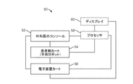
図1Bは、(図1AのMIRSシステム10のような)ロボット手術システム50を概略的に示す。上述のように、(図1Aの外科医側コンソール16のような)外科医側コンソール52は、(図1Aの患者側カート22のような)患者側カート(手術ロボット)54を制御するために、低侵襲手術中に外科医によって使用されることができる。患者側カート54は、手術部位の画像をキャプチャし且つキャプチャした画像を(図1Aの電子機器カート24のような)電子機器カート56に出力するために、立体内視鏡のような、撮像装置を使用することができる。上述のように、電子機器カート56は、任意の後続の表示の前に、キャプチャした画像を様々な方法で処理することができる。例えば、電子機器カート56は、外科医側コンソール52を介して合成画像を外科医に表示する前に、キャプチャした画像を仮想制御インターフェイスに重ねる(オーバーレイする)ことができる。患者側カート54は、電子機器カート56の外部で処理するためにキャプチャした画像を出力することができる。例えば、患者側カート54は、キャプチャした画像をプロセッサ58に出力することができ、このプロセッサはキャプチャした画像を処理するために使用されることができる。画像はまた、電子機器カート56及びプロセッサ58の組み合わせによっても処理されることができ、この電子機器カート56及びプロセッサ58は、キャプチャした画像を一緒に、順番に、及び/又はこれらの組み合わせで処理するように、共に結合されることができる。1又は複数の別個のディスプレイ60もまた、手術部位の画像のような画像の、又は他の関連画像の局所的及び/又は遠隔表示のために、プロセッサ58及び/又は電子機器カート56に結合されることができる。
FIG. 1B schematically illustrates a robotic surgery system 50 (such as the
図2は、外科医側コンソール16の斜視図である。外科医側コンソール16は、奥行き知覚を可能にする手術部位の調整された立体視を外科医18に表示するための左眼用ディスプレイ32と右眼用ディスプレイ34とを含む。コンソール16はさらに、1又は複数の入力制御装置36を含み、この入力制御装置は、(図1Aに示される)患者側カート22に1又は複数のツールを操作させる。入力制御装置36は、外科医にテレプレゼンスを、又は外科医がツール26を直接的に制御するための強く認識できる感覚を有するように、入力制御装置36がツール26と一体であるという知覚を提供するように、(図1Aに示される)それらに関連付けられるツール26と同じ自由度を提供することができる。この目的を達成するために、位置、力、及び触覚フィードバックセンサ(図示せず)が、位置、力、及び触覚感覚を、ツール26から入力制御装置36を介して外科医の手に戻って送信するために用いられ得る。
FIG. 2 is a perspective view of the
外科医側コンソール16は、通常、外科医が手術を直接的に監視し得るように、必要に応じて物理的に存在するように、そして電話又は他の通信媒体を介して話すのではなく、助手に直接的に話すように、患者と同じ部屋に位置している。しかし、外科医は、別の部屋、完全に異なる建物、又は遠隔外科手術を許可している患者から遠隔の他の場所に位置することができる。
The surgeon's
図3は、電子機器カート24の斜視図である。電子機器カート24は、内視鏡28と結合されることができ、外科医側コンソール上で外科医に、又は局所的に及び/又は遠隔に位置する別の適切なディスプレイ上でのような、後続の表示のためにキャプチャした画像を処理するためのプロセッサを含むことができる。例えば、立体内視鏡が使用される場合、電子機器カート24は、手術部位の調整された立体画像を外科医に提示するように、キャプチャした画像を処理することができる。このような調整は、対向する画像同士間の位置合わせを含むことができ、且つ立体内視鏡の立体作動距離を調節することを含むことができる。別の例として、画像処理は、光学収差のような、画像取込装置の結像誤差を補償するように、以前に決定されたカメラ較正パラメータの使用を含むことができる。
FIG. 3 is a perspective view of the
図4は、複数のマニピュレータアームを有する患者側カート22を示し、各アームは、手術器具又はツール26をマニピュレータアームの遠位端部で支持する。示される患者側カート22は、手術ツール26、又は手術部位の画像をキャプチャするために使用される立体内視鏡のような撮像装置28のいずれかを支持するために使用されることができる、4つのマニピュレータアーム100を含む。操作は、多数のロボット関節を有するロボットマニピュレータアーム100によって提供される。撮像装置28及び手術ツール26は、運動学的遠隔中心が切開部の大きさを最小にするよう切開部に維持されるように、患者の切開部を介して位置決めされ且つ操作されることができる。手術部位の画像は、手術器具又はツール26が撮像装置28の視野内に配置されるとき、手術器具又はツール26の遠位端部の画像を含むことができる。
FIG. 4 shows a
手術ツール26に関して、種々の代替のロボット手術ツール又は異なる種類の器具及び様々なエンドエフェクタが、使用されることができ、マニピュレータの少なくともいくつかの器具は、外科手術中に取り外されるとともに置き換えられる。DeBakey鉗子、マイクロピンセット、ポッツはさみ、及びクリップアプライヤを含む、これらのエンドエフェクタのいくつかは、エンドエフェクタ顎部のペアを規定するように、互いに対して枢動する第1及び第2のエンドエフェクタ要素を含む。メス及び電気焼灼プローブを含む他のエンドエフェクタは、単一のエンドエフェクタ要素を有する。エンドエフェクタ顎部を有する器具に関して、顎部は大抵、ハンドルの把持部材を絞ることによって作動される。単一のエンドエフェクタ器具もまた、例えば電気焼灼プローブにエネルギを与えるために、把持部材の把持によって作動され得る。
With respect to the
器具26の細長いシャフトは、エンドエフェクタ及びシャフトの遠位端部が、低侵襲開口部を通して、大抵、腹壁等を通して手術作業部位に遠位に挿入されることを可能にする。手術作業部位はガス注入されることができ、患者内のエンドエフェクタの運動は、大抵、シャフトが低侵襲開口部を通過する位置の周りに器具26を枢動させることによって、少なくとも部分的に生み出される。換言すれば、マニピュレータ100は、エンドエフェクタの所望の動きを提供するのに役立つように、シャフトが低侵襲開口部位置を通って延びるように、器具の近位ハウジングを患者の外部で動かす。こうして、マニピュレータ100は、大抵、外科手術中、患者Pの外側で大きな動きを受ける。
The elongated shaft of the
本発明の多くの実施形態による例示的なマニピュレータアームは、図5A−12Cを参照して理解することができる。上述のように、マニピュレータアームは、一般的に、遠位器具又は手術ツールを支持し、ベースに対する器具の動きをもたらす。異なるエンドエフェクタを有する多数の異なる器具が、(典型的には、外科助手の助けを借りて)外科手術中に、各マニピュレータに順番に取り付けられるので、遠位器具ホルダは、好ましくは、取り付けられた器具又はツールの迅速な取り外し及び交換を可能にする。図4を参照して理解することができるように、マニピュレータは、患者側カートのベースに対して近位に取り付けられる。典型的には、マニピュレータアームは、ベースと遠位器具ホルダとの間に延びる複数のリンク機構及び関連する関節を含む。一態様では、例示的なマニピュレータは、マニピュレータアームの関節が与えられたエンドエフェクタ位置に対して異なる形態の範囲に駆動されることができるように、冗長自由度を有する複数の関節を含む。これは、本明細書に開示されたマニピュレータアームの実施形態のいずれの場合でも適用され得る。 An exemplary manipulator arm according to many embodiments of the present invention can be understood with reference to FIGS. 5A-12C. As mentioned above, the manipulator arm generally supports the distal instrument or surgical tool, resulting in movement of the instrument relative to the base. The distal instrument holder is preferably attached, as a number of different instruments with different end effectors are attached to each manipulator in turn during surgery (typically with the aid of a surgical assistant) Allow for rapid removal and replacement of tools or tools. As can be understood with reference to FIG. 4, the manipulator is mounted proximal to the base of the patient side cart. Typically, the manipulator arm includes a plurality of linkages and associated joints extending between the base and the distal instrument holder. In one aspect, the exemplary manipulator includes a plurality of joints with redundant degrees of freedom, such that the articulated arms of the manipulator arm can be driven to a range of different configurations for a given end effector position. This may apply to any of the embodiments of the manipulator arm disclosed herein.
図5Aに示されるような、多くの実施形態では、マニピュレータアームは、マニピュレータアームを関節の遠位で関節軸回りに回転させるように、第1関節軸の回りに回転する近位回転関節J1を含む。回転関節J1は、ベースに直接取り付けられ得る、或いは1又は複数の可動リンク機構又は関節に取り付けられ得る。マニピュレータの関節は、組み合わされて、マニピュレータアームの関節が、与えられたエンドエフェクタ位置について異なる形態の範囲内で駆動されることができるように、冗長自由度を有する。例えば、図5A−5Dのマニピュレータアームは、異なる形態で操作され得る一方、器具ホルダ510内に支持された(ツール512又は器具シャフトが貫通するカニューレのような)遠位部材511は、特定の状態を維持し且つエンドエフェクタの与えられた位置又は速度を含み得る。遠位部材511は、典型的には、ツールシャフト512が通って延びるカニューレであり、器具ホルダ501は、典型的には、カニューレを通って患者の体内に低侵襲開口部を通って延びる前に器具が付く(スパー上を並進する煉瓦状構造として示される)キャリッジである。
In many embodiments, as shown in FIG. 5A, the manipulator arm rotates the proximal revolute joint J1 which rotates about the first joint axis to rotate the manipulator arm about the joint axis distal to the joint. Including. The revolute joint J1 may be attached directly to the base or may be attached to one or more moveable linkages or joints. The joints of the manipulator combine to have redundant degrees of freedom so that the joints of the manipulator arm can be driven within different configurations for a given end effector position. For example, while the manipulator arm of FIGS. 5A-5D may be manipulated in different forms, the distal member 511 (such as the
図5A−図5Dのマニピュレータアーム500の個々のリンクを、図5A−図5Dに示されるようにリンクを接続する関節の回転軸に沿って説明すると、第1のリンク504は、その関節軸の回りを枢動する枢動関節J2から遠位に延び、その関節軸の回りを回転する回転関節J1に結合される。図5Aに示されるように、関節の残りの多くは、それらの関連付けられる回転軸によって識別されることができる。例えば、示されるように、第1のリンク504の遠位端部は、その枢動軸の回りを枢動する枢動関節J3で第2のリンク506の近位端部に結合され、第3のリンク508の近位端部は、その軸線の回りを枢動する枢動関節J4で第2のリンク506の遠位端部に結合される。第3のリンク508の遠位端部は、枢動関節J5で器具ホルダ510に結合される。典型的には、関節J2、J3、J4、及びJ5のそれぞれの枢動軸は、実質的に平行であり、且つ図5Dに示されるように、互いに隣接して位置決めされたときに、リンク機構は、マニピュレータアームの減少幅wを提供するとともにマニピュレータアセンブリの操縦中の患者クリアランスを向上させるように、「積み重ねられた(stacked)」ように見える。幾つかの実施形態では、器具ホルダは、低侵襲開口部を通る器具306の軸方向運動を容易にするとともに、器具が摺動自在に挿通されるカニューレに対して器具ホルダの取り付けを容易にする直動関節J6のような、追加の関節を含む。
To illustrate the individual links of the
この例示的なマニピュレータアームでは、遠位部材又はそこを通ってツール512が延びるカニューレ511は、器具ホルダ510の遠位に追加の自由度を含み得る。器具の自由度の作動は、大抵、マニピュレータのモータで駆動され、代替実施形態は、クイック取り外し可能器具ホルダ/器具インターフェイスにおいて、器具を、支持マニピュレータ構造から分離することができ、それによって、器具上に存在するものとしてここで示される1又は複数の関節が、代わりに、インターフェイス上に存在し、またその逆になる。いくつかの実施形態では、カニューレ511は、ツール先端の挿入ポイント又は枢動ポイントPPの近く又は近位の回転関節J8(図示せず)を含み、このツール先端の挿入ポイント又は枢動ポイントは、一般的に低侵襲開口部の部位に配置される。器具の遠位手首は、器具手首における1又は複数の関節の器具関節軸周りの手術ツール512のエンドエフェクタの枢動運動を可能にする。エンドエフェクタ顎部要素の間の角度は、エンドエフェクタの位置及び配向とは独立して制御され得る。
In this exemplary manipulator arm, the distal member or
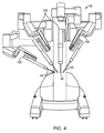
例示的なマニピュレータアセンブリの動作範囲は、図6A−6Cを参照することによって理解することができる。手術中、例示的なマニピュレータアームは、手術作業部位内の特定の患者組織にアクセスすることが必要なとき、図6Aに示されるように、ピッチフォワード形態に、又は図6Bに示されるように、ピッチバック形態に操作されることができる。典型的なマニピュレータアセンブリは、少なくとも±60度で、好ましくは約±75度で前方及び後方にピッチ動作することができ、且つまた±80度でヨー動作することができるエンドエフェクタを含む。この態様は、アセンブリでエンドエフェクタの増大した操作性を可能にするが、特に、マニピュレータアームが図6A及び6Bに示されるように、最大のピッチフォワード又は最大のピッチバック形態にあるとき、エンドエフェクタの運動が制限され得る形態があり得る。この実施形態では、マニピュレータアームは、外側ピッチに関して(±75度)の、及び外側ヨー関節に関して(±300度)の動作範囲(ROM)をそれぞれ有する。幾つかの実施形態では、ROMは、(±90度)より大きいROMを提供するように外側ピッチに関して増大されることができ、この場合、「沈黙円錐(cone of silence)」は完全に消されることができるが、一般的に挿入制限に関連付けられる内球はそのままである。マニピュレータは増大又は減少したROMを有するように構成され得ることができ、上述のROMは説明目的で提供され、さらに、本発明は本明細書に記載されるROMに限定されるものではないことが理解される。 The range of motion of an exemplary manipulator assembly can be understood by reference to FIGS. 6A-6C. During surgery, the exemplary manipulator arm needs to access specific patient tissue within the surgical work site, as shown in FIG. 6A, in a pitch forward configuration, or as shown in FIG. 6B. It can be operated in a pitch back configuration. A typical manipulator assembly includes an end effector capable of pitching forward and backward at least ± 60 °, preferably about ± 75 °, and also capable of yawing at ± 80 °. This aspect allows for increased maneuverability of the end effector in the assembly, but in particular when the manipulator arm is in maximum pitch forward or maximum pitch back configuration as shown in FIGS. 6A and 6B, the end effector There may be some forms in which the exercise of the subject may be restricted. In this embodiment, the manipulator arms have an operating range (ROM) of (± 75 degrees) with respect to the outer pitch and (± 300 degrees) with respect to the outer yaw joint, respectively. In some embodiments, the ROM can be increased with respect to the outer pitch to provide a ROM greater than (± 90 degrees), in which case the “cone of silence” is completely erased But the inner sphere generally associated with the insertion restriction remains. The manipulator may be configured to have an increased or decreased ROM, the above-mentioned ROM is provided for the purpose of illustration, and furthermore, the invention is not limited to the ROM described herein. Be understood.
図6Cは、図5A−5Bの例示的なマニピュレータのツール先端の全動作範囲及び作業空間を図式的に示す。作業空間は半球として示されているが、関節J1のような、マニピュレータの1又は複数の回転関節の動作範囲及び構成に依存して球としても示され得る。示されるように、図6Cの半球は、中心の、球状の空隙並びに2つの円錐状の空隙を含む。空隙は、ツール先端の運動が、機械的な拘束条件のために不可能又は、エンドエフェクタの運動を難しく若しくは遅くする過度に高い関節速度のために実行不可能であり得る領域を示す。これらの理由のために、円錐状の空隙は、「沈黙円錐(cone of silence)」と称される。幾つかの実施形態では、マニピュレータアームは、円錐内のあるポイントで特異点に到達し得る。沈黙円錐内又は沈黙円錐近くでのマニピュレータの運動は損なわれ得るので、マニピュレータのリンク機構及び関節を再配置するためにマニピュレータの1又は複数のリンクを手動で動かすことなしに、マニピュレータアームを沈黙円錐から離すことは難しく、この手動で動かすことは大抵、代替動作モードを必要とし且つ手術を遅らせる。 FIG. 6C schematically illustrates the full working range and working space of the tool tip of the exemplary manipulator of FIGS. 5A-5B. Although the work space is shown as a hemisphere, it may also be shown as a sphere depending on the operating range and configuration of one or more revolute joints of the manipulator, such as joint J1. As shown, the hemisphere of FIG. 6C includes a central, spherical void as well as two conical voids. The air gaps indicate areas where tool tip motion may not be possible due to mechanical constraints or impracticably high joint speeds which make end effector movement difficult or slow. For these reasons, conical air gaps are referred to as "cone of silence". In some embodiments, the manipulator arm may reach a singularity at a point in the cone. Because motion of the manipulator within or near the silence cone can be impaired, the manipulator cone can be silence cone without manually moving one or more links of the manipulator to reposition the manipulator linkages and joints. It is difficult to move away and this manual movement usually requires an alternative operating mode and delays the surgery.
これらの円錐部分への又はこれらの円錐部分の近くの器具シャフトの運動は、典型的には、マニピュレータの遠位リンク機構の間の角度が比較的小さいときに、発生する。このような形態は、(リンク機構が互いに対してより直交位置に動かされるように)リンク機構の間の角度を増加させるためにマニピュレータを再配置することによって回避されることができる。例えば、図6A及び6Bに示された形態では、最遠位リンクと器具ホルダとの間の角度(角度a)が比較的小さくなるとき、マニピュレータの運動はより困難になる。様々な実施形態の残りの関節における関節運動の範囲に依存して、あるリンク機構の間の角度が減少するとき、マニピュレータの運動は、妨げられる場合があり、幾つかの場合には、マニピュレータアームはもはや冗長ではなくなり得る。器具シャフトがこれらの円錐状部分に近づく、又はリンク機構間の角度が比較的低いマニピュレータ形態は、マニピュレータアームの操作性及び器用さが制限されるように「不完全な状態」にあると言われる。器用さ及び運動の範囲を維持するようにマニピュレータが「良い状態」にあることが望ましい。1つの態様では、本発明は、ユーザが、手術におけるエンドエフェクタの運動中でさえ、要望通りにマニピュレータを再配置するための指令を単に入力することによって、上述の円錐部分近くの器具シャフトの運動を避けることを可能にする。この態様は、マニピュレータが、何らかの理由で、「不完全な状態」になる場合に、特に有益である。 Movement of the instrument shaft to or near these conical portions typically occurs when the angle between the distal linkages of the manipulators is relatively small. Such a configuration can be avoided by repositioning the manipulators to increase the angle between the linkages (so that the linkages are moved to a more orthogonal position relative to one another). For example, in the configuration shown in FIGS. 6A and 6B, the motion of the manipulator becomes more difficult when the angle (angle a) between the most distal link and the instrument holder is relatively small. Depending on the range of articulation in the remaining joints of the various embodiments, the motion of the manipulator may be impeded when the angle between certain linkages decreases, and in some cases the manipulator arm May no longer be redundant. Manipulator configurations in which the instrument shaft approaches these conical parts, or where the angle between linkages is relatively low, are said to be "incomplete" such that the maneuverability and dexterity of the manipulator arm is limited . It is desirable for the manipulator to be "in good condition" to maintain the dexterity and range of motion. In one aspect, the present invention provides for movement of the instrument shaft near the conical portion described above simply by the user entering commands to reposition the manipulator as desired, even during movement of the end effector in surgery. Make it possible to avoid. This aspect is particularly useful when the manipulator is in an "incomplete state" for any reason.
上述のマニピュレータの実施形態は本発明に利用され得るが、幾つかの実施形態は、追加の関節を含むことができ、この追加の関節はまた、マニピュレータアームの器用さ及び調整を改良するために使用され得る。例えば、例示的なマニピュレータは、図5Aのマニピュレータアーム、及び、沈黙円錐を減少又は排除するために回転関節の軸周りの、それに関連付けられる、沈黙円錐を回転させるために使用されることができる、関節J1の近位の回転関節及び/又はリンク機構、を含み得る。他の実施形態では、例示的なマニピュレータはまた、器具ホルダを関節J5と実質的に直交する軸周りに枢動させる遠位枢動関節を含むことができ、それによって、沈黙円錐をさらに減少させ且つ手術ツールの運動範囲を向上させるようにツール先端をオフセットする。さらに他の実施形態では、J1のような、マニピュレータアームの近位関節が、必要に応じて沈黙円錐を動かす又は位置を変える且つマニピュレータツール先端の動作範囲を向上させるように、ベースに移動可能に取り付けられ得る。このような追加の関節の使用及び利点は、図7A−12Cを参照することによって理解されることができ、これらの図はこのような関節の例を示し、このような関節は、それぞれ、本明細書に記載される例示的なマニピュレータアームのいずれかの中で、互いに独立して使用され得る又は組み合わせて使用され得る。 Although the embodiments of the manipulator described above may be utilized in the present invention, some embodiments may include additional joints, which also improve the dexterity and adjustment of the manipulator arm. It can be used. For example, an exemplary manipulator can be used to rotate the manipulator arm of FIG. 5A and its associated silent cone about the axis of the revolute joint to reduce or eliminate the silent cone. It may include a rotational joint and / or a link mechanism proximal to the joint J1. In other embodiments, the exemplary manipulator can also include a distal pivot joint that pivots the instrument holder about an axis substantially orthogonal to joint J5, thereby further reducing the silence cone. And offset the tool tip to improve the range of motion of the surgical tool. In yet another embodiment, the proximal joint of the manipulator arm, such as J1, is moveable to the base to move or reposition the silent cone as needed and to improve the working range of the manipulator tool tip It can be attached. The use and benefits of such additional joints can be understood by reference to FIGS. 7A-12C, which show examples of such joints, each such joint being In any of the exemplary manipulator arms described herein, they may be used independently or in combination with one another.
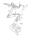
図7A−7Bは、例示的なマニピュレータアームでの使用のための追加の冗長関節−マニピュレータアームの近位部分をベースに結合する第1の関節を示す。第1の関節は、マニピュレータアームを関節J1’の関節軸周りに回転させる近位回転関節J1’である。近位回転関節J1’は、関節J1を近位回転関節J1’から所定の距離又は角度だけオフセットするリンク501を含む。リンク501は、図7Aに示されるように、湾曲リンク機構、又は図7Bに示されるように、直線又は傾斜リンク機構であることができる。典型的には、関節J1’の関節軸は、図7Aのそれぞれに示されるように、遠隔中心RC又はツール先端の挿入ポイントと位置合わせされる。例示的な実施形態では、関節J1’の関節軸は、体壁での動作を防ぐために、マニピュレータアームのそれぞれの他の回転関節がするように、遠隔中心を通過し、したがって、手術中に動かされることができる。関節J1’の軸は、アームの近位部分に結合されるので、アームの後部の位置及び配向を変更するために使用されることができる。一般的に、これのような、冗長軸は、器具先端が、外科医の指令に従うことを可能にする一方同時に他のアーム又は患者の解剖学的構造との衝突を回避する。1つの態様では、近位回転関節J1’は、単にフロアに対するマニピュレータの取付角度を変更するために使用される。この角度は、1)外部の患者の解剖学的構造との衝突を回避し且つ2)体内の解剖学的構造に到達するために、重要である。典型的には、近位回転関節J1’に取付けられたマニピュレータの近位リンクと近位回転の軸との間の角度aは約15度である。
7A-7B illustrate a first joint coupling the proximal portion of an additional redundant joint-manipulator arm to a base for use with an exemplary manipulator arm. The first joint is a proximal revolute joint J1 'that rotates the manipulator arm around the joint axis of the joint J1'. The proximal rotational joint J1 'includes a
図7Bは、近位回転関節J1’とその関連付けられる関節軸と例示的なマニピュレータアームの沈黙円錐との関係を示す。近位回転関節J1’の関節軸は、沈黙円錐を通過し得る又は沈黙円錐の完全に外側にあり得る。近位回転関節J1’の軸周りにマニピュレータアームを回転させることによって、沈黙円錐は(関節J1’軸が沈黙円錐を通過する実施形態において)減らされることができる、又は(近位回転関節軸が沈黙円錐の完全に外側に延びる実施形態において)有効に除去されることができる。リンク501の距離及び角度は、沈黙円錐に対する関節J1’軸の位置を決定する。
FIG. 7B shows the relationship between the proximal revolute joint J1 'and its associated joint axis and the silence cone of the exemplary manipulator arm. The joint axis of the proximal revolute joint J1 'may pass through the silence cone or be completely outside the silence cone. By rotating the manipulator arm about the axis of the proximal revolute joint J1 ', the silence cone can be reduced (in embodiments where the joint J1' axis passes through the silence cone) or It can be effectively eliminated in embodiments extending completely outward of the silent cone. The distance and angle of the
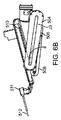
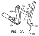
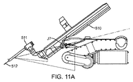
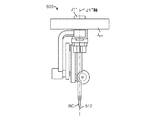
図8−9は、例示的なマニピュレータアームでの使用のための他の種類の冗長関節を示し、遠位回転関節J7は、器具ホルダ510をマニピュレータアーム508の遠位リンクに結合する。遠位回転関節J7は、システムが、関節軸周りに器具ホルダ510を横方向に枢動させる又はねじることを可能にし、この関節軸は、典型的には、遠隔中心又は挿入点を通過する。理想的には、回転関節はアームの遠位に位置し、したがって、特に、挿入軸の配向を動かすことによく適合している。この冗長軸の追加は、マニピュレータが、任意の1つの器具先端位置に対して多数の位置を取ることを可能にする。一般的に、これのような冗長軸は、他のアーム又は患者の解剖学的構造との衝突を回避しながら、器具先端が、外科医の指令に従うことを可能にする。遠位回転関節J7は挿入軸をヨー軸の近くに動かす能力を有するので、マニピュレータアームがピッチバック位置にあるとき動作範囲を増加させることができる。図10A−10Cは、関節J7の連続的な運動及びどのように関節J7の運動がツール先端の挿入軸を左右に移動させるかを示す。
8-9 show another type of redundant joint for use with the exemplary manipulator arm, where the distal revolute joint J7 couples the
他の態様では、本明細書に記載されたシステムのいずれも、1又は複数の関節を駆動するように且つマニピュレータアームの1又は複数の関節を様々な理由のために所望の再配置を生じさせるようゼロ空間内に再配置するように、ユーザ入力装置を利用し得る。上述のように指令再配置のためのユーザ入力部又はクラッチモードの一方又は両方を有する実施形態では、システムは、指令操作運動を生じさせるために運動中に上述の拘束条件を利用し得るとともに、再配置運動中又はクラッチモードの間、拘束条件の適用を中断し得る。再配置運動が完了する又はマニピュレータアームがクラッチモードから切り替えられるとき、システムは、マニピュレータアームの再配置された位置にしたがって、位置ベースの拘束条件を適用する。他の実施形態では、拘束条件は、デカルト座標空間内の最も近い経路に関連付けられる拘束条件が選択されることができるように、運動の複数の位置経路を定め得る。これらの態様は、システムが、駆動された再配置又はクラッチモードの間の手動再配置による、再配置された後のマニピュレータアームの1又は複数の関節の所望の運動を提供することを可能にする。 In other aspects, any of the systems described herein cause desired repositioning to drive one or more joints and for one or more joints of the manipulator arm for various reasons. A user input device may be utilized to relocate into zero space. In embodiments having one or both of the user input or the clutch mode for command relocation as described above, the system may utilize the constraints described above during exercise to produce the commanded motion; The application of restraint conditions may be interrupted during the repositioning motion or during the clutch mode. When the repositioning motion is complete or the manipulator arm is switched out of the clutch mode, the system applies a position based constraint according to the repositioned position of the manipulator arm. In other embodiments, the constraints may define multiple position paths of motion such that the constraint associated with the closest path in Cartesian coordinate space can be selected. These aspects allow the system to provide the desired motion of one or more joints of the manipulator arm after being repositioned by manual repositioning during driven repositioning or clutch mode .
遠位回転関節J7のような、追加の冗長関節を使用する1つの利点は、それが患者クリアランス円錐を減少させ得ることであり、この患者クリアランス円錐は、患者と器具ホルダ又はマニピュレータアームの遠位リンク機構との間の衝突を回避するように患者を除去しなければならない切開ポイントの近位のマニピュレータアームの遠位部分の掃引容積(swept volume)である。図11Aは、遠位回転関節の角度変位が0°のままである間のマニピュレータアームの近位部分の患者クリアランス円錐を示す。図11Bは、遠位回転関節がその軸周りに90°の角度変位を有して示される間のマニピュレータアームの近位部分の減少した患者クリアランス円錐を示す。したがって、挿入ポイントの近くに最少の患者クリアランスを有する手術では、本発明による関節J7の使用は、遠隔中心位置又は要望通りのエンドエフェクタ位置を維持しながら追加のクリアランスを提供し得る。 One advantage of using an additional redundant joint, such as the distal revolute joint J7, is that it can reduce the patient clearance cone, which is distal to the patient and the instrument holder or manipulator arm The swept volume of the distal portion of the manipulator arm proximal to the dissection point where the patient must be removed to avoid collisions with the linkage. FIG. 11A shows the patient clearance cone of the proximal portion of the manipulator arm while the angular displacement of the distal revolute joint remains at 0 °. FIG. 11B shows the reduced patient clearance cone of the proximal portion of the manipulator arm while the distal revolute joint is shown having an angular displacement of 90 ° about its axis. Thus, in surgery with minimal patient clearance near the insertion point, use of the joint J7 according to the present invention may provide additional clearance while maintaining the remote center position or end effector position as desired.
図12A−12Cは、例示的なマニピュレータアームと共に使用するための他の種類の冗長関節を示し、近位関節は、軸周りにマニピュレータアームを並進又は回転させる。多くの実施形態では、この近位並進移動可能関節は、マニピュレータアームのより良い調整及び改良された操作性を提供するためにマニピュレータアームの動作範囲を変える又は回転させることによって沈黙円錐を減少又は排除するように、関節J1又はJ1’のような、マニピュレータの近位関節を経路に沿って並進移動させる。並進移動可能関節は、図12A−12Dに関節J1”で示されるように、円形経路を含み得る、又は、図13A−13Cに示されるように、半円形又はアーチ形経路を含み得る。一般的に、関節は、その周りをカニューレ511を通って延びるツール512のシャフトが枢動する遠隔中心RCと交差する並進移動可能関節の軸周りにマニピュレータアームを回転させる。図12A−12Cに示された実施形態では、J1”の軸は垂直軸であるが、J1”の軸は水平又は様々な傾斜角度であり得ることが理解される。
12A-12C illustrate another type of redundant joint for use with the exemplary manipulator arm, where the proximal joint translates or rotates the manipulator arm about an axis. In many embodiments, this proximal translatable joint reduces or eliminates silence cones by changing or rotating the operating range of the manipulator arm to provide better adjustment and improved maneuverability of the manipulator arm. To translate the proximal joint of the manipulator, such as joint J1 or J1 ′, along the path. The translatable joint may include a circular path, as shown by joints J1 ′ ′ in FIGS. 12A-12D, or may comprise a semicircular or arched path, as shown in FIGS. 13A-13C. The joint rotates the manipulator arm about the axis of the translatable joint intersecting the remote center RC about which the shaft of the
幾つかの実施形態では、マニピュレータアーム500は、近位又は遠位回転関節、近位並進移動可能関節及び遠位リンク機構の平行四辺形構造のいずれか又は全てを含み得る。これらの特徴のいずれか又は全ての使用は、追加の冗長自由度を提供し、リンク機構の間の角度を増加させ、それによってマニピュレータの器用さ及び動作を向上させることによって、より良く「調整された」マニピュレータアセンブリを提供するように、本発明による再配置を容易にする。この例示的なマニピュレータの増加した柔軟性はまた、関節限度、特異点等を回避するために、マニピュレータリンク機構の運動学を最適化するために使用されることができる。
In some embodiments,
幾つかの態様では、マニピュレータの関節運動は、システムのモータを使用してコントローラにより1又は複数の関節を駆動することによって制御され、関節は、コントローラのプロセッサによって計算された、調整された関節運動に従って駆動される。数学的には、コントローラは、ベクトル及び/又は行列を使用して関節指令の計算の少なくとも幾つかを実行することができ、そのうちのいくつかは、関節の形態又は速度に対応する要素を有し得る。プロセッサに利用可能な代替の関節形態の範囲は、関節空間として概念化され得る。関節空間は、例えば、マニピュレータが自由度を有するのと同数の次元を有し得るとともに、マニピュレータの特定の形態は、関節空間内の特定の点を表すことができ、各座標は、マニピュレータの関連付けられる関節の関節状態に対応する。 In some aspects, the articulation of the manipulator is controlled by driving one or more joints by the controller using a motor of the system, the joints being adjusted articulations calculated by the processor of the controller It is driven according to Mathematically, the controller can perform at least some of the calculations of joint commands using vectors and / or matrices, some of which have elements corresponding to the morphology or velocity of the joints obtain. The range of alternative joint forms available to the processor can be conceptualized as joint space. The joint space may have, for example, the same number of dimensions as the manipulator has degrees of freedom, and the particular form of the manipulator may represent a particular point in the joint space, each coordinate being associated with the manipulator Correspond to the joint condition of the joint being
1つの態様では、システムは、そのデカルト空間として本明細書で示される、作業空間における特徴部の指令位置及び速度が入力であるコントローラを含む。特徴部は、制御入力を使用して関節運動されることになる制御フレームとして使用できるマニピュレータ上の、又はマニピュレータから離れた任意の特徴部であり得る。本明細書に記載される多くの例で使用されるマニピュレータ上の特徴部の例は、ツール先端である。マニピュレータ上の特徴部の他の例は、ツール先端上に存在しないが、ピン又はペイントパターンのようなマニピュレータの一部である物理的な特徴部である。マニピュレータから離れた特徴部の例は、ツール先端から離れる正確な一定の距離及び角度である空き空間の基準点である。マニピュレータから離れた特徴部の他の例は、マニピュレータに対する位置が確立されることができる標的組織である。これら全ての場合において、エンドエフェクタは、制御入力を使用して関節運動されることになる仮想制御フレームに関連付けられる。しかし、以下では、「エンドエフェクタ」と「ツール先端」とは、同義的に使用される。一般的には、所望のデカルト空間のエンドエフェクタ位置を等価の関節空間位置にマッピングする閉じた形の関係はないが、一般的に、デカルト空間のエンドエフェクタと関節空間速度との間に閉じた形の関係がある。運動学的ヤコビアンは、関節空間位置要素に対するエンドエフェクタのデカルト空間位置要素の偏導関数の行列である。このように、運動学的ヤコビアンは、エンドエフェクタと関節との間の運動学的関係を捕える。換言すれば、運動学的ヤコビアンは、エンドエフェクタの関節動作の影響を捕える。運動学的ヤコビアン(J)は、以下の関係を用いて、関節空間速度(dq/dt)をデカルト空間エンドエフェクタ速度(dx/dt)にマッピングするために使用されることができる。 In one aspect, the system includes a controller whose input is the commanded position and velocity of the feature in the workspace, shown herein as its Cartesian space. The features may be any features on or away from the manipulator that can be used as a control frame to be articulated using control inputs. An example of a feature on a manipulator used in many of the examples described herein is a tool tip. Another example of a feature on the manipulator is a physical feature that is not present on the tool tip but is part of the manipulator, such as a pin or paint pattern. An example of a feature away from the manipulator is a reference point in free space which is the exact fixed distance and angle away from the tool tip. Another example of a feature remote from the manipulator is a target tissue whose position relative to the manipulator can be established. In all these cases, the end effector is associated with a virtual control frame to be articulated using the control input. However, in the following, "end effector" and "tool tip" are used interchangeably. Generally, there is no closed-form relationship that maps the desired Cartesian space end effector position to an equivalent joint space position, but generally a closed space between the Cartesian space end effector and the joint space velocity There is a form relationship. The kinematics Jacobian is a matrix of partial derivatives of Cartesian space location elements of the end effector relative to joint space location elements. Thus, the kinematic Jacobian captures the kinematic relationship between the end effector and the joint. In other words, the kinematic Jacobian captures the effects of end effector articulation. The kinematics Jacobian (J) can be used to map joint space velocity (dq / dt) to Cartesian space end effector velocity (dx / dt) using the following relationship:
dx/dt=J dq/dt
したがって、入力と出力位置との間に閉じた形のマッピングがない場合であっても、速度のマッピングが、指令ユーザ入力からマニピュレータの運動を実現するために、ヤコビアンベースのコントローラ等で、反復的に使用されることができる。しかし、様々な実装を使用することができる。多くの実施形態は、ヤコビアンベースのコントローラを含んでいるが、いくつかの実装は、本明細書で記載した特徴のいずれかを提供するために、マニピュレータアームのヤコビアンにアクセスするように構成され得る様々なコントローラを使用し得る。
dx / dt = J dq / dt
Thus, even if there is no closed form mapping between input and output positions, velocity mapping can be iteratively performed, such as with a Jacobian based controller, to achieve manipulator movement from commanded user input. Can be used. However, various implementations can be used. Many embodiments include a Jacobian-based controller, although some implementations may be configured to access the Jacobian of the manipulator arm to provide any of the features described herein. Various controllers may be used.
1つのそのような実装は、以下の簡略化された項で記述される。指令関節位置は、ヤコビアン(J)を計算するために使用される。各時間ステップ(Δt)の間、デカルト空間速度(dx/dt)が、所望の移動(dxdes/dt)を実行するとともに所望のデカルト空間位置からの蓄積された偏差(Δx)を補正するように、計算される。このデカルト空間速度は、次に、ヤコビアンの擬似逆行列(J#)を用いて、関節空間速度(dq/dt)に変換される。得られた関節空間指令速度は、次に、関節空間指令位置(q)を生成するために積分される。これらの関係は次の通りである。 One such implementation is described in the following simplified section. The commanded joint position is used to calculate the Jacobian (J). During each time step (Δt), the Cartesian space velocity (dx / dt) performs the desired movement (dx des / dt) and corrects the accumulated deviation (Δx) from the desired Cartesian space position To be calculated. This Cartesian space velocity is then converted to joint space velocity (dq / dt) using the Jacobian pseudoinverse (J # ). The obtained joint space commanded velocity is then integrated to generate a joint space commanded position (q). These relationships are as follows.
dx/dt=dxdes/dt+kΔx (1)
dq/dt=J#dx/dt (2)
qi=qi−1+dq/dtΔt (3)
ヤコビアン(J)の擬似逆行列は、所望のツール先端動作(いくつかの場合では、枢動ツール動作の遠隔中心)を関節速度空間に直接マッピングする。使用されているマニピュレータが、(6までの)ツール先端の自由度より多くの有用な関節軸を有している場合、マニピュレータは冗長であると言われる。例えば、ツール動作の遠隔中心が使用されるとき、マニピュレータは、遠隔中心の位置に関連付けられた3つの自由度について追加の3つの関節軸を有するべきである。冗長なマニピュレータのヤコビアンは、少なくとも1つの次元を有する「ゼロ空間」を含む。この文脈において、ヤコビアン(N(J))の「ゼロ空間」は、ツール先端動作を瞬時に実現しないような関節速度の空間である(そして、遠隔中心が使用されるとき、枢動点位置の移動がない)。そして「ゼロ動作」は、ツール先端及び/又は遠隔中心の位置の瞬間的な移動も生成しない関節位置の組み合わせ、軌道、又は経路である。マニピュレータの所望の再配置(本明細書に記載される任意の再配置を含む)を達成するために計算されたゼロ空間速度をマニピュレータの制御システムに組み込む又は注入することは、上記の式(2)を以下のように変形する:
dq/dt=dqprep/dt+dqnull/dt (4)
dqprep/dt=J#dx/dt (5)
dqnull/dt=(1−J#J)z=VnVn Tz=Vnα (6)
式(4)による関節速度は、2つの成分を有し:第1は、ゼロ直交空間成分、所望のツール先端動作を生成する「純粋な(purest)」関節速度(最短ベクトルの長さ)(そして、遠隔中心が使用されるときに、所望の遠隔中心動作)であり、第2の成分は、ゼロ空間成分である。式(2)及び式(5)は、ゼロ空間成分なしで、同じ式が得られることを示している。式(6)は、左辺のゼロ空間成分についての従来の形式で始まり、最も右寄りの右辺で、例示的なシステムで用いられる形式を示し、ここで、(Vn)は、ゼロ空間についての直交基底ベクトルのセットであり、(α)は、それら基底ベクトルをブレンドする(blending)ための係数である。いくつかの実施形態では、αは、要望通りにゼロ空間内の動作を形成又は制御するために、例えばノブ又は他の制御手段の使用によって等、制御パラメータ、変数又は設定によって決定される。
dx / dt = dx des / dt + kΔx (1)
dq / dt = J # dx / dt (2)
q i = q i-1 + dq / dtΔt (3)
The Jacobian (J) pseudoinverse directly maps the desired tool tip motion (in some cases the remote center of the pivoting tool motion) into the joint velocity space. A manipulator is said to be redundant if the manipulator being used has more useful joint axes than the degree of freedom of the tool tip (up to 6). For example, when the remote center of tool motion is used, the manipulator should have an additional three joint axes for the three degrees of freedom associated with the position of the remote center. The Jacobian of the redundant manipulators contains a "zero space" with at least one dimension. In this context, the Jacobian (N (J)) 's "zero space" is a space of joint velocities such that tool tip motion is not realized instantaneously (and, when remote centers are used, the pivot point position of No movement). And "zero motion" is a combination, trajectory, or path of joint positions that does not produce any instantaneous movement of the tool tip and / or remote center position. Incorporating or injecting the calculated zero space velocity into the control system of the manipulator to achieve the desired repositioning of the manipulator (including any repositioning described herein) can be achieved by Transform) as follows:
dq / dt = dq prep / dt + dq null / dt (4)
dq prep / dt = J # dx / dt (5)
dq null / dt = (1-J # J) z = V n V n T z = V n α (6)
The joint velocity according to equation (4) has two components: the first is a zero orthogonal space component, the "purest" joint velocity (shortest vector length) that produces the desired tool tip motion (the shortest vector length) And, when the remote center is used, the desired remote center operation), and the second component is the zero space component. Equations (2) and (5) show that the same equation is obtained without the zero space component. Equation (6) starts in the conventional form for the left-hand side null space component, and shows the form used in the example system on the far right-hand side, where (V n ) is orthogonal for the zero space A set of basis vectors, (α) are the coefficients for blending the basis vectors. In some embodiments, α is determined by control parameters, variables or settings, such as by use of knobs or other control means, to form or control movement in zero space as desired.
図13Aは、ヤコビアンのゼロ空間とヤコビアンのゼロ直交空間との間の関係を図式的に示す。図14は、水平軸に沿ったゼロ空間と、垂直軸に沿ったゼロ直交空間とを示す二次元の概略図を示し、これら2つの軸は、互いに直交する。斜めのベクトルは、ゼロ空間における速度ベクトルとゼロ直交空間における速度ベクトルの和を表し、この和は、上記の式(4)を表す。 FIG. 13A schematically illustrates the relationship between Jacobian zero space and Jacobian zero orthogonal space. FIG. 14 shows a two-dimensional schematic showing zero space along the horizontal axis and zero orthogonal space along the vertical axis, these two axes being orthogonal to one another. The diagonal vector represents the sum of the velocity vector in the zero space and the velocity vector in the zero orthogonal space, and this sum represents the equation (4) above.
図13Bは、「ゼロ動作多様体」として示される、4次元関節空間内のゼロ空間とゼロ動作多様体との間の関係を図式的に示す。各矢印(q1、q2、q3、及びq4)は、主要な関節軸を表す。閉曲線は、同じエンドエフェクタ位置を瞬時に実現する関節空間位置のセットであるゼロ動作多様体を表す。この曲線上の与えられた点Aに関して、ゼロ空間は、エンドエフェクタの運動を瞬時に生じさせない関節速度の空間であるので、ゼロ空間は、点Aでのゼロ動作多様体の接線に対して平行である。 FIG. 13B schematically illustrates the relationship between the zero space and the zero operating manifold in a four-dimensional joint space, shown as a “zero operating manifold”. Each arrow (q1, q2, q3, and q4) represents a major joint axis. The closed curve represents a zero motion manifold, which is a set of joint space positions that instantaneously realize the same end effector position. For a given point A on this curve, the zero space is parallel to the tangent of the zero motion manifold at point A, since the zero space is a space of joint velocities that does not cause the motion of the end effector instantaneously. It is.
図14は、例示的なマニピュレータアセンブリの関節空間の2次元部分空間を図式的に示す。水平及び垂直軸は、独立関節運動を有する2つの関節の運動、特に、マニピュレータアームの器具ホルダのピッチに影響を与える関節の運動(水平軸)対そこを通ってマニピュレータアームの近位部分が延びる面から器具ホルダを横にいずれのかの方向に枢動させる遠位回転関節の運動(垂直軸)を示す。部分空間の右端はピッチ関節の前方ピッチ限度を示し、左端はピッチ関節の後方ピッチ限度を示す。ピッチ関節の前方及び後方ピッチ限度近くの、曲線A、B及びC、D近くの、定められた経路は、それぞれ、マニピュレータアームの関節のヤコビアンのゼロ空間内の関節運動の関節状態を示す。例えば、与えられるエンドエフェクタ状態に対して、コントローラは、エンドエフェクタの所望の状態を維持しながら、曲線A、B、C及びDに直交する関節空間の範囲を増加させるように、曲線A、B、C及びDのそれぞれに沿って横方向枢動関節及びピッチ関節を動かすことができる。 FIG. 14 schematically illustrates a two-dimensional subspace of the joint space of an exemplary manipulator assembly. The horizontal and vertical axes extend the movement of two joints with independent articulation, in particular the movement of the joint (horizontal axis) which influences the pitch of the instrument holder of the manipulator arm, through which the proximal part of the manipulator arm extends Fig. 7 shows the movement (vertical axis) of the distal revolute joint pivoting the instrument holder laterally in any direction from a plane. The right end of the subspace indicates the forward pitch limit of the pitch joint and the left end indicates the backward pitch limit of the pitch joint. The defined paths near the anterior and posterior pitch limits of the pitch joint, and near the curves A, B and C, D, respectively indicate the joint state of articulation within the zero space of the Jacobian's joint of the manipulator arm. For example, for a given end effector state, the controller may increase the range of joint space orthogonal to the curves A, B, C and D while maintaining the desired state of the end effector, the curves A, B , C and D respectively, the lateral pivot joint and the pitch joint can be moved.
図14に示される曲線A、B、Cは、実質的に一定のデカルト空間ピッチを導く関節空間内の関節空間値を示す。各曲線は、図13Bに記載されるように、ゼロ動作多様体である。図14の関節空間によって示される特定のマニピュレータアームの動作中、より多くの経路曲線が、水平軸に近づくことによって前方ピッチを横切らされることができる(例えば、横方向枢動関節の角度変位がゼロ度に近づく)。代替的には、より多くの経路曲線が、関節空間の上隅方及び下隅に近づくことによって後方ピッチを横切らされることができる(例えば、横方向枢動関節の角度変位がその±極値に近づく)。 The curves A, B, C shown in FIG. 14 show joint space values in the joint space leading to a substantially constant Cartesian space pitch. Each curve is a zero operating manifold, as described in FIG. 13B. During operation of the particular manipulator arm illustrated by the joint space of FIG. 14, more path curves can be crossed the forward pitch by approaching the horizontal axis (e.g. the angular displacement of the lateral pivot joint is Approach zero degrees). Alternatively, more path curves can be crossed the posterior pitch by approaching the upper and lower corners of the joint space (eg, the angular displacement of the lateral pivot joint is at its ± extreme value) Approach).
図14に見ることができるように、示されたマニピュレータアームのデカルト座標関節空間は4つの隅を有する。一般的に、4つの隅にアクセスするためにマニピュレータアームの関節に対して、関節の運動を生じさせるコントローラは隅に向ける。1つの態様では、コントローラは、デカルト座標空間の遠くの隅へのマニピュレータアームのアクセスを改良するために、図14に示される関節空間内の曲線のような、関節空間の1又は複数の経路に沿って関節を動かすように、ヤコビアンのゼロ空間内の運動を計算する。1つのアプローチでは、ポテンシャル場が、曲線族に沿って関節を動かすためにマニピュレータアームの関節部分空間内に定められ、関節空間の端部及び隅に、又は様々な関節の組み合わせにおける関節限度及び特にデカルト座標空間の遠い到達範囲に到達することができるように使用される。関節空間内のピッチ関節及び横方向枢動関節範囲によって表されるデカルト空間到達範囲は、図14に示される。 As can be seen in FIG. 14, the Cartesian coordinate joint space of the manipulator arm shown has four corners. Generally, for the joints of the manipulator arm to access the four corners, the controller causing the movement of the joints points in the corners. In one aspect, the controller controls one or more paths of joint space, such as curves in joint space shown in FIG. 14, to improve manipulator arm access to the far corners of Cartesian coordinate space. Calculate Jacobian's motion in zero space as you move the joints along. In one approach, a potential field is defined in the joint subspace of the manipulator arm to move the joint along a family of curves, and the joint limits and in particular at the ends and corners of the joint space or combinations of various joints Used to be able to reach the far reach of Cartesian coordinate space. The Cartesian space coverage represented by the pitch and lateral pivot joints within the joint space is shown in FIG.
図14に示される、ポテンシャル場を定める1つの方法は、以下の通りである:
C=1/2(qpitch−qpitch−setpoint)2
Z=(dC/ct)T=∂C/∂q*dq/dt=(qpitch−qpitch−setpoint)*dq/dt
ここで、zは上述の式(6)でその後使用される。
One way to define the potential field, shown in FIG. 14, is as follows:
C = 1/2 (q pitch- q pitch-setpoint ) 2
Z = (dC / ct) T = ∂C / ∂q * dq / dt = (q pitch −q pitch−setpoint ) * dq / dt
Here, z is then used in equation (6) above.
代替的には、幾つかの態様では、ポテンシャル関数勾配を組み込み且つデカルト空間エンドエフェクタ速度に適用される拡張ヤコビアンが使用され得る。ヤコビアンの拡張は、要望通りに関節速度を計算する。ヤコビアンを使用して関節運動を計算することを述べることにおいて、このような計算は拡張ヤコビアンアプローチを含み得ることが理解される。拡張ヤコビアンアプローチにしたがって、以下の式が使用されるが、列ベクトルが使用され得ることが理解される:
dx/dt=J*dq/dt
y=h(q)
dy/dt=∂h/∂q*dq/dt
[dx/dtT dy/dtT]T=[JT ∂h/∂qT]T*dq/dt
d(x;y)/dt=[J;h’]*dq/dt
dq/dt=[J;h’]#d(x;y)/dt
1つの例では、y=h(q)をポテンシャル場関数の複素ネットワーク(complex network)に設定する。dy/dt=∂h/∂q*dq/dt。dy/dt及び∂h/∂q及びdq/dtは、ポテンシャル場関数に基づいて要望通りに決定されることができ、拡張された式は、エンドエフェクタを駆動すること及び関節空間で経路をたどることの両方の組み合わされた所望の結果を生成する。
Alternatively, in some aspects, an extended Jacobian that incorporates a potential function gradient and is applied to Cartesian space end effector velocity may be used. Jacobian dilation calculates joint velocity as desired. It is understood that in describing using the Jacobian to calculate joint motion, such calculations may include an expanded Jacobian approach. According to the extended Jacobian approach, it is understood that the following equations are used, but column vectors may be used:
dx / dt = J * dq / dt
y = h (q)
dy / dt = ∂h / ∂q * dq / dt
[Dx / dt T dy / dt T ] T = [J T ∂ h / ∂ q T ] T * dq / dt
d (x; y) / dt = [J; h '] * dq / dt
dq / dt = [J; h '] # d (x; y) / dt
In one example, y = h (q) is set to the complex network of potential field functions. dy / dt = ∂h / ∂q * dq / dt. dy / dt and ∂h / ∂q and dq / dt can be determined as desired based on the potential field function, and the expanded equations drive the end effector and follow the path in joint space Both produce the combined desired result.
コントローラは、所望のエンドエフェクタ操作運動を生じさせるように指令エンドエフェクタ変位運動にしたがってゼロ直交空間内で関節の運動を生じさせるために、ヤコビアンの疑似逆行列を使用して、経路A、B、C及びDに直角に関節を動かし得る。ピッチ関節のピッチが、指令エンドエフェクタ運動中に水平軸に沿って動くとき、システムは、関節空間の範囲を増加させるようにゼロ空間内で関節位置の運動を決定する。例えば、図14に示されるように、ピッチ関節の運動が後方限度に向かって動くとき、システムは、湾曲経路とマニピュレータ関節空間の限度との間の直交距離を増加させることによってゼロ直交空間内で関節動作の範囲を増加させるように、最も近い曲線(図14の曲線Bに沿った矢印参照)に沿ってゼロ空間内で横方向枢動関節の変位運動を決定するとともに同変位運動を生じさせ得る。例えば、図14に示される関節空間では、ピッチ関節が前方ピッチ関節限度に向かって動くとき、システムは、湾曲経路(C及びD)とピッチ関節前方限度との間の直交距離を増加させることによってゼロ直交空間内で動作範囲を増加させるように、非変位位置に向かって横方向枢動関節の運動を決定するとともに同運動を生じさせ得る。仮想ポテンシャル場空間が、関節空間内で関節の所望の運動を生じさせるために関節速度を決定するよう使用されることができる仮想力の決定を可能にするように、関節空間で使用され得る。 The controller uses the Jacobian pseudo-inverse to generate the motion of the joint in the zero orthogonal space according to the commanded end effector displacement motion to produce the desired end effector manipulation motion, path A, B, The joints can be moved at right angles to C and D. As the pitch of the pitch joint moves along the horizontal axis during commanded end effector movement, the system determines movement of the joint position in zero space to increase the extent of the joint space. For example, as shown in FIG. 14, when the motion of the pitch joint moves towards the posterior limit, the system can increase the orthogonal distance between the curved path and the limit of the manipulator joint space within the zero orthogonal space Determine the displacement movement of the lateral pivot joint in zero space along with the closest curve (see arrow along curve B in FIG. 14) to increase the range of joint movement, and make the same obtain. For example, in the joint space shown in FIG. 14, when the pitch joint moves towards the anterior pitch joint limit, the system increases the orthogonal distance between the curved path (C and D) and the pitch joint anterior limit The motion of the lateral pivot joint may be determined and produced towards the non-displaced position so as to increase the range of motion in the zero orthogonal space. Virtual potential field space may be used in the joint space to allow determination of virtual forces that can be used to determine joint velocity to produce the desired motion of the joint within the joint space.
幾つかの実施形態では、マニピュレータアームは、関節J3、J4、及びJ5が、相互に関係する運動で関節J3、J4、及びJ5並びに枢動点PP(例えば図5A参照)によって形成される平行四辺形を維持するように構成される、平行四辺形リンク機構を使用する。この相互に関係する運動のために、器具シャフトのピッチは、ピッチ関節(例えばJ3)の状態によって決定され得る。図5Aの関節J3のような、ピッチ関節の運動は、ピッチフォワード位置(図6A参照)からピッチバック位置(図6B参照)まで挿入軸のピッチを変化させる。様々な他の実施形態では、ピッチ関節は、マニピュレータアームの1又は複数の関節を含むことができ、これらの関節の運動は、器具シャフトのピッチを決定する。器具ホルダ510及び関連するカニューレ511を支持する遠位回転関節J7のような、遠位回転関節の運動は、そこを通って関節J7の近位のマニピュレータの部分が延びる平面に対して横方向に器具ホルダ510を通って延びる器具シャフトを枢動させる又はねじる。マニピュレータ関節空間の部分空間は、ピッチ関節J3、及び回転関節J7に関する関節状態の可能な組み合わせの範囲を示す。この実施形態では、位置の拘束条件は、上述のピッチ関節及び遠位回転関節によって定められる関節空間の部分空間内に定められるが、部分空間は、様々な他の関節によって又は3以上の関節によって定められ得ることが理解される。
In some embodiments, the manipulator arm is a parallelogram formed by joints J3, J4, and J5 and pivot point PP (see, eg, FIG. 5A) with joints J3, J4, and J5 in interrelated motions. Use parallelogram linkages, configured to maintain shape. Due to this interrelated motion, the pitch of the instrument shaft can be determined by the condition of the pitch joint (e.g. J3). Movement of the pitch joint, such as joint J3 of FIG. 5A, changes the pitch of the insertion axis from the pitch forward position (see FIG. 6A) to the pitch back position (see FIG. 6B). In various other embodiments, the pitch joint can include one or more joints of the manipulator arm, and the motion of these joints determines the pitch of the instrument shaft. The motion of the distal revolute joint, such as the distal revolute joint J7 supporting the
図示された実施形態では、湾曲経路に沿った運動は、増大したピッチバック位置へのピッチ関節の運動が回転関節の増大した回転変位に対応し、ピッチフォワード位置へのピッチ関節の運動が遠位回転関節の最小又はゼロ変位に対応するように、遠位回転関節及びピッチ関節の相対運動を含む。外側ピッチ関節がピッチバックされるとき、器具シャフトのツール先端は前方に動く。外側ピッチ関節が、ピッチバック位置の限度に達する場合、器具シャフト512の端部のツール先端の前方運動は、遠位回転関節J7の運動によって依然として達成されることができる。しかし、外側ピッチ関節J3がピッチバック位置の限度に近づくとき、遠位回転関節J7の運動を開始させることは、有益であり得る。同様に、後方の方向のツール先端運動を生じさせる、ピッチフォワード方向において、最も後方のツール先端位置は、遠位回転関節のゼロ角度変位である、遠位回転関節の運動が最小であるとき、得ることができる。
In the illustrated embodiment, movement along the curved path is such that movement of the pitch joint to the increased pitch back position corresponds to increased rotational displacement of the revolute joint and movement of the pitch joint to the pitch forward position is distal Includes relative motion of the distal revolute joint and the pitch joint to correspond to the minimum or zero displacement of the revolute joint. When the outer pitch joint is pitched back, the tool tip of the instrument shaft moves forward. When the outer pitch joint reaches the limit of the pitchback position, the forward movement of the tool tip at the end of the
1つの態様では、任意の時点で、経路又は曲線のいずれかの上にあることは、1次元ゼロ空間を要求する1次元拘束条件を満たすことと一致する。マニピュレータ関節空間のこの2次元部分空間は、定められた経路に向かって又は定められた経路に沿って、典型的には経路に沿って、対象関節状態の位置Xを「引っ張る」又は向ける傾向がある引力ポテンシャル場を作ることによって、マニピュレータアームの運動を所望の位置経路に向けるために使用されることができる。システムは、関節のアクセス容易化運動が、特定された関節を定められた経路セグメントに沿って動かすように構成され得る、又は、マニピュレータの関節の与えられた状態に対して関節の少なくとも1つの関節空間内で運動の増大された範囲を提供するように、定められた経路に沿って動かすためにポテンシャル場の中で様々な大きさの引力を使用し得る。 In one aspect, at any point in time, being on either a path or a curve is consistent with satisfying a one-dimensional constraint condition requiring a one-dimensional zero space. This two-dimensional subspace of the manipulator joint space tends to "pull" or direct the position X of the subject joint state towards or along the defined path, typically along the path. By creating an attractive potential field, it can be used to direct the motion of the manipulator arm to the desired position path. The system may be configured to move the access facilitation movement of the joint along a defined path segment of the identified joint or at least one joint of the joint relative to the articulated state of the manipulator Various magnitudes of attraction can be used in the potential field to move along a defined path to provide an increased range of motion in space.
1つのアプローチでは、これは、高いポテンシャルがX(例えば、現在の又は計算されたマニピュレータ関節位置)と位置拘束条件(例えば、経路のネットワーク)との間の短い距離を示し、低いポテンシャルが大きい距離を示すように、関節空間にポテンシャル場を発生させることによって達成される。ゼロ空間係数(α)が次に、好ましくは出来る限り、ポテンシャル場の負の勾配を下げるように計算される。幾つかの実施形態では、各経路(例えば、b’及びc’)に関連付けられるポテンシャルは、1又は複数のマニピュレータ関節の計算された位置と定められた経路との間の距離から決定される。現在の関節位置での人工ポテンシャル場の計算された引力に応じて、システムは、ゼロ空間内でマニピュレータの1又は複数の関節の運動を計算する。 In one approach, this indicates a short distance between high potential X (e.g. current or calculated manipulator joint position) and a position constraint (e.g. network of paths), low potential large distance Is achieved by generating a potential field in the joint space. The null space factor (α) is then calculated to lower the negative slope of the potential field, preferably as much as possible. In some embodiments, the potential associated with each path (e.g., b 'and c') is determined from the distance between the calculated position of the one or more manipulator joints and the defined path. In response to the calculated attraction of the artificial potential field at the current joint location, the system calculates the motion of one or more joints of the manipulator in zero space.
拘束条件は、図14A−14Cに示されるように、遠位回転関節及び外側ピッチ関節によって定められる部分空間内の3つのセグメントA、B及びCとして定められ得るが、上述の利点は与えらえたマニピュレータアームの特定の運動学に関連付けられることが理解される。したがって、運動学がマニピュレータアームの間で異なり得るので、所望の関節運動及び形態拘束条件はマニピュレータアームの間で異なり得る。例えば、マニピュレータアームの設計に依存して、位置拘束条件がマニピュレータアームの2以上の他の関節によって定められる部分空間を定めることは有益であり得る。例えば、N次元ゼロ空間を仮定すると、全関節空間の任意の次元の部分空間におけるN次元多様体のネットワークが定められ得る。第1の例では、1又は複数次元ゼロ空間では、1次元の曲線又は直線セグメントのネットワークが、関節空間全体に又はその中の任意の部分空間に定められ得る。引力ポテンシャル又は速度が、次に、計算され得るとともに、1又は複数の関節の位置が関節運動の増加した範囲を提供する定められた経路に対応するように、アクセス容易化運動を決定するためにゼロ空間上に射影され得る。第2の例では、2以上の次元のゼロ空間を仮定すると、2次元表面のネットワークが関節空間全体に又はその中の任意の部分空間に定められ得る。この場合もまた、引力ポテンシャル又は速度が、次に、計算され得るとともに上述のようにゼロ空間に射影され得る。両方の例では、アプローチは、マニピュレータに、所望の運動を生じるように経路のネットワークを、又はむしろ表面を、たどらせる。第3の例では、1次元のゼロ空間を仮定すると、2次元表面のネットワークが依然として関節空間全体に又はその中の部分空間に定められることができるが、速度又は引力ポテンシャルをゼロ空間にマッピングすることは、ネットワーク表面をたどらせるのに限られた能力を提供し得る。 Constraint conditions may be defined as three segments A, B and C in the subspace defined by the distal revolute joint and the outer pitch joint, as shown in FIGS. 14A-14C, but with the advantages described above It is understood that it is associated with the particular kinematics of the manipulator arm. Thus, the desired articulation and configuration constraints may differ between manipulator arms, as the kinematics may differ between manipulator arms. For example, depending on the design of the manipulator arm, it may be beneficial to define a subspace in which position constraints are defined by two or more other joints of the manipulator arm. For example, assuming an N-dimensional zero space, a network of N-dimensional manifolds in a subspace of any dimension of the total joint space can be defined. In a first example, in one or more dimensional null spaces, a network of one dimensional curves or straight line segments may be defined over the joint space or any subspace within it. The attractive potential or velocity can then be calculated and to determine the access facilitation movement so that the position of the joint or joints corresponds to a defined path providing an increased range of articulation. It can be projected onto zero space. In a second example, given a null space of two or more dimensions, a network of two-dimensional surfaces can be defined over the joint space or any subspace within it. Again, the attractive potential or velocity can then be calculated and projected into null space as described above. In both cases, the approach causes the manipulator to follow a network of paths, or rather a surface, to produce the desired motion. In the third example, assuming a one-dimensional zero space, a network of two-dimensional surfaces can still be defined over or within a subspace of the joint space, but mapping velocity or attractive potential to the zero space Things can provide limited ability to trace the network surface.
幾つかの態様では、アプローチは、例えば、関節空間又はツール先端(又はマニピュレータの他の部分で、ハードウェア又はソフトウェア中心システムのいずれかで見られるような、遠隔中心を含み得る)のデカルト座標空間等での、位置拘束条件を定めることを含む。nDOF(n自由度)をもつマニピュレータに関して、n個拘束条件までのn次元ゼロ空間が同時に満足されることができる。1次元拘束条件を有する場合に関して、これは、区分的連続拘束条件のセットを含み得る。1又は複数の経路(例えば、一連の曲線)が、関節空間又はデカルト座標空間内のいずれかの経路のネットワークを定めるために使用され得る。経路のネットワークは、静的又は手術中に動的に再定義されるかのいずれかであり得る。静的ネットワーク経路は、起動時に定められ得る又は複数の静的ネットワーク経路からユーザ又はシステムによって選択され得る一方、動的ネットワーク経路は、手術中に、システムによって、又はユーザによって、動的に再定義され得る。 In some aspects, the approach may be, for example, Cartesian coordinate space of joint space or tool tip (or may include remote centers as found in other parts of the manipulator, either in hardware or software-centric systems) Etc., including defining a positional constraint condition. For a manipulator with n DOF (n degrees of freedom), an n-dimensional zero space up to n constraints can be satisfied simultaneously. For the case with one-dimensional constraints, this may include a set of piecewise continuous constraints. One or more paths (eg, a series of curves) may be used to define a network of paths in either joint space or Cartesian coordinate space. The network of pathways may be either static or dynamically redefined during surgery. While static network paths may be defined at boot time or selected by the user or system from multiple static network paths, dynamic network paths may be dynamically redefined during surgery, by the system, or by the user. It can be done.
いったんデカルト空間の端へのアクセスを容易にするための曲線経路が決定されると、マニピュレータアームの関節の運動は、1又は複数の関節の位置が、1又は複数の関節の所望の運動を提供するために、曲線経路をたどるように、計算される。幾つかの実施形態では、マニピュレータアームの関節は、マニピュレータを経路に引きつけるようにその経路の各セグメントに対して生成される仮想又は人工ポテンシャル場に基づいて曲線経路をたどる。計算されたポテンシャルから生じる運動は、次に、デカルト空間内で関節動作の所望の範囲を提供する関節速度を提供するために、ゼロ空間係数の計算のためにゼロ空間上に射影され得る。 Once the curvilinear path has been determined to facilitate access to the end of the Cartesian space, motion of the joints of the manipulator arm provides that the position of the joint or joints provide the desired movement of the joint or joints. In order to follow the curve path, it is calculated. In some embodiments, the joints of the manipulator arm follow a curvilinear path based on the virtual or artificial potential field generated for each segment of the path to draw the manipulator into the path. The motion resulting from the calculated potential can then be projected onto the null space for calculation of null space coefficients to provide a joint velocity that provides the desired range of joint motion in Cartesian space.
図15−16は、本発明の多くの実施形態によるロボット手術システムのマニピュレータアセンブリを再配置する方法を示す。図15は、上述の式に関連して、患者側カート関節状態を制御するための一般的なアルゴリズムを実装する必要がある必須のブロックの簡略図を示す。図15の方法によれば、システムは:マニピュレータアームの順運動学を計算し;次に、式(1)を用いてdx/dtを計算し、式(5)を用いてdqprep/dtを計算し、次に、式(6)を用いて、dqprep/dt及びヤコビアンに依存し得るzからdqnull/dtを計算する。計算されたdqprep/dt及びdqnull/dtから、システムは、式(4)及び式(3)使用してdq/dt及びqをそれぞれ計算し、それによって、所望のエンドエフェクタの状態及び/又は遠隔中心の位置を維持しながら、コントローラがマニピュレータの所望の再配置を生じさせることができる運動を提供する。 15-16 illustrate a method of repositioning a manipulator assembly of a robotic surgery system in accordance with many embodiments of the present invention. FIG. 15 shows, in conjunction with the above equation, a simplified diagram of the essential blocks that need to be implemented to implement the general algorithm for controlling the patient side cart joint condition. According to the method of FIG. 15, the system: calculates the forward kinematics of the manipulator arm; then calculates dx / dt using equation (1) and dq prep / dt using equation (5) Calculate and then use equation (6) to calculate dq null / dt from z which may depend on dq prep / dt and the Jacobian. From the calculated dq prep / dt and dq null / dt, the system calculates dq / dt and q respectively using Eq. (4) and Eq. (3), whereby the desired end effector state and / or Alternatively, while maintaining the position of the remote center, the controller provides motion that can cause the desired repositioning of the manipulator.
図16は、システムの例示的実施形態のブロック図を示す。所望のツール先端状態を指令する、操作指令に応じて、システムのプロセッサは、そこからdpprep/dtが計算されるツール先端の速度及び関節の状態を決定する。マニピュレータアームの1又は複数の関節に対する関節運動の増大した範囲を提供するために、システムは、ゼロ空間内の関節運動を示す一連の曲線経路のような、制御された運動が望まれる関節の部分空間内に位置ベースの拘束条件を決定し、曲線経路は、曲線経路と関節空間の限度又は端との間の直行距離を増大させるように定められ、直交距離は、関節空間内のゼロ直交運動に対応する。dqnull/dtが次に、要望通りにゼロ直交空間内の1又は複数の関節の運動の増大された範囲を提供しながら、関節空間の曲線経路に沿って計算された引力ポテンシャル場の使用を通じてのように、システムの関節を駆動し且つエンドエフェクタの所望の運動(又は状態)をもたらすように、dq/dtを計算するためにdqprep/dtに加えられる得る位置拘束条件に沿ってゼロ空間内で関節を動かすために計算される。 FIG. 16 shows a block diagram of an exemplary embodiment of the system. In response to the operating command, which commands the desired tool tip state, the processor of the system determines the speed of the tool tip and the state of the joint from which dp prep / dt is calculated. In order to provide an increased range of articulation for one or more joints of the manipulator arm, the system may be configured such that a portion of the joint where controlled motion is desired, such as a series of curvilinear paths indicative of articulation in zero space. Determine location-based constraints in space, curvilinear paths are defined to increase the orthogonal distance between the curvilinear path and the limits or ends of the joint space, the orthogonal distance is the zero orthogonal motion in the joint space Corresponds to Through the use of an attractive potential field calculated along the curvilinear path of the joint space, while dq null / dt then provides the increased range of motion of the joint or joints in the zero orthogonal space as desired. As follows, to drive the joints of the system and bring about the desired motion (or state) of the end effector, null space along the positional constraints that can be added to dq prep / dt to calculate dq / dt Calculated to move the joints within.
図17は、本発明の態様による例示的な方法のフローチャートを示す。方法は:1又は複数の関節の関節運動の所望の範囲に対応する関節空間内の位置ベースの拘束条件のセットを決定すること;人工ポテンシャル場内で1又は複数の関節の位置と拘束条件との間のポテンシャルを決定すること;ゼロ直交空間内で1又は複数の関節の関節運動の増加した範囲を提供するように、決定されたポテンシャルを使用してゼロ空間内で関節の運動を計算すること;及び1又は複数の関節の関節運動の範囲を維持及び/又は増加させながら、1又は複数の関節の所望の運動を生じさせるように、計算された運動に従って関節を駆動すること;を含む。 FIG. 17 shows a flowchart of an exemplary method according to aspects of the present invention. The method comprises: determining a set of position-based constraints in the joint space corresponding to the desired range of joint motion of the joints or joints; position and constraint of the joint or joints in the artificial potential field Determining the potential between them; calculating joint motion in zero space using the determined potential to provide an increased range of joint motion of one or more joints in zero orthogonal space And driving the joints according to the calculated movement to produce a desired movement of the joint or joints while maintaining and / or increasing the range of joint movements of the joint or joints.
例示的な実施例は、理解を明確にするために及び例としてある程度詳細に記載されているが、種々の適合、修正、及び変更が、当業者には明らかであろう。従って、本発明の範囲は、添付の特許請求の範囲によってのみ限定される。 Although the illustrative embodiments have been described in some detail for clarity of understanding and as an example, various adaptations, modifications, and variations will be apparent to those skilled in the art. Accordingly, the scope of the present invention is limited only by the appended claims.
Claims (20)
前記プロセッサが、前記複数の関節の1又は複数の関節の位置ベースの拘束条件を定めるステップであって、前記位置ベースの拘束条件は前記複数の関節の関節空間内にあり、前記位置ベースの拘束条件は、前記1又は複数の関節の運動の増加した範囲に対応し、前記位置ベースの拘束条件は、ヤコビアンのゼロ空間内の関節の運動を表す1又は複数の経路に対応する、ステップ;
前記入力装置が、前記エンドエフェクタを所望のエンドエフェクタ運動で動かすように操作指令を受信するステップ;
前記プロセッサが、前記所望のエンドエフェクタ運動を生じさせるように前記1又は複数の関節のエンドエフェクタ変位運動を計算するステップであって、前記関節のエンドエフェクタ変位運動を計算するステップは、前記ヤコビアンのゼロ直交空間内で関節速度を計算するステップを含む、ステップ;
前記プロセッサが、前記位置ベースの拘束条件に沿って前記複数の関節のうちの関節のセットの容易化運動を計算するステップであって、前記容易化運動は前記エンドエフェクタの運動の利用可能な範囲を増加させ、前記容易化運動は、前記位置ベースの拘束条件の前記1又は複数の経路の方に或いは前記1又は複数の経路に沿って前記関節のセットを向けながら前記1又は複数の関節の前記エンドエフェクタ変位運動を容易にするように前記関節のセットを動かし、前記容易化運動を計算するステップは、前記プロセッサが前記ヤコビアンの前記ゼロ空間内で前記1又は複数の関節の関節速度を計算するステップを含み、前記ゼロ空間は前記ゼロ直交空間と直交する、ステップ;及び
前記プロセッサが、前記エンドエフェクタの運動の前記利用可能な範囲を増加させながら、前記所望のエンドエフェクタ運動を生じさせるように前記エンドエフェクタ変位運動及び前記容易化運動にしたがって前記複数の関節を駆動するステップ;を含む、
方法。 Method of operating the manipulator arm of a system comprising a manipulator arm, an input device and a processor, wherein the manipulator arm comprises a movable distal end effector, a base, and a plurality of joints between the end effector and the base And the plurality of joints have sufficient degrees of freedom to allow different ranges of joint states for a given end effector state, and the method comprises:
Said processor defining a position-based constraint of one or more joints of said plurality of joints, said position-based constraint being in joint space of said plurality of joints, said position-based constraint The condition corresponds to an increased range of motion of the one or more joints, the position-based constraint condition corresponds to one or more paths representing the motion of the joints in the Jacobian zero space;
The input device receiving an operation command to move the end effector in a desired end effector motion;
The processor calculating end effector displacement motion of the one or more joints to produce the desired end effector motion, wherein calculating the end effector displacement motion of the joint comprises: Calculating joint velocity in zero orthogonal space;
The processor calculating a facilitation motion of a set of joints of the plurality of joints along the position based constraint, the facilitation motion being an available range of motions of the end effector The facilitation movement is directed toward the set of joints along or along the one or more paths of the position-based constraint condition or the facilitation movement of the one or more joints. Moving the set of joints to facilitate the end effector displacement movement and calculating the facilitation movement, wherein the processor calculates joint speeds of the one or more joints within the zero space of the Jacobian The zero space is orthogonal to the zero orthogonal space; and the processor is further operable to: Driving the plurality of joints according to the end effector displacement motion and the facilitation motion to produce the desired end effector motion while increasing the available range;
Method.
請求項1に記載の方法。 The position-based constraint includes one or more surfaces having at least one dimension, the one or more surfaces being defined in a subspace of the joint space, the subspace being of the plurality of joints Defined by at least two joints, said subspace having at least two dimensions,
The method of claim 1.
ポテンシャルの減少が前記関節のセットを駆動するように、前記プロセッサが、前記関節空間内での前記関節のセットの計算された位置に基づいて引力ポテンシャル場を定めるステップであって、前記引力ポテンシャル場は、前記1又は複数の関節の位置を、前記1又は複数の経路に向かって或いは前記1又は複数の経路に沿って引きつける、ステップ;
前記プロセッサが、前記計算された位置と前記1又は複数の関節に関連付けられる前記1又は複数の表面との間のポテンシャルを決定するステップ;及び
前記プロセッサが、前記ポテンシャルを使用して前記容易化運動を決定するステップ;を含む、
請求項2に記載の方法。 The steps of calculating the facilitation motion are:
The processor determining an attractive potential field based on the calculated position of the set of joints in the joint space, such that a reduction in potential drives the set of joints, the attractive potential field Drawing the position of the one or more joints towards or along the one or more paths;
The processor determining a potential between the calculated position and the one or more surfaces associated with the one or more joints; and the processor uses the potential to facilitate the movement Determining; including
The method of claim 2.
請求項3に記載の方法。 The potential field is associated with movement along a surface of the one or more surfaces, the surface corresponding to an increased range of one or two movements of the at least two joints,
The method of claim 3.
前記プロセッサが、前記少なくとも2つの関節のポテンシャルに基づいて、前記関節空間内での前記複数の関節の運動を決定するステップ;及び
前記プロセッサが、前記少なくとも2つの関節を前記拘束条件に向かって延ばす前記複数の関節の関節速度を決定するように、前記複数の関節の前記運動を前記ヤコビアンの前記ゼロ空間に射影するステップ;をさらに含む、
請求項3に記載の方法。 The steps of calculating the facilitation motion are:
The processor determining motion of the plurality of joints in the joint space based on the potential of the at least two joints; and the processor extends the at least two joints toward the constraint condition. Projecting the motion of the plurality of joints into the zero space of the Jacobian to determine joint velocities of the plurality of joints;
The method of claim 3.
前記プロセッサが、前記少なくとも1つの関節の前記駆動に応じて前記複数の関節の1又は複数の関節の再配置運動を計算するステップであって、前記少なくとも1つの関節の前記駆動と組み合わせた前記再配置運動は、前記ゼロ空間内に延びる、ステップと;
前記プロセッサが、前記再配置運動の中の前記1又は複数の関節の決定された位置に応じて前記位置ベースの拘束条件を修正するステップと;
前記プロセッサが、前記1又は複数の関節の運動の前記増加された範囲を提供しながら前記エンドエフェクタの状態を維持するように、前記ユーザ入力再配置指令にしたがって前記少なくとも1つの関節を駆動しながら、前記計算された運動にしたがって前記関節を駆動するステップと;を含む、
請求項1に記載の方法。 Driving the at least one joint of the plurality of joints to cause repositioning of the manipulator arm in response to a user input repositioning command;
The processor calculating repositioning motions of one or more joints of the plurality of joints in response to the actuation of the at least one joint, the recombine combined with the actuation of the at least one joint A placement movement extends into said zero space;
Modifying the position based constraint according to the determined position of the one or more joints in the repositioning motion;
While driving the at least one joint in accordance with the user input repositioning command such that the processor maintains the state of the end effector while providing the increased range of motion of the one or more joints Driving the joint according to the calculated motion.
The method of claim 1.
前記プロセッサが、前記再配置運動に基づいて前記関節空間内で前記拘束条件の位置又は配向を並進移動させるステップ、又は
前記プロセッサが、前記1又は複数の関節の前記決定された位置に応じて前記位置ベースの拘束条件のセットから1つを選択するステップ、を含む、
請求項6に記載の方法。 The step of correcting the position based constraint includes
The processor translating the position or orientation of the constraint within the joint space based on the repositioning motion, or the processor is responsive to the determined position of the one or more joints. Selecting one from a set of position based constraints;
The method of claim 6.
前記位置ベースの拘束条件を修正するステップは、前記クラッチモードの中で再配置される前記1又は複数の関節の位置に応じて、生じる、
請求項6に記載の方法。 The step of driving the at least one joint includes the processor enabling manual articulation of the joint, the processor having an operating mode and a clutch mode, the processor in the operating mode comprising The articulation is calculated to provide the desired end effector motion in response to the manipulation command, and the processor in the clutch mode is configured to manually maintain the state of the end effector. Drive at least one other joint in response to the joint movement,
The step of correcting the position based constraint may occur depending on the position of the one or more joints relocated in the clutch mode,
The method of claim 6.
前記エンドエフェクタを所望のエンドエフェクタ運動で動かすように操作指令を受信するための入力装置;並びに
前記入力装置及び前記マニピュレータアームに結合されるプロセッサであって、前記プロセッサは:
ヤコビアンのゼロ直交空間内で関節速度を計算することによって前記操作指令に応じて、前記複数の関節のエンドエフェクタ変位運動を計算するように構成され;
関連付けられる関節空間内で前記複数の関節の1又は複数の関節の位置ベースの拘束条件を定めるように構成され、前記位置ベースの拘束条件は前記1又は複数の関節の運動の増加される範囲に対応し、前記位置ベースの拘束条件は、前記ヤコビアンのゼロ空間内の関節運動を表す1又は複数の経路に対応し;
前記ヤコビアンの前記ゼロ空間内で前記1又は複数の関節の容易化運動を計算するように構成され、前記容易化運動は、前記位置ベースの拘束条件の前記1又は複数の経路の方に或いは前記1又は複数の経路に沿って前記関節のセットを向けながら前記複数の関節の前記エンドエフェクタ変位運動を容易にするように前記1又は複数の関節を動かし、前記容易化運動は、前記1又は複数の関節を前記拘束条件に向かって動かし、前記ゼロ空間は前記ゼロ直交空間に対して直交し;及び
前記1又は複数の関節の前記容易化運動と同時に前記所望のエンドエフェクタ運動を生じさせるように、前記エンドエフェクタ変位運動及び前記容易化運動にしたがって前記複数の関節を駆動するよう前記マニピュレータアームに指令を送信するように構成される;
プロセッサ;を有する、
システム。 A manipulator arm configured to robotically move a distal end effector relative to a proximal portion, the manipulator arm having a plurality of joints between the distal end effector and the proximal portion. A plurality of joints, the manipulator arm providing sufficient freedom to allow a range of joint conditions for a given condition of the distal end effector;
An input device for receiving operation commands to move the end effector in a desired end effector motion; and a processor coupled to the input device and the manipulator arm, the processor being:
Configured to calculate end effector displacement motions of the plurality of joints in response to the manipulation command by calculating a joint velocity in a zero orthogonal space of a Jacobian;
It is configured to define a position-based constraint of one or more joints of the plurality of joints in an associated joint space, wherein the position-based constraint is an increased range of motion of the one or more joints. Correspondingly, the position based constraint condition corresponds to one or more paths representing joint motion in the zero space of the Jacobian;
Configured to calculate facilitation motions of the one or more joints in the zero space of the Jacobian, the facilitation motions towards or along the one or more paths of the position-based constraint. moving one or more of the one or more to facilitate the end effector displacement movement of the plurality of joints while towards the set of the joint along the path joints, the facilitating movement, said one or more Moving the joint towards the constraint, the zero space being orthogonal to the zero orthogonal space; and causing the desired end effector movement simultaneously with the facilitating movement of the one or more joints. Configured to send a command to the manipulator arm to drive the plurality of joints in accordance with the end effector displacement motion and the facilitation motion Be
A processor;
system.
請求項9に記載のシステム。 The one or more joints define a subspace of the joint space, and the position based constraint is defined as one or more surfaces of the subspace.
The system of claim 9.
ポテンシャルの増加が前記1又は複数の関節の位置と前記拘束条件との間の増加される距離に対応するように、前記関節空間内で引力ポテンシャル場を定めるステップであって、前記引力ポテンシャル場は、前記1又は複数の関節の位置を、前記1又は複数の経路に向かって或いは前記1又は複数の経路に沿って引きつける、ステップ;
前記位置と前記拘束条件との間のポテンシャルを決定するステップ;及び
前記ポテンシャルを使用して前記複数の関節の前記容易化運動を決定するステップ;を含むように、構成される、
請求項9に記載のシステム。 The processor may calculate the facilitation motion:
Defining an attractive potential field in the joint space, such that the increase in potential corresponds to the increased distance between the position of the one or more joints and the constraint condition, the attractive potential field being Drawing the position of the one or more joints towards or along the one or more paths;
Determining the potential between the position and the constraint; and determining the facilitating motion of the plurality of joints using the potential.
The system of claim 9.
前記1又は複数の関節は、前記複数の関節の第1及び第2の関節を含み、前記第1の関節は回転関節を有し、前記第1の関節の状態は前記器具ホルダの外側ピッチに対応し、前記第2の関節は前記第1の関節の遠位に回転関節を有し、前記第2の関節の状態は、それに沿って前記第2の関節の近位の前記マニピュレータアームの一部が延びる平面に対する前記器具ホルダの横方向変位に対応するので、前記第1及び前記第2の関節によって定められる部分空間は前記器具シャフトのピッチ及び前記器具シャフトの前記横方向変位に対応する、
請求項10に記載のシステム。 A distal portion of the manipulator arm is coupled to an instrument holder for releasably supporting a surgical instrument having an instrument shaft extending distally to the end effector, the instrument being pivoted about a remote center during operation And
The one or more joints include first and second joints of the plurality of joints, the first joint having a revolute joint, the state of the first joint being the outer pitch of the tool holder Correspondingly, the second joint has a rotary joint distal to the first joint, the state of the second joint being along the one of the manipulator arms proximal to the second joint. The partial space defined by the first and second joints corresponds to the pitch of the instrument shaft and the lateral displacement of the instrument shaft, as this corresponds to the lateral displacement of the instrument holder with respect to the plane in which the part extends.
A system according to claim 10.
前記プロセッサはさらに:
前記少なくとも1つの関節の駆動に応じて前記複数の関節の1又は複数の前記関節の再配置運動を計算するように構成され、前記少なくとも1つの関節の前記駆動と組み合わせた前記再配置運動は前記ヤコビアンの前記ゼロ空間内に延び;
前記エンドエフェクタの状態を維持しながら、前記マニピュレータアームの前記所望の再配置を生じさせるように、前記少なくとも1つの関節を駆動することと共に、前記再配置運動にしたがって前記関節を駆動するように構成され;及び
計算された前記再配置運動に応じて前記拘束条件を修正するように構成される、
請求項10に記載のシステム。 Further comprising a second input device for receiving a relocation command for driving at least one joint to cause a desired relocation of the manipulator arm;
Said processor further:
The repositioning motion of the at least one joint is configured to calculate a repositioning motion of the one or more joints of the plurality of joints in response to the driving of the at least one joint, the repositioning motion combined with the driving of the at least one joint being the Extending into the zero space of the Jacobian;
Driving the at least one joint and driving the joint according to the repositioning motion to cause the desired repositioning of the manipulator arm while maintaining the state of the end effector Configured to correct the constraint condition according to the repositioning motion calculated;
A system according to claim 10.
請求項13に記載のシステム。 The one or more paths have at least one dimension, the one or more paths being defined in a subspace of the joint space defined by at least two joints of the plurality of joints,
The system of claim 13.
前記再配置運動に基づいて、前記1又は複数の関節によって定められる部分空間内で前記拘束条件の位置若しくは配向を並進移動させることを含むように、又は
前記再配置運動を計算することに応じて複数の拘束条件から選択することを含むように、構成される、
請求項13に記載のシステム。 The processor may modify the position based constraints:
Including translating the position or orientation of the constraint within the subspace defined by the one or more joints based on the repositioning motion, or in response to calculating the repositioning motion Configured to include selecting from multiple constraints,
The system of claim 13.
請求項11に記載のシステム。 The processor further uses the potential to determine motions of the plurality of joints in the joint space and to calculate the joint velocity to calculate joint velocities that extend the joints along the constraint condition. Configured to calculate the facilitation motion by projecting onto the zero space of
The system of claim 11.
前記組織操作モードにおいて、前記プロセッサは、前記操作指令に応じて前記所望のエンドエフェクタ運動を提供するように前記関節速度を計算し、
前記クラッチモードにおいて、前記プロセッサは、少なくとも1つの関節を、前記エンドエフェクタの与えられた状態を維持しながら、他の関節の外部関節運動に応じて、駆動する、
請求項13に記載のシステム。 The processor is further configured with a tissue manipulation mode and a clutch mode,
In the tissue manipulation mode, the processor calculates the joint velocity to provide the desired end effector motion in response to the manipulation command;
In the clutch mode, the processor drives at least one joint in response to external articulation of another joint while maintaining a given state of the end effector.
The system of claim 13.
前記マニピュレータアームと隣接するマニピュレータアームとの間の衝突を回避するように衝突回避運動を計算するように構成され、前記衝突回避運動は、前記ヤコビアンの前記ゼロ空間内で計算され;及び
衝突を回避するように、前記衝突回避運動を前記容易化運動と重ね合わせるように構成される、
請求項9に記載のシステム。 Said processor further:
Collision avoidance motion is calculated to avoid collisions between the manipulator arm and an adjacent manipulator arm, the collision avoidance motion being calculated in the zero space of the Jacobian; and collision avoidance Configured to overlap the collision avoidance motion with the facilitation motion,
The system of claim 9.
請求項10に記載のシステム。 At least some joints of the plurality of joints are mechanically constrained to pivoting about a remote center along the insertion axis, and the first joint of the plurality of joints has a parallelogram linkage system ,
A system according to claim 10.
前記プロセッサが、前記ポテンシャル場に基づいて前記関節空間内で前記複数の関節の運動を決定するステップ、及び前記プロセッサが、前記ポテンシャル場の勾配を組み込む拡張ヤコビアンを適用するステップを含む、
請求項3に記載の方法。 The steps of calculating the facilitation motion are:
The processor determining the motion of the plurality of joints in the joint space based on the potential field, and the processor applying an expanded Jacobian incorporating the gradient of the potential field.
The method of claim 3.
Applications Claiming Priority (3)
| Application Number | Priority Date | Filing Date | Title |
|---|---|---|---|
| US201361800381P | 2013-03-15 | 2013-03-15 | |
| US61/800,381 | 2013-03-15 | ||
| PCT/US2014/031103 WO2014146119A1 (en) | 2013-03-15 | 2014-03-18 | Systems and methods for facilitating access to edges of cartesian-coordinate space using the null space |
Publications (3)
| Publication Number | Publication Date |
|---|---|
| JP2016514493A JP2016514493A (en) | 2016-05-23 |
| JP2016514493A5 JP2016514493A5 (en) | 2017-04-06 |
| JP6535653B2 true JP6535653B2 (en) | 2019-06-26 |
Family
ID=50687668
Family Applications (1)
| Application Number | Title | Priority Date | Filing Date |
|---|---|---|---|
| JP2016502606A Active JP6535653B2 (en) | 2013-03-15 | 2014-03-18 | System and method for facilitating access to the edge of Cartesian coordinate space using zero space |
Country Status (6)
| Country | Link |
|---|---|
| US (2) | US9375284B2 (en) |
| EP (1) | EP2969405B1 (en) |
| JP (1) | JP6535653B2 (en) |
| KR (1) | KR102214809B1 (en) |
| CN (1) | CN105050526B (en) |
| WO (1) | WO2014146119A1 (en) |
Families Citing this family (50)
| Publication number | Priority date | Publication date | Assignee | Title |
|---|---|---|---|---|
| US9510911B2 (en) * | 1999-09-17 | 2016-12-06 | Intuitive Surgical Operations, Inc. | System and methods for managing multiple null-space objectives and SLI behaviors |
| US10029367B2 (en) * | 1999-09-17 | 2018-07-24 | Intuitive Surgical Operations, Inc. | System and method for managing multiple null-space objectives and constraints |
| JP6247296B2 (en) | 2012-08-15 | 2017-12-13 | インテュイティブ サージカル オペレーションズ, インコーポレイテッド | User-initiated clutch disengagement of surgical mounting platform |
| JP6220877B2 (en) | 2012-08-15 | 2017-10-25 | インテュイティブ サージカル オペレーションズ, インコーポレイテッド | System and method for joint motion cancellation using zero space |
| CN112932676A (en) | 2013-03-15 | 2021-06-11 | 直观外科手术操作公司 | System and method for managing multiple null-space targets and saturated SLI behavior |
| JP6535653B2 (en) | 2013-03-15 | 2019-06-26 | インテュイティブ サージカル オペレーションズ, インコーポレイテッド | System and method for facilitating access to the edge of Cartesian coordinate space using zero space |
| KR102214811B1 (en) * | 2013-03-15 | 2021-02-10 | 인튜어티브 서지컬 오퍼레이션즈 인코포레이티드 | Systems and methods for using the null space to emphasize manipulator joint motion anisotropically |
| DE102013222456A1 (en) * | 2013-11-05 | 2015-05-07 | Kuka Laboratories Gmbh | Method for programming the motion sequences of a redundant industrial robot and associated industrial robots |
| US9597153B2 (en) | 2014-03-17 | 2017-03-21 | Intuitive Surgical Operations, Inc. | Positions for multiple surgical mounting platform rotation clutch buttons |
| US10070931B2 (en) | 2014-03-17 | 2018-09-11 | Intuitive Surgical Operations, Inc. | System and method for maintaining a tool pose |
| JP6692301B2 (en) * | 2014-07-15 | 2020-05-13 | コーニンクレッカ フィリップス エヌ ヴェKoninklijke Philips N.V. | Reconfigurable robot architecture for minimally invasive surgery |
| EP3193768A4 (en) | 2014-09-17 | 2018-05-09 | Intuitive Surgical Operations, Inc. | Systems and methods for utilizing augmented jacobian to control manipulator joint movement |
| EP3212151B1 (en) | 2014-10-27 | 2020-07-29 | Intuitive Surgical Operations, Inc. | System for integrated surgical table motion |
| CN110236853B (en) | 2014-10-27 | 2021-06-04 | 直观外科手术操作公司 | System and method for registration to an operating table |
| US10272569B2 (en) | 2014-10-27 | 2019-04-30 | Intuitive Surgical Operations, Inc. | System and method for instrument disturbance compensation |
| KR102480765B1 (en) | 2014-10-27 | 2022-12-23 | 인튜어티브 서지컬 오퍼레이션즈 인코포레이티드 | Medical device with active brake release control |
| JP6682512B2 (en) | 2014-10-27 | 2020-04-15 | インテュイティブ サージカル オペレーションズ, インコーポレイテッド | Integrated operating table system and method |
| US10682190B2 (en) * | 2014-10-27 | 2020-06-16 | Intuitive Surgical Operations, Inc. | System and method for monitoring control points during reactive motion |
| JP6774404B2 (en) | 2014-10-27 | 2020-10-21 | インテュイティブ サージカル オペレーションズ, インコーポレイテッド | Systems and methods for integrated operating table icons |
| DE102014118001A1 (en) * | 2014-12-05 | 2016-06-09 | Broetje-Automation Gmbh | Method for simulating the motion of a manipulator |
| DE102015009151A1 (en) * | 2015-07-14 | 2017-01-19 | Kuka Roboter Gmbh | Determining an input command for a robot that is input to the robot by manually applying a force |
| US10231793B2 (en) | 2015-10-30 | 2019-03-19 | Auris Health, Inc. | Object removal through a percutaneous suction tube |
| US9955986B2 (en) | 2015-10-30 | 2018-05-01 | Auris Surgical Robotics, Inc. | Basket apparatus |
| US9949749B2 (en) | 2015-10-30 | 2018-04-24 | Auris Surgical Robotics, Inc. | Object capture with a basket |
| KR102584754B1 (en) | 2015-11-11 | 2023-10-05 | 마코 서지컬 코포레이션 | Robotic system and method of reversing it |
| KR20180109855A (en) | 2016-02-26 | 2018-10-08 | 인튜어티브 서지컬 오퍼레이션즈 인코포레이티드 | Collision avoidance system and method using virtual boundary |
| US10111719B2 (en) * | 2016-08-16 | 2018-10-30 | Ethicon Llc | Control of the rate of actuation of tool mechanism based on inherent parameters |
| CN107647916A (en) * | 2017-09-29 | 2018-02-02 | 重庆金山医疗器械有限公司 | The master arm of operating robot |
| JP7463277B2 (en) * | 2018-01-17 | 2024-04-08 | オーリス ヘルス インコーポレイテッド | Surgical robotic system having improved robotic arm |
| US11202683B2 (en) | 2019-02-22 | 2021-12-21 | Auris Health, Inc. | Surgical platform with motorized arms for adjustable arm supports |
| US11564761B2 (en) | 2019-03-08 | 2023-01-31 | Mako Surgical Corp. | Systems and methods for controlling movement of a surgical tool along a predefined path |
| WO2020206176A1 (en) * | 2019-04-03 | 2020-10-08 | Intuitive Surgical Operations, Inc. | System and method for view restoration |
| WO2020263629A1 (en) | 2019-06-27 | 2020-12-30 | Auris Health, Inc. | Systems and methods for a medical clip applier |
| CN114040727A (en) | 2019-06-28 | 2022-02-11 | 奥瑞斯健康公司 | Medical instrument including a wrist with hybrid redirecting surfaces |
| US11896330B2 (en) | 2019-08-15 | 2024-02-13 | Auris Health, Inc. | Robotic medical system having multiple medical instruments |
| CN110397254B (en) * | 2019-08-19 | 2022-05-06 | 广东博智林机器人有限公司 | Four-degree-of-freedom motion mechanism and paving robot |
| WO2021059099A1 (en) | 2019-09-26 | 2021-04-01 | Auris Health, Inc. | Systems and methods for collision detection and avoidance |
| WO2021064536A1 (en) | 2019-09-30 | 2021-04-08 | Auris Health, Inc. | Medical instrument with capstan |
| US11737835B2 (en) | 2019-10-29 | 2023-08-29 | Auris Health, Inc. | Braid-reinforced insulation sheath |
| CN111113417B (en) * | 2019-12-25 | 2021-10-29 | 广东省智能制造研究所 | Distributed multi-robot cooperative motion control method and system |
| CN113119100B (en) * | 2019-12-30 | 2022-05-13 | 深圳市优必选科技股份有限公司 | Redundant mechanical arm control method and device, readable storage medium and equipment |
| US11950872B2 (en) | 2019-12-31 | 2024-04-09 | Auris Health, Inc. | Dynamic pulley system |
| KR20220123269A (en) | 2019-12-31 | 2022-09-06 | 아우리스 헬스, 인코포레이티드 | Advanced basket drive mode |
| CN115802975A (en) | 2020-06-29 | 2023-03-14 | 奥瑞斯健康公司 | System and method for detecting contact between a connecting rod and an external object |
| US11357586B2 (en) | 2020-06-30 | 2022-06-14 | Auris Health, Inc. | Systems and methods for saturated robotic movement |
| EP4171428A1 (en) | 2020-06-30 | 2023-05-03 | Auris Health, Inc. | Robotic medical system with collision proximity indicators |
| CN113116568B (en) * | 2021-04-08 | 2022-05-20 | 天津大学 | Series-parallel dental surgery robot structure |
| CN113787518B (en) * | 2021-09-06 | 2022-11-11 | 武汉库柏特科技有限公司 | Robot tail end attitude control method, device, equipment and storage medium |
| CN114393605A (en) * | 2022-03-11 | 2022-04-26 | 江苏高倍智能装备有限公司 | Novel three-dimensional weaving mechanical arm and manufacturing method thereof |
| CN114536348B (en) * | 2022-04-08 | 2023-05-26 | 北京邮电大学 | High under-actuated space manipulator movement dexterity assessment method |
Family Cites Families (30)
| Publication number | Priority date | Publication date | Assignee | Title |
|---|---|---|---|---|
| US5279309A (en) | 1991-06-13 | 1994-01-18 | International Business Machines Corporation | Signaling device and method for monitoring positions in a surgical operation |
| US5184601A (en) | 1991-08-05 | 1993-02-09 | Putman John M | Endoscope stabilizer |
| ATE215430T1 (en) | 1992-01-21 | 2002-04-15 | Stanford Res Inst Int | ENDOSCOPIC SURGICAL INSTRUMENT |
| US5430643A (en) * | 1992-03-11 | 1995-07-04 | The United States Of America As Represented By The Administrator Of The National Aeronautics And Space Administration | Configuration control of seven degree of freedom arms |
| US5499320A (en) * | 1993-03-24 | 1996-03-12 | The United States Of America As Represented By The Administrator Of The National Aeronautics And Space Administration | Extended task space control for robotic manipulators |
| EP0699053B1 (en) | 1993-05-14 | 1999-03-17 | Sri International | Surgical apparatus |
| US6406472B1 (en) | 1993-05-14 | 2002-06-18 | Sri International, Inc. | Remote center positioner |
| US5784542A (en) * | 1995-09-07 | 1998-07-21 | California Institute Of Technology | Decoupled six degree-of-freedom teleoperated robot system |
| US5855583A (en) | 1996-02-20 | 1999-01-05 | Computer Motion, Inc. | Method and apparatus for performing minimally invasive cardiac procedures |
| US6699177B1 (en) | 1996-02-20 | 2004-03-02 | Computer Motion, Inc. | Method and apparatus for performing minimally invasive surgical procedures |
| US6714839B2 (en) * | 1998-12-08 | 2004-03-30 | Intuitive Surgical, Inc. | Master having redundant degrees of freedom |
| EP2362285B1 (en) | 1997-09-19 | 2015-03-25 | Massachusetts Institute of Technology | Robotic apparatus |
| WO2000007503A1 (en) | 1998-08-04 | 2000-02-17 | Intuitive Surgical, Inc. | Manipulator positioning linkage for robotic surgery |
| US8004229B2 (en) * | 2005-05-19 | 2011-08-23 | Intuitive Surgical Operations, Inc. | Software center and highly configurable robotic systems for surgery and other uses |
| US9517106B2 (en) | 1999-09-17 | 2016-12-13 | Intuitive Surgical Operations, Inc. | Systems and methods for commanded reconfiguration of a surgical manipulator using the null-space |
| US6702805B1 (en) | 1999-11-12 | 2004-03-09 | Microdexterity Systems, Inc. | Manipulator |
| EP1351619A4 (en) | 2001-01-16 | 2011-01-05 | Microdexterity Systems Inc | Surgical manipulator |
| JP2004094399A (en) * | 2002-08-29 | 2004-03-25 | Mitsubishi Heavy Ind Ltd | Control process for multi-joint manipulator and its control program as well as its control system |
| EP1887961B1 (en) * | 2005-06-06 | 2012-01-11 | Intuitive Surgical Operations, Inc. | Laparoscopic ultrasound robotic surgical system |
| KR101274595B1 (en) * | 2005-06-30 | 2013-06-13 | 인튜어티브 서지컬 인코포레이티드 | Indicator for tool state and communication in multiarm robotic telesurgery |
| US8467904B2 (en) * | 2005-12-22 | 2013-06-18 | Honda Motor Co., Ltd. | Reconstruction, retargetting, tracking, and estimation of pose of articulated systems |
| US8377045B2 (en) * | 2006-06-13 | 2013-02-19 | Intuitive Surgical Operations, Inc. | Extendable suction surface for bracing medial devices during robotically assisted medical procedures |
| US8126114B2 (en) * | 2008-09-12 | 2012-02-28 | Accuray Incorporated | Seven or more degrees of freedom robotic manipulator having at least one redundant joint |
| US9101379B2 (en) | 2010-11-12 | 2015-08-11 | Intuitive Surgical Operations, Inc. | Tension control in actuation of multi-joint medical instruments |
| EP2785267B1 (en) | 2011-11-30 | 2022-01-12 | Titan Medical Inc. | Apparatus and method for supporting a robotic arm |
| EP2854687B1 (en) | 2012-06-01 | 2022-08-24 | Intuitive Surgical Operations, Inc. | Systems for avoiding collisions between manipulator arms using a null-space |
| WO2013181507A1 (en) | 2012-06-01 | 2013-12-05 | Intuitive Surgical Operations, Inc. | Systems and methods for commanded reconfiguration of a surgical manipulator using the null-space |
| JP6368710B2 (en) | 2012-06-01 | 2018-08-01 | インテュイティブ サージカル オペレーションズ, インコーポレイテッド | Collision avoidance between manipulator arm and patient using zero space |
| JP6220877B2 (en) | 2012-08-15 | 2017-10-25 | インテュイティブ サージカル オペレーションズ, インコーポレイテッド | System and method for joint motion cancellation using zero space |
| JP6535653B2 (en) | 2013-03-15 | 2019-06-26 | インテュイティブ サージカル オペレーションズ, インコーポレイテッド | System and method for facilitating access to the edge of Cartesian coordinate space using zero space |
-
2014
- 2014-03-18 JP JP2016502606A patent/JP6535653B2/en active Active
- 2014-03-18 WO PCT/US2014/031103 patent/WO2014146119A1/en active Application Filing
- 2014-03-18 EP EP14723210.2A patent/EP2969405B1/en active Active
- 2014-03-18 US US14/218,871 patent/US9375284B2/en active Active
- 2014-03-18 KR KR1020157028821A patent/KR102214809B1/en active IP Right Grant
- 2014-03-18 CN CN201480015262.3A patent/CN105050526B/en active Active
-
2016
- 2016-06-27 US US15/193,924 patent/US9844415B2/en active Active
Also Published As
| Publication number | Publication date |
|---|---|
| KR20150133756A (en) | 2015-11-30 |
| KR102214809B1 (en) | 2021-02-10 |
| EP2969405B1 (en) | 2022-08-24 |
| CN105050526B (en) | 2018-06-01 |
| US20160302875A1 (en) | 2016-10-20 |
| EP2969405A1 (en) | 2016-01-20 |
| WO2014146119A1 (en) | 2014-09-18 |
| US9375284B2 (en) | 2016-06-28 |
| US9844415B2 (en) | 2017-12-19 |
| JP2016514493A (en) | 2016-05-23 |
| CN105050526A (en) | 2015-11-11 |
| US20140276954A1 (en) | 2014-09-18 |
Similar Documents
| Publication | Publication Date | Title |
|---|---|---|
| JP6535653B2 (en) | System and method for facilitating access to the edge of Cartesian coordinate space using zero space | |
| JP7434246B2 (en) | System and method for positioning a manipulator arm by clutching in zero orthogonal space simultaneously with zero space movement | |
| US10071479B2 (en) | Systems and methods for tracking a path using the null-space | |
| US10682191B2 (en) | Systems and methods for commanded reconfiguration of a surgical manipulator using the null-space | |
| US10194997B2 (en) | Manipulator arm-to-patient collision avoidance using a null-space | |
| US9949801B2 (en) | Systems and methods for commanded reconfiguration of a surgical manipulator using the null-space | |
| JP2019111352A (en) | Systems and methods for using null space to emphasize manipulator joint motion anisotropically | |
| CN108524001B (en) | System for cancelling joint motion by utilizing null space |
Legal Events
| Date | Code | Title | Description |
|---|---|---|---|
| A521 | Request for written amendment filed |
Free format text: JAPANESE INTERMEDIATE CODE: A523 Effective date: 20170228 |
|
| A621 | Written request for application examination |
Free format text: JAPANESE INTERMEDIATE CODE: A621 Effective date: 20170228 |
|
| A977 | Report on retrieval |
Free format text: JAPANESE INTERMEDIATE CODE: A971007 Effective date: 20171227 |
|
| A131 | Notification of reasons for refusal |
Free format text: JAPANESE INTERMEDIATE CODE: A131 Effective date: 20180123 |
|
| A521 | Request for written amendment filed |
Free format text: JAPANESE INTERMEDIATE CODE: A523 Effective date: 20180419 |
|
| A131 | Notification of reasons for refusal |
Free format text: JAPANESE INTERMEDIATE CODE: A131 Effective date: 20180918 |
|
| A521 | Request for written amendment filed |
Free format text: JAPANESE INTERMEDIATE CODE: A523 Effective date: 20181211 |
|
| TRDD | Decision of grant or rejection written | ||
| A01 | Written decision to grant a patent or to grant a registration (utility model) |
Free format text: JAPANESE INTERMEDIATE CODE: A01 Effective date: 20190521 |
|
| A61 | First payment of annual fees (during grant procedure) |
Free format text: JAPANESE INTERMEDIATE CODE: A61 Effective date: 20190603 |
|
| R150 | Certificate of patent or registration of utility model |
Ref document number: 6535653 Country of ref document: JP Free format text: JAPANESE INTERMEDIATE CODE: R150 |
|
| R250 | Receipt of annual fees |
Free format text: JAPANESE INTERMEDIATE CODE: R250 |
|
| R250 | Receipt of annual fees |
Free format text: JAPANESE INTERMEDIATE CODE: R250 |