JP2014191689A - Traveling object attached with position detection device for outputting control command to travel control means of traveling object and position detection device - Google Patents
Traveling object attached with position detection device for outputting control command to travel control means of traveling object and position detection device Download PDFInfo
- Publication number
- JP2014191689A JP2014191689A JP2013068049A JP2013068049A JP2014191689A JP 2014191689 A JP2014191689 A JP 2014191689A JP 2013068049 A JP2013068049 A JP 2013068049A JP 2013068049 A JP2013068049 A JP 2013068049A JP 2014191689 A JP2014191689 A JP 2014191689A
- Authority
- JP
- Japan
- Prior art keywords
- moving body
- detection device
- position detection
- relative
- angle
- Prior art date
- Legal status (The legal status is an assumption and is not a legal conclusion. Google has not performed a legal analysis and makes no representation as to the accuracy of the status listed.)
- Pending
Links
- 238000001514 detection method Methods 0.000 title claims abstract description 54
- 230000000474 nursing effect Effects 0.000 claims description 8
- 101100400452 Caenorhabditis elegans map-2 gene Proteins 0.000 abstract 1
- 238000000034 method Methods 0.000 description 4
- 238000010586 diagram Methods 0.000 description 3
- 238000005259 measurement Methods 0.000 description 2
- 230000003247 decreasing effect Effects 0.000 description 1
- 239000003550 marker Substances 0.000 description 1
- 238000005070 sampling Methods 0.000 description 1
Images


Classifications
-
- G—PHYSICS
- G05—CONTROLLING; REGULATING
- G05D—SYSTEMS FOR CONTROLLING OR REGULATING NON-ELECTRIC VARIABLES
- G05D1/00—Control of position, course or altitude of land, water, air, or space vehicles, e.g. automatic pilot
- G05D1/0088—Control of position, course or altitude of land, water, air, or space vehicles, e.g. automatic pilot characterized by the autonomous decision making process, e.g. artificial intelligence, predefined behaviours
-
- G—PHYSICS
- G05—CONTROLLING; REGULATING
- G05D—SYSTEMS FOR CONTROLLING OR REGULATING NON-ELECTRIC VARIABLES
- G05D1/00—Control of position, course or altitude of land, water, air, or space vehicles, e.g. automatic pilot
- G05D1/02—Control of position or course in two dimensions
- G05D1/021—Control of position or course in two dimensions specially adapted to land vehicles
- G05D1/0231—Control of position or course in two dimensions specially adapted to land vehicles using optical position detecting means
- G05D1/0238—Control of position or course in two dimensions specially adapted to land vehicles using optical position detecting means using obstacle or wall sensors
- G05D1/024—Control of position or course in two dimensions specially adapted to land vehicles using optical position detecting means using obstacle or wall sensors in combination with a laser
-
- B—PERFORMING OPERATIONS; TRANSPORTING
- B25—HAND TOOLS; PORTABLE POWER-DRIVEN TOOLS; MANIPULATORS
- B25J—MANIPULATORS; CHAMBERS PROVIDED WITH MANIPULATION DEVICES
- B25J5/00—Manipulators mounted on wheels or on carriages
-
- B—PERFORMING OPERATIONS; TRANSPORTING
- B25—HAND TOOLS; PORTABLE POWER-DRIVEN TOOLS; MANIPULATORS
- B25J—MANIPULATORS; CHAMBERS PROVIDED WITH MANIPULATION DEVICES
- B25J9/00—Programme-controlled manipulators
- B25J9/16—Programme controls
- B25J9/1694—Programme controls characterised by use of sensors other than normal servo-feedback from position, speed or acceleration sensors, perception control, multi-sensor controlled systems, sensor fusion
-
- G—PHYSICS
- G05—CONTROLLING; REGULATING
- G05D—SYSTEMS FOR CONTROLLING OR REGULATING NON-ELECTRIC VARIABLES
- G05D1/00—Control of position, course or altitude of land, water, air, or space vehicles, e.g. automatic pilot
- G05D1/02—Control of position or course in two dimensions
- G05D1/021—Control of position or course in two dimensions specially adapted to land vehicles
- G05D1/0268—Control of position or course in two dimensions specially adapted to land vehicles using internal positioning means
- G05D1/0274—Control of position or course in two dimensions specially adapted to land vehicles using internal positioning means using mapping information stored in a memory device
-
- Y—GENERAL TAGGING OF NEW TECHNOLOGICAL DEVELOPMENTS; GENERAL TAGGING OF CROSS-SECTIONAL TECHNOLOGIES SPANNING OVER SEVERAL SECTIONS OF THE IPC; TECHNICAL SUBJECTS COVERED BY FORMER USPC CROSS-REFERENCE ART COLLECTIONS [XRACs] AND DIGESTS
- Y10—TECHNICAL SUBJECTS COVERED BY FORMER USPC
- Y10S—TECHNICAL SUBJECTS COVERED BY FORMER USPC CROSS-REFERENCE ART COLLECTIONS [XRACs] AND DIGESTS
- Y10S901/00—Robots
- Y10S901/01—Mobile robot
Abstract
Description
本発明は、移動体を目標地まで誘導するために、移動体の走行制御手段に対して制御指令を出力する位置検出装置を取り付けた移動体及びその位置検出装置に関するものである。 The present invention relates to a moving body to which a position detecting device for outputting a control command to a traveling control means of the moving body is attached and the position detecting device for guiding the moving body to a target location.
従来、例えば、特許文献1には、工場・物流倉庫などにおいて、部品の運搬や荷役作業用として走行経路にガイドラインを描き、そのガイドラインに沿って走行するAGV(Automated Guided Vehicle)と呼ばれる無人搬送車が知られている。この無人搬送車は、車両にガイドラインを磁気的に検知するルート検出器が設けられ、そのルート検出器からの検知信号を車両側の制御装置に送り、駆動輪をコントロールすることよって無人搬送車をガイドラインに沿って走行させている。
Conventionally, for example,
また、目的地まで移動ロボットの自律移動を制御する技術として例えば、特許文献2に示す移動体システムが知られている。この移動体システムは、移動ロボットの探索範囲内に存在する物体までの距離及び方向を検出する距離センサと、平板標識の設置される位置を含む走行経路の地図情報を記憶する地図情報記憶手段と、距離方向検出装置の検出結果と地図情報記憶手段に記憶された地図情報とを照合して移動ロボットの進行方向を決定する進行方向決定手段とを有し、地図情報と距離センサからの測定情報とを照合し、地図上での移動ロボットの位置を推定しながら移動ロボットの走行駆動系(車輪)を制御することによって、予め設定された経路を辿って目標地まで移動ロボットを誘導するように構成している。 As a technique for controlling the autonomous movement of a mobile robot to a destination, for example, a mobile body system shown in Patent Document 2 is known. This mobile system includes a distance sensor that detects a distance and a direction to an object existing within a search range of a mobile robot, and a map information storage unit that stores map information of a travel route including a position where a flat sign is installed. A travel direction determination means for determining the travel direction of the mobile robot by collating the detection result of the distance direction detection device with the map information stored in the map information storage means, and measuring information from the map information and the distance sensor By controlling the travel drive system (wheels) of the mobile robot while estimating the position of the mobile robot on the map, the mobile robot is guided to the target location by following a preset route. It is composed.
特許文献1に示す無人搬送車は、走行路案内用のガイドラインを検知することで車両経路に沿って走行することから、無人搬送車の走行経路を変更する場合、ガイドラインを設置し直す必要がある。一方、特許文献2に示す移動体システムは、予め設定した経路を辿って移動経路内において移動ロボットの位置・姿勢を推定しながら自律的に移動するためのシステムであるため、目標地の設定を変更するだけで、簡単に移動ロボットの経路を変更することができる機能を備えている。
Since the automatic guided vehicle shown in
そこで、走行路案内用のガイドラインに沿って走行する無人搬送車を改良して、無軌道の移動ロボットに改良すれば、目標地の設定を変更するだけで簡単に移動ロボットの経路を変更することができる機能を達成することは可能である。しかし、特許文献2に示す移動体システムは、移動ロボットの駆動制御手段を含む完成したシステムであり、特許文献2に用いられている移動体システムを特許文献1の無人搬送車に取り付けただけでは実際の自律型無人搬送車を達成することはできない。さらに、特許文献2に用いられている移動体システムを、例えば、移動体が駆動手段を備えていない手動で走行させる手動操作型作業台車あるいは作業者が運転する有人自走型の作業車などにおいて、目標地まで視覚的に誘導してサポートする、といったニーズに対しても直接的には対応できない。すなわち、特許文献1に示す移動体システムは、自律走行型の移動ロボット用として最適化されて完成したシステムであり、地図情報とを照合して地図上での自己の位置を推定しながら移動ロボットの走行駆動系(車輪)を制御することによって、移動ロボットの前進後退および操舵方向を制御し、設定された目標地に移動ロボットを誘導するためのシステムである。従って、これらの自動誘導機能を備えていない移動体において自動誘導の機能を実現させるためには、完成した制御系として、それぞれの移動体に自動誘導機能を組み込んだ制御系を作り上げなければならない。
Therefore, if the automated guided vehicle that runs along the guideline for driving route guidance is improved to a trackless mobile robot, the route of the mobile robot can be easily changed by simply changing the target location setting. It is possible to achieve a function that can. However, the mobile body system shown in Patent Document 2 is a completed system that includes a drive control means for a mobile robot. Simply attaching the mobile body system used in Patent Document 2 to the automatic guided vehicle of
このため、自律型移動体以外の用途として、例えば軌道誘導型の移動体に対して、目標地までのルートを誘導する技術に転用する場合であったとしても移動体の駆動系を制御するための制御手段も含んだ改良が必要であるために改良コストが高くなるばかりでなく、汎用性にも劣るという課題を有している。 For this reason, in order to control the driving system of a moving body, even if it is a case where it is diverted to the technique which guides the route to a target place with respect to an orbital guidance type moving body as an application other than an autonomous moving body, for example Therefore, there is a problem that not only the improvement cost is increased, but also the versatility is inferior.
本発明は、上記のような課題を解決するためになされたものであり、特定の機種に限定されることなく、多種の移動体に対して取り付けるだけで、転用可能とした汎用性に優れた移動体の走行制御手段に対して制御指令を出力する位置検出装置を取り付けた移動体及びその位置検出装置を提供することを目的とする。 The present invention has been made in order to solve the above-mentioned problems, and is not limited to a specific model, and is excellent in versatility that can be diverted simply by being attached to various types of moving bodies. It is an object of the present invention to provide a moving body to which a position detection device that outputs a control command to the traveling control means of the moving body is attached and the position detection device.
本発明に係る移動体においては、移動体の移動目標位置を入力する入力手段と、当該移動体から周囲環境までの距離を測定する距離センサとを備えており、当該移動体を取り巻く周囲環境の地図情報と当該距離センサから得られた情報を用いて、当該移動体の位置と角度を同定する位置同定手段と、前記入力手段により設定した当該移動体の目標位置と目標角度に対する当該移動体の相対位置と相対角度を演算する相対位置演算手段とを内蔵しており、前記位置同定手段の同定結果と前記相対位置演算手段の演算結果とに基づいて当該移動体の走行制御手段に対して制御指令を出力する位置検出装置を取り付けたことを特徴とする。 The moving body according to the present invention includes input means for inputting a moving target position of the moving body, and a distance sensor for measuring a distance from the moving body to the surrounding environment, and the surrounding environment surrounding the moving body is provided. Using the map information and the information obtained from the distance sensor, position identifying means for identifying the position and angle of the moving body, and the moving body relative to the target position and target angle of the moving body set by the input means Relative position calculation means for calculating a relative position and a relative angle is built in, and control is performed on the traveling control means of the moving body based on the identification result of the position identification means and the calculation result of the relative position calculation means. A position detection device that outputs a command is attached.
また、本発明に係る移動体においては、前記入力手段と前記距離センサとを前記位置検出装置に内蔵させたことを特徴とする。 The moving body according to the present invention is characterized in that the input means and the distance sensor are built in the position detection device.
また、本発明に係る移動体においては、前記位置検出装置は、入力手段により地図の原点の地図絶対座標を入力し、該地図絶対座標により前記移動体の絶対位置及び絶対角度を演算する絶対位置演算手段を備えたことを特徴とする。 Moreover, in the moving body according to the present invention, the position detection device inputs absolute map coordinates of the origin of the map by input means, and calculates an absolute position and an absolute angle of the moving body from the map absolute coordinates. An arithmetic means is provided.
また、本発明に係る移動体においては、前記位置検出装置は、前記絶対位置演算手段の演算結果は前記移動体の位置を表示する表示装置に出力することを特徴とする。 In the moving body according to the present invention, the position detection device outputs the calculation result of the absolute position calculating means to a display device that displays the position of the moving body.
さらに、本発明に係る位置検出装置において、移動体は、AGV(Automated Guided Vehicle)と称される無人搬送車であり、前記取り付けた位置検出装置の前記相対位置演算手段からの制御指令を、前記無人搬送車の走行制御手段に対して出力するように構成したことを特徴とする。 Furthermore, in the position detection device according to the present invention, the moving body is an automatic guided vehicle called AGV (Automated Guided Vehicle), and the control command from the relative position calculation means of the attached position detection device is transmitted to the position detection device. It is configured to output to the traveling control means of the automatic guided vehicle.
さらに、本発明に係る位置検出装置において、移動体は、手動型移動体としての介護用歩行器であり、当該介護用歩行器を取り付けた前記位置検出装置の前記絶対位置演算手段からの自己の絶対位置情報を表示装置に表示するように構成したことを特徴とする。 Furthermore, in the position detection device according to the present invention, the moving body is a nursing walker as a manual type moving body, and the moving body is self-applied from the absolute position calculation means of the position detection device to which the nursing walker is attached. The absolute position information is displayed on a display device.
さらに、本発明に係る位置検出装置において、移動体は、フォークリフトであり、当該フォークリフトに取り付けた前記位置検出装置の前記絶対位置演算手段からの自己の絶対位置情報を表示装置に表示するように構成したことを特徴とする。 Furthermore, in the position detection device according to the present invention, the moving body is a forklift, and is configured to display its absolute position information from the absolute position calculation means of the position detection device attached to the forklift on a display device. It is characterized by that.
さらに、本発明に係る位置検出装置において、移動体の移動目標位置と目標角度を入力する入力手段と、当該移動体から周囲環境までの距離を測定する距離センサから得られた情報と周囲環境の地図情報とを用いて当該移動体の位置と角度を同定する位置同定手段と、前記目標位置と前記目標角度に対する当該移動体の相対位置と相対角度を演算する相対位置演算手段とを備え、前記位置同定手段の同定結果と前記相対位置演算手段の演算結果とを出力することを特徴とする。 Further, in the position detection device according to the present invention, information obtained from an input means for inputting a movement target position and a target angle of the moving body, a distance sensor for measuring a distance from the moving body to the surrounding environment, and the surrounding environment Position identifying means for identifying the position and angle of the moving body using map information, and relative position calculating means for calculating the relative position and relative angle of the moving body with respect to the target position and the target angle, The identification result of the position identification means and the calculation result of the relative position calculation means are output.
さらに、本発明に係る位置検出装置において、移動体の目標経路を入力する入力手段と、当該移動体から周囲環境までの距離を測定する距離センサから得られた情報と周囲環境の地図情報とを用いて当該移動体の位置と角度を同定する位置同定手段と、前記目標経路に対する当該移動体の相対距離と相対角度を演算する相対経路演算手段とを備え、前記位置同定手段の同定結果と前記相対経路演算手段の演算結果とを出力することを特徴とする。 Further, in the position detection device according to the present invention, the input means for inputting the target route of the moving body, the information obtained from the distance sensor for measuring the distance from the moving body to the surrounding environment, and the map information of the surrounding environment Using a position identifying unit that identifies the position and angle of the moving body, and a relative path calculating unit that calculates a relative distance and a relative angle of the moving body with respect to the target path, and the identification result of the position identifying unit and the The calculation result of the relative path calculation means is output.
本発明に係る移動体の走行制御手段に対して制御指令を出力する位置検出装置を取り付けた移動体は、位置同定手段の同定結果と、相対位置演算手段の演算結果を自律移動する移動体に出力することによって自律型移動体においてユーザが設定した経路を辿って目標地まで自律型移動体を誘導することができ、一方、絶対位置演算手段の演算結果を表示装置に出力すれば目標地まで経路などを視覚的に表示してユーザを誘導することができる。 A mobile body equipped with a position detection device that outputs a control command to the travel control means of the mobile body according to the present invention is a mobile body that autonomously moves the identification result of the position identification means and the calculation result of the relative position calculation means. By outputting, it is possible to guide the autonomous mobile body to the destination by following the route set by the user in the autonomous mobile body. On the other hand, if the calculation result of the absolute position calculation means is output to the display device, The user can be guided by visually displaying a route or the like.
以下、本発明の実施の形態について具体的に説明する。 Hereinafter, embodiments of the present invention will be specifically described.
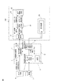
図1は、本発明の位置検出装置1を自律型移動体に適用した制御系全体を示す概略構成ブロック図である。同図に示すように、移動体100に対して取り付け可能な位置検出装置1はコンポーネント10で構成されており、移動体100の目標位置(Xg,Yg)(必要に応じて目標角度(θg))を入力する入力手段6と、移動体100の周囲環境データを取り込むレーザ距離センサ3とを設けている。移動体100に対して取り付け可能な位置検出装置1は、記録形態は特定されない記録媒体に記録された地図データ2と、この地図データ2と距離センサ3から得られた測定データとを比較照合するデータ照合手段4とから構成される位置同定手段5と、入力手段6でユーザが設定した移動体100の目標位置(Xg,Yg)(必要に応じて目標角度(θg))に対する移動体100の相対位置(必要に応じて相対角度)を演算する相対位置演算手段7と、位置同定手段5による同定結果によって得られた移動体100の位置(必要に応じて角度)を演算する絶対位置演算手段8とから構成される。これらはコンポーネント10としてユニット化されることにより、各種の移動体に取り付けることが可能である。
FIG. 1 is a schematic block diagram showing the entire control system in which the
距離センサ3は、例えば2次元レーザレンジファインダのような2次元スキャン型距離センサであり、そのレーザ光線が、左右に傾いていない平面(スキャン平面)内において、センサ取付位置を中心にして270°程度、扇状にスキャンして照射され、その反射光を受信して壁や棚などの周囲物体までの距離を計測する。地図データ2は壁や棚などの周囲物体の境界のデータから構成されている。位置同定手段5は、距離センサ3からの計測データを取り込んで地図データ2と照合し、絶対位置演算手段8によって地図上での移動体100の自己の絶対位置X,Y(必要に応じて絶対角度(θ))を演算処理し、その自己装置の絶対位置X,Y(必要に応じて絶対角度(θ))と入力手段6からの目標位置(Xg,Yg)(必要に応じて目標角度(θg))により、目標位置に対する自装置絶対位置の相対位置を演算する。
The
ユーザは、キーボードやマウスなどの入力手段6によって、目標地点の位置(Xg,Yg)(必要に応じて目標角度θg)や当該目標地点に至る経路あるいは道順など予め設定し、これを経路データとして相対位置演算手段7に入力しておく。ここでは、目標角度θgがある場合について説明する。この経路データは、移動体50が自律的に移動するのに必要となるデータであって、計画(指定)された経路における経由地点の位置(座標)や、目標地まで移動(走行)する道順や経路などや、目標地点での姿勢(角度)を示すデータにより構成される。相対位置演算手段7によって演算処理した経路データは、制御指令21(dx,dy,dθ)として自律型移動ロボット20の走行駆動手段23に出力される。自律型移動体ロボット20には、該自律型移動ロボット20を移動制御するための左右の車輪及びこの車輪をそれぞれ個別に駆動可能なモータなどから成る走行駆動手段23が備えられており、相対位置演算手段7からの制御指令21(dx,dy,dθ)を走行制御手段22に出力することによって、自律型移動体ロボット20の速度(dx,dyによる制御)や操舵角(dθによる制御)が制御され、ユーザが設定した経路を辿って目標地まで自律型移動体ロボット20を誘導することができる。
The user presets the position (Xg, Yg) of the target point (target angle θg if necessary), the route or the route to the target point, and the like as route data using the input means 6 such as a keyboard or a mouse. The relative position calculation means 7 is input. Here, a case where there is a target angle θg will be described. This route data is data necessary for the
図2を用いて、地図B上に定められた原点を基準として、スタート点G0から目標点Gnに到達する際の動作を説明する。地図B上にxb軸とyb軸の交点を地図Bの原点を設ける。地図B上の座標は(Xb,Yb,θb)で表される。角度(θb)は移動体100の姿勢(向き)を意味する値である。移動体100は、スタート点G0において水平右向きであり、スタートしてそのまま水平に装置4の前の第1経由地G1に向かい、第1経由地G1から一定の旋回半径で左に90度旋回しながら垂直上向きで第2経由地G2に至る。次に、装置1手前の第3経由地G3まで一定の旋回半径で右旋回して右に90度回転して水平右向きとなり、そのまま第3経由地G3まで進む。さらに、移動体100は装置5の横で装置3の手前の第4経由地G4まで直進した後、一定の旋回半径で左に90度旋回して垂直上向きとなり、直進して目的地Gnまで進む。移動体100は、目的地Gnでは装置3に対して水平となる姿勢を保つようにしている。移動体100は、地図Bの原点を基にしたB棟の内法と装置1乃至5の外形からなる地図データを予め記憶しており、移動体100は、サンプリングタイムごとに自己の移動体100からの周囲環境のデータを計測し、その計測データと地図データとを比較してマッチングを取りながら、自己の絶対位置と目標位置に対する相対位置を求めながら、走行を制御している。
With reference to FIG. 2, the operation when reaching the target point Gn from the start point G0 will be described with reference to the origin defined on the map B. On the map B, the intersection of the xb axis and the yb axis is set as the origin of the map B. The coordinates on the map B are represented by (Xb, Yb, θb). The angle (θb) is a value that means the posture (orientation) of the moving
以上のように、本発明の移動体100に対して取り付け可能な位置検出装置1の絶対位置演算手段8は、移動体100が移動する環境内の予め決められた地図の特定地点を原点とする座標系の絶対位置を演算処理することができる。この絶対位置演算手段8から得られた絶対座標は、移動体100の表示手段30の表示装置31上に出力することができる。これによって、移動体100の表示手段30に備えた表示装置31にて移動体100の絶対位置(X,Y座標)と、移動体100の絶対角度が表示され、目標地までのルート表示が可能となる。
As described above, the absolute position calculation means 8 of the
本発明は、以上のように、位置検出装置1をコンポーネント10としてユニット化し、各種の移動体100に取り付けることができるように構成し、その取り付けた位置検出装置1からは、移動体100に対する演算終了後の制御指令を出力するようにしたので、位置検出装置1を特定の移動体に限定されることなく、多種の移動体に取り付けることが可能となるものである。
As described above, the present invention is configured such that the
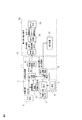
すなわち、図1では移動体として自律型移動ロボット20を示したが、例えば図3に示すように、移動体としてAGV(Automated Guided Vehicle)と称する無人搬送車50に対して位置検出装置1をコンポーネント10として取り付けることも可能であり、このようにした場合、無人搬送車50に組み込まれている走行制御手段22に対して制御指令21を出力するように変更すれば、容易に無人搬送車50の走行及び操舵角を制御して無人搬送車50を所定の経路を辿って目標地まで無軌道で誘導制御することができる。これにより、無人搬送車50の経路を変更する場合、経路に形成したガイドラインAの設置を変更することなく、単に目標地の設定を変更するだけで、簡単に無人搬送車50の経路を変更することができる。
That is, although the autonomous
図4に、経路Aに沿って移動する無人搬送車50に適用する際の実施例を示す。図1と異なる点は、入力手段6から位置検出装置1に入力される情報が、目標位置Xg,Ygだけで、目標角度θgを入力していない点である。目標角度θgは目標角度演算手段81において、目標位置Xg,Ygを用いて計算する。例えば、目標点G2の目標角度θg2は下記の式により求める。
θg2=tan-1{(Yg2−Yg1)/(Xg2−Xg1)}
つまり、1つ前の目標点G1から目標点G2までの線分の傾きで計算する。これにより、入力手段6から入力する情報は少なくすることができる。さらに、目標点G0〜Gnを設定することにより、図5に示すように、無人搬送車50が走行する経路Aを確定できる。次に、図4の相対位置演算手段7において、目標点までの相対距離dx、dyと相対角度dθを計算する点は図1と同じであるが、それを経路偏差演算手段82に入力している点が異なる。
FIG. 4 shows an embodiment when applied to the automatic guided
θg2 = tan-1 {(Yg2-Yg1) / (Xg2-Xg1)}
That is, the calculation is performed with the slope of the line segment from the previous target point G1 to the target point G2. Thereby, the information input from the input means 6 can be decreased. Furthermore, by setting the target points G0 to Gn, the route A on which the automatic guided
目標点G4に向かって走行しているときの無人搬送車50が図5に示すような状態にあるとすると、経路Aからの位置ずれdは目標点G4からの相対距離dyに相当するので、それを選択することにより、位置ずれdを求めることができる。また、経路Aに対する角度ずれγは相対角度dθに相当するので、それを選択して角度ずれγとして出力している。これを無人搬送車50の走行制御手段22に制御指令21を出力することで、従来の無人搬送車と同じ制御を実現する。位置検出装置1を入れ替えるだけで、従来、現場に設置していた磁気テープやマーカーなどを必要とすることなく、同一の制御方法で無人搬送車を走行することができるので、柔軟性を有するシステムを構築できる利点がある。
If the automated guided
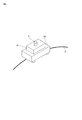
また、図6に示すように、移動体として例えば病院内においてリハビリ用などに用いる介護用歩行器60(手動型移動体)に適用し、絶対位置演算手段8から介護用歩行器60に設けた表示装置31に自己の絶対位置を表示すれば、予め指定されたルートを通って介護用歩行器60の介助を受けながら歩行するような場合、その設定したルートに従って介護用歩行器60が進む方向を表示してユーザを誘導することができる。これにより、表示装置31によりユーザを目標地まで視覚的に誘導しながら歩行を介助することができる。
Further, as shown in FIG. 6, the moving body is applied to a nursing walker 60 (manual movable body) used for rehabilitation in a hospital, for example, and provided from the absolute position calculation means 8 to the
この場合には、介護用歩行器60は、走行のための動力を備えることは安全上問題がある。詳細には説明しないが、自走する車輪にエンコーダを備えておき、相対位置演算手段からの制御指令に従って自走しているか否かの監視に使うことができる。また、目的と相違した方向に走行しようとした場合には制動力を発揮することも可能である。
In this case, it is a safety problem that the
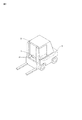
さらに、図7に示すように、移動体として運転者が運転する自走式のフォークリフト70に適用した場合でも、絶対位置演算手段8からのフォークリフト70に設けた表示装置31に情報が出力すれば、工場・物流倉庫などにおいて、予め設定したルートに従ってフォークリフト70が進む方向を運転者に表示して誘導することができる。
Furthermore, as shown in FIG. 7, even when applied to a self-propelled
本発明においては、以上のように、位置検出装置1をコンポーネント10としてユニット化し、自律式、自走型、手動型といった各種の移動体に取り付けることが可能であり、汎用性に優れるとともに、位置検出装置1自体には、移動体の走行駆動系を制御するための構成も不要となり、構成も簡略化することができる。
In the present invention, as described above, the
1 位置検出装置
2 地図データ
3 距離センサ
4 位置同定手段
6 入力手段
7 相対位置演算手段
8 絶対位置演算手段
10 位置同定コンポーネント
20 自律型移動ロボット(移動体)
30 表示手段
31 表示装置
50 無人搬送車(移動体)
60 介護用歩行器(移動体)
70 フォークリフト(移動体)
82 経路偏差演算手段
100 移動体
DESCRIPTION OF
30 Display means 31
60 Walking walker (moving body)
70 Forklift (moving body)
82 Route deviation calculating means 100 Mobile
Claims (9)
当該移動体を取り巻く周囲環境の地図情報と当該距離センサから得られた情報を用いて、当該移動体の位置と角度を同定する位置同定手段と、前記入力手段により設定した当該移動体の目標位置と目標角度に対する当該移動体の相対位置と相対角度を演算する相対位置演算手段とを内蔵しており、前記位置同定手段の同定結果と前記相対位置演算手段の演算結果とに基づいて当該移動体の走行制御手段に対して制御指令を出力する位置検出装置を取り付けたことを特徴とする移動体。 An input means for inputting a moving target position of the moving body, and a distance sensor for measuring a distance from the moving body to the surrounding environment;
Using the map information of the surrounding environment surrounding the moving body and the information obtained from the distance sensor, position identifying means for identifying the position and angle of the moving body, and the target position of the moving body set by the input means And a relative position calculating means for calculating a relative position of the moving body with respect to a target angle and a relative angle, and the moving body based on the identification result of the position identifying means and the calculation result of the relative position calculating means. A moving body comprising a position detection device for outputting a control command to the travel control means.
Identifying the position and angle of the moving body using the input means for inputting the target route of the moving body, the information obtained from the distance sensor for measuring the distance from the moving body to the surrounding environment, and the map information of the surrounding environment And a relative path calculation means for calculating a relative distance and a relative angle of the moving body with respect to the target path, and outputs an identification result of the position identification means and a calculation result of the relative path calculation means. A position detecting device characterized by that.
Priority Applications (4)
| Application Number | Priority Date | Filing Date | Title |
|---|---|---|---|
| JP2013068049A JP2014191689A (en) | 2013-03-28 | 2013-03-28 | Traveling object attached with position detection device for outputting control command to travel control means of traveling object and position detection device |
| US14/778,314 US10261511B2 (en) | 2013-03-28 | 2014-03-04 | Mobile body and position detection device |
| CN201480018919.1A CN105190461A (en) | 2013-03-28 | 2014-03-04 | Mobile body and position detection device |
| PCT/JP2014/055361 WO2014156498A1 (en) | 2013-03-28 | 2014-03-04 | Mobile body and position detection device |
Applications Claiming Priority (1)
| Application Number | Priority Date | Filing Date | Title |
|---|---|---|---|
| JP2013068049A JP2014191689A (en) | 2013-03-28 | 2013-03-28 | Traveling object attached with position detection device for outputting control command to travel control means of traveling object and position detection device |
Related Child Applications (1)
| Application Number | Title | Priority Date | Filing Date |
|---|---|---|---|
| JP2017112373A Division JP2017152051A (en) | 2017-06-07 | 2017-06-07 | Traveling object attached with position detection device for outputting control command to travel control means of traveling object, and position detection device of the same |
Publications (2)
| Publication Number | Publication Date |
|---|---|
| JP2014191689A true JP2014191689A (en) | 2014-10-06 |
| JP2014191689A5 JP2014191689A5 (en) | 2016-02-18 |
Family
ID=51623488
Family Applications (1)
| Application Number | Title | Priority Date | Filing Date |
|---|---|---|---|
| JP2013068049A Pending JP2014191689A (en) | 2013-03-28 | 2013-03-28 | Traveling object attached with position detection device for outputting control command to travel control means of traveling object and position detection device |
Country Status (4)
| Country | Link |
|---|---|
| US (1) | US10261511B2 (en) |
| JP (1) | JP2014191689A (en) |
| CN (1) | CN105190461A (en) |
| WO (1) | WO2014156498A1 (en) |
Cited By (4)
| Publication number | Priority date | Publication date | Assignee | Title |
|---|---|---|---|---|
| WO2017134805A1 (en) * | 2016-02-05 | 2017-08-10 | 株式会社日立産機システム | Position detecting device, control device and moving body |
| CN107169611A (en) * | 2017-06-09 | 2017-09-15 | 金陵科技学院 | A kind of patterned way planning AGV travel regions and the method for monitoring its operation |
| CN107766859A (en) * | 2017-10-31 | 2018-03-06 | 广东美的智能机器人有限公司 | Method for positioning mobile robot, device and mobile robot |
| WO2019065431A1 (en) | 2017-09-28 | 2019-04-04 | Sony Corporation | Information processing apparatus, movable apparatus, information processing method, movable-apparatus control method, and programs |
Families Citing this family (12)
| Publication number | Priority date | Publication date | Assignee | Title |
|---|---|---|---|---|
| GB201409883D0 (en) | 2014-06-03 | 2014-07-16 | Ocado Ltd | Methods, systems, and apparatus for controlling movement of transporting devices |
| US10031528B2 (en) | 2016-02-01 | 2018-07-24 | Komatsu Ltd. | Work machine control system, work machine, and work machine management system |
| CN106527434A (en) * | 2016-11-07 | 2017-03-22 | 北京京东尚科信息技术有限公司 | Automatic transfer system and method |
| CN106843229B (en) * | 2017-03-24 | 2020-11-10 | 上海思岚科技有限公司 | Virtual track design system for mobile equipment and implementation method thereof |
| CN108152827B (en) * | 2017-09-28 | 2020-09-18 | 北京卫星制造厂 | Omnidirectional intelligent mobile equipment positioning and navigation method based on laser ranging |
| JP2019086812A (en) * | 2017-11-01 | 2019-06-06 | 株式会社日立産機システム | Mobile body system |
| US10409287B2 (en) * | 2017-11-30 | 2019-09-10 | Komatsu America Corp. | Vehicle guide display and path navigation method |
| US20200017124A1 (en) * | 2018-07-12 | 2020-01-16 | Sf Motors, Inc. | Adaptive driver monitoring for advanced driver-assistance systems |
| JP7267691B2 (en) * | 2018-07-20 | 2023-05-02 | 株式会社日立製作所 | Mobile positioning system and mobile positioning method |
| JP7239291B2 (en) * | 2018-09-28 | 2023-03-14 | 株式会社小松製作所 | Work vehicle surroundings monitoring system and work vehicle surroundings monitoring method |
| CA3225797A1 (en) | 2020-02-21 | 2021-08-26 | Crown Equipment Corporation | Modify vehicle parameter based on vehicle position information |
| JP7085576B2 (en) * | 2020-02-27 | 2022-06-16 | 三菱ロジスネクスト株式会社 | Mobile control systems, mobiles, control methods and programs |
Citations (7)
| Publication number | Priority date | Publication date | Assignee | Title |
|---|---|---|---|---|
| JPH10207504A (en) * | 1997-01-20 | 1998-08-07 | Komatsu Ltd | Artificial intelligence machine and artificial intelligence machine system |
| JP2006007368A (en) * | 2004-06-25 | 2006-01-12 | Funai Electric Co Ltd | Self-propelled vacuum cleaner |
| JP2011175393A (en) * | 2010-02-24 | 2011-09-08 | Toyota Motor Corp | Route planning apparatus, autonomous mobile robot, and method for planning movement path |
| JP2011248648A (en) * | 2010-05-27 | 2011-12-08 | Toyota Central R&D Labs Inc | Moving body |
| JP2012022468A (en) * | 2010-07-13 | 2012-02-02 | Murata Mach Ltd | Autonomous mobile body |
| JP2012105557A (en) * | 2010-11-15 | 2012-06-07 | Original Soft:Kk | Automatic lawn mower |
| JP2012138086A (en) * | 2005-09-30 | 2012-07-19 | Irobot Corp | Companion robot for personal interaction |
Family Cites Families (16)
| Publication number | Priority date | Publication date | Assignee | Title |
|---|---|---|---|---|
| CN1055772C (en) * | 1995-12-01 | 2000-08-23 | 三星电子株式会社 | Environment recognition apparatus of robot and control method thereof |
| WO1997036217A1 (en) | 1996-03-22 | 1997-10-02 | Hitachi, Ltd. | Method and apparatus for controlling operation of moving mechanism |
| JP4229358B2 (en) * | 2001-01-22 | 2009-02-25 | 株式会社小松製作所 | Driving control device for unmanned vehicles |
| DE10254403A1 (en) * | 2002-11-21 | 2004-06-03 | Lucas Automotive Gmbh | System for influencing the speed of a motor vehicle |
| EP1677125A1 (en) * | 2004-12-28 | 2006-07-05 | Leica Geosystems AG | Method and rotative laser for determining a positional information of at least one object |
| DE102006027326A1 (en) * | 2006-06-13 | 2007-12-20 | Robert Bosch Gmbh | Lane change assistant for motor vehicles |
| US20080243378A1 (en) * | 2007-02-21 | 2008-10-02 | Tele Atlas North America, Inc. | System and method for vehicle navigation and piloting including absolute and relative coordinates |
| WO2010038353A1 (en) * | 2008-10-01 | 2010-04-08 | 村田機械株式会社 | Autonomous movement device |
| JP2010095146A (en) | 2008-10-16 | 2010-04-30 | Toyota Industries Corp | Automatic guided vehicle |
| JP4962742B2 (en) | 2008-12-11 | 2012-06-27 | 株式会社安川電機 | Mobile system |
| IL200921A (en) * | 2009-09-14 | 2016-05-31 | Israel Aerospace Ind Ltd | Infantry robotic porter system and methods useful in conjunction therewith |
| JP5503419B2 (en) | 2010-06-03 | 2014-05-28 | 株式会社日立製作所 | Automated guided vehicle and travel control method |
| FR2993376B1 (en) * | 2012-07-12 | 2014-07-25 | Renault Sa | METHOD FOR CONTROLLING THE TRACK OF AN AUTONOMOUS VEHICLE WITH STEERING WHEELS |
| JP2014174447A (en) * | 2013-03-12 | 2014-09-22 | Japan Automobile Research Institute | Vehicle dangerous scene reproducer, and method of use thereof |
| US8965561B2 (en) * | 2013-03-15 | 2015-02-24 | Cybernet Systems Corporation | Automated warehousing using robotic forklifts |
| KR101519266B1 (en) * | 2013-12-18 | 2015-05-11 | 현대자동차주식회사 | Method for estimating indoor position of vehicle |
-
2013
- 2013-03-28 JP JP2013068049A patent/JP2014191689A/en active Pending
-
2014
- 2014-03-04 WO PCT/JP2014/055361 patent/WO2014156498A1/en active Application Filing
- 2014-03-04 US US14/778,314 patent/US10261511B2/en active Active
- 2014-03-04 CN CN201480018919.1A patent/CN105190461A/en active Pending
Patent Citations (7)
| Publication number | Priority date | Publication date | Assignee | Title |
|---|---|---|---|---|
| JPH10207504A (en) * | 1997-01-20 | 1998-08-07 | Komatsu Ltd | Artificial intelligence machine and artificial intelligence machine system |
| JP2006007368A (en) * | 2004-06-25 | 2006-01-12 | Funai Electric Co Ltd | Self-propelled vacuum cleaner |
| JP2012138086A (en) * | 2005-09-30 | 2012-07-19 | Irobot Corp | Companion robot for personal interaction |
| JP2011175393A (en) * | 2010-02-24 | 2011-09-08 | Toyota Motor Corp | Route planning apparatus, autonomous mobile robot, and method for planning movement path |
| JP2011248648A (en) * | 2010-05-27 | 2011-12-08 | Toyota Central R&D Labs Inc | Moving body |
| JP2012022468A (en) * | 2010-07-13 | 2012-02-02 | Murata Mach Ltd | Autonomous mobile body |
| JP2012105557A (en) * | 2010-11-15 | 2012-06-07 | Original Soft:Kk | Automatic lawn mower |
Cited By (5)
| Publication number | Priority date | Publication date | Assignee | Title |
|---|---|---|---|---|
| WO2017134805A1 (en) * | 2016-02-05 | 2017-08-10 | 株式会社日立産機システム | Position detecting device, control device and moving body |
| CN107169611A (en) * | 2017-06-09 | 2017-09-15 | 金陵科技学院 | A kind of patterned way planning AGV travel regions and the method for monitoring its operation |
| WO2019065431A1 (en) | 2017-09-28 | 2019-04-04 | Sony Corporation | Information processing apparatus, movable apparatus, information processing method, movable-apparatus control method, and programs |
| KR20200062193A (en) | 2017-09-28 | 2020-06-03 | 소니 주식회사 | Information processing device, mobile device, information processing method, mobile device control method, and program |
| CN107766859A (en) * | 2017-10-31 | 2018-03-06 | 广东美的智能机器人有限公司 | Method for positioning mobile robot, device and mobile robot |
Also Published As
| Publication number | Publication date |
|---|---|
| CN105190461A (en) | 2015-12-23 |
| WO2014156498A1 (en) | 2014-10-02 |
| US20160062357A1 (en) | 2016-03-03 |
| US10261511B2 (en) | 2019-04-16 |
Similar Documents
| Publication | Publication Date | Title |
|---|---|---|
| WO2014156498A1 (en) | Mobile body and position detection device | |
| US9244463B2 (en) | Automated guided vehicle and method of operating an automated guided vehicle | |
| JP6492024B2 (en) | Moving body | |
| JP6599543B2 (en) | Automated guided vehicle | |
| KR101526639B1 (en) | Automatic guided vehicle and travel control method | |
| JP4910219B2 (en) | Autonomous moving method and autonomous moving body | |
| JP2006227673A (en) | Autonomous travel device | |
| US20060276958A1 (en) | Inertial navigational guidance system for a driverless vehicle utilizing laser obstacle sensors | |
| JP6083520B2 (en) | Robot guidance method and apparatus | |
| Wang et al. | High accuracy mobile robot positioning using external large volume metrology instruments | |
| JP2012014265A (en) | Movable body | |
| JP2007213356A (en) | Automated guided facility | |
| JP5561730B2 (en) | Guidance control system and guidance control method for moving body | |
| JP2015055906A (en) | Position detection device for outputting control command to travel control means of moving body and moving body system | |
| de Lima et al. | A visual servoing approach for road lane following with obstacle avoidance | |
| JP2017152051A (en) | Traveling object attached with position detection device for outputting control command to travel control means of traveling object, and position detection device of the same | |
| WO2016072186A1 (en) | Location detecting device, control method, and autonomous vehicle | |
| JP2019079171A (en) | Movable body | |
| JP2010262461A (en) | Mobile object | |
| Juntao et al. | Research of AGV positioning based on the two-dimensional Code Recognition Method | |
| JP2018039310A (en) | Passenger boarding bridge | |
| CN110888427A (en) | Automatic traveling trolley control system with track memory function and control method thereof | |
| JP2009223632A (en) | Autonomous mobile device and autonomous mobile device system | |
| JP2016009246A (en) | Environmental map generation controller, mobile body and environmental map generation method | |
| JP6784138B2 (en) | Parking support method and parking support device |
Legal Events
| Date | Code | Title | Description |
|---|---|---|---|
| A521 | Request for written amendment filed |
Free format text: JAPANESE INTERMEDIATE CODE: A523 Effective date: 20151224 |
|
| A621 | Written request for application examination |
Free format text: JAPANESE INTERMEDIATE CODE: A621 Effective date: 20151224 |
|
| A131 | Notification of reasons for refusal |
Free format text: JAPANESE INTERMEDIATE CODE: A131 Effective date: 20160802 |
|
| A521 | Request for written amendment filed |
Free format text: JAPANESE INTERMEDIATE CODE: A523 Effective date: 20160923 |
|
| A02 | Decision of refusal |
Free format text: JAPANESE INTERMEDIATE CODE: A02 Effective date: 20170307 |