EP4278940A2 - Device for cleaning dirty surfaces - Google Patents
Device for cleaning dirty surfaces Download PDFInfo
- Publication number
- EP4278940A2 EP4278940A2 EP23201753.3A EP23201753A EP4278940A2 EP 4278940 A2 EP4278940 A2 EP 4278940A2 EP 23201753 A EP23201753 A EP 23201753A EP 4278940 A2 EP4278940 A2 EP 4278940A2
- Authority
- EP
- European Patent Office
- Prior art keywords
- dirt
- sensor
- emptying
- area
- cleaning
- Prior art date
- Legal status (The legal status is an assumption and is not a legal conclusion. Google has not performed a legal analysis and makes no representation as to the accuracy of the status listed.)
- Pending
Links
- 238000004140 cleaning Methods 0.000 title claims abstract description 43
- 230000008859 change Effects 0.000 claims abstract description 17
- 230000000694 effects Effects 0.000 claims abstract description 10
- 238000000034 method Methods 0.000 claims description 30
- 230000003287 optical effect Effects 0.000 claims description 21
- 238000001514 detection method Methods 0.000 claims description 13
- 230000009471 action Effects 0.000 claims description 9
- 230000008569 process Effects 0.000 claims description 6
- 238000007664 blowing Methods 0.000 claims description 5
- 238000001914 filtration Methods 0.000 claims description 4
- 230000004807 localization Effects 0.000 claims description 4
- 238000005259 measurement Methods 0.000 claims description 4
- 238000010408 sweeping Methods 0.000 claims description 4
- 235000004443 Ricinus communis Nutrition 0.000 claims description 3
- 239000000428 dust Substances 0.000 claims description 3
- 240000000528 Ricinus communis Species 0.000 claims description 2
- 238000003032 molecular docking Methods 0.000 claims description 2
- 239000002245 particle Substances 0.000 claims description 2
- 230000008901 benefit Effects 0.000 description 5
- 238000010586 diagram Methods 0.000 description 3
- 230000007246 mechanism Effects 0.000 description 3
- 230000001133 acceleration Effects 0.000 description 2
- 230000001960 triggered effect Effects 0.000 description 2
- 238000010276 construction Methods 0.000 description 1
- 230000008878 coupling Effects 0.000 description 1
- 238000010168 coupling process Methods 0.000 description 1
- 238000005859 coupling reaction Methods 0.000 description 1
- 238000006073 displacement reaction Methods 0.000 description 1
- 239000003344 environmental pollutant Substances 0.000 description 1
- 230000001939 inductive effect Effects 0.000 description 1
- 231100000719 pollutant Toxicity 0.000 description 1
- 239000002689 soil Substances 0.000 description 1
- 230000000007 visual effect Effects 0.000 description 1
Images


Classifications
-
- A—HUMAN NECESSITIES
- A47—FURNITURE; DOMESTIC ARTICLES OR APPLIANCES; COFFEE MILLS; SPICE MILLS; SUCTION CLEANERS IN GENERAL
- A47L—DOMESTIC WASHING OR CLEANING; SUCTION CLEANERS IN GENERAL
- A47L9/00—Details or accessories of suction cleaners, e.g. mechanical means for controlling the suction or for effecting pulsating action; Storing devices specially adapted to suction cleaners or parts thereof; Carrying-vehicles specially adapted for suction cleaners
- A47L9/28—Installation of the electric equipment, e.g. adaptation or attachment to the suction cleaner; Controlling suction cleaners by electric means
- A47L9/2805—Parameters or conditions being sensed
- A47L9/2826—Parameters or conditions being sensed the condition of the floor
-
- A—HUMAN NECESSITIES
- A47—FURNITURE; DOMESTIC ARTICLES OR APPLIANCES; COFFEE MILLS; SPICE MILLS; SUCTION CLEANERS IN GENERAL
- A47L—DOMESTIC WASHING OR CLEANING; SUCTION CLEANERS IN GENERAL
- A47L11/00—Machines for cleaning floors, carpets, furniture, walls, or wall coverings
- A47L11/40—Parts or details of machines not provided for in groups A47L11/02 - A47L11/38, or not restricted to one of these groups, e.g. handles, arrangements of switches, skirts, buffers, levers
- A47L11/4061—Steering means; Means for avoiding obstacles; Details related to the place where the driver is accommodated
-
- A—HUMAN NECESSITIES
- A47—FURNITURE; DOMESTIC ARTICLES OR APPLIANCES; COFFEE MILLS; SPICE MILLS; SUCTION CLEANERS IN GENERAL
- A47L—DOMESTIC WASHING OR CLEANING; SUCTION CLEANERS IN GENERAL
- A47L11/00—Machines for cleaning floors, carpets, furniture, walls, or wall coverings
- A47L11/24—Floor-sweeping machines, motor-driven
-
- A—HUMAN NECESSITIES
- A47—FURNITURE; DOMESTIC ARTICLES OR APPLIANCES; COFFEE MILLS; SPICE MILLS; SUCTION CLEANERS IN GENERAL
- A47L—DOMESTIC WASHING OR CLEANING; SUCTION CLEANERS IN GENERAL
- A47L11/00—Machines for cleaning floors, carpets, furniture, walls, or wall coverings
- A47L11/29—Floor-scrubbing machines characterised by means for taking-up dirty liquid
- A47L11/30—Floor-scrubbing machines characterised by means for taking-up dirty liquid by suction
- A47L11/302—Floor-scrubbing machines characterised by means for taking-up dirty liquid by suction having rotary tools
- A47L11/305—Floor-scrubbing machines characterised by means for taking-up dirty liquid by suction having rotary tools the tools being disc brushes
-
- A—HUMAN NECESSITIES
- A47—FURNITURE; DOMESTIC ARTICLES OR APPLIANCES; COFFEE MILLS; SPICE MILLS; SUCTION CLEANERS IN GENERAL
- A47L—DOMESTIC WASHING OR CLEANING; SUCTION CLEANERS IN GENERAL
- A47L11/00—Machines for cleaning floors, carpets, furniture, walls, or wall coverings
- A47L11/40—Parts or details of machines not provided for in groups A47L11/02 - A47L11/38, or not restricted to one of these groups, e.g. handles, arrangements of switches, skirts, buffers, levers
- A47L11/4002—Installations of electric equipment
- A47L11/4008—Arrangements of switches, indicators or the like
-
- A—HUMAN NECESSITIES
- A47—FURNITURE; DOMESTIC ARTICLES OR APPLIANCES; COFFEE MILLS; SPICE MILLS; SUCTION CLEANERS IN GENERAL
- A47L—DOMESTIC WASHING OR CLEANING; SUCTION CLEANERS IN GENERAL
- A47L11/00—Machines for cleaning floors, carpets, furniture, walls, or wall coverings
- A47L11/40—Parts or details of machines not provided for in groups A47L11/02 - A47L11/38, or not restricted to one of these groups, e.g. handles, arrangements of switches, skirts, buffers, levers
- A47L11/4011—Regulation of the cleaning machine by electric means; Control systems and remote control systems therefor
-
- A—HUMAN NECESSITIES
- A47—FURNITURE; DOMESTIC ARTICLES OR APPLIANCES; COFFEE MILLS; SPICE MILLS; SUCTION CLEANERS IN GENERAL
- A47L—DOMESTIC WASHING OR CLEANING; SUCTION CLEANERS IN GENERAL
- A47L11/00—Machines for cleaning floors, carpets, furniture, walls, or wall coverings
- A47L11/40—Parts or details of machines not provided for in groups A47L11/02 - A47L11/38, or not restricted to one of these groups, e.g. handles, arrangements of switches, skirts, buffers, levers
- A47L11/4072—Arrangement of castors or wheels
-
- A—HUMAN NECESSITIES
- A47—FURNITURE; DOMESTIC ARTICLES OR APPLIANCES; COFFEE MILLS; SPICE MILLS; SUCTION CLEANERS IN GENERAL
- A47L—DOMESTIC WASHING OR CLEANING; SUCTION CLEANERS IN GENERAL
- A47L7/00—Suction cleaners adapted for additional purposes; Tables with suction openings for cleaning purposes; Containers for cleaning articles by suction; Suction cleaners adapted to cleaning of brushes; Suction cleaners adapted to taking-up liquids
- A47L7/04—Suction cleaners adapted for additional purposes; Tables with suction openings for cleaning purposes; Containers for cleaning articles by suction; Suction cleaners adapted to cleaning of brushes; Suction cleaners adapted to taking-up liquids for using the exhaust air for other purposes, e.g. for distribution of chemicals in a room, for sterilisation of the air
-
- A—HUMAN NECESSITIES
- A47—FURNITURE; DOMESTIC ARTICLES OR APPLIANCES; COFFEE MILLS; SPICE MILLS; SUCTION CLEANERS IN GENERAL
- A47L—DOMESTIC WASHING OR CLEANING; SUCTION CLEANERS IN GENERAL
- A47L9/00—Details or accessories of suction cleaners, e.g. mechanical means for controlling the suction or for effecting pulsating action; Storing devices specially adapted to suction cleaners or parts thereof; Carrying-vehicles specially adapted for suction cleaners
- A47L9/009—Carrying-vehicles; Arrangements of trollies or wheels; Means for avoiding mechanical obstacles
-
- A—HUMAN NECESSITIES
- A47—FURNITURE; DOMESTIC ARTICLES OR APPLIANCES; COFFEE MILLS; SPICE MILLS; SUCTION CLEANERS IN GENERAL
- A47L—DOMESTIC WASHING OR CLEANING; SUCTION CLEANERS IN GENERAL
- A47L9/00—Details or accessories of suction cleaners, e.g. mechanical means for controlling the suction or for effecting pulsating action; Storing devices specially adapted to suction cleaners or parts thereof; Carrying-vehicles specially adapted for suction cleaners
- A47L9/10—Filters; Dust separators; Dust removal; Automatic exchange of filters
- A47L9/16—Arrangement or disposition of cyclones or other devices with centrifugal action
- A47L9/1683—Dust collecting chambers; Dust collecting receptacles
-
- A—HUMAN NECESSITIES
- A47—FURNITURE; DOMESTIC ARTICLES OR APPLIANCES; COFFEE MILLS; SPICE MILLS; SUCTION CLEANERS IN GENERAL
- A47L—DOMESTIC WASHING OR CLEANING; SUCTION CLEANERS IN GENERAL
- A47L9/00—Details or accessories of suction cleaners, e.g. mechanical means for controlling the suction or for effecting pulsating action; Storing devices specially adapted to suction cleaners or parts thereof; Carrying-vehicles specially adapted for suction cleaners
- A47L9/10—Filters; Dust separators; Dust removal; Automatic exchange of filters
- A47L9/16—Arrangement or disposition of cyclones or other devices with centrifugal action
- A47L9/1691—Mounting or coupling means for cyclonic chamber or dust receptacles
-
- A—HUMAN NECESSITIES
- A47—FURNITURE; DOMESTIC ARTICLES OR APPLIANCES; COFFEE MILLS; SPICE MILLS; SUCTION CLEANERS IN GENERAL
- A47L—DOMESTIC WASHING OR CLEANING; SUCTION CLEANERS IN GENERAL
- A47L9/00—Details or accessories of suction cleaners, e.g. mechanical means for controlling the suction or for effecting pulsating action; Storing devices specially adapted to suction cleaners or parts thereof; Carrying-vehicles specially adapted for suction cleaners
- A47L9/28—Installation of the electric equipment, e.g. adaptation or attachment to the suction cleaner; Controlling suction cleaners by electric means
- A47L9/2805—Parameters or conditions being sensed
- A47L9/281—Parameters or conditions being sensed the amount or condition of incoming dirt or dust
- A47L9/2815—Parameters or conditions being sensed the amount or condition of incoming dirt or dust using optical detectors
-
- A—HUMAN NECESSITIES
- A47—FURNITURE; DOMESTIC ARTICLES OR APPLIANCES; COFFEE MILLS; SPICE MILLS; SUCTION CLEANERS IN GENERAL
- A47L—DOMESTIC WASHING OR CLEANING; SUCTION CLEANERS IN GENERAL
- A47L9/00—Details or accessories of suction cleaners, e.g. mechanical means for controlling the suction or for effecting pulsating action; Storing devices specially adapted to suction cleaners or parts thereof; Carrying-vehicles specially adapted for suction cleaners
- A47L9/28—Installation of the electric equipment, e.g. adaptation or attachment to the suction cleaner; Controlling suction cleaners by electric means
- A47L9/2836—Installation of the electric equipment, e.g. adaptation or attachment to the suction cleaner; Controlling suction cleaners by electric means characterised by the parts which are controlled
- A47L9/2842—Suction motors or blowers
-
- A—HUMAN NECESSITIES
- A47—FURNITURE; DOMESTIC ARTICLES OR APPLIANCES; COFFEE MILLS; SPICE MILLS; SUCTION CLEANERS IN GENERAL
- A47L—DOMESTIC WASHING OR CLEANING; SUCTION CLEANERS IN GENERAL
- A47L9/00—Details or accessories of suction cleaners, e.g. mechanical means for controlling the suction or for effecting pulsating action; Storing devices specially adapted to suction cleaners or parts thereof; Carrying-vehicles specially adapted for suction cleaners
- A47L9/28—Installation of the electric equipment, e.g. adaptation or attachment to the suction cleaner; Controlling suction cleaners by electric means
- A47L9/2836—Installation of the electric equipment, e.g. adaptation or attachment to the suction cleaner; Controlling suction cleaners by electric means characterised by the parts which are controlled
- A47L9/2847—Surface treating elements
-
- A—HUMAN NECESSITIES
- A47—FURNITURE; DOMESTIC ARTICLES OR APPLIANCES; COFFEE MILLS; SPICE MILLS; SUCTION CLEANERS IN GENERAL
- A47L—DOMESTIC WASHING OR CLEANING; SUCTION CLEANERS IN GENERAL
- A47L9/00—Details or accessories of suction cleaners, e.g. mechanical means for controlling the suction or for effecting pulsating action; Storing devices specially adapted to suction cleaners or parts thereof; Carrying-vehicles specially adapted for suction cleaners
- A47L9/28—Installation of the electric equipment, e.g. adaptation or attachment to the suction cleaner; Controlling suction cleaners by electric means
- A47L9/2836—Installation of the electric equipment, e.g. adaptation or attachment to the suction cleaner; Controlling suction cleaners by electric means characterised by the parts which are controlled
- A47L9/2852—Elements for displacement of the vacuum cleaner or the accessories therefor, e.g. wheels, casters or nozzles
-
- A—HUMAN NECESSITIES
- A47—FURNITURE; DOMESTIC ARTICLES OR APPLIANCES; COFFEE MILLS; SPICE MILLS; SUCTION CLEANERS IN GENERAL
- A47L—DOMESTIC WASHING OR CLEANING; SUCTION CLEANERS IN GENERAL
- A47L9/00—Details or accessories of suction cleaners, e.g. mechanical means for controlling the suction or for effecting pulsating action; Storing devices specially adapted to suction cleaners or parts thereof; Carrying-vehicles specially adapted for suction cleaners
- A47L9/28—Installation of the electric equipment, e.g. adaptation or attachment to the suction cleaner; Controlling suction cleaners by electric means
- A47L9/30—Arrangement of illuminating devices
-
- G—PHYSICS
- G01—MEASURING; TESTING
- G01B—MEASURING LENGTH, THICKNESS OR SIMILAR LINEAR DIMENSIONS; MEASURING ANGLES; MEASURING AREAS; MEASURING IRREGULARITIES OF SURFACES OR CONTOURS
- G01B5/00—Measuring arrangements characterised by the use of mechanical techniques
- G01B5/18—Measuring arrangements characterised by the use of mechanical techniques for measuring depth
-
- A—HUMAN NECESSITIES
- A47—FURNITURE; DOMESTIC ARTICLES OR APPLIANCES; COFFEE MILLS; SPICE MILLS; SUCTION CLEANERS IN GENERAL
- A47L—DOMESTIC WASHING OR CLEANING; SUCTION CLEANERS IN GENERAL
- A47L2201/00—Robotic cleaning machines, i.e. with automatic control of the travelling movement or the cleaning operation
- A47L2201/04—Automatic control of the travelling movement; Automatic obstacle detection
-
- A—HUMAN NECESSITIES
- A47—FURNITURE; DOMESTIC ARTICLES OR APPLIANCES; COFFEE MILLS; SPICE MILLS; SUCTION CLEANERS IN GENERAL
- A47L—DOMESTIC WASHING OR CLEANING; SUCTION CLEANERS IN GENERAL
- A47L2201/00—Robotic cleaning machines, i.e. with automatic control of the travelling movement or the cleaning operation
- A47L2201/06—Control of the cleaning action for autonomous devices; Automatic detection of the surface condition before, during or after cleaning
Abstract
Ein Gerät (1) zur selbsttätigen Ausführung einer Tätigkeit, insbesondere zur Reinigung verschmutzter Oberflächen, weist mindestens einen Sensor (3) und wenigstens ein Antriebselement (4) auf. Das Antriebselement (4) teilt das Gerät (1), bezogen auf die bestimmungsgemässe Bewegungsrichtung (B), in einen hinteren Bereich (11) und in einen vorderen Bereich (12). Der Sensor (3) ist ein mechanischer Sensor, der durch Kontakt mit dem Boden zur Feststellung einer Veränderung des Niveaus des Bodens dient und im vorderen Bereich (12) des Geräts (1) angeordnet ist.A device (1) for automatically carrying out an activity, in particular for cleaning dirty surfaces, has at least one sensor (3) and at least one drive element (4). The drive element (4) divides the device (1), based on the intended direction of movement (B), into a rear area (11) and a front area (12). The sensor (3) is a mechanical sensor which is used to detect a change in the level of the ground through contact with the ground and is arranged in the front area (12) of the device (1).
Description
Die Erfindung betrifft ein Gerät und ein Verfahren zur selbsttätigen Ausführung einer Tätigkeit, insbesondere zur Reinigung verschmutzter Oberflächen, gemäss dem Oberbegriff der unabhängigen Ansprüche.The invention relates to a device and a method for automatically carrying out an activity, in particular for cleaning dirty surfaces, according to the preamble of the independent claims.
Aus dem Stand der Technik sind verschiedene Geräte zur selbsttätigen Ausführung einer Tätigkeit bekannt, die insbesondere zur Reinigung verschmutzter Oberflächen verwendet werden. Zweck der Geräte ist es, die auszuführende Tätigkeit für den Menschen zu erleichtern. Dafür müssen die Geräte selbsttätig navigieren, Hindernisse erkennen und die auszuführende Tätigkeit selbsttätig ausführen können. Eine besondere Herausforderung ist das Vermeiden von Abstürzen über Kanten.Various devices for automatically carrying out an activity are known from the prior art, which are used in particular for cleaning dirty surfaces. The purpose of the devices is to make the task to be carried out easier for people. To do this, the devices must be able to navigate automatically, recognize obstacles and carry out the activity to be carried out independently. A particular challenge is avoiding falls over edges.
Aus
Nachteilig am Stand der Technik ist, dass das Gerät nicht in einer Umgebung mit Staubemissionen verwendet werden kann, da der Infrarotsensor gegenüber Staubemissionen fehleranfällig ist.A disadvantage of the prior art is that the device cannot be used in an environment with dust emissions because the infrared sensor is susceptible to errors in dust emissions.
Aus der
Der Nachteil hier ist, dass ein Absturz des Geräts nicht zuverlässig verhindert werden kann.The disadvantage here is that a crash of the device cannot be reliably prevented.
Es ist die Aufgabe der vorliegenden Erfindung, ein Gerät zur selbsttätigen Ausführung einer Tätigkeit zu schaffen, welches die Nachteile des Stands der Technik vermeidet und insbesondere ein Gerät und ein Verfahren zur selbsttätigen Ausführung einer Tätigkeit zu schaffen, so dass ein Absturz des Geräts in einer Umgebung mit Schmutzemissionen vermieden wird.It is the object of the present invention to create a device for automatically carrying out an activity which avoids the disadvantages of the prior art and in particular to create a device and a method for automatically carrying out an activity so that the device cannot crash in an environment with dirt emissions is avoided.
Diese Aufgabe wird durch ein Gerät und ein Verfahren zur selbsttätigen Ausführung einer Tätigkeit, insbesondere zur Reinigung verschmutzter Oberflächen, gemäss den unabhängigen Ansprüchen gelöst.This task is solved by a device and a method for automatically carrying out an activity, in particular for cleaning dirty surfaces, according to the independent claims.
Erfindungsgemäss umfasst das Gerät zur selbsttätigen Ausführung einer Tätigkeit, insbesondere zur Reinigung verschmutzter Oberflächen, gemäss einem ersten Aspekt der Erfindung mindestens einen Sensor und wenigstens ein Antriebselement, wobei das Antriebselement ein Rad, aber auch eine Raupe sein kann. Das Antriebselement teilt das Gerät, bezogen auf eine bestimmungsgemässe Bewegungsrichtung, in einen hinteren Bereich und in einen vorderen Bereich. Erfindungsgemäss ist der Sensor ein mechanischer Sensor, der durch Kontakt mit dem Boden zur Feststellung einer Veränderung des Niveaus des Bodens dient und im vorderen Bereich des Geräts angeordnet ist. Damit können insbesondere Kanten festgestellt werden, so dass der Sensor als Absturzsicherung dient.According to the invention, the device for automatically carrying out an activity, in particular for cleaning dirty surfaces, according to a first aspect of the invention, comprises at least one sensor and at least one drive element, wherein the drive element can be a wheel, but also a caterpillar. The drive element divides the device into a rear area and a front area, based on the intended direction of movement. According to the invention, the sensor is a mechanical sensor which is used to detect a change in the level of the ground through contact with the ground and is arranged in the front area of the device. This means that edges in particular can be detected, so that the sensor serves as fall protection.
Mechanisch heisst in diesem Zusammenhang, dass die Änderung des Niveaus durch ein bewegliches Sensorelement erfasst wird. Zur Detektion einer Bewegung des Sensorelements kommen z.B. elektrische oder optische Verfahren zur Anwendung. Bevorzugt wird ein zweiteiliger magnetischer Sicherheitsschalter verwendet.In this context, mechanical means that the change in level is detected by a movable sensor element. For example, electrical or optical methods are used to detect a movement of the sensor element. A two-part magnetic safety switch is preferably used.
Alternativ können aber auch induktive Sensoren, kapazitive Sensoren, Beschleunigungssensoren, Ultraschallsensoren oder RFID Sensoren verwendet werden, um eine Bewegung des mechanischen Sensorelementes zu erfassen.Alternatively, inductive sensors, capacitive sensors, acceleration sensors, ultrasonic sensors or RFID sensors can also be used to detect a movement of the mechanical sensor element.
Durch ein Gerät mit mechanischem Sensor zur Feststellung einer Veränderung des Niveaus des Bodens kann das Gerät auch in einer Umgebung mit Schmutzemissionen verwendet werden. Die Anordnung des Sensors im vorderen Bereich des Gerätes hat den Vorteil, dass das Auslösen des Sensors einen sofortigen Stopp des Geräts zur Folge hat und Abstürze rechtzeitig verhindert werden.A device with a mechanical sensor to detect changes in the level of the ground allows the device to be used in an environment with pollutant emissions. The advantage of placing the sensor in the front area of the device is that when the sensor is triggered, the device stops immediately and crashes are prevented in good time.
Vorzugsweise ist der mechanische Sensor als Druck-, Dehnungsoder Kraftsensor ausgebildet.The mechanical sensor is preferably designed as a pressure, strain or force sensor.
Durch die Verwendung eines mechanischen Sensors, dessen Messung mittels Druck, Dehnung oder Kraft durchgeführt wird, können Fehlmessungen gegenüber Sensoren, die anfällig bei Schmutzemissionen sind, reduziert werden.By using a mechanical sensor whose measurement is carried out using pressure, expansion or force, incorrect measurements can be reduced compared to sensors that are susceptible to dirt emissions.
Vorzugsweise ist der Sensor in einen Träger eines Rads, insbesondere einer Lenkrolle integriert. Er kann grundsätzlich aber in jede Art von Rad in dem vorderen Bereich integriert sein, z.B. in ein omnidirektionales Rad oder Mecanum-Rad.Preferably, the sensor is integrated into a carrier of a wheel, in particular a swivel castor. In principle, however, it can be integrated into any type of wheel in the front area, e.g. into an omnidirectional wheel or Mecanum wheel.
Dies erlaubt eine einfache Konstruktion des Sensors. Da das Rad bereits in Bodenkontakt ist, kann auf einen zusätzlichen Mechanismus zur Herstellung des Bodenkontakts des Sensors im Bedarfsfall verzichtet werden.This allows a simple construction of the sensor. Since the wheel is already in contact with the ground, an additional mechanism for establishing ground contact of the sensor can be dispensed with if necessary.
Vorzugsweise ist der Sensor insbesondere im Zentrum rotierender Bürsten angeordnet.The sensor is preferably arranged in particular in the center of rotating brushes.
Vorzugsweise ist der Sensor so angeordnet, dass der Schmutz bereits entfernt ist, wenn der Sensor in Kontakt mit dem Boden kommt.Preferably, the sensor is arranged so that the dirt has already been removed when the sensor comes into contact with the ground.
Durch die Lage des Sensors ist er vor Bodenschmutz und dadurch verursachten Fehlmessungen geschützt. Ausserdem wird vermieden, dass lose Gegenstände am Boden den Sensor auslösen.The position of the sensor protects it from soil dirt and the resulting incorrect measurements. It also prevents loose objects on the floor from triggering the sensor.
Alternativ kann mindestens ein Kontaktblech eingesetzt werden, bevorzugt zwei Kontaktbleche. Das oder die Kontaktbleche sind im vorderen Bereich, hinter einem oder mehreren Lenkrädern angeordnet. Das oder die Kontaktbleche besitzen keinen Bodenkontakt, solange die Lenkräder in Kontakt mit dem Boden sind. Bei abrupter Veränderung des Niveaus des Bodens verlieren die Lenkrollen Kontakt mit dem Boden und es wird zwischen einem oder beiden Kontaktblechen und dem Boden ein Kontakt hergestellt. Dadurch kann ein Signal erzeugt werden und damit ein Absturz verhindert werden.Alternatively, at least one contact plate can be used, preferably two contact plates. The contact plate or plates are arranged in the front area, behind one or more steering wheels. The contact plate(s) have no contact with the ground as long as the steering wheels are in contact with the ground. If the level of the floor changes abruptly, the castors lose contact with the floor and contact is established between one or both contact plates and the floor. This can generate a signal and thus prevent a crash.
Gemäss einem weiteren Aspekt umfasst ein Gerät zur selbsttätigen Reinigung verschmutzter Oberflächen mindestens eine Reinigungsvorrichtung. Die Reinigungsvorrichtung umfasst eine Entleerungsvorrichtung, die einen Schmutzaufnahmeraum zum Aufnehmen des aufgesammelten Schmutzes umfasst. Die Entleerungsvorrichtung ist zwischen einer Betriebsposition, in der sie Schmutz von der Reinigungsvorrichtung aufnimmt, und einer Entleerposition, in der sie Schmutz aus dem Schmutzaufnahmeraum entleert, selbsttätig beweglich. Die Entleerungsvorrichtung kann über einen internen oder einen externen Antrieb selbsttätig bewegt werden.According to a further aspect, a device for automatically cleaning dirty surfaces comprises at least one cleaning device. The cleaning device includes an emptying device which includes a dirt receiving space for receiving the collected dirt. The emptying device is automatically movable between an operating position in which it picks up dirt from the cleaning device and an emptying position in which it empties dirt from the dirt receiving space. The emptying device can be moved automatically using an internal or external drive.
Zur Betätigung mit einem externen Antrieb kann das Gerät mit einer Kupplung versehen sein, an welche der externe Antrieb ankoppelbar ist.For operation with an external drive, the device can be provided with a coupling to which the external drive can be coupled.
Alternativ ist es auch denkbar, die Entleerungsvorrichtung in Wirkverbindung mit einer externen Rückhalteanordnung zu bringen. Durch gezielte Bewegung des Geräts bei zurückgehaltener Entleerungsvorrichtung lässt sich die Entleerungsvorrichtung von der Betriebsposition in die Entleerposition bringen.Alternatively, it is also conceivable to bring the emptying device into operative connection with an external retaining arrangement. By deliberately moving the device with the emptying device held back, the emptying device can be moved from the operating position to the emptying position.
Dadurch kann das Gerät selbsttätig und ohne manuelle Unterstützung den aufgesammelten Schmutz entleeren und stellt neuen Füllraum zum weiteren Aufsammeln von Schmutz bereit. Lange Standzeiten werden vermieden, um ein effizientes und schnelles Reinigen zu gewährleisten. Ausserdem ermöglicht die selbsttätige Entleerung des Geräts eine höhere Autonomie und es wird kein Personal benötigt. Es ist denkbar, dass der Schmutzbehälter bei Bedarf auch manuell entleert werden kann.This allows the device to empty the collected dirt automatically and without manual assistance and provides new filling space for further collection of dirt. Long downtimes are avoided to ensure efficient and quick cleaning. In addition, the automatic emptying of the device enables greater autonomy and no staff is required. It is conceivable that the dirt container can also be emptied manually if necessary.
Vorzugsweise umfasst das Gerät einen Schmutzaufnahmeraum und ein am Gerät beweglich angeordnetes Verschlusselement. Das Verschlusselement kann kippbar, aufklappbar und/oder ausziehbar sein.The device preferably comprises a dirt holding space and a closure element that is movably arranged on the device. The closure element can be tiltable, hinged and/or extendable.
Das beweglich angeordnete Verschlusselement erlaubt es, den Schmutzaufnahmeraum selbsttätig und ohne manuelle Unterstützung zu öffnen.The movably arranged closure element allows the dirt holding space to be opened automatically and without manual assistance.
Vorzugsweise umfasst die Entleerungsvorrichtung einen Füllstandsensor zur Bestimmung eines Restvolumens.The emptying device preferably comprises a fill level sensor for determining a remaining volume.
Das erlaubt eine einfache Bestimmung des noch vorhandenen Schmutzaufnahmevolumens des Schmutzaufnahmeraums.This allows a simple determination of the remaining dirt holding volume of the dirt holding space.
Gemäss einem weiteren Aspekt, umfasst ein Gerät zur selbsttätigen Reinigung verschmutzter Oberflächen mindestens eine Reinigungsvorrichtung und eine Blasvorrichtung zum Erzeugen eines Luftstroms. Die Blasvorrichtung kann durch eine Absaugvorrichtung zum Absaugen von Luft gebildet sein. In diesem Fall weist die Absaugvorrichtung bevorzugt eine Filteranordnung zum Filtern von Partikeln aus der abgesaugten Luft auf. Das Gerät umfasst ausserdem ein optisches Erkennungssystem, bevorzugt mit einem Bilderkennungssystem, z.B. zur Erkennung von Hindernissen. Eine Luftführung der Blasvorrichtung und insbesondere eine Abluftführung der Filteranordnung ist derart angeordnet, dass Luft und bevorzugt gefilterte Abluft an einer Erkennungseinheit des optischen Erkennungssystems vorbeigeführt wird. Die Erkennungseinheit ist typischerweise einer Kamera, kann aber auch eine Laserdistanzmesseinheit oder ein IR Sensor sein.According to a further aspect, a device for automatically cleaning dirty surfaces comprises at least one cleaning device and a blowing device for generating an air flow. The blowing device can be formed by a suction device for sucking out air. In this case, the suction device preferably has a filter arrangement for filtering particles from the extracted air. The device also includes an optical recognition system, preferably with an image recognition system, for example for detecting obstacles. An air duct of the blowing device and in particular an exhaust air duct of the filter arrangement is arranged such that air and preferably filtered exhaust air is guided past a detection unit of the optical detection system. The detection unit is typically a camera, but can also be a laser distance measuring unit or an IR sensor.
Dadurch wird Schmutz aus einem Bereich vor der optischen Erkennungseinheit weggeführt und das schmutzempfindliche Bilderkennungssystem vor Schmutzemissionen geschützt und eine daraus resultierende Fehleranfälligkeit reduziert.This removes dirt from an area in front of the optical recognition unit and protects the dirt-sensitive image recognition system from dirt emissions and reduces the resulting susceptibility to errors.
Vorzugsweise umfasst die vorstehende Reinigungsvorrichtung in allen Aspekten eine Kehrvorrichtung.Preferably, the above cleaning device includes a sweeping device in all aspects.
Dadurch kann eine Kehrvorrichtung zur Reinigung verschmutzter Oberflächen in einer Umgebung mit Schmutzemissionen mit Hilfe eines Bilderkennungssystems navigiert werden.This allows a sweeping device to clean dirty surfaces in an environment with dirt emissions to be navigated using an image recognition system.
Gemäss einem weiteren Aspekt umfasst das Gerät zur selbsttätigen Ausführung einer Tätigkeit mindestens eine Reinigungsvorrichtung und eine aktivierbare Transporthilfe. Die Transporthilfe kann einen ausziehbaren Griff aufweisen, der an einem Ende des Geräts befestigt ist. Am gegenüberliegenden Ende ist wenigstens ein Rad angeordnet. Dabei kann es sich um ein Transportrad handeln, das nur im Transportfall in Bodenkontakt gelangt oder aber auch ein Antriebsrad, welches auskuppelbar ist oder keine Selbsthemmung aufweist. Wird das Gerät in eine Transportposition gebracht, so ist das Rad bereits in Kontakt mit dem Boden oder tritt mit dem Boden in Kontakt. Das beschriebene Prinzip ähnelt dem eines handelsüblichen Koffertrolleys mit zwei Rädern. In Transportposition sind die beiden Räder in Kontakt mit dem Boden und ermöglichen eine vereinfachte und leichte manuelle Bewegung des Geräts in Art eines Koffertrolleys.According to a further aspect, the device for automatically carrying out an activity comprises at least one cleaning device and an activatable transport aid. The transport aid can have an extendable handle attached to one end of the device. At least one wheel is arranged at the opposite end. This can be a transport wheel that only comes into contact with the ground during transport or a drive wheel that can be disengaged or has no self-locking mechanism. If the device is placed in a transport position, the wheel is already in contact with the ground or comes into contact with the ground. The principle described is similar to that of a standard suitcase trolley with two wheels. In the transport position, the two wheels are in contact with the ground and enable simplified and easy manual movement of the device in the manner of a suitcase trolley.
Dadurch kann das Gerät einfach manuell fortbewegt werden.This makes it easy to move the device manually.
Alternativ ist die Transporthilfe durch eine am Gehäuse angeordnete, ausziehbare Leine gebildet. Das Gerät weist dann mindestens drei mit dem Boden in Kontakt stehende Räder auf, welche auskoppelbar sind oder keine Selbsthemmung aufweisen. Die Räder sind bevorzugt so angeordnet, dass mindestens ein Rad an einem Ende des Geräts und wenigstens zwei Räder am gegenüberliegenden Ende angeordnet sind und in Kontakt mit dem Boden sind.Alternatively, the transport aid is formed by a pull-out leash arranged on the housing. The device then has at least three wheels in contact with the ground, which can be disengaged or have no self-locking mechanism. The wheels are preferably arranged so that at least one wheel is located at one end of the device and at least two wheels are located at the opposite end and are in contact with the ground.
Die Aufgabe wird weiter durch ein Verfahren zur selbsttätigen Reinigung verschmutzter Oberflächen mittels eines Geräts gelöst. Das Verfahren umfasst die Schritte:
- Messen eines vorgegebenen Sollwerts eines Restvolumens in einem Schmutzaufnahmeraum
- wenn der Sollwert erreicht ist, Bewegen des Geräts in eine einem Schmutzauffangbereich benachbarte Position
- Selbsttätiges Öffnen des beweglichen Schmutzaufnahmeraums
- Entleeren des Schmutzes aus dem Schmutzaufnahmeraum in den Schmutzauffangbereich.
- Measuring a predetermined target value of a residual volume in a dirt holding space
- when the setpoint is reached, moving the device to a position adjacent to a dirt collection area
- Automatic opening of the movable dirt collection space
- Emptying the dirt from the dirt collection space into the dirt collection area.
Der Sollwert kann dabei beispielsweise eine vorbestimmte Füllhöhe, ein Füllgewicht und/oder ein Zeitpunkt sein.The setpoint can be, for example, a predetermined filling level, a filling weight and/or a time.
Vorteil dieses Verfahrens ist ein autonomer Betrieb und ein selbsttätiges, effizientes und schnelles Erkennen des Gerätes, wann sich das Gerät zum Schmutzaufnahmebereich bewegen soll.The advantage of this method is autonomous operation and the device automatically, efficiently and quickly detecting when the device should move to the dirt collection area.
Die Aufgabe wird weiter durch ein Verfahren zur selbsttätigen Reinigung verschmutzter Oberflächen mittels eines Geräts gelöst. Das Verfahren umfasst die Schritte:
- Erkennung einer Veränderung des Niveaus in einem in Bewegungsrichtung vor einem Antriebselement liegenden Bereich des Bodens durch Kontakt eines Sensors mit dem Boden
- wenn keine Veränderung des Niveaus des Bodens erkannt wird, Fortsetzung eines Reinigungsvorgangs
- wenn eine Veränderung des Niveaus des Bodens erkannt wird, Beenden der Fortbewegung des Geräts und optionales Absetzen eines Signals und/oder Durchführung einer Richtungsänderung.
- Detection of a change in level in an area of the ground in front of a drive element in the direction of movement by contact of a sensor with the ground
- if no change in the level of the floor is detected, continue a cleaning process
- when a change in the level of the ground is detected, stopping the movement of the device and optionally issuing a signal and/or making a change of direction.
Vorteil dieses Verfahrens ist ein selbsttätiges, effizientes bzw. schnelles Erkennen einer Änderung des Niveaus des Bodens, um Abstürze und/oder Beschädigungen des Geräts zu verhindern. Ein abzusetzendes Signal kann ein optisches Signal, ein Hörsignal oder eine drahtlose Fehlermeldung, via Funk, Mail oder SMS sein.The advantage of this method is an automatic, efficient and quick detection of a change in the level of the ground in order to prevent falls and/or damage to the device. A signal to be sent can be a visual signal, an audible signal or a wireless error message, via radio, email or SMS.
Die Aufgabe wird weiter durch ein Verfahren zur selbsttätigen Reinigung verschmutzter Oberflächen mittels eines Geräts gelöst. Das Verfahren umfasst die Schritte:
- Lokalisierung eines Bildes, welches räumlich einer Station zugeordnet ist, mittels eines Bilderkennungssystems
- Bestimmen der relativen Lage des Geräts bezogen auf die Station mittels einer 3D Kamera in Echtzeit, durch Messung wenigstens einer Distanz zum lokalisierten Bild
- Bewegung des Geräts zur Station auf der Grundlage der bestimmten relativen Lage.
- Localization of an image that is spatially assigned to a station using an image recognition system
- Determining the relative position of the device with respect to the station using a 3D camera in real time, by measuring at least a distance to the localized image
- Movement of the device to the station based on the determined relative position.
Das Verfahren umfasst weiter bevorzugt die Schritte:
- Ermitteln eines durch das Bild gegebenen Codes
- Ausführen einer dem Code zugeordneten Aktion
- Determining a code given by the image
- Execute an action associated with the code
Alternativ kann die Kamera zu Erfassung und Auswertung eines 3D-Codes ausgebildet sein.Alternatively, the camera can be designed to capture and evaluate a 3D code.
Vorteile dieses Verfahrens sind die genaue Bestimmung der IstPosition des Geräts und die Durchführung einer Aktion bei Erkennung eines Codes.The advantages of this procedure are the precise determination of the actual position of the device and the execution of an action when a code is detected.
Vorzugsweise umfasst das Verfahren zur selbsttätigen Reinigung verschmutzter Oberflächen mittels eines Geräts folgende Schritte:
- wenn ein Sollwert nicht einem Sollkriterium entspricht, Fortsetzung eines Reinigungsvorgangs
- Bewegung des Geräts, wenn der Sollwert dem Sollkriterium entspricht, insbesondere zu einer Ladestation oder zu einer Schmutzaufnahmestation im Schmutzauffangbereich
- wenn die Station erreicht ist, Ausführung eines Befehls, insbesondere das Andocken und Aufladen bis zur Erreichung der maximalen Ladekapazität oder Leeren des Schmutzaufnahmeraums.
- If a target value does not correspond to a target criterion, a cleaning process continues
- Movement of the device when the setpoint corresponds to the setpoint criterion, in particular to a charging station or to a dirt collection station in the dirt collection area
- when the station is reached, execution of a command, in particular docking and charging until the maximum loading capacity is reached or emptying the dirt holding space.
Ein Sollkriterium kann ein Ladezustand, eine Füllhöhe oder ein Füllgewicht des Schmutzauffangbehälters sein.A target criterion can be a charge level, a filling level or a filling weight of the dirt collecting container.
Vorteil dieses Verfahrens ist das selbsttätige Bewegen zu einer Station bei Erreichen eines vorbestimmten Sollkriteriums. Eine Station können beispielsweise eine Ladestation oder der Schmutzaufnahmebereich sein.The advantage of this method is the automatic movement to a station when a predetermined target criterion is reached. A station can be, for example, a charging station or the dirt collection area.
Die Aufgabe wird weiter durch ein Verfahren zur selbsttätigen Reinigung verschmutzter Oberflächen mittels eines Geräts gelöst. Das Verfahren umfasst die Schritte:
- Erzeugen eines Luftstroms, insbesondere durch Absaugen von Luft durch eine Absaugvorrichtung
- optional, Filtern eines Abluftstroms der Absaugvorrichtung durch eine Filteranordnung
- Entfernung von Schmutz aus einem Bereich benachbart zu einem optischen Erkennungssystem, insbesondere einer Kamera, durch Vorbeiführung des Luftstroms, insbesondere des gefilterten Abluftstroms.
- Generating an air flow, in particular by sucking air out through a suction device
- optionally, filtering an exhaust air stream from the suction device through a filter arrangement
- Removal of dirt from an area adjacent to an optical detection system, in particular a camera, by passing the air flow, in particular the filtered exhaust air flow, past it.
Alternativ zu einer Absaugvorrichtung kann ein Luftgebläse oder auch eine Druckluftquelle verwendet werden.As an alternative to a suction device, an air blower or a source of compressed air can be used.
Mit einem derartigen Verfahren können optische Sensoren, die gegenüber Schmutzemissionen empfindlich sind, in einer Umgebung mit Schmutzemissionen verwendet werden. Schmutz wird aus dem Bereich benachbart zum optischen Erkennungssystem wegtransportiert, bevor er sich z.B. auf einer Linse ablagern kann oder bereits abgelagerter Schmutz kann gegebenenfalls auch entfernt werden.With such a method, optical sensors sensitive to dirt emissions can be used in a dirt emissions environment. Dirt is transported away from the area adjacent to the optical recognition system before it can be deposited on a lens, for example, or dirt that has already been deposited can also be removed if necessary.
Die Erfindung wird im Folgenden anhand von Ausführungsbeispielen in Figuren weiter erläutert. Hierbei zeigen:
- Figur 1:
- Seitenansicht eines Geräts in einer ersten Ausführungsform,
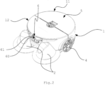
- Figur 2:
- Perspektivische Darstellung der in
Figur 1 - Figur 3:
- Unteransicht der in
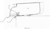
Figur 1 - Figur 4a:
- Seitenansicht der in
Figur 1 - Figur 4b:
- Schema einer Klappvorrichtung des Geräts bei Veränderung des Niveaus des Bodens,
- Figur 5:
- Seitenansicht der in
Figur 1 - Figur 6:
- Seitenansicht der in
Figur 1 - Figur 7:
- Seitenansicht der in
Figur 1 - Figur 8:
- Seitenansicht der in
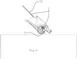
Figur 1 - Figur 9:
- Darstellung einer Abluftführung angeordnet an einem optischen Erkennungssystem.
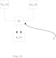
- Figur 10:
- Schematische Darstellung der Steuerung des Geräts.
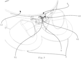
- Figur 11:
- Schematische Darstellung des Lokalisierungssystems des Geräts.
- Figure 1:
- Side view of a device in a first embodiment,
- Figure 2:
- Perspective view of the in
Figure 1 shown embodiment of the device, - Figure 3:
- Bottom view of the in
Figure 1 shown embodiment of the device, - Figure 4a:
- Side view of the in
Figure 1 shown embodiment of the device in operating position when the level of the ground changes, - Figure 4b:
- Diagram of a folding device of the device when the level of the ground changes,
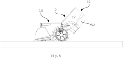
- Figure 5:
- Side view of the in
Figure 1 shown embodiment of the device in emptying position, - Figure 6:
- Side view of the in
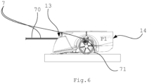
Figure 1 shown embodiment of the device in operating position with extended handle, - Figure 7:
- Side view of the in
Figure 1 shown embodiment of the device in operating position with extended handle and without dirt collection space, - Figure 8:
- Side view of the in
Figure 1 shown embodiment of the device in transport position with extended handle, - Figure 9:
- Representation of an exhaust air duct arranged on an optical detection system.
- Figure 10:
- Schematic representation of the control of the device.
- Figure 11:
- Schematic diagram of the device's localization system.
Ein in
Beispiele für die Position eines Bildes kann eine Ladestation 91 oder eine Schmutzaufnahmestation 55 zur Entleerung des Schmutzaufnahmeraums 51 sein (siehe
Eine Rechnereinheit 90 des Geräts kann (siehe
Die beiden Klappvorrichtungen 3 können unabhängig voneinander ausgelöst werden. Je nach dem, in welchem Winkel das Gerät 1 zur Veränderung des Niveaus des Bodens steht, können eine oder beide Klappvorrichtungen 3 nach unten geklappt sein.The two
Die
In
Eine Abdeckung des Schmutzaufnahmeraums oder der ganze Schmutzaufnahmeraum 51 kann mit Hilfe einer Haltevorrichtung (z.B. durch einen Rastmechanismus oder durch einen Magneten) an dem Griff 70 oder dem Gehäuse 10 (siehe
In
Durch die Abluftführung 8 geführte Luft wird durch eine Absaugvorrichtung 82 (siehe
Die Abluftführung 8 ist so angeordnet, dass Abluft 81 welche von der Absaugvorrichtung 82 erzeugt wird, zum optischen Erkennungssystem 6 in den vorderen Bereich 12 des Geräts 1 geleitet wird und über die Oberfläche der Linse 61 der Kamera 60 strömt (siehe Pfeile in
Claims (15)
dadurch gekennzeichnet, dass der Sensor (3) ein mechanischer Sensor ist und zur Feststellung einer Veränderung des Niveaus (N) des Bodens durch Kontakt mit dem Boden ausgebildet ist und im vorderen Bereich (12) angeordnet ist.Device (1) for automatically carrying out an activity, in particular for automatically cleaning dirty surfaces, in particular device according to one of claims 1 or 3 to 6, comprising at least one sensor (3) to prevent a fall and at least one drive element (4), wherein the Drive element (4) defines a rear area (11) and a front area (12) of the device (1), based on a intended direction of movement (B),
characterized in that the sensor (3) is a mechanical sensor and is designed to detect a change in the level (N) of the ground through contact with the ground and is arranged in the front area (12).
dadurch gekennzeichnet, dass der Sensor (3) in einen Träger eines Rads, insbesondere in eine Lenkrolle (32, 33) integriert ausgebildet ist.Device according to one of the preceding claims 11 or 12,
characterized in that the sensor (3) is integrated into a carrier of a wheel, in particular into a steering roller (32, 33).
dadurch gekennzeichnet, dass der Sensor (3) räumlich im Bereich von Bürsten angeordnet ist.Device according to one of the preceding claims 11 to 13,
characterized in that the sensor (3) is spatially arranged in the area of brushes.
dadurch gekennzeichnet, dass der Sensor (3) in klappbare Lenkrollen (32, 33) integriert ausgebildet ist.Device according to one of the preceding claims 13 or 14,
characterized in that the sensor (3) is integrated into foldable castors (32, 33).
Applications Claiming Priority (3)
| Application Number | Priority Date | Filing Date | Title |
|---|---|---|---|
| CH01542/18A CH715633A2 (en) | 2018-12-12 | 2018-12-12 | Device and method for automatically performing an activity, in particular for cleaning dirty surfaces. |
| EP19821063.5A EP3893710B1 (en) | 2018-12-12 | 2019-12-10 | Device for cleaning dirty surfaces |
| PCT/EP2019/084399 WO2020120462A2 (en) | 2018-12-12 | 2019-12-10 | Device and method for automatically performing an activity, in particular for cleaning dirty surfaces |
Related Parent Applications (1)
| Application Number | Title | Priority Date | Filing Date |
|---|---|---|---|
| EP19821063.5A Division EP3893710B1 (en) | 2018-12-12 | 2019-12-10 | Device for cleaning dirty surfaces |
Publications (1)
| Publication Number | Publication Date |
|---|---|
| EP4278940A2 true EP4278940A2 (en) | 2023-11-22 |
Family
ID=68887409
Family Applications (2)
| Application Number | Title | Priority Date | Filing Date |
|---|---|---|---|
| EP19821063.5A Active EP3893710B1 (en) | 2018-12-12 | 2019-12-10 | Device for cleaning dirty surfaces |
| EP23201753.3A Pending EP4278940A2 (en) | 2018-12-12 | 2019-12-10 | Device for cleaning dirty surfaces |
Family Applications Before (1)
| Application Number | Title | Priority Date | Filing Date |
|---|---|---|---|
| EP19821063.5A Active EP3893710B1 (en) | 2018-12-12 | 2019-12-10 | Device for cleaning dirty surfaces |
Country Status (11)
| Country | Link |
|---|---|
| US (1) | US20220022712A1 (en) |
| EP (2) | EP3893710B1 (en) |
| JP (1) | JP7458403B2 (en) |
| KR (1) | KR20210100151A (en) |
| CN (1) | CN113164001A (en) |
| AU (1) | AU2019398399A1 (en) |
| BR (1) | BR112021009598A2 (en) |
| CA (1) | CA3121049A1 (en) |
| CH (1) | CH715633A2 (en) |
| SG (1) | SG11202105317UA (en) |
| WO (1) | WO2020120462A2 (en) |
Families Citing this family (1)
| Publication number | Priority date | Publication date | Assignee | Title |
|---|---|---|---|---|
| WO2024055224A1 (en) | 2022-09-15 | 2024-03-21 | Sharkninja Operating Llc | Vacuum cleaner and docking station configured to cooperate with the same |
Citations (2)
| Publication number | Priority date | Publication date | Assignee | Title |
|---|---|---|---|---|
| US6580246B2 (en) | 2001-08-13 | 2003-06-17 | Steven Jacobs | Robot touch shield |
| DE102012108008A1 (en) | 2012-08-30 | 2014-03-06 | Miele & Cie. Kg | Self-propelled suction device for automated cleaning of surface, has sensor for detecting characteristics of environment of suction device, where sensor is arranged to detect liquid located on surface to be cleaned |
Family Cites Families (17)
| Publication number | Priority date | Publication date | Assignee | Title |
|---|---|---|---|---|
| AUPR154400A0 (en) * | 2000-11-17 | 2000-12-14 | Duplex Cleaning Machines Pty. Limited | Robot machine |
| CN2605152Y (en) * | 2002-12-25 | 2004-03-03 | 师峰 | Two-purpose tipping truck |
| CN2657571Y (en) * | 2003-09-27 | 2004-11-24 | 雷祖荫 | Electric ring-band cleaning apparatus |
| US7617557B2 (en) * | 2004-04-02 | 2009-11-17 | Royal Appliance Mfg. Co. | Powered cleaning appliance |
| US7620476B2 (en) * | 2005-02-18 | 2009-11-17 | Irobot Corporation | Autonomous surface cleaning robot for dry cleaning |
| KR100671897B1 (en) * | 2005-04-04 | 2007-01-24 | 주식회사 대우일렉트로닉스 | Robot vacuum cleaner having switch type sensor |
| KR101339513B1 (en) * | 2007-05-09 | 2013-12-10 | 아이로보트 코퍼레이션 | Autonomous coverage robot |
| DE102010016788B4 (en) * | 2010-05-05 | 2012-01-19 | Miele & Cie. Kg | Filter, vacuum cleaner with such a filter and use of such a filter as a vacuum cleaner exhaust filter |
| CN103356122A (en) * | 2012-04-05 | 2013-10-23 | 科沃斯机器人科技(苏州)有限公司 | Glass cleaning device |
| JP5803831B2 (en) * | 2012-07-23 | 2015-11-04 | 株式会社デンソー | In-vehicle optical sensor cleaning device |
| GB201301578D0 (en) * | 2013-01-29 | 2013-03-13 | Dyson Technology Ltd | Mobile robot |
| JP6207388B2 (en) * | 2013-12-27 | 2017-10-04 | シャープ株式会社 | Self-propelled vacuum cleaner |
| JP6634223B2 (en) | 2015-06-15 | 2020-01-22 | シャープ株式会社 | Self-propelled electronic device and traveling method of the self-propelled electronic device |
| JP6476077B2 (en) * | 2015-06-18 | 2019-02-27 | シャープ株式会社 | Self-propelled electronic device and traveling method of the self-propelled electronic device |
| CN105982624B (en) * | 2015-12-30 | 2019-04-16 | 小米科技有限责任公司 | Anti-jamming processing method and device for automatic cleaning equipment and automatic cleaning equipment |
| CN105962841A (en) * | 2016-06-22 | 2016-09-28 | 洛阳圣瑞智能机器人有限公司 | Glass wiping robot anti-falling device and method |
| CN106223765B (en) * | 2016-08-30 | 2018-03-13 | 北汽银翔汽车有限公司 | It is a kind of possess on turn over and under turn over the automobile back doors of opening ways |
-
2018
- 2018-12-12 CH CH01542/18A patent/CH715633A2/en unknown
-
2019
- 2019-12-10 WO PCT/EP2019/084399 patent/WO2020120462A2/en unknown
- 2019-12-10 KR KR1020217020946A patent/KR20210100151A/en active Search and Examination
- 2019-12-10 JP JP2021534295A patent/JP7458403B2/en active Active
- 2019-12-10 EP EP19821063.5A patent/EP3893710B1/en active Active
- 2019-12-10 US US17/311,736 patent/US20220022712A1/en active Pending
- 2019-12-10 BR BR112021009598-5A patent/BR112021009598A2/en unknown
- 2019-12-10 SG SG11202105317UA patent/SG11202105317UA/en unknown
- 2019-12-10 CN CN201980080959.1A patent/CN113164001A/en active Pending
- 2019-12-10 EP EP23201753.3A patent/EP4278940A2/en active Pending
- 2019-12-10 CA CA3121049A patent/CA3121049A1/en active Pending
- 2019-12-10 AU AU2019398399A patent/AU2019398399A1/en not_active Abandoned
Patent Citations (2)
| Publication number | Priority date | Publication date | Assignee | Title |
|---|---|---|---|---|
| US6580246B2 (en) | 2001-08-13 | 2003-06-17 | Steven Jacobs | Robot touch shield |
| DE102012108008A1 (en) | 2012-08-30 | 2014-03-06 | Miele & Cie. Kg | Self-propelled suction device for automated cleaning of surface, has sensor for detecting characteristics of environment of suction device, where sensor is arranged to detect liquid located on surface to be cleaned |
Also Published As
| Publication number | Publication date |
|---|---|
| EP3893710A2 (en) | 2021-10-20 |
| CN113164001A (en) | 2021-07-23 |
| EP3893710C0 (en) | 2023-10-18 |
| EP3893710B1 (en) | 2023-10-18 |
| AU2019398399A1 (en) | 2021-06-03 |
| KR20210100151A (en) | 2021-08-13 |
| JP2022513900A (en) | 2022-02-09 |
| WO2020120462A3 (en) | 2020-08-06 |
| BR112021009598A2 (en) | 2021-08-10 |
| SG11202105317UA (en) | 2021-07-29 |
| WO2020120462A2 (en) | 2020-06-18 |
| CA3121049A1 (en) | 2020-06-18 |
| US20220022712A1 (en) | 2022-01-27 |
| JP7458403B2 (en) | 2024-03-29 |
| CH715633A2 (en) | 2020-06-15 |
Similar Documents
| Publication | Publication Date | Title |
|---|---|---|
| EP3559769B1 (en) | Autonomous mobile robot and method for controlling an autonomous mobile robot | |
| DE102010000607B4 (en) | Household vacuum cleaner that can be used as a base station for an automatically movable suction and/or sweeping device | |
| DE102012108008A1 (en) | Self-propelled suction device for automated cleaning of surface, has sensor for detecting characteristics of environment of suction device, where sensor is arranged to detect liquid located on surface to be cleaned | |
| EP3379990B1 (en) | Floor cleaning system and method for cleaning a floor surface | |
| EP3409165B1 (en) | Support assembly to a robot cleaner | |
| DE102017113285A1 (en) | System with at least two cleaning devices | |
| DE102009041362A1 (en) | Method for operating a cleaning robot | |
| EP2764812A1 (en) | Cleaning robot | |
| DE102010017213A1 (en) | Method for emptying dirt collection container of automatically movable cleaning device, particularly robotic vacuum cleaner, involves carrying out emptying of dirt collection container through suction port | |
| EP3725202B1 (en) | Self-moving suction robot and system comprising an automatically moving suction robot and an external suction cleaner | |
| EP3409168B1 (en) | Corner cleaning module for modularly constructed cleaning robot | |
| DE102012105608A1 (en) | Self-propelled cleaning device and method for operating a self-propelled cleaning device | |
| DE102018116065A1 (en) | Method for operating a self-propelled service device | |
| DE102013219444A1 (en) | Charging device for inductive charging | |
| WO2019011648A1 (en) | Method for producing an electrical connection of a vehicle contact unit, vehicle connection device, and vehicle | |
| DE202009014405U1 (en) | Robotic vacuum cleaner with a sensor handle | |
| EP3893710B1 (en) | Device for cleaning dirty surfaces | |
| DE102014001482A1 (en) | Disposal vehicle with at least one feed device for receiving residues or the like | |
| DE102019129681A1 (en) | Dust collecting robot | |
| DE102018132964A1 (en) | AUTONOMOUS CLEANING DEVICE WITH A SUCTION ARM | |
| DE102018116225A1 (en) | cleaner | |
| DE102017126798A1 (en) | Self-propelled floor care device | |
| EP3428759A1 (en) | Method for operating an automatically moving service device | |
| BE1029365B1 (en) | Procedure for emptying cleaning robots and cleaning system | |
| DE102022207500B3 (en) | Method for operating a mobile, self-propelled device |
Legal Events
| Date | Code | Title | Description |
|---|---|---|---|
| PUAI | Public reference made under article 153(3) epc to a published international application that has entered the european phase |
Free format text: ORIGINAL CODE: 0009012 |
|
| STAA | Information on the status of an ep patent application or granted ep patent |
Free format text: STATUS: THE APPLICATION HAS BEEN PUBLISHED |
|
| AC | Divisional application: reference to earlier application |
Ref document number: 3893710 Country of ref document: EP Kind code of ref document: P |
|
| AK | Designated contracting states |
Kind code of ref document: A2 Designated state(s): AL AT BE BG CH CY CZ DE DK EE ES FI FR GB GR HR HU IE IS IT LI LT LU LV MC MK MT NL NO PL PT RO RS SE SI SK SM TR |
|
| RAP3 | Party data changed (applicant data changed or rights of an application transferred) |
Owner name: KEMARO AG |
|
| REG | Reference to a national code |
Ref country code: DE Ref legal event code: R079 Free format text: PREVIOUS MAIN CLASS: A47L0011300000 Ipc: A47L0011400000 |