EP3083158B1 - Optimal design of a lower limb exoskeleton or orthosis - Google Patents
Optimal design of a lower limb exoskeleton or orthosis Download PDFInfo
- Publication number
- EP3083158B1 EP3083158B1 EP14827333.7A EP14827333A EP3083158B1 EP 3083158 B1 EP3083158 B1 EP 3083158B1 EP 14827333 A EP14827333 A EP 14827333A EP 3083158 B1 EP3083158 B1 EP 3083158B1
- Authority
- EP
- European Patent Office
- Prior art keywords
- distal
- proximal
- module
- link
- crossing
- Prior art date
- Legal status (The legal status is an assumption and is not a legal conclusion. Google has not performed a legal analysis and makes no representation as to the accuracy of the status listed.)
- Active
Links
- 210000003141 lower extremity Anatomy 0.000 title claims description 25
- 238000013461 design Methods 0.000 title description 8
- 210000003423 ankle Anatomy 0.000 claims description 132
- 230000033001 locomotion Effects 0.000 claims description 59
- 210000003127 knee Anatomy 0.000 claims description 42
- 210000001624 hip Anatomy 0.000 claims description 35
- 210000002683 foot Anatomy 0.000 claims description 34
- 210000000629 knee joint Anatomy 0.000 claims description 32
- 210000000544 articulatio talocruralis Anatomy 0.000 claims description 30
- 210000000689 upper leg Anatomy 0.000 claims description 26
- 230000002457 bidirectional effect Effects 0.000 claims description 19
- 244000309466 calf Species 0.000 claims description 17
- 210000004394 hip joint Anatomy 0.000 claims description 12
- 210000002303 tibia Anatomy 0.000 claims description 12
- 101000911772 Homo sapiens Hsc70-interacting protein Proteins 0.000 claims description 9
- 210000002414 leg Anatomy 0.000 claims description 9
- 230000008878 coupling Effects 0.000 claims description 3
- 238000010168 coupling process Methods 0.000 claims description 3
- 238000005859 coupling reaction Methods 0.000 claims description 3
- 210000003414 extremity Anatomy 0.000 description 31
- 210000001699 lower leg Anatomy 0.000 description 26
- 230000007246 mechanism Effects 0.000 description 22
- 210000001503 joint Anatomy 0.000 description 18
- 230000005540 biological transmission Effects 0.000 description 12
- 230000005021 gait Effects 0.000 description 7
- 230000003137 locomotive effect Effects 0.000 description 7
- MHAJPDPJQMAIIY-UHFFFAOYSA-N Hydrogen peroxide Chemical compound OO MHAJPDPJQMAIIY-UHFFFAOYSA-N 0.000 description 6
- 238000009826 distribution Methods 0.000 description 6
- 230000003993 interaction Effects 0.000 description 5
- 239000004677 Nylon Substances 0.000 description 4
- 230000000694 effects Effects 0.000 description 4
- 229920001778 nylon Polymers 0.000 description 4
- 230000007170 pathology Effects 0.000 description 4
- 230000003044 adaptive effect Effects 0.000 description 3
- 238000006073 displacement reaction Methods 0.000 description 3
- 208000003947 Knee Osteoarthritis Diseases 0.000 description 2
- 208000018737 Parkinson disease Diseases 0.000 description 2
- ATUOYWHBWRKTHZ-UHFFFAOYSA-N Propane Chemical compound CCC ATUOYWHBWRKTHZ-UHFFFAOYSA-N 0.000 description 2
- 239000000853 adhesive Substances 0.000 description 2
- 230000001070 adhesive effect Effects 0.000 description 2
- 230000000386 athletic effect Effects 0.000 description 2
- -1 diesel Substances 0.000 description 2
- 230000004064 dysfunction Effects 0.000 description 2
- 230000004907 flux Effects 0.000 description 2
- 239000000446 fuel Substances 0.000 description 2
- 239000007788 liquid Substances 0.000 description 2
- 238000005259 measurement Methods 0.000 description 2
- 230000002503 metabolic effect Effects 0.000 description 2
- 238000000034 method Methods 0.000 description 2
- 230000004048 modification Effects 0.000 description 2
- 238000012986 modification Methods 0.000 description 2
- 201000008482 osteoarthritis Diseases 0.000 description 2
- 230000007704 transition Effects 0.000 description 2
- 238000013519 translation Methods 0.000 description 2
- 229920000049 Carbon (fiber) Polymers 0.000 description 1
- 238000005299 abrasion Methods 0.000 description 1
- XAGFODPZIPBFFR-UHFFFAOYSA-N aluminium Chemical compound [Al] XAGFODPZIPBFFR-UHFFFAOYSA-N 0.000 description 1
- 229910052782 aluminium Inorganic materials 0.000 description 1
- 230000003321 amplification Effects 0.000 description 1
- 238000004458 analytical method Methods 0.000 description 1
- 230000003416 augmentation Effects 0.000 description 1
- 230000003190 augmentative effect Effects 0.000 description 1
- 230000008901 benefit Effects 0.000 description 1
- 230000004071 biological effect Effects 0.000 description 1
- 239000004917 carbon fiber Substances 0.000 description 1
- 238000006243 chemical reaction Methods 0.000 description 1
- 239000002131 composite material Substances 0.000 description 1
- 230000006835 compression Effects 0.000 description 1
- 238000007906 compression Methods 0.000 description 1
- 238000009795 derivation Methods 0.000 description 1
- 238000001514 detection method Methods 0.000 description 1
- 229940079593 drug Drugs 0.000 description 1
- 239000003814 drug Substances 0.000 description 1
- 230000005672 electromagnetic field Effects 0.000 description 1
- 239000011152 fibreglass Substances 0.000 description 1
- 239000007789 gas Substances 0.000 description 1
- 210000003041 ligament Anatomy 0.000 description 1
- 239000000463 material Substances 0.000 description 1
- VNWKTOKETHGBQD-UHFFFAOYSA-N methane Chemical compound C VNWKTOKETHGBQD-UHFFFAOYSA-N 0.000 description 1
- 210000003205 muscle Anatomy 0.000 description 1
- 238000003199 nucleic acid amplification method Methods 0.000 description 1
- 230000003287 optical effect Effects 0.000 description 1
- 230000035479 physiological effects, processes and functions Effects 0.000 description 1
- 239000001294 propane Substances 0.000 description 1
- 230000035939 shock Effects 0.000 description 1
- 210000004872 soft tissue Anatomy 0.000 description 1
- 238000002560 therapeutic procedure Methods 0.000 description 1
Images


Classifications
-
- A—HUMAN NECESSITIES
- A61—MEDICAL OR VETERINARY SCIENCE; HYGIENE
- A61H—PHYSICAL THERAPY APPARATUS, e.g. DEVICES FOR LOCATING OR STIMULATING REFLEX POINTS IN THE BODY; ARTIFICIAL RESPIRATION; MASSAGE; BATHING DEVICES FOR SPECIAL THERAPEUTIC OR HYGIENIC PURPOSES OR SPECIFIC PARTS OF THE BODY
- A61H3/00—Appliances for aiding patients or disabled persons to walk about
-
- A—HUMAN NECESSITIES
- A61—MEDICAL OR VETERINARY SCIENCE; HYGIENE
- A61H—PHYSICAL THERAPY APPARATUS, e.g. DEVICES FOR LOCATING OR STIMULATING REFLEX POINTS IN THE BODY; ARTIFICIAL RESPIRATION; MASSAGE; BATHING DEVICES FOR SPECIAL THERAPEUTIC OR HYGIENIC PURPOSES OR SPECIFIC PARTS OF THE BODY
- A61H1/00—Apparatus for passive exercising; Vibrating apparatus ; Chiropractic devices, e.g. body impacting devices, external devices for briefly extending or aligning unbroken bones
- A61H1/02—Stretching or bending or torsioning apparatus for exercising
- A61H1/0237—Stretching or bending or torsioning apparatus for exercising for the lower limbs
-
- A—HUMAN NECESSITIES
- A61—MEDICAL OR VETERINARY SCIENCE; HYGIENE
- A61F—FILTERS IMPLANTABLE INTO BLOOD VESSELS; PROSTHESES; DEVICES PROVIDING PATENCY TO, OR PREVENTING COLLAPSING OF, TUBULAR STRUCTURES OF THE BODY, e.g. STENTS; ORTHOPAEDIC, NURSING OR CONTRACEPTIVE DEVICES; FOMENTATION; TREATMENT OR PROTECTION OF EYES OR EARS; BANDAGES, DRESSINGS OR ABSORBENT PADS; FIRST-AID KITS
- A61F2/00—Filters implantable into blood vessels; Prostheses, i.e. artificial substitutes or replacements for parts of the body; Appliances for connecting them with the body; Devices providing patency to, or preventing collapsing of, tubular structures of the body, e.g. stents
- A61F2/50—Prostheses not implantable in the body
- A61F2/60—Artificial legs or feet or parts thereof
- A61F2/605—Hip joints
-
- A—HUMAN NECESSITIES
- A61—MEDICAL OR VETERINARY SCIENCE; HYGIENE
- A61F—FILTERS IMPLANTABLE INTO BLOOD VESSELS; PROSTHESES; DEVICES PROVIDING PATENCY TO, OR PREVENTING COLLAPSING OF, TUBULAR STRUCTURES OF THE BODY, e.g. STENTS; ORTHOPAEDIC, NURSING OR CONTRACEPTIVE DEVICES; FOMENTATION; TREATMENT OR PROTECTION OF EYES OR EARS; BANDAGES, DRESSINGS OR ABSORBENT PADS; FIRST-AID KITS
- A61F2/00—Filters implantable into blood vessels; Prostheses, i.e. artificial substitutes or replacements for parts of the body; Appliances for connecting them with the body; Devices providing patency to, or preventing collapsing of, tubular structures of the body, e.g. stents
- A61F2/50—Prostheses not implantable in the body
- A61F2/60—Artificial legs or feet or parts thereof
- A61F2/64—Knee joints
-
- A—HUMAN NECESSITIES
- A61—MEDICAL OR VETERINARY SCIENCE; HYGIENE
- A61F—FILTERS IMPLANTABLE INTO BLOOD VESSELS; PROSTHESES; DEVICES PROVIDING PATENCY TO, OR PREVENTING COLLAPSING OF, TUBULAR STRUCTURES OF THE BODY, e.g. STENTS; ORTHOPAEDIC, NURSING OR CONTRACEPTIVE DEVICES; FOMENTATION; TREATMENT OR PROTECTION OF EYES OR EARS; BANDAGES, DRESSINGS OR ABSORBENT PADS; FIRST-AID KITS
- A61F2/00—Filters implantable into blood vessels; Prostheses, i.e. artificial substitutes or replacements for parts of the body; Appliances for connecting them with the body; Devices providing patency to, or preventing collapsing of, tubular structures of the body, e.g. stents
- A61F2/50—Prostheses not implantable in the body
- A61F2/60—Artificial legs or feet or parts thereof
- A61F2/66—Feet; Ankle joints
- A61F2/6607—Ankle joints
-
- A—HUMAN NECESSITIES
- A61—MEDICAL OR VETERINARY SCIENCE; HYGIENE
- A61F—FILTERS IMPLANTABLE INTO BLOOD VESSELS; PROSTHESES; DEVICES PROVIDING PATENCY TO, OR PREVENTING COLLAPSING OF, TUBULAR STRUCTURES OF THE BODY, e.g. STENTS; ORTHOPAEDIC, NURSING OR CONTRACEPTIVE DEVICES; FOMENTATION; TREATMENT OR PROTECTION OF EYES OR EARS; BANDAGES, DRESSINGS OR ABSORBENT PADS; FIRST-AID KITS
- A61F5/00—Orthopaedic methods or devices for non-surgical treatment of bones or joints; Nursing devices; Anti-rape devices
- A61F5/01—Orthopaedic devices, e.g. splints, casts or braces
- A61F5/0102—Orthopaedic devices, e.g. splints, casts or braces specially adapted for correcting deformities of the limbs or for supporting them; Ortheses, e.g. with articulations
-
- A—HUMAN NECESSITIES
- A61—MEDICAL OR VETERINARY SCIENCE; HYGIENE
- A61H—PHYSICAL THERAPY APPARATUS, e.g. DEVICES FOR LOCATING OR STIMULATING REFLEX POINTS IN THE BODY; ARTIFICIAL RESPIRATION; MASSAGE; BATHING DEVICES FOR SPECIAL THERAPEUTIC OR HYGIENIC PURPOSES OR SPECIFIC PARTS OF THE BODY
- A61H1/00—Apparatus for passive exercising; Vibrating apparatus ; Chiropractic devices, e.g. body impacting devices, external devices for briefly extending or aligning unbroken bones
- A61H1/02—Stretching or bending or torsioning apparatus for exercising
- A61H1/0237—Stretching or bending or torsioning apparatus for exercising for the lower limbs
- A61H1/024—Knee
-
- A—HUMAN NECESSITIES
- A61—MEDICAL OR VETERINARY SCIENCE; HYGIENE
- A61H—PHYSICAL THERAPY APPARATUS, e.g. DEVICES FOR LOCATING OR STIMULATING REFLEX POINTS IN THE BODY; ARTIFICIAL RESPIRATION; MASSAGE; BATHING DEVICES FOR SPECIAL THERAPEUTIC OR HYGIENIC PURPOSES OR SPECIFIC PARTS OF THE BODY
- A61H1/00—Apparatus for passive exercising; Vibrating apparatus ; Chiropractic devices, e.g. body impacting devices, external devices for briefly extending or aligning unbroken bones
- A61H1/02—Stretching or bending or torsioning apparatus for exercising
- A61H1/0237—Stretching or bending or torsioning apparatus for exercising for the lower limbs
- A61H1/0244—Hip
-
- A—HUMAN NECESSITIES
- A61—MEDICAL OR VETERINARY SCIENCE; HYGIENE
- A61H—PHYSICAL THERAPY APPARATUS, e.g. DEVICES FOR LOCATING OR STIMULATING REFLEX POINTS IN THE BODY; ARTIFICIAL RESPIRATION; MASSAGE; BATHING DEVICES FOR SPECIAL THERAPEUTIC OR HYGIENIC PURPOSES OR SPECIFIC PARTS OF THE BODY
- A61H1/00—Apparatus for passive exercising; Vibrating apparatus ; Chiropractic devices, e.g. body impacting devices, external devices for briefly extending or aligning unbroken bones
- A61H1/02—Stretching or bending or torsioning apparatus for exercising
- A61H1/0237—Stretching or bending or torsioning apparatus for exercising for the lower limbs
- A61H1/0266—Foot
-
- B—PERFORMING OPERATIONS; TRANSPORTING
- B25—HAND TOOLS; PORTABLE POWER-DRIVEN TOOLS; MANIPULATORS
- B25J—MANIPULATORS; CHAMBERS PROVIDED WITH MANIPULATION DEVICES
- B25J9/00—Programme-controlled manipulators
- B25J9/0006—Exoskeletons, i.e. resembling a human figure
-
- A—HUMAN NECESSITIES
- A61—MEDICAL OR VETERINARY SCIENCE; HYGIENE
- A61F—FILTERS IMPLANTABLE INTO BLOOD VESSELS; PROSTHESES; DEVICES PROVIDING PATENCY TO, OR PREVENTING COLLAPSING OF, TUBULAR STRUCTURES OF THE BODY, e.g. STENTS; ORTHOPAEDIC, NURSING OR CONTRACEPTIVE DEVICES; FOMENTATION; TREATMENT OR PROTECTION OF EYES OR EARS; BANDAGES, DRESSINGS OR ABSORBENT PADS; FIRST-AID KITS
- A61F5/00—Orthopaedic methods or devices for non-surgical treatment of bones or joints; Nursing devices; Anti-rape devices
- A61F5/01—Orthopaedic devices, e.g. splints, casts or braces
- A61F5/0102—Orthopaedic devices, e.g. splints, casts or braces specially adapted for correcting deformities of the limbs or for supporting them; Ortheses, e.g. with articulations
- A61F2005/0132—Additional features of the articulation
- A61F2005/0155—Additional features of the articulation with actuating means
-
- A—HUMAN NECESSITIES
- A61—MEDICAL OR VETERINARY SCIENCE; HYGIENE
- A61F—FILTERS IMPLANTABLE INTO BLOOD VESSELS; PROSTHESES; DEVICES PROVIDING PATENCY TO, OR PREVENTING COLLAPSING OF, TUBULAR STRUCTURES OF THE BODY, e.g. STENTS; ORTHOPAEDIC, NURSING OR CONTRACEPTIVE DEVICES; FOMENTATION; TREATMENT OR PROTECTION OF EYES OR EARS; BANDAGES, DRESSINGS OR ABSORBENT PADS; FIRST-AID KITS
- A61F5/00—Orthopaedic methods or devices for non-surgical treatment of bones or joints; Nursing devices; Anti-rape devices
- A61F5/01—Orthopaedic devices, e.g. splints, casts or braces
- A61F5/0102—Orthopaedic devices, e.g. splints, casts or braces specially adapted for correcting deformities of the limbs or for supporting them; Ortheses, e.g. with articulations
- A61F2005/0132—Additional features of the articulation
- A61F2005/0179—Additional features of the articulation with spring means
-
- A—HUMAN NECESSITIES
- A61—MEDICAL OR VETERINARY SCIENCE; HYGIENE
- A61H—PHYSICAL THERAPY APPARATUS, e.g. DEVICES FOR LOCATING OR STIMULATING REFLEX POINTS IN THE BODY; ARTIFICIAL RESPIRATION; MASSAGE; BATHING DEVICES FOR SPECIAL THERAPEUTIC OR HYGIENIC PURPOSES OR SPECIFIC PARTS OF THE BODY
- A61H2201/00—Characteristics of apparatus not provided for in the preceding codes
- A61H2201/12—Driving means
- A61H2201/1207—Driving means with electric or magnetic drive
- A61H2201/1215—Rotary drive
-
- A—HUMAN NECESSITIES
- A61—MEDICAL OR VETERINARY SCIENCE; HYGIENE
- A61H—PHYSICAL THERAPY APPARATUS, e.g. DEVICES FOR LOCATING OR STIMULATING REFLEX POINTS IN THE BODY; ARTIFICIAL RESPIRATION; MASSAGE; BATHING DEVICES FOR SPECIAL THERAPEUTIC OR HYGIENIC PURPOSES OR SPECIFIC PARTS OF THE BODY
- A61H2201/00—Characteristics of apparatus not provided for in the preceding codes
- A61H2201/12—Driving means
- A61H2201/1238—Driving means with hydraulic or pneumatic drive
-
- A—HUMAN NECESSITIES
- A61—MEDICAL OR VETERINARY SCIENCE; HYGIENE
- A61H—PHYSICAL THERAPY APPARATUS, e.g. DEVICES FOR LOCATING OR STIMULATING REFLEX POINTS IN THE BODY; ARTIFICIAL RESPIRATION; MASSAGE; BATHING DEVICES FOR SPECIAL THERAPEUTIC OR HYGIENIC PURPOSES OR SPECIFIC PARTS OF THE BODY
- A61H2201/00—Characteristics of apparatus not provided for in the preceding codes
- A61H2201/12—Driving means
- A61H2201/1253—Driving means driven by a human being, e.g. hand driven
- A61H2201/1261—Driving means driven by a human being, e.g. hand driven combined with active exercising of the patient
-
- A—HUMAN NECESSITIES
- A61—MEDICAL OR VETERINARY SCIENCE; HYGIENE
- A61H—PHYSICAL THERAPY APPARATUS, e.g. DEVICES FOR LOCATING OR STIMULATING REFLEX POINTS IN THE BODY; ARTIFICIAL RESPIRATION; MASSAGE; BATHING DEVICES FOR SPECIAL THERAPEUTIC OR HYGIENIC PURPOSES OR SPECIFIC PARTS OF THE BODY
- A61H2201/00—Characteristics of apparatus not provided for in the preceding codes
- A61H2201/14—Special force transmission means, i.e. between the driving means and the interface with the user
- A61H2201/1409—Hydraulic or pneumatic means
-
- A—HUMAN NECESSITIES
- A61—MEDICAL OR VETERINARY SCIENCE; HYGIENE
- A61H—PHYSICAL THERAPY APPARATUS, e.g. DEVICES FOR LOCATING OR STIMULATING REFLEX POINTS IN THE BODY; ARTIFICIAL RESPIRATION; MASSAGE; BATHING DEVICES FOR SPECIAL THERAPEUTIC OR HYGIENIC PURPOSES OR SPECIFIC PARTS OF THE BODY
- A61H2201/00—Characteristics of apparatus not provided for in the preceding codes
- A61H2201/14—Special force transmission means, i.e. between the driving means and the interface with the user
- A61H2201/1436—Special crank assembly
-
- A—HUMAN NECESSITIES
- A61—MEDICAL OR VETERINARY SCIENCE; HYGIENE
- A61H—PHYSICAL THERAPY APPARATUS, e.g. DEVICES FOR LOCATING OR STIMULATING REFLEX POINTS IN THE BODY; ARTIFICIAL RESPIRATION; MASSAGE; BATHING DEVICES FOR SPECIAL THERAPEUTIC OR HYGIENIC PURPOSES OR SPECIFIC PARTS OF THE BODY
- A61H2201/00—Characteristics of apparatus not provided for in the preceding codes
- A61H2201/14—Special force transmission means, i.e. between the driving means and the interface with the user
- A61H2201/1481—Special movement conversion means
- A61H2201/149—Special movement conversion means rotation-linear or vice versa
-
- A—HUMAN NECESSITIES
- A61—MEDICAL OR VETERINARY SCIENCE; HYGIENE
- A61H—PHYSICAL THERAPY APPARATUS, e.g. DEVICES FOR LOCATING OR STIMULATING REFLEX POINTS IN THE BODY; ARTIFICIAL RESPIRATION; MASSAGE; BATHING DEVICES FOR SPECIAL THERAPEUTIC OR HYGIENIC PURPOSES OR SPECIFIC PARTS OF THE BODY
- A61H2201/00—Characteristics of apparatus not provided for in the preceding codes
- A61H2201/16—Physical interface with patient
- A61H2201/1602—Physical interface with patient kind of interface, e.g. head rest, knee support or lumbar support
- A61H2201/1628—Pelvis
-
- A—HUMAN NECESSITIES
- A61—MEDICAL OR VETERINARY SCIENCE; HYGIENE
- A61H—PHYSICAL THERAPY APPARATUS, e.g. DEVICES FOR LOCATING OR STIMULATING REFLEX POINTS IN THE BODY; ARTIFICIAL RESPIRATION; MASSAGE; BATHING DEVICES FOR SPECIAL THERAPEUTIC OR HYGIENIC PURPOSES OR SPECIFIC PARTS OF THE BODY
- A61H2201/00—Characteristics of apparatus not provided for in the preceding codes
- A61H2201/16—Physical interface with patient
- A61H2201/1602—Physical interface with patient kind of interface, e.g. head rest, knee support or lumbar support
- A61H2201/164—Feet or leg, e.g. pedal
-
- A—HUMAN NECESSITIES
- A61—MEDICAL OR VETERINARY SCIENCE; HYGIENE
- A61H—PHYSICAL THERAPY APPARATUS, e.g. DEVICES FOR LOCATING OR STIMULATING REFLEX POINTS IN THE BODY; ARTIFICIAL RESPIRATION; MASSAGE; BATHING DEVICES FOR SPECIAL THERAPEUTIC OR HYGIENIC PURPOSES OR SPECIFIC PARTS OF THE BODY
- A61H2201/00—Characteristics of apparatus not provided for in the preceding codes
- A61H2201/16—Physical interface with patient
- A61H2201/1602—Physical interface with patient kind of interface, e.g. head rest, knee support or lumbar support
- A61H2201/165—Wearable interfaces
-
- A—HUMAN NECESSITIES
- A61—MEDICAL OR VETERINARY SCIENCE; HYGIENE
- A61H—PHYSICAL THERAPY APPARATUS, e.g. DEVICES FOR LOCATING OR STIMULATING REFLEX POINTS IN THE BODY; ARTIFICIAL RESPIRATION; MASSAGE; BATHING DEVICES FOR SPECIAL THERAPEUTIC OR HYGIENIC PURPOSES OR SPECIFIC PARTS OF THE BODY
- A61H2201/00—Characteristics of apparatus not provided for in the preceding codes
- A61H2201/16—Physical interface with patient
- A61H2201/1657—Movement of interface, i.e. force application means
- A61H2201/1676—Pivoting
-
- A—HUMAN NECESSITIES
- A61—MEDICAL OR VETERINARY SCIENCE; HYGIENE
- A61H—PHYSICAL THERAPY APPARATUS, e.g. DEVICES FOR LOCATING OR STIMULATING REFLEX POINTS IN THE BODY; ARTIFICIAL RESPIRATION; MASSAGE; BATHING DEVICES FOR SPECIAL THERAPEUTIC OR HYGIENIC PURPOSES OR SPECIFIC PARTS OF THE BODY
- A61H2201/00—Characteristics of apparatus not provided for in the preceding codes
- A61H2201/50—Control means thereof
- A61H2201/5007—Control means thereof computer controlled
-
- A—HUMAN NECESSITIES
- A61—MEDICAL OR VETERINARY SCIENCE; HYGIENE
- A61H—PHYSICAL THERAPY APPARATUS, e.g. DEVICES FOR LOCATING OR STIMULATING REFLEX POINTS IN THE BODY; ARTIFICIAL RESPIRATION; MASSAGE; BATHING DEVICES FOR SPECIAL THERAPEUTIC OR HYGIENIC PURPOSES OR SPECIFIC PARTS OF THE BODY
- A61H2201/00—Characteristics of apparatus not provided for in the preceding codes
- A61H2201/50—Control means thereof
- A61H2201/5058—Sensors or detectors
- A61H2201/5061—Force sensors
-
- A—HUMAN NECESSITIES
- A61—MEDICAL OR VETERINARY SCIENCE; HYGIENE
- A61H—PHYSICAL THERAPY APPARATUS, e.g. DEVICES FOR LOCATING OR STIMULATING REFLEX POINTS IN THE BODY; ARTIFICIAL RESPIRATION; MASSAGE; BATHING DEVICES FOR SPECIAL THERAPEUTIC OR HYGIENIC PURPOSES OR SPECIFIC PARTS OF THE BODY
- A61H2201/00—Characteristics of apparatus not provided for in the preceding codes
- A61H2201/50—Control means thereof
- A61H2201/5058—Sensors or detectors
- A61H2201/5069—Angle sensors
-
- A—HUMAN NECESSITIES
- A61—MEDICAL OR VETERINARY SCIENCE; HYGIENE
- A61H—PHYSICAL THERAPY APPARATUS, e.g. DEVICES FOR LOCATING OR STIMULATING REFLEX POINTS IN THE BODY; ARTIFICIAL RESPIRATION; MASSAGE; BATHING DEVICES FOR SPECIAL THERAPEUTIC OR HYGIENIC PURPOSES OR SPECIFIC PARTS OF THE BODY
- A61H2201/00—Characteristics of apparatus not provided for in the preceding codes
- A61H2201/50—Control means thereof
- A61H2201/5058—Sensors or detectors
- A61H2201/5071—Pressure sensors
-
- A—HUMAN NECESSITIES
- A61—MEDICAL OR VETERINARY SCIENCE; HYGIENE
- A61H—PHYSICAL THERAPY APPARATUS, e.g. DEVICES FOR LOCATING OR STIMULATING REFLEX POINTS IN THE BODY; ARTIFICIAL RESPIRATION; MASSAGE; BATHING DEVICES FOR SPECIAL THERAPEUTIC OR HYGIENIC PURPOSES OR SPECIFIC PARTS OF THE BODY
- A61H2201/00—Characteristics of apparatus not provided for in the preceding codes
- A61H2201/50—Control means thereof
- A61H2201/5058—Sensors or detectors
- A61H2201/5082—Temperature sensors
-
- A—HUMAN NECESSITIES
- A61—MEDICAL OR VETERINARY SCIENCE; HYGIENE
- A61H—PHYSICAL THERAPY APPARATUS, e.g. DEVICES FOR LOCATING OR STIMULATING REFLEX POINTS IN THE BODY; ARTIFICIAL RESPIRATION; MASSAGE; BATHING DEVICES FOR SPECIAL THERAPEUTIC OR HYGIENIC PURPOSES OR SPECIFIC PARTS OF THE BODY
- A61H2201/00—Characteristics of apparatus not provided for in the preceding codes
- A61H2201/50—Control means thereof
- A61H2201/5058—Sensors or detectors
- A61H2201/5084—Acceleration sensors
-
- A—HUMAN NECESSITIES
- A61—MEDICAL OR VETERINARY SCIENCE; HYGIENE
- A61H—PHYSICAL THERAPY APPARATUS, e.g. DEVICES FOR LOCATING OR STIMULATING REFLEX POINTS IN THE BODY; ARTIFICIAL RESPIRATION; MASSAGE; BATHING DEVICES FOR SPECIAL THERAPEUTIC OR HYGIENIC PURPOSES OR SPECIFIC PARTS OF THE BODY
- A61H2230/00—Measuring physical parameters of the user
- A61H2230/60—Muscle strain, i.e. measured on the user, e.g. Electromyography [EMG]
- A61H2230/605—Muscle strain, i.e. measured on the user, e.g. Electromyography [EMG] used as a control parameter for the apparatus
Definitions
- Exoskeletons, orthoses and prostheses are intended to enhance human function, often in the context of locomotory motion.
- Exoskeletons for example, are worn on the body exterior, around a biological joint that is the target of an intended function (e.g., knee or hip).
- the mechanical effect of the exoskeleton may be to add, remove or store and release energy. Irrespective of purpose, however, all exchange of energy between a human user and a worn exoskeleton occurs through mechanical interaction between the exoskeleton and the human body. The mechanical interaction imparts force distributions on the soft tissue surrounding the joint and limb segments.
- the exoskeleton uses a mechanical joint in parallel with the anatomical joint, which reduces flexibility, or the force distributions are parallel to the axis of the limb (i.e. shear), which may be uncomfortable to the user. This discomfort often disrupts device function and hinders the efficacy of the exoskeleton.
- limb joints are usually considered as one-to-three degrees of freedom (DOF) joints of multiple single DOF hinge joints in a single plane.
- DOF degrees of freedom
- biological joints are complex and usually rotate with respect to a changing instantaneous center.
- knee motion may be visualized as rotation of a femur about a series of three-dimensional instantaneous axes rather than a single fixed axis.
- a mismatch between limb joint motion and mechanical interface motion typically leads to undesired ligament and muscle length changes and other internal mechanical changes. Those undesired effects contribute to discomfort, as well as to slippage and sluggish interaction with such devices.
- the patent application WO 2009/149206 discloses a therapeutic method and device for rehabilitation whereby a subject-controllable range of joint motion is extended, and subject control of joint movement within a range of motion is increased. However slippage of the wearable device on the user's body still need to be avoided.
- the invention is generally directed to a wearable device, such as a prosthesis, orthosis or exoskeleton, such as for use with the human biological ankle, knee or hip, or a lower limb of any combination of the human ankle, knee and hip.
- the device includes a distal member wearable by an individual distal to a skeletal joint of the individual, a proximal member wearable by the individual proximal to the joint and a link between the distal and proximal member.
- One or the other of the distal member and the proximal member includes a crossing member, wherein the link extends from the crossing member of the distal member or the proximal member to the other of the distal member or the proximal member. Actuation of the link translates to a force at the distal or proximal member that is normal to a major longitudinal axis extending through the distal and proximal members when worn by the human individual.
- the crossing member is rigid.
- the crossing member can be rigidly or not rigidly fixed to one or the other of the distal member and the proximal member.
- the link includes a ball screw actuator.
- the link and the crossing member are components of a series elastic actuator.
- the series elastic actuator can be, for example, a bidirectional actuator, such as a pneumatic actuator.
- An example of a suitable pneumatic actuator for use with the present invention includes a hardening series elastic element.
- the pneumatic actuator includes an inflatable bladder.
- the series elastic actuator is a unidirectional actuator, such as a pneumatic actuator or an electric spool actuator.
- the crossing member can include the distal end and proximal end, wherein the distal end is fixed to the distal member at one end and is essentially normal to a major longitudinal axis of the distal member, and wherein the link extends between the proximal end of the crossing member and the proximal member.
- the distal member includes a surface that is essentially parallel to a plane that is normal to the major longitudinal axis extending between the distal and proximal members.
- the device of the invention further includes a second crossing member extending from the distal member, wherein the crossing members are essentially parallel to each other.
- the distal member is configured to support and to be secured to a human foot
- the crossing members are configured to extend essentially dorsally and parallel to a tibia extending from the human foot
- the proximal member is secured to a calf of the human
- an electric spool actuator includes a cable that is linked to the proximal end of the crossing member and spans the calf normally to a major longitudinal axis of the human tibia, whereby actuation of the actuator causes rotation of the distal member about human ankle joint to thereby at least assist plantar flexion of the human foot while walking.
- the crossing member is not rigid.
- the link includes a strut extending from the proximal member to the distal member, whereby the crossing member and the strut span the axis about which the distal member rotates.
- the strut is constrained at the proximal member normally and laterally to a major longitudinal axis of the crossing member extending from the proximal number to the distal member, wherein the strut is not restricted along the major longitudinal axis of the crossing member.
- the link further includes at least one roller at the proximal member that constrains the strut normally and laterally.
- the link includes at least one pair of rollers in opposition to each other, wherein the strut is normally constrained between the pair of rollers.
- the strut can be curved at the pair of rollers, whereby shear force between the strut and pair of rollers during rotation of the distal member of the axis spanned by the crossing member and the strut is less than it would be if the strut were straight at the pair of rollers.
- the strut includes a guide tube at the pair of rollers, wherein the crossing member extends through the guide tube.
- the device includes a pair of crossing members and a pair of struts.
- the struts are essentially straight between the rollers and the distal member.
- At least one of the struts deflects during eversion and inversion of the human foot secured to the distal member and a human calf secured to the proximal member.
- the struts are rigid.
- the struts are curved, whereby the struts operate as series springs during a normal walking cycle of human foot secured to the distal member and the human calf secured to the proximal member.
- the link further includes a winch actuator assembly attached to a proximal end of the pair of crossing members, whereby actuation of the link will cause retraction of the crossing members, which causes rotation of the distal member and plantar flexion of the human foot secured to the distal member about a human ankle joint.
- the pair of crossing members is fixed to a proximal end of the distal member.
- a second pair of crossing members can be fixed to a distal end of the distant member.
- the link further includes a second winch actuator assembly attached to a proximal end of the second pair of crossing members, whereby selective actuation of the link causes retraction of the second pair of crossing members, which causes rotation of the distal member and dorsiflexion of the human foot secured to the distal member about the human ankle joint.
- the distal members are configured to fit the human calf.
- the proximal member can be configured to fit the human thigh.
- the crossing member extends proximally from the distal member, and the link extends between the proximal member and a proximal end of the crossing member, whereby actuation of the link will cause extension of a human leg secured to the proximal and distal members.
- the crossing member extends distally from the proximal member and the link extends between a distal end of the crossing member and the distal member, whereby actuation of a link will cause extension of the human leg secured to the proximal and distal members.
- the proximal member is configured to fit a human waist.
- the distal member is configured to fit a human thigh.
- the crossing member extends proximally from the distal member.
- the link includes a bidirectional actuator, whereby actuation of the link will rotate the distal member and a human thigh secured to the distal member about a hip joint of a human wearing the device.
- the bidirectional actuator is a ball screw actuator.
- a wearable lower limb device that includes a distal module wearable by an individual that spans a distal skeletal joint and a proximal module wearable by the individual that spans a proximal skeletal joint, wherein the distal module and the proximal module are coupled.
- At least one of the distal and proximal modules includes a distal member wearable by the individual distal to the respective skeletal joint, a proximal member wearable by the individual proximal to the respective skeletal joint, and a link between the distal and proximal members, whereby actuation of the link will be translated to a force at the distal or proximal member that is normal to a major longitudinal axis extending through the distal and proximal members.
- at least one of the other of the distal member and proximal member includes a crossing member, and the link extends from the crossing member of the distal member or the proximal member to the other of the distal member or the proximal member.
- both the distal module and the proximal module include a distal member, a proximal member, a crossing member and a link.
- the distal module and the proximal module can be coupled by a common member, wherein the proximal member of the distal module is also at least a component of the distal member of the proximal module.
- the distal module and the proximal module can be rigidly coupled.
- the common member includes a degree of freedom coupling the distal module to the proximal module.
- the degree of freedom can be a hinge causing rotation in a plane essentially parallel to a plane of rotation of at least one of the proximal module and distal module.
- the distal module can be, for example, an exoskeleton, orthosis or prosthesis configured for use with a human knee joint, while the proximal module can be an exoskeleton, orthosis or prosthesis configured for use with a human hip joint.
- the link of the distal and proximal modules can each include a winch actuator or a ball screw actuator.
- the crossing member of the distal module includes a pulley and a cord linking the pulley, and a link of the distal module includes a winch actuator, whereby actuation of the link of the distal module causes extension of the human knee secured to the distal module.
- the distal member of the distal module can include, for example, a leaf spring linking the pulley to the distal member of the display module.
- the crossing member of the distal module extends proximally from the hinge of the distal member of the proximal module.
- the link of the proximal module can include a cord and a winch actuator that is at the proximal member of the proximal module, wherein the cord extends from the crossing member of the proximal module to the winch actuator, whereby actuation of the link of the proximal module will cause flexion movement of a human hip secured to the proximal module.
- the link of the proximal module includes a ball screw actuator, whereby actuation of the link is bidirectional and, selectively causes flexion and extension of a human hip secured to the proximal member.
- the lower limb device further includes an ankle module that is distal to the distal module, wherein the ankle module is coupled to the distal module, and wherein the distal module and the ankle module share a common member.
- the ankle module includes an ankle distal member, an ankle proximal member, and an ankle link between the ankle distal number and the ankle proximal member, whereby actuation of the ankle link will be translated to a force at the ankle distal member or the ankle proximal member that is normal to a major longitudinal axis extending through the ankle distal end ankle proximal members.
- At least one or the other of the ankle distal and the ankle proximal member includes an ankle crossing member, wherein the ankle link extends from the ankle crossing member of the ankle distal member or the ankle proximal member to the other of the ankle distal member or the ankle proximal member.
- the crossing member of the ankle module extends proximally from the distal member of the ankle module.
- the link of the ankle module includes a winch actuator at the proximal member of the ankle module, wherein a cord of the winch actuator extends from a proximal end of the crossing member to the winch actuator of the ankle module, whereby actuation of the link causes plantar flexion of a human ankle secured to the ankle module.
- the wearable lower limb device of the invention can be, for example, an exoskeleton, orthosis or prosthesis for a human ankle, and the proximal module can be an exoskeleton, orthosis or prosthesis for a human knee.
- the wearable device includes a link that applies a substantially linear force to the crossing member.
- the device of the invention includes a ground link that is fixed relative to either a distal end of a human femur or a proximal end of a human tibia.
- An input link having a first end and a second end is fixed to and rotates about a pivot defining an axis of rotation, wherein the pivot links the input link at the first end to the ground link.
- a coupler having a first end and a second end is pivotally mounted to the second end of the input link.
- An output link is fixed relative to the other of the distal end of the human femur or the proximal end of the human tibia and has a first end and a second end, the first end being pivotally mounted at the first end to the second end of the coupler.
- a sliding link is located between the ground link and the output link, whereby rotation of the human knee joint to which the device is secured will cause translation of an axis of rotation of the output link relative to the ground link to track two degrees of freedom of the human knee joint, wherein the human knee joint rotates in a sagittal plane about an axis that is normal to the sagittal plane but which moves relative to the axis of rotation of the pivot linking the first end of the input link to the ground link.
- the sliding link includes a slot defined by the output link, wherein a protrusion from the ground link extends through the slot defined by the sliding link, the sliding link restricting movement of the axis of rotation of the output link to a line normal to an axis of rotation of the pivot.
- One purpose of this invention is to modify the force distributions of an exoskeleton, orthosis or prosthesis on a limb.
- the intent is to alter the forces such that they are no longer parallel to the axis of the limb, but instead, perpendicular to the axis, whereby loading will be substantially more comfortable.
- Another purpose of this invention is to transmit planetary torques from either active or passive devices to limbs without altering the normal biological joint motions.
- the intent is to apply torques to a limb by utilizing an unconstrained multiple DOF mechanism, thereby providing an adaptive trajectory of instantaneous centers of the device matching that of the biological joints.
- the device of the present invention employs a geometric configuration that does not require artificial joints, therefore, making the device more comfortable and lighter.
- the comfort and weight of the device of the invention plays a large role in its ability to augment or rehabilitate the physical capabilities of an individual wearing the device.
- the device of the invention can constrain the linkage system and set trajectories of instantaneous centers of the device in accordance with normal biological joint motions while the external sources apply torques to the joint at the same time.
- mismatch between limb joint motion and mechanical interface motion is largely avoided, as well as skin shear force, undesired slippage and sluggish interaction between the individual and the device.
- the device of the invention can also act in the sagittal plane so that external sources can apply torques to joints of the individual without impeding rotation of the joint in the other planes, i.e., coronal or transverse.
- external sources can apply torques to joints of the individual without impeding rotation of the joint in the other planes, i.e., coronal or transverse.
- a force balance transmission is maintained in the sagittal plane of the individual so that external sources can apply torques to the biological joint in the sagittal plane without impeding rotation of the biological joint in the other two planes.
- the device of the invention also avoids significant skin shear force at the mechanical interface with the individual wearer. As a result, mismatch between ankle joint motion, for example, and mechanical interface motion is substantially avoided, as well as undesired large additional inertia added by the device of the invention.
- Enhancement may center on modification of ambulation of able-bodied persons or individuals with movement pathology.
- the invention can enhance locomotory function beyond what is otherwise physiologically possible.
- physical enhancement could be employed to assist professional duties (such as military or civil service duties), athletic achievement, recreation, or other opportunities.
- gait dysfunction resulting from movement pathology such as Parkinson's disease or knee osteoarthritis, or restoration of age-related reduced locomotory function could be treated or relieved by this invention.
- the invention is directed to an assistive or augmenting device that physically interacts with a person.
- One part of the invention is directed to a lower limb joint exoskeleton that physically interfaces with a person.
- a second part of the invention is directed to a joint exoskeleton or assistive device that physically interfaces with a person without having a significant mismatch between limb joint motion and mechanical interface motion in the same plane.
- a third part of the invention is directed to an ankle joint exoskeleton or assistive device that interfaces with a person without adding significant additional leg inertia to the human body or impeding ankle joint motion.
- a fourth part of the invention is directed to a device that enables external-internal rotation and inversion-eversion rotation while applying a torque in the sagittal plane, so that an attached biological ankle joint can maintain the normal gait.
- a fifth part of the invention is directed to a device that augments a hip, knee and ankle while minimizing shear on skin.
- the invention is directed to a wearable device, such as a lower limb exoskeleton that mechanically interacts with human joints of a lower extremity while maintaining joint flexibility and reducing shear on skin.
- the device of the invention does not have a mechanical joint in parallel with the anatomical joint. Rather, it has at least one component distally attached to the human body with respect to the anatomical joint and at least one component proximally attached to the body with respect to the anatomical joint.
- An actuator exerts a force between these components in order to reduce reactive shear stress on the skin. In other words, the forces are generally applied in a normal direction (i.e. perpendicular) to the body's surface.
- one or the other of the distal member and the proximal member includes a crossing member, wherein the link extends from the crossing member of the distal member or the proximal member to the other of the distal member or the proximal member.
- the crossing member is rigid. The crossing member can be rigidly fixed to one or the other of the distal member in the proximal member.
- the link includes a ball screw actuator.
- the link and the crossing member are components of a series elastic actuator.
- the series elastic actuator can be, for example, a bidirectional actuator, such as a pneumatic actuator.
- An example of a suitable pneumatic actuator for use with the present invention includes a hardening series elastic element.
- the pneumatic actuator includes an inflatable bladder.
- the series elastic actuator is a unidirectional actuator, such as a pneumatic actuator or an electric spool actuator.
- the crossing member can include the distal end and proximal end, wherein the distal end is fixed to the distal member at one end and is essentially normal to a major longitudinal axis of the distal member, and wherein the link extends between the proximal end of the crossing member and the proximal member.
- the distal member includes a surface that is essentially parallel to a plane that is normal to the major longitudinal axis extending between the distal and proximal members.
- the device of the invention further includes a second crossing member extending from the distal member, wherein the crossing members are essentially parallel to each other.
- the distal member is configured to support and to be secured to a human foot
- the crossing members are configured to extend essentially dorsally and parallel to a tibia extending from the human foot
- the proximal member is secured to a calf of the human
- an electric spool actuator includes a cable that is linked to the proximal end of the crossing member and spans the calf normally to a major longitudinal axis of the human tibia, whereby actuation of the actuator causes rotation of the distal member about human ankle joint to thereby at least assist plantar flexion of the human foot while walking.
- the link between the proximal and distal members applies only a substantially linear force to the crossing member(s).
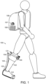
- exoskeleton 100, 600, 900 includes at least one component attached to the body on the distal side of a joint, known as the "distal member” 103, 624, 934, respectively, and at least one component attached to the body on the proximal side of a joint, known as "proximal member” 104, 626, 937, respectively.
- a joint element includes a connection (e.g., pin or bearing, etc.) between the two members that constrains the motion in a manner similar to the anatomical joint.
- the distal member and proximal member are not connected with a joint element, and thus maintain the full range of motion of the anatomical joint.
- distal member 103 FIGs. 1 , 2A and 2B
- 624 FIGs. 6 , 7A and 7B
- 934 FIG.
- proximal members 104, 626, 937 are non-crossing members.
- Ankle and knee exoskeletons of this invention also each have medial crossing members 131, 633 and lateral crossing members 130, 632. These distinctions are made because either the proximal or distal member can be rigidly fixed to the crossing member or include a crossing member.
- the crossing member itself is rigid.
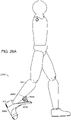
- the crossing member is flexible, as shown, for example, in the device represented in FIGS. 19A and 19B .
- the crossing member such as the crossing member in any of FIGs. 1 , 2A , 2B , 6 , 7A, 7B or 9 , is semi-rigid in that flexibility is tuned for delivering mechanical power amplification, to thereby operate in the manner of, for example, a catapult.
- a "motor,” as that term is employed herein in its broadest sense, is anything that creates work.
- a motor can be a combination of mechanical components that exhibits series elasticity, such as a link between a crossing member and either a proximal or distal member of a wearable device of the invention, and a suitable actuator.
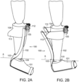
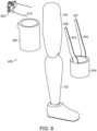
- ankle exoskeleton 100 has distal member 103 connected to foot 101, and a proximal member 104 attached to shank 102.
- Ankle exoskeleton 100 has at least one crossing member, such as crossing members 130, 131.
- Proximal shank member 104 on ankle exoskeleton 100 does not pass through the virtual horizontal plane A ( FIGs. 2A-2B ).
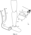
- Distal foot component 103 has both medial crossing member 131 and lateral crossing member 130, with respective attachment points 129, 128 for the electric spool actuator cable 112 ( FIG. 3 ).
- Force exerted by electric spool actuator 105 is measured with force sensor 111 placed between actuator body and proximal shank member 104.
- Proximal shank member 104 includes posterior protrusion 113 that guides crossing members 130, 131 and prevents them from snagging on the calf of shank 102.
- Knee exoskeleton 600 shown in FIGs. 6-8 , includes distal member 624 connected to shank 602, and proximal member 626 attached to the thigh 625.
- Distal shin cuff 624 of knee exoskeleton 600 also has both a medial crossing member 633 and a lateral crossing member 632 with respective cable attachment points 627, 628, as shown in FIG. 8 .
- Proximal thigh member 626 on knee exoskeleton 600 does not pass through the horizontal knee joint plane "B," shown in FIGs. 6 and 7 .
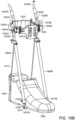
- hip exoskeleton 900 has distal member 934 connected to thigh 625, and proximal member 937 attached to waist 935.
- Hip exoskeleton 900 also has lateral crossing member 936 attached to distal member 934.
- Proximal waist member 937 of hip exoskeleton 900 does not pass through horizontal hip joint plane "C.”
- This exoskeleton includes ball screw actuator 938 to apply both flexion and extension moments about the hip of the individual wearing knee exoskeleton 900.
- a moment is exerted about the respective ankle, knee and hip joints of the individual wearer by connecting a linear actuator to the crossing member and non-crossing member on the non-crossing side of each respective exoskeleton.
- the depicted ankle and knee exoskeletons 100, 600 respectively, show spool actuator 105 spanning crossing members 130, 132 and 630, 632 and respective non-crossing members 104 and 626 on the proximal side of each joint. Cable 112 of spool actuator 105 links crossing members to non-crossing members and applies only a substantially linear force to the crossing members.
- Housing 115 shown in FIGs.
- spool actuator 105 is attached to proximal members 104, 626, ( FIGs. 1 and 6 , respectively), and the actuated cable end is attached to the proximal end of the distal members 128, 129, 627, 628 ( FIGs. 3 and 8 ).
- Spool actuator 115 is discussed in more detail in Section 2.2., in ⁇ ra.
- Hip exoskeleton 900 ( FIG. 9 ) includes a ball screw actuator 938 connected to crossing member 936 and the non-crossing member 937 on the proximal side of the hip joint.
- Connecting a linear actuator to the crossing member and non-crossing member on the non-crossing side of the joint enables a geometry in which shear forces on skin of the individual are reduced, and in which a large lever arm can be achieved, thereby increasing comfort and efficacy.
- the stiffness and geometry of the crossing member(s) is important for flexibility and exoskeleton efficacy.
- the crossing member can either be flexible or rigid in both the sagittal and coronal planes of the individual wearing the device. Flexibility in the sagittal plane lends itself to a series-elastic actuator, and flexibility in the coronal plane increases joint flexibility.
- the crossing member can cross the joint in a variety of configurations.
- the depicted ankle and knee exoskeletons have two crossing members which extend from the distal member and cross the joint on the medial and lateral sides of the joint.
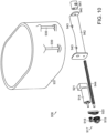
- Hip exoskeleton of FIGs. 9 and 10 has only one lateral crossing member, which crosses the hip joint. The crossing member could also span the joint on the posterior side or anterior side of the individual wearing the device.
- FIGs. 1-4 show a proximal member with tapered back 113, which guides crossing members 130, 131 around shank 102 of the individual.
- actuator 105 can be located on either the distal member or the proximal member of the device. Usually, it is advantageous to place the actuator on the proximal member, to reduce the inertia of the device with respect to the individual's center of mass. This is advantageous from both a metabolic and comfort perspective.
- the same principles can also be applied to bi-articular and multi-joint devices.
- the depicted ankle, knee and hip exoskeletons could be employed simultaneously.
- the proximal member of the ankle exoskeleton can also operate as the distal member of the knee exoskeleton, and the proximal member of the knee exoskeleton can also operate as the distal member of the hip exoskeleton.
- the exoskeleton may require either a bidirectional actuator, an actuator that can apply forces in two directions, or a unidirectional actuator, which can only exert significant forces in one direction.
- a bidirectional actuator allows full control over the joint, but it also involves a greater amount of complexity.
- a unidirectional actuator is more limited in the forces it can exert, but it may be appropriate for joints, which only require large amounts of augmentation in one direction, such as the ankle.
- Spool actuator 105 shown in FIGs. 4 and 5 , employs electric rotational motor 114, such as a brushless motor, with belt transmission "T" to drive spool 116.
- Belt transmission T includes drive pulley 118, spool pulley 119 and belt 120.
- Spool 116 wraps cable element (e.g. string, cable, ribbon, etc.) 112, which exerts a force at the cable ends on, for example, proximal ends 128, 129 ( FIG. 3 ) of crossing members 130, 131, respectively.
- Spool 116 runs on bearings 122 to reduce friction. Cable 112 is guided by pair of rollers 117 ( FIG. 5 ), which run on bearings 123 to reduce friction.
- Spool actuator 105 is unidirectional, but the large lever arm of crossing members 130, 131 ( FIG. 3 ) and the relatively small diameter of spool 116 ( FIG. 5 ) provides efficient and compact transmission.
- the entire actuator system is housed in, for example, compact, low weight aluminum body such as housing 115 ( FIGs. 4 and 5 ).
- Ball screw actuator 938 shown, for example, in FIGs. 9 and 10 is a bidirectional electric actuator that employs rotational brushless electric motor 914 ( FIG. 10 ) and belt drive transmission 917, including drive pulley 918, spool pulley 919 and belt 920, to drive ball screw 944 through ball nut 940.
- Ball screw actuator 938 can also be placed on linear bearings 939, 943 in order to reduce vertical shear on an individual's skin.
- Distal member, or thigh cuff 934 ( FIG. 9 ) is attached at crossing member 936 to ball nut 940 via pin joint 941.
- Linear electric motors (not shown) could also be used as bidirectional actuators.
- the high power density and inherent series elasticity of pneumatic actuators is advantageous in a device of the invention, such as an exoskeleton, prosthesis or orthosis of the invention.
- An air cylinder can be used as either a unidirectional or bidirectional actuator. Pressurized air is inherently elastic and can be exploited as a hardening series elastic element, where the stiffness increases with displacement.
- Inflatable bladders can also be employed as very low mass, high power, unidirectional actuators.
- Actuator valves can be used to control the flow of air through pneumatic actuators. The valves may, for example, be on/off or proportional valves.
- a pneumatic actuator for example, could be powered passively, with a tank of compressed air or an onboard compressor. An onboard compressor could exploit the high energy density of liquid fuels such as hydrogen peroxide, gasoline or diesel.
- the energy source should, preferably, be carried onboard by the individual.
- the energy source can be directly attached to either the proximal member, the distal member, or a separate location, such as a backpack or waist pack 106, as shown in FIGs. 1 , 6 and 9 .
- the energy source can have both a high mass energy density and high volumetric energy density.
- the energy source may be one or a combination of the following: electric battery 108, pressurized air, combustible liquid (gas, diesel, hydrogen peroxide, propane), monopropellant (i.e. hydrogen peroxide), thermal cell, fuel cell or solar cell.
- Onboard microcontroller 107 can use various sensors to autonomously control the exoskeleton.
- the sensors may include the following: at least one of a accelerometer, gyroscope, mechanical pressure sensor 111 ( FIG. 3 ), at least one of a pneumatic pressure sensor, angle sensor, and encoder 121 ( FIGs. 4 and 5 ), and at least one of a strain gauge, voltage sensor, current sensor, force sensitive resistor, EMG electrode, and thermistor (not shown).
- Microcontroller 107 FIGs. 1 , 6 and 9 ) employs these sensors to control the torque, position or velocity (or the relationship between these variables, known as impedance) of actuator 105.
- a device having multiple degrees-of-freedom (DOF) mechanism includes: input component and output components that can be mounted on either side of a limb joint; a multiple DOF linkage system that allows torque transmitted from the input component to the output component; and a slider that connects the output link to the input link and allows the input component and the output component to rotate and translate with respect to each other in the same plane, so that the trajectory of variable instantaneous centers of the two components matches that of the biological joints.
- DOF degrees-of-freedom
- the device of the invention includes a ground link that is fixed relative to either a distal end of a human femur or a proximal end of a human tibia.
- An input link having a first end and a second end is fixed to and rotates about a pivot defining an axis of rotation, wherein the pivot links the input link at the first end to the ground link.
- a coupler having a first end and a second end is pivotally mounted to the second end of the input link.
- An output link is fixed relative to the other of the distal end of the human femur or the proximal end of the human tibia and has a first end and a second end, the first end being pivotally mounted at the first end to the second end of the coupler.
- a sliding link is located between the ground link and the output link, whereby rotation of the human knee joint to which the device is secured will cause translation of an axis of rotation of the output link relative to the ground link to track two degrees of freedom of the human knee joint, wherein the human knee joint rotates in a sagittal plane about an axis that is normal to the sagittal plane but which moves relative to the axis of rotation of the pivot linking the first end of the input link to the ground link.
- the sliding link includes a slot defined by the output link, wherein a protrusion from the ground link extends through the slot defined by the sliding link, the sliding link restricting movement of the axis of rotation of the output link to a line normal to an axis of rotation of the pivot.
- One purpose of this invention is to modify the force distributions of an exoskeleton, orthosis or prosthesis on a limb.
- the intent is to alter the forces such that they are no longer parallel to the axis of the limb, but instead, perpendicular to the axis, whereby loading will be substantially more comfortable.
- Another purpose of this invention is to transmit planetary torques from either active or passive devices to limbs without altering the normal biological joint motions.
- the intent is to apply torques to a limb by utilizing an unconstrained multiple DOF mechanism, thereby providing an adaptive trajectory of instantaneous centers of the device matching that of the biological joints.
- the device of the present invention employs a geometric configuration that does not require artificial joints, therefore, making the device more comfortable and lighter.
- the comfort and weight of the device of the invention plays a large role in its ability to augment or rehabilitate the physical capabilities of an individual wearing the device.
- the device of the invention can constrain the linkage system and set trajectories of instantaneous centers of the device in accordance with normal biological joint motions while the external sources apply torques to the joint at the same time.
- mismatch between limb joint motion and mechanical interface motion is largely avoided, as well as skin shear force, undesired slippage and sluggish interaction between the individual and the device.
- the device of the invention can also act in the sagittal plane so that external sources can apply torques to joints of the individual without impeding rotation of the joint in the other planes, i.e., coronal or transverse planes.
- external sources can apply torques to joints of the individual without impeding rotation of the joint in the other planes, i.e., coronal or transverse planes.
- a force balance transmission is maintained in the sagittal plane of the individual so that external sources can apply torques to the biological joint in the sagittal plane without impeding rotation of the biological joint in the other two planes.
- the device of the invention also avoids significant skin shear force at the mechanical interface with the individual wearer. As a result, mismatch between ankle joint motion, for example, and mechanical interface motion is substantially avoided, as well as undesired large additional inertia added by the device of the invention.
- Enhancement may center on modification of ambulation of able-bodied persons or individuals with movement pathology.
- the invention can enhance locomotory function beyond what is otherwise physiologically possible.
- physical enhancement could be employed to assist professional duties (such as military or civil service duties), athletic achievement, recreation, or other opportunities.
- gait dysfunction resulting from movement pathology such as Parkinson's disease or knee osteoarthritis, or restoration of age-related reduced locomotory function could be treated or relieved by this invention.
- FIGs. 11A through 11E One embodiment of this invention is represented in FIGs. 11A through 11E as a topology of a two-DOF five-bar linkage system 1100 that provides a kinematic constraints that includes ground link 1101, input link 1102, coupler 1103, output link 1104, slider 1105, pivot joints 1110, 1123, 1134 and 1145, wherein connections are provided between ground link 1101 and input link 1102, between input link 1102 and coupler 1103, between coupler 1103 and output link 1104, and between output link 1104 and slider 1105, via pivot joints 1110, 1123, 1134 and 1145, respectively.
- ground link 1101, input link 1102, coupler 1103, output link 1104, slider 1105, pivot joints 1110, 1123, 1134 and 1145 wherein connections are provided between ground link 1101 and input link 1102, between input link 1102 and coupler 1103, between coupler 1103 and output link 1104, and between output link 1104 and slider 1105, via pivot joints 1110, 1123, 1134 and 1145, respectively.
- Ground link 1101 as the proximal mount, is fixed to the main proximal component of the limb joint, and output link 1104, as the distal mount, is fixed to the main distal component of the joint.
- Input link 1102 exerts both flexion and extension moments about the j oint.
- Slider 1105 translates with respect to ground link 1102 along a virtual or physical track at ground link 1101, which allows a virtual instantaneous center of input link 1102 and output link 1104.
- the track can be linear or curved. With an unfixed rotational axis, torques can still be applied to the limb from input link 1102 to output link 1104 via unconstrained two-DOF linkage system 1100. Tracking at ground link 1101 is not necessarily linear. FIGs.
- 11D-E are superimposed on a biological knee joint. See, Kuan, J.; Pasch, K.A.; Herr, H.M., "Design of a Knee Joint Mechanism that Adapts to Individual Physiology," Engineering in Medicine and Biology Society (EMBS), 2014, 36th Annual International Conference of the IEEE, pp. 2061-2064, 26-30 Aug. 2014 .
- EMBS Engineering in Medicine and Biology Society
- FIGs. 12A and 12B are topological representation systems 1200 of the invention in first and second positions where the linkage system includes a pure rotational constraint.
- the lengths of input link 1102 and output link 1104 are set as the same, so that the linkage system performs pure rotation motion when the biological joint and pivot joint 1110 are coaxial.
- the biological joint regarded as a single one-DOF kinematic pair constrains the linkage system and sets the fixed rotational axis of the device in accordance with normal biological joint motion.
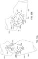
- FIGs. 13A and 13B show a possible configuration of a two-DOF five-bar linkage system 1300 applied to knee joint 1302.
- Femur 1350 of knee joint 1302 is fixed to ground link 1304 and tibia 1360 is fixed to output link 1316.
- Ground pivot 1306 pivotally links ground link 1304 to input link 1308.
- Pivot 1310 pivotally links input link 1308 to coupler 1312.
- Coupler 1312 is pivotally linked to output link 1316 at pivot 1314.
- virtual center of rotation A of output link 1316 is centered with ground pivot 1316, as illustrated in FIG. 13A .
- FIG. 13A As can be seen in the transition from FIG. 13A to FIG.
- knee joint 1302 can rotate and translate in the same plane, and thereby provide an adaptive trajectory of instantaneous centers of rotation (between ground pivot 1306 and virtual center of rotation A) matching that of the tibia about the biological knee joint.
- the overall system can be considered a one-DOF five bar-linkage system.
- the knee joint can be regarded as a crank-rocked pair that constrains the linkage system and sets a specific trajectory of instantaneous centers of rotation of the device in accordance with normal knee joint motion. As a result, the mismatch between limb joint motion and mechanical interface motion can be avoided.
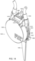
- joint mechanism 1400 includes cable conduit anchors 1402 and drum housing 1410, driven drum 1423 and torque sensor 1451, screw 1468, proximal mount 1464, output link 1463, and rotary optical encoder modules 1470, 1471, 1472.
- Proximal mount 1464 is fixed to the brace attached to the wearer's proximal limb while output link 1463 is fixed to the brace attached to the wearer's distal limb. Accommodated within track 1631 ( FIG.
- screw 1468 is fixed to proximal mount 1464 and acts like slider 1105 and ground link 1101 pair in the topology in FIG. 11 , and causes output link 1463 to translate with respect to proximal mount 1464 along track 1631 of output link 1463, as a variable instantaneous center rotation between input link 1460 and output link 1463.
- bearing caps 1466 with screws 1467 two roller bearings 1465, mounted on sink hole 1632 of output link 1463 and input link 1460, are used to allow an individual to slightly move the limb forward or away from the midline of the body while providing torque flexing or extending the limb joint.
- Joint mechanism 1400 With an unfixed rotational axis, torques can still be applied to the limb from input link 1460 to output link 1463 via the unconstrained two-DOF linkage system.
- Joint mechanism 1400 therefore, provides specific planar constraints when there is a mismatch between rotational axes of a limb joint, such as a biological knee joint, and as a mechanical interface.
- FIG. 18A the mechanism provides pure rotational constraints when there is no mismatch between limb joint and mechanical interface.
- FIG. 18B the mechanism provides specific planar constraints when there is a mismatch between the rotational axes of the limb joint and the mechanical interface.
- driven drum 1423 is actuated by inner cable 1510 in a pull-pull configuration, driving the limb joint via torque sensor 1451 and output link 1463 with small friction due to four-point contact bearing 1421 incorporated in drum housing 1410.
- Driven drum cap 1420 is fixed to driven drum 1423 by screws 1422 and bearing cap 1432 is fixed to drum housing 1410 by screws 1433. They are used to set a constraint on the linear motions between bearing 1421 and driven drum 1423.
- a four-point contact bearing 1421 can also resist high radial force caused by cable tension.
- a torque sensor includes a series rotatory spring 1451 connecting driven drum 1423 to input link 1460. Inner part of spring 1451 is secured to input link 1460 and torque sensor mount 1450 by screws 1461. Rotatory encoder disk 1470 is mounted on encoder disk mount 1474 by screws 1473. Encoder disk mount 1474 is secured on torque sensor mount 1450 by screws 1475. Four-point contact bearing 1431 is used between torque sensor mount 1450, encoder disk mount 1474 and driven drum 1423 to provide only relative rotational motions between driven drum 1423 and spring 1451. Rotatory encoder disk 1470, encoder disk mount 1474, torque sensor mount 1450, spring 1451, and output link 1460 rotate simultaneously.
- Encoder reader 1472 mounted on drum housing 1410 by screws 1477, can measure the relative rotational angles between drum housing 1410 and the input link 1460. Outer part of spring 1451 is secured on driven drum 1423 by screws 1452. Encoder reader 1471, mounted on driven drum cap 1420 by screws 1477, can measure the relative rotational angles between the input end and the output end of spring 1451, and thus is used to measure the output torque. Cover 1480 is used to protect encoder readers 1471, 1472 and encoder disk 1470. Using a digital encoder to measure the strain caused by output torque reduces the effect of the electromagnetic field. The torque sensor and the encoder can collect the joint state as the feedback information for both real-time control and subsequent analyses. For instance, the control scheme mentioned in part I can be used to control the mechanical joint.
- the invention is directed to an ankle joint exoskeleton or assistive device that physically interfaces with an individual without adding significant inertia on human legs, while wherein for example, mismatch between ankle joint motion and mechanical interface motion is in the same plane, and avoiding skin shear force.
- three-DOF mechanism configurable to be mounted to an individual's shank and foot, has a force balance transmission that allows an ankle joint to perform external-internal rotation and inversion-eversion rotation while applying a torque in the sagittal plane, so the attached biological ankle joint can maintain a normal gait.
- the crossing member is not rigid.
- the link includes a strut extending from the proximal member to the distal member, whereby the crossing member and the strut span the axis about which the distal member rotates.
- the strut is constrained at the proximal member normally and laterally to a major longitudinal axis of the crossing member extending from the proximal number to the distal member, wherein the strut is not restricted along the major longitudinal axis of the crossing member.
- the link further includes at least one roller at the proximal member that constrains the strut normally and laterally.
- the link includes at least one pair of rollers in opposition to each other, wherein the strut is normally constrained between the pair of rollers.
- the strut can be curved at the pair of rollers, whereby shear force between the strut and pair of rollers during rotation of the distal member of the axis spanned by the crossing member and the strut is less than it would be if the strut were straight at the pair of rollers.
- the strut includes a guide tube at the pair of rollers, wherein the crossing member extends through the guide tube.
- the device includes a pair of crossing members and a pair of struts.
- the struts are essentially straight between the rollers and the distal member.
- At least one of the struts deflects during eversion and inversion of the human foot secured to the distal member and a human calf secured to the proximal member.
- the struts are rigid.
- the struts are curved, whereby the struts operate as series springs during a normal walking cycle of human foot secured to the distal member and the human calf secured to the proximal member.
- the link further includes a winch actuator assembly attached to a proximal end of the pair of crossing members, whereby actuation of the link will cause retraction of the crossing member, which causes rotation of the distal member and plantar flexion of the human foot secured to the distal member about a human ankle joint.
- the pair of crossing members is fixed to a proximal end of the distal member.
- a second pair of crossing members can be fixed to a distal end of the distant member.
- the link further includes a second winch actuator assembly attached to a proximal end of the second pair of crossing members, whereby selective actuation of the link causes retraction of the second pair of crossing members, which causes rotation of the distal member and dorsiflexion of the human foot secured to the distal member about the human ankle joint.
- the distal members are configured to fit the human calf.
- the proximal member can be configured to fit the human thigh.
- the crossing member extends proximally from the distal member, and the link extends between the proximal member and a proximal end of the crossing member, whereby actuation of the link will cause extension of a human leg secured to the proximal and distal members.
- the crossing member extends distally from the proximal member and the link extends between a distal end of the crossing member and the distal member, whereby actuation of a link will cause extension of the human leg secured to the proximal and distal members.
- the proximal member is configured to fit a human waist.
- the distal member is configured to fit a human thigh.
- the crossing member extends proximally from the distal member.
- the link includes a bidirectional actuator, whereby actuation of the link will rotate the distal member and a human thigh secured to the distal member about a hip joint of a human wearing the device.
- the bidirectional actuator is a ball screw actuator.
- an ankle joint device 1900 includes shank guard component 1902 mounted on an anterior shank of an individual, output component 1904 configured to fit the individual's foot, and transmission component 1906, or crossing member, transmitting torque from an input component such as a motor and coil (not shown) linked to cord 1910, which is linked to output component 1904.
- Shank guard component 1902 includes shank brace 1921, two pairs of rollers 1923A, 1923B, two roller mounts 1920A, 1920B, fastening strap 1925, and two position sensors 1950A, 1950B.
- Output component 1904 includes shoe 1960, nylon tube 1962 and axle 1964.
- the transmission component 1906 includes a pair of curved guide tubes 1940A, 1940B, two cable conduits 1930A, 1930B, two output rods 1968A, 1968B, two rod end clamps 1970A, 1970B, and cord 1910.
- Roller mounts 1920A, 1920B are fixed to the each side of brace 1921, and fastening strap 1925 wraps itself around the loops of two roller mounts 1920A, 1920B, forming a loop that an individual can put on as a conventional shank guard. After putting it on, the individual can adjust fastening strap 1925 to make a proper fitting.
- Rear rollers of roller pairs 1923A and 1923B are fixed to pins on roller mounts 1920A, 1920B, and two moving pins 1924A, 1924B that slide along the slots on roller mounts 1920A, 1920B confine the movements of the front rollers along the roller mounts 1920A, 1920B, allowing some mismatched alignments of curved guide tubes 1920A, 1920B and rollers 1923A, 1923B due to contact area changes.
- output rod 1968A is clamped to one end of curved guide tube 1940A and the other end is clamped to rod end clamp 1970A by cap screws.
- One end of output rod 1968B is clamped to one end of curved guide tube 1940B and the other end is clamped to rod end clamp 2320B by cap screws, as well.
- Spherical bearing rods 1972A, 1972B are screwed to rod end clamps 1970A, 1970B, and attached to the each end of axle 1964 through the front outsole of boot 1960 via clips 1974A, 1974B, respectively. Screws and a taped axle can be used to secure rod end clamps 1970A, 1970B to the axle without using clips 1974A, 1974B.
- Spherical bearing rods 1972A, 1972B transmit the force generated by cable conduits 1930A, 1930B from two output rods 1968A, 1968B, to shoe 1960 and allow the ankle to voluntarily perform eversion, inversion, and external and internal rotation.
- the other ends of curved guide tubes 1940A, 1940B are fixed to the end pieces of cable conduits 1930A, 1930B, respectively.
- roller mounts 1920A, 1920B confine pairs of rollers 1923A, 1923B, respectively, providing normal and lateral forces to constrain each curved guide tubes 1940A, 1940B in the sagittal plane while still allowing the curved guide tubes 1940A, 1940B to freely move upward and downward through a full range of motion.
- Alternative ways of accomplishing the same motion accompanied by zero shear force include attaching rollers to the guided bar that can move up and down a designed curved track on the roller mounts, letting the point of horizontal force move up and down the shank; and variation of a Chebyshev straight line mechanism that has two trusses or cords connecting two points of the guided tube to two points of the shank guard can also achieve the same function with designed parameters.
- cord 1910 connects to the input source via two cable conduits 1930A, 1930B.
- cord 1910 runs from an input source via cable conduit 1930A, through the hole of guide tube 1940A, nylon tube 1962 anchored in the boot heel, other guide tube 1940B, and back to the input source via other cable conduit 1930B.
- the input source can pull cord 1910, and then output rods 1968A, 1968B to transmit the force from the input source to shoe 1960 and then apply the torque to the ankle joint in the sagittal plane.
- Nylon tube 1962 allows the cord 1910 to equally distribute an input force to the each side of the shoe 1960 even when the ankle performs eversion and inversion rotation.
- Two position sensors 1950A, 1950B are used to measure the displacement of guide tubes 1940A, 1940B so as to measure angles of the plantar-dorsal flexion and inversion-eversion.
- the linear potentiometers and encoders can also be used to measure the displacement of guided tubes 1940A, 1940B.
- the ankle angle can be directly measured by using an electro goniometer or inertial measurement units.
- the force/torque sensing can be achieved by using in-line cable tension sensors attached to cord 1910, conduit housing compression sensors attached to curved guided tube 1920A, 1920B, strain gauges attached to roller mounts 1920A, 1920B or the output rods 1968A, 1968B, built-in spherical bearing force sensors, or springs, for example.
- the output rods 1968A, 1968B can be curved or slender, so they act like series springs, increasing the force controllability and the level of safety as well as acting a force-sensing device.
- an arch spring or strut can also be introduced to replace rigid axle 1964. It can also act as a force sensing mechanism by measuring deformation and using Hook's law. Referring back to FIGs. 19A and 19B , simple struts that attach near ankles with side bars or plates on the shoe 1960 can also be used to reinforce the force transmission of the device.
- the device can only apply unidirectional torque to ankles, but bidirectional torque can be applied to ankles by attaching another cord running from the actuation source to the front outsole of the shoe 1960 or to the designed structure fixed to the shoe 1960.
- Another way is to replace cord 1910 and cable conduits 1930A, 1930B with a flexible transmission and two rigid members, so the device can be operated at a pull-push configuration, actuating ankles in the both plantar flexion and dorsiflexion directions.
- the range of motion of the device is set to allow a normal wearer to walk or run at self-selected speed.
- the device on each leg is very lightweight compared to the existing devices, but it is capable of providing large torques via cable driven actuation or an onboard motor because of a large moment arm from the nylon tube anchor point to the axle.
- a foot switch can be used to determinate when to apply torque to the ankle to reduce the metabolic cost.
- the invention can be further modified to act as a passive device without any power or as a quasi-passive device that requires little power.
- the module can further be used as a measurement tool for estimating biological properties of an ankle.
- a wearable lower limb device that includes a distal module wearable by an individual that spans a distal skeletal joint and a proximal module wearable by the individual that spans a proximal skeletal joint, wherein the distal module and the proximal module are coupled.
- At least one of the distal and proximal modules includes a distal member wearable by the individual distal to the respective skeletal j oint, a proximal member wearable by the individual proximal to the respective skeletal joint, and a link between the distal and proximal members, whereby actuation of the link will be translated to a force at the distal or proximal member that is normal to a major longitudinal axis extending through the distal and proximal members.
- at least one of the other of the distal member and proximal member includes a crossing member, and the link extends from the crossing member of the distal member or the proximal member to the other of the distal member or the proximal member.
- both the distal module and the proximal module include a distal member, a proximal member, a crossing member and a link.
- the distal module and the proximal module can be coupled by a common member, wherein the proximal member of the distal module is also at least a component of the distal member of the proximal module.
- the distal module and the proximal module can be rigidly coupled.
- the common member includes a degree of freedom coupling the distal module to the proximal module.
- the degree of freedom can be a hinge causing rotation in a plane essentially parallel to a plane of rotation of at least one of the proximal module and distal module.
- the distal module can be, for example, an exoskeleton, orthosis or prosthesis configured for use with a human knee joint, while the proximal module can be an exoskeleton, orthosis or prosthesis configured for use with a human hip joint.
- the link of the distal and proximal modules can each include a winch actuator or a ballscrew actuator.
- the crossing member of the distal module includes a pulley and a cord linking the pulley, and a link of the distal module includes a winch actuator, whereby actuation of the link of the distal module causes extension of the human knee secured to the distal module.
- the distal member of the distal module can include, for example, a leaf spring linking the pulley to the distal member of the display module.
- the crossing member of the distal module extends proximally from the hinge of the distal member of the proximal module.
- the link of the proximal module can include a cord and a winch actuator that is at the proximal member of the proximal module, wherein the cord extends from the crossing member of the proximal module to the winch actuator, whereby actuation of the link of the proximal module will cause flexion movement of a human hip secured to the proximal module.
- the link of the proximal module includes a ball screw actuator, whereby actuation of the link is bidirectional and, selectively causes flexion and extension of a human hip secured to the proximal member.
- the lower limb device further includes an ankle module that is distal to the distal module, wherein the ankle module is coupled to the distal module, and wherein the distal module and the ankle module share a common member.
- the ankle module includes an ankle distal member, an ankle proximal member, and an ankle link between the ankle distal number and the ankle proximal member, whereby actuation of the ankle link will be translated to a force at the ankle distal member or the ankle proximal member that is normal to a major longitudinal axis extending through the ankle distal end ankle proximal members.
- At least one or the other of the ankle distal and the ankle proximal member includes an ankle crossing member, wherein the ankle link extends from the ankle crossing member of the ankle distal member or the ankle proximal member to the other of the ankle distal member or the ankle proximal member.
- the crossing member of the ankle module extends proximally from the distal member of the ankle module.
- the link of the ankle module includes a winch actuator at the proximal member of the ankle module, wherein a cord of the winch actuator extends from a proximal end of the crossing member to the winch actuator of the ankle module, whereby actuation of the link causes plantar flexion of human ankle secured to the ankle module.
- the lower limb device of the invention can be, for example, an exoskeleton, orthosis or prosthesis for a human ankle, and the proximal module can be an exoskeleton, orthosis or prosthesis for a human knee.
- lower limb exoskeleton 2100 ( FIG. 21 ) includes modular sections that attach to an individual's waist 2101, thigh 2109, shank 2118, and foot 2123.
- Exoskeleton 2100 includes unidirectional winch actuators 2102, 2107 and 2119, to apply moments about the individual's hip, knee and ankle joints respectively.
- Exoskeleton 2100 applies a plantar-flexion moment about the individual's ankle, an extension moment about the knee, and a flexion moment about the hip.
- the unidirectional winch actuators apply mechanical power to the individual, while also permitting the individual completely transparent control.
- Exoskeleton 2100 can also apply zero torque to the individual by providing excess slack in cords, 2104, 2113, 2124, and 2126 ( FIGs. 21-22 ). Additionally, winch actuators 2105, 2107 and 2119 preserve joint flexibility and do not constrain the hip, knee or ankle joints to planar motion, respectively. Flexible levers 2122, 2117 and 2105 which are built into exoskeleton 2100 are employed as series elastic elements to increase actuator shock tolerance, electrical energy efficiency, and peak exoskeleton power. The joint-specific design of exoskeleton 2100 results in a selectively low mass device that can apply substantial amounts of power to the individual.
- ankle portion 2200 of exoskeleton 2100 includes boot attachment 2202 and shank-mounted winch actuator 2119.
- Ankle module 2200 of the exoskeleton provides plantar-flexion moment about the ankle joint by actuating flexible levers attached to the boot.
- Elastic lever arm 2122 is integrated into boot 2202 by connection points at both the toe 2228 and heel 2230. Since exoskeleton 2100 only applies plantar-flexion moments, the connection between the heel and lever arm 2229 can be slender and lightweight.
- Boot attachment 2202 can be made of a variety of materials including, for example, carbon fiber and fiberglass composites. The flexibility of lever arm 2229 and winch actuation also maintains the ability of the individual's ankle to perform biological eversion and inversion movements.
- Anteriorly mounted winch actuator, 2119 is connected to a lightweight shin guard 2120, which is secured to the individual's calf with lightweight strap 2221.
- Shin mount 2225 extends from shin guard 2520 and serves to dissipate force.
- Knee module 2300 shown in FIG. 23 , includes large diameter pulley 2115 to apply an extension moment about the knee joint while maintaining a full range of motion. Knee exoskeleton 2300 utilizes large pulley 2115 to apply an extension moment about the knee while maintaining full knee range of motion.
- Knee actuator mount 2392 is connected to thigh cuff 2110 via rotary bearing 2108 to reduce knee constraints. Minimal shear and joint flexibility is achieved by including a bearing 2108 between knee actuator mount 2332 and thigh cuff 2110.
- Knee actuator mount 2332 houses knee winch actuator 2107, knee actuator electronics 2331, and upper and lower cord guides 2111 and 2114, respectively. Knee actuator mount 2332 is connected to the shank leaf spring 2117 via rotary bearing 2116.
- Additional rotary bearing 2108 minimizes the constraint on the knee joint imposed by knee bearing 2116.
- a linear bearing could also be used instead of rotary bearing 2108.
- rotary bearing could be placed between flexible lever 2117 and shin guard 2120. Thigh cuff 2110 is secured to the body with lightweight straps 2106, 2112.
- hip exoskeleton module 2400 employs elastic lever 2105 to store energy in the sagittal plane of the individual while allowing hip adduction/abduction and rotation. Similar to ankle exoskeleton 2200, hip exoskeleton 2400 employs an extended thigh lever arm 2105 to provide a geometric transmission to hip actuator 2102. Hip actuator 2102 routes cord 2104 around idler roller 2103 and is connected to thigh extension lever 2105. Hip actuator 2400 is attached to waist mount 2340 that is secured to the individual with strap 2339. The geometry of thigh extension lever 2105 allows for both hip flexibility and actuation.
- a suitable hip actuator can be, for example, winch actuator 2500, shown in FIG. 25 , which employs high torque electric motors to efficiently and quietly actuate the joints.
- Winch actuator 2500 allows the exoskeleton to apply large amounts of the power to the individual wearer during certain portions of gait, and then apply zero torque during other portions of gait, which is a convenient feature for control.
- a conventional radial flux brushless motor or an axial flux brushless motor, for example, can be employed to actuate the exoskeleton module.
- Motor 2536 supported by rotational bearings 2535, wraps cord 2524 around an integrated spool.
- Motor cap 2537 houses the electromagnetics of motor 2536 and attaches motor 2538 to the actuator body 2534.
- Cord 2524 is routed around idler rollers 2527, supported by bearings 2533.
- FIGs. 26A and 26B An embodiment of a device of the invention that includes an ankle exoskeleton with a pneumatic actuator is illustrated in FIGs. 26A and 26B .
- Ankle exoskeleton 2600 has distal member 2603 connected to foot 101, and a proximal member 2604 attached to shank 102.
- Proximal shank member 2604 on ankle exoskeleton 2600 does not pass through a virtual horizontal plane of the ankle j oint, such as virtual horizontal plane A illustrated in FIGs. 2A-2B .
- Distal foot component 2603 includes crossing member 2630 which is linked to proximal member 2604 via inflatable bladder actuator 2605.
- Force exerted by inflatable bladder actuator 2605 can be measured with a force sensor placed between actuator 2605 and proximal shank member 2604, similar to force sensor 111 described with reference to FIG. 3 .
- Inflation of the bladder actuator 2605 causes plantar flexion of the ankle joint, as illustrated in FIG. 26A .
- Deflation of bladder actuator 2605 allows for dorsiflexion of the ankle joint, as illustrated in FIG. 26B .
- Valves (not shown) can be employed to effect inflation and deflation of bladder actuator 2605.
- the valves can be actuated by a controller, such as controller 107 described with respect to FIG. 1 .
- An energy source to drive bladder actuator 2605 can be directly attached to proximal member 2604, distal member 2603, or a separate location, such as backpack or waist pack 106, as shown in FIG. 1 .
Description
- This application claims the benefit of
U.S. Provisional Application No. 61/916,692, filed on December 16, 2013 U.S. Provisional Application No. 62/014,377, filed on June 19, 2014 - This invention was made with Government support under Grant No. NNX12AM16G awarded by the National Aeronautics and Space Agency. The Government has certain rights in the invention.
- Exoskeletons, orthoses and prostheses are intended to enhance human function, often in the context of locomotory motion. Exoskeletons, for example, are worn on the body exterior, around a biological joint that is the target of an intended function (e.g., knee or hip). Depending on the exact purpose of the device, the mechanical effect of the exoskeleton may be to add, remove or store and release energy. Irrespective of purpose, however, all exchange of energy between a human user and a worn exoskeleton occurs through mechanical interaction between the exoskeleton and the human body. The mechanical interaction imparts force distributions on the soft tissue surrounding the joint and limb segments. Typically, the exoskeleton uses a mechanical joint in parallel with the anatomical joint, which reduces flexibility, or the force distributions are parallel to the axis of the limb (i.e. shear), which may be uncomfortable to the user. This discomfort often disrupts device function and hinders the efficacy of the exoskeleton.
- International Application number
WO2012/175211 A1 describes a fully integrated system with artificial joints. Artificial joints generally reduce forces exerted on the human body, but often also greatly constrain motion and flexibility. Known powered exoskeletons are also typically heavy and cumbersome to use. - Conventional exoskeleton and assistive devices usually consist of active actuators, passive mechanical components, and mechanical interfaces. In order to reduce design complexity, limb joints are usually considered as one-to-three degrees of freedom (DOF) joints of multiple single DOF hinge joints in a single plane. However, biological joints are complex and usually rotate with respect to a changing instantaneous center. For example, knee motion may be visualized as rotation of a femur about a series of three-dimensional instantaneous axes rather than a single fixed axis. As a result, a mismatch between limb joint motion and mechanical interface motion typically leads to undesired ligament and muscle length changes and other internal mechanical changes. Those undesired effects contribute to discomfort, as well as to slippage and sluggish interaction with such devices.
- Therefore, a need exists for devices, such as exoskeletons, orthoses and prostheses that overcome or minimize the above-referenced problems. The patent application
WO 2009/149206 discloses a therapeutic method and device for rehabilitation whereby a subject-controllable range of joint motion is extended, and subject control of joint movement within a range of motion is increased. However slippage of the wearable device on the user's body still need to be avoided. - The invention is generally directed to a wearable device, such as a prosthesis, orthosis or exoskeleton, such as for use with the human biological ankle, knee or hip, or a lower limb of any combination of the human ankle, knee and hip. In one embodiment, the device includes a distal member wearable by an individual distal to a skeletal joint of the individual, a proximal member wearable by the individual proximal to the joint and a link between the distal and proximal member. One or the other of the distal member and the proximal member includes a crossing member, wherein the link extends from the crossing member of the distal member or the proximal member to the other of the distal member or the proximal member. Actuation of the link translates to a force at the distal or proximal member that is normal to a major longitudinal axis extending through the distal and proximal members when worn by the human individual.
- In one embodiment, the crossing member is rigid. The crossing member can be rigidly or not rigidly fixed to one or the other of the distal member and the proximal member.
- In a specific embodiment, the link includes a ball screw actuator. In another embodiment, the link and the crossing member are components of a series elastic actuator. The series elastic actuator can be, for example, a bidirectional actuator, such as a pneumatic actuator. An example of a suitable pneumatic actuator for use with the present invention includes a hardening series elastic element. In another embodiment, the pneumatic actuator includes an inflatable bladder. In still another embodiment, the series elastic actuator is a unidirectional actuator, such as a pneumatic actuator or an electric spool actuator.
- The crossing member can include the distal end and proximal end, wherein the distal end is fixed to the distal member at one end and is essentially normal to a major longitudinal axis of the distal member, and wherein the link extends between the proximal end of the crossing member and the proximal member. In a specific embodiment, the distal member includes a surface that is essentially parallel to a plane that is normal to the major longitudinal axis extending between the distal and proximal members. In one embodiment, the device of the invention further includes a second crossing member extending from the distal member, wherein the crossing members are essentially parallel to each other.
- In one embodiment of the invention, the distal member is configured to support and to be secured to a human foot, wherein the crossing members are configured to extend essentially dorsally and parallel to a tibia extending from the human foot, and wherein the proximal member is secured to a calf of the human, wherein an electric spool actuator includes a cable that is linked to the proximal end of the crossing member and spans the calf normally to a major longitudinal axis of the human tibia, whereby actuation of the actuator causes rotation of the distal member about human ankle joint to thereby at least assist plantar flexion of the human foot while walking.
- In another embodiment, the crossing member is not rigid. In this embodiment, the link includes a strut extending from the proximal member to the distal member, whereby the crossing member and the strut span the axis about which the distal member rotates. In a specific embodiment, the strut is constrained at the proximal member normally and laterally to a major longitudinal axis of the crossing member extending from the proximal number to the distal member, wherein the strut is not restricted along the major longitudinal axis of the crossing member. In this embodiment, the link further includes at least one roller at the proximal member that constrains the strut normally and laterally. The link includes at least one pair of rollers in opposition to each other, wherein the strut is normally constrained between the pair of rollers. The strut can be curved at the pair of rollers, whereby shear force between the strut and pair of rollers during rotation of the distal member of the axis spanned by the crossing member and the strut is less than it would be if the strut were straight at the pair of rollers. The strut includes a guide tube at the pair of rollers, wherein the crossing member extends through the guide tube. In one embodiment, the device includes a pair of crossing members and a pair of struts. In a specific embodiment, the struts are essentially straight between the rollers and the distal member. In one particular embodiment, at least one of the struts deflects during eversion and inversion of the human foot secured to the distal member and a human calf secured to the proximal member. Typically, the struts are rigid. In one embodiment, the struts are curved, whereby the struts operate as series springs during a normal walking cycle of human foot secured to the distal member and the human calf secured to the proximal member.
- In one embodiment, the link further includes a winch actuator assembly attached to a proximal end of the pair of crossing members, whereby actuation of the link will cause retraction of the crossing members, which causes rotation of the distal member and plantar flexion of the human foot secured to the distal member about a human ankle joint. In another embodiment, the pair of crossing members is fixed to a proximal end of the distal member. A second pair of crossing members can be fixed to a distal end of the distant member. In one specific embodiment, the link further includes a second winch actuator assembly attached to a proximal end of the second pair of crossing members, whereby selective actuation of the link causes retraction of the second pair of crossing members, which causes rotation of the distal member and dorsiflexion of the human foot secured to the distal member about the human ankle joint. In a specific embodiment, the distal members are configured to fit the human calf. In this embodiment, the proximal member can be configured to fit the human thigh. In one embodiment, the crossing member extends proximally from the distal member, and the link extends between the proximal member and a proximal end of the crossing member, whereby actuation of the link will cause extension of a human leg secured to the proximal and distal members. Alternatively, the crossing member extends distally from the proximal member and the link extends between a distal end of the crossing member and the distal member, whereby actuation of a link will cause extension of the human leg secured to the proximal and distal members.
- In another embodiment, the proximal member is configured to fit a human waist. In this embodiment, the distal member is configured to fit a human thigh. Preferably, the crossing member extends proximally from the distal member. In one such embodiment, the link includes a bidirectional actuator, whereby actuation of the link will rotate the distal member and a human thigh secured to the distal member about a hip joint of a human wearing the device. In one embodiment, the bidirectional actuator is a ball screw actuator.
- Another embodiment of the device is a wearable lower limb device that includes a distal module wearable by an individual that spans a distal skeletal joint and a proximal module wearable by the individual that spans a proximal skeletal joint, wherein the distal module and the proximal module are coupled. At least one of the distal and proximal modules includes a distal member wearable by the individual distal to the respective skeletal joint, a proximal member wearable by the individual proximal to the respective skeletal joint, and a link between the distal and proximal members, whereby actuation of the link will be translated to a force at the distal or proximal member that is normal to a major longitudinal axis extending through the distal and proximal members. In this embodiment, optionally, at least one of the other of the distal member and proximal member includes a crossing member, and the link extends from the crossing member of the distal member or the proximal member to the other of the distal member or the proximal member. In one specific embodiment, both the distal module and the proximal module include a distal member, a proximal member, a crossing member and a link. The distal module and the proximal module can be coupled by a common member, wherein the proximal member of the distal module is also at least a component of the distal member of the proximal module. The distal module and the proximal module can be rigidly coupled. In one embodiment, the common member includes a degree of freedom coupling the distal module to the proximal module. For example, the degree of freedom can be a hinge causing rotation in a plane essentially parallel to a plane of rotation of at least one of the proximal module and distal module. The distal module can be, for example, an exoskeleton, orthosis or prosthesis configured for use with a human knee joint, while the proximal module can be an exoskeleton, orthosis or prosthesis configured for use with a human hip joint. In a specific embodiment, the link of the distal and proximal modules can each include a winch actuator or a ball screw actuator. In one particular preferred embodiment, the crossing member of the distal module includes a pulley and a cord linking the pulley, and a link of the distal module includes a winch actuator, whereby actuation of the link of the distal module causes extension of the human knee secured to the distal module. The distal member of the distal module can include, for example, a leaf spring linking the pulley to the distal member of the display module. In one embodiment, the crossing member of the distal module extends proximally from the hinge of the distal member of the proximal module. The link of the proximal module can include a cord and a winch actuator that is at the proximal member of the proximal module, wherein the cord extends from the crossing member of the proximal module to the winch actuator, whereby actuation of the link of the proximal module will cause flexion movement of a human hip secured to the proximal module. In an alternate embodiment, the link of the proximal module includes a ball screw actuator, whereby actuation of the link is bidirectional and, selectively causes flexion and extension of a human hip secured to the proximal member.
- In another embodiment, the lower limb device further includes an ankle module that is distal to the distal module, wherein the ankle module is coupled to the distal module, and wherein the distal module and the ankle module share a common member. In one embodiment of this example, the ankle module includes an ankle distal member, an ankle proximal member, and an ankle link between the ankle distal number and the ankle proximal member, whereby actuation of the ankle link will be translated to a force at the ankle distal member or the ankle proximal member that is normal to a major longitudinal axis extending through the ankle distal end ankle proximal members. In one such embodiment of the lower limb device, at least one or the other of the ankle distal and the ankle proximal member includes an ankle crossing member, wherein the ankle link extends from the ankle crossing member of the ankle distal member or the ankle proximal member to the other of the ankle distal member or the ankle proximal member.
- In one embodiment the crossing member of the ankle module extends proximally from the distal member of the ankle module. In a particular embodiment, the link of the ankle module includes a winch actuator at the proximal member of the ankle module, wherein a cord of the winch actuator extends from a proximal end of the crossing member to the winch actuator of the ankle module, whereby actuation of the link causes plantar flexion of a human ankle secured to the ankle module.
- The wearable lower limb device of the invention can be, for example, an exoskeleton, orthosis or prosthesis for a human ankle, and the proximal module can be an exoskeleton, orthosis or prosthesis for a human knee.
- In one embodiment, the wearable device includes a link that applies a substantially linear force to the crossing member.
- In still another embodiment, the device of the invention includes a ground link that is fixed relative to either a distal end of a human femur or a proximal end of a human tibia. An input link having a first end and a second end is fixed to and rotates about a pivot defining an axis of rotation, wherein the pivot links the input link at the first end to the ground link. A coupler having a first end and a second end is pivotally mounted to the second end of the input link. An output link is fixed relative to the other of the distal end of the human femur or the proximal end of the human tibia and has a first end and a second end, the first end being pivotally mounted at the first end to the second end of the coupler. A sliding link is located between the ground link and the output link, whereby rotation of the human knee joint to which the device is secured will cause translation of an axis of rotation of the output link relative to the ground link to track two degrees of freedom of the human knee joint, wherein the human knee joint rotates in a sagittal plane about an axis that is normal to the sagittal plane but which moves relative to the axis of rotation of the pivot linking the first end of the input link to the ground link. In this embodiment, the sliding link includes a slot defined by the output link, wherein a protrusion from the ground link extends through the slot defined by the sliding link, the sliding link restricting movement of the axis of rotation of the output link to a line normal to an axis of rotation of the pivot.
- One purpose of this invention is to modify the force distributions of an exoskeleton, orthosis or prosthesis on a limb. The intent is to alter the forces such that they are no longer parallel to the axis of the limb, but instead, perpendicular to the axis, whereby loading will be substantially more comfortable.
- Another purpose of this invention is to transmit planetary torques from either active or passive devices to limbs without altering the normal biological joint motions. The intent is to apply torques to a limb by utilizing an unconstrained multiple DOF mechanism, thereby providing an adaptive trajectory of instantaneous centers of the device matching that of the biological joints.
- The device of the present invention employs a geometric configuration that does not require artificial joints, therefore, making the device more comfortable and lighter. The comfort and weight of the device of the invention plays a large role in its ability to augment or rehabilitate the physical capabilities of an individual wearing the device.
- The device of the invention can constrain the linkage system and set trajectories of instantaneous centers of the device in accordance with normal biological joint motions while the external sources apply torques to the joint at the same time. As a result, mismatch between limb joint motion and mechanical interface motion is largely avoided, as well as skin shear force, undesired slippage and sluggish interaction between the individual and the device.
- The device of the invention can also act in the sagittal plane so that external sources can apply torques to joints of the individual without impeding rotation of the joint in the other planes, i.e., coronal or transverse. As a result, mismatch between biological ankle joint motion and mechanical interface motion is greatly avoided, as well as undesired large additional inertia added by the device worn by the individual.
- In still another aspect of this invention, a force balance transmission is maintained in the sagittal plane of the individual so that external sources can apply torques to the biological joint in the sagittal plane without impeding rotation of the biological joint in the other two planes. The device of the invention also avoids significant skin shear force at the mechanical interface with the individual wearer. As a result, mismatch between ankle joint motion, for example, and mechanical interface motion is substantially avoided, as well as undesired large additional inertia added by the device of the invention.
- Potential commercial applications of the present invention include enhanced human locomotory function. Specifically, enhancement may center on modification of ambulation of able-bodied persons or individuals with movement pathology. For use in able-bodied individuals, the invention can enhance locomotory function beyond what is otherwise physiologically possible. For example, physical enhancement could be employed to assist professional duties (such as military or civil service duties), athletic achievement, recreation, or other opportunities. Furthermore, gait dysfunction resulting from movement pathology, such as Parkinson's disease or knee osteoarthritis, or restoration of age-related reduced locomotory function could be treated or relieved by this invention. Each of these potential applications highlights the commercial possibilities associated with an exoskeleton with improved loading distribution.
- The foregoing will be apparent from the following more particular description of example embodiments of the invention, as illustrated in the accompanying drawings in which like reference characters refer to the same parts throughout the different views. The drawings are not necessarily to scale, emphasis instead being placed upon illustrating embodiments of the present invention.
-
FIG. 1 is a perspective view of one embodiment of a device of the invention as worn by an individual, and includes an ankle exoskeleton with an electric spool actuator. -
FIG. 2A is another perspective view of the embodiment ofFIG. 1 , wherein the device is in plantar flexion. -
FIG. 2B is still another perspective view of the embodiment ofFIG. 1 , wherein the device is in dorsiflexion. -
FIG. 3 is an exploded view of the embodiment shown inFIGs. 1 ,2A and 2B . -
FIG. 4 is a perspective view of an electric spool actuator component of one embodiment of the invention. -
FIG. 5 is an exploded view of the electric spool actuator ofFIG. 4 . -
FIG. 6 is a full body view showing a knee exoskeleton embodiment of the invention. -
FIG. 7A is a side view of the knee exoskeleton ofFIG. 6 during flexion. -
FIG. 7B is a side view of the knee exoskeleton ofFIG. 6 during extension. -
FIG. 8 is an exploded view of the knee exoskeleton ofFIG. 6 . -
FIG. 9 is a perspective view of full body implementation of a hip exoskeleton of the invention. -
FIG. 10 is an exploded view of a hip exoskeleton ball screw actuator component of the embodiment of the invention shown inFIG. 9 . -
FIG. 11A is a topological representation of one embodiment of a two-DOF five-bar linkage system of the invention with an unfixed rotational axis in a first position. -
FIG. 11B is a topological representation of the two-DOF five-bar linkage system of the invention shown inFIG. 11A in a second position. -
FIG. 11C is a topological representation of the two-DOF five-bar linkage system of the invention shown inFIG. 11A and a third position, wherein the mismatch between the artificial joint and the biological joint is different than that for the position shown inFIG. 11B . -
FIGs. 11D-E are topological representations of the two-DOF five bar linkage system in the third position and super imposed on a biological knee joint. -
FIG. 12A is a topological representation of one embodiment of a two-DOF five-bar linkage system of the invention with a pure rotational constraint in a first position. -
FIG. 12B is a topological representation of the two-DOF five-bar linkage system of the invention shown inFIG. 12A in a second position. -
FIGs. 13A-B illustrate a two-DOF five-bar linkage system applied to a knee joint. -
FIG. 14 is a perspective view of one specific embodiment of a joint mechanism of the invention. -
FIG. 15 is an exploded view of the joint mechanism ofFIG. 14 . -
FIG. 16A is a frontal view of the joint mechanism ofFIG. 14 . -
FIG. 16B is a cross sectional front view of the joint mechanism ofFIG. 14 . -
FIG. 17A is a side view of the joint mechanism ofFIG. 14 . -
FIG. 17B is a cross sectional side view of the joint mechanism ofFIG. 14 . -
FIG. 18A is a back view of the joint mechanism ofFIG. 14 in a first position. -
FIG. 18B is a back view of the joint mechanism ofFIG. 14 in a second position of greater flexion than that of the first position shown inFIG. 18A . -
FIG. 19A is a profile view of another embodiment of an ankle j oint mechanism of the invention. -
FIG. 19B is a perspective view of the ankle joint mechanism ofFIG. 19A . -
FIG. 20 is a schematic representation of optimal shape derivation in one embodiment of the invention. The origin of the body-fixed coordinate system coincides with the axle on lower left in the picture. The output rod defined as Ground link is horizontal. The foot link is defined from origin to the ankle A. The shank link is from (x,y) to the curly extension of the guided tube. R is the length of the foot link and L is the length of the shank link. -
FIG. 21 is a side view of one embodiment of a lower limb exoskeleton of the invention. -
FIG. 22 is a side view of an ankle module of the lower limb exoskeleton ofFIG. 21 . -
FIG. 23 is a side view of a knee module of the lower limb exoskeleton ofFIG. 21 . -
FIG. 24 is a side view of a hip module of the lower limb exoskeleton ofFIG. 21 . -
FIG. 25 is an exploded view of winch actuator of the lower limb exoskeleton ofFIG. 21 . -
FIG. 26A is a perspective view of another embodiment of a device of the invention as worn by an individual, and includes an ankle exoskeleton with an inflatable bladder actuator. -
FIG. 26B is another perspective view of the embodiment ofFIG. 26A , illustrating dorsiflexion. - A description of example embodiments of the invention follows.
- The invention is directed to an assistive or augmenting device that physically interacts with a person. One part of the invention is directed to a lower limb joint exoskeleton that physically interfaces with a person. A second part of the invention is directed to a joint exoskeleton or assistive device that physically interfaces with a person without having a significant mismatch between limb joint motion and mechanical interface motion in the same plane. A third part of the invention is directed to an ankle joint exoskeleton or assistive device that interfaces with a person without adding significant additional leg inertia to the human body or impeding ankle joint motion. A fourth part of the invention is directed to a device that enables external-internal rotation and inversion-eversion rotation while applying a torque in the sagittal plane, so that an attached biological ankle joint can maintain the normal gait. A fifth part of the invention is directed to a device that augments a hip, knee and ankle while minimizing shear on skin.
- In one embodiment, the invention is directed to a wearable device, such as a lower limb exoskeleton that mechanically interacts with human joints of a lower extremity while maintaining joint flexibility and reducing shear on skin. In one embodiment of the invention, to maintain joint flexibility and reduce weight and complexity, the device of the invention does not have a mechanical joint in parallel with the anatomical joint. Rather, it has at least one component distally attached to the human body with respect to the anatomical joint and at least one component proximally attached to the body with respect to the anatomical joint. An actuator exerts a force between these components in order to reduce reactive shear stress on the skin. In other words, the forces are generally applied in a normal direction (i.e. perpendicular) to the body's surface. The details of this embodiment of the invention are explained below.
- In one embodiment, one or the other of the distal member and the proximal member includes a crossing member, wherein the link extends from the crossing member of the distal member or the proximal member to the other of the distal member or the proximal member. In one specific embodiment, the crossing member is rigid. The crossing member can be rigidly fixed to one or the other of the distal member in the proximal member.
- In a specific embodiment, the link includes a ball screw actuator. In another embodiment, the link and the crossing member are components of a series elastic actuator. The series elastic actuator can be, for example, a bidirectional actuator, such as a pneumatic actuator. An example of a suitable pneumatic actuator for use with the present invention includes a hardening series elastic element. In another embodiment, the pneumatic actuator includes an inflatable bladder. In still another embodiment, the series elastic actuator is a unidirectional actuator, such as a pneumatic actuator or an electric spool actuator.
- The crossing member can include the distal end and proximal end, wherein the distal end is fixed to the distal member at one end and is essentially normal to a major longitudinal axis of the distal member, and wherein the link extends between the proximal end of the crossing member and the proximal member. In a specific embodiment, the distal member includes a surface that is essentially parallel to a plane that is normal to the major longitudinal axis extending between the distal and proximal members. In one embodiment, the device of the invention further includes a second crossing member extending from the distal member, wherein the crossing members are essentially parallel to each other.
- In one embodiment of the invention, the distal member is configured to support and to be secured to a human foot, wherein the crossing members are configured to extend essentially dorsally and parallel to a tibia extending from the human foot, and wherein the proximal member is secured to a calf of the human, wherein an electric spool actuator includes a cable that is linked to the proximal end of the crossing member and spans the calf normally to a major longitudinal axis of the human tibia, whereby actuation of the actuator causes rotation of the distal member about human ankle joint to thereby at least assist plantar flexion of the human foot while walking.
- In one embodiment, the link between the proximal and distal members applies only a substantially linear force to the crossing member(s).
- In a specific embodiment, shown in
FIGs. 1-3 ,6-8 and9 exoskeleton - While the distal member and proximal member are attached to the body on their respective sides of the joint, one of the members extends through a virtual horizontal plane "A" that passes through the joint center of
rotation FIGs. 2A and 2B , respectively; this member is called the "crossing member." A member which spans a horizontal joint plane will be referred to as a "crossing member" and a member which does not cross the horizontal joint plane will be referred to as a "non-crossing member." For example, distal members 103 (FIGs. 1 ,2A and 2B ), 624 (FIGs. 6 ,7A and 7B ), and 934 (FIG. 9 ) in the depicted ankle, knee and hip exoskeletons, respectively, are rigidly fixed to crossingmembers proximal members medial crossing members lateral crossing members FIGS. 19A and19B . In still another embodiment, the crossing member, such as the crossing member in any ofFIGs. 1 ,2A ,2B ,6 ,7A, 7B or9 , is semi-rigid in that flexibility is tuned for delivering mechanical power amplification, to thereby operate in the manner of, for example, a catapult. - A "motor," as that term is employed herein in its broadest sense, is anything that creates work. For example, in some embodiments, a motor can be a combination of mechanical components that exhibits series elasticity, such as a link between a crossing member and either a proximal or distal member of a wearable device of the invention, and a suitable actuator.
- Referring to
FIGs. 1 ,2A ,2B and3 ,ankle exoskeleton 100 hasdistal member 103 connected to foot 101, and aproximal member 104 attached toshank 102.Ankle exoskeleton 100 has at least one crossing member, such as crossingmembers Proximal shank member 104 onankle exoskeleton 100 does not pass through the virtual horizontal plane A (FIGs. 2A-2B ).Distal foot component 103 has bothmedial crossing member 131 andlateral crossing member 130, with respective attachment points 129, 128 for the electric spool actuator cable 112 (FIG. 3 ). Force exerted byelectric spool actuator 105 is measured withforce sensor 111 placed between actuator body andproximal shank member 104.Proximal shank member 104 includesposterior protrusion 113 that guides crossingmembers shank 102. -
Knee exoskeleton 600, shown inFIGs. 6-8 , includesdistal member 624 connected toshank 602, andproximal member 626 attached to thethigh 625.Distal shin cuff 624 ofknee exoskeleton 600 also has both amedial crossing member 633 and alateral crossing member 632 with respective cable attachment points 627, 628, as shown inFIG. 8 .Proximal thigh member 626 onknee exoskeleton 600 does not pass through the horizontal knee joint plane "B," shown inFIGs. 6 and7 . - As can be seen in
FIG. 9 ,hip exoskeleton 900 hasdistal member 934 connected tothigh 625, andproximal member 937 attached towaist 935.Hip exoskeleton 900 also haslateral crossing member 936 attached todistal member 934.Proximal waist member 937 ofhip exoskeleton 900 does not pass through horizontal hip joint plane "C." This exoskeleton includesball screw actuator 938 to apply both flexion and extension moments about the hip of the individual wearingknee exoskeleton 900. - In each of the ankle, knee and hip exoskeletons described above, a moment is exerted about the respective ankle, knee and hip joints of the individual wearer by connecting a linear actuator to the crossing member and non-crossing member on the non-crossing side of each respective exoskeleton. For example, the depicted ankle and
knee exoskeletons members non-crossing members Cable 112 ofspool actuator 105 links crossing members to non-crossing members and applies only a substantially linear force to the crossing members.Housing 115, shown inFIGs. 4 and5 , ofspool actuator 105 is attached toproximal members FIGs. 1 and6 , respectively), and the actuated cable end is attached to the proximal end of thedistal members FIGs. 3 and8 ).Spool actuator 115 is discussed in more detail in Section 2.2., inƒra. Hip exoskeleton 900 (FIG. 9 ) includes aball screw actuator 938 connected to crossingmember 936 and thenon-crossing member 937 on the proximal side of the hip joint. Connecting a linear actuator to the crossing member and non-crossing member on the non-crossing side of the joint enables a geometry in which shear forces on skin of the individual are reduced, and in which a large lever arm can be achieved, thereby increasing comfort and efficacy. - The stiffness and geometry of the crossing member(s) is important for flexibility and exoskeleton efficacy. The crossing member can either be flexible or rigid in both the sagittal and coronal planes of the individual wearing the device. Flexibility in the sagittal plane lends itself to a series-elastic actuator, and flexibility in the coronal plane increases joint flexibility. The crossing member can cross the joint in a variety of configurations. The depicted ankle and knee exoskeletons have two crossing members which extend from the distal member and cross the joint on the medial and lateral sides of the joint. Hip exoskeleton of
FIGs. 9 and10 has only one lateral crossing member, which crosses the hip joint. The crossing member could also span the joint on the posterior side or anterior side of the individual wearing the device. - There are a variety of suitable methods by which to physically attach the crossing and non-crossing members to the body of an individual. One possible method includes implementing a form-fitting cuff that relies only on friction and limb geometry to remain in place. The members can also be "glued" to the skin with a suitable bio-compatible adhesive, such as a bio-compatible adhesive known in the art. The members may also be tightened around the body with straps or buckles. The shape of the non-crossing member is tailored to prevent abrasion and collisions between the crossing member and the proximal body segment with which the crossing member is in contact. The depicted ankle exoskeleton of
FIGs. 1-4 shows a proximal member with tapered back 113, which guides crossingmembers shank 102 of the individual. - In general,
actuator 105 can be located on either the distal member or the proximal member of the device. Usually, it is advantageous to place the actuator on the proximal member, to reduce the inertia of the device with respect to the individual's center of mass. This is advantageous from both a metabolic and comfort perspective. - Despite the aforementioned geometries implemented across a single joint of the lower extremity, the same principles can also be applied to bi-articular and multi-joint devices. For example, the depicted ankle, knee and hip exoskeletons could be employed simultaneously. In one such implementation, the proximal member of the ankle exoskeleton can also operate as the distal member of the knee exoskeleton, and the proximal member of the knee exoskeleton can also operate as the distal member of the hip exoskeleton.
- The exoskeleton may require either a bidirectional actuator, an actuator that can apply forces in two directions, or a unidirectional actuator, which can only exert significant forces in one direction. A bidirectional actuator allows full control over the joint, but it also involves a greater amount of complexity. A unidirectional actuator is more limited in the forces it can exert, but it may be appropriate for joints, which only require large amounts of augmentation in one direction, such as the ankle.
-
Spool actuator 105, shown inFIGs. 4 and5 , employs electricrotational motor 114, such as a brushless motor, with belt transmission "T" to drivespool 116. Belt transmission T includes drivepulley 118,spool pulley 119 andbelt 120.Spool 116 wraps cable element (e.g. string, cable, ribbon, etc.) 112, which exerts a force at the cable ends on, for example, proximal ends 128, 129 (FIG. 3 ) of crossingmembers Spool 116 runs onbearings 122 to reduce friction.Cable 112 is guided by pair of rollers 117 (FIG. 5 ), which run onbearings 123 to reduce friction.Spool actuator 105 is unidirectional, but the large lever arm of crossingmembers 130, 131 (FIG. 3 ) and the relatively small diameter of spool 116 (FIG. 5 ) provides efficient and compact transmission. The entire actuator system is housed in, for example, compact, low weight aluminum body such as housing 115 (FIGs. 4 and5 ). -
Ball screw actuator 938 shown, for example, inFIGs. 9 and10 , is a bidirectional electric actuator that employs rotational brushless electric motor 914 (FIG. 10 ) andbelt drive transmission 917, including drivepulley 918,spool pulley 919 andbelt 920, to driveball screw 944 throughball nut 940.Ball screw actuator 938 can also be placed onlinear bearings FIG. 9 ), is attached at crossingmember 936 toball nut 940 viapin joint 941. Linear electric motors (not shown) could also be used as bidirectional actuators. - The high power density and inherent series elasticity of pneumatic actuators is advantageous in a device of the invention, such as an exoskeleton, prosthesis or orthosis of the invention. An air cylinder can be used as either a unidirectional or bidirectional actuator. Pressurized air is inherently elastic and can be exploited as a hardening series elastic element, where the stiffness increases with displacement. Inflatable bladders can also be employed as very low mass, high power, unidirectional actuators. Actuator valves can be used to control the flow of air through pneumatic actuators. The valves may, for example, be on/off or proportional valves. A pneumatic actuator, for example, could be powered passively, with a tank of compressed air or an onboard compressor. An onboard compressor could exploit the high energy density of liquid fuels such as hydrogen peroxide, gasoline or diesel.
- In order for the device of the invention to be autonomous, the energy source should, preferably, be carried onboard by the individual. The energy source can be directly attached to either the proximal member, the distal member, or a separate location, such as a backpack or
waist pack 106, as shown inFIGs. 1 ,6 and9 . The energy source can have both a high mass energy density and high volumetric energy density. The energy source may be one or a combination of the following:electric battery 108, pressurized air, combustible liquid (gas, diesel, hydrogen peroxide, propane), monopropellant (i.e. hydrogen peroxide), thermal cell, fuel cell or solar cell. -
Onboard microcontroller 107 can use various sensors to autonomously control the exoskeleton. The sensors may include the following: at least one of a accelerometer, gyroscope, mechanical pressure sensor 111 (FIG. 3 ), at least one of a pneumatic pressure sensor, angle sensor, and encoder 121 (FIGs. 4 and5 ), and at least one of a strain gauge, voltage sensor, current sensor, force sensitive resistor, EMG electrode, and thermistor (not shown). Microcontroller 107 (FIGs. 1 ,6 and9 ) employs these sensors to control the torque, position or velocity (or the relationship between these variables, known as impedance) ofactuator 105. - In another embodiment, the invention is directed to devices, such as a limb joint exoskeleton or assistive devices, that physically interface with an individual mismatching limb joint motion and mechanical interface motion in the same plane. In a specific embodiment, a device having multiple degrees-of-freedom (DOF) mechanism, and configurable to be mounted to an individual, includes: input component and output components that can be mounted on either side of a limb joint; a multiple DOF linkage system that allows torque transmitted from the input component to the output component; and a slider that connects the output link to the input link and allows the input component and the output component to rotate and translate with respect to each other in the same plane, so that the trajectory of variable instantaneous centers of the two components matches that of the biological joints.
- In still another embodiment, the device of the invention includes a ground link that is fixed relative to either a distal end of a human femur or a proximal end of a human tibia. An input link having a first end and a second end is fixed to and rotates about a pivot defining an axis of rotation, wherein the pivot links the input link at the first end to the ground link. A coupler having a first end and a second end is pivotally mounted to the second end of the input link. An output link is fixed relative to the other of the distal end of the human femur or the proximal end of the human tibia and has a first end and a second end, the first end being pivotally mounted at the first end to the second end of the coupler. A sliding link is located between the ground link and the output link, whereby rotation of the human knee joint to which the device is secured will cause translation of an axis of rotation of the output link relative to the ground link to track two degrees of freedom of the human knee joint, wherein the human knee joint rotates in a sagittal plane about an axis that is normal to the sagittal plane but which moves relative to the axis of rotation of the pivot linking the first end of the input link to the ground link. In this embodiment, the sliding link includes a slot defined by the output link, wherein a protrusion from the ground link extends through the slot defined by the sliding link, the sliding link restricting movement of the axis of rotation of the output link to a line normal to an axis of rotation of the pivot.
- One purpose of this invention is to modify the force distributions of an exoskeleton, orthosis or prosthesis on a limb. The intent is to alter the forces such that they are no longer parallel to the axis of the limb, but instead, perpendicular to the axis, whereby loading will be substantially more comfortable.
- Another purpose of this invention is to transmit planetary torques from either active or passive devices to limbs without altering the normal biological joint motions. The intent is to apply torques to a limb by utilizing an unconstrained multiple DOF mechanism, thereby providing an adaptive trajectory of instantaneous centers of the device matching that of the biological joints.
- The device of the present invention employs a geometric configuration that does not require artificial joints, therefore, making the device more comfortable and lighter. The comfort and weight of the device of the invention plays a large role in its ability to augment or rehabilitate the physical capabilities of an individual wearing the device.
- The device of the invention can constrain the linkage system and set trajectories of instantaneous centers of the device in accordance with normal biological joint motions while the external sources apply torques to the joint at the same time. As a result, mismatch between limb joint motion and mechanical interface motion is largely avoided, as well as skin shear force, undesired slippage and sluggish interaction between the individual and the device.
- The device of the invention can also act in the sagittal plane so that external sources can apply torques to joints of the individual without impeding rotation of the joint in the other planes, i.e., coronal or transverse planes. As a result, mismatch between biological ankle joint motion and mechanical interface motion is greatly avoided, as well as undesired large additional inertia added by the device worn by the individual.
- In still another aspect of this invention, a force balance transmission is maintained in the sagittal plane of the individual so that external sources can apply torques to the biological joint in the sagittal plane without impeding rotation of the biological joint in the other two planes. The device of the invention also avoids significant skin shear force at the mechanical interface with the individual wearer. As a result, mismatch between ankle joint motion, for example, and mechanical interface motion is substantially avoided, as well as undesired large additional inertia added by the device of the invention.
- Potential commercial applications of the present invention include enhanced human locomotory function. Specifically, enhancement may center on modification of ambulation of able-bodied persons or individuals with movement pathology. For use in able-bodied individuals, the invention can enhance locomotory function beyond what is otherwise physiologically possible. For example, physical enhancement could be employed to assist professional duties (such as military or civil service duties), athletic achievement, recreation, or other opportunities. Furthermore, gait dysfunction resulting from movement pathology, such as Parkinson's disease or knee osteoarthritis, or restoration of age-related reduced locomotory function could be treated or relieved by this invention. Each of these potential applications highlights the commercial possibilities associated with an exoskeleton with improved loading distribution.
- One embodiment of this invention is represented in
FIGs. 11A through 11E as a topology of a two-DOF five-bar linkage system 1100 that provides a kinematic constraints that includesground link 1101,input link 1102,coupler 1103,output link 1104,slider 1105,pivot joints ground link 1101 andinput link 1102, betweeninput link 1102 andcoupler 1103, betweencoupler 1103 andoutput link 1104, and betweenoutput link 1104 andslider 1105, viapivot joints Ground link 1101, as the proximal mount, is fixed to the main proximal component of the limb joint, andoutput link 1104, as the distal mount, is fixed to the main distal component of the joint.Input link 1102 exerts both flexion and extension moments about the j oint.Slider 1105 translates with respect toground link 1102 along a virtual or physical track atground link 1101, which allows a virtual instantaneous center ofinput link 1102 andoutput link 1104. The track can be linear or curved. With an unfixed rotational axis, torques can still be applied to the limb frominput link 1102 tooutput link 1104 via unconstrained two-DOF linkage system 1100. Tracking atground link 1101 is not necessarily linear.FIGs. 11D-E are superimposed on a biological knee joint. See, Kuan, J.; Pasch, K.A.; Herr, H.M., "Design of a Knee Joint Mechanism that Adapts to Individual Physiology," Engineering in Medicine and Biology Society (EMBS), 2014, 36th Annual International Conference of the IEEE, pp. 2061-2064, 26-30 Aug. 2014. - Another embodiment of the two-DOF five-bar linkage system performs pure rotation where there is no mismatch between rotational axes of input to and output from a joint.
FIGs. 12A and 12B aretopological representation systems 1200 of the invention in first and second positions where the linkage system includes a pure rotational constraint. The lengths ofinput link 1102 andoutput link 1104 are set as the same, so that the linkage system performs pure rotation motion when the biological joint and pivot joint 1110 are coaxial. The biological joint regarded as a single one-DOF kinematic pair constrains the linkage system and sets the fixed rotational axis of the device in accordance with normal biological joint motion. -
FIGs. 13A and 13B show a possible configuration of a two-DOF five-bar linkage system 1300 applied to knee joint 1302.Femur 1350 of knee joint 1302 is fixed toground link 1304 andtibia 1360 is fixed tooutput link 1316.Ground pivot 1306 pivotally linksground link 1304 to inputlink 1308.Pivot 1310 pivotally linksinput link 1308 tocoupler 1312.Coupler 1312, in turn, is pivotally linked tooutput link 1316 atpivot 1314. When knee joint 1302 is fully extended, virtual center of rotation A ofoutput link 1316 is centered withground pivot 1316, as illustrated inFIG. 13A . As can be seen in the transition fromFIG. 13A to FIG. 13B , as knee joint 1302 rotates during flexion,input link 1308 can exert either a flexion or extension moment about knee joint 1302. Virtual center of rotation "A" ofoutput link 1316 operates asslider 1105 does in transition fromFIG. 11A to 11B , discussed above, and translates with respect toground link 1304 along virtual track "B."Screw 1318, which is fixed toground link 1304, slides withinslot 1320 defined byoutput link 1316 as knee joint moves between positions represented inFIGs. 13A to 13B to thereby limit movement of virtual center of rotation A ofoutput link 1316 to virtual track B of instantaneous centers of rotation consequent to flexion and extension of biological knee joint 1302. Torque can be applied to knee joint 1302 frominput link 1308 tooutput link 1316 via the linkage system. Therefore, knee joint 1302 can rotate and translate in the same plane, and thereby provide an adaptive trajectory of instantaneous centers of rotation (betweenground pivot 1306 and virtual center of rotation A) matching that of the tibia about the biological knee joint. The overall system can be considered a one-DOF five bar-linkage system. Namely, the knee joint can be regarded as a crank-rocked pair that constrains the linkage system and sets a specific trajectory of instantaneous centers of rotation of the device in accordance with normal knee joint motion. As a result, the mismatch between limb joint motion and mechanical interface motion can be avoided. -
Figures 14 ,15 ,16 ,17 , and18 show views of one specific embodiment of a joint mechanism that can be employed by the invention. As shown inFIGs. 14-18 ,joint mechanism 1400 includes cable conduit anchors 1402 and drumhousing 1410, drivendrum 1423 andtorque sensor 1451,screw 1468,proximal mount 1464,output link 1463, and rotaryoptical encoder modules Proximal mount 1464 is fixed to the brace attached to the wearer's proximal limb whileoutput link 1463 is fixed to the brace attached to the wearer's distal limb. Accommodated within track 1631 (FIG. 18 ),screw 1468 is fixed toproximal mount 1464 and acts likeslider 1105 andground link 1101 pair in the topology inFIG. 11 , and causesoutput link 1463 to translate with respect toproximal mount 1464 alongtrack 1631 ofoutput link 1463, as a variable instantaneous center rotation betweeninput link 1460 andoutput link 1463. Covered by bearingcaps 1466 withscrews 1467, tworoller bearings 1465, mounted onsink hole 1632 ofoutput link 1463 andinput link 1460, are used to allow an individual to slightly move the limb forward or away from the midline of the body while providing torque flexing or extending the limb joint. With an unfixed rotational axis, torques can still be applied to the limb frominput link 1460 tooutput link 1463 via the unconstrained two-DOF linkage system.Joint mechanism 1400, therefore, provides specific planar constraints when there is a mismatch between rotational axes of a limb joint, such as a biological knee joint, and as a mechanical interface. As can be seen inFIG. 18A , the mechanism provides pure rotational constraints when there is no mismatch between limb joint and mechanical interface. As can be seen inFIG. 18B , the mechanism provides specific planar constraints when there is a mismatch between the rotational axes of the limb joint and the mechanical interface. - As shown in the embodiment of the invention shown in
FIGs. 14-18 , drivendrum 1423 is actuated byinner cable 1510 in a pull-pull configuration, driving the limb joint viatorque sensor 1451 andoutput link 1463 with small friction due to four-point contact bearing 1421 incorporated indrum housing 1410. Drivendrum cap 1420 is fixed to drivendrum 1423 byscrews 1422 andbearing cap 1432 is fixed to drumhousing 1410 byscrews 1433. They are used to set a constraint on the linear motions betweenbearing 1421 and drivendrum 1423. A four-point contact bearing 1421 can also resist high radial force caused by cable tension. - A torque sensor includes a
series rotatory spring 1451 connecting drivendrum 1423 to inputlink 1460. Inner part ofspring 1451 is secured to inputlink 1460 andtorque sensor mount 1450 byscrews 1461.Rotatory encoder disk 1470 is mounted onencoder disk mount 1474 byscrews 1473.Encoder disk mount 1474 is secured ontorque sensor mount 1450 byscrews 1475. Four-point contact bearing 1431 is used betweentorque sensor mount 1450,encoder disk mount 1474 and drivendrum 1423 to provide only relative rotational motions between drivendrum 1423 andspring 1451.Rotatory encoder disk 1470,encoder disk mount 1474,torque sensor mount 1450,spring 1451, andoutput link 1460 rotate simultaneously.Encoder reader 1472, mounted ondrum housing 1410 byscrews 1477, can measure the relative rotational angles betweendrum housing 1410 and theinput link 1460. Outer part ofspring 1451 is secured on drivendrum 1423 byscrews 1452.Encoder reader 1471, mounted on drivendrum cap 1420 byscrews 1477, can measure the relative rotational angles between the input end and the output end ofspring 1451, and thus is used to measure the output torque.Cover 1480 is used to protectencoder readers encoder disk 1470. Using a digital encoder to measure the strain caused by output torque reduces the effect of the electromagnetic field. The torque sensor and the encoder can collect the joint state as the feedback information for both real-time control and subsequent analyses. For instance, the control scheme mentioned in part I can be used to control the mechanical joint. - In still another embodiment the invention is directed to an ankle joint exoskeleton or assistive device that physically interfaces with an individual without adding significant inertia on human legs, while wherein for example, mismatch between ankle joint motion and mechanical interface motion is in the same plane, and avoiding skin shear force. In one specific embodiment, three-DOF mechanism, configurable to be mounted to an individual's shank and foot, has a force balance transmission that allows an ankle joint to perform external-internal rotation and inversion-eversion rotation while applying a torque in the sagittal plane, so the attached biological ankle joint can maintain a normal gait.
- In another embodiment, the crossing member is not rigid. In this embodiment, the link includes a strut extending from the proximal member to the distal member, whereby the crossing member and the strut span the axis about which the distal member rotates. In a specific embodiment, the strut is constrained at the proximal member normally and laterally to a major longitudinal axis of the crossing member extending from the proximal number to the distal member, wherein the strut is not restricted along the major longitudinal axis of the crossing member. In this embodiment, the link further includes at least one roller at the proximal member that constrains the strut normally and laterally. The link includes at least one pair of rollers in opposition to each other, wherein the strut is normally constrained between the pair of rollers. The strut can be curved at the pair of rollers, whereby shear force between the strut and pair of rollers during rotation of the distal member of the axis spanned by the crossing member and the strut is less than it would be if the strut were straight at the pair of rollers. The strut includes a guide tube at the pair of rollers, wherein the crossing member extends through the guide tube. In one embodiment, the device includes a pair of crossing members and a pair of struts. In a specific embodiment, the struts are essentially straight between the rollers and the distal member. In one particular embodiment, at least one of the struts deflects during eversion and inversion of the human foot secured to the distal member and a human calf secured to the proximal member. Typically, the struts are rigid. In one embodiment, the struts are curved, whereby the struts operate as series springs during a normal walking cycle of human foot secured to the distal member and the human calf secured to the proximal member.
- In one embodiment, the link further includes a winch actuator assembly attached to a proximal end of the pair of crossing members, whereby actuation of the link will cause retraction of the crossing member, which causes rotation of the distal member and plantar flexion of the human foot secured to the distal member about a human ankle joint. In another embodiment, the pair of crossing members is fixed to a proximal end of the distal member. A second pair of crossing members can be fixed to a distal end of the distant member. In one specific embodiment, the link further includes a second winch actuator assembly attached to a proximal end of the second pair of crossing members, whereby selective actuation of the link causes retraction of the second pair of crossing members, which causes rotation of the distal member and dorsiflexion of the human foot secured to the distal member about the human ankle joint. In a specific embodiment, the distal members are configured to fit the human calf. In this embodiment, the proximal member can be configured to fit the human thigh. In one embodiment, the crossing member extends proximally from the distal member, and the link extends between the proximal member and a proximal end of the crossing member, whereby actuation of the link will cause extension of a human leg secured to the proximal and distal members. Alternatively, the crossing member extends distally from the proximal member and the link extends between a distal end of the crossing member and the distal member, whereby actuation of a link will cause extension of the human leg secured to the proximal and distal members.
- In another embodiment, the proximal member is configured to fit a human waist. In this embodiment, the distal member is configured to fit a human thigh. Preferably, the crossing member extends proximally from the distal member. In one such embodiment, the link includes a bidirectional actuator, whereby actuation of the link will rotate the distal member and a human thigh secured to the distal member about a hip joint of a human wearing the device. In one embodiment, the bidirectional actuator is a ball screw actuator.
- As shown in
FIGs. 19A and19B , an anklejoint device 1900 includesshank guard component 1902 mounted on an anterior shank of an individual,output component 1904 configured to fit the individual's foot, andtransmission component 1906, or crossing member, transmitting torque from an input component such as a motor and coil (not shown) linked tocord 1910, which is linked tooutput component 1904.Shank guard component 1902 includesshank brace 1921, two pairs ofrollers fastening strap 1925, and twoposition sensors Output component 1904 includesshoe 1960,nylon tube 1962 andaxle 1964. Thetransmission component 1906 includes a pair ofcurved guide tubes cable conduits output rods cord 1910. - Roller mounts 1920A, 1920B are fixed to the each side of
brace 1921, andfastening strap 1925 wraps itself around the loops of two roller mounts 1920A, 1920B, forming a loop that an individual can put on as a conventional shank guard. After putting it on, the individual can adjustfastening strap 1925 to make a proper fitting. Rear rollers of roller pairs 1923A and 1923B are fixed to pins on roller mounts 1920A, 1920B, and two movingpins 1924A, 1924B that slide along the slots on roller mounts 1920A, 1920B confine the movements of the front rollers along the roller mounts 1920A, 1920B, allowing some mismatched alignments ofcurved guide tubes rollers - One end of
output rod 1968A is clamped to one end ofcurved guide tube 1940A and the other end is clamped torod end clamp 1970A by cap screws. One end ofoutput rod 1968B is clamped to one end ofcurved guide tube 1940B and the other end is clamped to rod end clamp 2320B by cap screws, as well.Spherical bearing rods 1972A, 1972B are screwed to rod end clamps 1970A, 1970B, and attached to the each end ofaxle 1964 through the front outsole ofboot 1960 via clips 1974A, 1974B, respectively. Screws and a taped axle can be used to secure rod end clamps 1970A, 1970B to the axle without using clips 1974A, 1974B.Spherical bearing rods 1972A, 1972B transmit the force generated bycable conduits output rods shoe 1960 and allow the ankle to voluntarily perform eversion, inversion, and external and internal rotation. The other ends ofcurved guide tubes cable conduits rollers curved guide tubes curved guide tubes - In order to achieve zero skin shear, instantaneous velocities of curved guided
tubes tubes rollers FIG. 20 , given the predefined parameters length of foot link R and radius of shank link L, the equations can be defined as: - Differential equation:

- Subject to the constraints:


- where R is the length of the foot from the ankle to the axle 806, L is the length of the shank from the ankle to the rollers, (x, y) is where the rollers contact the curved guided tube, and (xA, yA ) is the location of the ankle joint, all with respect to the curved guided tube. Solving the differential equation (1) subject to the algebraic constraints (2), (3) with the coordinate defined in
FIG. 20 , the optimal geometry of thecurved guide tubes rollers curved guide tubes - Alternative ways of accomplishing the same motion accompanied by zero shear force, for example, include attaching rollers to the guided bar that can move up and down a designed curved track on the roller mounts, letting the point of horizontal force move up and down the shank; and variation of a Chebyshev straight line mechanism that has two trusses or cords connecting two points of the guided tube to two points of the shank guard can also achieve the same function with designed parameters.
- Two ends of
cord 1910 connect to the input source via twocable conduits cord 1910 runs from an input source viacable conduit 1930A, through the hole ofguide tube 1940A,nylon tube 1962 anchored in the boot heel,other guide tube 1940B, and back to the input source viaother cable conduit 1930B. The input source can pullcord 1910, and thenoutput rods shoe 1960 and then apply the torque to the ankle joint in the sagittal plane.Nylon tube 1962 allows thecord 1910 to equally distribute an input force to the each side of theshoe 1960 even when the ankle performs eversion and inversion rotation. Twoposition sensors guide tubes tubes - The force/torque sensing can be achieved by using in-line cable tension sensors attached to
cord 1910, conduit housing compression sensors attached to curved guidedtube output rods output rods rigid axle 1964. It can also act as a force sensing mechanism by measuring deformation and using Hook's law. Referring back toFIGs. 19A and19B , simple struts that attach near ankles with side bars or plates on theshoe 1960 can also be used to reinforce the force transmission of the device. - In this embodiment, the device can only apply unidirectional torque to ankles, but bidirectional torque can be applied to ankles by attaching another cord running from the actuation source to the front outsole of the
shoe 1960 or to the designed structure fixed to theshoe 1960. Another way is to replacecord 1910 andcable conduits - The range of motion of the device is set to allow a normal wearer to walk or run at self-selected speed. The device on each leg is very lightweight compared to the existing devices, but it is capable of providing large torques via cable driven actuation or an onboard motor because of a large moment arm from the nylon tube anchor point to the axle. In practice, for the simple gait detection, a foot switch can be used to determinate when to apply torque to the ankle to reduce the metabolic cost. The invention can be further modified to act as a passive device without any power or as a quasi-passive device that requires little power. The module can further be used as a measurement tool for estimating biological properties of an ankle.
- Another embodiment of the device is a wearable lower limb device that includes a distal module wearable by an individual that spans a distal skeletal joint and a proximal module wearable by the individual that spans a proximal skeletal joint, wherein the distal module and the proximal module are coupled. At least one of the distal and proximal modules includes a distal member wearable by the individual distal to the respective skeletal j oint, a proximal member wearable by the individual proximal to the respective skeletal joint, and a link between the distal and proximal members, whereby actuation of the link will be translated to a force at the distal or proximal member that is normal to a major longitudinal axis extending through the distal and proximal members. In this embodiment, optionally, at least one of the other of the distal member and proximal member includes a crossing member, and the link extends from the crossing member of the distal member or the proximal member to the other of the distal member or the proximal member. In one specific embodiment, both the distal module and the proximal module include a distal member, a proximal member, a crossing member and a link. The distal module and the proximal module can be coupled by a common member, wherein the proximal member of the distal module is also at least a component of the distal member of the proximal module. The distal module and the proximal module can be rigidly coupled. In one embodiment, the common member includes a degree of freedom coupling the distal module to the proximal module. For example, the degree of freedom can be a hinge causing rotation in a plane essentially parallel to a plane of rotation of at least one of the proximal module and distal module. The distal module can be, for example, an exoskeleton, orthosis or prosthesis configured for use with a human knee joint, while the proximal module can be an exoskeleton, orthosis or prosthesis configured for use with a human hip joint. In a specific embodiment, the link of the distal and proximal modules can each include a winch actuator or a ballscrew actuator. In one particular preferred embodiment, the crossing member of the distal module includes a pulley and a cord linking the pulley, and a link of the distal module includes a winch actuator, whereby actuation of the link of the distal module causes extension of the human knee secured to the distal module. The distal member of the distal module can include, for example, a leaf spring linking the pulley to the distal member of the display module. In one embodiment, the crossing member of the distal module extends proximally from the hinge of the distal member of the proximal module. The link of the proximal module can include a cord and a winch actuator that is at the proximal member of the proximal module, wherein the cord extends from the crossing member of the proximal module to the winch actuator, whereby actuation of the link of the proximal module will cause flexion movement of a human hip secured to the proximal module. In an alternate embodiment, the link of the proximal module includes a ball screw actuator, whereby actuation of the link is bidirectional and, selectively causes flexion and extension of a human hip secured to the proximal member.
- In another embodiment, the lower limb device further includes an ankle module that is distal to the distal module, wherein the ankle module is coupled to the distal module, and wherein the distal module and the ankle module share a common member. In one embodiment of this example, the ankle module includes an ankle distal member, an ankle proximal member, and an ankle link between the ankle distal number and the ankle proximal member, whereby actuation of the ankle link will be translated to a force at the ankle distal member or the ankle proximal member that is normal to a major longitudinal axis extending through the ankle distal end ankle proximal members. In one such embodiment of the lower limb device, at least one or the other of the ankle distal and the ankle proximal member includes an ankle crossing member, wherein the ankle link extends from the ankle crossing member of the ankle distal member or the ankle proximal member to the other of the ankle distal member or the ankle proximal member.
- In one embodiment the crossing member of the ankle module extends proximally from the distal member of the ankle module. In a particular embodiment, the link of the ankle module includes a winch actuator at the proximal member of the ankle module, wherein a cord of the winch actuator extends from a proximal end of the crossing member to the winch actuator of the ankle module, whereby actuation of the link causes plantar flexion of human ankle secured to the ankle module.
- The lower limb device of the invention can be, for example, an exoskeleton, orthosis or prosthesis for a human ankle, and the proximal module can be an exoskeleton, orthosis or prosthesis for a human knee.
- In yet another embodiment of the invention, lower limb exoskeleton 2100 (
FIG. 21 ) includes modular sections that attach to an individual'swaist 2101,thigh 2109,shank 2118, andfoot 2123.Exoskeleton 2100 includesunidirectional winch actuators Exoskeleton 2100 applies a plantar-flexion moment about the individual's ankle, an extension moment about the knee, and a flexion moment about the hip. The unidirectional winch actuators apply mechanical power to the individual, while also permitting the individual completely transparent control.Exoskeleton 2100 can also apply zero torque to the individual by providing excess slack in cords, 2104, 2113, 2124, and 2126 (FIGs. 21-22 ). Additionally,winch actuators Flexible levers exoskeleton 2100 are employed as series elastic elements to increase actuator shock tolerance, electrical energy efficiency, and peak exoskeleton power. The joint-specific design ofexoskeleton 2100 results in a selectively low mass device that can apply substantial amounts of power to the individual. - As can be seen in
FIG. 22 ,ankle portion 2200 ofexoskeleton 2100 includes boot attachment 2202 and shank-mountedwinch actuator 2119.Ankle module 2200 of the exoskeleton provides plantar-flexion moment about the ankle joint by actuating flexible levers attached to the boot.Elastic lever arm 2122 is integrated into boot 2202 by connection points at both thetoe 2228 andheel 2230. Sinceexoskeleton 2100 only applies plantar-flexion moments, the connection between the heel andlever arm 2229 can be slender and lightweight. Boot attachment 2202 can be made of a variety of materials including, for example, carbon fiber and fiberglass composites. The flexibility oflever arm 2229 and winch actuation also maintains the ability of the individual's ankle to perform biological eversion and inversion movements. Anteriorly mounted winch actuator, 2119 is connected to alightweight shin guard 2120, which is secured to the individual's calf with lightweight strap 2221.Shin mount 2225 extends from shin guard 2520 and serves to dissipate force. -
Knee module 2300, shown inFIG. 23 , includeslarge diameter pulley 2115 to apply an extension moment about the knee joint while maintaining a full range of motion.Knee exoskeleton 2300 utilizeslarge pulley 2115 to apply an extension moment about the knee while maintaining full knee range of motion. Knee actuator mount 2392 is connected tothigh cuff 2110 viarotary bearing 2108 to reduce knee constraints. Minimal shear and joint flexibility is achieved by including abearing 2108 betweenknee actuator mount 2332 andthigh cuff 2110. Knee actuator mount 2332 housesknee winch actuator 2107,knee actuator electronics 2331, and upper and lower cord guides 2111 and 2114, respectively.Knee actuator mount 2332 is connected to theshank leaf spring 2117 viarotary bearing 2116.Additional rotary bearing 2108 minimizes the constraint on the knee joint imposed byknee bearing 2116. A linear bearing could also be used instead ofrotary bearing 2108. Optionally, rotary bearing could be placed betweenflexible lever 2117 andshin guard 2120.Thigh cuff 2110 is secured to the body withlightweight straps - As shown in
FIG. 24 ,hip exoskeleton module 2400 employselastic lever 2105 to store energy in the sagittal plane of the individual while allowing hip adduction/abduction and rotation. Similar toankle exoskeleton 2200,hip exoskeleton 2400 employs an extendedthigh lever arm 2105 to provide a geometric transmission tohip actuator 2102.Hip actuator 2102routes cord 2104 aroundidler roller 2103 and is connected tothigh extension lever 2105.Hip actuator 2400 is attached towaist mount 2340 that is secured to the individual withstrap 2339. The geometry ofthigh extension lever 2105 allows for both hip flexibility and actuation. - A suitable hip actuator can be, for example,
winch actuator 2500, shown inFIG. 25 , which employs high torque electric motors to efficiently and quietly actuate the joints.Winch actuator 2500 allows the exoskeleton to apply large amounts of the power to the individual wearer during certain portions of gait, and then apply zero torque during other portions of gait, which is a convenient feature for control. A conventional radial flux brushless motor or an axial flux brushless motor, for example, can be employed to actuate the exoskeleton module.Motor 2536, supported byrotational bearings 2535, wrapscord 2524 around an integrated spool.Motor cap 2537 houses the electromagnetics ofmotor 2536 and attaches motor 2538 to theactuator body 2534.Cord 2524 is routed aroundidler rollers 2527, supported bybearings 2533. - An embodiment of a device of the invention that includes an ankle exoskeleton with a pneumatic actuator is illustrated in
FIGs. 26A and26B .Ankle exoskeleton 2600 hasdistal member 2603 connected to foot 101, and aproximal member 2604 attached toshank 102.Proximal shank member 2604 onankle exoskeleton 2600 does not pass through a virtual horizontal plane of the ankle j oint, such as virtual horizontal plane A illustrated inFIGs. 2A-2B .Distal foot component 2603 includes crossingmember 2630 which is linked toproximal member 2604 viainflatable bladder actuator 2605. Force exerted byinflatable bladder actuator 2605 can be measured with a force sensor placed betweenactuator 2605 andproximal shank member 2604, similar toforce sensor 111 described with reference toFIG. 3 . Inflation of thebladder actuator 2605 causes plantar flexion of the ankle joint, as illustrated inFIG. 26A . Deflation ofbladder actuator 2605 allows for dorsiflexion of the ankle joint, as illustrated inFIG. 26B . Valves (not shown) can be employed to effect inflation and deflation ofbladder actuator 2605. The valves can be actuated by a controller, such ascontroller 107 described with respect toFIG. 1 . An energy source to drivebladder actuator 2605 can be directly attached toproximal member 2604,distal member 2603, or a separate location, such as backpack orwaist pack 106, as shown inFIG. 1 . - While this invention has been particularly shown and described with references to example embodiments thereof, it will be understood by those skilled in the art that various changes in form and details may be made therein without departing from the scope of the invention encompassed by the appended claims.
Claims (13)
- A wearable device (100, 600, 900), comprising:a) a distal member (103, 624, 934) wearable by an individual distal to a skeletal joint of the individual;b) a proximal member (104, 626, 937) wearable by the individual proximal to the joint, wherein one or other of the distal member (103, 624, 934) and the proximal member (104, 626, 937) includes a crossing member (130, 632, 936); andc) a link between the distal member (103, 624, 934) and the proximal member (104, 626, 937), wherein the link extends from the crossing member (130, 632, 936)of the distal member (103, 624, 934) or the proximal member (104, 626, 937), to the other of the distal member (103, 624, 934) or the proximal member (104, 626, 937), and characterised in that actuation of the link will be translated to a force at the said other of the distal or proximal member that is normal to a longitudinal axis of the said other of the distal or proximal member.
- The device of claim 1, wherein the crossing member (130, 632, 936) is rigid; and in which case optionally wherein the crossing member (130, 632, 936) is not rigidly fixed to one or the other of the distal member (103, 624, 934) and the proximal member (104, 626, 937).
- The device of claim 1, wherein the crossing member (130, 632, 936) is rigidly fixed to the one or the other of the distal member (103, 624, 934) and the proximal member (104, 626, 937); and in which case optionally wherein the link includes a ball screw actuator (938).
- The device of claim 3, wherein the link and crossing member (130) are components of a series elastic actuator and in which case optionally wherein either:a) the series elastic actuator is a bidirectional actuator; in which case optionally wherein bidirectional actuator is a pneumatic actuator;
in which case further optionally wherein the pneumatic actuator includes a hardening series elastic element, or an inflatable bladder (2605);b) the series elastic actuator is a unidirectional actuator;in which case further optionally wherein the unidirectional actuator is either a pneumatic actuator or an electric spool actuator (105);in which case further optionally wherein the crossing member (130) includes a distal end and a proximal end, wherein the distal end is fixed to the distal member at one end and is essentially normal to a major longitudinal axis of the distal member, and wherein the link extends between the proximal end of the crossing member and the proximal member;in which case further optionally wherein the distal member includes a surface that is essentially parallel to a plane that is normal to the major longitudinal axis extending between the distal and proximal members;in which case further optionally wherein the device further includes a second crossing member (131) extending from the distal member, wherein the crossing members are essentially parallel to each other;in which case further optionally wherein the distal member (103) is configured to support and to be secured to a human foot, the crossing members being configured to extend essentially dorsally and parallel to a tibia extending from the human foot, and wherein the proximal member (104) is secured to the human calf, the electric spool actuator (105) including a cable (112) that is linked to the proximal end of the crossing member (130) and spans the calf normally to a major longitudinal axis of the human tibia, whereby actuation of the actuator causes rotation of the distal member (103) about the human ankle joint to thereby at least assist plantar flexion of the human foot while walking. - The device of claim 1, wherein the crossing member is not rigid;in which case optionally wherein the link includes a strut, the strut extending from the proximal member to the distal member, whereby the crossing member and the strut span the axis about which the distal member rotates;in which case further optionally, the strut is constrained at the proximal member normally and laterally to a major longitudinal axis of the crossing member extending from the proximal member to the distal member, wherein the strut is not restricted along the major longitudinal axis of the crossing member;in which case further optionally wherein the link further includes at least one roller at the proximal member that constrains the strut normally and laterally;in which case further optionally wherein the link includes at least one pair of rollers (1923A, 1923B) in opposition to each other, wherein the strut is normally constrained between the pair of rollers (1923A, 1923B);in which case further optionally wherein strut is curved at the pair of rollers (1923A, 1923B), whereby shear force between the strut and the pair of rollers (1923A, 1923B) during rotation of the distal member about the axis spanned by the crossing member and the strut is less than it would be if the strut were straight at the pair of rollers (1923A, 1923B);in which case further optionally wherein the strut includes a guide tube (1940A) at the pair of rollers (1923A, 1923B), wherein the crossing member extends through the guide tube (1940A);in which case further optionally wherein the device includes a pair of crossing members and a pair of struts.
- The device of claim 5, including a pair of crossing members and a pair of struts, wherein:a) the struts are essentially straight between the rollers (1923A, 1923B) and the distal member; in which case optionally, wherein at least one of the struts deflects during eversion and inversion of a human foot secured to the distal member and a human calf secured to the proximal member; in which case further optionally wherein the struts are rigid; orb) the struts (1968A, 1968B) are curved, whereby the struts operate as series springs during a normal walking cycle of a human foot secured to the distal member and a human calf secured to the proximal member; orc) the link further includes a winch actuator assembly (2119) attached to a proximal end of the pair of crossing members, whereby actuation of the link will cause retraction of the crossing members, which causes rotation of the distal member and plantar flexion of a human foot secured to the distal member about a human ankle joint.; ord) the pair of crossing members is fixed to a proximal end of the distal member; in which case optionally wherein the device further includes a second pair of crossing members fixed to a distal end of the distal member;in which case further optionally wherein the link further includes a second winch actuator assembly attached to a proximal end of the second pair of crossing members, whereby selective actuation of the link causes retraction of the second pair of crossing members, which causes rotation of the distal member and dorsiflexion of a human foot secured to the distal member about the human ankle joint.
- The device of claim 1, wherein the distal member is configured to fit a human calf; in which case optionally wherein the proximal member (626) is configured to fit a human thigh;
in which case further optionally wherein the crossing member (632) extends:a) proximally from the distal member, and the link extends between the proximal member (626) and a proximal end of the crossing member (632), whereby actuation of the link will cause extension of a human leg secured to the proximal and distal members; orb) distally from the proximal member (626), and the link extends between a distal end of the crossing member (632) and the distal member, whereby actuation of the link will cause extension of a human leg secured to the proximal and distal members. - The device of claim 1, wherein the proximal member (937) is configured to fit a human waist;in which case optionally wherein the distal member (934) is configured to fit a human thigh;in which case further optionally wherein the crossing member (936) extends proximally from the distal member (934);in which case further optionally wherein the link includes a bidirectional actuator, whereby actuation of the link will rotate the distal member (934) and a human thigh secured to the distal member (934) about a hip joint of a human wearing the device; in which case further optionally, wherein the bidirectional actuator is a ball screw actuator (938).
- A wearable lower limb device (2100), comprising:a) a distal module wearable by an individual that spans a distal skeletal joint; andb) a proximal module wearable by the individual that spans a proximal skeletaljoint,wherein the distal module and the proximal module are coupled, and wherein at least one of the distal and proximal modules includesi) a distal member wearable by the individual distal to the respective skeletaljoint;ii) a proximal member wearable by the individual proximal to the respective skeletal joint, wherein one or the other of the distal member and the proximal member includes a crossing member; andiii) a link between the distal member and the proximal member, wherein the link extends from the crossing member of the distal member or the proximal member, to the other of the distal member or the proximal member , and characterised in that actuation of the link will be translated to a force at the said other of the distal or proximal member that is normal to a longitudinal axis of the said other of the distal or proximal member.
- The lower limb device of claim 9, wherein the distal module is configured for use with a human ankle (2200), and the proximal module (2300) is configured for use with a human knee.
- The lower limb device of claim 9, wherein both the distal module and the proximal module include a distal member, a proximal member, a crossing member and a link; in which case optionally, wherein the distal module and the proximal module are:a) coupled by a common member, wherein the proximal member of the distal module is also at least a component of the distal member of the proximal module; orb) rigidly coupled.
- The lower limb device of claim 11, wherein the distal module and the proximal module are coupled by a common member, wherein the proximal member of the distal module is also at least a component of the distal member of the proximal module; the common member further includes a degree of freedom coupling the distal module to the proximal module;in which case optionally wherein the degree of freedom is a hinge causing rotation in a plane essentially parallel to a plane of rotation of at least one of the proximal module and the distal module;in which case further optionally wherein the distal module (2300) is a device configured for use with a human knee joint, and the proximal module (2400) is a device configured for use with a human hip joint;in which case further optionally wherein the links of the distal and proximal module each include a winch actuator or a ball screw actuator;in which case further optionally wherein the crossing member of the distal module includes a pulley (2115) and a cord linking the pulley, and a link of the distal module includes a winch actuator (2107), whereby actuation of the link of the distal module causes extension of a human knee secured to the distal module;in which case further optionally the distal member of the distal module includes a leaf spring (2117) linking the pulley (2115) to the distal member of the distal module;in which case further optionally wherein the crossing member of the proximal module extends proximally from the hinge of the distal member of the proximal module;in which case further optionally wherein the link of the proximal module includes either:a) a cord (2524) and a winch actuator (2500) that is at the proximal member of the proximal module, and wherein the cord (2524) extends from the crossing member of the proximal module to the winch actuator (2500), whereby actuation of the link of the proximal module will cause flexion movement of a human hip secured to the proximal module, orb) a ball screw actuator, whereby actuation of the link is bidirectional and selectively causes flexion and extension of a human hip secured to the proximal member.
- The lower limb device of claim 11, wherein the crossing member of the distal module includes a pulley (2115) and a cord linking the pulley (2115), and a link of the distal module includes a winch actuator (2107), whereby actuation of the link of the distal module causes extension of a human knee secured to the distal module (2300), further including an ankle module (2200) that is distal to the distal module, wherein the ankle module (2200) is coupled to the distal module, the distal module and the ankle module (2200) sharing a common member; in which case optionally wherein the ankle module (2200) includes:a) an ankle distal member;b) an ankle proximal member; andc) an ankle link between the ankle distal member and the ankle proximal member, whereby actuation of the link will be translated to a force at the ankle distal member or the ankle proximal member that is normal to a major longitudinal axis extending through the ankle distal and ankle proximal members;in which case further optionally wherein at least one or the other of the ankle distal member or ankle proximal member includes an ankle crossing member, and wherein the ankle link extends from the ankle crossing member of the ankle distal member or the ankle proximal member to the other of the ankle distal member or the ankle proximal member;in which case further optionally wherein the crossing member of the ankle module (2200) extends proximally from the distal member of the ankle module (2200);in which case further optionally wherein the link of the ankle module (2200) includes a winch actuator (2119) at the proximal member of the ankle module (2200), wherein a cord of the winch actuator (2119) extends from a proximal end of the crossing member to the winch actuator (2119) of the ankle module (2200), whereby actuation of the link causes plantar flexion of a human ankle secured to the ankle module (2200).
Applications Claiming Priority (3)
| Application Number | Priority Date | Filing Date | Title |
|---|---|---|---|
| US201361916692P | 2013-12-16 | 2013-12-16 | |
| US201462014377P | 2014-06-19 | 2014-06-19 | |
| PCT/US2014/070636 WO2015095211A2 (en) | 2013-12-16 | 2014-12-16 | Optimal design of a lower limb exoskeleton or orthosis |
Publications (2)
| Publication Number | Publication Date |
|---|---|
| EP3083158A2 EP3083158A2 (en) | 2016-10-26 |
| EP3083158B1 true EP3083158B1 (en) | 2023-03-15 |
Family
ID=52347426
Family Applications (1)
| Application Number | Title | Priority Date | Filing Date |
|---|---|---|---|
| EP14827333.7A Active EP3083158B1 (en) | 2013-12-16 | 2014-12-16 | Optimal design of a lower limb exoskeleton or orthosis |
Country Status (4)
| Country | Link |
|---|---|
| US (1) | US10561563B2 (en) |
| EP (1) | EP3083158B1 (en) |
| CN (1) | CN106029039B (en) |
| WO (1) | WO2015095211A2 (en) |
Families Citing this family (96)
| Publication number | Priority date | Publication date | Assignee | Title |
|---|---|---|---|---|
| US8435309B2 (en) | 2007-01-05 | 2013-05-07 | Victhom Human Bionics | Joint actuation mechanism for a prosthetic and/or orthotic device having a compliant transmission |
| CA2676067C (en) | 2007-01-19 | 2017-06-20 | Victhom Human Bionics, Inc. | Reactive layer control system for prosthetic and orthotic devices |
| EP2257247B1 (en) | 2008-03-24 | 2018-04-25 | Ossur HF | Transfemoral prosthetic systems and methods for operating the same |
| US9789603B2 (en) | 2011-04-29 | 2017-10-17 | Sarcos Lc | Teleoperated robotic system |
| US9060884B2 (en) | 2011-05-03 | 2015-06-23 | Victhom Human Bionics Inc. | Impedance simulating motion controller for orthotic and prosthetic applications |
| US9532877B2 (en) | 2011-11-11 | 2017-01-03 | Springactive, Inc. | Robotic device and method of using a parallel mechanism |
| US10543109B2 (en) | 2011-11-11 | 2020-01-28 | Össur Iceland Ehf | Prosthetic device and method with compliant linking member and actuating linking member |
| US9498401B2 (en) | 2011-12-20 | 2016-11-22 | Massachusetts Institute Of Technology | Robotic system for simulating a wearable device and method of use |
| US9682005B2 (en) | 2012-02-24 | 2017-06-20 | Massachusetts Institute Of Technology | Elastic element exoskeleton and method of using same |
| US9044346B2 (en) | 2012-03-29 | 2015-06-02 | össur hf | Powered prosthetic hip joint |
| US9616580B2 (en) | 2012-05-14 | 2017-04-11 | Sarcos Lc | End effector for a robotic arm |
| WO2014021603A1 (en) * | 2012-08-02 | 2014-02-06 | 한국기술교육대학교 산학협력단 | Motion control device based on winding string |
| WO2014088505A2 (en) * | 2012-12-06 | 2014-06-12 | Centri Ab | Knee joint prosthesis |
| US9561118B2 (en) | 2013-02-26 | 2017-02-07 | össur hf | Prosthetic foot with enhanced stability and elastic energy return |
| WO2014159114A1 (en) | 2013-03-14 | 2014-10-02 | össur hf | Prosthetic ankle: a method of controlling based on adaptation to speed |
| EP3083158B1 (en) | 2013-12-16 | 2023-03-15 | Massachusetts Institute of Technology | Optimal design of a lower limb exoskeleton or orthosis |
| US10611020B2 (en) | 2013-12-19 | 2020-04-07 | Roam Robotics Inc. | Pneumatic exomuscle system and method |
| FR3016821B1 (en) * | 2014-01-29 | 2019-08-02 | Robotiques 3 Dimensions | EXOSQUELETTE WITH FRONT PORT AND METHOD OF USING SUCH AN EXOSQUELET. |
| EP3128958B1 (en) | 2014-04-11 | 2019-08-07 | Össur HF | Prosthetic foot with removable flexible members |
| US10766133B2 (en) | 2014-05-06 | 2020-09-08 | Sarcos Lc | Legged robotic device utilizing modifiable linkage mechanism |
| US10512583B2 (en) * | 2014-05-06 | 2019-12-24 | Sarcos Lc | Forward or rearward oriented exoskeleton |
| KR102197708B1 (en) * | 2014-05-23 | 2020-12-31 | 삼성전자주식회사 | A supporting module and a motion assist apparatus |
| US9486919B1 (en) * | 2014-08-13 | 2016-11-08 | Google Inc. | Dual-axis robotic joint |
| US10449105B2 (en) * | 2014-10-26 | 2019-10-22 | Springactive, Inc. | System and method of bidirectional compliant joint torque actuation |
| WO2016160624A1 (en) | 2015-03-27 | 2016-10-06 | Other Lab Llc | Lower-leg exoskeleton system and method |
| AU2016290218A1 (en) | 2015-07-06 | 2018-01-18 | Rewalk Robotics Ltd. | Methods and apparatuses for exoskeleton attachment |
| CA2992738C (en) | 2015-07-17 | 2018-09-18 | Ekso Bionics, Inc. | Universal tensegrity joints for human exoskeleton |
| ITUB20155017A1 (en) | 2015-11-02 | 2017-05-02 | Luca Simone Poli | EXOSCHELETER AND ITS FUNCTIONING PROCEDURE |
| US10195099B2 (en) * | 2016-01-11 | 2019-02-05 | Bionic Power Inc. | Method and system for intermittently assisting body motion |
| WO2017127915A1 (en) * | 2016-01-25 | 2017-08-03 | B-Temia Inc. | Load bearing assistance apparatus for lower extremity orthotic or prosthetic devices |
| EP3439585B1 (en) | 2016-04-07 | 2023-08-09 | Rehabilitation Institute of Chicago D/b/a Shirley Ryan Abilitylab | Polycentric powered ankle prosthesis |
| US10702441B2 (en) | 2016-05-04 | 2020-07-07 | Ekso Bionics, Inc. | Ball screw and tensile member exoskeleton joint actuation device |
| US10926123B2 (en) * | 2016-08-23 | 2021-02-23 | Seismic Holdings, Inc. | Systems and methods for assistive exosuit system |
| JP6838341B2 (en) * | 2016-10-03 | 2021-03-03 | 株式会社ジェイテクト | Assist device |
| DE102017122741A1 (en) * | 2016-10-03 | 2018-04-26 | Jtekt Corporation | assistance device |
| EP4257106A3 (en) | 2016-10-13 | 2024-05-08 | Dephy, Inc. | Unidirectional actuated exoskeleton device |
| US10828767B2 (en) | 2016-11-11 | 2020-11-10 | Sarcos Corp. | Tunable actuator joint modules having energy recovering quasi-passive elastic actuators with internal valve arrangements |
| US10765537B2 (en) | 2016-11-11 | 2020-09-08 | Sarcos Corp. | Tunable actuator joint modules having energy recovering quasi-passive elastic actuators for use within a robotic system |
| US10821614B2 (en) | 2016-11-11 | 2020-11-03 | Sarcos Corp. | Clutched joint modules having a quasi-passive elastic actuator for a robotic assembly |
| US10919161B2 (en) | 2016-11-11 | 2021-02-16 | Sarcos Corp. | Clutched joint modules for a robotic system |
| CN106491317B (en) | 2016-12-01 | 2018-12-25 | 北京理工大学 | A kind of wearable knee joint walk help equipment from the adaptive gait of driving |
| RU2635760C1 (en) * | 2016-12-07 | 2017-11-15 | Общество С Ограниченной Ответственностью "Экзоатлет" | Tibial link of orthesis or exoskeleton |
| CN114248263A (en) | 2017-02-03 | 2022-03-29 | 漫游机械人技术公司 | System and method for user intent recognition |
| WO2018175859A1 (en) * | 2017-03-23 | 2018-09-27 | Georgia Tech Research Corporation | Orthotic devices and methods of using the same |
| US11033450B2 (en) | 2017-04-13 | 2021-06-15 | Roam Robotics Inc. | Leg exoskeleton system and method |
| CN107260493B (en) * | 2017-07-31 | 2019-06-11 | 哈尔滨工业大学 | Power assisting device is adjusted for human body lower limbs exoskeleton robot modularization foot |
| US10959872B2 (en) | 2017-08-02 | 2021-03-30 | Samsung Electronics Co., Ltd. | Motion assistance apparatus |
| WO2019046489A1 (en) | 2017-08-29 | 2019-03-07 | Roam Robotics Inc. | Exoskeleton fit evaluation system and method |
| JP7225215B2 (en) | 2017-08-29 | 2023-02-20 | ローム ロボティクス インコーポレイテッド | Semi-supervised intent recognition system and method |
| KR102503934B1 (en) | 2017-11-21 | 2023-02-27 | 삼성전자주식회사 | Motion assist apparatus |
| ES2713777B2 (en) * | 2017-11-23 | 2019-12-16 | Gonzalez Noel Gutierrez | MOTORIZED ASSISTANCE SYSTEM |
| US10843330B2 (en) | 2017-12-07 | 2020-11-24 | Sarcos Corp. | Resistance-based joint constraint for a master robotic system |
| US11331809B2 (en) | 2017-12-18 | 2022-05-17 | Sarcos Corp. | Dynamically controlled robotic stiffening element |
| CN108283564A (en) * | 2018-02-28 | 2018-07-17 | 北京航空航天大学 | A kind of intelligent ankle-joint exoskeleton system of light-type rope driving |
| WO2019173751A1 (en) * | 2018-03-08 | 2019-09-12 | Apptronik, Inc. | Exoskeleton device with improved actuation system |
| US11400008B2 (en) | 2018-03-27 | 2022-08-02 | Dephy, Inc. | Dynamic mounting mechanism for an exoskeleton |
| CN108464880B (en) * | 2018-04-25 | 2020-02-07 | 河南科技大学第一附属医院 | O-shaped leg correcting device |
| DE102018206823A1 (en) * | 2018-05-03 | 2019-11-07 | Krones Ag | Container treatment plant |
| CN108969293A (en) * | 2018-05-28 | 2018-12-11 | 徐州市儿童医院 | Ankle passive movement instrument |
| TW202002918A (en) * | 2018-05-30 | 2020-01-16 | 奧微醫學科技股份有限公司 | Active arthritis correction assistive device and operating method thereof |
| RU2712576C2 (en) * | 2018-06-28 | 2020-01-29 | Федеральное государственное бюджетное образовательное учреждение высшего образования "Калмыцкий государственный университет имени Б.Б. Городовикова" | Device for facilitating walking using frame from high-carbon plastic |
| CA3105499A1 (en) | 2018-07-10 | 2020-01-16 | Dephy, Inc. | Wearable joint augmentation system |
| CN109374460B (en) * | 2018-09-07 | 2023-10-31 | 南昌大学 | Artificial ankle joint friction and wear testing machine |
| KR102611914B1 (en) | 2018-10-12 | 2023-12-08 | 삼성전자주식회사 | Walking assist apparatus |
| CN109623779B (en) * | 2018-11-23 | 2022-03-15 | 天津大学 | Full-flexible driving power-assisted buffering exoskeleton system based on air bag bending principle |
| CN109333512A (en) * | 2018-11-29 | 2019-02-15 | 成都云鼎康德科技有限公司 | A kind of knee joint servomechanism |
| US10906191B2 (en) | 2018-12-31 | 2021-02-02 | Sarcos Corp. | Hybrid robotic end effector |
| US11241801B2 (en) | 2018-12-31 | 2022-02-08 | Sarcos Corp. | Robotic end effector with dorsally supported actuation mechanism |
| US11351675B2 (en) | 2018-12-31 | 2022-06-07 | Sarcos Corp. | Robotic end-effector having dynamic stiffening elements for conforming object interaction |
| DE102019200187B4 (en) * | 2019-01-09 | 2020-08-06 | Kuka Deutschland Gmbh | Patient positioning device and medical work place |
| CN109623797B (en) * | 2019-03-01 | 2023-12-01 | 河北工业大学 | Non-anthropomorphic weight-supporting lower limb power-assisted exoskeleton |
| CN109940593A (en) * | 2019-05-05 | 2019-06-28 | 深圳航天科技创新研究院 | The man-machine attachment device in leg |
| CN110338946A (en) * | 2019-07-15 | 2019-10-18 | 黄其涛 | A kind of full gait damping adjustable intelligent man power ankle |
| CN110338809B (en) * | 2019-07-24 | 2022-03-15 | 浙江工业大学 | Baby hip joint posture catcher |
| CN114980842A (en) * | 2019-11-19 | 2022-08-30 | 哈佛大学校长及研究员协会 | Joint movement assisting device |
| US20210155353A1 (en) * | 2019-11-22 | 2021-05-27 | Eric Miller | Augmented pressurized spacesuit |
| WO2021119512A1 (en) | 2019-12-13 | 2021-06-17 | Roam Robotics Inc. | Powered device to benefit a wearer during skiing |
| US20210186717A1 (en) * | 2019-12-24 | 2021-06-24 | Otto Bock Healthcare Lp | Four-bar linkage transmission and methods of making, using, and controlling the same |
| WO2021173860A1 (en) | 2020-02-25 | 2021-09-02 | Roam Robotics Inc. | Fluidic actuator systems and methods for mobile robots |
| US11298287B2 (en) | 2020-06-02 | 2022-04-12 | Dephy, Inc. | Systems and methods for a compressed controller for an active exoskeleton |
| US11148279B1 (en) | 2020-06-04 | 2021-10-19 | Dephy, Inc. | Customized configuration for an exoskeleton controller |
| US11147733B1 (en) | 2020-06-04 | 2021-10-19 | Dephy, Inc. | Systems and methods for bilateral wireless communication |
| US11389367B2 (en) | 2020-06-05 | 2022-07-19 | Dephy, Inc. | Real-time feedback-based optimization of an exoskeleton |
| KR102360823B1 (en) * | 2020-09-01 | 2022-02-08 | 재단법인대구경북과학기술원 | Series Elastic Actuator |
| US11173093B1 (en) | 2020-09-16 | 2021-11-16 | Dephy, Inc. | Systems and methods for an active exoskeleton with local battery |
| US11833676B2 (en) | 2020-12-07 | 2023-12-05 | Sarcos Corp. | Combining sensor output data to prevent unsafe operation of an exoskeleton |
| US11794345B2 (en) | 2020-12-31 | 2023-10-24 | Sarcos Corp. | Unified robotic vehicle systems and methods of control |
| CN113304018B (en) * | 2021-06-30 | 2022-08-02 | 华中科技大学 | Flexible ankle joint helping hand ectoskeleton device |
| FR3125454B1 (en) * | 2021-07-21 | 2023-11-17 | Safran Electronics & Defense | PORTABLE ASSISTANCE SYSTEM AND CORRESPONDING DEVICE |
| US20230301864A1 (en) * | 2022-03-22 | 2023-09-28 | David Barwick | Technologies for improving the gait of individuals with parkinson's disease |
| CN114681270B (en) * | 2022-04-11 | 2023-07-14 | 内蒙古工业大学 | Lower limb exoskeleton for paraplegic hemiplegia patient |
| WO2024025998A1 (en) * | 2022-07-28 | 2024-02-01 | Dephy, Inc. | Custom exoskeleton configuration via data points |
| US11826907B1 (en) | 2022-08-17 | 2023-11-28 | Sarcos Corp. | Robotic joint system with length adapter |
| US11717956B1 (en) | 2022-08-29 | 2023-08-08 | Sarcos Corp. | Robotic joint system with integrated safety |
| US11897132B1 (en) | 2022-11-17 | 2024-02-13 | Sarcos Corp. | Systems and methods for redundant network communication in a robot |
| US11924023B1 (en) | 2022-11-17 | 2024-03-05 | Sarcos Corp. | Systems and methods for redundant network communication in a robot |
Citations (1)
| Publication number | Priority date | Publication date | Assignee | Title |
|---|---|---|---|---|
| US20140277739A1 (en) * | 2013-03-15 | 2014-09-18 | Sri International | Exosuit System |
Family Cites Families (53)
| Publication number | Priority date | Publication date | Assignee | Title |
|---|---|---|---|---|
| US420179A (en) | 1890-01-28 | Apparatus for facilitating walking | ||
| US438830A (en) | 1890-10-21 | Apparatus for faoilitatina walking | ||
| US440684A (en) | 1890-11-18 | Apparatus for facilitating walking | ||
| US3449769A (en) | 1966-06-27 | 1969-06-17 | Cornell Aeronautical Labor Inc | Powered exoskeletal apparatus for amplifying human strength in response to normal body movements |
| US5207114A (en) | 1988-04-21 | 1993-05-04 | Massachusetts Institute Of Technology | Compact cable transmission with cable differential |
| US4986280A (en) | 1988-07-20 | 1991-01-22 | Arthur D. Little, Inc. | Hand position/measurement control system |
| US5016869A (en) | 1989-07-05 | 1991-05-21 | Applied Motion | Human bipedal locomotion device |
| GB2260083B (en) * | 1991-10-04 | 1996-03-27 | Steeper Hugh Ltd | An orthotic caliper |
| US6250175B1 (en) | 1995-09-19 | 2001-06-26 | Nobert Noetzold | Pull cable system |
| DE19934014A1 (en) | 1999-07-20 | 2001-02-08 | Alexander Boeck | Device for facilitating locomotion for one person |
| US6741911B2 (en) | 2000-09-20 | 2004-05-25 | John Castle Simmons | Natural robot control |
| DE10219662A1 (en) * | 2002-05-02 | 2003-11-13 | Gottinger Orthopaedie Technik | Flexible joint for orthesis supporting injured knee has upper lever with sliding and swiveling pivot moving in slot in top of lower lever and with angled extension moving on pivoted link |
| US6966882B2 (en) | 2002-11-25 | 2005-11-22 | Tibion Corporation | Active muscle assistance device and method |
| US7044925B2 (en) | 2002-12-30 | 2006-05-16 | Innovation Sports, Llc | Hinge system for regulating knee joint flexion and extension |
| US7409882B2 (en) | 2002-12-31 | 2008-08-12 | Bergamasco Massimo | Exoskeleton interface apparatus |
| JP4178186B2 (en) | 2003-08-21 | 2008-11-12 | 国立大学法人 筑波大学 | Wearable motion assist device, control method for wearable motion assist device, and control program |
| US8858374B2 (en) | 2003-12-24 | 2014-10-14 | Barrett Technology, Inc. | Automatic pretensioning mechanism for tension element drives |
| US8864846B2 (en) | 2005-03-31 | 2014-10-21 | Massachusetts Institute Of Technology | Model-based neuromechanical controller for a robotic leg |
| US20060249315A1 (en) | 2005-03-31 | 2006-11-09 | Massachusetts Institute Of Technology | Artificial human limbs and joints employing actuators, springs, and variable-damper elements |
| US20070123997A1 (en) | 2005-03-31 | 2007-05-31 | Massachusetts Institute Of Technology | Exoskeletons for running and walking |
| US8500823B2 (en) | 2005-03-31 | 2013-08-06 | Massachusetts Institute Of Technology | Powered artificial knee with agonist-antagonist actuation |
| US20070162152A1 (en) | 2005-03-31 | 2007-07-12 | Massachusetts Institute Of Technology | Artificial joints using agonist-antagonist actuators |
| US20070043449A1 (en) | 2005-03-31 | 2007-02-22 | Massachusetts Institute Of Technology | Artificial ankle-foot system with spring, variable-damping, and series-elastic actuator components |
| US8512415B2 (en) | 2005-03-31 | 2013-08-20 | Massachusetts Institute Of Technology | Powered ankle-foot prothesis |
| US7313463B2 (en) | 2005-03-31 | 2007-12-25 | Massachusetts Institute Of Technology | Biomimetic motion and balance controllers for use in prosthetics, orthotics and robotics |
| US20080009771A1 (en) | 2006-03-29 | 2008-01-10 | Joel Perry | Exoskeleton |
| US7736254B2 (en) | 2006-10-12 | 2010-06-15 | Intuitive Surgical Operations, Inc. | Compact cable tension tender device |
| US8909370B2 (en) | 2007-05-08 | 2014-12-09 | Massachusetts Institute Of Technology | Interactive systems employing robotic companions |
| JP5585445B2 (en) | 2008-05-20 | 2014-09-10 | 宇部興産株式会社 | Method for producing laurolactam |
| EP2326288B1 (en) | 2008-05-20 | 2016-04-20 | Ekso Bionics, Inc. | Device and method for decreasing energy consumption of a person by use of a lower extremity exoskeleton |
| CN101584618A (en) | 2008-05-21 | 2009-11-25 | 彪仕医技股份有限公司 | Knee joint rehabilitation bracket |
| US20090306548A1 (en) * | 2008-06-05 | 2009-12-10 | Bhugra Kern S | Therapeutic method and device for rehabilitation |
| CA2731612C (en) | 2008-07-23 | 2018-03-20 | Berkeley Bionics | An exoskeleton and method for controlling a swing leg of the exoskeleton |
| JP2012516717A (en) | 2009-01-30 | 2012-07-26 | マサチューセッツ インスティテュート オブ テクノロジー | Actuator-powered knee prosthesis with antagonistic muscle action |
| US8244402B2 (en) | 2009-09-22 | 2012-08-14 | GM Global Technology Operations LLC | Visual perception system and method for a humanoid robot |
| US8483816B1 (en) | 2010-02-03 | 2013-07-09 | Hrl Laboratories, Llc | Systems, methods, and apparatus for neuro-robotic tracking point selection |
| CN102614066B (en) | 2010-12-14 | 2016-01-13 | 雷哈博泰克有限责任公司 | A kind of providing initiatively is assisted and the suffering limb training devices of passive drawing and control method thereof |
| US9060883B2 (en) | 2011-03-11 | 2015-06-23 | Iwalk, Inc. | Biomimetic joint actuators |
| US9060884B2 (en) | 2011-05-03 | 2015-06-23 | Victhom Human Bionics Inc. | Impedance simulating motion controller for orthotic and prosthetic applications |
| TR201807071T4 (en) | 2011-06-21 | 2018-06-21 | Univ Sabanci | EXTERNAL SKELETON. |
| US9545353B2 (en) | 2011-07-29 | 2017-01-17 | Leonis Medical Corporation | Methods of operating an exoskeleton for gait assistance and rehabilitation |
| US8979782B2 (en) * | 2011-12-07 | 2015-03-17 | Ossur Hf | Hinge used for the treatment of anterior and posterior cruciate ligament injury and method for using the same |
| US9032635B2 (en) | 2011-12-15 | 2015-05-19 | Massachusetts Institute Of Technology | Physiological measurement device or wearable device interface simulator and method of use |
| US9498401B2 (en) | 2011-12-20 | 2016-11-22 | Massachusetts Institute Of Technology | Robotic system for simulating a wearable device and method of use |
| US9682005B2 (en) | 2012-02-24 | 2017-06-20 | Massachusetts Institute Of Technology | Elastic element exoskeleton and method of using same |
| WO2013142343A1 (en) | 2012-03-19 | 2013-09-26 | Massachusetts Institute Of Technology | Variable impedance mechanical interface |
| US9221177B2 (en) | 2012-04-18 | 2015-12-29 | Massachusetts Institute Of Technology | Neuromuscular model-based sensing and control paradigm for a robotic leg |
| US10531965B2 (en) | 2012-06-12 | 2020-01-14 | Bionx Medical Technologies, Inc. | Prosthetic, orthotic or exoskeleton device |
| JP6535283B2 (en) | 2012-09-07 | 2019-06-26 | ザ リージェンツ オブ ザ ユニバーシティ オブ カリフォルニア | Controllable inactive knee |
| US9889058B2 (en) * | 2013-03-15 | 2018-02-13 | Alterg, Inc. | Orthotic device drive system and method |
| US9289316B2 (en) | 2013-05-03 | 2016-03-22 | Springactive, Inc. | Quasi-active prosthetic joint system |
| EP3083158B1 (en) | 2013-12-16 | 2023-03-15 | Massachusetts Institute of Technology | Optimal design of a lower limb exoskeleton or orthosis |
| US20170348176A1 (en) | 2016-06-02 | 2017-12-07 | Massachusetts Institute Of Technology | High Performance Free Rolling Cable Transmission |
-
2014
- 2014-12-16 EP EP14827333.7A patent/EP3083158B1/en active Active
- 2014-12-16 US US14/572,499 patent/US10561563B2/en active Active
- 2014-12-16 CN CN201480075566.9A patent/CN106029039B/en active Active
- 2014-12-16 WO PCT/US2014/070636 patent/WO2015095211A2/en active Application Filing
Patent Citations (1)
| Publication number | Priority date | Publication date | Assignee | Title |
|---|---|---|---|---|
| US20140277739A1 (en) * | 2013-03-15 | 2014-09-18 | Sri International | Exosuit System |
Also Published As
| Publication number | Publication date |
|---|---|
| US20150209214A1 (en) | 2015-07-30 |
| WO2015095211A2 (en) | 2015-06-25 |
| CN106029039B (en) | 2018-03-27 |
| EP3083158A2 (en) | 2016-10-26 |
| WO2015095211A3 (en) | 2015-10-22 |
| CN106029039A (en) | 2016-10-12 |
| US10561563B2 (en) | 2020-02-18 |
Similar Documents
| Publication | Publication Date | Title |
|---|---|---|
| EP3083158B1 (en) | Optimal design of a lower limb exoskeleton or orthosis | |
| US7549969B2 (en) | Apparatus for assisting body movement | |
| Witte et al. | Design of a lightweight, tethered, torque-controlled knee exoskeleton | |
| US10449105B2 (en) | System and method of bidirectional compliant joint torque actuation | |
| US9333107B2 (en) | Brace system | |
| AU2009282397B2 (en) | Device and method for decreasing oxygen consumption of a person during steady walking by use of a load-carrying exoskeleton | |
| KR101953324B1 (en) | Shoulder module for exoskeleton structures | |
| Zhang et al. | Assistive devices of human knee joint: A review | |
| US20140330431A1 (en) | Joint Torque Augmentation System and Method for Gait Assistance | |
| KR101961400B1 (en) | Foot module for exoskeleton structures | |
| TWI519291B (en) | The lower extremity assistant apparatus | |
| US11590013B1 (en) | Brace system | |
| KR20180114001A (en) | Modules for exoskeleton structures | |
| JP2019503883A (en) | Exoskeleton structure providing force support to the user | |
| Wei et al. | Design on the bowden cable-driven upper limb soft exoskeleton | |
| CN111587167B (en) | Exoskeleton structure | |
| KR102109878B1 (en) | Connection device for exoskeleton structures that can carry loads during walking or running | |
| CN114746050A (en) | System for guiding movement of a target joint | |
| CN114980842A (en) | Joint movement assisting device | |
| Berkelman et al. | Passive orthosis linkage for locomotor rehabilitation | |
| Kobayashi et al. | Development of support system for forward tilting of the upper body | |
| Giovacchini et al. | A light-weight exoskeleton for hip flexion-extension assistance | |
| US20220241131A1 (en) | Pulley system for remotely mounted exoskeleton actuators | |
| Kim et al. | Design of a cable-driven ankle rehabilitation system (C-DARS) | |
| Saysay et al. | A 3-DOF Cable-Driven Robotic Ankle Rehabilitation Device |
Legal Events
| Date | Code | Title | Description |
|---|---|---|---|
| PUAI | Public reference made under article 153(3) epc to a published international application that has entered the european phase |
Free format text: ORIGINAL CODE: 0009012 |
|
| STAA | Information on the status of an ep patent application or granted ep patent |
Free format text: STATUS: REQUEST FOR EXAMINATION WAS MADE |
|
| 17P | Request for examination filed |
Effective date: 20160630 |
|
| AK | Designated contracting states |
Kind code of ref document: A2 Designated state(s): AL AT BE BG CH CY CZ DE DK EE ES FI FR GB GR HR HU IE IS IT LI LT LU LV MC MK MT NL NO PL PT RO RS SE SI SK SM TR |
|
| AX | Request for extension of the european patent |
Extension state: BA ME |
|
| DAX | Request for extension of the european patent (deleted) | ||
| TPAC | Observations filed by third parties |
Free format text: ORIGINAL CODE: EPIDOSNTIPA |
|
| STAA | Information on the status of an ep patent application or granted ep patent |
Free format text: STATUS: EXAMINATION IS IN PROGRESS |
|
| 17Q | First examination report despatched |
Effective date: 20210421 |
|
| STAA | Information on the status of an ep patent application or granted ep patent |
Free format text: STATUS: EXAMINATION IS IN PROGRESS |
|
| GRAP | Despatch of communication of intention to grant a patent |
Free format text: ORIGINAL CODE: EPIDOSNIGR1 |
|
| STAA | Information on the status of an ep patent application or granted ep patent |
Free format text: STATUS: GRANT OF PATENT IS INTENDED |
|
| INTG | Intention to grant announced |
Effective date: 20221005 |
|
| GRAS | Grant fee paid |
Free format text: ORIGINAL CODE: EPIDOSNIGR3 |
|
| GRAA | (expected) grant |
Free format text: ORIGINAL CODE: 0009210 |
|
| STAA | Information on the status of an ep patent application or granted ep patent |
Free format text: STATUS: THE PATENT HAS BEEN GRANTED |
|
| AK | Designated contracting states |
Kind code of ref document: B1 Designated state(s): AL AT BE BG CH CY CZ DE DK EE ES FI FR GB GR HR HU IE IS IT LI LT LU LV MC MK MT NL NO PL PT RO RS SE SI SK SM TR |
|
| REG | Reference to a national code |
Ref country code: CH Ref legal event code: EP Ref country code: GB Ref legal event code: FG4D |
|
| REG | Reference to a national code |
Ref country code: DE Ref legal event code: R096 Ref document number: 602014086473 Country of ref document: DE |
|
| REG | Reference to a national code |
Ref country code: IE Ref legal event code: FG4D |
|
| REG | Reference to a national code |
Ref country code: AT Ref legal event code: REF Ref document number: 1553714 Country of ref document: AT Kind code of ref document: T Effective date: 20230415 |
|
| REG | Reference to a national code |
Ref country code: LT Ref legal event code: MG9D |
|
| P01 | Opt-out of the competence of the unified patent court (upc) registered |
Effective date: 20230528 |
|
| REG | Reference to a national code |
Ref country code: NL Ref legal event code: MP Effective date: 20230315 |
|
| PG25 | Lapsed in a contracting state [announced via postgrant information from national office to epo] |
Ref country code: RS Free format text: LAPSE BECAUSE OF FAILURE TO SUBMIT A TRANSLATION OF THE DESCRIPTION OR TO PAY THE FEE WITHIN THE PRESCRIBED TIME-LIMIT Effective date: 20230315 Ref country code: NO Free format text: LAPSE BECAUSE OF FAILURE TO SUBMIT A TRANSLATION OF THE DESCRIPTION OR TO PAY THE FEE WITHIN THE PRESCRIBED TIME-LIMIT Effective date: 20230615 Ref country code: LV Free format text: LAPSE BECAUSE OF FAILURE TO SUBMIT A TRANSLATION OF THE DESCRIPTION OR TO PAY THE FEE WITHIN THE PRESCRIBED TIME-LIMIT Effective date: 20230315 Ref country code: LT Free format text: LAPSE BECAUSE OF FAILURE TO SUBMIT A TRANSLATION OF THE DESCRIPTION OR TO PAY THE FEE WITHIN THE PRESCRIBED TIME-LIMIT Effective date: 20230315 Ref country code: HR Free format text: LAPSE BECAUSE OF FAILURE TO SUBMIT A TRANSLATION OF THE DESCRIPTION OR TO PAY THE FEE WITHIN THE PRESCRIBED TIME-LIMIT Effective date: 20230315 |
|
| REG | Reference to a national code |
Ref country code: AT Ref legal event code: MK05 Ref document number: 1553714 Country of ref document: AT Kind code of ref document: T Effective date: 20230315 |
|
| PG25 | Lapsed in a contracting state [announced via postgrant information from national office to epo] |
Ref country code: SE Free format text: LAPSE BECAUSE OF FAILURE TO SUBMIT A TRANSLATION OF THE DESCRIPTION OR TO PAY THE FEE WITHIN THE PRESCRIBED TIME-LIMIT Effective date: 20230315 Ref country code: NL Free format text: LAPSE BECAUSE OF FAILURE TO SUBMIT A TRANSLATION OF THE DESCRIPTION OR TO PAY THE FEE WITHIN THE PRESCRIBED TIME-LIMIT Effective date: 20230315 Ref country code: GR Free format text: LAPSE BECAUSE OF FAILURE TO SUBMIT A TRANSLATION OF THE DESCRIPTION OR TO PAY THE FEE WITHIN THE PRESCRIBED TIME-LIMIT Effective date: 20230616 Ref country code: FI Free format text: LAPSE BECAUSE OF FAILURE TO SUBMIT A TRANSLATION OF THE DESCRIPTION OR TO PAY THE FEE WITHIN THE PRESCRIBED TIME-LIMIT Effective date: 20230315 |
|
| PG25 | Lapsed in a contracting state [announced via postgrant information from national office to epo] |
Ref country code: SM Free format text: LAPSE BECAUSE OF FAILURE TO SUBMIT A TRANSLATION OF THE DESCRIPTION OR TO PAY THE FEE WITHIN THE PRESCRIBED TIME-LIMIT Effective date: 20230315 Ref country code: RO Free format text: LAPSE BECAUSE OF FAILURE TO SUBMIT A TRANSLATION OF THE DESCRIPTION OR TO PAY THE FEE WITHIN THE PRESCRIBED TIME-LIMIT Effective date: 20230315 Ref country code: PT Free format text: LAPSE BECAUSE OF FAILURE TO SUBMIT A TRANSLATION OF THE DESCRIPTION OR TO PAY THE FEE WITHIN THE PRESCRIBED TIME-LIMIT Effective date: 20230717 Ref country code: ES Free format text: LAPSE BECAUSE OF FAILURE TO SUBMIT A TRANSLATION OF THE DESCRIPTION OR TO PAY THE FEE WITHIN THE PRESCRIBED TIME-LIMIT Effective date: 20230315 Ref country code: EE Free format text: LAPSE BECAUSE OF FAILURE TO SUBMIT A TRANSLATION OF THE DESCRIPTION OR TO PAY THE FEE WITHIN THE PRESCRIBED TIME-LIMIT Effective date: 20230315 Ref country code: CZ Free format text: LAPSE BECAUSE OF FAILURE TO SUBMIT A TRANSLATION OF THE DESCRIPTION OR TO PAY THE FEE WITHIN THE PRESCRIBED TIME-LIMIT Effective date: 20230315 Ref country code: AT Free format text: LAPSE BECAUSE OF FAILURE TO SUBMIT A TRANSLATION OF THE DESCRIPTION OR TO PAY THE FEE WITHIN THE PRESCRIBED TIME-LIMIT Effective date: 20230315 |
|
| PG25 | Lapsed in a contracting state [announced via postgrant information from national office to epo] |
Ref country code: SK Free format text: LAPSE BECAUSE OF FAILURE TO SUBMIT A TRANSLATION OF THE DESCRIPTION OR TO PAY THE FEE WITHIN THE PRESCRIBED TIME-LIMIT Effective date: 20230315 Ref country code: PL Free format text: LAPSE BECAUSE OF FAILURE TO SUBMIT A TRANSLATION OF THE DESCRIPTION OR TO PAY THE FEE WITHIN THE PRESCRIBED TIME-LIMIT Effective date: 20230315 Ref country code: IS Free format text: LAPSE BECAUSE OF FAILURE TO SUBMIT A TRANSLATION OF THE DESCRIPTION OR TO PAY THE FEE WITHIN THE PRESCRIBED TIME-LIMIT Effective date: 20230715 |
|
| REG | Reference to a national code |
Ref country code: DE Ref legal event code: R097 Ref document number: 602014086473 Country of ref document: DE |
|
| PGFP | Annual fee paid to national office [announced via postgrant information from national office to epo] |
Ref country code: GB Payment date: 20231227 Year of fee payment: 10 |
|
| PLBE | No opposition filed within time limit |
Free format text: ORIGINAL CODE: 0009261 |
|
| STAA | Information on the status of an ep patent application or granted ep patent |
Free format text: STATUS: NO OPPOSITION FILED WITHIN TIME LIMIT |
|
| PG25 | Lapsed in a contracting state [announced via postgrant information from national office to epo] |
Ref country code: SI Free format text: LAPSE BECAUSE OF FAILURE TO SUBMIT A TRANSLATION OF THE DESCRIPTION OR TO PAY THE FEE WITHIN THE PRESCRIBED TIME-LIMIT Effective date: 20230315 Ref country code: DK Free format text: LAPSE BECAUSE OF FAILURE TO SUBMIT A TRANSLATION OF THE DESCRIPTION OR TO PAY THE FEE WITHIN THE PRESCRIBED TIME-LIMIT Effective date: 20230315 |
|
| PGFP | Annual fee paid to national office [announced via postgrant information from national office to epo] |
Ref country code: FR Payment date: 20231227 Year of fee payment: 10 |
|
| 26N | No opposition filed |
Effective date: 20231218 |
|
| PGFP | Annual fee paid to national office [announced via postgrant information from national office to epo] |
Ref country code: DE Payment date: 20231229 Year of fee payment: 10 |