EP1552697B1 - Method and apparatus for telepresence - Google Patents
Method and apparatus for telepresence Download PDFInfo
- Publication number
- EP1552697B1 EP1552697B1 EP03793516A EP03793516A EP1552697B1 EP 1552697 B1 EP1552697 B1 EP 1552697B1 EP 03793516 A EP03793516 A EP 03793516A EP 03793516 A EP03793516 A EP 03793516A EP 1552697 B1 EP1552697 B1 EP 1552697B1
- Authority
- EP
- European Patent Office
- Prior art keywords
- camera
- user
- detail
- detail camera
- global
- Prior art date
- Legal status (The legal status is an assumption and is not a legal conclusion. Google has not performed a legal analysis and makes no representation as to the accuracy of the status listed.)
- Expired - Lifetime
Links
- 238000000034 method Methods 0.000 title claims abstract description 23
- 238000004891 communication Methods 0.000 claims abstract description 9
- 230000005540 biological transmission Effects 0.000 claims description 14
- 230000007246 mechanism Effects 0.000 claims description 10
- 230000004913 activation Effects 0.000 claims description 4
- 230000001413 cellular effect Effects 0.000 claims description 3
- 230000005236 sound signal Effects 0.000 claims description 3
- 230000008685 targeting Effects 0.000 claims 1
- 210000003128 head Anatomy 0.000 description 11
- 238000012423 maintenance Methods 0.000 description 3
- 230000008901 benefit Effects 0.000 description 2
- 230000006835 compression Effects 0.000 description 2
- 238000007906 compression Methods 0.000 description 2
- 210000005069 ears Anatomy 0.000 description 2
- 230000000694 effects Effects 0.000 description 2
- 230000008439 repair process Effects 0.000 description 2
- 230000000295 complement effect Effects 0.000 description 1
- 238000006073 displacement reaction Methods 0.000 description 1
- 230000009977 dual effect Effects 0.000 description 1
- 238000005516 engineering process Methods 0.000 description 1
- 239000000835 fiber Substances 0.000 description 1
- 230000002452 interceptive effect Effects 0.000 description 1
- 239000004973 liquid crystal related substance Substances 0.000 description 1
- 230000008447 perception Effects 0.000 description 1
- 238000009428 plumbing Methods 0.000 description 1
- 230000008569 process Effects 0.000 description 1
- 239000000523 sample Substances 0.000 description 1
- 230000000087 stabilizing effect Effects 0.000 description 1
- 230000000007 visual effect Effects 0.000 description 1
Images


Classifications
-
- H—ELECTRICITY
- H04—ELECTRIC COMMUNICATION TECHNIQUE
- H04N—PICTORIAL COMMUNICATION, e.g. TELEVISION
- H04N7/00—Television systems
- H04N7/18—Closed-circuit television [CCTV] systems, i.e. systems in which the video signal is not broadcast
- H04N7/183—Closed-circuit television [CCTV] systems, i.e. systems in which the video signal is not broadcast for receiving images from a single remote source
- H04N7/185—Closed-circuit television [CCTV] systems, i.e. systems in which the video signal is not broadcast for receiving images from a single remote source from a mobile camera, e.g. for remote control
-
- H—ELECTRICITY
- H04—ELECTRIC COMMUNICATION TECHNIQUE
- H04N—PICTORIAL COMMUNICATION, e.g. TELEVISION
- H04N23/00—Cameras or camera modules comprising electronic image sensors; Control thereof
- H04N23/50—Constructional details
- H04N23/51—Housings
-
- H—ELECTRICITY
- H04—ELECTRIC COMMUNICATION TECHNIQUE
- H04N—PICTORIAL COMMUNICATION, e.g. TELEVISION
- H04N23/00—Cameras or camera modules comprising electronic image sensors; Control thereof
- H04N23/60—Control of cameras or camera modules
- H04N23/66—Remote control of cameras or camera parts, e.g. by remote control devices
Definitions
- the invention relates to systems used for telepresence. More specifically, it relates to systems used for remote support from experts to users in the field or at home.
- the system can also be used for training.
- the expert can wear a headset-camera system to demonstrate a procedure to a technician who watches the display.
- US patent 5,933,479 discloses a remote service system using high tech video links over conventional phone lines, using two-way wireless audio and visual communication in real time, so that technicians at a central site can see exactly what the customer's maintenance person is seeing. This allows an untrained technician or someone unfamiliar with the device to be the eyes, ears and hands of the technician at the central site, so that the maintenance person can be talked through a repair process. For this purpose, the maintenance person wears a headset camera and a microphone.
- WO 00/60868 A1 describes a system for deploying multiple video perception technologies remotely by means of a robot while an operator controls the multiple mono and stereo video inputs in a hand-free manner.
- the system is useful as a viewing system, but does not address the problems encountered when needing to solve the problem in the field without having an expert go out in the field.
- the operator cannot, without the presence of an individual in the field, properly interact with the scene in order to not only diagnose the problem but take the actions required to solve it.
- Another disadvantage to the existing telepresence systems is the lack of detail that can be viewed by the remotely located person.
- the camera that is provided produces an image of the field of view of the user, but without the details. It is more of a global view. However, if the user advances too closely to the target image, then the image is out of focus.
- WO 01/80212 A refers to a personal wireless video entertainment system and more specifically to video images delivered through a portable personal wireless interactive video display system, and specifically to a hands-free personal video display device worn as a headset and adapted for displaying any one of a plurality of user-selectable displays representing corresponding views of a scene.
- WO 01/80212 discloses also a method for the use of such a system for an educational or training event, where one camera is worn by an instructor, such as a surgeon demonstrating as an expert a surgical operation. The images are transmitted to students remote to the instructor. Another camera may be positioned to view other scenes associated with the operation, such as the view seen via a fiber optic probe that might be hand-hold and is used by the instructor during the operation.
- an object of the present invention is to facilitate communication between a field user of telepresence equipment and a remote user.
- Another object of the present invention is to increase the consultation of experts while minimizing the displacements of the experts.
- a method for telepresence between a field user wearing telepresence equipment and a remote user according to claim 1.
- the global camera is a video camera
- the detail camera comprises a switch to initiate and stop transmission of close-up images
- the detail camera has a light to illuminate its field of view.
- the detail camera is attached to a transmitter module using a coil cord or straight cable.
- the transmitter module is worn at the waist and includes batteries, a transmitter, and connectors for the detail camera and the global camera.
- an apparatus for telepresence between a field user and a remote user according to claim 14.
- the transmission means are comprised in an enclosure attachable to a belt of the field user and the detailed camera is hooked onto the enclosure via a connecting mechanism when not in use.
- the detailed camera preferably has an activation switch to initiate and terminate the image capture of image close-ups, which are automatically transmitted to the remote display when the detailed camera is in use.
- Figure 1 depicts the portable apparatus to be worn by a user. It consists of a headset 30 connected to a power pack 32 that can be worn at the belt.
- the power pack 32 comprises the battery, electronics for transmitting and receiving audio and video signals, video compression electronics, an antenna, and connectors for both cameras.
- the power pack 32 and headset 30 are linked by a cable 33. Alternatively, the connection between the two could be wireless (not shown) and a battery would be integrated into the headset.
- FIG. 2 shows the headset portion more clearly.
- a headband 35 is worn around the head to support the apparatus.
- Once end of the headband is formed of two pad-like support means 37 to enable the headset to remain stable.
- the pad-like support means 37 are cushioned on one side to rest against the head of the user and hard on the other side to provide more stability to the headset.
- any type of support means may be used to allow the headset to reside in a stable manner on a user's head.
- a second end of the headband covers one of the user's ears.
- a speaker 39 is connected to a connector portion 40 of the headband and rests on the user's ear.
- a user can use the speaker of a computer or of a video-conferencing system to receive audio signals.
- a microphone 41 extends outwards from the connector portion 40 towards the user's mouth.
- the connecting cable 33 also extends from the connector portion 40.
- a first camera 43 is attached to the headset on the connector portion 40. It is at substantially eye level but does not obstruct the user's view.
- the camera 43 is a global camera that captures the perspective view of the user.
- the headset is adjustable in length via a grooved plastic member 45 into which the headband 35 is inserted. The headset is always centered in the middle of the ear. As it is based on a human scale, the camera 43 and microphone 41 are automatically leveled properly.
- Figure 3 shows how a portion of the headset is detachable.
- the connector 40, camera 43, microphone 41, and cable 33 can be detached from the headset 30, leaving behind the headband 35, speaker 39, and support means 37.
- the camera 43 can then be handled manually, capturing a viewpoint different than the user's viewpoint. The user can manipulate the camera to see images that otherwise would not be accessible.
- the camera 43 and microphone 41 are also detachable for transportation purposes. Alternatively, it is possible to detach only the camera 43 and use it as a hand-held camera while keeping the speaker 39 and microphone 41 attached to the headset 30.
- FIG. 4 shows the portable power pack 32 and a second camera 52.
- the second camera 52 is handheld and for viewing details. It is attachable to the power pack 32 via a connecting piece 54 on the exterior housing of the processor 32.
- a coil cord 50 connects the camera 52 to the power pack 32. Alternatively, the connection can be wireless.
- a small antenna 56 is also present on the power pack 32 to transmit the images captured by the first camera 43 and the second camera 52 wirelessly. Alternatively, this antenna 56 can be replaced by a wire, wherein the power pack 32 is connected directly into a system such as a computer.
- the back of the housing of the power pack 32 comprises a clip (not shown) to wear the apparatus on a belt or any other type of body harness worn such that the power pack 32 is positioned ergonomically.
- the detail camera 52 is depicted.
- a connector 58 is present in order to attach the camera 52 to the complementary connecting piece 54 on the exterior housing of the power pack 32.
- a small button 60 turns the camera 52 on or off.
- the button 60 can be a switch or a slide button.
- the camera 52 is capturing images.
- the button 60 is released, the camera 52 is no longer capturing any images and the images transmitted come from the global camera 43.
- a small light 62 is present above on the camera 52 above the lens 64 to illuminate the object being imaged.
- the light 62 is not always turned on when using the detail camera 52. In some situations, the light may reflect back into the image and have a negative effect.
- a laser could be present instead of the light 62 to allow the user to align the camera 52 properly with its target. Other aligning mechanisms are also possible.
- the detail camera 52 may comprise a focusing mechanism, such as a zoom lens.
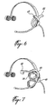
- the two cameras 43 and 52 can be attached together, as seen in figure 6 .
- the two are attached to the headset, one camera facing a direction while the other camera faces the opposite direction.
- the user can choose between a wider view and a narrower view by rotating the dual camera piece by 180 degrees.
- the cameras can be detached from the headset and handled manually, giving the user the freedom of which view to present to the remotely located expert.
- FIG 7 shows yet another alternative embodiment for the headset.
- only one camera 43 is present on the headset, the second camera being worn at the belt (not shown).
- a Liquid Crystal Display (LCD) 68 is also attached to the headset.
- the LCD displays what is being viewed by the camera.
- the image on the LCD 68 seen is the global one.
- the image on the LCD 68 is the detail one.
- the two images may be viewed simultaneously on the LCD 68.
- a picture-in-picture type of display is used, with the detail camera 52 image being displayed in a small corner within the image of the global camera 43 image.
- the LCD 68 is placed at eye level slightly above the camera 43. If desired, the LCD can pivot backwards and be pushed out of the way when not in use (not shown).
- FIG 7 Also seen on figure 7 is an earpiece 70 instead of a big speaker 39 as shown in figure 2 .
- the earpiece 70 is placed around the ear and rests against the head to provide stability to the headset.
- a smaller speaker (not shown) is present on the inner part of the connector 40 for the user to hear any voice communications from the remote expert.
- Figure 8 shows a wireless version of the headset.
- An antenna 72 is present on one side of the headset for receiving and transmitting voice and data signals.
- Batteries 74 are placed inside the headband.
- Digital or analog transmissions for video and audio signals There are two transmission options available: digital or analog transmissions for video and audio signals. Alternatively, a transmission can be done via a cellular phone.
- Figure 9 shows the device that can be used by a person at a remote location to communicate with the user or by the user local in order to provide feedback images of what is being displayed.
- the device flips open to provide a screen wherein the camera images viewed by the user appear. The images are received continuously and are therefore viewed in real time with a minimum amount of delay time.
- a microphone output is provided in the back, along with a video output and an audio output. Therefore, earphones, speakers, microphones, and other types of input and output devices may be connected to the apparatus.
- An AC connector is used to power up the device by connecting it to a power outlet.
- the device may have an infrared port to transmit and receive data via infrared. Alternatively, a battery is used to power up the device.
- the data can be in digital or analog format.
- wireless Local Area Network (LAN) protocols such as 802.11a or 802.11b are used.
- the power pack 32 first converts the analog signal into a digital signal. Then, a compression is done using MPEG 4 (for example).
- the signal is then transmitted using 802.11x and TCP/IP over a LAN, or any communication protocol such as for a cellular phone.
- the streamed data can then be routed onto the LAN to a PC.
- a receiver When using an analog transmission, a receiver is connected to a PC, a monitor, a television, or even a projector.
- the remote expert can view the images via the web.
- the camera on the headset can be a webcam and the data can be transmitted via the internet.
- a website can be dedicated to this purpose.
- the device may also have a USB port to connect itself to a PC, a firewire 1394 port, or any equivalent.
- the images that appear to the remote user may be from the global camera and detail camera simultaneously. This can be done via a picture-in-picture set-up or a split-screen setup. Alternatively, images from one camera are viewed at one time.
- both cameras are color high resolution cameras to provide crisp and focused images.
- the cameras 43 and 52 may have interchangeable lenses.
- the lenses used have focal lengths that can range between 2-25 mm.
- the same lens can be used in both cameras and provide a different effect due to the proximity to the object that is being imaged.
- telepresence equipment is provided 76.
- the equipment comprises a global camera, which can be a video camera or a still camera, a detail camera for close-up views, and an audio link.
- the audio link the communication is to be two way. Therefore, the minimum required is a microphone and a speaker.
- the next step is to mount the global camera on the head of the field user 78.
- the camera can be mounted on the left or right side of the head or on top of the head.
- the camera must move with the field user in the same direction as the head moves.
- the camera is mounted onto a headband placed on the field user's head and is at substantially eye level.
- a power pack is used to power up the camera and a switch turns it on.
- a remote user views the images on the remote display.
- the field user then receives instructions from the remote user on where to point a detail camera 82.
- the field user points the detail camera to specified objects 84 and the images from the detail camera are transmitted to the remote display 86.
- high spatial resolution means the number of pixels per inch on an object.
- the global camera provides a very low spatial resolution for each object viewed while the detail camera provides a high spatial resolution.
- a preferred embodiment comprises using the apparatus described above.
- the global camera sits in a stable manner on the field user's head.
- the field user has a power pack worn at the waist to power the camera and transmit the images wirelessly, or through a long cable, such as a 30 foot cable.
- the power pack also comprises a connector hook to attach the detail camera. Therefore, the field user has his hands free until the detail camera is unhooked from the power pack and pointed to a specific object.
- a light on the detail camera is provided to illuminate the field of view of the detail camera. When the remote user has seen what was asked for, the detail camera is placed back onto its connector hook and the field user can follow instructions from the remote user on how to complete the task at hand.
- the described apparatus may be used by home owners to speak to technical support personnel for help with their computer. It can also be used for guidance to solve electrical or plumbing problems in the home. It can also be used by field workers who need access to experts that are not present in the field, for example working on power towers, in mines, in sewers, etc.
Landscapes
- Engineering & Computer Science (AREA)
- Multimedia (AREA)
- Signal Processing (AREA)
- Studio Devices (AREA)
- Two-Way Televisions, Distribution Of Moving Picture Or The Like (AREA)
- Closed-Circuit Television Systems (AREA)
Abstract
Description
- The invention relates to systems used for telepresence. More specifically, it relates to systems used for remote support from experts to users in the field or at home.
- Many systems already exist for field workers to receive help from an expert remotely located. These systems are not simply cordless headsets, but comprise a camera attached to a headset that allows a remotely located person to view what the user is viewing. The remote person can see what the user is seeing and speak to the user via a speaker. The user can also communicate with the remote person using a microphone.
- These systems have a multitude of applications, ranging from the medical field and the industrial field, to the telecommunications field. Having an expert to consult as if he or she was standing next to you is quite valuable.
- Moreover, these systems could also be used for remote technical support. Users sitting at home and having computer problems could greatly benefit from an apparatus that allows them to contact a person that could see what they are seeing and be able to guide them through solving their problems. The same could be done with electrical problems encountered in the home. A person who can view what.a user is doing can easily guide the user through simple electrical repairs.
- The system can also be used for training. The expert can wear a headset-camera system to demonstrate a procedure to a technician who watches the display.
-
US patent 5,933,479 discloses a remote service system using high tech video links over conventional phone lines, using two-way wireless audio and visual communication in real time, so that technicians at a central site can see exactly what the customer's maintenance person is seeing. This allows an untrained technician or someone unfamiliar with the device to be the eyes, ears and hands of the technician at the central site, so that the maintenance person can be talked through a repair process. For this purpose, the maintenance person wears a headset camera and a microphone. -
WO 00/60868 A1 - However, the existing telepresence systems are bulky and impractical. Because the cameras attached to the headsets are heavy, the apparatus requires an image stabilizing process in order to provide a clear image. An example of this can be seen in
US patent 6,342,915 . - Another disadvantage to the existing telepresence systems is the lack of detail that can be viewed by the remotely located person. The camera that is provided produces an image of the field of view of the user, but without the details. It is more of a global view. However, if the user advances too closely to the target image, then the image is out of focus.
-
WO 01/80212 A WO 01/80212 - In cases such as technical problems that a user is to be guided through, it would be advantageous to have a close-up view in addition to the general view already provided.
- Moreover, since it is essential in a remote support setting to facilitate the communication between the user and a remote helper, there is a need to improve the current telepresence systems such that the remote helper can have access to all the necessary information in order to solve the problems encountered.
- Accordingly, an object of the present invention is to facilitate communication between a field user of telepresence equipment and a remote user.
- Another object of the present invention is to increase the consultation of experts while minimizing the displacements of the experts.
- According to a first broad aspect of the present invention, there is provided a method for telepresence between a field user wearing telepresence equipment and a remote user according to claim 1.
- Preferably, the global camera is a video camera, the detail camera comprises a switch to initiate and stop transmission of close-up images, and the detail camera has a light to illuminate its field of view. The detail camera is attached to a transmitter module using a coil cord or straight cable. The transmitter module is worn at the waist and includes batteries, a transmitter, and connectors for the detail camera and the global camera.
- According to a second broad aspect of the present invention, there is provided an apparatus for telepresence between a field user and a remote user according to claim 14.
- Preferably, the transmission means are comprised in an enclosure attachable to a belt of the field user and the detailed camera is hooked onto the enclosure via a connecting mechanism when not in use. The detailed camera preferably has an activation switch to initiate and terminate the image capture of image close-ups, which are automatically transmitted to the remote display when the detailed camera is in use.
- These and other features, aspects and advantages of the present invention will become better understood with regard to the following description and accompanying drawings wherein:
-
FIG. 1 is a schematic of the portable apparatus; -
FIG. 2 is a view of the headset on a user; -
FIG. 3 is a view of the detachable portion of the headset; -
FIG. 4 is a view of the power pack and detail camera; -
FIG. 5 is a view of the detail camera -
FIG. 6 is an alternative embodiment of the headset; -
FIG. 7 is another alternative embodiment of the headset; -
FIG. 8 is yet another alternative embodiment of the headset; -
FIG. 9 is a view of the remote viewing device; and -
FIG. 10 is a flowchart of the method of the invention. -
Figure 1 depicts the portable apparatus to be worn by a user. It consists of aheadset 30 connected to apower pack 32 that can be worn at the belt. Thepower pack 32 comprises the battery, electronics for transmitting and receiving audio and video signals, video compression electronics, an antenna, and connectors for both cameras. Thepower pack 32 andheadset 30 are linked by acable 33. Alternatively, the connection between the two could be wireless (not shown) and a battery would be integrated into the headset. -
Figure 2 shows the headset portion more clearly. Aheadband 35 is worn around the head to support the apparatus. Once end of the headband is formed of two pad-like support means 37 to enable the headset to remain stable. In the preferred embodiment, the pad-like support means 37 are cushioned on one side to rest against the head of the user and hard on the other side to provide more stability to the headset. Alternatively, any type of support means may be used to allow the headset to reside in a stable manner on a user's head. A second end of the headband covers one of the user's ears. Aspeaker 39 is connected to aconnector portion 40 of the headband and rests on the user's ear. Alternatively, a user can use the speaker of a computer or of a video-conferencing system to receive audio signals. Amicrophone 41 extends outwards from theconnector portion 40 towards the user's mouth. The connectingcable 33 also extends from theconnector portion 40. Afirst camera 43 is attached to the headset on theconnector portion 40. It is at substantially eye level but does not obstruct the user's view. Thecamera 43 is a global camera that captures the perspective view of the user. The headset is adjustable in length via agrooved plastic member 45 into which theheadband 35 is inserted. The headset is always centered in the middle of the ear. As it is based on a human scale, thecamera 43 andmicrophone 41 are automatically leveled properly. -
Figure 3 shows how a portion of the headset is detachable. Theconnector 40,camera 43,microphone 41, andcable 33 can be detached from theheadset 30, leaving behind theheadband 35,speaker 39, and support means 37. Thecamera 43 can then be handled manually, capturing a viewpoint different than the user's viewpoint. The user can manipulate the camera to see images that otherwise would not be accessible. Thecamera 43 andmicrophone 41 are also detachable for transportation purposes. Alternatively, it is possible to detach only thecamera 43 and use it as a hand-held camera while keeping thespeaker 39 andmicrophone 41 attached to theheadset 30. -
Figure 4 shows theportable power pack 32 and asecond camera 52. Thesecond camera 52 is handheld and for viewing details. It is attachable to thepower pack 32 via a connectingpiece 54 on the exterior housing of theprocessor 32. Acoil cord 50 connects thecamera 52 to thepower pack 32. Alternatively, the connection can be wireless. Asmall antenna 56 is also present on thepower pack 32 to transmit the images captured by thefirst camera 43 and thesecond camera 52 wirelessly. Alternatively, thisantenna 56 can be replaced by a wire, wherein thepower pack 32 is connected directly into a system such as a computer. The back of the housing of thepower pack 32 comprises a clip (not shown) to wear the apparatus on a belt or any other type of body harness worn such that thepower pack 32 is positioned ergonomically. - In
figure 5 , thedetail camera 52 is depicted. Aconnector 58 is present in order to attach thecamera 52 to the complementary connectingpiece 54 on the exterior housing of thepower pack 32. Asmall button 60 turns thecamera 52 on or off. Thebutton 60 can be a switch or a slide button. When thebutton 60 is pressed, thecamera 52 is capturing images. When thebutton 60 is released, thecamera 52 is no longer capturing any images and the images transmitted come from theglobal camera 43. Asmall light 62 is present above on thecamera 52 above thelens 64 to illuminate the object being imaged. The light 62 is not always turned on when using thedetail camera 52. In some situations, the light may reflect back into the image and have a negative effect. Alternatively, a laser could be present instead of the light 62 to allow the user to align thecamera 52 properly with its target. Other aligning mechanisms are also possible. Furthermore, thedetail camera 52 may comprise a focusing mechanism, such as a zoom lens. - Alternatively, the two
cameras figure 6 . The two are attached to the headset, one camera facing a direction while the other camera faces the opposite direction. The user can choose between a wider view and a narrower view by rotating the dual camera piece by 180 degrees. The cameras can be detached from the headset and handled manually, giving the user the freedom of which view to present to the remotely located expert. -
Figure 7 shows yet another alternative embodiment for the headset. In this case, only onecamera 43 is present on the headset, the second camera being worn at the belt (not shown). However, a Liquid Crystal Display (LCD) 68 is also attached to the headset. The LCD displays what is being viewed by the camera. When the image is coming from theglobal camera 43, the image on theLCD 68 seen is the global one. When the image is coming from thedetail camera 52, the image on theLCD 68 is the detail one. Alternatively, the two images may be viewed simultaneously on theLCD 68. A picture-in-picture type of display is used, with thedetail camera 52 image being displayed in a small corner within the image of theglobal camera 43 image. TheLCD 68 is placed at eye level slightly above thecamera 43. If desired, the LCD can pivot backwards and be pushed out of the way when not in use (not shown). - Also seen on
figure 7 is anearpiece 70 instead of abig speaker 39 as shown infigure 2 . Theearpiece 70 is placed around the ear and rests against the head to provide stability to the headset. A smaller speaker (not shown) is present on the inner part of theconnector 40 for the user to hear any voice communications from the remote expert. -
Figure 8 shows a wireless version of the headset. Anantenna 72 is present on one side of the headset for receiving and transmitting voice and data signals.Batteries 74 are placed inside the headband. There are two transmission options available: digital or analog transmissions for video and audio signals. Alternatively, a transmission can be done via a cellular phone. -
Figure 9 shows the device that can be used by a person at a remote location to communicate with the user or by the user local in order to provide feedback images of what is being displayed. The device flips open to provide a screen wherein the camera images viewed by the user appear. The images are received continuously and are therefore viewed in real time with a minimum amount of delay time. A microphone output is provided in the back, along with a video output and an audio output. Therefore, earphones, speakers, microphones, and other types of input and output devices may be connected to the apparatus. An AC connector is used to power up the device by connecting it to a power outlet. The device may have an infrared port to transmit and receive data via infrared. Alternatively, a battery is used to power up the device. - Since more than one type of data is being transmitted (voice, images, control signals, etc), two frequency bands may be used. Alternatively, both voice and image information can be sent and received on one frequency band. Also alternatively, images from the
global camera 43 can be sent on one frequency band and images from thedetail camera 52 can be sent on a second frequency band. Voice is then sent on a third frequency. The data can be in digital or analog format. When the data transmitted is in a digital format, wireless Local Area Network (LAN) protocols such as 802.11a or 802.11b are used. In this case, thepower pack 32 first converts the analog signal into a digital signal. Then, a compression is done using MPEG 4 (for example). The signal is then transmitted using 802.11x and TCP/IP over a LAN, or any communication protocol such as for a cellular phone. The streamed data can then be routed onto the LAN to a PC. When using an analog transmission, a receiver is connected to a PC, a monitor, a television, or even a projector. - Alternatively, The remote expert can view the images via the web. The camera on the headset can be a webcam and the data can be transmitted via the internet. A website can be dedicated to this purpose. The device may also have a USB port to connect itself to a PC, a firewire 1394 port, or any equivalent.
- The images that appear to the remote user may be from the global camera and detail camera simultaneously. This can be done via a picture-in-picture set-up or a split-screen setup. Alternatively, images from one camera are viewed at one time.
- Preferably, both cameras are color high resolution cameras to provide crisp and focused images. The
cameras - In
figure 10 , the method for telepresence is illustrated. First, telepresence equipment is provided 76. The equipment comprises a global camera, which can be a video camera or a still camera, a detail camera for close-up views, and an audio link. For the audio link; the communication is to be two way. Therefore, the minimum required is a microphone and a speaker. The next step is to mount the global camera on the head of thefield user 78. The camera can be mounted on the left or right side of the head or on top of the head. The camera must move with the field user in the same direction as the head moves. Preferably, the camera is mounted onto a headband placed on the field user's head and is at substantially eye level. - Once the global camera is on the field user's head, images are to be transmitted from the global camera to a
remote display 80. A power pack is used to power up the camera and a switch turns it on. A remote user views the images on the remote display. The field user then receives instructions from the remote user on where to point adetail camera 82. The field user points the detail camera to specifiedobjects 84 and the images from the detail camera are transmitted to theremote display 86. - By placing the detail camera in very close proximity to an object, a high spatial resolution is obtained. For the purpose of this invention, high spatial resolution means the number of pixels per inch on an object. The global camera provides a very low spatial resolution for each object viewed while the detail camera provides a high spatial resolution.
- A preferred embodiment comprises using the apparatus described above. The global camera sits in a stable manner on the field user's head. The field user has a power pack worn at the waist to power the camera and transmit the images wirelessly, or through a long cable, such as a 30 foot cable. The power pack also comprises a connector hook to attach the detail camera. Therefore, the field user has his hands free until the detail camera is unhooked from the power pack and pointed to a specific object. A light on the detail camera is provided to illuminate the field of view of the detail camera. When the remote user has seen what was asked for, the detail camera is placed back onto its connector hook and the field user can follow instructions from the remote user on how to complete the task at hand.
- It can be appreciated that the described apparatus may be used by home owners to speak to technical support personnel for help with their computer. It can also be used for guidance to solve electrical or plumbing problems in the home. It can also be used by field workers who need access to experts that are not present in the field, for example working on power towers, in mines, in sewers, etc.
Claims (25)
- A method for telepresence between a field user wearing telepresence equipment and a remote user, the method composing:providing said telepresence equipment worn by a field user when in use and including a global camera (43) and a two-way audio link for communication between said field user and said remote user;mounting said global camera (43) and said two-way audio link on the field user's head set (30) to obtain an image of the field user's viewpoint:transmitting images from the global camera (43) to a remote display for said remote user to view;receiving instructions from said remote user through said two-way audio link;characterized by the steps:providing said telepresence equipment with a handheld detail camera (52) for obtaining image close-ups, the handheld detail camera (52) and the global camera (43) being part of a portable telepresence equipment worn by the field user when in use wherein the detail camera (52) is hooked onto the portable apparatus via a connecting mechanism when not in use,receiving instructions from said remote user through said two-way audio link on where to point the detail camera (52) when the remote user instructs the field user via the two-way audio link to point at a certain detail seen by the global camera;pointing said detail camera (52) to specified objects:transmitting images from the detail camera (52) to said remote display for said remote user to view; andmounting a second display (68) to the portable telepresence equipment to view the images being transmitted.
- A method as claimed in claim 1, wherein pointing said detail camera (52) comprises removing said detail camera from a hook, pointing said detail camera to specified objects, and replacing said detail camera on said hook.
- A method as claimed in claims 1 or 2, wherein pointing said detail camera (52) to specified objects comprises pressing a switch on said detail camera to begin transmission of close-up images and releasing said switch to end transmission of said detail images, wherein preferably said pressing a switch turns on a light (62) illuminating a field of view for said detail camera.
- A method as claimed in any one of claims 1 to 3, wherein said providing said telepresence equipment comprises providing an aligning mechanism on said detail camera (52), wherein said providing an aligning mechanism comprises preferably providing a laser to align said detail camera.
- A method as claimed in any one of claims 1 to 4, wherein said providing said telepresence equipment comprises providing a focusing mechanism on said detail camera (52).
- A method as claimed in any one of claims 1 to 5, wherein said transmitting images and said receiving instructions comprises transmitting images and receiving instructions through a wireless network or through the Internet.
- A method as claimed in any one claim 1 to 6, wherein said transmitting images from the global camera (43) to a remote display comprises transmitting said images using a cellular phone.
- A method as claimed in any one of claims 1 to 7, wherein said transmitting images from the global camera (43) and transmitting images from the detail camera (52) comprises transmitting from a same transmitter.
- A method as claimed in claim 8, wherein said transmitting images comprises transmitting audio from said same transmitter.
- A method as claimed in any one of claims 1 to 9, wherein said second display is mounted to said field user's head.
- A method as claimed in any one of claims 1 to 10, wherein said mounting said global camera (43) comprises mounting in a detachable manner such that a global view being displayed may be changed by detaching and moving said global camera.
- A method as claimed in any one of claims 1 to 11, wherein said providing a global camera (43) comprises providing a global video camera.
- A method as claimed in any one of claims 1 to 12, wherein said pointing said detail camera (52) comprises obtaining a high spatial resolution.
- An apparatus for telepresence between a field user and a remote user, the telepresence equipment worn by a field user when in use and comprising:a headset (30) having a two-way audio link for communication between said field user and said remote user:a global camera (43) mounted to said headset (30) for obtaining an image of said field user's viewpoint; andtransmission means for transmitting images from said global camera (43) and said detail camera (52) to a remote display for said remote user to view;characterized in that a handheld detail camera (52) for obtaining image close-ups by said field user is provided. When the remote user instructs the field user via the two-way audio link to point at a certain detail seen by the global camera, the transmission means are provided for transmitting images from said detail camera (52) to a remote display for said remote user to view,wherein the handheld detail camera (52) and the global camera (43) being part of the portable telepresence equipment wherein the detail camera (52) is hooked onto the portable telepresence equipment via connecting mechanism when not in use, and a second display (68) is mounted to said portable telepresence apparatus to view the images being transmitted.
- An apparatus as claimed in claim 14, wherein said handheld detail camera (52) is attachable at a hip of said field user by one of a belt and a body harness.
- An apparatus as claimed in claim 14, wherein said handheld detail camera (52) has an activation switch to initiate image capture of said image close-ups and/or transmission of said images from said detail camera.
- An apparatus as claimed in claim 16, wherein release of said activation switch terminates said image capture of said image close-ups and/or said transmission of said images from said detail camera (52).
- An apparatus as claimed in any one of claims 16 to 17, wherein said activation switch turns on a light (62) illuminating a field of view of said detail camera (52).
- An apparatus as claimed in any one of claims 14 to 18, wherein said handheld detail camera (52) comprises an aligning mechanism, preferably a laser, for targeting an object to be captured in said image close-ups.
- An apparatus as claimed in any one of claims 16 to 19, wherein said handheld detail camera (52) has a focusing mechanism.
- An apparatus as claimed in claim 14, wherein said transmission means comprises means for transmitting through a wireless network to allow a field user freedom to move around without a wired connection to a fixed transmission station and/or means for transmitting through the internet to allow a field user to connect and transmit using a personal computer and/or a single transmitter to transmit images from said global camera and said handheld detail camera.
- An apparatus as claimed in claim 21, wherein said single transmitter also transmits audio signals.
- An apparatus as claimed in claim 14, wherein said second display is mounted to said headset (30).
- An apparatus as claimed in claim 14, wherein said global camera (43) is detachable from said headset (30).
- An apparatus as claimed in claim 14, wherein said transmitting means are comprised in a portable enclosure attachable at a hip of said field user and said detail camera (52) and headset (30) are connected to said portable enclosure via a wired connection.
Applications Claiming Priority (3)
| Application Number | Priority Date | Filing Date | Title |
|---|---|---|---|
| US232418 | 2002-09-03 | ||
| US10/232,418 US6753899B2 (en) | 2002-09-03 | 2002-09-03 | Method and apparatus for telepresence |
| PCT/CA2003/001282 WO2004023816A1 (en) | 2002-09-03 | 2003-08-29 | Method and apparatus for telepresence |
Publications (2)
| Publication Number | Publication Date |
|---|---|
| EP1552697A1 EP1552697A1 (en) | 2005-07-13 |
| EP1552697B1 true EP1552697B1 (en) | 2011-07-20 |
Family
ID=31977000
Family Applications (1)
| Application Number | Title | Priority Date | Filing Date |
|---|---|---|---|
| EP03793516A Expired - Lifetime EP1552697B1 (en) | 2002-09-03 | 2003-08-29 | Method and apparatus for telepresence |
Country Status (6)
| Country | Link |
|---|---|
| US (1) | US6753899B2 (en) |
| EP (1) | EP1552697B1 (en) |
| AT (1) | ATE517383T1 (en) |
| AU (1) | AU2003258429A1 (en) |
| CA (1) | CA2538943C (en) |
| WO (1) | WO2004023816A1 (en) |
Cited By (1)
| Publication number | Priority date | Publication date | Assignee | Title |
|---|---|---|---|---|
| WO2018136072A1 (en) * | 2017-01-19 | 2018-07-26 | Hewlett-Packard Development Company, L.P. | Telepresence |
Families Citing this family (148)
| Publication number | Priority date | Publication date | Assignee | Title |
|---|---|---|---|---|
| US7224962B1 (en) | 1997-10-03 | 2007-05-29 | Karen Jeanne Kite | Remote operational screener |
| US20040162637A1 (en) | 2002-07-25 | 2004-08-19 | Yulun Wang | Medical tele-robotic system with a master remote station with an arbitrator |
| US6925357B2 (en) * | 2002-07-25 | 2005-08-02 | Intouch Health, Inc. | Medical tele-robotic system |
| US7631261B2 (en) * | 2002-09-12 | 2009-12-08 | Inoue Technologies, LLC | Efficient method for creating a visual telepresence for large numbers of simultaneous users |
| TWI276357B (en) * | 2002-09-17 | 2007-03-11 | Ginganet Corp | Image input apparatus for sign language talk, image input/output apparatus for sign language talk, and system for sign language translation |
| US8154581B2 (en) | 2002-10-15 | 2012-04-10 | Revolutionary Concepts, Inc. | Audio-video communication system for receiving person at entrance |
| US7538745B2 (en) * | 2003-03-24 | 2009-05-26 | Ntag Interactive Corporation | Apparatus and method for enhancing face-to-face communication |
| EP2148504B1 (en) * | 2003-12-03 | 2012-01-25 | Nikon Corporation | Information Display Device |
| US7813836B2 (en) | 2003-12-09 | 2010-10-12 | Intouch Technologies, Inc. | Protocol for a remotely controlled videoconferencing robot |
| US9236043B2 (en) * | 2004-04-02 | 2016-01-12 | Knfb Reader, Llc | Document mode processing for portable reading machine enabling document navigation |
| DE102004019989B3 (en) * | 2004-04-23 | 2005-12-15 | Siemens Ag | Arrangement and method for carrying out videoconferencing |
| US20050278446A1 (en) * | 2004-05-27 | 2005-12-15 | Jeffery Bryant | Home improvement telepresence system and method |
| US8077963B2 (en) | 2004-07-13 | 2011-12-13 | Yulun Wang | Mobile robot with a head-based movement mapping scheme |
| US20060052676A1 (en) * | 2004-09-07 | 2006-03-09 | Yulun Wang | Tele-presence system that allows for remote monitoring/observation and review of a patient and their medical records |
| US20060080431A1 (en) * | 2004-10-12 | 2006-04-13 | Cheng-Hsien Chao | MP3 headphone structure |
| US20060195354A1 (en) * | 2005-02-28 | 2006-08-31 | Ntag Interactive Corporation | Method of scoring the performance of attendees at a meeting |
| US9198728B2 (en) * | 2005-09-30 | 2015-12-01 | Intouch Technologies, Inc. | Multi-camera mobile teleconferencing platform |
| US7697827B2 (en) | 2005-10-17 | 2010-04-13 | Konicek Jeffrey C | User-friendlier interfaces for a camera |
| US20070198324A1 (en) * | 2006-02-22 | 2007-08-23 | Borovoy Richard D | Enabling connections between and events attended by people |
| US20070236334A1 (en) * | 2006-03-31 | 2007-10-11 | Borovoy Richard D | Enhancing face-to-face communication |
| US8004555B2 (en) | 2006-05-31 | 2011-08-23 | Motorola Mobility, Inc. | Methods and devices for simultaneous dual camera video telephony |
| JP2009540298A (en) * | 2006-06-05 | 2009-11-19 | ヴィジコン インスペクション テクノロジーズ エルエルシー | Stent inspection system |
| US8849679B2 (en) * | 2006-06-15 | 2014-09-30 | Intouch Technologies, Inc. | Remote controlled robot system that provides medical images |
| JP5119636B2 (en) * | 2006-09-27 | 2013-01-16 | ソニー株式会社 | Display device and display method |
| US7583191B2 (en) | 2006-11-14 | 2009-09-01 | Zinser Duke W | Security system and method for use of same |
| US8633960B2 (en) * | 2007-02-20 | 2014-01-21 | St-Ericsson Sa | Communication device for processing person associated pictures and video streams |
| US8265793B2 (en) | 2007-03-20 | 2012-09-11 | Irobot Corporation | Mobile robot for telecommunication |
| US9160783B2 (en) | 2007-05-09 | 2015-10-13 | Intouch Technologies, Inc. | Robot system that operates through a network firewall |
| US8208024B2 (en) * | 2007-11-30 | 2012-06-26 | Target Brands, Inc. | Communication and surveillance system |
| US10875182B2 (en) | 2008-03-20 | 2020-12-29 | Teladoc Health, Inc. | Remote presence system mounted to operating room hardware |
| US8179418B2 (en) | 2008-04-14 | 2012-05-15 | Intouch Technologies, Inc. | Robotic based health care system |
| US8170241B2 (en) | 2008-04-17 | 2012-05-01 | Intouch Technologies, Inc. | Mobile tele-presence system with a microphone system |
| US20090262205A1 (en) * | 2008-04-21 | 2009-10-22 | Dana Stephen Smith | Voice activated headset imaging system |
| US9193065B2 (en) | 2008-07-10 | 2015-11-24 | Intouch Technologies, Inc. | Docking system for a tele-presence robot |
| US9842192B2 (en) | 2008-07-11 | 2017-12-12 | Intouch Technologies, Inc. | Tele-presence robot system with multi-cast features |
| US20100066802A1 (en) * | 2008-09-16 | 2010-03-18 | Brian Dross | Remote communications device and method for facilitating manual operations |
| US8340819B2 (en) | 2008-09-18 | 2012-12-25 | Intouch Technologies, Inc. | Mobile videoconferencing robot system with network adaptive driving |
| US8996165B2 (en) | 2008-10-21 | 2015-03-31 | Intouch Technologies, Inc. | Telepresence robot with a camera boom |
| US8463435B2 (en) | 2008-11-25 | 2013-06-11 | Intouch Technologies, Inc. | Server connectivity control for tele-presence robot |
| US9138891B2 (en) * | 2008-11-25 | 2015-09-22 | Intouch Technologies, Inc. | Server connectivity control for tele-presence robot |
| US8849680B2 (en) | 2009-01-29 | 2014-09-30 | Intouch Technologies, Inc. | Documentation through a remote presence robot |
| US8897920B2 (en) | 2009-04-17 | 2014-11-25 | Intouch Technologies, Inc. | Tele-presence robot system with software modularity, projector and laser pointer |
| US20100321465A1 (en) * | 2009-06-19 | 2010-12-23 | Dominique A Behrens Pa | Method, System and Computer Program Product for Mobile Telepresence Interactions |
| US8384755B2 (en) * | 2009-08-26 | 2013-02-26 | Intouch Technologies, Inc. | Portable remote presence robot |
| JP2013503571A (en) * | 2009-08-26 | 2013-01-31 | インタッチ・テクノロジーズ・インコーポレーテッド | Portable telepresence device |
| US11399153B2 (en) * | 2009-08-26 | 2022-07-26 | Teladoc Health, Inc. | Portable telepresence apparatus |
| US11154981B2 (en) * | 2010-02-04 | 2021-10-26 | Teladoc Health, Inc. | Robot user interface for telepresence robot system |
| US20110187875A1 (en) * | 2010-02-04 | 2011-08-04 | Intouch Technologies, Inc. | Robot face used in a sterile environment |
| US8670017B2 (en) | 2010-03-04 | 2014-03-11 | Intouch Technologies, Inc. | Remote presence system including a cart that supports a robot face and an overhead camera |
| US9014848B2 (en) | 2010-05-20 | 2015-04-21 | Irobot Corporation | Mobile robot system |
| US8935005B2 (en) | 2010-05-20 | 2015-01-13 | Irobot Corporation | Operating a mobile robot |
| US8918213B2 (en) | 2010-05-20 | 2014-12-23 | Irobot Corporation | Mobile human interface robot |
| US10343283B2 (en) | 2010-05-24 | 2019-07-09 | Intouch Technologies, Inc. | Telepresence robot system that can be accessed by a cellular phone |
| US10808882B2 (en) | 2010-05-26 | 2020-10-20 | Intouch Technologies, Inc. | Tele-robotic system with a robot face placed on a chair |
| US8717447B2 (en) | 2010-08-20 | 2014-05-06 | Gary Stephen Shuster | Remote telepresence gaze direction |
| US9264664B2 (en) | 2010-12-03 | 2016-02-16 | Intouch Technologies, Inc. | Systems and methods for dynamic bandwidth allocation |
| US8930019B2 (en) | 2010-12-30 | 2015-01-06 | Irobot Corporation | Mobile human interface robot |
| US20120196254A1 (en) * | 2011-01-27 | 2012-08-02 | Bobby Joe Marsh | Methods and systems for concurrent teaching of assembly processes at disparate locations |
| EP2668008A4 (en) | 2011-01-28 | 2018-01-24 | Intouch Technologies, Inc. | Interfacing with a mobile telepresence robot |
| US9323250B2 (en) | 2011-01-28 | 2016-04-26 | Intouch Technologies, Inc. | Time-dependent navigation of telepresence robots |
| US10769739B2 (en) | 2011-04-25 | 2020-09-08 | Intouch Technologies, Inc. | Systems and methods for management of information among medical providers and facilities |
| US20140139616A1 (en) | 2012-01-27 | 2014-05-22 | Intouch Technologies, Inc. | Enhanced Diagnostics for a Telepresence Robot |
| US9098611B2 (en) | 2012-11-26 | 2015-08-04 | Intouch Technologies, Inc. | Enhanced video interaction for a user interface of a telepresence network |
| US8836751B2 (en) | 2011-11-08 | 2014-09-16 | Intouch Technologies, Inc. | Tele-presence system with a user interface that displays different communication links |
| US8902278B2 (en) | 2012-04-11 | 2014-12-02 | Intouch Technologies, Inc. | Systems and methods for visualizing and managing telepresence devices in healthcare networks |
| US9251313B2 (en) | 2012-04-11 | 2016-02-02 | Intouch Technologies, Inc. | Systems and methods for visualizing and managing telepresence devices in healthcare networks |
| US9361021B2 (en) | 2012-05-22 | 2016-06-07 | Irobot Corporation | Graphical user interfaces including touchpad driving interfaces for telemedicine devices |
| WO2013176758A1 (en) | 2012-05-22 | 2013-11-28 | Intouch Technologies, Inc. | Clinical workflows utilizing autonomous and semi-autonomous telemedicine devices |
| DE102012110761B4 (en) | 2012-11-09 | 2017-09-21 | Vodafone Holding Gmbh | Telepresence system and method for coordinating and / or handling actions at a remote location by means of a teleoperator |
| CN105027206A (en) * | 2012-11-29 | 2015-11-04 | 斯蒂芬·蔡斯 | Video headphones, system, platform, methods, apparatuses and media |
| US10061349B2 (en) * | 2012-12-06 | 2018-08-28 | Sandisk Technologies Llc | Head mountable camera system |
| US10110805B2 (en) | 2012-12-06 | 2018-10-23 | Sandisk Technologies Llc | Head mountable camera system |
| US20150172607A1 (en) | 2013-03-14 | 2015-06-18 | Google Inc. | Providing vicarious tourism sessions |
| US20150015707A1 (en) * | 2013-07-10 | 2015-01-15 | Subc Control Limited | Telepresence method and system for tracking head movement of a user |
| US9609290B2 (en) * | 2013-07-10 | 2017-03-28 | Subc Control Limited | Telepresence method and system for supporting out of range motion by aligning remote camera with user's head |
| US10672238B2 (en) | 2015-06-23 | 2020-06-02 | SkyBell Technologies, Inc. | Doorbell communities |
| US10733823B2 (en) | 2013-07-26 | 2020-08-04 | Skybell Technologies Ip, Llc | Garage door communication systems and methods |
| US10708404B2 (en) | 2014-09-01 | 2020-07-07 | Skybell Technologies Ip, Llc | Doorbell communication and electrical systems |
| US10440165B2 (en) | 2013-07-26 | 2019-10-08 | SkyBell Technologies, Inc. | Doorbell communication and electrical systems |
| US9179107B1 (en) | 2013-07-26 | 2015-11-03 | SkyBell Technologies, Inc. | Doorbell chime systems and methods |
| US9053622B2 (en) | 2013-07-26 | 2015-06-09 | Joseph Frank Scalisi | Light socket cameras |
| US9237318B2 (en) | 2013-07-26 | 2016-01-12 | SkyBell Technologies, Inc. | Doorbell communication systems and methods |
| US10204467B2 (en) | 2013-07-26 | 2019-02-12 | SkyBell Technologies, Inc. | Smart lock systems and methods |
| US9736284B2 (en) | 2013-07-26 | 2017-08-15 | SkyBell Technologies, Inc. | Doorbell communication and electrical systems |
| US9230424B1 (en) | 2013-12-06 | 2016-01-05 | SkyBell Technologies, Inc. | Doorbell communities |
| US9142214B2 (en) | 2013-07-26 | 2015-09-22 | SkyBell Technologies, Inc. | Light socket cameras |
| US11004312B2 (en) | 2015-06-23 | 2021-05-11 | Skybell Technologies Ip, Llc | Doorbell communities |
| US9196133B2 (en) | 2013-07-26 | 2015-11-24 | SkyBell Technologies, Inc. | Doorbell communication systems and methods |
| US9247219B2 (en) | 2013-07-26 | 2016-01-26 | SkyBell Technologies, Inc. | Doorbell communication systems and methods |
| US9160987B1 (en) | 2013-07-26 | 2015-10-13 | SkyBell Technologies, Inc. | Doorbell chime systems and methods |
| US9235943B2 (en) | 2013-07-26 | 2016-01-12 | Joseph Frank Scalisi | Remote identity verification of lodging guests |
| US9113052B1 (en) | 2013-07-26 | 2015-08-18 | SkyBell Technologies, Inc. | Doorbell communication systems and methods |
| US9013575B2 (en) | 2013-07-26 | 2015-04-21 | SkyBell Technologies, Inc. | Doorbell communication systems and methods |
| US9179109B1 (en) | 2013-12-06 | 2015-11-03 | SkyBell Technologies, Inc. | Doorbell communication systems and methods |
| US9065987B2 (en) | 2013-07-26 | 2015-06-23 | SkyBell Technologies, Inc. | Doorbell communication systems and methods |
| US9060103B2 (en) | 2013-07-26 | 2015-06-16 | SkyBell Technologies, Inc. | Doorbell security and safety |
| US20170263067A1 (en) | 2014-08-27 | 2017-09-14 | SkyBell Technologies, Inc. | Smart lock systems and methods |
| US9058738B1 (en) | 2013-07-26 | 2015-06-16 | SkyBell Technologies, Inc. | Doorbell communication systems and methods |
| US9060104B2 (en) | 2013-07-26 | 2015-06-16 | SkyBell Technologies, Inc. | Doorbell communication systems and methods |
| US8937659B1 (en) | 2013-07-26 | 2015-01-20 | SkyBell Technologies, Inc. | Doorbell communication and electrical methods |
| US11889009B2 (en) | 2013-07-26 | 2024-01-30 | Skybell Technologies Ip, Llc | Doorbell communication and electrical systems |
| US9113051B1 (en) | 2013-07-26 | 2015-08-18 | SkyBell Technologies, Inc. | Power outlet cameras |
| US9165444B2 (en) | 2013-07-26 | 2015-10-20 | SkyBell Technologies, Inc. | Light socket cameras |
| US9179108B1 (en) | 2013-07-26 | 2015-11-03 | SkyBell Technologies, Inc. | Doorbell chime systems and methods |
| US9172920B1 (en) | 2014-09-01 | 2015-10-27 | SkyBell Technologies, Inc. | Doorbell diagnostics |
| US8947530B1 (en) | 2013-07-26 | 2015-02-03 | Joseph Frank Scalisi | Smart lock systems and methods |
| US9342936B2 (en) | 2013-07-26 | 2016-05-17 | SkyBell Technologies, Inc. | Smart lock systems and methods |
| US8780201B1 (en) | 2013-07-26 | 2014-07-15 | SkyBell Technologies, Inc. | Doorbell communication systems and methods |
| US11651665B2 (en) | 2013-07-26 | 2023-05-16 | Skybell Technologies Ip, Llc | Doorbell communities |
| US8941736B1 (en) | 2013-07-26 | 2015-01-27 | SkyBell Technologies, Inc. | Doorbell communication systems and methods |
| US9094584B2 (en) | 2013-07-26 | 2015-07-28 | SkyBell Technologies, Inc. | Doorbell communication systems and methods |
| US9172921B1 (en) | 2013-12-06 | 2015-10-27 | SkyBell Technologies, Inc. | Doorbell antenna |
| US9049352B2 (en) | 2013-07-26 | 2015-06-02 | SkyBell Technologies, Inc. | Pool monitor systems and methods |
| US8872915B1 (en) | 2013-07-26 | 2014-10-28 | SkyBell Technologies, Inc. | Doorbell communication systems and methods |
| US8953040B1 (en) | 2013-07-26 | 2015-02-10 | SkyBell Technologies, Inc. | Doorbell communication and electrical systems |
| US9769435B2 (en) | 2014-08-11 | 2017-09-19 | SkyBell Technologies, Inc. | Monitoring systems and methods |
| US10044519B2 (en) | 2015-01-05 | 2018-08-07 | SkyBell Technologies, Inc. | Doorbell communication systems and methods |
| US9118819B1 (en) | 2013-07-26 | 2015-08-25 | SkyBell Technologies, Inc. | Doorbell communication systems and methods |
| US9197867B1 (en) | 2013-12-06 | 2015-11-24 | SkyBell Technologies, Inc. | Identity verification using a social network |
| US9172922B1 (en) | 2013-12-06 | 2015-10-27 | SkyBell Technologies, Inc. | Doorbell communication systems and methods |
| US20180343141A1 (en) | 2015-09-22 | 2018-11-29 | SkyBell Technologies, Inc. | Doorbell communication systems and methods |
| USD747733S1 (en) | 2013-08-30 | 2016-01-19 | SkyBell Technologies, Inc. | Display screen or portion thereof with a graphical user interface |
| USD747732S1 (en) | 2013-08-30 | 2016-01-19 | SkyBell Technologies, Inc. | Display screen or portion thereof with a graphical user interface |
| USD737283S1 (en) | 2013-08-30 | 2015-08-25 | SkyBell Technologies, Inc. | Display screen or portion thereof with a graphical user interface |
| US9786133B2 (en) | 2013-12-06 | 2017-10-10 | SkyBell Technologies, Inc. | Doorbell chime systems and methods |
| US9743049B2 (en) | 2013-12-06 | 2017-08-22 | SkyBell Technologies, Inc. | Doorbell communication systems and methods |
| US9253455B1 (en) | 2014-06-25 | 2016-02-02 | SkyBell Technologies, Inc. | Doorbell communication systems and methods |
| US9799183B2 (en) | 2013-12-06 | 2017-10-24 | SkyBell Technologies, Inc. | Doorbell package detection systems and methods |
| USD731573S1 (en) | 2014-03-13 | 2015-06-09 | Cisco Technology, Inc. | Camera system |
| USD762688S1 (en) | 2014-05-16 | 2016-08-02 | SkyBell Technologies, Inc. | Display screen or a portion thereof with a graphical user interface |
| US20170085843A1 (en) | 2015-09-22 | 2017-03-23 | SkyBell Technologies, Inc. | Doorbell communication systems and methods |
| US11184589B2 (en) | 2014-06-23 | 2021-11-23 | Skybell Technologies Ip, Llc | Doorbell communication systems and methods |
| US9888216B2 (en) | 2015-09-22 | 2018-02-06 | SkyBell Technologies, Inc. | Doorbell communication systems and methods |
| US10687029B2 (en) | 2015-09-22 | 2020-06-16 | SkyBell Technologies, Inc. | Doorbell communication systems and methods |
| US9997036B2 (en) | 2015-02-17 | 2018-06-12 | SkyBell Technologies, Inc. | Power outlet cameras |
| US10742938B2 (en) | 2015-03-07 | 2020-08-11 | Skybell Technologies Ip, Llc | Garage door communication systems and methods |
| US11575537B2 (en) | 2015-03-27 | 2023-02-07 | Skybell Technologies Ip, Llc | Doorbell communication systems and methods |
| US11381686B2 (en) | 2015-04-13 | 2022-07-05 | Skybell Technologies Ip, Llc | Power outlet cameras |
| US20180047269A1 (en) | 2015-06-23 | 2018-02-15 | SkyBell Technologies, Inc. | Doorbell communities |
| US10706702B2 (en) | 2015-07-30 | 2020-07-07 | Skybell Technologies Ip, Llc | Doorbell package detection systems and methods |
| US10043332B2 (en) | 2016-05-27 | 2018-08-07 | SkyBell Technologies, Inc. | Doorbell package detection systems and methods |
| US11862302B2 (en) | 2017-04-24 | 2024-01-02 | Teladoc Health, Inc. | Automated transcription and documentation of tele-health encounters |
| US10483007B2 (en) | 2017-07-25 | 2019-11-19 | Intouch Technologies, Inc. | Modular telehealth cart with thermal imaging and touch screen user interface |
| US11636944B2 (en) | 2017-08-25 | 2023-04-25 | Teladoc Health, Inc. | Connectivity infrastructure for a telehealth platform |
| US10909825B2 (en) | 2017-09-18 | 2021-02-02 | Skybell Technologies Ip, Llc | Outdoor security systems and methods |
| US10617299B2 (en) | 2018-04-27 | 2020-04-14 | Intouch Technologies, Inc. | Telehealth cart that supports a removable tablet with seamless audio/video switching |
| IT201900001711A1 (en) * | 2019-02-06 | 2020-08-06 | Savoia S R L | SYSTEM AND METHOD OF DIGITAL INTERACTION BETWEEN USERS FOR THE OPTIMIZATION OF PHYSICAL MOVEMENTS |
| WO2021041354A1 (en) | 2019-08-24 | 2021-03-04 | Skybell Technologies Ip, Llc | Doorbell communication systems and methods |
Citations (3)
| Publication number | Priority date | Publication date | Assignee | Title |
|---|---|---|---|---|
| GB2285361A (en) * | 1993-12-28 | 1995-07-05 | Mitsubishi Electric Corp | Video transmission apparatus for video teleconference terminal |
| EP0714081A1 (en) * | 1994-11-22 | 1996-05-29 | Sensormatic Electronics Corporation | Video surveillance system |
| WO2000060868A1 (en) * | 1999-04-05 | 2000-10-12 | Bechtel Bwxt Idaho, Llc | Systems and methods for improved telepresence |
Family Cites Families (17)
| Publication number | Priority date | Publication date | Assignee | Title |
|---|---|---|---|---|
| US5973728A (en) | 1994-05-09 | 1999-10-26 | Airway Cam Technologies, Inc. | Direct laryngoscopy video system |
| US5850250A (en) | 1994-07-18 | 1998-12-15 | Bell Atlantic Maryland, Inc. | Video distance learning system |
| WO1996014641A1 (en) | 1994-11-04 | 1996-05-17 | Kelly Shawn L | Modular binocular electronic imaging system |
| JPH11501572A (en) | 1995-04-10 | 1999-02-09 | ユナイテッド パーセル サービス オブ アメリカ,インコーポレイテッド | Two-camera system that detects and stores the position of an index on a conveyed article |
| US5879289A (en) | 1996-07-15 | 1999-03-09 | Universal Technologies International, Inc. | Hand-held portable endoscopic camera |
| US6046712A (en) | 1996-07-23 | 2000-04-04 | Telxon Corporation | Head mounted communication system for providing interactive visual communications with a remote system |
| USH1790H (en) * | 1996-11-21 | 1999-03-02 | The United States Of America As Represented By The Secretary Of The Army | Medic-cam |
| US5886735A (en) * | 1997-01-14 | 1999-03-23 | Bullister; Edward T | Video telephone headset |
| US6303488B1 (en) | 1997-02-12 | 2001-10-16 | Micron Technology, Inc. | Semiconductor processing methods of forming openings to devices and substrates, exposing material from which photoresist cannot be substantially selectively removed |
| JP3217723B2 (en) * | 1997-03-13 | 2001-10-15 | ▲すすむ▼ 舘 | Telecommunications system and telecommunications method |
| US6028627A (en) | 1997-06-04 | 2000-02-22 | Helmsderfer; John A. | Camera system for capturing a sporting activity from the perspective of the participant |
| CA2310114A1 (en) | 1998-02-02 | 1999-08-02 | Steve Mann | Wearable camera system with viewfinder means |
| US6317039B1 (en) * | 1998-10-19 | 2001-11-13 | John A. Thomason | Wireless video audio data remote system |
| US5933479A (en) * | 1998-10-22 | 1999-08-03 | Toyoda Machinery Usa Corp. | Remote service system |
| US20020030637A1 (en) | 1998-10-29 | 2002-03-14 | Mann W. Stephen G. | Aremac-based means and apparatus for interaction with computer, or one or more other people, through a camera |
| GB0007029D0 (en) | 2000-03-24 | 2000-05-10 | Sumerian Guard Limited | Audio visual headgear |
| AU2001253345A1 (en) | 2000-04-12 | 2001-10-30 | T3D, Inc. | Interactive video device and method of use |
-
2002
- 2002-09-03 US US10/232,418 patent/US6753899B2/en not_active Expired - Fee Related
-
2003
- 2003-08-29 AU AU2003258429A patent/AU2003258429A1/en not_active Abandoned
- 2003-08-29 CA CA2538943A patent/CA2538943C/en not_active Expired - Fee Related
- 2003-08-29 EP EP03793516A patent/EP1552697B1/en not_active Expired - Lifetime
- 2003-08-29 WO PCT/CA2003/001282 patent/WO2004023816A1/en not_active Application Discontinuation
- 2003-08-29 AT AT03793516T patent/ATE517383T1/en not_active IP Right Cessation
Patent Citations (3)
| Publication number | Priority date | Publication date | Assignee | Title |
|---|---|---|---|---|
| GB2285361A (en) * | 1993-12-28 | 1995-07-05 | Mitsubishi Electric Corp | Video transmission apparatus for video teleconference terminal |
| EP0714081A1 (en) * | 1994-11-22 | 1996-05-29 | Sensormatic Electronics Corporation | Video surveillance system |
| WO2000060868A1 (en) * | 1999-04-05 | 2000-10-12 | Bechtel Bwxt Idaho, Llc | Systems and methods for improved telepresence |
Cited By (1)
| Publication number | Priority date | Publication date | Assignee | Title |
|---|---|---|---|---|
| WO2018136072A1 (en) * | 2017-01-19 | 2018-07-26 | Hewlett-Packard Development Company, L.P. | Telepresence |
Also Published As
| Publication number | Publication date |
|---|---|
| US20040041904A1 (en) | 2004-03-04 |
| WO2004023816A1 (en) | 2004-03-18 |
| US6753899B2 (en) | 2004-06-22 |
| EP1552697A1 (en) | 2005-07-13 |
| ATE517383T1 (en) | 2011-08-15 |
| CA2538943C (en) | 2013-12-24 |
| AU2003258429A1 (en) | 2004-03-29 |
| CA2538943A1 (en) | 2004-03-18 |
Similar Documents
| Publication | Publication Date | Title |
|---|---|---|
| EP1552697B1 (en) | Method and apparatus for telepresence | |
| US20050174434A1 (en) | Camera lens interface device | |
| CN104756093B (en) | For mobile or network equipment interchangeable wireless sensing device | |
| US20080266448A1 (en) | Wearable personal video/audio device method and system | |
| US20060052684A1 (en) | Medical cockpit system | |
| US20090247833A1 (en) | Adapter for removably coupling a camera to a laryngoscope and laryngoscope and system using same | |
| WO2003053057A1 (en) | Camera positioning system and method for eye-to-eye communication | |
| US10462428B1 (en) | Video system and method for allowing users, including medical professionals, to capture video of relevant activities and procedures | |
| CA3001375A1 (en) | Methods and systems for wireless live video streaming from a welding helmet | |
| US7365766B1 (en) | Video-assisted apparatus for hearing impaired persons | |
| JP2001326845A (en) | Electronic camera system | |
| JPH05211650A (en) | Duplex information transmitting system | |
| KR20070113067A (en) | Portable stereo vision camera | |
| WO2019119022A1 (en) | Augmented visual assistance system for assisting a person working at a remote workplace, method and headwear for use therewith | |
| US20100066802A1 (en) | Remote communications device and method for facilitating manual operations | |
| JP2011223310A (en) | Image capturing apparatus | |
| JP2005303683A (en) | Image transceiver | |
| EP0986803B1 (en) | Video-assisted apparatus for hearing impaired persons | |
| WO2019116159A1 (en) | Shockproof helmet for remote assistance | |
| TWI691781B (en) | Interactive earphone with camera | |
| JP2004096661A (en) | Camera apparatus | |
| JPH04208995A (en) | Visual information transmitting device | |
| EP3851020A1 (en) | Digital magnifying device | |
| KR200198302Y1 (en) | Picture handphone being able to separate and installate the camera for picture to headphone | |
| JP2000312356A (en) | System for guiding visually handicapped person |
Legal Events
| Date | Code | Title | Description |
|---|---|---|---|
| PUAI | Public reference made under article 153(3) epc to a published international application that has entered the european phase |
Free format text: ORIGINAL CODE: 0009012 |
|
| 17P | Request for examination filed |
Effective date: 20050402 |
|
| AK | Designated contracting states |
Kind code of ref document: A1 Designated state(s): AT BE BG CH CY CZ DE DK EE ES FI FR GB GR HU IE IT LI LU MC NL PT RO SE SI SK TR |
|
| AX | Request for extension of the european patent |
Extension state: AL LT LV MK |
|
| DAX | Request for extension of the european patent (deleted) | ||
| 17Q | First examination report despatched |
Effective date: 20071023 |
|
| GRAP | Despatch of communication of intention to grant a patent |
Free format text: ORIGINAL CODE: EPIDOSNIGR1 |
|
| RIC1 | Information provided on ipc code assigned before grant |
Ipc: H04N 5/232 20060101ALI20101025BHEP Ipc: H04N 5/225 20060101ALI20101025BHEP Ipc: G06F 1/16 20060101AFI20101025BHEP Ipc: H04N 7/18 20060101ALI20101025BHEP |
|
| GRAS | Grant fee paid |
Free format text: ORIGINAL CODE: EPIDOSNIGR3 |
|
| GRAA | (expected) grant |
Free format text: ORIGINAL CODE: 0009210 |
|
| AK | Designated contracting states |
Kind code of ref document: B1 Designated state(s): AT BE BG CH CY CZ DE DK EE ES FI FR GB GR HU IE IT LI LU MC NL PT RO SE SI SK TR |
|
| REG | Reference to a national code |
Ref country code: GB Ref legal event code: FG4D |
|
| REG | Reference to a national code |
Ref country code: CH Ref legal event code: EP |
|
| REG | Reference to a national code |
Ref country code: DE Ref legal event code: R096 Ref document number: 60337759 Country of ref document: DE Effective date: 20110908 |
|
| REG | Reference to a national code |
Ref country code: NL Ref legal event code: VDEP Effective date: 20110720 |
|
| REG | Reference to a national code |
Ref country code: AT Ref legal event code: MK05 Ref document number: 517383 Country of ref document: AT Kind code of ref document: T Effective date: 20110720 |
|
| PG25 | Lapsed in a contracting state [announced via postgrant information from national office to epo] |
Ref country code: BE Free format text: LAPSE BECAUSE OF FAILURE TO SUBMIT A TRANSLATION OF THE DESCRIPTION OR TO PAY THE FEE WITHIN THE PRESCRIBED TIME-LIMIT Effective date: 20110720 Ref country code: FI Free format text: LAPSE BECAUSE OF FAILURE TO SUBMIT A TRANSLATION OF THE DESCRIPTION OR TO PAY THE FEE WITHIN THE PRESCRIBED TIME-LIMIT Effective date: 20110720 Ref country code: PT Free format text: LAPSE BECAUSE OF FAILURE TO SUBMIT A TRANSLATION OF THE DESCRIPTION OR TO PAY THE FEE WITHIN THE PRESCRIBED TIME-LIMIT Effective date: 20111121 Ref country code: SE Free format text: LAPSE BECAUSE OF FAILURE TO SUBMIT A TRANSLATION OF THE DESCRIPTION OR TO PAY THE FEE WITHIN THE PRESCRIBED TIME-LIMIT Effective date: 20110720 Ref country code: NL Free format text: LAPSE BECAUSE OF FAILURE TO SUBMIT A TRANSLATION OF THE DESCRIPTION OR TO PAY THE FEE WITHIN THE PRESCRIBED TIME-LIMIT Effective date: 20110720 |
|
| PG25 | Lapsed in a contracting state [announced via postgrant information from national office to epo] |
Ref country code: GR Free format text: LAPSE BECAUSE OF FAILURE TO SUBMIT A TRANSLATION OF THE DESCRIPTION OR TO PAY THE FEE WITHIN THE PRESCRIBED TIME-LIMIT Effective date: 20111021 Ref country code: AT Free format text: LAPSE BECAUSE OF FAILURE TO SUBMIT A TRANSLATION OF THE DESCRIPTION OR TO PAY THE FEE WITHIN THE PRESCRIBED TIME-LIMIT Effective date: 20110720 Ref country code: SI Free format text: LAPSE BECAUSE OF FAILURE TO SUBMIT A TRANSLATION OF THE DESCRIPTION OR TO PAY THE FEE WITHIN THE PRESCRIBED TIME-LIMIT Effective date: 20110720 Ref country code: CY Free format text: LAPSE BECAUSE OF FAILURE TO SUBMIT A TRANSLATION OF THE DESCRIPTION OR TO PAY THE FEE WITHIN THE PRESCRIBED TIME-LIMIT Effective date: 20110720 |
|
| PG25 | Lapsed in a contracting state [announced via postgrant information from national office to epo] |
Ref country code: MC Free format text: LAPSE BECAUSE OF NON-PAYMENT OF DUE FEES Effective date: 20110831 |
|
| REG | Reference to a national code |
Ref country code: CH Ref legal event code: PL |
|
| PG25 | Lapsed in a contracting state [announced via postgrant information from national office to epo] |
Ref country code: SK Free format text: LAPSE BECAUSE OF FAILURE TO SUBMIT A TRANSLATION OF THE DESCRIPTION OR TO PAY THE FEE WITHIN THE PRESCRIBED TIME-LIMIT Effective date: 20110720 Ref country code: CZ Free format text: LAPSE BECAUSE OF FAILURE TO SUBMIT A TRANSLATION OF THE DESCRIPTION OR TO PAY THE FEE WITHIN THE PRESCRIBED TIME-LIMIT Effective date: 20110720 Ref country code: CH Free format text: LAPSE BECAUSE OF NON-PAYMENT OF DUE FEES Effective date: 20110831 Ref country code: LI Free format text: LAPSE BECAUSE OF NON-PAYMENT OF DUE FEES Effective date: 20110831 |
|
| REG | Reference to a national code |
Ref country code: IE Ref legal event code: MM4A |
|
| PLBE | No opposition filed within time limit |
Free format text: ORIGINAL CODE: 0009261 |
|
| STAA | Information on the status of an ep patent application or granted ep patent |
Free format text: STATUS: NO OPPOSITION FILED WITHIN TIME LIMIT |
|
| PG25 | Lapsed in a contracting state [announced via postgrant information from national office to epo] |
Ref country code: IT Free format text: LAPSE BECAUSE OF FAILURE TO SUBMIT A TRANSLATION OF THE DESCRIPTION OR TO PAY THE FEE WITHIN THE PRESCRIBED TIME-LIMIT Effective date: 20110720 Ref country code: EE Free format text: LAPSE BECAUSE OF FAILURE TO SUBMIT A TRANSLATION OF THE DESCRIPTION OR TO PAY THE FEE WITHIN THE PRESCRIBED TIME-LIMIT Effective date: 20110720 Ref country code: RO Free format text: LAPSE BECAUSE OF FAILURE TO SUBMIT A TRANSLATION OF THE DESCRIPTION OR TO PAY THE FEE WITHIN THE PRESCRIBED TIME-LIMIT Effective date: 20110720 |
|
| 26N | No opposition filed |
Effective date: 20120423 |
|
| PG25 | Lapsed in a contracting state [announced via postgrant information from national office to epo] |
Ref country code: DK Free format text: LAPSE BECAUSE OF FAILURE TO SUBMIT A TRANSLATION OF THE DESCRIPTION OR TO PAY THE FEE WITHIN THE PRESCRIBED TIME-LIMIT Effective date: 20110720 |
|
| PG25 | Lapsed in a contracting state [announced via postgrant information from national office to epo] |
Ref country code: IE Free format text: LAPSE BECAUSE OF NON-PAYMENT OF DUE FEES Effective date: 20110829 |
|
| REG | Reference to a national code |
Ref country code: DE Ref legal event code: R097 Ref document number: 60337759 Country of ref document: DE Effective date: 20120423 |
|
| PG25 | Lapsed in a contracting state [announced via postgrant information from national office to epo] |
Ref country code: ES Free format text: LAPSE BECAUSE OF FAILURE TO SUBMIT A TRANSLATION OF THE DESCRIPTION OR TO PAY THE FEE WITHIN THE PRESCRIBED TIME-LIMIT Effective date: 20111031 |
|
| PG25 | Lapsed in a contracting state [announced via postgrant information from national office to epo] |
Ref country code: LU Free format text: LAPSE BECAUSE OF NON-PAYMENT OF DUE FEES Effective date: 20110829 |
|
| PG25 | Lapsed in a contracting state [announced via postgrant information from national office to epo] |
Ref country code: BG Free format text: LAPSE BECAUSE OF FAILURE TO SUBMIT A TRANSLATION OF THE DESCRIPTION OR TO PAY THE FEE WITHIN THE PRESCRIBED TIME-LIMIT Effective date: 20111020 |
|
| PG25 | Lapsed in a contracting state [announced via postgrant information from national office to epo] |
Ref country code: TR Free format text: LAPSE BECAUSE OF FAILURE TO SUBMIT A TRANSLATION OF THE DESCRIPTION OR TO PAY THE FEE WITHIN THE PRESCRIBED TIME-LIMIT Effective date: 20110720 |
|
| PG25 | Lapsed in a contracting state [announced via postgrant information from national office to epo] |
Ref country code: HU Free format text: LAPSE BECAUSE OF FAILURE TO SUBMIT A TRANSLATION OF THE DESCRIPTION OR TO PAY THE FEE WITHIN THE PRESCRIBED TIME-LIMIT Effective date: 20110720 |
|
| PGFP | Annual fee paid to national office [announced via postgrant information from national office to epo] |
Ref country code: DE Payment date: 20130917 Year of fee payment: 11 |
|
| PGFP | Annual fee paid to national office [announced via postgrant information from national office to epo] |
Ref country code: FR Payment date: 20130830 Year of fee payment: 11 Ref country code: GB Payment date: 20130828 Year of fee payment: 11 |
|
| REG | Reference to a national code |
Ref country code: DE Ref legal event code: R119 Ref document number: 60337759 Country of ref document: DE |
|
| GBPC | Gb: european patent ceased through non-payment of renewal fee |
Effective date: 20140829 |
|
| REG | Reference to a national code |
Ref country code: FR Ref legal event code: ST Effective date: 20150430 |
|
| REG | Reference to a national code |
Ref country code: DE Ref legal event code: R119 Ref document number: 60337759 Country of ref document: DE Effective date: 20150303 |
|
| PG25 | Lapsed in a contracting state [announced via postgrant information from national office to epo] |
Ref country code: GB Free format text: LAPSE BECAUSE OF NON-PAYMENT OF DUE FEES Effective date: 20140829 Ref country code: DE Free format text: LAPSE BECAUSE OF NON-PAYMENT OF DUE FEES Effective date: 20150303 |
|
| PG25 | Lapsed in a contracting state [announced via postgrant information from national office to epo] |
Ref country code: FR Free format text: LAPSE BECAUSE OF NON-PAYMENT OF DUE FEES Effective date: 20140901 |