EP0321592B1 - Hand-controlled sweeping apparatus - Google Patents
Hand-controlled sweeping apparatus Download PDFInfo
- Publication number
- EP0321592B1 EP0321592B1 EP87118653A EP87118653A EP0321592B1 EP 0321592 B1 EP0321592 B1 EP 0321592B1 EP 87118653 A EP87118653 A EP 87118653A EP 87118653 A EP87118653 A EP 87118653A EP 0321592 B1 EP0321592 B1 EP 0321592B1
- Authority
- EP
- European Patent Office
- Prior art keywords
- filter housing
- opening
- dirt container
- sweeping machine
- machine according
- Prior art date
- Legal status (The legal status is an assumption and is not a legal conclusion. Google has not performed a legal analysis and makes no representation as to the accuracy of the status listed.)
- Expired - Lifetime
Links
Images


Classifications
-
- A—HUMAN NECESSITIES
- A47—FURNITURE; DOMESTIC ARTICLES OR APPLIANCES; COFFEE MILLS; SPICE MILLS; SUCTION CLEANERS IN GENERAL
- A47L—DOMESTIC WASHING OR CLEANING; SUCTION CLEANERS IN GENERAL
- A47L11/00—Machines for cleaning floors, carpets, furniture, walls, or wall coverings
- A47L11/24—Floor-sweeping machines, motor-driven
-
- A—HUMAN NECESSITIES
- A47—FURNITURE; DOMESTIC ARTICLES OR APPLIANCES; COFFEE MILLS; SPICE MILLS; SUCTION CLEANERS IN GENERAL
- A47L—DOMESTIC WASHING OR CLEANING; SUCTION CLEANERS IN GENERAL
- A47L11/00—Machines for cleaning floors, carpets, furniture, walls, or wall coverings
- A47L11/40—Parts or details of machines not provided for in groups A47L11/02 - A47L11/38, or not restricted to one of these groups, e.g. handles, arrangements of switches, skirts, buffers, levers
- A47L11/4013—Contaminants collecting devices, i.e. hoppers, tanks or the like
-
- A—HUMAN NECESSITIES
- A47—FURNITURE; DOMESTIC ARTICLES OR APPLIANCES; COFFEE MILLS; SPICE MILLS; SUCTION CLEANERS IN GENERAL
- A47L—DOMESTIC WASHING OR CLEANING; SUCTION CLEANERS IN GENERAL
- A47L11/00—Machines for cleaning floors, carpets, furniture, walls, or wall coverings
- A47L11/40—Parts or details of machines not provided for in groups A47L11/02 - A47L11/38, or not restricted to one of these groups, e.g. handles, arrangements of switches, skirts, buffers, levers
- A47L11/4027—Filtering or separating contaminants or debris
- A47L11/4033—Means for cleaning filters
-
- A—HUMAN NECESSITIES
- A47—FURNITURE; DOMESTIC ARTICLES OR APPLIANCES; COFFEE MILLS; SPICE MILLS; SUCTION CLEANERS IN GENERAL
- A47L—DOMESTIC WASHING OR CLEANING; SUCTION CLEANERS IN GENERAL
- A47L9/00—Details or accessories of suction cleaners, e.g. mechanical means for controlling the suction or for effecting pulsating action; Storing devices specially adapted to suction cleaners or parts thereof; Carrying-vehicles specially adapted for suction cleaners
- A47L9/20—Means for cleaning filters
-
- E—FIXED CONSTRUCTIONS
- E01—CONSTRUCTION OF ROADS, RAILWAYS, OR BRIDGES
- E01H—STREET CLEANING; CLEANING OF PERMANENT WAYS; CLEANING BEACHES; DISPERSING OR PREVENTING FOG IN GENERAL CLEANING STREET OR RAILWAY FURNITURE OR TUNNEL WALLS
- E01H1/00—Removing undesirable matter from roads or like surfaces, with or without moistening of the surface
- E01H1/08—Pneumatically dislodging or taking-up undesirable matter or small objects; Drying by heat only or by streams of gas; Cleaning by projecting abrasive particles
- E01H1/0827—Dislodging by suction; Mechanical dislodging-cleaning apparatus with independent or dependent exhaust, e.g. dislodging-sweeping machines with independent suction nozzles ; Mechanical loosening devices working under vacuum
- E01H1/0854—Apparatus in which the mechanically dislodged dirt is partially sucked-off, e.g. dislodging- sweeping apparatus with dirt collector in brush housing or dirt container
Definitions
- the invention relates to a hand-operated sweeper with a rotatingly driven sweeper roller held in a machine frame and a dirt container detachably arranged on the machine frame for receiving the dirt thrown up by the sweeper, and with a pivotable between a lowered and a raised position relative to the dirt container (9)
- Filter housing the inlet opening is located above an upper opening region of the dirt container and the outlet opening is arranged adjacent to an air suction fan and is located in relation to the normal direction of travel of the sweeper on the rear side of the filter housing.
- the filter housing is pivotally supported on the machine frame about an axis provided on its rear side and can be aligned with a central opening from the lowered position in which its inlet opening is sealed off from its lateral surroundings , which is located in the upper wall of the dirt container, can be pivoted into the raised position in which the inlet opening of the filter housing lies so far above the dirt container that it is for Emptying can be tilted or, if necessary, lifted out of the machine frame for emptying.
- This known sweeper is on the one hand relatively complex because it needs a vibrator for loosening fine dust from the filter, and on the other hand there is the difficulty that when moving the filter housing from the lowered position and into the raised position from its inlet opening dirt can fall out, which then contaminates the environment including parts of the sweeper.
- a hand-held sweeper of the type mentioned is designed according to the invention such that the filter housing is movable about a pivot axis provided on its front side, the distance from the center of the inlet opening of the filter housing is smaller than from the center of its outlet opening, and that the outlet opening of the filter housing in its lowered position connects the interior of the filter housing with the suction opening of the blower and in the raised position is at least with a portion at a distance from the outlet opening of the blower, so that a shunt opening is formed for the blower.
- the filter housing can thus be pivoted about an axis which is not, as in the known sweeper, on the rear side of the filter housing, but on its front side and at a smaller distance from the inlet opening than from the outlet opening. Therefore, the distance between the pivot axis and the inlet opening of the filter housing is significantly smaller than in the known sweeper, in which the pivot axis for the filter housing is arranged on its rear side and above the outlet opening.
- This smaller distance which can be, for example, half to two thirds of the distance of the axis from the outlet opening, means that the inlet opening moves only slightly forwards when the filter housing is moved from the lowered position, that is to say essentially unchanged above the upper opening area of the dirt container remains, so that even in the raised position it is ensured that dirt from the filter housing always falls into the dirt container.
- a relatively slight pivoting of the filter housing already results in a gap between the outlet opening of the filter housing and the suction opening of the fan, through which the fan sucks air from the environment, i.e. the air flow generated by the fan through the filter housing is interrupted even with a slight movement of the filter housing in the direction of the raised position.
- Such an interruption in the air flow through the filter housing is particularly expedient if damp dirt is to be picked up with the sweeper, since this prevents damp dirt particles through the intake air flow into the filter located in the filter housing. Furthermore, such an interruption of the air flow is expedient if the sweeper is to pick up light granules, for example made of polystyrene, which are sucked in by an air flow through the filter housing and block it, so that the machine then switches off automatically.
- the design of the sweeper according to the invention also makes a separate vibrating device for the filter unnecessary, since the user by shaking the filter housing, i.e. can move fine dust from the filter by moving between the lowered and the raised position, which then falls directly through the inlet opening of the filter housing into the dirt container, because the inlet opening is always directly above the upper opening area of the dirt container in all positions of the filter housing.
- the special type of mounting and pivoting of the filter housing on the one hand enables the filter to be shaken off without the use of a special vibrating device, the shaken off dirt falling directly into the dirt container, and on the other hand allows the structure to be simply pivoted into the filter housing raised position an interruption of the air flow through this, the inlet opening of the filter housing is still above the dirt container and dirt that may come loose from the filter can fall into the dirt container.
- the edge region of the outlet opening of the filter housing lies in the lowered position on a sealing surface surrounding the suction opening of the blower, so that in this position practically the entire flow is sucked in Air must pass through the filter housing without a significant "shunt" to the environment being formed in the area of the outlet opening of the filter housing.
- the inlet opening of the filter housing is immediately above the upper opening area of the dirt container, it is only slightly removed from this area during the movement of the filter housing from the lowered to the raised position, i.e. the inlet opening of the filter housing is in any position in such a position that dirt falling out of the filter housing gets directly into the dirt container.
- a tab-shaped sealing arrangement surrounding the inlet opening can be fastened to a wall area surrounding the inlet opening, which sealing arrangement in all positions of the Filter housing rests with its outer circumference surrounding the upper opening area of the dirt container used on its top wall.
- the filter housing In order to hold the filter housing in operation in the lowered position in spite of vibrations occurring, so that "shunts" to the environment do not occur temporarily between its outlet opening and the suction opening of the filter housing, the filter housing can be moved against the spring force from the lowered position to the raised position be, a tension spring can engage on the rear side of the filter housing, and the rear side of the filter housing can rest in the lowered position on a support provided on the machine housing.
- the filter housing is always pulled into the lowered position, thus preventing the formation of "shunts" in the connection area between the outlet opening of the filter housing and the suction opening of the fan in the lowered position of the filter housing.
- An actuating device for pivoting the filter housing can engage on the rear side of the filter housing, and so that the user can carry out this pivoting very easily and simply during operation, the actuating element of the actuating unit can be arranged on the rearward-extending guide rail of the sweeper.
- the sweeper shown has a machine frame 1 to which the wheels 5 and 6 are fastened in a manner not shown, and on which there is a drive in a housing 3, for example an electric motor driven by a battery or an internal combustion engine.
- a rearward-extending spar 2 is fastened, with the aid of which the operator guides the machine.
- a dirt container 9 which is open towards the rear and which is arranged in its rear upper region by means of slats 13 (spaced apart from one another from above and below) Figure 2) forms an upper opening area.
- a sweeping roller 31 which is covered to the rear and up and to the side by a housing part 32 and which is in operation Sweeper is driven so that it rotates, as indicated by the arrows in Figures 3 and 4, clockwise and throws dirt from the floor 40 through the rear opening, not shown, into the dirt container 9.
- a structure of the sweeper can also be selected, in which the sweeper throws the dirt from the floor over its upper peripheral region (overhead) into the dirt container.
- a filter housing 15 is held between the upper opening area of the dirt container 9, i.e. the area having the fins 13, and a blower housing 25 accommodated further above in the machine housing 1, the inlet opening 18 (FIGS. 3 and 4) of which is located directly above the upper opening area of the Dirt container 9 is located and its outlet opening 17 ( Figure 4) is in the position according to Figures 2, 3 and 6 in flow communication with the existing in the blower housing 25 inlet opening 16 of the blower 26, so that during operation of the blower 26 of this air through the inlet opening 18 is sucked out of the filter housing 15 into the filter housing 15 and thus through the filter 16 indicated in FIGS. 2 to 4 and 6 and through the outlet opening 17.
- the sweeper is guided by the user on the spar 2 and driven via the wheels 5 in FIGS. 3, 4 and 6 from right to left over the floor 40, the brush roller 31 consisting of a brush, as already mentioned, moving clockwise and thus rotates against the direction of travel.
- the broom plate 8 held on an arm 7 can optionally also be brought into engagement with the floor to be cleaned and rotated accordingly. If this bite plate is not required, the arm 7 is moved upwards by the user around the axis 14 pivoted so that the bite plate 8 is above the dirt container 9 and in the area of the cover 4, which covers the filter housing 15 and which is either detachable or articulated at its upper rear end in a manner not shown and can thus be pivoted into a raised position.
- the filter housing 15 is attached to a support frame 20 which is pivotally mounted about an axis 23 by means of screws on the supports 19 provided on the machine frame 1, which are arranged on the side supports 1 'and extend upwards over the dirt container 9.
- the pivot axis 23 is thus also at the front end region of the sweeper and therefore at the front of the filter housing 15 and at a height approximately halfway between the inlet opening 18 and the lower edge of the outlet opening 17 of the filter housing 15.
- the distance of the pivot axis 23 from the center the inlet opening 18 is significantly less than from the center of the outlet opening 17, namely only slightly more than half.
- the support frame 20 rests in the positions according to FIGS.
- the tension spring 22 engages with its upper end on a tab 50 which is fastened to the holding frame 20 or on the filter housing 15, and is attached with its lower end to the machine frame 1.
- the inlet opening 18 of the filter housing 15 is surrounded by a flange frame 42 (FIG. 5) which consists of two frame halves compressed by means of screws 43, between which a circumferential, tab-shaped sealing arrangement 24, for example made of rubber or flexible plastic, is clamped.
- This circumferential sealing arrangement 24 lies when the dirt container 9 is inserted with its outer region in every position of the filter housing 15 on the upper wall 9 'of the dirt container 9 and thus surrounds the upper opening region of the dirt container 9 in a sealing manner. It should be mentioned that this sealing position cannot be seen in FIG. 4 because of the simplified illustration, but is shown in FIG. 5.
- the filter housing 15 consists, in the manner indicated in FIGS. 3 to 5, of a lower and an upper part which are detachably connected to one another in a manner not to be described in detail and between which the box-shaped filter 16 is held.
- One end 51 of an actuating device 28 engages on the tab 50 fastened on the carrier frame 1 or on the filter housing 15, the other end 52 of which is connected to an actuating lever 29.
- the actuating device 28 can be, for example, a Bowden cable or a linkage.
- the actuating lever 29 is pivotally attached about a pivot point 29 'to a support plate 53 fastened to the guide bar 2, only indicated in FIG. 5, and extends through a guide slot 54 which is formed in a cross strut 32 which is attached to the guide bar 2 above the support plate 53 and on which the actuating element 30 for the main switch and the lever 31 for reversing the direction of travel are also attached (FIG. 2).
- the end 52 of the actuating device 28 is between the carrier plate 53 and the cross strut 32 on the actuating lever 29 attached.
- the filter housing 15 rests on the support strut 21, so that the inlet opening 18 of the filter housing 15 is in its lowest position and its outlet opening 18 with its edge region seals against the wall 27 'Is applied and is in flow connection with the suction opening 27 of the blower 26. If the sweeper is used in this position of the filter housing 15, the blower 26 generates an air flow through the dirt container 9, the inlet opening 18 of the filter housing 15, the filter 16 and the outlet opening 17 of the filter housing 15 into the blower 26, whereby the sweeper roller 31 whirled up fine dust is deposited in the filter 16.
- the actuating lever 29 is pivoted by the user along the guide slot 54 from the position according to FIG. 2 to the position according to FIG. 5, in which it moves into a locking section of the guide slot 54 engages.
- the filter housing 15 If the user wants to operate the sweeper again with an intake air flow through the filter housing 15, he moves the actuating lever 29 out of the locking section of the guide slot 54, and the filter housing 15 returns by its own weight and supported by the force of the spring 22 in the position according to Figures 3 and 6 back, in which the outlet opening 17 of the filter housing 15 sealing against the suction opening 27 of the blower 26 surrounding wall 27 '. During this movement, the filter housing 15 also takes the actuating lever 29 with it and moves it into the position according to FIG. 2.
- the filter housing 15 is pivoted back and forth accordingly about the axis 23.
- the support frame 20 or the filter housing 15 strikes the support strut 21, there is a strong vibration, through which dirt is released from the filter 16 and through the inlet opening 18 into the Dirt container 9 falls.
- the sealing arrangement 24 Since in the back and forth pivoting of the filter housing 15, the sealing arrangement 24 always rests surrounding the upper opening area on the top wall 9 'of the dirt container 9, no dirt occurs, in particular no fine dust that is released from the filter 16, in the area between the inlet opening 18 of the filter housing 15 and the upper opening area of the dirt container 9.
- the forwardly inclined lamellae 13 guide the falling dirt away from the rear opening of the dirt container 9 in the upper opening region of the dirt container 9, so that the risk of dirt escaping is also reduced at this point.
- the dirt container 9 is held between the two forwardly extending side carriers 1 'of the frame 1, and it can be removed from the front of the sweeper and reinserted into the sweeper from the front.
- 9 mounting projections 11 and 12 are formed on each side wall of the dirt container, which, in the inserted state, consist of guides 35, 36 attached to rails and attached to the side supports 1 '.
- the rear projection 12 rests on a rear guide section 35 which runs essentially parallel to the floor 40 and thus to the standing plane of the machine, the rear end of which has an upwardly angled section 38 which is another Insertion movement of the dirt container 9 prevented beyond the position shown.
- the front projection 11 rests on a projection surface 37 which is formed in the region of the front section 36 of the guide, the front section 36 of the guide running obliquely forwards and downwards and ending at a point which is a smaller distance from the standing plane of the machine than the distance of the bottom
- the projections 11 and 12 side from the bottom wall of the dirt container 9.
- the projection surface 37 is, as can be seen, just before the transition from the front section 36 to the rear section 35 of the guide, the distance of the projection surface 37 from the beginning of the rear section 35 is larger than the diameter of the projection 11.
- the dirt container 9 rests in the inserted state with its lateral projections 11 and 12 on the sections 35 and 36 of the rails forming the guide, the projection 12 being located at the rear end of section 35 is located, while the projection 11 rests in the region of the front section 36 on the projection surface 37, so that the dirt container 9 cannot move downwards or forwards automatically.
- the user pivots the arm 7 with the bite plate 8 upwards. Then he grips the handle 10 ( Figure 2) at the front end of the dirt container 9 and lifts the dirt container 9 slightly so that the projection 11 comes from the area of the projection surface 37 of the section 36 of the guide and can then be pulled out by the user to the front , wherein the projection 12 slides on the section 35 and then also on the section 36 without its displacement movement being hindered by the projection surface 37, since the projection 12, as shown, has a significantly larger dimension than the projection surface 37 and rounded peripheral surfaces, so that it can slide over the projection surface 37.
- the filter housing 15 With this removal movement, the filter housing 15 is usually in the lowered position according to FIGS. 3 and 6, and the dirt container simply slides under the area of the inlet opening 18 of the filter housing 15, the tab-shaped sealing arrangement 24 slipping over the top wall 9 'of the dirt container 9.
- the removed dirt container 9 can then be emptied in the usual way.
- the user In order to reinsert the dirt container 9, the user only needs to place it on the floor with its base surface in front of the receiving area of the sweeper and then move the sweeper towards the dirt container 9. During this merging movement, the projection 12 engages and slides up the front portion 36 of the guide, whereupon the projection 11 also engages and slides on the front end portion of the portion 36 of the guide until the projection 11 overlaps the projection surface 37 slips and so the dirt container 9 is "locked" in the inserted position shown in FIG. 6.
- the dirt container moves backwards and upwards in the machine and is thus guided against the sealing arrangement 24, which then surrounds its upper opening area in the manner described when the dirt container 9 is inserted.
Description
Die Erfindung bezieht sich auf eine handgeführte Kehrmaschine mit einer rotierend angetriebenen, in einem Maschinenrahmen gehalterten Kehrwalze und einem lösbar am Maschinenrahmen angeordneten Schmutzbehälter zur Aufnahme des von der Kehrmaschine aufgeworfenen Schmutzes sowie mit einem zwischen einer abgesenkten und einer angehobenen Stellung gegenüber dem Schmutzbehälter (9) verschwenkbaren Filtergehäuse, dessen Einlaßöffnung sich oberhalb eines oberen Öffnungsbereichs des Schmutzbehälters befindet und dessen Auslaßöffnung benachbart zu einem Luft durch das Filtergehäuse saugenden Gebläse angeordnet ist und sich bezogen auf die normale Fahrtrichtung der Kehrmaschine an der hinteren Seite des Filtergehäuses befindet.The invention relates to a hand-operated sweeper with a rotatingly driven sweeper roller held in a machine frame and a dirt container detachably arranged on the machine frame for receiving the dirt thrown up by the sweeper, and with a pivotable between a lowered and a raised position relative to the dirt container (9) Filter housing, the inlet opening is located above an upper opening region of the dirt container and the outlet opening is arranged adjacent to an air suction fan and is located in relation to the normal direction of travel of the sweeper on the rear side of the filter housing.
Bei einer bekannten Maschine dieser Art (US-PS 4 580 313)) ist das Filtergehäuse um eine an seiner hinteren Seite vorgesehene Achse schwenkbar am Maschinenrahmen gehaltert und kann aus der abgesenkten Stellung, in der seine Einlaßöffnung gegen ihre seitliche Umgebung abgedichtet mit einer Mittelöffnung fluchtet, die sich in der oberen Wand des Schmutzbehälters befindet, in die angehobene Stellung verschwenkt werden, in der die Einlaßöffnung des Filtergehäuses so weit oberhalb des Schmutzbehälters liegt, daß dieser zur Entleerung gekippt oder gegebenenfalls zur Entleerung aus dem Maschinenrahmen nach oben herausgehoben werden kann.In a known machine of this type (US Pat. No. 4,580,313)), the filter housing is pivotally supported on the machine frame about an axis provided on its rear side and can be aligned with a central opening from the lowered position in which its inlet opening is sealed off from its lateral surroundings , which is located in the upper wall of the dirt container, can be pivoted into the raised position in which the inlet opening of the filter housing lies so far above the dirt container that it is for Emptying can be tilted or, if necessary, lifted out of the machine frame for emptying.
Um Feinstaub aus dem im Filtergehäuse befindlichen Filter zu lösen, ist am Filtergehäuse ein motorisch antreibbarer Rüttler vorhanden, der das Filtergehäuse in seiner abgesenkten Stellung in Vibrationen versetzt, so daß sich Feinstaub vom Filter löst und durch die Einlaßöffnung des Filtergehäuses in den Schmutzbehälter fällt.In order to remove fine dust from the filter in the filter housing, there is a motor-driven vibrator on the filter housing, which vibrates the filter housing in its lowered position, so that fine dust is released from the filter and falls through the inlet opening of the filter housing into the dirt container.
Diese bekannte Kehrmaschine ist einerseits verhältnismäßig aufwendig aufgebaut, weil sie einen Rüttler für das Lösen von Feinstaub aus dem Filter benötigt, und andererseits ergibt sich bei ihr die Schwierigkeit, daß bei Bewegung des Filtergehäuses aus der abgesenkten Stellung und in die angehobene Stellung aus dessen Einlaßöffnung Schmutz herausfallen kann, der dann die Umgebung einschließlich Teile der Kehrmaschine verunreinigt.This known sweeper is on the one hand relatively complex because it needs a vibrator for loosening fine dust from the filter, and on the other hand there is the difficulty that when moving the filter housing from the lowered position and into the raised position from its inlet opening dirt can fall out, which then contaminates the environment including parts of the sweeper.
Es ist Aufgabe der Erfindung, eine handgeführte Kehrmaschine so auszubilden, daß bei einfachem Aufbau sowohl ein Freirütteln des im Filtergehäuse befindlichen Filters von Feinstaub ohne Verschmutzung der Umgebung möglich ist als auch die Erzeugung eines ansaugenden Luftstroms durch das Filtergehäuse einfach unterbrochen werden kann.It is an object of the invention to design a hand-held sweeper so that, with a simple structure, it is possible for the filter in the filter housing to be shaken free of fine dust without pollution of the surroundings, and for the generation of an intake air flow through the filter housing to be interrupted easily.
Zur Lösung dieser Aufgabe wird eine handgeführte Kehrmaschine der eingangs erwähnten Art erfindungsgemäß derart ausgestaltet, daß das Filtergehäuse um eine an seiner vorderen Seite vorgesehenen Schwenkachse bewegbar ist, deren Abstand von der Mitte der Einlaßöffnung des Filtergehäuses kleiner als von der Mitte von dessen Auslaßöffnung ist, und daß die Auslaßöffnung des Filtergehäuses in dessen abgesenkter Stellung den Innenraum des Filtergehäuses mit der Ansaugöffnung des Gebläses verbindet und sich in der angehobenen Stellung zumindest mit einem Teilbereich im Abstand von der Ausgangsöffnung des Gebläses befindet, so daß eine Nebenschlußöffnung für das Gebläse gebildet ist.To solve this problem, a hand-held sweeper of the type mentioned is designed according to the invention such that the filter housing is movable about a pivot axis provided on its front side, the distance from the center of the inlet opening of the filter housing is smaller than from the center of its outlet opening, and that the outlet opening of the filter housing in its lowered position connects the interior of the filter housing with the suction opening of the blower and in the raised position is at least with a portion at a distance from the outlet opening of the blower, so that a shunt opening is formed for the blower.
Bei der erfindungsgemäßen Kehrmaschine ist also das Filtergehäuse um eine Achse schwenkbar, die nicht, wie bei der bekannten Kehrmaschine, an der hinteren Seite des Filtergehäuses, sondern an dessen vorderer Seite und in geringerem Abstand von der Einlaßöffnung als von der Auslaßöffnung liegt. Daher ist der Abstand zwischen Schwenkachse und Einlaßöffnung des Filtergehäuses wesentlich geringer als bei der bekannten Kehrmaschine, bei der die Schwenkachse für das Filtergehäuse an dessen hinterer Seite und oberhalb der Auslaßöffnung angeordnet ist. Dieser geringere Abstand, der beispielsweise die Hälfte bis zwei Drittel des Abstandes der Achse von der Auslaßöffnung betragen kann, führt dazu, daß sich die Einlaßöffnung bei Bewegung des Filtergehäuses aus der abgesenkten Stellung nur geringfügig nach vorn bewegt, also im wesentlichen unverändert oberhalb des oberen Öffnungsbereichs des Schmutzbehälters verbleibt, so daß auch in der angehobenen Stellung sichergestellt ist, daß Schmutz aus dem Filtergehäuse immer in den Schmutzbehälter fällt. Eine verhältnismäßig geringfügige Verschwenkung des Filtergehäuses führt jedoch bereits dazu, daß zwischen Auslaßöffnung des Filtergehäuses und Ansaugöffnung des Gebläses ein Spalt entsteht, durch den hindurch das Gebläse Luft aus der Umgebung ansaugt, d.h. der vom Gebläse erzeugte Luftstrom durch das Filtergehäuse wird bereits bei geringfügiger Bewegung des Filtergehäuses in Richtung der angehobenen Stellung unterbrochen.In the sweeper according to the invention, the filter housing can thus be pivoted about an axis which is not, as in the known sweeper, on the rear side of the filter housing, but on its front side and at a smaller distance from the inlet opening than from the outlet opening. Therefore, the distance between the pivot axis and the inlet opening of the filter housing is significantly smaller than in the known sweeper, in which the pivot axis for the filter housing is arranged on its rear side and above the outlet opening. This smaller distance, which can be, for example, half to two thirds of the distance of the axis from the outlet opening, means that the inlet opening moves only slightly forwards when the filter housing is moved from the lowered position, that is to say essentially unchanged above the upper opening area of the dirt container remains, so that even in the raised position it is ensured that dirt from the filter housing always falls into the dirt container. However, a relatively slight pivoting of the filter housing already results in a gap between the outlet opening of the filter housing and the suction opening of the fan, through which the fan sucks air from the environment, i.e. the air flow generated by the fan through the filter housing is interrupted even with a slight movement of the filter housing in the direction of the raised position.
Eine derartige Unterbrechung des Luftstroms durch das Filtergehäuse ist besonders zweckmäßig, wenn mit der Kehrmaschine feuchter Schmutz aufgenommen werden soll, da auf diese Weise verhindert wird, daß feuchte Schmutzteilchen durch den ansaugenden Luftstrom in den im Filtergehäuse befindlichen Filter gelangen. Ferner ist eine derartige Unterbrechung des Luftstroms zweckmäßig, wenn die Kehrmaschine leichtes Granulat, etwa aus Polystyrol aufnehmen soll, das von einem Luftstrom durch das Filtergehäuse in den in diesem befindlichen Filter gesaugt werden und ihn verstopfen würde, so daß dann die Maschine automatisch abschaltet.Such an interruption in the air flow through the filter housing is particularly expedient if damp dirt is to be picked up with the sweeper, since this prevents damp dirt particles through the intake air flow into the filter located in the filter housing. Furthermore, such an interruption of the air flow is expedient if the sweeper is to pick up light granules, for example made of polystyrene, which are sucked in by an air flow through the filter housing and block it, so that the machine then switches off automatically.
Die erfindungsgemäße Ausbildung der Kehrmaschine macht darüber hinaus eine gesonderte Rüttelvorrichtung für den Filter überflüssig, da der Benutzer durch Rütteln des Filtergehäuses, d.h. durch Bewegen zwischen der abgesenkten und der angehobenen Stellung Feinstaub aus dem Filter lösen kann, der dann durch die Einlaßöffnung des Filtergehäuses unmittelbar in den Schmutzbehälter fällt, weil sich die Einlaßöffnung in allen Stellungen des Filtergehäuses immer direkt oberhalb des oberen Öffnungsbereichs des Schmutzbehälters befindet.The design of the sweeper according to the invention also makes a separate vibrating device for the filter unnecessary, since the user by shaking the filter housing, i.e. can move fine dust from the filter by moving between the lowered and the raised position, which then falls directly through the inlet opening of the filter housing into the dirt container, because the inlet opening is always directly above the upper opening area of the dirt container in all positions of the filter housing.
Bei der erfindungsgemäßen Kehrmaschine wird also durch die besondere Art der Halterung und Verschwenkbarkeit des Filtergehäuses einerseits ein Abrütteln des Filters ohne Verwendung einer besonderen Rüttelvorrichtung ermöglicht, wobei der abgerüttelte Schmutz direkt in den Schmutzbehälter fällt, und andererseits gestattet der Aufbau durch einfaches Verschwenken des Filtergehäuses in die angehobene Stellung eine Unterbrechung des Luftstroms durch dieses, wobei sich die Einlaßöffnung des Filtergehäuses weiterhin oberhalb des Schmutzbehälters befindet und sich gegebenenfalls aus dem Filter lösender Schmutz in den Schmutzbehälter fallen kann.In the sweeper according to the invention, the special type of mounting and pivoting of the filter housing on the one hand enables the filter to be shaken off without the use of a special vibrating device, the shaken off dirt falling directly into the dirt container, and on the other hand allows the structure to be simply pivoted into the filter housing raised position an interruption of the air flow through this, the inlet opening of the filter housing is still above the dirt container and dirt that may come loose from the filter can fall into the dirt container.
Vorzugsweise liegt der Randbereich der Auslaßöffnung des Filtergehäuses in der abgesenkten Stellung an einer die Ansaugöffnung des Gebläses umgebenden Dichtfläche an, so daß in dieser Stellung praktisch der gesamte Strom angesaugter Luft durch das Filtergehäuse hindurchtreten muß, ohne daß ein nennenswerter "Nebenschluß" zur Umgebung im Bereich der Auslaßöffnung des Filtergehäuses gebildet wird.Preferably, the edge region of the outlet opening of the filter housing lies in the lowered position on a sealing surface surrounding the suction opening of the blower, so that in this position practically the entire flow is sucked in Air must pass through the filter housing without a significant "shunt" to the environment being formed in the area of the outlet opening of the filter housing.
Wenn sich die Einlaßöffnung des Filtergehäuses unmittelbar oberhalb des oberen Öffnungsbereichs des Schmutzbehälters befindet, wird sie bei der Bewegung des Filtergehäuses von der abgesenkten in die angehobene Stellung auch nur geringfügig aus diesem Bereich entfernt, d.h. die Einlaßöffnung des Filtergehäuses befindet sich in jeder Stellung in einer solchen Lage, daß aus dem Filtergehäuse herausfallender Schmutz direkt in den Schmutzbehälter gelangt.If the inlet opening of the filter housing is immediately above the upper opening area of the dirt container, it is only slightly removed from this area during the movement of the filter housing from the lowered to the raised position, i.e. the inlet opening of the filter housing is in any position in such a position that dirt falling out of the filter housing gets directly into the dirt container.
Um zu verhindern, daß in der angehobenen Stellung des Filtergehäuses im Bereich seiner Einlaßöffnung zwischen dem Filtergehäuse und dem Schmutzbehälter seitlich Schmutz austreten kann, kann an einem die Einlaßöffnung des Filtergehäuses umgebenden Wandbereich eine lappenförmige, die Einlaßöffnung umgebende Dichtungsanordnung befestigt sein, die in allen Stellungen des Filtergehäuses mit ihrem äußeren Umfang den oberen Öffnungsbereich des eingesetzten Schmutzbehälters umgebend auf dessen Deckwand aufliegt.To prevent dirt from escaping laterally in the raised position of the filter housing in the area of its inlet opening between the filter housing and the dirt container, a tab-shaped sealing arrangement surrounding the inlet opening can be fastened to a wall area surrounding the inlet opening, which sealing arrangement in all positions of the Filter housing rests with its outer circumference surrounding the upper opening area of the dirt container used on its top wall.
Um das Filtergehäuse im Betrieb trotz auftretender Erschütterungen in der abgesenkten Stellung so festzuhalten, daß auch nicht zeitweise zwischen seiner Auslaßöffnung und der Ansaugöffnung des Filtergehäuses "Nebenschlüsse" zur Umgebung bildende Spalte entstehen, kann das Filtergehäuse gegen Federkraft von der abgesenkten Stellung in die angehobene Stellung bewegbar sein, wobei an der hinteren Seite des Filtergehäuses eine Zugfeder angreifen kann, und die hintere Seite des Filtergehäuses in der abgesenkten Stellung auf einer am Maschinengehäuse vorgesehenen Stütze ruhen kann.In order to hold the filter housing in operation in the lowered position in spite of vibrations occurring, so that "shunts" to the environment do not occur temporarily between its outlet opening and the suction opening of the filter housing, the filter housing can be moved against the spring force from the lowered position to the raised position be, a tension spring can engage on the rear side of the filter housing, and the rear side of the filter housing can rest in the lowered position on a support provided on the machine housing.
Auf diese Weise wird also das Filtergehäuse immer in die abgesenkte Stellung gezogen und so die Bildung von "Nebenschlüssen" im Verbindungsbereich zwischen Austrittsöffnung des Filtergehäuses und Ansaugöffnung des Gebläses in der abgesenkten Stellung des Filtergehäuses verhindert.In this way, the filter housing is always pulled into the lowered position, thus preventing the formation of "shunts" in the connection area between the outlet opening of the filter housing and the suction opening of the fan in the lowered position of the filter housing.
Wie vorstehend bereits beschrieben, wird durch Bewegen des Filtergehäuses in die angehobene Stellung der ansaugende Luftstrom durch das Filtergehäuse unterbrochen, was für verschiedene Betriebsarten zweckmäßig ist. Damit der Benutzer die Maschine auf einfache Weise in dieser Betriebsstellung halten kann, kann das Filtergehäuse in der angehobenen Stellung verriegelbar sein.As already described above, moving the filter housing into the raised position interrupts the intake air flow through the filter housing, which is expedient for different operating modes. So that the user can hold the machine in this operating position in a simple manner, the filter housing can be locked in the raised position.
An der hinteren Seite des Filtergehäuses kann eine Betätigungseinrichtung zum Verschwenken des Filtergehäuses angreifen, und damit der Benutzer dieses Verschwenken im Betrieb sehr leicht und einfach vornehmen kann, kann das Betätigungselement der Betätigungseinheit sich am sich nach hinten erstreckenden Führholm der Kehrmaschine angeordnet sein.An actuating device for pivoting the filter housing can engage on the rear side of the filter housing, and so that the user can carry out this pivoting very easily and simply during operation, the actuating element of the actuating unit can be arranged on the rearward-extending guide rail of the sweeper.
Die Erfindung wird im folgenden anhand der ein Ausführungsbeispiel zeigenden Figuren näher erläutert.
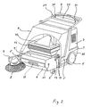
Figur 1- zeigt in perspektivischer Darstellung eine handgeführte Kehrmaschine.
Figur 2- zeigt die handgeführte Kehrmaschine aus
Figur 1 in perspektivischer Darstellung teilweise aufgebrochen und vereinfacht dargestellt. Figur 3- zeigt in einer seitlichen Prinzip-Teildarstellung die Kehrmaschine gemäß
Figuren 1 und 2, wobei sich das Filtergehäuse in seiner abgesenkten Stellung befindet. Figur 4- zeigt in einer Darstellung entsprechend
Figur 3 die Kehrmaschine mit sich in der angehobenen Stellung befindendem Filtergehäuse. Figur 5- zeigt in einer Prinzipdarstellung Einzelheiten des Filtergehäuses, das sich in der angehobenen Stellung befindet.
Figur 6- zeigt die Kehrmaschine in einer Prinzipdarstellung
ähnlich Figur 3, jedoch vervollständigt, so daß u.a. eine Führung und Halterung für den Schmutzbehälter zu erkennen ist.
- Figure 1
- shows a perspective view of a hand-held sweeper.
- Figure 2
- shows the hand-held sweeper from Figure 1 in a perspective view partially broken away and shown in simplified form.
- Figure 3
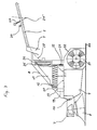
- shows a partial side view of the principle of the sweeper according to Figures 1 and 2, wherein the filter housing is in its lowered position.
- Figure 4
- shows in a representation corresponding to Figure 3, the sweeper with the filter housing in the raised position.
- Figure 5
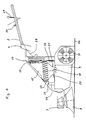
- shows in a schematic representation details of the filter housing, which is in the raised position.
- Figure 6
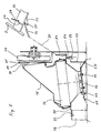
- shows the sweeper in a schematic diagram similar to Figure 3, but completed, so that, among other things, a guide and bracket for the dirt container can be seen.
Die dargestellte Kehrmaschine hat einen Maschinenrahmen 1, an dem in nicht dargestellter, üblicher Weise die Räder 5 und 6 befestigt sind und auf dem sich in einem Gehäuse 3 ein Antrieb, etwa ein mittels Batterie angetriebener Elektromotor oder ein Verbrennungsmotor befindet. Am Maschinenrahmen 1 ist ein sich nach hinten erstreckender Holm 2 befestigt, mit dessen Hilfe die Bedienungsperson die Maschine führt. Am vorderen Ende des Maschinenrahmens 1 ist zwischen Teile des Maschinenrahmens 1 bildenden, seitlichen Trägern 1′ ein nach hinten offener Schmutzbehälter 9 gehaltert, der in seinem hinteren oberen Bereich mittels sich schräg von oben nach unten und vorn erstreckender, im Abstand voneinander verlaufender Lamellen 13 (Figur 2) einen oberen Öffnungsbereich bildet. Zwischen der hinteren, nicht gezeigten Öffnung des Schmutzbehälters 9 und den Rädern 5 befindet sich eine Kehrwalze 31, die nach hinten und oben sowie seitlich von einem Gehäuseteil 32 abgedeckt wird und die im Betrieb der Kehrmaschine so angetrieben wird, daß sie sich, wie durch die Pfeile in den Figuren 3 und 4 angedeutet, im Uhrzeigersinn dreht und Schmutz vom Boden 40 durch die nicht gezeigte hintere Öffnung in den Schmutzbehälter 9 wirft.The sweeper shown has a
In diesem Zusammenhang sei erwähnt, daß selbstverständlich auch ein Aufbau der Kehrmaschine gewählt werden kann, bei dem die Kehrmaschine den Schmutz vom Boden über ihren oberen Umfangsbereich (über Kopf) in den Schmutzbehälter schleudert.In this context, it should be mentioned that, of course, a structure of the sweeper can also be selected, in which the sweeper throws the dirt from the floor over its upper peripheral region (overhead) into the dirt container.
Wie dargestellt, ist zwischen dem oberen Öffnungsbereich des Schmutzbehälters 9, also dem die Lamellen 13 aufweisenden Bereich, und einem weiter oben im Maschinengehäuse 1 untergebrachten Gebläsegehäuse 25 ein Filtergehäuse 15 gehaltert, dessen Einlaßöffnung 18 (Figuren 3 und 4) unmittelbar oberhalb des oberen Öffnungsbereichs des Schmutzbehälters 9 liegt und dessen Auslaßöffnung 17 (Figur 4) sich in der Stellung gemäß Figuren 2, 3 und 6 in Strömungsverbindung mit der im Gebläsegehäuse 25 vorhandenen Einlaßöffnung 16 des Gebläses 26 befindet, so daß im Betrieb des Gebläses 26 von diesem Luft durch die Einlaßöffnung 18 in das Filtergehäuse 15 und damit durch den in den Figuren 2 bis 4 und 6 angedeuteten Filter 16 und durch die Auslaßöffnung 17 aus dem Filtergehäuse 15 herausgesaugt wird.As shown, a
Im Betrieb fährt die Kehrmaschine vom Benutzer am Holm 2 geführt und über die Räder 5 angetrieben in den Figuren 3, 4 und 6 von rechts nach links über den Boden 40, wobei sich, wie bereits erwähnt, die aus einer Bürste bestehende Kehrwalze 31 im Uhrzeigersinn und damit entgegen der Fahrtrichtung dreht. Bei diesem Betrieb kann wahlweise auch der an einem Arm 7 gehalterte Besenteller 8 in Eingriff mit dem zu reinigenden Boden gebracht und entsprechend gedreht werden. Wird dieser Besenteller nicht benötigt, wird der Arm 7 vom Benutzer von Hand um die Achse 14 nach oben verschwenkt, so daß sich der Besenteller 8 oberhalb des Schmutzbehälters 9 und im Bereich der Abdeckhaube 4 befindet, die das Filtergehäuse 15 abdeckt und die entweder abnehmbar oder in nicht dargesteller Weise an ihrem oberen hinteren Ende angelenkt und somit in eine angehobene Stellung verschwenkbar ist.In operation, the sweeper is guided by the user on the
Das Filtergehäuse 15 ist an einem Trägerrahmen 20 befestigt, der um eine Achse 23 schwenkbar mittels Schrauben an am Maschinenrahmen 1 vorgesehenen Stützen 19 befestigt ist, die an den seitlichen Trägern 1′ angeordnet sind und sich nach oben über den Schmutzbehälter 9 erstrecken. Die Schwenkachse 23 liegt somit ebenfalls am vorderen Endbereich der Kehrmaschine und daher an der Vorderseite des Filtergehäuses 15 und auf einer Höhe etwa auf der Mitte zwischen Einlaßöffnung 18 und unterer Kante der Auslaßöffnung 17 des Filtergehäuses 15. Dabei ist der Abstand der Schwenkachse 23 von der Mitte der Einlaßöffnung 18 deutlich geringer als von der Mitte der Auslaßöffnung 17, nämlich nur etwas mehr als die Hälfte. Der Trägerrahmen 20 ruht in den Stellungen gemäß Figuren 3 und 6 an der den Stützen 19 gegenüberliegenden Seiten auf einer Stützstrebe 21 und wird durch eine Zugfeder 22 gegen diese Stützstrebe 21 gezogen. Die Zugfeder 22 greift mit ihrem oberen Ende an einer Lasche 50 an, die am Halterahmen 20 oder am Filtergehäuse 15 befestigt ist, und ist mit ihrem unteren Ende am Maschinenrahmen 1 angebracht.The
In der Stellung, in der der Halterahmen 20 bzw. das Filtergehäuse 15 auf der Stützstrebe 21 ruht, liegt der Umfangsrand der Auslaßöffnung 17 des Filtergehäuses 15 an einer die Ansaugöffnung 27 des Gebläses 26 umgebenden, stationären Wand 27′ dichtend an.In the position in which the
Die Einlaßöffnung 18 des Filtergehäuses 15 ist von einem Flanschrahmen 42 umgeben (Figur 5), der aus zwei mittels Schrauben 43 zusammengedrückten Rahmenhälften bestehen, zwischen denen eine umlaufende, lappenförmige Dichtungsanordnung 24, etwa aus Kautschuk oder flexiblem Kunststoff eingeklemmt ist. Diese umlaufende Dichtungsanordnung 24 liegt bei eingesetztem Schmutzbehälter 9 mit ihrem äußeren Bereich in jeder Stellung des Filtergehäuses 15 auf der oberen Wand 9′ des Schmutzbehälters 9 auf und umgibt so den oberen Öffnungsbereich des Schmutzbehälters 9 in dichtender Weise. Es sei erwähnt, daß diese abdichtende Lage in Figur 4 wegen der vereinfachten Darstellung nicht zu erkennen ist, jedoch in Figur 5 gezeigt wird.The inlet opening 18 of the
Das Filtergehäuse 15 besteht in der in den Figuren 3 bis 5 angedeuteten Weise aus einem unteren und einem oberen Teil, die in nicht näher zu beschreibender Weise lösbar miteinander verbunden sind und zwischen denen der kastenförmige Filter 16 gehalten wird.The
An der am Trägerrahmen 1 bzw. am Filtergehäuse 15 befestigten Lasche 50 greift ein Ende 51 einer Betätigungseinrichtung 28 an, deren anderes Ende 52 mit einem Betätigungshebel 29 verbunden ist. Die Betätigungseinrichtung 28 kann beispielsweise ein Bowdenzug oder ein Gestänge sein. Der Betätigungshebel 29 ist um einen Anlenkpunkt 29′ schwenkbar an einer am Führholm 2 befestigten, nur in Figur 5 angedeuteten Trägerplatte 53 befestigt und erstreckt sich durch einen Führungsschlitz 54, der in einer Querstrebe 32 ausgebildet ist, die oberhalb der Trägerplatte 53 am Führholm 2 befestigt ist und an der auch das Betätigungselement 30 für den Hauptschalter und der Hebel 31 für die Umkehr der Fahrtrichtung angebracht sind (Figur 2). Das Ende 52 der Betätigungseinrichtung 28 ist zwischen der Trägerplatte 53 und der Querstrebe 32 am Betätigungshebel 29 befestigt.One
In der Stellung gemäß Figuren 2, 3 und 6 ruht, wie bereits erwähnt, das Filtergehäuse 15 auf der Stützstrebe 21, so daß sich die Einlaßöffnung 18 des Filtergehäuses 15 in ihrer tiefsten Lage befindet und seine Auslaßöffnung 18 mit ihrem Randbereich dichtend an der Wand 27′ anliegt und so in Strömungsverbindung mit der Ansaugöffnung 27 des Gebläses 26 steht. Wird die Kehrmaschine in dieser Stellung des Filtergehäuses 15 benutzt, so erzeugt das Gebläse 26 einen Luftstrom durch den Schmutzbehälter 9, die Einlaßöffnung 18 des Filtergehäuses 15, den Filter 16 und die Auslaßöffnung 17 des Filtergehäuses 15 in das Gebläse 26, wodurch von der Kehrwalze 31 aufgewirbelter Feinstaub im Filter 16 niedergeschlagen wird.In the position according to FIGS. 2, 3 and 6, as already mentioned, the
Wenn mit der Kehrmaschine leichtes Granulat, etwa aus Polystyrol, oder feuchter Schmutz aufgenommen werden soll, wird der Betätigungshebel 29 vom Benutzer entlang dem Führschlitz 54 aus der Stellung gemäß Figur 2 in die Stellung gemäß Figur 5 verschwenkt, in der er in einen Verriegelungsabschnitt des Führschlitzes 54 eingreift. Durch diese Bewegung des Betätigungshebels 29 wird über die Betätigungseinrichtung 28 das hintere Ende des Filtergehäuses 15 gegen die Kraft der Feder 22 angehoben und das ganze Filtergehäuse 15 um die Achse 23 verschwenkt, so daß es in die Lage gemäß Figuren 4 und 5 gelangt, in der zwischen Auslaßöffnung 17 des Filtergehäuses 15 und Ansaugöffnung 27 des Gebläses 26 ein sich nach oben öffnender Spalt vorhanden ist und in der der die Einlaßöffnung 18 des Filtergehäuses 15 umgebende Flanschrahmen 42 eine leicht von vorn nach hinten und oben geneigte Lage einnimmt (Figur 5). In dieser Lage ergibt sich eine entsprechende Verformung der Dichtungsanordnung 24, jedoch bleibt die umlaufende Dichtungsanorndung 24 infolge ihrer Flexibilität und Elastizität an allen Stellen in abdichtender Berührung mit der den oberen Öffnungsbereich des Schmutzbehälters 9 umgebenden Wandbereich 9′.If light granulate, for example made of polystyrene, or moist dirt is to be picked up with the sweeper, the actuating
Infolge des zwischen Auslaßöffnung 17 des Filtergehäuses 15 und Ansaugöffnung 27 des Gebläses 26 gebildeten Spaltes saugt das Gebläse 26 nunmehr durch diesen Spalt Luft aus der Umgebung und nicht mehr durch das Filtergehäuse 15 an. Daher ergibt sich auch keine Saugwirkung mehr auf den von der Kehrwalze 31 in den Schmutzbehälter 9 geschleuderten Schmutz.As a result of the gap formed between the outlet opening 17 of the
Will der Benutzer die Kehrmaschine wieder mit einem ansaugenden Luftstrom durch das Filtergehäuse 15 betreiben, so bewegt er den Betätigungshebel 29 aus dem Verriegelungsabschnitt des Führschlitzes 54 heraus, und das Filtergehäuse 15 kehrt durch sein Eigengewicht und unterstützt von der Kraft der Feder 22 in die Lage gemäß Figuren 3 und 6 zurück, in der die Auslaßöffnung 17 des Filtergehäuses 15 dichtend an der die Ansaugöffnung 27 des Gebläses 26 umgebenden Wand 27′ anliegt. Bei dieser Bewegung nimmt das Filtergehäuse 15 im übrigen auch den Betätigungshebel 29 mit und bewegt ihn in die Stellung gemäß Figur 2.If the user wants to operate the sweeper again with an intake air flow through the
Will der Benutzer den Filter 16 von Schmutzablagerungen reinigen, so kann er den Hebel 29 innerhalb des Führschlitzes 54 hin- und herbewegen, ohne dabei den Betätigungshebel 29 in Eingriff mit dem Verriegelungsabschnitt des Führschlitzes 54 zu bringen. Bei dieser Hin- und Herbewegung des Betätigungshebels 29 wird entsprechend auch das Filtergehäuse 15 um die Achse 23 hin- und herverschwenkt. Insbesondere bei jedem Aufschlagen des Trägerrahmen 20 bzw. des filtergehäuses 15 auf die Stützstrebe 21 ergibt sich eine starke Erschütterung, durch die Schmutz aus dem Filter 16 gelöst wird und durch die Einlaßöffnung 18 in den Schmutzbehälter 9 fällt. Da bei den derart durchgeführten Hin- und Herverschwenkungen des Filtergehäuses 15 die Dichtungsanordnung 24 immer den oberen Öffnungsbereich umgebend auf der Deckwand 9′ des Schmutzbehältes 9 aufliegt, tritt kein Schmutz, insbesondere kein Feinstaub, der aus dem Filter 16 gelöst wird, im Bereich zwischen Einlaßöffnung 18 des Filtergehäuses 15 und oberem Öffnungsbereich des Schmutzbehälters 9 aus. Darüber hinaus leiten die nach vorn geneigten Lamellen 13 im oberen Öffnungsbereich des Schmutzbehälters 9 den herabfallenden Schmutz von der hinteren Öffnung des Schmutzbehälters 9 weg, so daß auch an dieser Stelle die Gefahr des Austritts von Schmutz verringert ist.If the user wants to clean the
Wie bereits erwähnt, ist der Schmutzbehälter 9 zwischen den beiden sich nach vorn erstreckenden Seitenträgern 1′ des Rahmens 1 gehaltert, und er kann nach vorn aus der Kehrmaschine entfernt und von vorn wieder in die Kehrmaschine eingesetzt werden. Hierzu sind an jeder Seitenwand des Schmutzbehälters 9 Halterungsvorsprünge 11 und 12 ausgebildet, die im eingesetzten Zustand auf aus Schienen bestehenden, an den Seitenträgern 1′ angebrachten Führungen 35, 36 bestehen. Wie in Figur 6 zu erkennen ist, ruht bei eingesetztem Schmutzbehälter 9 der hintere Vorsprung 12 auf einem im wesentlichen parallel zum Boden 40 und damit zur Standebene der Maschine verlaufenden hinteren Führungsabschnitt 35, dessen hinteres Ende einen nach oben abgewinkelten Abschnitt 38 hat, der eine weitere Einschubbewegung des Schmutzbehälters 9 über die dargestellte Lage hinaus verhindert. Der vordere Vorsprung 11 ruht an einer Vorsprungsfläche 37, die im Bereich des vorderen Abschnittes 36 der Führung ausgebildet ist, wobei der vordere Abschnitt 36 der Führung schräg nach vorn und unten verläuft und an einer Stelle endet, die einen geringeren Abstand von der Standebene der Maschine hat, als der Abstand der unteren Seite der Vorsprünge 11 und 12 von der Bodenwand des Schmutzbehälters 9. Die Vorsprungsfläche 37 liegt, wie zu erkennen ist, kurz vor dem Übergang vom vorderen Abschnitt 36 zum hinteren Abschnitt 35 der Führung, wobei der Abstand der Vorsprungsfläche 37 von dem Beginn des hinteren Abschnittes 35 größer als der Durchmesser des Vorsprungs 11 ist.As already mentioned, the
Wie ohne weiteres aus der Darstellung gemäß Figur 6 zu erkennen ist, ruht der Schmutzbehälter 9 im eingesetzten Zustand mit seinen seitlichen Vorsprüngen 11 und 12 auf den die Führung bildenden Abschnitten 35 und 36 der Schienen, wobei sich der Vorsprung 12 am hinteren Ende des Abschnittes 35 befindet, während der Vorsprung 11 im Bereich des vorderen Abschnittes 36 an der Vorsprungsfläche 37 anliegt, so daß der Schmutzbehälter 9 sich selbsttätig weder nach unten noch nach vorn verlagern kann.As can easily be seen from the illustration according to FIG. 6, the
Um den Schmutzbehälter 9 zum Entleeren aus der Maschine herauszunehmen, schwenkt der Benutzer den Arm 7 mit dem Besenteller 8 nach oben. Dann ergreift er den Griff 10 (Figur 2) am vorderen Ende des Schmutzbehälters 9 und hebt den Schmutzbehälter 9 geringfügig an, so daß der Vorsprung 11 aus dem Bereich der Vorsprungsfläche 37 des Abschnittes 36 der Führung kommt und dann vom Benutzer nach vorn herausgezogen werden kann, wobei der Vorsprung 12 auf dem Abschnitt 35 und dann auch auf dem Abschnitt 36 gleitet, ohne daß seine Verlagerungsbewegung durch die Vorsprungsfläche 37 behindert würde, da der Vorsprung 12, wie dargestellt, eine deutlich größere Abmessung als die Vorsprungsfläche 37 sowie abgerundete Umfangsflächen hat, so daß er über die Vorsprungsfläche 37 gleiten kann.In order to remove the
Bei dieser Entnahmebewegung befindet sich das Filtergehäuse 15 üblicherweise in der abgesenkten Stellung gemäß Figuren 3 und 6, und der Schmutzbehälter gleitet einfach unter dem Bereich der Eintrittsöffnung 18 des Filtergehäuses 15 weg, wobei die lappenförmige Dichtungsanordnung 24 über die Deckwand 9′ des Schmutzbehälters 9 rutscht.With this removal movement, the
Der entnommene Schmutzbehälter 9 kann dann in üblicher Weise entleert werden.The removed
Um den Schmutzbehälter 9 wieder einzusetzen, braucht der Benutzer ihn lediglich mit seiner Bodenfläche vor den Aufnahmebereich der Kehrmaschine auf den Boden zu legen und dann die Kehrmaschine auf den Schmutzbehälter 9 zuzufahren. Bei dieser Zusammenführungsbewegung kommt der Vorsprung 12 in Eingriff mit dem vorderen Abschnitt 36 der Führung und gleitet diese Führung hinauf, worauf dann auch der Vorsprung 11 in Eingriff mit dem vorderen Endbereich des Abschnittes 36 der Führung kommt und auf diese gleitet, bis der Vorsprung 11 über die Vorsprungsfläche 37 rutscht und so der Schmutzbehälter 9 in der eingesetzten, in Figur 6 gezeigten Lage "verriegelt" wird.In order to reinsert the
Bei dieser Einschubbewegung des Schmutzbehälters 9 bewegt sich der Schmutzbehälter in der Maschine nach hinten und oben und wird so gegen die Dichtungsanordnung 24 geführt, die bei eingesetztem Schmutzbehälter 9 dann in der beschriebenen Weise seinen oberen Öffnungsbereich dichtend umgibt.During this push-in movement of the
Claims (10)
- A hand-controlled sweeping machine comprising a sweeping roller (31) mounted in a machine frame (1) and driven so as to rotate and a releasably arranged dirt container (9) for receiving the dirt thrown up by the sweeping roller (31) and a filter housing (15), which is pivotable between a lowered and a raised position relative to the dirt container (9), whose inlet opening (18) is arranged above an upper opening region of the dirt container (9) and whose outlet opening (17) is arranged adjacent a fan (26) drawing air through the filter housing (15) and is arranged on the rear side of the filter housing (15) in relation to the normal direction of travel of the sweeping machine, characterised in that the filter housing (15) is movable about a pivot axis (23), which is provided on the front side of said filter housing and whose distance from the centre of the inlet opening (18) of the filter housing (15) is smaller than its distance from the centre of the outlet opening (17) of said filter housing (15), and the outlet opening (17) of the filter housing (15) in the latter's lowered position connects the internal chamber of the filter housing (15) with the suction opening (27) of the fan (26) and in the raised position is arranged at least with a partial portion at a distance from the suction opening (27) of the fan (26), so that a bypass opening is formed for the fan (28).
- A sweeping machine according to claim 1, characterised in that the distance of the pivot axis (23) from the centre of the inlet opening (18) of the filter housing (15) measures half to two-thirds the distance from the outlet opening (17).
- A sweeping machine according to claim 1 or 2, characterised in that the pivot axis (23) lies at a height between the outlet opening (17) and the inlet opening (18) of the filter housing (15).
- A sweeping machine according to one of claims 1 to 3, characterised in that the edge region of the outlet opening (17) of the filter housing (15) in the lowered position rests against a sealing surface (27') enclosing the suction opening (27) of the fan (26).
- A sweeping machine according to one of claims 1 to 4, characterised in that the inlet opening (18) of the filter housing (15) lies directly above the upper opening region of the dirt container (9).
- A sweeping machine according to one of claims 1 to 5, characterised in that arranged on a wall section (42) enclosing the inlet opening (18) of the filter housing (15) is a flap-shaped sealing arrangement (24), which encloses the inlet opening (18) and in all positions of the filter housing (15) rests upon the lid wall (9') of the dirt container (9) with its outer circumference enclosing the upper opening region of the inserted dirt container (9).
- A sweeping machine according to one of claims 1 to 6, characterised in that the filter housing (15) is movable against spring force from the lowered position into the raised position.
- A sweeping machine according to claim 7, characterised in that a tension spring (22) acts upon the rear side of the filter housing (15) and the rear side of the filter housing (15) rests in the lowered position upon an upright (21) provided on the machine frame (1).
- A sweeping machine according to one of claims 1 to 8, characterised in that the filter housing (15) is held so as to be lockable in the raised position.
- A sweeping machine according to one of claims 1 to 9, characterised in that an operating device (28) for pivoting the filter housing (15) acts upon the rear side of the filter housing (15) and the operating element (29) of the operating device (28) is mounted on the backwardly extending guide handle (2) of the sweeping machine.
Priority Applications (3)
| Application Number | Priority Date | Filing Date | Title |
|---|---|---|---|
| DE8787118653T DE3779649D1 (en) | 1987-12-16 | 1987-12-16 | HAND-MADE SWEEPER. |
| EP87118653A EP0321592B1 (en) | 1987-12-16 | 1987-12-16 | Hand-controlled sweeping apparatus |
| US07/285,042 US4974283A (en) | 1987-12-16 | 1988-12-15 | Hand-guided sweeping machine |
Applications Claiming Priority (1)
| Application Number | Priority Date | Filing Date | Title |
|---|---|---|---|
| EP87118653A EP0321592B1 (en) | 1987-12-16 | 1987-12-16 | Hand-controlled sweeping apparatus |
Publications (2)
| Publication Number | Publication Date |
|---|---|
| EP0321592A1 EP0321592A1 (en) | 1989-06-28 |
| EP0321592B1 true EP0321592B1 (en) | 1992-06-03 |
Family
ID=8197519
Family Applications (1)
| Application Number | Title | Priority Date | Filing Date |
|---|---|---|---|
| EP87118653A Expired - Lifetime EP0321592B1 (en) | 1987-12-16 | 1987-12-16 | Hand-controlled sweeping apparatus |
Country Status (3)
| Country | Link |
|---|---|
| US (1) | US4974283A (en) |
| EP (1) | EP0321592B1 (en) |
| DE (1) | DE3779649D1 (en) |
Cited By (2)
| Publication number | Priority date | Publication date | Assignee | Title |
|---|---|---|---|---|
| DE102007025763B3 (en) * | 2007-05-23 | 2009-01-22 | Alfred Kärcher Gmbh & Co. Kg | Sweeper suction machine i.e. hand-operated walk behind-suction machine, has suction channel limited in sections by filter cover, and suction unit arranged at end of suction channel turned to filter device |
| CN107119614A (en) * | 2017-06-29 | 2017-09-01 | 合肥川达信息科技有限责任公司 | A kind of device for collecting fallen leaves |
Families Citing this family (47)
| Publication number | Priority date | Publication date | Assignee | Title |
|---|---|---|---|---|
| US5390387A (en) * | 1994-06-09 | 1995-02-21 | Dube; Gerald | Lightweight self-propelled turf sweeper |
| US5867965A (en) * | 1995-03-10 | 1999-02-09 | Pilz; Jack | Tile setting machine |
| US5647093A (en) * | 1996-06-18 | 1997-07-15 | Tennant Company | Sweeper with dual seal filter |
| US8788092B2 (en) | 2000-01-24 | 2014-07-22 | Irobot Corporation | Obstacle following sensor scheme for a mobile robot |
| US8412377B2 (en) | 2000-01-24 | 2013-04-02 | Irobot Corporation | Obstacle following sensor scheme for a mobile robot |
| US6956348B2 (en) | 2004-01-28 | 2005-10-18 | Irobot Corporation | Debris sensor for cleaning apparatus |
| US6735814B2 (en) | 2000-10-05 | 2004-05-18 | Mister Services, Inc. | Apparatus for cleaning hard-to-reach areas |
| US6690134B1 (en) | 2001-01-24 | 2004-02-10 | Irobot Corporation | Method and system for robot localization and confinement |
| US7571511B2 (en) | 2002-01-03 | 2009-08-11 | Irobot Corporation | Autonomous floor-cleaning robot |
| US8396592B2 (en) | 2001-06-12 | 2013-03-12 | Irobot Corporation | Method and system for multi-mode coverage for an autonomous robot |
| US7663333B2 (en) | 2001-06-12 | 2010-02-16 | Irobot Corporation | Method and system for multi-mode coverage for an autonomous robot |
| US9128486B2 (en) | 2002-01-24 | 2015-09-08 | Irobot Corporation | Navigational control system for a robotic device |
| US8386081B2 (en) | 2002-09-13 | 2013-02-26 | Irobot Corporation | Navigational control system for a robotic device |
| US8428778B2 (en) | 2002-09-13 | 2013-04-23 | Irobot Corporation | Navigational control system for a robotic device |
| US7332890B2 (en) | 2004-01-21 | 2008-02-19 | Irobot Corporation | Autonomous robot auto-docking and energy management systems and methods |
| JP2007530978A (en) | 2004-03-29 | 2007-11-01 | エヴォリューション ロボティクス インコーポレイテッド | Position estimation method and apparatus using reflected light source |
| US9008835B2 (en) | 2004-06-24 | 2015-04-14 | Irobot Corporation | Remote control scheduler and method for autonomous robotic device |
| US8972052B2 (en) | 2004-07-07 | 2015-03-03 | Irobot Corporation | Celestial navigation system for an autonomous vehicle |
| US7706917B1 (en) | 2004-07-07 | 2010-04-27 | Irobot Corporation | Celestial navigation system for an autonomous robot |
| EP2145573B1 (en) | 2005-02-18 | 2011-09-07 | iRobot Corporation | Autonomous surface cleaning robot for wet and dry cleaning |
| US8392021B2 (en) | 2005-02-18 | 2013-03-05 | Irobot Corporation | Autonomous surface cleaning robot for wet cleaning |
| US7620476B2 (en) | 2005-02-18 | 2009-11-17 | Irobot Corporation | Autonomous surface cleaning robot for dry cleaning |
| US7389156B2 (en) | 2005-02-18 | 2008-06-17 | Irobot Corporation | Autonomous surface cleaning robot for wet and dry cleaning |
| US7500284B2 (en) * | 2005-02-24 | 2009-03-10 | Pacific Omega Pack Enterprises Ltd. | Turf sweeper and debris removal machine |
| US8930023B2 (en) | 2009-11-06 | 2015-01-06 | Irobot Corporation | Localization by learning of wave-signal distributions |
| EP2270619B1 (en) | 2005-12-02 | 2013-05-08 | iRobot Corporation | Modular robot |
| KR101099808B1 (en) | 2005-12-02 | 2011-12-27 | 아이로보트 코퍼레이션 | Robot system |
| ES2623920T3 (en) | 2005-12-02 | 2017-07-12 | Irobot Corporation | Robot system |
| KR101300492B1 (en) | 2005-12-02 | 2013-09-02 | 아이로보트 코퍼레이션 | Coverage robot mobility |
| EP2816434A3 (en) | 2005-12-02 | 2015-01-28 | iRobot Corporation | Autonomous coverage robot |
| WO2007109624A2 (en) | 2006-03-17 | 2007-09-27 | Irobot Corporation | Robot confinement |
| EP2548489B1 (en) | 2006-05-19 | 2016-03-09 | iRobot Corporation | Removing debris from cleaning robots |
| US8417383B2 (en) | 2006-05-31 | 2013-04-09 | Irobot Corporation | Detecting robot stasis |
| US8230540B1 (en) | 2007-04-24 | 2012-07-31 | Nelson Marc O | Cordless sweeper |
| KR101339513B1 (en) | 2007-05-09 | 2013-12-10 | 아이로보트 코퍼레이션 | Autonomous coverage robot |
| CN105147193B (en) | 2010-02-16 | 2018-06-12 | 艾罗伯特公司 | Vacuum brush |
| CN106462161B (en) | 2014-03-31 | 2020-03-06 | 美国iRobot公司 | Autonomous mobile robot |
| US9516806B2 (en) | 2014-10-10 | 2016-12-13 | Irobot Corporation | Robotic lawn mowing boundary determination |
| US9510505B2 (en) | 2014-10-10 | 2016-12-06 | Irobot Corporation | Autonomous robot localization |
| US9420741B2 (en) | 2014-12-15 | 2016-08-23 | Irobot Corporation | Robot lawnmower mapping |
| US9538702B2 (en) | 2014-12-22 | 2017-01-10 | Irobot Corporation | Robotic mowing of separated lawn areas |
| US9848750B1 (en) | 2015-06-30 | 2017-12-26 | Eric Watkins | Manually-operated floor sweeper |
| US11115798B2 (en) | 2015-07-23 | 2021-09-07 | Irobot Corporation | Pairing a beacon with a mobile robot |
| US10021830B2 (en) | 2016-02-02 | 2018-07-17 | Irobot Corporation | Blade assembly for a grass cutting mobile robot |
| US10459063B2 (en) | 2016-02-16 | 2019-10-29 | Irobot Corporation | Ranging and angle of arrival antenna system for a mobile robot |
| WO2019013989A1 (en) | 2017-07-14 | 2019-01-17 | Irobot Corporation | Blade assembly for a grass cutting mobile robot |
| DE102020109656A1 (en) * | 2020-04-07 | 2021-10-07 | Alfred Kärcher SE & Co. KG | Filter unit for a cleaning machine, floor cleaning machine and method for operating a floor cleaning machine |
Family Cites Families (9)
| Publication number | Priority date | Publication date | Assignee | Title |
|---|---|---|---|---|
| US2702377A (en) * | 1948-10-01 | 1955-02-15 | Vossloh Werke Gmbh | Holder with retaining means for electrical discharge tubes having pin contacts on their bases |
| US2784440A (en) * | 1955-05-26 | 1957-03-12 | Wayne Manufacturing Co | Industrial sweeping machines |
| US2972159A (en) * | 1956-06-18 | 1961-02-21 | Tennant Co G H | Power sweeper |
| US3189931A (en) * | 1961-09-13 | 1965-06-22 | Tennant Co G H | Power sweeper improvements |
| US3879789A (en) * | 1970-09-15 | 1975-04-29 | Tennant Co | Scrubbing machine |
| US3813725A (en) * | 1972-08-17 | 1974-06-04 | Atwater Strong Co Inc | Vacuum cleaner construction |
| US3942215A (en) * | 1972-11-13 | 1976-03-09 | Olds James O | Floor maintenance machine |
| US4327455A (en) * | 1980-12-04 | 1982-05-04 | The Scott & Fetzer Company | Surface cleaning machine with hopper dumping mechanism |
| US4580313A (en) * | 1983-09-12 | 1986-04-08 | Tennant Company | Walk behind floor maintenance machine |
-
1987
- 1987-12-16 DE DE8787118653T patent/DE3779649D1/en not_active Expired - Lifetime
- 1987-12-16 EP EP87118653A patent/EP0321592B1/en not_active Expired - Lifetime
-
1988
- 1988-12-15 US US07/285,042 patent/US4974283A/en not_active Expired - Fee Related
Cited By (2)
| Publication number | Priority date | Publication date | Assignee | Title |
|---|---|---|---|---|
| DE102007025763B3 (en) * | 2007-05-23 | 2009-01-22 | Alfred Kärcher Gmbh & Co. Kg | Sweeper suction machine i.e. hand-operated walk behind-suction machine, has suction channel limited in sections by filter cover, and suction unit arranged at end of suction channel turned to filter device |
| CN107119614A (en) * | 2017-06-29 | 2017-09-01 | 合肥川达信息科技有限责任公司 | A kind of device for collecting fallen leaves |
Also Published As
| Publication number | Publication date |
|---|---|
| DE3779649D1 (en) | 1992-07-09 |
| US4974283A (en) | 1990-12-04 |
| EP0321592A1 (en) | 1989-06-28 |
Similar Documents
| Publication | Publication Date | Title |
|---|---|---|
| EP0321592B1 (en) | Hand-controlled sweeping apparatus | |
| EP0320526B1 (en) | Hand-controlled sweeping apparatus | |
| DE10357635B4 (en) | Floor cleaning device | |
| DE69918564T2 (en) | CONSTRUCTION OF A VACUUM CLEANER | |
| DE2660419C2 (en) | Street sweeper | |
| DE2411471C3 (en) | Floor care machine | |
| DE4100333C2 (en) | Mechanism for height adjustment of floor cleaning devices | |
| DE69721271T2 (en) | Handstaubsauger | |
| DE69723614T2 (en) | Large format cleaning device | |
| DE19907122C2 (en) | Suction nozzle for a vacuum cleaner | |
| DE10110906A1 (en) | sweeper | |
| DE19719493A1 (en) | Floor cleaning machine with suction scraper | |
| DE10296627T5 (en) | Movement mechanism drive system with switchover for smooth floor | |
| DE3417163A1 (en) | VACUUM CLEANER | |
| EP1380246A2 (en) | Suction device for cleaning purposes | |
| DE973926C (en) | Vacuum cleaner, especially for households, with a cleaning device for the dust filter | |
| EP0587713A1 (en) | Sweeping unit. | |
| DE2852032A1 (en) | VACUUM CLEANER | |
| DE2856115A1 (en) | Easily emptied heavy duty vacuum cleaner - has low-level centre of gravity for easy movement | |
| DE8508144U1 (en) | Bristle strips for floor nozzles | |
| DE19601976A1 (en) | Floor sweeper with rotary brush | |
| DE102015105587A1 (en) | Floor cleaning machine | |
| DE19715435A1 (en) | Street cleaning machine with brushes | |
| DE3213089A1 (en) | Sweeping machine | |
| DE3117234A1 (en) | PANEL WIPER |
Legal Events
| Date | Code | Title | Description |
|---|---|---|---|
| PUAI | Public reference made under article 153(3) epc to a published international application that has entered the european phase |
Free format text: ORIGINAL CODE: 0009012 |
|
| AK | Designated contracting states |
Kind code of ref document: A1 Designated state(s): AT BE CH DE ES FR GB GR IT LI LU NL SE |
|
| 17P | Request for examination filed |
Effective date: 19890712 |
|
| RBV | Designated contracting states (corrected) |
Designated state(s): CH DE FR GB IT LI NL |
|
| 17Q | First examination report despatched |
Effective date: 19910423 |
|
| GRAA | (expected) grant |
Free format text: ORIGINAL CODE: 0009210 |
|
| AK | Designated contracting states |
Kind code of ref document: B1 Designated state(s): CH DE FR GB IT LI NL |
|
| ITF | It: translation for a ep patent filed |
Owner name: ING. A. GIAMBROCONO & C. S.R.L. |
|
| GBT | Gb: translation of ep patent filed (gb section 77(6)(a)/1977) | ||
| REF | Corresponds to: |
Ref document number: 3779649 Country of ref document: DE Date of ref document: 19920709 |
|
| ET | Fr: translation filed | ||
| PLBE | No opposition filed within time limit |
Free format text: ORIGINAL CODE: 0009261 |
|
| STAA | Information on the status of an ep patent application or granted ep patent |
Free format text: STATUS: NO OPPOSITION FILED WITHIN TIME LIMIT |
|
| 26N | No opposition filed | ||
| PGFP | Annual fee paid to national office [announced via postgrant information from national office to epo] |
Ref country code: GB Payment date: 19971211 Year of fee payment: 11 |
|
| PGFP | Annual fee paid to national office [announced via postgrant information from national office to epo] |
Ref country code: FR Payment date: 19971216 Year of fee payment: 11 |
|
| PGFP | Annual fee paid to national office [announced via postgrant information from national office to epo] |
Ref country code: CH Payment date: 19971217 Year of fee payment: 11 |
|
| PGFP | Annual fee paid to national office [announced via postgrant information from national office to epo] |
Ref country code: NL Payment date: 19971231 Year of fee payment: 11 |
|
| PG25 | Lapsed in a contracting state [announced via postgrant information from national office to epo] |
Ref country code: GB Free format text: LAPSE BECAUSE OF NON-PAYMENT OF DUE FEES Effective date: 19981216 |
|
| PG25 | Lapsed in a contracting state [announced via postgrant information from national office to epo] |
Ref country code: LI Free format text: LAPSE BECAUSE OF NON-PAYMENT OF DUE FEES Effective date: 19981231 Ref country code: CH Free format text: LAPSE BECAUSE OF NON-PAYMENT OF DUE FEES Effective date: 19981231 |
|
| PG25 | Lapsed in a contracting state [announced via postgrant information from national office to epo] |
Ref country code: NL Free format text: LAPSE BECAUSE OF NON-PAYMENT OF DUE FEES Effective date: 19990701 |
|
| GBPC | Gb: european patent ceased through non-payment of renewal fee |
Effective date: 19981216 |
|
| REG | Reference to a national code |
Ref country code: CH Ref legal event code: PL |
|
| PG25 | Lapsed in a contracting state [announced via postgrant information from national office to epo] |
Ref country code: FR Free format text: LAPSE BECAUSE OF NON-PAYMENT OF DUE FEES Effective date: 19990831 |
|
| NLV4 | Nl: lapsed or anulled due to non-payment of the annual fee |
Effective date: 19990701 |
|
| REG | Reference to a national code |
Ref country code: FR Ref legal event code: ST |
|
| PGFP | Annual fee paid to national office [announced via postgrant information from national office to epo] |
Ref country code: DE Payment date: 20000223 Year of fee payment: 13 |
|
| PG25 | Lapsed in a contracting state [announced via postgrant information from national office to epo] |
Ref country code: DE Free format text: LAPSE BECAUSE OF NON-PAYMENT OF DUE FEES Effective date: 20011002 |
|
| PG25 | Lapsed in a contracting state [announced via postgrant information from national office to epo] |
Ref country code: IT Free format text: LAPSE BECAUSE OF NON-PAYMENT OF DUE FEES;WARNING: LAPSES OF ITALIAN PATENTS WITH EFFECTIVE DATE BEFORE 2007 MAY HAVE OCCURRED AT ANY TIME BEFORE 2007. THE CORRECT EFFECTIVE DATE MAY BE DIFFERENT FROM THE ONE RECORDED. Effective date: 20051216 |