WO2024004446A1 - Sound signal reproduction device, method for controlling sound signal reproduction device, and program for controlling sound signal reproduction device - Google Patents
Sound signal reproduction device, method for controlling sound signal reproduction device, and program for controlling sound signal reproduction device Download PDFInfo
- Publication number
- WO2024004446A1 WO2024004446A1 PCT/JP2023/019163 JP2023019163W WO2024004446A1 WO 2024004446 A1 WO2024004446 A1 WO 2024004446A1 JP 2023019163 W JP2023019163 W JP 2023019163W WO 2024004446 A1 WO2024004446 A1 WO 2024004446A1
- Authority
- WO
- WIPO (PCT)
- Prior art keywords
- audio signal
- vibration
- attached
- processor
- information
- Prior art date
Links
- 230000005236 sound signal Effects 0.000 title claims abstract description 108
- 238000000034 method Methods 0.000 title claims description 19
- 238000001514 detection method Methods 0.000 claims description 27
- 238000004891 communication Methods 0.000 claims description 22
- 230000033001 locomotion Effects 0.000 claims description 20
- 230000001052 transient effect Effects 0.000 claims description 13
- 230000008569 process Effects 0.000 claims description 4
- 230000013011 mating Effects 0.000 abstract 4
- 238000010586 diagram Methods 0.000 description 33
- 238000012545 processing Methods 0.000 description 6
- 230000009467 reduction Effects 0.000 description 5
- 238000012360 testing method Methods 0.000 description 4
- 230000003247 decreasing effect Effects 0.000 description 3
- 230000000694 effects Effects 0.000 description 3
- 230000014509 gene expression Effects 0.000 description 3
- 230000007246 mechanism Effects 0.000 description 3
- 230000008859 change Effects 0.000 description 2
- 230000007423 decrease Effects 0.000 description 2
- 238000005516 engineering process Methods 0.000 description 2
- 238000001914 filtration Methods 0.000 description 2
- 238000012986 modification Methods 0.000 description 2
- 230000004048 modification Effects 0.000 description 2
- 230000035945 sensitivity Effects 0.000 description 2
- 230000001133 acceleration Effects 0.000 description 1
- 230000003321 amplification Effects 0.000 description 1
- 230000005540 biological transmission Effects 0.000 description 1
- 239000004566 building material Substances 0.000 description 1
- 238000006243 chemical reaction Methods 0.000 description 1
- 238000013461 design Methods 0.000 description 1
- 230000007257 malfunction Effects 0.000 description 1
- 239000000463 material Substances 0.000 description 1
- 238000003199 nucleic acid amplification method Methods 0.000 description 1
- 238000010079 rubber tapping Methods 0.000 description 1
- 238000011895 specific detection Methods 0.000 description 1
Images


Classifications
-
- G—PHYSICS
- G06—COMPUTING; CALCULATING OR COUNTING
- G06F—ELECTRIC DIGITAL DATA PROCESSING
- G06F3/00—Input arrangements for transferring data to be processed into a form capable of being handled by the computer; Output arrangements for transferring data from processing unit to output unit, e.g. interface arrangements
- G06F3/01—Input arrangements or combined input and output arrangements for interaction between user and computer
- G06F3/03—Arrangements for converting the position or the displacement of a member into a coded form
- G06F3/041—Digitisers, e.g. for touch screens or touch pads, characterised by the transducing means
- G06F3/043—Digitisers, e.g. for touch screens or touch pads, characterised by the transducing means using propagating acoustic waves
-
- H—ELECTRICITY
- H04—ELECTRIC COMMUNICATION TECHNIQUE
- H04R—LOUDSPEAKERS, MICROPHONES, GRAMOPHONE PICK-UPS OR LIKE ACOUSTIC ELECTROMECHANICAL TRANSDUCERS; DEAF-AID SETS; PUBLIC ADDRESS SYSTEMS
- H04R1/00—Details of transducers, loudspeakers or microphones
-
- H—ELECTRICITY
- H04—ELECTRIC COMMUNICATION TECHNIQUE
- H04R—LOUDSPEAKERS, MICROPHONES, GRAMOPHONE PICK-UPS OR LIKE ACOUSTIC ELECTROMECHANICAL TRANSDUCERS; DEAF-AID SETS; PUBLIC ADDRESS SYSTEMS
- H04R3/00—Circuits for transducers, loudspeakers or microphones
Definitions
- the present disclosure relates to an audio signal reproducing device, a method of controlling the audio signal reproducing device, and a control program for the audio signal reproducing device.
- Patent Document 1 describes a technology in which a speaker unit that forcibly vibrates the mirror and generates sound from the mirror is attached to a bathroom mirror. Patent Document 1 also describes a technique in which a touch sensor is provided on the surface of a mirror in order to control the speaker unit.
- the present disclosure provides an audio signal reproducing device, a method for controlling the audio signal reproducing device, and a control program for the audio signal reproducing device, which can control audio reproduction.
- the audio signal reproducing device includes a vibration generator attached to one or more attached members, the attached member to which the vibration generator is attached, or the attached member to which the vibration generator is attached.
- a vibration sensor attached to a separate attached member; a drive device that drives the vibration generator based on an audio signal to generate sound via the attached member; a processor that executes a program; a storage device that stores a program to be executed, and by causing the processor to execute the program, a user generates a vibration on the attached member to which the vibration sensor is attached based on a signal acquired from the vibration sensor.
- Position information indicating the position of vibration is generated, and control information is transmitted based on the position information.
- FIG. 1 is a diagram showing a device configuration and a functional configuration of an audio signal reproducing device according to Embodiment 1.
- FIG. 7 is a diagram illustrating a first example of a user's operation on a third attached member in the first embodiment.
- FIG. 3 is a diagram showing detection results of vibrations generated by user operations in the first embodiment.
- 7 is a diagram illustrating a second example of a user's operation on the third attached member in the first embodiment.
- FIG. 7 is a diagram illustrating a third example of a user's operation on a third attached member in the first embodiment.
- FIG. 3 is a diagram illustrating a first example of relational information in the first embodiment;
- FIG. 1 is a diagram showing a device configuration and a functional configuration of an audio signal reproducing device according to Embodiment 1.
- FIG. 7 is a diagram illustrating a first example of a user's operation on a third attached member in the first embodiment.
- FIG. 3 is a diagram showing detection results of
- FIG. 3 is a diagram showing the device configuration and functional configuration of an audio signal reproducing device according to a second embodiment.
- FIG. 7 is a diagram showing the flow of audio signal reduction processing in Embodiment 2.
- FIG. 7 is a diagram showing detection results of vibrations generated by user operations in Embodiment 2.
- FIG. 7 is a diagram showing a device configuration and a functional configuration of an audio signal reproducing device according to a third embodiment.
- 12 is a diagram showing a fourth example of a user's operation on a third attached member in the third embodiment.
- FIG. 12 is a diagram showing example 5 of a user's operation on a third attached member in Embodiment 3.
- FIG. 7 is a diagram showing example 6 of a user's operation on a third attached member in Embodiment 3;
- FIG. 7 is a diagram showing a second example of relational information in the third embodiment.
- FIG. 7 is a diagram showing a device configuration and a functional configuration of an audio signal reproducing device according to a fourth embodiment. It is a figure which shows the example 3 of relationship information.
- FIG. 7 is a diagram showing example 4 of related information.
- FIG. 7 is a diagram showing example 7 of a user's operation on a member to be attached.
- drawings are schematic diagrams with emphasis, omission, or ratio adjustment as appropriate for explaining the present disclosure, and the actual shapes, positional relationships, and ratios differ.
- the X-axis, Y-axis, and Z-axis that may be shown in the drawings indicate orthogonal coordinates arbitrarily set for the purpose of explaining the drawings.
- the Z-axis is not necessarily an axis along the vertical direction, and the X-axis and Y-axis are not necessarily in a horizontal plane.
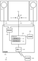
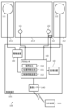
- FIG. 1 is a diagram showing the device configuration and functional configuration of an audio signal reproducing device 100 according to the first embodiment.
- the audio signal reproducing device 100 acquires an audio signal from a terminal device 300, which is an external device of the audio signal reproducing device 100, and vibrates an attached member, which is one of the attached members, based on the acquired audio signal, thereby generating an audio signal.
- This is a device that plays back .
- the audio signal reproducing device 100 includes a first vibration generator 111 and a second vibration generator 112 that are vibration generators, a first vibration sensor 121 that is a vibration sensor, and a second vibration sensor 122, a drive device 130, a communication interface 140, a processor 150, and a storage device 160.
- the drive device 130, the communication interface 140, the processor 150, and the storage device 160 are realized on one chip using so-called SoC (System on a Chip) technology, and constitute the control device 101.
- SoC System on a Chip
- a vibration generator is an actuator that vibrates an attached member to generate sound from the attached member.
- the audio signal reproducing device 100 includes a first vibration generator 111 and a second vibration generator 112, each of which is independently driven as a vibration generator to support stereo reproduction.
- the types of vibration generators are not particularly limited, and include those that drive a voice coil to generate vibrations corresponding to audio signals, and those that drive piezoelectric elements to generate vibrations that correspond to audio signals.
- a vibration generator may be referred to as an audio exciter, audio actuator, vibration speaker, or the like.
- the member to which the vibration generator is attached is not particularly limited, but a relatively hard plate-like member is suitable. Specifically, furniture, building materials, vehicle parts, etc. can be exemplified.
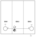
- the attached member is the first attached member 211 of the three mirrors arranged side by side in the left-right direction on the washstand, the mirror arranged at one end is the first attached member 211, and the mirror arranged at the other end is The arranged mirror functions as the second attached member 212.
- the first vibration generator 111 is attached to the back side of the first attached member 211 and generates sound via the first attached member 211.
- the second vibration generator 112 is attached to the back side of the second attached member 212 and generates sound via the second attached member 212.
- the first attached member 211 and the second attached member 212 are each attached to a washbasin body (not shown) via a hinge (not shown).
- the vibration of the first attached member 211 generated by the first vibration generator 111 hardly reaches the second attached member 212, and the vibration of the second attached member 212 generated by the second vibration generator 112 hardly reaches the first attached member 211.
- a vibration sensor is a sensor that detects vibrations of an attached member.
- the audio signal reproducing device 100 uses omnidirectional sensors that independently detect vibrations in order to detect the approximate position where the user knocks on the attached member to which the vibration sensor is attached. It includes a first vibration sensor 121 and a non-directional second vibration sensor 122. A specific detection method will be described later.
- the type of vibration sensor is not particularly limited, and examples include acceleration sensors using strain gauges.
- the processor 150 generates position information based on the difference in arrival time of vibrations generated by user operations, so the length of the signal line from the first vibration sensor 121 to the processor 150, Preferably, the length of the signal line from the second vibration sensor 122 to the processor 150 is substantially the same. This makes it possible to generate position information with high accuracy.
- the attachment target member to which the vibration sensor is attached is not particularly limited, but a relatively hard plate-like member through which vibrations can easily propagate is suitable, similar to the attachment target member to which the vibration generator is attached. .
- the mirror arranged in the center functions as the third member to be mounted 213.
- the first vibration sensor 121 and the second vibration sensor 122 are respectively attached to the lower sides of both ends in the left and right direction on the back side of the third attached member 213, and detect vibrations generated in the third attached member 213, respectively.
- the third attached member 213 is attached to the washbasin body (not shown) via a hinge (not shown). The vibrations generated by the first vibration generator 111 and the second vibration generator 112 hardly reach the third attached member 213.
- the drive device 130 drives the vibration generator and outputs an audio signal that vibrates the attached member and generates sound.
- the drive device 130 amplifies and outputs the two-channel audio signal decoded by the processor 150 so as to correspond to each of the first vibration generator 111 and the second vibration generator 112.
- the communication interface 140 transmits and receives signals to and from the terminal device 300 through at least one of wireless communication and wired communication.
- the communication interface 140 conforms to the Bluetooth (registered trademark) communication standard, and performs P2P (Peer-to-Peer) communication with the terminal device 300 that has been paired in advance. : peer-to-peer) communication.
- the communication interface 140 receives, for example, an audio signal from the terminal device 300 and transmits control information to the terminal device 300.
- the processor 150 is a processing device that performs calculations and conversion of data, executes programs, controls other devices, and the like. In the case of this embodiment, processor 150 executes a program stored in storage device 160, and executes the processing described below.
- the first vibration sensor 121 and the second vibration sensor 122 detect vibrations generated when the user performs an operation such as knocking, tapping, or hitting the third attached member 213 and outputs a signal. Based on these signals, the processor 150 generates position information indicating the position operated by the user on the third attached member 213. Specifically, the processor 150 generates position information based on at least one of a difference in amplitude information, a difference in time information, and a difference in transient information obtained from the first vibration sensor 121 and the second vibration sensor 122. is generated. At this stage, the processor 150 is functioning as the position information generating section 151 by executing the program.
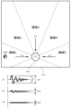
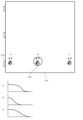
- FIG. 2 is a diagram showing an example 1 of a user's operation on the third attached member 213.
- FIG. 3 is a diagram showing the detection results of vibrations generated by user operations.
- FIG. 4 is a diagram illustrating a second example of a user's operation on the third attached member 213.
- FIG. 5 is a diagram showing a third example of the user's operation on the third attached member 213.
- the processor 150 receives an audio signal from the terminal device 300 via the communication interface 140, and the driving device 130 drives the first vibration generator 111 and the second vibration generator 112 based on the received audio signal. It is assumed that audio is being reproduced from the first attached member 211 and the second attached member 212. In this state, when the user knocks (hits or taps) the surface of the third attached member 213 once as shown in FIG. 2, the first vibration sensor 121 detects the signal shown in the upper part of FIG. The second vibration sensor 122 detects the signal shown in the lower part of FIG. The processor 150 acquires signals detected from the first vibration sensor 121 and the second vibration sensor 122, respectively.
- the processor 150 cannot obtain the time t0 of the knock, but the time t1 when the first vibration sensor 121 detects the vibration, and the second vibration sensor 122 can obtain the time t2 when the vibration was detected.
- T becomes zero.
- time t2 becomes larger than time t1
- T becomes negative according to equation (1).
- the time is equal to or greater than a first time threshold (negative value) predetermined for separating region 1 and region 2.
- time t2 becomes smaller than time t1, and T becomes positive according to equation (1). However, it is less than a second time threshold (positive value) predetermined for separating region 2 and region 3.
- the first time threshold and the second time threshold are stored in the storage device 160, and are called by the processor 150 when generating position information.
- time t2 becomes larger than time t1, and according to equation (1), T becomes a negative value that is less than or equal to the first time threshold.
- time t2 becomes smaller than time t1, and according to equation (1), T becomes a positive value equal to or greater than the second time threshold.
- the processor 150 determines that the knocked position is region 1 (see FIG. 2) when T is less than the first time threshold, and determines that the knocked position is region 1 (see FIG. 2) when T is greater than or equal to the first time threshold and less than the second time threshold. is region 2, and if T is greater than or equal to the second time threshold, position information is generated that indicates that the knocked position is region 3. Note that the first time threshold value ⁇ 0 ⁇ the second time threshold value.
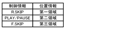
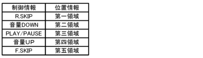
- FIG. 6 is a diagram showing example 1 of relational information.
- processor 150 transmits control information to terminal device 300 via communication interface 140 based on the generated position information.
- the storage device 160 stores relationship information that is a table showing the relationship between position information and control information, as shown in FIG.
- the position information is information generated previously, and the control information is information sent to the terminal device 300.
- the processor 150 generates position information indicating the second area by the user knocking at a midpoint between the first vibration sensor 121 and the second vibration sensor 122
- the processor 150 generates position information indicating the second area based on the relationship information.
- PLAY/PAUSE is transmitted as control information to the terminal device 300 via the communication interface 140.
- the processor 150 is functioning as the control information transmitter 152.
- the terminal device 300 that has acquired the control information executes an operation corresponding to the control information. For example, assume that the audio signal reproducing device 100 outputs PLAY/PAUSE as control information.
- the terminal device 300 that has acquired the control information starts playing the music content if it is not playing the music content (pauses it), and temporarily stops playing the music content if it is playing the music content. Stop.
- an audio signal is reproduced for the user by the vibration generator attached to the back side of the mirror provided in the washstand.
- two vibration sensors attached to the back of the mirror placed in the center perform different controls on the terminal device 300 that is outputting the audio signal. becomes possible.
- the processor 150 transmits control information to the terminal device 300, which is an external device, and the processor 150, which receives the audio signal generated based on the control information received by the terminal device 300, controls the drive device and
- the sound signal reproducing device 100 can generate sound by driving the vibration generator 111 and the second vibration generator 112, and the audio signal reproducing device 100 can reproduce the sound without impairing the design of the washbasin, and can control the terminal device. It becomes possible to accept.
- Embodiment 2 Next, embodiments of an audio signal reproducing device, a method of controlling the audio signal reproducing device, and a control program for the audio signal reproducing device will be described. Note that parts (portions) having the same functions, functions, shapes, mechanisms, and structures as those of the first embodiment are designated by the same reference numerals, and the description thereof may be omitted. Further, in the following, points different from Embodiment 1 will be mainly explained, and explanations of the same contents may be omitted.
- FIG. 7 is a diagram showing the device configuration and functional configuration of the audio signal reproducing device 100 according to the second embodiment.
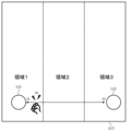
- the first vibration generator 111, the second vibration generator 112, the first vibration sensor 121, and the second vibration sensor 122 are attached to one attached member 210.
- the type of attached member 210 is not particularly limited. For example, a large mirror attached to the wall of a washroom, a wall of a bath (such as a unit bath), a ceiling of a bath, a door of a bath, a table, a desk, etc. can be exemplified.
- the processor 150 reduces the audio signal component from the signal acquired from the vibration sensor before generating position information. That is, the processor 150 functions as the audio signal reduction unit 153 by executing the program. This is because the vibration generator and the vibration sensor are attached to one attached member 210, so the vibration sensor detects the vibration of the attached member 210 caused by the vibration generator, and the user knocks on the attached member 210. This is because there is a possibility that the actual vibrations will be buried in the vibrations based on the audio signal.
- FIG. 8 is a diagram showing the flow of audio signal reduction processing.
- the processor 150 acquires audio signals for driving the first vibration generator 111 and the second vibration generator 112, respectively, by the driving device 130, and acquires inverse audio signals with opposite phases in almost real time. Generates signals. Furthermore, the processor 150 adjusts the amplitude of the generated reverse audio signal to match the amplitude of the vibration based on the audio signal detected by the first vibration sensor 121 and the second vibration sensor 122. The processor 150 causes the reverse audio signal to act on the reverse audio signal whose amplitude has been adjusted and the detection signals detected by the first vibration sensor 121 and the second vibration sensor 122, respectively, to extract the components of the audio signal from the detection signal. Make a reduction.
- the audio signal on which the reverse audio signal is generated is not only obtained from the output of the driving device 130 but also a decoded audio signal input to the driving device 130 or an audio signal acquired from the terminal device 300. It doesn't matter if it's a signal.
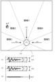
- FIG. 9 is a diagram showing the detection results of vibrations generated by user operations.
- the maximum amplitude w2 becomes larger than the maximum amplitude w1, and W becomes positive according to equation (2). However, it is less than a second amplitude threshold (a positive value) predetermined for separating region 2 and region 3.
- a second amplitude threshold (a positive value) predetermined for separating region 2 and region 3. Note that the first amplitude threshold and the second amplitude threshold are stored in the storage device 160, and are called by the processor 150 when generating position information.
- the processor 150 determines that the knocked position is region 1 (see FIG. 2) when W is less than the first amplitude threshold, and determines that the knocked position is region 1 (see FIG. 2) when W is greater than or equal to the first amplitude threshold and less than the second amplitude threshold. is in region 2, and when W is greater than or equal to the second amplitude threshold, position information is generated that indicates that the knocked position is in region 3. Note that the first amplitude threshold value ⁇ 0 ⁇ the second amplitude threshold value.
- the next transmission of control information by processor 150 is the same as in the first embodiment.
- the same effects as the audio signal reproducing device 100 according to the first embodiment can be achieved. Furthermore, even when the vibration generator and the vibration sensor are attached to the same mounted member 210 and the vibration sensor detects vibrations based on audio signals, the vibration caused by the user's knock can be correctly extracted and position information can be generated correctly. It becomes possible to do so.
- Embodiment 3 Next, embodiments of an audio signal reproducing device, a method of controlling the audio signal reproducing device, and a control program for the audio signal reproducing device will be described. Note that parts (portions) having the same functions, functions, shapes, mechanisms, and structures as those in Embodiments 1 and 2 are designated by the same reference numerals, and the description thereof may be omitted. In addition, the following description will focus on the points that are different from Embodiments 1 and 2, and the description of the same contents may be omitted.
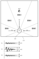
- FIG. 10 is a diagram showing the device configuration and functional configuration of the audio signal reproducing device 100 according to the third embodiment.
- one vibration sensor 120 is attached to the third attached member 213.
- the vibration sensor 120 has a plurality of directivities (in the case of this embodiment, three directions D1, D2, and D3) that strongly detect signals arriving from the directions indicated by arrows in FIG.
- the vibration sensor 120 with directivity is a vibration sensor 120 having a characteristic that the detection sensitivity is high for vibrations coming from a specific direction, and the detection sensitivity decreases when the vibrations deviate from the specific direction.
- the processor 150 generates position information based on amplitude information indicating the strength of vibration obtained from the vibration sensor 120 with directivity in three directions.
- FIG. 11 is a diagram showing example 4 of the user's operation on the third attached member 213.
- FIG. 12 is a diagram showing example 5 of the user's operation on the third attached member 213.
- FIG. 13 is a diagram showing example 6 of the user's operation on the third attached member 213.
- the method by which processor 150 generates position information based on the signal acquired from vibration sensor 120 is not particularly limited. In the case of this embodiment, when the user knocks in area 1, processor 150 obtains a signal from direction D1, a signal from direction D2, and a signal from direction D3, as shown in the graph of FIG. . The processor 150 derives the maximum amplitudes wd1, wd2, wd3 of the three acquired signals.
- the processor 150 If the maximum amplitudes wd1, wd2, and wd3 are greater than or equal to a predetermined first pointing threshold Th1 (wd1), the processor 150 generates position information indicating that area 1 has been knocked. The judgment made by the processor 150 is the same when knocking on area 3 and when knocking on area 5 shown in FIG. 13 (not shown).
- the processor 150 When the user knocks in area 2, the processor 150 obtains a signal from direction D1, a signal from direction D2, and a signal from direction D3, as shown in the graph of FIG. The processor 150 derives the maximum amplitudes wd1, wd2, wd3 of the three acquired signals. If there are no maximum amplitudes wd1, wd2, and wd3 that are equal to or higher than a predetermined first orientation threshold Th1, and there are two maximum amplitudes that are equal to or higher than a second orientation threshold th2 (wd1, wd2), the processor 150 selects the region 2 Generates location information indicating that the person has knocked. This judgment by the processor 150 is the same when knocking in area 4 (not shown).
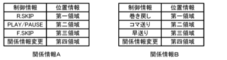
- FIG. 14 is a diagram showing example 2 of relational information.
- Processor 150 transmits control information to terminal device 300 via communication interface 140 based on the generated position information.
- the storage device 160 stores relationship information that is a table showing the relationship between position information and control information, as shown in FIG. For example, when the processor 150 generates position information indicating the second area by the user knocking on the upper left diagonal (area 2) of the vibration sensor 120, the processor 150 generates the volume control information as control information based on the related information. DOWN is sent to drive device 130 without going through communication interface 140.
- the drive device 130 that has acquired the volume DOWN signal lowers the amplification factor of the audio signal compared to the current level.
- the same effects as the audio signal reproducing device 100 according to the first embodiment can be achieved. Further, by using a vibration sensor with directivity, it becomes possible to output a lot of different control information even with one vibration sensor.
- Embodiment 4 Next, embodiments of an audio signal reproducing device, a method of controlling the audio signal reproducing device, and a control program for the audio signal reproducing device will be described. Note that parts (portions) having the same functions, functions, shapes, mechanisms, and structures as those in Embodiments 1, 2, and 3 will be denoted by the same reference numerals, and the description thereof may be omitted. In addition, the following description will focus on the points that are different from Embodiments 1, 2, and 3, and the description of the same contents may be omitted.
- FIG. 15 is a diagram showing the device configuration and functional configuration of the audio signal reproducing device 100 according to the fourth embodiment.
- the first vibration generator 111 is attached to the first attached member 211
- the second vibration generator 112 is attached to the second attached member 212
- the first vibration sensor 121 and the second vibration sensor 122 are respectively attached to the third attached member 213.
- a motion detection sensor 123 that detects the motion of the third attached member 213 is attached to the third attached member 213 to which the first vibration sensor 121 and the second vibration sensor 122 are attached.
- the motion detection sensor 123 detects the motion of the attached member to which the vibration sensor is attached.
- the type of motion detection sensor 123 is not particularly limited.
- the motion detection sensor 123 may be a sensor that detects whether the mirror is in an open or closed state.
- the motion detection sensor 123 includes a microswitch that detects the closed position of the mirror, an illuminance sensor that detects the difference in brightness on the back side of the mirror when the mirror is opened and closed, and a washbasin that maintains the mirror in the closed state.
- An example of this is a magnetic sensor that detects whether or not the object is close to a magnet attached to the object.
- a vibration sensor for movement detection may be provided in addition to the vibration sensor for detecting a knock by the user.
- at least one of the vibration sensors for knock detection may function as the motion detection sensor 123.
- the processor 150 processes the signal from the vibration sensor when the attached member moves based on the signal acquired from the motion detection sensor 123. Specifically, the processor 150 performs a process of not accepting signals from the first vibration sensor 121 and the second vibration sensor 122 while detecting that the third attached member 213 is in the open state. Let's do it. Therefore, processor 150 does not generate location information or send control information.
- the same effects as the audio signal reproducing device 100 according to the first embodiment can be achieved.
- the motion detection sensor 123 prevents malfunction by not accepting signals from the vibration sensor even if an event similar to a knock by the user occurs in an unstable state where the third attached member 213 is not closed. It becomes possible to do so.
- the present disclosure is not limited to the above embodiments.
- other embodiments of the present disclosure may be implemented by arbitrarily combining the components described in this specification or by excluding some of the components.
- the present disclosure also includes modifications obtained by making various modifications to the above-described embodiments that a person skilled in the art can think of without departing from the gist of the present disclosure, that is, the meaning indicated by the words described in the claims. It will be done.
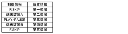
- the processor 150 controls the communication interface 140 based on the position information to perform wireless communication. You may also switch the terminal device 300 that is used. Specifically, as in Example 3 of relational information shown in FIG. 16, the paired terminal devices A and B are associated with predetermined position information as control information.
- the communication interface 140 is in a state where it can be connected to the terminal device A. In this state, when the user knocks on area 4 of the attached member to which the vibration sensor is attached, the processor 150 generates position information for the fourth area and connects the terminal device B corresponding to the fourth area. You may change the settings of the communication interface 140 so that it is possible.
- the storage device 160 may include a plurality of different types of relationship information, and the processor 150 may change the relationship information based on the generated position information. For example, as shown in FIG. 17, the storage device 160 stores relationship information A and relationship information B. The processor 150 transmits control information based on the relationship information A. When the user knocks on the fourth area, the processor 150 reads the related information B from the storage device 160 and changes the related information A to the related information B. As a result, it is possible to transmit more types of control information than can identify the position of the user's knock, and it becomes possible to perform many types of control.
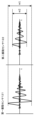
- Position information may be generated using transient information indicating transient characteristics.
- the transient information is, for example, information indicating a decreasing tendency of amplitude. Specifically, as shown in FIG. 18, when the attached member 210 is a plate-shaped member attached via a hinge 219, the amplitude tends to decrease when the user knocks at position A near the hinge 219.
- the processor 150 generates the position information based on the fact that the decreasing tendency of the amplitude when knocking at the position C that is farthest from the hinge is different from the decreasing tendency of the amplitude when knocking at the position B that is directly above the vibration sensor 120. You may go.
- the processor 150 may generate position information by combining these pieces of information. do not have.
- a filter circuit that filters the signal detected by the vibration sensor may be interposed between the vibration sensor and the processor 150, or the processor 150 may perform the filtering.
- the filter include a high-pass filter, a low-pass filter, and a band-pass filter.
- an element capable of filtering such as a DSP (Digital Signal Processor), may be placed in the control device 101 on the same chip as the processor 150 and the like.
- DSP Digital Signal Processor
- the filter characteristics may be determined in advance, and the filter characteristics may be set by performing calibration as an initial setting after the audio signal reproducing device 100 is attached to the mounting member. It doesn't matter.
- a test signal (a wide band signal such as a sweep signal) is sent to a vibration generator to generate vibrations on the attached member, and the vibrations are detected by a vibration sensor.
- the characteristics of the filter may be set based on the difference between the test signal and the detected signal (test signal - detection signal).
- the processor 150 may detect the number of times the user knocks on the attached member continuously, and generates the number of times information.
- the processor 150 may obtain relational information corresponding to the number of times information from a plurality of types of relational information stored in the storage device 160, and output control information corresponding to the positional information based on this.
- the audio signal reproducing device 100 may accept changes in settings, the type of related information to be used, etc. from the connected terminal device 300.
- the processor 150 generates position information using the difference in time information, but in the first embodiment, the processor 150 generates position information using the difference in time information, the difference in amplitude information, and the difference in transient information. Position information may be generated using at least one of the differences.
- the processor 150 generates position information using the difference in amplitude information, but in the second embodiment, the processor 150 generates position information using the difference in time information, the difference in amplitude information, and the difference in transient information.
- the position information may be generated using at least one of the following.
- the processor 150 generates position information using the difference in amplitude information, but in the third embodiment, the processor 150 generates the position information using the difference in time information, the difference in amplitude information, and the difference in transient information.
- the position information may be generated using at least one of the following.
- the types of information on which the processor 150 generates position information are not specified, but in the fourth embodiment, the processor 150 can detect differences in time information, differences in amplitude information, and Position information may be generated using at least one of the differences in transient information.
- the motion detection sensor 123 is attached to the attached member, and the processor 150 collects the signal from the vibration sensor when the attached member performs an opening/closing operation based on the signal acquired from the motion detection sensor 123.
- the audio signal reproducing device 100 may include a motion detection sensor 123 attached to a member to be attached.
- the processor 150 included in the audio signal reproducing device 100 may process the signal from the vibration sensor when the attached member moves based on the signal acquired from the motion detection sensor 123.
- the present disclosure is applicable to a device that reproduces an audio signal by vibrating an attached member.
- Audio signal reproducing device 101 Control device 111 First vibration generator 112 Second vibration generator 120 Vibration sensor 121 First vibration sensor 122 Second vibration sensor 123 Motion detection sensor 130 Drive device 140 Communication interface 150 Processor 160 Storage device 210 Attachment member 211 First attached member 212 Second attached member 213 Third attached member 219 Hinge 300 Terminal device
Abstract
A sound signal reproduction device (100) comprising a first vibration generator (111) and a second vibration generator (112) that are respectively attached to a first attachment mating member (211) and a second attachment mating member (212), a first vibration sensor (121) and a second vibration sensor (122) that are attached to a third attachment mating member (213), a drive device (130) that drives the vibration generators, a processor (150), and a storage device (160) that stores a program. The sound signal reproduction device (100): generates, on the basis of signals acquired from the vibration sensors, position information indicating the position of vibration that a user has caused to be generated in the third attachment mating member (213) to which the vibration sensors are attached; and transmits control information on the basis of the position information.
Description
本開示は、音声信号再生装置、音声信号再生装置の制御方法、および音声信号再生装置の制御プログラムに関する。
The present disclosure relates to an audio signal reproducing device, a method of controlling the audio signal reproducing device, and a control program for the audio signal reproducing device.
特許文献1には、鏡を強制的に振動させ、鏡から音声を発生させるスピーカーユニットが風呂の鏡に取り付けられる技術が記載されている。また、スピーカーユニットを制御するために、鏡の表面にタッチセンサを設ける技術も特許文献1には記載されている。
Patent Document 1 describes a technology in which a speaker unit that forcibly vibrates the mirror and generates sound from the mirror is attached to a bathroom mirror. Patent Document 1 also describes a technique in which a touch sensor is provided on the surface of a mirror in order to control the speaker unit.
本開示は、音声再生に関する制御などを行うことができる音声信号再生装置、音声信号再生装置の制御方法、および音声信号再生装置の制御プログラムを提供する。
The present disclosure provides an audio signal reproducing device, a method for controlling the audio signal reproducing device, and a control program for the audio signal reproducing device, which can control audio reproduction.
本開示における音声信号再生装置は、1または複数の被取付部材に取り付けられる振動発生器と、前記振動発生器が取り付けられる前記被取付部材、または前記振動発生器が取り付けられる前記被取付部材とは別体の被取付部材に取り付けられる振動センサと、音声信号に基づき前記振動発生器を駆動し、前記被取付部材を介して音を発生させる駆動装置と、プログラムを実行するプロセッサと、前記プロセッサに実行させるプログラムを記憶する記憶装置と、を備え、前記プロセッサに前記プログラムを実行させることにより、前記振動センサから取得した信号に基づき前記振動センサが取り付けられた前記被取付部材にユーザーが発生させた振動の位置を示す位置情報の生成を行い、前記位置情報に基づいて制御情報の送信を行う。
The audio signal reproducing device according to the present disclosure includes a vibration generator attached to one or more attached members, the attached member to which the vibration generator is attached, or the attached member to which the vibration generator is attached. a vibration sensor attached to a separate attached member; a drive device that drives the vibration generator based on an audio signal to generate sound via the attached member; a processor that executes a program; a storage device that stores a program to be executed, and by causing the processor to execute the program, a user generates a vibration on the attached member to which the vibration sensor is attached based on a signal acquired from the vibration sensor. Position information indicating the position of vibration is generated, and control information is transmitted based on the position information.
本開示によれば、振動センサが取り付けられた被取付部材においてユーザーが振動を発生させた位置に応じて、音声再生に関する制御などを行うことができる。
According to the present disclosure, it is possible to control audio playback, etc., depending on the position where the user generates vibration on the attached member to which the vibration sensor is attached.
以下、本開示に係る音声信号再生装置、音声信号再生装置の制御方法、および音声信号再生装置の制御プログラムの実施の形態について、図面を参照しつつ説明する。なお、以下の実施の形態は、本開示を説明するために一例を挙示するものであり、本開示を限定する主旨ではない。例えば、以下の実施の形態において示される形状、構造、材料、構成要素、相対的位置関係、接続状態、数値、数式、方法における各段階の内容、各段階の順序などは、一例であり、以下に記載されていない内容を含む場合がある。また、平行、直交などの幾何学的な表現を用いる場合があるが、これらの表現は、数学的な厳密さを示すものではなく、実質的に許容される誤差、ずれなどが含まれる。また、同時、同一などの表現も、実質的に許容される範囲を含んでいる。
Hereinafter, embodiments of an audio signal reproducing device, a method of controlling the audio signal reproducing device, and a control program for the audio signal reproducing device according to the present disclosure will be described with reference to the drawings. Note that the following embodiments are provided as examples to explain the present disclosure, and are not intended to limit the present disclosure. For example, the shapes, structures, materials, components, relative positional relationships, connection states, numerical values, formulas, contents of each step in the method, order of each step, etc. shown in the following embodiments are merely examples. It may contain content not listed. Furthermore, although geometric expressions such as parallel and perpendicular are sometimes used, these expressions do not indicate mathematical rigor and include substantially permissible errors, deviations, and the like. Furthermore, expressions such as "simultaneously" and "identical" also include a substantially permissible range.
また、図面は、本開示を説明するために適宜強調、省略、または比率の調整を行った模式的な図となっており、実際の形状、位置関係、および比率とは異なる。また、図中に示す場合があるX軸、Y軸、Z軸は、図の説明のために任意に設定した直交座標を示している。つまりZ軸は、鉛直方向に沿う軸とは限らず、X軸、Y軸は、水平面内に存在するとは限らない。
In addition, the drawings are schematic diagrams with emphasis, omission, or ratio adjustment as appropriate for explaining the present disclosure, and the actual shapes, positional relationships, and ratios differ. Further, the X-axis, Y-axis, and Z-axis that may be shown in the drawings indicate orthogonal coordinates arbitrarily set for the purpose of explaining the drawings. In other words, the Z-axis is not necessarily an axis along the vertical direction, and the X-axis and Y-axis are not necessarily in a horizontal plane.
また、以下では複数の発明を一つの実施の形態として包括的に説明する場合がある。また、以下に記載する内容の一部は、本開示に関する任意の構成要素として説明している。
Further, below, multiple inventions may be comprehensively described as one embodiment. Further, some of the contents described below are described as optional components related to the present disclosure.
(実施の形態1)
図1は、実施の形態1に係る音声信号再生装置100の装置構成、および機能構成を示す図である。音声信号再生装置100は、音声信号再生装置100の外部機器である端末装置300から音声信号を取得し、取得した音声信号に基づき被取付部材の一つである被取付部材を振動させて音声信号を再生する装置である。 (Embodiment 1)
FIG. 1 is a diagram showing the device configuration and functional configuration of an audiosignal reproducing device 100 according to the first embodiment. The audio signal reproducing device 100 acquires an audio signal from a terminal device 300, which is an external device of the audio signal reproducing device 100, and vibrates an attached member, which is one of the attached members, based on the acquired audio signal, thereby generating an audio signal. This is a device that plays back .
図1は、実施の形態1に係る音声信号再生装置100の装置構成、および機能構成を示す図である。音声信号再生装置100は、音声信号再生装置100の外部機器である端末装置300から音声信号を取得し、取得した音声信号に基づき被取付部材の一つである被取付部材を振動させて音声信号を再生する装置である。 (Embodiment 1)
FIG. 1 is a diagram showing the device configuration and functional configuration of an audio
本実施の形態の場合、音声信号再生装置100は、振動発生器である第一振動発生器111、および第二振動発生器112と、振動センサである第一振動センサ121、および第二振動センサ122と、駆動装置130と、通信インターフェース140と、プロセッサ150と、記憶装置160と、を備えている。駆動装置130、通信インターフェース140、プロセッサ150、および記憶装置160は、いわゆるSoC(System on a chip)技術によりワンチップ上に実現され、制御装置101を構成している。なお、本実施の形態の場合、ワンチップ上に実現される制御装置101を例示的に説明するが、本開示は、これに限定されるものではない。
In the case of the present embodiment, the audio signal reproducing device 100 includes a first vibration generator 111 and a second vibration generator 112 that are vibration generators, a first vibration sensor 121 that is a vibration sensor, and a second vibration sensor 122, a drive device 130, a communication interface 140, a processor 150, and a storage device 160. The drive device 130, the communication interface 140, the processor 150, and the storage device 160 are realized on one chip using so-called SoC (System on a Chip) technology, and constitute the control device 101. Note that in the case of this embodiment, the control device 101 implemented on one chip will be described as an example, but the present disclosure is not limited thereto.
振動発生器は、取り付けられた被取付部材を振動させ、被取付部材から音を発生させるアクチュエータである。本実施の形態の場合、音声信号再生装置100は、ステレオ再生に対応するよう振動発生器としてそれぞれ独立して駆動する第一振動発生器111、および第二振動発生器112を備えている。振動発生器の種類は、特に限定されるものではなく、ボイスコイルを駆動させて音声信号に対応する振動を発生させるもの、圧電(ピエゾ)素子を駆動させて音声に対応する振動を発生させるものなどを例示することができる。振動発生器は、オーディオエキサイタ、オーディオアクチュエータ、振動スピーカ等と称される場合がある。
A vibration generator is an actuator that vibrates an attached member to generate sound from the attached member. In the case of the present embodiment, the audio signal reproducing device 100 includes a first vibration generator 111 and a second vibration generator 112, each of which is independently driven as a vibration generator to support stereo reproduction. The types of vibration generators are not particularly limited, and include those that drive a voice coil to generate vibrations corresponding to audio signals, and those that drive piezoelectric elements to generate vibrations that correspond to audio signals. For example, A vibration generator may be referred to as an audio exciter, audio actuator, vibration speaker, or the like.
振動発生器の取り付け先である被取付部材は、特に限定されるものではないが、比較的硬質の板状の部材が適している。具体的には、家具、建材、車両用部材などを例示することができる。本実施の形態の場合、被取付部材は、洗面台に左右方向に並べて配置される三つの鏡のうち、一方の端部に配置される鏡が第一被取付部材211、他方の端部に配置される鏡が第二被取付部材212として機能している。第一振動発生器111は、第一被取付部材211の裏側に取り付けられ、第一被取付部材211を介して音を発生させる。第二振動発生器112は、第二被取付部材212の裏側に取り付けられ、第二被取付部材212を介して音を発生させる。第一被取付部材211、および第二被取付部材212は、それぞれヒンジ(不図示)を介して洗面台本体(不図示)に取り付けられている。第一振動発生器111により発生する第一被取付部材211の振動は、第二被取付部材212にはほとんど到達せず、また第二振動発生器112により発生する第二被取付部材212の振動は第一被取付部材211にはほとんど到達しない。
The member to which the vibration generator is attached is not particularly limited, but a relatively hard plate-like member is suitable. Specifically, furniture, building materials, vehicle parts, etc. can be exemplified. In the case of this embodiment, the attached member is the first attached member 211 of the three mirrors arranged side by side in the left-right direction on the washstand, the mirror arranged at one end is the first attached member 211, and the mirror arranged at the other end is The arranged mirror functions as the second attached member 212. The first vibration generator 111 is attached to the back side of the first attached member 211 and generates sound via the first attached member 211. The second vibration generator 112 is attached to the back side of the second attached member 212 and generates sound via the second attached member 212. The first attached member 211 and the second attached member 212 are each attached to a washbasin body (not shown) via a hinge (not shown). The vibration of the first attached member 211 generated by the first vibration generator 111 hardly reaches the second attached member 212, and the vibration of the second attached member 212 generated by the second vibration generator 112 hardly reaches the first attached member 211.
振動センサは、取り付けられた被取付部材の振動を検出するセンサである。本実施の形態の場合、音声信号再生装置100は、振動センサが取り付けられた被取付部材をユーザーがノックしたおおよその位置を検出するため、それぞれ独立して振動を検出するする無指向性の第一振動センサ121、および無指向性の第二振動センサ122を備えている。具体的な検出方法は、後述する。振動センサの種類は、特に限定されるものではなく、ひずみゲージを用いた加速度センサなどを例示することができる。なお、本実施の形態の場合、プロセッサ150は、ユーザーの操作により発生した振動の到達時刻の差によって位置情報の生成を行うため、第一振動センサ121からプロセッサ150までの信号線の長さと、第二振動センサ122からプロセッサ150までの信号線の長さとは実質的に同じ長さであることが好ましい。これにより高い精度で位置情報の生成を行うことが可能となる。
A vibration sensor is a sensor that detects vibrations of an attached member. In the case of the present embodiment, the audio signal reproducing device 100 uses omnidirectional sensors that independently detect vibrations in order to detect the approximate position where the user knocks on the attached member to which the vibration sensor is attached. It includes a first vibration sensor 121 and a non-directional second vibration sensor 122. A specific detection method will be described later. The type of vibration sensor is not particularly limited, and examples include acceleration sensors using strain gauges. Note that in the case of this embodiment, the processor 150 generates position information based on the difference in arrival time of vibrations generated by user operations, so the length of the signal line from the first vibration sensor 121 to the processor 150, Preferably, the length of the signal line from the second vibration sensor 122 to the processor 150 is substantially the same. This makes it possible to generate position information with high accuracy.
振動センサの取り付け先である被取付部材は、特に限定されるものではないが、振動発生器が取り付けられる被取付部材と同様、振動が伝播し易い比較的硬質の板状の部材が適している。本実施の形態の場合、被取付部材は、洗面台に左右方向に並べて配置される三つの鏡のうち、中央に配置される鏡が第三被取付部材213として機能している。第一振動センサ121、および第二振動センサ122は、第三被取付部材213の裏側の左右方向両端部の下側にそれぞれ取り付けられ、第三被取付部材213に発生した振動をそれぞれ検出する。第三被取付部材213は、ヒンジ(不図示)を介して洗面台本体(不図示)に取り付けられている。第一振動発生器111、および第二振動発生器112により発生する振動は、第三被取付部材213にはほとんど到達しない。
The attachment target member to which the vibration sensor is attached is not particularly limited, but a relatively hard plate-like member through which vibrations can easily propagate is suitable, similar to the attachment target member to which the vibration generator is attached. . In the case of this embodiment, among the three mirrors arranged side by side in the left-right direction on the wash basin, the mirror arranged in the center functions as the third member to be mounted 213. The first vibration sensor 121 and the second vibration sensor 122 are respectively attached to the lower sides of both ends in the left and right direction on the back side of the third attached member 213, and detect vibrations generated in the third attached member 213, respectively. The third attached member 213 is attached to the washbasin body (not shown) via a hinge (not shown). The vibrations generated by the first vibration generator 111 and the second vibration generator 112 hardly reach the third attached member 213.
駆動装置130は、振動発生器を駆動し、被取付部材を振動させて音を発生させる音声信号を出力する。本実施の形態の場合、駆動装置130は、プロセッサ150によりデコードされた2チャンネルの音声信号を第一振動発生器111、および第二振動発生器112のそれぞれに対応するよう増幅して出力する。
The drive device 130 drives the vibration generator and outputs an audio signal that vibrates the attached member and generates sound. In the case of this embodiment, the drive device 130 amplifies and outputs the two-channel audio signal decoded by the processor 150 so as to correspond to each of the first vibration generator 111 and the second vibration generator 112.
通信インターフェース140は、端末装置300との間で無線通信、および有線通信の少なくとも一方により信号を送受信する。本実施の形態の場合、通信インターフェース140は、ブルートゥース(登録商標)(Bluetooth:登録商標)通信の規格に適合しており、あらかじめペアリングを行った端末装置300との間でP2P(Peer to Peer:ピア・トゥ・ピア)通信を行うことができる。通信インターフェース140は、例えば端末装置300から音声信号を受信し、端末装置300に制御情報を送信する。
The communication interface 140 transmits and receives signals to and from the terminal device 300 through at least one of wireless communication and wired communication. In the case of the present embodiment, the communication interface 140 conforms to the Bluetooth (registered trademark) communication standard, and performs P2P (Peer-to-Peer) communication with the terminal device 300 that has been paired in advance. : peer-to-peer) communication. The communication interface 140 receives, for example, an audio signal from the terminal device 300 and transmits control information to the terminal device 300.
プロセッサ150は、データの演算や変換、プログラムの実行、他の装置の制御などを行う処理装置である。本実施の形態の場合、プロセッサ150は、記憶装置160に記憶されているプログラムを実行し、次に説明する処理を実行する。
The processor 150 is a processing device that performs calculations and conversion of data, executes programs, controls other devices, and the like. In the case of this embodiment, processor 150 executes a program stored in storage device 160, and executes the processing described below.
ユーザーが第三被取付部材213に対しノックする、タップする、叩くなどの操作をすることにより発生した振動を第一振動センサ121、および第二振動センサ122が検出して信号を出力する。プロセッサ150は、これらの信号に基づき第三被取付部材213にユーザーが操作した位置を示す位置情報の生成を行う。具体的には、プロセッサ150は、第一振動センサ121、および第二振動センサ122から得られる振幅情報の差、時間情報の差、および過渡情報の差のうちの少なくとも1つに基づいて位置情報の生成を行う。この段階においてプロセッサ150は、プログラムを実行することにより位置情報生成部151として機能している。
The first vibration sensor 121 and the second vibration sensor 122 detect vibrations generated when the user performs an operation such as knocking, tapping, or hitting the third attached member 213 and outputs a signal. Based on these signals, the processor 150 generates position information indicating the position operated by the user on the third attached member 213. Specifically, the processor 150 generates position information based on at least one of a difference in amplitude information, a difference in time information, and a difference in transient information obtained from the first vibration sensor 121 and the second vibration sensor 122. is generated. At this stage, the processor 150 is functioning as the position information generating section 151 by executing the program.
図2は、第三被取付部材213へのユーザーの操作の例1を示す図である。図3は、ユーザーの操作により発生した振動の検出結果を示す図である。図4は、第三被取付部材213へのユーザーの操作の例2を示す図である。図5は、第三被取付部材213へのユーザーの操作の例3を示す図である。
FIG. 2 is a diagram showing an example 1 of a user's operation on the third attached member 213. FIG. 3 is a diagram showing the detection results of vibrations generated by user operations. FIG. 4 is a diagram illustrating a second example of a user's operation on the third attached member 213. FIG. 5 is a diagram showing a third example of the user's operation on the third attached member 213.
例えば、端末装置300から通信インターフェース140を介して音声信号をプロセッサ150が受信し、受信した音声信号に基づき駆動装置130が第一振動発生器111、および第二振動発生器112を駆動して第一被取付部材211、および第二被取付部材212から音声が再生されている状態とする。この状態において、図2に示すように第三被取付部材213の表面をユーザーが一回ノックする(叩く、タップする)と、第一振動センサ121では図3の上段に示す信号が検出され、第二振動センサ122では図3の下段に示す信号が検出される。プロセッサ150は、第一振動センサ121、および第二振動センサ122からそれぞれ検出された信号を取得する。本実施の形態の場合、プロセッサ150は、第一振動センサ121、および第二振動センサ122から得られる振幅情報の差、時間情報の差、および過渡情報の差のうち時間情報の差を用いて位置情報の生成を行う。具体的にプロセッサ150は、時間情報として第一振動センサ121から信号を取得した時刻t1と第二振動センサ122から信号を取得した時刻t2との差Tを導出するため、下記式(1)を演算する。
T=t1-t2 (1) For example, theprocessor 150 receives an audio signal from the terminal device 300 via the communication interface 140, and the driving device 130 drives the first vibration generator 111 and the second vibration generator 112 based on the received audio signal. It is assumed that audio is being reproduced from the first attached member 211 and the second attached member 212. In this state, when the user knocks (hits or taps) the surface of the third attached member 213 once as shown in FIG. 2, the first vibration sensor 121 detects the signal shown in the upper part of FIG. The second vibration sensor 122 detects the signal shown in the lower part of FIG. The processor 150 acquires signals detected from the first vibration sensor 121 and the second vibration sensor 122, respectively. In the case of the present embodiment, the processor 150 uses the difference in time information among the difference in amplitude information, the difference in time information, and the difference in transient information obtained from the first vibration sensor 121 and the second vibration sensor 122. Generate location information. Specifically, the processor 150 uses the following equation (1) to derive the difference T between time t1 at which the signal is acquired from the first vibration sensor 121 and time t2 at which the signal is acquired from the second vibration sensor 122 as time information. calculate.
T=t1-t2 (1)
T=t1-t2 (1) For example, the
T=t1-t2 (1)
図2に示すように、ユーザーが領域2においてノックした場合、プロセッサ150は、ノックした時刻t0を取得することはできず、第一振動センサ121が振動を検出した時刻t1、および第二振動センサ122が振動を検出した時刻t2を取得できる。例えば、ユーザーが第一振動センサ121と第二振動センサ122との中間地点をノックした場合、t1、およびt2は、同時刻となる。従って式(1)によりTは、ゼロとなる。領域2内の中間地点より左側をノックした場合、時刻t1より時刻t2は、大きくなり、式(1)によりTは、マイナスとなる。ただし、領域1と領域2とを区分するために予め定められた第一時間閾値(負の値)以上となる。領域2内の中間地点より右側をノックした場合、時刻t1より時刻t2は、小さくなり、式(1)によりTは、プラスとなる。ただし、領域2と領域3とを区分するために予め定められた第二時間閾値(正の値)未満となる。なお、第一時間閾値、および第二時間閾値は、記憶装置160に記憶されており、位置情報の生成を行う際にプロセッサ150に呼び出される。
As shown in FIG. 2, when the user knocks in area 2, the processor 150 cannot obtain the time t0 of the knock, but the time t1 when the first vibration sensor 121 detects the vibration, and the second vibration sensor 122 can obtain the time t2 when the vibration was detected. For example, when the user knocks at a midpoint between the first vibration sensor 121 and the second vibration sensor 122, t1 and t2 are the same time. Therefore, according to equation (1), T becomes zero. When a knock is made on the left side of the intermediate point in region 2, time t2 becomes larger than time t1, and T becomes negative according to equation (1). However, the time is equal to or greater than a first time threshold (negative value) predetermined for separating region 1 and region 2. When a knock is made on the right side of the intermediate point in region 2, time t2 becomes smaller than time t1, and T becomes positive according to equation (1). However, it is less than a second time threshold (positive value) predetermined for separating region 2 and region 3. Note that the first time threshold and the second time threshold are stored in the storage device 160, and are called by the processor 150 when generating position information.
図4に示すように、領域1内においてノックした場合、時刻t1より時刻t2は、大きくなり、式(1)によりTは、第一時間閾値以下のマイナスの値となる。一方、図5に示すように、領域3内においてノックした場合、時刻t1より時刻t2は、小さくなり、式(1)によりTは、第二時間閾値以上のプラスの値となる。
As shown in FIG. 4, when there is a knock in region 1, time t2 becomes larger than time t1, and according to equation (1), T becomes a negative value that is less than or equal to the first time threshold. On the other hand, as shown in FIG. 5, when there is a knock within region 3, time t2 becomes smaller than time t1, and according to equation (1), T becomes a positive value equal to or greater than the second time threshold.
プロセッサ150は、Tが第一時間閾値未満の場合、ノックされた位置が領域1(図2参照)であるとし、Tが第一時間閾値以上、第二時間閾値未満の場合、ノックされた位置が領域2であるとし、Tが第二時間閾値以上の場合、ノックされた位置が領域3であるとする位置情報の生成を行う。なお、第一時間閾値<0<第二時間閾値である。
The processor 150 determines that the knocked position is region 1 (see FIG. 2) when T is less than the first time threshold, and determines that the knocked position is region 1 (see FIG. 2) when T is greater than or equal to the first time threshold and less than the second time threshold. is region 2, and if T is greater than or equal to the second time threshold, position information is generated that indicates that the knocked position is region 3. Note that the first time threshold value<0<the second time threshold value.
図6は、関係情報の例1を示す図である。次に、プロセッサ150は、生成した位置情報に基づき通信インターフェース140を介して端末装置300に制御情報の送信を行う。本実施の形態の場合、記憶装置160は、図6に示す、位置情報と制御情報との関係を示すテーブルである関係情報を記憶している。位置情報は、先に生成した情報であり、制御情報は、端末装置300に送信する情報である。例えば、ユーザーが第一振動センサ121と第二振動センサ122との中間地点をノックすることにより、プロセッサ150が第二領域を示す位置情報の生成を行った場合、プロセッサ150は、関係情報に基づき制御情報としてPLAY/PAUSEを、通信インターフェース140を介して端末装置300に送信する。この段階ではプロセッサ150は、制御情報送信部152として機能している。
FIG. 6 is a diagram showing example 1 of relational information. Next, processor 150 transmits control information to terminal device 300 via communication interface 140 based on the generated position information. In the case of this embodiment, the storage device 160 stores relationship information that is a table showing the relationship between position information and control information, as shown in FIG. The position information is information generated previously, and the control information is information sent to the terminal device 300. For example, if the processor 150 generates position information indicating the second area by the user knocking at a midpoint between the first vibration sensor 121 and the second vibration sensor 122, the processor 150 generates position information indicating the second area based on the relationship information. PLAY/PAUSE is transmitted as control information to the terminal device 300 via the communication interface 140. At this stage, the processor 150 is functioning as the control information transmitter 152.
制御情報を取得した端末装置300は、制御情報に対応した動作を実行する。例えば、音声信号再生装置100が制御情報としてPLAY/PAUSEを出力したとする。当該制御情報を取得した端末装置300は、音楽コンテンツを再生していない(一時停止中である)場合、音楽コンテンツの再生を開始し、音楽コンテンツを再生中である場合、音楽コンテンツの再生を一時停止する。
The terminal device 300 that has acquired the control information executes an operation corresponding to the control information. For example, assume that the audio signal reproducing device 100 outputs PLAY/PAUSE as control information. The terminal device 300 that has acquired the control information starts playing the music content if it is not playing the music content (pauses it), and temporarily stops playing the music content if it is playing the music content. Stop.
上記実施の形態1に係る音声信号再生装置100によれば、洗面台が備える鏡の裏側に取り付けられた振動発生器によりユーザーに対し音声信号を再生する。また、中央に配置された鏡の裏に取り付けられた2つの振動センサにより、ユーザーが中央の鏡をノックする位置を変えることで、音声信号を出力している端末装置300に異なる制御を実行することが可能となる。以上から、プロセッサ150は、制御情報を外部機器である端末装置300に送信し、端末装置300が受信した制御情報に基づいて生成した音声信号を受信したプロセッサ150は駆動装置を制御して第一振動発生器111、および第二振動発生器112を駆動して音を発生させることができ、音声信号再生装置100は、洗面台の意匠性を損ねること無く音声を再生し、端末装置への制御を受け付けることが可能となる。
According to the audio signal reproducing device 100 according to the first embodiment, an audio signal is reproduced for the user by the vibration generator attached to the back side of the mirror provided in the washstand. In addition, by changing the position at which the user knocks on the central mirror, two vibration sensors attached to the back of the mirror placed in the center perform different controls on the terminal device 300 that is outputting the audio signal. becomes possible. From the above, the processor 150 transmits control information to the terminal device 300, which is an external device, and the processor 150, which receives the audio signal generated based on the control information received by the terminal device 300, controls the drive device and The sound signal reproducing device 100 can generate sound by driving the vibration generator 111 and the second vibration generator 112, and the audio signal reproducing device 100 can reproduce the sound without impairing the design of the washbasin, and can control the terminal device. It becomes possible to accept.
(実施の形態2)
続いて、音声信号再生装置、音声信号再生装置の制御方法、および音声信号再生装置の制御プログラムの実施の形態について説明する。なお、前記実施の形態1と同様の作用や機能、同様の形状や機構や構造を有するもの(部分)には同じ符号を付して説明を省略する場合がある。また、以下では実施の形態1と異なる点を中心に説明し、同じ内容については説明を省略する場合がある。 (Embodiment 2)
Next, embodiments of an audio signal reproducing device, a method of controlling the audio signal reproducing device, and a control program for the audio signal reproducing device will be described. Note that parts (portions) having the same functions, functions, shapes, mechanisms, and structures as those of the first embodiment are designated by the same reference numerals, and the description thereof may be omitted. Further, in the following, points different fromEmbodiment 1 will be mainly explained, and explanations of the same contents may be omitted.
続いて、音声信号再生装置、音声信号再生装置の制御方法、および音声信号再生装置の制御プログラムの実施の形態について説明する。なお、前記実施の形態1と同様の作用や機能、同様の形状や機構や構造を有するもの(部分)には同じ符号を付して説明を省略する場合がある。また、以下では実施の形態1と異なる点を中心に説明し、同じ内容については説明を省略する場合がある。 (Embodiment 2)
Next, embodiments of an audio signal reproducing device, a method of controlling the audio signal reproducing device, and a control program for the audio signal reproducing device will be described. Note that parts (portions) having the same functions, functions, shapes, mechanisms, and structures as those of the first embodiment are designated by the same reference numerals, and the description thereof may be omitted. Further, in the following, points different from
図7は、実施の形態2に係る音声信号再生装置100の装置構成、および機能構成を示す図である。本実施の形態の場合、第一振動発生器111、第二振動発生器112、第一振動センサ121、および第二振動センサ122は、1つの被取付部材210に取り付けられている。被取付部材210の種類は、特に限定されるものではない。例えば、洗面所の壁面に取り付けられた大型の鏡、風呂(ユニットバスなど)の壁、風呂の天井、風呂のドア、テーブル、机などを例示することができる。
FIG. 7 is a diagram showing the device configuration and functional configuration of the audio signal reproducing device 100 according to the second embodiment. In the case of this embodiment, the first vibration generator 111, the second vibration generator 112, the first vibration sensor 121, and the second vibration sensor 122 are attached to one attached member 210. The type of attached member 210 is not particularly limited. For example, a large mirror attached to the wall of a washroom, a wall of a bath (such as a unit bath), a ceiling of a bath, a door of a bath, a table, a desk, etc. can be exemplified.
本実施の形態の場合、プロセッサ150は、位置情報の生成を行う前に、振動センサから取得した信号から音声信号の成分の低減を行う。つまり、プロセッサ150は、プログラムを実行することにより音声信号低減部153として機能する。これは、振動発生器、および振動センサが1つの被取付部材210に取り付けられているため、振動発生器による被取付部材210の振動を振動センサが検出し、ユーザーが被取付部材210をノックした際の振動が音声信号に基づく振動に埋もれる可能性があるためである。
In the case of this embodiment, the processor 150 reduces the audio signal component from the signal acquired from the vibration sensor before generating position information. That is, the processor 150 functions as the audio signal reduction unit 153 by executing the program. This is because the vibration generator and the vibration sensor are attached to one attached member 210, so the vibration sensor detects the vibration of the attached member 210 caused by the vibration generator, and the user knocks on the attached member 210. This is because there is a possibility that the actual vibrations will be buried in the vibrations based on the audio signal.
図8は、音声信号の低減処理の流れを示す図である。本実施の形態の場合、具体的にプロセッサ150は、駆動装置130が第一振動発生器111、および第二振動発生器112をそれぞれ駆動する音声信号を取得し、ほぼリアルタイムで逆位相の逆音声信号の生成を行う。また、プロセッサ150は、生成した逆音声信号の振幅を、第一振動センサ121、および第二振動センサ122が検出する音声信号に基づく振動の振幅に合致するように調整を行う。プロセッサ150は、振幅の調整を終えた逆音声信号と第一振動センサ121、および第二振動センサ122がそれぞれ検知した検出信号に逆音声信号を作用させて検出信号の中から音声信号の成分の低減を行う。以上によりユーザーが被取付部材210をノックしたことによる振動を抽出することができる。なお、逆音声信号の生成の基となる音声信号は、駆動装置130の出力から取得する場合ばかりでなく、駆動装置130に入力するデコードされた音声信号、端末装置300から取得した音声信号をデコードした信号などでもかまわない。
FIG. 8 is a diagram showing the flow of audio signal reduction processing. In the case of the present embodiment, specifically, the processor 150 acquires audio signals for driving the first vibration generator 111 and the second vibration generator 112, respectively, by the driving device 130, and acquires inverse audio signals with opposite phases in almost real time. Generates signals. Furthermore, the processor 150 adjusts the amplitude of the generated reverse audio signal to match the amplitude of the vibration based on the audio signal detected by the first vibration sensor 121 and the second vibration sensor 122. The processor 150 causes the reverse audio signal to act on the reverse audio signal whose amplitude has been adjusted and the detection signals detected by the first vibration sensor 121 and the second vibration sensor 122, respectively, to extract the components of the audio signal from the detection signal. Make a reduction. As described above, vibrations caused by the user knocking on the attached member 210 can be extracted. Note that the audio signal on which the reverse audio signal is generated is not only obtained from the output of the driving device 130 but also a decoded audio signal input to the driving device 130 or an audio signal acquired from the terminal device 300. It doesn't matter if it's a signal.
図9は、ユーザーの操作により発生した振動の検出結果を示す図である。本実施の形態の場合、プロセッサ150は振動の強さを示す振幅情報に基づき位置情報の生成を行う。例えば、被取付部材210から音声が再生されている状態とする。この状態において、図2に示すように第三被取付部材213の表面をユーザーが一回ノックする(叩く、タップする)と、プロセッサ150は、第一振動センサ121、および第二振動センサ122からそれぞれ検出された信号を取得し、音声信号の低減処理を行って図9に示す2つの信号を得る。具体的にプロセッサ150は、振幅情報として第一振動センサ121に基づく信号の最大振幅w1と第二振動センサ122に基づく信号の最大振幅w2との差Wを導出するため、下記式(2)を演算する。
W=w2-w1 (2) FIG. 9 is a diagram showing the detection results of vibrations generated by user operations. In the case of this embodiment,processor 150 generates position information based on amplitude information indicating the strength of vibration. For example, assume that audio is being played back from the attached member 210. In this state, when the user knocks (hits or taps) the surface of the third attached member 213 as shown in FIG. The respective detected signals are acquired and audio signal reduction processing is performed to obtain the two signals shown in FIG. Specifically, the processor 150 calculates the following equation (2) in order to derive the difference W between the maximum amplitude w1 of the signal based on the first vibration sensor 121 and the maximum amplitude w2 of the signal based on the second vibration sensor 122 as amplitude information. calculate.
W=w2-w1 (2)
W=w2-w1 (2) FIG. 9 is a diagram showing the detection results of vibrations generated by user operations. In the case of this embodiment,
W=w2-w1 (2)
例えば、ユーザーが第一振動センサ121と第二振動センサ122との中間地点をノックした場合、w1、およびw2は、同じ最大振幅となる。従って式(2)によりWは、ゼロとなる。領域2内の中間地点より左側をノックした場合、ノックした位置から第一振動センサ121までの距離より第二振動センサ122までの距離が遠く、振動の振幅はノックした位置から遠くなるほど減衰するため、最大振幅w1より最大振幅w2は、小さくなり、式(2)によりWは、マイナスとなる。ただし、領域1と領域2とを区分するために予め定められた第一振幅閾値(負の値)以上となる。領域2内の中間地点より右側をノックした場合、最大振幅w1より最大振幅w2は、大きくなり、式(2)によりWは、プラスとなる。ただし、領域2と領域3とを区分するために予め定められた第二振幅閾値(正の値)未満となる。なお、第一振幅閾値、および第二振幅閾値は、記憶装置160に記憶されており、位置情報の生成を行う際にプロセッサ150に呼び出される。
For example, when the user knocks at a midpoint between the first vibration sensor 121 and the second vibration sensor 122, w1 and w2 have the same maximum amplitude. Therefore, according to equation (2), W becomes zero. When knocking is performed on the left side of the middle point in area 2, the distance from the knocking position to the second vibration sensor 122 is longer than the distance from the knocking position to the first vibration sensor 121, and the amplitude of the vibration attenuates as the distance from the knocking position increases. , the maximum amplitude w2 is smaller than the maximum amplitude w1, and W becomes negative according to equation (2). However, the amplitude is greater than or equal to a first amplitude threshold (negative value) predetermined for separating region 1 and region 2. When a knock is made on the right side of the intermediate point in region 2, the maximum amplitude w2 becomes larger than the maximum amplitude w1, and W becomes positive according to equation (2). However, it is less than a second amplitude threshold (a positive value) predetermined for separating region 2 and region 3. Note that the first amplitude threshold and the second amplitude threshold are stored in the storage device 160, and are called by the processor 150 when generating position information.
図4に示すように、領域1内においてノックした場合、最大振幅w1より最大振幅w2は、小さくなり、式(2)によりWは、第一振幅閾値以下のマイナスの値となる。一方、図5に示すように、領域3内においてノックした場合、最大振幅w1より最大振幅w2は、大きくなり、式(2)によりWは、第二振幅閾値以上のプラスの値となる。
As shown in FIG. 4, when knocking occurs within region 1, the maximum amplitude w2 is smaller than the maximum amplitude w1, and according to equation (2), W becomes a negative value that is less than or equal to the first amplitude threshold. On the other hand, as shown in FIG. 5, when a knock occurs within region 3, the maximum amplitude w2 becomes larger than the maximum amplitude w1, and according to equation (2), W becomes a positive value equal to or larger than the second amplitude threshold.
プロセッサ150は、Wが第一振幅閾値未満の場合、ノックされた位置が領域1(図2参照)であるとし、Wが第一振幅閾値以上、第二振幅閾値未満の場合、ノックされた位置が領域2であるとし、Wが第二振幅閾値以上の場合、ノックされた位置が領域3であるとする位置情報の生成を行う。なお、第一振幅閾値<0<第二振幅閾値である。
The processor 150 determines that the knocked position is region 1 (see FIG. 2) when W is less than the first amplitude threshold, and determines that the knocked position is region 1 (see FIG. 2) when W is greater than or equal to the first amplitude threshold and less than the second amplitude threshold. is in region 2, and when W is greater than or equal to the second amplitude threshold, position information is generated that indicates that the knocked position is in region 3. Note that the first amplitude threshold value<0<the second amplitude threshold value.
次のプロセッサ150による制御情報の送信は、実施の形態1と同様である。
The next transmission of control information by processor 150 is the same as in the first embodiment.
上記実施の形態2に係る音声信号再生装置100によれば、実施の形態1に係る音声信号再生装置100と同様の効果を奏することができる。また、振動発生器と振動センサとが同一の被取付部材210に取り付けられ、音声信号に基づく振動を振動センサが検出する場合でも、ユーザーのノックによる振動を正しく抽出し、位置情報の生成を正しく行うことが可能となる。
According to the audio signal reproducing device 100 according to the second embodiment, the same effects as the audio signal reproducing device 100 according to the first embodiment can be achieved. Furthermore, even when the vibration generator and the vibration sensor are attached to the same mounted member 210 and the vibration sensor detects vibrations based on audio signals, the vibration caused by the user's knock can be correctly extracted and position information can be generated correctly. It becomes possible to do so.
(実施の形態3)
続いて、音声信号再生装置、音声信号再生装置の制御方法、および音声信号再生装置の制御プログラムの実施の形態について説明する。なお、前記実施の形態1、2と同様の作用や機能、同様の形状や機構や構造を有するもの(部分)には同じ符号を付して説明を省略する場合がある。また、以下では実施の形態1、2と異なる点を中心に説明し、同じ内容については説明を省略する場合がある。 (Embodiment 3)
Next, embodiments of an audio signal reproducing device, a method of controlling the audio signal reproducing device, and a control program for the audio signal reproducing device will be described. Note that parts (portions) having the same functions, functions, shapes, mechanisms, and structures as those in Embodiments 1 and 2 are designated by the same reference numerals, and the description thereof may be omitted. In addition, the following description will focus on the points that are different from Embodiments 1 and 2, and the description of the same contents may be omitted.
続いて、音声信号再生装置、音声信号再生装置の制御方法、および音声信号再生装置の制御プログラムの実施の形態について説明する。なお、前記実施の形態1、2と同様の作用や機能、同様の形状や機構や構造を有するもの(部分)には同じ符号を付して説明を省略する場合がある。また、以下では実施の形態1、2と異なる点を中心に説明し、同じ内容については説明を省略する場合がある。 (Embodiment 3)
Next, embodiments of an audio signal reproducing device, a method of controlling the audio signal reproducing device, and a control program for the audio signal reproducing device will be described. Note that parts (portions) having the same functions, functions, shapes, mechanisms, and structures as those in
図10は、実施の形態3に係る音声信号再生装置100の装置構成、および機能構成を示す図である。本実施の形態の場合、振動センサ120は、第三被取付部材213に1つ取り付けられている。振動センサ120は、図10に矢印で示す方向から到達する信号を強く検出する複数の指向性(本実施の形態の場合、D1、D2、D3の3方向)を備えている。ここで、指向性を備えた振動センサ120とは、特定の方向から到来する振動については検出感度が高く、特定の方向からずれると検出感度が低下する特性を備えた振動センサ120である。
FIG. 10 is a diagram showing the device configuration and functional configuration of the audio signal reproducing device 100 according to the third embodiment. In the case of this embodiment, one vibration sensor 120 is attached to the third attached member 213. The vibration sensor 120 has a plurality of directivities (in the case of this embodiment, three directions D1, D2, and D3) that strongly detect signals arriving from the directions indicated by arrows in FIG. Here, the vibration sensor 120 with directivity is a vibration sensor 120 having a characteristic that the detection sensitivity is high for vibrations coming from a specific direction, and the detection sensitivity decreases when the vibrations deviate from the specific direction.
本実施の形態の場合、プロセッサ150は、3方向の指向性を備えた振動センサ120から取得する振動の強さを示す振幅情報に基づき位置情報の生成を行う。
In the case of this embodiment, the processor 150 generates position information based on amplitude information indicating the strength of vibration obtained from the vibration sensor 120 with directivity in three directions.
図11は、第三被取付部材213へのユーザーの操作の例4を示す図である。図12は、第三被取付部材213へのユーザーの操作の例5を示す図である。図13は、第三被取付部材213へのユーザーの操作の例6を示す図である。プロセッサ150が振動センサ120から取得した信号に基づき位置情報の生成を行う手法は特に限定されるものではない。本実施の形態の場合、ユーザーが領域1内をノックした場合、プロセッサ150は、図11のグラフに示すように、方向D1からの信号、方向D2からの信号、方向D3からの信号を取得する。プロセッサ150は、取得した三つの信号の最大振幅wd1、wd2、wd3を導出する。プロセッサ150は、最大振幅wd1、wd2、wd3の中から予め定められた第一指向閾値Th1以上のもの(wd1)があれば、領域1をノックしたことを示す位置情報の生成を行う。このプロセッサ150の判断は、図13に示す領域3をノックした場合、領域5をノックした場合(不図示)も同様である。
FIG. 11 is a diagram showing example 4 of the user's operation on the third attached member 213. FIG. 12 is a diagram showing example 5 of the user's operation on the third attached member 213. FIG. 13 is a diagram showing example 6 of the user's operation on the third attached member 213. The method by which processor 150 generates position information based on the signal acquired from vibration sensor 120 is not particularly limited. In the case of this embodiment, when the user knocks in area 1, processor 150 obtains a signal from direction D1, a signal from direction D2, and a signal from direction D3, as shown in the graph of FIG. . The processor 150 derives the maximum amplitudes wd1, wd2, wd3 of the three acquired signals. If the maximum amplitudes wd1, wd2, and wd3 are greater than or equal to a predetermined first pointing threshold Th1 (wd1), the processor 150 generates position information indicating that area 1 has been knocked. The judgment made by the processor 150 is the same when knocking on area 3 and when knocking on area 5 shown in FIG. 13 (not shown).
ユーザーが領域2内をノックした場合、プロセッサ150は、図12のグラフに示すように、方向D1からの信号、方向D2からの信号、方向D3からの信号を取得する。プロセッサ150は、取得した三つの信号の最大振幅wd1、wd2、wd3を導出する。プロセッサ150は、最大振幅wd1、wd2、wd3の中から予め定められた第一指向閾値Th1以上のものがなく、第二指向閾値th2以上のものが二つある場合(wd1、wd2)、領域2をノックしたことを示す位置情報の生成を行う。このプロセッサ150の判断は、領域4をノックした場合(不図示)も同様である。
When the user knocks in area 2, the processor 150 obtains a signal from direction D1, a signal from direction D2, and a signal from direction D3, as shown in the graph of FIG. The processor 150 derives the maximum amplitudes wd1, wd2, wd3 of the three acquired signals. If there are no maximum amplitudes wd1, wd2, and wd3 that are equal to or higher than a predetermined first orientation threshold Th1, and there are two maximum amplitudes that are equal to or higher than a second orientation threshold th2 (wd1, wd2), the processor 150 selects the region 2 Generates location information indicating that the person has knocked. This judgment by the processor 150 is the same when knocking in area 4 (not shown).
図14は、関係情報の例2を示す図である。プロセッサ150は、生成した位置情報に基づき通信インターフェース140を介して端末装置300に制御情報の送信を行う。本実施の形態の場合、記憶装置160は、図14に示す、位置情報と制御情報との関係を示すテーブルである関係情報を記憶している。例えば、ユーザーが振動センサ120の左斜め上(領域2)をノックすることにより、プロセッサ150が第二領域を示す位置情報の生成を行った場合、プロセッサ150は、関係情報に基づき制御情報として音量DOWNを、通信インターフェース140を介することなく駆動装置130に送信する。
FIG. 14 is a diagram showing example 2 of relational information. Processor 150 transmits control information to terminal device 300 via communication interface 140 based on the generated position information. In the case of this embodiment, the storage device 160 stores relationship information that is a table showing the relationship between position information and control information, as shown in FIG. For example, when the processor 150 generates position information indicating the second area by the user knocking on the upper left diagonal (area 2) of the vibration sensor 120, the processor 150 generates the volume control information as control information based on the related information. DOWN is sent to drive device 130 without going through communication interface 140.
音量DOWNの信号を取得した駆動装置130は、音声信号の増幅率を現状よりも低下させる。
The drive device 130 that has acquired the volume DOWN signal lowers the amplification factor of the audio signal compared to the current level.
上記実施の形態3に係る音声信号再生装置100によれば、実施の形態1に係る音声信号再生装置100と同様の効果を奏することができる。また、指向性を備えた振動センサを用いることにより、一つの振動センサでも多くの異なる制御情報を出力することが可能となる。
According to the audio signal reproducing device 100 according to the third embodiment, the same effects as the audio signal reproducing device 100 according to the first embodiment can be achieved. Further, by using a vibration sensor with directivity, it becomes possible to output a lot of different control information even with one vibration sensor.
(実施の形態4)
続いて、音声信号再生装置、音声信号再生装置の制御方法、および音声信号再生装置の制御プログラムの実施の形態について説明する。なお、前記実施の形態1、2、3と同様の作用や機能、同様の形状や機構や構造を有するもの(部分)には同じ符号を付して説明を省略する場合がある。また、以下では実施の形態1、2、3と異なる点を中心に説明し、同じ内容については説明を省略する場合がある。 (Embodiment 4)
Next, embodiments of an audio signal reproducing device, a method of controlling the audio signal reproducing device, and a control program for the audio signal reproducing device will be described. Note that parts (portions) having the same functions, functions, shapes, mechanisms, and structures as those in Embodiments 1, 2, and 3 will be denoted by the same reference numerals, and the description thereof may be omitted. In addition, the following description will focus on the points that are different from Embodiments 1, 2, and 3, and the description of the same contents may be omitted.
続いて、音声信号再生装置、音声信号再生装置の制御方法、および音声信号再生装置の制御プログラムの実施の形態について説明する。なお、前記実施の形態1、2、3と同様の作用や機能、同様の形状や機構や構造を有するもの(部分)には同じ符号を付して説明を省略する場合がある。また、以下では実施の形態1、2、3と異なる点を中心に説明し、同じ内容については説明を省略する場合がある。 (Embodiment 4)
Next, embodiments of an audio signal reproducing device, a method of controlling the audio signal reproducing device, and a control program for the audio signal reproducing device will be described. Note that parts (portions) having the same functions, functions, shapes, mechanisms, and structures as those in
図15は、実施の形態4に係る音声信号再生装置100の装置構成、および機能構成を示す図である。本実施の形態の場合、第一振動発生器111は、第一被取付部材211に、第二振動発生器112は、第二被取付部材212に、第一振動センサ121、および第二振動センサ122は、第三被取付部材213にそれぞれ取り付けられている。また、第一振動センサ121、および第二振動センサ122が取り付けられる第三被取付部材213には、第三被取付部材213の動作を検出する動作検出センサ123が取り付けられている。
FIG. 15 is a diagram showing the device configuration and functional configuration of the audio signal reproducing device 100 according to the fourth embodiment. In the case of this embodiment, the first vibration generator 111 is attached to the first attached member 211, the second vibration generator 112 is attached to the second attached member 212, the first vibration sensor 121 and the second vibration sensor 122 are respectively attached to the third attached member 213. Furthermore, a motion detection sensor 123 that detects the motion of the third attached member 213 is attached to the third attached member 213 to which the first vibration sensor 121 and the second vibration sensor 122 are attached.
動作検出センサ123は、振動センサが取り付けられた被取付部材の動作を検出する。動作検出センサ123の種類は、特に限定されるものではない。例えば、被取付部材が洗面台にヒンジを介して取り付けられた鏡である場合、動作検出センサ123は、鏡が開けられた状態か、閉じられた状態かを検出するセンサでもかまわない。具体的に例えば、動作検出センサ123は、鏡の閉じた位置を検出するマイクロスイッチ、鏡の開閉による鏡の裏側の明暗の違いを検出する照度センサ、鏡の閉状態を維持するために洗面台に取り付けられた磁石に近接しているか否かを検出する磁気センサなどを例示することができる。なお、被取付部材の動作を詳細に検出するものとして、動作検出用の振動センサをユーザーのノック検出用の振動センサ以外に備えてもよい。また、ノック検出用の振動センサの少なくとも一つを動作検出センサ123として機能させてもかまわない。
The motion detection sensor 123 detects the motion of the attached member to which the vibration sensor is attached. The type of motion detection sensor 123 is not particularly limited. For example, when the attached member is a mirror attached to a washbasin via a hinge, the motion detection sensor 123 may be a sensor that detects whether the mirror is in an open or closed state. Specifically, for example, the motion detection sensor 123 includes a microswitch that detects the closed position of the mirror, an illuminance sensor that detects the difference in brightness on the back side of the mirror when the mirror is opened and closed, and a washbasin that maintains the mirror in the closed state. An example of this is a magnetic sensor that detects whether or not the object is close to a magnet attached to the object. Note that in order to detect the movement of the attached member in detail, a vibration sensor for movement detection may be provided in addition to the vibration sensor for detecting a knock by the user. Furthermore, at least one of the vibration sensors for knock detection may function as the motion detection sensor 123.
本実施の形態の場合、プロセッサ150は、位置情報の生成を行う前に、動作検出センサ123から取得した信号に基づき被取付部材が動作する際の振動センサからの信号の処理を行う。具体的には、プロセッサ150は、第三被取付部材213が開状態であることを検出している間は、第一振動センサ121、および第二振動センサ122からの信号を受け付けないという処理をおこなう。従って、プロセッサ150は、位置情報の生成を行うことはなく、制御情報を送信することもない。
In the case of this embodiment, before generating position information, the processor 150 processes the signal from the vibration sensor when the attached member moves based on the signal acquired from the motion detection sensor 123. Specifically, the processor 150 performs a process of not accepting signals from the first vibration sensor 121 and the second vibration sensor 122 while detecting that the third attached member 213 is in the open state. Let's do it. Therefore, processor 150 does not generate location information or send control information.
上記実施の形態4に係る音声信号再生装置100によれば、実施の形態1に係る音声信号再生装置100と同様の効果を奏することができる。また、動作検出センサ123により、第三被取付部材213が閉じていない不安定な状態では、ユーザーのノックに近い事象が発生しても振動センサからの信号を受け付けないことで、誤作動を防止することが可能となる。
According to the audio signal reproducing device 100 according to the fourth embodiment, the same effects as the audio signal reproducing device 100 according to the first embodiment can be achieved. In addition, the motion detection sensor 123 prevents malfunction by not accepting signals from the vibration sensor even if an event similar to a knock by the user occurs in an unstable state where the third attached member 213 is not closed. It becomes possible to do so.
なお、本開示は、上記実施の形態に限定されるものではない。例えば、本明細書において記載した構成要素を任意に組み合わせて、また、構成要素のいくつかを除外して実現される別の実施の形態を本開示の実施の形態としてもよい。また、上記実施の形態に対して本開示の主旨、すなわち、請求の範囲に記載される文言が示す意味を逸脱しない範囲で当業者が思いつく各種変形を施して得られる変形例も本開示に含まれる。
Note that the present disclosure is not limited to the above embodiments. For example, other embodiments of the present disclosure may be implemented by arbitrarily combining the components described in this specification or by excluding some of the components. Further, the present disclosure also includes modifications obtained by making various modifications to the above-described embodiments that a person skilled in the art can think of without departing from the gist of the present disclosure, that is, the meaning indicated by the words described in the claims. It will be done.
例えば、上記各実施の形態では、生成した位置情報に基づき、端末装置300、駆動装置130などを制御する場合を説明したが、プロセッサ150は、位置情報に基づき通信インターフェース140を制御して無線通信する端末装置300の切り替えを行ってもかまわない。具体的には、図16に示す関係情報の例3のように、制御情報として、ペアリング済みの端末装置A、端末装置Bを所定の位置情報に対応させておく。通信インターフェース140は、端末装置Aと接続可能な状態である。この状態においてユーザーが、振動センサが取り付けられている被取付部材の領域4をノックした場合、プロセッサ150は、第四領域の位置情報の生成を行い、第四領域に対応する端末装置Bと接続できるように通信インターフェース140の設定を変更してもかまわない。
For example, in each of the above embodiments, a case has been described in which the terminal device 300, the drive device 130, etc. are controlled based on the generated position information, but the processor 150 controls the communication interface 140 based on the position information to perform wireless communication. You may also switch the terminal device 300 that is used. Specifically, as in Example 3 of relational information shown in FIG. 16, the paired terminal devices A and B are associated with predetermined position information as control information. The communication interface 140 is in a state where it can be connected to the terminal device A. In this state, when the user knocks on area 4 of the attached member to which the vibration sensor is attached, the processor 150 generates position information for the fourth area and connects the terminal device B corresponding to the fourth area. You may change the settings of the communication interface 140 so that it is possible.
また、記憶装置160は、異なる種類の関係情報を複数備え、プロセッサ150は、生成された位置情報に基づき関係情報を変更してもかまわない。例えば、図17に示すように、記憶装置160は、関係情報A、および関係情報Bを記憶している。プロセッサ150は、関係情報Aに基づき、制御情報の送信を行っている。ここでユーザーが第四領域をノックすると、プロセッサ150は、関係情報Bを記憶装置160から読み出し、関係情報Aから関係情報Bに変更する。これにより、ユーザーのノックの位置を識別できる数以上の種類の制御情報を送信することができ、多くの制御を行うことが可能となる。
Additionally, the storage device 160 may include a plurality of different types of relationship information, and the processor 150 may change the relationship information based on the generated position information. For example, as shown in FIG. 17, the storage device 160 stores relationship information A and relationship information B. The processor 150 transmits control information based on the relationship information A. When the user knocks on the fourth area, the processor 150 reads the related information B from the storage device 160 and changes the related information A to the related information B. As a result, it is possible to transmit more types of control information than can identify the position of the user's knock, and it becomes possible to perform many types of control.
また、振動の強さを示す振幅情報を用いて位置情報の生成を行う場合、振動のタイミングを示す時間情報を用いて位置情報の生成を行う場合を説明したが、振動センサが検出した振動の過渡特性を示す過渡情報を用いて位置情報の生成を行ってもかまわない。過渡情報とは、例えば、振幅の減少傾向を示す情報である。具体的には図18に示すように、被取付部材210がヒンジ219を介して取り付けられた板状の部材の場合、ヒンジ219の近傍の位置Aをユーザーがノックした場合の振幅の減少傾向と、ヒンジから最も遠い位置Cをノックした場合の振幅の減少傾向と、振動センサ120の直上である位置Bをノックした場合の振幅の減少傾向が異なることに基づき、プロセッサ150が位置情報の生成を行ってもよい。
In addition, we have described cases in which position information is generated using amplitude information indicating the strength of vibration, and cases in which position information is generated using time information indicating the timing of vibration. Position information may be generated using transient information indicating transient characteristics. The transient information is, for example, information indicating a decreasing tendency of amplitude. Specifically, as shown in FIG. 18, when the attached member 210 is a plate-shaped member attached via a hinge 219, the amplitude tends to decrease when the user knocks at position A near the hinge 219. , the processor 150 generates the position information based on the fact that the decreasing tendency of the amplitude when knocking at the position C that is farthest from the hinge is different from the decreasing tendency of the amplitude when knocking at the position B that is directly above the vibration sensor 120. You may go.
また、振幅情報、時間情報、過渡情報の一つを用いてプロセッサ150が位置情報の生成を行う場合を説明したが、プロセッサ150は、これらの情報を組み合わせて位置情報の生成を行ってもかまわない。
Further, although a case has been described in which the processor 150 generates position information using one of amplitude information, time information, and transient information, the processor 150 may generate position information by combining these pieces of information. do not have.
振動センサが検出した信号をフィルタリングするフィルタ回路を振動センサとプロセッサ150との間に介在配置してもよく、プロセッサ150がフィルタリングしてもかまわない。フィルタとしては、ハイパスフィルター、ローパスフィルター、バントパスフィルターなどを例示することができる。以上のように特定の周波数成分をカットすることで、音声信号に基づく振動の影響を低減しつつ、ノック等のユーザーの操作に起因する振動を検出することがより容易となる。
A filter circuit that filters the signal detected by the vibration sensor may be interposed between the vibration sensor and the processor 150, or the processor 150 may perform the filtering. Examples of the filter include a high-pass filter, a low-pass filter, and a band-pass filter. By cutting specific frequency components as described above, it becomes easier to detect vibrations caused by user operations such as knocking while reducing the influence of vibrations based on audio signals.
また、個別のフィルタ回路を設けるのではなく、制御装置101内にフィルタリング可能な素子、例えばDSP(デジタルシグナルプロセッサ:Digital Signal Processor)をプロセッサ150などと同じチップ上に配置してもかまわない。
Furthermore, instead of providing a separate filter circuit, an element capable of filtering, such as a DSP (Digital Signal Processor), may be placed in the control device 101 on the same chip as the processor 150 and the like.
また、フィルタ特性(周波数帯域毎の減衰量を設定)はあらかじめ決定したものでもよく、音声信号再生装置100を被取付部材に取り付けた後に、初期設定としてキャリブレーションを行うことでフィルタ特性を設定してもかまわない。キャリブレーションとしては、テスト信号(スイープ信号など広い帯域の信号)を振動発生器に送信して被取付部材に振動を発生させ、振動センサでその振動を検出する。テスト信号と検出した信号との差(テスト信号-検出信号)に基づいてフィルタの特性を設定してもかまわない。具体的には、元のテスト信号と検出信号とで周波数帯域毎の振幅の差を求め、差が大きい帯域(減衰が多い帯域=アクチュエータからの振動がセンサに伝わりにくい帯域)と比較して、差が小さい帯域(差がマイナスの場合も含む。減衰が少ない(または逆に増幅されている)帯域=アクチュエータからの振動がセンサに伝わりやすい帯域)について、より振幅を減衰させるような特性に設定する。キャリブレーションは、フィルタ毎に上記手順で実行してもかまわない。
Further, the filter characteristics (setting the amount of attenuation for each frequency band) may be determined in advance, and the filter characteristics may be set by performing calibration as an initial setting after the audio signal reproducing device 100 is attached to the mounting member. It doesn't matter. For calibration, a test signal (a wide band signal such as a sweep signal) is sent to a vibration generator to generate vibrations on the attached member, and the vibrations are detected by a vibration sensor. The characteristics of the filter may be set based on the difference between the test signal and the detected signal (test signal - detection signal). Specifically, find the difference in amplitude for each frequency band between the original test signal and the detection signal, and compare it with the band where the difference is large (band with a lot of attenuation = band where vibration from the actuator is difficult to transmit to the sensor). For bands where the difference is small (including cases where the difference is negative; a band with little attenuation (or conversely, amplified) = a band where vibrations from the actuator are easily transmitted to the sensor), set the characteristics to further attenuate the amplitude. do. Calibration may be performed using the above procedure for each filter.
また、プロセッサ150は、ユーザーが被取付部材を連続的にノックした回数を検出し、回数情報の生成を行ってもかまわない。プロセッサ150は、記憶装置160に複数種類記憶されている関係情報から回数情報に対応した関係情報を取得し、これに基づき位置情報に対応した制御情報を出力してもかまわない。
Furthermore, the processor 150 may detect the number of times the user knocks on the attached member continuously, and generates the number of times information. The processor 150 may obtain relational information corresponding to the number of times information from a plurality of types of relational information stored in the storage device 160, and output control information corresponding to the positional information based on this.
また、音声信号再生装置100は、接続された端末装置300から設定の変更、用いる関係情報の種類などの変更を受け付けてもかまわない。
Additionally, the audio signal reproducing device 100 may accept changes in settings, the type of related information to be used, etc. from the connected terminal device 300.
また、上記実施の形態1において、プロセッサ150は時間情報の差を用いて位置情報の生成を行ったが、実施の形態1においてプロセッサ150は、時間情報の差、振幅情報の差、および過渡情報の差の少なくとも一つを用いて位置情報の生成を行ってもかまわない。上記実施の形態2において、プロセッサ150は振幅情報の差を用いて位置情報の生成を行ったが、実施の形態2においてプロセッサ150は、時間情報の差、振幅情報の差、および過渡情報の差の少なくとも一つを用いて位置情報の生成を行ってもかまわない。上記実施の形態3において、プロセッサ150は振幅情報の差を用いて位置情報の生成を行ったが、実施の形態3においてプロセッサ150は、時間情報の差、振幅情報の差、および過渡情報の差の少なくとも一つを用いて位置情報の生成を行ってもかまわない。上記実施の形態4において、プロセッサ150が位置情報の生成を行う基となる情報の種類の明示はしていないが、実施の形態4においてプロセッサ150は、時間情報の差、振幅情報の差、および過渡情報の差の少なくとも一つを用いて位置情報の生成を行ってもかまわない。
Further, in the first embodiment, the processor 150 generates position information using the difference in time information, but in the first embodiment, the processor 150 generates position information using the difference in time information, the difference in amplitude information, and the difference in transient information. Position information may be generated using at least one of the differences. In the second embodiment, the processor 150 generates position information using the difference in amplitude information, but in the second embodiment, the processor 150 generates position information using the difference in time information, the difference in amplitude information, and the difference in transient information. The position information may be generated using at least one of the following. In the third embodiment, the processor 150 generates position information using the difference in amplitude information, but in the third embodiment, the processor 150 generates the position information using the difference in time information, the difference in amplitude information, and the difference in transient information. The position information may be generated using at least one of the following. In the fourth embodiment described above, the types of information on which the processor 150 generates position information are not specified, but in the fourth embodiment, the processor 150 can detect differences in time information, differences in amplitude information, and Position information may be generated using at least one of the differences in transient information.
また、上記実施の形態4において、動作検出センサ123を被取付部材に取り付け、プロセッサ150が、動作検出センサ123から取得した信号に基づき被取付部材が開閉動作などをする際の振動センサからの信号の処理を行う場合を説明したが、実施の形態1から3のいずれかに係る音声信号再生装置100が被取付部材に取り付けられる動作検出センサ123を備えてもよい。音声信号再生装置100が備えるプロセッサ150が、動作検出センサ123から取得した信号に基づき被取付部材が動作する際の振動センサからの信号の処理を実行してもかまわない。
Further, in the fourth embodiment, the motion detection sensor 123 is attached to the attached member, and the processor 150 collects the signal from the vibration sensor when the attached member performs an opening/closing operation based on the signal acquired from the motion detection sensor 123. Although the case where processing is performed has been described, the audio signal reproducing device 100 according to any one of Embodiments 1 to 3 may include a motion detection sensor 123 attached to a member to be attached. The processor 150 included in the audio signal reproducing device 100 may process the signal from the vibration sensor when the attached member moves based on the signal acquired from the motion detection sensor 123.
本開示は、被取付部材を振動させて音声信号を再生する装置に適用可能である。
The present disclosure is applicable to a device that reproduces an audio signal by vibrating an attached member.
100 音声信号再生装置
101 制御装置
111 第一振動発生器
112 第二振動発生器
120 振動センサ
121 第一振動センサ
122 第二振動センサ
123 動作検出センサ
130 駆動装置
140 通信インターフェース
150 プロセッサ
160 記憶装置
210 被取付部材
211 第一被取付部材
212 第二被取付部材
213 第三被取付部材
219 ヒンジ
300 端末装置 100 Audiosignal reproducing device 101 Control device 111 First vibration generator 112 Second vibration generator 120 Vibration sensor 121 First vibration sensor 122 Second vibration sensor 123 Motion detection sensor 130 Drive device 140 Communication interface 150 Processor 160 Storage device 210 Attachment member 211 First attached member 212 Second attached member 213 Third attached member 219 Hinge 300 Terminal device
101 制御装置
111 第一振動発生器
112 第二振動発生器
120 振動センサ
121 第一振動センサ
122 第二振動センサ
123 動作検出センサ
130 駆動装置
140 通信インターフェース
150 プロセッサ
160 記憶装置
210 被取付部材
211 第一被取付部材
212 第二被取付部材
213 第三被取付部材
219 ヒンジ
300 端末装置 100 Audio
Claims (12)
- 1または複数の被取付部材に取り付けられる振動発生器と、
前記振動発生器が取り付けられる前記被取付部材、または前記振動発生器が取り付けられる前記被取付部材とは別体の被取付部材に取り付けられる振動センサと、
音声信号に基づき前記振動発生器を駆動し、前記被取付部材を介して音を発生させる駆動装置と、
プログラムを実行するプロセッサと、
前記プロセッサに実行させるプログラムを記憶する記憶装置と、を備え、
前記プロセッサに前記プログラムを実行させることにより、
前記振動センサから取得した信号に基づき前記振動センサが取り付けられた前記被取付部材にユーザーが発生させた振動の位置を示す位置情報の生成を行い、
前記位置情報に基づいて制御情報の送信を行う
音声信号再生装置。 a vibration generator attached to one or more attached members;
a vibration sensor attached to the attached member to which the vibration generator is attached, or to an attached member separate from the attached member to which the vibration generator is attached;
a drive device that drives the vibration generator based on an audio signal and generates sound via the attached member;
a processor that executes the program;
a storage device that stores a program to be executed by the processor;
By causing the processor to execute the program,
generating positional information indicating the position of vibration generated by the user on the attached member to which the vibration sensor is attached based on the signal obtained from the vibration sensor;
An audio signal reproducing device that transmits control information based on the position information. - 前記記憶装置は、前記位置情報と送信する制御情報との関係を示す関係情報を記憶し、
前記プロセッサは、前記関係情報に基づき前記位置情報に対応する制御情報の送信を行う
請求項1に記載の音声信号再生装置。 The storage device stores relationship information indicating a relationship between the position information and control information to be transmitted,
The audio signal reproducing apparatus according to claim 1, wherein the processor transmits control information corresponding to the position information based on the relationship information. - 前記プロセッサは、
前記振動センサから取得する振動の強さを示す振幅情報、振動のタイミングを示す時間情報、および振動の過渡特性を示す過渡情報の内の少なくとも1つに基づき位置情報の生成を行う
請求項1または2に記載の音声信号再生装置。 The processor includes:
2. The position information is generated based on at least one of amplitude information indicating the strength of vibration, time information indicating the timing of vibration, and transient information indicating the transient characteristics of vibration acquired from the vibration sensor. 2. The audio signal reproducing device according to 2. - 複数の振動センサを備え、
前記プロセッサは、それぞれの前記振動センサから得られる振幅情報の差、時間情報の差、および過渡情報の差のうちの少なくとも1つに基づいて位置情報の生成を行う
請求項1から3のいずれか一項に記載の音声信号再生装置。 Equipped with multiple vibration sensors,
4. The processor generates position information based on at least one of a difference in amplitude information, a difference in time information, and a difference in transient information obtained from each of the vibration sensors. The audio signal reproducing device according to item 1. - 前記振動センサは指向性を備え、
前記プロセッサは、前記振動センサの取り付け位置を基準とする方向に基づいて位置情報の生成を行う
請求項1から3のいずれか一項に記載の音声信号再生装置。 The vibration sensor has directionality,
The audio signal reproducing device according to any one of claims 1 to 3, wherein the processor generates position information based on a direction with respect to a mounting position of the vibration sensor. - 前記被取付部材の動作を検出する動作検出センサを備え、
前記プロセッサは、位置情報の生成に際し前記動作検出センサから取得した信号に基づき前記被取付部材が動作する際の前記振動センサからの信号の処理を行う
請求項1から5のいずれか一項に記載の音声信号再生装置。 comprising a motion detection sensor that detects motion of the attached member;
The processor according to any one of claims 1 to 5, wherein the processor processes the signal from the vibration sensor when the attached member moves based on the signal obtained from the motion detection sensor when generating position information. audio signal reproducing device. - 前記プロセッサは、前記駆動装置が前記振動発生器を駆動する音声信号と逆位相の逆音声信号の生成を行い、前記振動センサが検知した信号に前記逆音声信号を作用させて前記信号の中から前記音声信号の成分の低減を行う
請求項1から6のいずれか一項に記載の音声信号再生装置。 The processor generates an inverse audio signal having an opposite phase to the audio signal used by the drive device to drive the vibration generator, and causes the inverse audio signal to act on the signal detected by the vibration sensor to extract a signal from among the signals. The audio signal reproducing device according to any one of claims 1 to 6, wherein components of the audio signal are reduced. - 前記プロセッサは、前記位置情報に基づき通信インターフェースを制御して無線通信により接続可能な複数の端末装置から一台の端末装置の特定を行う
請求項1から7のいずれか一項に記載の音声信号再生装置。 The audio signal according to any one of claims 1 to 7, wherein the processor controls a communication interface based on the location information to identify one terminal device from a plurality of terminal devices connectable by wireless communication. playback device. - 前記記憶装置は、前記関係情報を複数備え、
前記プロセッサは、生成された前記位置情報に基づき前記関係情報を変更する
請求項2に記載の音声信号再生装置。 The storage device includes a plurality of the relationship information,
The audio signal reproducing apparatus according to claim 2, wherein the processor changes the relationship information based on the generated position information. - 前記プロセッサは、前記制御情報を外部機器に送信し、
前記駆動装置は、
前記制御情報に基づいて前記外部機器が生成した音声信号に基づき前記振動発生器を駆動して音を発生させる
請求項1から9のいずれか一項に記載の音声信号再生装置。 the processor transmits the control information to an external device;
The drive device includes:
The audio signal reproducing device according to any one of claims 1 to 9, wherein the vibration generator is driven to generate sound based on an audio signal generated by the external device based on the control information. - 1または複数の被取付部材に取り付けられる振動発生器と、前記振動発生器が取り付けられる前記被取付部材、または前記振動発生器が取り付けられる前記被取付部材とは別体の被取付部材に取り付けられる振動センサと、音声信号に基づき前記振動発生器を駆動し、前記被取付部材を介して音を発生させる駆動装置と、プログラムを実行するプロセッサと、前記プロセッサに実行させるプログラムを記憶する記憶装置と、を備える音声信号再生装置の制御方法であって、
前記プロセッサに前記プログラムを実行させることにより、
前記振動センサから取得した信号に基づき前記振動センサが取り付けられた前記被取付部材にユーザーが発生させた振動の位置を示す位置情報の生成を行い、
前記位置情報に基づいて制御情報の送信を行う
音声信号再生装置の制御方法。 a vibration generator attached to one or more attached members; and a vibration generator attached to the attached member to which the vibration generator is attached, or attached to an attached member separate from the attached member to which the vibration generator is attached. a vibration sensor; a drive device that drives the vibration generator based on an audio signal to generate sound through the attached member; a processor that executes a program; and a storage device that stores a program that is executed by the processor. A method for controlling an audio signal reproducing device, comprising:
By causing the processor to execute the program,
generating positional information indicating the position of vibration generated by the user on the attached member to which the vibration sensor is attached based on the signal obtained from the vibration sensor;
A method for controlling an audio signal reproducing device that transmits control information based on the position information. - 請求項11に記載の音声信号再生装置の制御方法をプロセッサに実行されることにより実現させる
音声信号再生装置の制御プログラム。 A control program for an audio signal reproducing device that implements the method for controlling an audio signal reproducing device according to claim 11 by being executed by a processor.
Applications Claiming Priority (2)
| Application Number | Priority Date | Filing Date | Title |
|---|---|---|---|
| JP2022-105434 | 2022-06-30 | ||
| JP2022105434 | 2022-06-30 |
Publications (1)
| Publication Number | Publication Date |
|---|---|
| WO2024004446A1 true WO2024004446A1 (en) | 2024-01-04 |
Family
ID=89382657
Family Applications (1)
| Application Number | Title | Priority Date | Filing Date |
|---|---|---|---|
| PCT/JP2023/019163 WO2024004446A1 (en) | 2022-06-30 | 2023-05-23 | Sound signal reproduction device, method for controlling sound signal reproduction device, and program for controlling sound signal reproduction device |
Country Status (1)
| Country | Link |
|---|---|
| WO (1) | WO2024004446A1 (en) |
Citations (3)
| Publication number | Priority date | Publication date | Assignee | Title |
|---|---|---|---|---|
| JP2003519422A (en) * | 1999-12-23 | 2003-06-17 | ニュー トランスデューサーズ リミテッド | Contact detection device |
| JP2013517548A (en) * | 2010-01-13 | 2013-05-16 | イーロ・タッチ・ソリューションズ・インコーポレイテッド | Noise reduction in electronic devices with touch-sensitive surfaces |
| JP2020521236A (en) * | 2017-05-19 | 2020-07-16 | シンテフ ティーティーオー アクティーゼルスカブ | Touch input device |
-
2023
- 2023-05-23 WO PCT/JP2023/019163 patent/WO2024004446A1/en unknown
Patent Citations (3)
| Publication number | Priority date | Publication date | Assignee | Title |
|---|---|---|---|---|
| JP2003519422A (en) * | 1999-12-23 | 2003-06-17 | ニュー トランスデューサーズ リミテッド | Contact detection device |
| JP2013517548A (en) * | 2010-01-13 | 2013-05-16 | イーロ・タッチ・ソリューションズ・インコーポレイテッド | Noise reduction in electronic devices with touch-sensitive surfaces |
| JP2020521236A (en) * | 2017-05-19 | 2020-07-16 | シンテフ ティーティーオー アクティーゼルスカブ | Touch input device |
Similar Documents
| Publication | Publication Date | Title |
|---|---|---|
| US10580411B2 (en) | Talker change detection | |
| CN109997370B (en) | Multi-orientation playback device microphone | |
| CN108475511B (en) | Adaptive beamforming for creating reference channels | |
| US11430421B2 (en) | Adaptive null forming and echo cancellation for selective audio pick-up | |
| US10440492B2 (en) | Calibration of virtual height speakers using programmable portable devices | |
| JP6362772B2 (en) | Audio system with configurable zones | |
| KR101752288B1 (en) | Robust crosstalk cancellation using a speaker array | |
| JP5290949B2 (en) | Sound processing apparatus and method | |
| JP5886304B2 (en) | System, method, apparatus, and computer readable medium for directional high sensitivity recording control | |
| JP5097523B2 (en) | Voice input device | |
| EP3704692B1 (en) | Adaptive nullforming for selective audio pick-up | |
| JP2009278620A (en) | Sound pickup apparatus and conference telephone | |
| CN110709931B (en) | System and method for audio pattern recognition | |
| JP6643818B2 (en) | Omnidirectional sensing in a binaural hearing aid system | |
| US10264354B1 (en) | Spatial cues from broadside detection | |
| US10490180B2 (en) | Control of acoustic modes in a room | |
| WO2019060137A1 (en) | Persistent interference detection | |
| US20140208925A1 (en) | Pickup system for cajon percussion instruments | |
| CN102469402A (en) | Audio system | |
| WO2024004446A1 (en) | Sound signal reproduction device, method for controlling sound signal reproduction device, and program for controlling sound signal reproduction device | |
| JP2006148880A (en) | Multichannel sound reproduction apparatus, and multichannel sound adjustment method | |
| JP3204278B2 (en) | Microphone device | |
| CN114762361A (en) | Bidirectional microphone system using a loudspeaker as one of the microphones | |
| WO2017197742A1 (en) | Method and device for audio processing | |
| JP7060905B1 (en) | Sound collection system, sound collection method and program |
Legal Events
| Date | Code | Title | Description |
|---|---|---|---|
| 121 | Ep: the epo has been informed by wipo that ep was designated in this application |
Ref document number: 23830898 Country of ref document: EP Kind code of ref document: A1 |