JP5097523B2 - Voice input device - Google Patents
Voice input device Download PDFInfo
- Publication number
- JP5097523B2 JP5097523B2 JP2007317719A JP2007317719A JP5097523B2 JP 5097523 B2 JP5097523 B2 JP 5097523B2 JP 2007317719 A JP2007317719 A JP 2007317719A JP 2007317719 A JP2007317719 A JP 2007317719A JP 5097523 B2 JP5097523 B2 JP 5097523B2
- Authority
- JP
- Japan
- Prior art keywords
- microphone
- noise
- differential signal
- differential
- frequency
- Prior art date
- Legal status (The legal status is an assumption and is not a legal conclusion. Google has not performed a legal analysis and makes no representation as to the accuracy of the status listed.)
- Expired - Fee Related
Links
Images


Classifications
-
- H—ELECTRICITY
- H04—ELECTRIC COMMUNICATION TECHNIQUE
- H04R—LOUDSPEAKERS, MICROPHONES, GRAMOPHONE PICK-UPS OR LIKE ACOUSTIC ELECTROMECHANICAL TRANSDUCERS; DEAF-AID SETS; PUBLIC ADDRESS SYSTEMS
- H04R3/00—Circuits for transducers, loudspeakers or microphones
-
- G—PHYSICS
- G10—MUSICAL INSTRUMENTS; ACOUSTICS
- G10L—SPEECH ANALYSIS OR SYNTHESIS; SPEECH RECOGNITION; SPEECH OR VOICE PROCESSING; SPEECH OR AUDIO CODING OR DECODING
- G10L21/00—Processing of the speech or voice signal to produce another audible or non-audible signal, e.g. visual or tactile, in order to modify its quality or its intelligibility
- G10L21/02—Speech enhancement, e.g. noise reduction or echo cancellation
- G10L21/0208—Noise filtering
-
- H—ELECTRICITY
- H04—ELECTRIC COMMUNICATION TECHNIQUE
- H04R—LOUDSPEAKERS, MICROPHONES, GRAMOPHONE PICK-UPS OR LIKE ACOUSTIC ELECTROMECHANICAL TRANSDUCERS; DEAF-AID SETS; PUBLIC ADDRESS SYSTEMS
- H04R1/00—Details of transducers, loudspeakers or microphones
- H04R1/20—Arrangements for obtaining desired frequency or directional characteristics
- H04R1/32—Arrangements for obtaining desired frequency or directional characteristics for obtaining desired directional characteristic only
- H04R1/40—Arrangements for obtaining desired frequency or directional characteristics for obtaining desired directional characteristic only by combining a number of identical transducers
- H04R1/406—Arrangements for obtaining desired frequency or directional characteristics for obtaining desired directional characteristic only by combining a number of identical transducers microphones
-
- H—ELECTRICITY
- H04—ELECTRIC COMMUNICATION TECHNIQUE
- H04R—LOUDSPEAKERS, MICROPHONES, GRAMOPHONE PICK-UPS OR LIKE ACOUSTIC ELECTROMECHANICAL TRANSDUCERS; DEAF-AID SETS; PUBLIC ADDRESS SYSTEMS
- H04R3/00—Circuits for transducers, loudspeakers or microphones
- H04R3/005—Circuits for transducers, loudspeakers or microphones for combining the signals of two or more microphones
-
- G—PHYSICS
- G10—MUSICAL INSTRUMENTS; ACOUSTICS
- G10L—SPEECH ANALYSIS OR SYNTHESIS; SPEECH RECOGNITION; SPEECH OR VOICE PROCESSING; SPEECH OR AUDIO CODING OR DECODING
- G10L21/00—Processing of the speech or voice signal to produce another audible or non-audible signal, e.g. visual or tactile, in order to modify its quality or its intelligibility
- G10L21/02—Speech enhancement, e.g. noise reduction or echo cancellation
- G10L21/0208—Noise filtering
- G10L21/0216—Noise filtering characterised by the method used for estimating noise
- G10L2021/02161—Number of inputs available containing the signal or the noise to be suppressed
- G10L2021/02165—Two microphones, one receiving mainly the noise signal and the other one mainly the speech signal
-
- G—PHYSICS
- G10—MUSICAL INSTRUMENTS; ACOUSTICS
- G10L—SPEECH ANALYSIS OR SYNTHESIS; SPEECH RECOGNITION; SPEECH OR VOICE PROCESSING; SPEECH OR AUDIO CODING OR DECODING
- G10L21/00—Processing of the speech or voice signal to produce another audible or non-audible signal, e.g. visual or tactile, in order to modify its quality or its intelligibility
- G10L21/02—Speech enhancement, e.g. noise reduction or echo cancellation
- G10L21/0208—Noise filtering
- G10L21/0216—Noise filtering characterised by the method used for estimating noise
- G10L21/0232—Processing in the frequency domain
-
- H—ELECTRICITY
- H04—ELECTRIC COMMUNICATION TECHNIQUE
- H04R—LOUDSPEAKERS, MICROPHONES, GRAMOPHONE PICK-UPS OR LIKE ACOUSTIC ELECTROMECHANICAL TRANSDUCERS; DEAF-AID SETS; PUBLIC ADDRESS SYSTEMS
- H04R2430/00—Signal processing covered by H04R, not provided for in its groups
- H04R2430/20—Processing of the output signals of the acoustic transducers of an array for obtaining a desired directivity characteristic
- H04R2430/21—Direction finding using differential microphone array [DMA]
Description
本発明は、音声入力装置に関する。 The present invention relates to a voice input device.
電話などによる通話や、音声認識、音声録音などに際しては、目的の音声(ユーザの音声)のみを収音することが好ましい。しかし、音声入力装置の使用環境では、背景雑音など目的の音声以外の音が存在することがある。そのため、雑音を除去する機能を有する音声入力装置の開発が進んでいる。 In a telephone call, voice recognition, voice recording, etc., it is preferable to pick up only the target voice (user voice). However, in a usage environment of the voice input device, there may be a sound other than the target voice such as background noise. Therefore, development of a voice input device having a function of removing noise has been advanced.
雑音が存在する使用環境で背景雑音を除去する技術として、マイクロフォンに鋭い指向性を持たせること、あるいは、音波の到来時刻差を利用して音波の到来方向を識別して信号処理により雑音を除去する方法が知られている。 As a technology for removing background noise in usage environments where noise is present, the microphone has sharp directivity, or the arrival direction of the sound wave is identified using the difference in the arrival time of the sound wave, and the noise is removed by signal processing. How to do is known.
また、近年では、電子機器の小型化が進んでおり、音声入力装置を小型化する技術が重要になっている。
図11は、差動マイクの周波数特性について説明するための図である。横軸は周波数(kHz)であり縦軸は出力音圧値(デシベル)である。1002は音源が差動マイクから25mm程度の距離にある場合(接話型音声入力装置において想定される話者の位置に音源がある場合)の周波数と差動マイクの出力値(デシベル)の関係を示す関数のグラフである。1004は音源が差動マイクから1000mm程度の距離にある場合(接話型音声入力装置において十分に遠方の雑音)の周波数と差動マイクの出力値(デシベル)の関係を示す関数のグラフである。
FIG. 11 is a diagram for explaining the frequency characteristics of the differential microphone. The horizontal axis is frequency (kHz), and the vertical axis is output sound pressure value (decibel).
差動マイクは遠方雑音の抑圧効果があることが知られているが、1002、1004に示すように高周波数域で感度が増加するため、ノイズの高域成分が強調されやすく、話者音声の高域あるいはノイズの高域が強調されて聴感上の違和感が発生したり、耳障りな音質になる傾向があった。 The differential microphone is known to have a far-field noise suppression effect. However, as shown in 1002 and 1004, since the sensitivity increases in a high frequency range, the high frequency component of the noise is easily emphasized, There is a tendency that the high frequency range or the high frequency range of the noise is emphasized, resulting in a sense of incongruity in the sense of hearing or a harsh sound quality.
本発明のいくつかの態様の目的は、差動マイクの特性を生かすと共に、聞き取りやすい音声信号を提供する音声入力装置を提供することにある。 An object of some aspects of the present invention is to provide an audio input device that makes use of the characteristics of a differential microphone and provides an audio signal that is easy to hear.
(1)本発明は、
差動マイク部と、
前記差動マイク部の周辺のノイズを測定するノイズ測定部と、
前記ノイズ測定部の測定結果に基づき、前記差動マイク部から出力される差動信号の所定周波数以上の周波数成分を抑圧する有無の制御及び抑圧する周波数帯域を変更する制御の少なくとも一方を行う差動信号抑圧制御部と、
を含むことを特徴とする音声入力装置である。
(1) The present invention
Differential microphone,
A noise measurement unit for measuring noise around the differential microphone unit;
Based on the measurement result of the noise measurement unit, a difference for performing at least one of control of presence / absence of suppressing a frequency component higher than a predetermined frequency of the differential signal output from the differential microphone unit and control of changing a frequency band to be suppressed. A dynamic signal suppression control unit;
Is a voice input device characterized by comprising:
差動信号抑圧制御部は、
前記ノイズ測定部の測定結果を所定の閾値と比較した比較結果に基づき、前記差動マイク部から出力される差動信号の所定周波数以上の周波数成分の抑圧の有無を制御してもよい。
The differential signal suppression control unit
Based on the comparison result obtained by comparing the measurement result of the noise measurement unit with a predetermined threshold value, the presence or absence of suppression of a frequency component equal to or higher than a predetermined frequency of the differential signal output from the differential microphone unit may be controlled.
差動信号抑圧制御部は、
前記ノイズ測定部の測定結果を所定の閾値と比較した比較結果に基づき、前記差動マイク部から出力される差動信号を抑圧する周波数帯域を変更してもよい。
The differential signal suppression control unit
The frequency band for suppressing the differential signal output from the differential microphone unit may be changed based on a comparison result obtained by comparing the measurement result of the noise measurement unit with a predetermined threshold.
本発明によれば周囲の雑音が所定のレベルより小さい場合や高周波雑音が少ない場合には差動マイク部から出力される差動信号の所定周波数以上の周波数成分を抑圧せず、周囲の雑音が所定のレベルよりも大きい場合には差動信号の所定周波数以上の周波数成分を抑圧することで、差動マイクの特性を生かすとともに聞き取りやすい音声信号を提供する音声入力装置(静かな環境では高域を強調して音声を明瞭にし、高騒音環境では背景雑音の高域が強調されるのを抑圧してSNR(Signal to Noise Ratio)を向上させる音声入力装置)を提供することができる。 According to the present invention, when the ambient noise is smaller than a predetermined level or when the high-frequency noise is small, the frequency component of the differential signal output from the differential microphone unit is not suppressed and the ambient noise is not suppressed. An audio input device that suppresses the frequency component of the differential signal that exceeds the specified frequency when it is greater than the specified level, making use of the characteristics of the differential microphone and providing an easily audible audio signal (high frequencies in a quiet environment) Can be provided by clarifying the voice and suppressing the enhancement of the high frequency of the background noise in a high noise environment, thereby improving the SNR (Signal to Noise Ratio).
(2)本発明は、
差動マイク部と、
前記差動マイクのノイズ抑制に関するモードの設定/変更に係るノイズ抑制モード情報を受け付けるノイズ抑制モード情報受け付け部と、
前記ノイズ抑制モード情報に基づき、前記差動マイク部から出力される差動信号の所定周波数以上の周波数成分を抑圧の有無の制御及び抑圧する周波数帯域を変更する制御の少なくとも一方を行う差動信号抑圧制御部と、を含むことを特徴とする音声入力装置である。
(2) The present invention
Differential microphone,
A noise suppression mode information receiving unit for receiving noise suppression mode information related to setting / changing a mode related to noise suppression of the differential microphone;
Based on the noise suppression mode information, the differential signal that performs at least one of the control of whether to suppress the frequency component of the differential signal output from the differential microphone unit or higher and the control of changing the frequency band to be suppressed. A voice input device including a suppression control unit.
ノイズ抑制モード情報は音声入力装置に設けられた操作部(ボタンやスイッチ)からの操作入力により受け付けるようにしてもよい。例えばユーザーは周囲がうるさいと感じた場合にノイズ抑制モードをオンにすると、ノイズ抑制モードとなり前記差動マイク部から出力される差動信号の所定周波数以上の周波数成分を抑圧が行われるようにしてもよい。 The noise suppression mode information may be received by an operation input from an operation unit (button or switch) provided in the voice input device. For example, if the user feels that the surroundings are noisy and turns on the noise suppression mode, the noise suppression mode is set so that the frequency component of the differential signal output from the differential microphone unit is suppressed more than a predetermined frequency. Also good.
本発明によればユーザーが周囲の環境等に応じてノイズ抑制モード情報を入力することで差動マイクの特性をいかすとともに聞き取りやすい音声信号を提供する音声入力装置(静かな環境では高域を強調して音声を明瞭にし、高騒音環境では背景雑音高域が強調されるのを抑圧してSNR(Signal to Noise Ratio)を向上させる音声入力装置)を提供することができる。 According to the present invention, a voice input device that makes use of the characteristics of a differential microphone and provides a voice signal that is easy to hear by inputting noise suppression mode information according to the surrounding environment etc. (high frequency is emphasized in a quiet environment) Thus, it is possible to provide a voice input device that makes speech clear and suppresses enhancement of high background noise in a high noise environment to improve SNR (Signal to Noise Ratio).
(3)前記音声入力装置の、
前記差動信号抑圧制御部は、
前記差動マイク部から出力される差動信号の所定周波数以上の周波数成分を抑圧するローパスフィルタを含み、
前記ノイズ測定部の測定結果またはノイズ抑制モード情報に基づき、出力される差動信号の前記ローパスフィルタの通過の有無を切り替える制御を行ってもよい。
(3) of the voice input device,
The differential signal suppression controller is
Including a low-pass filter that suppresses a frequency component equal to or higher than a predetermined frequency of the differential signal output from the differential microphone unit;
Based on the measurement result of the noise measurement unit or the noise suppression mode information, control may be performed to switch whether the output differential signal passes through the low-pass filter.
(4)前記音声入力装置の、
前記差動信号抑圧制御部は、
前記差動マイク部から出力される差動信号の所定周波数以上の周波数成分を抑圧するローパスフィルタであって、抑圧する周波数帯域の異なる複数のローパスフィルタを含み、
前記ノイズ測定部の測定結果またはノイズ抑制モード情報に基づき、出力される差動信号が通過するローパスフィルタを変更する制御を行ってもよい。
(4) of the voice input device,
The differential signal suppression controller is
A low-pass filter that suppresses a frequency component of a differential signal that is output from the differential microphone unit at a predetermined frequency or higher, and includes a plurality of low-pass filters having different frequency bands to be suppressed,
Based on the measurement result of the noise measurement unit or noise suppression mode information, control may be performed to change the low-pass filter through which the output differential signal passes.
(5)前記音声入力装置の、
前記差動信号抑圧制御部は、
前記差動マイク部から出力される差動信号の所定周波数以上の周波数成分を抑圧するローパスフィルタであって、カットオフ周波数を変更可能なローパスフィルタを含み、
前記ノイズ測定部の測定結果またはノイズ抑制モード情報に基づき、前記ローパスフィルタのカットオフ周波数を変更する制御を行ってもよい。
(5) of the voice input device,
The differential signal suppression controller is
A low-pass filter that suppresses a frequency component equal to or higher than a predetermined frequency of the differential signal output from the differential microphone unit, including a low-pass filter capable of changing a cutoff frequency;
You may perform control which changes the cutoff frequency of the said low-pass filter based on the measurement result of the said noise measurement part, or noise suppression mode information.
カットオフ周波数を変更可能なローパスフィルタは、抵抗を可変に制御可能なローパスフィルタを用いて、前記ノイズ測定部の測定結果またはノイズ抑制モード情報に基づき、前記ローパスフィルタの抵抗値を変更することにより実現してもよい。 The low-pass filter that can change the cutoff frequency uses a low-pass filter that can variably control the resistance, and changes the resistance value of the low-pass filter based on the measurement result of the noise measurement unit or noise suppression mode information. It may be realized.
(6)前記音声入力装置の、
前記差動信号抑圧制御部は、
1次の遮断特性を有するローパスフィルタを用いて前記差動マイク部から出力される差動信号の所定周波数以上の周波数成分を抑圧してもよい。
(6) of the voice input device,
The differential signal suppression controller is
You may suppress the frequency component more than the predetermined frequency of the differential signal output from the said differential microphone part using the low-pass filter which has a primary cutoff characteristic.
(7)前記音声入力装置の、
前記差動信号抑圧制御部は、
カットオフ周波数が1kHz以上、5kHz以下のいずれかの値に設定されたローパスフィルタを用いて前記差動マイク部から出力される差動信号の周波数成分を抑圧してもよい。
(7) of the voice input device,
The differential signal suppression controller is
The frequency component of the differential signal output from the differential microphone unit may be suppressed using a low-pass filter whose cut-off frequency is set to any value between 1 kHz and 5 kHz.
(8)前記音声入力装置の、
前記ノイズ測定部は、
差動マイクの遅延バランスを変更してノイズ測定結果信号を生成するノイズ測定結果信号生成部を含み、
前記差動信号抑圧制御部は、
ノイズ測定結果信号に基づき、前記差動マイク部から出力される差動信号の所定周波数以上の周波数成分を抑圧する有無の制御及び抑圧する周波数帯域を変更する制御の少なくとも一方を行ってもよい。
(8) of the voice input device,
The noise measuring unit is
Including a noise measurement result signal generator for changing the delay balance of the differential microphone to generate a noise measurement result signal;
The differential signal suppression controller is
Based on the noise measurement result signal, at least one of the control of whether or not to suppress the frequency component of the differential signal output from the differential microphone unit above a predetermined frequency and the control of changing the frequency band to be suppressed may be performed.
差動マイクの遅延バランスの変更は、例えば2つのマイクロフォンからの入力信号に基づき差動信号を生成する場合には一方のマイクロフォンからの入力信号に遅延を与えることで実現してもよい。 For example, when a differential signal is generated based on input signals from two microphones, the delay balance of the differential microphone may be changed by delaying the input signal from one microphone.
また例えば1つのマイクロフォンからの入力信号に基づき差動信号を生成する場合にはマイクロフォンの位置を動かして遅延バランスを変更してもよい。 For example, when a differential signal is generated based on an input signal from one microphone, the position of the microphone may be moved to change the delay balance.
(9)前記音声入力装置の、
前記ノイズ測定部は、
前記差動マイク部から出力される差動信号に基づき前記差動マイクの周辺のノイズを測定してノイズ測定結果信号を出力し、
前記差動信号抑圧制御部は、
ノイズ測定結果信号に基づき、前記差動マイク部から出力される差動信号の所定周波数以上の周波数成分を抑圧する有無の制御及び抑圧する周波数帯域を変更する制御の少なくとも一方を行ってもよい。
(9) of the voice input device,
The noise measuring unit is
Measure noise around the differential microphone based on the differential signal output from the differential microphone unit, and output a noise measurement result signal,
The differential signal suppression controller is
Based on the noise measurement result signal, at least one of the control of whether or not to suppress the frequency component of the differential signal output from the differential microphone unit above a predetermined frequency and the control of changing the frequency band to be suppressed may be performed.
(10)前記音声入力装置の、
差動差動マイク部は、
第1の振動膜を有する第1のマイクロフォンと、
第2の振動膜を有する第2のマイクロフォンと、
前記第1のマイクロフォンで取得された第1の電圧信号と、前記第2のマイクロフォンで取得された第2の電圧信号と差分に基づき第1の電圧信号と第2の電圧信号の差動信号を生成する差動信号生成部とを含み、
前記ノイズ測定部は、
前記第2のマイクロフォンで取得された第2の電圧信号にノイズ検出用の遅延を与えて出力するノイズ検出用遅延部と、
前記ノイズ検出用遅延部によってノイズ検出用の所定の遅延を与えられた第2の電圧信号と、前記第1のマイクロフォンで取得された第1の電圧信号との差分に基づきノイズ測定結果信号を生成するノイズ測定結果信号生成部と、含み、
前記差動信号抑圧制御部は、
ノイズ測定結果信号に基づき、前記差動マイク部から出力される差動信号の所定周波数以上の周波数成分を抑圧する有無の制御及び抑圧する周波数帯域を変更する制御の少なくとも一方を行ってもよい。
(10) Of the voice input device,
Differential differential microphone
A first microphone having a first vibrating membrane;
A second microphone having a second vibrating membrane;
Based on the difference between the first voltage signal acquired by the first microphone and the second voltage signal acquired by the second microphone, a differential signal of the first voltage signal and the second voltage signal is obtained. A differential signal generation unit for generating,
The noise measuring unit is
A noise detection delay unit that outputs a second voltage signal acquired by the second microphone by providing a noise detection delay; and
A noise measurement result signal is generated based on a difference between the second voltage signal given a predetermined delay for noise detection by the noise detection delay unit and the first voltage signal acquired by the first microphone. Including a noise measurement result signal generation unit,
The differential signal suppression controller is
Based on the noise measurement result signal, at least one of the control of whether or not to suppress the frequency component of the differential signal output from the differential microphone unit above a predetermined frequency and the control of changing the frequency band to be suppressed may be performed.
(11)前記音声入力装置の、
前記ノイズ検出用の遅延は、第1および第2の振動膜の中心間距離を音速で除算した時間に設定されてもよい。
(11) of the voice input device,
The noise detection delay may be set to a time obtained by dividing the distance between the centers of the first and second diaphragms by the speed of sound.
(12)前記音声入力装置は、
音情報を出力するスピーカと、
前記ノイズ測定部の測定結果に基づき前記スピーカの音量を制御する音量制御部と、
をさらに含んでもよい。
(12) The voice input device includes:
A speaker that outputs sound information;
A volume control unit for controlling the volume of the speaker based on the measurement result of the noise measurement unit;
May further be included.
前記ノイズのレベルが所定レベルより大きいときはスピーカ音量を上げ、前記ノイズのレベルが所定レベルより小さいときはスピーカ音量を下げるようにしてもよい。 The speaker volume may be increased when the noise level is greater than a predetermined level, and the speaker volume may be decreased when the noise level is less than the predetermined level.
以下、本発明を適用した実施の形態について図面を参照して説明する。ただし、本発明は以下の実施の形態に限定されるものではない。また、本発明は、以下の内容を自由に組み合わせたものを含むものとする。 Embodiments to which the present invention is applied will be described below with reference to the drawings. However, the present invention is not limited to the following embodiments. Moreover, this invention shall include what combined the following content freely.
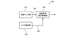
図1は本実施の形態に係る音声入力装置の構成について説明するための図である。 FIG. 1 is a diagram for explaining a configuration of a voice input device according to the present embodiment.
本実施の形態に係る音声入力装置700は、差動マイク部710を含む。差動マイク部710は、2つの受音部に入力される音声信号に基づき差動信号730を生成して出力する。差動信号は複数のマイクロフォンからの入力信号に基づき生成されてもよいし、1つのマイクロフォンで振動膜の表面および裏面に入力される音圧差に基づき生成されてもよい。
本実施の形態に係る音声入力装置700は、ノイズ測定部740を含む。ノイズ測定部740は、差動マイクの周辺のノイズを測定して測定結果750を出力する。ノイズ測定部740は、例えばノイズ収集用のマイクロフォン(例えば全指向性を持つマイクロフォン)を設けて音を収集し、ノイズのスペクトルをデジタル的に検出してノイズの大きさを測定してもよい。
本実施の形態に係る音声入力装置700は、差動信号抑圧制御部760を含む。差動信号抑圧制御部760は、ノイズ測定部740の測定結果に基づき、差動マイク部710から出力される差動信号730の所定周波数以上の周波数成分を抑圧する。例えばノイズ測定部740の測定結果750を所定の閾値と比較して比較結果に基づき、差動マイク部710から出力される差動信号730の所定周波数以上の周波数成分の抑圧の有無を制御してもよい。
差動信号730の所定周波数以上の周波数成分の抑圧はローパスフィルタを用いて行ってもよい。ローパスフィルタは、1次の遮断特性を有するフィルタを用いてもよい。図13で説明するように差分信号の高周波数域は1次特性(20dB/dec)で上がっていくため、この逆特性を持つ1次のローパスフィルタで高域を減衰させると、差分信号の周波数特性をフラットに保つことができ、聴感上の違和感が発生するのを防止することができる。
Suppression of frequency components of the
またローパスフィルタのカットオフ周波数は、1kHz以上、5kHz以下の間のいずれかの値に設定してもよい。 The cut-off frequency of the low-pass filter may be set to any value between 1 kHz and 5 kHz.
ローパスフィルタ部のカットオフ周波数は、低く設定しすぎると音がこもったようになり、高く設定しすぎると高域ノイズが耳障りであるので、マイクロフォン間の距離に応じて適切な値に設定することが好ましい。最適なカットオフ周波数はマイクロフォン間の距離によって変わるが、例えばマイクロフォン間の距離が約5mm程度の場合にはローパスフィルタ部のカットオフ周波数を1.5kHz以上、3kHz以下に設定することが好ましい。 If the cutoff frequency of the low-pass filter section is set too low, the sound will be muffled, and if it is set too high, the high-frequency noise will be annoying, so set it to an appropriate value according to the distance between the microphones. Is preferred. The optimum cutoff frequency varies depending on the distance between the microphones. For example, when the distance between the microphones is about 5 mm, it is preferable to set the cutoff frequency of the low-pass filter unit to 1.5 kHz or more and 3 kHz or less.
図12は、図11において、差動マイクの後段にローパスフィルタを設けた場合の周波数特性について説明するための図である。横軸は周波数であり縦軸は出力値(デシベル)である。1002’は音源が差動マイクから25mm程度の距離にある場合(接話型音声入力装置において想定される話者の位置に音源がある場合)の周波数と差動マイクの出力値(デシベル)の関係を示す関数のグラフである。1004’は音源が差動マイクから1000mm程度の距離にある場合(接話型音声入力装置において十分に遠方の雑音合)の周波数と差動マイクの出力値(デシベル)の関係を示す関数のグラフである。 FIG. 12 is a diagram for explaining frequency characteristics when a low-pass filter is provided in the subsequent stage of the differential microphone in FIG. The horizontal axis is frequency and the vertical axis is output value (decibel). 1002 ′ represents the frequency and the output value (decibel) of the differential microphone when the sound source is at a distance of about 25 mm from the differential microphone (when the sound source is at the position of the speaker assumed in the close-talking speech input device). It is a graph of the function which shows a relationship. 1004 'is a graph of a function indicating the relationship between the frequency and the output value (decibel) of the differential microphone when the sound source is at a distance of about 1000 mm from the differential microphone (noise far enough in the close-talking voice input device). It is.
1002’1004’に示すように、差動マイクの後段にローパスフィルタを設けることで、近傍の話者及び背景雑音の高域が強調されるのを抑圧することができる。 As indicated by reference numeral 1002'1004 ', by providing a low-pass filter in the subsequent stage of the differential microphone, it is possible to suppress the emphasis of the nearby speaker and high frequency of background noise.
図13は、差動マイクの周波数特性について説明するための図である。横軸は周波数であり縦軸はゲインである。1010は、差動マイクの話者想定位置での周波数とゲインの関係を示すグラフであり、例えば第1のマイクロフォン710−1および第2のマイクロフォン710−2の中心から25mm程度離れた位置での周波数特性を表している。1012は、差動マイクの後段にローパスフィルタを設け、ローパスフィルタ通過後の差動信号の周波数とゲインの関係を示すグラフである。 FIG. 13 is a diagram for explaining the frequency characteristics of the differential microphone. The horizontal axis is frequency and the vertical axis is gain. Reference numeral 1010 is a graph showing the relationship between the frequency and gain at the assumed speaker position of the differential microphone. For example, at a position about 25 mm away from the center of the first microphone 710-1 and the second microphone 710-2. It represents frequency characteristics. Reference numeral 1012 is a graph showing the relationship between the frequency and gain of the differential signal after the low-pass filter is provided after the differential microphone.
第1のマイクロフォン712−1および第2のマイクロフォン712−2がフラットな周波数特性であっても、1010に示すように差分信号の高周波数域は約1kHz付近から1次特性(20dB/dec)で上がっていくので、この逆特性を持つ1次のローパスフィルタで高域を減衰させると、差分信号の周波数特性をフラットにすることができ、聴感上の違和感が発生するのを防止することができる。 Even if the first microphone 712-1 and the second microphone 712-2 have flat frequency characteristics, as shown by 1010, the high frequency range of the differential signal has a primary characteristic (20 dB / dec) from about 1 kHz. When the high frequency band is attenuated by the first-order low-pass filter having the reverse characteristic, the frequency characteristic of the differential signal can be flattened, and the sense of incongruity can be prevented from occurring. .
一方、人間の耳は年齢と共に高域での感度が低下する傾向にあるので、状況によっては高域を強調した方がクリアに聞こえる場合がある。 On the other hand, human ears tend to be less sensitive at high frequencies with age, so depending on the situation, it may sound clearer when the high frequencies are emphasized.
本実施の形態では、ノイズ測定部740の測定結果に基づき、差動マイク部710から出力される差動信号の所定周波数以上の周波数成分を抑圧の有無や抑圧する周波数帯域を変更することができる。従って例えば周囲の雑音が所定のレベルより小さい場合や高周波雑音が少ない場合には、ローパスフィルタをオフにして(ローパスフィルタを通過させないで)出力し、周囲の雑音が所定のレベルよりも大きい場合(高周波、低周波を問わず周囲雑音レベルが高い場合)にはローパスフィルタをオンにして(ローパスフィルタを通過させて)出力することで、差動マイクの特性を生かすとともに聞き取りやすい音声信号を提供する音声入力装置(静かな環境では高域を強調して音声を明瞭にし、高騒音環境では背景雑音高域が強調されるのを抑圧してSNR(Signal to Noise Ratio)を向上させる音声入力装置)を提供することができる。
In the present embodiment, based on the measurement result of the
図2,図3は本実施の形態に係る音声入力装置の差動信号抑圧制御部の構成の一例について説明するための図である。 2 and 3 are diagrams for explaining an example of the configuration of the differential signal suppression control unit of the voice input device according to the present embodiment.
差動信号抑圧制御部760は、差動マイク部710から出力される差動信号730の所定周波数以上の周波数成分を抑圧するフィルタを含み、ノイズ測定部740の測定結果750を所定の閾値と比較してノイズの有無又は強弱を判定し、ノイズ有り又はノイズ強と判定した場合には前記フィルタを用いて差動信号の所定周波数以上の周波数成分を抑圧してもよい。
The differential signal
例えば図2に示すように、差動信号抑圧制御部760を、差動信号730の高域の周波数成分をカットするローパスフィルタ770と、ノイズ測定部740の測定結果750に基づき差動信号730の出力経路を切り替えるための切り替え制御信号766を生成して出力する切り替え制御信号生成部762と、切り替え制御信号766に基づき差動信号730の出力経路をローパスフィルタ770通過またはローパスフィルタ770非通過のいずれかに切り替える切り替え部762を含んで構成してもよい。切り替え部762は、例えばスイッチ回路等や選択回路等で構成しても良い。
For example, as illustrated in FIG. 2, the differential signal
差動信号抑圧制御部760は、ノイズ測定部740の測定結果を1又は複数の基準値と比較して比較結果に基づき、差動マイク部710から出力される差動信号730の高域抑圧する周波数帯域を変更するようにしてもよい。
The differential signal
例えば図3に示すように、差動信号抑圧制御部760を、差動信号730の所定周波数以上の周波数成分を抑圧するフィルタであって遮断周波数域の異なる複数のフィルタ(ここでは第1のローパスフィルタ766、第2のローパスフィルタ768)と、ノイズ測定部740の測定結果750に基づき差動信号730の出力経路を切り替えるための切り替え制御信号766を生成して出力する切り替え制御信号生成部762と、切り替え制御信号766に基づき差動信号730の出力経路を第1のローパスフィルタ772通過または第2のローパスフィルタ774通過に切り替える切り替え部762を含んで構成してもよい。切り替え部762は、例えばスイッチ回路等や選択回路等で構成しても良い。
For example, as shown in FIG. 3, the differential signal
なお、カットオフ周波数を変更可能なローパスフィルタを用いる場合には切り替え制御信号766に基づき、前記ローパスフィルタのカットオフ周波数を変更する制御を行ってもよい。抵抗およびコンデンサでローパスフィルタを構成する場合は、抵抗値を変更することで容易にカットオフ周波数の変更が可能である。
When a low-pass filter that can change the cutoff frequency is used, control for changing the cutoff frequency of the low-pass filter may be performed based on the switching
例えば、カットオフ周波数が1.5kHzの第1のローパスフィルタ766と、カットオフ周波数が10kHzの第2のローパスフィルタ768とを用意し、これらをノイズレベルに応じて選択的に切り替えてもよい。高騒音下においてはカットオフ周波数の低い第1のローパスフィルタ766を使用して、遠方雑音を抑圧し、かつ背景ノイズの高域が強調されて耳障りになるのを抑えることができる。一方、低騒音下においてはカットオフ周波数の高い第2のローパスフィルタ766を使用して、高域強調型の特性となるようにする。ここで、低騒音下においては背景ノイズの高域パワー自体が低いため、高域強調型の特性としても耳障りになることはなく、話者音声の高域が強調されることで年齢と共に低下する耳の高域感度を補って明瞭に音声を聴き取ることが可能である。
For example, a first low-
従って、ノイズが所定の閾値以上である場合には第1のローパスフィルタ766を使用し、ノイズが所定の閾値未満である場合には第2のローパスフィルタ766を使用するように構成してもよい。
Accordingly, the first low-
図4は本実施の形態に係る音声入力装置の差動マイク部の構成の一例について説明するための図である。 FIG. 4 is a diagram for explaining an example of the configuration of the differential microphone unit of the voice input device according to the present embodiment.
差動マイク部710は、第1の振動膜を有する第1のマイクロフォン712−1と、第2の振動膜を有する第2のマイクロフォン712−2と、差動信号生成部714を含んで構成しても良い。 差動信号生成部714は、第1のマイクロフォン712−1で取得された第1の電圧信号S1と、前記第2のマイクロフォン712−2で取得された第2の電圧信号S2とに基づき第1の電圧信号S1と第2の電圧信号S2の差分信号を生成する。
The
このようにすると、第1及び第2のマイクロフォンで取得された第1及び第2の電圧信号の差を示す差分信号を、雑音成分が除去された、入力音声を示す信号とみなすことができる。そのため、本発明によると、差分信号を生成するだけの単純な構成で雑音除去機能を実現することが可能な音声入力装置を提供することができる。 In this way, the difference signal indicating the difference between the first and second voltage signals acquired by the first and second microphones can be regarded as a signal indicating the input sound from which the noise component has been removed. Therefore, according to the present invention, it is possible to provide a voice input device capable of realizing a noise removal function with a simple configuration that only generates a differential signal.
なお、この音声入力装置では、差分信号生成部は、第1及び第2の電圧信号に対する解析処理(フーリエ解析処理など)を行うことなく、差動信号を生成する。そのため、差分信号生成部の信号処理負担を軽減して、非常に簡易な回路で、低コストに実現することが可能である。 In this voice input device, the differential signal generation unit generates a differential signal without performing analysis processing (Fourier analysis processing or the like) on the first and second voltage signals. Therefore, it is possible to reduce the signal processing burden of the differential signal generation unit and realize it at a low cost with a very simple circuit.
なお差動信号生成部714は、第1のマイクロフォン712−1で取得された第1の電圧信号S1を入力して所定の増幅率(ゲイン)で増幅して、所定のゲインで増幅された第1の電圧信号S1’と、前記第2のマイクロフォン712−2で取得された第2の電圧信号S2の差分に基づき差動信号730を生成して出力してもよい。
The differential
また差動信号生成部714は、第1のマイクロフォン712−1で取得された第1の電圧信号S1および第2のマイクロフォン712−2で取得された第2の電圧信号S2の少なくとも一方に所定遅延を与えて、少なくとも一方に遅延を与えられた第1の電圧信号と第2の電圧信号の差分に基づき差動信号を生成して出力してもよい。
Further, the differential
ここで、マイクロフォンとは、音響信号を電気信号へ変換する電気音響変換器である。第1及び第2のマイクロフォン712−1、712−2は、それぞれ、第1及び第2の振動膜(振動板)の振動を、電圧信号として出力する変換器であってもよい。 Here, the microphone is an electroacoustic transducer that converts an acoustic signal into an electrical signal. The first and second microphones 712-1 and 712-2 may be converters that output the vibrations of the first and second diaphragms (diaphragm) as voltage signals, respectively.
第1及び第2のマイクロフォン712−1、712−2の機構については特に限定されるものではない。振動膜を有するコンデンサ型マイクロフォンでもよい。振動膜は、音波を受けて振動する膜(薄膜)で、導電性を有し、電極の一端を形成している。コンデンサ型マイクロフォンの電極は、振動膜と対向して配置され、振動膜と電極とで容量を形成すし、音波が入射すると、振動膜が振動して、振動膜と電極との間隔が変化し、振動膜電極との間の静電容量が変化する。この静電容量の変化を、例えば電圧の変化として出力することによって、コンデンサ型マイクロフォンに入射する音波を、電気信号に変換することができる。なお、本発明に適用可能なマイクロフォンは、コンデンサ型マイクロフォンに限られるものではなく、既に公知となっているいずれかのマイクロフォンを適用することができる。例えば、第1及び第2のマイクロフォン712−1、712−2として、動電型(ダイナミック型)、電磁型(マグネティック型)、圧電型(クリスタル型)等のマイクロフォンを適用してもよい。 The mechanism of the first and second microphones 712-1 and 712-2 is not particularly limited. A condenser microphone having a vibration film may be used. The vibrating membrane is a membrane (thin film) that vibrates in response to sound waves, has conductivity, and forms one end of the electrode. The electrode of the condenser microphone is disposed opposite to the vibrating membrane, and a capacitance is formed by the vibrating membrane and the electrode. When a sound wave is incident, the vibrating membrane vibrates, and the interval between the vibrating membrane and the electrode changes, The capacitance between the vibrating membrane electrode changes. By outputting the change in capacitance as a change in voltage, for example, sound waves incident on the condenser microphone can be converted into an electrical signal. Note that the microphone applicable to the present invention is not limited to a condenser microphone, and any microphone that is already known can be applied. For example, as the first and second microphones 712-1 and 712-2, electrodynamic (dynamic), electromagnetic (magnetic), and piezoelectric (crystal) microphones may be applied.
第1及び第2のマイクロフォン712−1、712−2は、第1及び第2の振動膜がシリコンによって構成されたシリコンマイク(Siマイク)であってもよい。シリコンマイクを利用することで、第1及び第2のマイクロフォン712−1、712−2の小型化、及び、高性能化を実現することができる。このとき、第1及び第2のマイクロフォン712−1、712−2は、1つの集積回路装置として構成されていてもよい。すなわち、第1及び第2のマイクロフォン712−1、712−2は、1つの半導体基板に構成されていてもよい。第1及び第2のマイクロフォン712−1、712−2は、いわゆるメムス(MEMS:Micro Electro Mechanical Systems)として構成されていてもよい。 第1及び第2の振動膜12,22は、例えば、中心間距離が5.2mm以下になるように配置されていてもよい。 The first and second microphones 712-1 and 712-2 may be silicon microphones (Si microphones) in which the first and second vibrating membranes are made of silicon. By using a silicon microphone, the first and second microphones 712-1 and 712-2 can be reduced in size and performance. At this time, the first and second microphones 712-1 and 712-2 may be configured as one integrated circuit device. That is, the first and second microphones 712-1 and 712-2 may be configured on one semiconductor substrate. The first and second microphones 712-1 and 712-2 may be configured as so-called MEMS (Micro Electro Mechanical Systems). For example, the first and second vibrating membranes 12 and 22 may be arranged such that the center-to-center distance is 5.2 mm or less.
なお、本実施の形態に係る音声入力装置では、第1及び第2の振動膜の向きは、特に限定されるものではない。 In the voice input device according to the present embodiment, the directions of the first and second vibrating membranes are not particularly limited.
図5は本実施の形態に係る音声入力装置のノイズ測定部の構成の一例について説明するための図である。 FIG. 5 is a diagram for explaining an example of the configuration of the noise measurement unit of the voice input device according to the present embodiment.
ノイズ測定部740は、第1のマイクロフォン712−1で取得された第1の電圧信号と、前記第2のマイクロフォン712−1で取得された第2の電圧信号の少なくとも一方に基づき前記差動マイクの周辺のノイズを測定してノイズ測定結果信号750を出力する。
The
差動信号抑圧制御部760は、ノイズ測定結果信号750に基づき、差動マイク部710から出力される差動信号の所定周波数以上の周波数成分を抑圧する制御を行う。
Based on the noise
このようにすれば、第1のマイクロフォン712−1で取得された第1の電圧信号と、前記第2のマイクロフォン712−2で取得された第2の電圧信号の少なくとも一方に基づき前記差動マイクの周辺のノイズを測定するため、ノイズ測定用のマイクロフォンを別途設ける必要がない。 In this way, the differential microphone is based on at least one of the first voltage signal acquired by the first microphone 712-1 and the second voltage signal acquired by the second microphone 712-2. Therefore, it is not necessary to separately provide a noise measurement microphone.
図6は本実施の形態に係る音声入力装置のノイズ測定部の構成の一例について説明するための図である。 FIG. 6 is a diagram for explaining an example of the configuration of the noise measurement unit of the voice input device according to the present embodiment.
ノイズ測定部740は、第2のマイクロフォン712−2で取得された第2の電圧信号にノイズ検出用の遅延を与えて出力するノイズ検出用遅延部742と、ノイズ検出用遅延部742によってノイズ検出用の所定の遅延を与えられた第2の電圧信号744と、第1のマイクロフォン712−1で取得された第1の電圧信号S1との差分をとって差分に基づきノイズ測定結果信号750を生成するノイズ測定結果信号生成部746と、を含んで構成してもよい。
The
このようにすると差動マイクの指向特性を制御して話者音声を除いた周囲の雑音の状態を検出し、検出した雑音のレベルに応じて前記差動マイク部から出力される差動信号の高域周波数の抑圧の有無、又は抑圧する周波数帯域を変更する制御を行うことができる。 In this way, the directivity characteristics of the differential microphone are controlled to detect the surrounding noise state excluding the speaker voice, and the differential signal output from the differential microphone unit according to the detected noise level. It is possible to control whether or not to suppress the high frequency, or change the frequency band to be suppressed.
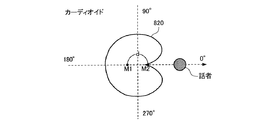
図7、図8は差動マイクの指向性について説明するための図である。 7 and 8 are diagrams for explaining the directivity of the differential microphone.
図7は2つのマイクロフォンM1、M2の位相がずれていない状態での指向特性を表している。円状の領域810−1と、810−2は、両マイクロフォンM1、M2の出力の差分により得られる指向特性を示しており、両マイクロフォンM1、M2を結ぶ直線方向を0度、180度とし、両マイクロフォンM1、M2を結ぶ直線方向と直角な方向を90度、270度とすると、0度、180度方向に最大感度を有し、90度、270度方向に感度を持たない両指向性であることを表している。
FIG. 7 shows the directivity characteristics when the two microphones M1 and M2 are not out of phase. Circular regions 810-1 and 810-2 indicate the directivity obtained by the difference between the outputs of both
両マイクロフォンM1、M2でとらえた信号の一方に遅延を与えた場合、指向特性が変化する。例えば、マイクロフォンM2の出力に対し、マイクロフォン間隔dを音速cで除算した時間に相当する遅延を与えた場合、両マイクロフォンM1、M2の指向性を示す領域は図8の820に示すようなカーディオイド型になる。このような場合、0度の話者方向に対して感度のない(ヌル)指向特性を実現でき、話者の音声を選択的にカットして周囲の音(周囲の雑音)のみをとらえることができる。 When a delay is given to one of the signals captured by both microphones M1 and M2, the directivity changes. For example, when a delay corresponding to the time obtained by dividing the microphone interval d by the speed of sound c is given to the output of the microphone M2, the area indicating the directivity of both microphones M1 and M2 is a cardioid type as shown by 820 in FIG. become. In such a case, it is possible to realize insensitive (null) directional characteristics with respect to the 0-degree speaker direction, and to selectively cut the speaker's voice and capture only the surrounding sound (ambient noise). it can.
例えば、マイクロフォン間隔dを5mmとした場合、音速を340m/sとすると、遅延量としては14.7μsを設定すればよい。 For example, when the microphone interval d is 5 mm and the sound speed is 340 m / s, the delay amount may be set to 14.7 μs.
従ってノイズ検出用遅延部742で設定するノイズ検出用の遅延を、第1および第2の振動板の中心間距離を音速で除算した時間に設定するようにしてもよい。例えば用遅延部742で第2のマイクロフォン712−2で取得された第2の電圧信号にマイクロフォン間隔dを音速cで除算した時間に相当する遅延をあたえて、当該遅延を与えられた第2の電圧信号744と、第1のマイクロフォン712−1で取得された第1の電圧信号S1との差分をとって差分に基づきノイズ測定結果信号750を生成してもよい。このように遅延量を設定して、音声入力装置の指向特性をカーディオイド型にし、話者の位置を指向性のヌル位置近傍に設定することで、話者音声をカットして周囲雑音のみを拾いやすい指向性となるため、ノイズ検出用に利用することができる。
Therefore, the noise detection delay set by the noise
なお、前記ノイズ検出用の遅延は、第1および第2の振動板の中心間距離(図7のd参照)を音速で除算した時間でなくてもよい。話者の方向が0度方向でない場合であっても、指向特性の感度のない方向(ヌル)を話者方向に設定できれば、話者音声をカットして周囲の雑音を拾うような指向性をもつノイズ検出に適した特性を実現することができる。例えば、ハイパーカーディオイド、スーパーカーディオイド型の指向特性を持つように遅延を設定して、話者音声をカットするものであって構わない。 The delay for noise detection may not be the time obtained by dividing the distance between the centers of the first and second diaphragms (see d in FIG. 7) by the speed of sound. Even if the direction of the speaker is not 0 degrees, if the direction with no sensitivity of the directivity (null) can be set as the direction of the speaker, the directivity that cuts the speaker's voice and picks up the surrounding noise can be obtained. Characteristics suitable for noise detection can be realized. For example, the speaker voice may be cut by setting a delay so as to have a hyper cardioid or super cardioid type directivity characteristic.
図9は差動信号抑圧制御部のローパスフィルタのオン/オフの切り替えの動作例を示すフローチャートである。 FIG. 9 is a flowchart showing an operation example of on / off switching of the low-pass filter of the differential signal suppression control unit.
ノイズ測定部から出力されるノイズ測定結果信号が所定のしきい値(LTH)より小さい場合には(ステップS110)、ローパスフィルタをオフにし(ステップS112)、ノイズ測定結果信号が所定のしきい値(LTH)よりの小さくない場合には(ステップS110)、ローパスフィルタをオンにする(ステップS114)。ローパスフィルタをオンにするとはローパスフィルタを通過させた信号を出力することを意味し、ローパスフィルタをオフにするとは、ローパスフィルタを通過させない信号を出力することを意味する。 When the noise measurement result signal output from the noise measurement unit is smaller than the predetermined threshold value (LTH) (step S110), the low-pass filter is turned off (step S112), and the noise measurement result signal is the predetermined threshold value. If it is not smaller than (LTH) (step S110), the low pass filter is turned on (step S114). Turning on the low-pass filter means outputting a signal that has passed through the low-pass filter, and turning off the low-pass filter means outputting a signal that does not pass through the low-pass filter.
図16は、差動信号抑圧制御部のローパスフィルタのカットオフ周波数の切り替えの動作例を示すフローチャートである。 FIG. 16 is a flowchart illustrating an operation example of switching the cutoff frequency of the low-pass filter of the differential signal suppression control unit.
ノイズ測定部から出力されるノイズ測定結果信号が所定のしきい値(LTH)より小さい場合には(ステップS130)、ローパスフィルタのカットオフ周波数fcを高く(例えば、fh=10kHz)に設定し(ステップS132)、ノイズ測定結果信号が所定のしきい値(LTH)よりの小さくない場合には(ステップS130)、ローパスフィルタのカットオフ周波数fcを低く(例えば、fl=1.5kHz)に設定する(ステップS114)。 When the noise measurement result signal output from the noise measurement unit is smaller than the predetermined threshold value (LTH) (step S130), the low-pass filter cutoff frequency fc is set high (for example, fh = 10 kHz) ( In step S132), when the noise measurement result signal is not smaller than the predetermined threshold value (LTH) (step S130), the low-pass filter cut-off frequency fc is set low (for example, fl = 1.5 kHz). (Step S114).
図17は、フィルタのカットオフ周波数fcを変化させたときのマイクロフォン特性と、フィルタとを合わせた総合特性を示している。実線は差動マイクのみの周波数特性を示している。ローパスフィルタのカットオフ周波数fcをfl(=1.5kHz)にした場合、差動マイクの高域が抑圧されて、点線のようにほぼフラットな特性になる。そして、ローパスフィルタのカットオフ周波数fcをfh(=10kHz)にした場合、差動マイクの高域を抑圧する帯域が高域側にシフトするため、一点鎖線のように1.5kHzから10kHzにかけてゲインが増加し、10kHz以降でフラットとなるような特性を示す。 FIG. 17 shows the overall characteristics combining the microphone characteristics when the cutoff frequency fc of the filter is changed and the filter. The solid line shows the frequency characteristics of only the differential microphone. When the cut-off frequency fc of the low-pass filter is set to fl (= 1.5 kHz), the high frequency range of the differential microphone is suppressed, and the characteristics are almost flat as indicated by a dotted line. When the cut-off frequency fc of the low-pass filter is set to fh (= 10 kHz), the band for suppressing the high band of the differential microphone shifts to the high band side, so that the gain is increased from 1.5 kHz to 10 kHz as indicated by a dashed line. Increases and becomes flat after 10 kHz.
音情報を出力するスピーカを有する音声入力装置においては、図14に示すようにノイズ測定結果信号750に基づきスピーカ780の音量を制御する音量制御部770を含むようにしてもよい。
The voice input device having a speaker that outputs sound information may include a
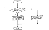
図10はノイズ検出によるスピーカの音量制御の動作例を示すフローチャートである。 FIG. 10 is a flowchart showing an operation example of speaker volume control by noise detection.
ノイズ測定部から出力されるノイズ測定結果信号が所定のしきい値(LTH)よりの小さい場合には(ステップS120)スピーカの音量を第1の値に設定し(ステップS122)、ノイズ測定部から出力されるノイズ測定結果信号が所定のしきい値(LTH)よりの小さくない場合には(ステップS120)スピーカの音量を第1のより大きな音量の第2の値に設定する(ステップS124)。 When the noise measurement result signal output from the noise measurement unit is smaller than a predetermined threshold (LTH) (step S120), the volume of the speaker is set to the first value (step S122), and the noise measurement unit If the output noise measurement result signal is not smaller than the predetermined threshold value (LTH) (step S120), the volume of the speaker is set to the second value of the first larger volume (step S124).
またノイズ測定部から出力されるノイズ測定結果信号が所定のしきい値(LTH)よりの小さい場合にはスピーカの音量を下げ、ノイズ測定部から出力されるノイズ測定結果信号が所定のしきい値(LTH)よりの小さくない場合にはスピーカの音量を上げるようにしてもよい。 When the noise measurement result signal output from the noise measurement unit is smaller than a predetermined threshold value (LTH), the volume of the speaker is lowered, and the noise measurement result signal output from the noise measurement unit is the predetermined threshold value. If it is not smaller than (LTH), the volume of the speaker may be increased.
図15は、本実施の形態に係る音声入力装置の他の構成について説明するための図である。 FIG. 15 is a diagram for explaining another configuration of the voice input device according to the present embodiment.
本実施の形態に係る音声入力装置700’は、差動マイク部710を含む。差動マイク部710は、差動マイク(2つのマイクロフォン)からの入力信号に基づき差動信号730を生成して出力する。
The
なお、ノイズ測定結果に基づく、ローパスフィルタのオン/オフ制御、あるいはカットオフ周波数fcの変更、あるいはスピーカの音量制御について、単一の閾値LTHに対する大小のみで制御するのではなく、複数の閾値を設けてヒステリシスを持って制御するものであっても構わない。例えば、LTH1以下で第1のモード(ローパスフィルタオフ)に移行、LTH2以上で第2のモード(ローパスフィルタオン)に移行するような構成であっても構わない。 In addition, on / off control of the low-pass filter, change of the cut-off frequency fc, or volume control of the speaker based on the noise measurement result, a plurality of threshold values are not controlled by only the magnitude of the single threshold value LTH. It may be provided and controlled with hysteresis. For example, the configuration may be such that the first mode (low-pass filter off) is shifted to LTH1 or less, and the second mode (low-pass filter on) is shifted to LTH2 or more.
本実施の形態に係る音声入力装置700’は、ノイズ抑制モード情報受け付け部790を含む。ノイズ抑制モード情報受け付け部790は、差動マイクのノイズ抑制に関するモードの設定/変更に係るノイズ抑制モード情報を受け付ける。ノイズ抑制モード情報は、音声入力装置に設けられたスイッチやボタン等の操作部からの操作入力により受け付けても良い。
The
本実施の形態に係る音声入力装置700は、差動信号抑圧制御部760’を含む。差動信号抑圧制御部760’は、ノイズ抑制モード情報792に基づき、差動マイク部710から出力される差動信号の所定周波数以上の周波数成分を抑圧の有無を制御してもよい。例えばノイズ抑制モード情報792が第1のモード(例えばノイズ抑圧有りモード、高騒音環境モード)の場合には、差動マイク部710から出力される差動信号730の所定周波数以上の周波数成分の抑圧を行い、第2のモード(例えばノイズ抑圧無しモード、静寂環境モード)の場合には、差動マイク部710から出力される差動信号730の所定周波数以上の周波数成分の抑圧を行なわないようにしてもよい。
The
また差動信号抑圧制御部760’は、ノイズ抑制モード情報792に基づき、差動マイク部710から出力される差動信号の抑圧する周波数帯域を変更する制御(カットオフ周波数の異なるローパスフィルタを切り替える制御)を行っても良い。例えば第1のローパスフィルタとしてカットオフ周波数が1.5kHz以上、第2のローパスフィルタとしてカットオフ周波数が10kHz以上を用意して、ノイズ抑制モード情報792が第1のモード(例えばノイズ抑圧有りモード、高騒音環境モード)の場合には、差動マイク部710から出力される差動信号730を第1のローパスフィルタを通過させて1.5kHz以上の周波数成分の抑圧を行い、第2のモード(例えばノイズ抑圧無しモード、静寂環境モード)の場合には、第2のローパスフィルタを通過させて10kHz以上の周波数成分の抑圧を行うようにしてもよい。
Further, the differential signal
高騒音下においてはカットオフ周波数の低い第1のローパスフィルタを使用することで、遠方雑音を抑圧し、かつ背景ノイズの高域が強調されて耳障りになるのを抑えることができる。一方、低騒音下においてはカットオフ周波数の高い第2のローパスフィルタを使用することで、高域強調型の特性となるようにする。ここで、低騒音下においては背景ノイズの高域パワー自体が低いため、高域強調型の特性としても耳障りになることはなく、話者音声の高域が強調されることで年齢と共に低下する耳の高域感度を補って明瞭に音声を聴き取ることが可能である。 By using the first low-pass filter having a low cut-off frequency under high noise, it is possible to suppress distant noise and to suppress harshness by enhancing the high frequency of the background noise. On the other hand, under low noise, the second low-pass filter having a high cut-off frequency is used so as to achieve a high-frequency emphasis type characteristic. Here, since the high frequency power of the background noise itself is low under low noise, the high frequency emphasis type characteristic is not harsh, and the high frequency of the speaker's voice is emphasized and decreases with age. It is possible to listen to the sound clearly by compensating the high frequency sensitivity of the ear.
なお、本発明は、上述の実施の形態に限定されるものではなく、種々の変形が可能である。本発明は、実施の形態で説明した構成と実質的に同一の構成(例えば、機能、方法及び結果が同一の構成、あるいは目的及び効果が同一の構成)を含む。また、本発明は、実施の形態で説明した構成の本質的でない部分を置き換えた構成を含む。また、本発明は、実施の形態で説明した構成と同一の作用効果を奏する構成又は同一の目的を達成することができる構成を含む。また、本発明は、実施の形態で説明した構成に公知技術を付加した構成を含む。 In addition, this invention is not limited to the above-mentioned embodiment, A various deformation | transformation is possible. The present invention includes configurations that are substantially the same as the configurations described in the embodiments (for example, configurations that have the same functions, methods, and results, or configurations that have the same objects and effects). In addition, the invention includes a configuration in which a non-essential part of the configuration described in the embodiment is replaced. In addition, the present invention includes a configuration that exhibits the same operational effects as the configuration described in the embodiment or a configuration that can achieve the same object. Further, the invention includes a configuration in which a known technique is added to the configuration described in the embodiment.
700 音声入力装置、710 差動マイク部、712−1 第1のマイクロフォン、712−2 第2のマイクロフォン、714 差動信号生成部、730 差動信号、740 ノイズ測定部、742 ノイズ検出用遅延部、746 ノイズ測定結果信号生成部、750 ノイズ測定結果尊号、760 差動信号抑圧制御部、770 音量制御部、780 スピーカ、790 ノイズ抑制モード情報受け付け部 700 Audio Input Device, 710 Differential Microphone Unit, 712-1 First Microphone, 712-2 Second Microphone, 714 Differential Signal Generation Unit, 730 Differential Signal, 740 Noise Measurement Unit, 742 Noise Detection Delay Unit , 746 Noise measurement result signal generation unit, 750 Noise measurement result honor, 760 Differential signal suppression control unit, 770 Volume control unit, 780 Speaker, 790 Noise suppression mode information reception unit
Claims (8)
第2の振動膜を有する第2のマイクロフォンと、
前記第1のマイクロフォンで取得された第1の電圧信号と、前記第2のマイクロフォンで取得された第2の電圧信号と差分に基づき第1の電圧信号と第2の電圧信号の差動信号を生成する差動信号生成部と、
前記第1のマイクロフォンおよび前記第2のマイクロフォンの周辺ノイズを測定するノイズ測定部と、
前記差動信号の所定周波数以上の周波数成分の抑圧の有無の制御及び抑圧する周波数帯域を変更する制御の少なくとも一方を行う差動信号抑圧制御部とを含み、
前記第1のマイクロフォンと前記第2のマイクロフォンを結ぶ方向の想定話者の音声を収音する音声入力装置であって、
前記ノイズ測定部は、
前記第2の電圧信号に遅延を与えて出力する遅延部を含み、
前記遅延部によって所定の遅延を与えられた第2の電圧信号と、前記第1の電圧信号とを差分することにより前記想定話者方向に対して感度のない指向特性を形成して前記周辺ノイズを測定するものであり、
前記差動信号抑圧制御部は、
前記周辺ノイズの測定結果に基づき、前記差動信号の所定周波数以上の周波数成分の抑圧の有無の制御及び抑圧する周波数帯域を変更する制御の少なくとも一方を行うことを特徴とする音声入力装置。 A first microphone having a first vibrating membrane;
A second microphone having a second vibrating membrane;
Based on the difference between the first voltage signal acquired by the first microphone and the second voltage signal acquired by the second microphone, a differential signal of the first voltage signal and the second voltage signal is obtained. A differential signal generator to generate,
A noise measurement unit for measuring ambient noise of the first microphone and the second microphone;
A differential signal suppression control unit that performs at least one of control of the presence or absence of suppression of a frequency component equal to or higher than a predetermined frequency of the differential signal and control of changing a frequency band to be suppressed,
A voice input device that picks up a voice of an assumed speaker in a direction connecting the first microphone and the second microphone,
The noise measuring unit is
A delay unit that delays and outputs the second voltage signal;
A difference between the second voltage signal given a predetermined delay by the delay unit and the first voltage signal forms a directivity characteristic that is insensitive to the assumed speaker direction, and the ambient noise. Is to measure
The differential signal suppression controller is
An audio input device that performs at least one of control of presence / absence of suppression of a frequency component equal to or higher than a predetermined frequency of the differential signal and control of changing a frequency band to be suppressed based on a measurement result of the ambient noise.
前記遅延部の遅延は、前記第1の振動膜および前記第2の振動膜の中心間距離を音速で除算した時間に設定されることを特徴とする音声入力装置。 In claim 1,
The delay of the delay unit, voice input device, characterized in that it is set to the first vibrating membrane and the second vibrating membrane time obtained by dividing the distance between the centers in the speed of sound.
前記差動信号抑圧制御部は、
前記差動マイク部から出力される差動信号の所定周波数以上の周波数成分を抑圧するローパスフィルタを含み、
前記ノイズ測定部の測定結果に基づき、出力される差動信号の前記ローパスフィルタ通過の有無を切り替える制御を行うことを特徴とする音声入力装置。 In any one of Claims 1 thru | or 2.
The differential signal suppression controller is
Including a low-pass filter that suppresses a frequency component equal to or higher than a predetermined frequency of the differential signal output from the differential microphone unit;
An audio input device that performs control to switch presence / absence of an output differential signal passing through the low-pass filter based on a measurement result of the noise measurement unit .
前記差動信号抑圧制御部は、
前記差動マイク部から出力される差動信号の所定周波数以上の周波数成分を抑圧するローパスフィルタであって、抑圧する周波数帯域の異なる複数のローパスフィルタを含み、
前記ノイズ測定部の測定結果に基づき、出力される差動信号が通過するローパスフィルタを変更する制御を行うことを特徴とする音声入力装置。 In any one of Claims 1 thru | or 3,
The differential signal suppression controller is
A low-pass filter that suppresses a frequency component of a differential signal that is output from the differential microphone unit at a predetermined frequency or higher, and includes a plurality of low-pass filters having different frequency bands to be suppressed,
An audio input device that performs control to change a low-pass filter through which an output differential signal passes based on a measurement result of the noise measurement unit .
前記差動信号抑圧制御部は、
前記差動マイク部から出力される差動信号の所定周波数以上の周波数成分を抑圧するローパスフィルタであって、カットオフ周波数を変更可能なローパスフィルタを含み、
前記ノイズ測定部の測定結果に基づき、前記ローパスフィルタのカットオフ周波数を変更する制御を行うことを特徴とする音声入力装置。 In any one of Claims 1 thru | or 3,
The differential signal suppression controller is
A low-pass filter that suppresses a frequency component equal to or higher than a predetermined frequency of the differential signal output from the differential microphone unit, including a low-pass filter capable of changing a cutoff frequency;
An audio input device that performs control to change a cutoff frequency of the low-pass filter based on a measurement result of the noise measurement unit .
前記差動信号抑圧制御部は、
1次の遮断特性を有するローパスフィルタを用いて前記差動マイク部から出力される差動信号の所定周波数以上の周波数成分を抑圧することを特徴とする音声入力装置。 In any one of Claims 1 thru | or 5,
The differential signal suppression controller is
An audio input device that suppresses a frequency component of a differential signal output from the differential microphone unit using a low-pass filter having a primary cutoff characteristic.
前記差動信号抑圧制御部は、
カットオフ周波数が1kHz以上、5kHz以下のいずれかの値に設定されたローパスフィルタを用いて前記差動マイク部から出力される差動信号の周波数成分を抑圧することを特徴とする音声入力装置。 In any one of Claims 1 thru | or 6.
The differential signal suppression controller is
An audio input device, wherein a frequency component of a differential signal output from the differential microphone unit is suppressed using a low-pass filter whose cutoff frequency is set to any value between 1 kHz and 5 kHz.
音情報を出力するスピーカと、
前記ノイズ測定部の測定結果に基づき前記スピーカの音量を制御する音量制御部と、
をさらに含むことを特徴とする音声入力装置。 In any one of Claims 1 thru | or 7 ,
A speaker that outputs sound information;
A volume control unit for controlling the volume of the speaker based on the measurement result of the noise measurement unit;
A voice input device further comprising:
Priority Applications (6)
| Application Number | Priority Date | Filing Date | Title |
|---|---|---|---|
| JP2007317719A JP5097523B2 (en) | 2007-12-07 | 2007-12-07 | Voice input device |
| KR1020080122825A KR101164299B1 (en) | 2007-12-07 | 2008-12-05 | Sound input device |
| DE602008005826T DE602008005826D1 (en) | 2007-12-07 | 2008-12-08 | Sound input device |
| US12/330,227 US8249273B2 (en) | 2007-12-07 | 2008-12-08 | Sound input device |
| CN200810184541.9A CN101453684B (en) | 2007-12-07 | 2008-12-08 | Sound input device |
| EP08021309A EP2068309B1 (en) | 2007-12-07 | 2008-12-08 | Sound input device |
Applications Claiming Priority (1)
| Application Number | Priority Date | Filing Date | Title |
|---|---|---|---|
| JP2007317719A JP5097523B2 (en) | 2007-12-07 | 2007-12-07 | Voice input device |
Publications (2)
| Publication Number | Publication Date |
|---|---|
| JP2009141817A JP2009141817A (en) | 2009-06-25 |
| JP5097523B2 true JP5097523B2 (en) | 2012-12-12 |
Family
ID=40445402
Family Applications (1)
| Application Number | Title | Priority Date | Filing Date |
|---|---|---|---|
| JP2007317719A Expired - Fee Related JP5097523B2 (en) | 2007-12-07 | 2007-12-07 | Voice input device |
Country Status (6)
| Country | Link |
|---|---|
| US (1) | US8249273B2 (en) |
| EP (1) | EP2068309B1 (en) |
| JP (1) | JP5097523B2 (en) |
| KR (1) | KR101164299B1 (en) |
| CN (1) | CN101453684B (en) |
| DE (1) | DE602008005826D1 (en) |
Families Citing this family (34)
| Publication number | Priority date | Publication date | Assignee | Title |
|---|---|---|---|---|
| CN101589625B (en) | 2006-10-25 | 2011-09-21 | 弗劳恩霍夫应用研究促进协会 | Fraunhofer ges forschung |
| JP4530051B2 (en) * | 2008-01-17 | 2010-08-25 | 船井電機株式会社 | Audio signal transmitter / receiver |
| US8218778B2 (en) * | 2009-01-21 | 2012-07-10 | Fortemedia, Inc. | Method for showing array microphone effect |
| US20100239106A1 (en) * | 2009-03-19 | 2010-09-23 | Texas Instruments Incorporated | Probabilistic Method of Loudspeaker Detection |
| JP5691618B2 (en) * | 2010-02-24 | 2015-04-01 | ヤマハ株式会社 | Earphone microphone |
| US8989411B2 (en) * | 2011-04-08 | 2015-03-24 | Board Of Regents, The University Of Texas System | Differential microphone with sealed backside cavities and diaphragms coupled to a rocking structure thereby providing resistance to deflection under atmospheric pressure and providing a directional response to sound pressure |
| EP3657788B1 (en) | 2011-11-11 | 2021-08-04 | GE Video Compression, LLC | Effective prediction using partition coding |
| KR101663394B1 (en) | 2011-11-11 | 2016-10-06 | 지이 비디오 컴프레션, 엘엘씨 | Adaptive partition coding |
| EP2777286B1 (en) | 2011-11-11 | 2017-01-04 | GE Video Compression, LLC | Effective wedgelet partition coding |
| EP4161078A1 (en) | 2011-11-11 | 2023-04-05 | GE Video Compression, LLC | Effective wedgelet partition coding using spatial prediction |
| KR102008374B1 (en) * | 2012-08-03 | 2019-10-23 | 삼성전자주식회사 | Input device for portable terminal |
| CN106774882B (en) * | 2012-09-17 | 2020-01-31 | 联想(北京)有限公司 | information processing method and electronic equipment |
| US9860652B2 (en) * | 2015-03-23 | 2018-01-02 | Etymonic Design Incorporated | Test apparatus for binaurally-coupled acoustic devices |
| US9565493B2 (en) | 2015-04-30 | 2017-02-07 | Shure Acquisition Holdings, Inc. | Array microphone system and method of assembling the same |
| US9554207B2 (en) | 2015-04-30 | 2017-01-24 | Shure Acquisition Holdings, Inc. | Offset cartridge microphones |
| US10373608B2 (en) * | 2015-10-22 | 2019-08-06 | Texas Instruments Incorporated | Time-based frequency tuning of analog-to-information feature extraction |
| CN106909360A (en) * | 2015-12-23 | 2017-06-30 | 塞舌尔商元鼎音讯股份有限公司 | A kind of electronic installation, sound play device and balanced device method of adjustment |
| US10367948B2 (en) | 2017-01-13 | 2019-07-30 | Shure Acquisition Holdings, Inc. | Post-mixing acoustic echo cancellation systems and methods |
| US10157627B1 (en) * | 2017-06-02 | 2018-12-18 | Bose Corporation | Dynamic spectral filtering |
| WO2019231632A1 (en) | 2018-06-01 | 2019-12-05 | Shure Acquisition Holdings, Inc. | Pattern-forming microphone array |
| US11297423B2 (en) | 2018-06-15 | 2022-04-05 | Shure Acquisition Holdings, Inc. | Endfire linear array microphone |
| JP7166836B2 (en) * | 2018-08-09 | 2022-11-08 | 日置電機株式会社 | measuring device |
| EP3854108A1 (en) | 2018-09-20 | 2021-07-28 | Shure Acquisition Holdings, Inc. | Adjustable lobe shape for array microphones |
| JP2022526761A (en) | 2019-03-21 | 2022-05-26 | シュアー アクイジッション ホールディングス インコーポレイテッド | Beam forming with blocking function Automatic focusing, intra-regional focusing, and automatic placement of microphone lobes |
| CN113841419A (en) | 2019-03-21 | 2021-12-24 | 舒尔获得控股公司 | Housing and associated design features for ceiling array microphone |
| US11558693B2 (en) | 2019-03-21 | 2023-01-17 | Shure Acquisition Holdings, Inc. | Auto focus, auto focus within regions, and auto placement of beamformed microphone lobes with inhibition and voice activity detection functionality |
| DE102019002963A1 (en) * | 2019-04-25 | 2020-10-29 | Drägerwerk AG & Co. KGaA | Apparatus and method for monitoring sound and gas exposure |
| CN114051738A (en) | 2019-05-23 | 2022-02-15 | 舒尔获得控股公司 | Steerable speaker array, system and method thereof |
| EP3977449A1 (en) | 2019-05-31 | 2022-04-06 | Shure Acquisition Holdings, Inc. | Low latency automixer integrated with voice and noise activity detection |
| JP2022545113A (en) | 2019-08-23 | 2022-10-25 | シュアー アクイジッション ホールディングス インコーポレイテッド | One-dimensional array microphone with improved directivity |
| US11552611B2 (en) | 2020-02-07 | 2023-01-10 | Shure Acquisition Holdings, Inc. | System and method for automatic adjustment of reference gain |
| USD944776S1 (en) | 2020-05-05 | 2022-03-01 | Shure Acquisition Holdings, Inc. | Audio device |
| WO2021243368A2 (en) | 2020-05-29 | 2021-12-02 | Shure Acquisition Holdings, Inc. | Transducer steering and configuration systems and methods using a local positioning system |
| WO2022165007A1 (en) | 2021-01-28 | 2022-08-04 | Shure Acquisition Holdings, Inc. | Hybrid audio beamforming system |
Family Cites Families (16)
| Publication number | Priority date | Publication date | Assignee | Title |
|---|---|---|---|---|
| JPS577285U (en) * | 1980-06-13 | 1982-01-14 | ||
| US5267323A (en) * | 1989-12-29 | 1993-11-30 | Pioneer Electronic Corporation | Voice-operated remote control system |
| JPH04363995A (en) * | 1991-01-07 | 1992-12-16 | Canon Inc | Audio processing unit |
| US5550925A (en) * | 1991-01-07 | 1996-08-27 | Canon Kabushiki Kaisha | Sound processing device |
| JP3186892B2 (en) | 1993-03-16 | 2001-07-11 | ソニー株式会社 | Wind noise reduction device |
| JP3046203B2 (en) | 1994-05-18 | 2000-05-29 | 三菱電機株式会社 | Hands-free communication device |
| JPH09331377A (en) | 1996-06-12 | 1997-12-22 | Nec Corp | Noise cancellation circuit |
| JPH11243597A (en) * | 1998-02-25 | 1999-09-07 | Sony Corp | Microphone switching system |
| JP2001186241A (en) | 1999-12-27 | 2001-07-06 | Toshiba Corp | Telephone terminal device |
| JP2001189987A (en) * | 1999-12-28 | 2001-07-10 | Pioneer Electronic Corp | Narrow directivity microphone unit |
| US6704422B1 (en) * | 2000-10-26 | 2004-03-09 | Widex A/S | Method for controlling the directionality of the sound receiving characteristic of a hearing aid a hearing aid for carrying out the method |
| JP2003032779A (en) * | 2001-07-17 | 2003-01-31 | Sony Corp | Sound processor, sound processing method and sound processing program |
| US7171008B2 (en) | 2002-02-05 | 2007-01-30 | Mh Acoustics, Llc | Reducing noise in audio systems |
| WO2007106399A2 (en) * | 2006-03-10 | 2007-09-20 | Mh Acoustics, Llc | Noise-reducing directional microphone array |
| WO2005125272A1 (en) * | 2004-06-16 | 2005-12-29 | Matsushita Electric Industrial Co., Ltd. | Howling suppression device, program, integrated circuit, and howling suppression method |
| JP4631581B2 (en) * | 2005-07-27 | 2011-02-16 | パナソニック電工株式会社 | Loudspeaker |
-
2007
- 2007-12-07 JP JP2007317719A patent/JP5097523B2/en not_active Expired - Fee Related
-
2008
- 2008-12-05 KR KR1020080122825A patent/KR101164299B1/en active IP Right Grant
- 2008-12-08 EP EP08021309A patent/EP2068309B1/en not_active Expired - Fee Related
- 2008-12-08 US US12/330,227 patent/US8249273B2/en active Active
- 2008-12-08 CN CN200810184541.9A patent/CN101453684B/en not_active Expired - Fee Related
- 2008-12-08 DE DE602008005826T patent/DE602008005826D1/en active Active
Also Published As
| Publication number | Publication date |
|---|---|
| CN101453684B (en) | 2014-05-07 |
| EP2068309B1 (en) | 2011-03-30 |
| KR20090060178A (en) | 2009-06-11 |
| DE602008005826D1 (en) | 2011-05-12 |
| EP2068309A1 (en) | 2009-06-10 |
| US20090147968A1 (en) | 2009-06-11 |
| JP2009141817A (en) | 2009-06-25 |
| KR101164299B1 (en) | 2012-07-09 |
| CN101453684A (en) | 2009-06-10 |
| US8249273B2 (en) | 2012-08-21 |
Similar Documents
| Publication | Publication Date | Title |
|---|---|---|
| JP5097523B2 (en) | Voice input device | |
| JP5293275B2 (en) | Microphone unit | |
| JP5129024B2 (en) | Audio input device and audio conference system | |
| WO2009145096A1 (en) | Audio input device, method for manufacturing the same, and information processing system | |
| US20080175408A1 (en) | Proximity filter | |
| JP2015194753A (en) | microphone device | |
| JP5114106B2 (en) | Voice input / output device and communication device | |
| WO2009142249A1 (en) | Voice input device and manufacturing method thereof, and information processing system | |
| JP2009135777A (en) | Microphone unit and voice input device | |
| JP2009290343A (en) | Voice input device | |
| EP2265038A1 (en) | Microphone unit, voice input device of close-talking type, information processing system, and method for manufacturing microphone unit | |
| US11871193B2 (en) | Microphone system | |
| WO2008062848A1 (en) | Voice input device, its manufacturing method and information processing system | |
| WO2008062850A1 (en) | Voice input device, its manufacturing method and information processing system | |
| JP2009130619A (en) | Microphone system, sound input apparatus and method for manufacturing the same | |
| JP2006237816A (en) | Arithmetic unit, sound pickup device and signal processing program | |
| JP4212635B1 (en) | Voice input device, manufacturing method thereof, and information processing system | |
| JP2009296517A (en) | Voice input device, and voice remote control system | |
| JP5097511B2 (en) | Voice input device, manufacturing method thereof, and information processing system |
Legal Events
| Date | Code | Title | Description |
|---|---|---|---|
| A621 | Written request for application examination |
Free format text: JAPANESE INTERMEDIATE CODE: A621 Effective date: 20101109 |
|
| A521 | Request for written amendment filed |
Free format text: JAPANESE INTERMEDIATE CODE: A821 Effective date: 20101109 |
|
| A977 | Report on retrieval |
Free format text: JAPANESE INTERMEDIATE CODE: A971007 Effective date: 20120502 |
|
| A131 | Notification of reasons for refusal |
Free format text: JAPANESE INTERMEDIATE CODE: A131 Effective date: 20120523 |
|
| A521 | Request for written amendment filed |
Free format text: JAPANESE INTERMEDIATE CODE: A523 Effective date: 20120719 |
|
| TRDD | Decision of grant or rejection written | ||
| A01 | Written decision to grant a patent or to grant a registration (utility model) |
Free format text: JAPANESE INTERMEDIATE CODE: A01 Effective date: 20120912 |
|
| A01 | Written decision to grant a patent or to grant a registration (utility model) |
Free format text: JAPANESE INTERMEDIATE CODE: A01 |
|
| A61 | First payment of annual fees (during grant procedure) |
Free format text: JAPANESE INTERMEDIATE CODE: A61 Effective date: 20120924 |
|
| R150 | Certificate of patent or registration of utility model |
Free format text: JAPANESE INTERMEDIATE CODE: R150 |
|
| FPAY | Renewal fee payment (event date is renewal date of database) |
Free format text: PAYMENT UNTIL: 20150928 Year of fee payment: 3 |
|
| S111 | Request for change of ownership or part of ownership |
Free format text: JAPANESE INTERMEDIATE CODE: R313117 |
|
| R350 | Written notification of registration of transfer |
Free format text: JAPANESE INTERMEDIATE CODE: R350 |
|
| R250 | Receipt of annual fees |
Free format text: JAPANESE INTERMEDIATE CODE: R250 |
|
| S111 | Request for change of ownership or part of ownership |
Free format text: JAPANESE INTERMEDIATE CODE: R313113 |
|
| R350 | Written notification of registration of transfer |
Free format text: JAPANESE INTERMEDIATE CODE: R350 |
|
| R250 | Receipt of annual fees |
Free format text: JAPANESE INTERMEDIATE CODE: R250 |
|
| LAPS | Cancellation because of no payment of annual fees |