WO2023194794A1 - Information providing device and information providing method - Google Patents
Information providing device and information providing method Download PDFInfo
- Publication number
- WO2023194794A1 WO2023194794A1 PCT/IB2023/000134 IB2023000134W WO2023194794A1 WO 2023194794 A1 WO2023194794 A1 WO 2023194794A1 IB 2023000134 W IB2023000134 W IB 2023000134W WO 2023194794 A1 WO2023194794 A1 WO 2023194794A1
- Authority
- WO
- WIPO (PCT)
- Prior art keywords
- vehicle
- intersection area
- intersection
- pass
- driving
- Prior art date
Links
- 238000000034 method Methods 0.000 title claims abstract description 55
- 238000012544 monitoring process Methods 0.000 claims description 3
- 230000006870 function Effects 0.000 description 70
- 238000001514 detection method Methods 0.000 description 41
- 238000003384 imaging method Methods 0.000 description 23
- 238000010586 diagram Methods 0.000 description 8
- 238000012545 processing Methods 0.000 description 8
- 208000019901 Anxiety disease Diseases 0.000 description 6
- 230000001133 acceleration Effects 0.000 description 5
- 230000036506 anxiety Effects 0.000 description 5
- 230000005540 biological transmission Effects 0.000 description 3
- 230000012447 hatching Effects 0.000 description 3
- 240000004050 Pentaglottis sempervirens Species 0.000 description 2
- 235000004522 Pentaglottis sempervirens Nutrition 0.000 description 2
- FPIPGXGPPPQFEQ-OVSJKPMPSA-N all-trans-retinol Chemical compound OC\C=C(/C)\C=C\C=C(/C)\C=C\C1=C(C)CCCC1(C)C FPIPGXGPPPQFEQ-OVSJKPMPSA-N 0.000 description 2
- 230000033228 biological regulation Effects 0.000 description 2
- 230000003111 delayed effect Effects 0.000 description 2
- 238000005516 engineering process Methods 0.000 description 2
- 238000002474 experimental method Methods 0.000 description 2
- 230000004927 fusion Effects 0.000 description 2
- 235000019169 all-trans-retinol Nutrition 0.000 description 1
- 239000011717 all-trans-retinol Substances 0.000 description 1
- 238000002485 combustion reaction Methods 0.000 description 1
- 238000010276 construction Methods 0.000 description 1
- 230000010365 information processing Effects 0.000 description 1
- 239000004973 liquid crystal related substance Substances 0.000 description 1
- 238000005259 measurement Methods 0.000 description 1
Images


Classifications
-
- B—PERFORMING OPERATIONS; TRANSPORTING
- B60—VEHICLES IN GENERAL
- B60K—ARRANGEMENT OR MOUNTING OF PROPULSION UNITS OR OF TRANSMISSIONS IN VEHICLES; ARRANGEMENT OR MOUNTING OF PLURAL DIVERSE PRIME-MOVERS IN VEHICLES; AUXILIARY DRIVES FOR VEHICLES; INSTRUMENTATION OR DASHBOARDS FOR VEHICLES; ARRANGEMENTS IN CONNECTION WITH COOLING, AIR INTAKE, GAS EXHAUST OR FUEL SUPPLY OF PROPULSION UNITS IN VEHICLES
- B60K35/00—Instruments specially adapted for vehicles; Arrangement of instruments in or on vehicles
-
- B—PERFORMING OPERATIONS; TRANSPORTING
- B60—VEHICLES IN GENERAL
- B60W—CONJOINT CONTROL OF VEHICLE SUB-UNITS OF DIFFERENT TYPE OR DIFFERENT FUNCTION; CONTROL SYSTEMS SPECIALLY ADAPTED FOR HYBRID VEHICLES; ROAD VEHICLE DRIVE CONTROL SYSTEMS FOR PURPOSES NOT RELATED TO THE CONTROL OF A PARTICULAR SUB-UNIT
- B60W50/00—Details of control systems for road vehicle drive control not related to the control of a particular sub-unit, e.g. process diagnostic or vehicle driver interfaces
- B60W50/08—Interaction between the driver and the control system
- B60W50/14—Means for informing the driver, warning the driver or prompting a driver intervention
Definitions
- the present invention relates to an information providing device and an information providing method.
- Patent Document 1 When displaying the stopped state of a vehicle with an autonomous driving function, the surrounding situation of the vehicle is detected, and if the vehicle becomes stopped in the future in the surrounding situation while autonomously driving, a display that extends upward from the road surface of the surrounding situation is detected. It is known to cause a display device to display a stop display indicating the reason for stopping the vehicle (Patent Document 1).
- the reasons for stopping that are notified to vehicle occupants are limited to those based on traffic regulations, road signs, and traffic lights.
- the occupants are not notified of the reason for the stop. Therefore, the above-mentioned conventional technology has a problem in that the occupants of the vehicle have to wait until the vehicle departs without being informed of the cause of the stoppage, which makes them feel uneasy.
- the problem to be solved by the present invention is to provide an information providing device and an information providing method that can suppress the anxiety felt by the occupants before the vehicle departs.
- the present invention acquires intersecting areas where other moving objects intersect with movable areas in a driving route set by autonomous driving control, recognizes the driving environment around the vehicle, and based on the recognized driving environment, It is determined whether the vehicle can pass through the intersection area, and when it is determined that the vehicle cannot pass through the intersection area, if the vehicle stoppage time is longer than a predetermined time, the in-vehicle terminal and/or electronic terminal in the vehicle is activated. On the other hand, the above problem is solved by notifying the cause of the vehicle not being able to pass through the intersection area.
- the anxiety felt by the occupants before the vehicle departs can be suppressed.
- FIG. 1 is a block diagram showing an example of a driving support system including a driving support device according to the present invention.
- FIG. 2 is a diagram (part 1) showing an example of an image displayed when driving support is executed by the driving support system shown in FIG. 1;
- FIG. 2 is a diagram (part 2) showing an example of an image displayed when driving support is executed by the driving support system shown in FIG. 1;
- FIG. 3 is a diagram (part 3) showing an example of an image displayed when driving support is executed by the driving support system shown in FIG. 1;
- FIG. 4 is a diagram (Part 4) showing an example of an image displayed when driving support is executed by the driving support system shown in FIG. 1;
- FIG. 5 is a diagram (part 5) showing an example of an image displayed when driving support is executed by the driving support system shown in FIG. 1;
- 2 is a flowchart (part 1) showing an example of a processing procedure in the driving support device of FIG. 1;
- 2 is a flowchart (Part 2) illustrating an example of a processing procedure in the driving support device of FIG. 1;
- 3 is a flowchart (Part 3) illustrating an example of a processing procedure in the driving support device of FIG. 1;
- 3 is a flowchart showing an example of a processing procedure in the driving support device of FIG. 1 (part 4).
- FIG. 1 is a block diagram showing a driving support system 10 according to the present invention.
- the driving support system 10 is an in-vehicle system that uses autonomous driving control to drive the vehicle to a destination set by the occupants of the vehicle (including the driver).
- Autonomous driving control refers to autonomously controlling the driving behavior of a vehicle using a driving support device (described later), and the driving behavior includes acceleration, deceleration, starting, stopping, and turning to the right or left. This includes all driving movements, such as steering, changing lanes, and pulling alongside.
- autonomously controlling the driving operation means that the driving support device controls the driving operation using a device of the vehicle. In other words, the driving support device intervenes and controls these driving operations within a predetermined range. Driving operations that do not require intervention are manually operated by the driver.
- the driving support system 10 includes an imaging device 11, a distance measuring device 12, a state detection device 13, a map information 14, a position detection device 15, a navigation device 16, a vehicle control device 17, a display device 18, and A driving support device 19 is provided.
- the driving support device 19 of this embodiment includes, as a part thereof, an information providing device having an information providing function.
- the devices constituting the driving support system 10 are connected via a CAN (Controller Area Network) or other in-vehicle LAN, and can exchange information with each other.
- CAN Controller Area Network
- the imaging device 11 is a device that recognizes objects around the vehicle using images, and is, for example, a camera equipped with an imaging device such as a CCD, an ultrasonic camera, an infrared camera, or the like.
- a plurality of imaging devices 11 can be provided in one vehicle, and can be arranged, for example, in the front grille of the vehicle, below the left and right door mirrors, and near the rear bumper. This can reduce blind spots when recognizing objects around the vehicle.
- the distance measuring device 12 is a device for calculating the relative distance and relative speed between the vehicle and the target object, and includes, for example, a laser radar, a millimeter wave radar, etc. (LRF, etc.), a LiDAR (light detection and ranging) unit, a super A radar device such as a sonic radar or a sonar.
- a plurality of distance measuring devices 12 can be provided in one vehicle, and can be arranged, for example, at the front, right side, left side, and rear of the vehicle. Thereby, the relative distance and relative speed of the vehicle to surrounding objects can be calculated accurately.
- Objects detected by the imaging device 11 and distance measuring device 12 include road lane boundaries, center lines, road signs, median strips, guardrails, curbs, expressway side walls, road signs, traffic lights, crosswalks, and construction work. These include the scene, accident scene, and traffic restrictions.
- the objects also include obstacles that may affect the running of the vehicle, such as cars other than the own vehicle (other vehicles), motorcycles, bicycles, and pedestrians.
- the detection results of the imaging device 11 and the distance measuring device 12 are acquired by the driving support device 19 at predetermined time intervals as necessary.
- the detection results of the imaging device 11 and the distance measuring device 12 can be integrated or synthesized (so-called sensor fusion) in the driving support device 19, thereby complementing missing information about the detected object.
- the driving support device 19 calculates the position information of the object based on the self-position information, which is the position where the vehicle is traveling, acquired by the position detection device 15 and the relative position (distance and direction) of the vehicle and the object. can.
- the calculated object position information is integrated with multiple pieces of information such as the detection results of the imaging device 11 and the distance measuring device 12 and the map information 14 in the driving support device 19, and is combined with driving environment information around the vehicle. Become. Further, using the detection results of the imaging device 11 and the distance measuring device 12 and the map information 14, it is also possible to recognize objects around the vehicle and predict their movements.
- the state detection device 13 is a device for detecting the running state of the vehicle, and includes a vehicle speed sensor, an acceleration sensor, a yaw rate sensor (eg, a gyro sensor), a steering angle sensor, an inertial measurement unit, and the like. There are no particular limitations on these devices, and known devices can be used. Further, the arrangement and number of these devices can be set as appropriate within a range that can appropriately detect the driving state of the vehicle. The detection results of each device are acquired by the driving support device 19 at predetermined time intervals as necessary.
- the map information 14 is information used for generating driving routes, controlling driving operations, etc., and includes road information, facility information, and their attribute information.
- Road information and road attribute information include road width, road radius of curvature, road shoulder structures, road traffic regulations (speed limit, lane change availability), road merging and branching points, increase in number of lanes, etc. Contains information such as the location of the decrease.
- the map information 14 is high-definition map information that can grasp the movement trajectory for each lane, and includes two-dimensional position information and/or three-dimensional position information at each map coordinate, road/lane boundary information at each map coordinate, and road attribute information. , lane up/down information, lane identification information, connection destination lane information, etc.
- the road/lane boundary information in the high-definition map information is information that indicates the boundary between the road on which the vehicle travels and other areas.
- a road on which a vehicle travels is a road on which a vehicle travels, and the form of the road is not particularly limited.
- the map information 14 is stored in a readable state in a recording medium provided in a driving support device 19, an in-vehicle device, or a server on a network.
- the driving support device 19 acquires the map information 14 as necessary.
- the position detection device 15 is a positioning system for detecting the current position of the vehicle, and is not particularly limited, and a known device can be used.
- the position detection device 15 calculates the current position of the vehicle from, for example, radio waves received from a GPS (Global Positioning System) satellite. Further, the position detection device 15 estimates the current position of the vehicle from the vehicle speed information and acceleration information acquired from the vehicle speed sensor, acceleration sensor, and gyro sensor that are the state detection device 13, and compares the estimated current position with the map information 14. In this way, the current position of the vehicle may be calculated.
- GPS Global Positioning System
- the navigation device 16 is a device that refers to the map information 14 and calculates a driving route from the current position of the vehicle detected by the position detection device 15 to a destination set by the occupant (including the driver).
- the navigation device 16 uses the road information, facility information, etc. of the map information 14 to search for a travel route for the vehicle to reach the destination from the current location.
- the travel route includes at least information about the road on which the vehicle travels, the travel lane, and the travel direction of the vehicle, and is displayed, for example, in a linear format. There may be multiple travel routes depending on the search conditions.
- the travel route calculated by the navigation device 16 is output to the driving support device 19.
- the vehicle control device 17 is an on-vehicle computer such as an electronic control unit (ECU), and electronically controls on-vehicle equipment that governs the running of the vehicle.
- the vehicle control device 17 includes a vehicle speed control device 171 that controls the traveling speed of the vehicle, and a steering control device 172 that controls the steering operation of the vehicle.
- the vehicle speed control device 171 and the steering control device 172 autonomously control the operations of these drive devices and steering devices according to control signals input from the driving support device 19. This allows the vehicle to autonomously travel along the set travel route.
- Information necessary for autonomous control by the vehicle speed control device 171 and the steering control device 172 such as the traveling speed, acceleration, steering angle, and attitude of the vehicle, is acquired from the state detection device 13.
- the drive devices controlled by the vehicle speed control device 171 include an electric motor and/or an internal combustion engine that are driving sources, a power transmission device including a drive shaft and an automatic transmission that transmit the output from these driving sources to the drive wheels, Examples include a drive device that controls a power transmission device.
- the braking device controlled by the vehicle speed control device 171 is, for example, a braking device that brakes wheels.
- a control signal corresponding to a set traveling speed is input to the vehicle speed control device 171 from the driving support device 19.
- the vehicle speed control device 171 generates signals to control these drive devices based on the control signals input from the driving support device 19, and transmits the signals to the drive devices to autonomously control the running speed of the vehicle. to control.
- the steering device controlled by the steering control device 172 is a steering device that controls the steered wheels according to the steering angle of the steering wheel, and includes, for example, a steering actuator such as a motor attached to a column shaft of the steering wheel.
- the steering control device 172 controls the steering so that the vehicle travels while maintaining a predetermined lateral position (position in the left-right direction of the vehicle) with respect to the set travel route based on the control signal input from the driving support device 19.
- This control includes at least the detection results of the imaging device 11 and the distance measuring device 12, the driving state of the vehicle obtained by the state detection device 13, the map information 14, and the information on the current position of the vehicle obtained by the position detection device 15. Use one.
- the display device 18 is a device for providing necessary information to the occupants of the vehicle, and is, for example, a projector such as a liquid crystal display provided on an instrument panel or a head-up display (HUD).
- the display device 18 may include an input device for a vehicle occupant to input instructions to the driving support device 19. Examples of the input device include a touch panel that receives input using a user's finger or a stylus pen, a microphone that obtains a user's voice instructions, and a switch attached to a vehicle steering wheel. Further, the display device 18 may include a speaker as an output device.
- the driving support device 19 is a device that controls the driving of the vehicle by controlling and cooperating with the devices that make up the driving support system 10, and drives the vehicle to a set destination.
- the destination is set, for example, by a vehicle occupant.
- the driving support device 19 is, for example, a computer, and includes a CPU (Central Processing Unit) 191 that is a processor, a ROM (Read Only Memory) 192 in which a program is stored, and a RAM (Random Access Memory) that functions as an accessible storage device. y ) 193.
- the CPU 191 is an operating circuit that executes a program stored in the ROM 192 and realizes the functions of the driving support device 19.
- the driving support device 19 has a driving support function that allows the vehicle to travel to a set destination using autonomous driving control. Further, the driving support device 19 of this embodiment includes an information providing device as a part thereof. As an information providing function, the information providing device has an intersection area acquisition function that acquires an intersection area where the vehicle's driving route intersects with an area in which other moving objects can move, and a driving environment recognition function that recognizes the driving environment around the vehicle. , a passage determination function that determines whether the vehicle can pass through the intersection area, and a notification function that notifies the occupants of the vehicle whether or not the vehicle can pass through the intersection area.
- the programs stored in the ROM 192 include programs for realizing these functions, and these functions are realized by the CPU 191 executing the programs stored in the ROM 192.
- FIG. 1 shows extracted functional blocks for realizing each function for convenience.
- the support unit 20 has a driving support function that allows the vehicle to travel to a set destination using autonomous driving control.
- the driving support device 19 executes driving support using the driving support function
- the driving support device 19 uses the information providing function to display an image showing the driving environment of the vehicle on the display device 18.
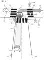
- FIG. 2A is a diagram showing an example of an image displayed on the display device 18.
- the image shown in FIG. 2A is a bird's-eye view image obtained when a virtual viewpoint is set diagonally upward behind the vehicle V and the front of the vehicle V is photographed from the position of the viewpoint.
- Information such as the lane and sign of the road on which the vehicle V is traveling, the traveling position of the vehicle V, and obstacles existing around the vehicle V is displayed on the bird's-eye image.
- the vehicle V will also be referred to as the own vehicle V to distinguish it from other vehicles.
- the image shown in FIG. 2A is a two-dimensional image created by computer graphics (CG)
- the image showing the driving environment of the vehicle V displayed on the display device 18 is not limited to this.
- the image showing the driving environment may be a three-dimensional image, or may be an image acquired by the imaging device 11.
- an image created by CG may be displayed superimposed on the image acquired by the imaging device 11.
- the driving scene shown in FIG. 2A corresponds to the actual driving scene of the vehicle V. That is, in the driving scene shown in FIG. 2A, the vehicle V is traveling on a road with one lane on each side.
- the driving direction of the vehicle in lane L1 is from the bottom to the top of the drawing (from the front side to the back side), and the driving direction of the vehicle in lane L2 is from the top side to the bottom of the drawing (from the back side to the near side).
- the direction is towards.
- the road on which the vehicle V is traveling intersects with a road with one lane on each side in front of the vehicle V.
- the traveling direction of the vehicle in lane L3 is from the left side to the right side in the drawing
- the traveling direction of the vehicle on lane L4 is from the right side to the left side in the drawing.
- intersection X the range where two roads intersect is intersection X. It is assumed that no traffic lights are installed at the intersection X shown in FIG. 2A. At the intersection Crosswalks C2 and C3 are provided for this purpose.
- a vehicle traveling in lane L1 can turn left or right at intersection X
- a vehicle traveling in lane L3 can go straight or turn right at intersection X
- a vehicle traveling in lane L4 can turn left or right at intersection X. be able to go straight or turn left.
- the navigation device 16 sets the driving route R of the vehicle V using the driving support function of the support unit 20.
- the navigation device 16 sets, for example, a travel route R shown in FIG. 2A.
- the driving route R is a route in which the vehicle goes straight in the lane L1, turns right at the intersection X, travels in the lane L3, and reaches the destination Px.
- the vehicle V is traveling along the driving route R in the lane L1, as shown in FIG. 2A.
- a pedestrian Y1 at a position P1 moves by walking from a position P1 to a position P2 and crosses a crosswalk C1
- a pedestrian Y2 at a position P3 moves from a position P3 to a position P4.
- the user moves by walking and crosses the crosswalk C3.
- another vehicle Z is stopped at a position P5 in front of the crosswalk C2 in the lane L3.
- the driving support device 19 uses the driving support function to drive the vehicle V to the destination Px while providing appropriate information to the occupants of the vehicle using the information providing device included as a part thereof. Executes driving support for driving.
- This driving support including information provision is mainly realized by the functions of the acquisition section 21, the recognition section 22, the determination section 23, and the notification section 24.
- the acquisition unit 21 has an intersection area acquisition function that acquires an intersection area where another moving object intersects with a movable area in the travel route R set by autonomous driving control.
- Other moving objects are traffic participants other than the vehicle V, such as other vehicles, motorcycles, bicycles, and pedestrians.
- the area in which other moving objects can move is an area in which traffic participants other than the vehicle V can move when moving from the current position to the destination.
- areas where pedestrians can move are areas where pedestrians can walk, such as sidewalks, crosswalks, and pedestrian bridges.
- the area in which other vehicles and motorcycles can move is the area on the road where they can travel, similar to the vehicle V.
- the driving support device 19 uses the intersection area acquisition function of the acquisition unit 21 to acquire the driving route R from the navigation device 16. Next, in the travel route R, an intersection area where another moving object intersects with a movable area is acquired. Traveling route R intersects with an area in which other moving objects can move if a traffic participant other than vehicle V is present in an area in which that traffic participant can move. When the vehicle V travels along this line, the vehicle V comes into contact with another moving body. In other words, when the travel route R of the vehicle V and the area where traffic participants other than the vehicle V can move exist on the same plane, and when viewed from above, the travel route R of the vehicle V is This refers to overlapping part or all of the area in which traffic participants can move.
- a crosswalk existing on the travel route R becomes a crossing area.
- a pedestrian bridge exists on the travel route R, even if the vehicle V travels along the travel route R while the pedestrian is walking on the pedestrian bridge, the relationship between the vehicle V and the pedestrian is There will be no contact. This is because the road on which the vehicle V travels and the pedestrian bridge on which the pedestrian walks do not exist on the same plane.
- the map information 14 includes road information of roads that the vehicle V passes when traveling along the travel route R. Furthermore, the map information 14 also includes information on areas on the road through which the vehicle V can move, where traffic participants other than the vehicle V can move, and their attributes. Therefore, the driving support device 19 can extract the intersection area existing on the travel route R using the intersection area acquisition function of the acquisition unit 21.
- intersection area examples include an intersection where a road on which the vehicle V is traveling and a road on which other vehicles other than the vehicle V are traveling, a crosswalk installed on the road on which the vehicle V is traveling, etc. .
- vehicle V enters a facility located in a position facing a road, if a sidewalk is provided between the roadway and the facility, the portion of the sidewalk facing the facility will be in the intersection area.
- a sidewalk is provided between the roadway and the facility
- the portion of the sidewalk facing the facility will be in the intersection area.
- Become In other words, when a pedestrian is walking on a sidewalk that exists between the facility and the roadway, when a vehicle V enters the facility, the vehicle V and the pedestrian will come into contact, so the sidewalk will be in the intersection area. becomes.
- the intersection X becomes an intersection area.
- the crosswalk C1 becomes a crossing area.
- the crosswalk C2 becomes the crossing area
- the crosswalk C3 becomes the crossing area.
- the recognition unit 22 has a driving environment recognition function that recognizes the driving environment around the vehicle V.
- the driving support device 19 uses the driving environment recognition function of the recognition unit 22 to acquire the detection results of the imaging device 11 and the distance measuring device 12, performs processing such as pattern matching and sensor fusion on the acquired detection results, and Recognize V's driving environment. For example, the driving support device 19 detects other vehicles traveling around the vehicle V based on the detection results of the imaging device 11, and determines the distance from the vehicle V to the other vehicle and the vehicle The direction in which the other vehicle exists with respect to V is detected, and the position of the other vehicle with respect to vehicle V is recognized.
- the driving support device 19 detects a pedestrian crossing the crosswalk in front of the vehicle V from the detection result of the imaging device 11, and detects a pedestrian crossing the crosswalk in front of the vehicle V from the detection result of the distance measuring device 12. The distance is detected and the position of the other vehicle with respect to the vehicle V is recognized.
- a traffic light may be installed at intersection X, which is a crossing area.
- the driving support device 19 uses the driving environment recognition function of the recognition unit 22 to determine whether a traffic light exists in front of the vehicle V from the detection results of the imaging device 11 and the map information 14. Determine whether or not. If it is determined that a traffic light exists in front of the vehicle V, the state of the traffic light is detected as the driving environment.
- the state of a traffic light is, for example, the state of the light of the traffic light. Specifically, the state of the traffic light is red (that is, the state where vehicle V must stop before intersection X), and the state where the traffic light is yellow.
- a light state that is, a state in which the vehicle V cannot enter the intersection X unless it is unable to stop
- a state in which the traffic light is blue that is, a state in which the vehicle V can enter the intersection X.
- the state of the traffic light is detected from an image acquired by the imaging device 11.
- the driving support device 19 uses the driving environment recognition function of the recognition unit 22 to recognize, for example, a preceding vehicle and a following vehicle traveling in lane L1, and an oncoming vehicle traveling in lane L2.
- the vehicle and vehicles traveling in lanes L3 and L4 are detected as other vehicles. Then, based on the direction and distance of the other vehicle with respect to the vehicle V, the position of the other vehicle traveling around the vehicle V is recognized.
- another vehicle Z that has stopped at a position P5 in front of the crosswalk C2 in the lane L3 is recognized as another vehicle that is traveling around the vehicle V.
- the driving support device 19 detects pedestrians crossing the crosswalks C1, C2, and C3, and recognizes the presence of pedestrians as the driving environment of the vehicle V. In the driving scene shown in FIG. 2A, pedestrian Y1 who is about to cross the crosswalk C1 and pedestrian Y2 who is about to cross the crosswalk C3 are detected. Recognized as a pedestrian. Furthermore, the driving support device 19 determines whether or not a traffic light is installed at the intersection X. In the driving scene shown in FIG. 2A, since no traffic light is installed at intersection X, it is recognized that no traffic light exists at intersection X.
- the determination unit 23 has a passage determination function that determines whether the vehicle V can pass through the intersection area based on the travel environment of the vehicle V recognized by the travel environment recognition function.
- the driving support device 19 uses the passage determination function of the determination unit 23 to determine whether or not an obstacle exists in the intersection area, and if it is determined that there is no obstacle in the intersection area, the vehicle V is allowed to cross the intersection area. It is determined that it is possible to pass. On the other hand, if it is determined that an obstacle exists in the intersection area, it is determined that the vehicle V cannot pass through the intersection area.
- the driving support device 19 uses the passage determination function of the determination unit 23 to determine whether a traffic light is installed in the intersection area (specifically, intersection X).
- the driving support device 19 acquires the position information of the traffic light from, for example, the map information 14, compares the position of the intersection area with the position of the traffic light, and determines whether a traffic light is installed in the intersection area. If it is determined that a traffic light is installed in the intersection area (specifically, intersection X), it is determined whether the traffic light is in a state that instructs the vehicle to stop.
- the state of the traffic light is a state instructing a stop (that is, a red light state)
- the state of the traffic light is not a state instructing a stop (in other words, If it is determined that the vehicle V is in a blue light state), it is determined that the vehicle V can pass through the intersection area.
- vehicle V can stop before intersection X based on the running state of vehicle V (particularly the running speed of vehicle V) and the distance from vehicle V to the intersection area (intersection X). Determine whether or not. If it is determined that the vehicle V cannot stop before the intersection X, the driving support device 19 determines that the traffic light is not in a state that instructs a stop and that the vehicle V can pass through the intersection area (intersection X). On the other hand, if it is determined that the vehicle V can stop before the intersection area (intersection It is determined that it is not possible.
- the driving support device 19 determines whether the obstacle is present in the intersection area or not. , and when it is determined that the traffic light is not in a state that instructs a stop, it is determined that the vehicle V can pass through the intersection area. On the other hand, if the driving support device 19 determines that an obstacle exists in the intersection area or if it determines that the traffic light is in a state that instructs a stop, the driving support device 19 determines that the vehicle V cannot pass through the intersection area. do.
- the determination of the presence or absence of an obstacle in the intersection area and the state of the traffic light may be performed at the same time, or the state of the traffic light may be determined first, and then the presence or absence of an obstacle in the intersection area may be determined. .
- the driving support device 19 recognizes that the intersection X and the crosswalks C1 and C2 are intersection areas, and that no traffic lights are installed at the intersection X. In the driving scene shown in FIG. 2A, since no traffic light is installed at the intersection X, the driving support device 19 determines the presence or absence of obstacles at the intersection X and the crosswalks C1, C2, and C3.
- the driving support device 19 detects the presence or absence of an obstacle when crossing the crosswalk C1 with another vehicle Z stopped at a position P5 in front of the crosswalk C2 in the lane L3 in the driving scene shown in FIG. 2A. It is recognized that there is a pedestrian Y1 who is about to cross the street and a pedestrian Y2 who is crossing the crosswalk C3. Based on this recognition, the driving support device 19 determines that pedestrians Y1 and Y2 are present at the crosswalks C1 and C3, respectively, and that the vehicle V cannot pass through the crosswalks C1 and C3.
- the driving support device 19 determines that there is a possibility that another parked vehicle Z will enter the crosswalks C1 to C3 and the intersection X. Therefore, in the driving scene shown in FIG. 2A, the driving support device 19 determines that the vehicle V cannot pass through the intersection area.
- the driving support device 19 uses the passage determination function of the determination unit 23 to determine whether a plurality of intersection areas exist at one point.
- the presence of a plurality of intersection areas at one point means, for example, the presence of a plurality of intersection areas adjacent to each other.
- the driving support device 19 determines that a plurality of intersection areas exist at one point.
- there is only one crosswalk at a location that is not a road intersection there are no adjacent crosswalks that are crosswalks, so there are multiple crosswalks at one point. It is determined that it does not exist.
- An example of where multiple intersection areas do not exist is a point where a crosswalk is installed in front of a facility facing the road for the convenience of facility users. It will be done.
- the notification unit 24 has a notification function that notifies an in-vehicle terminal and/or an electronic terminal in the vehicle V whether or not the vehicle V can pass through the intersection area.
- the in-vehicle terminal and electronic terminal of the vehicle V are, for example, the display device 18, but are not limited thereto, and are not limited to the display portion of the instrument panel, which provides information to the occupants of the vehicle V when executing the driving assistance of the above-mentioned assistance level 3 or 4. Including terminals for providing services.
- the driving support device 19 uses the notification function of the notification unit 24 to notify the occupants of the vehicle V whether or not the vehicle V can pass through the intersection area, using an on-vehicle terminal and/or an electronic terminal in the vehicle V. do.
- the driving support device 19 repeatedly performs the passage determination process using the passage determination function while the vehicle V travels from the current position to the intersection area. Then, the information provided to the in-vehicle terminal and/or electronic terminal (that is, the occupant of the vehicle V) in the vehicle V is changed according to the obtained determination result.
- the information that the driving support device 19 provides to the occupants of the vehicle V includes information indicating that it is determined whether or not an obstacle exists in the intersection area, and information indicating that it is determined whether or not an obstacle exists in the intersection area (i.e. Examples of information include information indicating the type of traffic participant), information indicating the lighting status of a traffic light installed in the intersection area, and information indicating whether the vehicle V can pass through the intersection area. These pieces of information are displayed on the display device 18 to show them to the occupants of the vehicle V, but instead, they may be output as audio from a speaker included in the display device 18.
- the occupant when the vehicle V is approaching an intersection area, the occupant is notified that the vehicle V is approaching the intersection area by a voice such as "We are almost at the intersection.” In addition to this, when the vehicle V can pass through an intersection area, the occupants are notified with a voice message such as "You can pass through the intersection ahead as is.” The audio will be recorded or synthesized.
- these pieces of information may be displayed together with the distance from the vehicle V to the intersection area. Alternatively or in addition to this, this information may be displayed at the position of the intersection area on the travel route R displayed on the display device 18. Alternatively or in addition to this, this information may be displayed superimposed on the image outside the vehicle acquired from the imaging device 11. Further, the display device 18 on which this information is displayed includes not only a display mounted on the vehicle V but also a display of a terminal owned by a passenger of the vehicle V.
- the driving support device 19 performs all driving tasks of the vehicle V and the supervisor monitors the running of the vehicle V at a remote location away from the vehicle V, as in an unmanned taxi, the above-mentioned
- the information may be displayed on a display included in a terminal for monitoring the running of the vehicle V.
- the driving support device 19 determines that the vehicle cannot pass through the crosswalk C1 because the pedestrian Y1 is present, as described above. Based on this determination result, the driving support device 19 uses the notification function of the notification unit 24 to notify the occupant of the vehicle V that the vehicle V cannot pass the crosswalk C1 and therefore will stop in front of the crosswalk C1. The driving support device 19 notifies the occupant that the vehicle will stop before the crosswalk C1, for example, by changing the color of the display portion of the driving route R displayed on the display device 18. In the driving route R shown in FIG.
- the part up to this side of the crosswalk C1 is lightly hatched as a driveable part, and the crosswalk C1 and the crosswalk C1 The area beyond is marked with dark hatching to indicate the area where it is impossible to drive.
- the driving support device 19 displays an image (icon) I1 labeled "STOP" shown in FIG. 2A on the display device 18 to notify the occupants that the vehicle V will stop before the crosswalk C1. Notice.
- the position where the image I1 is displayed is the position of the intersection X on the driving route R displayed on the display device 18.
- the driving support device 19 outputs a voice message from the speaker of the display device 18 saying, "Stop before the crosswalk ahead," and the vehicle V Notify passengers that the vehicle will stop before the vehicle.
- the driving support device 19 notifies the occupant by the above-mentioned display and audio that the vehicle will stop before the crosswalk C1, and then uses the driving support function of the support unit 20 to cause the vehicle V to travel along the travel route R.
- the running speed of the vehicle V is controlled via the vehicle speed control device 171 of the vehicle control device 17, and the vehicle V is stopped in front of the crosswalk C1.
- the steering control device 172 is also controlling the steering wheel of the vehicle V.
- FIG. 2B is an example of an image displayed on the display device 18 when the vehicle V stops in front of the crosswalk C1.
- pedestrian Y1 is walking at position P1a of crosswalk C1 toward position P2.
- pedestrian Y2 is walking toward position P4 at position P3a of crosswalk C3.
- the driving support device 19 recognizes the positions of pedestrians Y1 and Y2 from the detection results of the imaging device 11 and the distance measuring device 12.
- the driving support device 19 determines that the vehicle V cannot pass through the crosswalks C1 and C3 because pedestrians Y1 and Y2 are present at each of the crosswalks C1 and C3.
- the driving support device 19 controls the running operation of the vehicle V via the vehicle control device 17 so that the vehicle V is maintained in a stopped state.
- the driving support device 19 recognizes the other vehicle Z stopped at position P5, and also recognizes that in the driving scene shown in FIG. 2B, the other vehicle Z continues to stop at the same position P5 as in the driving scene shown in FIG. 2A. Guess the factors.
- the driving support device 19 estimates that the vehicle has stopped before the crosswalk C2 in order to avoid stopping at the intersection X. If another vehicle Z goes straight through intersection X, it will stop before crosswalk C3 to avoid contact with pedestrian Y2, and if another vehicle Z turns right at intersection In order to avoid contact with pedestrians, you must stop before the C1 crosswalk. In other words, the other vehicle Z will stop at the intersection X whether it is going straight or turning right.
- FIG. 2C is an example of an image displayed on the display device 18 after the vehicle V has stopped in front of the crosswalk C1 and after the pedestrians Y1 and Y2 have finished crossing the crosswalks C1 and C3, respectively.
- pedestrian Y1 is walking at position P2
- pedestrian Y2 is walking at position P4.
- the driving support device 19 recognizes the positions of pedestrians Y1 and Y2 from the detection results of the imaging device 11 and the distance measuring device 12. The driving support device 19 then determines that the vehicle V can pass through the crosswalks C1 and C3 because there are no obstacles on the crosswalks C1 and C3.
- the driving support device 19 recognizes the other vehicle Z that is stopped at the position P5, and determines whether the other vehicle Z starts and enters the intersection X in the driving scene shown in FIG. 2C.
- the driving support device 19 stops the other vehicle Z in front of the crosswalk C2 because it is necessary to stop inside the intersection X to avoid contact with pedestrians Y1 and Y2. I guessed that it was.
- pedestrians Y1 and Y2 have finished crossing the crosswalk, and other vehicle Z needs to stop at intersection X to avoid contact with pedestrians Y1 and Y2. do not have. Therefore, the driving support device 19 determines that the other vehicle Z starts and enters the intersection X. On the other hand, if obstacles other than pedestrians Y1 and Y2 exist at the intersection judge.
- the driving support device 19 autonomously controls the driving operation of the vehicle V via the vehicle control device 17 so that the vehicle V departs after the other vehicle Z passes the intersection X, as described above. do. This is to reliably avoid contact between the vehicle V and another vehicle Z.
- the occupant of vehicle V has an expectation that vehicle V will depart once pedestrians Y1 and Y2 have finished crossing the crosswalk. Since no traffic lights are installed at the intersection X shown in FIG. This is because we think that we can pass through X.
- the occupant of the vehicle V is such that the pedestrian Y1 moves on foot from the position P1a shown in FIG.
- the image I1 notifying the occupants that the vehicle V has stopped remains displayed on the display device 18, and the vehicle V has not stopped. continue.
- the driving support device 19 determines that the other vehicle Z will enter the intersection X, and performs control to cause the vehicle V to depart after the other vehicle Z has passed the intersection X.
- the occupants of the vehicle V think that because the vehicle V continues to stop contrary to their expectations, the autonomous driving control by the driving support device 19 is not being executed appropriately, and as a result, the vehicle V is stopped. I feel uneasy about it.
- intersection Judgments need to be made in a relatively short time. This is because the vehicle V cannot depart unless it is determined that all the intersection areas are passable. Therefore, in a driving scene as shown in FIG. 2C, it is difficult for the occupant of the vehicle V to intuitively grasp the cause of the vehicle V stopping, and the occupant is likely to feel uneasy. Further, when the departure of the other vehicle Z is delayed, or when the other vehicle Z is a parked vehicle, the departure of the vehicle V is delayed, and the occupants of the vehicle V feel anxious.
- the notification unit 24 of the present embodiment provides a system in which the stoppage time of the vehicle V is longer than a predetermined time when the determination unit 23 determines that the vehicle V cannot pass through the intersection area.
- the time When the time is long, it has a function of notifying the occupants of the vehicle V of the reason why the vehicle V cannot pass through the intersection area.
- the driving support device 19 uses the notification function of the notification unit 24 to acquire the stopping time of the vehicle V. If the stopping time of the vehicle V is longer than a predetermined time, the occupants of the vehicle V are notified of the reason why the vehicle V cannot pass through the intersection area. On the other hand, if the stopping time of the vehicle V is less than or equal to the predetermined time, the occupant of the vehicle V is not notified of the reason why the vehicle V cannot pass through the intersection area.
- the stopping time of the vehicle V refers to the time that has passed since the vehicle V stopped before an intersection area that was determined to be impassable. Whether the vehicle V is stopped is determined based on, for example, the traveling speed of the vehicle V acquired from the state detection device 13 and the position information of the vehicle V acquired from the position detection device 15. Specifically, when the traveling speed of the vehicle V obtained from the state detection device 13 is 0 km/h and the position information of the vehicle V obtained from the position detection device 15 has not changed, the vehicle V is stopped. It is determined that there is.
- the driving support device 19 stores in the RAM 193 or the like the time point when the driving support function of the support unit 20 determines that the vehicle V has stopped. Then, if necessary, the time that has passed since it was determined that the vehicle V has stopped is acquired as the stopping time.
- the predetermined time period which is the standard for notifying the cause of the stoppage, is set to an appropriate value within a range that does not make the occupants of the stopped vehicle V feel uneasy when the occupants of the vehicle V cannot grasp the cause of the stoppage of the vehicle V. can.
- a predetermined time is set to be a general time period when a traffic light is in a state instructing a stop (that is, a red light state). Instead, the stop time required for passing through each intersection area is recorded, and the average value of the stop times recorded for each intersection area is set to a predetermined time.
- the amount of time that passengers can wait for departure without feeling anxious is determined in advance through an experiment, and the stopping time determined from the experiment is set to a predetermined time.
- the factor that prevents the vehicle V from passing through the intersection area is another moving object that exists in the intersection area where it is determined that the vehicle V cannot pass through. For example, bicycles and pedestrians walking at a crosswalk, other vehicles and motorcycles existing at an intersection, etc.
- the driving support device 19 uses the notification function of the notification unit 24 to notify the cause of the inability of the vehicle V to pass through the intersection area, the driving support device 19 displays the display portion of the other vehicle Z as a broken-line rectangular image, as shown in FIG. 2C, for example. Highlight and display with I2. In this manner, when the display device 18 is used to notify the cause of the inability of the vehicle V to pass through the intersection area, the driving support device 19 changes the color of the display portion of the cause to emphasize it. Alternatively or in addition to this, the driving support device 19 surrounds the display portion of the factor with a rectangular or circular image.
- the driving support device 19 outputs a voice from the speaker of the display device 18 saying, "We are stopped due to another vehicle Z on the left side in front,” and notifies the occupants of the cause of the stop. do.
- the driving support device 19 changes the original color to a color (for example, red) that draws more attention.
- the driving support device 19 When notifying that the cause is that the vehicle V cannot pass through the intersection X, the driving support device 19 continues to notify the cause until it is determined that the vehicle V can pass through the intersection area.
- the other vehicle Z passes through the intersection X, and until it is determined that the vehicle V can enter the intersection X, the other vehicle Z is displayed with increased emphasis in the image I2. Additionally, if there are multiple factors that prevent the vehicle V from passing through the intersection area, it is determined for each factor whether or not the vehicle V can pass through the intersection area, and notification of each factor is notified according to the determination result for each factor. Continue. For example, in the driving scene shown in FIG.
- pedestrian Y1 and other vehicle Z may Determine whether the object will become an obstacle. Then, while it is determined that the pedestrian Y1 and the other vehicle Z are the factors that prevent the vehicle V from passing through the intersection X, they continue to be displayed in an emphasized manner. After that, if it is determined that pedestrian Y1 does not become an obstacle when entering intersection X, and other vehicle Z is the only factor that prevents vehicle V from passing through intersection , and continue to highlight and display only the other vehicle Z.
- the driving support device 19 uses the notification function of the notification unit 24 to notify the cause of the vehicle V not being able to pass through the intersection area using the display device 18, the driving support device 19 uses the notification function of the notification unit 24 to notify the cause of the vehicle V not being able to pass through the intersection area.
- the contrast with respect to the display portion around the traveling route R is lowered.
- the driving support device 19 increases the contrast of the displayed portion of the intersection region with respect to the displayed portion of the travel route R.
- the driving support device 19 increases the degree of emphasis of the displayed portion of the intersection area. For example, in the driving scene shown in FIG.
- the contrast of the displayed portion of the driving route R beyond the crosswalk C3 with respect to the displayed portion of the lane L3 is lowered.
- the contrast of the display portions of the crosswalks C1 and C3 and the intersection X with respect to the driving route R is increased, and the degree of emphasis is increased by enclosing them in rectangular images.
- the driving support device 19 lowers the contrast of the displayed portion of the intersection area with respect to the displayed portion of the travel route R, and increases the degree of emphasis of the displayed portion of the cause of the vehicle V not being able to pass through the intersection area.
- the contrast of the displayed portions of the crosswalks C1 and C3 and the intersection X is lowered with respect to the displayed portion of the driving route R while increasing the degree of emphasis of the other vehicle Z in the image I2.
- the driving support device 19 stops the vehicle V when it is determined that the vehicle V cannot pass through the intersection area.
- the notification of the cause may be started from the time when the time exceeds a predetermined time.
- the driving support device 19 uses the driving environment recognition function of the recognition unit 22 to classify the obstacle into stationary obstacles and other obstacles. Stationary obstacles and other obstacles may be notified in different ways.
- a stationary obstacle is an obstacle that is placed in place and does not move itself. If a stationary obstacle is the cause of the stoppage, the vehicle V cannot continue traveling along the travel route R unless the stationary obstacle is avoided. prompt the vehicle occupants and others to take maneuvers to avoid obstacles.
- FIG. 2D is an example of an image displayed on the display device 18 when another vehicle Z has started and is passing through the crosswalk C2, the intersection X, and the crosswalk C3.
- the other vehicle Z starts from position P5 and travels straight through intersection X to position P6. It is assumed that pedestrians Y1 and Y2 are walking outside the screen of the display device 18.
- the driving support device 19 recognizes that the other vehicle Z is traveling at the position P6 from the detection results of the imaging device 11 and the distance measuring device 12, and determines that the other vehicle Z has passed through the intersection X. .
- the driving support device 19 determines that the vehicle V can pass through the intersection area, it changes the display portion of the intersection area on the display device 18. Instead or in addition to this, the driving support device 19 superimposes a message on the display portion of the intersection area to indicate that the intersection area is passable. In the driving scene shown in FIG. 2D, for example, the degree of emphasis on the displayed portion of the intersection X is reduced, and an image indicating that the intersection X is passable is displayed superimposed on the displayed portion of the intersection X. Instead or in addition to this, the color of the display portion of the travel route R is changed. For example, the color of the displayed portion of the driving route R shown in FIG. 2D is changed from dark hatching indicating areas where travel is not possible to light hatching indicating areas where travel is possible.
- FIG. 2E shows an example of the driving route R in which the color of the display part has been changed.
- vehicle V starts from a stopping position in front of crosswalk C1 and enters intersection X.
- the driving support device 19 causes the vehicle V to travel along the travel route R using the driving support function of the support unit 20.
- the vehicle V passes through the intersection X and the crosswalks C1 and C3 under the control of the drive device and the steering device via the vehicle control device 17, and reaches the destination Px under autonomous driving control.
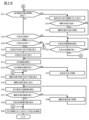
- FIGS. 3A to 3D are examples of flowcharts showing information processing executed in the driving support system 10 of this embodiment. The processing described below is executed at predetermined time intervals by the CPU 191, which is the processor of the driving support device 19.
- step S1 of FIG. 3A the intersection area acquisition function acquires the travel route R from the navigation device 16, and in the subsequent step S2, the area in which other moving objects can move is acquired from the map information 14.
- step S3 an intersection area is acquired.
- step S4 the current position of the vehicle V is acquired from the position detection device 15 by the driving environment recognition function, and in the subsequent step S5, the driving route R is displayed on the display device 18 by the notification function.
- step S6 it is determined by autonomous driving control whether the vehicle V can travel to the intersection area.
- step S7 If it is determined by the autonomous driving control that the vehicle V cannot travel to the intersection area, such as when there is an unavoidable obstacle in front of the vehicle V, the execution of the routine ends and the driver shifts to manual driving. On the other hand, if it is determined that the vehicle V can travel to the intersection area by the autonomous driving control, the process proceeds to step S7.
- step S7 the notification function displays on the display device 18 that it is possible to drive up to the intersection area, and in the subsequent step S8, the driving support function causes the vehicle V to move along the set travel route R. run.
- step S9 it is determined whether the distance from the vehicle V to the intersection area is less than or equal to a predetermined distance. If it is determined that the distance from the vehicle V to the intersection area is longer than the predetermined distance, the process proceeds to step S8, and the vehicle V is moved along the travel route R until the distance from the vehicle V to the intersection area becomes less than or equal to the predetermined distance. Keep it running. On the other hand, if it is determined that the distance from the vehicle V to the intersection area is less than or equal to the predetermined distance, the process proceeds to step S10.
- step S10 the passage determination function determines whether a traffic light is installed in the intersection area. If it is determined that a traffic light is installed in the intersection area, the process advances to step S21 in FIG. 3B. On the other hand, if it is determined that no traffic light is installed in the intersection area, the process advances to step S51 in FIG. 3C. In the following description, it is assumed that the intersection area determined to have a traffic light installed is an intersection X where a crosswalk is installed.
- step S10 of FIG. 3A determines whether a traffic light is installed in the intersection area. If it is determined in step S10 of FIG. 3A that a traffic light is installed in the intersection area, the process proceeds to step S21 of FIG. 3B.
- step S21 of FIG. 3B the passage determination function determines whether the state of the traffic light indicates a stop. If it is determined that the traffic light is instructing a stop, the process proceeds to step S22, and the vehicle V is caused to travel along the set travel route R. In the following step S23, it is determined whether the vehicle V has reached the crosswalk, and if it is determined that the vehicle V has not reached the crosswalk, the process proceeds to step S21, and the vehicle V starts traveling along the travel route R. The state of the traffic light is detected while continuing. On the other hand, if it is determined that the vehicle V has reached the crosswalk, the process proceeds to step S24 and the vehicle V is stopped in front of the crosswalk. After that, the process advances to step S21, and the state of the traffic light is detected
- step S21 If it is determined in step S21 that the state of the traffic light does not instruct the vehicle to stop, the process proceeds to step S25.
- step S25 it is determined whether the vehicle V is going straight through the intersection X. If it is determined that the vehicle V will go straight through the intersection X, the process proceeds to step S26, in which obstacles present at the intersection do. If it is determined that the vehicle V can pass through the intersection X, the process proceeds to step S40, where the vehicle V is caused to travel along the travel route R and pass through the intersection X. On the other hand, if it is determined that the vehicle V cannot pass through the intersection X, the process proceeds to step S26 and the obstacle detection is repeated. Note that when the vehicle V reaches the intersection X, the vehicle V is stopped in front of the intersection X.
- step S25 determines whether the vehicle V will turn right at the intersection X. If it is determined that the vehicle V will turn right at the intersection X, the process advances to step S29. On the other hand, if it is determined that the vehicle V does not turn right (that is, turns left) at the intersection X, the process advances to step S34.
- step S29 the notification function displays on the display device 18 that it is possible to drive to the center of the intersection X
- step S30 the driving support function causes the vehicle V to drive to the center of the intersection X.
- step S31 the driving environment recognition function detects an oncoming vehicle based on the detection results of the imaging device 11 and the distance measuring device 12, and in the subsequent step S32, it is determined whether the oncoming lane is passable. If it is determined that there is no oncoming vehicle and the oncoming lane is passable, the process advances to step S34. On the other hand, if it is determined that there is an oncoming vehicle and the oncoming lane is not passable, the process proceeds to step S33 and the vehicle V is stopped at the center of the intersection X. Then, the process advances to step S31, and an oncoming vehicle is detected again.
- step S34 the notification function displays on the display device 18 that it is possible to travel to a position in front of the crosswalk.
- step S35 the vehicle V is driven to a position in front of the crosswalk.
- step S36 pedestrians and bicycles passing through the crosswalk are detected, and in step S37, it is determined whether or not the crosswalk is passable. If it is determined that there are no pedestrians or bicycles and the crosswalk is passable, the process proceeds to step S39, where the display device 18 displays that the intersection X is passable, and then the process proceeds to step S40.
- step S38 the process proceeds to step S38, and the vehicle V is stopped at a position in front of the crosswalk. Then, the process advances to step S36, and pedestrians and bicycles are detected again.
- step S51 of FIG. 3C the passage determination function determines whether a plurality of intersection areas exist in front of the vehicle V. If it is determined that a plurality of intersection areas exist in front of the vehicle V, the process advances to step S61 in FIG. 3D. On the other hand, if it is determined that there are no multiple intersection areas in front of the vehicle V, the process advances to step S52. In step S52, the driving environment recognition function detects an obstacle present in the intersection area, and in the subsequent step S53, the passage determination function determines whether or not the intersection area is passable.
- step S56 the notification function displays on the display device 18 that the intersection area is passable
- step S57 the driving support function displays the information that the intersection area is passable.
- the vehicle V is driven to pass through the intersection area.
- step S54 it is determined whether it is necessary to stop before the intersection area. If it is determined that the vehicle does not need to stop, the process proceeds to step S52 and the obstacle detection is performed again. On the other hand, if it is determined that it is necessary to stop, the process proceeds to step S55, where the vehicle V is stopped in front of the intersection area, and the process proceeds to step S52.
- step S61 of FIG. 3D the driving environment recognition function detects an obstacle present in the intersection area, and in the subsequent step S62, the passage determination function determines whether or not the intersection area is passable. If it is determined that the intersection area is passable, the process proceeds to step S69, where the notification function displays on the display device 18 that the intersection area is passable, and in subsequent step S70, the driving support function displays the information that the intersection area is passable. , the vehicle V is driven to pass through the intersection area.
- step S63 it is determined whether it is necessary to stop before the intersection area. If it is determined that the vehicle does not need to stop, the process advances to step S61 and the obstacle detection is performed again. On the other hand, if it is determined that it is necessary to stop, the process proceeds to step S64, and the vehicle V is stopped in front of the intersection area.
- step S65 the notification function determines whether the vehicle V has stopped for a longer time than a predetermined time. If it is determined that the stopping time of the vehicle V is longer than the predetermined time, the process proceeds to step S66, and the obstacles in the intersection area are classified into stationary obstacles and other obstacles, and in the subsequent step S67, the stopping time of the vehicle V is determined to be longer than the predetermined time. The cause of the stop is recognized and the cause of the stop is displayed on the display device 18 in step S68. After that, the process advances to step S61, and obstacle detection is performed again. On the other hand, if it is determined that the stopping time of the vehicle V is less than or equal to the predetermined time, the process advances to step S61 and the obstacle detection is performed again.
- the present embodiment includes an acquisition unit 21 that acquires an intersection region where another moving object intersects with a movable region in a travel route R set by autonomous driving control, and a travel environment around the vehicle V. a recognition unit 22 that recognizes, a determination unit 23 that determines whether the vehicle V can pass through the intersection area based on the driving environment, and a determination unit 23 that determines whether the vehicle V can pass through the intersection area. If it is determined that this is not possible, and the stopping time of the vehicle V is longer than a predetermined time, the onboard terminal and/or electronic terminal in the vehicle V is notified of the reason why the vehicle V cannot pass through the intersection area.
- An information providing device is provided, which includes a notification section 24 that provides information. Thereby, it is possible to suppress the anxiety felt by the occupants before the vehicle V departs.
- the notification unit 24 when notifying the cause using the display device 18, the notification unit 24 adjusts the contrast of the display portion of the intersection area with respect to the display portion of the travel route R. At the same time, the degree of emphasis of the displayed portion of the factor is increased. Thereby, the occupant of the vehicle V can intuitively grasp the reason why the vehicle V stops.
- the notifying unit 24 determines that the stopping time exceeds the predetermined time. Notification of the above-mentioned factors will begin from the time when Thereby, it is possible to suppress excessively emphasizing and displaying the cause of the vehicle V stopping and giving the occupants of the vehicle V a sense of discomfort.
- the notification unit 24 displays the intersection area on the display device 18. changing a portion, or superimposing a message on the display portion of the intersection region that the intersection region is passable. Thereby, the occupant of the vehicle V can intuitively understand that the vehicle V can pass through the intersection area.
- the notification unit 24 when notifying the cause using the display device 18, displays a portion of the display portion of the travel route R beyond the intersection area. , lowering the contrast with respect to the display portion around the travel route R, increasing the contrast of the display portion of the intersection area with respect to the display portion of the travel route R, and increasing the degree of emphasis of the display portion of the intersection area. Do at least one of the following: Thereby, the occupant of the vehicle V can intuitively grasp the reason why the vehicle V stops.
- the notification unit 24 when notifying the cause using the display device 18, changes the color of the display portion of the cause and displays the cause. Execute at least one of enclosing the part in a rectangle or a circle. Thereby, the occupant of the vehicle V can intuitively grasp the reason why the vehicle V stops.
- the recognition unit 22 classifies the obstacle into a stationary obstacle and other obstacles, and the notifying unit 24 notifies the stationary obstacles and other obstacles in different ways. Thereby, the occupant of the vehicle V can be prompted to perform a driving operation to avoid the stationary obstacle.
- the notification unit 24 continues to notify the cause until the determination unit 23 determines that the vehicle V can pass through the intersection area. Thereby, the occupant of the vehicle V can be notified of the cause of the stoppage more reliably.
- the determination unit 23 determines for each factor whether or not the vehicle V can pass through the intersection area, The notification unit 24 continues to notify each factor according to the determination result of the determination unit 23. This makes it possible to receive notifications for each cause of a stop.
- the notification unit 24 includes a display mounted on the vehicle V, a display provided on a terminal for monitoring the running of the vehicle V, and a display on a terminal of an occupant of the vehicle. The factors are displayed on at least one of the displays. As a result, the person who supervises the running of the vehicle can also be notified of the cause of the stoppage.
- the present embodiment is an information providing method executed using a processor, in which the processor acquires an intersecting area where another moving object intersects with a movable area in a driving route R set by autonomous driving control. , if the driving environment around the vehicle V is recognized, and based on the driving environment it is determined whether the vehicle V can pass through the intersection area, and if it is determined that the vehicle V cannot pass through the intersection area; and an information providing method of notifying an in-vehicle terminal and/or an electronic terminal in the vehicle V of the cause of the inability of the vehicle V to pass through the intersection area when the vehicle V is stopped for a longer time than a predetermined time. I will provide a. Thereby, it is possible to suppress the anxiety felt by the occupants before the vehicle V departs.
- Driving support system 11... Imaging device 12... Distance measuring device 13... State detection device 14... Map information 15... Position detection device 16... Navigation device 17... Vehicle control device 171... Vehicle speed control device 172... Steering control device 18... Display Device 19...Driving support device (information providing device) 191...CPU (processor) 192...ROM 193...RAM 20... Support unit 21... Acquisition unit 22... Recognition unit 23... Judgment unit 24... Notification unit C1, C2, C3... Crosswalk I1, I2... Image L1, L2, L3, L4...
Landscapes
- Engineering & Computer Science (AREA)
- Transportation (AREA)
- Mechanical Engineering (AREA)
- Automation & Control Theory (AREA)
- Chemical & Material Sciences (AREA)
- Combustion & Propulsion (AREA)
- Human Computer Interaction (AREA)
- Traffic Control Systems (AREA)
Abstract
According to the present invention, provided are an information providing device and an information providing method that acquire an intersection area, which intersects with an area allowing another moving object to move, on a travel route (R) set by autonomous travel control, recognize a travel environment around a vehicle (V), determine, on the basis of the recognized travel environment, whether or not the vehicle (V) is allowed to pass through the intersection area, and, if it is determined that the vehicle (V) is not allowed to pass through the intersection area, when stoppage time of the vehicle (V) is longer than a predetermined time, notify an on-vehicle terminal and/or an electronic terminal in the vehicle (V) of the factor that prevents the vehicle (V) from passing through the intersection area.
Description
本発明は、情報提供装置及び情報提供方法に関するものである。
The present invention relates to an information providing device and an information providing method.
自動運転機能を有する車両の停車状態を表示する場合に、車両の周囲状況を検出し、車両が自動運転中に周囲状況において将来的に停車状態となるときは、周囲状況の路面から上方に延出し、車両の停止理由を示す停止表示を表示装置に表示させることが知られている(特許文献1)。
When displaying the stopped state of a vehicle with an autonomous driving function, the surrounding situation of the vehicle is detected, and if the vehicle becomes stopped in the future in the surrounding situation while autonomously driving, a display that extends upward from the road surface of the surrounding situation is detected. It is known to cause a display device to display a stop display indicating the reason for stopping the vehicle (Patent Document 1).
上記従来技術では、車両の乗員に対して通知される停止理由が、交通法規、道路標識及び信号機の状態に応じたものに限られるため、交通法規、道路標識及び信号機の状態と異なる、たとえば障害物を要因として車両が停車した場合は、乗員に対して停止理由が通知されない。そのため、上記従来技術には、車両の乗員が、停車の要因を何ら示されないまま発車まで待つことになり、不安を感じるという問題がある。
In the above conventional technology, the reasons for stopping that are notified to vehicle occupants are limited to those based on traffic regulations, road signs, and traffic lights. When a vehicle stops due to an object, the occupants are not notified of the reason for the stop. Therefore, the above-mentioned conventional technology has a problem in that the occupants of the vehicle have to wait until the vehicle departs without being informed of the cause of the stoppage, which makes them feel uneasy.
本発明が解決しようとする課題は、車両が発車するまでに乗員が感じる不安を抑制できる情報提供装置及び情報提供方法を提供することである。
The problem to be solved by the present invention is to provide an information providing device and an information providing method that can suppress the anxiety felt by the occupants before the vehicle departs.
本発明は、自律走行制御により設定された走行経路において、他の移動体が移動可能な領域と交わる交差領域を取得し、車両の周囲の走行環境を認識し、認識した走行環境に基づいて、車両が交差領域を通過できるか否かを判定し、車両が交差領域を通過できないと判定した場合に、車両の停車時間が所定時間より長いときは、車両内の車載端末及び/又は電子端末に対して、車両が交差領域を通過できない要因を通知することによって上記課題を解決する。
The present invention acquires intersecting areas where other moving objects intersect with movable areas in a driving route set by autonomous driving control, recognizes the driving environment around the vehicle, and based on the recognized driving environment, It is determined whether the vehicle can pass through the intersection area, and when it is determined that the vehicle cannot pass through the intersection area, if the vehicle stoppage time is longer than a predetermined time, the in-vehicle terminal and/or electronic terminal in the vehicle is activated. On the other hand, the above problem is solved by notifying the cause of the vehicle not being able to pass through the intersection area.
本発明によれば、車両が発車するまでに乗員が感じる不安を抑制できる。
According to the present invention, the anxiety felt by the occupants before the vehicle departs can be suppressed.
以下、本発明の実施形態を図面に基づいて説明する。なお、以下の説明は、左側通行の法規を有する国で、車両が左側通行で走行することを前提とする。右側通行の法規を有する国では、車両が右側通行で走行するため、以下の説明の左と右を対称にして読み替えるものとする。
Hereinafter, embodiments of the present invention will be described based on the drawings. The following explanation assumes that vehicles drive on the left in countries that have left-hand traffic laws. In countries that have right-hand traffic laws, vehicles drive on the right-hand side, so the left and right directions in the following explanation should be interpreted symmetrically.
[運転支援システムの構成]
図1は、本発明に係る運転支援システム10を示すブロック図である。運転支援システム10は車載システムであり、自律走行制御により、車両の乗員(ドライバーを含む)により設定された目的地まで車両を走行させる。自律走行制御とは、後述する運転支援装置を用いて車両の走行動作を自律的に制御することをいい、当該走行動作には、加速、減速、発進、停車、右方向又は左方向への転舵、車線変更、幅寄せなど、あらゆる走行動作が含まれる。また、自律的に走行動作を制御するとは、運転支援装置が、車両の装置を用いて走行動作の制御を行うことをいう。つまり、運転支援装置は、予め定められた範囲内でこれらの走行動作に介入し、制御する。介入されない走行動作については、ドライバーによる手動の操作が行われる。 [Driving support system configuration]
FIG. 1 is a block diagram showing a driving support system 10 according to the present invention. The driving support system 10 is an in-vehicle system that uses autonomous driving control to drive the vehicle to a destination set by the occupants of the vehicle (including the driver). Autonomous driving control refers to autonomously controlling the driving behavior of a vehicle using a driving support device (described later), and the driving behavior includes acceleration, deceleration, starting, stopping, and turning to the right or left. This includes all driving movements, such as steering, changing lanes, and pulling alongside. Moreover, autonomously controlling the driving operation means that the driving support device controls the driving operation using a device of the vehicle. In other words, the driving support device intervenes and controls these driving operations within a predetermined range. Driving operations that do not require intervention are manually operated by the driver.
図1に示すように、運転支援システム10は、撮像装置11、測距装置12、状態検出装置13、地図情報14、位置検出装置15、ナビゲーション装置16、車両制御装置17、表示装置18、及び運転支援装置19を備える。また、図1に示すように、本実施形態の運転支援装置19は、その一部として、情報提供機能を有する情報提供装置を含む。運転支援システム10を構成する装置は、CAN(Controller Area Network)その他の車載LANによって接続され、互いに情報を授受できる。
As shown in FIG. 1, the driving support system 10 includes an imaging device 11, a distance measuring device 12, a state detection device 13, a map information 14, a position detection device 15, a navigation device 16, a vehicle control device 17, a display device 18, and A driving support device 19 is provided. Further, as shown in FIG. 1, the driving support device 19 of this embodiment includes, as a part thereof, an information providing device having an information providing function. The devices constituting the driving support system 10 are connected via a CAN (Controller Area Network) or other in-vehicle LAN, and can exchange information with each other.
撮像装置11は、画像により車両の周囲の対象物を認識する装置であり、たとえば、CCDなどの撮像素子を備えるカメラ、超音波カメラ、赤外線カメラなどのカメラである。撮像装置11は、一台の車両に複数を設けることができ、たとえば、車両のフロントグリル部、左右ドアミラーの下部及びリアバンパ近傍に配置できる。これにより、車両の周囲の対象物を認識する場合の死角を減らすことができる。
The imaging device 11 is a device that recognizes objects around the vehicle using images, and is, for example, a camera equipped with an imaging device such as a CCD, an ultrasonic camera, an infrared camera, or the like. A plurality of imaging devices 11 can be provided in one vehicle, and can be arranged, for example, in the front grille of the vehicle, below the left and right door mirrors, and near the rear bumper. This can reduce blind spots when recognizing objects around the vehicle.
測距装置12は、車両と対象物との相対距離および相対速度を演算するための装置であり、たとえば、レーザーレーダー、ミリ波レーダーなど(LRFなど)、LiDAR(light detection and ranging)ユニット、超音波レーダーなどのレーダー装置又はソナーである。測距装置12は、一台の車両に複数設けることができ、たとえば、車両の前方、右側方、左側方及び後方に配置できる。これにより、車両の周囲の対象物との相対距離及び相対速度を正確に演算できる。
The distance measuring device 12 is a device for calculating the relative distance and relative speed between the vehicle and the target object, and includes, for example, a laser radar, a millimeter wave radar, etc. (LRF, etc.), a LiDAR (light detection and ranging) unit, a super A radar device such as a sonic radar or a sonar. A plurality of distance measuring devices 12 can be provided in one vehicle, and can be arranged, for example, at the front, right side, left side, and rear of the vehicle. Thereby, the relative distance and relative speed of the vehicle to surrounding objects can be calculated accurately.
撮像装置11及び測距装置12にて検出する対象物は、道路の車線境界線、中央線、路面標識、中央分離帯、ガードレール、縁石、高速道路の側壁、道路標識、信号機、横断歩道、工事現場、事故現場、交通制限などである。また、対象物には、自車両以外の自動車(他車両)、自動二輪車(オートバイ)、自転車、歩行者など、車両の走行に影響を与える可能性がある障害物も含まれている。撮像装置11及び測距装置12の検出結果は、必要に応じて、運転支援装置19により所定の時間間隔で取得される。
Objects detected by the imaging device 11 and distance measuring device 12 include road lane boundaries, center lines, road signs, median strips, guardrails, curbs, expressway side walls, road signs, traffic lights, crosswalks, and construction work. These include the scene, accident scene, and traffic restrictions. The objects also include obstacles that may affect the running of the vehicle, such as cars other than the own vehicle (other vehicles), motorcycles, bicycles, and pedestrians. The detection results of the imaging device 11 and the distance measuring device 12 are acquired by the driving support device 19 at predetermined time intervals as necessary.
また、撮像装置11及び測距装置12の検出結果は、運転支援装置19にて統合又は合成(いわゆるセンサフュージョン)することができ、これにより、検出した対象物の不足する情報を補完できる。たとえば、位置検出装置15により取得した、車両が走行する位置である自己位置情報と、車両と対象物の相対位置(距離と方向)とにより、運転支援装置19にて対象物の位置情報を算出できる。算出された対象物の位置情報は、運転支援装置19にて、撮像装置11及び測距装置12の検出結果、並びに地図情報14などの複数の情報と統合され、車両の周囲の走行環境情報となる。また、撮像装置11及び測距装置12の検出結果と、地図情報14とを用いて、車両の周囲の対象物を認識し、その動きを予測することもできる。
Further, the detection results of the imaging device 11 and the distance measuring device 12 can be integrated or synthesized (so-called sensor fusion) in the driving support device 19, thereby complementing missing information about the detected object. For example, the driving support device 19 calculates the position information of the object based on the self-position information, which is the position where the vehicle is traveling, acquired by the position detection device 15 and the relative position (distance and direction) of the vehicle and the object. can. The calculated object position information is integrated with multiple pieces of information such as the detection results of the imaging device 11 and the distance measuring device 12 and the map information 14 in the driving support device 19, and is combined with driving environment information around the vehicle. Become. Further, using the detection results of the imaging device 11 and the distance measuring device 12 and the map information 14, it is also possible to recognize objects around the vehicle and predict their movements.
状態検出装置13は、車両の走行状態を検出するための装置であり、車速センサ、加速度センサ、ヨーレートセンサ(たとえばジャイロセンサ)、舵角センサ、慣性計測ユニットなどが挙げられる。これらの装置については、特に限定はなく、公知のものを用いることができる。また、これらの装置の配置及び数は、車両の走行状態を適切に検出できる範囲内で適宜に設定できる。各装置の検出結果は、必要に応じて、運転支援装置19により所定の時間間隔で取得される。
The state detection device 13 is a device for detecting the running state of the vehicle, and includes a vehicle speed sensor, an acceleration sensor, a yaw rate sensor (eg, a gyro sensor), a steering angle sensor, an inertial measurement unit, and the like. There are no particular limitations on these devices, and known devices can be used. Further, the arrangement and number of these devices can be set as appropriate within a range that can appropriately detect the driving state of the vehicle. The detection results of each device are acquired by the driving support device 19 at predetermined time intervals as necessary.
地図情報14は、走行経路の生成、走行動作の制御などに用いられる情報であり、道路情報、施設情報及びそれらの属性情報を含む。道路情報及び道路の属性情報には、道路の幅、道路の曲率半径、路肩の構造物、道路交通法規(制限速度、車線変更の可否)、道路の合流地点と分岐地点、車線数の増加・減少位置などの情報が含まれている。地図情報14は、レーンごとの移動軌跡を把握できる高精細地図情報であり、各地図座標における二次元位置情報及び/又は三次元位置情報、各地図座標における道路・レーンの境界情報、道路属性情報、レーンの上り・下り情報、レーン識別情報、接続先レーン情報などを含む。
The map information 14 is information used for generating driving routes, controlling driving operations, etc., and includes road information, facility information, and their attribute information. Road information and road attribute information include road width, road radius of curvature, road shoulder structures, road traffic regulations (speed limit, lane change availability), road merging and branching points, increase in number of lanes, etc. Contains information such as the location of the decrease. The map information 14 is high-definition map information that can grasp the movement trajectory for each lane, and includes two-dimensional position information and/or three-dimensional position information at each map coordinate, road/lane boundary information at each map coordinate, and road attribute information. , lane up/down information, lane identification information, connection destination lane information, etc.
高精細地図情報の道路・レーンの境界情報は、車両が走行する走路とそれ以外との境界を示す情報である。車両が走行する走路とは、車両が走行するための道であり、走路の形態は特に限定されない。境界は、車両の進行方向に対して左右それぞれに存在し、形態は特に限定されない。境界は、たとえば、路面標示又は道路構造物であり、路面標示としては車線境界線、中央線などが挙げられ、道路構造物としては中央分離帯、ガードレール、縁石、トンネル、高速道路の側壁などが挙げられる。なお、交差点内のような走路境界が明確に特定できない地点では、予め、走路に境界が設定されている。この境界は架空のものであって、実際に存在する路面標示または道路構造物ではない。
The road/lane boundary information in the high-definition map information is information that indicates the boundary between the road on which the vehicle travels and other areas. A road on which a vehicle travels is a road on which a vehicle travels, and the form of the road is not particularly limited. The boundaries exist on both the left and right sides with respect to the traveling direction of the vehicle, and their forms are not particularly limited. Boundaries are, for example, road markings or road structures. Road markings include lane boundary lines, center lines, etc., and road structures include median strips, guardrails, curbs, tunnels, expressway side walls, etc. Can be mentioned. Note that at points such as intersections where the boundaries of the route cannot be clearly specified, boundaries are set in advance on the route. This boundary is imaginary and not an actual road marking or road structure.
地図情報14は、運転支援装置19、車載装置、又はネットワーク上のサーバに設けられた記録媒体に読み込み可能な状態で記憶されている。運転支援装置19は、必要に応じて地図情報14を取得する。
The map information 14 is stored in a readable state in a recording medium provided in a driving support device 19, an in-vehicle device, or a server on a network. The driving support device 19 acquires the map information 14 as necessary.
位置検出装置15は、車両の現在位置を検出するための測位システムであり、特に限定されず、公知のものを用いることができる。位置検出装置15は、たとえば、GPS(Global Positioning System)用の衛星から受信した電波などから車両の現在位置を算出する。また、位置検出装置15は、状態検出装置13である車速センサ、加速度センサ及びジャイロセンサから取得した車速情報及び加速度情報から車両の現在位置を推定し、推定した現在位置を地図情報14と照合することで、車両の現在位置を算出してもよい。
The position detection device 15 is a positioning system for detecting the current position of the vehicle, and is not particularly limited, and a known device can be used. The position detection device 15 calculates the current position of the vehicle from, for example, radio waves received from a GPS (Global Positioning System) satellite. Further, the position detection device 15 estimates the current position of the vehicle from the vehicle speed information and acceleration information acquired from the vehicle speed sensor, acceleration sensor, and gyro sensor that are the state detection device 13, and compares the estimated current position with the map information 14. In this way, the current position of the vehicle may be calculated.
ナビゲーション装置16は、地図情報14を参照して、位置検出装置15により検出された車両の現在位置から、乗員(ドライバーを含む)により設定された目的地までの走行経路を算出する装置である。ナビゲーション装置16は、地図情報14の道路情報及び施設情報などを用いて、車両が現在位置から目的地まで到達するための走行経路を検索する。走行経路は、車両が走行する道路、走行車線及び車両の走行方向の情報を少なくとも含み、たとえば線形で表示される。検索条件に応じて、走行経路は複数存在し得る。ナビゲーション装置16にて算出された走行経路は、運転支援装置19に出力される。
The navigation device 16 is a device that refers to the map information 14 and calculates a driving route from the current position of the vehicle detected by the position detection device 15 to a destination set by the occupant (including the driver). The navigation device 16 uses the road information, facility information, etc. of the map information 14 to search for a travel route for the vehicle to reach the destination from the current location. The travel route includes at least information about the road on which the vehicle travels, the travel lane, and the travel direction of the vehicle, and is displayed, for example, in a linear format. There may be multiple travel routes depending on the search conditions. The travel route calculated by the navigation device 16 is output to the driving support device 19.
車両制御装置17は、電子制御ユニット(ECU:Electronic Control Unit)などの車載コンピュータであり、車両の走行を律する車載機器を電子的に制御する。車両制御装置17は、車両の走行速度を制御する車速制御装置171と、車両の操舵操作を制御する操舵制御装置172を備える。車速制御装置171及び操舵制御装置172は、運転支援装置19から入力された制御信号に応じて、これらの駆動装置及び操舵装置の動作を自律的に制御する。これにより、車両は、設定した走行経路に従って自律的に走行できる。車速制御装置171及び操舵制御装置172による自律的な制御に必要な情報、たとえば車両の走行速度、加速度、操舵角度及び姿勢は、状態検出装置13から取得する。
The vehicle control device 17 is an on-vehicle computer such as an electronic control unit (ECU), and electronically controls on-vehicle equipment that governs the running of the vehicle. The vehicle control device 17 includes a vehicle speed control device 171 that controls the traveling speed of the vehicle, and a steering control device 172 that controls the steering operation of the vehicle. The vehicle speed control device 171 and the steering control device 172 autonomously control the operations of these drive devices and steering devices according to control signals input from the driving support device 19. This allows the vehicle to autonomously travel along the set travel route. Information necessary for autonomous control by the vehicle speed control device 171 and the steering control device 172, such as the traveling speed, acceleration, steering angle, and attitude of the vehicle, is acquired from the state detection device 13.
車速制御装置171が制御する駆動装置としては、走行駆動源である電動モータ及び/又は内燃機関、これら走行駆動源からの出力を駆動輪に伝達するドライブシャフトや自動変速機を含む動力伝達装置、動力伝達装置を制御する駆動装置などが挙げられる。また、車速制御装置171が制御する制動装置は、たとえば、車輪を制動する制動装置である。車速制御装置171には、運転支援装置19から、設定した走行速度に応じた制御信号が入力される。車速制御装置171は、運転支援装置19から入力された制御信号に基づいて、これらの駆動装置を制御する信号を生成し、駆動装置に当該信号を送信することで、車両の走行速度を自律的に制御する。
The drive devices controlled by the vehicle speed control device 171 include an electric motor and/or an internal combustion engine that are driving sources, a power transmission device including a drive shaft and an automatic transmission that transmit the output from these driving sources to the drive wheels, Examples include a drive device that controls a power transmission device. Further, the braking device controlled by the vehicle speed control device 171 is, for example, a braking device that brakes wheels. A control signal corresponding to a set traveling speed is input to the vehicle speed control device 171 from the driving support device 19. The vehicle speed control device 171 generates signals to control these drive devices based on the control signals input from the driving support device 19, and transmits the signals to the drive devices to autonomously control the running speed of the vehicle. to control.
一方、操舵制御装置172が制御する操舵装置は、ステアリングホイールの操舵角度に応じて操舵輪を制御する操舵装置であり、たとえば、ステアリングのコラムシャフトに取り付けられるモータなどのステアリングアクチュエータが挙げられる。操舵制御装置172は、運転支援装置19から入力された制御信号に基づき、設定した走行経路に対して所定の横位置(車両の左右方向の位置)を維持しながら車両が走行するように、操舵装置の動作を自律的に制御する。この制御には、撮像装置11及び測距装置12の検出結果、状態検出装置13で取得した車両の走行状態、地図情報14及び位置検出装置15で取得した車両の現在位置の情報のうちの少なくとも一つを用いる。
On the other hand, the steering device controlled by the steering control device 172 is a steering device that controls the steered wheels according to the steering angle of the steering wheel, and includes, for example, a steering actuator such as a motor attached to a column shaft of the steering wheel. The steering control device 172 controls the steering so that the vehicle travels while maintaining a predetermined lateral position (position in the left-right direction of the vehicle) with respect to the set travel route based on the control signal input from the driving support device 19. Autonomously controls the operation of the device. This control includes at least the detection results of the imaging device 11 and the distance measuring device 12, the driving state of the vehicle obtained by the state detection device 13, the map information 14, and the information on the current position of the vehicle obtained by the position detection device 15. Use one.
表示装置18は、車両の乗員に必要な情報を提供するための装置であり、たとえば、インストルメントパネルに設けられた液晶ディスプレイ、ヘッドアップディスプレイ(HUD)などのプロジェクターである。表示装置18は、車両の乗員が、運転支援装置19に指示を入力するための入力装置を備えてもよい。入力装置としては、ユーザの指触又はスタイラスペンによって入力されるタッチパネル、ユーザの音声による指示を取得するマイクロフォン、車両のステアリングホイールに取付けられたスイッチなどが挙げられる。また、表示装置18は、出力装置としてのスピーカーを備えてもよい。
The display device 18 is a device for providing necessary information to the occupants of the vehicle, and is, for example, a projector such as a liquid crystal display provided on an instrument panel or a head-up display (HUD). The display device 18 may include an input device for a vehicle occupant to input instructions to the driving support device 19. Examples of the input device include a touch panel that receives input using a user's finger or a stylus pen, a microphone that obtains a user's voice instructions, and a switch attached to a vehicle steering wheel. Further, the display device 18 may include a speaker as an output device.
運転支援装置19は、運転支援システム10を構成する装置を制御して協働させることで車両の走行を制御し、設定された目的地まで車両を走行させるための装置である。目的地は、たとえば車両の乗員が設定する。運転支援装置19は、たとえばコンピュータであり、プロセッサであるCPU(Central Processing Unit)191と、プログラムが格納されたROM(Read Only Memory)192と、アクセス可能な記憶装置として機能するRAM(Random Access Memory)193とを備える。CPU191は、ROM192に格納されたプログラムを実行し、運転支援装置19が有する機能を実現するための動作回路である。
The driving support device 19 is a device that controls the driving of the vehicle by controlling and cooperating with the devices that make up the driving support system 10, and drives the vehicle to a set destination. The destination is set, for example, by a vehicle occupant. The driving support device 19 is, for example, a computer, and includes a CPU (Central Processing Unit) 191 that is a processor, a ROM (Read Only Memory) 192 in which a program is stored, and a RAM (Random Access Memory) that functions as an accessible storage device. y ) 193. The CPU 191 is an operating circuit that executes a program stored in the ROM 192 and realizes the functions of the driving support device 19.
運転支援装置19は、自律走行制御により、設定された目的地まで車両を走行させる運転支援機能を有する。また、本実施形態の運転支援装置19は、その一部として情報提供装置を含む。情報提供装置は、情報提供機能として、車両の走行経路において他の移動体が移動可能な領域と交わる交差領域を取得する交差領域取得機能と、車両の周囲の走行環境を認識する走行環境認識機能と、車両が交差領域を通過できるか否かを判定する通過判定機能と、車両の乗員に対して、車両が交差領域を通過できるか否かを通知する通知機能とを有する。ROM192に格納されたプログラムはこれらの機能を実現するためのプログラムを備え、CPU191がROM192に格納されたプログラムを実行することで、これらの機能が実現される。図1には、各機能を実現する機能ブロックを便宜的に抽出して示す。
The driving support device 19 has a driving support function that allows the vehicle to travel to a set destination using autonomous driving control. Further, the driving support device 19 of this embodiment includes an information providing device as a part thereof. As an information providing function, the information providing device has an intersection area acquisition function that acquires an intersection area where the vehicle's driving route intersects with an area in which other moving objects can move, and a driving environment recognition function that recognizes the driving environment around the vehicle. , a passage determination function that determines whether the vehicle can pass through the intersection area, and a notification function that notifies the occupants of the vehicle whether or not the vehicle can pass through the intersection area. The programs stored in the ROM 192 include programs for realizing these functions, and these functions are realized by the CPU 191 executing the programs stored in the ROM 192. FIG. 1 shows extracted functional blocks for realizing each function for convenience.
[機能ブロックの機能]
以下、図1に示す支援部20、取得部21、認識部22、判定部23及び通知部24の各機能ブロックが有する機能について、図2A~2Eを用いて説明する。 [Function of functional block]
Hereinafter, the functions of each functional block of the support section 20, the acquisition section 21, the recognition section 22, the determination section 23, and the notification section 24 shown in FIG. 1 will be explained using FIGS. 2A to 2E.
支援部20は、自律走行制御により、設定された目的地まで車両を走行させる運転支援機能を有する。運転支援装置19は、運転支援機能による運転支援を実行する場合に、情報提供機能により、車両の走行環境を示す画像を表示装置18に表示する。図2Aは、表示装置18に表示される画像の一例を示す図である。図2Aに示す画像は、車両V後方の斜め上方に仮想的な視点を設定し、当該視点の位置から車両Vの前方を撮影した場合に取得される鳥瞰画像である。当該鳥瞰画像には、車両Vが走行する道路の車線及び標識、車両Vの走行位置、車両Vの周囲に存在する障害物などの情報が表示される。なお、以下の説明において、他車両と区別するために、車両Vのことを自車両Vとも言うものとする。
The support unit 20 has a driving support function that allows the vehicle to travel to a set destination using autonomous driving control. When the driving support device 19 executes driving support using the driving support function, the driving support device 19 uses the information providing function to display an image showing the driving environment of the vehicle on the display device 18. FIG. 2A is a diagram showing an example of an image displayed on the display device 18. The image shown in FIG. 2A is a bird's-eye view image obtained when a virtual viewpoint is set diagonally upward behind the vehicle V and the front of the vehicle V is photographed from the position of the viewpoint. Information such as the lane and sign of the road on which the vehicle V is traveling, the traveling position of the vehicle V, and obstacles existing around the vehicle V is displayed on the bird's-eye image. In the following description, the vehicle V will also be referred to as the own vehicle V to distinguish it from other vehicles.
なお、図2Aに示す画像は、コンピュータ・グラフィックス(CG)により作成された2次元画像であるが、表示装置18に表示される、車両Vの走行環境を示す画像は、これに限られない。たとえば、走行環境を示す画像は3次元画像であってもよく、撮像装置11により取得された画像であってもよい。また、撮像装置11により取得された画像に、CGで作成された画像を重ねて表示してもよい。
Note that although the image shown in FIG. 2A is a two-dimensional image created by computer graphics (CG), the image showing the driving environment of the vehicle V displayed on the display device 18 is not limited to this. . For example, the image showing the driving environment may be a three-dimensional image, or may be an image acquired by the imaging device 11. Further, an image created by CG may be displayed superimposed on the image acquired by the imaging device 11.
図2Aに示す走行シーンは、車両Vの実際の走行シーンに対応している。すなわち、図2Aに示す走行シーンにおいて、車両Vは、片側1車線の道路を走行している。車線L1における車両の走行方向は、図面の下側から上側(手前側から奥側)に向かう方向であり、車線L2における車両の走行方向は、図面の上側から下側(奥側から手前側)に向かう方向である。車両Vが走行している道路は、車両Vの前方で、片側1車線の道路と交差している。片側1車線の道路において、車線L3における車両の走行方向は、図面の左側から右側に向かう方向であり、車線L4における車両の走行方向は、図面の右側から左側に向かう方向である。
The driving scene shown in FIG. 2A corresponds to the actual driving scene of the vehicle V. That is, in the driving scene shown in FIG. 2A, the vehicle V is traveling on a road with one lane on each side. The driving direction of the vehicle in lane L1 is from the bottom to the top of the drawing (from the front side to the back side), and the driving direction of the vehicle in lane L2 is from the top side to the bottom of the drawing (from the back side to the near side). The direction is towards. The road on which the vehicle V is traveling intersects with a road with one lane on each side in front of the vehicle V. On a road with one lane on each side, the traveling direction of the vehicle in lane L3 is from the left side to the right side in the drawing, and the traveling direction of the vehicle on lane L4 is from the right side to the left side in the drawing.
図2Aに示すとおり、2つの道路が交差する範囲が交差点Xとなっている。図2Aに示す交差点Xには、信号機が設置されていないものとする。交差点Xには、歩行者及び自転車が、車線L1及びL2を有する道路を、図面の左右方向に横断するための横断歩道C1と、車線L3及びL4を有する道路を、図面の上下方向に横断するための横断歩道C2及びC3が設けられている。図2Aに示す走行シーンでは、車線L1を走行する車両は、交差点Xを左折又は右折でき、車線L3を走行する車両は、交差点Xを直進又は右折でき、車線L4を走行する車両は、交差点Xを直進又は左折できるものとする。
As shown in FIG. 2A, the range where two roads intersect is intersection X. It is assumed that no traffic lights are installed at the intersection X shown in FIG. 2A. At the intersection Crosswalks C2 and C3 are provided for this purpose. In the driving scene shown in FIG. 2A, a vehicle traveling in lane L1 can turn left or right at intersection X, a vehicle traveling in lane L3 can go straight or turn right at intersection X, and a vehicle traveling in lane L4 can turn left or right at intersection X. be able to go straight or turn left.
図2Aに示す走行シーンでは、車両Vの目的地Pxが、車両Vの乗員によって、車線L3を図面右側に直進した先の位置に設定されたものとする。この場合、ナビゲーション装置16は、支援部20の運転支援機能により、車両Vの走行経路Rを設定する。ナビゲーション装置16は、たとえば、図2Aに示す走行経路Rを設定する。走行経路Rは、車線L1を直進し、交差点Xを右折して車線L3を走行し、目的地Pxに到達する経路である。図2Aに示す走行シーンでは、車両Vは、図2Aに示すように、走行経路Rに沿って車線L1を走行しているものとする。
In the driving scene shown in FIG. 2A, it is assumed that the destination Px of the vehicle V is set by the occupant of the vehicle V to a position where the vehicle V goes straight on the right side of the drawing in the lane L3. In this case, the navigation device 16 sets the driving route R of the vehicle V using the driving support function of the support unit 20. The navigation device 16 sets, for example, a travel route R shown in FIG. 2A. The driving route R is a route in which the vehicle goes straight in the lane L1, turns right at the intersection X, travels in the lane L3, and reaches the destination Px. In the driving scene shown in FIG. 2A, it is assumed that the vehicle V is traveling along the driving route R in the lane L1, as shown in FIG. 2A.
また、図2Aに示す走行シーンでは、位置P1の歩行者Y1が、位置P1から位置P2まで歩行により移動し、横断歩道C1を横断し、位置P3の歩行者Y2が、位置P3から位置P4まで歩行により移動し、横断歩道C3を横断するものとする。さらに、車線L3において、横断歩道C2の手前の位置P5には、他車両Zが停車しているものとする。この場合、運転支援装置19は、その一部として含まれる情報提供装置の情報提供装置により、車両の乗員に対して適切な情報を提供しつつ、運転支援機能により、目的地Pxまで車両Vを走行させる運転支援を実行する。この、情報提供を含む運転支援は、主に取得部21、認識部22、判定部23及び通知部24の有する各機能により実現される。
In addition, in the driving scene shown in FIG. 2A, a pedestrian Y1 at a position P1 moves by walking from a position P1 to a position P2 and crosses a crosswalk C1, and a pedestrian Y2 at a position P3 moves from a position P3 to a position P4. It is assumed that the user moves by walking and crosses the crosswalk C3. Furthermore, it is assumed that another vehicle Z is stopped at a position P5 in front of the crosswalk C2 in the lane L3. In this case, the driving support device 19 uses the driving support function to drive the vehicle V to the destination Px while providing appropriate information to the occupants of the vehicle using the information providing device included as a part thereof. Executes driving support for driving. This driving support including information provision is mainly realized by the functions of the acquisition section 21, the recognition section 22, the determination section 23, and the notification section 24.
取得部21は、自律走行制御により設定された走行経路Rにおいて、他の移動体が移動可能な領域と交わる交差領域を取得する交差領域取得機能を有する。他の移動体とは、他車両、自動二輪車、自転車、歩行者などの車両V以外の交通参加者である。他の移動体が移動可能な領域とは、車両V以外の交通参加者が、現在位置から目的地まで移動する場合に移動できる領域である。たとえば、歩行者が移動可能な領域は、歩道、横断歩道、歩道橋などの歩行者が歩行できる領域である。他車両及び自動二輪車が移動可能な領域は、車両Vと同様に、道路の走行可能な領域である。
The acquisition unit 21 has an intersection area acquisition function that acquires an intersection area where another moving object intersects with a movable area in the travel route R set by autonomous driving control. Other moving objects are traffic participants other than the vehicle V, such as other vehicles, motorcycles, bicycles, and pedestrians. The area in which other moving objects can move is an area in which traffic participants other than the vehicle V can move when moving from the current position to the destination. For example, areas where pedestrians can move are areas where pedestrians can walk, such as sidewalks, crosswalks, and pedestrian bridges. The area in which other vehicles and motorcycles can move is the area on the road where they can travel, similar to the vehicle V.
運転支援装置19は、取得部21の交差領域取得機能により、ナビゲーション装置16から走行経路Rを取得する。次に、走行経路Rにおいて、他の移動体が移動可能な領域と交わる交差領域を取得する。走行経路Rと、他の移動体が移動可能な領域とが交わるとは、車両V以外の交通参加者が、その交通参加者が移動可能な領域に存在する場合に、車両Vが走行経路Rに沿って走行すると、車両Vと他の移動体とが接触することを言う。つまり、車両Vの走行経路Rと、車両V以外の交通参加者が移動可能な領域とが同じ平面上に存在し、且つ、平面視した場合に、車両Vの走行経路Rが、車両V以外の交通参加者が移動可能な領域の一部又は全部と重複していることを言う。
The driving support device 19 uses the intersection area acquisition function of the acquisition unit 21 to acquire the driving route R from the navigation device 16. Next, in the travel route R, an intersection area where another moving object intersects with a movable area is acquired. Traveling route R intersects with an area in which other moving objects can move if a traffic participant other than vehicle V is present in an area in which that traffic participant can move. When the vehicle V travels along this line, the vehicle V comes into contact with another moving body. In other words, when the travel route R of the vehicle V and the area where traffic participants other than the vehicle V can move exist on the same plane, and when viewed from above, the travel route R of the vehicle V is This refers to overlapping part or all of the area in which traffic participants can move.
たとえば、走行経路R上に横断歩道が存在する場合は、横断歩道上に歩行者が存在するときに、車両Vが走行経路Rに沿って走行すると、車両Vは歩行者と接触する。そのため、走行経路R上に存在する横断歩道は、交差領域となる。これに対して、走行経路R上に歩道橋が存在する場合は、歩行者が歩道橋を歩行しているときに、車両Vが走行経路Rに沿って走行したとしても、車両Vと歩行者とは接触することはない。車両Vが走行する道路と、歩行が歩行する歩道橋とは、同じ平面上に存在しないからである。
For example, in the case where a crosswalk exists on the travel route R, if a pedestrian is present on the crosswalk and the vehicle V travels along the travel route R, the vehicle V will come into contact with the pedestrian. Therefore, a crosswalk existing on the travel route R becomes a crossing area. On the other hand, if a pedestrian bridge exists on the travel route R, even if the vehicle V travels along the travel route R while the pedestrian is walking on the pedestrian bridge, the relationship between the vehicle V and the pedestrian is There will be no contact. This is because the road on which the vehicle V travels and the pedestrian bridge on which the pedestrian walks do not exist on the same plane.
地図情報14には、車両Vが走行経路Rに沿って走行する場合に通過する道路の道路情報が含まれている。また、地図情報14には、車両Vが通過する道路において車両V以外の交通参加者が移動可能な領域と、その属性の情報も含まれている。そのため、運転支援装置19は、取得部21の交差領域取得機能により、走行経路R上に存在する交差領域を抽出できる。
The map information 14 includes road information of roads that the vehicle V passes when traveling along the travel route R. Furthermore, the map information 14 also includes information on areas on the road through which the vehicle V can move, where traffic participants other than the vehicle V can move, and their attributes. Therefore, the driving support device 19 can extract the intersection area existing on the travel route R using the intersection area acquisition function of the acquisition unit 21.
交差領域として、具体的には、車両Vが走行する道路と、車両V以外の他車両が走行する道路とが交差する交差点、車両Vが走行する道路上に設置された横断歩道などが挙げられる。また、車両Vが、道路に面した位置に立地している施設に進入する場合に、車道と施設との間に歩道が設けられているときは、施設に面した部分の歩道が交差領域になる。つまり、歩行者が、施設と車道との間に存在する歩道を歩行している場合に、車両Vが施設に進入すると、車両Vと歩行者とが接触してしまうため、当該歩道が交差領域となる。
Specific examples of the intersection area include an intersection where a road on which the vehicle V is traveling and a road on which other vehicles other than the vehicle V are traveling, a crosswalk installed on the road on which the vehicle V is traveling, etc. . In addition, when vehicle V enters a facility located in a position facing a road, if a sidewalk is provided between the roadway and the facility, the portion of the sidewalk facing the facility will be in the intersection area. Become. In other words, when a pedestrian is walking on a sidewalk that exists between the facility and the roadway, when a vehicle V enters the facility, the vehicle V and the pedestrian will come into contact, so the sidewalk will be in the intersection area. becomes.
図2Aに示す走行シーンでは、交差点Xの中に他車両が存在する場合に、車両Vが交差点Xに進入すると、車両Vが他車両に接触するおそれがある。そのため、交差点Xは交差領域となる。また、車両Vが交差点Xに進入する場合に、歩行者又は自転車が横断歩道C1を渡っていると、車両Vが歩行者又は自転車に接触するおそれがある。そのため、横断歩道C1は交差領域となる。同様に、車両Vが交差点Xを左折する場合は、横断歩道C2が交差領域となり、車両Vが交差点Xを右折する場合は、横断歩道C3が交差領域となる。
In the driving scene shown in FIG. 2A, when another vehicle exists in the intersection X and the vehicle V enters the intersection X, there is a risk that the vehicle V will come into contact with the other vehicle. Therefore, the intersection X becomes an intersection area. Further, when the vehicle V enters the intersection X, if a pedestrian or a bicycle is crossing the crosswalk C1, there is a risk that the vehicle V will come into contact with the pedestrian or bicycle. Therefore, the crosswalk C1 becomes a crossing area. Similarly, when the vehicle V turns left at the intersection X, the crosswalk C2 becomes the crossing area, and when the vehicle V turns right at the intersection X, the crosswalk C3 becomes the crossing area.
認識部22は、車両Vの周囲の走行環境を認識する走行環境認識機能を有する。運転支援装置19は、認識部22の走行環境認識機能により、撮像装置11及び測距装置12の検出結果を取得し、取得した検出結果に対してパターンマッチングやセンサフュージョンなどの処理を行い、車両Vの走行環境を認識する。たとえば、運転支援装置19は、撮像装置11の検出結果から、車両Vの周囲を走行する他車両を検出し、測距装置12の検出結果から、車両Vから当該他車両までの距離と、車両Vに対して当該他車両が存在する方向を検出し、車両Vに対する他車両の位置を認識する。また、運転支援装置19は、撮像装置11の検出結果から、車両Vの前方の横断歩道を渡っている歩行者を検出し、測距装置12の検出結果から、車両Vから当該歩行者までの距離を検出し、車両Vに対する他車両の位置を認識する。
The recognition unit 22 has a driving environment recognition function that recognizes the driving environment around the vehicle V. The driving support device 19 uses the driving environment recognition function of the recognition unit 22 to acquire the detection results of the imaging device 11 and the distance measuring device 12, performs processing such as pattern matching and sensor fusion on the acquired detection results, and Recognize V's driving environment. For example, the driving support device 19 detects other vehicles traveling around the vehicle V based on the detection results of the imaging device 11, and determines the distance from the vehicle V to the other vehicle and the vehicle The direction in which the other vehicle exists with respect to V is detected, and the position of the other vehicle with respect to vehicle V is recognized. Further, the driving support device 19 detects a pedestrian crossing the crosswalk in front of the vehicle V from the detection result of the imaging device 11, and detects a pedestrian crossing the crosswalk in front of the vehicle V from the detection result of the distance measuring device 12. The distance is detected and the position of the other vehicle with respect to the vehicle V is recognized.
交差領域である交差点Xには、信号機が設置されている場合がある。運転支援装置19は、走行環境として信号機の状態を認識するために、認識部22の走行環境認識機能により、撮像装置11の検出結果及び地図情報14から、車両Vの前方に信号機が存在するか否かを判定する。そして、車両Vの前方に信号機が存在すると判定した場合は、走行環境として信号機の状態を検出する。信号機の状態とは、たとえば信号機の灯火の状態であり、具体的には、信号機が赤色の灯火状態(つまり、車両Vが交差点Xの手前で停車しなければならない状態)と、信号機が黄色の灯火状態(つまり、停車できない場合を除き、車両Vが交差点Xに進入できない状態)と、信号機が青色の灯火状態(つまり、車両Vが交差点Xに進入できる状態)とである。信号機の状態は、撮像装置11により取得された画像から検出する。
A traffic light may be installed at intersection X, which is a crossing area. In order to recognize the state of traffic lights as a driving environment, the driving support device 19 uses the driving environment recognition function of the recognition unit 22 to determine whether a traffic light exists in front of the vehicle V from the detection results of the imaging device 11 and the map information 14. Determine whether or not. If it is determined that a traffic light exists in front of the vehicle V, the state of the traffic light is detected as the driving environment. The state of a traffic light is, for example, the state of the light of the traffic light. Specifically, the state of the traffic light is red (that is, the state where vehicle V must stop before intersection X), and the state where the traffic light is yellow. There are two states: a light state (that is, a state in which the vehicle V cannot enter the intersection X unless it is unable to stop) and a state in which the traffic light is blue (that is, a state in which the vehicle V can enter the intersection X). The state of the traffic light is detected from an image acquired by the imaging device 11.
図2Aに示す走行シーンの場合は、運転支援装置19は、認識部22の走行環境認識機能により、たとえば、車線L1を走行している先行車両及び後続車両と、車線L2を走行している対向車両と、車線L3及びL4を走行している車両とを他車両として検出する。そして、車両Vに対する他車両の方向及び距離から、車両Vの周囲を走行する他車両の位置を認識する。図2Aに示す走行シーンでは、車線L3において、横断歩道C2の手前の位置P5に停車している他車両Zが、車両Vの周囲を走行している他車両として認識される。
In the case of the driving scene shown in FIG. 2A, the driving support device 19 uses the driving environment recognition function of the recognition unit 22 to recognize, for example, a preceding vehicle and a following vehicle traveling in lane L1, and an oncoming vehicle traveling in lane L2. The vehicle and vehicles traveling in lanes L3 and L4 are detected as other vehicles. Then, based on the direction and distance of the other vehicle with respect to the vehicle V, the position of the other vehicle traveling around the vehicle V is recognized. In the driving scene shown in FIG. 2A, another vehicle Z that has stopped at a position P5 in front of the crosswalk C2 in the lane L3 is recognized as another vehicle that is traveling around the vehicle V.
また、運転支援装置19は、横断歩道C1、C2及びC3を渡っている歩行者を検出し、車両Vの走行環境として、歩行者の存在を認識する。図2Aに示す走行シーンでは、横断歩道C1を渡ろうとしている歩行者Y1と、横断歩道C3を渡っている歩行者Y2とが検出されるため、歩行者Y1及びY2が、車両Vの周囲の歩行者と認識される。さらに、運転支援装置19は、交差点Xに信号機が設置されているか否かを判定する。図2Aに示す走行シーンでは、交差点Xに信号機が設置されていないため、交差点Xには信号機が存在しないと認識する。
Further, the driving support device 19 detects pedestrians crossing the crosswalks C1, C2, and C3, and recognizes the presence of pedestrians as the driving environment of the vehicle V. In the driving scene shown in FIG. 2A, pedestrian Y1 who is about to cross the crosswalk C1 and pedestrian Y2 who is about to cross the crosswalk C3 are detected. Recognized as a pedestrian. Furthermore, the driving support device 19 determines whether or not a traffic light is installed at the intersection X. In the driving scene shown in FIG. 2A, since no traffic light is installed at intersection X, it is recognized that no traffic light exists at intersection X.
判定部23は、走行環境認識機能により認識された、車両Vの走行環境に基づいて、車両Vが交差領域を通過できるか否かを判定する通過判定機能を有する。運転支援装置19は、判定部23の通過判定機能により、交差領域に障害物が存在するか否かを判定し、交差領域に障害物が存在しないと判定した場合は、車両Vが交差領域を通過できると判定する。これに対して、交差領域に障害物が存在すると判定した場合は、車両Vが交差領域を通過できないと判定する。
The determination unit 23 has a passage determination function that determines whether the vehicle V can pass through the intersection area based on the travel environment of the vehicle V recognized by the travel environment recognition function. The driving support device 19 uses the passage determination function of the determination unit 23 to determine whether or not an obstacle exists in the intersection area, and if it is determined that there is no obstacle in the intersection area, the vehicle V is allowed to cross the intersection area. It is determined that it is possible to pass. On the other hand, if it is determined that an obstacle exists in the intersection area, it is determined that the vehicle V cannot pass through the intersection area.
これに加えて、運転支援装置19は、判定部23の通過判定機能により、交差領域(具体的には交差点X)に信号機が設置されているか否かを判定する。運転支援装置19は、たとえば地図情報14から信号機の位置情報を取得し、交差領域の位置と信号機の位置とを照合し、交差領域に信号機が設置されているか否かを判定する。そして、交差領域(具体的には交差点X)に信号機が設置されていると判定した場合は、信号機の状態が停車を指示する状態であるか否かを判定する。信号機の状態が停車を指示する状態(つまり、赤色の灯火状態)であると判定した場合は、車両Vが交差領域を通過できないと判定し、信号機の状態が停車を指示する状態でない(つまり、青色の灯火状態)と判定した場合は、車両Vが交差領域を通過できると判定する。
In addition, the driving support device 19 uses the passage determination function of the determination unit 23 to determine whether a traffic light is installed in the intersection area (specifically, intersection X). The driving support device 19 acquires the position information of the traffic light from, for example, the map information 14, compares the position of the intersection area with the position of the traffic light, and determines whether a traffic light is installed in the intersection area. If it is determined that a traffic light is installed in the intersection area (specifically, intersection X), it is determined whether the traffic light is in a state that instructs the vehicle to stop. If it is determined that the state of the traffic light is a state instructing a stop (that is, a red light state), it is determined that the vehicle V cannot pass through the intersection area, and the state of the traffic light is not a state instructing a stop (in other words, If it is determined that the vehicle V is in a blue light state), it is determined that the vehicle V can pass through the intersection area.
なお、黄色の灯火状態については、車両Vの走行状態(特に車両Vの走行速度)と、車両Vから交差領域(交差点X)までの距離に基づいて、車両Vが交差点Xの手前に停車できるか否かを判定する。車両Vが交差点Xの手前に停車できないと判定した場合は、運転支援装置19は、信号機の状態が停車を指示する状態でなく、車両Vが交差領域(交差点X)を通過できると判定する。これに対して、車両Vが交差領域(交差点X)の手前に停車できると判定した場合は、運転支援装置19は、信号機の状態が停車を指示する状態であり、車両Vが交差領域を通過できないと判定する。
Regarding the yellow light state, vehicle V can stop before intersection X based on the running state of vehicle V (particularly the running speed of vehicle V) and the distance from vehicle V to the intersection area (intersection X). Determine whether or not. If it is determined that the vehicle V cannot stop before the intersection X, the driving support device 19 determines that the traffic light is not in a state that instructs a stop and that the vehicle V can pass through the intersection area (intersection X). On the other hand, if it is determined that the vehicle V can stop before the intersection area (intersection It is determined that it is not possible.
したがって、運転支援装置19は、信号機が設置されている交差点のように、交差領域における障害物の有無と、信号機の状態とを判定する必要がある場合は、障害物が交差領域に存在せず、且つ、信号機の状態が停車を指示する状態でないと判定したときに、車両Vが交差領域を通過できると判定する。これに対して、運転支援装置19は、障害物が交差領域に存在すると判定した場合又は信号機の状態が停車を指示する状態であると判定した場合は、車両Vが交差領域を通過できないと判定する。交差領域における障害物の有無と、信号機の状態の判定は、2つの判定を同時に行ってもよく、信号機の状態を先に判定し、その後に交差領域における障害物の有無を判定してもよい。
Therefore, when it is necessary to determine the presence or absence of an obstacle in the intersection area and the state of the traffic light, such as at an intersection where a traffic light is installed, the driving support device 19 determines whether the obstacle is present in the intersection area or not. , and when it is determined that the traffic light is not in a state that instructs a stop, it is determined that the vehicle V can pass through the intersection area. On the other hand, if the driving support device 19 determines that an obstacle exists in the intersection area or if it determines that the traffic light is in a state that instructs a stop, the driving support device 19 determines that the vehicle V cannot pass through the intersection area. do. The determination of the presence or absence of an obstacle in the intersection area and the state of the traffic light may be performed at the same time, or the state of the traffic light may be determined first, and then the presence or absence of an obstacle in the intersection area may be determined. .
上述のとおり、運転支援装置19は、図2Aに示す走行シーンにおいて、交差点X並びに横断歩道C1及びC2が交差領域であり、交差点Xに信号機は設置されていないと認識している。図2Aに示す走行シーンでは、交差点Xに信号機が設置されていないため、運転支援装置19は、交差点X並びに横断歩道C1、C2及びC3における障害物の有無を判定することになる。
As described above, in the driving scene shown in FIG. 2A, the driving support device 19 recognizes that the intersection X and the crosswalks C1 and C2 are intersection areas, and that no traffic lights are installed at the intersection X. In the driving scene shown in FIG. 2A, since no traffic light is installed at the intersection X, the driving support device 19 determines the presence or absence of obstacles at the intersection X and the crosswalks C1, C2, and C3.
障害物の有無について、上述のとおり、運転支援装置19は、図2Aに示す走行シーンにおいて、車線L3の横断歩道C2の手前の位置P5に停車している他車両Zと、横断歩道C1を渡ろうとしている歩行者Y1と、横断歩道C3を渡っている歩行者Y2とが存在すると認識している。運転支援装置19は、当該認識に基づき、横断歩道C1及びC3のそれぞれに、歩行者Y1及びY2が存在し、車両Vが横断歩道C1及びC3を通過できないと判定する。また、運転支援装置19は、停車中の他車両Zが、横断歩道C1~C3及び交差点Xに進入する可能性があると判定する。よって、図2Aに示す走行シーンでは、運転支援装置19は、車両Vが交差領域を通過できないと判定する。
Regarding the presence or absence of an obstacle, as described above, the driving support device 19 detects the presence or absence of an obstacle when crossing the crosswalk C1 with another vehicle Z stopped at a position P5 in front of the crosswalk C2 in the lane L3 in the driving scene shown in FIG. 2A. It is recognized that there is a pedestrian Y1 who is about to cross the street and a pedestrian Y2 who is crossing the crosswalk C3. Based on this recognition, the driving support device 19 determines that pedestrians Y1 and Y2 are present at the crosswalks C1 and C3, respectively, and that the vehicle V cannot pass through the crosswalks C1 and C3. Further, the driving support device 19 determines that there is a possibility that another parked vehicle Z will enter the crosswalks C1 to C3 and the intersection X. Therefore, in the driving scene shown in FIG. 2A, the driving support device 19 determines that the vehicle V cannot pass through the intersection area.
また、運転支援装置19は、判定部23の通過判定機能により、一つの地点に複数の交差領域が存在するか否かを判定する。一つの地点に複数の交差領域が存在するとは、たとえば、複数の交差領域が隣接して存在することを言う。具体的には、図2Aに示す走行シーンのように、交差点Xに横断歩道C1~C3が設けられている場合、運転支援装置19は、一つの地点に複数の交差領域が存在すると判定する。これに対して、道路の交差点でない位置に、横断歩道が1つだけ設けられている場合は、交差領域である横断歩道に隣接する交差領域が存在しないため、一つの地点に複数の交差領域が存在しないと判定される。複数の交差領域が存在しない(つまり交差領域が一つしか存在しない)例としては、道路に面した施設の前に、施設の利用者の便宜のために横断歩道が設けられた地点などが挙げられる。
Furthermore, the driving support device 19 uses the passage determination function of the determination unit 23 to determine whether a plurality of intersection areas exist at one point. The presence of a plurality of intersection areas at one point means, for example, the presence of a plurality of intersection areas adjacent to each other. Specifically, as in the driving scene shown in FIG. 2A, when crosswalks C1 to C3 are provided at the intersection X, the driving support device 19 determines that a plurality of intersection areas exist at one point. On the other hand, if there is only one crosswalk at a location that is not a road intersection, there are no adjacent crosswalks that are crosswalks, so there are multiple crosswalks at one point. It is determined that it does not exist. An example of where multiple intersection areas do not exist (that is, there is only one intersection area) is a point where a crosswalk is installed in front of a facility facing the road for the convenience of facility users. It will be done.
通知部24は、車両V内の車載端末及び/又は電子端末に対して、車両Vが交差領域を通過できるか否かを通知する通知機能を有する。車両Vの車載端末及び電子端末は、たとえば表示装置18であるが、それに限られず、インストルメントパネルの表示部分、上述した支援レベル3又は4の運転支援を実行する場合に車両Vの乗員に情報を提供するための端末などを含む。運転支援装置19は、通知部24の通知機能により、車両V内の車載端末及び/又は電子端末を用いて、車両Vの乗員に対して、車両Vが交差領域を通過できるか否かを通知する。また、運転支援装置19は、車両Vが現在位置から交差領域まで走行する間、通過判定機能による通過判定の処理を繰り返し行う。そして、得られた判定結果に応じて、車両V内の車載端末及び/又は電子端末(つまり、車両Vの乗員)に提供する情報を変化させる。
The notification unit 24 has a notification function that notifies an in-vehicle terminal and/or an electronic terminal in the vehicle V whether or not the vehicle V can pass through the intersection area. The in-vehicle terminal and electronic terminal of the vehicle V are, for example, the display device 18, but are not limited thereto, and are not limited to the display portion of the instrument panel, which provides information to the occupants of the vehicle V when executing the driving assistance of the above-mentioned assistance level 3 or 4. Including terminals for providing services. The driving support device 19 uses the notification function of the notification unit 24 to notify the occupants of the vehicle V whether or not the vehicle V can pass through the intersection area, using an on-vehicle terminal and/or an electronic terminal in the vehicle V. do. Further, the driving support device 19 repeatedly performs the passage determination process using the passage determination function while the vehicle V travels from the current position to the intersection area. Then, the information provided to the in-vehicle terminal and/or electronic terminal (that is, the occupant of the vehicle V) in the vehicle V is changed according to the obtained determination result.
運転支援装置19が車両Vの乗員に提供する情報は、具体的には、交差領域に障害物が存在するか否かを判定していることを示す情報、交差領域に存在する障害物(つまり交通参加者)の種類を示す情報、交差領域に設置された信号機の灯火状態を示す情報、車両Vが交差領域を通過できるか否かを示す情報などが挙げられる。これらの情報は、車両Vの乗員に示すために表示装置18に表示されるが、これに代えて、表示装置18が備えるスピーカーから音声として出力されてもよい。たとえば、乗員に対して、車両Vが交差領域に接近している場合に、車両Vが交差領域に接近していることを「まもなく交差点です」などの音声で乗員に通知する。これに加えて、車両Vが交差領域を通過できる場合に、「前方の交差点はそのまま通過できます」などの音声で乗員に通知する。音声は、録音した音声又は合成音声を用いる。
Specifically, the information that the driving support device 19 provides to the occupants of the vehicle V includes information indicating that it is determined whether or not an obstacle exists in the intersection area, and information indicating that it is determined whether or not an obstacle exists in the intersection area (i.e. Examples of information include information indicating the type of traffic participant), information indicating the lighting status of a traffic light installed in the intersection area, and information indicating whether the vehicle V can pass through the intersection area. These pieces of information are displayed on the display device 18 to show them to the occupants of the vehicle V, but instead, they may be output as audio from a speaker included in the display device 18. For example, when the vehicle V is approaching an intersection area, the occupant is notified that the vehicle V is approaching the intersection area by a voice such as "We are almost at the intersection." In addition to this, when the vehicle V can pass through an intersection area, the occupants are notified with a voice message such as "You can pass through the intersection ahead as is." The audio will be recorded or synthesized.
これらの情報は、車両Vから交差領域までの距離とともに表示してもよい。これに代えて又はこれに加えて、これら情報は、表示装置18に表示された走行経路R上の交差領域の位置に表示してもよい。これに代えて又はこれに加えて、これらの情報は、撮像装置11から取得した車外の画像に重ねて表示してもよい。また、これらの情報が表示される表示装置18は、車両Vに搭載されたディスプレイだけでなく、車両Vの乗員が有する端末のディスプレイが含まれる。さらに、無人タクシーのように、運転支援装置19が車両Vの全ての運転タスクを実行し、監督者が、車両Vから離れた遠隔地で車両Vの走行を監視している場合は、上述した情報を、車両Vの走行を監視するための端末が備えるディスプレイに表示してもよい。
These pieces of information may be displayed together with the distance from the vehicle V to the intersection area. Alternatively or in addition to this, this information may be displayed at the position of the intersection area on the travel route R displayed on the display device 18. Alternatively or in addition to this, this information may be displayed superimposed on the image outside the vehicle acquired from the imaging device 11. Further, the display device 18 on which this information is displayed includes not only a display mounted on the vehicle V but also a display of a terminal owned by a passenger of the vehicle V. Furthermore, when the driving support device 19 performs all driving tasks of the vehicle V and the supervisor monitors the running of the vehicle V at a remote location away from the vehicle V, as in an unmanned taxi, the above-mentioned The information may be displayed on a display included in a terminal for monitoring the running of the vehicle V.
図2Aに示す走行シーンでは、運転支援装置19は、上述のとおり、歩行者Y1が存在するため横断歩道C1を通過できないと判定する。この判定結果に基づいて、運転支援装置19は、通知部24の通知機能により、車両Vの乗員に対して、横断歩道C1を通過できないため、横断歩道C1の手前に停車することを通知する。運転支援装置19は、たとえば、表示装置18に表示された走行経路Rの表示部分の色を変化させることで、横断歩道C1の手前に停車することを乗員に通知する。図2Aに示す走行経路Rでは、一例として、走行経路Rの表示部分のうち、横断歩道C1の手前までの部分には、走行可能な部分として薄いハッチングを付し、横断歩道C1及び横断歩道C1から先の部分には、走行不可能な部分として濃いハッチングを付している。
In the driving scene shown in FIG. 2A, the driving support device 19 determines that the vehicle cannot pass through the crosswalk C1 because the pedestrian Y1 is present, as described above. Based on this determination result, the driving support device 19 uses the notification function of the notification unit 24 to notify the occupant of the vehicle V that the vehicle V cannot pass the crosswalk C1 and therefore will stop in front of the crosswalk C1. The driving support device 19 notifies the occupant that the vehicle will stop before the crosswalk C1, for example, by changing the color of the display portion of the driving route R displayed on the display device 18. In the driving route R shown in FIG. 2A, for example, among the displayed portions of the driving route R, the part up to this side of the crosswalk C1 is lightly hatched as a driveable part, and the crosswalk C1 and the crosswalk C1 The area beyond is marked with dark hatching to indicate the area where it is impossible to drive.
これに加えて、運転支援装置19は、図2Aに示す「STOP」と記載された画像(アイコン)I1を表示装置18に表示し、車両Vが横断歩道C1の手前で停車することを乗員に通知する。画像I1を表示する位置は、表示装置18に表示された走行経路R上の交差点Xの位置である。また、これに代えて又はこれに加えて、運転支援装置19は、表示装置18のスピーカーから、「前方の横断歩道の手前で停車します」との音声を出力し、車両Vが横断歩道C1の手前で停車することを乗員に通知する。
In addition, the driving support device 19 displays an image (icon) I1 labeled "STOP" shown in FIG. 2A on the display device 18 to notify the occupants that the vehicle V will stop before the crosswalk C1. Notice. The position where the image I1 is displayed is the position of the intersection X on the driving route R displayed on the display device 18. Additionally, instead of or in addition to this, the driving support device 19 outputs a voice message from the speaker of the display device 18 saying, "Stop before the crosswalk ahead," and the vehicle V Notify passengers that the vehicle will stop before the vehicle.
運転支援装置19は、上述した表示と音声により、横断歩道C1の手前で停車することを乗員に通知した後、支援部20の運転支援機能により、車両Vを走行経路Rに沿って走行させる。具体的には、車両制御装置17の車速制御装置171を介して車両Vの走行速度を制御し、横断歩道C1の手前に車両Vを停車させる。この間、操舵制御装置172による車両Vのステアリングホイールの制御も実行されている。
The driving support device 19 notifies the occupant by the above-mentioned display and audio that the vehicle will stop before the crosswalk C1, and then uses the driving support function of the support unit 20 to cause the vehicle V to travel along the travel route R. Specifically, the running speed of the vehicle V is controlled via the vehicle speed control device 171 of the vehicle control device 17, and the vehicle V is stopped in front of the crosswalk C1. During this time, the steering control device 172 is also controlling the steering wheel of the vehicle V.
図2Bは、車両Vが横断歩道C1の手前に停車した時に、表示装置18に表示される画像の一例である。図2Bに示す走行シーンでは、歩行者Y1は、位置P2へ向かって、横断歩道C1の位置P1aを歩いている。また、歩行者Y2は、位置P4へ向かって、横断歩道C3の位置P3aを歩いている。運転支援装置19は、撮像装置11及び測距装置12の検出結果から、歩行者Y1及びY2の位置を認識する。そして、運転支援装置19は、横断歩道C1及びC3のそれぞれに、歩行者Y1及びY2が存在するため、車両Vが横断歩道C1及びC3を通過できないと判定する。運転支援装置19は、車両Vの停車状態を維持するよう、車両制御装置17を介して、車両Vの走行動作を制御する。
FIG. 2B is an example of an image displayed on the display device 18 when the vehicle V stops in front of the crosswalk C1. In the driving scene shown in FIG. 2B, pedestrian Y1 is walking at position P1a of crosswalk C1 toward position P2. Furthermore, pedestrian Y2 is walking toward position P4 at position P3a of crosswalk C3. The driving support device 19 recognizes the positions of pedestrians Y1 and Y2 from the detection results of the imaging device 11 and the distance measuring device 12. The driving support device 19 then determines that the vehicle V cannot pass through the crosswalks C1 and C3 because pedestrians Y1 and Y2 are present at each of the crosswalks C1 and C3. The driving support device 19 controls the running operation of the vehicle V via the vehicle control device 17 so that the vehicle V is maintained in a stopped state.
また、図2Bに示す走行シーンでは、車線L3の位置P5に他車両Zが停車している。運転支援装置19は、位置P5に停車している他車両Zを認識するとともに、図2Bに示す走行シーンにおいて、他車両Zが、図2Aに示す走行シーンと同じ位置P5に停車し続けている要因を推測する。図2Bに示す走行シーンでは、運転支援装置19は、交差点Xの中での停車を回避するために横断歩道C2の手前に停車していると推測する。他車両Zが交差点Xを直進した場合は、歩行者Y2との接触をさけるために横断歩道C3の手前で停車することになり、他車両Zが交差点Xを右折した場合は、歩行者Y1との接触をさけるために横断歩道C1の手前で停車することになる。つまり、他車両Zは、直進及び右折のいずれでも、交差点Xの中で停車することになるためである。
Furthermore, in the driving scene shown in FIG. 2B, another vehicle Z is stopped at position P5 in lane L3. The driving support device 19 recognizes the other vehicle Z stopped at position P5, and also recognizes that in the driving scene shown in FIG. 2B, the other vehicle Z continues to stop at the same position P5 as in the driving scene shown in FIG. 2A. Guess the factors. In the driving scene shown in FIG. 2B, the driving support device 19 estimates that the vehicle has stopped before the crosswalk C2 in order to avoid stopping at the intersection X. If another vehicle Z goes straight through intersection X, it will stop before crosswalk C3 to avoid contact with pedestrian Y2, and if another vehicle Z turns right at intersection In order to avoid contact with pedestrians, you must stop before the C1 crosswalk. In other words, the other vehicle Z will stop at the intersection X whether it is going straight or turning right.
図2Cは、車両Vが横断歩道C1の手前に停車した後、歩行者Y1及びY2が、それぞれ、横断歩道C1及びC3を渡り終えた後に表示装置18に表示される画像の一例である。図2Cに示す走行シーンでは、歩行者Y1は位置P2を歩いており、歩行者Y2は位置P4を歩いている。運転支援装置19は、撮像装置11及び測距装置12の検出結果から、歩行者Y1及びY2の位置を認識する。そして、運転支援装置19は、横断歩道C1及びC3に障害物が存在しないため、車両Vが、横断歩道C1及びC3を通過できると判定する。
FIG. 2C is an example of an image displayed on the display device 18 after the vehicle V has stopped in front of the crosswalk C1 and after the pedestrians Y1 and Y2 have finished crossing the crosswalks C1 and C3, respectively. In the driving scene shown in FIG. 2C, pedestrian Y1 is walking at position P2, and pedestrian Y2 is walking at position P4. The driving support device 19 recognizes the positions of pedestrians Y1 and Y2 from the detection results of the imaging device 11 and the distance measuring device 12. The driving support device 19 then determines that the vehicle V can pass through the crosswalks C1 and C3 because there are no obstacles on the crosswalks C1 and C3.
また、図2Cに示す走行シーンでは、車線L3の位置P5には、他車両Zが停車している。運転支援装置19は、位置P5に停車している他車両Zを認識するとともに、図2Cに示す走行シーンにおいて、他車両Zが発車し、交差点Xに進入するか否かを判定する。運転支援装置19は、図2Bに示す走行シーンでは、他車両Zが、歩行者Y1及びY2との接触を避けるために交差点Xの中で停車する必要があるため、横断歩道C2の手前に停車していると推測した。図2Cに示す走行シーンでは、歩行者Y1及びY2は、横断歩道を渡り終えており、他車両Zは、歩行者Y1及びY2との接触を避けるために交差点Xの中での停車する必要がない。そのため、運転支援装置19は、他車両Zが発車し、交差点Xに進入すると判定する。これに対して、歩行者Y1及びY2以外の障害物が、交差点X及び横断歩道C1~C3に存在する場合は、運転支援装置19は、他車両Zが横断歩道C2の手前で停車し続けると判定する。
Furthermore, in the driving scene shown in FIG. 2C, another vehicle Z is stopped at position P5 in lane L3. The driving support device 19 recognizes the other vehicle Z that is stopped at the position P5, and determines whether the other vehicle Z starts and enters the intersection X in the driving scene shown in FIG. 2C. In the driving scene shown in FIG. 2B, the driving support device 19 stops the other vehicle Z in front of the crosswalk C2 because it is necessary to stop inside the intersection X to avoid contact with pedestrians Y1 and Y2. I guessed that it was. In the driving scene shown in FIG. 2C, pedestrians Y1 and Y2 have finished crossing the crosswalk, and other vehicle Z needs to stop at intersection X to avoid contact with pedestrians Y1 and Y2. do not have. Therefore, the driving support device 19 determines that the other vehicle Z starts and enters the intersection X. On the other hand, if obstacles other than pedestrians Y1 and Y2 exist at the intersection judge.
運転支援装置19は、図2Cに示す走行シーンでは、上述のとおり、他車両Zが交差点Xを通過した後に車両V発車をさせるよう、車両制御装置17を介して車両Vの走行動作を自律制御する。車両Vと他車両Zとの接触を確実に回避するためである。ところが、車両Vの乗員は、図2Cに示す走行シーンにおいて、歩行者Y1及びY2が横断歩道を渡り終えれば、車両Vが発車するとの期待を抱く。図2Cに示す交差点Xには信号機が設置されていないため、車両Vの乗員は、交差点Xと、車両Vの走行経路R上の横断歩道C1及びC3とに障害物が存在しなければ、交差点Xを通過できると考えるためである。特に、図2Cに示す走行シーンでは、車両Vの乗員は、歩行者Y1が、図2Bに示す位置P1aから位置P2まで徒歩で移動し、歩行者Y2が、図2Bに示す位置P3aから位置P4まで徒歩で移動する間、車両Vの車内で発車を待たされている状態である。そのため、歩行者Y1及びY2が横断歩道を渡り終えれば車両Vが発車するとの期待を、より強く抱くことになる。
In the driving scene shown in FIG. 2C, the driving support device 19 autonomously controls the driving operation of the vehicle V via the vehicle control device 17 so that the vehicle V departs after the other vehicle Z passes the intersection X, as described above. do. This is to reliably avoid contact between the vehicle V and another vehicle Z. However, in the driving scene shown in FIG. 2C, the occupant of vehicle V has an expectation that vehicle V will depart once pedestrians Y1 and Y2 have finished crossing the crosswalk. Since no traffic lights are installed at the intersection X shown in FIG. This is because we think that we can pass through X. In particular, in the driving scene shown in FIG. 2C, the occupant of the vehicle V is such that the pedestrian Y1 moves on foot from the position P1a shown in FIG. 2B to the position P2, and the pedestrian Y2 moves on foot from the position P3a shown in FIG. 2B to the position P4. While traveling on foot, the driver is forced to wait inside vehicle V for departure. Therefore, pedestrians Y1 and Y2 have a stronger expectation that vehicle V will depart once they have finished crossing the crosswalk.
ところが、図2Cに示す走行シーンでは、歩行者Y1及びY2が横断歩道を渡り終えても、車両Vの停車を乗員に通知する画像I1が表示装置18に表示されたまま、車両Vは停車を続ける。これは、上述のとおり、運転支援装置19が、他車両Zが交差点Xに進入すると判定し、他車両Zが交差点Xを通過した後に車両V発車をさせる制御を行うためである。この際、車両Vの乗員は、期待に反して車両Vが停車を続けるため、運転支援装置19による自律走行制御が適切に実行されておらず、その結果として車両Vが停車しているのではないかと不安を覚える。特に、図2Cに示す交差点Xのように、信号機が設置されておらず、交差点Xに加えて横断歩道C1~C3が存在する場所では、複数の交差領域について、通過可能であるか否かの判定を比較的短い時間で行う必要がある。全ての交差領域が通過可能と判定されなければ、車両Vが発車できないからである。そのため、図2Cに示すような走行シーンでは、車両Vの乗員が、車両Vの停車要因を直感的に把握しにくく、乗員が不安を感じやすくなる。また、他車両Zの発車が遅れた場合、他車両Zが駐車車両である場合なども車両Vの発車が遅れ、車両Vの乗員が不安感を覚える。
However, in the driving scene shown in FIG. 2C, even after the pedestrians Y1 and Y2 have crossed the crosswalk, the image I1 notifying the occupants that the vehicle V has stopped remains displayed on the display device 18, and the vehicle V has not stopped. continue. This is because, as described above, the driving support device 19 determines that the other vehicle Z will enter the intersection X, and performs control to cause the vehicle V to depart after the other vehicle Z has passed the intersection X. At this time, the occupants of the vehicle V think that because the vehicle V continues to stop contrary to their expectations, the autonomous driving control by the driving support device 19 is not being executed appropriately, and as a result, the vehicle V is stopped. I feel uneasy about it. In particular, in places such as intersection X shown in Figure 2C, where no traffic lights are installed and there are crosswalks C1 to C3 in addition to intersection Judgments need to be made in a relatively short time. This is because the vehicle V cannot depart unless it is determined that all the intersection areas are passable. Therefore, in a driving scene as shown in FIG. 2C, it is difficult for the occupant of the vehicle V to intuitively grasp the cause of the vehicle V stopping, and the occupant is likely to feel uneasy. Further, when the departure of the other vehicle Z is delayed, or when the other vehicle Z is a parked vehicle, the departure of the vehicle V is delayed, and the occupants of the vehicle V feel anxious.
そこで、本実施形態の通知部24は、乗員が感じる不安感を抑制するために、判定部23が、車両Vが交差領域を通過できないと判定した場合に、車両Vの停車時間が所定時間より長いときは、車両Vの乗員に対して、車両Vが交差領域を通過できない要因を通知する機能を有する。運転支援装置19は、判定部23の通過判定機能により、車両Vが交差領域を通過できないと判定した場合に、通知部24の通知機能により、車両Vの停車時間を取得する。そして、車両Vの停車時間が所定時間より長い場合は、車両Vの乗員に対して、車両Vが交差領域を通過できない要因を通知する。これに対して、車両Vの停車時間が所定時間以下である場合は、車両Vの乗員に対して、車両Vが交差領域を通過できない要因を通知しない。
Therefore, in order to suppress the feeling of anxiety felt by the occupants, the notification unit 24 of the present embodiment provides a system in which the stoppage time of the vehicle V is longer than a predetermined time when the determination unit 23 determines that the vehicle V cannot pass through the intersection area. When the time is long, it has a function of notifying the occupants of the vehicle V of the reason why the vehicle V cannot pass through the intersection area. When the passage determination function of the determination unit 23 determines that the vehicle V cannot pass through the intersection area, the driving support device 19 uses the notification function of the notification unit 24 to acquire the stopping time of the vehicle V. If the stopping time of the vehicle V is longer than a predetermined time, the occupants of the vehicle V are notified of the reason why the vehicle V cannot pass through the intersection area. On the other hand, if the stopping time of the vehicle V is less than or equal to the predetermined time, the occupant of the vehicle V is not notified of the reason why the vehicle V cannot pass through the intersection area.
車両Vの停車時間とは、車両Vが、通過できないと判定された交差領域の手前に停車してから経過した時間のことを言う。車両Vが停車していることは、たとえば、状態検出装置13から取得した車両Vの走行速度と、位置検出装置15から取得した車両Vの位置情報とに基づいて判定する。具体的には、状態検出装置13から取得した車両Vの走行速度が0km/hであり、位置検出装置15から取得した車両Vの位置情報が変化していない場合に、車両Vが停車していると判定する。運転支援装置19は、支援部20の運転支援機能により、車両Vが停車したと判定された時点をRAM193などに記憶しておく。そして、必要に応じて、車両Vが停車したと判定された時点から経過した時間を、停車時間として取得する。
The stopping time of the vehicle V refers to the time that has passed since the vehicle V stopped before an intersection area that was determined to be impassable. Whether the vehicle V is stopped is determined based on, for example, the traveling speed of the vehicle V acquired from the state detection device 13 and the position information of the vehicle V acquired from the position detection device 15. Specifically, when the traveling speed of the vehicle V obtained from the state detection device 13 is 0 km/h and the position information of the vehicle V obtained from the position detection device 15 has not changed, the vehicle V is stopped. It is determined that there is. The driving support device 19 stores in the RAM 193 or the like the time point when the driving support function of the support unit 20 determines that the vehicle V has stopped. Then, if necessary, the time that has passed since it was determined that the vehicle V has stopped is acquired as the stopping time.
停車の要因を通知する基準となる所定時間は、車両Vの乗員が、車両Vの停車要因を把握できない場合に、停車中の車両Vの乗員が不安を感じない範囲内で適宜の値を設定できる。たとえば、一般的な、信号機の状態が停車を指示する状態(つまり赤信号の状態)である時間を所定時間に設定する。これに代えて、交差領域ごとに通過に必要だった停車時間を記録しておき、交差領域ごとに記録された停車時間の平均値を所定時間に設定する。またこれに代えて、乗員が不安を感じずに発車を待てる時間を、あらかじめ実験で求めておき、実験から求められた停車時間を所定時間に設定する。
The predetermined time period, which is the standard for notifying the cause of the stoppage, is set to an appropriate value within a range that does not make the occupants of the stopped vehicle V feel uneasy when the occupants of the vehicle V cannot grasp the cause of the stoppage of the vehicle V. can. For example, a predetermined time is set to be a general time period when a traffic light is in a state instructing a stop (that is, a red light state). Instead, the stop time required for passing through each intersection area is recorded, and the average value of the stop times recorded for each intersection area is set to a predetermined time. Alternatively, the amount of time that passengers can wait for departure without feeling anxious is determined in advance through an experiment, and the stopping time determined from the experiment is set to a predetermined time.
車両Vが交差領域を通過できない要因とは、車両Vが通過できないと判定された交差領域に存在する他の移動体である。たとえば、横断歩道を歩行中の自転車及び歩行者、交差点内に存在する他車両及び自動二輪車などである。
The factor that prevents the vehicle V from passing through the intersection area is another moving object that exists in the intersection area where it is determined that the vehicle V cannot pass through. For example, bicycles and pedestrians walking at a crosswalk, other vehicles and motorcycles existing at an intersection, etc.
図2Cに示す走行シーンでは、図2Bに示す走行シーンにおいて車両Vが停車してから所定時間が経過しているものとする。この場合、運転支援装置19は、判定部23の通過判定機能により、車両Vが横断歩道C1を通過できないと判定しているので、通知部24の通知機能により、車両Vの停車時間を取得する。そして、車両Vの停車時間はすでに所定時間を超えているため、車両Vの乗員に対して、他車両Zが、車両Vが交差点Xを通過できない要因であると通知する。上述したように、運転支援装置19は、他車両Zが発車し、交差点Xに進入すると判定しているからである。
In the driving scene shown in FIG. 2C, it is assumed that a predetermined time has elapsed since the vehicle V stopped in the driving scene shown in FIG. 2B. In this case, since the driving support device 19 determines that the vehicle V cannot pass through the crosswalk C1 by the passage determination function of the determination unit 23, the driving support device 19 acquires the stopping time of the vehicle V by the notification function of the notification unit 24. . Then, since the stoppage time of the vehicle V has already exceeded the predetermined time, the occupants of the vehicle V are notified that the other vehicle Z is the reason why the vehicle V cannot pass through the intersection X. This is because, as described above, the driving support device 19 has determined that the other vehicle Z has departed and will enter the intersection X.
運転支援装置19は、通知部24の通知機能により、車両Vが交差領域を通過できない要因を通知する場合に、たとえば、図2Cに示すように、他車両Zの表示部分を破線の長方形の画像I2で強調して表示する。このように、表示装置18を用いて、車両Vが交差領域を通過できない要因を通知する場合に、運転支援装置19は、当該要因の表示部分の色を変化させて強調する。これに代えて又はこれに加えて、運転支援装置19は、当該要因の表示部分を矩形もしくは円形の画像で囲む。これに代えて又はこれに加えて、運転支援装置19は、表示装置18のスピーカーから、「前方左側の他車両Zのため停車しています」との音声を出力し、停車要因を乗員に通知する。当該要因の表示部分の色を変化させる場合に、運転支援装置19は、元の色から、より注意を引く色(たとえば赤色)に変化させる。
When the driving support device 19 uses the notification function of the notification unit 24 to notify the cause of the inability of the vehicle V to pass through the intersection area, the driving support device 19 displays the display portion of the other vehicle Z as a broken-line rectangular image, as shown in FIG. 2C, for example. Highlight and display with I2. In this manner, when the display device 18 is used to notify the cause of the inability of the vehicle V to pass through the intersection area, the driving support device 19 changes the color of the display portion of the cause to emphasize it. Alternatively or in addition to this, the driving support device 19 surrounds the display portion of the factor with a rectangular or circular image. Instead of this or in addition to this, the driving support device 19 outputs a voice from the speaker of the display device 18 saying, "We are stopped due to another vehicle Z on the left side in front," and notifies the occupants of the cause of the stop. do. When changing the color of the display portion of the factor, the driving support device 19 changes the original color to a color (for example, red) that draws more attention.
運転支援装置19は、車両Vが交差点Xを通過できない要因であると通知する場合に、車両Vが交差領域を通過できると判定するまで、当該要因の通知を継続する。図2Cに示す走行シーンでは、他車両Zが交差点Xを通過し、車両Vが交差点Xに進入できると判定されるまで、画像I2により強調度合いを大きくして、他車両Zを表示する。また、車両Vが交差領域を通過できない要因が複数存在する場合は、要因ごとに、車両Vが交差領域を通過できるか否かを判定し、要因ごとの判定結果に応じて、各要因の通知を継続する。たとえば、図2Cに示す走行シーンにおいて、歩行者Y1と他車両Zが、車両Vが交差点Xを通過できない要因である場合は、歩行者Y1と他車両Zのそれぞれについて、交差点Xに進入する際に障害物となるか判定する。そして、歩行者Y1と他車両Zが、車両Vが交差点Xを通過できない要因であると判定されている間は、それぞれ、強調して表示し続ける。その後、歩行者Y1が交差点Xに進入する際に障害物とならず、他車両Zのみが、車両Vが交差点Xを通過できない要因であると判定された場合は、歩行者Y1の表示を通常のものに戻し、他車両Zだけを強調して表示し続ける。
When notifying that the cause is that the vehicle V cannot pass through the intersection X, the driving support device 19 continues to notify the cause until it is determined that the vehicle V can pass through the intersection area. In the driving scene shown in FIG. 2C, the other vehicle Z passes through the intersection X, and until it is determined that the vehicle V can enter the intersection X, the other vehicle Z is displayed with increased emphasis in the image I2. Additionally, if there are multiple factors that prevent the vehicle V from passing through the intersection area, it is determined for each factor whether or not the vehicle V can pass through the intersection area, and notification of each factor is notified according to the determination result for each factor. Continue. For example, in the driving scene shown in FIG. 2C, if pedestrian Y1 and other vehicle Z are the cause of vehicle V not being able to pass through intersection X, pedestrian Y1 and other vehicle Z may Determine whether the object will become an obstacle. Then, while it is determined that the pedestrian Y1 and the other vehicle Z are the factors that prevent the vehicle V from passing through the intersection X, they continue to be displayed in an emphasized manner. After that, if it is determined that pedestrian Y1 does not become an obstacle when entering intersection X, and other vehicle Z is the only factor that prevents vehicle V from passing through intersection , and continue to highlight and display only the other vehicle Z.
また、運転支援装置19は、通知部24の通知機能により、表示装置18を用いて、車両Vが交差領域を通過できない要因を通知する場合に、走行経路Rの表示部分のうち、交差領域より先の部分について、走行経路Rの周囲の表示部分に対するコントラストを下げる。これに代えて又はこれに加えて、運転支援装置19は、走行経路Rの表示部分に対する交差領域の表示部分のコントラストを上げる。これに代えて又はこれに加えて、運転支援装置19は、交差領域の表示部分の強調度合いを大きくする。たとえば、図2Cに示す走行シーンでは、走行経路Rの表示部分のうち、横断歩道C3より先の部分について、車線L3の表示部分に対するコントラストを下げる。これに代えて又はこれに加えて、横断歩道C1及びC3並びに交差点Xの表示部分について、走行経路R対するコントラストを上げ、矩形画像で囲み強調度合いを大きくする。
Further, when the driving support device 19 uses the notification function of the notification unit 24 to notify the cause of the vehicle V not being able to pass through the intersection area using the display device 18, the driving support device 19 uses the notification function of the notification unit 24 to notify the cause of the vehicle V not being able to pass through the intersection area. Regarding the previous portion, the contrast with respect to the display portion around the traveling route R is lowered. Alternatively or in addition to this, the driving support device 19 increases the contrast of the displayed portion of the intersection region with respect to the displayed portion of the travel route R. Alternatively or in addition to this, the driving support device 19 increases the degree of emphasis of the displayed portion of the intersection area. For example, in the driving scene shown in FIG. 2C, the contrast of the displayed portion of the driving route R beyond the crosswalk C3 with respect to the displayed portion of the lane L3 is lowered. Alternatively or in addition to this, the contrast of the display portions of the crosswalks C1 and C3 and the intersection X with respect to the driving route R is increased, and the degree of emphasis is increased by enclosing them in rectangular images.
より具体的には、運転支援装置19は、走行経路Rの表示部分に対する交差領域の表示部分のコントラストを下げるとともに、車両Vが交差領域を通過できない要因の表示部分の強調度合いを大きくする。たとえば、図2Cに示す走行シーンでは、画像I2で他車両Zの強調度合いを大きくしつつ、走行経路Rの表示部分に対して、横断歩道C1及びC3並びに交差点Xの表示部分のコントラストを下げる。これにより、車両Vが交差領域を通過できない要因をより強調して表示できる。
More specifically, the driving support device 19 lowers the contrast of the displayed portion of the intersection area with respect to the displayed portion of the travel route R, and increases the degree of emphasis of the displayed portion of the cause of the vehicle V not being able to pass through the intersection area. For example, in the driving scene shown in FIG. 2C, the contrast of the displayed portions of the crosswalks C1 and C3 and the intersection X is lowered with respect to the displayed portion of the driving route R while increasing the degree of emphasis of the other vehicle Z in the image I2. Thereby, the factors that prevent the vehicle V from passing through the intersection area can be displayed in a more emphasized manner.
運転支援装置19は、当該要因を過度に強調して表示し、車両Vの乗員に違和感を与えることを抑制するために、車両Vが交差領域を通過できないと判定した場合に、車両Vの停車時間が所定時間を超えた時点から、当該要因の通知を開始するようにしてもよい。また、運転支援装置19は、要因が他車両Zなどの障害物である場合は、認識部22の走行環境認識機能により、障害物を静止障害物とそれ以外の障害物とに分類する。そして、静止障害物と、それ以外の障害物とを異なる態様で通知してもよい。静止障害物とは、その場に設置されている障害物であり、それ自体が移動しないものである。静止障害物が停車の要因である場合は、車両Vが静止障害物を回避しない限り、走行経路Rに沿った走行が継続できないため、他の障害物と異なる表示態様とすることで、車両Vの乗員などに障害物の回避する操作を行うよう促す。
In order to suppress excessively emphasizing and displaying the relevant factor and giving a sense of discomfort to the occupants of the vehicle V, the driving support device 19 stops the vehicle V when it is determined that the vehicle V cannot pass through the intersection area. The notification of the cause may be started from the time when the time exceeds a predetermined time. Further, if the cause is an obstacle such as another vehicle Z, the driving support device 19 uses the driving environment recognition function of the recognition unit 22 to classify the obstacle into stationary obstacles and other obstacles. Stationary obstacles and other obstacles may be notified in different ways. A stationary obstacle is an obstacle that is placed in place and does not move itself. If a stationary obstacle is the cause of the stoppage, the vehicle V cannot continue traveling along the travel route R unless the stationary obstacle is avoided. prompt the vehicle occupants and others to take maneuvers to avoid obstacles.
図2Dは、他車両Zが発車し、横断歩道C2、交差点X及び横断歩道C3を通過している時に、表示装置18に表示される画像の一例である。図2Dに示す走行シーンでは、他車両Zは、位置P5から発車し、交差点Xを直進して位置P6まで走行している。歩行者Y1及びY2は、表示装置18の画面外を歩いているものとする。この場合、運転支援装置19は、撮像装置11及び測距装置12の検出結果から、他車両Zが位置P6を走行していることを認識し、他車両Zが交差点Xを通過したと判定する。次に、走行経路R上に存在する交差点X及び横断歩道C1及びC3の障害物を検出し、交差点X及び横断歩道C1及びC3に障害物が存在するか否かを判定する。図2Dに示す走行シーンでは、車両Vの障害物となる対象物は検出されないため、車両Vが交差点Xを通過できると判定する。これに伴い、車両Vの停車を乗員に通知する画像I1の表示を停止する(非表示にする)。
FIG. 2D is an example of an image displayed on the display device 18 when another vehicle Z has started and is passing through the crosswalk C2, the intersection X, and the crosswalk C3. In the driving scene shown in FIG. 2D, the other vehicle Z starts from position P5 and travels straight through intersection X to position P6. It is assumed that pedestrians Y1 and Y2 are walking outside the screen of the display device 18. In this case, the driving support device 19 recognizes that the other vehicle Z is traveling at the position P6 from the detection results of the imaging device 11 and the distance measuring device 12, and determines that the other vehicle Z has passed through the intersection X. . Next, obstacles at the intersection X and crosswalks C1 and C3 that are present on the travel route R are detected, and it is determined whether or not there are obstacles at the intersection X and the crosswalks C1 and C3. In the driving scene shown in FIG. 2D, since no object that would be an obstacle for the vehicle V is detected, it is determined that the vehicle V can pass through the intersection X. Along with this, the display of the image I1 that notifies the occupant that the vehicle V has stopped is stopped (hidden).
運転支援装置19は、車両Vが交差領域を通過できると判定した場合は、表示装置18における交差領域の表示部分を変化させる。これに代えて又はこれに加えて、運転支援装置19は、交差領域の表示部分に、交差領域が通過可能であることを重ねて表示する。図2Dに示す走行シーンでは、たとえば、交差点Xの表示部分の強調度合いを小さくし、交差点Xが通過可能であることを示す画像を、交差点Xの表示部分に重ねて表示する。これに代えて又はこれに加えて、走行経路Rの表示部分の色を変化させる。たとえば、図2Dに示す走行経路Rの表示部分の色を、走行不可能な部分を示す濃いハッチングから、走行可能な部分を示す薄いハッチングに変更する。
If the driving support device 19 determines that the vehicle V can pass through the intersection area, it changes the display portion of the intersection area on the display device 18. Instead or in addition to this, the driving support device 19 superimposes a message on the display portion of the intersection area to indicate that the intersection area is passable. In the driving scene shown in FIG. 2D, for example, the degree of emphasis on the displayed portion of the intersection X is reduced, and an image indicating that the intersection X is passable is displayed superimposed on the displayed portion of the intersection X. Instead or in addition to this, the color of the display portion of the travel route R is changed. For example, the color of the displayed portion of the driving route R shown in FIG. 2D is changed from dark hatching indicating areas where travel is not possible to light hatching indicating areas where travel is possible.
表示部分の色を変更した走行経路Rの一例を図2Eに示す。図2Eに示す走行シーンでは、車両Vが、横断歩道C1の手前の停車位置から発車し、交差点Xに進入している。運転支援装置19は、支援部20の運転支援機能により、車両Vを走行経路Rに沿って走行させる。車両Vは、車両制御装置17を介した駆動装置及び操舵装置の制御により、交差点X並びに横断歩道C1及びC3を通過し、自律走行制御で目的地Pxに到達する。
FIG. 2E shows an example of the driving route R in which the color of the display part has been changed. In the driving scene shown in FIG. 2E, vehicle V starts from a stopping position in front of crosswalk C1 and enters intersection X. The driving support device 19 causes the vehicle V to travel along the travel route R using the driving support function of the support unit 20. The vehicle V passes through the intersection X and the crosswalks C1 and C3 under the control of the drive device and the steering device via the vehicle control device 17, and reaches the destination Px under autonomous driving control.
[運転支援システムにおける処理]
図3A~3Dを参照して、運転支援装置19が情報を処理する際の手順を説明する。図3A~3Dは、本実施形態の運転支援システム10において実行される、情報の処理を示すフローチャートの一例である。以下に説明する処理は、運転支援装置19のプロセッサであるCPU191により所定の時間間隔で実行される。 [Processing in the driving support system]
With reference to FIGS. 3A to 3D, a procedure when the driving support device 19 processes information will be described. 3A to 3D are examples of flowcharts showing information processing executed in the driving support system 10 of this embodiment. The processing described below is executed at predetermined time intervals by theCPU 191, which is the processor of the driving support device 19.
図3A~3Dを参照して、運転支援装置19が情報を処理する際の手順を説明する。図3A~3Dは、本実施形態の運転支援システム10において実行される、情報の処理を示すフローチャートの一例である。以下に説明する処理は、運転支援装置19のプロセッサであるCPU191により所定の時間間隔で実行される。 [Processing in the driving support system]
With reference to FIGS. 3A to 3D, a procedure when the driving support device 19 processes information will be described. 3A to 3D are examples of flowcharts showing information processing executed in the driving support system 10 of this embodiment. The processing described below is executed at predetermined time intervals by the
まず、図3AのステップS1にて、交差領域取得機能により、ナビゲーション装置16から走行経路Rを取得し、続くステップS2にて、地図情報14から、他の移動体が移動可能な領域を取得し、続くステップS3にて、交差領域を取得する。次に、ステップS4にて、走行環境認識機能により、位置検出装置15から、車両Vの現在位置を取得し、続くステップS5にて、通知機能により、表示装置18に走行経路Rを表示する。そして、ステップS6にて、自律走行制御により、車両Vが交差領域まで走行できるか否かを判定する。車両Vの前方に、回避できない障害物が存在する場合など、自律走行制御により車両Vが交差領域まで走行できないと判定された場合は、ルーチンの実行を終了し、ドライバーによる手動運転に移行する。これに対して、車両Vが、自律走行制御により交差領域まで走行できると判定された場合は、ステップS7に進む。
First, in step S1 of FIG. 3A, the intersection area acquisition function acquires the travel route R from the navigation device 16, and in the subsequent step S2, the area in which other moving objects can move is acquired from the map information 14. , In the following step S3, an intersection area is acquired. Next, in step S4, the current position of the vehicle V is acquired from the position detection device 15 by the driving environment recognition function, and in the subsequent step S5, the driving route R is displayed on the display device 18 by the notification function. Then, in step S6, it is determined by autonomous driving control whether the vehicle V can travel to the intersection area. If it is determined by the autonomous driving control that the vehicle V cannot travel to the intersection area, such as when there is an unavoidable obstacle in front of the vehicle V, the execution of the routine ends and the driver shifts to manual driving. On the other hand, if it is determined that the vehicle V can travel to the intersection area by the autonomous driving control, the process proceeds to step S7.
ステップS7にて、通知機能により、表示装置18に、交差領域の手前まで走行可能であることを表示し、続くステップS8にて、運転支援機能により、設定された走行経路Rに沿って車両Vを走行させる。ステップS9にて、車両Vから交差領域までの距離が所定距離以下であるか否かを判定する。車両Vから交差領域までの距離が所定距離より長いと判定された場合は、ステップS8に進み、車両Vから交差領域までの距離が所定距離以下となるまで、走行経路Rに沿って車両Vを走行させ続ける。これに対して、車両Vから交差領域までの距離が所定距離以下であると判定された場合は、ステップS10に進む。
In step S7, the notification function displays on the display device 18 that it is possible to drive up to the intersection area, and in the subsequent step S8, the driving support function causes the vehicle V to move along the set travel route R. run. In step S9, it is determined whether the distance from the vehicle V to the intersection area is less than or equal to a predetermined distance. If it is determined that the distance from the vehicle V to the intersection area is longer than the predetermined distance, the process proceeds to step S8, and the vehicle V is moved along the travel route R until the distance from the vehicle V to the intersection area becomes less than or equal to the predetermined distance. Keep it running. On the other hand, if it is determined that the distance from the vehicle V to the intersection area is less than or equal to the predetermined distance, the process proceeds to step S10.
ステップS10にて、通過判定機能により、交差領域に信号機が設置されているか否かを判定する。交差領域に信号機が設置されていると判定された場合は、図3BのステップS21に進む。これに対して、交差領域に信号機が設置されていないと判定された場合は、図3CのステップS51に進む。なお、以下の説明では、信号機が設置されていると判定された交差領域は、横断歩道が設置された交差点Xであるとする。
In step S10, the passage determination function determines whether a traffic light is installed in the intersection area. If it is determined that a traffic light is installed in the intersection area, the process advances to step S21 in FIG. 3B. On the other hand, if it is determined that no traffic light is installed in the intersection area, the process advances to step S51 in FIG. 3C. In the following description, it is assumed that the intersection area determined to have a traffic light installed is an intersection X where a crosswalk is installed.
図3AのステップS10にて、交差領域に信号機が設置されていると判定された場合は、図3BのステップS21に進む。図3BのステップS21にて、通過判定機能により、信号機の状態が停車を指示しているか否かを判定する。信号機の状態は停車を指示していると判定した場合は、ステップS22に進み、設定された走行経路Rに沿って車両Vを走行させる。続くステップS23にて、車両Vが横断歩道に到達したか否かを判定し、車両Vが横断歩道に到達していないと判定された場合は、ステップS21に進み、走行経路Rに沿った走行を継続しつつ、信号機の状態を検出する。これに対して、車両Vが横断歩道に到達した判定された場合は、ステップS24に進み、横断歩道の手前に車両Vを停車させる。その後、ステップS21に進み、信号機の状態を検出する。
If it is determined in step S10 of FIG. 3A that a traffic light is installed in the intersection area, the process proceeds to step S21 of FIG. 3B. In step S21 of FIG. 3B, the passage determination function determines whether the state of the traffic light indicates a stop. If it is determined that the traffic light is instructing a stop, the process proceeds to step S22, and the vehicle V is caused to travel along the set travel route R. In the following step S23, it is determined whether the vehicle V has reached the crosswalk, and if it is determined that the vehicle V has not reached the crosswalk, the process proceeds to step S21, and the vehicle V starts traveling along the travel route R. The state of the traffic light is detected while continuing. On the other hand, if it is determined that the vehicle V has reached the crosswalk, the process proceeds to step S24 and the vehicle V is stopped in front of the crosswalk. After that, the process advances to step S21, and the state of the traffic light is detected.
ステップS21にて、信号機の状態は停車を指示していないと判定された場合は、ステップS25に進む。ステップS25にて、車両Vが、交差点Xを直進するか否かを判定する。車両Vが、交差点Xを直進すると判定された場合は、ステップS26に進み、交差点Xに存在する障害物を検出し、続くステップS27にて、車両Vが交差点Xを通過できるか否かを判定する。車両Vが、交差点Xを通過できると判定された場合は、ステップS40に進み、走行経路Rに沿って車両Vを走行させ、交差点Xを通過させる。これに対して、車両Vが交差点Xを通過できないと判定された場合は、ステップS26に進み、障害物の検出を繰り返す。なお、交差点Xに到達した場合は、車両Vを交差点Xの手前に停車させる。
If it is determined in step S21 that the state of the traffic light does not instruct the vehicle to stop, the process proceeds to step S25. In step S25, it is determined whether the vehicle V is going straight through the intersection X. If it is determined that the vehicle V will go straight through the intersection X, the process proceeds to step S26, in which obstacles present at the intersection do. If it is determined that the vehicle V can pass through the intersection X, the process proceeds to step S40, where the vehicle V is caused to travel along the travel route R and pass through the intersection X. On the other hand, if it is determined that the vehicle V cannot pass through the intersection X, the process proceeds to step S26 and the obstacle detection is repeated. Note that when the vehicle V reaches the intersection X, the vehicle V is stopped in front of the intersection X.
一方、ステップS25にて、車両Vが交差点Xを直進しないと判定した場合は、ステップS28にて、車両Vが交差点Xを右折するか否かを判定する。車両Vが交差点Xを右折すると判定された場合は、ステップS29に進む。これに対して、車両Vが交差点Xを右折しない(つまり左折する)と判定された場合は、ステップS34に進む。
On the other hand, if it is determined in step S25 that the vehicle V will not proceed straight through the intersection X, it is determined in step S28 whether the vehicle V will turn right at the intersection X. If it is determined that the vehicle V will turn right at the intersection X, the process advances to step S29. On the other hand, if it is determined that the vehicle V does not turn right (that is, turns left) at the intersection X, the process advances to step S34.
ステップS29にて、通知機能により、表示装置18に、交差点Xの中央まで走行可能であると表示し、続くステップS30にて、運転支援機能により、交差点Xの中央まで車両Vを走行させる。ステップS31にて、走行環境認識機能により、撮像装置11及び測距装置12の検出結果から対向車両を検出し、続くステップS32にて、対向車線が通過可能か否かを判定する。対向車両が存在せず、対向車線が通過可能であると判定された場合は、ステップS34に進む。これに対して、対向車両が存在し、対向車線が通過可能でないと判定された場合は、ステップS33に進み、交差点Xの中央に車両Vを停車させる。そして、ステップS31に進み、再度、対向車両を検出する。
In step S29, the notification function displays on the display device 18 that it is possible to drive to the center of the intersection X, and in the subsequent step S30, the driving support function causes the vehicle V to drive to the center of the intersection X. In step S31, the driving environment recognition function detects an oncoming vehicle based on the detection results of the imaging device 11 and the distance measuring device 12, and in the subsequent step S32, it is determined whether the oncoming lane is passable. If it is determined that there is no oncoming vehicle and the oncoming lane is passable, the process advances to step S34. On the other hand, if it is determined that there is an oncoming vehicle and the oncoming lane is not passable, the process proceeds to step S33 and the vehicle V is stopped at the center of the intersection X. Then, the process advances to step S31, and an oncoming vehicle is detected again.
対向車線が通過可能であると判定され、ステップS34に進んだ場合は、通知機能により、横断歩道の手前の位置まで走行可能であると、表示装置18に表示する。続くステップS35にて、横断歩道の手前の位置まで車両Vを走行させる。続くステップS36にて、横断歩道を通過している歩行者及び自転車を検出し、ステップS37にて、横断歩道が通過可能か否かを判定する。歩行者及び自転車が存在せず、横断歩道が通過可能であると判定された場合は、ステップS39に進み、交差点Xが通過可能であると表示装置18に表示した後、ステップS40に進む。これに対して、歩行者及び自転車が存在し、横断歩道が通過可能でないと判定された場合は、ステップS38に進み、横断歩道の手前の位置に車両Vを停車させる。そして、ステップS36に進み、再度、歩行者及び自転車を検出する。
If it is determined that the oncoming lane is passable and the process proceeds to step S34, the notification function displays on the display device 18 that it is possible to travel to a position in front of the crosswalk. In the following step S35, the vehicle V is driven to a position in front of the crosswalk. In the following step S36, pedestrians and bicycles passing through the crosswalk are detected, and in step S37, it is determined whether or not the crosswalk is passable. If it is determined that there are no pedestrians or bicycles and the crosswalk is passable, the process proceeds to step S39, where the display device 18 displays that the intersection X is passable, and then the process proceeds to step S40. On the other hand, if it is determined that pedestrians and bicycles are present and the crosswalk is not passable, the process proceeds to step S38, and the vehicle V is stopped at a position in front of the crosswalk. Then, the process advances to step S36, and pedestrians and bicycles are detected again.
一方、図3AのステップS10にて、交差領域に信号機が設置されていないと判定された場合は、図3CのステップS51に進む。図3CのステップS51にて、通過判定機能により、車両Vの前方に、交差領域が複数存在するか否かを判定する。車両Vの前方に、交差領域が複数存在すると判定された場合は、図3DのステップS61に進む。これに対して、車両Vの前方に、交差領域が複数存在しないと判定された場合は、ステップS52に進む。ステップS52にて、走行環境認識機能により、交差領域に存在する障害物を検出し、続くステップS53にて、通過判定機能により、交差領域が通過可能であるか否かを判定する。
On the other hand, if it is determined in step S10 of FIG. 3A that no traffic light is installed in the intersection area, the process advances to step S51 of FIG. 3C. In step S51 of FIG. 3C, the passage determination function determines whether a plurality of intersection areas exist in front of the vehicle V. If it is determined that a plurality of intersection areas exist in front of the vehicle V, the process advances to step S61 in FIG. 3D. On the other hand, if it is determined that there are no multiple intersection areas in front of the vehicle V, the process advances to step S52. In step S52, the driving environment recognition function detects an obstacle present in the intersection area, and in the subsequent step S53, the passage determination function determines whether or not the intersection area is passable.
交差領域が通過可能であると判定された場合は、ステップS56に進み、通知機能により、表示装置18に、交差領域が通過可能であることを表示し、続くステップS57にて、運転支援機能により、交差領域を通過するように車両Vを走行させる。これに対して、交差領域が通過可能でないと判定された場合は、ステップS54に進み、交差領域の手前に停車する必要があるか否かを判定する。停車が必要でないと判定された場合は、ステップS52に進み、再度、障害物の検出を行う。これに対して、停車が必要であると判定された場合は、ステップS55に進み、交差領域の手前に車両Vを停車させ、ステップS52に進む。
If it is determined that the intersection area is passable, the process proceeds to step S56, where the notification function displays on the display device 18 that the intersection area is passable, and in subsequent step S57, the driving support function displays the information that the intersection area is passable. , the vehicle V is driven to pass through the intersection area. On the other hand, if it is determined that the intersection area is not passable, the process proceeds to step S54, and it is determined whether it is necessary to stop before the intersection area. If it is determined that the vehicle does not need to stop, the process proceeds to step S52 and the obstacle detection is performed again. On the other hand, if it is determined that it is necessary to stop, the process proceeds to step S55, where the vehicle V is stopped in front of the intersection area, and the process proceeds to step S52.
図3CのステップS51にて、車両Vの前方に、交差領域が複数存在すると判定された場合は、図3DのステップS61に進む。図3DのステップS61にて、走行環境認識機能により、交差領域に存在する障害物を検出し、続くステップS62にて、通過判定機能により、交差領域が通過可能であるか否かを判定する。交差領域が通過可能であると判定された場合は、ステップS69に進み、通知機能により、表示装置18に、交差領域が通過可能であることを表示し、続くステップS70にて、運転支援機能により、交差領域を通過するように車両Vを走行させる。
If it is determined in step S51 of FIG. 3C that there are multiple intersection areas in front of the vehicle V, the process proceeds to step S61 of FIG. 3D. In step S61 of FIG. 3D, the driving environment recognition function detects an obstacle present in the intersection area, and in the subsequent step S62, the passage determination function determines whether or not the intersection area is passable. If it is determined that the intersection area is passable, the process proceeds to step S69, where the notification function displays on the display device 18 that the intersection area is passable, and in subsequent step S70, the driving support function displays the information that the intersection area is passable. , the vehicle V is driven to pass through the intersection area.
これに対して、交差領域が通過可能でないと判定された場合は、ステップS63に進み、交差領域の手前に停車する必要かあるか否かを判定する。停車が必要でないと判定された場合は、ステップS61に進み、再度、障害物の検出を行う。これに対して、停車が必要であると判定された場合は、ステップS64に進み、交差領域の手前に車両Vを停車させる。
On the other hand, if it is determined that the intersection area is not passable, the process proceeds to step S63, and it is determined whether it is necessary to stop before the intersection area. If it is determined that the vehicle does not need to stop, the process advances to step S61 and the obstacle detection is performed again. On the other hand, if it is determined that it is necessary to stop, the process proceeds to step S64, and the vehicle V is stopped in front of the intersection area.
交差領域の手前に車両Vを停車させた後、ステップS65にて、通知機能により、車両Vの停車時間が所定時間より長いか否かを判定する。車両Vの停車時間が所定時間より長いと判定された場合は、ステップS66に進み、交差領域の障害物を、静止障害物とそれ以外の障害物とに分類し、続くステップS67にて、停車の要因を認識し、ステップS68にて、表示装置18に停車の要因を表示する。その後、ステップS61に進み、再度、障害物の検出を行う。これに対して、車両Vの停車時間が所定時間以下であると判定された場合は、ステップS61に進み、再度、障害物の検出を行う。
After the vehicle V is stopped in front of the intersection area, in step S65, the notification function determines whether the vehicle V has stopped for a longer time than a predetermined time. If it is determined that the stopping time of the vehicle V is longer than the predetermined time, the process proceeds to step S66, and the obstacles in the intersection area are classified into stationary obstacles and other obstacles, and in the subsequent step S67, the stopping time of the vehicle V is determined to be longer than the predetermined time. The cause of the stop is recognized and the cause of the stop is displayed on the display device 18 in step S68. After that, the process advances to step S61, and obstacle detection is performed again. On the other hand, if it is determined that the stopping time of the vehicle V is less than or equal to the predetermined time, the process advances to step S61 and the obstacle detection is performed again.
[本発明の実施態様]
以上のとおり、本実施形態は、自律走行制御により設定された走行経路Rにおいて、他の移動体が移動可能な領域と交わる交差領域を取得する取得部21と、車両Vの周囲の走行環境を認識する認識部22と、前記走行環境に基づいて、前記車両Vが前記交差領域を通過できるか否かを判定する判定部23と、前記判定部23が、前記車両Vが前記交差領域を通過できないと判定した場合に、前記車両Vの停車時間が所定時間より長いときは、前記車両V内の車載端末及び/又は電子端末に対して、前記車両Vが前記交差領域を通過できない要因を通知する通知部24と、を備える、情報提供装置を提供する。これにより、車両Vが発車するまでに乗員が感じる不安を抑制できる。 [Embodiments of the present invention]
As described above, the present embodiment includes an acquisition unit 21 that acquires an intersection region where another moving object intersects with a movable region in a travel route R set by autonomous driving control, and a travel environment around the vehicle V. a recognition unit 22 that recognizes, a determination unit 23 that determines whether the vehicle V can pass through the intersection area based on the driving environment, and a determination unit 23 that determines whether the vehicle V can pass through the intersection area. If it is determined that this is not possible, and the stopping time of the vehicle V is longer than a predetermined time, the onboard terminal and/or electronic terminal in the vehicle V is notified of the reason why the vehicle V cannot pass through the intersection area. An information providing device is provided, which includes a notification section 24 that provides information. Thereby, it is possible to suppress the anxiety felt by the occupants before the vehicle V departs.
また、本実施形態の情報提供装置によれば、前記通知部24は、表示装置18を用いて前記要因を通知する場合に、前記走行経路Rの表示部分に対する前記交差領域の表示部分のコントラストを下げるとともに、前記要因の表示部分の強調度合いを大きくする。これにより、車両Vの乗員が、車両Vが停車する要因を直感的に把握できる。
Further, according to the information providing device of the present embodiment, when notifying the cause using the display device 18, the notification unit 24 adjusts the contrast of the display portion of the intersection area with respect to the display portion of the travel route R. At the same time, the degree of emphasis of the displayed portion of the factor is increased. Thereby, the occupant of the vehicle V can intuitively grasp the reason why the vehicle V stops.
また、本実施形態の情報提供装置によれば、前記通知部24は、前記判定部23が、前記車両Vが前記交差領域を通過できないと判定した場合に、前記停車時間が前記所定時間を超えた時点から、前記要因の通知を開始する。これにより、車両Vが停車する要因を過度に強調して表示し、車両Vの乗員に違和感を与えることを抑制できる。
Further, according to the information providing device of the present embodiment, when the determining unit 23 determines that the vehicle V cannot pass through the intersection area, the notifying unit 24 determines that the stopping time exceeds the predetermined time. Notification of the above-mentioned factors will begin from the time when Thereby, it is possible to suppress excessively emphasizing and displaying the cause of the vehicle V stopping and giving the occupants of the vehicle V a sense of discomfort.
また、本実施形態の情報提供装置によれば、前記通知部24は、前記判定部23が、前記車両Vが前記交差領域を通過できると判定した場合は、表示装置18における前記交差領域の表示部分を変化させる又は前記交差領域の前記表示部分に、前記交差領域が通過可能であることを重ねて表示する。これにより、車両Vの乗員が、車両Vが交差領域を通過できることを直感的に把握できる。
Further, according to the information providing device of the present embodiment, when the determination unit 23 determines that the vehicle V can pass through the intersection area, the notification unit 24 displays the intersection area on the display device 18. changing a portion, or superimposing a message on the display portion of the intersection region that the intersection region is passable. Thereby, the occupant of the vehicle V can intuitively understand that the vehicle V can pass through the intersection area.
また、本実施形態の情報提供装置によれば、前記通知部24は、表示装置18を用いて前記要因を通知する場合に、前記走行経路Rの表示部分のうち、前記交差領域より先の部分について、前記走行経路Rの周囲の表示部分に対するコントラストを下げること、前記走行経路Rの表示部分に対する前記交差領域の表示部分のコントラストを上げること、及び前記交差領域の表示部分の強調度合いを大きくすることのうち少なくとも一つを実行する。これにより、車両Vの乗員が、車両Vが停車する要因を直感的に把握できる。
Further, according to the information providing device of the present embodiment, when notifying the cause using the display device 18, the notification unit 24 displays a portion of the display portion of the travel route R beyond the intersection area. , lowering the contrast with respect to the display portion around the travel route R, increasing the contrast of the display portion of the intersection area with respect to the display portion of the travel route R, and increasing the degree of emphasis of the display portion of the intersection area. Do at least one of the following: Thereby, the occupant of the vehicle V can intuitively grasp the reason why the vehicle V stops.
また、本実施形態の情報提供装置によれば、前記通知部24は、表示装置18を用いて前記要因を通知する場合に、前記要因の表示部分の色を変化させること及び前記要因の前記表示部分を矩形もしくは円形で囲むことのうち少なくとも一方を実行する。これにより、車両Vの乗員が、車両Vが停車する要因を直感的に把握できる。
Further, according to the information providing device of the present embodiment, when notifying the cause using the display device 18, the notification unit 24 changes the color of the display portion of the cause and displays the cause. Execute at least one of enclosing the part in a rectangle or a circle. Thereby, the occupant of the vehicle V can intuitively grasp the reason why the vehicle V stops.
また、本実施形態の情報提供装置によれば、前記認識部22は、前記要因が障害物である場合は、前記障害物を静止障害物とそれ以外の障害物とに分類し、前記通知部24は、前記静止障害物と、それ以外の障害物とを異なる態様で通知する。これにより、車両Vの乗員に、静止障害物を回避する運転操作の実行を促すことができる。
Further, according to the information providing device of the present embodiment, when the factor is an obstacle, the recognition unit 22 classifies the obstacle into a stationary obstacle and other obstacles, and the notifying unit 24 notifies the stationary obstacles and other obstacles in different ways. Thereby, the occupant of the vehicle V can be prompted to perform a driving operation to avoid the stationary obstacle.
また、本実施形態の情報提供装置によれば、前記通知部24は、前記判定部23が、前記車両Vが前記交差領域を通過できると判定するまで、前記要因の通知を継続する。これにより、車両Vの乗員に、より確実に停車の要因を通知できる。
According to the information providing device of this embodiment, the notification unit 24 continues to notify the cause until the determination unit 23 determines that the vehicle V can pass through the intersection area. Thereby, the occupant of the vehicle V can be notified of the cause of the stoppage more reliably.
また、本実施形態の情報提供装置によれば、前記判定部23は、前記要因が複数存在する場合は、前記要因ごとに、前記車両Vが前記交差領域を通過できるか否かを判定し、前記通知部24は、前記判定部23の判定結果に応じて、各要因の通知を継続する。これにより、停車の要因ごとの通知が可能になる。
Further, according to the information providing device of the present embodiment, when there are multiple factors, the determination unit 23 determines for each factor whether or not the vehicle V can pass through the intersection area, The notification unit 24 continues to notify each factor according to the determination result of the determination unit 23. This makes it possible to receive notifications for each cause of a stop.
また、本実施形態の情報提供装置によれば、前記通知部24は、前記車両Vに搭載されたディスプレイ、前記車両Vの走行を監視するための端末が備えるディスプレイ及び前記車両の乗員の端末のディスプレイの少なくとも一つに前記要因を表示する。これにより、車両の走行を監督する者にも、停車の要因を通知できる。
Further, according to the information providing device of the present embodiment, the notification unit 24 includes a display mounted on the vehicle V, a display provided on a terminal for monitoring the running of the vehicle V, and a display on a terminal of an occupant of the vehicle. The factors are displayed on at least one of the displays. As a result, the person who supervises the running of the vehicle can also be notified of the cause of the stoppage.
また、本実施形態は、プロセッサを用いて実行する情報提供方法において、前記プロセッサは、自律走行制御により設定された走行経路Rにおいて、他の移動体が移動可能な領域と交わる交差領域を取得し、車両Vの周囲の走行環境を認識し、前記走行環境に基づいて、前記車両Vが前記交差領域を通過できるか否かを判定し、前記車両Vが前記交差領域を通過できないと判定した場合に、前記車両Vの停車時間が所定時間より長いときは、前記車両V内の車載端末及び/又は電子端末に対して、前記車両Vが前記交差領域を通過できない要因を通知する、情報提供方法を提供する。これにより、これにより、車両Vが発車するまでに乗員が感じる不安を抑制できる。
Further, the present embodiment is an information providing method executed using a processor, in which the processor acquires an intersecting area where another moving object intersects with a movable area in a driving route R set by autonomous driving control. , if the driving environment around the vehicle V is recognized, and based on the driving environment it is determined whether the vehicle V can pass through the intersection area, and if it is determined that the vehicle V cannot pass through the intersection area; and an information providing method of notifying an in-vehicle terminal and/or an electronic terminal in the vehicle V of the cause of the inability of the vehicle V to pass through the intersection area when the vehicle V is stopped for a longer time than a predetermined time. I will provide a. Thereby, it is possible to suppress the anxiety felt by the occupants before the vehicle V departs.
10…運転支援システム
11…撮像装置
12…測距装置
13…状態検出装置
14…地図情報
15…位置検出装置
16…ナビゲーション装置
17…車両制御装置
171…車速制御装置
172…操舵制御装置
18…表示装置
19…運転支援装置(情報提供装置)
191…CPU(プロセッサ)
192…ROM
193…RAM
20…支援部
21…取得部
22…認識部
23…判定部
24…通知部
C1、C2、C3…横断歩道
I1、I2…画像
L1、L2、L3、L4…車線
P1、P1a、P2、P3、P3a、P4、P5、P6…位置
Px…目的地
R…走行経路
V…車両(自車両)
X…交差点
Y1、Y2…歩行者
Z…他車両 10... Drivingsupport system 11... Imaging device 12... Distance measuring device 13... State detection device 14... Map information 15... Position detection device 16... Navigation device 17... Vehicle control device 171... Vehicle speed control device 172... Steering control device 18... Display Device 19...Driving support device (information providing device)
191...CPU (processor)
192...ROM
193...RAM
20... Support unit 21... Acquisition unit 22... Recognition unit 23... Judgment unit 24... Notification unit C1, C2, C3... Crosswalk I1, I2... Image L1, L2, L3, L4... Lane P1, P1a, P2, P3, P3a, P4, P5, P6...Position Px...Destination R...Driving route V...Vehicle (own vehicle)
X...Intersection Y1, Y2...Pedestrian Z...Other vehicles
11…撮像装置
12…測距装置
13…状態検出装置
14…地図情報
15…位置検出装置
16…ナビゲーション装置
17…車両制御装置
171…車速制御装置
172…操舵制御装置
18…表示装置
19…運転支援装置(情報提供装置)
191…CPU(プロセッサ)
192…ROM
193…RAM
20…支援部
21…取得部
22…認識部
23…判定部
24…通知部
C1、C2、C3…横断歩道
I1、I2…画像
L1、L2、L3、L4…車線
P1、P1a、P2、P3、P3a、P4、P5、P6…位置
Px…目的地
R…走行経路
V…車両(自車両)
X…交差点
Y1、Y2…歩行者
Z…他車両 10... Driving
191...CPU (processor)
192...ROM
193...RAM
20... Support unit 21... Acquisition unit 22... Recognition unit 23... Judgment unit 24... Notification unit C1, C2, C3... Crosswalk I1, I2... Image L1, L2, L3, L4... Lane P1, P1a, P2, P3, P3a, P4, P5, P6...Position Px...Destination R...Driving route V...Vehicle (own vehicle)
X...Intersection Y1, Y2...Pedestrian Z...Other vehicles
Claims (11)
- 自律走行制御により設定された走行経路において、他の移動体が移動可能な領域と交わる交差領域を取得する取得部と、
車両の周囲の走行環境を認識する認識部と、
前記走行環境に基づいて、前記車両が前記交差領域を通過できるか否かを判定する判定部と、
前記判定部が、前記車両が前記交差領域を通過できないと判定した場合に、前記車両の停車時間が所定時間より長いときは、前記車両内の車載端末及び/又は電子端末に対して、前記車両が前記交差領域を通過できない要因を通知する通知部と、を備える、情報提供装置。 an acquisition unit that acquires an intersection area where another mobile object intersects a movable area in a travel route set by autonomous driving control;
a recognition unit that recognizes the driving environment around the vehicle;
a determination unit that determines whether the vehicle can pass through the intersection area based on the driving environment;
In the case where the determination unit determines that the vehicle cannot pass through the intersection area, if the stoppage time of the vehicle is longer than a predetermined time, the vehicle an information providing device, comprising: a notification unit that notifies a factor that prevents the vehicle from passing through the intersection area. - 前記通知部は、表示装置を用いて前記要因を通知する場合に、前記走行経路の表示部分に対する前記交差領域の表示部分のコントラストを下げるとともに、前記要因の表示部分の強調度合いを大きくする、請求項1に記載の情報提供装置。 The notification unit, when notifying the factor using a display device, reduces the contrast of the display portion of the intersection area with respect to the display portion of the travel route, and increases the degree of emphasis of the display portion of the factor. Item 1. The information providing device according to item 1.
- 前記通知部は、前記判定部が、前記車両が前記交差領域を通過できないと判定した場合に、前記停車時間が前記所定時間を超えた時点から、前記要因の通知を開始する、請求項1又は2に記載の情報提供装置。 2. The notification unit starts notification of the cause from the time when the stoppage time exceeds the predetermined time when the determination unit determines that the vehicle cannot pass through the intersection area. 2. The information providing device according to 2.
- 前記通知部は、前記判定部が、前記車両が前記交差領域を通過できると判定した場合は、表示装置における前記交差領域の表示部分を変化させる又は前記交差領域の前記表示部分に、前記交差領域が通過可能であることを重ねて表示する、請求項1~3のいずれか一項に記載の情報提供装置。 When the determination unit determines that the vehicle can pass through the intersection area, the notification unit changes the display portion of the intersection area on a display device, or displays the intersection area in the display portion of the intersection area. The information providing device according to any one of claims 1 to 3, wherein the information providing device superimposes a message indicating that it is possible to pass through.
- 前記通知部は、表示装置を用いて前記要因を通知する場合に、
前記走行経路の表示部分のうち、前記交差領域より先の部分について、前記走行経路の周囲の表示部分に対するコントラストを下げること、
前記走行経路の表示部分に対する前記交差領域の表示部分のコントラストを上げること、及び
前記交差領域の表示部分の強調度合いを大きくすることのうち少なくとも一つを実行する、請求項1に記載の情報提供装置。 When the notification unit notifies the cause using a display device,
lowering the contrast of a portion of the display portion of the travel route beyond the intersection area with respect to a display portion around the travel route;
Information provision according to claim 1, wherein at least one of: increasing the contrast of the display portion of the intersection area with respect to the display portion of the travel route; and increasing the degree of emphasis of the display portion of the intersection area is performed. Device. - 前記通知部は、表示装置を用いて前記要因を通知する場合に、前記要因の表示部分の色を変化させること及び前記要因の前記表示部分を矩形もしくは円形で囲むことのうち少なくとも一方を実行する、請求項1~5のいずれか一項に記載の情報提供装置。 When notifying the cause using a display device, the notification unit executes at least one of changing the color of the display portion of the factor and surrounding the display portion of the factor with a rectangle or a circle. , the information providing device according to any one of claims 1 to 5.
- 前記認識部は、前記要因が障害物である場合は、前記障害物を静止障害物とそれ以外の障害物とに分類し、
前記通知部は、前記静止障害物と、それ以外の障害物とを異なる態様で通知する、請求項1~6のいずれか一項に記載の情報提供装置。 When the factor is an obstacle, the recognition unit classifies the obstacle into a stationary obstacle and other obstacles;
7. The information providing device according to claim 1, wherein the notification unit notifies the stationary obstacle and other obstacles in different ways. - 前記通知部は、前記判定部が、前記車両が前記交差領域を通過できると判定するまで、前記要因の通知を継続する、請求項1~7のいずれか一項に記載の情報提供装置。 The information providing device according to any one of claims 1 to 7, wherein the notification unit continues to notify the factor until the determination unit determines that the vehicle can pass through the intersection area.
- 前記判定部は、前記要因が複数存在する場合は、前記要因ごとに、前記車両が前記交差領域を通過できるか否かを判定し、
前記通知部は、前記判定部の判定結果に応じて、各要因の通知を継続する、請求項8に記載の情報提供装置。 If there are multiple factors, the determination unit determines for each factor whether the vehicle can pass through the intersection area,
The information providing device according to claim 8, wherein the notification unit continues to notify each factor according to the determination result of the determination unit. - 前記通知部は、前記車両に搭載されたディスプレイ、前記車両の走行を監視するための端末が備えるディスプレイ及び前記車両の乗員の端末のディスプレイの少なくとも一つに前記要因を表示する、請求項1~9のいずれか一項に記載の情報提供装置。 The notification unit displays the factor on at least one of a display mounted on the vehicle, a display included in a terminal for monitoring running of the vehicle, and a display on a terminal of an occupant of the vehicle. 9. The information providing device according to any one of 9.
- プロセッサを用いて実行する情報提供方法において、
前記プロセッサは、
自律走行制御により設定された走行経路において、他の移動体が移動可能な領域と交わる交差領域を取得し、
車両の周囲の走行環境を認識し、
前記走行環境に基づいて、前記車両が前記交差領域を通過できるか否かを判定し、
前記車両が前記交差領域を通過できないと判定した場合に、前記車両の停車時間が所定時間より長いときは、前記車両内の車載端末及び/又は電子端末に対して、前記車両が前記交差領域を通過できない要因を通知する、情報提供方法。 In an information provision method executed using a processor,
The processor includes:
In the travel route set by autonomous driving control, obtain the intersection area where other moving objects intersect with the movable area,
Recognizes the driving environment around the vehicle,
determining whether the vehicle can pass through the intersection area based on the driving environment;
If it is determined that the vehicle cannot pass through the intersection area, and if the stopping time of the vehicle is longer than a predetermined time, an on-vehicle terminal and/or an electronic terminal in the vehicle is notified that the vehicle cannot pass through the intersection area. A method of providing information that notifies you of factors that cannot be passed.
Applications Claiming Priority (2)
| Application Number | Priority Date | Filing Date | Title |
|---|---|---|---|
| JP2022062782 | 2022-04-05 | ||
| JP2022-062782 | 2022-04-05 |
Publications (1)
| Publication Number | Publication Date |
|---|---|
| WO2023194794A1 true WO2023194794A1 (en) | 2023-10-12 |
Family
ID=88244154
Family Applications (1)
| Application Number | Title | Priority Date | Filing Date |
|---|---|---|---|
| PCT/IB2023/000134 WO2023194794A1 (en) | 2022-04-05 | 2023-03-17 | Information providing device and information providing method |
Country Status (1)
| Country | Link |
|---|---|
| WO (1) | WO2023194794A1 (en) |
Citations (4)
| Publication number | Priority date | Publication date | Assignee | Title |
|---|---|---|---|---|
| WO2015008588A1 (en) * | 2013-07-19 | 2015-01-22 | 日産自動車株式会社 | Drive assist device for vehicle, and drive assist method for vehicle |
| JP2016177729A (en) * | 2015-03-23 | 2016-10-06 | 本田技研工業株式会社 | Vehicle collision avoidance support device |
| JP2018049445A (en) * | 2016-09-21 | 2018-03-29 | 日産自動車株式会社 | Driving support method and driving support device |
| WO2018055731A1 (en) * | 2016-09-23 | 2018-03-29 | 日産自動車株式会社 | Driving assistance method and driving assistance device |
-
2023
- 2023-03-17 WO PCT/IB2023/000134 patent/WO2023194794A1/en unknown
Patent Citations (4)
| Publication number | Priority date | Publication date | Assignee | Title |
|---|---|---|---|---|
| WO2015008588A1 (en) * | 2013-07-19 | 2015-01-22 | 日産自動車株式会社 | Drive assist device for vehicle, and drive assist method for vehicle |
| JP2016177729A (en) * | 2015-03-23 | 2016-10-06 | 本田技研工業株式会社 | Vehicle collision avoidance support device |
| JP2018049445A (en) * | 2016-09-21 | 2018-03-29 | 日産自動車株式会社 | Driving support method and driving support device |
| WO2018055731A1 (en) * | 2016-09-23 | 2018-03-29 | 日産自動車株式会社 | Driving assistance method and driving assistance device |
Similar Documents
| Publication | Publication Date | Title |
|---|---|---|
| KR102254750B1 (en) | Preparation of autonomous vehicles for turns | |
| JP7043450B2 (en) | Vehicle control devices, vehicle control methods, and programs | |
| US10436600B2 (en) | Vehicle image display system and method | |
| EP3372466B1 (en) | Autonomous vehicle operating apparatus and autonomous vehicle operating method | |
| US11900812B2 (en) | Vehicle control device | |
| US20220063669A1 (en) | Travel Control Method and Travel Control Device for Vehicle | |
| JP7202208B2 (en) | Autonomous driving system | |
| JP7129495B2 (en) | Driving support method and driving support device | |
| WO2023194794A1 (en) | Information providing device and information providing method | |
| CN111183466A (en) | Method and device for displaying ambient conditions | |
| WO2023194793A1 (en) | Information providing device and information providing method | |
| JP7003512B2 (en) | Vehicle driving control method and equipment | |
| JP2022060075A (en) | Drive support device | |
| JP7428294B2 (en) | Driving support method and driving support device | |
| WO2023089835A1 (en) | Vehicle travel assistance method and vehicle travel assistance device | |
| WO2023089837A1 (en) | Travel assistance method and travel assistance device for vehicle | |
| WO2024069690A1 (en) | Driving assistance method and driving assistance device | |
| WO2023067793A1 (en) | Driving assistance method and driving assistance device | |
| WO2024013997A1 (en) | Vehicle driving assistance method and driving assistance device | |
| WO2022162909A1 (en) | Display control device and display control method | |
| WO2024100855A1 (en) | Display control device and display control method | |
| JP2023167861A (en) | Driving support method and driving support device for vehicle | |
| WO2024013996A1 (en) | Driving assistance method and driving assistance device for vehicle | |
| WO2024069689A1 (en) | Driving assistance method and driving assistance device | |
| JP7235526B2 (en) | Autonomous driving system |
Legal Events
| Date | Code | Title | Description |
|---|---|---|---|
| 121 | Ep: the epo has been informed by wipo that ep was designated in this application |
Ref document number: 23784410 Country of ref document: EP Kind code of ref document: A1 |