WO2023089837A1 - Travel assistance method and travel assistance device for vehicle - Google Patents
Travel assistance method and travel assistance device for vehicle Download PDFInfo
- Publication number
- WO2023089837A1 WO2023089837A1 PCT/JP2021/042840 JP2021042840W WO2023089837A1 WO 2023089837 A1 WO2023089837 A1 WO 2023089837A1 JP 2021042840 W JP2021042840 W JP 2021042840W WO 2023089837 A1 WO2023089837 A1 WO 2023089837A1
- Authority
- WO
- WIPO (PCT)
- Prior art keywords
- lane change
- vehicle
- lane
- autonomous
- control
- Prior art date
Links
- 238000000034 method Methods 0.000 title claims abstract description 49
- 230000008859 change Effects 0.000 claims abstract description 311
- 230000001133 acceleration Effects 0.000 claims description 11
- 230000006870 function Effects 0.000 description 61
- 230000008569 process Effects 0.000 description 30
- 238000001514 detection method Methods 0.000 description 20
- 238000003384 imaging method Methods 0.000 description 15
- 230000033001 locomotion Effects 0.000 description 6
- 239000003550 marker Substances 0.000 description 6
- 230000007704 transition Effects 0.000 description 6
- 230000009467 reduction Effects 0.000 description 5
- 230000007423 decrease Effects 0.000 description 4
- 238000010586 diagram Methods 0.000 description 4
- 238000003825 pressing Methods 0.000 description 4
- 230000005540 biological transmission Effects 0.000 description 3
- 238000005516 engineering process Methods 0.000 description 2
- 230000007246 mechanism Effects 0.000 description 2
- 230000004913 activation Effects 0.000 description 1
- 238000013459 approach Methods 0.000 description 1
- 230000033228 biological regulation Effects 0.000 description 1
- 238000002485 combustion reaction Methods 0.000 description 1
- 238000010276 construction Methods 0.000 description 1
- 230000000881 depressing effect Effects 0.000 description 1
- 230000000994 depressogenic effect Effects 0.000 description 1
- 230000010365 information processing Effects 0.000 description 1
- 238000005259 measurement Methods 0.000 description 1
- 230000002265 prevention Effects 0.000 description 1
- GOLXNESZZPUPJE-UHFFFAOYSA-N spiromesifen Chemical compound CC1=CC(C)=CC(C)=C1C(C(O1)=O)=C(OC(=O)CC(C)(C)C)C11CCCC1 GOLXNESZZPUPJE-UHFFFAOYSA-N 0.000 description 1
Images


Classifications
-
- B—PERFORMING OPERATIONS; TRANSPORTING
- B60—VEHICLES IN GENERAL
- B60W—CONJOINT CONTROL OF VEHICLE SUB-UNITS OF DIFFERENT TYPE OR DIFFERENT FUNCTION; CONTROL SYSTEMS SPECIALLY ADAPTED FOR HYBRID VEHICLES; ROAD VEHICLE DRIVE CONTROL SYSTEMS FOR PURPOSES NOT RELATED TO THE CONTROL OF A PARTICULAR SUB-UNIT
- B60W30/00—Purposes of road vehicle drive control systems not related to the control of a particular sub-unit, e.g. of systems using conjoint control of vehicle sub-units
- B60W30/10—Path keeping
- B60W30/12—Lane keeping
Definitions
- the present invention relates to a vehicle driving support method and a driving support device.
- the driving route is determined using road network information corresponding to the road map data, and the restriction level that restricts lane changes is stored for each road lane in correspondence with the position on the lane, and the driving position of the vehicle is acquired. Then, based on the acquired travel position of the vehicle, refer to the restriction level on the travel route and present lane change information for traveling along the travel route. Reference 1).
- the problem to be solved by the present invention is to provide a driving support method and a driving support device for a vehicle that can match the executable control recognized by the driver with the actually executable control.
- the present invention determines whether or not a route following lane change, which is a lane change for traveling along a set travel route, can be supported by autonomous lane change control, and determines whether the route following lane change is supported by autonomous lane change control.
- a route following lane change which is a lane change for traveling along a set travel route
- autonomous lane change control determines whether the route following lane change is supported by autonomous lane change control.
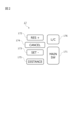
- FIG. 1 is a block diagram showing a driving support system including a driving support device of the present invention
- FIG. 2 is a front view showing part of the input device of FIG. 1
- FIG. FIG. 4 is a plan view showing lane change by autonomous lane change control
- FIG. 10 is a plan view showing a lane change to an adjacent lane by overtaking support control
- FIG. 4 is a plan view showing a lane change to the original driving lane by autonomous lane change control
- FIG. 4 is a plan view showing a lane change by route driving support control
- 2 is a block diagram showing state transitions of the driving support device of FIG. 1
- FIG. FIG. 2 is a flowchart showing an example of an information processing procedure in the driving support system of FIG. 1
- FIG. FIG. 2 is a plan view showing an example of a driving scene in which autonomous driving control is performed using the driving support system shown in FIG. 1
- FIG. 9 is a flow chart showing an example of a subroutine of step S20 of FIG
- FIG. 1 is a block diagram showing a driving support system 1 according to the invention.
- the driving support system 1 of the present embodiment is an in-vehicle system, and in addition to a private vehicle that travels by autonomous driving control to a destination set by the occupant of the own vehicle (hereinafter also simply referred to as "vehicle"), for example, a vehicle dispatch system It can also be used for vehicles dispatched in services.
- Dispatch service refers to assigning and dispatching vehicles that transport users from pick-up points to drop-off points. and dispatch of vehicles used for rental car and ride-sharing services. Users of the dispatch service are not particularly limited as long as they can appropriately pay for the service.
- the driving support system 1 includes an imaging device 11, a distance measuring device 12, map information 13, a vehicle position detecting device 14, a navigation device 15, a vehicle control device 16, an input device 17, an output device 18 and A driving support device 19 is provided.
- Devices included in the driving support system 1 are connected by a CAN (Controller Area Network) or other in-vehicle LAN, and can exchange information with each other.
- CAN Controller Area Network
- the imaging device 11 is a device that recognizes objects around the own vehicle from images, and is, for example, a camera equipped with an imaging device such as a CCD, an ultrasonic camera, an infrared camera, or the like.
- a plurality of imaging devices 11 can be provided in one vehicle. For example, they can be arranged in the front grille, under the left and right door mirrors, and in the vicinity of the rear bumper of the vehicle. This can reduce blind spots when recognizing objects around the vehicle.
- the imaging device 11 also includes a driver monitor that captures an image of the driver.
- Range finder 12 is a device for calculating the relative distance and relative speed between the vehicle and the object.
- Radar equipment such as sonic radar, or sonar.
- a plurality of distance measuring devices 12 can be provided in one vehicle, and can be arranged, for example, in the front, right side, left side, and rear of the vehicle. Accordingly, it is possible to accurately calculate the relative distance and relative speed of the vehicle to surrounding objects.
- Objects detected by the imaging device 11 and the distance measuring device 12 include road lane boundaries, center lines, road markings, median strips, guardrails, curbs, side walls of highways, road markings, traffic lights, pedestrian crossings, and construction work. Sites, accident sites, traffic restrictions, and the like. Objects also include obstacles that may affect the travel of the own vehicle, such as automobiles other than the own vehicle (other vehicles), motorcycles, bicycles, and pedestrians.
- the detection results of the imaging device 11 and the distance measuring device 12 are acquired by the driving support device 19 at predetermined time intervals.
- the detection results of the imaging device 11 and the distance measuring device 12 can be integrated or synthesized by the driving support device 19, thereby complementing missing information of the detected object.
- the driving support device 19 It can calculate the position information of objects.
- the calculated object position information is integrated with the detection results of the imaging device 11 and the distance measuring device 12 and a plurality of information such as the map information 13 in the driving support device 19, and is combined with the environment information around the own vehicle. Become. It is also possible to recognize objects around the own vehicle by using the detection results of the imaging device 11 and the distance measuring device 12 and the map information 13, and predict the movements of the objects.
- the map information 13 is information used for generating a travel route and/or for travel control, and includes road information, facility information, and attribute information thereof.
- Road information and road attribute information include road width, road curvature and radius of curvature, road shoulder structures, road traffic regulations (speed limit, lane change availability), road junctions and junctions, number of lanes, etc. Information such as increase/decrease position is included.
- the map information 13 of the present embodiment is high-precision map information that can grasp the movement trajectory of each lane. information, road attribute information, lane up/down information, lane identification information, connection destination lane information, and the like.
- a high-definition map is also called an HD (High-Definition) map.
- the road/lane boundary information in the high-precision map information is information that indicates the boundary between the road on which the vehicle is traveling and other areas.
- the road on which the vehicle travels is a road on which the vehicle travels, and the shape of the road is not particularly limited.
- the boundaries exist on the left and right with respect to the traveling direction of the host vehicle, and the form is not particularly limited. Boundaries include road markings, road structures, etc. Road markings include lane boundaries, center lines, etc. Road structures include medians, guardrails, curbs, tunnels, highway sidewalls, etc. be At a point such as an intersection where the road boundary cannot be clearly specified, the road boundary is set in advance. This boundary is fictitious and not an actual roadway marking or roadway structure.
- the map information 13 is stored in a readable state in a recording medium of an in-vehicle device including the driving support device 19 or a server on the network.
- the driving support device 19 acquires the map information 13 as necessary.
- the own vehicle position detection device 14 is a positioning system for detecting the current position of the own vehicle, and is not particularly limited, and a known system can be used.
- the vehicle position detection device 14 calculates the current position of the vehicle from radio waves received from GPS (Global Positioning System) satellites, for example.
- GPS Global Positioning System
- the vehicle position detection device 14 estimates the current position of the vehicle from the vehicle speed information obtained from the vehicle speed sensor and the acceleration information obtained from the acceleration sensor and the gyro sensor, and compares the estimated current position with the map information 13.
- the current position of the own vehicle may be calculated by
- the navigation device 15 is a device that refers to the map information 13 to calculate the travel route from the current position of the vehicle detected by the vehicle position detection device 14 to the destination set by the driver.
- the navigation device 15 uses, for example, the road information and facility information of the map information 13 to search for a travel route for the vehicle to reach the destination from the current position.
- the travel route includes at least information about the road on which the vehicle travels, the travel lane, and the travel direction of the vehicle, and is displayed linearly, for example. A plurality of travel routes may exist depending on the search conditions.
- the travel route calculated by the navigation device 15 is output to the travel support device 19 .
- the vehicle control device 16 is an in-vehicle computer such as an electronic control unit (ECU), and electronically controls in-vehicle equipment that governs the running of the vehicle.
- the vehicle control device 16 includes a vehicle speed control device 161 that controls the running speed of the vehicle and a steering control device 162 that controls the steering operation of the vehicle.
- the vehicle speed control device 161 and the steering control device 162 autonomously control the operations of these driving device and steering device according to control signals input from the driving support device 19 .
- the own vehicle can autonomously travel along the set travel route.
- the drive devices controlled by the vehicle speed control device 161 include an electric motor and/or an internal combustion engine as a travel drive source, a power transmission device including a drive shaft and an automatic transmission that transmit the output from these travel drive sources to the drive wheels, A driving device for controlling a power transmission device and the like are included.
- a braking device controlled by vehicle speed control device 161 is, for example, a braking device for braking wheels.
- a control signal corresponding to the set running speed is input to the vehicle speed control device 161 from the driving support device 19 .
- the vehicle speed control device 161 generates a signal for controlling these drive devices based on the control signal input from the driving support device 19, and transmits the signal to the drive device to autonomously control the traveling speed of the vehicle. to control.
- the steering device controlled by the steering control device 162 includes a steering device that controls all the steering wheels according to the steering angle of the steering wheel (so-called steering wheel), for example, a steering actuator such as a motor attached to the steering column shaft.
- a steering wheel for example, a steering actuator such as a motor attached to the steering column shaft.
- the steering control device 162 uses the detection result of the imaging device 11 and the distance measuring device 12, the map information 13, and the current position information acquired by the vehicle position detection device 14. using at least one of, the operation of the steering system is autonomously controlled so that the vehicle travels while maintaining a predetermined lateral position (position in the lateral direction of the vehicle) with respect to the set travel route.
- the in-vehicle sensor 163 is a sensor for detecting the running state of the vehicle, and includes a vehicle speed sensor, an acceleration sensor, a gyro sensor, a steering angle sensor, an inertial measurement unit (IMU), and the like.
- the in-vehicle sensor 163 also includes a touch sensor (capacitance sensor) that detects holding of the steering wheel by the driver.
- the vehicle control device 16 outputs the detection result of the vehicle-mounted sensor 163 to the driving support device 19 at predetermined time intervals.
- the input device 17 is a device for a vehicle occupant to input instructions to the driving support device 19.
- the input device 17 includes a touch panel input by a user's finger touch or a stylus pen, a microphone for acquiring a user's voice instruction, a vehicle For example, a switch attached to the steering wheel.
- FIG. 2 is a front view showing part of the input device 17, showing a group of button switches arranged on the spokes of the handle.
- the input device 17 shown in FIG. 2 is a button switch used for setting ON/OFF of the autonomous driving control function (autonomous speed control function and autonomous steering control function) provided in the driving support device 19 .
- the input device 17 includes a main switch 171 , a resume/accelerate switch 172 , a set/coast switch 173 , a cancel switch 174 , a distance adjustment switch 175 and a lane change support switch 176 .
- the main switch 171 is a switch that turns ON/OFF the power of the system that realizes the autonomous speed control function and the autonomous steering control function of the driving support device 19 .
- the resume/accelerate switch 172 resumes the autonomous speed control at the set speed before it was turned off, increases the set speed, follows the preceding vehicle and stops, and then travels. It is a switch for restarting by the support device 19 .
- the set/coast switch 173 is a switch that starts autonomous speed control at the running speed or lowers the set speed.
- the cancel switch 174 is a switch for turning off the autonomous speed control.
- the inter-vehicle distance adjustment switch 175 is a switch for setting the inter-vehicle distance to the preceding vehicle, and is a switch for selecting one from a plurality of settings such as short distance, medium distance and long distance.
- the lane change support switch 176 is a switch for instructing (approving) the start of lane change when the driving support device 19 confirms the start of the lane change with the driver. By operating the lane change support switch 176 longer than a predetermined time after accepting the start of the lane change, the approval of the lane change proposal by the driving support device 19 can be cancelled.
- the driving support device 19 suggests whether or not to automatically change lanes, if the driver operates the direction indicator lever, the driver will head in the direction in which the direction indicator lever was operated instead of the proposed lane change. to change lanes.
- the input device 17 outputs the input setting information to the driving support device 19 .
- the details of autonomous travel control, autonomous speed control, and autonomous steering control will be described later.
- the output device 18 is a device for providing necessary information to the occupants of the vehicle. It is a display built into the mirror.
- the output device 18 is not only a device that provides information visually, but also a device that provides information by voice, such as a speaker of an audio device, and a seat that provides information by vibration, such as a seat in which a vibrating body is embedded. It also includes devices.
- the driving support device 19 controls the driving of the own vehicle by controlling and cooperating with the devices included in the driving support system 1, and directs the own vehicle to the destination set by the occupant of the vehicle or the user of the dispatch service. It is a device that runs up to
- the driving support device 19 is, for example, a computer, and includes a CPU (Central Processing Unit) 191 that is a processor, a ROM (Read Only Memory) 192 that stores a program, and a RAM (Random Access Memory) that functions as an accessible storage device. ) 193.
- the CPU 191 is an operating circuit for functioning as the driving support device 19 by executing programs stored in the ROM 192 .
- the program stored in the ROM 192 includes a control unit 2 which is a functional block for realizing control of running of the own vehicle by the running support device 19 .
- the control unit 2 has a function of causing the own vehicle to travel by autonomous travel control.
- Autonomous driving control refers to autonomously controlling the driving operation of the own vehicle using the driving support device 19, and the driving operation includes acceleration, deceleration, starting, stopping, and turning to the right or left. It includes all driving actions such as rudder, lane change, and pull-over.
- autonomously controlling the running motion means that the running support device 19 controls the running motion using the device of the host vehicle. In other words, the control unit 2 intervenes and controls these running actions within a predetermined range. The uninterrupted driving behavior is controlled manually by the driver.
- the control unit 2 includes an acquisition unit 3, a support unit 4, a determination unit 5, and a notification unit 6, as shown in FIG.
- the support unit 4 includes a speed control unit 41 and a steering control unit 42
- the steering control unit 42 includes a lane keeping unit 421 , a lane changing unit 422 , an overtaking unit 423 and a route running unit 424 .
- FIG. 1 each part is extracted and shown for convenience. Functions performed by each functional block of the control unit 2 will be described below.
- the acquisition unit 3 has a function of acquiring information about the running state of the own vehicle (hereinafter also referred to as "running information").
- the function of acquiring travel information is also referred to as "travel information acquisition function".
- the driving support device 19 uses the driving information obtaining function of the obtaining unit 3 to obtain images of the exterior of the vehicle captured by the front camera, the rear camera, and the side cameras, which are the imaging device 11, as driving information. Further, the driving support device 19 acquires the detection results of the front radar, the rear radar, and the side radar, which are the distance measuring device 12, as driving information by the driving information acquisition function of the acquisition unit 3.
- the driving support device 19 may also use the traveling speed of the own vehicle detected by the vehicle speed sensor, which is the in-vehicle sensor 163, and the image information of the driver's face captured by the in-vehicle camera as traveling information. get.
- the travel support device 19 uses the travel information acquisition function of the acquisition unit 3 to acquire the current position information of the vehicle from the own vehicle position detection device 14 as travel information.
- the travel support device 19 also acquires the set destination and the travel route to the destination from the navigation device 15 as travel information by the travel information acquisition function of the acquisition unit 3 .
- the driving support device 19 may provide location information such as a curved road and its curve size (e.g., curvature or radius of curvature), merging points, branch points, toll booths, lane reduction positions, and the like. is acquired from the map information 13 as travel information.
- the driving support device 19 acquires the information of the operation input by the driver from the input device 17 as driving information.
- the support unit 4 has a function to autonomously control the running of the own vehicle without depending on the driver's operation.
- the support unit 4 includes a speed control unit 41 having a function of autonomously controlling the traveling speed of the own vehicle, and a steering control unit 42 having a function of autonomously controlling the steering of the own vehicle.
- autonomous control of the running of the own vehicle without depending on the driver's operation is also called “autonomous running control”.
- Autonomous control of the running speed of the own vehicle is also called “autonomous speed control”
- autonomous control of the steering of the own vehicle is also called “autonomous steering control”.
- the driving support device 19 performs autonomous speed control of the speed control unit 41 so that the vehicle speed set by the driver is set as the upper limit and the distance between the vehicles is maintained according to the vehicle speed. while following the preceding vehicle.
- the vehicle travels at a constant speed set by the driver.
- the former is called inter-vehicle control, and the latter is called constant speed control.
- the speed control unit 41 uses the imaging device 11 to detect the speed limit of the road on which the vehicle is traveling from the road signs, or obtains the speed limit from the map information 13, and automatically sets the speed limit to the vehicle speed. It may have a function to make
- the driver In order to activate the autonomous speed control by the speed control unit 41, the driver first operates the resume/accelerate switch 172 or the set/coast switch 173 of the input device 17 shown in FIG. 2 to input a desired running speed. . For example, if the set coast switch 173 is pressed while the vehicle is traveling at 70 km/h, the current traveling speed is set as is. The set speed can be increased by pressing the switch 172 multiple times. Conversely, if the speed desired by the driver is 60 km/h, the set coast switch 173 should be pressed a plurality of times to lower the set speed. Further, the distance between the vehicles desired by the driver can be selected by operating the distance adjustment switch 175 of the input device 17 shown in FIG.
- Constant speed control is executed when it is detected by the forward radar of the rangefinder 12 that there is no preceding vehicle ahead of the own lane.
- the vehicle speed control device 161 controls the operation of drive mechanisms such as the engine and brakes while feeding back the vehicle speed data from the vehicle speed sensor, which is the vehicle sensor 163, so as to maintain the set running speed.
- the inter-vehicle distance control is executed when the presence of a preceding vehicle in front of the own lane is detected by the forward radar of the distance measuring device 12 or the like.
- the driving mechanism such as the engine and the brakes is controlled by the vehicle speed control device 161 while feeding back the inter-vehicle distance data detected by the front radar so as to maintain the set inter-vehicle distance with the set running speed as the upper limit. controls the behavior of Note that when the preceding vehicle stops while traveling under inter-vehicle distance control, the host vehicle also stops following the preceding vehicle.
- the own vehicle when the preceding vehicle starts moving within, for example, 30 seconds after the own vehicle stops, the own vehicle also starts and starts the follow-up running by the vehicle-to-vehicle distance control again. If the own vehicle has been stopped for more than 30 seconds, it will not automatically start even if the preceding vehicle starts moving. , the follow-up running is started again by the vehicle-to-vehicle distance control.
- the autonomous steering control by the steering control unit 42 executes the steering control of the own vehicle by controlling the operation of the steering actuator with the steering control device 162 when a predetermined condition is satisfied during execution of the above-described autonomous speed control. do.
- the steering control unit 42 includes, for example, a lane keeping unit 421, a lane changing unit 422, an overtaking unit 423, and a route running unit 424.
- the lane keeping unit 421 has a function of controlling the steering actuator with the steering control device 162 to assist the driver's steering operation so that the vehicle runs near the center of the lane.
- the function of the lane keeping unit 421 is also called a “lane keeping function” or a “lane width direction maintaining function”.
- the control by the lane keeping unit is also called “lane keeping control”.
- the lane change unit 422 has a function of changing lanes by autonomous driving control.
- autonomous driving by autonomous driving control, the control of changing the lane from the own lane in which the own vehicle is traveling to the adjacent lane adjacent to the own lane is also referred to as "autonomous lane change control”.
- the driving support device 19 turns on the direction indicator by the autonomous lane change control of the lane change unit 422, and satisfies the preset lane change start condition.
- a lane change operation hereafter, LCP
- LCP a series of lane change processes by autonomous driving control
- the driving support device 19 determines whether or not the lane change start condition is satisfied based on various types of driving information acquired by the driving information acquisition function of the acquisition unit 3 by autonomous lane change control.
- the lane change start condition is not particularly limited, but can be exemplified by satisfying all of the following conditions. ⁇ Lane keeping mode in hands-on mode. ⁇ Hands-on judgment is in progress. ⁇ The vehicle is traveling at a speed of 60 km/h or more. ⁇ There is a lane in the lane change direction. ⁇ There is a space in the lane to change lanes. - The type of lane marker can change lanes. ⁇ The radius of curvature of the road is 250m or more. ⁇ It is within 1 second after the driver operates the direction indicator lever.
- the lane keep mode of the hands-on mode means that the autonomous speed control by the speed control unit 41 and the lane keep control by the lane keep unit 421 are being executed, and the holding of the steering wheel by the driver is detected. Say what is happening.
- “during hands-on determination” means a state in which the driver continues to hold the steering wheel.
- the driving support device 19 starts LCP by the autonomous lane change control of the lane change unit 422 when the lane change start condition is satisfied.
- This LCP includes a lateral movement of the host vehicle to the adjacent lane and a lane change maneuver (hereinafter, LCM) in which the vehicle actually moves to the adjacent lane.
- LCM lane change maneuver
- the driving support device 19 uses the output device 18 to present to the driver information indicating that the vehicle is automatically changing lanes, and calls attention to the surroundings.
- the driving support device 19 turns off the direction indicator and starts control by the lane keeping unit 421 in the adjacent lane.
- the overtaking unit 423 has a function of overtaking the preceding vehicle by autonomous driving control.
- control for overtaking a preceding vehicle in autonomous driving by autonomous driving control is also referred to as "overtaking support control”.
- Passing support control is a type of autonomous lane change control, and is autonomous lane change control in a driving scene in which a vehicle passes a preceding vehicle.
- the driving support device 19 operates the overtaking unit 423 when a preceding vehicle slower than the own vehicle exists in the front of the own lane and when a predetermined overtaking proposal condition is satisfied.
- the function presents the passing information to the driver via the output device 18 .
- the overtaking information is information for proposing to the driver to overtake the preceding vehicle.
- the driving support device 19 allows the driver to operate the lane change support switch 176 of the input device 17 to approve the presentation of the overtaking information (equivalent to approval input), and also satisfies the preset overtaking start condition. If so, it initiates the LCP described above.
- the consent input includes the driver operating the turn signal lever to the right or left.
- the driving support device 19 determines whether or not the overtaking proposal condition and the overtaking start condition are satisfied based on various types of driving information acquired by the acquisition unit 3 .
- the overtaking support control may include a function of starting LCP for overtaking the preceding vehicle when the driver operates the direction indicator lever even when overtaking information is not presented.
- the overtaking proposal condition is not particularly limited, but can be exemplified by satisfying all of the following conditions.
- ⁇ Lane keeping mode in hands-off mode ⁇ The vehicle is traveling at a speed of 60 km/h or more. ⁇ There is a lane in the lane change direction. ⁇ There is a space in the lane to change lanes in 5 seconds. - The type of lane marker can change lanes. ⁇ The radius of curvature of the road is 250m or more. ⁇ The speed of the own vehicle is slower than the set speed by 5 km/h or more. ⁇ The speed of the preceding vehicle is slower than the set speed by 10 km/h or more.
- the inter-vehicle distance between the host vehicle and the preceding vehicle is below a preset threshold based on the speed difference between the host vehicle and the preceding vehicle.
- the speed of the preceding vehicle in the lane to be changed satisfies a predetermined condition.
- the lane keep mode of the hands-off mode means that the autonomous speed control of the speed control unit 41 and the lane keep control of the lane keep unit 421 are being executed, and the driver is not holding the steering wheel. Say unnecessary mode.
- the condition that the speed of the preceding vehicle in the lane to be changed satisfies the predetermined condition is applied differently depending on the type of lane to be changed. For example, when changing lanes from the left lane to the right lane on a road with multiple lanes of left-hand traffic, the speed of the vehicle in the left lane is about 5 km/h faster than the speed of the preceding vehicle in the right lane. Faster than this is a condition.
- the overtaking start condition is not particularly limited, but can be exemplified by satisfying all of the following conditions. ⁇ Lane keeping mode in hands-on mode. ⁇ Hands-on judgment is in progress. ⁇ The vehicle is traveling at a speed of 60 km/h or more. ⁇ There is a lane in the lane change direction. ⁇ There is a space in the lane to change lanes. - The type of lane marker can change lanes. ⁇ The radius of curvature of the road is 250m or more.
- the speed of the own vehicle is slower than the set speed by 5 km/h or more (when changing lanes to the right lane while driving on the left side).
- the speed of the preceding vehicle is slower than the set speed by 10 km/h or more (when changing lanes to the right lane while driving on the left side).
- the speed of the preceding vehicle in the lane to be changed satisfies a predetermined condition. - Within 10 seconds from the operation of the lane change support switch 176;
- the condition that the speed of the preceding vehicle is 10 km/h or more slower than the set speed can be changed by the driver's settings, and the set speed after the change becomes the overtaking start condition.
- a changeable speed for example, 15 km/h and 20 km/h can be selected in addition to 10 km/h.
- the condition that the speed of the preceding vehicle in the lane to be changed satisfies the predetermined condition is the same as the overtaking proposal condition described above.
- the driving support device 19 starts LCP by overtaking support control, laterally moves to the adjacent lane, and executes LCM.
- the driving support device 19 uses the output device 18 to present to the driver information indicating that the vehicle is automatically changing lanes while the LCP is being executed by the overtaking support control, and calls attention to the surroundings.
- the driving support device 19 turns off the direction indicator and starts lane keeping control of the lane keeping unit 421 in the adjacent lane.
- the passing unit 423 also has a function of suggesting to the driver to return to the original lane by the output device 18 when the overtaking proposal condition is satisfied again after overtaking the preceding vehicle.
- the driving support device 19 When the driver accepts this proposal by operating the lane change support switch 176 of the input device 17 and the overtaking start condition is satisfied, the driving support device 19 performs overtaking support as shown in FIG. LCP is started so that the own vehicle is returned to the original lane by control.
- the route running unit 424 has a function of running the own vehicle along the set running route.
- the route travel unit 424 causes the own vehicle to travel along the set travel route by route travel support control.
- route driving support control is a type of autonomous lane change control, and is autonomous lane change control in a driving scene in which the own vehicle travels along a set driving route.
- the travel support device 19 is configured such that the set travel route includes a travel direction change point such as a branch point, a merging point, an exit, a tollgate, etc., the distance to the travel direction change point is within a predetermined distance, and a predetermined distance is reached.
- the route travel information is presented by the output device 18 by the function of the route travel section 424, and a lane change to the travel direction change point is proposed. Further, the driving support device 19 starts the LCP when the lane change proposal is accepted by the operation of the lane change support switch 176 and a predetermined route driving start condition is satisfied.
- the operation of the lane change support switch 176 may be the operation of the direction indicator lever by the driver.
- the travel support device 19 determines whether or not the route travel proposal condition and the route travel start condition are satisfied based on various travel information acquired by the travel information acquisition function of the acquisition unit 3 .
- route driving support control is a function that initiates LCP for driving along the driving route when the driver operates the direction indicator lever even if the route driving information does not suggest a lane change.
- the vehicle makes two lane changes in sequence toward a branch point that exists in the left lane. It shows an example of moving to a fork road (also called a fork road, the same applies hereinafter) extending to the left side of the lane.
- a fork road also called a fork road, the same applies hereinafter
- the route travel unit 424 Route driving support control proposes a lane change from the right lane to the center lane based on the route driving information.
- the first predetermined distance (also referred to as a proposed lane change section) is set in advance according to the number of lane changes required to move to the lane where the travel direction change point exists. For example, as shown in FIG. 6, when it is necessary to change lanes twice from the right lane to the left lane via the center lane, as shown in the example, the distance between about 2.5 km and 1.0 km before the branch point is reached. The section becomes the first predetermined distance (lane change proposed section).
- working proposal conditions the following conditions are all satisfied, etc. can be illustrated.
- the destination is set in the navigation device 15 .
- the vehicle is traveling at a speed of 60 km/h or more.
- the type of lane marker can change lanes.
- the radius of curvature of the road is 250m or more.
- route proposal conditions route information is presented to notify the driver that it is necessary to change lanes along the driving route even if there is no space to change lanes.
- the driving support device 19 turns on the direction indicator by the route driving support control of the route driving unit 424 when the driver consents to the lane change for heading to the branch point and the route driving start condition is satisfied.
- Start LCP The condition for starting route travel is not particularly limited, but can be exemplified by satisfying all of the following conditions. ⁇ Lane keeping mode in hands-on mode. ⁇ Hands-on judgment is in progress. ⁇ The vehicle is traveling at a speed of 60 km/h or more. ⁇ There is a lane in the lane change direction. ⁇ There is a space in the lane to change lanes. - The type of lane marker can change lanes. ⁇ You are driving in the proposed lane change section. ⁇ The radius of curvature of the road is 250m or more.
- the travel support device 19 starts LCP by route travel support control of the route travel unit 424, and executes lateral movement to the center lane and LCM.
- the driving support device 19 turns off the direction indicator and starts lane keeping control of the lane keeping unit 421 in the center lane.
- the driving support device 19 presents to the driver, through the output device 18, information indicating that the vehicle is automatically changing lanes while the LCP is being executed by means of the route driving support control, and calls attention to the surroundings.
- the driving support device 19 during execution of the lane keep control in the center lane, is within a second predetermined distance to the branch point (for example, about 2.3 km to 700 m before the branch point). If there is and the route running start condition is satisfied, the turn signal is turned on by the route running support control, the second LCP is started, and the lane is changed from the center lane to the left lane. When the second LCM is completed, the driving support device 19 turns off the direction indicator and starts lane keeping control of the lane keeping unit 421 in the left lane.
- the driving support device 19 is within a third predetermined distance to the branch point (for example, about 800 m to 150 m before the branch point) during execution of lane keep control in the left lane, and the route travel start condition is When the condition is satisfied, the direction indicator is turned on by the route driving support control.
- the driving support device 19 starts steering control from the point beyond the branch point to the branch road by the route driving support control of the route driving unit 424, and performs the lane change from the left lane to the branch road by the autonomous driving control.
- the above-described autonomous steering control is used for the steering control.
- the driving support device 19 turns off the direction indicator and starts the lane keep control of the lane keep unit 421 at the fork road.
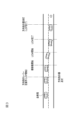
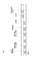
- FIG. 7 is a block diagram showing state transitions of each function established in the driving support device 19.
- the system shown in FIG. 7 means an autonomous driving control system realized by the driving support device 19 .
- the main switch 171 shown in FIG. 2 is turned ON from the system OFF state shown in FIG. 7, the system enters the standby state. From this standby state, by turning on the set/coast switch 173 or the resume/accelerate switch 172 in FIG. 2, the autonomous speed control by the autonomous speed control function is activated.
- the above-described constant speed control or inter-vehicle distance control is started, and the driver can drive the own vehicle simply by operating the steering wheel without stepping on the accelerator or brake.
- condition (1) in FIG. 7 is established while the autonomous speed control is being executed, the lane keeping mode of the autonomous steering control/hands-on mode is entered.
- This condition (1) is not particularly limited, but can be exemplified by satisfying all of the following conditions. ⁇ Lane markers on both sides of the vehicle are detected. ⁇ The driver is holding the steering wheel. ⁇ You are driving near the center of the lane. ⁇ The direction indicator is not working. ⁇ The wipers are not operating at high speed (HI). ⁇ If there is a high-definition map, there are no toll gates, exits, junctions, intersections, or lane reduction points within about 200m ahead.
- Hands-on mode is a mode in which autonomous steering control by the autonomous steering control function does not operate unless the driver is holding the steering wheel. This is the mode in which the autonomous steering control by function operates.
- the touch sensor of the in-vehicle sensor 163 detects the driver's holding of the steering wheel.
- condition (2) in FIG. 7 If the condition (2) in FIG. 7 is satisfied while the lane keeping mode of the autonomous steering control/hands-on mode is being executed, the lane keeping mode of the autonomous steering control/hands-off mode is entered.
- This condition (2) can be exemplified by the fact that all of the following conditions are satisfied. - The vehicle is traveling on a motorway. ⁇ You are driving on a road that is structurally separated from oncoming traffic. ⁇ You are driving on a road with a high-definition map. ⁇ The vehicle is traveling at a speed below the speed limit. • GPS signal is valid. ⁇ The driver is holding the steering wheel. ⁇ The driver is facing forward.
- the condition (3) is not particularly limited, but can be exemplified by satisfying any of the following conditions. ⁇ The own vehicle is traveling on a road other than an expressway. ⁇ You are driving in a two-way section. ⁇ You are driving on a road without a high-definition map. ⁇ The vehicle is traveling at a speed exceeding the speed limit. ⁇ GPS signals cannot be received. ⁇ The driver did not turn forward within 5 seconds after the forward gaze warning was activated. ⁇ The driver monitor camera can no longer detect the driver.
- condition (4) in FIG. 7 is satisfied while the lane keeping mode of the autonomous steering control/hands-off mode is being executed, the autonomous steering control is stopped and the transition is made to the autonomous speed control.
- the condition (4) is not particularly limited, but can be exemplified by satisfying any of the following conditions. ⁇ Lane markers on both sides of the vehicle are no longer detected for a certain period of time. ⁇ The driver is operating the steering wheel. ⁇ The wipers are operating at high speed (HI). The steering wheel operation by the driver is determined by detecting the torque applied to the steering wheel by the in-vehicle sensor 163 .
- the condition (5) in FIG. 7 is satisfied while the lane keeping mode of the autonomous steering control/hands-off mode is being executed, the autonomous steering control and the autonomous speed control are stopped and the state is changed to the standby state.
- the condition (5) is not particularly limited, but can be exemplified by satisfying any of the following conditions. ⁇ The driver operated the brake. - The driver operates the cancel switch 174 in FIG. ⁇ The door of the vehicle is opened. - The driver's seat belt has been released. ⁇ The seat sensor detects that the driver has left the driver's seat. ⁇ The selector lever is in a position other than "D" or "M.” ⁇ The parking brake is activated. ⁇ The anti-skid system of the vehicle has been turned off.
- the skid prevention device has been activated. ⁇ Snow mode is turned on. ⁇ The emergency brake has been activated. ⁇ After the vehicle was stopped by the vehicle speed control, the stopped state continued for about 3 minutes. ⁇ The front camera detects poor visibility, such as the inability to correctly recognize objects due to dirt, backlight, rain, or fog. ⁇ The forward radar detected shielding and radio interference. ⁇ The forward radar detected an axis misalignment. ⁇ Side radar detected shielding and radio interference. ⁇ The side radar detected an axis misalignment.
- Condition (6) is not particularly limited, but can be exemplified by satisfying any of the following conditions. ⁇ Lane markers on both sides of the vehicle are no longer detected. ⁇ The driver operated the steering wheel. ⁇ The driver operated the direction indicator lever. ⁇ The wiper operated at high speed (HI). ⁇ When there is a high-precision map, it became a tollgate section. ⁇ The front camera detects poor visibility, such as dirt, backlight, rain, or fog, which prevents the vehicle from correctly recognizing objects.
- condition (7) in FIG. 7 is satisfied while the autonomous steering control/hands-on mode is being executed, the autonomous steering control and the autonomous speed control are stopped and the state is changed to the standby state.
- This condition (7) is not particularly limited, but can be exemplified by satisfying any of the following conditions. ⁇ The driver operated the brake. - The driver operates the cancel switch 174 in FIG. ⁇ The door of the vehicle is opened. - The driver's seat belt has been released. ⁇ The seat sensor detects that the driver has left the driver's seat. ⁇ The selector lever is in a position other than "D" or "M.” ⁇ The parking brake is activated. ⁇ The anti-skid system of the vehicle has been turned off.
- the anti-skid system has been activated. ⁇ Snow mode is turned on. ⁇ The emergency brake has been activated. ⁇ After the vehicle was stopped by the vehicle speed control, the stopped state continued for about 3 minutes. ⁇ The forward radar detected shielding and radio interference. ⁇ The forward radar detected an axis misalignment.
- Condition (8) is not particularly limited, but can be exemplified by satisfying any of the following conditions.
- ⁇ The parking brake is activated.
- the anti-skid system of the vehicle has been turned off.
- ⁇ The anti-skid system has been activated.
- ⁇ Snow mode is turned on.
- ⁇ The emergency brake has been activated. ⁇ After the vehicle was stopped by the vehicle speed control, the stopped state continued for about 3 minutes. ⁇ The forward radar detected shielding and radio interference. ⁇ The forward radar detected an axis misalignment.
- condition (9) in FIG. 7 If the condition (9) in FIG. 7 is satisfied while the lane keep mode of the autonomous steering control/hands-off mode is being executed, the lane change mode of the autonomous steering control/hands-on mode is entered.
- This condition (9) is not particularly limited, but can be exemplified by satisfying any of the following conditions. - The system proposed a lane change based on the passing support control of the passing section 423 or the route driving support control of the route driving section 424, and the driver operated the lane change support switch 176. ⁇ The driver operated the direction indicator lever to perform autonomous lane change control.
- the lane change mode of the autonomous steering control/hands-on mode is entered.
- the condition (10) is not particularly limited, but can be exemplified by satisfying any of the following conditions. • The speed limit was exceeded before the start of the LCP. ⁇ The driver held the steering wheel and stepped on the accelerator pedal before the LCP started. - LCP could not start within 10 seconds after pushing the lane change assist switch 176 during a lane change proposal when there is a slow car ahead. - After pressing the lane change support switch 176 during the lane change proposal for traveling along the travel route, the LCP could not be started and the vehicle was too close to the branch point.
- the LCM could not be started within 5 seconds after the activation of the LCP. ⁇ The vehicle speed dropped below approximately 50 km/h before the LCP was started and the LCM was started. - After the LCP has activated, there is no more adjoining lane space to change lanes before the LCM starts. ⁇ The driver performed a cancel operation before the LCM started. ⁇ The lane marker became non-detected before the start of LCM. ⁇ Before the start of the LCM, it was determined that there was no adjacent lane in the direction of the lane change, or that there would be no adjacent lane within a certain distance ahead.
- the hands-on alarm is activated when any of the following conditions are met. ⁇ The driver did not hold the steering wheel within about two seconds after the LCP was activated. - The driver did not hold the steering wheel within about 2 seconds after pressing the lane change assistance switch 176 during the lane change proposal when there was a slow car ahead. - The driver did not hold the steering wheel within about 2 seconds after pressing the lane change assistance switch 176 during the lane change proposal for traveling according to the travel route.
- the main switch 171 When the main switch 171 is turned off in any of the autonomous steering control/hands-off mode, autonomous steering control/hands-on mode, autonomous speed control, and standby state, the system is turned off.
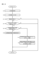
- FIG. 8 is an example of a flow chart showing travel control processing according to the present embodiment.
- the driving support device 19 executes a driving control process described below at predetermined time intervals. Further, in the following description, the driving support device 19 executes autonomous speed control using the function of the speed control unit 41 and executes autonomous steering control using the function of the steering control unit 42 . Further, the driving support device 19 executes lane change support control using the function of the lane changing unit 422, executes overtaking support control using the function of the overtaking unit 423, and executes route driving support control using the function of the route driving unit 424. shall be
- step S1 of FIG. 8 it is determined whether or not the main switch 171 of the driving support device 19 is turned on. If the main switch 171 is turned off, step S1 is repeated until it is turned on. If the main switch 171 is ON, the process proceeds to step S2 to determine whether or not the driver has set the running speed. If the travel speed has not been set, the process returns to step S1, and steps S1 and S2 are repeated until the travel speed is set.
- the driving speed is set by the driver by operating the resume/accelerate switch 172 or the set/coast switch 173 of the input device 17 shown in FIG. 2 to input a desired driving speed.
- Autonomous speed control starts when the running speed is set.
- the front radar which is the distance measuring device 12, is used to detect whether or not there is a preceding vehicle ahead of the lane in which the vehicle is traveling. Execute control. If there is no preceding vehicle, the routine proceeds to step S5 to execute constant speed control. As a result, the driver can drive the vehicle at a desired speed simply by operating the steering wheel without stepping on the accelerator or brake.
- step S6 While the vehicle distance control in step S4 or the constant speed control in step S5 is being executed, in step S6, whether or not the condition (1) for transitioning to the autonomous steering control/hands-on mode lane keep mode is established. judge. If the condition (1) is satisfied, the process proceeds to step S7, and if the condition (1) is not satisfied, the process returns to step S3.
- step S7 the forward radar (ranging device 12) that detects obstacles in front of the vehicle is used to detect whether or not there is a preceding vehicle ahead of the lane in which the vehicle is traveling. If there is a preceding vehicle, the process proceeds to step S8 to execute the inter-vehicle distance control/lane keep mode. If there is no preceding vehicle, the process proceeds to step S9 to execute the constant speed control/lane keep mode.
- step S10 While the vehicle distance control/lane keeping mode in step S8 or the constant speed control/lane keeping mode in step S9 is being executed, the condition (2) for transitioning to the above-described autonomous steering control/hands-off mode in step S10. is established. If the condition (2) is satisfied, the process proceeds to step S11, and if the condition (2) is not satisfied, the process returns to step S3.
- step S11 when the condition (2) for transitioning to the autonomous steering control/hands-off mode is established, the lane in which the vehicle is traveling is detected using a forward radar (ranging device 12) that detects obstacles in front of the vehicle. It detects whether or not there is a preceding vehicle ahead.
- a forward radar ranging device 12
- step S12 If there is a preceding vehicle, the process advances to step S12 to execute inter-vehicle distance control, lane keep mode, and hands-off. If there is no preceding vehicle, the process advances to step S13 to execute constant speed control, lane keep mode, and hands-off.
- step S14 it is determined whether or not the driver has operated the direction indicator lever.
- the condition (9) for transitioning to the lane change mode of the autonomous steering control/hands-on mode is established, and the process proceeds to step S15.
- step S15 lane change support control is executed. When the lane change support control in step S15 is completed, the process returns to step S3. If the driver does not operate the direction indicator lever in step S14, the process proceeds to step S16.
- step S16 it is determined whether or not there is a preceding vehicle whose speed is slower than the set speed. If there is a preceding vehicle slower than the set speed, it is determined whether or not condition (9) is met. Transition to step S17.
- step S17 overtaking support control is executed. When the overtaking support control in step S17 is completed, the process returns to step S3. If there is no preceding vehicle slower than the set speed in step S16, the process proceeds to step S18.
- step S18 it is determined whether a travel route to the destination is set in the navigation device 15. If the travel route is not set, the process returns to step S1.
- step S18 when the travel route to the destination is set in the navigation device 15, the process proceeds to step S19.
- step S19 it is determined whether or not the vehicle has reached a predetermined distance to a travel direction change point such as a branch point on the travel route. If it is determined in step S19 that the vehicle has reached the predetermined distance from the point where the traveling direction is to be changed, it is determined whether or not condition (9) is established. If condition (9) is established, autonomous steering control/hands-on mode lane change mode, and proceeds to step S20.
- step S20 route driving support control is executed. When the route driving support control in step S20 is completed, the process returns to step S3. If it is determined in step S19 that the predetermined distance has not been reached to the traveling direction change point, the process returns to step S1.
- the necessity of lane change support control, overtaking support control, and route driving support control is determined in order.
- the support controls arbitrate whether or not execution is necessary, and the support control to be executed preferentially is determined.
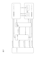
- FIG. 9 is a plan view showing an example of a driving scene in which autonomous driving control is performed using the driving support system 1.
- FIG. The running direction of the vehicle on the road shown in FIG. 9 is the direction from the lower side to the upper side of the drawing, which is indicated by arrow A in the lower right of FIG.
- the road shown in FIG. 9 has a lane L1 on the right side in the traveling direction and a lane L2 on the left side in the traveling direction. are doing.
- the own vehicle V is driving at position P1 on lane L2. It is also assumed that the destination Px set by the driver exists ahead of the lane L3 in the traveling direction, and that the navigation device 15 has set a traveling route toward the destination Px. In this case, in order to travel along the travel route, the own vehicle V needs to change lanes from lane L2 to lane L3 and enter lane L3, which is a branch line. In order to allow the vehicle V to enter the lane L3, the driving support device 19 causes the vehicle V to travel from the position P1 to the position P2 along the trajectory T1, and starts the first LCP at the position P2 on the lane L2. Then, the own vehicle V is caused to travel along the trajectory T2, and the LCP is completed at the position P3 on the lane L3.
- autonomous lane change In the driving scene shown in FIG. 9, since the angle ⁇ between the main line L2 and the branch line L3 is relatively large, the vehicle V decelerates greatly and turns left at a large steering angle in order to enter the branch line L3. There is a need. In this way, in a driving scene in which the behavior of the own vehicle V changes significantly, lane change using autonomous lane change control (hereinafter also simply referred to as "autonomous lane change”) cannot be executed. Notify the driver in advance that the autonomous lane change cannot be performed. For example, in the driving scene shown in FIG. 9, when the own vehicle V reaches the notification position X, the driver is notified that the autonomous lane change cannot be executed. The output device 18 is used for the notification. The driver, who is notified that autonomous lane change cannot be executed, understands that all autonomous lane changes cannot be executed, and tries to manually change the lane from main line L2 to branch line L3.
- the driving support device 19 notifies the driver that the autonomous lane change cannot be executed. It is only the autonomous lane change from the main line L2 to the branch line L3 by the support control. That is, even after passing the notification position X, the autonomous lane change by the autonomous lane change control of the lane change section 422 and the autonomous lane change by the overtaking support control of the overtaking section 423 can be executed. Therefore, when the driver turns the direction indicator lever to the right after passing the notification position X, the autonomous lane change from lane L2 to lane L1 is executed by the function of the lane change unit 422 .
- the functions of the determination unit 5 and the notification unit 6 are used to notify the driver that the autonomous lane change cannot be executed. After that, the executable control recognized by the driver and the actually executable control are matched to suppress the driver's discomfort caused by the discrepancy between the two. Functions of the determination unit 5 and the notification unit 6 will be described below.
- the determination unit 5 has a function of determining whether it is necessary to change the route following lane.
- a route-following lane change refers to a lane change necessary to travel along a set travel route. Whether or not it is necessary to change lanes to follow the travel route depends on the road information in the map information 13, information on the current position of the vehicle V obtained from the vehicle position detection device 14, and information from the navigation device 15. The determination is made using the acquired travel route information.
- the number of lanes of the road in the driving direction ahead of the road on which the vehicle V is running will increase. determine whether For example, when the road on which the vehicle V is traveling splits into a main line and a branch line ahead of the current position of the vehicle V, it is determined that the number of lanes on the road increases. As another example, when another lane joins the main road on which the vehicle V is traveling in front of the current position of the vehicle V, it is determined that the number of lanes on the road increases.
- the road It is determined that the number of lanes increases.
- the number of lanes on the road decreases. Then judge. If neither a branch position nor a lane merging position exists ahead of the current position of the vehicle V, it is determined that the number of lanes on the road does not change.
- the driving support device 19 determines whether to go to the set destination. , determines whether the host vehicle V needs to enter the increased lane. For example, when the road on which the vehicle V is traveling diverges into a main line and a branch line in front of the current position of the vehicle V, when a driving route for traveling on the main line is set, the vehicle V can: It is determined that there is no need to enter the increased lane. In other words, it is determined that the route following lane change is unnecessary.
- the lane of the road on which the vehicle V travels is specified, and when the vehicle V travels along the specified lane and the travel route, may be compared with the lane in which The lane in which the vehicle V is traveling is the same as the lane in which it would travel if it were to travel along the travel route, or the vehicle V would follow the travel route even if it continues to travel in the lane it is currently traveling in. If it is determined that it is possible, it is determined that the route following lane change is unnecessary.
- the vehicle V is driving at the position P1 of the lane L2, so the road on which the vehicle V is driving is a branch position B ahead of the position P1, which is the current position of the vehicle V. , it branches into a main line L2 and a branch line L3. Therefore, the number of lanes on the road will increase. Further, the travel route toward the destination Px is set so as to enter the branch line L3. Therefore, the driving support device 19 determines that the host vehicle V needs to change lanes from lane L2 to lane L3 (that is, it determines that a route following lane change is necessary).
- a travel route is set in which the vehicle travels along the main lane L1 or L2. Therefore, even if the host vehicle V continues to travel in the lane L2, it can follow the travel route, so it is determined that the route following lane change is unnecessary.
- the above-described determination of whether a route following lane change is necessary is performed within a predetermined distance from the current position of the vehicle V.
- An appropriate value can be set for the predetermined distance within a range in which the driver will not be confused as to whether the guidance of the driving support device 19 is appropriate.
- the predetermined distance is, for example, 500-1500m. If the predetermined distance is set longer than this, the traveling distance to reach the lane change position will be longer, and the driver will be confused whether the guidance of the driving support device 19 is appropriate or not, and feel uncomfortable.
- the determination unit 5 determines that it is not necessary to change the lane following the route, it instructs the support unit 4 to execute or continue the lane keep control of the lane keep unit 421 .
- the determination unit 5 determines whether or not the route following lane change can be supported by autonomous lane change control. Specifically, the driving support device 19 uses the function of the determination unit 5 to determine whether or not an execution condition for executing an autonomous lane change is satisfied.
- the execution condition under which the autonomous lane change can be executed is a condition for changing the lane without giving discomfort or discomfort to passengers including the driver. This is a condition for not changing the directional behavior significantly.
- the execution conditions are, for example, the condition (1) for transitioning to the autonomous steering control/hands-on mode and the condition (9) for switching to the lane change mode shown in FIG.
- the execution conditions include, for example, detection of lane markers on both sides of the vehicle V, the driver holding the steering wheel, the vehicle V running near the center of the lane, and the direction indicator being activated.
- wipers are not operating at high speed (HI) (that is, heavy rain or snow is not observed around the vehicle V); (In particular, the high-precision map information must be available for the road on which the vehicle V1 travels from the time the autonomous lane change is started until the autonomous lane change is completed).
- HI high speed
- the high-precision map information must be available for the road on which the vehicle V1 travels from the time the autonomous lane change is started until the autonomous lane change is completed.
- a predetermined range for example, running speed of 1 to 30 km/h or more and 40 to 70 km/h or less
- GPS signal valid the radius of curvature of the road on which the vehicle V1 travels is greater than or equal to a predetermined value (for example, 200 to 1000 m) from the start of the autonomous lane change to the completion thereof, and a sharp curve of 100R or less within about 500 m ahead.
- the driver did not drive in a tunnel beyond 500 m from the tunnel entrance; It includes the operation of a direction indicator lever for executing autonomous lane change control and the existence of a space in the adjacent lane for the own vehicle V to enter the adjacent lane.
- the execution conditions include that the behavior of the own vehicle V is within a range that can be controlled by autonomous lane change control while the autonomous lane change is being executed.
- the range that can be controlled by the autonomous lane change control is set by at least one of the acceleration, deceleration and lateral acceleration of the host vehicle V1.
- An appropriate value can be set within a range that does not give a sense of discomfort.
- the reason why the behavior of the vehicle V deviates from the range that can be controlled by the autonomous lane change control is the shape of the road on which the vehicle V travels.
- the road may be registered in advance in the high-precision map information as a road that cannot be changed.
- the execution condition includes that the distance from the current position of the host vehicle V to the position where lane change is no longer possible is longer than the travel distance (eg, 700 to 1500 m) required to execute LCP or LCM.
- the position Y is the position where the main line L2 and the branch line L3 diverge
- the distance from the current position of the vehicle V to the position where the lane cannot be changed is shown in FIG. is a distance D along the traveling direction (direction of arrow A) of the road on which the vehicle V travels.
- changing lanes before reaching the position Y means that when the vehicle V is viewed from above, before the rear end of the vehicle body of the vehicle V reaches the position Y, the entire vehicle body of the vehicle V is included in the branch line L3. That is, it is sufficient that the LCM is completed before the rear end of the vehicle body of the host vehicle V reaches the position Y, and the LCP is not necessarily completed.
- the execution condition includes, when the road on which the vehicle V is traveling after the completion of the route following lane change merges with a different road in front of the vehicle V in the traveling direction, the road is changed from the position where the route following lane change is completed.
- the distance to the merging position is less than a predetermined distance (for example, 50 to 500 m), and the speed limit of the road on which the vehicle V is entering is the same as that of the road on which the vehicle V was traveling when the route-following lane change was started. It may include being set lower than the speed limit. For example, if the main line L2 shown in FIG. 9 is a motorway and the branch line L3 joins the general road about 200 m ahead of the position P3, the execution condition is not satisfied.
- the speed limit of the general road is set lower than the speed limit of the lane L2 in which the vehicle V was traveling at the start of the lane change, and the vehicle V has a large speed limit 200m before entering the general road. This is because it is necessary to slow down.
- the execution condition includes, if an intersection exists in front of the vehicle V in the direction of travel on the road on which the vehicle V travels after the route following lane change is completed, the distance from the position where the route following lane change is completed to the intersection is as follows: It may include that the distance is less than or equal to a predetermined distance (eg, 50-500m). For example, if the main line L2 shown in FIG. 9 is a motorway and there is an intersection about 300 m ahead of the position P3 of the branch line L3, the execution condition is not satisfied. This is because, in order to enter the intersection, it is necessary to reduce the running speed to a slow speed (eg, 5 to 20 km/h), so the host vehicle V must decelerate significantly 300 m before the intersection.
- a predetermined distance eg, 50-500m
- the support unit 4 determines that the conditions for executing the autonomous lane change described above are satisfied, it determines that the route following lane change can be supported by the autonomous lane change control. Then, by the route driving support control of the route driving unit 424, an autonomous lane change is executed as a route following lane change. On the other hand, when it is determined that the conditions for executing the autonomous lane change are not satisfied, it is determined that the route following lane change cannot be supported by the autonomous lane change control. In this case, the route following lane change is performed manually by the driver. At this time, in order to prompt the driver to manually change the lane, the function of the support unit 4 notifies the driver that the autonomous lane cannot be changed. For the notification, an output device 18 such as a display in the instrument panel or a speaker is used. Note that the notification may be performed by the function of the notification unit 6 .
- the support unit 4 notifies the driver that the lane cannot be changed by the autonomous lane change control, and also uses the autonomous lane change control to change the lane in the direction opposite to the direction in which the host vehicle V is moving due to the route following lane change. forbid to support.
- the direction in which the vehicle V moves when changing lanes to follow the route is the steering direction of the vehicle V, and is the direction in which the steering wheel is rotated when changing lanes.
- the lane is changed from the main line L2 to the branch line L3, so the direction in which the vehicle V moves in the route following lane change is to the left.
- the support unit 4 does not support the lane change to the right with respect to the traveling direction by autonomous lane change control until the vehicle V passes the branch position B.
- the prohibition of changing the autonomous lane to the right may be until the LCM or LCP of the own vehicle V is completed, or until the own vehicle V reaches the position Y where the main line L2 and the branch line L3 diverge.
- the support unit 4 may disable the functions of the lane change unit 422, the overtaking unit 423, and the route driving unit 424 in order to prohibit support by autonomous lane change control.
- the autonomous lane change caused by the driver's operation such as operation of the lane change support switch 176 and operation of the direction indicator lever, is not executed.
- any one of the functions of the lane change section 422, the overtaking section 423, and the route running section 424 does not suggest a lane change to the driver. In other words, regardless of the driving scene, all autonomous lane changes cannot be executed.
- the function of the speed control unit 41 and the function of the lane keeping unit 421 may remain enabled or may be disabled.
- FIG. 10 is a subroutine of step S20 of the flow chart shown in FIG.
- the subroutine shown in FIG. 10 is merely an example, and is not limited to this.
- the processing described below is executed at predetermined time intervals by the CPU (processor) 191 of the driving support device 19 .
- step S31 the function of the acquisition unit 3 acquires the travel route generated by the navigation device 15 and sets it as the travel route.
- the vehicle control device 16 is used by the function of the route travel section 424 to cause the host vehicle V to travel along the travel route.
- the function of the route driving unit 424 uses the map information 13 and the vehicle position detection device 14 to determine whether the number of lanes on the road ahead of the road on which the vehicle V is traveling increases. judge. If it is determined that the number of lanes on the road ahead of the road on which the host vehicle V is traveling will increase, the process proceeds to step S34. On the other hand, if it is determined that the number of lanes on the road ahead of the road on which the vehicle V travels does not change or decreases, the process returns to step S3.
- step S34 based on the current position information of the vehicle V and the travel route, it is determined whether or not the vehicle V needs to enter the increased lane in order to reach the set destination. do. If it is determined that the host vehicle V needs to enter the increased lane, the process proceeds to step S35. On the other hand, if it is determined that the host vehicle V does not need to enter the increased lane, the process returns to step S3.
- step S35 the function of the support unit 4 (in particular, the route driving unit 424) determines whether the autonomous lane change control can support the lane change.
- the map information 13 and the detection result of the in-vehicle sensor 163 are used for the determination. If it is determined that the autonomous lane change control can assist the lane change, the process proceeds to step S36 to execute the autonomous lane change. On the other hand, when it is determined that the autonomous lane change control cannot support the lane change, the process proceeds to step S37.
- step S37 the function of the support unit 4 or the notification unit 6 notifies the driver that the lane cannot be changed under autonomous lane change control.
- step S38 the function of the support unit 4 prohibits the autonomous lane change control from supporting the lane change in the direction opposite to the direction in which the vehicle moves in the route following lane change. In this case, the route following lane change is performed manually by the driver.
- the processor changes lanes for driving along a set driving route.
- it is determined whether or not the route following lane change can be supported by the autonomous lane change control it is determined whether or not the route following lane change can be supported by the autonomous lane change control, and when it is determined that the route following lane change cannot be supported by the autonomous lane change control, Notifying the driver that the lane cannot be changed by the autonomous lane change control, and prohibiting the autonomous lane change control from assisting the lane change in the direction opposite to the direction in which the vehicle is moving in the route following lane change.
- a driving support method for a vehicle is provided. This makes it possible to match the executable control recognized by the driver with the actually executable control. In addition, it is possible to prevent the driver from feeling uncomfortable due to a discrepancy between the executable control recognized by the driver and the actually executable control.
- the processor determines that the lane change by the autonomous lane change control is performed. If it is determined that the execution condition is satisfied, it is determined that the route following lane change can be supported by the autonomous lane change control, and if the execution condition is not satisfied. When determined, it is determined that the route following lane change cannot be supported by the autonomous lane change control. As a result, it is possible to more accurately determine whether the autonomous lane change can be executed.
- the execution condition is that the high-precision map information for the road on which the vehicle travels from the start to the completion of the lane change by the autonomous lane change control. Including being available. As a result, it is possible to more accurately determine whether the autonomous lane change can be executed.
- the execution condition is that the radius of curvature of the road on which the vehicle travels from the start to the completion of the lane change by the autonomous lane change control is a predetermined value.
- the road is not registered in the high-definition map information as a road on which the lane change cannot be performed by the autonomous lane change control
- the traveling speed of the vehicle is within a predetermined range
- the vehicle includes at least one of being within a controllable range by the autonomous lane change control while the lane change is being performed by the autonomous lane change control.
- the range is set by at least one of acceleration, deceleration and lateral acceleration of the vehicle. As a result, it is possible to more accurately determine whether the autonomous lane change can be executed.
- the execution condition is that the road on which the vehicle is traveling merges with a different road ahead of the vehicle in the traveling direction after the completion of the route following lane change. and (b) the distance from the route following lane change completion position to the road merging position is less than or equal to a predetermined distance, and the speed limit of the road on which the vehicle enters is the same as the speed limit of the road when the route following lane change is started. and if there is an intersection in front of the vehicle in the direction of travel on the road on which the vehicle travels after the completion of the route following lane change, the route At least one of the following: the distance from the following lane change completion position to the intersection is equal to or less than a predetermined distance.
- the determination unit determines that the route following lane change cannot be supported by the autonomous lane change control, notifying the driver that the lane change cannot be performed by the autonomous lane change control, and a support unit that prohibits the autonomous lane change control from supporting a lane change in a direction opposite to the direction in which the vehicle moves in the route following lane change.
- Notification part A ...Arrow (traveling direction) B... Branch position D... Distance L1, L2... Lane (main line) L3... Lane (branch line) P1, P2, P3...Position Px...Destinations T1, T2...Trajectory X...Notified position V...Vehicle
Landscapes
- Engineering & Computer Science (AREA)
- Automation & Control Theory (AREA)
- Transportation (AREA)
- Mechanical Engineering (AREA)
- Traffic Control Systems (AREA)
Abstract
The present invention provides a travel assistance method and a travel assistance device for a vehicle that involve determining whether a route-following lane change that is a lane change for travel along a set travel route can be assisted by autonomous lane change control and, when it has been determined that the route-following lane change cannot be assisted by the autonomous lane change control, notifying a driver that lane changes cannot be made by the autonomous lane change control and prohibiting the autonomous lane change control from assisting lane changes in the direction and the direction opposite the direction in which a vehicle would move to make the route-following lane change.
Description
本発明は、車両の走行支援方法及び走行支援装置に関するものである。
The present invention relates to a vehicle driving support method and a driving support device.
道路地図データに対応した道路ネットワーク情報を用いて走行経路を決定し、車線変更を制限する制限レベルを、道路のレーンごとに、レーン上の位置と対応させて記憶し、車両の走行位置を取得し、取得した車両の走行位置に基づいて、走行経路における制限レベルを参照し、走行経路に沿って走行するための車線変更情報を提示する、車線変更を支援する装置が知られている(特許文献1)。
The driving route is determined using road network information corresponding to the road map data, and the restriction level that restricts lane changes is stored for each road lane in correspondence with the position on the lane, and the driving position of the vehicle is acquired. Then, based on the acquired travel position of the vehicle, refer to the restriction level on the travel route and present lane change information for traveling along the travel route. Reference 1).
上記従来技術では、車両が、車線変更が推奨される位置に到達した場合に、音声により車線変更を指示する。しかしながら、音声による車線変更の指示だけでは、ドライバーは、車両に対してどのような制御が実行できるのかを正確に把握できない。そのため、上記従来技術では、ドライバーが音声から把握した実行可能な制御と、走行支援装置で実際に実行可能な制御とが一致しないという問題がある。
In the conventional technology described above, when the vehicle reaches a position where a lane change is recommended, a lane change instruction is given by voice. However, the driver cannot accurately grasp what kind of control can be executed on the vehicle only with the lane change instruction by voice. Therefore, in the conventional technology described above, there is a problem that the control that the driver can perceive from the voice and the control that can actually be executed by the driving support device do not match.
本発明が解決しようとする課題は、ドライバーが認識する実行可能な制御と、実際に実行可能な制御とを一致させることができる、車両の走行支援方法及び走行支援装置を提供することである。
The problem to be solved by the present invention is to provide a driving support method and a driving support device for a vehicle that can match the executable control recognized by the driver with the actually executable control.
本発明は、設定された走行経路に沿って走行するための車線変更である経路追従車線変更を、自律車線変更制御で支援できるか否かを判定し、経路追従車線変更を自律車線変更制御で支援できないと判定したときは、自律車線変更制御による車線変更ができないことをドライバーに通知するとともに、経路追従車線変更で車両が移動する方向と逆方向への車線変更を、自律車線変更制御で支援することを禁止することによって上記課題を解決する。
The present invention determines whether or not a route following lane change, which is a lane change for traveling along a set travel route, can be supported by autonomous lane change control, and determines whether the route following lane change is supported by autonomous lane change control. When it is determined that the system cannot provide support, it notifies the driver that the autonomous lane change control cannot be used to change lanes, and assists the autonomous lane change control in changing lanes in the direction opposite to the direction in which the vehicle is moving using route-following lane change. to solve the above problem.
本発明によれば、ドライバーが認識する実行可能な制御と、実際に実行可能な制御とを一致させることができる。
According to the present invention, it is possible to match the executable control recognized by the driver with the actually executable control.
以下、本発明の実施形態を図面に基づいて説明する。なお、以下の説明は、左側通行の法規を有する国で、車両が左側通行で走行することを前提としている。右側通行の法規を有する国では、車両が右側通行で走行するため、以下の説明の右と左を対称にして読み替えるものとする。
Hereinafter, embodiments of the present invention will be described based on the drawings. The following description is based on the assumption that the vehicle is traveling on the left side of the road in a country that has left-hand traffic laws. In countries that have right-hand traffic laws, vehicles drive on the right-hand side, so the following descriptions should be read symmetrically between right and left.
[走行支援システムの構成]
図1は、本発明に係る走行支援システム1を示すブロック図である。本実施形態の走行支援システム1は車載のシステムであり、自車両(以下、単に「車両」とも言う。)の乗員が設定した目的地まで自律走行制御により走行する自家用車両のほか、たとえば、配車サービスにおいて配車される車両にも用いることができる。配車サービスとは、乗車地から降車地まで利用者を運ぶ車両を、利用者に割り当てて差し向けることを言い、たとえば、有人及び無人タクシーの配車、空港、駅及びホテルなどの送迎サービスに用いる車両の配車、及びレンタカーやライドシェアのサービスに用いる車両の配車が挙げられる。配車サービスの利用者は、サービスに対する対価を適切に支払うことができる限り特に限定されない。 [Configuration of driving support system]
FIG. 1 is a block diagram showing adriving support system 1 according to the invention. The driving support system 1 of the present embodiment is an in-vehicle system, and in addition to a private vehicle that travels by autonomous driving control to a destination set by the occupant of the own vehicle (hereinafter also simply referred to as "vehicle"), for example, a vehicle dispatch system It can also be used for vehicles dispatched in services. Dispatch service refers to assigning and dispatching vehicles that transport users from pick-up points to drop-off points. and dispatch of vehicles used for rental car and ride-sharing services. Users of the dispatch service are not particularly limited as long as they can appropriately pay for the service.
図1は、本発明に係る走行支援システム1を示すブロック図である。本実施形態の走行支援システム1は車載のシステムであり、自車両(以下、単に「車両」とも言う。)の乗員が設定した目的地まで自律走行制御により走行する自家用車両のほか、たとえば、配車サービスにおいて配車される車両にも用いることができる。配車サービスとは、乗車地から降車地まで利用者を運ぶ車両を、利用者に割り当てて差し向けることを言い、たとえば、有人及び無人タクシーの配車、空港、駅及びホテルなどの送迎サービスに用いる車両の配車、及びレンタカーやライドシェアのサービスに用いる車両の配車が挙げられる。配車サービスの利用者は、サービスに対する対価を適切に支払うことができる限り特に限定されない。 [Configuration of driving support system]
FIG. 1 is a block diagram showing a
図1に示すように、走行支援システム1は、撮像装置11、測距装置12、地図情報13、自車位置検出装置14、ナビゲーション装置15、車両制御装置16、入力装置17、出力装置18及び走行支援装置19を備える。走行支援システム1に含まれる装置は、CAN(Controller Area Network)その他の車載LANによって接続され、互いに情報を授受することができる。
As shown in FIG. 1, the driving support system 1 includes an imaging device 11, a distance measuring device 12, map information 13, a vehicle position detecting device 14, a navigation device 15, a vehicle control device 16, an input device 17, an output device 18 and A driving support device 19 is provided. Devices included in the driving support system 1 are connected by a CAN (Controller Area Network) or other in-vehicle LAN, and can exchange information with each other.
撮像装置11は、画像により自車両の周囲の対象物を認識する装置であり、たとえば、CCDなどの撮像素子を備えるカメラ、超音波カメラ、赤外線カメラなどのカメラである。撮像装置11は、一台の車両に複数を設けることができ、たとえば、車両のフロントグリル部、左右ドアミラーの下部及びリアバンパ近傍に配置できる。これにより、車両の周囲の対象物を認識する場合の死角を減らすことができる。また、撮像装置11は、ドライバーを撮像するドライバーモニタを含む。
The imaging device 11 is a device that recognizes objects around the own vehicle from images, and is, for example, a camera equipped with an imaging device such as a CCD, an ultrasonic camera, an infrared camera, or the like. A plurality of imaging devices 11 can be provided in one vehicle. For example, they can be arranged in the front grille, under the left and right door mirrors, and in the vicinity of the rear bumper of the vehicle. This can reduce blind spots when recognizing objects around the vehicle. The imaging device 11 also includes a driver monitor that captures an image of the driver.
測距装置12は、車両と対象物との相対距離及び相対速度を演算するための装置であり、たとえば、レーザーレーダー、ミリ波レーダーなど(LRFなど)、LiDAR(light detection and ranging)ユニット、超音波レーダーなどのレーダー装置又はソナーである。測距装置12は、一台の車両に複数設けることができ、たとえば、車両の前方、右側方、左側方及び後方に配置できる。これにより、車両の周囲の対象物との相対距離及び相対速度を正確に演算することができる。
Range finder 12 is a device for calculating the relative distance and relative speed between the vehicle and the object. Radar equipment, such as sonic radar, or sonar. A plurality of distance measuring devices 12 can be provided in one vehicle, and can be arranged, for example, in the front, right side, left side, and rear of the vehicle. Accordingly, it is possible to accurately calculate the relative distance and relative speed of the vehicle to surrounding objects.
撮像装置11及び測距装置12にて検出する対象物は、道路の車線境界線、センターライン、路面標識、中央分離帯、ガードレール、縁石、高速道路の側壁、道路標識、信号機、横断歩道、工事現場、事故現場、交通制限などである。また、対象物には、自車両以外の自動車(他車両)、オートバイ、自転車、歩行者など、自車両の走行に影響を与える可能性がある障害物も含まれる。撮像装置11及び測距装置12の検出結果は、所定の時間間隔で、走行支援装置19により取得される。
Objects detected by the imaging device 11 and the distance measuring device 12 include road lane boundaries, center lines, road markings, median strips, guardrails, curbs, side walls of highways, road markings, traffic lights, pedestrian crossings, and construction work. Sites, accident sites, traffic restrictions, and the like. Objects also include obstacles that may affect the travel of the own vehicle, such as automobiles other than the own vehicle (other vehicles), motorcycles, bicycles, and pedestrians. The detection results of the imaging device 11 and the distance measuring device 12 are acquired by the driving support device 19 at predetermined time intervals.
また、撮像装置11と測距装置12の検出結果は、走行支援装置19にて統合又は合成することができ、これにより、検出した対象物の不足する情報を補完できる。たとえば、後述する自車位置検出装置14により取得した、自車両が走行する位置である自己位置情報と、自車両と対象物の相対位置(距離と方向)とにより、走行支援装置19にて対象物の位置情報を算出できる。算出された対象物の位置情報は、走行支援装置19にて、撮像装置11及び測距装置12の検出結果、並びに地図情報13などの複数の情報と統合され、自車両の周囲の環境情報となる。また、撮像装置11及び測距装置12の検出結果と、地図情報13とを用いて自車両の周囲の対象物を認識し、その動きを予測することもできる。
In addition, the detection results of the imaging device 11 and the distance measuring device 12 can be integrated or synthesized by the driving support device 19, thereby complementing missing information of the detected object. For example, based on self-position information, which is the position where the vehicle travels, obtained by the vehicle position detection device 14 described later, and the relative position (distance and direction) of the vehicle and the object, the driving support device 19 It can calculate the position information of objects. The calculated object position information is integrated with the detection results of the imaging device 11 and the distance measuring device 12 and a plurality of information such as the map information 13 in the driving support device 19, and is combined with the environment information around the own vehicle. Become. It is also possible to recognize objects around the own vehicle by using the detection results of the imaging device 11 and the distance measuring device 12 and the map information 13, and predict the movements of the objects.
地図情報13は、走行経路の生成及び/又は走行制御に用いられる情報であり、道路情報、施設情報、それらの属性情報が含まれる。道路情報及び道路の属性情報には、道路の幅、道路の曲率及び曲率半径、路肩の構造物、道路交通法規(制限速度、車線変更の可否)、道路の合流地点と分岐地点、車線数の増加・減少位置などの情報が含まれている。本実施形態の地図情報13は、レーンごとの移動軌跡を把握できる高精度地図情報情報であり、各地図座標における二次元位置情報及び/又は三次元位置情報、各地図座標における道路・レーンの境界情報、道路属性情報、レーンの上り・下り情報、レーン識別情報、接続先レーン情報などが含まれる。なお、高精度地図のことをHD(High-Definition)マップとも言う。
The map information 13 is information used for generating a travel route and/or for travel control, and includes road information, facility information, and attribute information thereof. Road information and road attribute information include road width, road curvature and radius of curvature, road shoulder structures, road traffic regulations (speed limit, lane change availability), road junctions and junctions, number of lanes, etc. Information such as increase/decrease position is included. The map information 13 of the present embodiment is high-precision map information that can grasp the movement trajectory of each lane. information, road attribute information, lane up/down information, lane identification information, connection destination lane information, and the like. A high-definition map is also called an HD (High-Definition) map.
高精度地図情報の道路・レーンの境界情報は、自車両が走行する走路とそれ以外との境界を示す情報である。自車両が走行する走路とは、自車両が走行するための道であり、走路の形態は特に限定されない。境界は、自車両の進行方向に対して左右それぞれに存在し、形態は特に限定されない。境界には路面標識、道路構造物などが含まれ、路面標識には車線境界線、センターラインなどが、道路構造物には中央分離帯、ガードレール、縁石、トンネル、高速道路の側壁などがそれぞれ含まれる。なお、交差点内のような走路境界が明確に特定できない地点では、予め、走路に境界が設定されている。この境界は架空のものであって、実際に存在する路面標識又は道路構造物ではない。
The road/lane boundary information in the high-precision map information is information that indicates the boundary between the road on which the vehicle is traveling and other areas. The road on which the vehicle travels is a road on which the vehicle travels, and the shape of the road is not particularly limited. The boundaries exist on the left and right with respect to the traveling direction of the host vehicle, and the form is not particularly limited. Boundaries include road markings, road structures, etc. Road markings include lane boundaries, center lines, etc. Road structures include medians, guardrails, curbs, tunnels, highway sidewalls, etc. be At a point such as an intersection where the road boundary cannot be clearly specified, the road boundary is set in advance. This boundary is fictitious and not an actual roadway marking or roadway structure.
地図情報13は、走行支援装置19を含む車載装置又はネットワーク上のサーバの記録媒体に、読み込み可能な状態で記憶されている。走行支援装置19は、必要に応じて地図情報13を取得する。
The map information 13 is stored in a readable state in a recording medium of an in-vehicle device including the driving support device 19 or a server on the network. The driving support device 19 acquires the map information 13 as necessary.
自車位置検出装置14は、自車両の現在位置を検出するための測位システムであり、特に限定されず、公知のものを用いることができる。自車位置検出装置14は、たとえば、GPS(Global Positioning System)用の衛星から受信した電波などから自車両の現在位置を算出する。また、自車位置検出装置14は、車速センサから取得した車速情報、並びに加速度センサ及びジャイロセンサから取得した加速度情報から自車両の現在位置を推定し、推定した現在位置を地図情報13と照合することで自車両の現在位置を算出してもよい。
The own vehicle position detection device 14 is a positioning system for detecting the current position of the own vehicle, and is not particularly limited, and a known system can be used. The vehicle position detection device 14 calculates the current position of the vehicle from radio waves received from GPS (Global Positioning System) satellites, for example. In addition, the vehicle position detection device 14 estimates the current position of the vehicle from the vehicle speed information obtained from the vehicle speed sensor and the acceleration information obtained from the acceleration sensor and the gyro sensor, and compares the estimated current position with the map information 13. The current position of the own vehicle may be calculated by
ナビゲーション装置15は、自車位置検出装置14により検出された自車両の現在位置から、ドライバーにより設定された目的地までの走行経路を、地図情報13を参照して算出する装置である。ナビゲーション装置15は、たとえば、地図情報13の道路情報及び施設情報を用いて、自車両が現在位置から目的地まで到達するための走行経路を検索する。走行経路は、自車両が走行する道路、走行車線及び自車両の走行方向の情報を少なくとも含み、たとえば線形で表示される。検索条件に応じて、走行経路は複数存在し得る。ナビゲーション装置15にて算出された走行経路は、走行支援装置19に出力される。
The navigation device 15 is a device that refers to the map information 13 to calculate the travel route from the current position of the vehicle detected by the vehicle position detection device 14 to the destination set by the driver. The navigation device 15 uses, for example, the road information and facility information of the map information 13 to search for a travel route for the vehicle to reach the destination from the current position. The travel route includes at least information about the road on which the vehicle travels, the travel lane, and the travel direction of the vehicle, and is displayed linearly, for example. A plurality of travel routes may exist depending on the search conditions. The travel route calculated by the navigation device 15 is output to the travel support device 19 .
車両制御装置16は、電子制御ユニット(ECU:Electronic Control Unit)などの車載コンピュータであり、車両の走行を律する車載機器を電子的に制御する。車両制御装置16は、自車両の走行速度を制御する車速制御装置161と、自車両の操舵操作を制御する操舵制御装置162を備える。車速制御装置161及び操舵制御装置162は、走行支援装置19から入力された制御信号に応じて、これらの駆動装置及び操舵装置の動作を自律的に制御する。これにより、自車両は、設定した走行経路に従って自律的に走行できる。
The vehicle control device 16 is an in-vehicle computer such as an electronic control unit (ECU), and electronically controls in-vehicle equipment that governs the running of the vehicle. The vehicle control device 16 includes a vehicle speed control device 161 that controls the running speed of the vehicle and a steering control device 162 that controls the steering operation of the vehicle. The vehicle speed control device 161 and the steering control device 162 autonomously control the operations of these driving device and steering device according to control signals input from the driving support device 19 . As a result, the own vehicle can autonomously travel along the set travel route.
車速制御装置161が制御する駆動装置には、走行駆動源である電動モータ及び/又は内燃機関、これら走行駆動源からの出力を駆動輪に伝達するドライブシャフトや自動変速機を含む動力伝達装置、動力伝達装置を制御する駆動装置などが含まれる。また、車速制御装置161が制御する制動装置は、たとえば、車輪を制動する制動装置である。車速制御装置161には、走行支援装置19から、設定した走行速度に応じた制御信号が入力される。車速制御装置161は、走行支援装置19から入力された制御信号に基づいて、これらの駆動装置を制御する信号を生成し、駆動装置に当該信号を送信することで、車両の走行速度を自律的に制御する。
The drive devices controlled by the vehicle speed control device 161 include an electric motor and/or an internal combustion engine as a travel drive source, a power transmission device including a drive shaft and an automatic transmission that transmit the output from these travel drive sources to the drive wheels, A driving device for controlling a power transmission device and the like are included. A braking device controlled by vehicle speed control device 161 is, for example, a braking device for braking wheels. A control signal corresponding to the set running speed is input to the vehicle speed control device 161 from the driving support device 19 . The vehicle speed control device 161 generates a signal for controlling these drive devices based on the control signal input from the driving support device 19, and transmits the signal to the drive device to autonomously control the traveling speed of the vehicle. to control.
一方、操舵制御装置162が制御する操舵装置には、ステアリングホイール(いわゆるハンドル)の操舵角度に応じて総舵輪を制御する操舵装置、たとえば、ステアリングのコラムシャフトに取り付けられるモータなどのステアリングアクチュエータが含まれる。操舵制御装置162は、走行支援装置19から入力された制御信号に基づき、撮像装置11及び測距装置12の検出結果、地図情報13及び自車位置検出装置14で取得した現在位置の情報のうちの少なくとも一つを用いて、設定した走行経路に対して所定の横位置(車両の左右方向の位置)を維持しながら自車両が走行するように、操舵装置の動作を自律的に制御する。
On the other hand, the steering device controlled by the steering control device 162 includes a steering device that controls all the steering wheels according to the steering angle of the steering wheel (so-called steering wheel), for example, a steering actuator such as a motor attached to the steering column shaft. be Based on the control signal input from the driving support device 19, the steering control device 162 uses the detection result of the imaging device 11 and the distance measuring device 12, the map information 13, and the current position information acquired by the vehicle position detection device 14. using at least one of, the operation of the steering system is autonomously controlled so that the vehicle travels while maintaining a predetermined lateral position (position in the lateral direction of the vehicle) with respect to the set travel route.
車速制御装置161及び操舵制御装置162における自律的な制御に必要な情報、たとえば自車両の走行速度、加速度、操舵角度、姿勢は、車両制御装置16が備える車載センサ163を用いて検出する。車載センサ163は、車両の走行状態を検出するためのセンサであり、車速センサ、加速度センサ、ジャイロセンサ、舵角センサ、慣性計測ユニット(IMU:Inertial Measurement Unit)などが挙げられる。また、車載センサ163は、ドライバーによるハンドルの保持を検出するタッチセンサ(静電容量センサ)を含む。車両制御装置16は、車載センサ163の検出結果を、所定の時間間隔で走行支援装置19に出力する。
Information necessary for autonomous control in the vehicle speed control device 161 and the steering control device 162, such as the running speed, acceleration, steering angle, and attitude of the own vehicle, is detected using an on-vehicle sensor 163 provided in the vehicle control device 16. The in-vehicle sensor 163 is a sensor for detecting the running state of the vehicle, and includes a vehicle speed sensor, an acceleration sensor, a gyro sensor, a steering angle sensor, an inertial measurement unit (IMU), and the like. The in-vehicle sensor 163 also includes a touch sensor (capacitance sensor) that detects holding of the steering wheel by the driver. The vehicle control device 16 outputs the detection result of the vehicle-mounted sensor 163 to the driving support device 19 at predetermined time intervals.
入力装置17は、車両の乗員が、走行支援装置19に指示を入力するための装置であり、ユーザの指触又はスタイラスペンによって入力されるタッチパネル、ユーザの音声による指示を取得するマイクロフォン、車両のステアリングホイールに取付けられたスイッチなどが挙げられる。
The input device 17 is a device for a vehicle occupant to input instructions to the driving support device 19. The input device 17 includes a touch panel input by a user's finger touch or a stylus pen, a microphone for acquiring a user's voice instruction, a vehicle For example, a switch attached to the steering wheel.
入力装置17の一例として、車両のステアリングホイールに取付けられたスイッチを図2に示す。図2は、入力装置17の一部を示す正面図であり、ハンドルのスポークに配置されたボタンスイッチ群を示す。図2に示す入力装置17は、走行支援装置19が備える自律走行制御機能(自律速度制御機能及び自律操舵制御機能)のON/OFF等を設定する場合に使用するボタンスイッチである。入力装置17は、メインスイッチ171、リジューム・アクセラレートスイッチ172、セット・コーストスイッチ173、キャンセルスイッチ174、車間調整スイッチ175及び車線変更支援スイッチ176を備える。
A switch attached to the steering wheel of a vehicle is shown in FIG. 2 as an example of the input device 17 . FIG. 2 is a front view showing part of the input device 17, showing a group of button switches arranged on the spokes of the handle. The input device 17 shown in FIG. 2 is a button switch used for setting ON/OFF of the autonomous driving control function (autonomous speed control function and autonomous steering control function) provided in the driving support device 19 . The input device 17 includes a main switch 171 , a resume/accelerate switch 172 , a set/coast switch 173 , a cancel switch 174 , a distance adjustment switch 175 and a lane change support switch 176 .
メインスイッチ171は、走行支援装置19の自律速度制御機能及び自律操舵制御機能を実現するシステムの電源をON/OFFするスイッチである。リジューム・アクセラレートスイッチ172は、自律速度制御を停止(OFF)した後、OFF前の設定速度で自律速度制御を再開したり、設定速度を上げたり、先行車両に追従して停車した後、走行支援装置19により再発進させたりするためのスイッチである。セット・コーストスイッチ173は、走行時の速度で自律速度制御を開始したり、設定速度を下げたりするスイッチである。キャンセルスイッチ174は、自律速度制御をOFFするスイッチである。車間調整スイッチ175は、先行車両との車間距離を設定するためのスイッチであり、たとえば短距離、中距離及び長距離といった複数段の設定から1つを選択するスイッチである。車線変更支援スイッチ176は、走行支援装置19が車線変更の開始をドライバーに確認した場合に、車線変更の開始を指示する(承諾する)ためのスイッチである。なお、車線変更の開始を承諾した後に、車線変更支援スイッチ176を所定時間よりも長く操作することで、走行支援装置19による車線変更の提案の承諾を取り消すことができる。
The main switch 171 is a switch that turns ON/OFF the power of the system that realizes the autonomous speed control function and the autonomous steering control function of the driving support device 19 . After stopping (turning off) the autonomous speed control, the resume/accelerate switch 172 resumes the autonomous speed control at the set speed before it was turned off, increases the set speed, follows the preceding vehicle and stops, and then travels. It is a switch for restarting by the support device 19 . The set/coast switch 173 is a switch that starts autonomous speed control at the running speed or lowers the set speed. The cancel switch 174 is a switch for turning off the autonomous speed control. The inter-vehicle distance adjustment switch 175 is a switch for setting the inter-vehicle distance to the preceding vehicle, and is a switch for selecting one from a plurality of settings such as short distance, medium distance and long distance. The lane change support switch 176 is a switch for instructing (approving) the start of lane change when the driving support device 19 confirms the start of the lane change with the driver. By operating the lane change support switch 176 longer than a predetermined time after accepting the start of the lane change, the approval of the lane change proposal by the driving support device 19 can be cancelled.
また、図2に示すボタンスイッチ以外にも、方向指示器の方向指示レバーやその他の車載機器のスイッチを入力装置17として用いることができる。たとえば、走行支援装置19から自動で車線変更を行うか否かを提案された場合に、ドライバーが方向指示レバーを操作すると、提案された車線変更ではなく、方向指示レバーが操作された方向に向かって車線変更を行う。入力装置17は、入力された設定情報を走行支援装置19に出力する。なお、自律走行制御、自律速度制御及び自律操舵制御の詳細については、後述する。
In addition to the button switch shown in FIG. For example, when the driving support device 19 suggests whether or not to automatically change lanes, if the driver operates the direction indicator lever, the driver will head in the direction in which the direction indicator lever was operated instead of the proposed lane change. to change lanes. The input device 17 outputs the input setting information to the driving support device 19 . The details of autonomous travel control, autonomous speed control, and autonomous steering control will be described later.
図1に戻り、出力装置18は、車両の乗員に必要な情報を提供するための装置であり、たとえば、ヘッドアップディスプレイ(HUD)のようなプロジェクター、インストルメントパネルに設けられた液晶ディスプレイ及びルームミラーに組み込まれたディスプレイである。また、出力装置18は、情報を視覚的に提供する装置のほか、オーディオ装置のスピーカーのように情報を音声で提供する装置、振動体が埋設された座席シートのように情報を振動で提供する装置なども含む。
Returning to FIG. 1, the output device 18 is a device for providing necessary information to the occupants of the vehicle. It is a display built into the mirror. The output device 18 is not only a device that provides information visually, but also a device that provides information by voice, such as a speaker of an audio device, and a seat that provides information by vibration, such as a seat in which a vibrating body is embedded. It also includes devices.
走行支援装置19は、走行支援システム1に含まれる装置を制御して協働させることで自車両の走行を制御し、自車両を、車両の乗員又は配車サービスの利用者により設定された目的地まで走行させる装置である。走行支援装置19は、たとえばコンピュータであり、プロセッサであるCPU(Central Processing Unit)191と、プログラムが格納されたROM(Read Only Memory)192と、アクセス可能な記憶装置として機能するRAM(Random Access Memory)193とを備える。CPU191は、ROM192に格納されたプログラムを実行することで、走行支援装置19として機能するための動作回路である。
The driving support device 19 controls the driving of the own vehicle by controlling and cooperating with the devices included in the driving support system 1, and directs the own vehicle to the destination set by the occupant of the vehicle or the user of the dispatch service. It is a device that runs up to The driving support device 19 is, for example, a computer, and includes a CPU (Central Processing Unit) 191 that is a processor, a ROM (Read Only Memory) 192 that stores a program, and a RAM (Random Access Memory) that functions as an accessible storage device. ) 193. The CPU 191 is an operating circuit for functioning as the driving support device 19 by executing programs stored in the ROM 192 .
[制御部の機能]
ROM192に格納されたプログラムは、自車両の走行の制御を走行支援装置19で実現するための機能ブロックである制御部2を含む。制御部2は、自律走行制御により自車両を走行させる機能を有する。自律走行制御とは、走行支援装置19を用いて自車両の走行動作を自律的に制御することを言い、当該走行動作には、加速、減速、発進、停車、右方向又は左方向への転舵、車線変更、幅寄せなど、あらゆる走行動作が含まれる。また、自律的に走行動作を制御するとは、走行支援装置19が、自車両の装置を用いて走行動作の制御を行うことをいう。つまり、制御部2は、予め定められた範囲内でこれらの走行動作に介入し、制御する。介入されない走行動作については、ドライバーによる手動の操作が行われる。 [Function of control part]
The program stored in theROM 192 includes a control unit 2 which is a functional block for realizing control of running of the own vehicle by the running support device 19 . The control unit 2 has a function of causing the own vehicle to travel by autonomous travel control. Autonomous driving control refers to autonomously controlling the driving operation of the own vehicle using the driving support device 19, and the driving operation includes acceleration, deceleration, starting, stopping, and turning to the right or left. It includes all driving actions such as rudder, lane change, and pull-over. Further, autonomously controlling the running motion means that the running support device 19 controls the running motion using the device of the host vehicle. In other words, the control unit 2 intervenes and controls these running actions within a predetermined range. The uninterrupted driving behavior is controlled manually by the driver.
ROM192に格納されたプログラムは、自車両の走行の制御を走行支援装置19で実現するための機能ブロックである制御部2を含む。制御部2は、自律走行制御により自車両を走行させる機能を有する。自律走行制御とは、走行支援装置19を用いて自車両の走行動作を自律的に制御することを言い、当該走行動作には、加速、減速、発進、停車、右方向又は左方向への転舵、車線変更、幅寄せなど、あらゆる走行動作が含まれる。また、自律的に走行動作を制御するとは、走行支援装置19が、自車両の装置を用いて走行動作の制御を行うことをいう。つまり、制御部2は、予め定められた範囲内でこれらの走行動作に介入し、制御する。介入されない走行動作については、ドライバーによる手動の操作が行われる。 [Function of control part]
The program stored in the
制御部2は、図1に示すように、取得部3、支援部4、判定部5及び通知部6を備える。支援部4は、速度制御部41及び操舵制御部42を備え、操舵制御部42は、レーンキープ部421、車線変更部422、追い越し部423及びルート走行部424を備える。図1には、各部を便宜的に抽出して示す。以下、制御部2の各機能ブロックが果たす機能について説明する。
The control unit 2 includes an acquisition unit 3, a support unit 4, a determination unit 5, and a notification unit 6, as shown in FIG. The support unit 4 includes a speed control unit 41 and a steering control unit 42 , and the steering control unit 42 includes a lane keeping unit 421 , a lane changing unit 422 , an overtaking unit 423 and a route running unit 424 . In FIG. 1, each part is extracted and shown for convenience. Functions performed by each functional block of the control unit 2 will be described below.
取得部3は、自車両の走行状態に関する情報(以下、「走行情報」とも言う。)を取得する機能を有する。以下、走行情報を取得する機能を、「走行情報取得機能」とも言う。たとえば、走行支援装置19は、取得部3の走行情報取得機能により、撮像装置11である前方カメラ、後方カメラ及び側方カメラで撮像された、車両の外部の画像を、走行情報として取得する。また、走行支援装置19は、取得部3の走行情報取得機能により、測距装置12である前方レーダー、後方レーダー及び側方レーダーの検出結果を、走行情報として取得する。これに代えて又はこれに加えて、走行支援装置19は、車載センサ163である車速センサで検出された自車両の走行速度や、車内カメラにより撮像されたドライバーの顔の画像情報も走行情報として取得する。
The acquisition unit 3 has a function of acquiring information about the running state of the own vehicle (hereinafter also referred to as "running information"). Hereinafter, the function of acquiring travel information is also referred to as "travel information acquisition function". For example, the driving support device 19 uses the driving information obtaining function of the obtaining unit 3 to obtain images of the exterior of the vehicle captured by the front camera, the rear camera, and the side cameras, which are the imaging device 11, as driving information. Further, the driving support device 19 acquires the detection results of the front radar, the rear radar, and the side radar, which are the distance measuring device 12, as driving information by the driving information acquisition function of the acquisition unit 3. FIG. Instead of or in addition to this, the driving support device 19 may also use the traveling speed of the own vehicle detected by the vehicle speed sensor, which is the in-vehicle sensor 163, and the image information of the driver's face captured by the in-vehicle camera as traveling information. get.
走行支援装置19は、取得部3の走行情報取得機能により、車両の現在の位置情報を、走行情報として自車位置検出装置14から取得する。また、走行支援装置19は、取得部3の走行情報取得機能により、設定された目的地及び目的地までの走行経路を、走行情報としてナビゲーション装置15から取得する。これに代えて又はこれに加えて、走行支援装置19は、カーブ路及びそのカーブの大きさ(たとえば曲率又は曲率半径)、合流地点、分岐地点、料金所、車線数の減少位置などの位置情報を、走行情報として地図情報13から取得する。これに代えて又はこれに加えて、走行支援装置19は、ドライバーにより入力された操作の情報を、走行情報として入力装置17から取得する。
The travel support device 19 uses the travel information acquisition function of the acquisition unit 3 to acquire the current position information of the vehicle from the own vehicle position detection device 14 as travel information. The travel support device 19 also acquires the set destination and the travel route to the destination from the navigation device 15 as travel information by the travel information acquisition function of the acquisition unit 3 . Alternatively or additionally, the driving support device 19 may provide location information such as a curved road and its curve size (e.g., curvature or radius of curvature), merging points, branch points, toll booths, lane reduction positions, and the like. is acquired from the map information 13 as travel information. Instead of or in addition to this, the driving support device 19 acquires the information of the operation input by the driver from the input device 17 as driving information.
支援部4は、自車両の走行を、ドライバーの操作に依ることなく自律制御する機能を有する。支援部4は、自車両の走行速度を自律制御する機能を有する速度制御部41と、自車両の操舵を自律制御する機能を有する操舵制御部42とを含む。ここで、自車両の走行をドライバーの操作に依ることなく自律制御することを、「自律走行制御」とも言う。また、自車両の走行速度を自律制御することを、「自律速度制御」とも言い、自車両の操舵を自律制御することを、「自律操舵制御」とも言う。
The support unit 4 has a function to autonomously control the running of the own vehicle without depending on the driver's operation. The support unit 4 includes a speed control unit 41 having a function of autonomously controlling the traveling speed of the own vehicle, and a steering control unit 42 having a function of autonomously controlling the steering of the own vehicle. Here, autonomous control of the running of the own vehicle without depending on the driver's operation is also called "autonomous running control". Autonomous control of the running speed of the own vehicle is also called "autonomous speed control", and autonomous control of the steering of the own vehicle is also called "autonomous steering control".
走行支援装置19は、先行車両を検出している場合は、速度制御部41の自律速度制御により、ドライバーが設定した車速を上限にして、車速に応じた車間距離を保つように車間制御を行いつつ、自車両を先行車両に追従させる。一方、先行車両を検出していない場合は、ドライバーが設定した車速で定速走行を行う。前者を車間制御と言い、後者を定速制御とも言う。なお、速度制御部41は、撮像装置11を用いて、走行中の道路の制限速度を道路標識から検出し、又は地図情報13から制限速度を取得して、その制限速度を自動的に設定車速にする機能を有してもよい。
When a preceding vehicle is detected, the driving support device 19 performs autonomous speed control of the speed control unit 41 so that the vehicle speed set by the driver is set as the upper limit and the distance between the vehicles is maintained according to the vehicle speed. while following the preceding vehicle. On the other hand, if no preceding vehicle is detected, the vehicle travels at a constant speed set by the driver. The former is called inter-vehicle control, and the latter is called constant speed control. The speed control unit 41 uses the imaging device 11 to detect the speed limit of the road on which the vehicle is traveling from the road signs, or obtains the speed limit from the map information 13, and automatically sets the speed limit to the vehicle speed. It may have a function to make
速度制御部41による自律速度制御を作動させるには、まずドライバーが、図2に示す入力装置17のリジューム・アクセラレートスイッチ172又はセット・コーストスイッチ173を操作して、所望の走行速度を入力する。たとえば、自車両が70km/hで走行中にセット・コーストスイッチ173を押すと、現在の走行速度がそのまま設定されるが、ドライバーが所望する速度が80km/hであるとすると、リジューム・アクセラレートスイッチ172を複数回押して、設定速度を上げればよい。逆にドライバーが所望する速度が60km/hであるとすると、セット・コーストスイッチ173を複数回押して、設定速度を下げればよい。また、ドライバーが所望する車間距離は、図2に示す入力装置17の車間調整スイッチ175を操作し、たとえば短距離・中距離・長距離といった複数段の設定から1つを選択すればよい。
In order to activate the autonomous speed control by the speed control unit 41, the driver first operates the resume/accelerate switch 172 or the set/coast switch 173 of the input device 17 shown in FIG. 2 to input a desired running speed. . For example, if the set coast switch 173 is pressed while the vehicle is traveling at 70 km/h, the current traveling speed is set as is. The set speed can be increased by pressing the switch 172 multiple times. Conversely, if the speed desired by the driver is 60 km/h, the set coast switch 173 should be pressed a plurality of times to lower the set speed. Further, the distance between the vehicles desired by the driver can be selected by operating the distance adjustment switch 175 of the input device 17 shown in FIG.
定速制御は、測距装置12の前方レーダー等により、自車線の前方に先行車両が存在しないことが検出された場合に実行される。定速制御では、設定された走行速度を維持するように、車載センサ163である車速センサの車速データをフィードバックしながら、車速制御装置161によりエンジンやブレーキなどの駆動機構の動作を制御する。
Constant speed control is executed when it is detected by the forward radar of the rangefinder 12 that there is no preceding vehicle ahead of the own lane. In constant speed control, the vehicle speed control device 161 controls the operation of drive mechanisms such as the engine and brakes while feeding back the vehicle speed data from the vehicle speed sensor, which is the vehicle sensor 163, so as to maintain the set running speed.
車間制御は、測距装置12の前方レーダー等により、自車線の前方に先行車両が存在することが検出された場合に実行される。車間制御では、設定された走行速度を上限にして、設定された車間距離を維持するように、前方レーダーにより検出した車間距離データをフィードバックしながら、車速制御装置161によりエンジンやブレーキなどの駆動機構の動作を制御する。なお、車間制御で走行中に先行車両が停止した場合は、先行車両に続いて自車両も停止する。また、自車両が停止した後、たとえば30秒以内に先行車両が発進すると、自車両も発進し、再び車間制御による追従走行を開始する。自車両が30秒を超えて停止している場合は、先行車両が発進しても自動で発進せず、先行車両が発進した後、リジューム・アクセラレートスイッチ172を押すか又はアクセルペダルを踏むと、再び車間制御による追従走行を開始する。
The inter-vehicle distance control is executed when the presence of a preceding vehicle in front of the own lane is detected by the forward radar of the distance measuring device 12 or the like. In the inter-vehicle distance control, the driving mechanism such as the engine and the brakes is controlled by the vehicle speed control device 161 while feeding back the inter-vehicle distance data detected by the front radar so as to maintain the set inter-vehicle distance with the set running speed as the upper limit. controls the behavior of Note that when the preceding vehicle stops while traveling under inter-vehicle distance control, the host vehicle also stops following the preceding vehicle. Further, when the preceding vehicle starts moving within, for example, 30 seconds after the own vehicle stops, the own vehicle also starts and starts the follow-up running by the vehicle-to-vehicle distance control again. If the own vehicle has been stopped for more than 30 seconds, it will not automatically start even if the preceding vehicle starts moving. , the follow-up running is started again by the vehicle-to-vehicle distance control.
操舵制御部42による自律操舵制御は、上述した自律速度制御の実行中に所定の条件が成立した場合に、操舵制御装置162でステアリングアクチュエータの動作を制御することで、自車両の操舵制御を実行する。操舵制御部42は、たとえば、レーンキープ部421、車線変更部422、追い越し部423及びルート走行部424を含む。
The autonomous steering control by the steering control unit 42 executes the steering control of the own vehicle by controlling the operation of the steering actuator with the steering control device 162 when a predetermined condition is satisfied during execution of the above-described autonomous speed control. do. The steering control unit 42 includes, for example, a lane keeping unit 421, a lane changing unit 422, an overtaking unit 423, and a route running unit 424.
レーンキープ部421は、自車両が車線の中央付近を走行するように、操舵制御装置162でステアリングアクチュエータを制御して、ドライバーのハンドル操作を支援する機能を有する。なお、レーンキープ部421の有する機能を、「レーンキープ機能」又は「車線幅員方向維持機能」とも言う。また、レーンキープ部による制御を、「レーンキープ制御」とも言う。
The lane keeping unit 421 has a function of controlling the steering actuator with the steering control device 162 to assist the driver's steering operation so that the vehicle runs near the center of the lane. Note that the function of the lane keeping unit 421 is also called a "lane keeping function" or a "lane width direction maintaining function". Further, the control by the lane keeping unit is also called "lane keeping control".
車線変更部422は、自律走行制御により車線変更を行う機能を有する。以下、自律走行制御による自律走行で、自車両が走行する自車線から、自車線に隣接する隣接車線へ車線変更を行う制御を「自律車線変更制御」とも言う。走行支援装置19は、図3に示すように、ドライバーが方向指示レバーを操作すると、車線変更部422の自律車線変更制御により方向指示器を点灯し、予め設定された車線変更開始条件を満たした場合には、自律走行制御による車線変更の一連の処理である車線変更操作(以下LCP)を開始する。また、入力装置17の車線変更支援スイッチ176を操作した場合のように、自律車線変更制御の開始を承諾するボタン操作を行った場合に、方向指示器を点灯し、LCPを開始してもよい。走行支援装置19は、自律車線変更制御により、取得部3の走行情報取得機能で取得した各種の走行情報に基づいて、車線変更開始条件が成立したか否かを判断する。車線変更開始条件として、特に限定されないが、次の条件が全て成立することなどを例示できる。
・ハンズオンモードのレーンキープモードである。
・ハンズオン判定中である。
・速度60km/h以上で走行している。
・車線変更方向に車線がある。
・車線変更先の車線に車線変更可能なスペースがある。
・レーンマーカの種別が車線変更可能である。
・道路の曲率半径が250m以上である。
・ドライバーが方向指示レバーを操作してから1秒以内である。 The lane change unit 422 has a function of changing lanes by autonomous driving control. Hereinafter, in autonomous driving by autonomous driving control, the control of changing the lane from the own lane in which the own vehicle is traveling to the adjacent lane adjacent to the own lane is also referred to as "autonomous lane change control". As shown in FIG. 3, when the driver operates the direction indicator lever, the driving support device 19 turns on the direction indicator by the autonomous lane change control of the lane change unit 422, and satisfies the preset lane change start condition. In this case, a lane change operation (hereafter, LCP), which is a series of lane change processes by autonomous driving control, is started. Further, as in the case of operating the lanechange support switch 176 of the input device 17, when a button operation for accepting the start of the autonomous lane change control is performed, the direction indicator may be turned on and the LCP may be started. . The driving support device 19 determines whether or not the lane change start condition is satisfied based on various types of driving information acquired by the driving information acquisition function of the acquisition unit 3 by autonomous lane change control. The lane change start condition is not particularly limited, but can be exemplified by satisfying all of the following conditions.
・Lane keeping mode in hands-on mode.
・Hands-on judgment is in progress.
・The vehicle is traveling at a speed of 60 km/h or more.
・There is a lane in the lane change direction.
・There is a space in the lane to change lanes.
- The type of lane marker can change lanes.
・The radius of curvature of the road is 250m or more.
・It is within 1 second after the driver operates the direction indicator lever.
・ハンズオンモードのレーンキープモードである。
・ハンズオン判定中である。
・速度60km/h以上で走行している。
・車線変更方向に車線がある。
・車線変更先の車線に車線変更可能なスペースがある。
・レーンマーカの種別が車線変更可能である。
・道路の曲率半径が250m以上である。
・ドライバーが方向指示レバーを操作してから1秒以内である。 The lane change unit 422 has a function of changing lanes by autonomous driving control. Hereinafter, in autonomous driving by autonomous driving control, the control of changing the lane from the own lane in which the own vehicle is traveling to the adjacent lane adjacent to the own lane is also referred to as "autonomous lane change control". As shown in FIG. 3, when the driver operates the direction indicator lever, the driving support device 19 turns on the direction indicator by the autonomous lane change control of the lane change unit 422, and satisfies the preset lane change start condition. In this case, a lane change operation (hereafter, LCP), which is a series of lane change processes by autonomous driving control, is started. Further, as in the case of operating the lane
・Lane keeping mode in hands-on mode.
・Hands-on judgment is in progress.
・The vehicle is traveling at a speed of 60 km/h or more.
・There is a lane in the lane change direction.
・There is a space in the lane to change lanes.
- The type of lane marker can change lanes.
・The radius of curvature of the road is 250m or more.
・It is within 1 second after the driver operates the direction indicator lever.
なお、ハンズオンモードのレーンキープモードとは、詳しくは後述するが、速度制御部41による自律速度制御と、レーンキープ部421によるレーンキープ制御とが実行中で、かつ、ドライバーによるハンドルの保持が検出されている状態を言う。また、ハンズオン判定中とは、ドライバーによるハンドルの保持が継続されている状態を言う。
The lane keep mode of the hands-on mode, which will be described later in detail, means that the autonomous speed control by the speed control unit 41 and the lane keep control by the lane keep unit 421 are being executed, and the holding of the steering wheel by the driver is detected. Say what is happening. In addition, "during hands-on determination" means a state in which the driver continues to hold the steering wheel.
走行支援装置19は、車線変更開始条件を満たした場合は、車線変更部422の自律車線変更制御によりLCPを開始する。このLCPでは、自車両の隣接車線への横移動と、実際に隣接車線へ移動する車線変更操縦(以下、LCM)とを含む。走行支援装置19は、LCPを実行中に、自動で車線変更を行っていることを表す情報を出力装置18によりドライバーに提示し、周囲への注意を促す。走行支援装置19は、自律車線変更制御によるLCMが完了すると、方向指示器を消灯し、隣接車線で、レーンキープ部421による制御を開始する。
The driving support device 19 starts LCP by the autonomous lane change control of the lane change unit 422 when the lane change start condition is satisfied. This LCP includes a lateral movement of the host vehicle to the adjacent lane and a lane change maneuver (hereinafter, LCM) in which the vehicle actually moves to the adjacent lane. During execution of the LCP, the driving support device 19 uses the output device 18 to present to the driver information indicating that the vehicle is automatically changing lanes, and calls attention to the surroundings. When the LCM by the autonomous lane change control is completed, the driving support device 19 turns off the direction indicator and starts control by the lane keeping unit 421 in the adjacent lane.
追い越し部423は、自律走行制御により先行車両を追い越す機能を有する。以下、自律走行制御による自律走行で先行車両を追い越すための制御を「追い越し支援制御」とも言う。追い越し支援制御は、自律車線変更制御の一類型であり、先行車両を追い越す走行シーンにおける自律車線変更制御である。走行支援装置19は、図4に示すように、自車線の前方に自車両よりも遅い先行車両が存在し、かつ、予め設定された所定の追い越し提案条件を満たした場合に、追い越し部423の機能により、追い越し情報を出力装置18によりドライバーに提示する。ここで、追い越し情報とは、ドライバーに対し、先行車両の追い越しを行なうことを提案するための情報である。また、走行支援装置19は、追い越し情報の提示に対し、ドライバーが入力装置17の車線変更支援スイッチ176を操作して承諾し(承諾入力に相当)、且つ、予め設定された追い越し開始条件を満たした場合に、上述したLCPを開始する。当該承諾入力には、ドライバーが、方向指示レバーを右又は左に操作することが含まれる。走行支援装置19は、取得部3で取得した各種走行情報に基づいて、追い越し提案条件及び追い越し開始条件が成立したか否かを判断する。なお、追い越し支援制御は、追い越し情報を提示していない場合であっても、ドライバーが方向指示レバーを操作したときに、先行車両を追い越すためのLCPを開始する機能を含んでもよい。
The overtaking unit 423 has a function of overtaking the preceding vehicle by autonomous driving control. Hereinafter, control for overtaking a preceding vehicle in autonomous driving by autonomous driving control is also referred to as "overtaking support control". Passing support control is a type of autonomous lane change control, and is autonomous lane change control in a driving scene in which a vehicle passes a preceding vehicle. As shown in FIG. 4 , the driving support device 19 operates the overtaking unit 423 when a preceding vehicle slower than the own vehicle exists in the front of the own lane and when a predetermined overtaking proposal condition is satisfied. The function presents the passing information to the driver via the output device 18 . Here, the overtaking information is information for proposing to the driver to overtake the preceding vehicle. In addition, the driving support device 19 allows the driver to operate the lane change support switch 176 of the input device 17 to approve the presentation of the overtaking information (equivalent to approval input), and also satisfies the preset overtaking start condition. If so, it initiates the LCP described above. The consent input includes the driver operating the turn signal lever to the right or left. The driving support device 19 determines whether or not the overtaking proposal condition and the overtaking start condition are satisfied based on various types of driving information acquired by the acquisition unit 3 . Note that the overtaking support control may include a function of starting LCP for overtaking the preceding vehicle when the driver operates the direction indicator lever even when overtaking information is not presented.
追い越し提案条件として、特に限定されないが、次の条件が全て成立することなどを例示できる。
・ハンズオフモードのレーンキープモードである。
・速度60km/h以上で走行している。
・車線変更方向に車線がある。
・車線変更先の車線に5秒後に車線変更可能なスペースがある。
・レーンマーカの種別が車線変更可能である。
・道路の曲率半径が250m以上である。
・自車両の速度が設定速度より5km/h以上遅い。
・先行車両の速度が設定速度より10km/h以上遅い。
・自車両と先行車両との車間距離が、自車両と先行車両との速度差に基づいて予め設定された閾値を下回っている。
・車線変更先の車線に存在する先行車両の速度が所定条件を満たす。 The overtaking proposal condition is not particularly limited, but can be exemplified by satisfying all of the following conditions.
・Lane keeping mode in hands-off mode.
・The vehicle is traveling at a speed of 60 km/h or more.
・There is a lane in the lane change direction.
・There is a space in the lane to change lanes in 5 seconds.
- The type of lane marker can change lanes.
・The radius of curvature of the road is 250m or more.
・The speed of the own vehicle is slower than the set speed by 5 km/h or more.
・The speed of the preceding vehicle is slower than the set speed by 10 km/h or more.
- The inter-vehicle distance between the host vehicle and the preceding vehicle is below a preset threshold based on the speed difference between the host vehicle and the preceding vehicle.
- The speed of the preceding vehicle in the lane to be changed satisfies a predetermined condition.
なお、ハンズオフモードのレーンキープモードとは、詳しくは後述するが、速度制御部41の自律速度制御と、レーンキープ部421のレーンキープ制御とが実行中で、かつ、ドライバーによるハンドルの保持が不要なモードを言う。また、車線変更先の車線に存在する先行車両の速度が所定条件を満たす、という条件は、車線変更先の車線の種類によって異なった条件が適用される。たとえば、左側通行の複数車線の道路において、左側の車線から右側の車線に車線変更を行う場合に、左側車線に存在する自車両の速度が、右側車線の先行車両の速度よりも約5km/h以上速いことが条件となる。これとは逆に、左側通行の複数車線の道路において、右側車線から左側車線に車線変更する場合には、自車両と、左側車線の先行車両との速度差が約5km/h以内であることが条件となる。なお、この自車両と先行車両との相対速度差に関する条件は、右側通行の道路では逆になる。
The lane keep mode of the hands-off mode, which will be described later in detail, means that the autonomous speed control of the speed control unit 41 and the lane keep control of the lane keep unit 421 are being executed, and the driver is not holding the steering wheel. Say unnecessary mode. Further, the condition that the speed of the preceding vehicle in the lane to be changed satisfies the predetermined condition is applied differently depending on the type of lane to be changed. For example, when changing lanes from the left lane to the right lane on a road with multiple lanes of left-hand traffic, the speed of the vehicle in the left lane is about 5 km/h faster than the speed of the preceding vehicle in the right lane. Faster than this is a condition. Conversely, when changing lanes from the right lane to the left lane on a multi-lane road with left-hand traffic, the speed difference between your vehicle and the preceding vehicle in the left lane must be within approximately 5 km/h. is a condition. It should be noted that the conditions regarding the relative speed difference between the own vehicle and the preceding vehicle are reversed on right-hand traffic roads.
走行支援装置19は、ドライバーが追い越し情報の提示に承諾し、かつ、予め設定された所定の追い越し開始条件を満たした場合に、追い越し部423の追い越し支援制御により方向指示器を点灯し、LCPを開始する。追い越し開始条件として、特に限定されないが、次の条件が全て成立することなどを例示できる。
・ハンズオンモードのレーンキープモードである。
・ハンズオン判定中である。
・速度60km/h以上で走行している。
・車線変更方向に車線がある。
・車線変更先の車線に車線変更可能なスペースがある。
・レーンマーカの種別が車線変更可能である。
・道路の曲率半径が250m以上である。
・自車両の速度が設定速度より5km/h以上遅い(左側通行で右側車線に車線変更する場合)。
・先行車両の速度が設定速度より10km/h以上遅い(左側通行で右側車線に車線変更する場合)。
・車線変更先の車線に存在する先行車両の速度が所定条件を満たす。
・車線変更支援スイッチ176の操作から10秒以内である。 When the driver consents to the presentation of the overtaking information and the predetermined overtaking start condition is satisfied, the driving support device 19 turns on the direction indicator by the overtaking support control of the overtaking unit 423 and the LCP. Start. The overtaking start condition is not particularly limited, but can be exemplified by satisfying all of the following conditions.
・Lane keeping mode in hands-on mode.
・Hands-on judgment is in progress.
・The vehicle is traveling at a speed of 60 km/h or more.
・There is a lane in the lane change direction.
・There is a space in the lane to change lanes.
- The type of lane marker can change lanes.
・The radius of curvature of the road is 250m or more.
・The speed of the own vehicle is slower than the set speed by 5 km/h or more (when changing lanes to the right lane while driving on the left side).
・The speed of the preceding vehicle is slower than the set speed by 10 km/h or more (when changing lanes to the right lane while driving on the left side).
- The speed of the preceding vehicle in the lane to be changed satisfies a predetermined condition.
- Within 10 seconds from the operation of the lanechange support switch 176;
・ハンズオンモードのレーンキープモードである。
・ハンズオン判定中である。
・速度60km/h以上で走行している。
・車線変更方向に車線がある。
・車線変更先の車線に車線変更可能なスペースがある。
・レーンマーカの種別が車線変更可能である。
・道路の曲率半径が250m以上である。
・自車両の速度が設定速度より5km/h以上遅い(左側通行で右側車線に車線変更する場合)。
・先行車両の速度が設定速度より10km/h以上遅い(左側通行で右側車線に車線変更する場合)。
・車線変更先の車線に存在する先行車両の速度が所定条件を満たす。
・車線変更支援スイッチ176の操作から10秒以内である。 When the driver consents to the presentation of the overtaking information and the predetermined overtaking start condition is satisfied, the driving support device 19 turns on the direction indicator by the overtaking support control of the overtaking unit 423 and the LCP. Start. The overtaking start condition is not particularly limited, but can be exemplified by satisfying all of the following conditions.
・Lane keeping mode in hands-on mode.
・Hands-on judgment is in progress.
・The vehicle is traveling at a speed of 60 km/h or more.
・There is a lane in the lane change direction.
・There is a space in the lane to change lanes.
- The type of lane marker can change lanes.
・The radius of curvature of the road is 250m or more.
・The speed of the own vehicle is slower than the set speed by 5 km/h or more (when changing lanes to the right lane while driving on the left side).
・The speed of the preceding vehicle is slower than the set speed by 10 km/h or more (when changing lanes to the right lane while driving on the left side).
- The speed of the preceding vehicle in the lane to be changed satisfies a predetermined condition.
- Within 10 seconds from the operation of the lane
なお、先行車両の速度が設定速度より10km/h以上遅い、という条件は、ドライバーの設定により変更可能であり、変更後の設定速度が追い越し開始条件となる。変更可能な速度としては、たとえば、10km/h以外に、15km/h、20km/hが選択可能である。また、車線変更先の車線に存在する先行車両の速度が所定条件を満たす、という条件は、上述した追い越し提案条件と同様である。
The condition that the speed of the preceding vehicle is 10 km/h or more slower than the set speed can be changed by the driver's settings, and the set speed after the change becomes the overtaking start condition. As a changeable speed, for example, 15 km/h and 20 km/h can be selected in addition to 10 km/h. The condition that the speed of the preceding vehicle in the lane to be changed satisfies the predetermined condition is the same as the overtaking proposal condition described above.
走行支援装置19は、追い越し開始条件を満たした場合には、追い越し支援制御によりLCPを開始し、隣接車線への横移動と、LCMとを実行する。走行支援装置19は、追い越し支援制御により、LCPを実行中に、自動で車線変更を行っていることを表す情報を出力装置18によりドライバーに提示し、周囲への注意を促す。走行支援装置19は、LCMが完了すると、方向指示器を消灯し、隣接車線で、レーンキープ部421のレーンキープ制御を開始する。また、追い越し部423は、先行車両の追い越し後に、再び追い越し提案条件を満たした場合に、元の車線に戻ることを出力装置18によりドライバーに提案する機能を有する。この提案に対し、ドライバーが入力装置17の車線変更支援スイッチ176を操作して承諾し、かつ、追い越し開始条件を満たした場合には、走行支援装置19は、図5に示すように、追い越し支援制御により自車両を元の車線に戻すようにLCPを開始する。
When the overtaking start condition is satisfied, the driving support device 19 starts LCP by overtaking support control, laterally moves to the adjacent lane, and executes LCM. The driving support device 19 uses the output device 18 to present to the driver information indicating that the vehicle is automatically changing lanes while the LCP is being executed by the overtaking support control, and calls attention to the surroundings. When the LCM is completed, the driving support device 19 turns off the direction indicator and starts lane keeping control of the lane keeping unit 421 in the adjacent lane. The passing unit 423 also has a function of suggesting to the driver to return to the original lane by the output device 18 when the overtaking proposal condition is satisfied again after overtaking the preceding vehicle. When the driver accepts this proposal by operating the lane change support switch 176 of the input device 17 and the overtaking start condition is satisfied, the driving support device 19 performs overtaking support as shown in FIG. LCP is started so that the own vehicle is returned to the original lane by control.
ルート走行部424は、自車両を、設定された走行経路に沿って走行させる機能を有する。ルート走行部424は、ルート走行支援制御により、自車両を、設定された走行経路に沿って走行させる。つまり、ルート走行支援制御は、自律車線変更制御の一類型であり、自車両が、設定された走行経路に沿って走行する走行シーンにおける自律車線変更制御である。走行支援装置19は、設定された走行経路に分岐地点や合流地点、出口や料金所等の走行方向変更地点が存在し、走行方向変更地点までの距離が所定距離以内であり、かつ、所定のルート走行提案条件を満たした場合に、ルート走行部424の機能により、ルート走行情報を出力装置18により提示し、走行方向変更地点への車線変更を提案する。また、走行支援装置19は、車線変更の提案が車線変更支援スイッチ176の操作により承諾され、かつ、所定のルート走行開始条件を満たした場合に、LCPを開始する。ここで、車線変更支援スイッチ176の操作は、ドライバーによる方向指示レバーの操作であってもよい。走行支援装置19は、取得部3の走行情報取得機能により取得した各種走行情報に基づいて、ルート走行提案条件及びルート走行開始条件が成立したか否かを判断する。
The route running unit 424 has a function of running the own vehicle along the set running route. The route travel unit 424 causes the own vehicle to travel along the set travel route by route travel support control. In other words, route driving support control is a type of autonomous lane change control, and is autonomous lane change control in a driving scene in which the own vehicle travels along a set driving route. The travel support device 19 is configured such that the set travel route includes a travel direction change point such as a branch point, a merging point, an exit, a tollgate, etc., the distance to the travel direction change point is within a predetermined distance, and a predetermined distance is reached. When the route travel proposal condition is satisfied, the route travel information is presented by the output device 18 by the function of the route travel section 424, and a lane change to the travel direction change point is proposed. Further, the driving support device 19 starts the LCP when the lane change proposal is accepted by the operation of the lane change support switch 176 and a predetermined route driving start condition is satisfied. Here, the operation of the lane change support switch 176 may be the operation of the direction indicator lever by the driver. The travel support device 19 determines whether or not the route travel proposal condition and the route travel start condition are satisfied based on various travel information acquired by the travel information acquisition function of the acquisition unit 3 .
なお、ナビゲーション装置15で設定された走行経路が設定されているが、ルート走行部424のルート走行支援制御が実行されていない場合、又は設定で無効になっている場合には、ナビゲーション装置15により走行経路を案内する通常のナビゲーションが実行される。また、ルート走行支援制御は、ルート走行情報により車線変更が提案されていない場合であっても、ドライバーが方向指示レバーを操作したときに、走行経路に沿って走行するためのLCPを開始する機能を含んでもよい。
In addition, when the travel route set by the navigation device 15 is set, but the route travel support control of the route travel unit 424 is not executed or disabled by setting, the navigation device 15 Normal navigation for guiding the travel route is executed. In addition, route driving support control is a function that initiates LCP for driving along the driving route when the driver operates the direction indicator lever even if the route driving information does not suggest a lane change. may include
図6に示す例は、自車両が、左側通行の片側3車線の道路で右側車線を走行中に、左側車線に存在する分岐地点に向けて2回の車線変更を順次行ない、分岐地点から左側車線の左側に延びる分岐路(分岐線とも言う。以下同じ。)へ移動する例を示している。走行支援装置19は、分岐地点まで第1所定距離以内(たとえば、分岐地点まで約2.5km~1.0km手前)であり、かつ、ルート走行提案条件を満たした場合に、ルート走行部424のルート走行支援制御により、右側車線から中央車線への車線変更をルート走行情報により提案する。なお、第1所定距離(車線変更提案区間ともいう)は、走行方向変更地点が存在する車線まで移動するために必要な車線変更の回数に応じて予め設定されている。たとえば、図6に示すように、右側車線から中央車線を経て左側車線へ2回の車線変更が必要な場合には、例示したように、分岐地点まで約2.5km~1.0km手前までの区間が第1所定距離(車線変更提案区間)となる。
In the example shown in FIG. 6, while the vehicle is traveling in the right lane on a left-hand traffic road with three lanes on each side, the vehicle makes two lane changes in sequence toward a branch point that exists in the left lane. It shows an example of moving to a fork road (also called a fork road, the same applies hereinafter) extending to the left side of the lane. When the driving support device 19 is within the first predetermined distance to the branch point (for example, about 2.5 km to 1.0 km before the branch point) and satisfies the route travel proposal conditions, the route travel unit 424 Route driving support control proposes a lane change from the right lane to the center lane based on the route driving information. Note that the first predetermined distance (also referred to as a proposed lane change section) is set in advance according to the number of lane changes required to move to the lane where the travel direction change point exists. For example, as shown in FIG. 6, when it is necessary to change lanes twice from the right lane to the left lane via the center lane, as shown in the example, the distance between about 2.5 km and 1.0 km before the branch point is reached. The section becomes the first predetermined distance (lane change proposed section).
なお、ルート走行提案条件として、特に限定されないが、次の条件が全て成立することなどを例示できる。
・ナビゲーション装置15で目的地が設定されている。
・ハンズオフモードのレーンキープモードである。
・速度60km/h以上で走行している。
・車線変更方向に車線がある。
・レーンマーカの種別が車線変更可能である。
・道路の曲率半径が250m以上である。
なお、ルート走行提案条件では、車線変更先に車線変更可能なスペースが存在しない場合でも、走行経路に沿った車線変更が必要なことをドライバーに通知するため、ルート走行情報を提示する。 In addition, although it is not limited in particular as a route driving|running|working proposal conditions, the following conditions are all satisfied, etc. can be illustrated.
- The destination is set in thenavigation device 15 .
・Lane keeping mode in hands-off mode.
・The vehicle is traveling at a speed of 60 km/h or more.
・There is a lane in the lane change direction.
- The type of lane marker can change lanes.
・The radius of curvature of the road is 250m or more.
In route proposal conditions, route information is presented to notify the driver that it is necessary to change lanes along the driving route even if there is no space to change lanes.
・ナビゲーション装置15で目的地が設定されている。
・ハンズオフモードのレーンキープモードである。
・速度60km/h以上で走行している。
・車線変更方向に車線がある。
・レーンマーカの種別が車線変更可能である。
・道路の曲率半径が250m以上である。
なお、ルート走行提案条件では、車線変更先に車線変更可能なスペースが存在しない場合でも、走行経路に沿った車線変更が必要なことをドライバーに通知するため、ルート走行情報を提示する。 In addition, although it is not limited in particular as a route driving|running|working proposal conditions, the following conditions are all satisfied, etc. can be illustrated.
- The destination is set in the
・Lane keeping mode in hands-off mode.
・The vehicle is traveling at a speed of 60 km/h or more.
・There is a lane in the lane change direction.
- The type of lane marker can change lanes.
・The radius of curvature of the road is 250m or more.
In route proposal conditions, route information is presented to notify the driver that it is necessary to change lanes along the driving route even if there is no space to change lanes.
走行支援装置19は、ドライバーが分岐地点に向かうための車線変更に承諾し、かつ、ルート走行開始条件を満たした場合に、ルート走行部424のルート走行支援制御により、方向指示器を点灯してLCPを開始する。ルート走行開始条件として、特に限定されないが、次の条件が全て成立することなどを例示できる。
・ハンズオンモードのレーンキープモードである。
・ハンズオン判定中である。
・速度60km/h以上で走行している。
・車線変更方向に車線がある。
・車線変更先の車線に車線変更可能なスペースがある。
・レーンマーカの種別が車線変更可能である。
・車線変更提案区間を走行している。
・道路の曲率半径が250m以上である。 The driving support device 19 turns on the direction indicator by the route driving support control of theroute driving unit 424 when the driver consents to the lane change for heading to the branch point and the route driving start condition is satisfied. Start LCP. The condition for starting route travel is not particularly limited, but can be exemplified by satisfying all of the following conditions.
・Lane keeping mode in hands-on mode.
・Hands-on judgment is in progress.
・The vehicle is traveling at a speed of 60 km/h or more.
・There is a lane in the lane change direction.
・There is a space in the lane to change lanes.
- The type of lane marker can change lanes.
・You are driving in the proposed lane change section.
・The radius of curvature of the road is 250m or more.
・ハンズオンモードのレーンキープモードである。
・ハンズオン判定中である。
・速度60km/h以上で走行している。
・車線変更方向に車線がある。
・車線変更先の車線に車線変更可能なスペースがある。
・レーンマーカの種別が車線変更可能である。
・車線変更提案区間を走行している。
・道路の曲率半径が250m以上である。 The driving support device 19 turns on the direction indicator by the route driving support control of the
・Lane keeping mode in hands-on mode.
・Hands-on judgment is in progress.
・The vehicle is traveling at a speed of 60 km/h or more.
・There is a lane in the lane change direction.
・There is a space in the lane to change lanes.
- The type of lane marker can change lanes.
・You are driving in the proposed lane change section.
・The radius of curvature of the road is 250m or more.
走行支援装置19は、ルート走行開始条件を満たした場合は、ルート走行部424のルート走行支援制御によりLCPを開始し、中央車線への横移動と、LCMとを実行する。走行支援装置19は、LCMが完了すると、方向指示器を消灯し、中央車線で、レーンキープ部421のレーンキープ制御を開始する。走行支援装置19は、ルート走行支援制御により、LCPを実行中に、自動で車線変更を行っていることを表す情報を出力装置18によりドライバーに提示し、周囲への注意を促す。
When the route travel start condition is satisfied, the travel support device 19 starts LCP by route travel support control of the route travel unit 424, and executes lateral movement to the center lane and LCM. When the LCM is completed, the driving support device 19 turns off the direction indicator and starts lane keeping control of the lane keeping unit 421 in the center lane. The driving support device 19 presents to the driver, through the output device 18, information indicating that the vehicle is automatically changing lanes while the LCP is being executed by means of the route driving support control, and calls attention to the surroundings.
また、走行支援装置19は、図6に示すように、中央車線でのレーンキープ制御の実行中に、分岐地点まで第2所定距離以内(たとえば、分岐地点まで約2.3km~700m手前)であり、かつ、ルート走行開始条件を満たした場合に、ルート走行支援制御により、方向指示器を点灯して2回目のLCPを開始し、中央車線から左側車線へ車線変更を行なう。走行支援装置19は、2回目のLCMが完了すると、方向指示器を消灯し、左側車線で、レーンキープ部421のレーンキープ制御を開始する。
Further, as shown in FIG. 6, the driving support device 19, during execution of the lane keep control in the center lane, is within a second predetermined distance to the branch point (for example, about 2.3 km to 700 m before the branch point). If there is and the route running start condition is satisfied, the turn signal is turned on by the route running support control, the second LCP is started, and the lane is changed from the center lane to the left lane. When the second LCM is completed, the driving support device 19 turns off the direction indicator and starts lane keeping control of the lane keeping unit 421 in the left lane.
さらに、走行支援装置19は、左側車線でのレーンキープ制御の実行中に、分岐地点まで第3所定距離以内(たとえば、分岐地点まで約800m~150m手前)であり、かつ、ルート走行開始条件を満たした場合に、ルート走行支援制御により方向指示器を点灯する。走行支援装置19は、ルート走行部424のルート走行支援制御により、分岐地点を超えた地点から分岐路への操舵制御を開始し、自律走行制御により、左側車線から分岐路へ車線変更を行なう。当該操舵制御には、上述の自律操舵制御を用いる。走行支援装置19は、分岐路への車線変更が完了すると、方向指示器を消灯し、分岐路で、レーンキープ部421のレーンキープ制御を開始する。
Furthermore, the driving support device 19 is within a third predetermined distance to the branch point (for example, about 800 m to 150 m before the branch point) during execution of lane keep control in the left lane, and the route travel start condition is When the condition is satisfied, the direction indicator is turned on by the route driving support control. The driving support device 19 starts steering control from the point beyond the branch point to the branch road by the route driving support control of the route driving unit 424, and performs the lane change from the left lane to the branch road by the autonomous driving control. The above-described autonomous steering control is used for the steering control. When the lane change to the fork road is completed, the driving support device 19 turns off the direction indicator and starts the lane keep control of the lane keep unit 421 at the fork road.
図7は、走行支援装置19に確立された各機能の状態遷移を示すブロック図である。図7に示すシステムとは、走行支援装置19により実現される自律走行制御システムを意味する。図7に示すシステムOFFの状態から、図2のメインスイッチ171をONすると、当該システムがスタンバイ状態となる。このスタンバイ状態から、図2のセット・コーストスイッチ173又はリジューム・アクセラレートスイッチ172をONすることで、自律速度制御機能による自律速度制御が立ち上がる。これにより、上述した定速制御又は車間制御が開始し、ドライバーはハンドルを操作するだけで、アクセルやブレーキを踏むことなく、自車両を走行させることができる。
FIG. 7 is a block diagram showing state transitions of each function established in the driving support device 19. As shown in FIG. The system shown in FIG. 7 means an autonomous driving control system realized by the driving support device 19 . When the main switch 171 shown in FIG. 2 is turned ON from the system OFF state shown in FIG. 7, the system enters the standby state. From this standby state, by turning on the set/coast switch 173 or the resume/accelerate switch 172 in FIG. 2, the autonomous speed control by the autonomous speed control function is activated. As a result, the above-described constant speed control or inter-vehicle distance control is started, and the driver can drive the own vehicle simply by operating the steering wheel without stepping on the accelerator or brake.
自律速度制御を実行中に、図7の条件(1)が成立すると自律操舵制御・ハンズオンモードのレーンキープモードに遷移する。この条件(1)としては、特に限定されないが、次の条件が全て成立することなどを例示できる。
・自車両の両側のレーンマーカを検出している。
・ドライバーがハンドルを持っている。
・車線の中央付近を走行している。
・方向指示器が作動していない。
・ワイパーが高速(HI)で作動していない。
・高精度地図がある場合、前方約200m以内に料金所、出口、合流地点、交差点、車線数減少地点がない。 If the condition (1) in FIG. 7 is established while the autonomous speed control is being executed, the lane keeping mode of the autonomous steering control/hands-on mode is entered. This condition (1) is not particularly limited, but can be exemplified by satisfying all of the following conditions.
・Lane markers on both sides of the vehicle are detected.
・The driver is holding the steering wheel.
・You are driving near the center of the lane.
・The direction indicator is not working.
・The wipers are not operating at high speed (HI).
・If there is a high-definition map, there are no toll gates, exits, junctions, intersections, or lane reduction points within about 200m ahead.
なお、ハンズオンモードとは、ドライバーがハンドルを持っていないと、自律操舵制御機能による自律操舵制御が作動しないモードをいい、ハンズオフモードとは、ドライバーがハンドルから手を離しても、自律操舵制御機能による自律操舵制御が作動するモードをいう。なお、ドライバーによるハンドルの保持は、車載センサ163のタッチセンサにより検出する。
Hands-on mode is a mode in which autonomous steering control by the autonomous steering control function does not operate unless the driver is holding the steering wheel. This is the mode in which the autonomous steering control by function operates. The touch sensor of the in-vehicle sensor 163 detects the driver's holding of the steering wheel.
自律操舵制御・ハンズオンモードのレーンキープモードを実行中に、図7の条件(2)が成立すると、自律操舵制御・ハンズオフモードのレーンキープモードに遷移する。この条件(2)として、次の条件が全て成立することなどを例示できる。
・自車両が自動車専用道路を走行している。
・対向車線と構造的に分離された道路を走行している。
・高精度地図がある道路を走行している。
・制限速度以下の車速で走行している。
・GPS信号が有効である。
・ドライバーがハンドルを持っている。
・ドライバーが前を向いている。
・前方約800m以内に料金所、出口、合流、交差点、車線数減少地点がない。
・前方約500m以内に100R以下の急カーブがない。
・トンネル入り口から500mを超えたトンネル内を走行していない。
・アクセルペダルが踏まれていない。
なお、ドライバーが前を向いているか否かは、たとえば、撮像装置11のドライバーモニターカメラの撮像画像に基づいて判断される。 If the condition (2) in FIG. 7 is satisfied while the lane keeping mode of the autonomous steering control/hands-on mode is being executed, the lane keeping mode of the autonomous steering control/hands-off mode is entered. This condition (2) can be exemplified by the fact that all of the following conditions are satisfied.
- The vehicle is traveling on a motorway.
・You are driving on a road that is structurally separated from oncoming traffic.
・You are driving on a road with a high-definition map.
・The vehicle is traveling at a speed below the speed limit.
• GPS signal is valid.
・The driver is holding the steering wheel.
・The driver is facing forward.
・There are no tollgates, exits, confluences, intersections, or lane reduction points within about 800m ahead.
・There is no sharp curve of 100R or less within about 500m ahead.
・Do not drive in a tunnel more than 500m from the tunnel entrance.
・The accelerator pedal is not depressed.
Whether or not the driver is facing forward is determined, for example, based on the captured image of the driver monitor camera of the imaging device 11 .
逆に、自律操舵制御・ハンズオフモードのレーンキープモードを実行中に、図7の条件(3)が成立すると、自律操舵制御・ハンズオンモードのレーンキープモードに遷移する。この条件(3)として、特に限定されないが、次のいずれかの条件が成立することなどを例示できる。
・自車両が自動車専用道以外の道路を走行している。
・対面通行区間を走行している。
・高精度地図がない道路を走行している。
・制限速度を超えた車速で走行している。
・GPS信号が受信できなくなった。
・前方注視警報が作動した後、ドライバーが5秒以内に前を向かなかった。
・ドライバーモニターカメラでドライバーを検知できなくなった。
・前方約800m先に料金所、出口、合流、車線数減少のいずれかがある。
・車速が約40km/h未満で走行している場合、前方約200m以内に100R以下の急カーブがある。
・車速が約40km/h以上で走行している場合、前方約200m以内に170Rの以下急カーブがある。
・トンネル入り口から500mを超えたトンネル内を走行している。
・ドライバーがハンドルを持って、アクセルペダルを踏んでいる。
・接近警報が作動している。 Conversely, if the condition (3) in FIG. 7 is satisfied while the lane keeping mode of the autonomous steering control/hands-off mode is being executed, the lane keeping mode of the autonomous steering control/hands-on mode is entered. The condition (3) is not particularly limited, but can be exemplified by satisfying any of the following conditions.
・The own vehicle is traveling on a road other than an expressway.
・You are driving in a two-way section.
・You are driving on a road without a high-definition map.
・The vehicle is traveling at a speed exceeding the speed limit.
・GPS signals cannot be received.
・The driver did not turn forward within 5 seconds after the forward gaze warning was activated.
・The driver monitor camera can no longer detect the driver.
・There is a tollgate, an exit, a merging, or a decrease in the number of lanes about 800m ahead.
・When the vehicle speed is less than about 40km/h, there is a sharp curve of 100R or less within about 200m ahead.
・When the vehicle speed is about 40km/h or more, there is a sharp curve of 170R or less within about 200m ahead.
・The vehicle is traveling in a tunnel more than 500m from the tunnel entrance.
・The driver is holding the steering wheel and depressing the accelerator pedal.
- Proximity alarm is activated.
自律操舵制御・ハンズオフモードのレーンキープモードを実行中に、図7の条件(4)が成立すると、自律操舵制御を中止して自律速度制御に遷移する。この条件(4)として、特に限定されないが、次のいずれかの条件が成立することなどを例示できる。
・自車両の両側のレーンマーカを一定時間検出しなくなった。
・ドライバーがハンドル操作をしている。
・ワイパーが高速(HI)で作動している。
なお、ドライバーによるハンドル操作は、ハンドルに加えられたトルクを車載センサ163で検知することにより判断する。 If the condition (4) in FIG. 7 is satisfied while the lane keeping mode of the autonomous steering control/hands-off mode is being executed, the autonomous steering control is stopped and the transition is made to the autonomous speed control. The condition (4) is not particularly limited, but can be exemplified by satisfying any of the following conditions.
・Lane markers on both sides of the vehicle are no longer detected for a certain period of time.
・The driver is operating the steering wheel.
・The wipers are operating at high speed (HI).
The steering wheel operation by the driver is determined by detecting the torque applied to the steering wheel by the in-vehicle sensor 163 .
また、自律操舵制御・ハンズオフモードのレーンキープモードを実行中に、図7の条件(5)が成立すると、自律操舵制御及び自律速度制御を中止してスタンバイ状態に遷移する。この条件(5)として、特に限定されないが、次のいずれかの条件が成立することなどを例示できる。
・ドライバーがブレーキを操作した。
・ドライバーが図2のキャンセルスイッチ174を操作した。
・自車両のドアが開いた。
・運転席のシートベルトが解除された。
・着座センサでドライバーが運転席からいなくなったことを検知した。
・セレクトレバーが「D」または「M」以外になった。
・パーキングブレーキが作動した。
・車両の横滑り防止装置がOFFになった。
・横滑り防止装置が作動した。
・スノーモードがONにされた。
・エマージェンシーブレーキが作動した。
・車速制御により車両が停止した後、停止状態が約3分継続した。
・前方カメラが、汚れ、逆光、雨・霧などで対象物を正しく認識できないといった視界不良を検出した。
・前方レーダーが遮蔽、電波障害を検出した。
・前方レーダーが軸ずれを検出した。
・側方レーダーが遮蔽、電波障害を検出した。
・側方レーダーが軸ずれを検出した。 Further, when the condition (5) in FIG. 7 is satisfied while the lane keeping mode of the autonomous steering control/hands-off mode is being executed, the autonomous steering control and the autonomous speed control are stopped and the state is changed to the standby state. The condition (5) is not particularly limited, but can be exemplified by satisfying any of the following conditions.
・The driver operated the brake.
- The driver operates the cancelswitch 174 in FIG.
・The door of the vehicle is opened.
- The driver's seat belt has been released.
・The seat sensor detects that the driver has left the driver's seat.
・The selector lever is in a position other than "D" or "M."
・The parking brake is activated.
・The anti-skid system of the vehicle has been turned off.
・The skid prevention device has been activated.
・Snow mode is turned on.
・The emergency brake has been activated.
・After the vehicle was stopped by the vehicle speed control, the stopped state continued for about 3 minutes.
・The front camera detects poor visibility, such as the inability to correctly recognize objects due to dirt, backlight, rain, or fog.
・The forward radar detected shielding and radio interference.
・The forward radar detected an axis misalignment.
・Side radar detected shielding and radio interference.
・The side radar detected an axis misalignment.
・ドライバーがブレーキを操作した。
・ドライバーが図2のキャンセルスイッチ174を操作した。
・自車両のドアが開いた。
・運転席のシートベルトが解除された。
・着座センサでドライバーが運転席からいなくなったことを検知した。
・セレクトレバーが「D」または「M」以外になった。
・パーキングブレーキが作動した。
・車両の横滑り防止装置がOFFになった。
・横滑り防止装置が作動した。
・スノーモードがONにされた。
・エマージェンシーブレーキが作動した。
・車速制御により車両が停止した後、停止状態が約3分継続した。
・前方カメラが、汚れ、逆光、雨・霧などで対象物を正しく認識できないといった視界不良を検出した。
・前方レーダーが遮蔽、電波障害を検出した。
・前方レーダーが軸ずれを検出した。
・側方レーダーが遮蔽、電波障害を検出した。
・側方レーダーが軸ずれを検出した。 Further, when the condition (5) in FIG. 7 is satisfied while the lane keeping mode of the autonomous steering control/hands-off mode is being executed, the autonomous steering control and the autonomous speed control are stopped and the state is changed to the standby state. The condition (5) is not particularly limited, but can be exemplified by satisfying any of the following conditions.
・The driver operated the brake.
- The driver operates the cancel
・The door of the vehicle is opened.
- The driver's seat belt has been released.
・The seat sensor detects that the driver has left the driver's seat.
・The selector lever is in a position other than "D" or "M."
・The parking brake is activated.
・The anti-skid system of the vehicle has been turned off.
・The skid prevention device has been activated.
・Snow mode is turned on.
・The emergency brake has been activated.
・After the vehicle was stopped by the vehicle speed control, the stopped state continued for about 3 minutes.
・The front camera detects poor visibility, such as the inability to correctly recognize objects due to dirt, backlight, rain, or fog.
・The forward radar detected shielding and radio interference.
・The forward radar detected an axis misalignment.
・Side radar detected shielding and radio interference.
・The side radar detected an axis misalignment.
自律操舵制御・ハンズオンモードを実行中に、図7の条件(6)が成立すると、自律操舵制御を中止して自律速度制御に遷移する。この条件(6)として、特に限定されないが、次のいずれかの条件が成立することなどを例示できる。
・自車両の両側のレーンマーカを検出しなくなった。
・ドライバーがハンドル操作をした。
・ドライバーが方向指示レバーを操作した。
・ワイパーが高速(HI)で作動した。
・高精度地図がある場合に料金所区間になった。
・前方カメラが、汚れ、逆光、雨・霧などで対象物を正しく認識できない視界不良を検出した。 If the condition (6) in FIG. 7 is satisfied while the autonomous steering control/hands-on mode is being executed, the autonomous steering control is stopped and the transition is made to the autonomous speed control. Condition (6) is not particularly limited, but can be exemplified by satisfying any of the following conditions.
・Lane markers on both sides of the vehicle are no longer detected.
・The driver operated the steering wheel.
・The driver operated the direction indicator lever.
・The wiper operated at high speed (HI).
・When there is a high-precision map, it became a tollgate section.
・The front camera detects poor visibility, such as dirt, backlight, rain, or fog, which prevents the vehicle from correctly recognizing objects.
また、自律操舵制御・ハンズオンモードを実行中に、図7の条件(7)が成立すると、自律操舵制御及び自律速度制御を中止してスタンバイ状態に遷移する。この条件(7)として、特に限定されないが、次のいずれかの条件が成立することなどを例示できる。
・ドライバーがブレーキを操作した。
・ドライバーが図2のキャンセルスイッチ174を操作した。
・自車両のドアが開いた。
・運転席のシートベルトが解除された。
・着座センサでドライバーが運転席からいなくなったことを検知した。
・セレクトレバーが「D」または「M」以外になった。
・パーキングブレーキが作動した。
・車両の横滑り防止装置がOFFになった。
・横滑り防止装置が作動した。
・スノーモードがONにされた。
・エマージェンシーブレーキが作動した。
・車速制御により車両が停止した後、停止状態が約3分継続した。
・前方レーダーが遮蔽、電波障害を検出した。
・前方レーダーが軸ずれを検出した。 Further, when the condition (7) in FIG. 7 is satisfied while the autonomous steering control/hands-on mode is being executed, the autonomous steering control and the autonomous speed control are stopped and the state is changed to the standby state. This condition (7) is not particularly limited, but can be exemplified by satisfying any of the following conditions.
・The driver operated the brake.
- The driver operates the cancelswitch 174 in FIG.
・The door of the vehicle is opened.
- The driver's seat belt has been released.
・The seat sensor detects that the driver has left the driver's seat.
・The selector lever is in a position other than "D" or "M."
・The parking brake is activated.
・The anti-skid system of the vehicle has been turned off.
・The anti-skid system has been activated.
・Snow mode is turned on.
・The emergency brake has been activated.
・After the vehicle was stopped by the vehicle speed control, the stopped state continued for about 3 minutes.
・The forward radar detected shielding and radio interference.
・The forward radar detected an axis misalignment.
・ドライバーがブレーキを操作した。
・ドライバーが図2のキャンセルスイッチ174を操作した。
・自車両のドアが開いた。
・運転席のシートベルトが解除された。
・着座センサでドライバーが運転席からいなくなったことを検知した。
・セレクトレバーが「D」または「M」以外になった。
・パーキングブレーキが作動した。
・車両の横滑り防止装置がOFFになった。
・横滑り防止装置が作動した。
・スノーモードがONにされた。
・エマージェンシーブレーキが作動した。
・車速制御により車両が停止した後、停止状態が約3分継続した。
・前方レーダーが遮蔽、電波障害を検出した。
・前方レーダーが軸ずれを検出した。 Further, when the condition (7) in FIG. 7 is satisfied while the autonomous steering control/hands-on mode is being executed, the autonomous steering control and the autonomous speed control are stopped and the state is changed to the standby state. This condition (7) is not particularly limited, but can be exemplified by satisfying any of the following conditions.
・The driver operated the brake.
- The driver operates the cancel
・The door of the vehicle is opened.
- The driver's seat belt has been released.
・The seat sensor detects that the driver has left the driver's seat.
・The selector lever is in a position other than "D" or "M."
・The parking brake is activated.
・The anti-skid system of the vehicle has been turned off.
・The anti-skid system has been activated.
・Snow mode is turned on.
・The emergency brake has been activated.
・After the vehicle was stopped by the vehicle speed control, the stopped state continued for about 3 minutes.
・The forward radar detected shielding and radio interference.
・The forward radar detected an axis misalignment.
自律速度制御を実行中に、図7の条件(8)が成立すると、スタンバイ状態に遷移する。この条件(8)として、特に限定されないが、次のいずれかの条件が成立することなどを例示できる。
・ドライバーがブレーキを操作した。
・ドライバーが図2のキャンセルスイッチ174を操作した。
・自車両のドアが開いた。
・運転席のシートベルトが解除された。
・着座センサでドライバーが運転席からいなくなったことを検知した。
・セレクトレバーが「D」または「M」以外になった。
・パーキングブレーキが作動した。
・車両の横滑り防止装置がOFFになった。
・横滑り防止装置が作動した。
・スノーモードがONにされた。
・エマージェンシーブレーキが作動した。
・車速制御により車両が停止した後、停止状態が約3分継続した。
・前方レーダーが遮蔽、電波障害を検出した。
・前方レーダーが軸ずれを検出した。 If the condition (8) in FIG. 7 is satisfied while the autonomous speed control is being executed, the state transitions to the standby state. Condition (8) is not particularly limited, but can be exemplified by satisfying any of the following conditions.
・The driver operated the brake.
- The driver operates the cancelswitch 174 in FIG.
・The door of the vehicle is opened.
- The driver's seat belt has been released.
・The seat sensor detects that the driver has left the driver's seat.
・The selector lever is in a position other than "D" or "M."
・The parking brake is activated.
・The anti-skid system of the vehicle has been turned off.
・The anti-skid system has been activated.
・Snow mode is turned on.
・The emergency brake has been activated.
・After the vehicle was stopped by the vehicle speed control, the stopped state continued for about 3 minutes.
・The forward radar detected shielding and radio interference.
・The forward radar detected an axis misalignment.
・ドライバーがブレーキを操作した。
・ドライバーが図2のキャンセルスイッチ174を操作した。
・自車両のドアが開いた。
・運転席のシートベルトが解除された。
・着座センサでドライバーが運転席からいなくなったことを検知した。
・セレクトレバーが「D」または「M」以外になった。
・パーキングブレーキが作動した。
・車両の横滑り防止装置がOFFになった。
・横滑り防止装置が作動した。
・スノーモードがONにされた。
・エマージェンシーブレーキが作動した。
・車速制御により車両が停止した後、停止状態が約3分継続した。
・前方レーダーが遮蔽、電波障害を検出した。
・前方レーダーが軸ずれを検出した。 If the condition (8) in FIG. 7 is satisfied while the autonomous speed control is being executed, the state transitions to the standby state. Condition (8) is not particularly limited, but can be exemplified by satisfying any of the following conditions.
・The driver operated the brake.
- The driver operates the cancel
・The door of the vehicle is opened.
- The driver's seat belt has been released.
・The seat sensor detects that the driver has left the driver's seat.
・The selector lever is in a position other than "D" or "M."
・The parking brake is activated.
・The anti-skid system of the vehicle has been turned off.
・The anti-skid system has been activated.
・Snow mode is turned on.
・The emergency brake has been activated.
・After the vehicle was stopped by the vehicle speed control, the stopped state continued for about 3 minutes.
・The forward radar detected shielding and radio interference.
・The forward radar detected an axis misalignment.
自律操舵制御・ハンズオフモードのレーンキープモードを実行中に、図7の条件(9)が成立すると、自律操舵制御・ハンズオンモードのレーンチェンジモードに遷移する。この条件(9)として、特に限定されないが、次のいずれかの条件が成立することなどを例示できる。
・システムが、追い越し部423の追い越し支援制御又はルート走行部424のルート走行支援制御に基づいて車線変更を提案し、ドライバーが車線変更支援スイッチ176を操作した。
・ドライバーが自律車線変更制御を実行するために方向指示レバーを操作した。 If the condition (9) in FIG. 7 is satisfied while the lane keep mode of the autonomous steering control/hands-off mode is being executed, the lane change mode of the autonomous steering control/hands-on mode is entered. This condition (9) is not particularly limited, but can be exemplified by satisfying any of the following conditions.
- The system proposed a lane change based on the passing support control of the passing section 423 or the route driving support control of theroute driving section 424, and the driver operated the lane change support switch 176.
・The driver operated the direction indicator lever to perform autonomous lane change control.
・システムが、追い越し部423の追い越し支援制御又はルート走行部424のルート走行支援制御に基づいて車線変更を提案し、ドライバーが車線変更支援スイッチ176を操作した。
・ドライバーが自律車線変更制御を実行するために方向指示レバーを操作した。 If the condition (9) in FIG. 7 is satisfied while the lane keep mode of the autonomous steering control/hands-off mode is being executed, the lane change mode of the autonomous steering control/hands-on mode is entered. This condition (9) is not particularly limited, but can be exemplified by satisfying any of the following conditions.
- The system proposed a lane change based on the passing support control of the passing section 423 or the route driving support control of the
・The driver operated the direction indicator lever to perform autonomous lane change control.
自律操舵制御・ハンズオンモードのレーンチェンジモードを実行中に、図7の条件(10)が成立すると、自律操舵制御・ハンズオンモードのレーンキープモードに遷移する。この条件(10)として、特に限定されないが、次のいずれかの条件が成立することなどを例示できる。
・LCPの開始前に、制限速度を超えた。
・LCPの開始前に、ドライバーがハンドルを持って、アクセルペダルを踏んだ。
・前方に遅い車がいた場合の車線変更提案中に車線変更支援スイッチ176を押した後、10秒以内にLCPが開始できなかった。
・走行経路に従って走行するための車線変更提案中に車線変更支援スイッチ176を押した後、LCPを開始できず分岐地点に近づきすぎてしまった。
・LCPの作動後、5秒以内にLCMを開始できなかった。
・LCPを開始し、LCMを開始する前に車速が約50km/hを下回った。
・LCPが作動した後、LCMを開始する前に車線変更に必要な隣接車線のスペースがなくなった。
・LCM開始前にドライバーがキャンセル操作を行った。
・LCM開始前にレーンマーカが非検知となった。
・LCM開始前に、車線変更する方向に隣接車線がない、または、前方一定距離内にその隣接車線がなくなると判断した。
・LCM開始前に、前方一定距離内に曲率半径250m以上のカーブがあると判断した。
・LCM開始前に、前方一定距離内に区分線の種類がその隣接車線への車線変更禁止している区間があると判断した。
・LCM開始前に、側方レーダーが遮蔽、電波障害を検出した。
・LCM開始前に、側方レーダーが軸ズレを検出した。
・ハンズオン警報が作動したこと。
・ドライバーが方向指示器を停止した。
・LCPが完了した。 If the condition (10) in FIG. 7 is satisfied while the lane change mode of the autonomous steering control/hands-on mode is being executed, the lane change mode of the autonomous steering control/hands-on mode is entered. The condition (10) is not particularly limited, but can be exemplified by satisfying any of the following conditions.
• The speed limit was exceeded before the start of the LCP.
・The driver held the steering wheel and stepped on the accelerator pedal before the LCP started.
- LCP could not start within 10 seconds after pushing the lane change assistswitch 176 during a lane change proposal when there is a slow car ahead.
- After pressing the lanechange support switch 176 during the lane change proposal for traveling along the travel route, the LCP could not be started and the vehicle was too close to the branch point.
・The LCM could not be started within 5 seconds after the activation of the LCP.
・The vehicle speed dropped below approximately 50 km/h before the LCP was started and the LCM was started.
- After the LCP has activated, there is no more adjoining lane space to change lanes before the LCM starts.
・The driver performed a cancel operation before the LCM started.
・The lane marker became non-detected before the start of LCM.
・Before the start of the LCM, it was determined that there was no adjacent lane in the direction of the lane change, or that there would be no adjacent lane within a certain distance ahead.
・Before starting the LCM, it was determined that there was a curve with a radius of curvature of 250 m or more within a certain distance ahead.
・Before the start of the LCM, it was determined that there was a section within a certain distance ahead of the vehicle where the type of lane marking prohibits changing lanes to the adjacent lane.
・Before the start of LCM, the side radar detected shielding and radio interference.
・Before starting the LCM, the side radar detected an axis misalignment.
・The hands-on alarm has been activated.
・The driver turned off the turn signal.
・LCP completed.
・LCPの開始前に、制限速度を超えた。
・LCPの開始前に、ドライバーがハンドルを持って、アクセルペダルを踏んだ。
・前方に遅い車がいた場合の車線変更提案中に車線変更支援スイッチ176を押した後、10秒以内にLCPが開始できなかった。
・走行経路に従って走行するための車線変更提案中に車線変更支援スイッチ176を押した後、LCPを開始できず分岐地点に近づきすぎてしまった。
・LCPの作動後、5秒以内にLCMを開始できなかった。
・LCPを開始し、LCMを開始する前に車速が約50km/hを下回った。
・LCPが作動した後、LCMを開始する前に車線変更に必要な隣接車線のスペースがなくなった。
・LCM開始前にドライバーがキャンセル操作を行った。
・LCM開始前にレーンマーカが非検知となった。
・LCM開始前に、車線変更する方向に隣接車線がない、または、前方一定距離内にその隣接車線がなくなると判断した。
・LCM開始前に、前方一定距離内に曲率半径250m以上のカーブがあると判断した。
・LCM開始前に、前方一定距離内に区分線の種類がその隣接車線への車線変更禁止している区間があると判断した。
・LCM開始前に、側方レーダーが遮蔽、電波障害を検出した。
・LCM開始前に、側方レーダーが軸ズレを検出した。
・ハンズオン警報が作動したこと。
・ドライバーが方向指示器を停止した。
・LCPが完了した。 If the condition (10) in FIG. 7 is satisfied while the lane change mode of the autonomous steering control/hands-on mode is being executed, the lane change mode of the autonomous steering control/hands-on mode is entered. The condition (10) is not particularly limited, but can be exemplified by satisfying any of the following conditions.
• The speed limit was exceeded before the start of the LCP.
・The driver held the steering wheel and stepped on the accelerator pedal before the LCP started.
- LCP could not start within 10 seconds after pushing the lane change assist
- After pressing the lane
・The LCM could not be started within 5 seconds after the activation of the LCP.
・The vehicle speed dropped below approximately 50 km/h before the LCP was started and the LCM was started.
- After the LCP has activated, there is no more adjoining lane space to change lanes before the LCM starts.
・The driver performed a cancel operation before the LCM started.
・The lane marker became non-detected before the start of LCM.
・Before the start of the LCM, it was determined that there was no adjacent lane in the direction of the lane change, or that there would be no adjacent lane within a certain distance ahead.
・Before starting the LCM, it was determined that there was a curve with a radius of curvature of 250 m or more within a certain distance ahead.
・Before the start of the LCM, it was determined that there was a section within a certain distance ahead of the vehicle where the type of lane marking prohibits changing lanes to the adjacent lane.
・Before the start of LCM, the side radar detected shielding and radio interference.
・Before starting the LCM, the side radar detected an axis misalignment.
・The hands-on alarm has been activated.
・The driver turned off the turn signal.
・LCP completed.
なお、ハンズオン警報は、次のいずれかの条件が成立したときに作動する。
・LCPが作動した後、約2秒以内にドライバーがハンドルを持たなかった。
・前方に遅い車がいた場合の車線変更提案中に車線変更支援スイッチ176を押した後、約2秒以内にドライバーがハンドルを持たなかった。
・走行経路に従って走行するための車線変更提案中に車線変更支援スイッチ176を押したのち、約2秒以内にドライバーがハンドルを持たなかった。 The hands-on alarm is activated when any of the following conditions are met.
・The driver did not hold the steering wheel within about two seconds after the LCP was activated.
- The driver did not hold the steering wheel within about 2 seconds after pressing the lanechange assistance switch 176 during the lane change proposal when there was a slow car ahead.
- The driver did not hold the steering wheel within about 2 seconds after pressing the lanechange assistance switch 176 during the lane change proposal for traveling according to the travel route.
・LCPが作動した後、約2秒以内にドライバーがハンドルを持たなかった。
・前方に遅い車がいた場合の車線変更提案中に車線変更支援スイッチ176を押した後、約2秒以内にドライバーがハンドルを持たなかった。
・走行経路に従って走行するための車線変更提案中に車線変更支援スイッチ176を押したのち、約2秒以内にドライバーがハンドルを持たなかった。 The hands-on alarm is activated when any of the following conditions are met.
・The driver did not hold the steering wheel within about two seconds after the LCP was activated.
- The driver did not hold the steering wheel within about 2 seconds after pressing the lane
- The driver did not hold the steering wheel within about 2 seconds after pressing the lane
なお、自律操舵制御・ハンズオフモード、自律操舵制御・ハンズオンモード、自律速度制御、スタンバイ状態のいずれかの状態でメインスイッチ171をOFFすると、システムOFFとなる。
When the main switch 171 is turned off in any of the autonomous steering control/hands-off mode, autonomous steering control/hands-on mode, autonomous speed control, and standby state, the system is turned off.
次に、図8を参照して、本実施形態に係る走行制御処理について説明する。図8は、本実施形態に係る走行制御処理を示すフローチャートの一例である。なお、走行支援装置19は、以下に説明する走行制御処理を所定時間間隔で実行する。また、以下の説明においては、走行支援装置19は、速度制御部41の機能により自律速度制御を実行し、操舵制御部42の機能により自律操舵制御を実行するものとする。また、走行支援装置19は、車線変更部422の機能により車線変更支援制御を実行し、追い越し部423の機能により追い越し支援制御を実行し、ルート走行部424の機能によりルート走行支援制御を実行するものとする。
Next, the traveling control process according to this embodiment will be described with reference to FIG. FIG. 8 is an example of a flow chart showing travel control processing according to the present embodiment. Note that the driving support device 19 executes a driving control process described below at predetermined time intervals. Further, in the following description, the driving support device 19 executes autonomous speed control using the function of the speed control unit 41 and executes autonomous steering control using the function of the steering control unit 42 . Further, the driving support device 19 executes lane change support control using the function of the lane changing unit 422, executes overtaking support control using the function of the overtaking unit 423, and executes route driving support control using the function of the route driving unit 424. shall be
まず、図8のステップS1にて、走行支援装置19のメインスイッチ171がONされているか否かを判定し、メインスイッチ171がOFFである場合はONになるまでステップS1を繰り返す。メインスイッチ171がONである場合はステップS2に進み、ドライバーにより走行速度が設定されているか否かを判定する。走行速度が設定されていない場合はステップS1へ戻り、走行速度が設定されるまでステップS1及びS2を繰り返す。なお、ドライバーによる走行速度の設定は、ドライバーが、図2に示す入力装置17のリジューム・アクセラレートスイッチ172又はセット・コーストスイッチ173を操作して、所望の走行速度を入力することにより行われる。
First, in step S1 of FIG. 8, it is determined whether or not the main switch 171 of the driving support device 19 is turned on.If the main switch 171 is turned off, step S1 is repeated until it is turned on. If the main switch 171 is ON, the process proceeds to step S2 to determine whether or not the driver has set the running speed. If the travel speed has not been set, the process returns to step S1, and steps S1 and S2 are repeated until the travel speed is set. The driving speed is set by the driver by operating the resume/accelerate switch 172 or the set/coast switch 173 of the input device 17 shown in FIG. 2 to input a desired driving speed.
走行速度が設定されたら自律速度制御を開始する。ステップS3では、測距装置12である前方レーダーを用いて、自車両が走行する車線の前方に先行車両が存在するか否かを検出し、先行車両が存在する場合はステップS4へ進んで車間制御を実行する。先行車両が存在しない場合は、ステップS5へ進んで定速制御を実行する。これにより、ドライバーは、ハンドルを操作するだけで、アクセルやブレーキを踏むことなく、自車両を所望の速度で走行させることができる。
Autonomous speed control starts when the running speed is set. In step S3, the front radar, which is the distance measuring device 12, is used to detect whether or not there is a preceding vehicle ahead of the lane in which the vehicle is traveling. Execute control. If there is no preceding vehicle, the routine proceeds to step S5 to execute constant speed control. As a result, the driver can drive the vehicle at a desired speed simply by operating the steering wheel without stepping on the accelerator or brake.
ステップS4の車間制御又はステップS5の定速制御を実行している間に、ステップS6にて、上述した自律操舵制御・ハンズオンモードのレーンキープモードに遷移する条件(1)が成立するか否かを判定する。条件(1)が成立する場合はステップS7へ進み、条件(1)が成立しない場合はステップS3に戻る。
While the vehicle distance control in step S4 or the constant speed control in step S5 is being executed, in step S6, whether or not the condition (1) for transitioning to the autonomous steering control/hands-on mode lane keep mode is established. judge. If the condition (1) is satisfied, the process proceeds to step S7, and if the condition (1) is not satisfied, the process returns to step S3.
ステップS7では、自車両の前方の障害物を検出する前方レーダー(測距装置12)を用いて、自車両が走行する車線の前方に先行車両が存在するか否かを検出する。先行車両が存在する場合は、ステップS8へ進んで車間制御・レーンキープモードを実行する。先行車両が存在しない場合は、ステップS9へ進んで定速制御・レーンキープモードを実行する。
In step S7, the forward radar (ranging device 12) that detects obstacles in front of the vehicle is used to detect whether or not there is a preceding vehicle ahead of the lane in which the vehicle is traveling. If there is a preceding vehicle, the process proceeds to step S8 to execute the inter-vehicle distance control/lane keep mode. If there is no preceding vehicle, the process proceeds to step S9 to execute the constant speed control/lane keep mode.
ステップS8の車間制御・レーンキープモード又はステップS9の定速制御・レーンキープモードを実行している間に、続くステップS10にて、上述した自律操舵制御・ハンズオフモードに遷移する条件(2)が成立するか否かを判定する。条件(2)が成立する場合はステップS11へ進み、条件(2)が成立しない場合はステップS3に戻る。自律操舵制御・ハンズオフモードに遷移する条件(2)が成立したステップS11では、自車両の前方の障害物を検出する前方レーダー(測距装置12)を用いて、自車両が走行する車線の前方に先行車両が存在するか否かを検出する。先行車両が存在する場合は、ステップS12へ進んで車間制御・レーンキープモード・ハンズオフを実行する。先行車両が存在しない場合は、ステップS13へ進んで定速制御・レーンキープモード・ハンズオフを実行する。
While the vehicle distance control/lane keeping mode in step S8 or the constant speed control/lane keeping mode in step S9 is being executed, the condition (2) for transitioning to the above-described autonomous steering control/hands-off mode in step S10. is established. If the condition (2) is satisfied, the process proceeds to step S11, and if the condition (2) is not satisfied, the process returns to step S3. In step S11, when the condition (2) for transitioning to the autonomous steering control/hands-off mode is established, the lane in which the vehicle is traveling is detected using a forward radar (ranging device 12) that detects obstacles in front of the vehicle. It detects whether or not there is a preceding vehicle ahead. If there is a preceding vehicle, the process advances to step S12 to execute inter-vehicle distance control, lane keep mode, and hands-off. If there is no preceding vehicle, the process advances to step S13 to execute constant speed control, lane keep mode, and hands-off.
ステップS14では、ドライバーにより方向指示レバーが操作されたか否かを判断する。方向指示レバーが操作された場合には、自律操舵制御・ハンズオンモードのレーンチェンジモードに遷移する条件(9)が成立してステップS15へ進む。ステップS15では、車線変更支援制御を実行する。ステップS15の車線変更支援制御が完了すると、ステップS3に戻る。ステップS14でドライバーにより方向指示レバーが操作されなかった場合には、ステップS16へ進む。
In step S14, it is determined whether or not the driver has operated the direction indicator lever. When the direction indicator lever is operated, the condition (9) for transitioning to the lane change mode of the autonomous steering control/hands-on mode is established, and the process proceeds to step S15. In step S15, lane change support control is executed. When the lane change support control in step S15 is completed, the process returns to step S3. If the driver does not operate the direction indicator lever in step S14, the process proceeds to step S16.
ステップS16では、設定速度よりも遅い先行車両が存在するか否かを判断する。設定速度よりも遅い先行車両が存在する場合には、条件(9)が成立するか否かを判定し、条件(9)が成立する場合には、自律操舵制御・ハンズオンモードのレーンチェンジモードに遷移して、ステップS17へ進む。ステップS17では、追い越し支援制御を実行する。ステップS17の追い越し支援制御が完了すると、ステップS3に戻る。ステップS16で設定速度よりも遅い先行車両が存在しなかった場合には、ステップS18へ進む。
In step S16, it is determined whether or not there is a preceding vehicle whose speed is slower than the set speed. If there is a preceding vehicle slower than the set speed, it is determined whether or not condition (9) is met. Transition to step S17. In step S17, overtaking support control is executed. When the overtaking support control in step S17 is completed, the process returns to step S3. If there is no preceding vehicle slower than the set speed in step S16, the process proceeds to step S18.
ステップS18では、ナビゲーション装置15に目的地までの走行経路が設定されているかを判断する。走行経路が設定されていない場合にはステップS1に戻る。ステップS18で、ナビゲーション装置15に目的地までの走行経路が設定されている場合には、ステップS19へ進む。ステップS19では、走行経路上に存在する分岐地点等の走行方向変更地点まで所定距離に到達しているか否かを判断する。ステップS19で走行方向変更地点まで所定距離に到達している場合には、条件(9)が成立するか否かを判定し、条件(9)が成立する場合には、自律操舵制御・ハンズオンモードのレーンチェンジモードに遷移して、ステップS20へ進む。ステップS20では、ルート走行支援制御を実行する。ステップS20のルート走行支援制御が完了すると、ステップS3に戻る。ステップS19で走行方向変更地点まで所定距離に到達していなかった場合には、ステップS1に戻る。
In step S18, it is determined whether a travel route to the destination is set in the navigation device 15. If the travel route is not set, the process returns to step S1. In step S18, when the travel route to the destination is set in the navigation device 15, the process proceeds to step S19. In step S19, it is determined whether or not the vehicle has reached a predetermined distance to a travel direction change point such as a branch point on the travel route. If it is determined in step S19 that the vehicle has reached the predetermined distance from the point where the traveling direction is to be changed, it is determined whether or not condition (9) is established. If condition (9) is established, autonomous steering control/hands-on mode lane change mode, and proceeds to step S20. In step S20, route driving support control is executed. When the route driving support control in step S20 is completed, the process returns to step S3. If it is determined in step S19 that the predetermined distance has not been reached to the traveling direction change point, the process returns to step S1.
なお、図8のフローチャートでは、車線変更支援制御、追い越し支援制御、ルート走行支援制御の要否を順に判断しているが、実際には各制御の要否を並列に判断しており、いずれかの支援制御の実行中に他の支援制御の実行が必要になった場合には、支援制御同士で実行の要否を調停し、優先的に実行する支援制御を決定する。
In the flowchart of FIG. 8, the necessity of lane change support control, overtaking support control, and route driving support control is determined in order. When it becomes necessary to execute another support control during the execution of the support control of (1), the support controls arbitrate whether or not execution is necessary, and the support control to be executed preferentially is determined.
[ルート走行支援制御]
図9を用いて、本実施形態のルート走行支援制御について説明する。図9は、走行支援システム1を用いて自律走行制御を行う走行シーンの一例を示す平面図である。図9に示す道路における車両の走行方向は、図9右下の矢印Aで示す、図面の下側から上側に向かう方向である。図9に示す道路は、走行方向右側の車線L1と、走行方向左側の車線L2とを有し、車線L2は、分岐位置Bで、本線である車線L2と分岐線である車線L3とに分岐している。 [Route driving support control]
The route driving support control of this embodiment will be described with reference to FIG. FIG. 9 is a plan view showing an example of a driving scene in which autonomous driving control is performed using the drivingsupport system 1. FIG. The running direction of the vehicle on the road shown in FIG. 9 is the direction from the lower side to the upper side of the drawing, which is indicated by arrow A in the lower right of FIG. The road shown in FIG. 9 has a lane L1 on the right side in the traveling direction and a lane L2 on the left side in the traveling direction. are doing.
図9を用いて、本実施形態のルート走行支援制御について説明する。図9は、走行支援システム1を用いて自律走行制御を行う走行シーンの一例を示す平面図である。図9に示す道路における車両の走行方向は、図9右下の矢印Aで示す、図面の下側から上側に向かう方向である。図9に示す道路は、走行方向右側の車線L1と、走行方向左側の車線L2とを有し、車線L2は、分岐位置Bで、本線である車線L2と分岐線である車線L3とに分岐している。 [Route driving support control]
The route driving support control of this embodiment will be described with reference to FIG. FIG. 9 is a plan view showing an example of a driving scene in which autonomous driving control is performed using the driving
図9に示す走行シーンでは、自車両Vが、車線L2の位置P1を走行しているものとする。また、ドライバーが設定した目的地Pxは車線L3の走行方向前方に存在し、ナビゲーション装置15により、目的地Pxに向かう走行経路が設定されているものとする。この場合、走行経路に沿って走行するために、自車両Vは、車線L2から車線L3に車線変更して分岐線である車線L3に進入する必要がある。走行支援装置19は、自車両Vを車線L3に進入させるため、たとえば、軌跡T1に沿って、自車両Vを位置P1から位置P2まで走行させ、車線L2の位置P2で1回目のLCPを開始し、軌跡T2に沿って自車両Vを走行させ、車線L3の位置P3でLCPを完了させる。
In the driving scene shown in FIG. 9, it is assumed that the own vehicle V is driving at position P1 on lane L2. It is also assumed that the destination Px set by the driver exists ahead of the lane L3 in the traveling direction, and that the navigation device 15 has set a traveling route toward the destination Px. In this case, in order to travel along the travel route, the own vehicle V needs to change lanes from lane L2 to lane L3 and enter lane L3, which is a branch line. In order to allow the vehicle V to enter the lane L3, the driving support device 19 causes the vehicle V to travel from the position P1 to the position P2 along the trajectory T1, and starts the first LCP at the position P2 on the lane L2. Then, the own vehicle V is caused to travel along the trajectory T2, and the LCP is completed at the position P3 on the lane L3.
図9に示す走行シーンでは、本線L2と分岐線L3とが成す角度αが比較的大きいため、自車両Vは、分岐線L3に進入するために、大きく減速して大きな舵角で左側に曲がる必要がある。このように、自車両Vの挙動が大きく変化する走行シーンでは、自律車線変更制御を用いた車線変更(以下、単に「自律車線変更」とも言う。)が実行できないため、走行支援装置19は、自律車線変更が実行できないことを予めドライバーに通知する。たとえば、図9に示す走行シーンでは、自車両Vが通知位置Xに到達した時に、自律車線変更が実行できないことをドライバーに通知する。当該通知には、出力装置18を用いる。自律車線変更が実行できないことを通知されたドライバーは、全ての自律車線変更が実行できないものと理解し、手動の操作で、本線L2から分岐線L3への車線変更を試みる。
In the driving scene shown in FIG. 9, since the angle α between the main line L2 and the branch line L3 is relatively large, the vehicle V decelerates greatly and turns left at a large steering angle in order to enter the branch line L3. There is a need. In this way, in a driving scene in which the behavior of the own vehicle V changes significantly, lane change using autonomous lane change control (hereinafter also simply referred to as "autonomous lane change") cannot be executed. Notify the driver in advance that the autonomous lane change cannot be performed. For example, in the driving scene shown in FIG. 9, when the own vehicle V reaches the notification position X, the driver is notified that the autonomous lane change cannot be executed. The output device 18 is used for the notification. The driver, who is notified that autonomous lane change cannot be executed, understands that all autonomous lane changes cannot be executed, and tries to manually change the lane from main line L2 to branch line L3.
このように、図9に示す走行シーンでは、走行支援装置19が、自律車線変更が実行できないことをドライバーに通知するが、当該走行シーンで実行できない自律車線変更は、ルート走行部424のルート走行支援制御による、本線L2から分岐線L3への自律車線変更のみである。すなわち、通知位置Xを通過した後でも、車線変更部422の自律車線変更制御による自律車線変更と、追い越し部423の追い越し支援制御による自律車線変更は実行可能である。そのため、通知位置Xを通過した後に、ドライバーが方向指示レバーを右に入力した場合は、車線変更部422の機能により、車線L2から車線L1へ自律車線変更が実行される。つまり、ドライバーは、通知位置Xから分岐位置Bまでの間では全ての自律車線変更が実行できないものと理解しているにもかかわらず、実際には、車線L2から車線L1へ自律車線変更は実行可能であるため、ドライバーの認識する実行可能な制御と、実際に実行可能な制御との間に齟齬が生じてしまう。
As described above, in the driving scene shown in FIG. 9, the driving support device 19 notifies the driver that the autonomous lane change cannot be executed. It is only the autonomous lane change from the main line L2 to the branch line L3 by the support control. That is, even after passing the notification position X, the autonomous lane change by the autonomous lane change control of the lane change section 422 and the autonomous lane change by the overtaking support control of the overtaking section 423 can be executed. Therefore, when the driver turns the direction indicator lever to the right after passing the notification position X, the autonomous lane change from lane L2 to lane L1 is executed by the function of the lane change unit 422 . In other words, although the driver understands that all autonomous lane changes cannot be executed between the notification position X and the branch position B, the autonomous lane change from the lane L2 to the lane L1 is actually executed. Because it is possible, there is a discrepancy between the control that the driver perceives as executable and the control that is actually executable.
そこで、本実施形態のルート走行支援制御では、取得部3及び支援部4の機能に加えて、判定部5及び通知部6の機能を用いることで、自律車線変更が実行できないことをドライバーに通知した後、ドライバーの認識する実行可能な制御と、実際に実行可能な制御とを一致させ、両者の齟齬に起因するドライバーの違和感を抑制する。以下、判定部5及び通知部6の機能について説明する。
Therefore, in the route driving support control of this embodiment, in addition to the functions of the acquisition unit 3 and the support unit 4, the functions of the determination unit 5 and the notification unit 6 are used to notify the driver that the autonomous lane change cannot be executed. After that, the executable control recognized by the driver and the actually executable control are matched to suppress the driver's discomfort caused by the discrepancy between the two. Functions of the determination unit 5 and the notification unit 6 will be described below.
判定部5は、経路追従車線変更を行う必要があるか否かを判定する機能を有する。経路追従車線変更とは、設定された走行経路に沿って走行するために必要な車線変更のことを言う。走行経路に追従するために車線変更を行う必要があるか否は、地図情報13の道路情報と、自車位置検出装置14から取得した、自車両Vの現在位置の情報と、ナビゲーション装置15から取得した走行経路の情報とを用いて判定する。
The determination unit 5 has a function of determining whether it is necessary to change the route following lane. A route-following lane change refers to a lane change necessary to travel along a set travel route. Whether or not it is necessary to change lanes to follow the travel route depends on the road information in the map information 13, information on the current position of the vehicle V obtained from the vehicle position detection device 14, and information from the navigation device 15. The determination is made using the acquired travel route information.
具体的には、まず、地図情報13の道路情報と、自車両Vの現在位置の情報とに基づいて、自車両Vが走行する道路の走行方向前方において、道路の車線数が増加するか否かを判定する。たとえば、自車両Vが走行する道路が、自車両Vの現在位置の前方で本線と分岐線とに分岐する場合は、道路の車線数が増加すると判定する。他の例として、自車両Vが走行する本線に、自車両Vの現在位置の前方で別の車線が合流する場合は、道路の車線数が増加すると判定する。また他の例として、自車両Vの前方に交差点が存在する場合に、自車両Vが走行する車線が、交差点の手前で、直進専用の車線と右折専用の車線とに分かれる場合は、道路の車線数が増加すると判定する。これに対して、自車両Vの前方に橋が存在する場合に、自車両Vが走行する車線が、幅員の減少に伴い橋の手前で隣接車線に合流するときは、道路の車線数が減少すると判定する。なお、自車両Vの現在位置の前方に分岐位置も車線の合流位置も存在しない場合は、道路の車線数が変化しないと判定する。
Specifically, first, based on the road information of the map information 13 and the information on the current position of the vehicle V, whether or not the number of lanes of the road in the driving direction ahead of the road on which the vehicle V is running will increase. determine whether For example, when the road on which the vehicle V is traveling splits into a main line and a branch line ahead of the current position of the vehicle V, it is determined that the number of lanes on the road increases. As another example, when another lane joins the main road on which the vehicle V is traveling in front of the current position of the vehicle V, it is determined that the number of lanes on the road increases. As another example, when there is an intersection in front of the vehicle V, and the lane in which the vehicle V is traveling is divided into a lane dedicated to going straight and a lane dedicated to turning right before the intersection, the road It is determined that the number of lanes increases. On the other hand, when there is a bridge in front of the vehicle V and the lane in which the vehicle V is traveling merges with the adjacent lane before the bridge due to the reduction in width, the number of lanes on the road decreases. Then judge. If neither a branch position nor a lane merging position exists ahead of the current position of the vehicle V, it is determined that the number of lanes on the road does not change.
次に、走行支援装置19は、自車位置検出装置14から取得した自車両Vの現在位置の情報と、ナビゲーション装置15から取得した走行経路とに基づいて、設定された目的地に向かうために、自車両Vが、増加した車線に進入する必要があるか否かを判定する。たとえば、自車両Vが走行する道路が、自車両Vの現在位置の前方で本線と分岐線とに分岐する場合に、本線を走行する走行経路が設定されているときは、自車両Vは、増加した車線に進入する必要がないと判定する。つまり、経路追従車線変更が不要と判定する。これに対して、自車両Vが走行する道路が、自車両Vの現在位置の前方で本線と分岐線とに分岐する場合に、分岐線に進入する走行経路が設定されているときは、自車両Vは、増加した車線である分岐線に進入する必要があると判定する。つまり、経路追従車線変更が必要と判定する。
Next, based on the information on the current position of the own vehicle V obtained from the own vehicle position detection device 14 and the travel route obtained from the navigation device 15, the driving support device 19 determines whether to go to the set destination. , determines whether the host vehicle V needs to enter the increased lane. For example, when the road on which the vehicle V is traveling diverges into a main line and a branch line in front of the current position of the vehicle V, when a driving route for traveling on the main line is set, the vehicle V can: It is determined that there is no need to enter the increased lane. In other words, it is determined that the route following lane change is unnecessary. On the other hand, when the road on which the vehicle V travels branches into a main line and a branch line in front of the current position of the vehicle V, when the traveling route entering the branch line is set, the vehicle V It is determined that the vehicle V needs to enter the branch line, which is the increased lane. That is, it is determined that a route following lane change is necessary.
これに代えて又はこれに加えて、道路情報と自車両Vの現在位置とから、自車両Vが走行する道路の車線を特定し、特定した車線と、走行経路に沿って走行した場合に走行する車線とを比較してもよい。自車両Vが走行している車線が、走行経路に沿って走行した場合に走行する車線と同じである、又は自車両Vが、現在走行している車線を走行し続けても走行経路に追従できると判定された場合は、経路追従車線変更は不要と判定する。これに対して、自車両Vが、現在走行している車線を走行し続けると、走行経路に追従できなくなると判定された場合は、経路追従車線変更が必要と判定する。また、ナビゲーション装置15で生成された走行経路に、車線変更が必要な位置が予め設定されている場合は、自車両Vが、予め設定された車線変更位置に接近したときに、経路追従車線変更が必要と判定する。
Alternatively or in addition to this, from the road information and the current position of the vehicle V, the lane of the road on which the vehicle V travels is specified, and when the vehicle V travels along the specified lane and the travel route, may be compared with the lane in which The lane in which the vehicle V is traveling is the same as the lane in which it would travel if it were to travel along the travel route, or the vehicle V would follow the travel route even if it continues to travel in the lane it is currently traveling in. If it is determined that it is possible, it is determined that the route following lane change is unnecessary. On the other hand, if it is determined that the vehicle V will not be able to follow the travel route if it continues to travel in the current lane, it is determined that it is necessary to change the route following lane. Further, when a position requiring a lane change is set in advance on the travel route generated by the navigation device 15, when the own vehicle V approaches the preset lane change position, the route following lane change is performed. is necessary.
図9に示す走行シーンでは、自車両Vが、車線L2の位置P1を走行しているため、自車両Vが走行する道路が、自車両Vの現在位置である位置P1の前方の分岐位置Bで、本線L2と分岐線L3とに分岐する。そのため、道路の車線数が増加する。また、目的地Pxに向かう走行経路は、分岐線L3に進入するように設定されている。したがって、走行支援装置19は、自車両Vが、車線L2から車線L3に車線変更する必要がある(つまり、経路追従車線変更が必要と判定する)と判定する。これに対して、たとえば、目的地Pxが車線L1の前方に設定された場合は、本線である車線L1又は車線L2を走行する走行経路が設定される。そのため、自車両Vが車線L2を走行し続けても走行経路に追従できるため、経路追従車線変更は不要と判定する。
In the driving scene shown in FIG. 9, the vehicle V is driving at the position P1 of the lane L2, so the road on which the vehicle V is driving is a branch position B ahead of the position P1, which is the current position of the vehicle V. , it branches into a main line L2 and a branch line L3. Therefore, the number of lanes on the road will increase. Further, the travel route toward the destination Px is set so as to enter the branch line L3. Therefore, the driving support device 19 determines that the host vehicle V needs to change lanes from lane L2 to lane L3 (that is, it determines that a route following lane change is necessary). On the other hand, for example, when the destination Px is set in front of the lane L1, a travel route is set in which the vehicle travels along the main lane L1 or L2. Therefore, even if the host vehicle V continues to travel in the lane L2, it can follow the travel route, so it is determined that the route following lane change is unnecessary.
上述した経路追従車線変更の要不要の判定(たとえば、車線数の増加の判定)は、自車両Vの現在位置から所定距離の範囲内で行う。所定距離は、ドライバーが、走行支援装置19の案内が適切かどうか困惑しない範囲内で、適宜の値を設定できる。所定距離は、たとえば500~1500mである。所定距離をこれ以上長く設定すると、車線変更位置に到達するまでの走行距離が長くなり、ドライバーは、走行支援装置19の案内が適切かどうか困惑してしまい、違和感を覚える。
The above-described determination of whether a route following lane change is necessary (for example, determination of an increase in the number of lanes) is performed within a predetermined distance from the current position of the vehicle V. An appropriate value can be set for the predetermined distance within a range in which the driver will not be confused as to whether the guidance of the driving support device 19 is appropriate. The predetermined distance is, for example, 500-1500m. If the predetermined distance is set longer than this, the traveling distance to reach the lane change position will be longer, and the driver will be confused whether the guidance of the driving support device 19 is appropriate or not, and feel uncomfortable.
判定部5は、経路追従車線変更を行う必要がないと判定した場合は、支援部4に、レーンキープ部421のレーンキープ制御を実行又は継続するように指示する。これに対して、判定部5は、経路追従車線変更を行う必要があると判定した場合は、経路追従車線変更を自律車線変更制御で支援できるか否かを判定する。具体的には、走行支援装置19が、判定部5の機能により、自律車線変更が実行できる実行条件を満たすか否かを判定する。
If the determination unit 5 determines that it is not necessary to change the lane following the route, it instructs the support unit 4 to execute or continue the lane keep control of the lane keep unit 421 . On the other hand, when determining that the route following lane change is necessary, the determination unit 5 determines whether or not the route following lane change can be supported by autonomous lane change control. Specifically, the driving support device 19 uses the function of the determination unit 5 to determine whether or not an execution condition for executing an autonomous lane change is satisfied.
自律車線変更が実行できる実行条件とは、ドライバーを含む乗員に違和感又は不快感を与えずに車線変更をするための条件であり、自律車線変更の実行中に、自車両Vの前後方向及び左右方向の挙動を大きく変化させないための条件である。実行条件は、たとえば、図7に示す、自律操舵制御・ハンズオンモードに遷移するための条件(1)と、レーンチェンジモードに繊維するための条件(9)である。
The execution condition under which the autonomous lane change can be executed is a condition for changing the lane without giving discomfort or discomfort to passengers including the driver. This is a condition for not changing the directional behavior significantly. The execution conditions are, for example, the condition (1) for transitioning to the autonomous steering control/hands-on mode and the condition (9) for switching to the lane change mode shown in FIG.
実行条件には、たとえば、自車両Vの両側のレーンマーカを検出していること、ドライバーがハンドルを持っていること、自車両Vが車線の中央付近を走行していること、方向指示器が作動していないこと、ワイパーが高速(HI)で作動していないこと(つまり、自車両Vの周囲で強い雨又は雪が観測されていないこと)、高精度地図が利用可能な道路を走行していること(特に、自律車線変更を開始してから完了するまでに自車両V1が走行する道路について、高精度地図情報が利用可能であること)、高精度地図が利用可能である場合、前方約200m以内に料金所、出口、合流地点、交差点、車線数減少地点がないこと、自律車線変更を開始してから完了するまでに自車両V1が走行する道路が、自律車線変更ができない道路として高精度地図情報に登録されていないこと、所定の範囲内の走行速度(たとえば、1~30km/h以上であり、40~70km/h以下である走行速度)で走行していること、GPS信号が有効であること、自律車線変更を開始してから完了するまでに自車両V1が走行する道路の曲率半径が所定値(たとえば200~1000m)以上であること、前方約500m以内に100R以下の急カーブがないこと、トンネル入り口から500mを超えたトンネル内を走行していないこと、ルート走行部424のルート走行支援制御により車線変更を提案し、ドライバーが車線変更支援スイッチ176を操作したこと、ドライバーが自律車線変更制御を実行するために方向指示レバーを操作したこと、自車両Vが隣接車線に進入するためのスペースが隣接車線に存在することなどが含まれる。
The execution conditions include, for example, detection of lane markers on both sides of the vehicle V, the driver holding the steering wheel, the vehicle V running near the center of the lane, and the direction indicator being activated. wipers are not operating at high speed (HI) (that is, heavy rain or snow is not observed around the vehicle V); (In particular, the high-precision map information must be available for the road on which the vehicle V1 travels from the time the autonomous lane change is started until the autonomous lane change is completed). There is no toll gate, exit, merging point, intersection, or lane reduction point within the range, and the road on which the vehicle V1 travels from the start to the completion of the autonomous lane change is highly accurate as a road on which autonomous lane change is not possible. Not registered in map information, running at a speed within a predetermined range (for example, running speed of 1 to 30 km/h or more and 40 to 70 km/h or less), GPS signal valid , the radius of curvature of the road on which the vehicle V1 travels is greater than or equal to a predetermined value (for example, 200 to 1000 m) from the start of the autonomous lane change to the completion thereof, and a sharp curve of 100R or less within about 500 m ahead. the driver did not drive in a tunnel beyond 500 m from the tunnel entrance; It includes the operation of a direction indicator lever for executing autonomous lane change control and the existence of a space in the adjacent lane for the own vehicle V to enter the adjacent lane.
また、実行条件には、自車両Vの挙動が、自律車線変更を実行中に自律車線変更制御で制御できる範囲内であることが含まれる。自律車線変更制御で制御できる範囲とは、自車両V1の加速度、減速度及び横加速度のうち少なくとも一つにより設定されるものであり、加速度、減速度及び横加速度のそれぞれについて、ドライバーを含む乗員に対して違和感を与えない範囲内で、適宜の値を設定できる。なお、自車両Vの挙動が、自律車線変更制御で制御できる範囲から外れる原因は、自車両Vが走行する道路の形状に因るため、自車両Vの挙動が大きく変化する道路は、自律車線変更ができない道路として予め高精度地図情報に登録されていてもよい。
In addition, the execution conditions include that the behavior of the own vehicle V is within a range that can be controlled by autonomous lane change control while the autonomous lane change is being executed. The range that can be controlled by the autonomous lane change control is set by at least one of the acceleration, deceleration and lateral acceleration of the host vehicle V1. An appropriate value can be set within a range that does not give a sense of discomfort. Note that the reason why the behavior of the vehicle V deviates from the range that can be controlled by the autonomous lane change control is the shape of the road on which the vehicle V travels. The road may be registered in advance in the high-precision map information as a road that cannot be changed.
さらに、実行条件には、自車両Vの現在位置から、車線変更ができなくなる位置までの距離が、LCP又はLCMを実行するために必要な走行距離(たとえば、700~1500m)よりも長いことが含まれている。たとえば、図9に示す走行シーンでは、位置Yが、本線L2と分岐線L3とが分かれる位置であり、自車両Vの現在位置から、車線変更ができなくなる位置までの距離とは、図9に示す、自車両Vが走行する道路の走行方向(矢印Aの方向)に沿った距離Dである。位置Yを通過すると本線L2から分岐線L3への車線変更ができなくなる。そのため、自車両Vは、位置Yに到達する前に車線変更を行う必要がある。
Furthermore, the execution condition includes that the distance from the current position of the host vehicle V to the position where lane change is no longer possible is longer than the travel distance (eg, 700 to 1500 m) required to execute LCP or LCM. include. For example, in the driving scene shown in FIG. 9, the position Y is the position where the main line L2 and the branch line L3 diverge, and the distance from the current position of the vehicle V to the position where the lane cannot be changed is shown in FIG. is a distance D along the traveling direction (direction of arrow A) of the road on which the vehicle V travels. After passing the position Y, it becomes impossible to change the lane from the main line L2 to the branch line L3. Therefore, the own vehicle V needs to change lanes before reaching the position Y.
なお、位置Yに到達する前に車線変更を行うとは、自車両Vを平面視した場合に、自車両Vの車体の後端部が位置Yに到達する前に、自車両Vの車体全体が分岐線L3に含まれていることを言う。すなわち、自車両Vの車体の後端部が位置Yに到達する前にLCMが完了していればよく、必ずしもLCPが完了している必要はない。
It should be noted that changing lanes before reaching the position Y means that when the vehicle V is viewed from above, before the rear end of the vehicle body of the vehicle V reaches the position Y, the entire vehicle body of the vehicle V is included in the branch line L3. That is, it is sufficient that the LCM is completed before the rear end of the vehicle body of the host vehicle V reaches the position Y, and the LCP is not necessarily completed.
また、実行条件には、経路追従車線変更の完了後に自車両Vが走行する道路が、自車両Vの走行方向の前方で異なる道路に合流する場合に、経路追従車線変更の完了位置から道路の合流位置までの距離が所定距離(たとえば、50~500m)以下であり、且つ、自車両Vが進入する道路の制限速度が、経路追従車線変更の開始時に自車両Vが走行していた道路の制限速度よりも低く設定されていることを含んでもよい。たとえば、図9に示す本線L2が自動車専用道路であり、分岐線L3が、位置P3の前方200m程度で一般道に合流する場合は、実行条件を満たさない。通常、一般道の制限速度は、車線変更の開始時に自車両Vが走行していた車線L2の制限速度よりも低く設定されており、自車両Vは、一般道に進入する前の200mで大きく減速する必要があるからである。
Further, the execution condition includes, when the road on which the vehicle V is traveling after the completion of the route following lane change merges with a different road in front of the vehicle V in the traveling direction, the road is changed from the position where the route following lane change is completed. The distance to the merging position is less than a predetermined distance (for example, 50 to 500 m), and the speed limit of the road on which the vehicle V is entering is the same as that of the road on which the vehicle V was traveling when the route-following lane change was started. It may include being set lower than the speed limit. For example, if the main line L2 shown in FIG. 9 is a motorway and the branch line L3 joins the general road about 200 m ahead of the position P3, the execution condition is not satisfied. Normally, the speed limit of the general road is set lower than the speed limit of the lane L2 in which the vehicle V was traveling at the start of the lane change, and the vehicle V has a large speed limit 200m before entering the general road. This is because it is necessary to slow down.
さらに、実行条件には、経路追従車線変更の完了後に自車両Vが走行する道路において、自車両Vの走行方向の前方に交差点が存在する場合に、経路追従車線変更の完了位置から交差点までの距離が所定距離(たとえば、50~500m)以下であることを含んでもよい。たとえば、図9に示す本線L2が自動車専用道路であり、分岐線L3の位置P3の前方300m程度に交差点が存在する場合は、実行条件を満たさない。交差点に進入するためには、走行速度を徐行速度(たとえば5~20km/h)まで下げる必要があるため、自車両Vは、交差点の手前300mで大きく減速する必要があるからである。
Furthermore, the execution condition includes, if an intersection exists in front of the vehicle V in the direction of travel on the road on which the vehicle V travels after the route following lane change is completed, the distance from the position where the route following lane change is completed to the intersection is as follows: It may include that the distance is less than or equal to a predetermined distance (eg, 50-500m). For example, if the main line L2 shown in FIG. 9 is a motorway and there is an intersection about 300 m ahead of the position P3 of the branch line L3, the execution condition is not satisfied. This is because, in order to enter the intersection, it is necessary to reduce the running speed to a slow speed (eg, 5 to 20 km/h), so the host vehicle V must decelerate significantly 300 m before the intersection.
支援部4は、上述した、自律車線変更の実行条件を満たすと判定した場合は、経路追従車線変更を自律車線変更制御で支援できると判定する。そして、ルート走行部424のルート走行支援制御により、経路追従車線変更として自律車線変更を実行する。これに対して、自律車線変更の実行条件を満たさないと判定した場合は、経路追従車線変更を自律車線変更制御で支援できないと判定する。この場合、経路追従車線変更は、ドライバーの手動操作で行われる。この際、手動操作による車線変更をドライバーに促すため、支援部4の機能により、自律車線変更ができないことをドライバーに通知する。当該通知には、インストルメントパネル内のディスプレイ、スピーカーなどの出力装置18を用いる。なお、当該通知は、通知部6の機能により行われてもよい。
When the support unit 4 determines that the conditions for executing the autonomous lane change described above are satisfied, it determines that the route following lane change can be supported by the autonomous lane change control. Then, by the route driving support control of the route driving unit 424, an autonomous lane change is executed as a route following lane change. On the other hand, when it is determined that the conditions for executing the autonomous lane change are not satisfied, it is determined that the route following lane change cannot be supported by the autonomous lane change control. In this case, the route following lane change is performed manually by the driver. At this time, in order to prompt the driver to manually change the lane, the function of the support unit 4 notifies the driver that the autonomous lane cannot be changed. For the notification, an output device 18 such as a display in the instrument panel or a speaker is used. Note that the notification may be performed by the function of the notification unit 6 .
また、支援部4は、自律車線変更制御による車線変更ができないことをドライバーに通知するとともに、経路追従車線変更で自車両Vが移動する方向と逆方向への車線変更を、自律車線変更制御で支援することを禁止する。経路追従車線変更で自車両Vが移動する方向とは、自車両Vの転舵方向であり、車線変更を行う場合にステアリングホイールを回転させる方向である。図9に示す走行シーンでは、本線L2から分岐線L3に車線変更するため、経路追従車線変更で自車両Vが移動する方向は左である。そのため、支援部4は、自車両Vが通知位置Xを通過した後、自車両Vが分岐位置Bを通過するまで、走行方向に対して右方向への車線変更を自律車線変更制御で支援しない。右方向への自律車線変更の禁止は、自車両VのLCM又はLCPが完了するまでであってもよく、自車両Vが、本線L2と分岐線L3とが分かれる位置Yに到達するまでであってもよい。
In addition, the support unit 4 notifies the driver that the lane cannot be changed by the autonomous lane change control, and also uses the autonomous lane change control to change the lane in the direction opposite to the direction in which the host vehicle V is moving due to the route following lane change. forbid to support. The direction in which the vehicle V moves when changing lanes to follow the route is the steering direction of the vehicle V, and is the direction in which the steering wheel is rotated when changing lanes. In the driving scene shown in FIG. 9, the lane is changed from the main line L2 to the branch line L3, so the direction in which the vehicle V moves in the route following lane change is to the left. Therefore, after the vehicle V passes the notification position X, the support unit 4 does not support the lane change to the right with respect to the traveling direction by autonomous lane change control until the vehicle V passes the branch position B. . The prohibition of changing the autonomous lane to the right may be until the LCM or LCP of the own vehicle V is completed, or until the own vehicle V reaches the position Y where the main line L2 and the branch line L3 diverge. may
また、支援部4は、自律車線変更制御による支援を禁止するために、車線変更部422、追い越し部423及びルート走行部424の機能を無効にしてもよい。この場合、車線変更支援スイッチ176の操作及び方向指示レバーの操作などの、ドライバーの操作に起因した自律車線変更は実行されない。また、車線変更部422、追い越し部423及びルート走行部424のいずれかの機能により、車線変更をドライバーに提案しない。つまり、走行シーンにかかわらず、全ての自律車線変更が実行できない状態になる。この際に、速度制御部41の機能と、レーンキープ部421の機能は、有効にしたままでもよく、無効にしてもよい。
In addition, the support unit 4 may disable the functions of the lane change unit 422, the overtaking unit 423, and the route driving unit 424 in order to prohibit support by autonomous lane change control. In this case, the autonomous lane change caused by the driver's operation, such as operation of the lane change support switch 176 and operation of the direction indicator lever, is not executed. Also, any one of the functions of the lane change section 422, the overtaking section 423, and the route running section 424 does not suggest a lane change to the driver. In other words, regardless of the driving scene, all autonomous lane changes cannot be executed. At this time, the function of the speed control unit 41 and the function of the lane keeping unit 421 may remain enabled or may be disabled.
次に、図10を参照して、ルート走行支援制御における処理を説明する。図10は、図8に示すフローチャートのステップS20のサブルーチンである。図10に示すサブルーチンは、あくまで一例であり、これに限定されない。なお、以下に説明する処理は、走行支援装置19のCPU(プロセッサ)191により、所定の時間間隔で実行される。
Next, with reference to FIG. 10, processing in route driving support control will be described. FIG. 10 is a subroutine of step S20 of the flow chart shown in FIG. The subroutine shown in FIG. 10 is merely an example, and is not limited to this. The processing described below is executed at predetermined time intervals by the CPU (processor) 191 of the driving support device 19 .
まず、ステップS31にて、取得部3の機能により、ナビゲーション装置15により生成された走行経路を取得し、走行経路に設定する。続くステップS32にて、ルート走行部424の機能により、車両制御装置16を用いて自車両Vを走行経路に沿って走行させる。続くステップS33にて、ルート走行部424の機能により、地図情報13及び自車位置検出装置14を用いて、自車両Vが走行する道路の走行方向前方において道路の車線数が増加するか否かを判定する。自車両Vが走行する道路の走行方向前方において道路の車線数が増加すると判定した場合は、ステップS34に進む。これに対して、自車両Vが走行する道路の走行方向前方において道路の車線数が変化しない又は減少すると判定した場合は、ステップS3に戻る。
First, in step S31, the function of the acquisition unit 3 acquires the travel route generated by the navigation device 15 and sets it as the travel route. In subsequent step S32, the vehicle control device 16 is used by the function of the route travel section 424 to cause the host vehicle V to travel along the travel route. In the subsequent step S33, the function of the route driving unit 424 uses the map information 13 and the vehicle position detection device 14 to determine whether the number of lanes on the road ahead of the road on which the vehicle V is traveling increases. judge. If it is determined that the number of lanes on the road ahead of the road on which the host vehicle V is traveling will increase, the process proceeds to step S34. On the other hand, if it is determined that the number of lanes on the road ahead of the road on which the vehicle V travels does not change or decreases, the process returns to step S3.
ステップS34にて、自車両Vの現在位置の情報と走行経路とに基づいて、設定された目的地に向かうために、自車両Vが、増加した車線に進入する必要があるか否かを判定する。自車両Vが、増加した車線に進入する必要があると判定した場合は、ステップS35に進む。これに対して、自車両Vが、増加した車線に進入する必要がないと判定した場合は、ステップS3に戻る。
In step S34, based on the current position information of the vehicle V and the travel route, it is determined whether or not the vehicle V needs to enter the increased lane in order to reach the set destination. do. If it is determined that the host vehicle V needs to enter the increased lane, the process proceeds to step S35. On the other hand, if it is determined that the host vehicle V does not need to enter the increased lane, the process returns to step S3.
ステップS35では、支援部4(特にルート走行部424)の機能により、自律車線変更制御で車線変更を支援できるか否かを判定する。当該判定には、地図情報13及び車載センサ163の検出結果を用いる。自律車線変更制御で車線変更を支援できると判定した場合は、ステップS36に進み、自律車線変更を実行する。これに対して、自律車線変更制御で車線変更を支援できないと判定した場合は、ステップS37に進む。
In step S35, the function of the support unit 4 (in particular, the route driving unit 424) determines whether the autonomous lane change control can support the lane change. The map information 13 and the detection result of the in-vehicle sensor 163 are used for the determination. If it is determined that the autonomous lane change control can assist the lane change, the process proceeds to step S36 to execute the autonomous lane change. On the other hand, when it is determined that the autonomous lane change control cannot support the lane change, the process proceeds to step S37.
ステップS37にて、支援部4又は通知部6の機能により、自律車線変更制御で車線変更ができないことをドライバーに通知する。続くステップS38にて、支援部4の機能により、経路追従車線変更で車両が移動する方向と逆方向への車線変更を自律車線変更制御で支援することを禁止する。この場合、経路追従車線変更は、ドライバーの手動操作により行われる。そして、ステップS36及びステップS38の処理が完了すると、ステップS3に戻る。
In step S37, the function of the support unit 4 or the notification unit 6 notifies the driver that the lane cannot be changed under autonomous lane change control. In the following step S38, the function of the support unit 4 prohibits the autonomous lane change control from supporting the lane change in the direction opposite to the direction in which the vehicle moves in the route following lane change. In this case, the route following lane change is performed manually by the driver. When the processes of steps S36 and S38 are completed, the process returns to step S3.
[本発明の実施態様]
以上のとおり、本実施形態によれば、自律車線変更制御を実行するプロセッサを用いた、車両の走行支援方法において、前記プロセッサは、設定された走行経路に沿って走行するための車線変更である経路追従車線変更を行う場合に、前記経路追従車線変更を前記自律車線変更制御で支援できるか否かを判定し、前記経路追従車線変更を前記自律車線変更制御で支援できないと判定したときは、前記自律車線変更制御による車線変更ができないことをドライバーに通知するとともに、前記経路追従車線変更で前記車両が移動する方向と逆方向への車線変更を、前記自律車線変更制御で支援することを禁止する、車両の走行支援方法が提供される。これにより、ドライバーが認識する実行可能な制御と、実際に実行可能な制御とを一致させることができる。また、ドライバーの認識する実行可能な制御と、実際に実行可能な制御との間の齟齬により、運転者に違和感を与える事態の発生を抑制できる。 [Embodiment of the present invention]
As described above, according to the present embodiment, in the vehicle driving support method using a processor that executes autonomous lane change control, the processor changes lanes for driving along a set driving route. When performing a route following lane change, it is determined whether or not the route following lane change can be supported by the autonomous lane change control, and when it is determined that the route following lane change cannot be supported by the autonomous lane change control, Notifying the driver that the lane cannot be changed by the autonomous lane change control, and prohibiting the autonomous lane change control from assisting the lane change in the direction opposite to the direction in which the vehicle is moving in the route following lane change. A driving support method for a vehicle is provided. This makes it possible to match the executable control recognized by the driver with the actually executable control. In addition, it is possible to prevent the driver from feeling uncomfortable due to a discrepancy between the executable control recognized by the driver and the actually executable control.
また、本実施形態の車両の走行支援方法によれば、前記プロセッサは、前記経路追従車線変更を前記自律車線変更制御で支援できるか否かを判定する場合に、前記自律車線変更制御による車線変更が実行できる実行条件を満たすか否かを判定し、前記実行条件を満たすと判定したときは、前記経路追従車線変更を前記自律車線変更制御で支援できると判定し、前記実行条件を満たさないと判定したときは、前記経路追従車線変更を前記自律車線変更制御で支援できないと判定する。これにより、自律車線変更の実行可否をより正確に判定できる。
Further, according to the vehicle driving support method of the present embodiment, when determining whether or not the route following lane change can be supported by the autonomous lane change control, the processor determines that the lane change by the autonomous lane change control is performed. If it is determined that the execution condition is satisfied, it is determined that the route following lane change can be supported by the autonomous lane change control, and if the execution condition is not satisfied. When determined, it is determined that the route following lane change cannot be supported by the autonomous lane change control. As a result, it is possible to more accurately determine whether the autonomous lane change can be executed.
また、本実施形態の車両の走行支援方法によれば、前記実行条件は、前記自律車線変更制御による車線変更を開始してから完了するまでに前記車両が走行する道路について、高精度地図情報が利用可能であることを含む。これにより、自律車線変更の実行可否をより正確に判定できる。
Further, according to the vehicle driving support method of the present embodiment, the execution condition is that the high-precision map information for the road on which the vehicle travels from the start to the completion of the lane change by the autonomous lane change control. Including being available. As a result, it is possible to more accurately determine whether the autonomous lane change can be executed.
また、本実施形態の車両の走行支援方法によれば、前記実行条件は、前記自律車線変更制御による車線変更を開始してから完了するまでに前記車両が走行する道路の曲率半径が、所定値以上であること、前記道路が、前記自律車線変更制御による車線変更ができない道路として高精度地図情報に登録されていないこと、前記車両の走行速度が、所定の範囲内であること、及び前記車両の挙動が、前記自律車線変更制御による車線変更を実行中に、前記自律車線変更制御で制御できる範囲内であることのうち少なくとも一つを含む。これにより、自律車線変更の実行可否をより正確に判定できる。
Further, according to the vehicle driving support method of the present embodiment, the execution condition is that the radius of curvature of the road on which the vehicle travels from the start to the completion of the lane change by the autonomous lane change control is a predetermined value. The above, the road is not registered in the high-definition map information as a road on which the lane change cannot be performed by the autonomous lane change control, the traveling speed of the vehicle is within a predetermined range, and the vehicle includes at least one of being within a controllable range by the autonomous lane change control while the lane change is being performed by the autonomous lane change control. As a result, it is possible to more accurately determine whether the autonomous lane change can be executed.
また、本実施形態の車両の走行支援方法によれば、前記範囲は、前記車両の加速度、減速度及び横加速度のうち少なくとも一つにより設定される。これにより、自律車線変更の実行可否をより正確に判定できる。
Further, according to the vehicle driving support method of the present embodiment, the range is set by at least one of acceleration, deceleration and lateral acceleration of the vehicle. As a result, it is possible to more accurately determine whether the autonomous lane change can be executed.
また、本実施形態の車両の走行支援方法によれば、前記実行条件は、前記経路追従車線変更の完了後に前記車両が走行する道路が、前記車両の走行方向の前方で異なる道路に合流する場合に、前記経路追従車線変更の完了位置から道路の合流位置までの距離が所定距離以下であり、且つ、前記車両が進入する道路の制限速度が、前記経路追従車線変更の開始時に前記車両が走行していた道路の制限速度よりも低く設定されていること、及び前記経路追従車線変更の完了後に前記車両が走行する道路において、前記車両の走行方向の前方に交差点が存在する場合に、前記経路追従車線変更の完了位置から前記交差点までの距離が所定距離以下であることのうち少なくとも一方を含む。これにより、自律車線変更の実行可否をより正確に判定できる。
Further, according to the vehicle driving support method of the present embodiment, the execution condition is that the road on which the vehicle is traveling merges with a different road ahead of the vehicle in the traveling direction after the completion of the route following lane change. and (b) the distance from the route following lane change completion position to the road merging position is less than or equal to a predetermined distance, and the speed limit of the road on which the vehicle enters is the same as the speed limit of the road when the route following lane change is started. and if there is an intersection in front of the vehicle in the direction of travel on the road on which the vehicle travels after the completion of the route following lane change, the route At least one of the following: the distance from the following lane change completion position to the intersection is equal to or less than a predetermined distance. As a result, it is possible to more accurately determine whether the autonomous lane change can be executed.
また、本実施形態によれば、設定された走行経路に沿って走行するための車線変更である経路追従車線変更を行う場合に、前記経路追従車線変更を自律車線変更制御で支援できるか否かを判定する判定部と、前記判定部が、前記経路追従車線変更を前記自律車線変更制御で支援できないと判定したときに、前記自律車線変更制御による車線変更ができないことをドライバーに通知するとともに、前記経路追従車線変更で車両が移動する方向と逆方向への車線変更を、前記自律車線変更制御で支援することを禁止する支援部と、を備える、車両の走行支援装置が提供される。これにより、ドライバーが認識する実行可能な制御と、実際に実行可能な制御とを一致させることができる。また、ドライバーの認識する実行可能な制御と、実際に実行可能な制御との間の齟齬により、運転者に違和感を与える事態の発生を抑制できる。
Further, according to the present embodiment, when performing a route following lane change that is a lane change for traveling along a set travel route, whether or not the route following lane change can be supported by autonomous lane change control. and when the determination unit determines that the route following lane change cannot be supported by the autonomous lane change control, notifying the driver that the lane change cannot be performed by the autonomous lane change control, and a support unit that prohibits the autonomous lane change control from supporting a lane change in a direction opposite to the direction in which the vehicle moves in the route following lane change. This makes it possible to match the executable control recognized by the driver with the actually executable control. In addition, it is possible to prevent the driver from feeling uncomfortable due to a discrepancy between the executable control recognized by the driver and the actually executable control.
1…走行支援システム
11…撮像装置
12…測距装置
13…地図情報
14…自車位置検出装置
15…ナビゲーション装置
16…車両制御装置
161…車速制御装置
162…操舵制御装置
163…車載センサ
17…入力装置
171…メインスイッチ
172…リジューム・アクセラレートスイッチ
173…セット・コーストスイッチ
174…キャンセルスイッチ
175…車間調整スイッチ
176…車線変更支援スイッチ
18…出力装置
19…走行支援装置
191…CPU(プロセッサ)
192…ROM
193…RAM
2…制御部
3…取得部
4…支援部
41…速度制御部
42…操舵制御部
421…レーンキープ部
422…車線変更部
423…追い越し部
424…ルート走行部
5…判定部
6…通知部
A…矢印(走行方向)
B…分岐位置
D…距離
L1、L2…車線(本線)
L3…車線(分岐線)
P1、P2、P3…位置
Px…目的地
T1、T2…軌跡
X…通知位置
V…自車両 DESCRIPTION OFSYMBOLS 1... Driving assistance system 11... Imaging device 12... Ranging device 13... Map information 14... Own vehicle position detection device 15... Navigation device 16... Vehicle control device 161... Vehicle speed control device 162... Steering control device 163... In-vehicle sensor 17... Input device 171 Main switch 172 Resume/Accelerate switch 173 Set/Coast switch 174 Cancel switch 175 Distance adjustment switch 176 Lane change support switch 18 Output device 19 Driving support device 191 CPU (processor)
192 ROM
193 RAM
2...Control part 3... Acquisition part 4... Support part 41... Speed control part 42... Steering control part 421... Lane keeping part 422... Lane change part 423... Passing part 424... Route driving part 5... Judgment part 6... Notification part A …Arrow (traveling direction)
B... Branch position D... Distance L1, L2... Lane (main line)
L3... Lane (branch line)
P1, P2, P3...Position Px...Destinations T1, T2...Trajectory X...Notified position V...Vehicle
11…撮像装置
12…測距装置
13…地図情報
14…自車位置検出装置
15…ナビゲーション装置
16…車両制御装置
161…車速制御装置
162…操舵制御装置
163…車載センサ
17…入力装置
171…メインスイッチ
172…リジューム・アクセラレートスイッチ
173…セット・コーストスイッチ
174…キャンセルスイッチ
175…車間調整スイッチ
176…車線変更支援スイッチ
18…出力装置
19…走行支援装置
191…CPU(プロセッサ)
192…ROM
193…RAM
2…制御部
3…取得部
4…支援部
41…速度制御部
42…操舵制御部
421…レーンキープ部
422…車線変更部
423…追い越し部
424…ルート走行部
5…判定部
6…通知部
A…矢印(走行方向)
B…分岐位置
D…距離
L1、L2…車線(本線)
L3…車線(分岐線)
P1、P2、P3…位置
Px…目的地
T1、T2…軌跡
X…通知位置
V…自車両 DESCRIPTION OF
192 ROM
193 RAM
2...
B... Branch position D... Distance L1, L2... Lane (main line)
L3... Lane (branch line)
P1, P2, P3...Position Px...Destinations T1, T2...Trajectory X...Notified position V...Vehicle
Claims (7)
- 自律車線変更制御を実行するプロセッサを用いた、車両の走行支援方法において、
前記プロセッサは、
設定された走行経路に沿って走行するための車線変更である経路追従車線変更を行う場合に、前記経路追従車線変更を前記自律車線変更制御で支援できるか否かを判定し、
前記経路追従車線変更を前記自律車線変更制御で支援できないと判定したときは、前記自律車線変更制御による車線変更ができないことをドライバーに通知するとともに、前記経路追従車線変更で前記車両が移動する方向と逆方向への車線変更を、前記自律車線変更制御で支援することを禁止する、車両の走行支援方法。 In a vehicle driving support method using a processor that executes autonomous lane change control,
The processor
determining whether or not the autonomous lane change control can support the route following lane change when performing the route following lane change, which is a lane change for traveling along the set travel route;
When it is determined that the route-following lane change cannot be supported by the autonomous lane-change control, the driver is notified that the lane cannot be changed by the autonomous lane-change control, and the direction in which the vehicle moves due to the route-following lane change. A vehicle driving support method for prohibiting the autonomous lane change control from supporting a lane change in the direction opposite to the above. - 前記プロセッサは、
前記経路追従車線変更を前記自律車線変更制御で支援できるか否かを判定する場合に、前記自律車線変更制御による車線変更が実行できる実行条件を満たすか否かを判定し、
前記実行条件を満たすと判定したときは、前記経路追従車線変更を前記自律車線変更制御で支援できると判定し、
前記実行条件を満たさないと判定したときは、前記経路追従車線変更を前記自律車線変更制御で支援できないと判定する、請求項1に記載の車両の走行支援方法。 The processor
when determining whether the route following lane change can be supported by the autonomous lane change control, determining whether an execution condition for executing the lane change by the autonomous lane change control is satisfied;
when it is determined that the execution condition is satisfied, determining that the route following lane change can be supported by the autonomous lane change control;
2. The vehicle driving support method according to claim 1, wherein when it is determined that said execution condition is not satisfied, it is determined that said route following lane change cannot be supported by said autonomous lane change control. - 前記実行条件は、前記自律車線変更制御による車線変更を開始してから完了するまでに前記車両が走行する道路について、高精度地図情報が利用可能であることを含む、請求項2に記載の車両の走行支援方法。 3. The vehicle according to claim 2, wherein said execution condition includes availability of high-definition map information for a road on which said vehicle travels from the start of the lane change by said autonomous lane change control to the completion of the lane change. driving support method.
- 前記実行条件は、
前記自律車線変更制御による車線変更を開始してから完了するまでに前記車両が走行する道路の曲率半径が、所定値以上であること、
前記道路が、前記自律車線変更制御による車線変更ができない道路として高精度地図情報に登録されていないこと、
前記車両の走行速度が、所定の範囲内であること、及び
前記車両の挙動が、前記自律車線変更制御による車線変更を実行中に、前記自律車線変更制御で制御できる範囲内であることのうち少なくとも一つを含む、請求項2又は3に記載の車両の走行支援方法。 The execution condition is
The radius of curvature of the road on which the vehicle travels from the start of the lane change by the autonomous lane change control to the completion thereof is equal to or greater than a predetermined value;
The road is not registered in the high-precision map information as a road on which the lane change cannot be performed by the autonomous lane change control;
The running speed of the vehicle is within a predetermined range, and the behavior of the vehicle is within a range that can be controlled by the autonomous lane change control while the lane change is being performed by the autonomous lane change control. 4. The vehicle driving support method according to claim 2, comprising at least one. - 前記範囲は、前記車両の加速度、減速度及び横加速度のうち少なくとも一つにより設定される、請求項4に記載の車両の走行支援方法。 The vehicle driving support method according to claim 4, wherein the range is set by at least one of acceleration, deceleration and lateral acceleration of the vehicle.
- 前記実行条件は、
前記経路追従車線変更の完了後に前記車両が走行する道路が、前記車両の走行方向の前方で異なる道路に合流する場合に、前記経路追従車線変更の完了位置から道路の合流位置までの距離が所定距離以下であり、且つ、前記車両が進入する道路の制限速度が、前記経路追従車線変更の開始時に前記車両が走行していた道路の制限速度よりも低く設定されていること、及び
前記経路追従車線変更の完了後に前記車両が走行する道路において、前記車両の走行方向の前方に交差点が存在する場合に、前記経路追従車線変更の完了位置から前記交差点までの距離が所定距離以下であることのうち少なくとも一方を含む、請求項2~5のいずれか一項に記載の車両の走行支援方法。 The execution condition is
When the road on which the vehicle travels after the completion of the route-following lane change merges with a different road in front of the vehicle in the traveling direction, a predetermined distance from the position where the route-following lane change is completed to the merging position of the road. distance, and the speed limit of the road into which the vehicle enters is set lower than the speed limit of the road on which the vehicle is traveling when the route following lane change is started; and In the road on which the vehicle travels after the lane change is completed, when an intersection exists in front of the vehicle in the traveling direction, the distance from the position where the route following lane change is completed to the intersection is less than or equal to a predetermined distance. The vehicle driving support method according to any one of claims 2 to 5, comprising at least one of them. - 設定された走行経路に沿って走行するための車線変更である経路追従車線変更を行う場合に、前記経路追従車線変更を自律車線変更制御で支援できるか否かを判定する判定部と、
前記判定部が、前記経路追従車線変更を前記自律車線変更制御で支援できないと判定したときに、前記自律車線変更制御による車線変更ができないことをドライバーに通知するとともに、前記経路追従車線変更で車両が移動する方向と逆方向への車線変更を、前記自律車線変更制御で支援することを禁止する支援部と、を備える、車両の走行支援装置。 a determination unit that determines whether or not the route following lane change can be supported by autonomous lane change control when performing a route following lane change that is a lane change for driving along a set travel route;
When the determination unit determines that the route following lane change cannot be supported by the autonomous lane change control, the determination unit notifies the driver that the lane change cannot be performed by the autonomous lane change control, and the vehicle is controlled by the route following lane change. and a support unit that prohibits the autonomous lane change control from supporting a lane change in a direction opposite to the direction in which the vehicle moves.
Priority Applications (1)
| Application Number | Priority Date | Filing Date | Title |
|---|---|---|---|
| PCT/JP2021/042840 WO2023089837A1 (en) | 2021-11-22 | 2021-11-22 | Travel assistance method and travel assistance device for vehicle |
Applications Claiming Priority (1)
| Application Number | Priority Date | Filing Date | Title |
|---|---|---|---|
| PCT/JP2021/042840 WO2023089837A1 (en) | 2021-11-22 | 2021-11-22 | Travel assistance method and travel assistance device for vehicle |
Publications (1)
| Publication Number | Publication Date |
|---|---|
| WO2023089837A1 true WO2023089837A1 (en) | 2023-05-25 |
Family
ID=86396529
Family Applications (1)
| Application Number | Title | Priority Date | Filing Date |
|---|---|---|---|
| PCT/JP2021/042840 WO2023089837A1 (en) | 2021-11-22 | 2021-11-22 | Travel assistance method and travel assistance device for vehicle |
Country Status (1)
| Country | Link |
|---|---|
| WO (1) | WO2023089837A1 (en) |
Citations (7)
| Publication number | Priority date | Publication date | Assignee | Title |
|---|---|---|---|---|
| JP2008068783A (en) * | 2006-09-15 | 2008-03-27 | Toyota Motor Corp | Steering support device |
| JP2017043193A (en) * | 2015-08-26 | 2017-03-02 | いすゞ自動車株式会社 | Drive support apparatus and drive support method |
| WO2018131290A1 (en) * | 2017-01-13 | 2018-07-19 | 本田技研工業株式会社 | Vehicle control system, vehicle control method, and vehicle control program |
| WO2019180963A1 (en) * | 2018-03-23 | 2019-09-26 | 三菱電機株式会社 | Traveling assistance system, traveling assistance method, and traveling assistance program |
| WO2020003452A1 (en) * | 2018-06-28 | 2020-01-02 | 日産自動車株式会社 | Driving assistance method and driving assistance device |
| WO2020031238A1 (en) * | 2018-08-06 | 2020-02-13 | 日産自動車株式会社 | Vehicle control method and vehicle control device |
| WO2020230303A1 (en) * | 2019-05-15 | 2020-11-19 | 日産自動車株式会社 | Traveling control method and traveling control device for vehicle |
-
2021
- 2021-11-22 WO PCT/JP2021/042840 patent/WO2023089837A1/en active Application Filing
Patent Citations (7)
| Publication number | Priority date | Publication date | Assignee | Title |
|---|---|---|---|---|
| JP2008068783A (en) * | 2006-09-15 | 2008-03-27 | Toyota Motor Corp | Steering support device |
| JP2017043193A (en) * | 2015-08-26 | 2017-03-02 | いすゞ自動車株式会社 | Drive support apparatus and drive support method |
| WO2018131290A1 (en) * | 2017-01-13 | 2018-07-19 | 本田技研工業株式会社 | Vehicle control system, vehicle control method, and vehicle control program |
| WO2019180963A1 (en) * | 2018-03-23 | 2019-09-26 | 三菱電機株式会社 | Traveling assistance system, traveling assistance method, and traveling assistance program |
| WO2020003452A1 (en) * | 2018-06-28 | 2020-01-02 | 日産自動車株式会社 | Driving assistance method and driving assistance device |
| WO2020031238A1 (en) * | 2018-08-06 | 2020-02-13 | 日産自動車株式会社 | Vehicle control method and vehicle control device |
| WO2020230303A1 (en) * | 2019-05-15 | 2020-11-19 | 日産自動車株式会社 | Traveling control method and traveling control device for vehicle |
Similar Documents
| Publication | Publication Date | Title |
|---|---|---|
| JP7143946B2 (en) | VEHICLE TRIP CONTROL METHOD AND TRIP CONTROL DEVICE | |
| JP7347503B2 (en) | Vehicle running control method and running control device | |
| JP7140277B2 (en) | VEHICLE TRIP CONTROL METHOD AND TRIP CONTROL DEVICE | |
| JP7156517B2 (en) | VEHICLE TRIP CONTROL METHOD AND TRIP CONTROL DEVICE | |
| JP7164030B2 (en) | VEHICLE TRIP CONTROL METHOD AND TRIP CONTROL DEVICE | |
| JP7331450B2 (en) | VEHICLE TRIP CONTROL METHOD AND TRIP CONTROL DEVICE | |
| JP7434866B2 (en) | Vehicle travel control method and travel control device | |
| JP7268433B2 (en) | vehicle controller | |
| JP6819056B2 (en) | Self-driving vehicle | |
| JP7156516B2 (en) | VEHICLE TRIP CONTROL METHOD AND TRIP CONTROL DEVICE | |
| CN114787013A (en) | Driving control method and driving control device | |
| CN114761300A (en) | Driving control method and driving control device | |
| WO2023089837A1 (en) | Travel assistance method and travel assistance device for vehicle | |
| WO2023089835A1 (en) | Vehicle travel assistance method and vehicle travel assistance device | |
| WO2024013997A1 (en) | Vehicle driving assistance method and driving assistance device | |
| WO2024013874A1 (en) | Vehicle driving support method and driving support device | |
| WO2024013996A1 (en) | Driving assistance method and driving assistance device for vehicle | |
| JP7211552B2 (en) | VEHICLE TRIP CONTROL METHOD AND TRIP CONTROL DEVICE | |
| WO2022195775A1 (en) | Travel control method and travel control device for vehicle | |
| RU2774085C1 (en) | Vehicle traffic control method and vehicle traffic control device | |
| RU2780638C1 (en) | Vehicle motion control method and motion control device | |
| WO2021106146A1 (en) | Traveling control method and traveling control device for vehicle | |
| RU2780639C1 (en) | Motion control method and motion control device for a vehicle | |
| RU2774335C1 (en) | Vehicle traffic control method and vehicle traffic control device | |
| JP2023167861A (en) | Driving support method and driving support device for vehicle |
Legal Events
| Date | Code | Title | Description |
|---|---|---|---|
| 121 | Ep: the epo has been informed by wipo that ep was designated in this application |
Ref document number: 21964275 Country of ref document: EP Kind code of ref document: A1 |
|
| WWE | Wipo information: entry into national phase |
Ref document number: 2401003097 Country of ref document: TH |
|
| REG | Reference to national code |
Ref country code: BR Ref legal event code: B01A Ref document number: 112024010030 Country of ref document: BR |