JP7156517B2 - VEHICLE TRIP CONTROL METHOD AND TRIP CONTROL DEVICE - Google Patents
VEHICLE TRIP CONTROL METHOD AND TRIP CONTROL DEVICE Download PDFInfo
- Publication number
- JP7156517B2 JP7156517B2 JP2021519214A JP2021519214A JP7156517B2 JP 7156517 B2 JP7156517 B2 JP 7156517B2 JP 2021519214 A JP2021519214 A JP 2021519214A JP 2021519214 A JP2021519214 A JP 2021519214A JP 7156517 B2 JP7156517 B2 JP 7156517B2
- Authority
- JP
- Japan
- Prior art keywords
- lane change
- vehicle
- driver
- lane
- function
- Prior art date
- Legal status (The legal status is an assumption and is not a legal conclusion. Google has not performed a legal analysis and makes no representation as to the accuracy of the status listed.)
- Active
Links
- 238000000034 method Methods 0.000 title claims description 34
- 230000008859 change Effects 0.000 claims description 240
- 230000004044 response Effects 0.000 claims description 4
- 230000000694 effects Effects 0.000 claims description 3
- 230000001960 triggered effect Effects 0.000 claims 1
- 230000006870 function Effects 0.000 description 150
- 230000008569 process Effects 0.000 description 22
- 238000001514 detection method Methods 0.000 description 10
- 230000007246 mechanism Effects 0.000 description 8
- 239000003550 marker Substances 0.000 description 7
- 230000007704 transition Effects 0.000 description 7
- 238000003825 pressing Methods 0.000 description 5
- 238000010586 diagram Methods 0.000 description 4
- 230000007423 decrease Effects 0.000 description 3
- 238000002485 combustion reaction Methods 0.000 description 2
- 230000009467 reduction Effects 0.000 description 2
- 230000001133 acceleration Effects 0.000 description 1
- 230000009471 action Effects 0.000 description 1
- 230000004913 activation Effects 0.000 description 1
- 230000006399 behavior Effects 0.000 description 1
- 238000012508 change request Methods 0.000 description 1
- 230000000881 depressing effect Effects 0.000 description 1
- 230000000994 depressogenic effect Effects 0.000 description 1
- 238000005516 engineering process Methods 0.000 description 1
- 230000000977 initiatory effect Effects 0.000 description 1
Images


Classifications
-
- B—PERFORMING OPERATIONS; TRANSPORTING
- B60—VEHICLES IN GENERAL
- B60W—CONJOINT CONTROL OF VEHICLE SUB-UNITS OF DIFFERENT TYPE OR DIFFERENT FUNCTION; CONTROL SYSTEMS SPECIALLY ADAPTED FOR HYBRID VEHICLES; ROAD VEHICLE DRIVE CONTROL SYSTEMS FOR PURPOSES NOT RELATED TO THE CONTROL OF A PARTICULAR SUB-UNIT
- B60W30/00—Purposes of road vehicle drive control systems not related to the control of a particular sub-unit, e.g. of systems using conjoint control of vehicle sub-units
- B60W30/18—Propelling the vehicle
- B60W30/18009—Propelling the vehicle related to particular drive situations
- B60W30/18163—Lane change; Overtaking manoeuvres
-
- B—PERFORMING OPERATIONS; TRANSPORTING
- B60—VEHICLES IN GENERAL
- B60W—CONJOINT CONTROL OF VEHICLE SUB-UNITS OF DIFFERENT TYPE OR DIFFERENT FUNCTION; CONTROL SYSTEMS SPECIALLY ADAPTED FOR HYBRID VEHICLES; ROAD VEHICLE DRIVE CONTROL SYSTEMS FOR PURPOSES NOT RELATED TO THE CONTROL OF A PARTICULAR SUB-UNIT
- B60W30/00—Purposes of road vehicle drive control systems not related to the control of a particular sub-unit, e.g. of systems using conjoint control of vehicle sub-units
- B60W30/14—Adaptive cruise control
- B60W30/143—Speed control
-
- B—PERFORMING OPERATIONS; TRANSPORTING
- B60—VEHICLES IN GENERAL
- B60W—CONJOINT CONTROL OF VEHICLE SUB-UNITS OF DIFFERENT TYPE OR DIFFERENT FUNCTION; CONTROL SYSTEMS SPECIALLY ADAPTED FOR HYBRID VEHICLES; ROAD VEHICLE DRIVE CONTROL SYSTEMS FOR PURPOSES NOT RELATED TO THE CONTROL OF A PARTICULAR SUB-UNIT
- B60W50/00—Details of control systems for road vehicle drive control not related to the control of a particular sub-unit, e.g. process diagnostic or vehicle driver interfaces
- B60W50/08—Interaction between the driver and the control system
- B60W50/10—Interpretation of driver requests or demands
-
- B—PERFORMING OPERATIONS; TRANSPORTING
- B60—VEHICLES IN GENERAL
- B60W—CONJOINT CONTROL OF VEHICLE SUB-UNITS OF DIFFERENT TYPE OR DIFFERENT FUNCTION; CONTROL SYSTEMS SPECIALLY ADAPTED FOR HYBRID VEHICLES; ROAD VEHICLE DRIVE CONTROL SYSTEMS FOR PURPOSES NOT RELATED TO THE CONTROL OF A PARTICULAR SUB-UNIT
- B60W50/00—Details of control systems for road vehicle drive control not related to the control of a particular sub-unit, e.g. process diagnostic or vehicle driver interfaces
- B60W50/08—Interaction between the driver and the control system
- B60W50/14—Means for informing the driver, warning the driver or prompting a driver intervention
-
- B—PERFORMING OPERATIONS; TRANSPORTING
- B60—VEHICLES IN GENERAL
- B60W—CONJOINT CONTROL OF VEHICLE SUB-UNITS OF DIFFERENT TYPE OR DIFFERENT FUNCTION; CONTROL SYSTEMS SPECIALLY ADAPTED FOR HYBRID VEHICLES; ROAD VEHICLE DRIVE CONTROL SYSTEMS FOR PURPOSES NOT RELATED TO THE CONTROL OF A PARTICULAR SUB-UNIT
- B60W60/00—Drive control systems specially adapted for autonomous road vehicles
- B60W60/001—Planning or execution of driving tasks
-
- B—PERFORMING OPERATIONS; TRANSPORTING
- B60—VEHICLES IN GENERAL
- B60W—CONJOINT CONTROL OF VEHICLE SUB-UNITS OF DIFFERENT TYPE OR DIFFERENT FUNCTION; CONTROL SYSTEMS SPECIALLY ADAPTED FOR HYBRID VEHICLES; ROAD VEHICLE DRIVE CONTROL SYSTEMS FOR PURPOSES NOT RELATED TO THE CONTROL OF A PARTICULAR SUB-UNIT
- B60W2540/00—Input parameters relating to occupants
- B60W2540/20—Direction indicator values
-
- B—PERFORMING OPERATIONS; TRANSPORTING
- B60—VEHICLES IN GENERAL
- B60W—CONJOINT CONTROL OF VEHICLE SUB-UNITS OF DIFFERENT TYPE OR DIFFERENT FUNCTION; CONTROL SYSTEMS SPECIALLY ADAPTED FOR HYBRID VEHICLES; ROAD VEHICLE DRIVE CONTROL SYSTEMS FOR PURPOSES NOT RELATED TO THE CONTROL OF A PARTICULAR SUB-UNIT
- B60W2540/00—Input parameters relating to occupants
- B60W2540/215—Selection or confirmation of options
-
- B—PERFORMING OPERATIONS; TRANSPORTING
- B60—VEHICLES IN GENERAL
- B60W—CONJOINT CONTROL OF VEHICLE SUB-UNITS OF DIFFERENT TYPE OR DIFFERENT FUNCTION; CONTROL SYSTEMS SPECIALLY ADAPTED FOR HYBRID VEHICLES; ROAD VEHICLE DRIVE CONTROL SYSTEMS FOR PURPOSES NOT RELATED TO THE CONTROL OF A PARTICULAR SUB-UNIT
- B60W2554/00—Input parameters relating to objects
- B60W2554/40—Dynamic objects, e.g. animals, windblown objects
- B60W2554/404—Characteristics
- B60W2554/4042—Longitudinal speed
-
- B—PERFORMING OPERATIONS; TRANSPORTING
- B60—VEHICLES IN GENERAL
- B60W—CONJOINT CONTROL OF VEHICLE SUB-UNITS OF DIFFERENT TYPE OR DIFFERENT FUNCTION; CONTROL SYSTEMS SPECIALLY ADAPTED FOR HYBRID VEHICLES; ROAD VEHICLE DRIVE CONTROL SYSTEMS FOR PURPOSES NOT RELATED TO THE CONTROL OF A PARTICULAR SUB-UNIT
- B60W2554/00—Input parameters relating to objects
- B60W2554/80—Spatial relation or speed relative to objects
- B60W2554/804—Relative longitudinal speed
-
- G—PHYSICS
- G08—SIGNALLING
- G08G—TRAFFIC CONTROL SYSTEMS
- G08G1/00—Traffic control systems for road vehicles
- G08G1/16—Anti-collision systems
- G08G1/167—Driving aids for lane monitoring, lane changing, e.g. blind spot detection
Landscapes
- Engineering & Computer Science (AREA)
- Automation & Control Theory (AREA)
- Transportation (AREA)
- Mechanical Engineering (AREA)
- Human Computer Interaction (AREA)
- Control Of Driving Devices And Active Controlling Of Vehicle (AREA)
- Traffic Control Systems (AREA)
Description
本発明は、自律走行制御を含む車両の走行制御方法及び走行制御装置に関する。
BACKGROUND OF THE
車両に搭載される自動運転システムとして、ドライバーに対し車線変更の提案がされた場合に、提案方向と逆方向へのウィンカー操作によって車線変更への非同意を意思表示するものが知られている(特許文献1)。 As an automatic driving system installed in a vehicle, when a lane change is proposed to the driver, it is known that the intention of disapproving the lane change is indicated by operating the blinker in the direction opposite to the proposed direction ( Patent document 1).
しかしながら、従来技術では、ドライバーが提案方向とは逆方向に車線変更を行うことを意図してウィンカー操作を行った場合、車線変更自体がキャンセルされてしまう。 However, in the conventional technology, when the driver operates the turn signal with the intention of changing lanes in the direction opposite to the proposed direction, the lane change itself is cancelled.
本発明が解決しようとする課題は、ドライバーによる車線変更の要求を確実に反映させることができる車両の走行制御方法及び走行制御装置を提供することである。 The problem to be solved by the present invention is to provide a vehicle cruise control method and a cruise control device that can reliably reflect a driver's lane change request.
本発明は、車両の自律走行制御システムから提案された車線変更を、自動車線変更機能による自律走行制御によって実行するシステムトリガモードと、車両のドライバーから指示された車線変更を、自動車線変更機能によって実行するドライバートリガモードと、を備える車両の走行制御方法であって、システムトリガモードにおいて、車線変更を行うか否かの車線変更情報が提示された後に、ドライバーによる車線変更指示操作を検知した場合には、ドライバートリガモードにより、車線変更指示操作で指示された車線変更を実行することで、上記課題を解決する。 The present invention provides a system trigger mode in which a lane change proposed by the autonomous driving control system of the vehicle is executed by autonomous driving control using the automatic lane change function, and a lane change instructed by the vehicle driver is executed by the automatic lane change function. and a driver trigger mode to be executed, wherein a lane change instruction operation by the driver is detected after lane change information indicating whether or not to change lanes is presented in the system trigger mode. , the above problem is solved by executing the lane change instructed by the lane change instruction operation in the driver trigger mode.
本発明によれば、車線変更情報の提示後に、ドライバーが車線変更指示操作を行った場合には、ドライバートリガモードによる自動車線変更機能を実行するので、ドライバーによる車線変更の意思を尊重することができる。 According to the present invention, when the driver performs a lane change instruction operation after the lane change information is presented, the automatic lane change function is executed in the driver trigger mode, so that the intention of the driver to change lanes can be respected. can.
図1は、本実施形態に係る車両(以下、自車両ともいう)の走行制御装置1の構成を示すブロック図である。本実施形態の車両の走行制御装置1は、本発明に係る車両の走行制御方法を実施する一実施の形態でもある。図1に示すように、本実施形態に係る車両の走行制御装置1は、センサ11と、自車位置検出装置12と、地図データベース13と、車載機器14と、ナビゲーション装置15と、提示装置16と、入力装置17と、駆動制御装置18と、制御装置19とを備える。これらの装置は、相互に情報の送受信を行うために、たとえばCAN(Controller Area Network)その他の車載LANによって接続されている。
FIG. 1 is a block diagram showing the configuration of a
センサ11は、自車両の走行状態を検出する。たとえば、センサ11は、自車両の前方を撮像する前方カメラ、自車両の後方を撮像する後方カメラ、自車両の左右の側方を撮像する側方カメラ等のカメラを含む。また、センサ11は、自車両の前方の障害物を検出する前方レーダー、自車両の後方の障害物を検出する後方レーダー、自車両の左右の側方に存在する障害物を検出する側方レーダー等のレーダーを含む。さらに、センサ11は、自車両の車速を検出する車速センサ、ドライバーによるハンドルの保持を検出するタッチセンサ(静電容量センサ)およびドライバーを撮像するドライバーモニターなどを含む。なお、センサ11として、上述した複数のセンサのうち1つを用いる構成としてもよいし、2種類以上のセンサを組み合わせて用いる構成としてもよい。センサ11は、検出結果を所定時間間隔で制御装置19に出力する。
A
自車位置検出装置12は、GPSユニット、ジャイロセンサ、および車速センサなどを備える。自車位置検出装置12は、GPSユニットにより複数の衛星通信から送信される電波を検出し、対象車両(自車両)の位置情報を周期的に取得する。また、自車位置検出装置12は、取得した対象車両の位置情報と、ジャイロセンサから取得した角度変化情報と、車速センサから取得した車速とに基づいて、対象車両の現在位置を検出する。自車位置検出装置12は、検出した対象車両の位置情報を、所定時間間隔で制御装置19に出力する。
The own vehicle
地図データベース13は、各種施設や特定の地点の位置情報を含む三次元高精度地図情報を格納し、制御装置19からアクセス可能とされたメモリである。三次元高精度地図情報は、データ取得用車両を用いて実際の道路を走行した際に検出された道路形状に基づく三次元地図情報である。三次元高精度地図情報は、地図情報とともに、カーブ路及びそのカーブの大きさ(たとえば曲率又は曲率半径)、道路の合流地点、分岐地点、料金所、車線数の減少位置などの詳細かつ高精度の位置情報が、三次元情報として関連付けられた地図情報である。
The map database 13 is a memory that stores three-dimensional high-precision map information including position information of various facilities and specific points, and is accessible from the
車載機器14は、車両に搭載された各種機器であり、ドライバーの操作により動作する。このような車載機器としては、ハンドル、アクセルペダル、ブレーキペダル、方向指示器、ワイパー、ライト、クラクション、その他の特定のスイッチなどが挙げられる。車載機器14は、ドライバーにより操作された場合に、その操作情報を制御装置19に出力する。
The in-vehicle device 14 is various devices mounted in the vehicle, and is operated by the driver's operation. Such in-vehicle devices include steering wheels, accelerator pedals, brake pedals, direction indicators, wipers, lights, horns, and other specific switches. The in-vehicle device 14 outputs the operation information to the
ナビゲーション装置15は、自車位置検出装置12から自車両の現在の位置情報を取得し、ナビゲーション用の地図情報に自車両の位置を重ね合わせてディスプレイなどに表示する。また、ナビゲーション装置15は、目的地が設定された場合に、その目的地までのルートを設定し、設定したルートをドライバーに案内するナビゲーション機能を備える。このナビゲーション機能は、ディスプレイの地図上にルートを表示し、音声等によってルートをドライバーに知らせる。ナビゲーション装置15で設定されたルートは、制御装置19が備えるルート走行支援機能でも利用される。ルート走行支援機能は、設定されたルートに基づいて、自車両を目的地まで自律走行させる機能である。
The navigation device 15 acquires the current position information of the own vehicle from the own vehicle
提示装置16は、たとえば、ナビゲーション装置15が備えるディスプレイ、ルームミラーに組み込まれたディスプレイ、メーター部に組み込まれたディスプレイ、フロントガラスに映し出されるヘッドアップディスプレイ等の各種ディスプレイを含む。また、提示装置16は、オーディオ装置のスピーカー、振動体が埋設された座席シート装置など、ディスプレイ以外の装置を含む。提示装置16は、制御装置19の制御に従って、各種の提示情報をドライバーに報知する。
The presentation device 16 includes, for example, a display included in the navigation device 15, a display incorporated in the rearview mirror, a display incorporated in the meter section, and various displays such as a head-up display projected onto the windshield. Also, the presentation device 16 includes devices other than the display, such as a speaker of an audio device, a seat device in which a vibrating body is embedded, and the like. The presentation device 16 informs the driver of various presentation information under the control of the
入力装置17は、たとえば、ドライバーの手動操作による入力が可能なボタンスイッチ、ディスプレイ画面上に配置されたタッチパネル、又はドライバーの音声による入力が可能なマイクなどの装置である。本実施形態では、ドライバーが入力装置17を操作することで、提示装置16により提示された提示情報に対する設定情報を入力することができる。図2は、本実施形態の入力装置17の一部を示す正面図であり、ハンドルのスポーク部などに配置されたボタンスイッチ群からなる一例を示す。図示する入力装置17は、制御装置19が備える自律走行制御機能(自律速度制御機能及び自律操舵制御機能)のON/OFF等を設定する際に使用するボタンスイッチである。入力装置17は、メインスイッチ171と、リジューム・アクセラレートスイッチ172と、セット・コーストスイッチ173と、キャンセルスイッチ174と、車間調整スイッチ175と、車線変更支援スイッチ176とを備える。
The
メインスイッチ171は、制御装置19の自律速度制御機能及び自律操舵制御機能を実現するシステムの電源をON/OFFするスイッチである。リジューム・アクセラレートスイッチ172は、自律速度制御機能の作動をOFFしたのちOFF前の設定速度で自律速度制御機能を再開したり、設定速度を上げたり、先行車に追従して停車したのち再発進させたりするスイッチである。セット・コーストスイッチ173は、走行時の速度で自律速度制御機能を開始したり、設定速度を下げたりするスイッチである。キャンセルスイッチ174は、自律速度制御機能をOFFするスイッチである。車間調整スイッチ175は、先行車との車間距離を設定するためのスイッチであり、たとえば短距離・中距離・長距離といった複数段の設定から1つを選択するスイッチである。車線変更支援スイッチ176は、制御装置19が車線変更の開始をドライバーに確認した場合に車線変更の開始を指示する(承諾する)ためのスイッチである。なお、車線変更の開始を承諾した後に、車線変更支援スイッチ176を所定時間よりも長く操作することで、制御装置19による車線変更の提案の承諾を取り消すことができる。
The
なお、図2に示すボタンスイッチ群以外にも、方向指示器の方向指示レバーやその他の車載機器14のスイッチを入力装置17として用いることができる。例えば、制御装置19から自動で車線変更を行うか否かを提案された場合に、ドライバーが方向指示レバーを操作すると、提案された車線変更ではなく、方向指示レバーが操作された方向に向かって車線変更を行う。なお、入力装置17は、入力された設定情報を制御装置19に出力する。
In addition to the button switch group shown in FIG. 2 , a direction indicator lever of a direction indicator or other switches of the in-vehicle device 14 can be used as the
駆動制御装置18は、自車両の走行を制御する。たとえば、駆動制御装置18は、自律速度制御機能により自車両が設定速度で定速走行する場合には、自車両が設定速度となるように、加減速度および走行速度を実現するための駆動機構の動作およびブレーキ動作を制御する。また、駆動制御装置18は、自律速度制御機能により自車両が先行車両に追従走行する場合にも、同様に駆動機構及びブレーキの動作を制御する。なお、駆動機構の動作制御は、エンジン自動車にあっては内燃機関の動作、電気自動車系にあっては走行用モータの動作を含む。また、ハイブリッド自動車にあっては、内燃機関と走行用モータとのトルク配分を含む。
The
また、駆動制御装置18は、自律操舵制御機能により、上述した駆動機構とブレーキの動作制御に加えて、ステアリングアクチュエータの動作を制御することで、自車両の操舵制御を実行する。例えば、駆動制御装置18は、自律操舵制御機能によりレーンキープ制御を実行する場合に、自車両が走行する自車線のレーンマーカを検出し、自車両が自車線内の所定位置を走行するように、自車両の幅員方向における走行位置を制御する。また、駆動制御装置18は、自律操舵制御機能により、後述する車線変更支援機能、追い越し支援機能又はルート走行支援機能を実行する場合に、自車両が車線変更を行うように、自車両の幅員方向における走行位置を制御する。さらに、駆動制御装置18は、自律操舵制御機能により右左折支援機能を実行する場合には、交差点などにおいて右折又は左折する走行制御を行う。なお、駆動制御装置18は、後述する制御装置19の指示により自車両の走行を制御する。また、駆動制御装置18による走行制御方法として、その他の公知の方法を用いることもできる。
Further, the
制御装置19は、自車両の走行を制御するためのプログラムを格納したROM(Read Only Memory)と、このROMに格納されたプログラムを実行するCPU(Central Processing Unit)と、アクセス可能な記憶装置として機能するRAM(Random Access Memory)等を備える。なお、動作回路としては、CPU(Central Processing Unit)に代えて又はこれとともに、MPU(Micro Processing Unit)、DSP(Digital Signal Processor)、ASIC(Application Specific Integrated Circuit)、FPGA(Field Programmable Gate Array)などを用いることができる。
The
制御装置19は、ROMに格納されたプログラムをCPUにより実行することにより、自車両の走行状態に関する情報を取得する走行情報取得機能と、自車両の走行速度及び/又は操舵を自律制御する自律走行制御機能とを実現する。制御装置19の走行情報取得機能は、自車両の走行状態に関する走行情報を取得する機能である。たとえば、制御装置19は、走行情報取得機能により、センサ11の前方カメラ、後方カメラ及び側方カメラにより撮像された車両外部の画像情報を走行情報として取得する。また、制御装置19は、走行情報取得機能により、前方レーダー、後方レーダー及び側方レーダーによる検出結果を、走行情報として取得する。さらに、制御装置19は、走行情報取得機能により、センサ11の車速センサにより検出された自車両の車速情報や、車内カメラにより撮像されたドライバーの顔の画像情報も走行情報として取得する。
The
さらに、制御装置19は、走行情報取得機能により、自車両の現在の位置情報を走行情報として自車位置検出装置12から取得する。また、制御装置19は、走行情報取得機能により、設定された目的地及び目的地までのルートを走行情報としてナビゲーション装置15から取得する。さらに、制御装置19は、走行情報取得機能により、カーブ路及びそのカーブの大きさ(たとえば曲率又は曲率半径)、合流地点、分岐地点、料金所、車線数の減少位置などの位置情報を走行情報として地図データベース13から取得する。加えて、制御装置19は、走行情報取得機能により、ドライバーによる車載機器14の操作情報を、走行情報として車載機器14から取得する。
Furthermore, the
制御装置19の自律走行制御機能は、自車両の走行をドライバーの操作に依ることなく自律制御する機能である。制御装置19の自律走行制御機能は、自車両の走行速度を自律制御する自律速度制御機能と、自車両の操舵を自律制御する自律操舵制御機能とを含む。以下、本実施形態の自律速度制御機能と自律操舵制御機能について説明する。
The autonomous driving control function of the
《自律速度制御機能》
自律速度制御機能は、先行車を検出しているときは、ドライバーが設定した車速を上限にして、車速に応じた車間距離を保つように車間制御を行いつつ先行車に追従走行する機能である。一方、先行車を検出していない場合には、自律速度制御機能は、ドライバーが設定した車速で定速走行を行う。前者を車間制御、後者を定速制御ともいう。なお、自律速度制御機能は、センサ11により道路標識から走行中の道路の制限速度を検出し、あるいは地図データベース13の地図情報から制限速度を取得して、その制限速度を自動的に設定車速にする機能を含んでもよい。《Autonomous speed control function》
Autonomous speed control is a function that, when a preceding vehicle is detected, follows the preceding vehicle while controlling the distance between the vehicles so that the vehicle speed is set by the driver as the upper limit. . On the other hand, when the preceding vehicle is not detected, the autonomous speed control function performs constant speed driving at the vehicle speed set by the driver. The former is also called inter-vehicle control, and the latter is called constant speed control. The autonomous speed control function detects the speed limit of the road on which the vehicle is traveling from the road signs by the
自律速度制御機能を作動させるには、まずドライバーが、図2に示す入力装置17のリジューム・アクセラレートスイッチ172又はセット・コーストスイッチ173を操作して、所望の走行速度を入力する。たとえば、自車両が70km/hで走行中にセット・コーストスイッチ173を押すと、現在の走行速度がそのまま設定されるが、ドライバーが所望する速度が80km/hであるとすると、リジューム・アクセラレートスイッチ172を複数回押して、設定速度を上げればよい。逆にドライバーが所望する速度が60km/hであるとすると、セット・コーストスイッチ173を複数回押して、設定速度を下げればよい。また、ドライバーが所望する車間距離は、図2に示す入力装置17の車間調整スイッチ175を操作し、たとえば短距離・中距離・長距離といった複数段の設定から1つを選択すればよい。
To activate the autonomous speed control function, the driver first operates the resume/accelerate
定速制御は、センサ11の前方レーダー等により、自車線の前方に先行車が存在しないことが検出された場合に実行される。定速制御では、設定された走行速度を維持するように、車速センサによる車速データをフィードバックしながら、駆動制御装置18によりエンジンやブレーキなどの駆動機構の動作を制御する。
The constant speed control is executed when the front radar of the
車間制御は、センサ11の前方レーダー等により、自車線の前方に先行車両が存在することが検出された場合に実行される。車間制御では、設定された走行速度を上限にして、設定された車間距離を維持するように、前方レーダーにより検出した車間距離データをフィードバックしながら、駆動制御装置18によりエンジンやブレーキなどの駆動機構の動作を制御する。なお、車間制御で走行中に先行車両が停止した場合は、先行車両に続いて自車両も停止する。また、自車両が停止した後、たとえば30秒以内に先行車両が発進すると、自車両も発進し、再び車間制御による追従走行を開始する。自車両が30秒を超えて停止している場合は、先行車両が発進しても自動で発進せず、先行車両が発進した後、リジューム・アクセラレートスイッチ172を押すか又はアクセルペダルを踏むと、再び車間制御による追従走行を開始する。
The inter-vehicle distance control is executed when the forward radar of the
《自律操舵制御機能》
自律操舵制御機能は、上述した自律速度制御機能の実行中に所定の条件が成立した場合に、ステアリングアクチュエータの動作を制御することで、自車両の操舵制御を実行する機能である。この自律操舵制御機能は、例えば、レーンキープ機能、車線変更支援機能、追い越し支援機能、及びルート走行支援機能などを含む。レーンキープ機能とは、例えば車線の中央付近を走行するようにステアリングアクチュエータを制御して、ドライバーのハンドル操作を支援する機能である。レーンキープ機能は、車線幅員方向維持機能などとも呼ばれる。《Autonomous steering control function》
The autonomous steering control function is a function that executes steering control of the own vehicle by controlling the operation of the steering actuator when a predetermined condition is satisfied while the above-described autonomous speed control function is being executed. This autonomous steering control function includes, for example, a lane keeping function, a lane change support function, an overtaking support function, a route driving support function, and the like. The lane keep function is a function that assists the driver's steering operation by controlling the steering actuator so that the vehicle runs near the center of the lane, for example. The lane keeping function is also called a lane width direction maintaining function.
《車線変更支援機能》
車線変更支援機能は、図3に示すように、ドライバーが方向指示レバーを操作すると方向指示器を点灯し、予め設定された車線変更開始条件を満たした場合に、自動車線変更の一連の処理である車線変更操作(以下LCP)を開始する。車線変更支援機能は、走行情報取得機能により取得した各種の走行情報に基づいて、車線変更開始条件が成立したか否かを判断する。車線変更開始条件として、特に限定されないが、次の条件が全て成立することなどを例示できる。
・ハンズオンモードのレーンキープモードである。
・ハンズオン判定中である。
・速度60km/h以上で走行している。
・車線変更方向に車線がある。
・車線変更先の車線に車線変更可能なスペースがある。
・レーンマーカの種別が車線変更可能である。
・道路の曲率半径が250m以上である。
・ドライバーが方向指示レバーを操作してから1秒以内である。《Lane change support function》
As shown in Figure 3, the lane change support function turns on the direction indicator when the driver operates the direction indicator lever. Initiate a lane change maneuver (hereinafter LCP). The lane change support function determines whether or not a lane change start condition is satisfied based on various types of travel information acquired by the travel information acquisition function. The lane change start condition is not particularly limited, but can be exemplified by satisfying all of the following conditions.
・Lane keeping mode in hands-on mode.
・Hands-on judgment is in progress.
・The vehicle is traveling at a speed of 60 km/h or more.
・There is a lane in the lane change direction.
・There is a space in the lane to change lanes.
- The type of lane marker can change lanes.
・The radius of curvature of the road is 250m or more.
・It is within 1 second after the driver operates the direction indicator lever.
なお、ハンズオンモードのレーンキープモードとは、詳しくは後述するが、自律速度制御機能と、自律操舵制御機能のレーンキープ機能とが実行中で、かつ、ドライバーによるハンドルの保持が検出されている状態を言う。また、ハンズオン判定中とは、ドライバーによるハンドルの保持が継続されている状態を言う。 The lane keep mode of the hands-on mode is a state in which the autonomous speed control function and the lane keep function of the autonomous steering control function are being executed and the driver's holding of the steering wheel is detected, although details will be described later. say. In addition, "during hands-on determination" means a state in which the driver continues to hold the steering wheel.
車線変更支援機能は、車線変更開始条件を満たした場合にLCPを開始する。このLCPでは、自車両の隣接車線への横移動と、実際に隣接車線へ移動する車線変更操縦(以下、LCM)とを含む。車線変更支援機能は、LCPを実行中に、自動で車線変更を行っていることを表す情報を提示装置16によりドライバーに提示し、周囲への注意を促す。車線変更支援機能は、LCMが完了すると、方向指示器を消灯し、隣接車線でのレーンキープ機能の実行を開始する。 The lane change assist function initiates LCP when lane change initiation conditions are met. This LCP includes a lateral movement of the host vehicle to the adjacent lane and a lane change maneuver (hereinafter, LCM) in which the vehicle actually moves to the adjacent lane. The lane change support function presents to the driver information indicating that the lane is being automatically changed by the presentation device 16 while the LCP is being executed, and calls attention to the surroundings. When the LCM is completed, the lane change assist function turns off the turn signal and starts executing the lane keep function in the adjacent lane.
《追い越し支援機能》
追い越し支援機能は、図4に示すように、自車線の前方に自車両よりも遅い先行車両が存在し、かつ、予め設定された所定の追い越し提案条件を満たした場合に、追い越し情報を提示装置16によりドライバーに提示する。ここで、追い越し情報とは、ドライバーに対し、先行車両の追い越しを行なうことを提案するための情報である。また、追い越し支援機能は、追い越し情報の提示に対し、ドライバーが入力装置17の車線変更支援スイッチ176を操作して承諾し(承諾入力に相当)、かつ、予め設定された追い越し開始条件を満たした場合に、上述したLCPを開始する。追い越し支援機能は、走行情報取得機能により取得した各種走行情報に基づいて、追い越し提案条件及び追い越し開始条件が成立したか否かを判断する。《Overtaking support function》
As shown in FIG. 4, the overtaking support function presents overtaking information when a preceding vehicle slower than the own vehicle exists in the front of the own lane and when predetermined overtaking proposal conditions are satisfied. 16 to the driver. Here, the overtaking information is information for proposing to the driver to overtake the preceding vehicle. In addition, the overtaking support function is provided when the driver operates the lane
追い越し提案条件として、特に限定されないが、次の条件が全て成立することなどを例示できる。
・ハンズオフモードのレーンキープモードである。
・速度60km/h以上で走行している。
・車線変更方向に車線がある。
・車線変更先の車線に5秒後に車線変更可能なスペースがある。
・レーンマーカの種別が車線変更可能である。
・道路の曲率半径が250m以上である。
・自車両の速度が設定速度より5km/h以上遅い。
・先行車両の速度が設定速度より10km/h以上遅い。
・自車両と先行車両との車間距離が、自車両と先行車両との速度差に基づいて予め設定された閾値を下回っている。
・車線変更先の車線に存在する先行車両の速度が所定条件を満たす。The overtaking proposal condition is not particularly limited, but can be exemplified by satisfying all of the following conditions.
・Lane keeping mode in hands-off mode.
・The vehicle is traveling at a speed of 60 km/h or more.
・There is a lane in the lane change direction.
・There is a space in the lane to change lanes in 5 seconds.
- The type of lane marker can change lanes.
・The radius of curvature of the road is 250m or more.
・The speed of the own vehicle is slower than the set speed by 5 km/h or more.
・The speed of the preceding vehicle is slower than the set speed by 10 km/h or more.
- The inter-vehicle distance between the host vehicle and the preceding vehicle is below a preset threshold based on the speed difference between the host vehicle and the preceding vehicle.
- The speed of the preceding vehicle in the lane to be changed satisfies a predetermined condition.
なお、ハンズオフモードのレーンキープモードとは、詳しくは後述するが、自律速度制御機能と、自律操舵制御機能のレーンキープ機能とが実行中で、かつ、ドライバーによるハンドルの保持が不要なモードを言う。また、車線変更先の車線に存在する先行車両の速度が所定条件を満たす、という条件は、車線変更先の車線の種類によって異なった条件が適用される。例えば、左側通交の複数車線の道路において、左側の車線から右側の車線に車線変更を行う場合に、左側車線に存在する自車両の速度が、右側車線の先行車両の速度よりも約5km/h以上速いことが条件となる。これとは逆に、左側通交の複数車線の道路において、右側車線から左側車線に車線変更する場合には、自車両と、左側車線の先行車両との速度差が約5km/h以内であることが条件となる。なお、この自車両と先行車両との相対速度差に関する条件は、右側通交の道路では逆になる。The lane keeping mode of the hands-off mode is a mode in which the autonomous speed control function and the lane keeping function of the autonomous steering control function are being executed and the driver does not need to hold the steering wheel. To tell. Further, the condition that the speed of the preceding vehicle in the lane to be changed satisfies the predetermined condition is applied differently depending on the type of lane to be changed. For example, when changing lanes from the left lane to the right lane on a multi-lane road with left-hand traffic, the speed of the own vehicle in the left lane is about 5 km/h faster than the speed of the preceding vehicle in the right lane. The condition is that it must be faster than h. Conversely, when changing lanes from the right lane to the left lane on a multi-lane road with left-hand traffic, the speed difference between the own vehicle and the preceding vehicle in the left lane is within approximately 5 km/h. is a condition. It should be noted that the conditions regarding the relative speed difference between the own vehicle and the preceding vehicle are reversed on the right-hand traffic road.
追い越し支援機能は、ドライバーが追い越し情報の提示に承諾し、かつ、予め設定された所定の追い越し開始条件を満たした場合に、方向指示器を点灯してLCPを開始する。追い越し開始条件として、特に限定されないが、次の条件が全て成立することなどを例示できる。
・ハンズオンモードのレーンキープモードである。
・ハンズオン判定中である。
・速度60km/h以上で走行している。
・車線変更方向に車線がある。
・車線変更先の車線に車線変更可能なスペースがある。
・レーンマーカの種別が車線変更可能である。
・道路の曲率半径が250m以上である。
・自車両の速度が設定速度より5km/h以上遅い(左側通交で右側車線に車線変更する場合)。
・先行車両の速度が設定速度より10km/以上遅い(左側通交で右側車線に車線変更する場合)。
・車線変更先の車線に存在する先行車両の速度が所定条件を満たす。
・車線変更支援スイッチ176の操作から10秒以内である。The overtaking support function turns on the direction indicator and starts the LCP when the driver agrees to the presentation of the overtaking information and a predetermined overtaking start condition is satisfied. The overtaking start condition is not particularly limited, but can be exemplified by satisfying all of the following conditions.
・Lane keeping mode in hands-on mode.
・Hands-on judgment is in progress.
・The vehicle is traveling at a speed of 60 km/h or more.
・There is a lane in the lane change direction.
・There is a space in the lane to change lanes.
- The type of lane marker can change lanes.
・The radius of curvature of the road is 250m or more.
・The speed of the own vehicle is slower than the set speed by 5 km/h or more (when changing lanes to the right lane in left-hand traffic).
・The speed of the preceding vehicle is slower than the set speed by 10km/or more (when changing lanes to the right lane in left-hand traffic).
- The speed of the preceding vehicle in the lane to be changed satisfies a predetermined condition.
- Within 10 seconds from the operation of the lane
なお、先行車両の速度が設定速度より10km/h以上遅い、という条件は、ドライバーの設定により変更可能であり、変更後の設定速度が追い越し開始条件となる。変更可能な速度としては、例えば、10km/h以外に、15km/h、20km/hが選択可能である。また、車線変更先の車線に存在する先行車両の速度が所定条件を満たす、という条件は、上述した追い越し提案条件と同様である。
The condition that the speed of the preceding vehicle is slower than the set speed by 10 km/h or more can be changed by the driver, and the changed set speed becomes the overtaking start condition. As a changeable speed, for example, 15 km/h and 20 km /h can be selected in addition to 10 km/h. The condition that the speed of the preceding vehicle in the lane to be changed satisfies the predetermined condition is the same as the overtaking proposal condition described above.
追い越し支援機能は、追い越し開始条件を満たした場合にLCPを開始し、隣接車線への横移動と、LCMとを実行する。追い越し支援機能は、LCPを実行中に、自動で車線変更を行っていることを表す情報を提示装置16によりドライバーに提示し、周囲への注意を促す。追い越し支援機能は、LCMが完了すると、方向指示器を消灯し、隣接車線でのレーンキープ機能の実行を開始する。また、追い越し支援機能は、先行車両の追い越し後に、再び追い越し提案条件を満たした場合に、元の車線に戻ることを提示装置16によりドライバーに提案する。この提案に対し、ドライバーが入力装置17の車線変更支援スイッチ176を操作して承諾し、かつ、追い越し開始条件を満たした場合には、追い越し支援機能は、自車両を元の車線に戻すようにLCPを開始する。
The overtaking assist function initiates LCP when an overtaking start condition is met, and performs lateral movement to the adjacent lane and LCM. The overtaking support function presents information indicating that the vehicle is automatically changing lanes to the driver by means of the display device 16 while the LCP is being executed, and calls attention to the surroundings. When the LCM is completed, the overtaking assist function turns off the direction indicator and starts executing the lane keeping function in the adjacent lane. In addition, the overtaking support function uses the presentation device 16 to suggest to the driver to return to the original lane when the overtaking proposal condition is satisfied again after overtaking the preceding vehicle. When the driver accepts this proposal by operating the lane
《ルート走行支援機能》
ルート走行支援機能は、設定されたルートに分岐地点や合流地点、出口や料金所等の走行方向変更地点が存在し、走行方向変更地点までの距離が所定距離以内であり、かつ、所定のルート走行提案条件を満たした場合に、ルート走行情報を提示装置16により提示し、走行方向変更地点への車線変更を提案する。また、ルート走行支援機能は、車線変更の提案が車線変更支援スイッチ176の操作により承諾され、かつ、所定のルート走行開始条件を満たした場合にLCPを開始する。ルート走行支援機能は、走行情報取得機能により取得した各種走行情報に基づいて、ルート走行提案条件及びルート走行開始条件が成立したか否かを判断する。《Route driving support function》
The route driving support function is a set route that has a turning point, a merging point, an exit, a tollgate, or other point where the driving direction is changed, the distance to the driving direction change point is within a predetermined distance, and the predetermined route. When the travel proposal conditions are satisfied, the presentation device 16 presents the route travel information and proposes a lane change to the travel direction change point. Further, the route driving support function starts the LCP when the lane change proposal is accepted by operating the lane
なお、ナビゲーション装置15で設定されたルートが設定されているが、ルート走行支援機能が実行されていない場合、又は設定で無効になっている場合には、ナビゲーション装置15によりルートを案内する通常のナビゲーション機能が実行される。 When the route set by the navigation device 15 is set but the route travel support function is not executed or disabled by setting, the normal route guidance by the navigation device 15 is performed. A navigation function is performed.
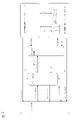
図6に示す例は、左側通交の片側3車線の道路で自車両が右側車線を走行中に、左側車線に存在する分岐地点に向けて2回の車線変更を順次行ない、分岐地点から左側車線の左側に延びる分岐路へ移動する例を示している。ルート走行支援機能は、分岐地点まで第1所定距離以内(例えば、分岐地点まで約2.5km~1.0km手前)であり、かつ、ルート走行提案条件を満たした場合に、右側車線から中央車線への車線変更をルート走行情報により提案する。なお、第1所定距離(車線変更提案区間ともいう)は、走行方向変更地点が存在する車線まで移動するために必要な車線変更の回数に応じて予め設定されている。例えば、図6に示すように、右側車線から中央車線を経て左側車線へ2回の車線変更が必要な場合には、例示したように、分岐地点まで約2.5km~1.0km手前までの区間が第1所定距離(車線変更提案区間)となる。 In the example shown in FIG. 6, while the vehicle is traveling in the right lane on a road with three lanes on one side, the vehicle makes two lane changes in sequence toward a junction in the left lane. It shows an example of moving to a branch road extending to the left of the lane. The route driving support function is within a first predetermined distance to the branch point (for example, about 2.5 km to 1.0 km before the branch point), and when the route travel proposal conditions are satisfied, the route travels from the right lane to the center lane. Based on the route driving information, it proposes a lane change to Note that the first predetermined distance (also referred to as a proposed lane change section) is set in advance according to the number of lane changes required to move to the lane where the travel direction change point exists. For example, as shown in FIG. 6, when it is necessary to change lanes twice from the right lane to the left lane via the center lane, as shown in the example, the distance between about 2.5 km and 1.0 km before the junction is reached. The section becomes the first predetermined distance (lane change proposed section).
なお、ルート走行提案条件として、特に限定されないが、次の条件が全て成立することなどを例示できる。
・ナビゲーション装置15で目的地が設定されている。
・ハンズオフモードのレーンキープモードである。
・速度60km/h以上で走行している。
・車線変更方向に車線がある。
・レーンマーカの種別が車線変更可能である。
・道路の曲率半径が250m以上である。
なお、ルート走行提案条件では、車線変更先に車線変更可能なスペースが存在しない場合でも、ルートに沿った車線変更が必要なことをドライバーに報知するため、ルート走行情報を提示する。In addition, although it is not limited in particular as a route driving|running|working proposal conditions, the following conditions are all satisfied, etc. can be illustrated.
- The destination is set in the navigation device 15 .
・Lane keeping mode in hands-off mode.
・The vehicle is traveling at a speed of 60 km/h or more.
・There is a lane in the lane change direction.
- The type of lane marker can change lanes.
・The radius of curvature of the road is 250m or more.
In the route proposal condition, even if there is no space in the lane change destination, the route information is presented in order to inform the driver that it is necessary to change lanes along the route.
ルート走行支援機能は、ドライバーが分岐地点に向かうための車線変更に承諾し、かつ、ルート走行開始条件を満たした場合に、方向指示器を点灯してLCPを開始する。ルート走行開始条件として、特に限定されないが、次の条件が全て成立することなどを例示できる。
・ハンズオンモードのレーンキープモードである。
・ハンズオン判定中である。
・速度60km/h以上で走行している。
・車線変更方向に車線がある。
・車線変更先の車線に車線変更可能なスペースがある。
・レーンマーカの種別が車線変更可能である。
・車線変更提案区間を走行している。
・道路の曲率半径が250m以上である。The route driving support function turns on the direction indicator and starts the LCP when the driver agrees to change lanes to head to the junction and the conditions for starting route driving are satisfied. The conditions for starting route travel are not particularly limited, but can be exemplified by satisfying all of the following conditions.
・Lane keeping mode in hands-on mode.
・Hands-on judgment is in progress.
・The vehicle is traveling at a speed of 60 km/h or more.
・There is a lane in the lane change direction.
・There is a space in the lane to change lanes.
- The type of lane marker can change lanes.
・You are driving in the proposed lane change section.
・The radius of curvature of the road is 250m or more.
ルート走行支援機能は、ルート走行開始条件を満たした場合にLCPを開始し、中央車線への横移動と、LCMとを実行する。ルート走行支援機能は、LCMが完了すると、方向指示器を消灯し、中央車線でのレーンキープ機能の実行を開始する。ルート走行支援機能は、LCPを実行中に、自動で車線変更を行っていることを表す情報を提示装置16によりドライバーに提示し、周囲への注意を促す。 The route driving support function starts LCP when the route driving start condition is satisfied, and executes lateral movement to the center lane and LCM. When the LCM is completed, the route driving assistance function turns off the direction indicator and starts executing the lane keeping function in the center lane. The route driving support function presents information indicating that the vehicle is automatically changing lanes to the driver by means of the display device 16 while the LCP is being executed, and calls attention to the surroundings.
また、ルート走行支援機能は、図6に示すように、中央車線でのレーンキープ機能の実行中に、分岐地点まで第2所定距離以内(例えば、分岐地点まで約2.3km~700m手前)であり、かつ、ルート走行開始条件を満たした場合に、方向指示器を点灯して2回目のLCPを開始し、中央車線から左側車線へ車線変更を行なう。ルート走行支援機能は、2回目のLCMが完了すると、方向指示器を消灯し、左側車線でのレーンキープ機能の実行を開始する。 Further, as shown in FIG. 6, the route driving support function, during execution of the lane keeping function in the center lane, is within a second predetermined distance to the branch point (for example, about 2.3 km to 700 m before the branch point). If the vehicle is present and the conditions for starting route travel are satisfied, turn on the direction indicator, start the second LCP, and change lanes from the center lane to the left lane. When the second LCM is completed, the route driving assistance function turns off the direction indicator and starts executing the lane keeping function in the left lane.
さらに、ルート走行支援機能は、左側車線でのレーンキープ機能の実行中に、分岐地点まで第3所定距離以内(例えば、分岐地点まで約800m~150m手前)であり、かつ、ルート走行開始条件を満たした場合に、方向指示器を点灯する。また、ルート走行支援機能は、分岐地点を超えた地点から分岐路への自律操舵制御を開始し、左側車線から分岐路へ車線変更を行なう。ルート走行支援機能は、分岐路への車線変更が完了すると、方向指示器を消灯し、分岐路でのレーンキープ機能の実行を開始する。 Further, the route driving support function is, during the execution of the lane keeping function in the left lane, within a third predetermined distance to the branch point (for example, about 800 m to 150 m before the branch point), and the route traveling start condition is satisfied. Lights up the direction indicator when satisfied. In addition, the route driving support function starts autonomous steering control from a point beyond the branch point to the branch road, and changes the lane from the left lane to the branch road. When the lane change to the fork road is completed, the route driving support function turns off the direction indicator and starts executing the lane keep function at the fork road.
図7は、制御装置19に確立された各機能の状態遷移を示すブロック図である。同図に示すシステムとは、制御装置19により実現される自律走行制御システムを意味する。同図に示すシステムOFFの状態から、図2のメインスイッチ171をONすると、当該システムがスタンバイ状態となる。このスタンバイ状態から、図2のセット・コーストスイッチ173又はリジューム・アクセラレートスイッチ172をONすることで、自律速度制御が立ち上がる。これにより、上述した定速制御又は車間制御が開始し、ドライバーはハンドルを操作するだけで、アクセルやブレーキを踏むことなく、自車両を走行させることができる。
FIG. 7 is a block diagram showing state transitions of each function established in the
自律速度制御を実行中に、図7の条件(1)が成立すると自律操舵制御・ハンズオンモードのレーンキープモードに遷移する。この条件(1)としては、特に限定されないが、次の条件が全て成立することなどを例示できる。
・自車両の両側のレーンマーカを検出している。
・ドライバーがハンドルを持っている。
・車線の中央付近を走行している。
・方向指示器が作動していない。
・ワイパーが高速(HI)で作動していない。
・高精度地図がある場合、前方約200m以内に料金所、出口、合流地点、交差点、車線数減少地点がない。If the condition (1) in FIG. 7 is established while the autonomous speed control is being executed, the lane keeping mode of the autonomous steering control/hands-on mode is entered. This condition (1) is not particularly limited, but can be exemplified by satisfying all of the following conditions.
・Lane markers on both sides of the vehicle are detected.
・The driver is holding the steering wheel.
・You are driving near the center of the lane.
・The direction indicator is not working.
・The wipers are not operating at high speed (HI).
・If there is a high-definition map, there are no toll gates, exits, junctions, intersections, or lane reduction points within about 200m ahead.
なお、ハンズオンモードとは、ドライバーがハンドルを持っていないと自律操舵制御が作動しないモードをいい、ハンズオフモードとは、ドライバーがハンドルから手を離しても自律操舵制御が作動するモードをいう。なお、ドライバーによるハンドルの保持は、センサ11のタッチセンサにより検出する。
Hands-on mode is a mode in which autonomous steering control is not activated unless the driver is holding the steering wheel, and hands-off mode is a mode in which autonomous steering control is activated even if the driver releases the steering wheel. It should be noted that the touch sensor of the
自律操舵制御・ハンズオンモードのレーンキープモードを実行中に、図7の条件(2)が成立すると、自律操舵制御・ハンズオフモードのレーンキープモードに遷移する。この条件(2)として、次の条件が全て成立することなどを例示できる。
・自車両が自動車専用道を走行している。
・対向車線と構造的に分離された道路を走行している。
・高精度地図がある道路を走行している。
・制限速度以下の車速で走行している。
・GPS信号が有効である。
・ドライバーがハンドルを持っている。
・ドライバーが前を向いている。
・前方約800m以内に料金所、出口、合流、交差点、車線数減少地点がない。
・前方約500m以内に100R以下の急カーブがない。
・トンネル入り口から500mを超えたトンネル内を走行していない。
・アクセルペダルが踏まれていない。
なお、ドライバーが前を向いているか否かは、例えば、センサ11のドライバーモニターカメラの撮像画像に基づいて判断される。If the condition (2) in FIG. 7 is satisfied while the lane keeping mode of the autonomous steering control/hands-on mode is being executed, the lane keeping mode of the autonomous steering control/hands-off mode is entered. This condition (2) can be exemplified by the fact that all of the following conditions are satisfied.
- The vehicle is traveling on a motorway.
・You are driving on a road that is structurally separated from oncoming traffic.
・You are driving on a road with a high-definition map.
・The vehicle is traveling at a speed below the speed limit.
• GPS signal is valid.
・The driver is holding the steering wheel.
・The driver is facing forward.
・There are no tollgates, exits, confluences, intersections, or lane reduction points within about 800m ahead.
・There is no sharp curve of 100R or less within about 500m ahead.
・Do not drive in a tunnel more than 500m from the tunnel entrance.
・The accelerator pedal is not depressed.
Whether or not the driver is facing forward is determined, for example, based on the captured image of the driver monitor camera of the
逆に、自律操舵制御・ハンズオフモードのレーンキープモードを実行中に、図7の条件(3)が成立すると、自律操舵制御・ハンズオンモードのレーンキープモードに遷移する。この条件(3)として、特に限定されないが、次のいずれかの条件が成立することなどを例示できる。
・自車両が自動車専用道以外の道路を走行している。
・対面通行区間を走行している。
・高精度地図がない道路を走行している。
・制限速度を超えた車速で走行している。
・GPS信号が受信できなくなった。
・前方注視警報が作動した後、ドライバーが5秒以内に前を向かなかった。
・ドライバーモニターカメラで運転者を検知できなくなった。
・前方約800m先に料金所、出口、合流、車線数減少のいずれかがある。
・車速が約40km/h未満で走行している場合、前方約200m以内に100R以下の急カーブがある。
・車速が約40km/h以上で走行している場合、前方約200m以内に170Rの以下急カーブがある。
・トンネル入り口から500mを超えたトンネル内を走行している。
・ドライバーがハンドルを持って、アクセルペダルを踏んでいる。
・接近警報が作動している。Conversely, if the condition (3) in FIG. 7 is satisfied while the lane keep mode of the autonomous steering control/hands-off mode is being executed, the vehicle transitions to the lane keep mode of the autonomous steering control/hands-on mode. The condition (3) is not particularly limited, but can be exemplified by satisfying any of the following conditions.
・The own vehicle is traveling on a road other than an expressway.
・You are driving in a two-way section.
・You are driving on a road without a high-definition map.
・The vehicle is traveling at a speed exceeding the speed limit.
・GPS signals cannot be received.
・The driver did not turn forward within 5 seconds after the forward gaze warning was activated.
・The driver monitor camera can no longer detect the driver.
・There is a tollgate, an exit, a merging, or a decrease in the number of lanes about 800m ahead.
・When the vehicle speed is less than about 40km/h, there is a sharp curve of 100R or less within about 200m ahead.
・When the vehicle speed is about 40km/h or more, there is a sharp curve of 170R or less within about 200m ahead.
・The vehicle is traveling in a tunnel more than 500m from the tunnel entrance.
・The driver is holding the steering wheel and depressing the accelerator pedal.
- Proximity alarm is activated.
自律操舵制御・ハンズオフモードのレーンキープモードを実行中に、図7の条件(4)が成立すると、自律操舵制御を中止して自律速度制御に遷移する。この条件(4)として、特に限定されないが、次のいずれかの条件が成立することなどを例示できる。
・自車両の両側のレーンマーカを一定時間検出しなくなった。
・ドライバーがハンドル操作をしている。
・ワイパーが高速(HI)で作動している。
なお、ドライバーによるハンドル操作は、ハンドルに加えられたトルクを検知することにより判断する。If the condition (4) in FIG. 7 is satisfied while the lane keeping mode of the autonomous steering control/hands-off mode is being executed, the autonomous steering control is stopped and the transition is made to the autonomous speed control. The condition (4) is not particularly limited, but can be exemplified by satisfying any of the following conditions.
・Lane markers on both sides of the vehicle are no longer detected for a certain period of time.
・The driver is operating the steering wheel.
・The wipers are operating at high speed (HI).
The steering wheel operation by the driver is determined by detecting the torque applied to the steering wheel.
また、自律操舵制御・ハンズオフモードのレーンキープモードを実行中に、図7の条件(5)が成立すると、自律操舵制御及び自律速度制御を中止してスタンバイ状態に遷移する。この条件(5)として、特に限定されないが、次のいずれかの条件が成立することなどを例示できる。
・ドライバーがブレーキを操作した。
・ドライバーが図2のキャンセルスイッチ174を操作した。
・自車両のドアが開いた。
・運転席のシートベルトが解除された。
・着座センサでドライバーが運転席からいなくなったことを検知した。
・セレクトレバーが「D」または「M」以外になった。
・パーキングブレーキが作動した。
・車両の横滑り防止装置がOFFになった。
・横滑り防止装置が作動した。
・スノーモードがONにされた。
・エマージェンシーブレーキが作動した。
・車速制御により車両が停止した後、停止状態が約3分継続した。
・前方カメラが、汚れ、逆光、雨・霧などで対象物を正しく認識できないといった視界不良を検出した。
・前方レーダーが遮蔽、電波障害を検出した。
・前方レーダーが軸ずれを検出した。
・側方レーダーが遮蔽、電波障害を検出した。
・側方レーダーが軸ずれを検出した。Further, when the condition (5) in FIG. 7 is satisfied while the lane keeping mode of the autonomous steering control/hands-off mode is being executed, the autonomous steering control and the autonomous speed control are stopped and the state is changed to the standby state. The condition (5) is not particularly limited, but can be exemplified by satisfying any of the following conditions.
・The driver operated the brake.
- The driver operates the cancel
・The door of the vehicle is opened.
- The driver's seat belt has been released.
・The seat sensor detects that the driver has left the driver's seat.
・The selector lever is in a position other than "D" or "M."
・The parking brake is activated.
・The anti-skid system of the vehicle has been turned off.
・The anti-skid system has been activated.
・Snow mode is turned on.
・The emergency brake has been activated.
・After the vehicle was stopped by the vehicle speed control, the stopped state continued for about 3 minutes.
・The front camera detects poor visibility, such as the inability to correctly recognize objects due to dirt, backlight, rain, or fog.
・The forward radar detected shielding and radio interference.
・The forward radar detected an axis misalignment.
・Side radar detected shielding and radio interference.
・The side radar detected an axis misalignment.
自律操舵制御・ハンズオンモードを実行中に、図7の条件(6)が成立すると、自律操舵制御を中止して自律速度制御に遷移する。この条件(6)として、特に限定されないが、次のいずれかの条件が成立することなどを例示できる。
・自車両の両側のレーンマーカを検出しなくなった。
・ドライバーがハンドル操作をした。
・ドライバーが方向指示レバーを操作した。
・ワイパーが高速(HI)で作動した。
・高精度地図がある場合に料金所区間になった。
・前方カメラが、汚れ、逆光、雨・霧などで対象物を正しく認識できない視界不良を検出した。If the condition (6) in FIG. 7 is satisfied while the autonomous steering control/hands-on mode is being executed, the autonomous steering control is stopped and the transition is made to the autonomous speed control. Condition (6) is not particularly limited, but can be exemplified by satisfying any of the following conditions.
・Lane markers on both sides of the vehicle are no longer detected.
・The driver operated the steering wheel.
・The driver operated the direction indicator lever.
・The wiper operated at high speed (HI).
・When there is a high-precision map, it became a tollgate section.
・The front camera detects poor visibility, such as dirt, backlight, rain, or fog, which prevents the vehicle from correctly recognizing objects.
また、自律操舵制御・ハンズオンモードを実行中に、図7の条件(7)が成立すると、自律操舵制御及び自律速度制御を中止してスタンバイ状態に遷移する。この条件(7)として、特に限定されないが、次のいずれかの条件が成立することなどを例示できる。
・ドライバーがブレーキを操作した。
・ドライバーが図2のキャンセルスイッチ174を操作した。
・自車両のドアが開いた。
・運転席のシートベルトが解除された。
・着座センサでドライバーが運転席からいなくなったことを検知した。
・セレクトレバーが「D」または「M」以外になった。
・パーキングブレーキが作動した。
・車両の横滑り防止装置がOFFになった。
・横滑り防止装置が作動した。
・スノーモードがONにされた。
・エマージェンシーブレーキが作動した。
・車速制御により車両が停止した後、停止状態が約3分継続した。
・前方レーダーが遮蔽、電波障害を検出した。
・前方レーダーが軸ずれを検出した。Further, when the condition (7) in FIG. 7 is satisfied while the autonomous steering control/hands-on mode is being executed, the autonomous steering control and the autonomous speed control are stopped and the state is changed to the standby state. This condition (7) is not particularly limited, but can be exemplified by satisfying any of the following conditions.
・The driver operated the brake.
- The driver operates the cancel
・The door of the vehicle is opened.
- The driver's seat belt has been released.
・The seat sensor detects that the driver has left the driver's seat.
・The selector lever is in a position other than "D" or "M."
・The parking brake is activated.
・The anti-skid system of the vehicle has been turned off.
・The anti-skid system has been activated.
・Snow mode is turned on.
・The emergency brake has been activated.
・After the vehicle was stopped by the vehicle speed control, the stopped state continued for about 3 minutes.
・The forward radar detected shielding and radio interference.
・The forward radar detected an axis misalignment.
自律速度制御を実行中に、図7の条件(8)が成立すると、スタンバイ状態に遷移する。この条件(8)として、特に限定されないが、次のいずれかの条件が成立することなどを例示できる。
・ドライバーがブレーキを操作した。
・ドライバーが図2のキャンセルスイッチ174を操作した。
・自車両のドアが開いた。
・運転席のシートベルトが解除された。
・着座センサでドライバーが運転席からいなくなったことを検知した。
・セレクトレバーが「D」または「M」以外になった。
・パーキングブレーキが作動した。
・車両の横滑り防止装置がOFFになった。
・横滑り防止装置が作動した。
・スノーモードがONにされた。
・エマージェンシーブレーキが作動した。
・車速制御により車両が停止した後、停止状態が約3分継続した。
・前方レーダーが遮蔽、電波障害を検出した。
・前方レーダーが軸ずれを検出した。If the condition (8) in FIG. 7 is satisfied while the autonomous speed control is being executed, the state transitions to the standby state. Condition (8) is not particularly limited, but can be exemplified by satisfying any of the following conditions.
・The driver operated the brake.
- The driver operates the cancel
・The door of the vehicle is opened.
- The driver's seat belt has been released.
・The seat sensor detects that the driver has left the driver's seat.
・The selector lever is in a position other than "D" or "M."
・The parking brake is activated.
・The anti-skid system of the vehicle has been turned off.
・The anti-skid system has been activated.
・Snow mode is turned on.
・The emergency brake has been activated.
・After the vehicle was stopped by the vehicle speed control, the stopped state continued for about 3 minutes.
・The forward radar detected shielding and radio interference.
・The forward radar detected an axis misalignment.
自律操舵制御・ハンズオフモードのレーンキープモードを実行中に、図7の条件(9)が成立すると、自律操舵制御・ハンズオンモードのレーンチェンジモードに遷移する。この条件(9)として、特に限定されないが、次のいずれかの条件が成立することなどを例示できる。
・システムが追い越し支援機能又はルート走行支援機能に基づいて車線変更を提案し、ドライバーが車線変更支援スイッチ176を操作した。
・ドライバーが車線変更支援機構を実行するために方向指示レバーを操作した。If the condition (9) in FIG. 7 is satisfied while the lane keep mode of the autonomous steering control/hands-off mode is being executed, the lane change mode of the autonomous steering control/hands-on mode is entered. The condition (9) is not particularly limited, but can be exemplified by satisfying any of the following conditions.
- The system suggested a lane change based on the passing assistance function or the route driving assistance function, and the driver operated the lane
・The driver operated the turn signal lever to activate the lane change assist mechanism.
自律操舵制御・ハンズオンモードのレーンチェンジモードを実行中に、図7の条件(10)が成立すると、自律操舵制御・ハンズオンモードのレーンキープモードに遷移する。この条件(10)として、特に限定されないが、次のいずれかの条件が成立することなどを例示できる。
・LCPの開始前に、制限速度を超えた。
・LCPの開始前に、ドライバーがハンドルを持って、アクセルペダルを踏んだ。
・前方に遅い車がいた場合の車線変更提案中に車線変更支援スイッチ176を押した後、10秒以内にLCPが開始できなかった。
・ルートに従って走行するための車線変更提案中に車線変更支援スイッチ176を押した後、LCPを開始できず分岐地点に近づきすぎてしまった。
・LCPの作動後、5秒以内にLCMを開始できなかった。
・LCPを開始し、LCMを開始する前に車速が約50km/hを下回った。
・LCPが作動した後、LCMを開始する前に車線変更に必要な隣接車線のスペースがなくなった。
・LCM開始前にドライバーがキャンセル操作を行った。
・LCM開始前にレーンマーカが非検知となった。
・LCM開始前に、車線変更する方向に隣接車線がない、または、前方一定距離内にその隣接車線がなくなると判断した。
・LCM開始前に、前方一定距離内に曲率半径250m以上のカーブがあると判断した。
・LCM開始前に、前方一定距離内に区分線の種類がその隣接車線への車線変更禁止している区間があると判断した。
・LCM開始前に、側方レーダーが遮蔽、電波障害を検出した。
・LCM開始前に、側方レーダーが軸ズレを検出した。
・ハンズオン警報が作動したこと。
・ドライバーが方向指示器を停止した。
・LCPが完了した。If the condition (10) in FIG. 7 is satisfied while the lane change mode of the autonomous steering control/hands-on mode is being executed, the lane change mode of the autonomous steering control/hands-on mode is entered. The condition (10) is not particularly limited, but can be exemplified by satisfying any of the following conditions.
• The speed limit was exceeded before the start of the LCP.
・The driver held the steering wheel and stepped on the accelerator pedal before the LCP started.
- The LCP could not be started within 10 seconds after pressing the lane change assist
- After pressing the lane
・The LCM could not be started within 5 seconds after the activation of the LCP.
・The vehicle speed dropped below approximately 50 km/h before the LCP was started and the LCM was started.
- After the LCP has activated, there is no more adjoining lane space to change lanes before the LCM starts.
・The driver performed a cancel operation before the LCM started.
・The lane marker became non-detected before the start of LCM.
・Before the start of the LCM, it was determined that there was no adjacent lane in the direction of the lane change, or that there was no adjacent lane within a certain distance ahead.
・Before starting the LCM, it was determined that there was a curve with a radius of curvature of 250 m or more within a certain distance ahead.
・Before the start of the LCM, it was determined that there was a section within a certain distance in front of the vehicle where the type of lane marking prohibits changing lanes to the adjacent lane.
・Before the start of LCM, the side radar detected shielding and radio interference.
・Before starting the LCM, the side radar detected an axis misalignment.
・The hands-on alarm has been activated.
・The driver turned off the turn signal.
・LCP is completed.
なお、ハンズオン警報は、次のいずれかの条件が成立したときに作動する。
・LCPが作動した後、約2秒以内にドライバーがハンドルを持たなかった。
・前方に遅い車がいた場合の車線変更提案中に車線変更支援スイッチ176を押した後、約2秒以内にドライバーがハンドルを持たなかった。
・ルートに従って走行するための車線変更提案中に車線変更支援スイッチ176を押したのち、約2秒以内にドライバーがハンドルを持たなかった。The hands-on alarm is activated when any of the following conditions are met.
・The driver did not hold the steering wheel within about two seconds after the LCP was activated.
- The driver did not hold the steering wheel within about 2 seconds after pressing the lane
- The driver did not hold the steering wheel within about two seconds after pressing the lane
なお、自律操舵制御・ハンズオフモード、自律操舵制御・ハンズオンモード、自律速度制御、スタンバイ状態のいずれかの状態でメインスイッチ171をOFFすると、システムOFFとなる。
When the
次に、図8を参照して、本実施形態に係る走行制御処理について説明する。図8は、本実施形態に係る走行制御処理を示すフローチャートである。なお、制御装置19は、以下に説明する走行制御処理を所定時間間隔で実行する。また、以下においては、制御装置19の自律走行制御機能により、自律速度制御と自律操舵制御を実行し、車線変更支援機能、追い越し支援機能及びルート走行支援機能をそれぞれ実現する車線変更支援制御、追い越し支援制御及びルート走行支援制御が実行するものとして説明する。
Next, traveling control processing according to the present embodiment will be described with reference to FIG. FIG. 8 is a flowchart showing travel control processing according to the present embodiment. Note that the
まず、図8のステップS1にて、制御装置19のメインスイッチ171がONされているか否かを判定し、メインスイッチ171がOFFである場合はONになるまでステップS1を繰り返す。メインスイッチ171がONである場合はステップS2に進み、ドライバーにより走行速度が設定されているか否かを判定する。走行速度が設定されていない場合はステップS1へ戻り、走行速度が設定されるまでステップS1及びS2を繰り返す。なお、ドライバーによる走行速度の設定は、ドライバーが、図2に示す入力装置17のリジューム・アクセラレートスイッチ172又はセット・コーストスイッチ173を操作して、所望の走行速度を入力することにより行われる。
First, in step S1 of FIG. 8, it is determined whether or not the
走行速度が設定されたら自律速度制御を開始する。ステップS3では、自車両の前方の障害物を検出する前方レーダー(センサ11)を用いて自車両が走行する車線の前方に先行車両が存在するか否かを検出し、先行車両が存在する場合はステップS4へ進んで車間制御を実行する。先行車両が存在しない場合は、ステップS5へ進んで定速制御を実行する。これにより、ドライバーは、ハンドルを操作するだけで、アクセルやブレーキを踏むことなく、自車両を所望の速度で走行させることができる。 Autonomous speed control is started when the traveling speed is set. In step S3, a forward radar (sensor 11) for detecting obstacles in front of the vehicle is used to detect whether or not there is a preceding vehicle in the lane in which the vehicle is traveling. advances to step S4 to execute vehicle-to-vehicle distance control. If there is no preceding vehicle, the routine proceeds to step S5 to execute constant speed control. As a result, the driver can drive the vehicle at a desired speed simply by operating the steering wheel without stepping on the accelerator or brake.
ステップS4の車間制御又はステップS5の定速制御を実行している間に、ステップS6にて、上述した自律操舵制御・ハンズオンモードのレーンキープモードに遷移する条件(1)が成立するか否かを判定する。条件(1)が成立する場合はステップS7へ進み、条件(1)が成立しない場合はステップS3に戻る。 While the vehicle distance control in step S4 or the constant speed control in step S5 is being executed, in step S6, whether or not the condition (1) for transitioning to the autonomous steering control/hands-on mode lane keep mode is established. judge. If the condition (1) is satisfied, the process proceeds to step S7, and if the condition (1) is not satisfied, the process returns to step S3.
ステップS7では、自車両の前方の障害物を検出する前方レーダー(センサ11)を用いて自車両が走行する車線の前方に先行車両が存在するか否かを検出する。先行車両が存在する場合は、ステップS8へ進んで車間制御・レーンキープモードを実行する。先行車両が存在しない場合は、ステップS9へ進んで定速制御・レーンキープモードを実行する。 In step S7, a front radar (sensor 11) for detecting obstacles ahead of the vehicle is used to detect whether or not there is a preceding vehicle ahead of the lane in which the vehicle is traveling. If there is a preceding vehicle, the process proceeds to step S8 to execute the inter-vehicle distance control/lane keep mode. If there is no preceding vehicle, the process proceeds to step S9 to execute the constant speed control/lane keep mode.
ステップS8の車間制御・レーンキープモード又はステップS9の定速制御・レーンキープモードを実行している間に、続くステップS10にて、上述した自動操舵制御・ハンズオフモードに遷移する条件(2)が成立するか否かを判定する。条件(2)が成立する場合はステップS11へ進み、条件(2)が成立しない場合はステップS3に戻る。自律操舵制御・ハンズオフモードに遷移する条件(2)が成立したステップS11では、自車両の前方の障害物を検出する前方レーダー(センサ11)を用いて自車両が走行する車線の前方に先行車両が存在するか否かを検出する。先行車両が存在する場合は、ステップS12へ進んで車間制御・レーンキープモード・ハンズオフを実行する。先行車両が存在しない場合は、ステップS13へ進んで定速制御・レーンキープモード・ハンズオフを実行する。While the vehicle distance control/lane keep mode in step S8 or the constant speed control/lane keep mode in step S9 is being executed, the condition (2) for transitioning to the automatic steering control/hands-off mode described above in step S10. is established. If the condition (2) is satisfied, the process proceeds to step S11, and if the condition (2) is not satisfied, the process returns to step S3. In step S11, when the condition (2) for transitioning to the autonomous steering control/hands-off mode is satisfied, the front radar (sensor 11) that detects obstacles in front of the vehicle is used to move ahead of the lane in which the vehicle is traveling. Detect whether a vehicle is present. If there is a preceding vehicle, the process advances to step S12 to execute inter-vehicle distance control, lane keep mode, and hands-off. If there is no preceding vehicle, the process advances to step S13 to execute constant speed control, lane keep mode, and hands-off.
ステップS14では、ドライバーにより方向指示レバーが操作されたか否かを判断する。方向指示レバーが操作された場合には、自律操舵制御・ハンズオンモードのレーンチェンジモードに遷移する条件(9)が成立してステップS15へ進む。ステップS15では、車線変更支援制御を実行する。ステップS15の車線変更支援制御が完了すると、ステップS3に戻る。ステップS14でドライバーにより方向指示レバーが操作されなかった場合には、ステップS16へ進む。In step S14, it is determined whether or not the driver has operated the direction indicator lever. When the direction indicator lever is operated, the condition (9) for transitioning to the lane change mode of the autonomous steering control /hands-on mode is established, and the process proceeds to step S15. In step S15, lane change support control is executed. When the lane change support control in step S15 is completed, the process returns to step S3. If the driver does not operate the direction indicator lever in step S14, the process proceeds to step S16.
ステップS16では、設定速度よりも遅い先行車両が存在するか否かを判断する。設定速度よりも遅い先行車両が存在する場合には、条件(9)が成立するか否かを判定し、条件(9)が成立する場合には、自律操舵制御・ハンズオンモードのレーンチェンジモードに遷移して、ステップS17へ進む。ステップS17では、追い越し支援制御を実行する。ステップS17の追い越し支援制御が完了すると、ステップS3に戻る。ステップS16で設定速度よりも遅い先行車両が存在しなかった場合には、ステップS18へ進む。In step S16, it is determined whether or not there is a preceding vehicle whose speed is slower than the set speed. If there is a preceding vehicle slower than the set speed , it is determined whether or not condition (9) is met. Transition to step S17. In step S17, overtaking support control is executed. When the overtaking support control in step S17 is completed, the process returns to step S3. If there is no preceding vehicle slower than the set speed in step S16, the process proceeds to step S18.
ステップS18では、ナビゲーション装置15に目的地までのルートが設定されているかを判断する。ルートが設定されていない場合にはステップS1に戻る。ステップS18で、ナビゲーション装置15に目的地までのルートが設定されている場合には、ステップS19へ進む。ステップS19では、ルート上に存在する分岐地点等の走行方向変更地点まで所定距離に到達しているか否かを判断する。ステップS19で走行方向変更地点まで所定距離に到達している場合には、条件(9)が成立するか否かを判定し、条件(9)が成立する場合には、自律操舵制御・ハンズオンモードのレーンチェンジモードに遷移して、ステップS20へ進む。ステップS20では、ルート走行支援制御を実行する。ステップS20のルート走行支援制御が完了すると、ステップS3に戻る。ステップS19で走行方向変更地点まで所定距離に到達していなかった場合には、ステップS1に戻る。In step S18, it is determined whether a route to the destination is set in the navigation device 15. FIG. If the route is not set, return to step S1 . In step S18, when the route to the destination is set in the navigation device 15, the process proceeds to step S19. In step S19, it is determined whether or not the vehicle has reached a predetermined distance to a point where the direction of travel is to be changed, such as a branch point on the route. If it is determined in step S19 that the vehicle has reached the predetermined distance from the point where the traveling direction is to be changed, it is determined whether or not condition (9) is established. If condition (9) is established, autonomous steering control /hands-on mode lane change mode, and proceeds to step S20. In step S20, route driving support control is executed. When the route driving support control in step S20 is completed, the process returns to step S3. If it is determined in step S19 that the predetermined distance has not been reached to the traveling direction change point, the process returns to step S1.
なお、図8のフローチャートでは、車線変更支援制御、追い越し支援制御、ルート走行支援制御の要否を順に判断しているが、実際には各制御の要否を並列に判断しており、いずれかの支援制御の実行中に他の支援制御の実行が必要になった場合には、支援制御同士で実行の要否を調停し、優先的に実行する支援制御を決定する。 In the flowchart of FIG. 8, the necessity of lane change support control, overtaking support control, and route driving support control is determined in order. When it becomes necessary to execute another support control during the execution of the support control of (1), the support controls arbitrate whether or not execution is necessary, and the support control to be executed preferentially is determined.
次に、図8のフローチャートで説明した走行制御の基本的な処理において発生する可能性がある問題を解決する実施形態について説明する。図8のフローチャートで説明した走行制御処理のルート走行支援制御では、例えば、追い越し支援機能による追い越し情報の提示後に、ドライバーにより方向指示レバーが操作されて車線変更支援機構が実行された場合、どちらの支援機能によって車線変更が実行されるか明らかになっていない。また、ドライバーによる追い越し情報への承諾入力後に、ドライバーにより方向指示レバーが操作されて車線変更支援機構が実行された場合、どちらの支援機能によって車線変更が実行されるかも明らかになっていない。このように、追い越し支援機能と車線変更支援機能とが同時に実行された場合、どちらの機能にしたがって車線変更を行うのかが明確でない場合、ドライバーによる車線変更の意思が適切に反映されなくなる。 Next, an embodiment that solves problems that may occur in the basic processing of travel control described in the flowchart of FIG. 8 will be described. In the route driving support control of the driving control process explained in the flow chart of FIG. It is not clear whether lane changes are performed by the assist function. In addition, it is not clear by which support function the lane change is executed when the driver operates the direction indicator lever and the lane change support mechanism is executed after the driver inputs consent to the overtaking information. In this way, when the overtaking support function and the lane change support function are executed at the same time, if it is not clear which function the lane change is to be performed according to, the driver's intention to change the lane will not be properly reflected.
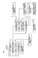
本実施形態では、上述した問題の発生を防ぐため、図9に示すフローチャートのような制御を行う。ステップS30で追い越し支援機能による追い越し情報が提示され、ステップS31で追い越し情報に対する承諾入力が行われずに、ステップS32で方向指示レバーが操作された場合、ステップS33では、車線変更支援機能による車線変更が実行される。これにより、ドライバーによる車線変更の意思が優先される。 In this embodiment, control as shown in the flowchart of FIG. 9 is performed in order to prevent the above-described problem from occurring. If the overtaking information by the overtaking support function is presented in step S30 and the direction indicator lever is operated in step S32 without inputting consent to the overtaking information in step S31, the lane change by the lane change support function is performed in step S33. executed. This gives priority to the intention of the driver to change lanes.
また、ステップS31で追い越し情報に対する承諾入力が行われた後に、ステップS34で追い越し開始条件が成立する前に、ステップS35で方向指示レバーが操作された場合はステップS36に進む。このステップS36では、追い越し情報の車線変更方向と、方向指示レバーの操作方向とが同一であるか否かを判定する。追い越し情報の車線変更方向と、方向指示レバーの操作方向とが同一である場合、ステップS37に進み、追い越し支援機能による車線変更に代えて、車線変更支援機能による車線変更が実行される。これにより、ドライバーの意思が優先される。なお、この場合には、ドライバーによる車線変更の意思を優先して、ステップS39では、車線変更先の車線から元の車線へ戻るための前記車線変更情報の提示を行わない。 Also, if the direction indicator lever is operated in step S35 before the overtaking start condition is satisfied in step S34 after the acceptance of the overtaking information is input in step S31, the process proceeds to step S36. In this step S36, it is determined whether or not the lane change direction of the overtaking information is the same as the operation direction of the direction indicator lever. If the lane change direction of the overtaking information is the same as the operation direction of the direction indicator lever, the process proceeds to step S37, and the lane change is performed by the lane change support function instead of the lane change by the overtaking support function. This gives priority to the driver's intention. In this case, priority is given to the driver's intention to change lanes, and in step S39, the lane change information for returning from the destination lane to the original lane is not presented.
これとは逆に、ステップS36で追い越し情報の車線変更方向と、方向指示レバーの操作方向とが同一ではなかった場合、ステップS38で承諾入力はキャンセルされたものと判定して、追い越し支援機能による車線変更が中止される。 Conversely, if the lane change direction of the overtaking information and the operation direction of the direction indicator lever are not the same in step S36, it is determined that the consent input has been canceled in step S38, and the overtaking support function is performed. Lane change aborted.
また、ステップS35で方向指示レバーが操作されず、ステップS40で車線変更支援スイッチの操作後に所定時間が経過した場合には、ステップS38で追い越し支援機能による車線変更が中止される。この所定時間は、所定の閾値を用いてもよいし、例えば、追い越し支援機能が実行された理由に基づいて変更してもよい。例えば、先行車両の速度が遅いため、その先行車両を追い越す場合には、所定時間を10秒程度とし、ルート走行支援機能によってルートに沿って進むために必要な車線変更の場合は、2分30秒程度等である。 If the direction indicator lever is not operated in step S35 and the predetermined time has elapsed after the lane change support switch is operated in step S40, the lane change by the overtaking support function is canceled in step S38. This predetermined period of time may be a predetermined threshold value, or may be changed, for example, based on the reason why the overtaking assistance function was performed. For example, when overtaking the preceding vehicle because the speed of the preceding vehicle is slow, the predetermined time is set to about 10 seconds, and in the case of a lane change required to proceed along the route by the route driving support function, 2 minutes and 30 minutes. Seconds or so.
以上のように、本実施形態に係る車両の走行制御装置1及び走行制御方法によれば、車線変更を実行するための所定の条件が成立した場合に、車両に自律走行制御による車線変更を行わせる自動車線変更機能の実行を承諾するか否かの車線変更情報をドライバーに提示し、車線変更情報の提示に対し、ドライバーによる、自動車線変更機能の実行を承諾する旨の承諾入力が検知された場合に、自動車線変更機能を実行するシステムトリガモードと、ドライバーにより、承諾入力とは異なる車線変更指示操作が行われた場合に、自動車線変更機能を実行するドライバートリガモードと、を備え、車線変更情報の提示後に、ドライバーにより車線変更指示操作が行われた場合に、ドライバートリガモードによる自動車線変更機能を実行する。これにより、システムトリガモードによる車線変更の提案があった場合でも、ドライバーの車線変更の意思を優先してドライバートリガモードによる自動車線変更機能を実行することができる。
As described above, according to the vehicle
また、車線変更を実行するための所定の条件が成立した場合に、車両に自律走行制御による車線変更を行わせる自動車線変更機能の実行を承諾するか否かの車線変更情報をドライバーに提示し、車線変更情報の提示に対し、ドライバーによる、自動車線変更機能の実行を承諾する旨の承諾入力が検知された場合に、自動車線変更機能を実行するシステムトリガモードと、ドライバーにより、承諾入力とは異なる所定の車線変更指示操作が行われた場合に、自動車線変更機能を実行するドライバートリガモードと、を備え、ドライバーによる承諾入力後に、車線変更指示操作が行われた場合に、車線変更情報で提示された車線変更方向と、車線変更指示操作で指示された車線変更方向とが同一方向の場合には、システムトリガモードによる自動車線変更機能に代えて、ドライバートリガモードによる自動車線変更機能を実行する。また、車線変更情報で提示された車線変更方向と、車線変更指示操作で指示された車線変更方向とが逆方向の場合には、承諾入力をキャンセルする。これにより、ドライバーがシステムトリガモードによる車線変更の提案を承諾した場合でも、ドライバーの車線変更の意思を優先してドライバートリガモードによる自動車線変更機能を実行することができる。 In addition, when a predetermined condition for executing a lane change is satisfied, the driver is presented with lane change information indicating whether or not to approve the execution of an automatic lane change function that causes the vehicle to change lanes by autonomous driving control. , in response to the presentation of the lane change information, a system trigger mode that executes the auto lane change function when the driver's consent input to consent to the execution of the auto lane change function is detected; and a driver trigger mode for executing an automatic lane change function when a different predetermined lane change instruction operation is performed, and when the lane change instruction operation is performed after the driver's consent input, the lane change information If the lane change direction presented in and the lane change direction instructed by the lane change instruction operation are the same, the automatic lane change function by the driver trigger mode is used instead of the automatic lane change function by the system trigger mode. Run. Also, when the lane change direction presented by the lane change information and the lane change direction instructed by the lane change instruction operation are opposite directions, the approval input is canceled. As a result, even if the driver accepts the lane change proposal in the system trigger mode, the automatic lane change function in the driver trigger mode can be executed with priority given to the driver's lane change intention.
システムトリガモードによる自動車線変更機能に代えて、ドライバートリガモードによる自動車線変更機能を実行する場合には、車線変更先の車線から元の車線へ戻るための車線変更情報の提示を行わないので、ドライバーの車線変更の意思を優先して、車線変更先の車線での走行を継続することができる。 When executing the automatic lane change function in the driver trigger mode instead of the automatic lane change function in the system trigger mode, lane change information for returning from the destination lane to the original lane is not presented. Priority is given to the intention of the driver to change lanes, and the vehicle can continue to travel in the new lane.
また、承諾入力には、ドライバーがハンドルを保持したまま操作が可能な操作部が用い、車線変更指示操作には、方向指示レバーが用いられるので、システムトリガモードに対する承諾と、ドライバーの意思に基づく車線変更とを明確に分けて操作することができ、誤操作の発生を防止することができる。 In addition, an operation unit that can be operated by the driver while holding the steering wheel is used for consent input, and a direction indicator lever is used for lane change instruction operation. The operation can be clearly separated from the lane change, and the occurrence of erroneous operation can be prevented.
1…走行制御装置
11…センサ
12…自車位置検出装置
13…地図データベース
14…車載機器
15…ナビゲーション装置
16…提示装置
17…入力装置
171…メインスイッチ
172…リジューム・アクセラレートスイッチ
173…セット・コーストスイッチ
174…キャンセルスイッチ
175…車間調整スイッチ
176…車線変更支援スイッチ
177…表示画面
178…ONボタン
179…OFFボタン
18…駆動制御装置
19…制御装置DESCRIPTION OF
Claims (5)
前記システムトリガモードは、
前記自動車線変更機能の開始条件が成立したか否かを判定し、
前記開始条件が成立した場合に、車線変更を行うか否かの車線変更情報を提示し、
前記車線変更情報の提示に対し、車線変更を行うことを承諾する旨の承諾入力が検知された場合に、前記車線変更情報で提案された車線変更を、前記自動車線変更機能により実行し、
前記ドライバートリガモードは、
ドライバーにより前記承諾入力とは異なる車線変更指示操作が行われたか否かを検知し、
前記車線変更指示操作が行われたことを検知した場合に、前記車線変更指示操作で指示された車線変更を、前記自動車線変更機能により実行し、
前記システムトリガモードにおいて、前記車線変更情報が提示された後に、ドライバーによる前記車線変更指示操作を検知した場合には、前記ドライバートリガモードにより、前記車線変更指示操作で指示された車線変更を実行する車両の走行制御方法。A system trigger mode in which a lane change proposed by the autonomous driving control system of the vehicle is executed by autonomous driving control by the automatic lane change function, and a lane change instructed by the driver of the vehicle is executed by the automatic lane change function. A driving control method for a vehicle comprising a driver trigger mode,
The system trigger mode is
determining whether or not a condition for starting the automatic lane change function is established;
When the start condition is satisfied, presenting lane change information as to whether or not to change lanes,
When an approval input to the effect that the lane change is accepted is detected in response to the presentation of the lane change information, the lane change proposed by the lane change information is performed by the automatic lane change function,
The driver trigger mode is
Detecting whether or not a lane change instruction operation different from the consent input has been performed by the driver,
When it is detected that the lane change instruction operation has been performed, the lane change instructed by the lane change instruction operation is performed by the automatic lane change function,
In the system trigger mode, when the lane change instruction operation by the driver is detected after the lane change information is presented, the lane change instructed by the lane change instruction operation is executed in the driver trigger mode. Vehicle travel control method.
前記承諾入力とは異なる所定の車線変更指示操作が行われた場合に、前記自動車線変更機能を実行するドライバートリガモードと、を備え、
前記承諾入力の後に、前記車線変更指示操作が行われた場合に、前記車線変更情報で提示された車線変更方向と、前記車線変更指示操作で指示された車線変更方向とが同一方向であるか否かを判定し、
前記車線変更情報で提示された車線変更方向と、前記車線変更指示操作で指示された車線変更方向とが同一方向である場合には、前記システムトリガモードによる前記自動車線変更機能に代えて、前記ドライバートリガモードによる前記自動車線変更機能を実行し、
前記車線変更情報で提示された車線変更方向と、前記車線変更指示操作で指示された車線変更方向とが逆方向の場合には、前記承諾入力をキャンセルする車両の走行制御方法。When a condition for starting an auto lane change function that causes the vehicle to change lanes by autonomous driving control is met, lane change information indicating whether or not to approve the execution of the auto lane change function is presented, and the lane change information is presented. a system trigger mode for executing the automatic lane change function when an approval input to the effect that the execution of the automatic lane change function is accepted is detected for the automatic lane change function;
a driver trigger mode for executing the auto lane change function when a predetermined lane change instruction operation different from the consent input is performed;
If the lane change instruction operation is performed after the consent input, is the lane change direction presented by the lane change information and the lane change direction instructed by the lane change instruction operation the same direction? determine whether or not
When the lane change direction presented by the lane change information and the lane change direction instructed by the lane change instruction operation are the same direction, instead of the automatic lane change function by the system trigger mode, the executing the auto lane change function in driver-triggered mode;
A vehicle running control method for canceling the approval input when the lane change direction indicated by the lane change information and the lane change direction instructed by the lane change instruction operation are opposite directions.
前記車線変更指示操作には、方向指示レバーが用いられる請求項1~3のいずれか1項に記載の車両の走行制御方法。A switch that can be pressed while holding the handle is used for the consent input,
The vehicle travel control method according to any one of claims 1 to 3, wherein a direction indicating lever is used for the lane change instruction operation.
前記自動車線変更機能の開始条件の成立を判定する条件判定部と、
前記開始条件が成立した場合に、車線変更を行うか否かの車線変更情報を提示する提示部と、
前記車線変更情報の提示に対し、車線変更を行うことを承諾する旨の操作が行われる承諾入力部と、
ドライバーにより操作され、前記承諾入力部とは異なる車線変更指示操作が行われる車線変更指示部と、
前記承諾入力部の操作を検知した場合に、前記車線変更情報で提案した車線変更を前記自動車線変更機能により実行するシステムトリガモードと、前記車線変更指示部の操作を検知した場合に、前記車線変更指示部により指示された車線変更を前記自動車線変更機能により実行するドライバートリガモードとを切り替える制御部と、を備え、
前記制御部は、前記システムトリガモードにおいて、前記車線変更情報が提示された後に、ドライバーによる前記車線変更指示部の操作を検知した場合には、前記ドライバートリガモードにより、前記車線変更指示部で指示された車線変更を実行する車両の走行制御装置。A system trigger mode in which a lane change proposed by the autonomous driving control system of the vehicle is executed by autonomous driving control by the automatic lane change function, and a lane change instructed by the driver of the vehicle is executed by the automatic lane change function. A vehicle cruise control device comprising a driver trigger mode,
a condition determination unit that determines whether a condition for starting the automatic lane change function is met;
a presentation unit that presents lane change information indicating whether or not to change lanes when the start condition is satisfied;
a consent input unit for performing an operation to consent to the lane change in response to the presentation of the lane change information;
A lane change instruction unit operated by a driver to perform a lane change instruction operation different from the consent input unit;
When the operation of the consent input unit is detected, a system trigger mode in which the lane change proposed by the lane change information is executed by the automatic lane change function, and when the operation of the lane change instruction unit is detected, the lane a control unit that switches between a driver trigger mode in which the lane change instructed by the change instruction unit is executed by the automatic lane change function,
In the system trigger mode, when the controller detects an operation of the lane change instruction unit by the driver after the lane change information is presented, the control unit instructs the lane change instruction unit in the driver trigger mode. A vehicle cruise control device that performs a controlled lane change.
Applications Claiming Priority (1)
| Application Number | Priority Date | Filing Date | Title |
|---|---|---|---|
| PCT/JP2019/019390 WO2020230304A1 (en) | 2019-05-15 | 2019-05-15 | Vehicle travel control method and travel control device |
Publications (3)
| Publication Number | Publication Date |
|---|---|
| JPWO2020230304A1 JPWO2020230304A1 (en) | 2020-11-19 |
| JPWO2020230304A5 JPWO2020230304A5 (en) | 2022-03-16 |
| JP7156517B2 true JP7156517B2 (en) | 2022-10-19 |
Family
ID=73289154
Family Applications (1)
| Application Number | Title | Priority Date | Filing Date |
|---|---|---|---|
| JP2021519214A Active JP7156517B2 (en) | 2019-05-15 | 2019-05-15 | VEHICLE TRIP CONTROL METHOD AND TRIP CONTROL DEVICE |
Country Status (5)
| Country | Link |
|---|---|
| US (1) | US11505194B2 (en) |
| EP (1) | EP3971860A4 (en) |
| JP (1) | JP7156517B2 (en) |
| CN (1) | CN113811934B (en) |
| WO (1) | WO2020230304A1 (en) |
Families Citing this family (5)
| Publication number | Priority date | Publication date | Assignee | Title |
|---|---|---|---|---|
| JP6907285B2 (en) * | 2019-10-11 | 2021-07-21 | 本田技研工業株式会社 | Vehicle control devices, vehicle control methods, and programs |
| JP6946496B2 (en) * | 2020-03-04 | 2021-10-06 | 本田技研工業株式会社 | Vehicle control device and vehicle control method |
| JP7474136B2 (en) * | 2020-06-30 | 2024-04-24 | 本田技研工業株式会社 | Control device, control method, and program |
| CN114194193B (en) * | 2021-01-11 | 2023-06-27 | 广东科学技术职业学院 | Method for controlling lane change of vehicle |
| US20230237904A1 (en) * | 2022-01-24 | 2023-07-27 | Qualcomm Incorporated | Smart traffic management |
Citations (4)
| Publication number | Priority date | Publication date | Assignee | Title |
|---|---|---|---|---|
| JP2016197390A (en) | 2015-04-03 | 2016-11-24 | 株式会社デンソー | Start-up suggestion device and start-up suggestion method |
| JP2018030479A (en) | 2016-08-25 | 2018-03-01 | スズキ株式会社 | Travel control device of vehicle |
| JP2018092538A (en) | 2016-12-07 | 2018-06-14 | トヨタ自動車株式会社 | Vehicle travel controller |
| JP2019043432A (en) | 2017-09-05 | 2019-03-22 | 本田技研工業株式会社 | Vehicle control system, vehicle control method and program |
Family Cites Families (15)
| Publication number | Priority date | Publication date | Assignee | Title |
|---|---|---|---|---|
| JP4329088B2 (en) | 1998-02-18 | 2009-09-09 | 株式会社エクォス・リサーチ | Vehicle control device |
| US6577334B1 (en) | 1998-02-18 | 2003-06-10 | Kabushikikaisha Equos Research | Vehicle control |
| JP4565420B2 (en) | 2000-11-22 | 2010-10-20 | マツダ株式会社 | Lane departure prevention device |
| MX358325B (en) * | 2014-03-26 | 2018-08-15 | Nissan Motor | Information presentation device and information presentation method. |
| JP6103716B2 (en) * | 2014-06-17 | 2017-03-29 | 富士重工業株式会社 | Vehicle travel control device |
| JP6418634B2 (en) * | 2014-09-29 | 2018-11-07 | 株式会社Subaru | Driving support control device |
| JP5970513B2 (en) * | 2014-09-29 | 2016-08-17 | 富士重工業株式会社 | Driving support control device |
| JP6332170B2 (en) * | 2015-07-01 | 2018-05-30 | トヨタ自動車株式会社 | Automatic operation control device |
| EP3150465B1 (en) * | 2015-10-01 | 2018-12-12 | Volvo Car Corporation | Method and system for indicating a potential lane shift of a vehicle |
| JP6517161B2 (en) * | 2016-02-18 | 2019-05-22 | 本田技研工業株式会社 | Traveling control device |
| JP6464107B2 (en) * | 2016-02-22 | 2019-02-06 | 本田技研工業株式会社 | Driving support device |
| US10328973B2 (en) * | 2017-03-06 | 2019-06-25 | Ford Global Technologies, Llc | Assisting drivers with roadway lane changes |
| JP6693447B2 (en) * | 2017-03-13 | 2020-05-13 | 株式会社デンソー | Travel control device |
| JP6568559B2 (en) * | 2017-09-13 | 2019-08-28 | 株式会社Subaru | Vehicle travel control device |
| JP7115184B2 (en) * | 2018-09-26 | 2022-08-09 | トヨタ自動車株式会社 | Autonomous driving system |
-
2019
- 2019-05-15 JP JP2021519214A patent/JP7156517B2/en active Active
- 2019-05-15 US US17/609,833 patent/US11505194B2/en active Active
- 2019-05-15 WO PCT/JP2019/019390 patent/WO2020230304A1/en unknown
- 2019-05-15 CN CN201980096246.4A patent/CN113811934B/en active Active
- 2019-05-15 EP EP19928313.6A patent/EP3971860A4/en active Pending
Patent Citations (4)
| Publication number | Priority date | Publication date | Assignee | Title |
|---|---|---|---|---|
| JP2016197390A (en) | 2015-04-03 | 2016-11-24 | 株式会社デンソー | Start-up suggestion device and start-up suggestion method |
| JP2018030479A (en) | 2016-08-25 | 2018-03-01 | スズキ株式会社 | Travel control device of vehicle |
| JP2018092538A (en) | 2016-12-07 | 2018-06-14 | トヨタ自動車株式会社 | Vehicle travel controller |
| JP2019043432A (en) | 2017-09-05 | 2019-03-22 | 本田技研工業株式会社 | Vehicle control system, vehicle control method and program |
Also Published As
| Publication number | Publication date |
|---|---|
| CN113811934A (en) | 2021-12-17 |
| US20220203993A1 (en) | 2022-06-30 |
| JPWO2020230304A1 (en) | 2020-11-19 |
| EP3971860A4 (en) | 2022-12-14 |
| US11505194B2 (en) | 2022-11-22 |
| CN113811934B (en) | 2022-11-04 |
| EP3971860A1 (en) | 2022-03-23 |
| WO2020230304A1 (en) | 2020-11-19 |
Similar Documents
| Publication | Publication Date | Title |
|---|---|---|
| JP7140277B2 (en) | VEHICLE TRIP CONTROL METHOD AND TRIP CONTROL DEVICE | |
| JP7143946B2 (en) | VEHICLE TRIP CONTROL METHOD AND TRIP CONTROL DEVICE | |
| JP7156517B2 (en) | VEHICLE TRIP CONTROL METHOD AND TRIP CONTROL DEVICE | |
| JP7347503B2 (en) | Vehicle running control method and running control device | |
| JP7164030B2 (en) | VEHICLE TRIP CONTROL METHOD AND TRIP CONTROL DEVICE | |
| JP7331450B2 (en) | VEHICLE TRIP CONTROL METHOD AND TRIP CONTROL DEVICE | |
| JP7434866B2 (en) | Vehicle travel control method and travel control device | |
| JP7156516B2 (en) | VEHICLE TRIP CONTROL METHOD AND TRIP CONTROL DEVICE | |
| US20230347926A1 (en) | Driving control method and driving control device | |
| WO2023089837A1 (en) | Travel assistance method and travel assistance device for vehicle | |
| WO2023089835A1 (en) | Vehicle travel assistance method and vehicle travel assistance device | |
| JP7211552B2 (en) | VEHICLE TRIP CONTROL METHOD AND TRIP CONTROL DEVICE | |
| RU2780638C1 (en) | Vehicle motion control method and motion control device | |
| RU2780639C1 (en) | Motion control method and motion control device for a vehicle | |
| RU2774085C1 (en) | Vehicle traffic control method and vehicle traffic control device | |
| RU2774335C1 (en) | Vehicle traffic control method and vehicle traffic control device | |
| RU2773993C1 (en) | Method for traffic control and traffic control device for vehicle | |
| WO2021106146A1 (en) | Traveling control method and traveling control device for vehicle |
Legal Events
| Date | Code | Title | Description |
|---|---|---|---|
| A529 | Written submission of copy of amendment under article 34 pct |
Free format text: JAPANESE INTERMEDIATE CODE: A5211 Effective date: 20211028 |
|
| A621 | Written request for application examination |
Free format text: JAPANESE INTERMEDIATE CODE: A621 Effective date: 20211028 |
|
| A521 | Request for written amendment filed |
Free format text: JAPANESE INTERMEDIATE CODE: A523 Effective date: 20211101 |
|
| TRDD | Decision of grant or rejection written | ||
| A01 | Written decision to grant a patent or to grant a registration (utility model) |
Free format text: JAPANESE INTERMEDIATE CODE: A01 Effective date: 20220906 |
|
| A61 | First payment of annual fees (during grant procedure) |
Free format text: JAPANESE INTERMEDIATE CODE: A61 Effective date: 20220919 |
|
| R151 | Written notification of patent or utility model registration |
Ref document number: 7156517 Country of ref document: JP Free format text: JAPANESE INTERMEDIATE CODE: R151 |