WO2023145638A1 - Ophthalmic device and ophthalmic program - Google Patents
Ophthalmic device and ophthalmic program Download PDFInfo
- Publication number
- WO2023145638A1 WO2023145638A1 PCT/JP2023/001678 JP2023001678W WO2023145638A1 WO 2023145638 A1 WO2023145638 A1 WO 2023145638A1 JP 2023001678 W JP2023001678 W JP 2023001678W WO 2023145638 A1 WO2023145638 A1 WO 2023145638A1
- Authority
- WO
- WIPO (PCT)
- Prior art keywords
- eye
- measurement
- face
- image
- position information
- Prior art date
Links
Images


Classifications
-
- A—HUMAN NECESSITIES
- A61—MEDICAL OR VETERINARY SCIENCE; HYGIENE
- A61B—DIAGNOSIS; SURGERY; IDENTIFICATION
- A61B3/00—Apparatus for testing the eyes; Instruments for examining the eyes
- A61B3/10—Objective types, i.e. instruments for examining the eyes independent of the patients' perceptions or reactions
- A61B3/103—Objective types, i.e. instruments for examining the eyes independent of the patients' perceptions or reactions for determining refraction, e.g. refractometers, skiascopes
-
- A—HUMAN NECESSITIES
- A61—MEDICAL OR VETERINARY SCIENCE; HYGIENE
- A61B—DIAGNOSIS; SURGERY; IDENTIFICATION
- A61B3/00—Apparatus for testing the eyes; Instruments for examining the eyes
- A61B3/10—Objective types, i.e. instruments for examining the eyes independent of the patients' perceptions or reactions
- A61B3/113—Objective types, i.e. instruments for examining the eyes independent of the patients' perceptions or reactions for determining or recording eye movement
Landscapes
- Health & Medical Sciences (AREA)
- Life Sciences & Earth Sciences (AREA)
- Engineering & Computer Science (AREA)
- Heart & Thoracic Surgery (AREA)
- Molecular Biology (AREA)
- Biophysics (AREA)
- Ophthalmology & Optometry (AREA)
- Biomedical Technology (AREA)
- Veterinary Medicine (AREA)
- Medical Informatics (AREA)
- Physics & Mathematics (AREA)
- Surgery (AREA)
- Animal Behavior & Ethology (AREA)
- General Health & Medical Sciences (AREA)
- Public Health (AREA)
- Human Computer Interaction (AREA)
- Eye Examination Apparatus (AREA)
Abstract
Provided is an ophthalmic device for objectively measuring the optical characteristics of an eye to be tested, the ophthalmic device being provided with a face imaging means for capturing a face image of a subject and an eye position information acquisition means for acquiring eye position information on the eye to be tested on the basis of the face image captured by the face imaging means. A measurement means for measuring the optical characteristics of the eye to be tested measures on a measurement eye that is one of a right eye and a left eye, the face imaging means captures a face image including a non-measurement eye that is the other of the right eye and the left eye and is different from the measurement eye, and the eye position information acquisition means acquires the eye position information on at least the non-measurement eye on the basis of the face image including the non-measurement eye.
Description
本開示は、被検眼の光学特性を他覚的に測定する眼科装置及び眼科プログラムに関する。
The present disclosure relates to an ophthalmic device and an ophthalmic program for objectively measuring optical characteristics of an eye to be examined.
眼科装置として、例えば、被検眼の眼底に測定光束を投影し、その眼底反射光束を受光することにより、被検眼の光学特性を測定するものが知られている(特許文献1参照)。
As an ophthalmologic apparatus, for example, there is known one that measures the optical characteristics of a subject's eye by projecting a measurement light flux onto the fundus of the subject's eye and receiving the reflected light flux of the subject's eye (see Patent Document 1).
近年は若年層を中心とする眼位異常の増加がみられており、検者あるいは被検者の目的や用途に応じた様々な場面で、眼位情報が必要になると考えられる。このため、発明者らは、被検眼の光学特性とともに眼位情報を取得するための装置構成を検討した。
In recent years, there has been an increase in eye position abnormalities, mainly among young people, and it is thought that eye position information will be necessary in various situations depending on the purpose and application of the examiner or examinee. For this reason, the inventors have studied an apparatus configuration for acquiring the eye position information together with the optical characteristics of the subject's eye.
本開示は上記の問題点を鑑み、被検眼の眼位情報を取得できる眼科装置及び眼科プログラムを提供することを技術課題とする。
In view of the above problems, the technical problem of the present disclosure is to provide an ophthalmologic apparatus and an ophthalmologic program capable of acquiring eye position information of an eye to be examined.
本開示の第1態様に係る眼科装置は、被検眼の光学特性を他覚的に測定する眼科装置であって、被検者の顔画像を撮影する顔撮影手段と、前記顔撮影手段が撮影した前記顔画像に基づいて、被検眼の眼位情報を取得する眼位情報取得手段と、を備えることを特徴とする。
An ophthalmologic apparatus according to a first aspect of the present disclosure is an ophthalmologic apparatus that objectively measures optical characteristics of an eye to be examined, comprising: face imaging means for imaging a face image of a subject; eye position information acquisition means for acquiring eye position information of the eye to be inspected based on the face image thus obtained.
本開示の第2態様に係る眼科プログラムは、被検眼の光学特性を他覚的に測定する眼科装置にて用いる眼科プログラムであって、前記眼科装置のプロセッサに実行されることで、被検者の顔画像を撮影する顔撮影ステップと、前記顔撮影ステップで撮影された前記顔画像に基づいて、被検眼の眼位情報を取得する眼位情報取得ステップと、を前記眼科装置に実行させることを特徴とする。
An ophthalmologic program according to a second aspect of the present disclosure is an ophthalmologic program used in an ophthalmologic apparatus that objectively measures optical characteristics of an eye to be examined, and is executed by a processor of the ophthalmologic apparatus to provide a subject with and an eye position information acquiring step of acquiring eye position information of the subject's eye based on the face image captured in the face capturing step. characterized by
<概要>
本開示の実施形態に係る眼科装置の概要について説明する。以下の<>にて分類された項目は、独立または関連して利用され得る。なお、本実施形態における「共役」とは、必ずしも完全な共役関係に限定されるものではなく、「略共役」を含むものとする。すなわち、本実施形態の「共役」には、各部の技術意義との関係で許容される範囲で、完全な共役位置からずれて配置される場合も含まれる。 <Overview>
An outline of an ophthalmologic apparatus according to an embodiment of the present disclosure will be described. The items classified in <> below can be used independently or in conjunction with each other. It should be noted that the term “conjugated” in the present embodiment is not necessarily limited to a perfect conjugated relationship, but includes “substantially conjugated”. That is, the term "conjugated" in the present embodiment also includes the case where each part is displaced from the perfectly conjugated position within the range allowed in relation to the technical significance of each part.
<眼科装置>
本実施形態の眼科装置は、被検眼の光学特性を他覚的に測定する。被検眼の光学特性は、眼屈折力(例えば、球面度数、円柱度数、乱視軸角度、等)、両眼視機能(例えば、斜位量、立体視機能、等)、コントラスト感度、眼軸長、角膜形状、等であってもよい。 <Ophthalmic device>
The ophthalmologic apparatus of this embodiment objectively measures the optical characteristics of the subject's eye. The optical characteristics of the eye to be examined include ocular refractive power (e.g., spherical power, cylindrical power, astigmatism axis angle, etc.), binocular vision function (e.g., oblique amount, stereoscopic vision function, etc.), contrast sensitivity, and axial length. , corneal shape, and the like.
<顔撮影手段>
本実施形態の眼科装置は、顔撮影手段を備えてもよい。顔撮影手段は、被検者の顔画像を撮影する。 <Face shooting means>
The ophthalmologic apparatus of the present embodiment may include face imaging means. The face photographing means photographs a face image of the subject.
本実施形態の眼科装置は、顔撮影手段を備えてもよい。顔撮影手段は、被検者の顔画像を撮影する。 <Face shooting means>
The ophthalmologic apparatus of the present embodiment may include face imaging means. The face photographing means photographs a face image of the subject.
顔撮影手段は、被検眼のうち、右眼及び左眼の少なくとも一方を含む顔画像を撮影してもよい。すなわち、右眼と左眼のいずれか一方を含む顔の一部の画像を撮影してもよいし、右眼と左眼の双方を含む顔の全体の画像を撮影してもよい。好ましくは、右眼と左眼の双方の撮影が可能な画角で、顔画像を撮影できる構成であるとよい。
The face photographing means may photograph a face image including at least one of the right eye and the left eye among the eyes to be examined. That is, an image of a part of the face including either one of the right eye and the left eye may be captured, or an image of the entire face including both the right eye and the left eye may be captured. Preferably, the configuration is such that a face image can be captured at an angle of view that allows capturing of both the right eye and the left eye.
顔撮影手段は、顔撮影手段を構成する一部として、顔照明光学系(例えば、顔照明光学系600)を備えてもよい。顔照明光学系は、被検者の顔に向けて照明光束を出射することで、顔を照明してもよい。例えば、顔照明光学系は、少なくとも光源を有する構成であればよい。
The face photographing means may include a face illumination optical system (for example, face illumination optical system 600) as a part of the face photographing means. The face illumination optical system may illuminate the subject's face by emitting an illumination light beam toward the subject's face. For example, the face illumination optical system may have at least a light source.
顔撮影手段は、顔撮影手段を構成する一部として、顔撮影光学系(例えば、顔撮影光学系700)を備えてもよい。顔撮影光学系は、被検者の顔からの反射光束を受光することで、顔を撮影する。例えば、自然光の反射光束を受光して、顔を撮影してもよい。また、例えば、顔照明光学系を備える場合には、顔照明光学系の光源から出射された照明光束の反射光束を受光して、顔を撮影してもよい。例えば、顔撮影光学系は、少なくとも撮像素子を有する構成であればよい。
The face photographing means may include a face photographing optical system (for example, the face photographing optical system 700) as a part of the face photographing means. The face imaging optical system captures an image of the subject's face by receiving reflected light beams from the subject's face. For example, a reflected light flux of natural light may be received to photograph a face. Further, for example, when a face illumination optical system is provided, the face may be photographed by receiving a reflected light flux of the illumination light flux emitted from the light source of the face illumination optical system. For example, the face imaging optical system may have at least an imaging element.
顔撮影光学系の光軸は、後述の測定光学系の光軸から、左右のいずれかの方向へずれた位置に配置されてもよい。例えば、この場合、被検眼を測定するため、被検眼に測定光学系の光軸を位置合わせした際、顔撮影光学系の光軸を顔の中心付近に配置することができる。従って、右眼と左眼の双方を含む顔画像を撮影しやすくなる。なお、顔撮影光学系の光軸と測定光学系の光軸とのずれは、人眼の平均的な瞳孔間距離(64mm)を考慮した量であってもよいが、もちろん異なる量であってもよい。
The optical axis of the face photographing optical system may be arranged at a position deviated in either the left or right direction from the optical axis of the measurement optical system, which will be described later. For example, in this case, in order to measure the subject's eye, when the optical axis of the measurement optical system is aligned with the subject's eye, the optical axis of the face photographing optical system can be arranged near the center of the face. Therefore, it becomes easier to photograph a face image including both the right eye and the left eye. The amount of deviation between the optical axis of the face photographing optical system and the optical axis of the measuring optical system may be an amount considering the average interpupillary distance of the human eye (64 mm), but of course the amount may be different. good too.
顔撮影手段は、後述の固視標呈示手段が右眼及び左眼の一方である測定眼に固視標を呈示している間に、右眼及び左眼の他方である非測定眼であって、測定眼とは異なる非測定眼を含む顔画像を撮影してもよい。つまり、測定眼に固視標を呈示している間に、少なくとも非測定眼を含む顔画像を撮影してもよい。例えば、これによって、被検眼の眼位測定のために、別途、顔画像を撮影する時間を設ける必要がなく、光学特性および眼位情報を効率的に取得できる。
While the fixation target presenting means, which will be described later, is presenting the fixation target to the measurement eye, which is one of the right eye and the left eye, the face photographing means is the non-measurement eye, which is the other of the right eye and the left eye. Alternatively, a face image including non-measurement eyes different from the measurement eyes may be captured. That is, while the fixation target is presented to the eye to be measured, a face image including at least the non-measurement eye may be captured. For example, this makes it possible to efficiently acquire optical characteristics and eye position information without the need to separately provide time for photographing a face image for eye position measurement of the subject's eye.
顔撮影手段は、固視標呈示手段が測定眼に固視標を呈示している間に、測定眼が固視標を固視した状態で、非測定眼を含む顔画像を撮影してもよい。測定眼が固視標を固視した状態とは、測定眼が固視標に焦点を合わせた状態であってもよい。例えば、測定眼によって固視標がはっきりと観察される状態であってもよい。また、例えば、測定眼によって固視標がぼんやりと観察される状態であってもよい。また、顔撮影手段は、固視標呈示手段が測定眼に固視標を呈示している間に、測定眼に雲霧を付加した状態で、非測定眼を含む顔画像を撮影してもよい。この場合、測定眼に雲霧を付加した状態は、測定眼によって固視標がぼんやりと観察される状態となる。例えば、このような、測定眼が固視標をはっきりまたはぼんやりと観察した状態は、測定眼のみ(つまり片眼)で固視標を視認した状態となり、非測定眼の眼位が移動しやすくなる。
While the fixation target presenting means is presenting the fixation target to the measurement eye, the face photographing means may photograph the face image including the non-measurement eye while the measurement eye is fixating the fixation target. good. The state in which the measurement eye is fixated on the fixation target may be a state in which the measurement eye is focused on the fixation target. For example, the fixation target may be clearly observed by the measurement eye. Further, for example, the fixation target may be vaguely observed by the measuring eye. Further, the face photographing means may photograph the face image including the non-measurement eye while the fixation target presenting means is presenting the fixation target to the measurement eye while adding fog to the measurement eye. . In this case, the state in which the fog is added to the measurement eye is a state in which the fixation target is vaguely observed by the measurement eye. For example, such a state in which the measurement eye clearly or vaguely observes the fixation target is a state in which only the measurement eye (that is, one eye) visually recognizes the fixation target, and the eye position of the non-measurement eye tends to shift. Become.
なお、顔撮影手段は、アライメント手段の一部であってもよい。アライメント手段は、被検眼を撮影して、被検眼と眼科装置との位置関係(例えば、被検眼と後述の測定手段との位置関係)を調整する。すなわち、顔撮影手段によって顔画像を撮影し、顔画像に基づいて、被検眼に対する測定手段の相対的な位置合わせが実行されてもよい。例えば、このように、被検眼のアライメントのために顔画像を撮影する顔撮影手段を、被検眼の眼位情報を取得するための顔撮影手段として兼用する場合には、眼位測定専用の撮影手段を設けることなく、装置を容易に構成できる。
Note that the face photographing means may be part of the alignment means. The alignment means photographs the subject's eye and adjusts the positional relationship between the subject's eye and the ophthalmologic apparatus (for example, the positional relationship between the subject's eye and measuring means described later). That is, a face image may be photographed by the face photographing means, and relative positioning of the measuring means with respect to the subject's eye may be performed based on the face image. For example, when the face photographing means for photographing the face image for the alignment of the subject's eye is also used as the face photographing means for acquiring eye position information of the subject's eye, photographing dedicated to eye position measurement may be used. The device can be easily configured without providing any means.
<眼位情報取得手段>
本実施形態の眼科装置は、眼位情報取得手段(例えば、制御部70)を備えてもよい。眼位情報取得手段は、顔撮影手段が撮影した顔画像に基づいて、被検眼の眼位情報を取得する。例えば、眼位情報は、斜視に関する情報(一例として、斜視の有無、斜視の偏位方向、斜視の偏位量、等の少なくともいずれか)を含んでもよい。また、例えば、眼位情報は、斜位に関する情報(一例として、斜位の有無、斜位の偏位方向、斜位の偏位量、等の少なくともいずれか)を含んでもよい。もちろん、例えば、眼位情報は、斜視に関する情報と斜位に関する情報を含んでもよい。 <Eye Position Information Acquisition Means>
The ophthalmologic apparatus of this embodiment may include eye position information acquisition means (for example, the control unit 70). The eye position information acquiring means acquires the eye position information of the subject's eye based on the face image photographed by the face photographing means. For example, eye position information may include information about strabismus (eg, at least one of the presence or absence of strabismus, the direction of deviation of strabismus, the amount of deviation of strabismus, etc.). Further, for example, the eye position information may include information about oblique (for example, at least one of presence/absence of oblique, deviation direction of oblique, amount of deviation of oblique, etc.). Of course, for example, eye position information may include strabismus information and oblique information.
なお、眼位情報取得手段は、被検眼の右眼と左眼のうち、顔画像に基づいて片眼の眼位情報のみを取得してもよい。この場合、眼位情報取得手段は、顔画像に基づく片眼の眼位情報に基づいて、もう片眼の眼位情報を取得してもよい。言い換えると、片眼の眼位情報を利用することで、もう片眼の眼位情報を取得してもよい。もちろん、眼位情報取得手段は、被検眼の右眼と左眼のうち、顔画像に基づいて両眼の眼位情報をそれぞれ取得してもよい。
Note that the eye position information acquisition means may acquire only the eye position information of one of the right eye and the left eye of the subject's eye based on the face image. In this case, the eye position information acquiring means may acquire the eye position information of the other eye based on the eye position information of one eye based on the face image. In other words, eye position information for one eye may be used to obtain eye position information for the other eye. Of course, the eye position information acquisition means may acquire the eye position information of both eyes based on the face image, out of the right eye and the left eye of the subject's eye.
眼位情報取得手段は、固視標呈示手段が測定眼に固視標を呈示している間に顔撮影手段が撮影した非測定眼を含む顔画像に基づいて、少なくとも非測定眼の眼位情報を取得してもよい。言い換えると、非測定眼を含む顔画像における非測定眼の画像に基づいて、少なくとも非測定眼の眼位情報を取得してもよい。この場合、眼位情報取得手段は、測定眼が固視標を固視した状態の顔画像に基づいて、少なくとも非測定眼の眼位情報を取得してもよい。例えば、このような状態では、測定眼が固視標を固視することで測定眼の視線が基準となる所定の方向に向けられるため、非測定眼の眼位の変化を利用して容易に眼位情報が取得される。また、非測定眼の眼位の変化に対するばらつきが抑えられる。
The eye position information acquiring means determines the eye position of at least the non-measurement eye based on the face image including the non-measurement eye captured by the face imaging means while the fixation target presentation means is presenting the fixation target to the measurement eye. information may be obtained. In other words, at least the eye position information of the non-measurement eye may be acquired based on the image of the non-measurement eye in the face image including the non-measurement eye. In this case, the eye position information acquisition means may acquire at least the eye position information of the non-measuring eye based on the face image in which the eye to be measured fixates on the fixation target. For example, in such a state, the sight line of the measurement eye is directed in a predetermined reference direction by fixating the measurement eye on the fixation target. Eye position information is acquired. In addition, variation due to changes in eye position of non-measuring eyes can be suppressed.
また、測定眼に固視標を呈示している間に撮影した非測定眼を含む顔画像に基づいて、少なくとも非測定眼の眼位情報を取得する場合、眼位情報取得手段は、測定眼に雲霧を付加した状態の顔画像に基づいて、少なくとも非測定眼の眼位情報を取得してもよい。例えば、測定眼に雲霧を付加する時間が調節の解除に十分な長さで設定されている場合は、顔画像の撮影に必要な時間が不足しにくいため、より効率的に眼位情報が取得される。
Further, when acquiring at least the eye position information of the non-measurement eye based on the face image including the non-measurement eye captured while the fixation target is presented to the measurement eye, the eye position information acquiring means may include: At least the eye position information of the non-measuring eye may be acquired based on the face image with fog added to the face image. For example, if the time to add fog to the eye to be measured is set to be long enough to release the adjustment, the time required to capture the face image is less likely to run out, resulting in more efficient acquisition of eye position information. be done.
眼位情報取得手段は、被検眼に形成される角膜輝点像と、被検眼の瞳孔と、の位置関係に基づくキャリブレーションデータを基準に、顔画像に含まれる角膜輝点像と瞳孔との位置関係に基づいて、眼位情報を取得してもよい。この場合、1枚の顔画像を撮影するのみで、容易に眼位情報を取得することができる。
The eye position information obtaining means obtains the corneal bright spot image included in the face image and the pupil based on the calibration data based on the positional relationship between the corneal bright spot image formed on the eye to be examined and the pupil of the eye to be examined. Eye position information may be obtained based on the positional relationship. In this case, the eye position information can be easily acquired simply by photographing one face image.
眼位情報取得手段は、キャリブレーションデータにおける角膜輝点像と瞳孔との位置関係と、顔画像における角膜輝点像と瞳孔との位置関係と、の変化の有無を利用して、斜視や斜位の有無を検出してもよい。さらに、このような位置関係の変化には閾値を設けてもよく、変化が閾値未満か閾値以上かに応じて、斜視や斜位の有無を検出してもよい。また、眼位情報取得手段は、キャリブレーションデータにおける角膜輝点像と瞳孔との位置関係と、顔画像における角膜輝点像と瞳孔との位置関係と、が変化した方向と量から、斜視や斜位の偏位方向と偏位量の少なくともいずれかを検出してもよい。なお、キャリブレーションデータは、被検眼が正位の場合における角膜輝点像と瞳孔との位置関係を示すデータであってもよい。
The eye position information acquiring means utilizes the presence or absence of a change in the positional relationship between the corneal bright point image and the pupil in the calibration data and the positional relationship between the corneal bright point image and the pupil in the face image to determine whether the strabismus or oblique The presence or absence of the position may be detected. Further, a threshold value may be set for such a change in positional relationship, and the presence or absence of strabismus or oblique posture may be detected depending on whether the change is less than or greater than the threshold value. In addition, the eye position information acquisition means determines, from the direction and amount of change in the positional relationship between the corneal luminescent point image and the pupil in the calibration data and the positional relationship between the corneal luminescent point image and the pupil in the face image, squint or squint. At least one of the deviation direction and the amount of oblique deviation may be detected. The calibration data may be data indicating the positional relationship between the corneal bright spot image and the pupil when the subject's eye is upright.
眼位情報取得手段は、後述の前眼部撮影手段が撮影した前眼部画像と、顔画像撮影手段が撮影した顔画像と、に基づいて、眼位情報を取得してもよい。この場合、前眼部画像と顔画像をそれぞれ撮影することで、容易に眼位情報を取得することができる。
The eye position information acquiring means may acquire the eye position information based on an anterior segment image captured by the anterior segment capturing means described later and a face image captured by the face image capturing means. In this case, eye position information can be easily obtained by capturing an anterior segment image and a face image.
眼位情報取得手段は、前眼部画像における角膜輝点像と瞳孔との位置関係と、顔画像における角膜輝点像と瞳孔との位置関係と、の変化の有無を利用して、斜視や斜位の有無を検出してもよい。もちろん、このような位置関係の変化が閾値未満か閾値以上かに応じて、斜視や斜位の有無を検出してもよい。また、眼位情報取得手段は、前眼部画像における角膜輝点像と瞳孔との位置関係と、顔画像における角膜輝点像と瞳孔との位置関係と、が変化した方向と量から、斜視や斜位の偏位方向と偏位量の少なくともいずれかを検出してもよい。
The eye position information acquiring means utilizes the presence or absence of a change in the positional relationship between the corneal bright point image and the pupil in the anterior segment image and the positional relationship between the corneal bright point image and the pupil in the face image to determine strabismus or squint. The presence or absence of oblique position may be detected. Of course, the presence or absence of strabismus or oblique posture may be detected depending on whether such a change in positional relationship is less than or greater than a threshold. Further, the eye position information acquisition means determines the positional relationship between the corneal bright point image and the pupil in the anterior segment image and the positional relationship between the corneal bright point image and the pupil in the face image from the direction and amount of change. At least one of the deviation direction and the amount of the oblique deviation may be detected.
なお、前眼部画像と顔画像は、同じ眼を含む画像であってもよい。例えば、前眼部画像は、右眼を測定眼とし、左眼を非測定眼とした状態における、右眼の前眼部画像であってもよい。すなわち、右眼が固視標を固視した状態あるいは右眼に雲霧が付加された状態における、右眼の前眼部画像であってもよい。また、顔画像は、左眼を測定眼とし、右眼を非測定眼とした状態における、少なくとも右眼を含む顔画像であってもよい。すなわち、左眼が固視標を固視した状態あるいは左眼に雲霧が付加された状態における、右眼を含む顔画像であってもよい。
Note that the anterior segment image and the face image may be images including the same eye. For example, the anterior segment image may be an anterior segment image of the right eye in a state in which the right eye is the measurement eye and the left eye is the non-measurement eye. That is, it may be an anterior segment image of the right eye in a state in which the right eye fixates on a fixation target or in a state in which fog is added to the right eye. Also, the face image may be a face image including at least the right eye in a state where the left eye is the eye to be measured and the right eye is the non-measurement eye. That is, it may be a face image including the right eye in a state where the left eye is fixated on the fixation target or in a state where fog is added to the left eye.
<固視標呈示手段>
本実施形態の眼科装置は、固視標呈示手段を備えてもよい。固視標呈示手段は、被検眼に固視標を呈示する。 <Fixation target presenting means>
The ophthalmologic apparatus of this embodiment may comprise a fixation target presenting means. The fixation target presenting means presents the fixation target to the eye to be examined.
本実施形態の眼科装置は、固視標呈示手段を備えてもよい。固視標呈示手段は、被検眼に固視標を呈示する。 <Fixation target presenting means>
The ophthalmologic apparatus of this embodiment may comprise a fixation target presenting means. The fixation target presenting means presents the fixation target to the eye to be examined.
固視標呈示手段は、固視標呈示手段を構成する一部として、固視標呈示光学系(例えば、固視標光学系300)を備えてもよい。固視標呈示光学系は、被検眼に向けて視標光束を出射することで、被検眼に固視標を呈示してもよい。なお、この視標光束は、被検眼へ直接的に導光されてもよいし、被検眼へ少なくとも1つの光学部材(一例として、レンズ、ミラー、等)を介して導光されてもよい。また、固視標呈示光学系は、固視標として、光源および固視標板、光源およびDMD(Digital Micromirror Device)、ディスプレイ、等を利用する構成であってもよい。
The fixation target presenting means may include a fixation target presenting optical system (for example, the fixation target optical system 300) as a part of the fixation target presenting means. The fixation target presenting optical system may present the fixation target to the subject's eye by emitting a target light flux toward the subject's eye. The optotype light flux may be directly guided to the eye to be examined, or may be guided to the eye to be examined via at least one optical member (eg, a lens, a mirror, etc.). Also, the fixation target presenting optical system may be configured to use a light source and a fixation target plate, a light source, a DMD (Digital Micromirror Device), a display, and the like as a fixation target.
<測定手段>
本実施形態の眼科装置は、測定手段を備えてもよい。測定手段は、被検眼に測定光束を投影し、被検眼にて測定光束が反射された反射光束を受光することで、被検眼の光学特性を測定する。例えば、測定手段は、被検眼の角膜に測定光束を投影し、角膜にて測定光束が反射された反射光束を受光することで、被検眼の光学特性を測定してもよい。また、例えば、測定手段は、被検眼の眼底に測定光束を投影し、眼底にて測定光束が反射された反射光束を受光することで、被検眼の光学特性を測定してもよい。 <Measurement means>
The ophthalmologic apparatus of the present embodiment may include measuring means. The measurement unit measures the optical characteristics of the eye by projecting the measurement light onto the eye and receiving the reflected light from the eye. For example, the measuring means may measure the optical characteristics of the eye by projecting the measurement light beam onto the cornea of the eye to be inspected and receiving the reflected light beam of the measurement light beam reflected by the cornea. Further, for example, the measurement unit may measure the optical characteristics of the eye by projecting the measurement light flux onto the fundus of the subject's eye and receiving the reflected light flux of the measurement light flux reflected by the fundus.
測定手段は、測定手段を構成する一部として、測定光学系を備えてもよい。測定光学系は、被検眼の角膜に測定光束を投影する投光光学系と、角膜により反射された測定光束の反射光束を受光する受光光学系と、を有してもよい。また、測定光学系(例えば、測定光学系200)は、被検眼の眼底に測定光束を投影する投光光学系(例えば、投光光学系210)と、眼底により反射された測定光束の反射光束を受光する受光光学系(例えば、受光光学系220)と、を有してもよい。
The measurement means may be provided with a measurement optical system as part of the measurement means. The measurement optical system may have a light projecting optical system that projects the measurement light flux onto the cornea of the subject's eye, and a light reception optical system that receives the reflected light flux of the measurement light flux reflected by the cornea. The measurement optical system (for example, measurement optical system 200) includes a projection optical system (for example, projection optical system 210) that projects the measurement light flux onto the fundus of the subject's eye, and a reflection light flux of the measurement light flux reflected by the fundus. and a light-receiving optical system (for example, the light-receiving optical system 220) that receives the .
測定手段は、被検眼のうち、右眼及び左眼の一方である測定眼を測定してもよい。例えば、右眼を測定眼とし、左眼を非測定眼として、右眼の光学特性を測定してもよい。例えば、左眼を測定眼とし、右眼を非測定眼として、左眼の光学特性を測定してもよい。もちろん、右眼と左眼の光学特性を順に測定することも可能である。
The measurement means may measure the measurement eye, which is one of the right eye and the left eye, among the eyes to be examined. For example, the optical characteristics of the right eye may be measured with the right eye as the measurement eye and the left eye as the non-measurement eye. For example, the optical characteristics of the left eye may be measured by using the left eye as the measurement eye and the right eye as the non-measurement eye. Of course, it is also possible to sequentially measure the optical characteristics of the right eye and the left eye.
<前眼部撮影手段>
本実施形態の眼科装置は、前眼部撮影手段を備えてもよい。前眼部撮影手段は、被検眼の前眼部画像を撮影する。前眼部撮影手段は、右眼及び左眼のいずれかの前眼部画像を撮影してもよい。また、前眼部撮影手段は、測定眼が固視標を固視した状態における、測定眼の前眼部画像を撮影してもよい。 <Anterior segment photographing means>
The ophthalmologic apparatus of this embodiment may include an anterior segment imaging means. The anterior segment imaging means captures an anterior segment image of the subject's eye. The anterior segment imaging means may capture an anterior segment image of either the right eye or the left eye. Further, the anterior segment imaging means may capture an anterior segment image of the eye to be measured in a state in which the eye to be measured fixates on the fixation target.
前眼部撮影手段は、前眼部撮影手段を構成する一部として、前眼部撮影光学系(例えば、観察光学系500)を備えてもよい。前眼部撮影光学系は、被検眼の前眼部からの反射光束を受光することで、顔を撮影する。例えば、前眼部撮影光学系は、少なくとも撮像素子を有する構成であればよい。
The anterior segment imaging means may include an anterior segment imaging optical system (for example, the observation optical system 500) as a part of the anterior segment imaging means. The anterior segment imaging optical system captures an image of a face by receiving reflected light beams from the anterior segment of the subject's eye. For example, the anterior eye imaging optical system may have at least an imaging element.
なお、本開示は、本実施形態に記載する装置に限定されない。例えば、上記実施形態の機能を行う端末制御ソフトウェア(プログラム)を、ネットワークまたは各種記憶媒体等を介してシステムあるいは装置に供給し、システムあるいは装置の制御装置(例えば、CPU等)がプログラムを読み出して実行することも可能である。
Note that the present disclosure is not limited to the device described in this embodiment. For example, terminal control software (program) that performs the functions of the above embodiments is supplied to a system or device via a network or various storage media, and a control device (for example, CPU, etc.) of the system or device reads the program. It is also possible to execute
<実施例>
本実施形態に係る眼科装置の一実施例を説明する。なお、ここでは、眼科装置として眼屈折力測定装置を例に挙げ、眼屈折力測定装置の左右方向をX方向、上下方向をY方向、前後方向をZ方向として表す。 <Example>
An example of an ophthalmologic apparatus according to this embodiment will be described. Here, an eye refractive power measuring apparatus is taken as an example of an ophthalmologic apparatus, and the left-right direction of the eye refractive power measuring apparatus is indicated as the X direction, the vertical direction as the Y direction, and the front-back direction as the Z direction.
<装置構成>
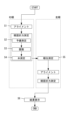
図1は、眼屈折力測定装置1の外観図である。眼屈折力測定装置1は、基台2、顔支持部3、駆動部4、表示部75、操作部76、および測定部100、等を備える。顔支持部3は、基台2に固定され、被検者の顔を支持する。駆動部4は、基台2に対して測定部100をXYZ方向に駆動させる。表示部75は、各種の情報(例えば、被検者の顔画像、被検眼の前眼部画像、被検眼の測定結果、等)を表示する。操作部76は、各種の設定を行う。本実施例では、タッチパネル付きの表示部75が操作部76を兼用する。測定部100は、後述の光学系を収納する。 <Device configuration>
FIG. 1 is an external view of an eye refractivepower measuring device 1. FIG. The eye refractive power measurement apparatus 1 includes a base 2, a face support section 3, a drive section 4, a display section 75, an operation section 76, a measurement section 100, and the like. The face support part 3 is fixed to the base 2 and supports the subject's face. The drive unit 4 drives the measurement unit 100 in the XYZ directions with respect to the base 2 . The display unit 75 displays various types of information (for example, the face image of the subject, the anterior segment image of the subject's eye, the measurement results of the subject's eye, etc.). The operation unit 76 performs various settings. In this embodiment, a display unit 75 with a touch panel also serves as the operation unit 76 . The measurement unit 100 accommodates an optical system, which will be described later.
図1は、眼屈折力測定装置1の外観図である。眼屈折力測定装置1は、基台2、顔支持部3、駆動部4、表示部75、操作部76、および測定部100、等を備える。顔支持部3は、基台2に固定され、被検者の顔を支持する。駆動部4は、基台2に対して測定部100をXYZ方向に駆動させる。表示部75は、各種の情報(例えば、被検者の顔画像、被検眼の前眼部画像、被検眼の測定結果、等)を表示する。操作部76は、各種の設定を行う。本実施例では、タッチパネル付きの表示部75が操作部76を兼用する。測定部100は、後述の光学系を収納する。 <Device configuration>
FIG. 1 is an external view of an eye refractive
図2は、眼屈折力測定装置1の光学系及び制御系の概略構成図である。測定部100は、測定光学系200、固視標光学系300、指標投影光学系400、観察光学系500、顔照明光学系600、顔撮影光学系700、等を備える。測定光学系200は、被検眼Eの眼屈折力(例えば、球面度数、円柱度数、乱視軸角度、等)を他覚的に測定する。固視標光学系300は、被検眼Eに固視標を呈示する。指標投影光学系400は、被検眼Eにアライメント指標を投影する。観察光学系500は、被検眼Eの前眼部を撮像する。顔照明光学系600は、被検者の顔を照明する。顔撮影光学系700は、被検者の顔を撮影する。
なお、被検眼Eの眼前にはビームスプリッタ230が配置される。ビームスプリッタ230は、被検眼Eへ固視標光学系300からの測定光束を導く。また、ビームスプリッタ230は、被検眼Eの前眼部からの反射光束を観察光学系500へと導く。 FIG. 2 is a schematic configuration diagram of the optical system and control system of the eye refractivepower measuring apparatus 1. As shown in FIG. The measurement unit 100 includes a measurement optical system 200, a fixation target optical system 300, an index projection optical system 400, an observation optical system 500, a face illumination optical system 600, a face photographing optical system 700, and the like. The measurement optical system 200 objectively measures the eye refractive power of the subject's eye E (for example, spherical power, cylindrical power, astigmatism axis angle, etc.). The fixation target optical system 300 presents the eye E to be examined with a fixation target. The index projection optical system 400 projects an alignment index onto the eye E to be examined. The observation optical system 500 images the anterior segment of the eye E to be examined. A face illumination optical system 600 illuminates the subject's face. A face photographing optical system 700 photographs the subject's face.
Abeam splitter 230 is arranged in front of the eye E to be examined. The beam splitter 230 guides the measurement light flux from the fixation target optical system 300 to the eye E to be examined. The beam splitter 230 also guides the reflected light flux from the anterior segment of the eye E to be examined to the observation optical system 500 .
なお、被検眼Eの眼前にはビームスプリッタ230が配置される。ビームスプリッタ230は、被検眼Eへ固視標光学系300からの測定光束を導く。また、ビームスプリッタ230は、被検眼Eの前眼部からの反射光束を観察光学系500へと導く。 FIG. 2 is a schematic configuration diagram of the optical system and control system of the eye refractive
A
<測定光学系>
測定光学系200は、投光光学系210と、受光光学系220と、をビームスプリッタ230の透過方向に有している。投光光学系210は、光源211、リレーレンズ212、ホールミラー213、プリズム214、対物レンズ216、等を備える。光源211は、眼底と光学的に共役な位置関係である。ホールミラー213の開口は、瞳孔と光学的に共役な位置関係である。プリズム214は、瞳孔と光学的に共役な位置から外れた位置に配置され、プリズム214を通過する光束を光軸N1に対して偏心させる。プリズム214は、駆動部215によって、光軸N1を中心に回転駆動される。なお、プリズム214に代えて、光軸N1上に平行平面板を斜めに配置してもよい。 <Measurement optical system>
The measurementoptical system 200 has a light projecting optical system 210 and a light receiving optical system 220 in the transmission direction of the beam splitter 230 . The projection optical system 210 includes a light source 211, a relay lens 212, a hole mirror 213, a prism 214, an objective lens 216, and the like. The light source 211 is in an optically conjugate positional relationship with the fundus. The aperture of the hole mirror 213 is in an optically conjugate positional relationship with the pupil. The prism 214 is arranged at a position out of optical conjugate with the pupil, and decenters the light beam passing through the prism 214 with respect to the optical axis N1. The prism 214 is rotationally driven around the optical axis N1 by the driving section 215 . Instead of the prism 214, a plane-parallel plate may be obliquely arranged on the optical axis N1.
測定光学系200は、投光光学系210と、受光光学系220と、をビームスプリッタ230の透過方向に有している。投光光学系210は、光源211、リレーレンズ212、ホールミラー213、プリズム214、対物レンズ216、等を備える。光源211は、眼底と光学的に共役な位置関係である。ホールミラー213の開口は、瞳孔と光学的に共役な位置関係である。プリズム214は、瞳孔と光学的に共役な位置から外れた位置に配置され、プリズム214を通過する光束を光軸N1に対して偏心させる。プリズム214は、駆動部215によって、光軸N1を中心に回転駆動される。なお、プリズム214に代えて、光軸N1上に平行平面板を斜めに配置してもよい。 <Measurement optical system>
The measurement
本実施例において、光源211は、被検者が眩しさを感じにくい赤外域の光を発することが望ましい。但し、必ずしもこれに限られるものではない。また、本実施例において、光源211は、被検眼Eの徹照像を撮影するための照明光源として用いられてもよい。すなわち、光源211から出射された光束(照明光)の眼底反射光によって、被検眼Eの瞳孔内が照明されてもよい。
In this embodiment, the light source 211 desirably emits light in the infrared region that is less likely to be perceived as glare by the subject. However, it is not necessarily limited to this. Also, in this embodiment, the light source 211 may be used as an illumination light source for photographing a retroillumination image of the eye E to be examined. That is, the inside of the pupil of the subject's eye E may be illuminated by the fundus reflected light of the luminous flux (illumination light) emitted from the light source 211 .
受光光学系220は、対物レンズ216、プリズム214、ホールミラー213、リレーレンズ221、全反射ミラー222、受光絞り223、コリメータレンズ224、リングレンズ225、撮像素子226、等を備える。受光光学系220において、対物レンズ216、プリズム214、及びホールミラー213は、投光光学系210と共用される。受光絞り223は、眼底と光学的に共役な位置関係である。リングレンズ225は、瞳孔と光学的に共役な位置関係である。撮像素子226は、眼底と光学的に共役な位置関係である。
The light receiving optical system 220 includes an objective lens 216, a prism 214, a hall mirror 213, a relay lens 221, a total reflection mirror 222, a light receiving diaphragm 223, a collimator lens 224, a ring lens 225, an imaging device 226, and the like. In the light receiving optical system 220 , the objective lens 216 , the prism 214 and the hole mirror 213 are shared with the light projecting optical system 210 . The light receiving diaphragm 223 is in a positional relationship optically conjugate with the fundus. The ring lens 225 is in an optically conjugate positional relationship with the pupil. The imaging device 226 is in a positional relationship optically conjugate with the fundus.
このような測定光学系200の構成において、光源211から出射された測定光束は、リレーレンズ212、ホールミラー213、プリズム214、対物レンズ216、及びビームスプリッタ230を経て、眼底にスポット状の光束として投影される。これによって、眼底上に点光源像が形成される。このとき、プリズム214は光軸N1周りに回転され、ホールミラー213の開口における瞳投影像(瞳上での投影光束)が、高速に偏心回転される。眼底にて測定光束が反射された反射光束は、ビームスプリッタ230、対物レンズ216、及びプリズム214を介して、ホールミラー213に反射される。反射光束は、さらに、リレーレンズ221を通過して全反射ミラー222に反射され、受光絞り223の位置に集光し、コリメータレンズ224とリングレンズ225によって、リング状の像(リング像)として撮像素子226に結像する。撮像素子226からの出力信号は、制御部70に入力され、眼屈折力が演算される。
In the configuration of the measurement optical system 200 as described above, the measurement light flux emitted from the light source 211 passes through the relay lens 212, the hole mirror 213, the prism 214, the objective lens 216, and the beam splitter 230, and forms a spot light flux on the fundus. projected. As a result, a point light source image is formed on the fundus. At this time, the prism 214 is rotated around the optical axis N1, and the pupil projected image (projected light flux on the pupil) at the aperture of the hole mirror 213 is eccentrically rotated at high speed. The reflected light flux, which is the measurement light flux reflected by the fundus, is reflected by the hole mirror 213 via the beam splitter 230 , the objective lens 216 and the prism 214 . The reflected light beam further passes through the relay lens 221 and is reflected by the total reflection mirror 222, condensed at the position of the light receiving aperture 223, and picked up as a ring image by the collimator lens 224 and the ring lens 225. It is imaged onto element 226 . An output signal from the imaging element 226 is input to the control section 70, and the eye refractive power is calculated.
なお、測定光学系200は、被検眼Eの眼底に測定光束を投影する投光光学系と、眼底により反射された測定光束の反射光束を受光する受光光学系と、を有する光学系であればよく、本実施例とは異なる光学系としてもよい。例えば、測定光学系200は、眼底にスポット指標を投影し、シャックハルトマンセンサを用いて、眼底におけるスポット指標の反射光束を検出する光学系であってもよい。また、例えば、測定光学系200は、被検眼Eにスリットを投影する位相差方式の光学系であってもよい。
Note that the measurement optical system 200 is an optical system having a light projecting optical system that projects the measurement light flux onto the fundus of the subject's eye E and a light reception optical system that receives the reflected light flux of the measurement light flux reflected by the fundus. Well, an optical system different from that of this embodiment may be used. For example, the measurement optical system 200 may be an optical system that projects a spot index onto the fundus of the eye and uses a Shack-Hartmann sensor to detect the reflected light flux of the spot index on the fundus of the eye. Further, for example, the measurement optical system 200 may be a phase-difference optical system that projects a slit onto the eye E to be examined.
<固視標光学系>
固視標光学系300は、光源301、固視標板302、投光レンズ303、全反射ミラー304、ハーフミラー305、対物レンズ306、等をビームスプリッタ230の反射方向に有している。光源301により固視標板302を照明することで、被検眼Eに固視標が呈示される。固視標板302は、被検眼Eを固視させ、その眼屈折力を測定する際に用いられる。駆動部307は、固視標板302を光軸N2方向へ移動させることで、被検眼Eに対する固視標の呈示位置を移動させることができる。また、駆動部307は、光源301及び固視標板302を光軸N2方向へ移動させることで、被検眼Eに雲霧をかけることができる。 <Fixation target optical system>
The fixation targetoptical system 300 has a light source 301 , a fixation target plate 302 , a projection lens 303 , a total reflection mirror 304 , a half mirror 305 , an objective lens 306 , etc. in the reflection direction of the beam splitter 230 . A fixation target is presented to the subject's eye E by illuminating the fixation target plate 302 with the light source 301 . The fixation target plate 302 is used when the subject's eye E is fixed and its eye refractive power is measured. The drive unit 307 can move the presentation position of the fixation target with respect to the eye E by moving the fixation target plate 302 in the direction of the optical axis N2. Further, the drive unit 307 can fog the eye E by moving the light source 301 and the fixation target plate 302 in the direction of the optical axis N2.
固視標光学系300は、光源301、固視標板302、投光レンズ303、全反射ミラー304、ハーフミラー305、対物レンズ306、等をビームスプリッタ230の反射方向に有している。光源301により固視標板302を照明することで、被検眼Eに固視標が呈示される。固視標板302は、被検眼Eを固視させ、その眼屈折力を測定する際に用いられる。駆動部307は、固視標板302を光軸N2方向へ移動させることで、被検眼Eに対する固視標の呈示位置を移動させることができる。また、駆動部307は、光源301及び固視標板302を光軸N2方向へ移動させることで、被検眼Eに雲霧をかけることができる。 <Fixation target optical system>
The fixation target
なお、駆動部307は、固視標板302に対して投光レンズ303を光軸N2方向へ移動させることで、固視標の呈示位置を変更してもよい。従って、駆動部307は、固視標板302に対して投光レンズ303を光軸N2方向へ移動させることで、被検眼Eに雲霧を付加してもよい。
The driving unit 307 may change the presentation position of the fixation target by moving the projection lens 303 with respect to the fixation target plate 302 in the direction of the optical axis N2. Therefore, the driving unit 307 may add fog to the subject's eye E by moving the projection lens 303 with respect to the fixation target plate 302 in the direction of the optical axis N2.
<指標投影光学系>
指標投影光学系400は、第1指標投影光学系と、第2指標投影光学系と、を備える。第1指標投影光学系は、被検眼Eの角膜に無限遠のアライメント指標を投影する。第2指標投影光学系は、被検眼Eの角膜に有限遠のアライメント指標を投影する。 <Target projection optical system>
The index projectionoptical system 400 includes a first index projection optical system and a second index projection optical system. The first index projection optical system projects an infinite alignment index onto the cornea of the eye E to be examined. The second index projection optical system projects a finite alignment index onto the cornea of the eye E to be examined.
指標投影光学系400は、第1指標投影光学系と、第2指標投影光学系と、を備える。第1指標投影光学系は、被検眼Eの角膜に無限遠のアライメント指標を投影する。第2指標投影光学系は、被検眼Eの角膜に有限遠のアライメント指標を投影する。 <Target projection optical system>
The index projection
第1指標投影光学系は、点光源401a及び401b、コリメータレンズ402a及び402b、等を有する。点光源401a及び401bは、近赤外光を発する。コリメータレンズ402a及び402bは、点光源が発した光束を平行光束(略平行光束)にする。例えば、これらの点光源及びコリメータレンズは、光軸N1を基準とした同心円上に45度間隔で、かつ、光軸N1を通る垂直平面を挟んで左右対称となるように、複数個が配置される。
The first target projection optical system has point light sources 401a and 401b, collimator lenses 402a and 402b, and the like. The point light sources 401a and 401b emit near-infrared light. The collimator lenses 402a and 402b collimate the luminous flux emitted by the point light source into a parallel luminous flux (substantially parallel luminous flux). For example, a plurality of these point light sources and collimator lenses are arranged on a concentric circle with respect to the optical axis N1 at intervals of 45 degrees and symmetrical with respect to a vertical plane passing through the optical axis N1. be.
第2指標投影光学系は、点光源403a及び403bを有する。点光源403a及び403bは、近赤外光を発する。例えば、これらの点光源は、第1指標投影光学系の点光源よりも狭い角度で、かつ、光軸を通る垂直平面を挟んで左右対称となるように、複数個が配置される。第2指標投影光学系は、被検眼Eの前眼部を照明する前眼部照明、被検眼Eの角膜形状を測定するための指標、等としても用いることができる。
The second target projection optical system has point light sources 403a and 403b. The point light sources 403a and 403b emit near-infrared light. For example, a plurality of these point light sources are arranged so as to have a narrower angle than the point light sources of the first target projection optical system and to be bilaterally symmetric across a vertical plane passing through the optical axis. The second target projection optical system can also be used as an anterior segment illumination for illuminating the anterior segment of the eye E to be inspected, an index for measuring the shape of the cornea of the eye E to be inspected, and the like.
なお、指標投影光学系400は、点状の指標、リング状の指標(いわゆるマイヤーリング等)、ライン状の指標、等の少なくともいずれかを投影するように構成されてもよい。
Note that the index projection optical system 400 may be configured to project at least one of a point-like index, a ring-like index (so-called Meyer ring, etc.), a line-like index, and the like.
<観察光学系>
観察光学系500は、対物レンズ306、ハーフミラー305、撮像レンズ501、撮像素子502、等をビームスプリッタ230の反射方向に有している。撮像素子502は、被検眼Eの前眼部と光学的に共役な位置関係であり、前眼部からの反射光束を受光する。これによって、被検眼Eの前眼部画像(前眼部の正面画像)が撮像される。前眼部画像の一種である徹照像が撮影されてもよい。撮像素子502からの出力信号は、制御部70及び表示部75に入力される。観察光学系500は、被検眼Eの角膜に形成されたアライメント指標像を検出する光学系を兼ね、制御部70によって、アライメント指標像の位置が検出される。 <Observation optical system>
The observationoptical system 500 has an objective lens 306 , a half mirror 305 , an imaging lens 501 , an imaging element 502 , etc. in the reflection direction of the beam splitter 230 . The imaging device 502 is in a positional relationship optically conjugate with the anterior segment of the subject's eye E, and receives reflected light beams from the anterior segment. As a result, an anterior segment image of the subject's eye E (a front image of the anterior segment) is captured. A transillumination image, which is a type of anterior segment image, may be captured. An output signal from the imaging element 502 is input to the control section 70 and the display section 75 . The observation optical system 500 also serves as an optical system for detecting an alignment index image formed on the cornea of the subject's eye E, and the controller 70 detects the position of the alignment index image.
観察光学系500は、対物レンズ306、ハーフミラー305、撮像レンズ501、撮像素子502、等をビームスプリッタ230の反射方向に有している。撮像素子502は、被検眼Eの前眼部と光学的に共役な位置関係であり、前眼部からの反射光束を受光する。これによって、被検眼Eの前眼部画像(前眼部の正面画像)が撮像される。前眼部画像の一種である徹照像が撮影されてもよい。撮像素子502からの出力信号は、制御部70及び表示部75に入力される。観察光学系500は、被検眼Eの角膜に形成されたアライメント指標像を検出する光学系を兼ね、制御部70によって、アライメント指標像の位置が検出される。 <Observation optical system>
The observation
<顔照明光学系>
顔照明光学系600は、照明光源601、等を備える。照明光源601は、指向性の低い光源であってもよい。また、照明光源601は、赤外光を発する光源であってもよい。なお、顔照明光学系600は、被検者の顔を照明する顔照明の他、被検眼Eの眼位を測定するための指標としても用いることができる。つまり、顔照明光学系600は、被検眼Eの角膜に眼位測定用指標を投影する。 <Face illumination optical system>
The face illuminationoptical system 600 includes an illumination light source 601 and the like. The illumination light source 601 may be a light source with low directivity. Also, the illumination light source 601 may be a light source that emits infrared light. The face illumination optical system 600 can be used not only as a face illumination for illuminating the subject's face, but also as an index for measuring the eye position of the eye E to be examined. That is, the face illumination optical system 600 projects the index for eye position measurement onto the cornea of the eye E to be examined.
顔照明光学系600は、照明光源601、等を備える。照明光源601は、指向性の低い光源であってもよい。また、照明光源601は、赤外光を発する光源であってもよい。なお、顔照明光学系600は、被検者の顔を照明する顔照明の他、被検眼Eの眼位を測定するための指標としても用いることができる。つまり、顔照明光学系600は、被検眼Eの角膜に眼位測定用指標を投影する。 <Face illumination optical system>
The face illumination
<顔撮影光学系>
顔撮影光学系700は、撮像レンズ701、撮像素子702、等を備える。撮像素子702は、顔からの反射光束を受光する。これによって、被検眼Eの左眼及び右眼の少なくとも一方を含む顔画像が撮像される。撮像素子702からの出力信号は、制御部70及び表示部75に入力される。顔撮影光学系700は、被検眼Eの角膜に形成された眼位測定用指標像を検出する光学系を兼ね、制御部70によって、眼位測定用指標像の位置が検出される。 <Face shooting optical system>
The face imagingoptical system 700 includes an imaging lens 701, an imaging element 702, and the like. The imaging element 702 receives the reflected light flux from the face. As a result, a face image including at least one of the left eye and the right eye of the subject's eye E is captured. An output signal from the imaging element 702 is input to the control section 70 and the display section 75 . The face photographing optical system 700 also serves as an optical system for detecting the index image for eye position measurement formed on the cornea of the subject's eye E, and the control unit 70 detects the position of the index image for eye position measurement.
顔撮影光学系700は、撮像レンズ701、撮像素子702、等を備える。撮像素子702は、顔からの反射光束を受光する。これによって、被検眼Eの左眼及び右眼の少なくとも一方を含む顔画像が撮像される。撮像素子702からの出力信号は、制御部70及び表示部75に入力される。顔撮影光学系700は、被検眼Eの角膜に形成された眼位測定用指標像を検出する光学系を兼ね、制御部70によって、眼位測定用指標像の位置が検出される。 <Face shooting optical system>
The face imaging
本実施例では、顔撮影光学系700が撮像レンズ701として広角レンズを備えることで、被検者の顔を広い画角で撮影できる。例えば、画角は87°以上であってもよい。これによって、被検者の両眼が顔画像に含まれやすくなる。また、本実施例では、顔撮影光学系700の光路に可視光カットフィルタを配置してもよい。これによって、被検者の顔を撮影する際、可視光によるノイズ光が制限される。ここで、顔からの赤外光の反射光は撮像素子702に検出されるが、この場合、赤外光によるノイズ光が入射する可能性がある。このため、撮像素子702のゲイン等を調整し、赤外光のノイズの影響を軽減させてもよい。
In this embodiment, the face photographing optical system 700 includes a wide-angle lens as the imaging lens 701, so that the subject's face can be photographed with a wide angle of view. For example, the angle of view may be 87° or more. This makes it easier for the subject's eyes to be included in the face image. Also, in this embodiment, a visible light cut filter may be arranged in the optical path of the face imaging optical system 700 . This limits visible light noise when photographing the subject's face. Here, the reflected infrared light from the face is detected by the imaging element 702, but in this case, noise light due to the infrared light may enter. Therefore, the gain or the like of the image sensor 702 may be adjusted to reduce the influence of infrared light noise.
<制御部>
制御部70は、CPU(プロセッサ)、RAM、ROM、等を備える。CPUは、眼屈折力測定装置1における各部の駆動を制御する。RAMは、各種の情報を一時的に記憶する。ROMには、CPUが実行する各種プログラム等が記憶されている。なお、制御部70は、複数の制御部(つまり、複数のプロセッサ)によって構成されてもよい。 <Control section>
Thecontrol unit 70 includes a CPU (processor), RAM, ROM, and the like. The CPU controls driving of each part in the eye refractive power measuring device 1 . The RAM temporarily stores various information. Various programs executed by the CPU are stored in the ROM. Note that the controller 70 may be configured by a plurality of controllers (that is, a plurality of processors).
制御部70は、CPU(プロセッサ)、RAM、ROM、等を備える。CPUは、眼屈折力測定装置1における各部の駆動を制御する。RAMは、各種の情報を一時的に記憶する。ROMには、CPUが実行する各種プログラム等が記憶されている。なお、制御部70は、複数の制御部(つまり、複数のプロセッサ)によって構成されてもよい。 <Control section>
The
制御部70には、駆動部4、表示部75(操作部76)、不揮発性メモリ72(以下、メモリ72)、等が電気的に接続される。また、制御部70には、測定部100が備える各光源、各撮像素子、各駆動部、等が電気的に接続される。
The control unit 70 is electrically connected to the drive unit 4, the display unit 75 (operation unit 76), the nonvolatile memory 72 (hereinafter referred to as the memory 72), and the like. In addition, each light source, each imaging element, each drive section, and the like provided in the measurement section 100 are electrically connected to the control section 70 .
メモリ72は、電源の供給が遮断されても記憶内容を保持できる非一過性の記憶媒体である。例えば、メモリ72としては、ハードディスクドライブ、フラッシュROM、USBメモリ、等を用いることができる。メモリ72には、被検眼Eの測定結果(一例として、眼屈折力、眼位情報、等)を記憶してもよい。
The memory 72 is a non-transitory storage medium that can retain stored content even when the power supply is interrupted. For example, the memory 72 can be a hard disk drive, flash ROM, USB memory, or the like. The memory 72 may store the measurement results of the subject's eye E (eg, eye refractive power, eye position information, etc.).
<制御動作>
眼屈折力測定装置1の制御動作を、図3のフローチャート図に沿って説明する。本実施例では、被検眼Eと測定部100とのアライメントが、全自動(フルオート)で実行される。また、被検眼Eに対する眼屈折力の測定の流れの中で、被検眼Eの眼位情報(ここでは、斜位に関する情報)が取得される。 <Control action>
The control operation of the eye refractivepower measuring device 1 will be described with reference to the flow chart of FIG. In this embodiment, the alignment between the subject's eye E and the measurement unit 100 is fully automated. In addition, eye position information (here, information on the oblique position) of the eye E to be inspected is acquired in the course of measuring the eye refractive power of the eye E to be inspected.
眼屈折力測定装置1の制御動作を、図3のフローチャート図に沿って説明する。本実施例では、被検眼Eと測定部100とのアライメントが、全自動(フルオート)で実行される。また、被検眼Eに対する眼屈折力の測定の流れの中で、被検眼Eの眼位情報(ここでは、斜位に関する情報)が取得される。 <Control action>
The control operation of the eye refractive
<アライメント>
ステップS1では、被検者の右眼(測定眼)に対する測定部100のフルオートアライメントが行われる。検者は被検者に、顔を顔支持部3で固定し、固視標を観察するように指示する。制御部70は、顔照明光学系600の照明光源601と、固視標光学系300の光源301と、指標投影光学系400の点光源と、を点灯させる。 <Alignment>
In step S1, full auto alignment of themeasurement unit 100 with respect to the right eye (measurement eye) of the subject is performed. The examiner instructs the subject to fix the face with the face support 3 and observe the fixation target. The control unit 70 turns on the illumination light source 601 of the face illumination optical system 600 , the light source 301 of the fixation target optical system 300 , and the point light source of the index projection optical system 400 .
ステップS1では、被検者の右眼(測定眼)に対する測定部100のフルオートアライメントが行われる。検者は被検者に、顔を顔支持部3で固定し、固視標を観察するように指示する。制御部70は、顔照明光学系600の照明光源601と、固視標光学系300の光源301と、指標投影光学系400の点光源と、を点灯させる。 <Alignment>
In step S1, full auto alignment of the
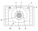
図4Aは、顔画像800の全体像である。図4Bは、右眼の拡大図である。図4Cは、左眼の拡大図である。まず、右眼に対する測定部100の粗アライメントが行われる。被検者の顔は、顔照明光学系600の照明光源601によって照明され、これによって、右眼と左眼に眼位測定用指標像Rが投影される。また、被検者の顔は、顔撮影光学系700の撮像素子702によって撮像され、顔画像800が表示部75に表示される。制御部70は、顔画像から右眼と左眼を検出して、右眼と左眼の3次元座標を推定し、右眼の3次元座標に基づいて測定部100をXYZ方向へと移動させる。例えば、これによって、右眼に測定部100がおおよそアライメントされる。
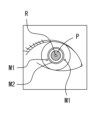
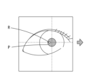
FIG. 4A is an overall image of the face image 800. FIG. FIG. 4B is an enlarged view of the right eye. FIG. 4C is an enlarged view of the left eye. First, coarse alignment of the measurement unit 100 with respect to the right eye is performed. The subject's face is illuminated by the illumination light source 601 of the face illumination optical system 600, thereby projecting the index image R for eye position measurement to the right and left eyes. The subject's face is imaged by the imaging device 702 of the face imaging optical system 700 and a face image 800 is displayed on the display unit 75 . The control unit 70 detects the right eye and the left eye from the face image, estimates the three-dimensional coordinates of the right eye and the left eye, and moves the measurement unit 100 in the XYZ directions based on the three-dimensional coordinates of the right eye. . For example, this roughly aligns the measurement unit 100 with the right eye.
図5は、右眼の前眼部画像900の一例である。次に、右眼に対する測定部100の微アライメントが行われる。右眼に測定部100が近づくと、右眼は、固視標光学系300の光源301に照明された固視標板302(すなわち、固視標)を視認できるようになる。また、右眼の角膜に指標投影光学系400によるアライメント指標像(無限遠のアライメント指標像M1と有限遠のアライメント指標像M2)が投影される。また、右眼の前眼部が観察光学系500の撮像素子502によって撮影され、その前眼部画像900が表示部75に表示される。制御部70は、前眼部画像900からアライメント指標像を検出し、これらの位置関係に基づいて測定部100をXYZ方向へと移動させる。例えば、これによって、右眼と測定部100とが所定の作動距離となり、微アライメントが完了される。
FIG. 5 is an example of an anterior segment image 900 of the right eye. Next, fine alignment of the measurement unit 100 with respect to the right eye is performed. When the measurement unit 100 approaches the right eye, the right eye can visually recognize the fixation target plate 302 illuminated by the light source 301 of the fixation target optical system 300 (that is, the fixation target). Alignment index images (infinite distance alignment index image M1 and finite distance alignment index image M2) are projected by the index projection optical system 400 onto the cornea of the right eye. Also, the anterior segment of the right eye is imaged by the imaging device 502 of the observation optical system 500 , and the anterior segment image 900 is displayed on the display section 75 . The control unit 70 detects alignment index images from the anterior segment image 900, and moves the measurement unit 100 in the XYZ directions based on the positional relationship between them. For example, this brings the right eye and the measurement unit 100 into a predetermined working distance, completing the fine alignment.
もちろん、本実施例では顔画像800及び前眼部画像900を用いたフルオートアライメントを例に挙げたが、検者が操作部76を操作して手動でアライメントを実施することも可能である。なお、本実施例の操作部76はタッチパネル付きの表示部75と兼用されているが、ジョイスティック等であってもよい。
Of course, in the present embodiment, the full-automatic alignment using the face image 800 and the anterior segment image 900 is taken as an example, but it is also possible for the examiner to operate the operation unit 76 to manually perform alignment. Although the operation unit 76 in this embodiment is also used as the display unit 75 with a touch panel, it may be a joystick or the like.
<眼屈折力と眼位の測定>
ステップS1にてアライメントが完了すると、右眼の眼屈折力と、左眼の眼位の測定と、が開始される。 <Measurement of eye refractive power and eye position>
When the alignment is completed in step S1, measurement of the eye refractive power of the right eye and the eye position of the left eye is started.
ステップS1にてアライメントが完了すると、右眼の眼屈折力と、左眼の眼位の測定と、が開始される。 <Measurement of eye refractive power and eye position>
When the alignment is completed in step S1, measurement of the eye refractive power of the right eye and the eye position of the left eye is started.
<眼屈折力の予備測定>
ステップS2では、右眼の眼屈折力の予備測定が行われる。制御部70は、右眼に対して光学的に十分な遠方の初期位置に固視標板302を配置させる。例えば、右眼が正視眼であれば、右眼の焦点が固視標に合い、固視標がはっきりと観察される。一方、例えば、右眼が近視眼または遠視眼であると、右眼の焦点が固視標に合わず、固視標がぼやけて観察される。制御部70は、測定光学系200の光源211から測定光束を照射させ、測定光束の反射光束をリング像として撮像素子226に撮像させる。撮像素子226に撮影された予備測定画像は、メモリ72に記憶される。 <Preliminary measurement of eye refractive power>
At step S2, a preliminary measurement of the ocular refractive power of the right eye is performed. Thecontrol unit 70 places the fixation target plate 302 at an initial position optically sufficiently distant from the right eye. For example, if the right eye is an emmetropic eye, the focus of the right eye is on the fixation target and the fixation target is clearly observed. On the other hand, for example, if the right eye is myopic or hyperopic, the focus of the right eye is not on the fixation target, and the fixation target is observed blurry. The control unit 70 causes the light source 211 of the measurement optical system 200 to irradiate the measurement light flux, and causes the imaging element 226 to image the reflected light flux of the measurement light flux as a ring image. The preliminary measurement image captured by the imaging device 226 is stored in the memory 72 .
ステップS2では、右眼の眼屈折力の予備測定が行われる。制御部70は、右眼に対して光学的に十分な遠方の初期位置に固視標板302を配置させる。例えば、右眼が正視眼であれば、右眼の焦点が固視標に合い、固視標がはっきりと観察される。一方、例えば、右眼が近視眼または遠視眼であると、右眼の焦点が固視標に合わず、固視標がぼやけて観察される。制御部70は、測定光学系200の光源211から測定光束を照射させ、測定光束の反射光束をリング像として撮像素子226に撮像させる。撮像素子226に撮影された予備測定画像は、メモリ72に記憶される。 <Preliminary measurement of eye refractive power>
At step S2, a preliminary measurement of the ocular refractive power of the right eye is performed. The
制御部70は、予備測定画像に基づいて、予備測定における眼屈折力を算出する。例えば、右眼が正視眼であれば、眼底からの反射光束はリングレンズ225に平行光束(略平行光束)として入射する。このため、リングレンズ225と同じ大きさのリング像が予備測定画像として得られる。一方、例えば、右眼が近視眼であると、球面度数に応じて縮小されたリング像が予備測定画像として得られる。また、例えば、右眼が遠視眼であると、球面度数に応じて拡大されたリング像が予備測定画像として得られる。なお、例えば、右眼が乱視眼であると、円柱度数に応じて楕円形状となり、乱視軸角度に応じて傾斜したリング像が予備測定画像として得られる。制御部70は、リング像を細線化し、各経線方向のリング像の位置に基づいて、各経線方向の眼屈折力を求める。また、制御部70は、これらの眼屈折力に対して所定の処理を行い、右眼の予備的な眼屈折力を取得する。
The control unit 70 calculates the eye refractive power in the preliminary measurement based on the preliminary measurement image. For example, if the right eye is an emmetropic eye, the reflected luminous flux from the fundus enters the ring lens 225 as a parallel luminous flux (substantially parallel luminous flux). Therefore, a ring image having the same size as the ring lens 225 is obtained as a preliminary measurement image. On the other hand, for example, if the right eye is myopic, a ring image reduced according to the spherical power is obtained as the preliminary measurement image. Further, for example, if the right eye is a hyperopic eye, a ring image magnified according to the spherical power is obtained as the preliminary measurement image. For example, if the right eye is an astigmatic eye, a ring image that has an elliptical shape according to the cylindrical power and is tilted according to the astigmatic axis angle is obtained as a preliminary measurement image. The control unit 70 thins the ring image, and obtains the eye refractive power in each meridian direction based on the position of the ring image in each meridian direction. In addition, the control unit 70 performs predetermined processing on these eye refractive powers to obtain a preliminary eye refractive power of the right eye.
<雲霧>
ステップS3では、右眼に対して雲霧が付加される。ステップS2の予備測定時の眼屈折力は、調節が働いた状態で測定された可能性がある。すなわち、水晶体の厚み(水晶体の屈折力)を変化させた状態で測定された可能性がある。このため、制御部70は、右眼に雲霧を掛け、右眼の調節を解除させる。 <Kumogiri>
In step S3, fog is added to the right eye. There is a possibility that the refractive power of the eye during the preliminary measurement in step S2 was measured in a state in which accommodation was in effect. That is, there is a possibility that the measurement was performed while changing the thickness of the lens (refractive power of the lens). Therefore, thecontrol unit 70 fogs the right eye and cancels the adjustment of the right eye.
ステップS3では、右眼に対して雲霧が付加される。ステップS2の予備測定時の眼屈折力は、調節が働いた状態で測定された可能性がある。すなわち、水晶体の厚み(水晶体の屈折力)を変化させた状態で測定された可能性がある。このため、制御部70は、右眼に雲霧を掛け、右眼の調節を解除させる。 <Kumogiri>
In step S3, fog is added to the right eye. There is a possibility that the refractive power of the eye during the preliminary measurement in step S2 was measured in a state in which accommodation was in effect. That is, there is a possibility that the measurement was performed while changing the thickness of the lens (refractive power of the lens). Therefore, the
制御部70は、右眼の予備測定時の眼屈折力に基づいて、右眼が固視標板302に焦点を合わせられる雲霧開始位置に固視標板302を移動させる。これによって、右眼は固視標をはっきりと観察できるようになる。続いて、制御部70は、所定の雲霧量に相当する雲霧完了位置まで固視標板302を移動させる。このとき、固視標板302は、雲霧開始位置から雲霧完了位置に向けて、右眼から光学的に遠ざかる(離れる)方向へ移動される。固視標板302が雲霧完了位置に到達すると、右眼に雲霧がかけられ、右眼の焦点が再び固視標板302に合わなくなる。右眼の眼屈折力は、予備測定時の眼屈折力から真値へと近づき、右眼の調節が解除される。
The control unit 70 moves the fixation target plate 302 to the fog start position where the right eye is focused on the fixation target plate 302 based on the eye refractive power of the right eye during preliminary measurement. This allows the right eye to see the fixation target clearly. Subsequently, the control unit 70 moves the fixation target plate 302 to the cloudy completion position corresponding to a predetermined amount of cloudy weather. At this time, the fixation target plate 302 is moved from the fogging start position toward the fogging end position in a direction optically moving away from the right eye. When the fixation target plate 302 reaches the clouding completion position, the right eye is fogged and the right eye is no longer focused on the fixation target plate 302 . The eye refractive power of the right eye approaches the true value from the eye refractive power at the time of preliminary measurement, and the accommodation of the right eye is released.
<本測定>
ステップS4では、右眼に雲霧を付加した状態で、右眼の眼屈折力の本測定が行われる。制御部70は、所定のタイミング毎にリング像を本測定画像として撮像素子226に連続して撮影させ、これらをメモリ72に記憶させる。また、制御部70は、リング像の加算処理を行ってノイズ光を低減させるとともに、予備測定と同様の方法にて、右眼の本測定での眼屈折力を取得する。制御部70が取得した眼屈折力は、メモリ72に記憶される。 <Main measurement>
In step S4, the main measurement of the eye refractive power of the right eye is performed with fog added to the right eye. Thecontrol unit 70 causes the image sensor 226 to continuously photograph the ring images as the main measurement images at predetermined timings, and stores them in the memory 72 . Further, the control unit 70 performs addition processing of ring images to reduce noise light, and acquires the eye refractive power of the right eye in the main measurement by the same method as the preliminary measurement. The eye refractive power acquired by the control unit 70 is stored in the memory 72 .
ステップS4では、右眼に雲霧を付加した状態で、右眼の眼屈折力の本測定が行われる。制御部70は、所定のタイミング毎にリング像を本測定画像として撮像素子226に連続して撮影させ、これらをメモリ72に記憶させる。また、制御部70は、リング像の加算処理を行ってノイズ光を低減させるとともに、予備測定と同様の方法にて、右眼の本測定での眼屈折力を取得する。制御部70が取得した眼屈折力は、メモリ72に記憶される。 <Main measurement>
In step S4, the main measurement of the eye refractive power of the right eye is performed with fog added to the right eye. The
なお、制御部70は、このような右眼の本測定時の眼屈折力に基づいて、右眼が固視標板302に焦点を合わせられる測定完了位置に固視標板302を移動させる。これによって、右眼は再び固視標をはっきりと観察できるようになる。例えば、右眼に対する追加の眼屈折力の測定が必要な場合、測定完了位置に固視標板302が配置されていることによって、この測定完了位置を初期位置として、追加の測定をスムーズに開始できる。
Note that the control unit 70 moves the fixation target plate 302 to the measurement completion position where the right eye is focused on the fixation target plate 302 based on the eye refractive power of the right eye at the time of the main measurement. This allows the right eye to see the fixation target clearly again. For example, when additional eye refractive power measurement for the right eye is required, the fixation target plate 302 is arranged at the measurement completion position, so that the additional measurement can be started smoothly with this measurement completion position as the initial position. can.
<眼位測定>
ステップS5では、右眼の眼屈折力の測定と並行して、右眼に固視標を呈示している間に、左眼(非測定眼)の眼位測定が行われる。例えば、ステップS3で雲霧開始位置に固視標板302を移動させた際、または、ステップS4で右眼が焦点を合わせられる測定完了位置に固視標板302を移動させた際、等の少なくともいずれか(つまり、右眼が固視標をはっきりと観察した状態)のタイミングで、左眼の眼位測定が行われる。 <Eye position measurement>
In step S5, in parallel with the measurement of the eye refractive power of the right eye, eye position measurement of the left eye (non-measurement eye) is performed while the fixation target is presented to the right eye. For example, when thefixation target plate 302 is moved to the fog start position in step S3, or when the fixation target plate 302 is moved to the measurement completion position where the right eye is focused in step S4, at least At either timing (that is, a state in which the right eye clearly observes the fixation target), eye position measurement of the left eye is performed.
ステップS5では、右眼の眼屈折力の測定と並行して、右眼に固視標を呈示している間に、左眼(非測定眼)の眼位測定が行われる。例えば、ステップS3で雲霧開始位置に固視標板302を移動させた際、または、ステップS4で右眼が焦点を合わせられる測定完了位置に固視標板302を移動させた際、等の少なくともいずれか(つまり、右眼が固視標をはっきりと観察した状態)のタイミングで、左眼の眼位測定が行われる。 <Eye position measurement>
In step S5, in parallel with the measurement of the eye refractive power of the right eye, eye position measurement of the left eye (non-measurement eye) is performed while the fixation target is presented to the right eye. For example, when the
本実施例では、ステップS4にて左眼の眼位測定が行われる場合を例に挙げる。制御部70は、ステップS4で右眼が固視標をはっきりと観察している間に、顔画像800を撮像素子702に撮像させる。撮像素子702に撮影された顔画像800は、メモリ72に記憶される。
In this embodiment, the case where eye position measurement of the left eye is performed in step S4 will be taken as an example. The control unit 70 causes the imaging element 702 to capture the face image 800 while the right eye is clearly observing the fixation target in step S4. A face image 800 captured by the imaging device 702 is stored in the memory 72 .
ところで、被検眼Eが正位眼(非斜位眼)であると、右眼と左眼による両眼視の状態であっても、右眼で固視標を観察した片眼視の状態であっても、左眼の視線は移動しない。しかし、被検眼Eが斜位眼であると、両眼視の状態では左眼の視線は移動しないが、右眼による片眼視の状態では左眼の視線が移動する。つまり、被検眼Eが斜位眼であると、ステップS4で右眼が固視標を観察している間、左眼の瞳孔Pが斜位のある方向へと移動する。
By the way, if the eye to be examined E is an upright eye (a non-oblique eye), even in a state of binocular vision with the right and left eyes, monocular vision in which the fixation target is observed with the right eye. Even if there is, the line of sight of the left eye does not move. However, if the subject's eye E is an oblique eye, the line of sight of the left eye does not move in the state of binocular vision, but the line of sight of the left eye moves in the state of monocular vision with the right eye. That is, if the subject's eye E is an oblique eye, the pupil P of the left eye moves in the oblique direction while the right eye is observing the fixation target in step S4.
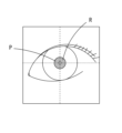
図6Aと図6Bは、いずれも顔画像800の左眼の拡大図であり、図6Aは正位眼を、図6Bは斜位眼を示している。例えば、正位眼では、左眼の瞳孔Pにおける中心位置と、眼位測定用指標像Rと、が所定の位置関係(一例としては、所定の距離と方向)となって現れる。一方、例えば、斜位眼では、左眼の瞳孔Pにおける中心位置と、眼位測定用指標像Rと、が所定の位置関係から変化する。一例として、被検者の外方向(耳側)へと左眼の瞳孔Pにおける中心位置が移動すると、これにともなって眼位測定用指標像Rが形成される位置が変化し、瞳孔Pの中心位置から眼位測定用指標像Rまでの距離、瞳孔Pの中心位置に対して眼位測定用指標像Rが現れる方向、等が変化する。
6A and 6B are both enlarged views of the left eye of the facial image 800, with FIG. 6A showing the upright eye and FIG. 6B showing the oblique eye. For example, in an upright eye, the central position of the pupil P of the left eye and the index image R for eye position measurement appear in a predetermined positional relationship (for example, a predetermined distance and direction). On the other hand, for example, in an oblique eye, the center position of the pupil P of the left eye and the index image R for eye position measurement change from a predetermined positional relationship. As an example, when the central position of the pupil P of the left eye moves outward (toward the ear) of the subject, the position where the index image R for eye position measurement is formed accordingly changes, and the position of the pupil P changes. The distance from the center position to the index image R for eye position measurement, the direction in which the index image R for eye position measurement appears with respect to the center position of the pupil P, and the like change.
被検眼Eが正位眼であり、右眼による片眼視かつ左眼の視線が移動しない状態において、左眼に眼位用測定指標像Rが形成される位置は、予測することが可能である。一例としては、被検眼毎に異なる右眼と左眼の瞳孔間距離を利用し、左眼と照明光源601の位置関係のずれを校正(キャリブレーション)することで、眼位用測定指標像Rが形成される位置を予測してもよい。もちろん、瞳孔間距離とは異なるパラメータ(一例として、角膜形状、等)を利用して校正されてもよいし、瞳孔間距離と瞳孔間距離とは異なるパラメータの双方を利用して校正されてもよい。これによって、左眼の瞳孔Pにおける中心位置に対し、眼位測定用指標像Rが形成される距離と方向が、基準として取得される。
It is possible to predict the position where the eye position measurement index image R is formed in the left eye when the subject's eye E is an upright eye, the right eye is monocular, and the left eye's line of sight does not move. be. As an example, the eye position measurement index image R may be predicted where is formed. Of course, it may be calibrated using a parameter different from the interpupillary distance (for example, corneal shape, etc.), or it may be calibrated using both the interpupillary distance and a parameter different from the interpupillary distance. good. As a result, the distance and direction in which the index image R for eye position measurement is formed with respect to the central position of the pupil P of the left eye are obtained as references.
なお、左眼と右眼の瞳孔間距離は、検者が操作部76を操作して手動で入力する構成でもよいし、本装置とは異なる装置を利用して測定した値を受信する構成でもよい。
The interpupillary distance between the left eye and the right eye may be manually input by the examiner by operating the operation unit 76, or may be configured to receive values measured using a device other than the present device. good.
制御部70は、顔画像800に基づいて、左眼の眼位情報を取得する。制御部70は、顔画像800を解析処理し、左眼の瞳孔Pにおける中心位置の座標と、眼位測定用指標像Rが形成された位置の座標と、を検出する。例えば、顔画像800の輝度の立ち上がりや立ち下がりから瞳孔を検出し、さらに、瞳孔の中心を計算することで、中心位置の座標を検出してもよい。また、例えば、顔画像800の輝度の立ち上がりや立ち下がりから、眼位測定用指標像Rが形成された位置の座標を検出してもよい。もちろん、顔画像800に右眼と左眼が映る位置はおおよそ特定されるため、解析処理の対象とする領域が予め設定されていてもよい。
The control unit 70 acquires the eye position information of the left eye based on the face image 800. The control unit 70 analyzes the face image 800 and detects the coordinates of the central position of the pupil P of the left eye and the coordinates of the position where the index image R for eye position measurement is formed. For example, the coordinates of the center position may be detected by detecting the pupil from the rise and fall of the luminance of the face image 800 and calculating the center of the pupil. Further, for example, the coordinates of the position where the index image R for eye position measurement is formed may be detected from the rise and fall of the brightness of the face image 800 . Of course, since the positions where the right eye and the left eye appear in the face image 800 are roughly specified, the area to be analyzed may be set in advance.
制御部70は、被検眼Eが正位眼である場合の、左眼の瞳孔Pにおける中心位置と眼位測定用指標像Rとの基準の位置関係と、顔画像800の解析処理にて検出された、左眼の瞳孔Pにおける中心位置と眼位測定用指標像Rとの実際の位置関係と、に基づいて、左眼における眼位の変化の有無を検出する。例えば、制御部70は、基準の位置関係に対する実際の位置関係において、その距離と方向の双方のずれが許容範囲内にあるときに、眼位の変化がないとしてもよい。言い換えると、被検眼Eを正位眼と判定してもよい。また、例えば、制御部70は、前述の距離と方向の少なくともいずれかのずれが許容範囲外にあるときに、眼位の変化があるとしてもよい。言い換えると、被検眼Eを斜位眼と判定してもよい。なお、被検眼Eが斜位眼である場合には、さらに斜位の方向と量を判定してもよい。制御部70が眼位情報として取得した斜位の有無、または、斜位の方向と量は、メモリ72に記憶される。
The control unit 70 detects the reference positional relationship between the center position of the pupil P of the left eye and the index image R for eye position measurement and the analysis processing of the face image 800 when the subject's eye E is an upright eye. Based on the actual positional relationship between the central position of the pupil P of the left eye and the index image R for eye position measurement, whether or not there is a change in the eye position of the left eye is detected. For example, the control unit 70 may determine that there is no change in eye position when both the distance and direction deviations are within the allowable range in the actual positional relationship with respect to the reference positional relationship. In other words, the subject's eye E may be determined to be an upright eye. Further, for example, the control unit 70 may determine that there is a change in eye position when at least one of the aforementioned distance and direction is out of the allowable range. In other words, the subject's eye E may be determined to be an oblique eye. When the subject's eye E is an oblique eye, the direction and amount of the oblique position may be further determined. The presence or absence of the oblique position, or the direction and amount of the oblique position acquired by the control unit 70 as the eye position information is stored in the memory 72 .
右眼の眼屈折力及び左眼の眼位の測定が完了すると、続いて、左眼の眼屈折力の測定が開始される。制御部70は、右眼と同様に、左眼に対して測定部100のアライメントを行い、予備測定、雲霧の付加、及び本測定を順に実行して、左眼の眼屈折力を取得する。
After the measurement of the eye refractive power of the right eye and the eye position of the left eye is completed, the measurement of the eye refractive power of the left eye is started. Similarly to the right eye, the control unit 70 aligns the measurement unit 100 with respect to the left eye, performs preliminary measurement, addition of fog, and main measurement in order to obtain the eye refractive power of the left eye.
ここで、被検眼Eが斜位眼であると、右眼による片眼視の状態では左眼の視線が移動し、左眼による片眼視の状態では右眼の視線が移動する傾向がみられる。このとき、右眼による片眼視の状態で左眼の視線が移動する方向と、左眼による片眼視の状態で右眼の視線が移動する方向と、は対称的な場合がある。例えば、外斜位であれば右眼または左眼は外方向(耳側)に偏位し、内斜位であれば右眼または左眼は内方向(鼻側)に偏位する。例えば、上下斜位であれば、右眼と左眼のいずれか一方が上方向(額側)に偏位し、他方が下方向に偏位する。つまり、ステップS5で左眼が正位眼と判定されれば、右眼も正位眼である可能性が高く、左眼が斜位眼と判定されれば、右眼も斜位眼である可能性が高い。このため、左眼の眼屈折力の測定では、必ずしも右眼の眼位の測定を並行して行う必要はなく、左眼の眼位情報に基づいて、右眼の眼位情報を取得してもよい。もちろん、左眼と同様に右眼の眼位を測定して、右眼の眼位情報を取得してもよい。
Here, when the subject's eye E is an oblique eye, there is a tendency that the line of sight of the left eye moves in the state of monocular vision with the right eye, and the line of sight of the right eye moves in the state of monocular vision with the left eye. be done. At this time, the direction in which the line of sight of the left eye moves in the state of monocular vision with the right eye may be symmetrical to the direction in which the line of sight of the right eye moves in the state of monocular vision with the left eye. For example, exotropia causes the right or left eye to deviate outward (early), and medial oblique causes the right or left eye to deviate inward (nasal). For example, in vertical oblique, one of the right eye and the left eye is deviated upward (toward the forehead), and the other is deviated downward. That is, if the left eye is determined to be the right eye in step S5, the right eye is likely to be the right eye as well, and if the left eye is determined to be the oblique eye, the right eye is also the oblique eye. Probability is high. Therefore, when measuring the eye refractive power of the left eye, it is not always necessary to measure the eye position of the right eye in parallel. good too. Of course, the eye position information of the right eye may be obtained by measuring the eye position of the right eye in the same manner as the left eye.
<結果表示>
ステップS6では、被検眼Eの眼屈折力と眼位情報が表示部75に表示される。例えば、制御部70は、左眼と右眼の球面度数、円柱度数、乱視軸角度、等の測定結果を表示部75に表示させる。また、例えば、制御部70は、左眼と右眼の斜位の有無、斜位の方向、斜位の量、等の眼位情報を表示部75に表示させる。 <Result display>
In step S<b>6 , the eye refractive power and eye position information of the eye E to be examined are displayed on thedisplay section 75 . For example, the control unit 70 causes the display unit 75 to display measurement results such as the spherical powers of the left and right eyes, the cylindrical powers, the astigmatism axis angle, and the like. Further, for example, the control unit 70 causes the display unit 75 to display eye position information such as the presence or absence of oblique position of the left eye and the right eye, the direction of the oblique position, the amount of the oblique position, and the like.
ステップS6では、被検眼Eの眼屈折力と眼位情報が表示部75に表示される。例えば、制御部70は、左眼と右眼の球面度数、円柱度数、乱視軸角度、等の測定結果を表示部75に表示させる。また、例えば、制御部70は、左眼と右眼の斜位の有無、斜位の方向、斜位の量、等の眼位情報を表示部75に表示させる。 <Result display>
In step S<b>6 , the eye refractive power and eye position information of the eye E to be examined are displayed on the
以上説明したように、本実施例の眼科装置は、被検者の顔画像を撮影し、この顔画像に基づいて、被検眼の眼位情報を取得する。これによって、眼科装置を用いて被検眼の光学特性を測定するとともに、被検眼の眼位情報を容易な構成で取得することができる。例えば、被検眼のアライメントのために顔画像を撮影する顔撮影手段を、被検眼の眼位情報を取得するための顔撮影手段として兼用し、眼位測定専用の撮影手段を設けることなく、装置を構成できる。
As described above, the ophthalmologic apparatus of this embodiment captures the face image of the subject and acquires the eye position information of the eye to be examined based on the face image. Accordingly, it is possible to measure the optical characteristics of the eye to be inspected using the ophthalmologic apparatus, and acquire eye position information of the eye to be inspected with a simple configuration. For example, the face photographing means for photographing the face image for the alignment of the eye to be inspected is also used as the face photographing means for acquiring the eye position information of the eye to be inspected. can be configured.
また、本実施例の眼科装置は、被検眼のうち、左眼及び右眼の一方である測定眼の光学特性を測定するとともに、測定眼に固視標を呈示している間に、左眼及び右眼の他方である非測定眼であって、測定眼とは異なる非測定眼を含む顔画像を撮影し、非測定眼の顔画像に基づいて眼位情報を取得する。例えば、測定眼の光学特性を測定するため、測定眼に固視標を呈示している間に、非測定眼を含む顔画像を撮影することで、別途、眼位測定のために顔画像を撮影する時間を設ける必要がなく、測定時間の延長、被検者の負担、等が軽減される。
In addition, the ophthalmologic apparatus of this embodiment measures the optical characteristics of the eye to be measured, which is one of the left eye and the right eye. A face image including a non-measurement eye that is the other of the right eye and the non-measurement eye that is different from the measurement eye is photographed, and eye position information is acquired based on the face image of the non-measurement eye. For example, in order to measure the optical characteristics of the eye to be measured, a facial image including the non-measuring eye is taken while a fixation target is presented to the eye to be measured. There is no need to provide time for photographing, and the extension of measurement time, the burden on the subject, and the like are reduced.
また、本実施例の眼科装置は、測定眼に固視標を呈示している間であって、測定眼が固視標を固視した状態で、非測定眼を含む顔画像を撮影する。これによって、例えば、被検眼が斜位眼である場合は、測定眼の視線が基準となる所定の方向(ここでは、正面方向)に向けられることで、非測定眼の眼位の変化を利用して、容易に眼位情報を取得することができる。また、測定眼の視線が所定の方向に向けられることで、非測定眼の眼位の変化に対するばらつきを抑えることができる。
Further, the ophthalmologic apparatus of this embodiment captures a face image including the non-measurement eye while the measurement eye is presenting the fixation target and the measurement eye is fixating the fixation target. As a result, for example, when the eye to be examined is an oblique eye, the line of sight of the eye to be measured is directed in a predetermined reference direction (here, the front direction), thereby utilizing the change in the eye position of the non-measured eye. Then, eye position information can be easily acquired. In addition, by directing the line of sight of the eye to be measured in a predetermined direction, it is possible to suppress variations in the eye position of the non-measurement eye.
また、本実施例の眼科装置は、被検眼に形成される角膜輝点像と、被検眼の瞳孔と、の位置関係に基づくキャリブレーションデータと、顔画像に含まれる角膜輝点像と瞳孔との位置関係と、に基づいて眼位情報を取得する。これによって、例えば、1枚の顔画像を撮影するのみで、キャリブレーションデータに対する角膜輝点像及び瞳孔の位置関係の変化から、容易に眼位情報を取得することができる。
Further, the ophthalmologic apparatus of the present embodiment provides calibration data based on the positional relationship between the corneal bright spot image formed on the eye to be inspected and the pupil of the eye to be inspected, and the corneal bright spot image and the pupil included in the face image. eye position information is acquired based on the positional relationship of As a result, eye position information can be easily obtained from changes in the positional relationship between the corneal bright spot image and the pupil with respect to the calibration data, for example, by photographing only one face image.
<変容例>
本実施例において、被検眼Eの眼位情報としては、斜位に関する情報の他、斜視に関する情報が取得されてもよい。斜視は、右眼と左眼による両眼視の状態をつくることができず、右眼または左眼の一方の視線がはじめから移動している。このため、例えば、被検眼Eに対する測定部100のアライメントを行い、右眼が片眼視となるよりも前のタイミングで、顔画像800を取得してもよい。一例としては、被検者が顔を顔支持部3で固定し、額が額当てに当接したこと、顎が顎台に載置されたこと、等を検出したタイミングで、顔画像800を取得してもよい。制御部70は、この顔画像800を解析処理することによって、斜視の有無、斜視の方向と量、等を判定してもよい。 <transformation example>
In this embodiment, as the eye position information of the subject's eye E, information on strabismus may be acquired in addition to information on oblique position. With strabismus, a state of binocular vision cannot be created with the right and left eyes, and the line of sight of either the right eye or the left eye shifts from the beginning. Therefore, for example, thefacial image 800 may be acquired at a timing before the alignment of the measurement unit 100 with respect to the subject's eye E is performed and the right eye becomes monocular. As an example, the face image 800 is displayed at the timing when it is detected that the subject's face is fixed by the face support unit 3, the forehead is in contact with the forehead rest, the chin is placed on the chinrest, and the like. may be obtained. The control unit 70 may determine the presence or absence of squint, the direction and amount of squint, and the like by analyzing the facial image 800 .
本実施例において、被検眼Eの眼位情報としては、斜位に関する情報の他、斜視に関する情報が取得されてもよい。斜視は、右眼と左眼による両眼視の状態をつくることができず、右眼または左眼の一方の視線がはじめから移動している。このため、例えば、被検眼Eに対する測定部100のアライメントを行い、右眼が片眼視となるよりも前のタイミングで、顔画像800を取得してもよい。一例としては、被検者が顔を顔支持部3で固定し、額が額当てに当接したこと、顎が顎台に載置されたこと、等を検出したタイミングで、顔画像800を取得してもよい。制御部70は、この顔画像800を解析処理することによって、斜視の有無、斜視の方向と量、等を判定してもよい。 <transformation example>
In this embodiment, as the eye position information of the subject's eye E, information on strabismus may be acquired in addition to information on oblique position. With strabismus, a state of binocular vision cannot be created with the right and left eyes, and the line of sight of either the right eye or the left eye shifts from the beginning. Therefore, for example, the
本実施例において、顔照明光学系600は、1つの照明光源601を備えていてもよいし、複数の照明光源601を備えていてもよい。例えば、顔照明光学系600が複数の照明光源601を備える場合であっても、これらの照明光源601によって角膜に形成される複数の眼位測定用指標像Rと、瞳孔Pの中心位置と、の位置関係に基づいて、被検眼Eの眼位を測定することができる。なお、このとき、複数の照明光源601のうちの少なくとも1つを点灯させるとともに残りを消灯させて、眼位測定用指標像Rの少なくとも1つを形成させてもよい。
In this embodiment, the face illumination optical system 600 may include one illumination light source 601 or multiple illumination light sources 601 . For example, even if the face illumination optical system 600 includes a plurality of illumination light sources 601, a plurality of index images R for eye position measurement formed on the cornea by these illumination light sources 601, the center position of the pupil P, The eye position of the subject's eye E can be measured based on the positional relationship of . At this time, at least one of the plurality of illumination light sources 601 may be turned on and the rest may be turned off to form at least one index image R for eye position measurement.
なお、眼位測定用指標像Rは、必ずしも角膜の頂点位置に形成されるとは限らない。例えば、被検者に対する顔照明光学系600の配置によって、角膜の頂点位置からずれた位置に形成される。このような場合であっても、顔画像に含まれる眼位測定用指標像Rと瞳孔Pの中心位置との位置関係の変化に基づいて、眼位情報を取得することができる。
Note that the index image R for eye position measurement is not necessarily formed at the vertex position of the cornea. For example, it is formed at a position shifted from the vertex position of the cornea due to the arrangement of the face illumination optical system 600 with respect to the subject. Even in such a case, the eye position information can be obtained based on the change in the positional relationship between the eye position measurement target image R and the center position of the pupil P included in the face image.
本実施例において、顔照明光学系600は、顔の照明とは異なる用途の照明光学系を兼用してもよい。例えば、被検眼Eを照明し、被検眼Eの角膜情報(一例として、角膜径、等)、瞳孔情報(一例として、瞳孔径、瞳孔間距離、等)を取得するための光学系を兼用してもよい。もちろん、顔の照明とは異なる用途のために別途設けられた照明光学系を、顔照明光学系600として兼用してもよい。
In this embodiment, the face illumination optical system 600 may also be used as an illumination optical system for purposes other than face illumination. For example, it also serves as an optical system for illuminating the subject's eye E and obtaining corneal information (eg, corneal diameter, etc.) and pupil information (eg, pupil diameter, interpupillary distance, etc.) of the subject's eye E. may Of course, an illumination optical system separately provided for a purpose other than illumination of the face may also be used as the face illumination optical system 600 .
本実施例においては、検者が操作部76を操作して値を入力するか、または別の装置を利用して予め測定した値を受信することによって、左眼と右眼の瞳孔間距離を取得する構成を例に挙げて説明したが、これに限定されない。例えば、右眼に対する測定部100のアライメントの完了時と、左眼に対する測定部100のアライメントの完了時と、における測定部100の移動量に基づいて、瞳孔間距離を取得する構成としてもよい。このとき、被検眼Eが斜位眼であっても、左眼と右眼はそれぞれアライメント完了時に正面を向く(視線が移動しない)ため、正位眼の瞳孔間距離と考えることができる。この場合、顔画像800における左眼の瞳孔Pの中心位置と眼位測定用指標像Rとの基準の位置関係は、左眼に対する測定部100のアライメントが完了した後のいずれかのタイミングで校正され、さらにその後に、左眼の眼位の測定(ステップS5)で撮影した顔画像800の解析処理が行われてもよい。
In this embodiment, the interpupillary distance between the left eye and the right eye is determined by the examiner inputting a value by operating the operation unit 76 or by receiving a previously measured value using another device. Although the acquired configuration has been described as an example, it is not limited to this. For example, the interpupillary distance may be acquired based on the amount of movement of the measurement unit 100 when the alignment of the measurement unit 100 with respect to the right eye is completed and when the alignment of the measurement unit 100 with respect to the left eye is completed. At this time, even if the subject's eye E is an oblique eye, the left eye and the right eye each face the front (the line of sight does not move) when the alignment is completed. In this case, the reference positional relationship between the center position of the pupil P of the left eye in the face image 800 and the index image R for eye position measurement is calibrated at any timing after the alignment of the measurement unit 100 with respect to the left eye is completed. After that, analysis processing of the face image 800 photographed in the eye position measurement of the left eye (step S5) may be performed.
本実施例においては、被検眼の瞳孔間距離を利用して、左眼と照明光源601の位置関係のずれを校正する構成を例に挙げて説明したが、これに限定されない。例えば、被検眼の瞳孔間距離を用いることなく、左眼と照明光源601の位置関係のずれを校正することも可能である。例えば、右眼に対する測定部100のアライメントが完了した状態では、顔画像800において右眼の位置が一定(略一定)となる。このため、顔画像800の右眼の位置を基準として左眼の位置を検出するとともに、左眼の位置に応じて左眼と照明光源601の位置関係のずれを校正してもよい。これによって、眼位用測定指標像Rが形成される位置が予測される。
In the present embodiment, the configuration for calibrating the deviation of the positional relationship between the left eye and the illumination light source 601 using the interpupillary distance of the subject's eye has been described as an example, but the present invention is not limited to this. For example, it is possible to calibrate the deviation of the positional relationship between the left eye and the illumination light source 601 without using the interpupillary distance of the subject's eye. For example, when the alignment of the measurement unit 100 with respect to the right eye is completed, the position of the right eye in the facial image 800 is constant (substantially constant). Therefore, the position of the left eye may be detected using the position of the right eye in the face image 800 as a reference, and the deviation of the positional relationship between the left eye and the illumination light source 601 may be calibrated according to the position of the left eye. Thereby, the position where the eye position measurement index image R is formed is predicted.
本実施例においては、1枚の顔画像800を撮影し、校正による基準の位置関係と、顔画像800の解析処理にて検出された実際の位置関係と、に基づいて、眼位の変化の有無を検出する構成を例に挙げて説明したが、これに限定されない。本実施例においては、右眼が固視標を固視していない状態と、固視標を固視している状態と、の2枚の顔画像800を撮影することによって、眼位の変化の有無を検出する構成としてもよい。
In this embodiment, one facial image 800 is photographed, and the change in eye position is determined based on the reference positional relationship obtained by calibration and the actual positional relationship detected by the analysis processing of the facial image 800. Although the configuration for detecting the presence/absence has been described as an example, the present invention is not limited to this. In this embodiment, two face images 800 are photographed, one in which the right eye does not fixate the fixation target, and the other in which the right eye fixates on the fixation target. It is good also as a structure which detects the presence or absence of.
この場合、右眼の測定時に、固視標光学系300の光源301を点灯した状態と、消灯した状態と、における2枚の顔画像800を撮影してもよい。制御部70は、これらの顔画像の解析処理から検出される瞳孔Pの中心位置と眼位測定用指標像Rとの位置関係を比較して、右眼または左眼の少なくともいずれかの眼位の変化を求めてもよい。
In this case, when measuring the right eye, two face images 800 may be captured, one with the light source 301 of the fixation target optical system 300 turned on and the other with the light source 301 turned off. The control unit 70 compares the positional relationship between the center position of the pupil P and the index image R for eye position measurement detected from the analysis processing of these face images, and determines the eye position of at least one of the right eye and the left eye. You can also ask for a change in
また、この場合、右眼に対する測定部100のアライメントの完了時と、左眼に対する測定部100のアライメントの完了時と、における2枚の顔画像800を撮影してもよい。例えば、右眼のアライメントの完了時には、右眼が固視するとともに左眼が固視していない状態の第1顔画像が得られ、左眼のアライメントの完了時には、左眼が固視するとともに右眼が固視していない状態の第2顔画像が得られる。このため、制御部70は、第1顔画像と第2顔画像の解析処理から検出される瞳孔Pの中心位置と眼位測定用指標像Rとの位置関係を比較して、右眼または左眼の少なくともいずれかの眼位の変化を求めてもよい。
Also, in this case, two face images 800 may be taken at the time when the alignment of the measurement unit 100 for the right eye is completed and when the alignment of the measurement unit 100 for the left eye is completed. For example, when the alignment of the right eye is completed, the first face image is obtained with the right eye fixed and the left eye is not fixed, and when the left eye alignment is completed, the left eye is fixed and the first face image is obtained. A second facial image is obtained in which the right eye is not fixated. Therefore, the control unit 70 compares the positional relationship between the center position of the pupil P detected by the analysis processing of the first face image and the second face image and the index image R for eye position measurement, and determines whether the right eye or the left eye. A change in eye position of at least one of the eyes may be determined.
上記では2枚の顔画像800を撮影しているが、1枚を前眼部画像900に代えて撮影することでも、眼位の変化の有無を検出することができる。例えば、右眼に対する測定部100のアライメントの完了時に顔画像800を撮影して、左眼が固視していない状態の顔画像を取得し、左眼に対する測定部100のアライメントの完了時に左眼の前眼部画像900を撮影して、左眼が固視した状態の前眼部画像を取得してもよい。制御部70は、各々の画像から瞳孔Pの中心位置と眼位測定用指標像Rを検出し、その位置関係を比較して、眼位の変化を求めてもよい。なお、顔撮影光学系700と観察光学系500では、被検眼Eに対する撮像素子の配置、撮像素子の画角、等が異なるため、顔画像から検出される左眼の3次元位置と、前眼部画像から検出される左眼の位置と、のXYZ方向のずれを考慮して、眼位の変化を求めてもよい。
Although two face images 800 are photographed in the above description, it is possible to detect the presence or absence of a change in eye position by photographing one face image 900 in place of the anterior eye segment image 900 . For example, when the alignment of the measurement unit 100 with respect to the right eye is completed, the face image 800 is photographed to acquire the facial image in a state in which the left eye is not fixed, and when the alignment of the measurement unit 100 with the left eye is completed, the left eye is captured. The anterior segment image 900 may be photographed to obtain an anterior segment image with the left eye fixed. The control unit 70 may detect the center position of the pupil P and the index image R for eye position measurement from each image, compare their positional relationships, and obtain changes in eye position. Note that the face photographing optical system 700 and the observation optical system 500 are different in the arrangement of the imaging element with respect to the subject's eye E, the angle of view of the imaging element, and the like. The change in the eye position may be obtained in consideration of the position of the left eye detected from the partial image and the deviation in the XYZ directions.
本実施例の眼科装置は、このように、被検眼の前眼部画像と顔画像を撮影し、これらの画像に基づいて、眼位情報を取得してもよい。これによって、例えば、前眼部画像と顔画像のそれぞれにおける角膜輝点像及び瞳孔の位置関係の変化から、容易に眼位情報を取得することができる。
The ophthalmologic apparatus of the present embodiment may capture the anterior segment image of the subject's eye and the face image in this way, and acquire the eye position information based on these images. This makes it possible to easily acquire the eye position information, for example, from changes in the positional relationship between the corneal bright spot image and the pupil in the anterior segment image and the face image.
本実施例においては、被検眼の少なくとも顔画像に基づいて、被検眼の眼位情報を取得する構成を例に挙げて説明したが、これに限定されない。例えば、被検眼の角膜に投影されるアライメント指標像、及び、被検眼を撮影したアライメント指標像を含む前眼部画像を利用して、被検眼の眼位情報を補正する構成としてもよい。この場合、まず、右眼に対する測定部100のアライメントの完了時に顔画像800を撮影し、左眼が固視していない状態の顔画像を取得することによって、左眼の眼位情報を取得してもよい。次に、左眼に対する測定部100のアライメントの完了時に左眼の前眼部画像900を撮影することによって、左眼の眼位情報を補正してもよい。例えば、通常、前眼部画像900において、瞳孔の中心位置とアライメント指標像の中心位置(すなわち、角膜の頂点位置)とは一致する。しかし、被検眼によっては、瞳孔の中心位置とアライメント指標像の中心位置とがずれ、一致しない場合がある。このため、制御部70は、前眼部画像900に基づくこれらの位置関係を考慮して、眼位情報を補正してもよい。
In this embodiment, the configuration for acquiring the eye position information of the subject's eye based on at least the face image of the subject's eye has been described as an example, but the present invention is not limited to this. For example, the configuration may be such that the eye position information of the subject's eye is corrected using an alignment index image projected onto the cornea of the subject's eye and an anterior segment image including the alignment index image obtained by photographing the subject's eye. In this case, first, the face image 800 is photographed when the alignment of the measuring unit 100 with respect to the right eye is completed, and the eye position information of the left eye is obtained by obtaining the face image in a state where the left eye is not fixated. may Next, the eye position information of the left eye may be corrected by capturing the anterior segment image 900 of the left eye when the alignment of the measurement unit 100 with respect to the left eye is completed. For example, in the anterior segment image 900, the center position of the pupil and the center position of the alignment index image (that is, the vertex position of the cornea) usually match. However, depending on the subject's eye, the center position of the pupil and the center position of the alignment index image may shift or not match. Therefore, the control unit 70 may correct the eye position information in consideration of these positional relationships based on the anterior segment image 900 .
本実施例では、右眼の眼屈折力の測定において、右眼が固視標をはっきりと観察している間に、左眼の眼位の測定(顔画像800の撮影)を行う構成を例に挙げて説明したが、これに限定されない。例えば、右眼の眼屈折力の測定において、右眼が固視標をぼやけて観察している間に、左眼の眼位の測定を行う構成であってもよい。より詳細には、ステップS3で雲霧完了位置に固視標板302を移動させた際、または、ステップS4で本測定画像を連続的に撮影している際、等の少なくともいずれかのタイミングで、左眼の眼位測定が行われてもよい。
In the present embodiment, in the measurement of the eye refractive power of the right eye, the eye position of the left eye is measured (the face image 800 is captured) while the right eye is clearly observing the fixation target. However, it is not limited to this. For example, in measuring the eye refractive power of the right eye, the eye position of the left eye may be measured while the right eye observes the fixation target in a blurred manner. More specifically, when the fixation target plate 302 is moved to the cloudy completion position in step S3, or when the main measurement images are continuously captured in step S4, at least one of the timings, Alignment of the left eye may be performed.
本実施例の眼科装置は、このように、測定眼に固視標を呈示している間であって、測定眼に雲霧を付加した状態で、非測定眼を含む顔画像を撮影してもよい。測定眼に雲霧を付加する時間(例えば、固視標板が雲霧完了位置にて待機する時間)は、測定眼の調節が適切に解除されるよう、十分な長さに設定されている場合がある。このため、測定眼に雲霧を付加した状態では、顔画像の撮影に必要な時間が不足しにくく、より効率的に眼位情報を取得できる。
In this way, the ophthalmologic apparatus of the present embodiment can capture a face image including the non-measurement eye while the fixation target is presented to the measurement eye and the fog is added to the measurement eye. good. The time for adding fog to the eye to be measured (for example, the time for the fixation target plate to wait at the fog completion position) may be set to a sufficient length so that the accommodation of the eye to be measured is released appropriately. be. Therefore, in a state in which fog is added to the eye to be measured, the time required for photographing the face image is less likely to run short, and the eye position information can be acquired more efficiently.
70 制御部
100 測定部
200 測定光学系
300 固視標光学系
400 指標投影光学系
500 観察光学系
600 顔照明光学系
700 顔撮影光学系
70control unit 100 measurement unit 200 measurement optical system 300 fixation target optical system 400 index projection optical system 500 observation optical system 600 face illumination optical system 700 face photographing optical system
100 測定部
200 測定光学系
300 固視標光学系
400 指標投影光学系
500 観察光学系
600 顔照明光学系
700 顔撮影光学系
70
Claims (8)
- 被検眼の光学特性を他覚的に測定する眼科装置であって、
被検者の顔画像を撮影する顔撮影手段と、
前記顔撮影手段が撮影した前記顔画像に基づいて、被検眼の眼位情報を取得する眼位情報取得手段と、
を備えることを特徴とする眼科装置。 An ophthalmic device for objectively measuring optical characteristics of an eye to be examined,
a face photographing means for photographing a face image of a subject;
eye position information acquiring means for acquiring eye position information of an eye to be inspected based on the face image photographed by the face photographing means;
An ophthalmic device comprising: - 請求項1の眼科装置において、
前記被検眼に固視標を呈示する固視標呈示手段と、
前記被検眼に測定光束を投影し、前記被検眼にて前記測定光束が反射された反射光束を受光することで、前記被検眼の光学特性を測定する測定手段を備え、
前記測定手段は、前記被検眼のうち、右眼及び左眼の一方である測定眼を測定し、
前記顔撮影手段は、前記固視標呈示手段が前記測定眼に前記固視標を呈示している間に、前記右眼及び前記左眼の他方である非測定眼であって、前記測定眼とは異なる非測定眼を含む前記顔画像を撮影し、
前記眼位情報取得手段は、前記非測定眼を含む前記顔画像に基づいて、少なくとも前記非測定眼の前記眼位情報を取得することを特徴とする眼科装置。 The ophthalmic device of claim 1, wherein
a fixation target presenting means for presenting a fixation target to the eye to be examined;
measuring means for measuring the optical characteristics of the subject eye by projecting the measurement light flux onto the subject eye and receiving a reflected light flux in which the measurement light flux is reflected by the subject eye;
The measuring means measures one of the right eye and the left eye of the eye to be examined, and
The face photographing means is configured to capture the image of the non-measuring eye, which is the other of the right eye and the left eye, while the fixation target presenting means is presenting the fixation target to the measuring eye. Photographing the face image including non-measured eyes different from
The eye position information acquiring means acquires at least the eye position information of the non-measurement eye based on the face image including the non-measurement eye. - 請求項2の眼科装置において、
前記測定手段は、前記被検眼の眼底に測定光束を投影し、前記眼底にて前記測定光束が反射された反射光束を受光することで、前記被検眼の光学特性を測定することを特徴とする眼科装置。 The ophthalmic device of claim 2, wherein
The measurement means measures the optical characteristics of the eye to be examined by projecting a measurement light beam onto the fundus of the eye to be examined and receiving a reflected light beam obtained by reflecting the measurement light beam from the fundus. ophthalmic equipment. - 請求項2または3の眼科装置において、
前記顔撮影手段は、前記固視標呈示手段が呈示した前記固視標を、前記測定眼が固視した状態で、前記非測定眼を含む前記顔画像を撮影することを特徴とする眼科装置。 The ophthalmic device of claim 2 or 3,
The face photographing means photographs the face image including the non-measurement eye while the measurement eye is fixating on the fixation target presented by the fixation target presentation means. . - 請求項2~4のいずれかの眼科装置において、
前記顔撮影手段は、前記測定眼に雲霧を付加した状態で、前記非測定眼を含む前記顔画像を撮影することを特徴とする眼科装置。 In the ophthalmic device according to any one of claims 2 to 4,
The ophthalmologic apparatus, wherein the face photographing means photographs the face image including the non-measurement eye in a state in which fog is added to the measurement eye. - 請求項1~5のいずれかの眼科装置において、
前記眼位情報取得手段は、前記被検眼に形成される角膜輝点像と、前記被検眼の瞳孔と、の位置関係に基づくキャリブレーションデータを基準に、前記顔画像に含まれる前記角膜輝点像と前記瞳孔との位置関係に基づいて、前記眼位情報を取得することを特徴とする眼科装置。 In the ophthalmic device according to any one of claims 1 to 5,
The eye position information acquisition means obtains the corneal bright spot included in the face image based on calibration data based on the positional relationship between the corneal bright spot image formed on the eye to be inspected and the pupil of the eye to be inspected. An ophthalmologic apparatus, wherein the eye position information is acquired based on the positional relationship between the image and the pupil. - 請求項1~6のいずれかの眼科装置において、
前記被検眼の前眼部画像を撮影する前眼部撮影手段を備え、
前記眼位情報取得手段は、前記前眼部撮影手段が撮影した前記前眼部画像と、前記顔画像撮影手段が撮影した前記顔画像と、に基づいて、前記眼位情報を取得することを特徴とする眼科装置。 In the ophthalmic device according to any one of claims 1 to 6,
An anterior segment imaging means for capturing an anterior segment image of the eye to be inspected;
The eye position information acquiring means acquires the eye position information based on the anterior segment image captured by the anterior segment capturing means and the face image captured by the face image capturing means. An ophthalmic device characterized by: - 被検眼の光学特性を他覚的に測定する眼科装置にて用いる眼科プログラムであって、
前記眼科装置のプロセッサに実行されることで、
被検者の顔画像を撮影する顔撮影ステップと、
前記顔撮影ステップで撮影された前記顔画像に基づいて、被検眼の眼位情報を取得する眼位情報取得ステップと、
を前記眼科装置に実行させることを特徴とする眼科プログラム。 An ophthalmologic program for use in an ophthalmologic apparatus that objectively measures optical characteristics of an eye to be examined,
By being executed by the processor of the ophthalmic device,
a face photographing step of photographing a face image of the subject;
an eye position information acquiring step of acquiring eye position information of an eye to be examined based on the face image captured in the face capturing step;
An ophthalmologic program characterized by causing the ophthalmologic apparatus to execute.
Applications Claiming Priority (2)
| Application Number | Priority Date | Filing Date | Title |
|---|---|---|---|
| JP2022-013511 | 2022-01-31 | ||
| JP2022013511 | 2022-01-31 |
Publications (1)
| Publication Number | Publication Date |
|---|---|
| WO2023145638A1 true WO2023145638A1 (en) | 2023-08-03 |
Family
ID=87471782
Family Applications (1)
| Application Number | Title | Priority Date | Filing Date |
|---|---|---|---|
| PCT/JP2023/001678 WO2023145638A1 (en) | 2022-01-31 | 2023-01-20 | Ophthalmic device and ophthalmic program |
Country Status (1)
| Country | Link |
|---|---|
| WO (1) | WO2023145638A1 (en) |
Citations (3)
| Publication number | Priority date | Publication date | Assignee | Title |
|---|---|---|---|---|
| JP2018110726A (en) * | 2017-01-12 | 2018-07-19 | 株式会社ニデック | Subjective optometry apparatus and subjective optometry program |
| JP2019063238A (en) * | 2017-09-29 | 2019-04-25 | 株式会社ニデック | Ophthalmologic apparatus |
| JP2020054784A (en) * | 2018-09-27 | 2020-04-09 | 株式会社トプコン | Ophthalmologic apparatus |
-
2023
- 2023-01-20 WO PCT/JP2023/001678 patent/WO2023145638A1/en unknown
Patent Citations (3)
| Publication number | Priority date | Publication date | Assignee | Title |
|---|---|---|---|---|
| JP2018110726A (en) * | 2017-01-12 | 2018-07-19 | 株式会社ニデック | Subjective optometry apparatus and subjective optometry program |
| JP2019063238A (en) * | 2017-09-29 | 2019-04-25 | 株式会社ニデック | Ophthalmologic apparatus |
| JP2020054784A (en) * | 2018-09-27 | 2020-04-09 | 株式会社トプコン | Ophthalmologic apparatus |
Similar Documents
| Publication | Publication Date | Title |
|---|---|---|
| CN106963335B (en) | Subjective eye examination device | |
| US11330978B2 (en) | Subjective optometry apparatus, subjective optometry method, and recording medium storing subjective optometry program | |
| EP2422691A1 (en) | Ophthalmologic device | |
| US10470658B2 (en) | Optometry apparatus and optometry program | |
| JP2017080136A (en) | Ophthalmologic apparatus | |
| JP6853496B2 (en) | Optometry device and optometry program | |
| JP7143577B2 (en) | ophthalmic equipment | |
| US10264967B2 (en) | Subjective optometry apparatus and subjective optometry program | |
| JP6853495B2 (en) | Subjective optometry device and subjective optometry program | |
| JP6060525B2 (en) | Fundus examination device | |
| JP6003234B2 (en) | Fundus photographing device | |
| CN107788946B (en) | Subjective optometry device and subjective optometry program | |
| US20190099072A1 (en) | Ophthalmic device | |
| JP6788445B2 (en) | Ophthalmic equipment | |
| WO2023145638A1 (en) | Ophthalmic device and ophthalmic program | |
| JP6634765B2 (en) | Ophthalmic apparatus and ophthalmic apparatus control program | |
| JP2018038788A (en) | Subjective optometer and subjective optometry program | |
| JP6823339B2 (en) | Ophthalmic equipment | |
| JP6589378B2 (en) | Ophthalmic measuring device | |
| JP7459491B2 (en) | Ophthalmology measuring device | |
| JP7078187B2 (en) | Subjective optometry device and subjective optometry program | |
| JP7283932B2 (en) | ophthalmic equipment | |
| WO2023074579A1 (en) | Eye refraction measurement device and eye refraction measurement program | |
| WO2016129499A1 (en) | Ocular refractivity measuring device | |
| JP7298134B2 (en) | Optometry system |
Legal Events
| Date | Code | Title | Description |
|---|---|---|---|
| 121 | Ep: the epo has been informed by wipo that ep was designated in this application |
Ref document number: 23746851 Country of ref document: EP Kind code of ref document: A1 |