JP6060525B2 - Fundus examination device - Google Patents
Fundus examination device Download PDFInfo
- Publication number
- JP6060525B2 JP6060525B2 JP2012123939A JP2012123939A JP6060525B2 JP 6060525 B2 JP6060525 B2 JP 6060525B2 JP 2012123939 A JP2012123939 A JP 2012123939A JP 2012123939 A JP2012123939 A JP 2012123939A JP 6060525 B2 JP6060525 B2 JP 6060525B2
- Authority
- JP
- Japan
- Prior art keywords
- fundus
- target
- inspection
- inspection target
- eye
- Prior art date
- Legal status (The legal status is an assumption and is not a legal conclusion. Google has not performed a legal analysis and makes no representation as to the accuracy of the status listed.)
- Expired - Fee Related
Links
Images


Landscapes
- Eye Examination Apparatus (AREA)
Description
本発明は、眼底に検査視標を投影して検査を行う眼底検査装置に関する。 The present invention relates to a fundus inspection apparatus that performs an inspection by projecting an inspection target on the fundus.
眼底検査装置として、患者の眼底を撮影する撮影部を備え、撮影部で撮影された患者の眼底に視野検査用の視標を投影して、患者の応答に基づく視標の明度識別閾値を得る視野検査を行うものが知られている(例えば、特許文献1参照)。この種に眼底検査装置は、得られた眼底像から視神経乳頭や視神経線維束欠損が観察され、視野計の測定結果から患者の光感受性が定量化されることで視機能を評価でき、緑内障等の診断に役立てられる。 As a fundus examination apparatus, an imaging unit for imaging the fundus of a patient is provided, and a visual target for visual field inspection is projected on the fundus of the patient imaged by the imaging unit to obtain a brightness discrimination threshold value of the target based on the response of the patient What performs a visual field inspection is known (for example, refer to Patent Document 1). In this type of fundus examination device, optic nerve head and optic nerve fiber bundle defects are observed from the obtained fundus image, and the visual function can be evaluated by quantifying the patient's photosensitivity from the measurement result of perimetry, glaucoma etc. Useful for diagnosis.
ところで患者の眼底(網膜)に含まれる視細胞は、一般的に眼底中心部(黄斑部)が密であり周辺部に到るに従い疎となるため、眼底中心部は刺激視標に対して検出される閾値が高いのに対し眼底周辺部は閾値が低くなる傾向にある。
このため、従来技術のように眼底中心部と周辺部に投影される検査視標のサイズが同じであると、刺激視標に対して含まれる視細胞の数が変わることになり、特に眼底中心部において視機能感度の低下を検出しづらくなる可能性がある。
By the way, the photoreceptor cells contained in the patient's fundus (retinal) are generally dense in the fundus center (macular region) and sparse as they reach the periphery, so the fundus center is detected against the stimulus target. While the threshold value is high, the threshold value tends to be low in the fundus periphery.
For this reason, if the size of the inspection target projected on the fundus central part and the peripheral part is the same as in the prior art, the number of photoreceptor cells contained in the stimulus target will change, especially the fundus center. There is a possibility that it is difficult to detect a decrease in visual function sensitivity.
本発明は上記従来技術の問題点に鑑み、眼底の視野検査を精度良く行える眼底検査装置を提供することを技術課題とする。 In view of the above-described problems of the prior art, an object of the present invention is to provide a fundus inspection apparatus that can accurately perform a visual field inspection of the fundus.
上記課題を解決するために、本発明は以下のような構成を備えることを特徴とする。 In order to solve the above problems, the present invention is characterized by having the following configuration.
被検眼眼底の検査位置に検査視標を投影して眼底の検査を行う眼底検査装置であって、被検眼に呈示して誘導するための固視標を形成する固視標形成手段と、被検眼眼底に対する検査視標による検査位置を設定する検査視標設定手段と、該検査視標設定手段にて設定された前記検査位置に対応する被検眼眼底の検査位置に前記検査視標を投影可能な視標投影手段と、前記固視標形成手段によって形成される前記固視標の座標と前記検査視標設定手段により設定される前記検査視標の座標に基づいた前記固視標に対する前記検査視標のラジアル方向の距離に応じ、該ラジアル方向の距離が相対的に近い前記検査視標の投影径に対して相対的に遠い前記検査視標の投影径が大きくなるように前記視標投影手段を制御する制御手段と、を備えることを特徴とする。 A fundus inspection apparatus for inspecting the fundus by projecting an inspection target on the inspection position of the fundus of the subject to be examined, comprising a fixation target forming means for forming a fixation target to be presented and guided to the subject eye, An inspection target setting means for setting an inspection position based on an inspection target with respect to the optometry eye fundus, and the inspection target can be projected on the inspection position of the eye fundus corresponding to the inspection position set by the inspection target setting means The inspection of the fixation target based on the coordinates of the fixation target formed by the target projection means , the coordinates of the fixation target formed by the fixation target formation means, and the coordinates of the inspection target set by the inspection target setting means In accordance with the radial distance of the target, the target projection is performed such that the projection diameter of the inspection target that is relatively far from the projection diameter of the inspection target that is relatively close to the radial direction is large. further comprising a control means for controlling the means, And features.
本発明によれば、眼底の視野検査を精度良く行うことができる。 According to the present invention, the visual field inspection of the fundus can be performed with high accuracy.
本発明の実施形態を図面に基づき説明する。なお以下では、眼底観察及び撮影と、眼底の視野検査を一台で行える眼底検査装置を例に挙げて説明する。図1は眼底検査装置の外観構成図である。図2は眼底検査装置の光学系及び制御系の説明図である。 Embodiments of the present invention will be described with reference to the drawings. In the following description, a fundus inspection apparatus capable of performing fundus observation and photographing and visual field inspection of the fundus will be described as an example. FIG. 1 is an external configuration diagram of a fundus examination apparatus. FIG. 2 is an explanatory diagram of an optical system and a control system of the fundus examination apparatus.
図1において、眼底検査装置1は、基台1aと、基台1aに対して左右方向(X方向)及び前後(作動距離)方向(Z方向)に移動可能に設けられた移動台2、移動台2に設けられた駆動部6によって患者眼(眼)Eに対して左右方向(X方向)、上下方向(Y方向)及び前後方向(X方向)に移動可能に設けられた撮影部(装置本体)3、患者の顔を支持するために基台1aに固設された顔支持ユニット5を備える。なお、撮影部3の内部には後述する光学系及び制御系が収納される。
In FIG. 1, a
撮影部3の検者側には、ジョイスティック4、コントロール部7a、モニタ8が設けられている。ジョイスティック4は眼Eに対して撮影部3を相対移動させるために用いられる。ジョイスティック4が傾倒されると摺動機構によって移動台2が基台1a上をXZ方向に摺動し、ジョイスティック4の側面に設けられた回転ノブ4aを回転すると撮影部3がY方向に移動する。なおジョイスティック4の頂部のスイッチ4bは眼底像の撮影動作のトリガ信号入力に用いられる。コントロール部7aは、各種撮影・検査条件等の設定に用いられる。コントロール部7aとしてはマウス、キーボード、タッチパネル(モニタ8に取り付けられる)等の周知の入力手段が用いられる。モニタ8には眼Eの観察・撮影画像の他、各種検査結果が表示される。例えば、モニタ8には眼底観察画面、前眼部観察画面、視野検査画面等が表示される。
撮影部3の患者側には、患者に装置内部を覗き込ませる撮影窓9、眼(網膜)の視機能検査時などに患者が応答信号を入力するための応答ボタン7bがある。
A
On the patient side of the imaging unit 3, there are an
図2の光学系は、照明光学系10、眼底や前眼部等の観察・撮影をする観察・撮影光学系30、眼底にフォーカス指標(フォーカス指標)を投影するフォーカス指標投影光学系40、患者眼Eの視線を誘導する固視標と各種検査視標を呈示する視標呈示光学系70から構成される。
The optical system in FIG. 2 includes an illumination
<照明光学系> 照明光学系10は、撮影照明光学系と観察照明光学系を有する。撮影照明光学系は、可視光束を照射する撮影光源14、コンデンサレンズ15、リング状の開口を有するリングスリット17、リレーレンズ18、ミラー19、中心部に黒点を有する黒点板20、リレーレンズ21、孔あきミラー22、対物レンズ25を有する。
観察照明光学系は、近赤外光の光束を照射する照明光源11、近赤外光を透過する赤外フィルター12、コンデンサレンズ13、コンデンサレンズ13とリングスリット17との間に配置されたダイクロイックミラー16、リングスリット17から孔あきミラー22までの光学系と、対物レンズ25を有する。
<Illumination Optical System> The illumination
The observation illumination optical system includes an
<観察・撮影光学系> 観察・撮影光学系30は、眼底観察光学系、眼底撮影光学系、前眼部観察光学系を有する。眼底観察光学系は、対物レンズ25、孔あきミラー22の開口近傍に位置する撮影絞り31、光軸方向に移動可能なフォーカシングレンズ32、結像レンズ33、跳ね上げミラー34を備える。跳ね上げミラー34の反射方向の光路には、赤外光反射・可視光透過の特性を有するダイクロイックミラー37、リレーレンズ36、赤外域に感度を有する観察用の二次元撮像素子38が配置され、赤外光源で照明された眼底像が撮像素子38で撮影される。なお、跳ね上げミラー34は挿脱機構39によって眼底の観察時に光路に挿入され、眼底の撮影時に光路から外される。
眼底撮影光学系は、対物レンズ25,撮影絞り31から結像レンズ33までの光学系を眼底観察光学系と共用する。また眼底撮影光学系は、可視域に感度を有する撮影用の二次元撮像素子35を備え、可視光源14で照明された眼底像が撮像素子35で撮影される。なお、撮影絞り31は眼Eの瞳孔と略共役な位置に置かれる。フォーカシングレンズ32はモータを備える移動機構49で光軸に沿って移動される。
<Observation / Photographing Optical System> The observation / photographing
The fundus photographing optical system shares the
以上の構成により眼底の観察時には、照明光源11を発した光束は対物レンズ25によって眼Eの瞳孔付近で一旦収束された後、拡散して眼底を照明する。眼底からの反射光は、対物レンズ25、孔あきミラー22の開口部、撮影絞り31、フォーカシングレンズ32、結像レンズ33、跳ね上げミラー34、ダイクロイックミラー37、リレーレンズ36を介して撮像素子38に結像する。眼底の撮影時、撮影光源14で照明された眼底からの反射光は対物レンズ25、孔あきミラー22の開口部、撮影絞り31、フォーカシングレンズ32、結像レンズ33を経て二次元撮像素子35に結像する。
With the above configuration, when observing the fundus, the luminous flux emitted from the
前眼部観察光学系は、赤外光を発する光源35a、35b、対物レンズ25、前眼部観察補助レンズ26(以下、補助レンズと記す)を有し、穴あきミラー22から撮像素子38までの光学系を眼底観察光学系と共用する。赤外光源35a,35bは撮影光軸L1を挟んで対称的配置された一対の矩形状のLED光源であり、眼Eの角膜に向けて所定の投影角度で発散光束による有限遠の指標(患者眼に対して垂直方向に延びる矩形状の指標)を投影する。つまり光源35a,35bによって前眼部全体が照明されると共に、眼Eと撮影部3の三次元方向のアライメント状態が示される。
The anterior ocular segment observation optical system includes
なお、補助レンズ26は駆動手段26aの駆動で光路に挿脱される。補助レンズ20が光軸L1に置かれたとき前眼部と撮像素子38が略共役関係になる。つまり前眼部の観察時には、補助レンズ26が光軸L1上に置かれて撮像素子38で撮像された前眼部がモニタ8に表示される。一方、眼底観察時には、補助レンズ26が駆動手段26aの駆動で光路から退避され、撮像素子38と眼底が略共役関係となり、撮影された眼底像がモニタ8に表示される。
また、本実施形態では穴あきミラーの開口付近(眼底の略共役位置)に点光源27が設けられており、眼底観察時に点光源27が点灯されることで、眼底に形成されたワーキングドットWによる作動距離方向のアライメントが行われるようになっている。
The
In the present embodiment, the
<フォーカス指標投影光学系> フォーカス指標投影光学系40は、赤外光源41、スリット指標板42、スリット指標板42に取り付けられた2つの偏角プリズム43、照明光学系10の光路に斜設されたレバー45、レバー45に取り付けられ眼底の共役位置に置かれるスポットミラー44、ロータリーソレノイド46、投影レンズ47とを備える。
レバー45は光軸上に置かれ、スポットミラー44は光軸上を避けた位置に置かれるようにレバー45の先端に取り付けられる。これにより眼底の観察時に、スポットミラー44からの反射光が眼底上の光軸L1上を避けた位置に投影される。
<Focus Index Projection Optical System> The focus index projection
The
スリット指標板42の光束は、偏角プリズム43で分離された後、投影レンズ47を介してスポットミラー44で反射され、リレーレンズ21、孔あきミラー22、対物レンズ25を経て眼底に投影される。眼底のフォーカスが合っていないとき、スリット指標板42の指標像(フォーカス指標S1,S2)は眼底と共役関係になっていないため眼底に分離して投影される。この場合、フォーカス視標S1,S2の分離状態の検出結果に基づき、駆動機構49の駆動によってフォーカシングレンズ32及びフォーカス視標投影光学系40が連動して光軸方向に移動される。一方、眼底のフォーカスが合った状態では、フォーカス指標S1,S2は眼底と共役位置にあり合致する。なお、フォーカスが合った状態で眼底撮影が行われるときには、ロータリーソレノイド46の軸の回転によってレバー45が光路から退避される。
The light flux of the slit indicator plate 42 is separated by the declination prism 43, reflected by the
<視標呈示光学系> 視標呈示光学系70は、患者眼に固視標及び検査視標を呈示する視標呈示部100を持ち、観察・撮影光学系30の対物レンズ25から跳ね上げミラー34までを共用する。視標呈示部100には、例えば特開2003‐172974号公報に記載の周知の構成が適用される。
図3に視標呈示部100の例を示す。視標呈示部100は、光源101、分光手段としての波長選択ミラー102,103、反射ミラー104〜106、液晶パネル110〜112、クロスダイクロプリズム120、光路分岐用のビームスプリッター130を持つ。光源101には白色のLED光源が使用される。これ以外にも光源101には、ハロゲンランプ等の周知の熱輻射光源や、レーザ光源などを使用できる。
<Target Presentation Optical System> The target presentation
FIG. 3 shows an example of the
波長選択ミラー102は、赤色の波長帯域の光束を反射して、その他の波長帯域の光束を透過させる特性を持つ。波長ミラー103は、緑色の波長帯域の光束を反射して、その他の波長帯域の光束を透過させる特性を持つ。反射ミラー104は残りの(青色の)波長帯域の光束を反射させる。液晶パネル110はミラー102で反射された赤色の光束で照明される。液晶パネル111はミラー103で反射された緑色の光束で照明される。液晶パネル112はミラー104で反射された青色の光束で照明される。これにより各液晶パネル110〜112によってRGB毎の画像が形成される。つまり液晶パネル110の画素の駆動で赤色の映像が形成され、液晶パネル111の画素の駆動で緑色の映像が形成され、液晶パネル112の画素の駆動で青色の映像が形成される。
クロスダイクロプリズム120は、各液晶パネル110〜112を透過した光束を同軸にする。これにより各液晶パネル110〜112に形成されたRGB毎の画像が合成されて一つの画像が形成される。
The
The cross
つまり各液晶パネル110〜112の画素の駆動で異なる径の検査視標を形成でき、眼底には検査部位に応じた大きさ(サイズ)の検査視標が投影される。また各液晶パネル110〜112の画素透過率等の調整で、眼底に任意の色の(波長帯域を持つ)検査視標を投影できる。これにより眼底には検査をする視細胞の種類(錐体、杆体)に応じた波長帯域の検査視標を投影できるようになる。
In other words, inspection targets having different diameters can be formed by driving the pixels of the
<制御系> 制御部80は、上述の光学系及び制御系に接続されて各種動作制御を行う。また制御部80には記憶部であるメモリ83が接続され、各種プログラム等の情報が予め記憶されている。またメモリ83には予め取得された人眼の視機能に関する細胞密度の変化情報と検査視標の投影径(サイズ)の情報とが、検査視標の呈示位置に対応付けて記憶されている。例えば、固視標に対する検査視標のラジアル方向の距離に応じて検査視標の径が決定されるように検査視標の投影径に関する情報が記憶されている。
<Control System> The
これにより制御部80は、視標呈示部100から取得される固視標の座標(液晶パネル110〜112の座標)と検査視標の座標(液晶パネル110〜112の座標)から、固視標に対する検査視標のラジアル方向の距離を求める。そしてメモリ83に記憶された検査視標の投影径に関する情報に基づき、固視標と検査視標の接近状態に応じて検査視標の投影径を設定する。具体的には固視標と検査視標の距離が拡大するに従い、眼底に投影される検査視標の径を大きく設定する。
なお視機能に関する細胞には神経節細胞、視細胞等がある。以下では視細胞数(密度)に基づく視機能検査を行う例を説明する。
Accordingly, the
Cells related to visual function include ganglion cells, photoreceptor cells, and the like. Hereinafter, an example in which a visual function test based on the number (density) of photoreceptor cells is performed will be described.
図4に視細胞密度分布(変化情報)の例を示す。なお図4は文献(A Photo Accurate Model of the Human Eye OCT.2.2005 Micheal F.Deering)でモデル化されている式(1)に基づき算出した。 FIG. 4 shows an example of photoreceptor cell density distribution (change information). FIG. 4 was calculated based on the equation (1) modeled in the literature (A Photo Accurate Model of the Human Eye OCT.2.2005 Micheal F. Deering).

制御部80は視細胞密度の変化情報に基づき眼底の検査部位に応じて検査視標のサイズを変える。例えば図4に示される視細胞密度の変化情報の減少率の逆数(変化率)を求め、減少率の逆数に比例させて検査視標の径を大きく設定する。このようにすると、眼底中心部と周辺部の視細胞密度の違いによる影響が取り除かれて、局所的な閾値変化の検出が好適に行われるようになる。特に、視細胞が密集する眼底中心部において神経節細胞の劣化に起因する視機能の低下が好適に検出されるようになる。
The
つまり従来技術では、図4に示されるような人眼の視細胞密度が網膜中心部で密であり周辺部で疎になるという特性に関わらず、眼底に同じサイズの検査視標を投影していた為、眼底の検査部位に応じて検査視標に対する視細胞の数が変わっていた。つまり周辺部ほど視細胞密度が減少して各視細胞の受容野同士の重なり合いが疎になり、同一サイズの検査視標が視細胞受容野を刺激できる確率が低下していた。一方、中心部ほど視細胞密度が高くなるため神経節細胞の劣化による視機能低下が発生していても検出し難い場合があった。 In other words, in the prior art, the inspection target of the same size is projected onto the fundus regardless of the characteristic that the photoreceptor density of the human eye is dense at the center of the retina and sparse at the periphery as shown in FIG. Therefore, the number of photoreceptor cells with respect to the examination target varies depending on the examination site of the fundus. That is, the density of photoreceptor cells decreases in the peripheral area, and the overlap between the receptive fields of each photoreceptor cell becomes sparse, and the probability that a test target of the same size can stimulate the photoreceptor cell field is reduced. On the other hand, since the density of photoreceptor cells increases in the central part, it may be difficult to detect even if a decrease in visual function due to deterioration of ganglion cells occurs.
そこで本発明では視野検査用の視標サイズを視細胞分布密度の変化率に対応させて正規化させ、平坦化された条件にて、検査領域の網膜感度特性を測定して視機能特性を評価する。このようにすると眼底の局所部位の微細な感度変化の検出が容易になる。また本発明では、各検査位置での検査結果が定量化されているため、相対的に視機能の低下が見られる部位を一度の検査で抽出できるようになる。 Therefore, in the present invention, the target size for visual field inspection is normalized according to the rate of change in the photoreceptor cell distribution density, and the visual function characteristics are evaluated by measuring the retinal sensitivity characteristics of the examination area under the flattened condition. To do. This facilitates detection of a minute sensitivity change in the local region of the fundus. In the present invention, since the inspection result at each inspection position is quantified, it is possible to extract a portion where the visual function is relatively lowered by one inspection.
次に以上のような構成を備える眼底撮影装置の動作を説明する。
装置を起動させて患者の顔を装置1に近づけ、撮影眼(患者眼E)を撮影窓9に合わせて装置内部を覗き込ませてから、前眼部像を用いた位置合わせ(アライメント)を開始する。制御部80によって駆動手段26aの駆動で光軸L1に前眼部観察補助レンズ26が置かれ、光源35a、35bが点灯されると患者眼Eの前眼部が照明され、角膜上にアライメント視標が投影される。また制御部80は、視標呈示部100で患者眼Eに固視標を呈示させる。具体的には制御部80は光源101を点灯させた状態で、各液晶パネル110〜112の画素を駆動させ、各液晶パネル110〜112を透過した光束によって、光軸L2に対応する位置に固視標を形成する。
Next, the operation of the fundus imaging apparatus having the above configuration will be described.
The apparatus is activated, the patient's face is brought close to the
眼Eが固視標で誘導されるとモニタ8に前眼部像が表れる。図5にモニタ8に表示される前眼部像の例を示す。図5では撮像素子38で撮像された前眼部像F1に矩形状のアライメント視標M1、M2が現れている。制御部80は、アライメント視標M1、M2の受光結果に基づき撮影部3と患者眼Eを位置合わせ(アライメント)する。
When the eye E is guided by a fixation target, an anterior segment image appears on the
制御部80は、撮像素子38で撮像されたアライメント指標像M1、M2から求められる中間位置と、撮像素子38で検出された前眼部像から求められる瞳孔中心を一致させるように、駆動部6で撮影部3全体を上下左右(XY)方向に移動させる。またアライメント視標M1、M2が所定間隔となるように、駆動部6で撮影部3を眼Eに対して前後(Z)方向に移動させる。なお本実施形態のアライメント動作の詳細な説明は国際公開2008/062527号公報を参照されたい。
The
三次元方向のアライメントが許容範囲に入ると、眼底のフォーカス合わせが開始される。制御部80は光源35a,35bを消灯させ、駆動手段22aの駆動で前眼部観察補助レンズ22を光路上から退避させて、光源11を点灯させる。
図6はモニタ8に表示される眼底像の例であり、図6(a)に眼底のフォーカスが合っていない状態、図6(b)に眼底のフォーカスが合っている状態が示されている。制御部80は、撮像素子38の撮像範囲の輝度分布に基づき、フォーカス指標S1,S2の位置を特定し、検出されたフォーカス指標S1,S2間の距離(分離状態)を求め、検出結果に基づくフォーカス合わせを行う。
When the alignment in the three-dimensional direction falls within the allowable range, focusing on the fundus is started. The
6A and 6B are examples of a fundus image displayed on the
図6(a)に示されるようにフォーカスが合っていないとき、制御部80はフォーカス視標S1,S2が合致するように、フォーカシングレンズ32を光軸L1上で移動させる。そして制御部80によってフォーカスが適切であると判断されるとフォーカス調節が完了する。
モニタ8に眼底像F2が鮮明に映る状態となると、制御部80によって視野計測中に生じる眼Eの移動及び回旋により生じる眼Eと撮影部3(光軸L1)の位置ずれを補正するオートアライメント、呈示視標の位置ずれを補正するトラッキングが行われる。なおオートアライメント及びトラッキングについての詳細な説明は特開2011‐255045号公報を参照されたい。
When the focus is not achieved as shown in FIG. 6A, the
When the fundus image F2 is clearly displayed on the
次に、制御部80は、メモリ83に予め記憶されている視野計測プログラムに従い、眼Eに視野検査視標を呈示させる。例えば視野検査視標の呈示位置は検者の手動で設定される他、メモリ83に予め記憶されたプログラム(順番)に従い制御部80が自動的に切換える。
例えば検査視標の呈示位置が手動で設定される場合、制御部80はコントロール部7aからの入力信号に基づき、選択された検査視標の呈示位置(座標)を求める。そしてメモリ83に記憶されている視細胞密度の変化情報又は所定の演算を行うことで、選択された呈示位置(座標)に対する所定の投影径(サイズ)の検査視標を形成するよう視標呈示部100を駆動制御する。
Next, the
For example, when the test target presentation position is manually set, the
制御部80は上述の固視標の呈示方法と同じく、検査視標の呈示位置に対応させて各液晶パネル110〜112の画素の駆動を制御し、その透過光によって視細胞密度に対応した所期のサイズの検査視標を呈示させる。また光源101の出力又は液晶パネル110〜112の画素の制御で視野検査視標の輝度(言いかえれば、背景輝度に対するコントラスト)を所定のステップで変更させる(例えば1dBステップ)。
Similar to the fixation target presentation method described above, the
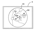
ここでは図7の眼底に投影される検査視標の模式図に示されるように、視野検査視標の投影径Dは、例えば眼底中心部(黄斑部)MではD=d1であり、周辺部へとラジアル方向に遠ざかるにつれて、黄斑部Mから距離w2にある位置p2では直径D=d2、黄斑部Mから距離w3にある位置p3では直径D=d3のように段階的に大きく設定されるようにメモリ83に記憶されているとする。なお距離w2<w3、直径d1<d2<d3とする。
なお検者に検査視標の大きさを分かり易く示すために、モニタ8に検査視標のグラフィックを表示しても良い。
Here, as shown in the schematic diagram of the inspection target projected onto the fundus in FIG. 7, the projection diameter D of the visual field inspection target is, for example, D = d1 at the center of the fundus (macular region) M, and the peripheral portion. As it goes away in the radial direction, the diameter D = d2 is set at a position p2 at a distance w2 from the macula M, and the diameter D = d3 is set to be gradually increased at a position p3 at a distance w3 from the macula M. Are stored in the
Note that a graphic of the inspection target may be displayed on the
以上のような視標呈示部100の駆動制御で、視野検査視標の呈示位置がランダムに切り変えられると共に、視野検査視標の輝度が変更される。このとき、患者は固視標による固視を維持しながら、視野検査視標を認識したら応答ボタン7bを押す。制御部80は、入力信号に基づきそのときの視野検査視標の輝度を、その計測点における患者の認識可能な感度の応答情報としてメモリ83に記憶させる。一方、視野検査視標に対する応答ボタン7bの入力が無い場合には、そのときの視野検査視標の輝度を、計測点における患者が認識できない感度の応答情報としてメモリ83に記憶させる。
By the drive control of the visual
なお本実施形態では眼底の検査部位に応じて検査視標の投影径Dが変更されるため、視細胞密度の変化に対する依存性が取り除かれ、より正規化に近い状態(平坦化された状態)で視野検査結果が得られる。その為、検者は、眼底全体の検査結果と局所領域の検査結果を比較することで、眼底の局所的な感度変化を求めることが容易となる。 In this embodiment, since the projection diameter D of the test target is changed according to the examination site of the fundus, the dependence on the change in the photoreceptor cell density is removed, and the state closer to normalization (flattened state) A visual field inspection result can be obtained. Therefore, the examiner can easily obtain the local sensitivity change of the fundus by comparing the test result of the entire fundus and the test result of the local region.
すべての計測点での視野検査が終了すると、制御部80は眼底視野の感度閾値の分布状態をモニタ8に表示させる。図8に視野感度分布の検査結果の例を示す。検者はモニタ8に表示された視野感度の分布状態から網膜全体の検査結果を確認する。この時、本実施形態では眼底の検査部位に関わらず同じ判断基準で視機能が評価される。つまり従来技術では視野感度の閾値が同じであったとしても、検査結果には視細胞数による差が含まれていた為、各部位の真の感度ではなかった。一方、本発明では視細胞密度の変化による影響を取り除くことで、検者がモニタ8に表示された視野感度の測定結果(数値)によって、局所的な感度変化の差を捉えることができるようにしている。
When the visual field inspection is completed at all measurement points, the
なお上記では検者の手動で検査視標の呈示位置が選択される例を示した。一方、自動的に検査視標が切換え呈示される場合にも、制御部80は呈示視標の黄斑部からの距離(座標)に応じてメモリ83に記憶された検査視標の情報を呼び出すことによって、検査視標の呈示位置に応じて所期の大きさの検査視標を呈示できるようになる。
In the above description, an example is shown in which the examiner's manual display position of the test target is selected. On the other hand, also when the test target is automatically switched and presented, the
なお視細胞密度の変化情報は患者毎に入力されても良い。この場合、眼底検査装置に視機能密度分布を入力するための入力手段を設ける。例えば入力手段にはUSBやLAN等の周知の媒体が用いられる。一方、患者毎に取得される視細胞密度の情報は、例えば患者眼の収差を取り除くための波面補償部を持ち眼底を細胞レベルの高倍率で撮影できる眼底撮影装置で撮影された眼底撮影画像を用いて求められる。 Note that photoreceptor cell density change information may be input for each patient. In this case, input means for inputting the visual function density distribution is provided in the fundus examination apparatus. For example, a known medium such as USB or LAN is used as the input means. On the other hand, photoreceptor cell density information acquired for each patient is obtained by, for example, a fundus photographing image photographed by a fundus photographing apparatus having a wavefront compensation unit for removing aberrations of a patient's eye and capable of photographing the fundus at a high magnification of a cell level. It is calculated using.
以上の構成により、制御部80は入力手段から入力された患者毎の視細胞密度の変化情報(又は眼底の視細胞の減少率の逆数変化率を近似したもの)をメモリ83が記憶する。そして視野検査を行う際に、患者毎に入力された視細胞密度の変化情報に基づき、患者眼の眼底中心部と周辺部に投影する刺激視標のサイズを設定する。このようにすると患者毎により正確な検査結果を得ることができるようになる。
With the above configuration, the
また視細胞の種類毎に視細胞密度の変化情報が保持されても良い。例えば錐体細胞と杆体細胞の夫々の視細胞密度の変化情報をメモリ83に記憶させる。そして錐体細胞の感度(網膜感度)を検査する際には、背景輝度が明順応環境となるように視標呈示部100の輝度を設定すると共に、検査視標のサイズを錐体細胞分布密度の変化率の逆数モデル曲線に従って変化させる。杆体細胞の網膜感度を検査する際には、背景輝度を暗順応環境となるように視標呈示部100の輝度を設定し、検査視標のサイズを杆体細胞密度分布の変化率の逆数モデル曲線に従って変化させる。このようにすると視細胞の種類に応じた視機能検査精度の向上が期待される。
Further, the change information of the photoreceptor cell density may be held for each photoreceptor cell type. For example, information on changes in photoreceptor cell density of cone cells and rod cells is stored in the
なお視細胞密度の変化情報に基づく検査視標の投影径の変更は少なくとも2段階で変更されれば良い。例えば図9に示されるように、黄斑部Mからの距離が、距離の閾値wpよりも近い範囲D1では直径d1の検査視標を投影し、黄斑部Mからの距離が、距離の閾値wpよりも遠い範囲D2では直径d2の検査視標が呈示されるようにしても良い(直径d1<d2)。 Note that the change in the projected diameter of the inspection target based on the change information of the photoreceptor cell density may be changed in at least two stages. For example, as shown in FIG. 9, in a range D1 where the distance from the macular portion M is closer than the distance threshold value wp, an inspection target having a diameter d1 is projected, and the distance from the macular portion M is larger than the distance threshold value wp. However, an inspection visual target having a diameter d2 may be presented in the farther range D2 (diameter d1 <d2).
また上記では視細胞密度の変化情報に基づき検査視標の直径を変更して、視細胞に対する検査視標の投影条件が一定となるようにしている。これ以外にも、検査視標の直径を変えずに、検査視標の密度を変えて、眼底の中央部と周辺部とで検査視標を投影条件が一定となるようにしても良い。例えば、本実施形態では各液晶パネル110〜112の画素のONとOFFとを切換えることで検査視標の密度を変更できる。例えば、図10の模式図に示されるように、黄斑部Mの付近では直径d1の検査視標を形成する画素を所定のステップでOFFとすることで、検査視標で刺激される視細胞の数を制限する。一方、黄斑部Mから離れた部位では、黄斑中央部に比べて各画素のうちONとするものを増やすことで、検査視標で刺激される視細胞の数を増加させるようにする。これにより眼底の中央部と周辺部とで視細胞に対する刺激条件を一定にできる。
Further, in the above, the diameter of the inspection target is changed based on the change information of the photoreceptor density so that the projection condition of the inspection target on the photoreceptor is constant. In addition to this, it is also possible to change the density of the inspection target without changing the diameter of the inspection target so that the projection condition of the inspection target is constant between the central portion and the peripheral portion of the fundus. For example, in this embodiment, the density of the inspection target can be changed by switching the pixels of the
更には上記では視機能に関する細胞として視細胞の閾値を求める例を説明したが、神経節細胞の閾値を検査する場合にも上記と同様に黄斑部からのラジアル方向の距離に応じて眼底に投影する検査視標の投影径を変えることで、細胞数の違いによる影響を抑えた状態で、視機能特性を評価出来るようになる。 Furthermore, in the above description, an example in which the threshold value of a photoreceptor cell is obtained as a cell related to visual function has been described. By changing the projected diameter of the inspection target to be performed, the visual function characteristics can be evaluated in a state where the influence of the difference in the number of cells is suppressed.
1 眼底検査装置
8 モニタ
10 照明光学系
30 観察・撮影光学系
40 フォーカス指標投影光学系
70 視標呈示光学系
80 制御部
83 メモリ
100 視標呈示部
110、111、112 液晶パネル
DESCRIPTION OF
Claims (2)
被検眼に呈示して誘導するための固視標を形成する固視標形成手段と、
被検眼眼底に対する検査視標による検査位置を設定する検査視標設定手段と、
該検査視標設定手段にて設定された前記検査位置に対応する被検眼眼底の検査位置に前記検査視標を投影可能な視標投影手段と、
前記固視標形成手段によって形成される前記固視標の座標と前記検査視標設定手段により設定される前記検査視標の座標に基づいた前記固視標に対する前記検査視標のラジアル方向の距離に応じ、該ラジアル方向の距離が相対的に近い前記検査視標の投影径に対して相対的に遠い前記検査視標の投影径が大きくなるように前記視標投影手段を制御する制御手段と、
を備えることを特徴とする眼底検査装置。 A fundus examination apparatus that inspects the fundus by projecting an examination target on the examination position of the fundus of the subject eye,
Fixation target forming means for forming a fixation target to be presented and guided to the eye to be examined;
An inspection target setting means for setting an inspection position by an inspection target for the fundus of the eye to be examined ;
A target projecting means capable of projecting the test target on the test position of the fundus of the eye corresponding to the test position set by the test target setting unit;
The distance in the radial direction of the inspection target relative to the fixation target based on the coordinates of the fixation target formed by the fixation target forming unit and the coordinates of the inspection target set by the inspection target setting unit And a control means for controlling the target projection means so that a projection diameter of the inspection target that is relatively far from a projection diameter of the inspection target that is relatively close to the radial direction is large. ,
A fundus examination apparatus comprising:
前記検査視標設定手段は更に、眼底上での検査位置及び視機能に関する細胞の種類に応じて前記検査視標の投影条件を設定する眼底検査装置。 The fundus examination apparatus according to claim 1,
The inspection target setting means is further a fundus inspection apparatus that sets projection conditions of the inspection target according to the cell type relating to the inspection position and visual function on the fundus.
Priority Applications (1)
| Application Number | Priority Date | Filing Date | Title |
|---|---|---|---|
| JP2012123939A JP6060525B2 (en) | 2012-05-31 | 2012-05-31 | Fundus examination device |
Applications Claiming Priority (1)
| Application Number | Priority Date | Filing Date | Title |
|---|---|---|---|
| JP2012123939A JP6060525B2 (en) | 2012-05-31 | 2012-05-31 | Fundus examination device |
Publications (3)
| Publication Number | Publication Date |
|---|---|
| JP2013248075A JP2013248075A (en) | 2013-12-12 |
| JP2013248075A5 JP2013248075A5 (en) | 2015-07-16 |
| JP6060525B2 true JP6060525B2 (en) | 2017-01-18 |
Family
ID=49847410
Family Applications (1)
| Application Number | Title | Priority Date | Filing Date |
|---|---|---|---|
| JP2012123939A Expired - Fee Related JP6060525B2 (en) | 2012-05-31 | 2012-05-31 | Fundus examination device |
Country Status (1)
| Country | Link |
|---|---|
| JP (1) | JP6060525B2 (en) |
Cited By (1)
| Publication number | Priority date | Publication date | Assignee | Title |
|---|---|---|---|---|
| US11120577B2 (en) | 2017-02-09 | 2021-09-14 | Komatsu Ltd. | Position measurement system, work machine, and position measurement method |
Families Citing this family (3)
| Publication number | Priority date | Publication date | Assignee | Title |
|---|---|---|---|---|
| JP6898969B2 (en) * | 2015-03-30 | 2021-07-07 | キヤノン株式会社 | Ophthalmic information processing system and ophthalmic information processing method |
| JP6750068B2 (en) * | 2019-05-30 | 2020-09-02 | 株式会社トプコン | Fundus analyzer |
| JP2022025239A (en) * | 2020-07-29 | 2022-02-10 | 株式会社クリュートメディカルシステムズ | Visual inspection apparatus, visual inspection system, and visual inspection program |
Family Cites Families (1)
| Publication number | Priority date | Publication date | Assignee | Title |
|---|---|---|---|---|
| ES2569401T3 (en) * | 2006-03-21 | 2016-05-10 | Novavision Inc. | Process and device to distribute therapeutic vision stimuli |
-
2012
- 2012-05-31 JP JP2012123939A patent/JP6060525B2/en not_active Expired - Fee Related
Cited By (1)
| Publication number | Priority date | Publication date | Assignee | Title |
|---|---|---|---|---|
| US11120577B2 (en) | 2017-02-09 | 2021-09-14 | Komatsu Ltd. | Position measurement system, work machine, and position measurement method |
Also Published As
| Publication number | Publication date |
|---|---|
| JP2013248075A (en) | 2013-12-12 |
Similar Documents
| Publication | Publication Date | Title |
|---|---|---|
| JP5606813B2 (en) | Ophthalmic equipment | |
| JP6354979B2 (en) | Fundus photographing device | |
| WO2016027589A1 (en) | Ophthalmological imaging device and control method therefor | |
| JP6899632B2 (en) | Ophthalmologic imaging equipment | |
| JP2009291409A (en) | Apparatus for measuring refractive power of eye | |
| JP5101370B2 (en) | Fundus photographing device | |
| JP2018047049A (en) | Subjective optometer and subjective optometric program | |
| JP5953740B2 (en) | Fundus examination device | |
| JP6060525B2 (en) | Fundus examination device | |
| JP6853496B2 (en) | Optometry device and optometry program | |
| JP2007275160A (en) | Ophthalmologic apparatus | |
| JP6736356B2 (en) | Ophthalmic equipment | |
| JP2016158721A (en) | Ophthalmologic apparatus | |
| JP6604020B2 (en) | Fundus imaging apparatus and fundus imaging program | |
| JP6003234B2 (en) | Fundus photographing device | |
| JP2023171595A (en) | Ophthalmologic apparatus | |
| JP2016049243A (en) | Ophthalmologic apparatus | |
| JP2013244363A (en) | Fundus photographing apparatus | |
| JP6452977B2 (en) | Ophthalmic imaging apparatus and control method thereof | |
| JP4851176B2 (en) | Optical target presentation optical device | |
| JP2017143919A (en) | Ophthalmologic apparatus | |
| JP2017143918A (en) | Ophthalmologic apparatus | |
| JP2016140423A (en) | Ophthalmologic apparatus | |
| WO2023145638A1 (en) | Ophthalmic device and ophthalmic program | |
| WO2016129499A1 (en) | Ocular refractivity measuring device |
Legal Events
| Date | Code | Title | Description |
|---|---|---|---|
| A521 | Request for written amendment filed |
Free format text: JAPANESE INTERMEDIATE CODE: A523 Effective date: 20150527 |
|
| A621 | Written request for application examination |
Free format text: JAPANESE INTERMEDIATE CODE: A621 Effective date: 20150527 |
|
| A977 | Report on retrieval |
Free format text: JAPANESE INTERMEDIATE CODE: A971007 Effective date: 20160329 |
|
| A131 | Notification of reasons for refusal |
Free format text: JAPANESE INTERMEDIATE CODE: A131 Effective date: 20160419 |
|
| A521 | Request for written amendment filed |
Free format text: JAPANESE INTERMEDIATE CODE: A523 Effective date: 20160620 |
|
| TRDD | Decision of grant or rejection written | ||
| A01 | Written decision to grant a patent or to grant a registration (utility model) |
Free format text: JAPANESE INTERMEDIATE CODE: A01 Effective date: 20161115 |
|
| A61 | First payment of annual fees (during grant procedure) |
Free format text: JAPANESE INTERMEDIATE CODE: A61 Effective date: 20161128 |
|
| R150 | Certificate of patent or registration of utility model |
Ref document number: 6060525 Country of ref document: JP Free format text: JAPANESE INTERMEDIATE CODE: R150 |
|
| R250 | Receipt of annual fees |
Free format text: JAPANESE INTERMEDIATE CODE: R250 |
|
| R250 | Receipt of annual fees |
Free format text: JAPANESE INTERMEDIATE CODE: R250 |
|
| R250 | Receipt of annual fees |
Free format text: JAPANESE INTERMEDIATE CODE: R250 |
|
| LAPS | Cancellation because of no payment of annual fees |