WO2023074855A1 - Image processing device - Google Patents
Image processing device Download PDFInfo
- Publication number
- WO2023074855A1 WO2023074855A1 PCT/JP2022/040409 JP2022040409W WO2023074855A1 WO 2023074855 A1 WO2023074855 A1 WO 2023074855A1 JP 2022040409 W JP2022040409 W JP 2022040409W WO 2023074855 A1 WO2023074855 A1 WO 2023074855A1
- Authority
- WO
- WIPO (PCT)
- Prior art keywords
- image processing
- history
- screen
- displayed
- button
- Prior art date
Links
- 238000012545 processing Methods 0.000 title claims abstract description 226
- 238000004891 communication Methods 0.000 claims description 48
- 230000007704 transition Effects 0.000 claims description 11
- 230000006870 function Effects 0.000 description 73
- 238000000034 method Methods 0.000 description 11
- 238000010586 diagram Methods 0.000 description 10
- 230000036961 partial effect Effects 0.000 description 9
- 230000015654 memory Effects 0.000 description 7
- 230000005540 biological transmission Effects 0.000 description 5
- 230000008859 change Effects 0.000 description 3
- 230000008094 contradictory effect Effects 0.000 description 3
- 239000011521 glass Substances 0.000 description 3
- 230000008569 process Effects 0.000 description 3
- 238000006243 chemical reaction Methods 0.000 description 2
- 238000012217 deletion Methods 0.000 description 2
- 230000037430 deletion Effects 0.000 description 2
- 238000001514 detection method Methods 0.000 description 2
- 238000005401 electroluminescence Methods 0.000 description 2
- 230000014509 gene expression Effects 0.000 description 2
- 238000010079 rubber tapping Methods 0.000 description 2
- 238000012795 verification Methods 0.000 description 2
- 230000009471 action Effects 0.000 description 1
- 238000013475 authorization Methods 0.000 description 1
- 239000003086 colorant Substances 0.000 description 1
- 239000000470 constituent Substances 0.000 description 1
- 230000003247 decreasing effect Effects 0.000 description 1
- 230000008034 disappearance Effects 0.000 description 1
- 230000005674 electromagnetic induction Effects 0.000 description 1
- 238000010438 heat treatment Methods 0.000 description 1
- 238000003384 imaging method Methods 0.000 description 1
- 239000004973 liquid crystal related substance Substances 0.000 description 1
- 239000000203 mixture Substances 0.000 description 1
- 108091008695 photoreceptors Proteins 0.000 description 1
- 230000002441 reversible effect Effects 0.000 description 1
- 230000003068 static effect Effects 0.000 description 1
- 238000010897 surface acoustic wave method Methods 0.000 description 1
Images


Classifications
-
- B—PERFORMING OPERATIONS; TRANSPORTING
- B41—PRINTING; LINING MACHINES; TYPEWRITERS; STAMPS
- B41J—TYPEWRITERS; SELECTIVE PRINTING MECHANISMS, i.e. MECHANISMS PRINTING OTHERWISE THAN FROM A FORME; CORRECTION OF TYPOGRAPHICAL ERRORS
- B41J29/00—Details of, or accessories for, typewriters or selective printing mechanisms not otherwise provided for
- B41J29/38—Drives, motors, controls or automatic cut-off devices for the entire printing mechanism
-
- B—PERFORMING OPERATIONS; TRANSPORTING
- B41—PRINTING; LINING MACHINES; TYPEWRITERS; STAMPS
- B41J—TYPEWRITERS; SELECTIVE PRINTING MECHANISMS, i.e. MECHANISMS PRINTING OTHERWISE THAN FROM A FORME; CORRECTION OF TYPOGRAPHICAL ERRORS
- B41J29/00—Details of, or accessories for, typewriters or selective printing mechanisms not otherwise provided for
- B41J29/42—Scales and indicators, e.g. for determining side margins
-
- G—PHYSICS
- G06—COMPUTING; CALCULATING OR COUNTING
- G06F—ELECTRIC DIGITAL DATA PROCESSING
- G06F3/00—Input arrangements for transferring data to be processed into a form capable of being handled by the computer; Output arrangements for transferring data from processing unit to output unit, e.g. interface arrangements
- G06F3/01—Input arrangements or combined input and output arrangements for interaction between user and computer
- G06F3/048—Interaction techniques based on graphical user interfaces [GUI]
- G06F3/0481—Interaction techniques based on graphical user interfaces [GUI] based on specific properties of the displayed interaction object or a metaphor-based environment, e.g. interaction with desktop elements like windows or icons, or assisted by a cursor's changing behaviour or appearance
- G06F3/04817—Interaction techniques based on graphical user interfaces [GUI] based on specific properties of the displayed interaction object or a metaphor-based environment, e.g. interaction with desktop elements like windows or icons, or assisted by a cursor's changing behaviour or appearance using icons
-
- H—ELECTRICITY
- H04—ELECTRIC COMMUNICATION TECHNIQUE
- H04N—PICTORIAL COMMUNICATION, e.g. TELEVISION
- H04N1/00—Scanning, transmission or reproduction of documents or the like, e.g. facsimile transmission; Details thereof
Definitions
- Image processing refers to various types of processing related to image handling, such as image printing, image scanning, and image file transmission/reception.
- Patent Document 1 An image processing device capable of displaying the history of image processing is known (for example, Patent Document 1 below).
- the image processing apparatus disclosed in Patent Document 1 displays a plurality of buttons (history buttons) related to the history of image processing arranged in order of execution date and time of the image processing on the operation panel.
- Each history button displays the type of image processing (copy, scan, etc.), image processing conditions (number of copies, color or monochrome printing, single-sided/double-sided printing, etc.), and execution date and time of image processing.
- the image processing conditions corresponding to that history button are set as the conditions for image processing to be performed from now on. Thereby, the conditions set in the past can be easily used.
- An image processing apparatus includes an operation panel capable of realizing a predetermined display form.
- the operation panel is capable of displaying a main screen and a sub-screen.
- the main screen has a menu area in which a plurality of function buttons corresponding to types of image processing are arranged.
- the sub-screen has a reception area that transitions from the main screen after one of the function buttons is selected and receives an image processing instruction for the selected function button.
- a first history display area displaying a plurality of history buttons including information on image processing completed in the past, specialized for image processing corresponding to the selected function button, is arranged side by side with the reception area. is displayed.
- FIG. 1 is an external view of an image processing apparatus according to an embodiment
- FIG. 1 is a block diagram showing an example of the configuration of an image processing apparatus according to an embodiment
- FIG. 2 is a view showing an example of a main screen displayed on the operation panel of the image processing apparatus of FIG. 1
- FIG. FIG. 4 is a view showing an example of a sub-screen (copy) transitioned from the main screen of FIG. 3
- FIG. 4 is a view showing an example of a sub-screen (fax) transitioned from the main screen of FIG. 3
- FIG. 4 is a diagram showing an example of a sub-screen (mail) transitioned from the main screen of FIG. 3
- FIG. 1 is an external view of an image processing apparatus according to an embodiment
- FIG. 1 is a block diagram showing an example of the configuration of an image processing apparatus according to an embodiment
- FIG. 2 is a view showing an example of a main screen displayed on the operation panel of the image processing
- FIG. 8 is a diagram showing an example of a sub-screen (copy) transitioned from the main screen of FIG. 7; The figure which shows an example of a main screen when fixed display is set by a main screen.
- FIG. 10 is a view showing an example of a sub-screen (copy) transitioned from the main screen of FIG. 9; The figure which shows an example of a subscreen when a fixed display is set by a subscreen (copy).
- FIG. 12 is a diagram showing an example of a main screen transitioned from the sub-screen of FIG. 11;
- FIG. 13 is a diagram showing an example of a main screen from the main screen shown in FIG. 9 or 12 via the sub-screen (FAX) shown in FIG. 5;
- FIG. 13 is a view showing another example of the main screen from the main screen of FIG. 9 or 12 via the sub-screen (FAX) of FIG. 5;
- FIG. 1 is an external view of an image processing device 1 according to an embodiment
- FIG. 2 is a block diagram showing the configuration of the image processing device 1. As shown in FIG.
- the image processing apparatus 1 is configured as a multifunction device, and has, for example, the following configuration.
- Printer 3 for printing.
- a scanner 5 for reading an image.
- a communication unit 7 that communicates with the outside.
- An operation panel 9 for accepting user operations.
- a CPU 11 Central Processing Unit
- a storage unit 13 that stores various information.
- a housing 15 that holds these configurations.
- the operation panel 9 is provided on the top of the housing 15 and includes a touch panel.
- the operation panel 9 may include operation targets other than the touch panel, such as physical buttons. However, in the description of the embodiment, expressions may be made assuming that the operation panel 9 is composed only of a touch panel.
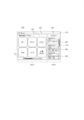
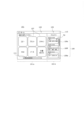
- FIG. 3 is a diagram showing an example of the main screen 101 displayed on the operation panel 9.
- FIG. Here, a home screen is shown as an example of the main screen 101 .
- the main screen 101 is, for example, a screen that is displayed when the user starts using the image processing apparatus 1 or is in a standby state. From another point of view, the main screen 101 is displayed when the image processing apparatus 1 is powered on, when the image processing apparatus 1 returns from the sleep mode, and/or when user authentication is successful in the image processing apparatus 1. , is the screen that is launched.
- a menu area 101a and a history display area (timeline display area) 101b are displayed side by side.
- the menu area 101 a displays a partial area of the main area 103 .
- the range occupied by the partial area in the main area 103 may be indicated by a scroll bar 111 .
- a history display area 101 b displays a partial area of the history area (timeline area) 105 .
- the range occupied by the partial area in history area 105 may be indicated by scroll bar 113 .
- a plurality of function buttons 107 corresponding to the types of image processing are arranged in the menu area 101a (main area 103).
- a plurality of function buttons 107 are for selecting any one function from mutually different functions (image processing from another point of view).
- the function button 107 displays information on the function corresponding to itself. In FIG. 3, "copy”, “print”, “scan”, “FAX” (facsimile), "mail” and "document box” are illustrated as functions.
- a predetermined operation for example, one touch (for example, tap)
- any function button 107 for example, the screen displayed on the operation panel 9 changes to the function corresponding to that function button 107. Switches to a screen (sub-screen 121 (eg, FIG. 4)) for performing an operation.
- the operation related to the function is, for example, an operation of executing image processing and an operation of setting image processing conditions (for example, the size of paper for copying).
- the history area 105 has a plurality of history buttons 109.
- Each history button 109 contains (displays) information about image processing (functions) performed in the past.
- the image processing information displayed on the history button 109 includes the date and time when the image processing was executed, the type of image processing ("copy", “fax”, or “mail” is exemplified in FIG. 3), Image processing conditions ("color”, “black and white”, etc. are exemplified in FIG. 3).
- the history button 109 may display a communication destination (hereinafter also referred to as a destination).
- the screen displayed on the operation panel 9 displays, for example, history information corresponding to the history button 109. Switches to a history use screen (not shown) for use.
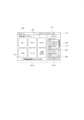
- FIG. 4 is a diagram showing an example of the sub-screen 121 displayed on the operation panel 9.
- the subscreen 121 is a screen regarding image processing corresponding to the selected function button 107 .
- the sub-screen 121 includes a reception area 121a for receiving an image processing instruction for the currently selected function button 107, and a plurality of screens including information on previously completed image processing specialized for image processing corresponding to the currently selected function button 107.
- a history display area 121b including a history button 134 is displayed side by side.
- the history display area 121 b displays a partial area of the history area (timeline area) 135 .
- the range occupied by the partial area in history area 135 may be indicated by scroll bar 123 .
- the image processing apparatus 1 has a function of identifying a user (and a function of authenticating a user) (unless otherwise specified or contradictory, user groups are included; the same shall apply hereinafter). It may or may not have In order to simplify the explanation, for the sake of convenience, the aspect that does not require such an identification function and the authentication function will be referred to as the first embodiment, and the aspect that assumes the authentication function will be referred to as the second embodiment, and will be described in order. . However, for the sake of convenience, the description of the first embodiment may also refer to information, configurations, and operations on the premise that the image processing apparatus 1 has a function of identifying (and authenticating) a user. .
- image may include only characters.
- image data may be in various formats, such as vector format or raster format. In the description of the embodiments, for the sake of convenience, "image” and “image data” may not be strictly distinguished.
- Image data may be appropriately converted in format in the process of image processing.
- the image data stored in the image processing apparatus 1 may differ from the image data when image processing (for example, printing, scanning, facsimile, transmission/reception of image files, etc.) is performed.
- image processing for example, printing, scanning, facsimile, transmission/reception of image files, etc.
- the description of such format conversion may be omitted, and the image data before and after conversion may be described as being the same.
- the image data may be changed such that the image quality is changed or a part of the image is cut out when image processing is performed. Even in such a case, the image data before and after the change may not be distinguished in the description of the embodiment for the sake of convenience.
- Information displayed on various parts of various screens of the operation panel 9 may be displayed by text and/or by symbol images, for example.
- the information is , text and/or symbol images.
- Information is displayed on, for example, history buttons 109 and 134, function button 107, execution button 125, setting button 131 (described later), return button 133 (described later), areas around these buttons, and Title bars 115 and 127 (discussed below) are included.
- Text may refer to, for example, information displayed as a character string and/or information displayed based on text data.
- the text may be a character string displayed based on image data, or a symbol or only one character displayed based on text data.
- a “symbol image” may refer to information displayed as, for example, a symbol or graphic, and/or information displayed based on image data. Therefore, for example, the symbol image may be a symbol displayed based on text data, or one or more characters displayed based on image data.
- text and symbol images may be partially overlapping classifications.
- buttons displayed on the operation panel 9 do not have to imitate physical buttons.
- a button may only be represented by text and/or symbolic images and not have a border surrounding the text and/or symbolic images.
- the boundary between the region where the user's operation is detected and the surrounding region may not be represented by a frame line or different colors.
- the image processing apparatus 1 shown in FIGS. 1 and 2 has an operation panel 9 and a configuration capable of performing one or more types of image processing.
- the specific configuration may be various configurations, for example, it may be a known configuration.
- the printer 3, the scanner 5, and the communication section 7 are provided as a configuration for performing image processing, as described above. Aspects different from the present embodiment include, for example, a aspect in which only one of the printer 3 and the scanner 5 is provided, and an aspect in which the communication section 7 is not provided.
- the configuration of each unit (3, 5, 7, 9, 11 and 13) of the image processing apparatus 1 may be of various configurations, for example, may be a known configuration.
- the image processing apparatus 1 has, for example, a housing 15 housing the various components (3, 5, 7, 9, 11 and 13) described above.
- the size and shape of the image processing device 1 (or housing 15 from another point of view) are arbitrary.
- the image processing apparatus 1 may have a size (mass) that can be carried by one person, such as a multifunction machine or printer for home use, or a multifunction machine or printer for business use.
- a single person may have an unportable size (mass).
- the operation method of the image processing device 1 is arbitrary.
- the image processing apparatus 1 may be placed at home for home or personal use, may be placed at a company for use by a specific number of users, or may be placed at a convenience store or the like. It may be placed in a store and used by an unspecified number of users. Note that if it is assumed that an unspecified number of users will use the image processing apparatus 1, the image processing apparatus 1 may authenticate the user and permit access only to the image data related to that user.
- the configuration of the printer 3 is arbitrary.
- the printer 3 may be configured to print on paper (sheet paper from another point of view) arranged in a tray (not shown) and to discharge the printed paper.
- the printer 3 may have only one tray, or may have multiple trays. Multiple trays, for example, help accommodate different size sheets. From another point of view, the printer 3 may or may not have the function of selecting the paper size. Note that the former will be taken as an example in the description of the present embodiment.
- the printer 3 may be configured to perform color (and monochrome and grayscale) printing, may be configured to perform only grayscale (and monochrome) printing, or may be configured to perform monochrome printing. It may be a configuration in which only Note that in the description of the present embodiment, a configuration capable of color printing is taken as an example.
- the printer 3 may be an inkjet printer that prints by ejecting ink, or a thermal printer that prints by heating thermal paper or an ink ribbon. It may also be an electrophotographic printer (for example, a laser printer) that transfers toner adhering to a photoreceptor.
- the inkjet printer may be of the piezo type in which pressure is applied to the ink by a piezoelectric body, or may be of the thermal type in which pressure is applied to the ink by air bubbles generated in the ink to which heat is applied.
- the printer 3 may be a line printer having a head that spans the width of the paper (a direction crossing the paper transport direction), or a serial printer in which the head moves in the width direction of the paper. There may be.
- the scanner 5 captures and scans an original placed on the original glass with a plurality of imaging elements that move along the original glass under the original glass.
- the communication unit 7 realizes communication between the image processing device 1 and other devices.
- Other devices include, for example, personal computers (PCs), mobile terminals (smartphones, etc.), other image processing devices, and servers.
- Examples of servers include file servers, mail servers, and web servers.
- Communication may be performed directly with another device, or may be performed indirectly via a network.
- Networks include, for example, telephone networks, the Internet, private networks, and LANs (Local Area Networks). Communication may be wired communication, wireless communication, short-range communication, or long-distance communication.
- the image processing apparatus 1 may be configured to allow any one or more of the various communications described above.
- the image processing apparatus 1 is exemplified by a mode capable of various communications as described above.
- the communication unit 7 includes various components for realizing various communications as described above.
- the communication unit 7 may be regarded as including only hardware configuration (for example, connector, antenna, amplifier, filter, RF (Radio Frequency) circuit), or in addition to the hardware configuration, software configuration (a functional unit constructed by a CPU executing a program).
- the operation panel 9 includes a touch panel as described above. Although not shown, the touch panel has a display device and a position input device that overlaps the screen of the display device.
- the configuration of the display device and the position input device is arbitrary.
- the display device may be configured by a liquid crystal display or an organic EL (Electro Luminescence) display. These displays have a relatively large number of regularly arranged pixels and are capable of displaying an image containing arbitrary shapes based on image data.
- the display device may be capable of displaying color images, may be capable of displaying only grayscale images (and monochrome images), or may be capable of displaying only monochrome images (binary images). good too.
- the position input device may be of an electrostatic type or of a pressure-sensitive type. Capacitive ones sense the change in capacitance in and/or near the screen that accompanies the contact or proximity of a finger or pen. Pressure sensitive ones sense the pressure applied to the screen.
- the position input device may be one that uses surface acoustic waves, one that uses infrared light, or one that uses electromagnetic induction. Also, the position input device may or may not require a dedicated pen.
- the CPU 11 builds functional units that execute various processes by executing programs stored in the storage unit 13 .
- the functional unit may be a control unit.
- the control unit controls operations of the printer 3 , scanner 5 , communication unit 7 and operation panel 9 .
- the control unit may include a logic circuit configured to perform only a certain operation.
- the storage unit 13 includes, for example, various memories such as ROM (Read Only Memory), RAM (Random Access Memory), and auxiliary storage, although not shown.
- ROM Read Only Memory
- RAM Random Access Memory
- auxiliary storage although not shown.
- storage part 13 may be grasped as a computer.
- a program for the above-described CPU 11 to construct the control unit 17 is stored, for example, in the ROM of the storage unit 13 and/or an auxiliary storage device.
- bus 21 The various components (3, 5, 7, 9, 11 and 13) mentioned above are connected by a bus 21, for example.
- all components are schematically connected to one bus 21 .
- multiple buses may be connected in any suitable fashion.
- an address bus, a data bus and a control bus may be provided.
- crossbar switches and/or link buses may be applied.
- An interface (not shown) may be interposed between the bus 21 and each unit (3, 5, 7, 9, etc.).
- FIG. 2 is only a schematic diagram. Therefore, for example, a plurality of CPUs and storage units (control units from another point of view) may be provided in a distributed manner.
- a CPU included in each unit (3, 5, 7 and/or 9) (from another point of view, a control unit that controls each unit) and a higher CPU (a higher control unit that controls the control unit of each unit) and may be provided.
- the control unit referred to in the description of the embodiments may be regarded as a high-level control unit, or may be regarded as a combination of the control unit of each unit and a high-level control unit.
- the control section and each section (3, 5, 7 and/or 9) are not necessarily clearly distinguishable.
- Main screen 101 shown in FIG. 3 is displayed over the entire screen of the operation panel 9, for example.
- Main screen 101 may include (or may be displayed on) main area 103, history area 105, and scroll bars 111 and 113, for example, as described above.
- the history display area 101b includes a plurality of history buttons 109 containing information on image processing completed in the past with respect to a plurality of types of image processing corresponding to the function buttons 107 in the menu area 101a.
- the main screen 101 may include appropriate parts such as the title bar 115 at the top.
- the display mode of the main area 103 and the process executed when one of the function buttons 107 is selected may be various, and may be similar to known ones, for example.
- part of the main area 103 is displayed in the menu area 101a.
- the entire main area 103 may be displayed in the menu area 101a.
- the plurality of function buttons 107 may be provided in a number larger than the upper limit number that can be displayed simultaneously (example in the figure), or may be provided in a number equal to or less than the upper limit number.
- the scrolling direction horizontal direction in the illustrated example
- the number of function buttons 107 and the types of functions corresponding to the function buttons 107 may be set as appropriate.
- the number of function buttons 107 may be increased or decreased by the user.
- the function buttons 107 illustrated in FIG. 3 are as follows.
- function button 107 may be referred to by the text displayed within the function button 107 . The same is true for other buttons.
- Coding is for setting and/or executing a function (copy function) for printing an image read by the scanner 5 with the printer 3.
- Print is for setting and/or executing a function of printing an image based on data stored in a recording medium (not shown) connected to the image processing apparatus 1 with the printer 3, for example.
- the storage medium is, for example, a USB (Universal Serial Bus) memory.
- the term “printing” is not limited to “printing” of the function button 107 (for example, printing by receiving a print job from the outside). may include prints.)
- “Scan” is for setting and/or executing the function of saving the image read by the scanner 5 as data.
- the storage destination is, for example, an auxiliary storage device (non-volatile memory from another point of view) included in the storage unit 13, a storage medium connected to the image processing apparatus 1, or It is another device that communicates.
- the term “scanning” is not limited to “scanning” of the function button 107 unless otherwise specified or contradictory (for example, scanning performed in copying is included). sometimes.) Note that
- FAX is for settings and/or execution related to FAX.
- FAX transmission for example, an image of a document to be transmitted is read by the scanner 5 , and data of the read image is transmitted by the communication section 7 .
- receiving a FAX for example, image data is received by the communication unit 7 and the printer 3 performs printing based on the received image data.
- "Email” is for setting and/or executing e-mails, and is used for sending and confirming receipt of e-mails with attached image files.
- this function for example, part or all of the content of the mail received by the communication unit 7 may be printed by the printer 3 .
- the image data read by the scanner 5 may be attached to an email in the form of an image file and transmitted by the communication unit 7 .
- the image data stored in the document box may be attached in the form of an image file and included in the mail sent by the communication unit 7 .
- the "document box” is used to view information of an arbitrary number of image data stored in an auxiliary storage device (non-volatile memory from another point of view) included in the storage unit 13, for example, and to create an image for the selected image data. It is for setting and/or executing functions for executing processing. Image processing is, for example, printing, transmission by FAX, or transmission by e-mail.
- FIG. 4 shows a sub-screen to which a transition is made when the function button 107 corresponding to "copy" is selected.
- the display mode of the history area 105 may be various, for example, it may be the same as a known one.
- the position, shape and area of the history display area 101b are arbitrary.
- the history display area 101b is located on one side of the horizontal direction (the right side ) and has a rectangular shape with the vertical direction as the longitudinal direction.
- the width of the history display area 101 b is less than 1/2 or 1/3 of the width of the main screen 101 . Note that most of the main screen 101 excluding the history display area 101b (for example, 80% or more) is the menu area 101a.
- part of the history area 105 is displayed in the history display area 101b.
- the entire history area 105 may be displayed in the history display area 101b.
- the plurality of history buttons 109 may be provided in a number greater than the upper limit number that can be displayed simultaneously (example in the figure), or may be provided in a number equal to or less than the upper limit number.
- the scrolling direction (vertical direction in the illustrated example) is arbitrary.
- a plurality of history buttons 109 are arranged in a row in a predetermined direction, for example, in the order of the date and time when the image processing corresponding to the history button 109 was executed.
- the direction in which the plurality of history buttons 109 are arranged is arbitrary. In the example of FIG. 3, the alignment direction is the vertical direction of the main screen 101, the longitudinal direction of the history display area 101b, and the direction in which the history area 105 is scrolled.
- the plurality of history buttons 109 may be arranged from one side to the other (in the illustrated example, from top to bottom) in order of newest (in the example shown), or in order of oldest. By performing a predetermined operation on the operation panel 9, it may be possible to switch between the newest order and the oldest order. In addition, in description of this embodiment, for convenience, it is premised that they are arranged in reverse chronological order.
- a new history button 109 related to that image processing is added. If the image processing that was the basis for adding the history button 109 and the new image processing that was performed via the operation of the history button 109 are the same, even if the history button 109 is newly added. Alternatively, the execution date and time of the image processing corresponding to the operated history button 109 may be updated (from another point of view, the display position of the history button 109 may be changed). The same image processing referred to here may be, for example, the same except for execution date and time. However, there may be differences other than the execution date and time. Note that the history button 109 does not have to be added for image processing executed via an operation on the history button 109, unlike the description of the present embodiment.
- the type of image processing for which the history button 109 is generated is arbitrary. For example, even if the image processing apparatus 1 has the six functions illustrated on the main screen 101, the history buttons 109 need not be generated for all of them.
- the history button 109 may be generated only for image processing in which printing is performed by the image processing apparatus 1, such as "copy” and “print” (and printing in the "document box”).
- the history button 109 may be generated only for image processing such as “copy”, “scan”, “fax”, and “email” in which scanning is performed by the image processing apparatus 1.
- the history button 109 may be generated only for image processing that does not involve communication, such as "copy", "print”, and “scan” (and printing with a "document box”).
- the history button 109 may or may not be added for image processing performed by sending a signal including a print job or the like from another device (eg, a PC) to the communication unit 7 .
- a PC e.g., a PC
- the history button 109 can be omitted.
- an instruction to execute image processing by a signal from the outside is added to the place where the instruction to execute image processing for the operation panel 9 is described. you can
- the number of history buttons 109 provided in the history area 105 is limited to a predetermined upper limit or less.
- the number of history buttons 109 (including those displayed by scrolling) that can be displayed in the history display area 101b is limited to a predetermined upper limit value or less. Therefore, for example, as described above, the history buttons 109 are added, and after the number of history buttons 109 reaches the upper limit, when a new history button 109 is added, the oldest history button 109 is deleted. be done. In other words, the oldest history button 109 becomes non-displayable.
- the specific value of the above upper limit is arbitrary, and examples are 5, 10, or 20.
- the upper limit value may be set by the manufacturer of the image processing device 1 and may not be changed by the administrator or user of the image processing device 1, or may be set by the administrator of the image processing device 1. good too.
- the upper limit value may be set by the user.
- the display mode when the number of history buttons 109 does not reach the upper limit is arbitrary. For example, only the number of history buttons 109 less than the upper limit may be displayed, or a dummy history button (for example, a history button that does not display information inside) may be displayed together so that the total number of history buttons 109 equals the upper limit. may be displayed. In the former mode, the length of history area 105 may or may not change depending on the number of history buttons 109 .
- the image processing apparatus 1 may be capable of performing operations different from those described above regarding addition, deletion, and placement of the history button 109 .
- an operation for example, long-tapping or double-tapping
- Deletion of the history button 109 may be prohibited, the history button 109 may be always arranged above the newest history button 109, or the history button 109 may be deleted.
- the description or expression may be made on the premise that such an operation will not be performed.
- the plurality of history buttons 109 may have, for example, the same shape and size (example shown), or may have different shapes and/or sizes. As an example of the latter, there can be cited a mode in which the plurality of history buttons 109 have different shapes and/or sizes depending on the type of image processing (differences in copying, scanning, etc.).
- Each history button 109 contains (displays) information on the corresponding image processing.
- the information includes, for example, the date and time when image processing was performed, the type of image processing, the conditions of image processing, and the name of the user who performed the image processing.
- Other examples include communication destinations (destinations and/or reception destinations) in FAX and/or mail functions.
- Information on image processing may include information on image data handled in image processing.
- the image data information includes, for example, the size of the image data, the type of image (document or not) determined by the image processing apparatus 1, and the name given to the image data by the image processing apparatus 1. . Note that in the description of the present embodiment, for the sake of convenience, the description of image data information as image processing information is omitted.
- Each history button 109 may display at least one or more of the various types of information (for example, date and time, type, processing conditions, user name, and communication destination) regarding the image processing described above.
- the image processing conditions include various specific conditions, as illustrated in the description of FIG. 3 and the descriptions of FIGS. 4 to 6 below.
- the specific conditions to be displayed may be appropriately selected.
- FIG. 3 exemplifies the color condition (“color” or “black and white” is exemplified), the magnification setting (“100%” is exemplified), and the paper condition (“A4” is exemplified).
- the types of image processing information included in the history buttons 109 may be the same or different between the history buttons 109.
- the type of information displayed on the history button 109 may differ depending on the type of image processing. More specifically, for example, the history button 109 whose type of image processing is copy does not have an item for displaying the communication destination, while the history button 109 whose type of image processing is FAX or e-mail , may have an item for displaying the contact.
- the history information corresponding to the history button 109 can be used. For example, new image processing may be performed under the image processing conditions included in the history information. Also, the type of image processing included in the history information may be performed. There may be various specific modes for realizing the utilization of such history information. For example, as described above, the screen may transition to the history use screen. The history use screen may be the same as or similar to the sub-screen 121, for example. At this time, the processing conditions included in the history information may be set as the processing conditions. Then, either as it is or after the processing conditions are adjusted by the setting button (see setting button 131), new image processing may be performed by operating the execution button (see execution button 125).
- the sub-screen 121 shown in FIG. 4 includes a receiving area 121a for receiving an instruction for image processing related to the currently selected function button 107, and information on previously completed image processing specialized for image processing corresponding to the currently selected function button 107. are displayed side by side.
- the sub-screen 121 includes (displays) an execution button 125, a setting button 131, and a history button 134.
- the history button 134 includes information on image processing completed in the past, specifically for image processing corresponding to the function button 107 being selected on the main screen 101 (FIG. 3).
- the history button 134 contains information on image processing completed in the past specifically for "copy”. It shows that The history button 134 may be displayed using scrolling.
- the direction of scrolling (vertical direction in the illustrated example) is arbitrary.
- the setting button 131 is for confirming and setting setting items such as image processing conditions.
- the setting button 131 may be used to confirm and set setting items (for example, communication destination) other than the processing conditions. However, below, processing conditions may be taken as an example without any particular notice.
- the sub-screen 121 may include (or display) the following, for example. Title bar 127 of sub screen 121 .
- a return button 133 for returning to the main screen 101 .
- FIG. 4 is just an example.
- an area (accepting area 121a) in which a plurality of setting buttons 131 are arranged and an area (history display area 121b) in which a plurality of history buttons 134 are arranged are provided.
- a history display area 121b is displayed side by side with the reception area 121a.
- the reception area 121a and the history display area 121b are arranged in the left-right direction in the above order.
- the position, shape and/or area of the history display area 121b may be the same as the position, shape and/or area of the history display area 101b of the main screen 101 (example shown) or may be different. In any case, the above description regarding the position, shape, and area of the history display area 101b (and the menu area 101a) may be applied to the history display area 121b (accepting area 121a).
- a plurality of setting buttons 131 are provided corresponding to, for example, a plurality of setting items (eg, processing conditions).
- a screen or window for setting the corresponding item is displayed on the operation panel 9 .
- changes can be made from the current settings with respect to the corresponding items.
- the setting button 131 displays information indicating the type of setting item corresponding to itself. Also, the setting button 131 may display information indicating the setting state of the item corresponding to itself. In the illustrated example, the upper portion of the setting button 131 indicates the type of setting item, and the lower portion of the setting button 131 indicates the current setting state of the item.
- the number and types of setting buttons 131 are arbitrary.
- the setting buttons 131 when the history button 109 corresponding to copying is selected are “select paper”, “color/black and white”, “density”, “reduce/enlarge”, “combine pages” and “Single sided/double sided” is exemplified.
- Below the setting button 131 "A4", "color”, “normal”, “100%”, “not set”, and “single-sided” are exemplified as the current settings of these items. Since these are commonly used, descriptions thereof will be omitted.
- the history button 134 on the sub-screen 121 includes information on image processing completed in the past, specifically for image processing corresponding to the function button 107 selected on the main screen 101 .
- the image processing information displayed on the history button 134 includes text or a symbol image related to at least one of the image processing type, processing conditions, processing date and time, user name, and communication destination.
- Types of image processing include at least copying, scanning, and facsimile.
- "copy" is exemplified as the type of image processing of the history button 134, specifically for the currently selected "copy” function.
- the processing conditions include at least one of image quality and page layout.
- the image processing conditions include color conditions for image quality (“color” or “black and white” are examples), magnification settings for page layout (“100%” or “70%” are examples), and paper size. Conditions (“A4" or “automatic” are exemplified) are illustrated.
- the specific display mode (position, shape, area, display content, generation and disappearance, etc.) of the history button 134 may be the same as or different from that of the history button 109 on the main screen 101 .
- the function button 107 for "copy” is selected and the subscreen 121 is displayed, it is clear that the history button 134 contains information specific to "copy”. In contrast, "copy” information may not be included.
- the above explanation regarding the specific display mode etc. of the history button 109 is limited to image processing corresponding to the selected function button 107. It may be incorporated into the history button 134 .
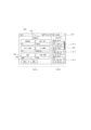
- FIG. 5 shows an example of a sub-screen 121 transitioned from the main screen 101 after selecting the "FAX" function button 107 on the main screen 101 of FIG.
- the example shown in FIG. 5 indicates that when the function button 107 for "FAX" is selected on the main screen 101 (FIG. 3), a history button 134 specialized for "FAX" is displayed.
- the setting button 131 of the sub-screen 121 also includes an address book button or numeric keypad for entering a FAX destination.
- FIG. 6 shows an example of a sub-screen 121 transitioned from the main screen 101 after selecting the "mail" function button 107 on the main screen 101 of FIG.
- the example shown in FIG. 6 indicates that when the function button 107 for "mail" is selected on the main screen 101 (FIG. 3), a history button 134 specialized for "mail" is displayed.
- the data of the image read by the scanner 5 may be included in the mail sent by the communication unit 7, or the image data saved in the document box may be sent.
- the data may be included in the mail sent by the communication unit 7 .
- the setting button 131 of the sub-screen 121 also includes a "document box” button for accessing the document box.
- the history information corresponding to the history button 134 can be used. For example, new image processing may be performed under the image processing conditions included in the history information. There may be various specific modes for realizing the utilization of such history information. For example, when a predetermined operation is performed on the history button 134 on the sub-screen 121, the currently set processing conditions are changed to the processing conditions included in the history information corresponding to the history button 134 operated. you can Then, as it is or after the processing conditions are adjusted by the setting button 131, the execution button 125 may be operated to perform new image processing.
- the sub-screen 121 includes a history button 134 (for example, a "copy” history button) specialized for image processing corresponding to the currently selected function button 107 (for example, "copy”). ) is displayed, the user's convenience can be improved by eliminating the difficulty of finding the desired type of history button due to the mixture of history buttons for multiple types of image processing. becomes possible.
- a history button 134 for example, a "copy” history button
- the user's convenience can be improved by eliminating the difficulty of finding the desired type of history button due to the mixture of history buttons for multiple types of image processing. becomes possible.
- the second embodiment is premised on the function of authenticating users.
- the second embodiment may be regarded as a subordinate concept of the first embodiment. Therefore, the reference numerals and the like indicating the constituent elements are common to both embodiments.
- the image processing apparatus of the second embodiment further includes an authentication management unit that grants image processing authority to each user based on the result of user authentication.
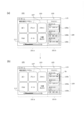
- FIG. 7 shows the main screen 101 in the second embodiment.
- FIG. 7 shows the main screen after user authentication, and the user name 117 is displayed in the title bar 115.
- FIG. 8 shows the sub-screen 121 in the second embodiment.
- FIG. 8 is a diagram showing an example of a sub-screen (copy) transitioned from the main screen of FIG.
- the identification information that identifies the user may be, for example, the "user name" shown as the image processing information in the description of the first embodiment.
- the user name was used as information displayed for the user to identify or confirm history button 109 .
- the image data to which access is permitted differs and the history button 109 to be displayed differs depending on the user who logs in to the image processing apparatus 1 .
- User name may be a character string set by the user or the administrator of the image processing apparatus 1, for example.
- the image processing apparatus 1 may assign another type of identification information to the user name and associate and store both of them, thereby performing a database search or the like using the other type of identification information. That is, the identification information (user name) used externally may be different from the identification information used internally. However, both can be regarded as being conceptually the same, so in the description of the present embodiment, the user name is also used internally.
- Authentication is performed by determining whether or not a user attempting to use the image processing apparatus 1 (attempting to log in to the image processing apparatus 1) is a pre-registered user (from another point of view, a user corresponding to a user name). This is an operation to confirm.
- the authentication method may be various methods, for example, a known method.
- authentication may be performed by entering a user name and password via the operation panel 9.
- this aspect is mainly taken as an example.
- the authentication may be biometric authentication performed based on the user's biometric information detected by a detection unit (not shown) of the image processing apparatus 1 .
- Biometric information includes, for example, a fingerprint or an iris.
- the authentication may be card authentication performed based on communication between a card reader (not shown) of the image processing apparatus 1 and the user's IC (Integrated Circuit) card.
- Card authentication may be static authentication or dynamic authentication.
- Authentication may also be performed based on information read from a storage medium (for example, a USB memory) connected to a connector (not shown) of the image processing apparatus 1 . Further, for example, authentication may be performed based on communication between the communication unit 7 of the image processing apparatus 1 and a terminal (for example, a mobile terminal) owned by the user.
- a storage medium for example, a USB memory
- a terminal for example, a mobile terminal
- authentication methods other than authentication via the communication unit 7 are performed by a user interface unit (for example, the operation panel 9, a detection unit for detecting biometric information, It can be said that authentication is performed by a user's input action to a card reader or connector).
- the input of the user name can be omitted in the authentication methods other than the password-based authentication.
- a substantial part of authentication may be performed by the image processing apparatus 1 itself (authentication management section), for example.
- the image processing apparatus 1 may transmit authentication information to a server (not shown) via the communication unit 7, have the server perform verification, and use the result to grant authorization to the user. . That is, the image processing apparatus 1 (authentication management unit) may grant authority based on the result of user authentication, and does not need to perform user authentication itself.
- At least part of the authentication management unit may be constructed by executing a program stored in the storage unit 13 by the CPU 11, or may be regarded as part of the control unit described above.
- the user name and authentication information are associated with each other in the database of the image processing apparatus 1 (or server) in advance, for example, by the operation of the administrator of the image processing apparatus 1 or individual users. stored. Then, when the user performs an operation for authentication, the image processing apparatus 1 performs authentication by referring to the database.
- the history display area 121b of the sub-screen 121 a user authorized by the authentication management unit (user name "xxxx” in FIG. 8) has completed past image processing. Only the history button is displayed. That is, when the "copy" function button 107 is selected on the main screen 101 after user authentication, on the sub-screen 121 after transition, the history button is displayed specifically for the history of "copy” completed by the user in the past. 134 is displayed. With this configuration, it is possible to further improve the convenience of searching for the history button that the user needs.
- the third embodiment relates to fixed display (preferential display) of the history button 109 on the main screen 101 and the history button 134 on the sub-screen 121 .
- Fixed display is, for example, when a plurality of history buttons 109 (or 134) are displayed, a specific history button 109 (or 134) is arranged and displayed at the top.
- the specific history button 109 when a specific history button 109 is fixedly displayed on the main screen 101, the specific history button 109 is also displayed on the sub-screen 121 (history button 109 on the sub-screen 121). button 134) is fixedly displayed.
- a specific history button 134 when a specific history button 134 is set to be fixedly displayed on the sub-screen 121, the specific history button 134 (the history button 109 on the main screen 101 and the history button 109 on the main screen 101) ) is fixedly displayed.
- a plurality of history buttons 109a, 109b and 109c are displayed on the main screen 101.
- the history button 109c can be fixedly displayed.
- the history button 109c set to be displayed fixedly is arranged at the top.
- the history button 109c (shown as history button 134c on the sub-screen 121) set to be fixedly displayed on the main screen 101 is fixedly displayed.
- the fixed display setting made on the main screen 101 is also reflected on the sub-screen 121, thereby improving the user's convenience.
- a plurality of history buttons 134a, 134c and 134d are displayed on the sub-screen 121.
- the history button 134c can be fixedly displayed.
- the history button 109c set to be displayed fixedly is arranged at the top.
- the history button 134c (indicated as the history button 109c on the main screen 101) set to be fixedly displayed on the sub-screen 121 is fixedly displayed.
- the fixed display setting made on the sub-screen 121 is also reflected on the main screen 101, thereby improving the user's convenience.
- the corresponding history button is automatically fixedly displayed on the other screen.
- the fixed display is, for example, on either one of the main screen 101 and the sub-screen 121 (it may be a screen on which fixed display is set, or may be a screen on which fixed display is automatically performed). It is maintained until the fixed display setting is canceled. That is, it is maintained even if the transition between the main screen 101 and the sub-screen 121 is repeated. When the fixed display setting is canceled on one of the screens, the fixed display on the other screen is automatically disabled.
- the history button 109 or 134 is set to be fixedly displayed on the main screen 101 or the sub screen 121, a sub screen corresponding to image processing (such as FAX) different from the image processing (such as copy) corresponding to the history button is displayed.
- image processing such as FAX
- copy which is set to be displayed fixedly, need not be displayed on the subscreen 121 (FAX).
- FIG. 13 shows an example of the main screen 101 at this time.
- a history button 109f corresponding to image processing newly performed on the sub-screen 121 (FAX) is added to the main screen 101 of FIG.
- the history button 109c is fixedly displayed as in the main screen 101 of FIG.
- the "copy" function button 107 is selected on the main screen 101, the history button 134c is fixedly displayed (see FIG. 10) as in the operation already described.
- the fixed display may be settable for only one history button 109 (134), or may be settable for any number of history buttons.
- the upper limit of the number of history buttons fixedly displayed may be, for example, less than or less than the number of history buttons that can be displayed in the history display area 101b or 121b.
- the types of images corresponding to a plurality of history buttons set to be displayed fixedly may be different from each other.
- FIG. 14 shows an example of the screen when the screen is returned to the main screen 101 after performing the above.
- the history button 109g whose fixed display is newly set is displayed following the history button 109c whose fixed display was previously set. 14, it is assumed that image processing corresponding to the history button 109f shown in FIG. 13 is not performed on the sub-screen 121 of FIG.
- the fixed display may be in various forms other than the form displayed at the top of the plurality of history buttons.
- fixed display means that, for example, a specific history button 109 or 134 is displayed in the history display area 101b of the main screen 101 or the history display area 121b of the sub-screen 121 (not the history area 105 or 135). ), it can be said that it is displayed at a fixed position or that the user can recognize it as such.
- a particular history button is displayed at the top or bottom of the row.
- the above "fixed position” may be the same for the history display areas 101b and 121b, for example.
- the “fixed position” does not necessarily have to be a strictly fixed position, and may be such a position that is “recognizable by the user”. For example, as in the typical example above, in both history display areas 101b and 121b, if the head or tail of a plurality of display positions to which a plurality of history buttons are distributed is set as a fixed display position, history display Even if there is some positional deviation between the areas 101b and 121b, and the number of history buttons that can be displayed is different between the history display areas 101b and 121b, there is no practical problem. Note that, unlike the description here, the "fixed position” may be different between the history display areas 101b and 121b. Also, the "fixed position” does not have to be the leading or trailing position, and may be, for example, the central position.
- the direction of the row of history buttons is arbitrary and is not limited to the vertical direction.
- the above "top or bottom” is replaced with "display positions of two or more history buttons that are continuous including the top or bottom”. good.
- the order of the two or more history buttons that are fixedly displayed may be set as appropriate, for example, the order in which the fixed display is set, the chronological order (oldest first or newest first), the order set by the user, or the image The order may be determined according to the type of processing.
- the operation for setting and canceling the fixed display may be done as appropriate. For example, as mentioned in Section 1.3.2, an operation (e.g. long tap or double tap) different from the operation (e.g. tap) when using the history information corresponding to the history button is performed on the history button. By doing so, the setting of the fixed display (if the fixed display has already been set, the setting is cancelled) may be performed.
- an operation e.g. long tap or double tap
- the operation e.g. tap
- the history button 109 or 134 When the history button 109 or 134 is fixedly displayed, information indicating that the history button is fixedly displayed may be displayed.
- the history button is fixedly displayed by displaying the symbol image Sy in the shape of a pin inside the history button.
- the history button frame and/or the color inside the history button that is fixedly displayed and other history buttons different, or by making the shape of the frame different The presence or absence may be indicated.
- the fixed display may be canceled by a condition (for example, login of a new user) different from an operation that directly instructs the cancellation.
- a condition for example, login of a new user
- fixed display setting and cancellation may be performed separately for the main screen 101 and the sub-screen 121, or fixed display setting may be performed for the main screen 101 and the sub-screen 121. , while the release may be performed separately.
- Area (a) in FIG. 15 shows the sub-screen 121 when "fax" is selected on the main screen 101.
- Area (b) in FIG. 15 shows the sub-screen 121 with "000-000-1111” entered in “destination”.
- "000-000-1111” in “destination” By inputting "000-000-1111” in “destination”, only the history buttons 134a, 134d and 134e with the destination "000-000-1111” are displayed in the history display area 121b.
- the history buttons 134 By displaying only the history buttons 134 related to the input "destination", the history buttons 134 are narrowed down and the user's convenience is improved.
- Area (a) in FIG. 16 shows the sub-screen 121 when "Mail" is selected on the main screen 101.
- FIG. On the sub-screen 121, there are a history button 134a with an address of "xxx@xx.com”, a history button 134b with an address of "yyy@yy.com”, and a history button 134c with an address of "zzz@zz.com”. is displayed.
- Area (b) in FIG. 16 shows the sub-screen 121 with "xxx@xx.com” entered in “destination”.
- the history buttons 134 are narrowed down and the user's convenience is improved.
Landscapes
- Engineering & Computer Science (AREA)
- General Engineering & Computer Science (AREA)
- Theoretical Computer Science (AREA)
- Multimedia (AREA)
- Signal Processing (AREA)
- Human Computer Interaction (AREA)
- Physics & Mathematics (AREA)
- General Physics & Mathematics (AREA)
- Facsimiles In General (AREA)
Abstract
This image processing device comprises an operation panel. In the operation panel, a main screen and a sub screen can be displayed. The main screen has a menu region in which a plurality of function buttons corresponding to the types of image processing are arranged. The sub screen has a reception region which is transitioned from the main screen after one of the function buttons is selected, and receives an instruction for image processing pertaining to the selected function button. In the sub screen, a history display region, which displays a plurality of history buttons that include information about image processing completed in the past, specialized for the image processing corresponding to the function button being selected, is displayed side by side with the reception region.
Description
本開示は、画像処理装置に関する。画像処理とは画像の取り扱いに関する各種処理のことであり、例えば、画像の印刷、画像のスキャン、画像ファイルの送信・受信等である。
The present disclosure relates to an image processing device. Image processing refers to various types of processing related to image handling, such as image printing, image scanning, and image file transmission/reception.
画像処理の履歴を表示可能な画像処理装置が知られている(例えば下記特許文献1)。例えば、特許文献1の画像処理装置は、画像処理の履歴に関する複数のボタン(履歴ボタン)を画像処理の実行日時の順に並べて操作パネルに表示する。各履歴ボタンは、画像処理の種別(コピー、スキャン等)、画像処理の条件(部数、カラーまたはモノクロ印刷、片面・両面印刷等)及び画像処理の実行日時を表示する。いずれかの履歴ボタンがタッチパネル付きの操作パネルを介して選択されると、その履歴ボタンに対応する画像処理の条件が、これから行われる画像処理の条件として設定される。これにより、過去に設定した条件を簡便に利用することができる。
An image processing device capable of displaying the history of image processing is known (for example, Patent Document 1 below). For example, the image processing apparatus disclosed in Patent Document 1 displays a plurality of buttons (history buttons) related to the history of image processing arranged in order of execution date and time of the image processing on the operation panel. Each history button displays the type of image processing (copy, scan, etc.), image processing conditions (number of copies, color or monochrome printing, single-sided/double-sided printing, etc.), and execution date and time of image processing. When any history button is selected via the operation panel with a touch panel, the image processing conditions corresponding to that history button are set as the conditions for image processing to be performed from now on. Thereby, the conditions set in the past can be easily used.
本開示の一態様に係る画像処理装置は所定の表示形態を実現可能な操作パネルを備える。前記操作パネルは、メイン画面とサブ画面とが表示可能とされている。前記メイン画面は、画像処理の種別に対応した複数の機能ボタンが配列されているメニュー領域を有している。前記サブ画面は、前記機能ボタンの1つを選択した後に前記メイン画面より遷移して、選択中の機能ボタンに関する画像処理の指示を受け付ける受付領域を有している。前記サブ画面には、選択中の機能ボタンに対応した画像処理に特化して過去に完了した画像処理の情報を含む複数の履歴ボタンを表示する第1の履歴表示領域が、前記受付領域と並んで表示される。
An image processing apparatus according to one aspect of the present disclosure includes an operation panel capable of realizing a predetermined display form. The operation panel is capable of displaying a main screen and a sub-screen. The main screen has a menu area in which a plurality of function buttons corresponding to types of image processing are arranged. The sub-screen has a reception area that transitions from the main screen after one of the function buttons is selected and receives an image processing instruction for the selected function button. In the sub-screen, a first history display area displaying a plurality of history buttons including information on image processing completed in the past, specialized for image processing corresponding to the selected function button, is arranged side by side with the reception area. is displayed.
(画像処理装置の概要)
図1は実施形態に係る画像処理装置1の外観図であり、図2は画像処理装置1の構成を示すブロック図である。 (Overview of image processing device)
FIG. 1 is an external view of animage processing device 1 according to an embodiment, and FIG. 2 is a block diagram showing the configuration of the image processing device 1. As shown in FIG.
図1は実施形態に係る画像処理装置1の外観図であり、図2は画像処理装置1の構成を示すブロック図である。 (Overview of image processing device)
FIG. 1 is an external view of an
画像処理装置1は、複合機として構成されており、例えば、以下の構成を備えている。印刷を行うプリンタ3。画像の読み取りを行うスキャナ5。外部と通信を行う通信部7。ユーザーの操作を受け付ける操作パネル9。種々の演算を行うCPU11(Central Processing Unit)。種々の情報を記憶する記憶部13。これらの構成を保持する筐体15。
The image processing apparatus 1 is configured as a multifunction device, and has, for example, the following configuration. Printer 3 for printing. A scanner 5 for reading an image. A communication unit 7 that communicates with the outside. An operation panel 9 for accepting user operations. A CPU 11 (Central Processing Unit) that performs various calculations. A storage unit 13 that stores various information. A housing 15 that holds these configurations.
操作パネル9は、筐体15の上部に設けられており、タッチパネルを含んでいる。操作パネル9は、物理ボタン等のタッチパネル以外の操作対象を含んでいてもよい。ただし、実施形態の説明では、操作パネル9がタッチパネルのみによって構成されている態様を前提とした表現をすることがある。
The operation panel 9 is provided on the top of the housing 15 and includes a touch panel. The operation panel 9 may include operation targets other than the touch panel, such as physical buttons. However, in the description of the embodiment, expressions may be made assuming that the operation panel 9 is composed only of a touch panel.
図3は、操作パネル9に表示されるメイン画面101の一例を示す図である。ここでは、メイン画面101として、ホーム画面を例として示している。
FIG. 3 is a diagram showing an example of the main screen 101 displayed on the operation panel 9. FIG. Here, a home screen is shown as an example of the main screen 101 .
メイン画面101は、例えば、ユーザーが画像処理装置1の利用を開始するときや待機状態のときに表示されている画面である。別の観点では、メイン画面101は、画像処理装置1に電源が投入されたとき、画像処理装置1がスリープモードから復帰したとき、及び/又は画像処理装置1においてユーザーの認証が成功したときに、立ち上げられる画面である。
The main screen 101 is, for example, a screen that is displayed when the user starts using the image processing apparatus 1 or is in a standby state. From another point of view, the main screen 101 is displayed when the image processing apparatus 1 is powered on, when the image processing apparatus 1 returns from the sleep mode, and/or when user authentication is successful in the image processing apparatus 1. , is the screen that is launched.
メイン画面101は、例えば、メニュー領域101aと、履歴表示領域(タイムライン表示領域)101bとが並んで表示される。メニュー領域101aは、メイン領域103のうちの一部領域を表示する。上記一部領域がメイン領域103に占める範囲は、スクロールバー111によって示されてよい。また、履歴表示領域101bは、履歴領域(タイムライン領域)105のうちの一部領域を表示する。上記一部領域が履歴領域105に占める範囲は、スクロールバー113によって示されてよい。
On the main screen 101, for example, a menu area 101a and a history display area (timeline display area) 101b are displayed side by side. The menu area 101 a displays a partial area of the main area 103 . The range occupied by the partial area in the main area 103 may be indicated by a scroll bar 111 . A history display area 101 b displays a partial area of the history area (timeline area) 105 . The range occupied by the partial area in history area 105 may be indicated by scroll bar 113 .
メニュー領域101a(メイン領域103)には、画像処理の種別に対応した複数の機能ボタン107が配列されている。複数の機能ボタン107は、互いに異なる機能(別の観点では画像処理)からいずれか1つの機能を選択するためのものである。機能ボタン107は、自己に対応する機能の情報を表示している。図3では、機能として、「コピー」、「プリント」、「スキャン」、「FAX(ファックス)」(facsimile)、「メール」及び「文書ボックス」が例示されている。いずれかの機能ボタン107に対して所定の操作(例えば1回のタッチ(例えばタップ))がなされると、例えば、操作パネル9に表示される画面は、その機能ボタン107に対応する機能に係る操作を行うための画面(サブ画面121(例えば図4))に切り換わる。すなわち、メイン画面101で機能ボタン107の1つを選択した後、メイン画面101は、サブ画面121へ遷移する。機能に係る操作は、例えば、画像処理を実行する操作、及び画像処理の条件(例えばコピーを行うときの用紙の大きさ等)を設定する操作である。
A plurality of function buttons 107 corresponding to the types of image processing are arranged in the menu area 101a (main area 103). A plurality of function buttons 107 are for selecting any one function from mutually different functions (image processing from another point of view). The function button 107 displays information on the function corresponding to itself. In FIG. 3, "copy", "print", "scan", "FAX" (facsimile), "mail" and "document box" are illustrated as functions. When a predetermined operation (for example, one touch (for example, tap)) is performed on any function button 107, for example, the screen displayed on the operation panel 9 changes to the function corresponding to that function button 107. Switches to a screen (sub-screen 121 (eg, FIG. 4)) for performing an operation. That is, after selecting one of the function buttons 107 on the main screen 101 , the main screen 101 transitions to the sub-screen 121 . The operation related to the function is, for example, an operation of executing image processing and an operation of setting image processing conditions (for example, the size of paper for copying).
履歴領域105は、複数の履歴ボタン109を有している。各履歴ボタン109は、過去に行われた画像処理(機能)に関する情報を含んでいる(表示している)。図3では、履歴ボタン109に表示される画像処理の情報として、画像処理が実行された日時と、画像処理の種別(図3では「コピー」、「FAX」又は「メール」が例示)と、画像処理の条件(図3では「カラー」・「白黒」等が例示)とが例示されている。その他、履歴ボタン109には、通信先(以下、宛先ともいう)が表示される場合もある。いずれかの履歴ボタン109に対して所定の操作(例えば1回のタッチ(例えばタップ))がなされると、操作パネル9に表示される画面は、例えば、その履歴ボタン109に対応する履歴情報を利用するための履歴利用画面(不図示)に切り換わる。
The history area 105 has a plurality of history buttons 109. Each history button 109 contains (displays) information about image processing (functions) performed in the past. In FIG. 3, the image processing information displayed on the history button 109 includes the date and time when the image processing was executed, the type of image processing ("copy", "fax", or "mail" is exemplified in FIG. 3), Image processing conditions ("color", "black and white", etc. are exemplified in FIG. 3). In addition, the history button 109 may display a communication destination (hereinafter also referred to as a destination). When a predetermined operation (eg, one touch (eg, tap)) is performed on any of the history buttons 109, the screen displayed on the operation panel 9 displays, for example, history information corresponding to the history button 109. Switches to a history use screen (not shown) for use.
図4は、操作パネル9に表示されるサブ画面121の一例を示す図である。より詳細には、図3に例示された6つの機能ボタン107のうち、「コピー」の機能ボタン107が選択された場合のサブ画面121の一例が示されている。サブ画面121は、選択された機能ボタン107に対応する画像処理に関する画面である。サブ画面121は、選択中の機能ボタン107に関する画像処理の指示を受け付ける受付領域121aと、選択中の機能ボタン107に対応した画像処理に特化して過去に完了した画像処理の情報を含む複数の履歴ボタン134を含む履歴表示領域121bとが、並んで表示される。履歴表示領域121bは、履歴領域(タイムライン領域)135のうちの一部領域を表示する。上記一部領域が履歴領域135に占める範囲はスクロールバー123によって示されてよい。
FIG. 4 is a diagram showing an example of the sub-screen 121 displayed on the operation panel 9. FIG. More specifically, an example of the sub-screen 121 when the "copy" function button 107 is selected from the six function buttons 107 illustrated in FIG. 3 is shown. The subscreen 121 is a screen regarding image processing corresponding to the selected function button 107 . The sub-screen 121 includes a reception area 121a for receiving an image processing instruction for the currently selected function button 107, and a plurality of screens including information on previously completed image processing specialized for image processing corresponding to the currently selected function button 107. A history display area 121b including a history button 134 is displayed side by side. The history display area 121 b displays a partial area of the history area (timeline area) 135 . The range occupied by the partial area in history area 135 may be indicated by scroll bar 123 .
画像処理装置1は、ユーザー(特に断りが無い限り、また、矛盾等が生じない限り、ユーザーグループを含むものとする。以下、同様。)を識別する機能(さらにはユーザーを認証する機能)を有していてもよいし、有していなくてもよい。説明を簡便にするために、便宜上、そのような識別機能及び認証機能の有無を問わない態様を第1実施形態と称し、認証機能を前提とする態様を第2実施形態と称し、順に説明する。ただし、便宜上、第1実施形態の説明においても、画像処理装置1がユーザーを識別(さらには認証)する機能を有していることが前提となる情報、構成及び動作について、言及することがある。
The image processing apparatus 1 has a function of identifying a user (and a function of authenticating a user) (unless otherwise specified or contradictory, user groups are included; the same shall apply hereinafter). It may or may not have In order to simplify the explanation, for the sake of convenience, the aspect that does not require such an identification function and the authentication function will be referred to as the first embodiment, and the aspect that assumes the authentication function will be referred to as the second embodiment, and will be described in order. . However, for the sake of convenience, the description of the first embodiment may also refer to information, configurations, and operations on the premise that the image processing apparatus 1 has a function of identifying (and authenticating) a user. .
<第1実施形態>
以下では、第1実施形態に係る画像処理装置1について、概略、下記の順に説明する。
1.1.用語等について
1.2.画像処理装置1の構成(図1及び図2)
1.3.メイン画面101に係る画像処理装置1の動作(図3)
1.4.サブ画面121に係る画像処理装置1の動作(図4~図6) <First embodiment>
Theimage processing apparatus 1 according to the first embodiment will be described below in the following order.
1.1. Terminology 1.2. Configuration of image processing apparatus 1 (FIGS. 1 and 2)
1.3. Operation of theimage processing apparatus 1 related to the main screen 101 (FIG. 3)
1.4. Operation of theimage processing apparatus 1 related to the sub screen 121 (FIGS. 4 to 6)
以下では、第1実施形態に係る画像処理装置1について、概略、下記の順に説明する。
1.1.用語等について
1.2.画像処理装置1の構成(図1及び図2)
1.3.メイン画面101に係る画像処理装置1の動作(図3)
1.4.サブ画面121に係る画像処理装置1の動作(図4~図6) <First embodiment>
The
1.1. Terminology 1.2. Configuration of image processing apparatus 1 (FIGS. 1 and 2)
1.3. Operation of the
1.4. Operation of the
(1.1.用語等について)
「画像」は、文字のみを含むものであっても構わない。「画像データ」の形式は、種々のものとされてよく、例えば、ベクター形式であってもよいし、ラスター形式であってもよい。実施形態の説明では、便宜上、「画像」と「画像データ」とを厳密に区別しないことがある。 (1.1. Terminology)
An "image" may include only characters. The "image data" may be in various formats, such as vector format or raster format. In the description of the embodiments, for the sake of convenience, "image" and "image data" may not be strictly distinguished.
「画像データ」は、画像処理が行われる過程において、適宜に形式の変換が行われてよい。例えば、画像データは、画像処理装置1に記憶されているときと、画像処理(例えば印刷、スキャン、FAX、画像ファイルの送信・受信等)が行われるときとで異なっていてよい。ただし、実施形態の説明では、便宜上、そのような形式の変換についての説明は省略し、変換前後の画像データを同一のものとして説明することがある。また、画像データは、画像処理が行われるときなどにおいて、画質が変化したり、画像の一部が切り出されたりするような変更が加えられてもよい。このような場合も、実施形態の説明では、便宜上、変更前後の画像データを区別しないことがある。
"Image data" may be appropriately converted in format in the process of image processing. For example, the image data stored in the image processing apparatus 1 may differ from the image data when image processing (for example, printing, scanning, facsimile, transmission/reception of image files, etc.) is performed. However, in the description of the embodiment, for the sake of convenience, the description of such format conversion may be omitted, and the image data before and after conversion may be described as being the same. Further, the image data may be changed such that the image quality is changed or a part of the image is cut out when image processing is performed. Even in such a case, the image data before and after the change may not be distinguished in the description of the embodiment for the sake of convenience.
操作パネル9の種々の画面の種々の部位(例えば、履歴ボタン109、134)に表示される情報は、例えば、テキストによって表示されてもよいし、及び/又はシンボル画像によって表示されてもよい。実施形態の説明において、例えば、操作パネル9に情報が表示される、又は操作パネル9に表示されている部位(ボタン等)が情報を含むというとき、特に矛盾等が生じない限り、上記情報は、テキスト及び/又はシンボル画像によって表示されてよいものとする。情報が表示される部位としては、例えば、履歴ボタン109、134の他、機能ボタン107、実行ボタン125、設定ボタン131(後述)、戻るボタン133(後述)、これらのボタンの周囲の領域、並びにタイトルバー115及び127(後述)が挙げられる。
Information displayed on various parts of various screens of the operation panel 9 (for example, the history buttons 109 and 134) may be displayed by text and/or by symbol images, for example. In the description of the embodiments, for example, when information is displayed on the operation panel 9 or a portion (such as a button) displayed on the operation panel 9 includes information, the information is , text and/or symbol images. Information is displayed on, for example, history buttons 109 and 134, function button 107, execution button 125, setting button 131 (described later), return button 133 (described later), areas around these buttons, and Title bars 115 and 127 (discussed below) are included.
「テキスト」は、例えば、文字列として表示される情報、及び/又はテキストデータに基づいて表示される情報を指してよい。従って、例えば、テキストは、画像データに基づいて表示される文字列であってもよいし、テキストデータに基づいて表示される記号又は1つのみの文字であってもよい。「シンボル画像」は、例えば、記号又は図形等として表示される情報、及び/又は画像データに基づいて表示される情報を指してよい。従って、例えば、シンボル画像は、テキストデータに基づいて表示される記号であってもよいし、画像データに基づいて表示される1以上の文字であってもよい。上記の説明から理解されるように、テキストとシンボル画像とは一部が重複した分類であって構わない。
"Text" may refer to, for example, information displayed as a character string and/or information displayed based on text data. Thus, for example, the text may be a character string displayed based on image data, or a symbol or only one character displayed based on text data. A “symbol image” may refer to information displayed as, for example, a symbol or graphic, and/or information displayed based on image data. Therefore, for example, the symbol image may be a symbol displayed based on text data, or one or more characters displayed based on image data. As can be understood from the above description, text and symbol images may be partially overlapping classifications.
操作パネル9に表示される「ボタン」は、物理ボタンを模したものでなくてよい。例えば、ボタンは、テキスト及び/又はシンボル画像によってのみ示され、テキスト及び/又はシンボル画像を囲む枠線を有していなくてもよい。また、別の観点では、例えば、ユーザーの操作を検出する領域と、その周囲の領域との境界は、枠線又は色の相違によって表現されていなくてもよい。
The "buttons" displayed on the operation panel 9 do not have to imitate physical buttons. For example, a button may only be represented by text and/or symbolic images and not have a border surrounding the text and/or symbolic images. Also, from another point of view, for example, the boundary between the region where the user's operation is detected and the surrounding region may not be represented by a frame line or different colors.
実施形態の説明では、便宜上、操作パネル9に対する操作について、「タップ」、「ダブルタップ」及び「ロングタップ」等の具体的な態様を示す用語を用いることがある。ただし、これらの用語は、「所定の操作」と上位概念化されてよい。
In the description of the embodiments, terms such as "tap", "double tap", and "long tap" may be used for the operation of the operation panel 9 for convenience. However, these terms may be generalized as "predetermined operation".
(1.2.画像処理装置の構成)
図1および図2に示す画像処理装置1は、操作パネル9を有しているとともに、1種以上の画像処理を行うことが可能な構成を有している。その具体的な構成は、種々の構成とされてよく、例えば、公知の構成とされても構わない。本実施形態では、画像処理を行うための構成として、既述のように、プリンタ3、スキャナ5及び通信部7が設けられている。本実施形態とは異なる態様としては、例えば、プリンタ3及びスキャナ5の一方のみを有する態様、及び通信部7を有していない態様が挙げられる。また、画像処理装置1の各部(3、5、7、9、11及び13)の構成も、種々の構成とされてよく、例えば、公知の構成とされても構わない。 (1.2. Configuration of image processing apparatus)
Theimage processing apparatus 1 shown in FIGS. 1 and 2 has an operation panel 9 and a configuration capable of performing one or more types of image processing. The specific configuration may be various configurations, for example, it may be a known configuration. In this embodiment, the printer 3, the scanner 5, and the communication section 7 are provided as a configuration for performing image processing, as described above. Aspects different from the present embodiment include, for example, a aspect in which only one of the printer 3 and the scanner 5 is provided, and an aspect in which the communication section 7 is not provided. Also, the configuration of each unit (3, 5, 7, 9, 11 and 13) of the image processing apparatus 1 may be of various configurations, for example, may be a known configuration.
図1および図2に示す画像処理装置1は、操作パネル9を有しているとともに、1種以上の画像処理を行うことが可能な構成を有している。その具体的な構成は、種々の構成とされてよく、例えば、公知の構成とされても構わない。本実施形態では、画像処理を行うための構成として、既述のように、プリンタ3、スキャナ5及び通信部7が設けられている。本実施形態とは異なる態様としては、例えば、プリンタ3及びスキャナ5の一方のみを有する態様、及び通信部7を有していない態様が挙げられる。また、画像処理装置1の各部(3、5、7、9、11及び13)の構成も、種々の構成とされてよく、例えば、公知の構成とされても構わない。 (1.2. Configuration of image processing apparatus)
The
画像処理装置1は、例えば、既述の種々の構成要素(3、5、7、9、11及び13)を収容している筐体15を有している。画像処理装置1(別の観点では筐体15)の大きさ及び形状は任意である。例えば、画像処理装置1は、家庭用の複合機又はプリンタのように1人の人間が運搬可能な大きさ(質量)を有していてもよいし、業務用の複合機又はプリンタのように1人の人間が運搬不可能な大きさ(質量)を有していてもよい。
The image processing apparatus 1 has, for example, a housing 15 housing the various components (3, 5, 7, 9, 11 and 13) described above. The size and shape of the image processing device 1 (or housing 15 from another point of view) are arbitrary. For example, the image processing apparatus 1 may have a size (mass) that can be carried by one person, such as a multifunction machine or printer for home use, or a multifunction machine or printer for business use. A single person may have an unportable size (mass).
画像処理装置1の運用方法(別の観点では社会的位置付け)は任意である。例えば、画像処理装置1は、家に置かれて、家庭的又は個人的に利用されてもよいし、会社に置かれて、特定かつ複数のユーザーに利用されてもよいし、コンビニエンスストア等の店舗に置かれて、不特定多数のユーザーに利用されてもよい。なお、不特定多数のユーザーが利用することを想定する場合、画像処理装置1は、ユーザーを認証して、そのユーザーに係る画像データにのみアクセスを許可してよい。
The operation method of the image processing device 1 (social positioning from another point of view) is arbitrary. For example, the image processing apparatus 1 may be placed at home for home or personal use, may be placed at a company for use by a specific number of users, or may be placed at a convenience store or the like. It may be placed in a store and used by an unspecified number of users. Note that if it is assumed that an unspecified number of users will use the image processing apparatus 1, the image processing apparatus 1 may authenticate the user and permit access only to the image data related to that user.
プリンタ3の構成は任意である。例えば、プリンタ3は、不図示のトレイに配置された用紙(別の観点では枚葉紙)に印刷を行い、印刷後の用紙を排出するように構成されてよい。プリンタ3は、1つのトレイのみを有していてもよいし、複数のトレイを有していてもよい。複数のトレイは、例えば、異なるサイズの用紙を収容することに寄与する。別の観点では、プリンタ3は、用紙のサイズを選択する機能を有していてもよいし、有していなくてもよい。なお、本実施形態の説明では、前者を例に取る。また、プリンタ3は、カラー(並びにモノクロ及びグレースケール)の印刷が可能な構成であってもよいし、グレースケール(及びモノクロ)の印刷のみが可能な構成であってもよいし、モノクロの印刷のみが可能な構成であってもよい。なお、本実施形態の説明では、カラーの印刷が可能な構成を例に取る。
The configuration of the printer 3 is arbitrary. For example, the printer 3 may be configured to print on paper (sheet paper from another point of view) arranged in a tray (not shown) and to discharge the printed paper. The printer 3 may have only one tray, or may have multiple trays. Multiple trays, for example, help accommodate different size sheets. From another point of view, the printer 3 may or may not have the function of selecting the paper size. Note that the former will be taken as an example in the description of the present embodiment. Further, the printer 3 may be configured to perform color (and monochrome and grayscale) printing, may be configured to perform only grayscale (and monochrome) printing, or may be configured to perform monochrome printing. It may be a configuration in which only Note that in the description of the present embodiment, a configuration capable of color printing is taken as an example.
また、例えば、プリンタ3は、インクを吐出して印刷を行うインクジェットプリンタであってもよいし、感熱紙又はインクリボンを加熱して印刷を行うサーマルプリンタであってもよいし、光が照射された感光体に付着したトナーを転写する電子写真式プリンタ(例えばレーザープリンタ)であってもよい。インクジェットプリンタは、圧電体によってインクに圧力を付与するピエゾ式であってもよいし、熱が付与されたインクに生じる気泡によってインクに圧力を付与するサーマル式であってもよい。また、例えば、プリンタ3は、ヘッドが用紙の幅(用紙の搬送方向に交差する方向)に亘る長さを有するラインプリンタであってもよいし、ヘッドが用紙の幅方向に移動するシリアルプリンタであってもよい。
Further, for example, the printer 3 may be an inkjet printer that prints by ejecting ink, or a thermal printer that prints by heating thermal paper or an ink ribbon. It may also be an electrophotographic printer (for example, a laser printer) that transfers toner adhering to a photoreceptor. The inkjet printer may be of the piezo type in which pressure is applied to the ink by a piezoelectric body, or may be of the thermal type in which pressure is applied to the ink by air bubbles generated in the ink to which heat is applied. Further, for example, the printer 3 may be a line printer having a head that spans the width of the paper (a direction crossing the paper transport direction), or a serial printer in which the head moves in the width direction of the paper. There may be.
スキャナ5は、例えば、特に図示しないが、原稿ガラス下にて原稿ガラスに沿って移動する複数の撮像素子によって原稿ガラス上に配置された原稿を撮像してスキャンを行う。
For example, although not shown, the scanner 5 captures and scans an original placed on the original glass with a plurality of imaging elements that move along the original glass under the original glass.
通信部7は、画像処理装置1と他の機器との通信を実現する。他の機器としては、例えば、パーソナルコンピュータ(PC)、携帯端末(スマートフォン等)、他の画像処理装置及びサーバが挙げられる。サーバとしては、例えば、ファイルサーバ、メールサーバ及びWebサーバが挙げられる。通信は、他の機器と直接的に行われるものであってもよいし、ネットワークを介して間接的に行われるものであってもよい。ネットワークとしては、例えば、電話網、インターネット、プライベートネットワーク及びLAN(Local Area Network)が挙げられる。また、通信は、有線通信であってもよいし、無線通信であってもよいし、近距離通信であってもよいし、遠距離通信であってもよい。
The communication unit 7 realizes communication between the image processing device 1 and other devices. Other devices include, for example, personal computers (PCs), mobile terminals (smartphones, etc.), other image processing devices, and servers. Examples of servers include file servers, mail servers, and web servers. Communication may be performed directly with another device, or may be performed indirectly via a network. Networks include, for example, telephone networks, the Internet, private networks, and LANs (Local Area Networks). Communication may be wired communication, wireless communication, short-range communication, or long-distance communication.
画像処理装置1は、上記のような種々の通信のうち、1以上の任意の通信が可能に構成されてよい。本実施形態の説明では、画像処理装置1が、上記のような種々の通信を可能である態様を例に取る。通信部7は、特に図示しないが、上記のような種々の通信を実現するための種々の構成要素を含んでいる。通信部7は、ハードウェア的な構成(例えば、コネクタ、アンテナ、増幅器、フィルタ、RF(Radio Frequency)回路)のみを含むと捉えられてもよいし、ハードウェア的な構成に加えて、ソフトウェア的な構成(CPUがプログラムを実行することによって構築される機能部)を含むと捉えられてもよい。
The image processing apparatus 1 may be configured to allow any one or more of the various communications described above. In the description of the present embodiment, the image processing apparatus 1 is exemplified by a mode capable of various communications as described above. Although not shown, the communication unit 7 includes various components for realizing various communications as described above. The communication unit 7 may be regarded as including only hardware configuration (for example, connector, antenna, amplifier, filter, RF (Radio Frequency) circuit), or in addition to the hardware configuration, software configuration (a functional unit constructed by a CPU executing a program).
操作パネル9は、既述のように、タッチパネルを含んでいる。タッチパネルは、特に図示しないが、表示装置と、表示装置の画面に重なる位置入力装置とを有している。表示装置及び位置入力装置の構成は任意である。
The operation panel 9 includes a touch panel as described above. Although not shown, the touch panel has a display device and a position input device that overlaps the screen of the display device. The configuration of the display device and the position input device is arbitrary.
例えば、表示装置は、液晶ディスプレイ又は有機EL(Electro Luminescence)ディスプレイによって構成されてよい。これらのディスプレイは、規則的に配列された比較的多数の画素を有しており、画像データに基づいて任意の形状を含む画像を表示可能である。表示装置は、カラー画像を表示可能であってもよいし、グレースケール画像(及びモノクロ画像)のみを表示可能であってもよいし、モノクロ画像(2値の画像)のみを表示可能であってもよい。
For example, the display device may be configured by a liquid crystal display or an organic EL (Electro Luminescence) display. These displays have a relatively large number of regularly arranged pixels and are capable of displaying an image containing arbitrary shapes based on image data. The display device may be capable of displaying color images, may be capable of displaying only grayscale images (and monochrome images), or may be capable of displaying only monochrome images (binary images). good too.
また、例えば、位置入力装置は、静電式のものであってもよいし、感圧式のものであってもよい。静電式のものは、指又はペンの接触又は近接に伴う、画面及び/又はその付近の静電容量の変化を検知する。感圧式のものは、画面に付与される圧力を検知する。この他、位置入力装置は、弾性表面波を利用するもの、赤外光を利用するもの、電磁誘導を利用するものとされてもよい。また、位置入力装置は、専用のペンを必要としないものであってもよいし、必要とするものであってもよい。
Also, for example, the position input device may be of an electrostatic type or of a pressure-sensitive type. Capacitive ones sense the change in capacitance in and/or near the screen that accompanies the contact or proximity of a finger or pen. Pressure sensitive ones sense the pressure applied to the screen. In addition, the position input device may be one that uses surface acoustic waves, one that uses infrared light, or one that uses electromagnetic induction. Also, the position input device may or may not require a dedicated pen.
なお、本実施形態の説明では、便宜上、操作パネル9に対する操作(ソフトウェア的なボタン等に対する操作)について、接触を前提とした表現をすることがある。ただし、上記の説明からも理解されるように、接触しない状態で操作が検知されても構わない。
It should be noted that, in the description of the present embodiment, for the sake of convenience, operations on the operation panel 9 (operations on software-like buttons, etc.) may be expressed assuming contact. However, as can be understood from the above description, the operation may be detected without contact.
CPU11は、記憶部13に記憶されているプログラムを実行することによって、種々の処理を実行する機能部を構築する。当該機能部としては、例えば、制御部が挙げられる。制御部は、プリンタ3、スキャナ5、通信部7及び操作パネル9の動作を制御する。なお、制御部は、CPU11によって構築される部分の他、一定の動作のみを行うように構成された論理回路を含んでいてもよい。
The CPU 11 builds functional units that execute various processes by executing programs stored in the storage unit 13 . For example, the functional unit may be a control unit. The control unit controls operations of the printer 3 , scanner 5 , communication unit 7 and operation panel 9 . In addition to the part constructed by the CPU 11, the control unit may include a logic circuit configured to perform only a certain operation.
記憶部13は、例えば、特に図示しないが、ROM(Read Only Memory)、RAM(Random Access Memory)及び補助記憶装置等の種々のメモリを含んでいる。なお、CPU11及び記憶部13の組み合わせは、コンピュータとして捉えられてよい。上述のCPU11が制御部17を構築するためのプログラムは、例えば、記憶部13のROM及び/又は補助記憶装置に記憶されている。
The storage unit 13 includes, for example, various memories such as ROM (Read Only Memory), RAM (Random Access Memory), and auxiliary storage, although not shown. In addition, the combination of CPU11 and the memory|storage part 13 may be grasped as a computer. A program for the above-described CPU 11 to construct the control unit 17 is stored, for example, in the ROM of the storage unit 13 and/or an auxiliary storage device.
上述した種々の構成要素(3、5、7、9、11及び13)は、例えば、バス21によって接続されている。図2では、模式的に1本のバス21に全ての構成要素が接続されている。実際の製品においては、複数のバスが適宜な形式で接続されていてよい。例えば、アドレスバス、データバス及びコントロールバスが設けられてよい。また、クロスバースイッチ及び/又はリンクバスが適用されてもよい。また、バス21と各部(3、5、7及び9等)との間には不図示のインターフェースが介在してよい。
The various components (3, 5, 7, 9, 11 and 13) mentioned above are connected by a bus 21, for example. In FIG. 2, all components are schematically connected to one bus 21 . In an actual product, multiple buses may be connected in any suitable fashion. For example, an address bus, a data bus and a control bus may be provided. Also, crossbar switches and/or link buses may be applied. An interface (not shown) may be interposed between the bus 21 and each unit (3, 5, 7, 9, etc.).
図2は、あくまで模式図である。従って、例えば、CPU及び記憶部(別の観点では制御部)は、分散して複数設けられていてよい。例えば、各部(3、5、7及び/又は9)に含まれるCPU(別の観点では各部の制御を行う制御部)と、その上位のCPU(各部の制御部を制御する上位の制御部)とが設けられてよい。このような場合において、実施形態の説明で言及する制御部は、上位の制御部と捉えられてもよいし、各部の制御部と上位の制御部との組み合わせと捉えられてもよい。上記から理解されるように、制御部と各部(3、5,7及び/又は9)とは、必ずしも明瞭に区別可能でなくてもよい。
Figure 2 is only a schematic diagram. Therefore, for example, a plurality of CPUs and storage units (control units from another point of view) may be provided in a distributed manner. For example, a CPU included in each unit (3, 5, 7 and/or 9) (from another point of view, a control unit that controls each unit) and a higher CPU (a higher control unit that controls the control unit of each unit) and may be provided. In such a case, the control unit referred to in the description of the embodiments may be regarded as a high-level control unit, or may be regarded as a combination of the control unit of each unit and a high-level control unit. As will be appreciated from the above, the control section and each section (3, 5, 7 and/or 9) are not necessarily clearly distinguishable.
(1.3.メイン画面に係る画像処理装置の動作)
図3に示すメイン画面101は、例えば、操作パネル9の画面全体に亘って表示される。メイン画面101は、例えば、既述のように、メイン領域103、履歴領域105並びにスクロールバー111及び113を含んでよい(表示してよい。)。 (1.3. Operation of image processing apparatus related to main screen)
Themain screen 101 shown in FIG. 3 is displayed over the entire screen of the operation panel 9, for example. Main screen 101 may include (or may be displayed on) main area 103, history area 105, and scroll bars 111 and 113, for example, as described above.
図3に示すメイン画面101は、例えば、操作パネル9の画面全体に亘って表示される。メイン画面101は、例えば、既述のように、メイン領域103、履歴領域105並びにスクロールバー111及び113を含んでよい(表示してよい。)。 (1.3. Operation of image processing apparatus related to main screen)
The
メイン画面101には、メニュー領域101aと、履歴表示領域101bとが、並んで表示される。履歴表示領域101bは、メニュー領域101aの機能ボタン107と対応する複数種別の画像処理に関して過去に完了した画像処理の情報を含む複数の履歴ボタン109を含む。この他、メイン画面101は、最上部のタイトルバー115などの適宜な部位を含んでよい。
On the main screen 101, a menu area 101a and a history display area 101b are displayed side by side. The history display area 101b includes a plurality of history buttons 109 containing information on image processing completed in the past with respect to a plurality of types of image processing corresponding to the function buttons 107 in the menu area 101a. In addition, the main screen 101 may include appropriate parts such as the title bar 115 at the top.
以下では、概略、以下の順に説明を行う。
1.3.1.メイン領域103に係る画像処理装置1の動作
1.3.2.履歴領域105に係る画像処理装置1の動作(主としてサブ画面121に遷移する前までの動作) In the following, the outline will be described in the following order.
1.3.1. Operation ofimage processing apparatus 1 related to main area 103 1.3.2. Operations of the image processing apparatus 1 related to the history area 105 (mainly operations before transition to the sub-screen 121)
1.3.1.メイン領域103に係る画像処理装置1の動作
1.3.2.履歴領域105に係る画像処理装置1の動作(主としてサブ画面121に遷移する前までの動作) In the following, the outline will be described in the following order.
1.3.1. Operation of
(1.3.1.メイン領域に係る画像処理装置の動作)
メイン領域103の表示態様、及びいずれかの機能ボタン107を選択したときに実行される処理は、種々のものとされてよく、例えば、公知のものと同様とされても構わない。 (1.3.1. Operation of image processing apparatus related to main area)
The display mode of themain area 103 and the process executed when one of the function buttons 107 is selected may be various, and may be similar to known ones, for example.
メイン領域103の表示態様、及びいずれかの機能ボタン107を選択したときに実行される処理は、種々のものとされてよく、例えば、公知のものと同様とされても構わない。 (1.3.1. Operation of image processing apparatus related to main area)
The display mode of the
図3の例では、既述のように、メイン領域103のうちの一部領域がメニュー領域101aに表示されている。図示の例とは異なり、メイン領域103の全部がメニュー領域101aに表示されても構わない。別の観点では、複数の機能ボタン107は、同時に表示可能な上限数よりも多い数で設けられてもよいし(図示の例)、上記の上限数以下の数で設けられてもよい。メイン領域103の一部領域がメニュー領域101aに表示される態様において、スクロールされる方向(図示の例では左右方向)は任意である。
In the example of FIG. 3, as described above, part of the main area 103 is displayed in the menu area 101a. Unlike the illustrated example, the entire main area 103 may be displayed in the menu area 101a. From another point of view, the plurality of function buttons 107 may be provided in a number larger than the upper limit number that can be displayed simultaneously (example in the figure), or may be provided in a number equal to or less than the upper limit number. In the aspect in which a partial area of the main area 103 is displayed in the menu area 101a, the scrolling direction (horizontal direction in the illustrated example) is arbitrary.
複数の機能ボタン107の数、及び機能ボタン107に対応する機能の種類は適宜に設定されてよい。機能ボタン107の数は、ユーザーによって増減可能であってもよい。図3に例示されている機能ボタン107については、以下のとおりである。
The number of function buttons 107 and the types of functions corresponding to the function buttons 107 may be set as appropriate. The number of function buttons 107 may be increased or decreased by the user. The function buttons 107 illustrated in FIG. 3 are as follows.
なお、以下では、機能ボタン107内に表示されたテキストによって、機能ボタン107を指すことがある。他のボタンについても同様である。
It should be noted that hereinafter, the function button 107 may be referred to by the text displayed within the function button 107 . The same is true for other buttons.
「コピー」は、スキャナ5で読み取った画像をプリンタ3で印刷する機能(コピー機能)の設定及び/又は実行のためのものである。
"Copy" is for setting and/or executing a function (copy function) for printing an image read by the scanner 5 with the printer 3.
「プリント」は、例えば、画像処理装置1に接続されている記録媒体(不図示)に記憶されているデータに基づく画像をプリンタ3で印刷する機能の設定及び/又は実行のためのものである。記憶媒体は、例えば、USB(Universal Serial Bus)メモリである。なお、実施形態の説明において、プリントというとき、特に断りが無い限り、また、矛盾等が生じない限り、この機能ボタン107の「プリント」によるものに限定されない(例えば外部からの印刷ジョブの受信によるプリントが含まれることがある。)ことに留意されたい。
"Print" is for setting and/or executing a function of printing an image based on data stored in a recording medium (not shown) connected to the image processing apparatus 1 with the printer 3, for example. . The storage medium is, for example, a USB (Universal Serial Bus) memory. In the description of the embodiments, unless otherwise specified or contradictory, the term "printing" is not limited to "printing" of the function button 107 (for example, printing by receiving a print job from the outside). may include prints.)
「スキャン」は、スキャナ5で読み取った画像をデータとして保存する機能に関する設定及び/又は実行のためのものである。なお、保存先は、例えば、記憶部13が含む補助記憶装置(別の観点では不揮発性メモリ)、画像処理装置1に接続されている記憶媒体、又は画像処理装置1と通信部7を介して通信を行う他の機器である。なお、実施形態の説明において、スキャンというとき、特に断りが無い限り、また、矛盾等が生じない限り、この機能ボタン107の「スキャン」によるものに限定されない(例えばコピーにおいて行われるスキャンが含まれることがある。)ことに留意されたい。
"Scan" is for setting and/or executing the function of saving the image read by the scanner 5 as data. Note that the storage destination is, for example, an auxiliary storage device (non-volatile memory from another point of view) included in the storage unit 13, a storage medium connected to the image processing apparatus 1, or It is another device that communicates. In the description of the embodiments, the term "scanning" is not limited to "scanning" of the function button 107 unless otherwise specified or contradictory (for example, scanning performed in copying is included). sometimes.) Note that
「FAX」は、FAXに関する設定及び/又は実行のためのものである。FAXの送信においては、例えば、送信原稿の画像がスキャナ5によって読み取られ、その読み取られた画像のデータが通信部7によって送信される。FAXの受信においては、例えば、画像のデータが通信部7によって受信され、その受信された画像のデータに基づく印刷がプリンタ3によって行われる。
"FAX" is for settings and/or execution related to FAX. In FAX transmission, for example, an image of a document to be transmitted is read by the scanner 5 , and data of the read image is transmitted by the communication section 7 . In receiving a FAX, for example, image data is received by the communication unit 7 and the printer 3 performs printing based on the received image data.
「メール」は、電子メールに関する設定及び/又は実行のためのものであり、画像ファイルが添付されたメールの送信および受信確認等に用いる。この機能では、例えば、通信部7によって受信されたメールの内容の一部又は全部がプリンタ3によって印刷されてよい。及び/又は、スキャナ5によって読み取られた画像のデータが画像ファイルの形式でメールに添付され、通信部7によって送信されてよい。さらに、文書ボックスに保存されている画像データが画像ファイルの形式で添付され、通信部7によって送信されるメールに含まれてよい。
"Email" is for setting and/or executing e-mails, and is used for sending and confirming receipt of e-mails with attached image files. With this function, for example, part or all of the content of the mail received by the communication unit 7 may be printed by the printer 3 . And/or the image data read by the scanner 5 may be attached to an email in the form of an image file and transmitted by the communication unit 7 . Furthermore, the image data stored in the document box may be attached in the form of an image file and included in the mail sent by the communication unit 7 .
「文書ボックス」は、例えば、記憶部13が含む補助記憶装置(別の観点では不揮発性メモリ)に記憶されている任意の数の画像データの情報を閲覧し、選択した画像データに対して画像処理を実行する機能に関する設定及び/又は実行のためのものである。画像処理は、例えば、印刷、FAXによる送信又はメールによる送信である。
The "document box" is used to view information of an arbitrary number of image data stored in an auxiliary storage device (non-volatile memory from another point of view) included in the storage unit 13, for example, and to create an image for the selected image data. It is for setting and/or executing functions for executing processing. Image processing is, for example, printing, transmission by FAX, or transmission by e-mail.
既述のように、例えば、いずれかの機能ボタン107がタップされると、操作パネル9に表示される画面は、その機能ボタン107に対応する機能に係る操作を行うためのサブ画面121(例えば図4)に切り換わる。図4は、「コピー」に対応する機能ボタン107を選択した場合に遷移するサブ画面を示す。
As described above, for example, when one of the function buttons 107 is tapped, the screen displayed on the operation panel 9 changes to the sub-screen 121 (for example, 4). FIG. 4 shows a sub-screen to which a transition is made when the function button 107 corresponding to "copy" is selected.
(1.3.2.履歴領域に係る画像処理装置の動作)
履歴領域105の表示態様は、種々のものとされてよく、例えば、公知のものと同様とされても構わない。 (1.3.2. Operation of image processing apparatus related to history area)
The display mode of thehistory area 105 may be various, for example, it may be the same as a known one.
履歴領域105の表示態様は、種々のものとされてよく、例えば、公知のものと同様とされても構わない。 (1.3.2. Operation of image processing apparatus related to history area)
The display mode of the
履歴表示領域101bの位置、形状及び面積は任意である。図3の例では、履歴表示領域101bは、横方向を長手方向とする矩形状のメイン画面101(別の観点では操作パネル9の画面全体)において、横方向の一方側(図示の例では右側)に位置しており、上下方向を長手方向とする矩形状とされている。履歴表示領域101bの幅は、メイン画面101の幅に対して1/2未満又は1/3未満となっている。なお、メイン画面101のうち、履歴表示領域101bを除く大部分(例えば8割以上)は、メニュー領域101aとなっている。
The position, shape and area of the history display area 101b are arbitrary. In the example of FIG. 3, the history display area 101b is located on one side of the horizontal direction (the right side ) and has a rectangular shape with the vertical direction as the longitudinal direction. The width of the history display area 101 b is less than 1/2 or 1/3 of the width of the main screen 101 . Note that most of the main screen 101 excluding the history display area 101b (for example, 80% or more) is the menu area 101a.
図3の例では、既述のように、履歴領域105のうちの一部が履歴表示領域101bに表示されている。図示の例とは異なり、履歴領域105の全部が履歴表示領域101bに表示されても構わない。別の観点では、複数の履歴ボタン109は、同時に表示可能な上限数よりも多い数で設けられてもよいし(図示の例)、上記の上限数以下の数で設けられてもよい。履歴領域105の一部領域が履歴表示領域101bに表示される態様において、スクロールされる方向(図示の例では上下方向)は任意である。
In the example of FIG. 3, as described above, part of the history area 105 is displayed in the history display area 101b. Unlike the illustrated example, the entire history area 105 may be displayed in the history display area 101b. From another point of view, the plurality of history buttons 109 may be provided in a number greater than the upper limit number that can be displayed simultaneously (example in the figure), or may be provided in a number equal to or less than the upper limit number. In the aspect in which a partial area of the history area 105 is displayed in the history display area 101b, the scrolling direction (vertical direction in the illustrated example) is arbitrary.
複数の履歴ボタン109は、例えば、履歴ボタン109に対応する画像処理が実行された日時の順で所定の方向に1列で並べられている。複数の履歴ボタン109の並び方向は任意である。図3の例では、並び方向は、メイン画面101の上下方向、履歴表示領域101bの長手方向、及び履歴領域105がスクロールされる方向とされている。複数の履歴ボタン109は、並び方向の一方側から他方側へ(図示の例では上方から下方へ)、新しい順に並べられてもよいし(図示の例)、古い順に並べられてもよいし、操作パネル9に対して所定の操作を行うことによって、新しい順及び古い順を切り換え可能であってもよい。なお、本実施形態の説明では、便宜上、新しい順に並べられることを前提とする。
A plurality of history buttons 109 are arranged in a row in a predetermined direction, for example, in the order of the date and time when the image processing corresponding to the history button 109 was executed. The direction in which the plurality of history buttons 109 are arranged is arbitrary. In the example of FIG. 3, the alignment direction is the vertical direction of the main screen 101, the longitudinal direction of the history display area 101b, and the direction in which the history area 105 is scrolled. The plurality of history buttons 109 may be arranged from one side to the other (in the illustrated example, from top to bottom) in order of newest (in the example shown), or in order of oldest. By performing a predetermined operation on the operation panel 9, it may be possible to switch between the newest order and the oldest order. In addition, in description of this embodiment, for convenience, it is premised that they are arranged in reverse chronological order.
機能ボタン107に対する操作を経由して画像処理を実行したとき、又は履歴ボタン109に対する操作を経由して画像処理を実行したとき、その画像処理に係る新たな履歴ボタン109が追加される。履歴ボタン109を追加する元になった画像処理と、その履歴ボタン109に対する操作を経由して行われた新たな画像処理とが同じである場合においては、履歴ボタン109が新たに追加されてもよいし、操作された履歴ボタン109に対応する画像処理の実行日時が更新される(別の観点では履歴ボタン109の表示位置が変更される)だけであってもよい。ここでいう画像処理が同じは、例えば、実行日時以外は同じであることであってよい。ただし、実行日時以外にも相違点が存在してもよい。なお、履歴ボタン109に対する操作を経由して実行された画像処理については、本実施形態の説明とは異なり、履歴ボタン109が追加されなくてもよい。
When image processing is executed via an operation on the function button 107 or when image processing is executed via an operation on the history button 109, a new history button 109 related to that image processing is added. If the image processing that was the basis for adding the history button 109 and the new image processing that was performed via the operation of the history button 109 are the same, even if the history button 109 is newly added. Alternatively, the execution date and time of the image processing corresponding to the operated history button 109 may be updated (from another point of view, the display position of the history button 109 may be changed). The same image processing referred to here may be, for example, the same except for execution date and time. However, there may be differences other than the execution date and time. Note that the history button 109 does not have to be added for image processing executed via an operation on the history button 109, unlike the description of the present embodiment.
履歴ボタン109が生成される画像処理の種別は任意である。例えば、画像処理装置1が、メイン画面101に例示した6つの機能を有していたとしても、その全てについて履歴ボタン109が生成される必要はない。例えば、「コピー」及び「プリント」(並びに「文書ボックス」での印刷)のように、画像処理装置1で印刷が行われる画像処理についてのみ、履歴ボタン109が生成されてもよい。また、例えば、「コピー」、「スキャン」、「FAX」及び「メール」のように、画像処理装置1でスキャンが行われる画像処理についてのみ、履歴ボタン109が生成されてもよい。また、例えば、「コピー」、「プリント」及び「スキャン」(並びに「文書ボックス」での印刷)のように、通信が行われない画像処理についてのみ、履歴ボタン109が生成されてもよい。
The type of image processing for which the history button 109 is generated is arbitrary. For example, even if the image processing apparatus 1 has the six functions illustrated on the main screen 101, the history buttons 109 need not be generated for all of them. For example, the history button 109 may be generated only for image processing in which printing is performed by the image processing apparatus 1, such as "copy" and "print" (and printing in the "document box"). Also, for example, the history button 109 may be generated only for image processing such as "copy", "scan", "fax", and "email" in which scanning is performed by the image processing apparatus 1. FIG. Also, for example, the history button 109 may be generated only for image processing that does not involve communication, such as "copy", "print", and "scan" (and printing with a "document box").
他の機器(例えばPC)から通信部7へ印刷ジョブ等を含む信号が送信されて行われる画像処理については、履歴ボタン109が追加されてもよいし、追加されなくてもよい。追加される場合、例えば、PCから画像処理装置1へ印刷ジョブを送信したユーザーが、画像処理装置1の前で印刷の失敗を確認したときに、履歴ボタン109を介して再印刷を行うことができる。本実施形態の説明では、基本的に、このような外部との通信によって実行が指示される画像処理に伴う履歴ボタン109の追加については説明を省略する。追加される態様においては、本実施形態の説明において、矛盾等が生じない限り、操作パネル9に対する画像処理の実行の指示の記載個所に、外部からの信号による画像処理の実行の指示を追加してよい。
The history button 109 may or may not be added for image processing performed by sending a signal including a print job or the like from another device (eg, a PC) to the communication unit 7 . When added, for example, when a user who has sent a print job from a PC to the image processing apparatus 1 confirms a printing failure in front of the image processing apparatus 1, he or she can reprint via the history button 109. can. In the description of the present embodiment, basically, the addition of the history button 109 associated with image processing whose execution is instructed by communication with the outside will be omitted. In the additional aspect, unless there is a contradiction in the description of the present embodiment, an instruction to execute image processing by a signal from the outside is added to the place where the instruction to execute image processing for the operation panel 9 is described. you can
履歴領域105に設けられる履歴ボタン109の数は、所定の上限値以下に制限されている。換言すれば、履歴表示領域101bに表示可能な履歴ボタン109(スクロールによって表示されるものを含む)の数は、所定の上限値以下に制限されている。従って、例えば、上記のように、履歴ボタン109が追加されていき、履歴ボタン109の数が上限値に到達した後、更に新たな履歴ボタン109が追加されると、最も古い履歴ボタン109は削除される。換言すれば、最も古い履歴ボタン109は、表示不可能となる。
The number of history buttons 109 provided in the history area 105 is limited to a predetermined upper limit or less. In other words, the number of history buttons 109 (including those displayed by scrolling) that can be displayed in the history display area 101b is limited to a predetermined upper limit value or less. Therefore, for example, as described above, the history buttons 109 are added, and after the number of history buttons 109 reaches the upper limit, when a new history button 109 is added, the oldest history button 109 is deleted. be done. In other words, the oldest history button 109 becomes non-displayable.
上記の上限値の具体的な値は任意であり、一例として、5個、10個又は20個である。また、上限値は、画像処理装置1の製造者によって設定され、画像処理装置1の管理者又はユーザーによって変更不可能であってもよいし、画像処理装置1の管理者によって設定可能であってもよい。ユーザー毎に履歴領域105の表示態様を異ならせることが可能である態様では、上記上限値は、ユーザーによって設定可能であってもよい。
The specific value of the above upper limit is arbitrary, and examples are 5, 10, or 20. The upper limit value may be set by the manufacturer of the image processing device 1 and may not be changed by the administrator or user of the image processing device 1, or may be set by the administrator of the image processing device 1. good too. In a mode in which the display mode of the history area 105 can be changed for each user, the upper limit value may be set by the user.
履歴ボタン109の数が上限値に達していない場合の表示態様は任意である。例えば、上限値未満の数の履歴ボタン109のみが表示されてもよいし、ダミーの履歴ボタン(例えば内部に情報を表示しない履歴ボタン)が共に表示されて、合計で上限値の数の履歴ボタンが表示されてもよい。前者の態様においては、履歴ボタン109の数に応じて、履歴領域105の長さが変化してもよいし、変化しなくてもよい。
The display mode when the number of history buttons 109 does not reach the upper limit is arbitrary. For example, only the number of history buttons 109 less than the upper limit may be displayed, or a dummy history button (for example, a history button that does not display information inside) may be displayed together so that the total number of history buttons 109 equals the upper limit. may be displayed. In the former mode, the length of history area 105 may or may not change depending on the number of history buttons 109 .
画像処理装置1は、履歴ボタン109の追加、削除及び配置に関して、上記とは異なる動作が可能であってもよい。例えば、任意の履歴ボタン109に対して、その履歴ボタン109に対応する履歴情報を利用する(履歴利用画面に切り換える)ときの操作とは異なる操作(例えばロングタップ又はダブルタップ)を行うことによって、その履歴ボタン109の削除を禁止したり、その履歴ボタン109を常に最も新しい履歴ボタン109よりも上方に配置するようにしたり、その履歴ボタン109を削除したりしてよい。なお、本実施形態の説明では、説明を簡潔化して理解を容易にするために、このような操作がなされないことを前提とした説明又は表現をすることがある。
The image processing apparatus 1 may be capable of performing operations different from those described above regarding addition, deletion, and placement of the history button 109 . For example, by performing an operation (for example, long-tapping or double-tapping) on any history button 109 that is different from the operation for using the history information corresponding to the history button 109 (switching to the history use screen), Deletion of the history button 109 may be prohibited, the history button 109 may be always arranged above the newest history button 109, or the history button 109 may be deleted. It should be noted that in the description of the present embodiment, in order to simplify the description and make it easier to understand, the description or expression may be made on the premise that such an operation will not be performed.
複数の履歴ボタン109は、例えば、互いに同一の形状及び大きさを有していてもよいし(図示の例)、互いに異なる形状及び/又は大きさを有していてもよい。後者の例としては、画像処理の種別(コピー又はスキャン等の相違)に応じて、複数の履歴ボタン109の形状及び/又は大きさが異なる態様を挙げることができる。
The plurality of history buttons 109 may have, for example, the same shape and size (example shown), or may have different shapes and/or sizes. As an example of the latter, there can be cited a mode in which the plurality of history buttons 109 have different shapes and/or sizes depending on the type of image processing (differences in copying, scanning, etc.).
各履歴ボタン109は、対応する画像処理の情報を含んでいる(表示している)。当該情報としては、既述のように、例えば、画像処理が実行された日時、画像処理の種別、画像処理の条件、及び画像処理を行ったユーザー名が挙げられる。他の例としては、FAX機能及び/又はメール機能における通信先(送信先及び/又は受信先)が挙げられる。
Each history button 109 contains (displays) information on the corresponding image processing. As described above, the information includes, for example, the date and time when image processing was performed, the type of image processing, the conditions of image processing, and the name of the user who performed the image processing. Other examples include communication destinations (destinations and/or reception destinations) in FAX and/or mail functions.
画像処理の情報は、画像処理で扱った画像データの情報を含んでもよい。画像データの情報としては、例えば、画像データのサイズ、画像処理装置1によって判別された画像の種類(文書か否か等)、及び画像データに対して画像処理装置1が付与した名前が挙げられる。なお、本実施形態の説明では、便宜上、画像処理の情報としての、画像データの情報の説明は省略する。
Information on image processing may include information on image data handled in image processing. The image data information includes, for example, the size of the image data, the type of image (document or not) determined by the image processing apparatus 1, and the name given to the image data by the image processing apparatus 1. . Note that in the description of the present embodiment, for the sake of convenience, the description of image data information as image processing information is omitted.
各履歴ボタン109は、上述した画像処理に関する種々の情報(例えば日時、種別、処理条件、ユーザー名及び通信先)のうち、少なくとも1つ以上を表示してよい。画像処理の条件は、図3の説明及び後述の図4~図6の説明において例示するように、種々の具体的な条件を含む。履歴ボタン109内に画像処理の条件が表示される態様において、表示される具体的条件は適宜に選択されてよい。図3では、色の条件(「カラー」又は「白黒」が例示)、倍率の設定(「100%」が例示)、用紙の条件(「A4」が例示)が例示されている。
Each history button 109 may display at least one or more of the various types of information (for example, date and time, type, processing conditions, user name, and communication destination) regarding the image processing described above. The image processing conditions include various specific conditions, as illustrated in the description of FIG. 3 and the descriptions of FIGS. 4 to 6 below. In the aspect in which the image processing conditions are displayed in the history button 109, the specific conditions to be displayed may be appropriately selected. FIG. 3 exemplifies the color condition (“color” or “black and white” is exemplified), the magnification setting (“100%” is exemplified), and the paper condition (“A4” is exemplified).
履歴ボタン109が含んでいる画像処理の情報の種類(換言すれば履歴ボタン109に表示される項目)は、履歴ボタン109同士で同一であってもよいし、異なっていてもよい。例えば、履歴ボタン109に表示される情報の種類は、画像処理の種別によって異なっていてもよい。より具体的には、例えば、画像処理の種別がコピーである履歴ボタン109は、通信先を表示するための項目を有さない一方で、画像処理の種別がFAX又はメールである履歴ボタン109は、通信先を表示するための項目を有してよい。
The types of image processing information included in the history buttons 109 (in other words, items displayed in the history buttons 109) may be the same or different between the history buttons 109. For example, the type of information displayed on the history button 109 may differ depending on the type of image processing. More specifically, for example, the history button 109 whose type of image processing is copy does not have an item for displaying the communication destination, while the history button 109 whose type of image processing is FAX or e-mail , may have an item for displaying the contact.
履歴ボタン109に対して所定の操作を行うことによって、履歴ボタン109に対応する履歴情報を利用することができる。例えば、履歴情報に含まれる画像処理条件で、新たな画像処理が行われてよい。また、履歴情報に含まれる種別の画像処理が行われてもよい。このような履歴情報の利用を実現するための具体的な態様も種々のものとされてよい。例えば、既述のように、履歴利用画面に遷移してもよい。履歴利用画面は、例えば、サブ画面121と同じ、又は類似した画面とされてよい。このとき、処理条件として、履歴情報に含まれる処理条件が設定されていてよい。そして、そのまま、又は設定ボタン(設定ボタン131を参照)によって処理条件が調整された後、実行ボタン(実行ボタン125を参照)に対する操作によって新たな画像処理が行われてよい。
By performing a predetermined operation on the history button 109, the history information corresponding to the history button 109 can be used. For example, new image processing may be performed under the image processing conditions included in the history information. Also, the type of image processing included in the history information may be performed. There may be various specific modes for realizing the utilization of such history information. For example, as described above, the screen may transition to the history use screen. The history use screen may be the same as or similar to the sub-screen 121, for example. At this time, the processing conditions included in the history information may be set as the processing conditions. Then, either as it is or after the processing conditions are adjusted by the setting button (see setting button 131), new image processing may be performed by operating the execution button (see execution button 125).
(1.4.サブ画面に係る画像処理装置の動作)
図4に示すサブ画面121では、選択中の機能ボタン107に関する画像処理の指示を受け付ける受付領域121aと、選択中の機能ボタン107に対応した画像処理に特化して過去に完了した画像処理の情報を含む複数の履歴ボタン134を含む履歴表示領域121bとが、並んで表示される。 (1.4. Operation of image processing device related to sub-screen)
The sub-screen 121 shown in FIG. 4 includes a receiving area 121a for receiving an instruction for image processing related to the currently selectedfunction button 107, and information on previously completed image processing specialized for image processing corresponding to the currently selected function button 107. are displayed side by side.
図4に示すサブ画面121では、選択中の機能ボタン107に関する画像処理の指示を受け付ける受付領域121aと、選択中の機能ボタン107に対応した画像処理に特化して過去に完了した画像処理の情報を含む複数の履歴ボタン134を含む履歴表示領域121bとが、並んで表示される。 (1.4. Operation of image processing device related to sub-screen)
The sub-screen 121 shown in FIG. 4 includes a receiving area 121a for receiving an instruction for image processing related to the currently selected
サブ画面121は、実行ボタン125、設定ボタン131及び履歴ボタン134を含んでいる(表示している)。履歴ボタン134は、メイン画面101(図3)で選択中の機能ボタン107に対応した画像処理に特化して過去に完了した画像処理の情報を含む。図4に示す例では、メイン画面101(図3)で「コピー」の機能ボタン107を選択した場合に、履歴ボタン134が、「コピー」に特化して過去に完了した画像処理の情報を含んでいることを示している。履歴ボタン134は、スクロールを用いて表示される態様であってもよい。履歴領域135の一部領域が履歴表示領域121bに表示される態様において、スクロールされる方向(図示の例では上下方向)は任意である。設定ボタン131は、画像処理の条件等の設定項目の確認及び設定のためのものである。設定ボタン131は、処理条件以外の設定項目(例えば通信先)の確認及び設定に利用されてよい。ただし、以下では、特に断りなく、処理条件を例に取ることがある。サブ画面121は、その他、例えば、以下のものを含んでよい(表示してよい。)。サブ画面121のタイトルバー127。メイン画面101に戻るための戻りボタン133。
The sub-screen 121 includes (displays) an execution button 125, a setting button 131, and a history button 134. The history button 134 includes information on image processing completed in the past, specifically for image processing corresponding to the function button 107 being selected on the main screen 101 (FIG. 3). In the example shown in FIG. 4, when the "copy" function button 107 is selected on the main screen 101 (FIG. 3), the history button 134 contains information on image processing completed in the past specifically for "copy". It shows that The history button 134 may be displayed using scrolling. In the aspect in which a partial area of the history area 135 is displayed in the history display area 121b, the direction of scrolling (vertical direction in the illustrated example) is arbitrary. The setting button 131 is for confirming and setting setting items such as image processing conditions. The setting button 131 may be used to confirm and set setting items (for example, communication destination) other than the processing conditions. However, below, processing conditions may be taken as an example without any particular notice. In addition, the sub-screen 121 may include (or display) the following, for example. Title bar 127 of sub screen 121 . A return button 133 for returning to the main screen 101 .
上述した種々の部位のレイアウトは任意であり、図4は一例に過ぎない。図4の例では、概して言えば、複数の設定ボタン131が配列されている領域(受付領域121a)及び複数の履歴ボタン134が配列されている領域(履歴表示領域121b)が設けられている。サブ画面121には、履歴表示領域121bが、受付領域121aと並んで表示される。図4の例では、受付領域121a及び履歴表示領域121bが、上記の順で左側から左右方向に並べられている。履歴表示領域121bの位置、形状及び/又は面積は、メイン画面101の履歴表示領域101bの位置、形状及び/又は面積と同じであってもよいし(図示の例)、異なっていてもよい。いずれにせよ、履歴表示領域101b(及びメニュー領域101a)の位置、形状及び面積に関する既述の説明は、履歴表示領域121b(受付領域121a)に援用されて構わない。
The layout of the various parts described above is arbitrary, and FIG. 4 is just an example. In the example of FIG. 4, generally speaking, an area (accepting area 121a) in which a plurality of setting buttons 131 are arranged and an area (history display area 121b) in which a plurality of history buttons 134 are arranged are provided. On the sub-screen 121, a history display area 121b is displayed side by side with the reception area 121a. In the example of FIG. 4, the reception area 121a and the history display area 121b are arranged in the left-right direction in the above order. The position, shape and/or area of the history display area 121b may be the same as the position, shape and/or area of the history display area 101b of the main screen 101 (example shown) or may be different. In any case, the above description regarding the position, shape, and area of the history display area 101b (and the menu area 101a) may be applied to the history display area 121b (accepting area 121a).
複数の設定ボタン131は、例えば、複数の設定項目(例えば処理条件)に対応して設けられている。設定ボタン131がタップされると、例えば、操作パネル9には、対応する項目を設定するための画面又はウィンドウが表示される。これにより、例えば、対応する項目に関して、現在の設定から変更を行うことができる。
A plurality of setting buttons 131 are provided corresponding to, for example, a plurality of setting items (eg, processing conditions). When the setting button 131 is tapped, for example, a screen or window for setting the corresponding item is displayed on the operation panel 9 . Thereby, for example, changes can be made from the current settings with respect to the corresponding items.
設定ボタン131は、自己に対応する設定項目の種類を示す情報を表示する。また、設定ボタン131は、自己に対応する項目における設定状態を示す情報を表示してもよい。図示の例では、設定ボタン131の上部に設定項目の種類が示されており、設定ボタン131の下部にその項目の現在の設定状態が示されている。
The setting button 131 displays information indicating the type of setting item corresponding to itself. Also, the setting button 131 may display information indicating the setting state of the item corresponding to itself. In the illustrated example, the upper portion of the setting button 131 indicates the type of setting item, and the lower portion of the setting button 131 indicates the current setting state of the item.
既述の説明から理解されるように、設定ボタン131の数及び種類は任意である。図4の例では、コピーに対応する履歴ボタン109が選択されたときの設定ボタン131として、「用紙選択」、「カラー/白黒」、「濃度」、「縮小/拡大」、「ページ集約」及び「片面/両面」が例示されている。設定ボタン131の下部では、これらの項目の現在の設定として、「A4」、「カラー」、「普通」、「100%」、「設定しない」及び「片面」が例示されている。これらについては一般的なものであるから、説明を省略する。
As can be understood from the above description, the number and types of setting buttons 131 are arbitrary. In the example of FIG. 4, the setting buttons 131 when the history button 109 corresponding to copying is selected are "select paper", "color/black and white", "density", "reduce/enlarge", "combine pages" and "Single sided/double sided" is exemplified. Below the setting button 131, "A4", "color", "normal", "100%", "not set", and "single-sided" are exemplified as the current settings of these items. Since these are commonly used, descriptions thereof will be omitted.
サブ画面121の履歴ボタン134は、メイン画面101で選択した機能ボタン107に対応した画像処理に特化して過去に完了した画像処理の情報を含む。履歴ボタン134に表示される画像処理の情報は、メイン画面101の履歴ボタン109と同様に、画像処理の種別、処理条件、処理日時、ユーザー名、通信先の少なくとも1つに関するテキストもしくはシンボル画像を含む。画像処理の種別は、少なくともコピー、スキャン、ファックスを含む。図4の例では、選択中の「コピー」機能に特化して、履歴ボタン134の画像処理の種別としては、「コピー」が例示されている。処理条件は、画質、ページレイアウトの少なくとも1つを含む。図4では、画像処理の条件としては、画質に関して色の条件(「カラー」又は「白黒」が例示)、ページレイアウトに関して倍率の設定(「100%」又は「70%」が例示)、用紙の条件(「A4」又は「自動」が例示)が例示されている。
The history button 134 on the sub-screen 121 includes information on image processing completed in the past, specifically for image processing corresponding to the function button 107 selected on the main screen 101 . As with the history button 109 on the main screen 101, the image processing information displayed on the history button 134 includes text or a symbol image related to at least one of the image processing type, processing conditions, processing date and time, user name, and communication destination. include. Types of image processing include at least copying, scanning, and facsimile. In the example of FIG. 4, "copy" is exemplified as the type of image processing of the history button 134, specifically for the currently selected "copy" function. The processing conditions include at least one of image quality and page layout. In FIG. 4, the image processing conditions include color conditions for image quality (“color” or “black and white” are examples), magnification settings for page layout (“100%” or “70%” are examples), and paper size. Conditions ("A4" or "automatic" are exemplified) are illustrated.
履歴ボタン134の具体的な表示態様(位置、形状、面積、表示内容、生成及び消滅等)は、メイン画面101の履歴ボタン109と同じであってもよいし、異なっていてもよい。例えば、「コピー」の機能ボタン107を選択してサブ画面121が表示されている場合、履歴ボタン134が「コピー」に特化した情報を含むものであることは明らかであるから、履歴ボタン109とは異なり、「コピー」の情報は含まれなくてもよい。いずれにせよ、履歴ボタン109についての具体的な表示態様等に関する既述の説明は、選択された機能ボタン107に対応した画像処理に特化している点を除いて、矛盾等が生じない限り、履歴ボタン134に援用されて構わない。
The specific display mode (position, shape, area, display content, generation and disappearance, etc.) of the history button 134 may be the same as or different from that of the history button 109 on the main screen 101 . For example, when the function button 107 for "copy" is selected and the subscreen 121 is displayed, it is clear that the history button 134 contains information specific to "copy". In contrast, "copy" information may not be included. In any case, the above explanation regarding the specific display mode etc. of the history button 109 is limited to image processing corresponding to the selected function button 107. It may be incorporated into the history button 134 .
図5は、図3のメイン画面101において、「FAX」の機能ボタン107を選択した後に、メイン画面101から遷移したサブ画面121の一例を示す。図5に示す例では、メイン画面101(図3)で「FAX」の機能ボタン107を選択した場合に、「FAX」に特化した履歴ボタン134が表示されることを示している。サブ画面121の設定ボタン131には、FAXの宛先を入力するためのアドレス帳ボタン又はテンキーも含まれる。
FIG. 5 shows an example of a sub-screen 121 transitioned from the main screen 101 after selecting the "FAX" function button 107 on the main screen 101 of FIG. The example shown in FIG. 5 indicates that when the function button 107 for "FAX" is selected on the main screen 101 (FIG. 3), a history button 134 specialized for "FAX" is displayed. The setting button 131 of the sub-screen 121 also includes an address book button or numeric keypad for entering a FAX destination.
図6は、図3のメイン画面101において、「メール」の機能ボタン107を選択した後に、メイン画面101から遷移したサブ画面121の一例を示す。図6に示す例では、メイン画面101(図3)で「メール」の機能ボタン107を選択した場合に、「メール」に特化した履歴ボタン134が表示されることを示している。この「メール」機能において画像データを送信する場合、スキャナ5によって読み取られた画像のデータが、通信部7によって送信されるメールに含まれていてもよく、また、文書ボックスに保存されている画像データが、通信部7によって送信されるメールに含まれていてもよい。サブ画面121の設定ボタン131には、文書ボックスへアクセスするための「文書ボックス」ボタンも含まれる。
FIG. 6 shows an example of a sub-screen 121 transitioned from the main screen 101 after selecting the "mail" function button 107 on the main screen 101 of FIG. The example shown in FIG. 6 indicates that when the function button 107 for "mail" is selected on the main screen 101 (FIG. 3), a history button 134 specialized for "mail" is displayed. When sending image data with this "mail" function, the data of the image read by the scanner 5 may be included in the mail sent by the communication unit 7, or the image data saved in the document box may be sent. The data may be included in the mail sent by the communication unit 7 . The setting button 131 of the sub-screen 121 also includes a "document box" button for accessing the document box.
いずれのサブ画面121においても、履歴ボタン134に対して所定の操作を行うことによって、履歴ボタン134に対応する履歴情報を利用することができる。例えば、履歴情報に含まれる画像処理条件で、新たな画像処理が行われてよい。このような履歴情報の利用を実現するための具体的な態様も種々のものとされてよい。例えば、サブ画面121において、履歴ボタン134に対して所定の操作を行うと、現在設定されている処理条件が、操作が行われた履歴ボタン134に対応する履歴情報に含まれる処理条件に変更されてよい。そして、そのまま、又は設定ボタン131によって処理条件が調整された後、実行ボタン125に対する操作によって新たな画像処理が行われてよい。
By performing a predetermined operation on the history button 134 on any of the sub-screens 121, the history information corresponding to the history button 134 can be used. For example, new image processing may be performed under the image processing conditions included in the history information. There may be various specific modes for realizing the utilization of such history information. For example, when a predetermined operation is performed on the history button 134 on the sub-screen 121, the currently set processing conditions are changed to the processing conditions included in the history information corresponding to the history button 134 operated. you can Then, as it is or after the processing conditions are adjusted by the setting button 131, the execution button 125 may be operated to perform new image processing.
第1実施形態に係る画像処理装置において、サブ画面121には、選択中の機能ボタン107(例えば「コピー」)に対応した画像処理に特化した履歴ボタン134(例えば、「コピー」の履歴ボタン)が表示されていることによって、複数の画像処理の種別の履歴ボタンが混在していて必要とする種別の履歴ボタンを見つけづらいといった煩雑さをなくすことができ、ユーザーの利便性を向上させることが可能となる。
In the image processing apparatus according to the first embodiment, the sub-screen 121 includes a history button 134 (for example, a "copy" history button) specialized for image processing corresponding to the currently selected function button 107 (for example, "copy"). ) is displayed, the user's convenience can be improved by eliminating the difficulty of finding the desired type of history button due to the mixture of history buttons for multiple types of image processing. becomes possible.
<第2実施形態>
第2実施形態の説明では、基本的に、第1実施形態との相違点についてのみ述べる。同様に、後述する第3及び第4実施形態においても、基本的に、先に説明された実施形態との相違点についてのみ述べる。特に言及が無い事項については、先に説明された実施形態と同様とされたり、先に説明された実施形態から類推されたりしてよい。 <Second embodiment>
In the description of the second embodiment, basically, only points of difference from the first embodiment will be described. Similarly, in the third and fourth embodiments described later, basically, only the points of difference from the previously described embodiments will be described. Matters not particularly mentioned may be the same as the previously described embodiment or may be inferred from the previously described embodiment.
第2実施形態は、第1実施形態と異なり、ユーザーを認証する機能を前提とする。ただし、第2実施形態は、第1実施形態の下位概念と捉えられても構わない。従って、構成要素を指す符号等は、両実施形態で共通とする。
Unlike the first embodiment, the second embodiment is premised on the function of authenticating users. However, the second embodiment may be regarded as a subordinate concept of the first embodiment. Therefore, the reference numerals and the like indicating the constituent elements are common to both embodiments.
第2実施形態の画像処理装置は、ユーザー認証の結果に基づきユーザー毎に画像処理に関する権限を付与する認証管理部を更に備えている。
The image processing apparatus of the second embodiment further includes an authentication management unit that grants image processing authority to each user based on the result of user authentication.
第2実施形態におけるメイン画面101を図7に示す。図7は、ユーザー認証後のメイン画面であり、タイトルバー115にユーザー名117が表示されている。図7の例では、ユーザー名を例示的に「xxxx」と示している。また、第2実施形態における履歴ボタン109にも、ユーザー名が表示されている。
FIG. 7 shows the main screen 101 in the second embodiment. FIG. 7 shows the main screen after user authentication, and the user name 117 is displayed in the title bar 115. FIG. In the example of FIG. 7, the user name is exemplarily shown as "xxxx". The user name is also displayed on the history button 109 in the second embodiment.
第2実施形態におけるサブ画面121を図8に示す。図8は、図7のメイン画面から遷移したサブ画面(コピー)の一例を示す図である。
FIG. 8 shows the sub-screen 121 in the second embodiment. FIG. 8 is a diagram showing an example of a sub-screen (copy) transitioned from the main screen of FIG.
ユーザーを識別する識別情報は、例えば、第1実施形態の説明において画像処理の情報として示した「ユーザー名」とされてよい。第1実施形態においては、ユーザー名は、ユーザーが履歴ボタン109を識別乃至は確認するために表示される情報として利用された。本実施形態では、さらに、画像処理装置1にログインしているユーザーによって、アクセスが許容される画像データが異なったり、表示される履歴ボタン109が異なったりする。
The identification information that identifies the user may be, for example, the "user name" shown as the image processing information in the description of the first embodiment. In the first embodiment, the user name was used as information displayed for the user to identify or confirm history button 109 . Further, in this embodiment, the image data to which access is permitted differs and the history button 109 to be displayed differs depending on the user who logs in to the image processing apparatus 1 .
「ユーザー名」は、例えば、ユーザー又は画像処理装置1の管理者が設定した文字列であってよい。画像処理装置1は、ユーザー名に他の種類の識別情報を割り当てて、両者を紐付けて記憶することによって、他の種類の識別情報を用いてデータベースの検索等を行ってよい。すなわち、対外的に利用される識別情報(ユーザー名)と、内部的に利用される識別情報とは異なっていてもよい。ただし、両者は、概念的には同一のものと捉えてよいから、本実施形態の説明では、ユーザー名が内部的にも用いられるものとして説明する。
"User name" may be a character string set by the user or the administrator of the image processing apparatus 1, for example. The image processing apparatus 1 may assign another type of identification information to the user name and associate and store both of them, thereby performing a database search or the like using the other type of identification information. That is, the identification information (user name) used externally may be different from the identification information used internally. However, both can be regarded as being conceptually the same, so in the description of the present embodiment, the user name is also used internally.
認証は、画像処理装置1を利用しようとしている(画像処理装置1にログインしようとしている)ユーザーが、予め登録されているユーザー(別の観点ではユーザー名に対応するユーザー)であるか否かを確認する動作である。認証方法は、種々の方法とされてよく、例えば、公知の方法とされてよい。
Authentication is performed by determining whether or not a user attempting to use the image processing apparatus 1 (attempting to log in to the image processing apparatus 1) is a pre-registered user (from another point of view, a user corresponding to a user name). This is an operation to confirm. The authentication method may be various methods, for example, a known method.
例えば、認証は、ユーザー名とパスワードとが操作パネル9を介して入力されることによって行われてよい。なお、本実施形態の説明では、主としてこの態様を例にとる。また、例えば、認証は、画像処理装置1の不図示の検出部によって検出されるユーザーの生体情報に基づいて行われる生体認証であってよい。生体情報としては、例えば、指紋又は虹彩が挙げられる。また、例えば、認証は、画像処理装置1の不図示のカードリーダとユーザーのIC(Integrated Circuit)カードとの間の通信に基づいて行われるカード認証であってよい。カード認証は、静的認証であってもよいし、動的認証であってもよい。また、認証は、画像処理装置1の不図示のコネクタに接続された記憶媒体(例えばUSBメモリ)から読み出される情報に基づいて行われるものであってもよい。また、例えば、認証は、画像処理装置1の通信部7と、ユーザーが有している端末(例えば携帯端末)との間の通信に基づいて行われるものであってもよい。
For example, authentication may be performed by entering a user name and password via the operation panel 9. In addition, in the description of the present embodiment, this aspect is mainly taken as an example. Also, for example, the authentication may be biometric authentication performed based on the user's biometric information detected by a detection unit (not shown) of the image processing apparatus 1 . Biometric information includes, for example, a fingerprint or an iris. Further, for example, the authentication may be card authentication performed based on communication between a card reader (not shown) of the image processing apparatus 1 and the user's IC (Integrated Circuit) card. Card authentication may be static authentication or dynamic authentication. Authentication may also be performed based on information read from a storage medium (for example, a USB memory) connected to a connector (not shown) of the image processing apparatus 1 . Further, for example, authentication may be performed based on communication between the communication unit 7 of the image processing apparatus 1 and a terminal (for example, a mobile terminal) owned by the user.
なお、上記に例示した認証方法のうち、通信部7を介した認証を除く認証方法は、画像処理装置1が有しているユーザーインターフェース部(例えば操作パネル9、生体情報を検出する検出部、カードリーダ又はコネクタ)に対するユーザーの入力行為によって認証が行われる方法ということができる。また、上記に例示した認証方法のうち、パスワードによる認証を除く認証方法においては、ユーザー名の入力は省略可能である。
Among the authentication methods exemplified above, authentication methods other than authentication via the communication unit 7 are performed by a user interface unit (for example, the operation panel 9, a detection unit for detecting biometric information, It can be said that authentication is performed by a user's input action to a card reader or connector). In addition, among the authentication methods exemplified above, the input of the user name can be omitted in the authentication methods other than the password-based authentication.
認証の実質的な部分(例えば照合)は、例えば、画像処理装置1自体(認証管理部)が行ってよい。ただし、画像処理装置1は、通信部7を介して認証用情報を不図示のサーバに送信し、サーバに照合を行ってもらい、その結果を利用して、ユーザーに権限を付与してもよい。すなわち、画像処理装置1(認証管理部)は、ユーザー認証の結果に基づいて権限を付与すればよく、ユーザー認証自体を行わなくてもよい。認証管理部の少なくとも一部は、例えば、CPU11が記憶部13に記憶されているプログラムを実行することによって構築されてよく、また、既述の制御部の一部として捉えられてもよい。
A substantial part of authentication (for example, verification) may be performed by the image processing apparatus 1 itself (authentication management section), for example. However, the image processing apparatus 1 may transmit authentication information to a server (not shown) via the communication unit 7, have the server perform verification, and use the result to grant authorization to the user. . That is, the image processing apparatus 1 (authentication management unit) may grant authority based on the result of user authentication, and does not need to perform user authentication itself. At least part of the authentication management unit may be constructed by executing a program stored in the storage unit 13 by the CPU 11, or may be regarded as part of the control unit described above.
ユーザー名と、認証用情報(例えばパスワード又は生体情報)とは、例えば、予め、画像処理装置1に対する管理者又は個々のユーザーの操作によって、画像処理装置1(又はサーバ)のデータベースに互いに対応付けられて記憶されている。そして、画像処理装置1は、ユーザーによって認証のための操作が行われると、データベースを参照して認証を行う。
The user name and authentication information (e.g., password or biometric information) are associated with each other in the database of the image processing apparatus 1 (or server) in advance, for example, by the operation of the administrator of the image processing apparatus 1 or individual users. stored. Then, when the user performs an operation for authentication, the image processing apparatus 1 performs authentication by referring to the database.
第2実施形態の画像処理装置では、サブ画面121の履歴表示領域121bには、認証管理部によって権限が付与されたユーザー(図8では、ユーザー名「xxxx」)が過去に完了した画像処理に関する履歴ボタンのみが表示される。すなわち、ユーザー認証後のメイン画面101において、「コピー」の機能ボタン107が選択された場合、遷移後のサブ画面121では、そのユーザーが過去に完了した「コピー」の履歴に特化して履歴ボタン134が表示される。この構成によって、ユーザーが必要とする履歴ボタンを探す際の利便性をさらに向上させることができる。
In the image processing apparatus according to the second embodiment, in the history display area 121b of the sub-screen 121, a user authorized by the authentication management unit (user name "xxxx" in FIG. 8) has completed past image processing. Only the history button is displayed. That is, when the "copy" function button 107 is selected on the main screen 101 after user authentication, on the sub-screen 121 after transition, the history button is displayed specifically for the history of "copy" completed by the user in the past. 134 is displayed. With this configuration, it is possible to further improve the convenience of searching for the history button that the user needs.
<第3実施形態>
第3実施形態は、メイン画面101の履歴ボタン109、サブ画面121の履歴ボタン134の固定表示(優先的な表示)に関するものである。固定表示とは、例えば、複数の履歴ボタン109(または134)が表示される場合に、特定の履歴ボタン109(または134)が最上位に配置され、表示されることである。 <Third Embodiment>
The third embodiment relates to fixed display (preferential display) of thehistory button 109 on the main screen 101 and the history button 134 on the sub-screen 121 . Fixed display is, for example, when a plurality of history buttons 109 (or 134) are displayed, a specific history button 109 (or 134) is arranged and displayed at the top.
第3実施形態は、メイン画面101の履歴ボタン109、サブ画面121の履歴ボタン134の固定表示(優先的な表示)に関するものである。固定表示とは、例えば、複数の履歴ボタン109(または134)が表示される場合に、特定の履歴ボタン109(または134)が最上位に配置され、表示されることである。 <Third Embodiment>
The third embodiment relates to fixed display (preferential display) of the
さらに詳細には、第3実施形態は、メイン画面101において特定の履歴ボタン109が固定表示されるように設定された場合、サブ画面121においてもその特定の履歴ボタン109(サブ画面121においては履歴ボタン134と示す)が固定表示されるものである。また、第3実施形態は、サブ画面121において特定の履歴ボタン134が固定表示されるように設定された場合、メイン画面101においてもその特定の履歴ボタン134(メイン画面101においては履歴ボタン109と示す)が固定表示されるものである。
More specifically, in the third embodiment, when a specific history button 109 is fixedly displayed on the main screen 101, the specific history button 109 is also displayed on the sub-screen 121 (history button 109 on the sub-screen 121). button 134) is fixedly displayed. In addition, in the third embodiment, when a specific history button 134 is set to be fixedly displayed on the sub-screen 121, the specific history button 134 (the history button 109 on the main screen 101 and the history button 109 on the main screen 101) ) is fixedly displayed.
図9の領域(a)では、メイン画面101に複数の履歴ボタン109a、109b及び109cが表示されている。例えば、これら複数の履歴ボタン109のうち履歴ボタン109cに関する画像処理の設定を頻繁に使用する場合、履歴ボタン109cが固定表示されるように設定可能である。図9の領域(b)において、固定表示されるように設定された履歴ボタン109cは、最上位に配置されている。図9の領域(b)に示されたメイン画面101で「コピー」の機能ボタン107を選択した場合、図10に示されたサブ画面121において、履歴ボタン134が「コピー」に特化して表示されている。さらに、サブ画面121において、メイン画面101で固定表示するように設定された履歴ボタン109c(サブ画面121においては履歴ボタン134cと示す)が固定表示される。メイン画面101で行われた固定表示の設定がサブ画面121にも反映され、ユーザーの利便性が向上される。
In the area (a) of FIG. 9, a plurality of history buttons 109a, 109b and 109c are displayed on the main screen 101. For example, if the image processing setting for the history button 109c among the plurality of history buttons 109 is frequently used, the history button 109c can be fixedly displayed. In the area (b) of FIG. 9, the history button 109c set to be displayed fixedly is arranged at the top. When the "copy" function button 107 is selected on the main screen 101 shown in area (b) of FIG. 9, the history button 134 is displayed specifically for "copy" on the sub-screen 121 shown in FIG. It is Further, on the sub-screen 121, the history button 109c (shown as history button 134c on the sub-screen 121) set to be fixedly displayed on the main screen 101 is fixedly displayed. The fixed display setting made on the main screen 101 is also reflected on the sub-screen 121, thereby improving the user's convenience.
また、図11の領域(a)では、サブ画面121に複数の履歴ボタン134a、134c及び134dが表示されている。例えば、これら複数の履歴ボタン134のうち履歴ボタン134cに関する画像処理の設定を頻繁に使用する場合、履歴ボタン134cが固定表示されるように設定可能である。図11の領域(b)において、固定表示されるように設定された履歴ボタン109cは、最上位に配置されている。図11の領域(b)に示されたサブ画面121で「戻る」ボタン133を押した場合、図12に示されたメイン画面101に遷移する。メイン画面101において、サブ画面121で固定表示するように設定された履歴ボタン134c(メイン画面101においては履歴ボタン109cと示す)が固定表示される。サブ画面121で行われた固定表示の設定がメイン画面101にも反映され、ユーザーの利便性が向上される。
Also, in the area (a) of FIG. 11, a plurality of history buttons 134a, 134c and 134d are displayed on the sub-screen 121. For example, if the image processing setting for the history button 134c among the plurality of history buttons 134 is frequently used, the history button 134c can be fixedly displayed. In the area (b) of FIG. 11, the history button 109c set to be displayed fixedly is arranged at the top. When the "return" button 133 is pressed on the sub-screen 121 shown in area (b) of FIG. 11, the screen transitions to the main screen 101 shown in FIG. On the main screen 101, the history button 134c (indicated as the history button 109c on the main screen 101) set to be fixedly displayed on the sub-screen 121 is fixedly displayed. The fixed display setting made on the sub-screen 121 is also reflected on the main screen 101, thereby improving the user's convenience.
このように、メイン画面101及びサブ画面121のいずれか一方の画面で特定の履歴ボタンを固定表示するよう設定した場合、他方の画面において対応する履歴ボタンが自動的に固定表示される。固定表示は、例えば、メイン画面101及びサブ画面121のいずれか一方(固定表示の設定がなされた画面であってもよいし、自動的に固定表示がなされた画面であってもよい。)において固定表示の設定の解除が行われるまで維持される。すなわち、メイン画面101とサブ画面121との間の遷移を繰り返しても維持される。そして、いずれか一方の画面で固定表示の設定の解除がなされると、他方の画面の固定表示も自動的になされなくなる。
In this way, when a specific history button is fixedly displayed on either the main screen 101 or the sub-screen 121, the corresponding history button is automatically fixedly displayed on the other screen. The fixed display is, for example, on either one of the main screen 101 and the sub-screen 121 (it may be a screen on which fixed display is set, or may be a screen on which fixed display is automatically performed). It is maintained until the fixed display setting is canceled. That is, it is maintained even if the transition between the main screen 101 and the sub-screen 121 is repeated. When the fixed display setting is canceled on one of the screens, the fixed display on the other screen is automatically disabled.
メイン画面101又はサブ画面121で履歴ボタン109又は134を固定表示するように設定がなされた後、その履歴ボタンに対応する画像処理(例えばコピー)とは異なる画像処理(例えばFAX)に対応するサブ画面121に遷移する場合、そのサブ画面121(FAX)において、固定表示するように設定された履歴ボタン134(コピー)は表示されなくてよい。なお、この場合のサブ画面121については、図5を参照されたい。
After the history button 109 or 134 is set to be fixedly displayed on the main screen 101 or the sub screen 121, a sub screen corresponding to image processing (such as FAX) different from the image processing (such as copy) corresponding to the history button is displayed. When transitioning to the screen 121, the history button 134 (copy), which is set to be displayed fixedly, need not be displayed on the subscreen 121 (FAX). For the sub-screen 121 in this case, see FIG.
その後、サブ画面121(FAX)からメイン画面101に戻ったとき、固定表示するように設定された履歴ボタン109(コピー)は再び固定表示されてよい。このときのメイン画面101の例を図13に示す。図13のメイン画面101では、図12のメイン画面101に対して、サブ画面121(FAX)で新たに行われた画像処理に対応する履歴ボタン109fが追加されている。ただし、図13のメイン画面101においても、図12のメイン画面101と同様に、履歴ボタン109cが固定表示されている。なお、このメイン画面101で「コピー」の機能ボタン107を選択した場合、既に説明した動作と同様に、履歴ボタン134cが固定表示される(図10参照)。
After that, when returning from the sub-screen 121 (FAX) to the main screen 101, the history button 109 (copy) set to be displayed fixedly may be fixedly displayed again. FIG. 13 shows an example of the main screen 101 at this time. In the main screen 101 of FIG. 13, a history button 109f corresponding to image processing newly performed on the sub-screen 121 (FAX) is added to the main screen 101 of FIG. However, also on the main screen 101 of FIG. 13, the history button 109c is fixedly displayed as in the main screen 101 of FIG. When the "copy" function button 107 is selected on the main screen 101, the history button 134c is fixedly displayed (see FIG. 10) as in the operation already described.
固定表示は、1つの履歴ボタン109(134)についてのみ設定可能であってもよいし、任意の数の履歴ボタンについて設定可能であってもよい。後者の場合において、固定表示される履歴ボタンの数の上限は、例えば、履歴表示領域101b又は121bに表示可能な履歴ボタンの数以下又は当該数よりも少ない数とされてよい。固定表示されるように設定された複数の履歴ボタンに対応する画像の種類は互いに異なっていてよい。
The fixed display may be settable for only one history button 109 (134), or may be settable for any number of history buttons. In the latter case, the upper limit of the number of history buttons fixedly displayed may be, for example, less than or less than the number of history buttons that can be displayed in the history display area 101b or 121b. The types of images corresponding to a plurality of history buttons set to be displayed fixedly may be different from each other.
例えば、図12に示したメイン画面101から図5に示したサブ画面121(「FAX」)に遷移し、このサブ画面121(「FAX」)において特定の履歴ボタン134に対して固定表示の設定を行い、メイン画面101に戻ったときの画面の例を図14に示す。図14のメイン画面101では、新たに固定表示が設定された履歴ボタン109gが、先に固定表示が設定された履歴ボタン109cに続いて表示されている。なお、図14では、図5のサブ画面121で、図13で示した履歴ボタン109fに対応する画像処理が行われなかった場合を想定している。
For example, the main screen 101 shown in FIG. 12 is changed to the sub-screen 121 (“FAX”) shown in FIG. FIG. 14 shows an example of the screen when the screen is returned to the main screen 101 after performing the above. On the main screen 101 of FIG. 14, the history button 109g whose fixed display is newly set is displayed following the history button 109c whose fixed display was previously set. 14, it is assumed that image processing corresponding to the history button 109f shown in FIG. 13 is not performed on the sub-screen 121 of FIG.
固定表示は、複数の履歴ボタンの最上位に表示される態様だけでなく、種々の態様とされてよい。より上位概念化して言えば、固定表示は、例えば、特定の履歴ボタン109又は134が、メイン画面101の履歴表示領域101b又はサブ画面121の履歴表示領域121b(履歴領域105又は135でないことに留意されたい。)において、一定の位置に表示される態様、若しくは、そのようにユーザーが認識できる態様ということができる。典型的には、履歴表示領域において複数の履歴ボタンが1列で表示されているとき、その先頭若しくは最後尾に特定の履歴ボタンが表示される態様が挙げられる。
The fixed display may be in various forms other than the form displayed at the top of the plurality of history buttons. In a higher-level concept, fixed display means that, for example, a specific history button 109 or 134 is displayed in the history display area 101b of the main screen 101 or the history display area 121b of the sub-screen 121 (not the history area 105 or 135). ), it can be said that it is displayed at a fixed position or that the user can recognize it as such. Typically, when a plurality of history buttons are displayed in one row in the history display area, a particular history button is displayed at the top or bottom of the row.
上記の「一定の位置」は、例えば、履歴表示領域101bと121bとで同じとされてよい。また、この場合において、「一定の位置」は、必ずしも厳密に一定の位置でなくてもよく、そのように「ユーザーが認識できる」位置であってよい。例えば、上記の典型例のように、履歴表示領域101b及び121bのいずれにおいても、複数の履歴ボタンが分配される複数の表示位置の先頭又は最後尾が固定表示の位置とされれば、履歴表示領域101bと121bとで多少の位置ずれが存在したり、履歴表示領域101bと121bとで表示可能な履歴ボタンの数が相違したりしても、実用上、問題ない。なお、ここでの説明とは異なり、「一定の位置」は、履歴表示領域101bと121bとで異なっていても構わない。また、「一定の位置」は、先頭又は最後尾の位置でなくてもよく、例えば、中央の位置であってもよい。
The above "fixed position" may be the same for the history display areas 101b and 121b, for example. Also, in this case, the “fixed position” does not necessarily have to be a strictly fixed position, and may be such a position that is “recognizable by the user”. For example, as in the typical example above, in both history display areas 101b and 121b, if the head or tail of a plurality of display positions to which a plurality of history buttons are distributed is set as a fixed display position, history display Even if there is some positional deviation between the areas 101b and 121b, and the number of history buttons that can be displayed is different between the history display areas 101b and 121b, there is no practical problem. Note that, unlike the description here, the "fixed position" may be different between the history display areas 101b and 121b. Also, the "fixed position" does not have to be the leading or trailing position, and may be, for example, the central position.
第1実施形態の説明でも述べたように、複数の履歴ボタンの列の方向は任意であり、上下方向に限定されない。また、2以上の履歴ボタンの固定表示が可能な態様においては、上記の「先頭若しくは最後尾」は、「先頭若しくは最後尾を含んで連続する2以上の履歴ボタンの表示位置」と置換してよい。固定表示される2以上の履歴ボタンの並び順は、適宜に設定されてよく、例えば、固定表示が設定された順、時系列順(古い順又は新しい順)、ユーザーが設定した順、又は画像処理の種類に応じて決められた順とされてよい。
As described in the description of the first embodiment, the direction of the row of history buttons is arbitrary and is not limited to the vertical direction. In addition, in a mode in which two or more history buttons can be fixedly displayed, the above "top or bottom" is replaced with "display positions of two or more history buttons that are continuous including the top or bottom". good. The order of the two or more history buttons that are fixedly displayed may be set as appropriate, for example, the order in which the fixed display is set, the chronological order (oldest first or newest first), the order set by the user, or the image The order may be determined according to the type of processing.
固定表示の設定及びその解除のための操作は適宜なものとされてよい。例えば、第1.3.2節で触れたように、履歴ボタンに対応する履歴情報を利用するときの操作(例えばタップ)とは異なる操作(例えばロングタップ又はダブルタップ)を履歴ボタンに対して行うことによって固定表示の設定(既に固定表示の設定がされているときはその解除)がなされてよい。
The operation for setting and canceling the fixed display may be done as appropriate. For example, as mentioned in Section 1.3.2, an operation (e.g. long tap or double tap) different from the operation (e.g. tap) when using the history information corresponding to the history button is performed on the history button. By doing so, the setting of the fixed display (if the fixed display has already been set, the setting is cancelled) may be performed.
履歴ボタン109又は134が固定表示されている場合に、該履歴ボタンに固定表示されている旨の情報が示されてよい。これまでに図示した例では、ピンを模したシンボル画像Syが履歴ボタン内に表示されることによって、当該履歴ボタンが固定表示されていることが示されている。この他、例えば、固定表示されている履歴ボタンと、他の履歴ボタンとで、履歴ボタンの枠及び/又は内部の色を異ならせたり、枠の形状を異ならせたりすることによって、固定表示の有無が示されてもよい。
When the history button 109 or 134 is fixedly displayed, information indicating that the history button is fixedly displayed may be displayed. In the examples illustrated so far, the history button is fixedly displayed by displaying the symbol image Sy in the shape of a pin inside the history button. In addition, for example, by making the history button frame and/or the color inside the history button that is fixedly displayed and other history buttons different, or by making the shape of the frame different, The presence or absence may be indicated.
なお、以上はあくまで固定表示に係る動作の一例であって、上記の動作に加えて、又は代えて、他の動作がなされても構わない。例えば、固定表示は、その解除を直接的に指示する操作とは異なる条件(例えば新たなユーザーのログイン)によって解除されてもよい。また、例えば、固定表示の設定及び解除は、本実施形態とは異なり、メイン画面101とサブ画面121とで別個に行われてもよいし、固定表示の設定がメイン画面101とサブ画面121とで共通に行われる一方で、解除は別個に行われてもよい。
It should be noted that the above is merely an example of operations related to fixed display, and other operations may be performed in addition to or instead of the above operations. For example, the fixed display may be canceled by a condition (for example, login of a new user) different from an operation that directly instructs the cancellation. Further, for example, unlike the present embodiment, fixed display setting and cancellation may be performed separately for the main screen 101 and the sub-screen 121, or fixed display setting may be performed for the main screen 101 and the sub-screen 121. , while the release may be performed separately.
<第4実施形態>
第4実施形態は、メイン画面101で選択された機能ボタン107が「ファックス」又は「メール」(すなわち通信)に関する場合、サブ画面121において「通信先」(「宛先」又は「アクセス情報」ともいう)が入力されると、履歴表示領域121bには入力された「通信先」に関する履歴ボタン134(すなわち特定の通信相手に特化した履歴ボタン)のみが表示されるというものである。 <Fourth Embodiment>
In the fourth embodiment, when thefunction button 107 selected on the main screen 101 is related to "fax" or "mail" (that is, communication), the sub-screen 121 displays "communication destination" (also called "destination" or "access information"). ) is input, only the history button 134 (that is, the history button specialized for the specific communication partner) related to the input "communication destination" is displayed in the history display area 121b.
第4実施形態は、メイン画面101で選択された機能ボタン107が「ファックス」又は「メール」(すなわち通信)に関する場合、サブ画面121において「通信先」(「宛先」又は「アクセス情報」ともいう)が入力されると、履歴表示領域121bには入力された「通信先」に関する履歴ボタン134(すなわち特定の通信相手に特化した履歴ボタン)のみが表示されるというものである。 <Fourth Embodiment>
In the fourth embodiment, when the
図15の領域(a)は、メイン画面101で「ファックス」が選択された場合のサブ画面121を示している。サブ画面121には、宛先が「000-000-1111」の履歴ボタン134a、宛先が「000-000-2222」の履歴ボタン134b、及び、宛先が「000-000-3333」の履歴ボタン134cが表示されている。
Area (a) in FIG. 15 shows the sub-screen 121 when "fax" is selected on the main screen 101. FIG. On the sub-screen 121, there are a history button 134a with an address of "000-000-1111", a history button 134b with an address of "000-000-2222", and a history button 134c with an address of "000-000-3333". is displayed.
図15の領域(b)は、「宛先」に「000-000-1111」が入力された状態のサブ画面121を示している。「宛先」に「000-000-1111」が入力されることにより、履歴表示領域121bには、宛先が「000-000-1111」の履歴ボタン134a、134d及び134eのみが表示されている。入力された「宛先」に関する履歴ボタン134のみが表示されることにより、履歴ボタン134の絞り込みが行われ、ユーザーの利便性が向上する。
Area (b) in FIG. 15 shows the sub-screen 121 with "000-000-1111" entered in "destination". By inputting "000-000-1111" in "destination", only the history buttons 134a, 134d and 134e with the destination "000-000-1111" are displayed in the history display area 121b. By displaying only the history buttons 134 related to the input "destination", the history buttons 134 are narrowed down and the user's convenience is improved.
図16の領域(a)は、メイン画面101で「メール」が選択された場合のサブ画面121を示している。サブ画面121には、宛先が「xxx@xx.com」の履歴ボタン134a、宛先が「yyy@yy.com」の履歴ボタン134b、及び、宛先が「zzz@zz.com」の履歴ボタン134cが表示されている。
Area (a) in FIG. 16 shows the sub-screen 121 when "Mail" is selected on the main screen 101. FIG. On the sub-screen 121, there are a history button 134a with an address of "xxx@xx.com", a history button 134b with an address of "yyy@yy.com", and a history button 134c with an address of "zzz@zz.com". is displayed.
図16の領域(b)は、「宛先」に「xxx@xx.com」が入力された状態のサブ画面121を示している。「宛先」に「xxx@xx.com」が入力されることにより、履歴表示領域121bには、宛先が「xxx@xx.com」の履歴ボタン134a、134d及び134eのみが表示されている。入力された「宛先」に関する履歴ボタン134のみが表示されることにより、履歴ボタン134の絞り込みが行われ、ユーザーの利便性が向上する。
Area (b) in FIG. 16 shows the sub-screen 121 with "xxx@xx.com" entered in "destination". By inputting "xxx@xx.com" in "destination", only the history buttons 134a, 134d and 134e with the destination "xxx@xx.com" are displayed in the history display area 121b. By displaying only the history buttons 134 related to the input "destination", the history buttons 134 are narrowed down and the user's convenience is improved.
1…画像処理装置、9…操作パネル、101…メイン画面、101a…メニュー領域、101b…履歴表示領域(第2の履歴表示領域)、107…機能ボタン、121…サブ画面、121a…受付領域、121b…履歴表示領域(第1の履歴表示領域)、134…履歴ボタン
REFERENCE SIGNS LIST 1 image processing apparatus 9 operation panel 101 main screen 101a menu area 101b history display area (second history display area) 107 function buttons 121 sub-screen 121a reception area 121b...History display area (first history display area), 134...History button
Claims (13)
- 画像処理の種別に対応した複数の機能ボタンが配列されているメニュー領域を有したメイン画面と、
前記機能ボタンの1つを選択した後に前記メイン画面より遷移して、選択中の機能ボタンに関する画像処理の指示を受け付ける受付領域を有したサブ画面と、が表示可能とされている操作パネルを備え、
前記サブ画面には、選択中の機能ボタンに対応した画像処理に特化して過去に完了した画像処理の情報を含む複数の履歴ボタンを表示する第1の履歴表示領域が、前記受付領域と並んで表示される画像処理装置。 a main screen having a menu area in which a plurality of function buttons corresponding to types of image processing are arranged;
an operation panel that can display a sub-screen having a reception area for receiving an image processing instruction related to the selected function button after transition from the main screen after one of the function buttons is selected; ,
In the sub-screen, a first history display area displaying a plurality of history buttons including information on image processing completed in the past, specialized for image processing corresponding to the selected function button, is arranged side by side with the reception area. Image processing device displayed in. - 前記メイン画面には、前記メニュー領域の機能ボタンと対応する複数種別の画像処理に関して過去に完了した画像処理の情報を含む複数の履歴ボタンを表示する第2の履歴表示領域が、前記メニュー領域と並んで表示される請求項1に記載の画像処理装置。 The main screen includes a second history display area for displaying a plurality of history buttons including information on image processing completed in the past with respect to the plurality of types of image processing corresponding to the function buttons in the menu area. 2. The image processing apparatus according to claim 1, wherein the images are displayed side by side.
- ユーザー認証の結果に基づきユーザー毎に画像処理に関する権限を付与する認証管理部を更に備え、
前記第1の履歴表示領域には、前記認証管理部によって権限が付与されたユーザーが過去に完了した画像処理に関する履歴ボタンのみが表示される請求項1に記載の画像処理装置。 further comprising an authentication management unit that grants image processing authority to each user based on the result of user authentication;
2. The image processing apparatus according to claim 1, wherein only history buttons relating to image processing completed in the past by a user authorized by said authentication management unit are displayed in said first history display area. - ユーザーの操作により選択された履歴ボタンの固定表示が設定可能であり、
前記メイン画面及び前記サブ画面のいずれか一方の画面で特定の履歴ボタンを固定表示するよう設定した場合、他方の画面において対応する履歴ボタンが自動的に固定表示される請求項2に記載の画像処理装置。 Fixed display of the history button selected by user operation can be set,
3. The image according to claim 2, wherein when a specific history button is fixedly displayed on one of the main screen and the sub-screen, the corresponding history button is automatically fixedly displayed on the other screen. processing equipment. - 前記機能ボタンの1つを選択して、複数の前記サブ画面の1つである第1サブ画面に遷移した場合に、前記第1サブ画面に対応する画像処理と、固定表示するよう設定された履歴ボタンに対応する画像処理とが異なるときは、固定表示するよう設定された履歴ボタンは、前記第1サブ画面で表示されない
請求項4に記載の画像処理装置。 When one of the function buttons is selected to transition to the first sub-screen, which is one of the plurality of sub-screens, image processing corresponding to the first sub-screen and fixed display are set. 5. The image processing apparatus according to claim 4, wherein the history button set to be fixedly displayed is not displayed on the first sub-screen when the image processing corresponding to the history button is different. - 前記第1サブ画面から前記メイン画面に戻った場合に、固定表示するよう設定された履歴ボタンが前記メイン画面に再び固定表示される
請求項5に記載の画像処理装置。 6. The image processing apparatus according to claim 5, wherein when the main screen is returned from the first sub-screen, the history button set to be displayed fixedly is fixedly displayed on the main screen again. - 前記第1サブ画面で特定の履歴ボタンを固定表示するよう設定がなされた後に前記メイン画面に戻った場合に、前記第1サブ画面に遷移する前に固定表示するよう設定されていた履歴ボタンと、前記第1サブ画面で固定表示するよう設定された履歴ボタンとの双方が前記メイン画面に固定表示される
請求項6に記載の画像処理装置。 a history button set to be fixedly displayed before transition to the first sub-screen when the main screen is returned to after setting a specific history button to be fixedly displayed on the first sub-screen; 7. The image processing apparatus according to claim 6, wherein both the history button set to be fixedly displayed on the first sub-screen are fixedly displayed on the main screen. - 複数の履歴ボタンが一列に並んで表示されており、固定表示するよう設定された履歴ボタンが列の先頭又は最後尾に配置される請求項4に記載の画像処理装置。 The image processing apparatus according to claim 4, wherein a plurality of history buttons are displayed in a row, and the history button set to be displayed fixedly is arranged at the head or the tail of the row.
- 前記履歴ボタンが固定表示されている場合に、該履歴ボタンに固定表示されている旨の情報が示されている請求項4乃至8のいずれか1項に記載の画像処理装置。 The image processing apparatus according to any one of claims 4 to 8, wherein when the history button is fixedly displayed, information indicating that the history button is fixedly displayed is displayed.
- 前記サブ画面が通信に関する場合に、特定の通信相手へのアクセス情報が入力されると、前記第1の履歴表示領域に前記特定の通信相手に特化した履歴ボタンのみが表示される請求項1に記載の画像処理装置。 2. When said sub-screen relates to communication, and when access information for a specific communication partner is entered, only a history button specialized for said specific communication partner is displayed in said first history display area. The image processing device according to .
- 前記履歴ボタンに表示される画像処理の情報は、画像処理の種別、処理条件、処理日時、ユーザー名、通信先の少なくとも1つに関するテキストもしくはシンボル画像を含む請求項1乃至請求項10のいずれかに記載の画像処理装置。 11. The image processing information displayed on the history button includes text or a symbol image relating to at least one of image processing type, processing conditions, processing date and time, user name, and communication destination. The image processing device according to .
- 前記処理条件は、画質、ページレイアウトの少なくとも1つを含む請求項11に記載の画像処理装置。 The image processing apparatus according to claim 11, wherein the processing conditions include at least one of image quality and page layout.
- 前記画像処理の種別は、少なくともコピー、スキャン、ファックスを含む請求項1に記載の画像処理装置。 The image processing apparatus according to claim 1, wherein the types of image processing include at least copying, scanning, and facsimile.
Applications Claiming Priority (4)
| Application Number | Priority Date | Filing Date | Title |
|---|---|---|---|
| JP2021177562 | 2021-10-29 | ||
| JP2021-177562 | 2021-10-29 | ||
| JP2022-055060 | 2022-03-30 | ||
| JP2022055060 | 2022-03-30 |
Publications (1)
| Publication Number | Publication Date |
|---|---|
| WO2023074855A1 true WO2023074855A1 (en) | 2023-05-04 |
Family
ID=86159504
Family Applications (1)
| Application Number | Title | Priority Date | Filing Date |
|---|---|---|---|
| PCT/JP2022/040409 WO2023074855A1 (en) | 2021-10-29 | 2022-10-28 | Image processing device |
Country Status (1)
| Country | Link |
|---|---|
| WO (1) | WO2023074855A1 (en) |
Citations (3)
| Publication number | Priority date | Publication date | Assignee | Title |
|---|---|---|---|---|
| JP2019119139A (en) * | 2018-01-05 | 2019-07-22 | キヤノン株式会社 | Image processing system, method therefor and program |
| JP2020043495A (en) * | 2018-09-11 | 2020-03-19 | キヤノン株式会社 | Information processing apparatus, control method therefor, and program |
| JP2020088440A (en) * | 2018-11-16 | 2020-06-04 | キヤノン株式会社 | Job processing device, control method of job processing device, and program |
-
2022
- 2022-10-28 WO PCT/JP2022/040409 patent/WO2023074855A1/en unknown
Patent Citations (3)
| Publication number | Priority date | Publication date | Assignee | Title |
|---|---|---|---|---|
| JP2019119139A (en) * | 2018-01-05 | 2019-07-22 | キヤノン株式会社 | Image processing system, method therefor and program |
| JP2020043495A (en) * | 2018-09-11 | 2020-03-19 | キヤノン株式会社 | Information processing apparatus, control method therefor, and program |
| JP2020088440A (en) * | 2018-11-16 | 2020-06-04 | キヤノン株式会社 | Job processing device, control method of job processing device, and program |
Similar Documents
| Publication | Publication Date | Title |
|---|---|---|
| JP6458598B2 (en) | Image processing apparatus and information processing apparatus | |
| US9134936B2 (en) | Apparatus, system, and method of generating information regarding printer, and recording medium | |
| JP5763015B2 (en) | Image processing system, information providing apparatus, and information providing method | |
| JP5678415B2 (en) | Information processing apparatus, information processing apparatus utilization system, and processing condition editing method | |
| US20090319889A1 (en) | Image processing apparatus,image forming apparatus, and image sending apparatus | |
| US20100011318A1 (en) | Image forming apparatus | |
| JP2021012417A (en) | Image processing device, image processing device control method, and computer program | |
| JP2014045418A (en) | Information processing system, cooperation management device, information processing device, information processing system control method, and information processing system control program | |
| US20190361600A1 (en) | Electronic device | |
| US20240069836A1 (en) | Image forming apparatus, control method of image forming apparatus and image forming system | |
| US8068241B2 (en) | Data processing apparatus, method and computer program product for passing data among plural users with different processing associated with different users in the same group | |
| JP2005197923A (en) | Method and apparatus for information presentation | |
| US20050105121A1 (en) | Image processing method, image processor, and program | |
| WO2023074855A1 (en) | Image processing device | |
| US10394445B2 (en) | Text field input selection based on selecting a key on a graphically displayed keyboard | |
| JP2007060357A (en) | Image forming method, image forming apparatus, and program | |
| WO2023073933A1 (en) | Image processing device | |
| CN111093005B (en) | User authentication apparatus and image forming apparatus | |
| JP2013035282A (en) | Image forming apparatus and display control method | |
| US10257371B2 (en) | Touch operation device and image forming device | |
| WO2024089786A1 (en) | Image processing device | |
| US20160219169A1 (en) | Control Device and Printing Device | |
| JP7473751B2 (en) | IMAGE PROCESSING APPARATUS, CONTROL METHOD, AND CONTROL PROGRAM | |
| US20170118361A1 (en) | Information processing device and image forming apparatus | |
| CN108881658B (en) | Data transfer device, image forming apparatus, and image reading apparatus |
Legal Events
| Date | Code | Title | Description |
|---|---|---|---|
| 121 | Ep: the epo has been informed by wipo that ep was designated in this application |
Ref document number: 22887180 Country of ref document: EP Kind code of ref document: A1 |
|
| ENP | Entry into the national phase |
Ref document number: 2023556675 Country of ref document: JP Kind code of ref document: A |