WO2021199960A1 - プログラム、情報処理方法、および情報処理システム - Google Patents
プログラム、情報処理方法、および情報処理システム Download PDFInfo
- Publication number
- WO2021199960A1 WO2021199960A1 PCT/JP2021/009302 JP2021009302W WO2021199960A1 WO 2021199960 A1 WO2021199960 A1 WO 2021199960A1 JP 2021009302 W JP2021009302 W JP 2021009302W WO 2021199960 A1 WO2021199960 A1 WO 2021199960A1
- Authority
- WO
- WIPO (PCT)
- Prior art keywords
- information
- treatment
- control unit
- tomographic image
- image
- Prior art date
Links
Images


Classifications
-
- A—HUMAN NECESSITIES
- A61—MEDICAL OR VETERINARY SCIENCE; HYGIENE
- A61B—DIAGNOSIS; SURGERY; IDENTIFICATION
- A61B1/00—Instruments for performing medical examinations of the interior of cavities or tubes of the body by visual or photographical inspection, e.g. endoscopes; Illuminating arrangements therefor
- A61B1/313—Instruments for performing medical examinations of the interior of cavities or tubes of the body by visual or photographical inspection, e.g. endoscopes; Illuminating arrangements therefor for introducing through surgical openings, e.g. laparoscopes
-
- A—HUMAN NECESSITIES
- A61—MEDICAL OR VETERINARY SCIENCE; HYGIENE
- A61B—DIAGNOSIS; SURGERY; IDENTIFICATION
- A61B8/00—Diagnosis using ultrasonic, sonic or infrasonic waves
- A61B8/12—Diagnosis using ultrasonic, sonic or infrasonic waves in body cavities or body tracts, e.g. by using catheters
Definitions
- the present invention relates to a program, an information processing method, and an information processing system.
- a catheter system is used in which a catheter for diagnostic imaging is inserted into a luminal organ such as a blood vessel to take a tomographic image (Patent Document 1).
- Skill is required to interpret the tomographic image taken with the diagnostic imaging catheter. Further skill is required to formulate a treatment strategy based on the interpretation results or in combination with the interpretation results and other medical information. Therefore, long training is required to use the catheter system.
- One aspect is to provide a program or the like that makes the catheter system easy to use.
- the program acquires a plurality of tomographic images generated along the luminal organ using a diagnostic imaging catheter inserted into the luminal organ, and based on the acquired tomographic image, the state of the luminal organ or the state of the luminal organ, or , Acquire the first information about the state around the tract organ, and make the computer execute the process of outputting the first support information supporting the diagnosis or treatment based on the acquired first information.
- FIG. It is explanatory drawing explaining the outline of processing by the catheter system of Embodiment 4.
- FIG. It is explanatory drawing explaining the structure of the 1st model of Embodiment 4.
- FIG. 1 is an explanatory diagram illustrating an outline of the catheter system 10.
- the catheter system 10 includes a catheter 40 for diagnostic imaging, an MDU (Motor Driving Unit) 33, and an information processing device 20.
- the diagnostic imaging catheter 40 is connected to the information processing device 20 via the MDU 33.
- a display device 31 and an input device 32 are connected to the information processing device 20.
- the input device 32 is, for example, a keyboard, a mouse, a trackball, a microphone, or the like.
- the display device 31 and the input device 32 may be integrally laminated to form a touch panel.
- the input device 32 and the information processing device 20 may be integrally configured.
- FIG. 2 is an explanatory diagram illustrating an outline of the diagnostic imaging catheter 40.
- the diagnostic imaging catheter 40 has a probe portion 41 and a connector portion 45 arranged at an end portion of the probe portion 41.
- the probe portion 41 is connected to the MDU 33 via the connector portion 45.
- the side of the diagnostic imaging catheter 40 far from the connector portion 45 will be referred to as the distal end side.
- the shaft 43 is inserted inside the probe portion 41.
- a sensor 42 is connected to the tip end side of the shaft 43.
- An annular tip marker 44 is fixed in the vicinity of the tip of the probe portion 41.
- the sensor 42 and the shaft 43 can move forward and backward while rotating inside the probe portion 41.
- a pullback operation in which the sensor 42 is rotated while being pulled toward the MDU33 side at a constant speed, a plurality of transverse layer images 485 (see FIG. 4) centered on the probe portion 41 and substantially perpendicular to the probe portion 41 are determined. It is taken continuously at intervals.
- the sensor 42 is, for example, an ultrasonic transducer that transmits and receives ultrasonic waves, or a transmission / reception unit for OCT (Optical Coherence Tomography) that irradiates near-infrared light and receives reflected light.
- the luminal organ into which the diagnostic imaging catheter 40 is inserted and used is, for example, a blood vessel, a pancreatic duct, a bile duct, a bronchi, or the like.
- FIG. 2 shows an example of a diagnostic imaging catheter 40 for IVUS (Intravascular Ultrasound) used when taking an ultrasonic tomographic image from the inside of a blood vessel.
- IVUS Intravascular Ultrasound
- the diagnostic imaging catheter 40 is not limited to the mechanical scanning method that mechanically rotates and moves forward and backward. It may be an electronic radial scanning type diagnostic imaging catheter 40 using a sensor 42 in which a plurality of ultrasonic transducers are arranged in an annular shape.
- the diagnostic imaging catheter 40 may have a so-called linear scanning type sensor 42 in which a plurality of ultrasonic transducers are arranged in a row along the longitudinal direction.
- the diagnostic imaging catheter 40 may have a so-called two-dimensional array type sensor 42 in which a plurality of ultrasonic transducers are arranged in a matrix.
- the diagnostic imaging catheter 40 exists in addition to a luminal wall such as a blood vessel wall, a reflex body existing inside a luminal organ such as red blood vessels, and outside a luminal organ such as a heart sac or a heart. It is possible to take a tomographic image including the structure around the luminal organ such as an organ.
- the diagnostic imaging catheter 40 is a tomographic image including, in addition to the luminal wall of the portion where the sensor 42 is inserted, a luminal organ branching from the luminal organ and a luminal organ merging into the luminal organ. Can be photographed.
- a set of a plurality of cross-layer images 485 capable of generating a vertical tomographic image will be referred to as one set of cross-layer images 485.
- acquiring a set of cross-layer images 485 capable of generating a longitudinal tomographic image using the diagnostic imaging catheter 40 is described as one image acquisition.
- One set of transverse layer images 485 is acquired by, for example, one pullback operation by the MDU33.
- a set of transverse layer images 485 may be acquired while the user manually pushes and pulls the diagnostic imaging catheter 40.
- the push-pull operation of the diagnostic imaging catheter 40 includes both an operation of pushing and pulling the probe portion 41 and an operation of pushing and pulling the sensor 42 inside the probe portion 41.
- the user performs an operation of pulling back the sensor 42 at a substantially constant speed or an operation of pushing it in.
- the cross-layer image 485 acquired between the time when the user instructs the start of acquisition by voice input or the like and the time when the user instructs the end of acquisition constitutes one set of cross-layer images 485.
- a sensor or the like that detects the amount of pushing and pulling the sensor 42 by the user may be provided. Images acquired while the user pulls back or pushes the sensor 42 over a predetermined range constitute a set of transverse layer images 485.
- the transverse layer images 485 rearranged in order along the longitudinal direction of the probe portion 41 constitute a set of transverse layer images 485.
- the position information along the longitudinal direction of the probe portion 41 is recorded in association with each cross-sectional layer image 485.
- the intervals between the cross-sectional layer images 485 are constant will be described as an example.
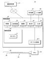
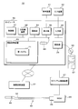
- FIG. 3 is an explanatory diagram illustrating the configuration of the catheter system 10.
- the catheter system 10 includes an information processing device 20, an MDU 33, and a diagnostic imaging catheter 40.
- the information processing device 20 includes a control unit 21, a main storage device 22, an auxiliary storage device 23, a communication unit 24, a display unit 25, an input unit 26, a catheter control unit 271, and a bus.
- the control unit 21 is an arithmetic control device that executes the program of the present embodiment.
- One or more CPUs Central Processing Units
- GPUs Graphics Processing Units
- TPUs Torsor Processing Units
- multi-core CPUs and the like are used for the control unit 21.
- the control unit 21 is connected to each hardware unit constituting the information processing device 20 via a bus.
- the main storage device 22 is a storage device such as SRAM (Static Random Access Memory), DRAM (Dynamic Random Access Memory), and flash memory.
- SRAM Static Random Access Memory
- DRAM Dynamic Random Access Memory
- flash memory temporary stores information necessary in the middle of processing performed by the control unit 21 and a program being executed by the control unit 21.
- the auxiliary storage device 23 is a storage device such as a SRAM, a flash memory, a hard disk, or a magnetic tape.
- the auxiliary storage device 23 stores a program to be executed by the control unit 21, a first model 71, and various data necessary for executing the program.
- the communication unit 24 is an interface for communicating between the information processing device 20 and the network.
- the display unit 25 is an interface that connects the display device 31 and the bus.
- the input unit 26 is an interface that connects the input device 32 and the bus.
- the catheter control unit 271 controls the MDU 33, controls the sensor 42, and generates a transverse layer image 485 and a longitudinal tomographic image based on the signal received from the sensor 42. Since the function and configuration of the catheter control unit 271 are the same as those of the conventionally used ultrasonic diagnostic apparatus, the description thereof will be omitted.
- the control unit 21 may realize the function of the catheter control unit 271.
- the information processing device 20 is an X-ray angiography device, an X-ray CT (Computed Tomography) device, an MRI (Magnetic Resonane Imaging) device, a PET (Positron Emission Tomography) device, or an ultrasound device via HIS (Hospital Information System) or the like. It is connected to various diagnostic imaging devices 37 such as an ultrasonic diagnostic device.
- the information processing device 20 of the present embodiment is a dedicated ultrasonic diagnostic device, a personal computer, a tablet, a smartphone, or the like having the function of the ultrasonic diagnostic device.
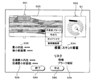
- FIG. 4 is an explanatory diagram illustrating an outline of processing by the catheter system 10.
- the control unit 21 acquires a set of transverse layer images 485 from the catheter control unit 271. Based on the acquired cross-layer image 485, the control unit 21 generates first information including determination information for determining a region to be treated and a region not to be treated.
- control unit 21 may make three or more stages of determination, such as "the area to be treated", “the boundary area between the treatment target and the non-treatment target”, and "the area outside the treatment target”.
- the control unit 21 may output the inner diameter of the luminal organ in each transverse layer image 485 together with the first information.
- control unit 21 determines the area to be treated and the area not to be treated along the longitudinal direction of the luminal organ.
- a stenosis to be treated is present in the central part of the region scanned by one image acquisition operation along the longitudinal direction of the luminal organ.
- the control unit 21 outputs the first support information that supports the diagnosis or treatment by the user based on the first information.
- a schematic diagram showing a treatment target for the tract organ or the periphery of the tract organ, a treatment method such as a recommended treatment and an instrument to be used, and a risk of complications associated with the treatment are first. Included in support information.
- the first support information also includes information on the treatment method such as the procedure for executing the recommended treatment and the equipment to be used.
- Information on the treatment method may be, for example, an instruction manual for the equipment.
- FIG. 5 is an explanatory diagram illustrating the configuration of the first model 71.
- the first model 71 is a model that accepts one set of transverse layer images 485 and outputs the necessity of treatment for the tract organ corresponding to each transverse layer image 485 or the periphery of the luminal organ.
- the "necessity of treatment” refers to whether or not IVR (Interventional Radiology), which treats the inside of the luminal organ, is necessary, and whether or not general treatment including medication and diet is necessary. good.
- the first model 71 may be a model that accepts the input of one transverse layer image 485 and outputs the necessity of treatment for the tract organ or the periphery of the luminal organ.
- the control unit 21 inputs the transverse layer image 485 to the first model 71 one by one, and performs a process of acquiring the necessity of treatment in the transverse layer image 485. Repeat for the number of sheets.
- the first model 71 is a model that accepts one set of cross-layer images 485 obtained by pullback operation by MDU33, one set of cross-layer images 485 obtained by manually moving the sensor 42 forward and backward. It may be a model that accepts input.
- the first model 71 accepts the input of a part of the transverse layer image 485, such as half or 1/3 of the transverse layer image 485 obtained by one pullback operation by the MDU33, and receives the input of the transverse organ or the cavity. It may be a model that outputs the necessity of treatment for the periphery of the organ.
- the control unit 21 repeats a process of inputting an acceptable number of cross-layer images 485 into the first model 71 and acquiring the necessity of treatment as many times as necessary. ..
- the first model 71 includes an input layer, a neural network 719, a plurality of softmax layers 711, a selection layer 712 connected to each softmax layer 711, and an output layer.
- the neural network 719 is, for example, a CNN (Convolutional Neural Network) having a pair of a plurality of convolutional layers and a pooling layer and a fully connected layer.
- the first model 71 has the same number of softmax layers 711 and selection layers 712 as the number of transverse layer images 485 that accept inputs. For each softmax layer 711, the neural network 719 outputs a feature amount indicating the probability of necessity of treatment for the luminal organ corresponding to one transverse layer image 485 or the periphery of the luminal organ.
- the feature amount is converted into a probability by the softmax layer 711. Specifically, for example, the probabilities for each layer such as "0% or more and less than 10%” and “10% or more and less than 20%" are output from the softmax layer 711.
- the selection layer 712 selects and outputs the probability of necessity of treatment for the luminal organ corresponding to one transverse layer image 485 or the periphery of the luminal organ.
- the cross-layer image 485 selects, for example, the layer having the highest probability and outputs a representative value thereof.
- the selection layer 712 may calculate and output the probability of necessity of treatment based on the representative value of each layer and the probability for the layer.
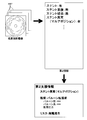
- FIG. 6 is an example of a screen displayed by the catheter system 10.
- a catheter system 10 used for treating stenosis of a blood vessel which is a kind of luminal organ, will be described as an example.
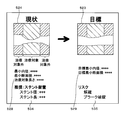
- the screen shown in FIG. 6 includes a schematic diagram column 524, a current dimension column 528, a target shape column 523, a target dimension column 529, a recommended treatment column 534, and a risk column 535.
- a schematic diagram obtained by extracting the inner diameter of the luminal organ based on the longitudinal tom image generated by the catheter control unit 271 is plotted in color based on the output of the first model 71. It is displayed.
- "not subject to treatment” indicates a portion output by the first model 71 that treatment is unnecessary.
- the minimum inner diameter of the luminal organ and the minimum cross-sectional area of the lumen of the luminal organ are displayed, which are calculated by image analysis of the longitudinal tom image acquired by the control unit 21 from the catheter control unit 271.
- the treatment target length calculated by integrating the slice thickness at the time of scanning with the number of cross-layer images 485 determined by the first model 71 to be the treatment target is displayed.
- the information displayed by the control unit 21 in the schematic diagram column 524 and the current dimension column 528 is an example of the first information.
- control unit 21 may display a vertical tomographic image in the schematic diagram column 524 instead of the schematic diagram.
- control unit 21 can display the portion to be treated by a display method such as enclosing it with a frame or coloring it. The user can confirm the state change along the longitudinal direction of the luminal organ by the schematic diagram column 524.
- the control unit 21 may display a three-dimensional schematic diagram in the schematic diagram column 524 and the target shape column 523. Specifically, the control unit 21 displays, for example, a cut model-like diagram cut by two planes intersecting at the central axis of the catheter. The user can easily grasp the morphology of the inner surface of the luminal organ from the three-dimensional schematic diagram.
- the target shape column 523 a schematic diagram deformed based on the treatment target is displayed.
- the target dimension column 529 the target minimum inner diameter and the target minimum cross-sectional area, which are the treatment targets, are displayed.
- the control unit 21 automatically acquires a treatment target based on a guideline or the like defined by a medical society or a medical facility.
- the control unit 21 determines the cross-sectional area of the lumen of the portion "not subject to treatment" and the target minimum opening rate. By integrating, the target minimum cross-sectional area after treatment is calculated. Further, the control unit 21 calculates the target minimum inner diameter by the equation (1).
- the above-mentioned calculation method of the target minimum inner diameter and the target minimum cross-sectional area is an example, and is not limited to this.
- the control unit 21 may display any item other than the target minimum inner diameter and the target minimum cross-sectional area in the target dimension column 529.
- the control unit 21 calculates the midpoint in the vertical direction in FIG. 6 of the lumen of the schematic diagram displayed in the schematic diagram column 524.
- the control unit 21 extracts points vertically separated from the calculated midpoint by half of the target minimum inner diameter calculated based on the equation (1). The extracted points indicate the surface of the target lumen after treatment.
- the control unit 21 extracts points indicating the surface of the target lumen after the treatment along the lateral direction in FIG.
- the control unit 21 generates a schematic diagram deformed based on the treatment target by using the line connecting the extracted points, and displays it in the target shape column 523.
- control unit 21 can generate a schematic diagram after treatment based on an arbitrary method.
- the recommended treatment column 534 the recommended treatment and the specifications of the instruments used for the treatment are displayed.
- the “stent placement” procedure is recommended and the appropriate stent specifications are displayed. Appropriate stent specifications will vary depending on the inner diameter of the stenosis and the length of the part requiring treatment.
- the treatment displayed by the control unit 21 in the recommended treatment column 534 is not limited to “stent placement”.
- the control unit 21 is based on, for example, “balloon angioplasty”, “thrombolysis”, “atelectomy”, “embolization”, “cauterization”, “drainage” based on the condition of the luminal organ and the luminal surroundings. , “Filter placement” and other recommended actions are displayed.
- control unit 21 may display treatment conditions such as pressure and time for pressurization in addition to the recommended balloon specifications.
- treatment conditions such as drug type, concentration, amount, and application time, in addition to the recommended catheter application specifications.
- the control unit 21 automatically selects the recommended treatment based on the guidelines set by the medical society or medical facility.
- the control unit 21 extracts recommended device specifications based on the selected treatment, minimum inner diameter, minimum cross-sectional area, and length of the treatment target area.
- control unit 21 may display the model number of the recommended device in the recommended treatment column 534.
- the control unit 21 may select and display a recommended device model number or the like from the inventory of devices held by the medical institution.
- the control unit 21 may display a plurality of recommended device model numbers. By displaying the model number, it is possible to quickly prepare the equipment to be used by the comedic staff such as nurses.
- the risk column 535 the risk for performing the treatment displayed in the recommended treatment column 534 is displayed.
- the control unit 21 automatically acquires the risk for the recommended treatment based on the guideline or the like established by the medical society or medical facility.
- control unit 21 displays the first support information by the target shape column 523, the recommended treatment column 534, and the risk column 535.
- the control unit 21 may display validity information indicating the validity of the information, such as the recommended level defined in the above-mentioned guideline and the like, and the name of the guideline which is the source.
- the control unit 21 may acquire the first support information by a learning model that accepts the input of the first information and outputs the first support information.
- the control unit 21 may acquire the first support information and its accuracy from the learning model and display it.
- the control unit 21 indicates that there is no part requiring treatment in the recommended treatment column 534. The user changes the length of inserting the diagnostic imaging catheter 40 into the luminal organ and performs the image acquisition operation again.
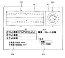
- FIG. 7 is an example of a screen displayed by the catheter system 10.
- the stent indwelled in the target shape column 523 is schematically shown. The user can confirm that stent placement is recommended in the target shape column 523 in addition to the recommended treatment column 534.
- the control unit 21 may accept changes in the treatment displayed in the recommended treatment column 534. For example, the user can be instructed to change "stent placement" to "balloon angioplasty” via a user interface such as a pull-down menu or voice input.
- the control unit 21 outputs the specifications of the balloon used when performing the treatment of balloon angioplasty, the expansion pressure, and the like to the recommended treatment column 534.
- the specifications of the balloon output by the control unit 21 are, for example, the balloon type name, dimensions, and balloon type.
- the dimensions of the balloon include the total length of the balloon and the outer diameter when expanded.
- the types of balloons are, for example, semi-compliant balloons and non-compliant balloons.
- the control unit 21 may output a compliance chart showing the relationship between the pressure applied to the balloon and the outer diameter.
- FIG. 8 is a flowchart illustrating the flow of program processing.
- the control unit 21 acquires a set of transverse layer images 485 from the catheter control unit 271 (step S801).
- the control unit 21 inputs the acquired transverse layer image 485 into the first model 71, and inputs the first information regarding the necessity of treatment for the tract organ corresponding to each transverse layer image 485 or the periphery of the luminal organ. Acquire (step S802).
- the control unit 21 determines the necessity of treatment (step S803). Specifically, the control unit 21 determines whether or not there is a cross-layer image 485 for which the determination that treatment is required is output from the first model 71.
- control unit 21 displays in the recommended treatment column 534 that no treatment is required (step S804). After that, the control unit 21 ends the process.
- control unit 21 analyzes the transverse layer image 485 or the longitudinal tomographic image acquired from the catheter control unit 271 to obtain the inner diameter of the portion that is “not treated” and the inner diameter of the portion.
- the cross-sectional area, the inner diameter of the constricted portion, and the cross-sectional area are calculated (step S811).
- control unit 21 performs processing such as edge extraction to extract the inner boundary of the luminal organ.
- the control unit 21 extracts the inner diameter of the luminal organ and the cross-sectional area of the lumen from each transverse layer image 485.
- the control unit 21 calculates representative values of the inner diameter and the cross-sectional area in the cross section determined by the first model 71 to be out of the treatment target.
- the control unit 21 calculates the minimum inner diameter and the minimum cross-sectional area in the cross section determined by the first model 71 to require treatment, that is, the inner diameter and the cross-sectional area of the constricted portion.
- the control unit 21 calculates the length of the treatment target by integrating the slice thickness at the time of scanning with the number of cross-layer images 485 determined by the first model 71 as the treatment target (step S812).
- the control unit 21 may calculate the length to be treated based on the length of the portion whose inner diameter or cross-sectional area is less than a predetermined reference.
- the control unit 21 automatically acquires a recommended treatment method based on a guideline or the like defined by a medical society or a medical facility (step S813).
- the guidelines and the like are arranged in the form of a flowchart or a selection tree, for example, and are stored in the auxiliary storage device 23.
- the control unit 21 acquires necessary information from an electronic medical record or the like, or displays a dialog box requesting input by the user.
- the control unit 21 automatically acquires a treatment target based on the above-mentioned guidelines and the like (step S814). For example, when the target minimum opening rate after treatment is set based on the area in a guideline or the like, the control unit 21 calculates a representative value regarding the cross-sectional area of the lumen of the portion that is “not subject to treatment”.
- the representative value is an arbitrary statistic such as an average value, a minimum value, or a maximum value.
- the representative value may be, for example, the cross-sectional area of the central portion of the portion "not treated" along the longitudinal direction of the luminal organ.
- the control unit 21 calculates the target minimum cross-sectional area after treatment by integrating the calculated representative value and the target minimum opening rate. Further, the control unit 21 calculates the target minimum inner diameter by the above equation (1) based on the target minimum cross-sectional area.
- the above-mentioned calculation method of the target minimum inner diameter and the target minimum cross-sectional area is an example, and is not limited to this.
- the control unit 21 may display any item other than the target minimum inner diameter and the target minimum cross-sectional area in the target dimension column 529.
- the control unit 21 may accept the input of the treatment target by the user.
- the user inputs the treatment goal, for example, numerically.
- the user may input the treatment target on the schematic diagram column 524 by tapping or the like.
- the control unit 21 acquires the recommended treatment device (step S815). Specifically, the type of treatment device is determined by the treatment method acquired in step S813. For example, when performing "stent placement", a stent is used.
- the control unit 21 determines the diameter and length of the stent based on the inner diameter and cross-sectional area of the “non-treatment target” portion and the stenosis portion calculated in step S811 and the treatment target length calculated in step S812. ..
- the treatment device recommended by the control unit 21 is not limited to the stent.
- the therapeutic device may be any intraluminal device, such as an intraluminal indwelling filter or embolic coil. If the luminal organ of interest is a blood vessel, the intraluminal indwelling device may be an intravascular indwelling device.
- the treatment device may be a lumen inner diameter expansion device such as an expansion balloon or a rotablator, an energy treatment device such as a laser treatment catheter, or a drug application device such as a drug application catheter.
- the control unit 21 automatically acquires the risk associated with the treatment based on the above-mentioned guidelines and the like (step S816).
- the control unit 21 generates a schematic diagram to be displayed in the schematic diagram column 524 and the target shape column 523 (step S817).
- the control unit 21 calculates the midpoint in the vertical direction in FIG. 6 of the lumen of the schematic diagram displayed in the schematic diagram column 524.
- the control unit 21 extracts points vertically separated from the calculated midpoint by half of the target minimum inner diameter calculated based on the equation (1). The extracted points indicate the surface of the target lumen after treatment.
- the control unit 21 extracts points indicating the surface of the target lumen after the treatment along the lateral direction in FIG.
- the control unit 21 generates a schematic diagram deformed based on the treatment target by using the line connecting the extracted points, and displays it in the target shape column 523.
- control unit 21 can generate a schematic diagram after treatment based on an arbitrary method.
- the control unit 21 displays the screen described with reference to FIG. 6 or 7 (step S818). After that, the control unit 21 ends the process.
- a catheter system 10 that automatically determines and outputs a range requiring treatment along the longitudinal direction of a luminal organ. Therefore, it is possible to provide a catheter system 10 that can be easily used even by a relatively inexperienced user.
- a catheter system 10 that displays the content of a recommended treatment and the specifications of the recommended equipment used for the treatment when treatment is required. The user can quickly determine the necessary equipment even for equipment having various specifications such as a stent.
- control unit 21 may select and display the model number of the recommended equipment from the list of equipment owned by the medical institution. It is possible to provide a catheter system 10 that allows a user to quickly determine equipment.
- the control unit 21 may display a plurality of specifications or model numbers of recommended equipment. The user can select the equipment to be used from a professional point of view.
- a catheter system 10 that displays the risk of treatment.
- the user can take careful action to avoid the risk. Comedic staff, etc. can prepare for unforeseen circumstances by checking the risk display.
- the control unit 21 may accept the selection of a treatment different from the recommended treatment and display the equipment recommended for the treatment and the risk of the treatment. It is possible to provide a catheter system 10 that assists the user even when the user selects a procedure different from the procedure recommended by the control unit 21.
- the present embodiment relates to a catheter system 10 in which a user manually inputs a lesion site.
- the description of the parts common to the first embodiment will be omitted.
- FIG. 9 is an example of a screen displayed by the catheter system of the second embodiment.
- a vertical tomographic image column 52 On the screen shown in FIG. 9, a vertical tomographic image column 52, a cross-layer image column 51, an item selection column 585, a start button 588, and an end button 589 are displayed.
- the above-mentioned cross-layer image 485 is displayed in the cross-layer image column 51.
- a vertical tomographic image generated by the catheter control unit 271 is displayed.
- a cross-layer position marker 551 indicating the position of the cross-layer image 485 displayed in the cross-layer image column 51 is displayed at the edge of the vertical tomographic image column 52.
- a vertical fault position marker 552 indicating the position of the vertical tomographic image displayed in the vertical tomographic image column 52 is displayed at the edge of the cross-layer image column 51.
- the control unit 21 displays, for example, the cross-layer image 485 having the highest degree of stenosis, which will be described later, in the cross-layer image column 51 by default.
- the user can appropriately change the cross section to be displayed by operating the input device 32 to change the positions of the transverse layer position marker 551 and the longitudinal fault position marker 552.
- the control unit 21 may accept voice input from the user.
- the control unit 21 may display a marker indicating the position of the characteristic cross-layer image 485 including the cross-layer image 485 having the highest degree of stenosis on the edge of the vertical tomographic image column 52.
- the control unit 21 displays the cross-layer image 485 corresponding to the selected marker.
- FIG. 9 shows an example in which the “lesion area” is being input.
- the user can adjust the closed curve 576 so as to surround the "lesion area" by appropriately operating the cursor 575.
- the control unit 21 sets the closed curve 576 that is not operated by the cursor 575 so that the height of the closed curve 576 superimposed on the vertical tomographic image column 52 and the height of the closed curve 576 superimposed on the cross-layer image column 51 match. Adjust automatically.
- the user selects the end button 589 after enclosing the desired range with the closed curve 576 by also using the operation of the cross layer position marker 551 and the longitudinal fault position marker 552.
- the control unit 21 accepts the end of setting the "lesion area”.
- the "lesion area” is an example of the first information regarding the state of the tract organ or the state around the tract organ. That is, the control unit 21 acquires the first information input by the user based on the tomographic image generated by using the diagnostic imaging catheter 40 inserted into the luminal organ.
- control unit 21 may accept inputs such as "calcification region” and "plaque region”.
- the control unit 21 is responsible for accepting the designation of the width or length of a specific part instead of the area. All of these are examples of the first region.
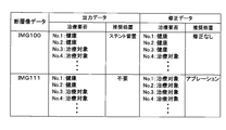
- a post-treatment tomographic image 487 obtained by using a diagnostic imaging catheter 40 after performing an intraluminal treatment, specifically, a tomographic image 487 (see FIG. 22).
- a post-treatment longitudinal tomographic image and a post-treatment transverse layer image may be displayed, respectively.
- the control unit 21 receives information on the state after the treatment based on the post-treatment tomographic image 487.
- FIG. 10 is a flowchart illustrating a processing flow of the program of the second embodiment.
- the control unit 21 acquires a set of transverse layer image 485 and a longitudinal tomographic image from the catheter control unit 271 (step S831).
- the control unit 21 displays the acquired cross-layer image 485 and the vertical tomographic image on the screen described with reference to FIG. 9 (step S832).
- the control unit 21 acquires the first information such as the range of the lesion area based on the operation of the item selection field 585, the start button 588, the cursor 575, the end button 589, etc. by the user (step S833).
- the control unit 21 calculates dimensions such as the area, volume, and length of the lesion area based on the acquired first information (step S834).
- the control unit 21 determines the necessity of treatment based on a guideline or the like defined by a medical society or a medical facility (step S835).
- the guidelines and the like are arranged in the form of a flowchart or a selection tree, for example, and are stored in the auxiliary storage device 23.
- control unit 21 acquires necessary information from an electronic medical record or the like, or displays a dialog box requesting input by the user.
- control unit 21 displays in the recommended treatment column 534 that no treatment is required (step S804). After that, the control unit 21 ends the process.
- control unit 21 automatically acquires the recommended treatment method based on the above-mentioned guidelines and the like (step S813). Since the subsequent processing is the same as the processing flow described with reference to FIG. 8, the description thereof will be omitted.
- a catheter system 10 in which a user can manually input a first region.
- a catheter system 10 that can be used even when a highly accurate first model 71 has not been generated.
- the present embodiment relates to a catheter system 10 in which the catheter control device 27 and the information processing device 20 are separate bodies. The description of the parts common to the first embodiment will be omitted.
- FIG. 11 is an explanatory diagram illustrating the configuration of the catheter system 10 of the third embodiment.
- the catheter system 10 of the present embodiment includes an information processing device 20, a catheter control device 27, an MDU 33, and a diagnostic imaging catheter 40.
- the information processing device 20 includes a control unit 21, a main storage device 22, an auxiliary storage device 23, a communication unit 24, a display unit 25, an input unit 26, and a bus.
- the catheter control device 27 is an ultrasonic diagnostic device for IVUS that controls the MDU 33, controls the sensor 42, and generates a transverse layer image 485 and a longitudinal tomographic image based on the signal received from the sensor 42. Since the function and configuration of the catheter control device 27 are the same as those of the conventionally used ultrasonic diagnostic device, the description thereof will be omitted.
- the catheter control device 27 and the information processing device 20 may be directly connected via a cable or wireless communication, or may be connected via a network.
- the information processing device 20 of the present embodiment is a general-purpose personal computer, tablet, smartphone, large computer, virtual machine operating on the large computer, cloud computing system, or quantum computer.
- the information processing device 20 may be a plurality of personal computers or the like that perform distributed processing.
- the present embodiment relates to a catheter system 10 that maps a plurality of types of objects included in a tomographic image acquired by a diagnostic imaging catheter 40 in association with the arrangement of each object.
- FIG. 12 is an explanatory diagram illustrating an outline of processing by the catheter system 10 of the fourth embodiment.
- the control unit 21 acquires a set of transverse layer images 485 from the catheter control unit 271.
- the control unit 21 generates a horizontal object arrangement image 483 based on the acquired transverse layer image 485.
- the horizontal object arrangement image 483 is an image in which a plurality of object types included in the cross-sectional layer image 485 are mapped in association with each object's range.
- the control unit 21 generates a vertical object arrangement image 484 based on a set of horizontal object arrangement images 483. Specifically, the control unit 21 extracts the pixels at the positions corresponding to the vertical tomographic images from each of the horizontal object arrangement images 483, performs interpolation processing, and reconstructs the vertical objects corresponding to the vertical tomographic images.
- the arrangement image 484 is formed. Since this process is the same as the method of forming a vertical tomographic image from one set of transverse layer images 485, the details thereof will be omitted.
- Three-dimensional semantic segmentation may be performed in which three-dimensional data is generated based on one set of cross-layer images 485 and labels indicating the types of objects are given to each voxel. From the 3D object arrangement image generated by the 3D semantic segmentation result, the vertical object arrangement image 484 corresponding to the vertical tom image can be generated.
- the horizontal object arrangement image 483 and the vertical object arrangement image 484 are examples of the first information regarding the state of the tract organ or the state around the tract organ.
- the first information may include the length, area, angle, volume, etc. of the objects calculated based on the horizontal object arrangement image 483 and the vertical object arrangement image 484.
- the first information may include the length, area, angle, volume, etc. of the tract organ or the periphery of the tract organ calculated based on the tomographic image taken by the diagnostic imaging catheter 40.
- the first information may include information on blood flow.
- the control unit 21 outputs the first support information that supports the diagnosis or treatment by the user based on the first information.
- the first support information includes a schematic diagram showing a treatment target for the tract organ or the periphery of the tract organ, a treatment method such as a recommended treatment and an instrument to be used, and a risk associated with the treatment. ing.
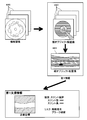
- FIG. 13 is an explanatory diagram illustrating the first model 71.
- the first model 71 is a model that accepts the cross-layer image 485 and outputs a horizontal object arrangement image 483 that maps the types of a plurality of objects included in the cross-layer image 485 in association with the range of each object. ..
- the first model 71 is generated by machine learning.
- the vertical line hatching is the "cross section of the diagnostic imaging catheter 40"
- the horizontal line hatching is the "luminal organ wall”
- the lower right hatching is the "luminal organ”.
- downward-sloping hatches indicate “guide wires”
- thin grid-like hatches indicate "calcification”.
- the "guide wire” includes the guide wire itself, multiple echoes generated by the guide wire, and acoustic shadows generated by the guide wire.
- “calcification” includes the calcified part itself, multiple echoes caused by the calcified part, and acoustic shadows caused by the calcified part.
- FIGS. 12 and 13 schematically shows that each object is painted in a different color.
- Coloring objects is an example of how to display each object separately. It may be displayed so as to be distinguishable from other objects by any aspect such as surrounding the outer edge of each object.
- cross section of diagnostic imaging catheter is examples of objects included in the transverse layer image 485.
- the "guide wire itself”, the “multiple echoes generated by the guide wire”, and the “acoustic shadow generated by the guide wire” may be classified into different objects.
- lesions such as “plaque” and “dissociation” formed on the wall of a luminal organ may be classified into different objects.
- the first model 71 is a model that accepts one set of transverse layer image 485 obtained by pullback operation by MDU33, but accepts input of one set of transverse layer image 485 obtained by manually moving the sensor 42 forward and backward. It may be.
- the first model 71 may be a model that accepts the input of one transverse layer image 485.
- the first model 71 may be a model that accepts inputs such as half or 1/3 of the cross-layer image 485 obtained by one pullback operation.
- the first model 71 is, for example, a semantic segmentation model, and includes an input layer, a neural network, and an output layer.
- the neural network has a U-Net structure that realizes, for example, semantic segmentation.
- the U-Net structure is composed of a multi-layered encoder layer and a multi-layered decoder layer connected behind the multi-layered encoder layer. Semantic segmentation assigns a label to each pixel that makes up the input image, indicating the type of object.
- the control unit 21 determines the display method of each pixel according to the label, and as shown in the horizontal object arrangement image 483 of FIG. 13, the output image in which the objects are mapped according to different colors or ground patterns for each type. Can be generated.
- the first model 71 may be a model that realizes image segmentation generated based on a Mask R-CNN model or any other machine learning algorithm.
- the information of the adjacent cross-layer images 485 is reflected in the horizontal object arrangement image 483. Therefore, it is possible to realize the first model 71 that is less susceptible to noise and the like in each cross-sectional layer image 485 and accurately outputs the range of the object.
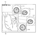
- FIG. 14 is an example of a screen displayed by the catheter system of the fourth embodiment.
- the screen shown in FIG. 14 includes a vertical object arrangement column 525, a cross-layer image column 51, a current dimension column 528, a target dimension column 529, a recommended action column 534, and a risk column 535.
- the above-mentioned vertical object arrangement image 484 is displayed in the vertical object arrangement column 525.
- the above-mentioned cross-layer image 485 is displayed in the cross-layer image column 51.
- the minimum inner diameter of the luminal organ and the minimum cross-sectional area of the lumen of the luminal organ calculated by image analysis of the vertical object arrangement image 484 or the vertical tomographic image acquired from the catheter control unit 271 in the current dimension column 528. Is displayed.
- the control unit 21 displays the first information regarding the state of the blood vessel which is a luminal organ or the state around the blood vessel by the vertical object arrangement column 525 and the current dimension column 528.
- the target dimension column 529 the target minimum inner diameter and the target minimum cross-sectional area, which are the treatment targets, are displayed.
- the recommended action is displayed in the recommended action column 534.
- the control unit 21 may further display the specifications of the instrument used for the treatment in the recommended treatment column 534.
- the risk column 535 the risk for performing the treatment indicated in the recommended treatment column 534 is displayed.
- the control unit 21 displays the first support information by the target dimension column 529, the recommended action column 534, and the risk column 535.
- the control unit 21 may display the risk of not performing the treatment indicated in the recommended treatment column 534 in the risk column 535.
- the control unit 21 may display the vertical tom image acquired from the catheter control unit 271 in the vertical object arrangement column 525 instead of the vertical object arrangement image 484 based on the user's instruction.
- the control unit 21 may display the horizontal object arrangement image 483 in the cross-sectional layer image column 51 instead of the cross-sectional layer image 485 based on the user's instruction.
- the control unit 21 may display a function evaluation result such as a coronary blood flow reserve ratio (FFR: Fractional Flow Reserve) instead of the current dimension column 528 or together with the current dimension column 528.
- FFR coronary blood flow reserve ratio
- the control unit 21 can measure the coronary blood flow reserve ratio by using a pressure wire inserted into the coronary artery instead of the diagnostic imaging catheter 40.
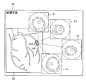
- FIG. 15 is an example of a screen displayed by the catheter system 10 of the fourth embodiment.
- the control unit 21 displays the screen shown in FIG. ..
- the user can input an instruction to display the rationale by, for example, double-clicking the character string of "plaque failure" in the risk column 535.
- the control unit 21 may accept voice input from the user.
- a reason column 516 indicating that it is determined that "vulnerable plaque” is present in this portion is displayed.
- the control unit 21 extracts, for example, the cross-layer image 485 having the largest area of the object corresponding to the “vulnerable plaque” and displays it in the cross-layer image column 51.
- the control unit 21 moves the cross-layer position marker 551 to a position indicating the position of the tomographic image displayed in the cross-layer image column 51.
- markers indicating the range of "vulnerable plaque” and the like are not displayed.
- the user can directly observe the cross-layer image 485.
- the user operates the cross-layer position marker 551 as necessary to observe the cross-layer images 485 before and after the cross-layer image 485 displayed by the control unit 21, and takes any action based on a professional viewpoint. Can be judged.
- FIG. 16 is an example of a screen displayed by the catheter system of the fourth embodiment.
- the control unit 21 displays the screen shown in FIG.
- a cross-layer image 485 overlaid with a ground marker 561 indicating a ground region on which the determination of “vulnerable plaque” is based is displayed.
- the control unit 21 extracts the basis area by, for example, a model visualization method such as Grad-CAM (Gradient-weighted Class Activation Mapping) or Grad-CAM ++.
- the rationale region is a region in the plurality of transverse layer images 485 input to the first model 71 that strongly affects the output of the pixels determined to be “calcified”.
- the rationale marker 561 is displayed using finer hatching in places where the degree of influence on the output is higher.
- the cross-layer image 485 containing the “vulnerable plaque” described with reference to FIG. 16 and the rationale marker 561 described with reference to FIG. 16 are examples of rationale information regarding the risk of “plaque rupture”.
- control unit 21 displays the rationale marker 561 on the screen described with reference to FIG. 16 while the user operates the cursor and presses and holds the reason column 516.
- the control unit 21 erases the basis marker 561 and returns to the screen described with reference to FIG.
- the control unit 21 may switch whether or not the basis marker 561 is displayed each time the user clicks the reason column 516.
- the control unit 21 may switch the display / non-display of the basis marker 561.
- the control unit 21 may display the rationale marker 561 by default and delete the rationale marker 561 while the user presses and holds the rationale marker 561.
- the control unit 21 may switch between the screen described with reference to FIG. 15 and the screen described with reference to FIG. 16 based on the voice input.
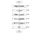
- FIG. 17 is a flowchart illustrating a processing flow of the program of the fourth embodiment.
- the control unit 21 acquires a set of transverse layer images 485 from the catheter control unit 271 (step S851).
- the control unit 21 inputs the acquired cross-layer image 485 into the first model 71, and the horizontal object arrangement image 483 that associates the types of a plurality of objects included in the cross-layer image 485 with the range of each object. Then, the probability that the determination of the object for each pixel is correct is acquired (step S852).
- the control unit 21 generates a vertical object arrangement image 484 based on one set of horizontal object arrangement images 483 (step S853).
- the control unit 21 records the generated horizontal object arrangement image 483 and vertical object arrangement image 484 in the auxiliary storage device 23.
- the control unit 21 analyzes the horizontal object arrangement image 483 and the vertical object arrangement image 484 to calculate the dimensions of the portion not to be treated and the maximum stenosis portion (step S854).
- the maximum stenotic part means a part where the degree of stenosis is the most remarkable.
- the control unit 21 extracts the cross-sectional area of the lumen from each horizontal object arrangement image 483.
- the cross-sectional area of the lumen can be calculated by integrating the number of pixels constituting the object indicating the lumen and the area per pixel.
- the control unit 21 determines that the maximum value of the calculated cross-sectional area is the cross-sectional area of the portion not to be treated, and determines that the minimum value is the cross-sectional area of the maximum constricted portion.
- the criteria for determining the part not to be treated and the maximum stenosis are not limited to the area. For example, it may be determined based on any dimension such as the maximum inner diameter or the average diameter.
- the control unit 21 may accept the designation of the portion not to be treated and the maximum stenosis portion by the user.
- the control unit 21 determines the degree of stenosis of the luminal organ (step S855).
- the degree of stenosis is defined by, for example, Eq. (1) or Eq. (2).
- the formula for calculating the degree of stenosis is not limited to the formulas (1) and (2).
- the control unit 21 may accept the selection or input of the stenosis degree calculation method from the user.
- the control unit 21 determines the necessity of treatment based on a guideline or the like defined by a medical society or a medical facility (step S856).
- the guidelines and the like are arranged in the form of a flowchart or a selection tree, for example, and are stored in the auxiliary storage device 23.
- control unit 21 acquires necessary information from an electronic medical record or the like, or displays a dialog box requesting input by the user.
- control unit 21 displays in the recommended treatment column 534 that no treatment is required (step S804). After that, the control unit 21 ends the process.
- the control unit 21 calculates the length of the stenotic portion to be treated based on the above-mentioned guidelines and the like (step S857). For example, the control unit 21 calculates the length in a range in which the cross-sectional area of the lumen is smaller than the threshold value defined by the guideline or the like. The control unit 21 automatically acquires the recommended treatment method based on the above-mentioned guidelines and the like (step S813).
- step S816 Since the processing up to step S816 is the same as the processing flow described with reference to FIG. 8, the description thereof will be omitted.
- the control unit 21 displays the screen described with reference to FIGS. 15 and 16 (step S861). After that, the control unit 21 ends the process.
- a catheter system 10 that appropriately switches and displays a vertical object arrangement image 484 and a vertical tomographic image. The user can switch and observe the displayed image as needed.
- a catheter system 10 that displays the necessity of treatment, recommended treatment, and risk.
- a cross-layer image 485 of a site determined to be at risk and a catheter system 10 that automatically displays the basis for determining the risk.
- the present embodiment relates to a catheter system 10 that receives a tomographic image acquired by a diagnostic imaging catheter 40 and outputs findings relating to a tract organ or a state around the tract organ.
- the description of the parts common to the first embodiment will be omitted.
- FIG. 18 is an explanatory diagram illustrating an outline of processing by the catheter system of the fifth embodiment.
- the control unit 21 acquires a set of transverse layer images 485 from the catheter control unit 271. Based on the acquired cross-layer image 485, the control unit 21 acquires findings regarding the tract organ or the state around the luminal organ, such as the necessity of treatment and the presence or absence of blood flow stasis.
- the finding acquired by the control unit 21 is the probability regarding a predetermined option such as "yes” or "no" for each of the plurality of items. Details of the findings will be described later.
- the findings are an example of the first information regarding the condition of the tract organ or the condition around the tract organ.
- the control unit 21 outputs the first support information that supports the diagnosis or treatment by the user based on the first information.
- the state of the indwelling device indwelled in or around the tract organ, the treatment method such as the recommended treatment and the instrument to be used, and the risk associated with the treatment are included in the first support information. ing.
- FIG. 19 is an explanatory diagram illustrating the configuration of the first model 71 of the fifth embodiment.
- the first model 71 of the present embodiment accepts one set of transverse layer images 485 and states the condition of the luminal organ, such as the necessity of treatment, the presence or absence of blood flow stasis, or the presence or absence of bifurcation, or the tube. It is a model that outputs findings related to the condition around the cavity organ.
- the "necessity of treatment” refers to whether or not IVR (Interventional Radiology), which treats the inside of the luminal organ, is necessary, and whether or not general treatment including medication and diet is necessary. good.
- the finding output by the first model 71 is the probability regarding a predetermined option such as "yes" or "no" for each of the plurality of items.
- Tables 1 to 4 show examples of items for which the first model 71 outputs a probability. One row in Tables 1 to 4 indicates one item. The first model 71 outputs the probability of choice for each item.
- Tables 1 to 4 show examples of items included in the findings output by the first model 71.
- Table 1 shows items related to blood flow information.
- Table 2 shows items related to blood flow information.
- Table 3 shows items related to qualitative shape information of the tract organ and the circumference of the tract organ.
- Table 4 shows items related to property information indicating the properties of the tract organ and the surroundings of the tract organ.
- “Intrastent stenosis” shown in Table 4 indicates the presence or absence of stenosis of a stent placed in a luminal organ several months to several years ago, for example.
- a transverse layer image 485 is taken immediately after the stent placement procedure, it indicates the presence or absence of stenosis of the placed stent. That is, the cross-layer image 485 is taken immediately after the completion of a series of intraluminal treatments, whether it is a tomographic image of an untreated luminal organ or a tomographic image of a luminal organ under follow-up after treatment. It may be a tomographic image of a luminal organ.
- Table 5 shows items related to device information indicating the state of indwelling devices such as stents placed in the luminal organ.
- the first model 71 may output the probabilities for some of the items shown in Tables 1 to 5.
- the first model 71 may output the probabilities for items other than the items shown in Tables 1 to 5.
- the first model 71 may be a model that accepts the input of one transverse layer image 485 and outputs the findings regarding the state of the tract organ or the state around the tract organ.
- the first model 71 includes an input layer, a neural network 719, a plurality of softmax layers 711, and an output layer.
- the neural network 719 is, for example, a CNN (Convolutional Neural Network) having a pair of a plurality of convolutional layers and a pooling layer and a fully connected layer.
- One softmax layer 711 is provided for one row shown in Tables 1 to 4.
- An image in which one set of transverse layer images 485 are combined in the scanning order to form one image is input to the input layer.
- the probabilities for each item shown in Tables 1 to 4 are output to the output layer via the neural network 719 and the softmax layer 711.
- the probability of "absence” for "necessity of treatment” is 95%
- the probability of "absence” for "blood flow stasis” is 90%
- the probability of "branching” is "yes”.
- the first model 71 may be separated from Table 1 to Table 3.
- the first model 71 may be separated for each output item.
- a selection layer that selects and outputs the option with the highest probability may be provided after the softmax layer 711.
- Data in the stage before forming the transverse layer image 485, such as sound line data acquired by the catheter control unit 271 from the sensor 42, may be input to the first model 71.
- FIG. 20 is an example of a screen displayed by the catheter system 10 of the fifth embodiment.
- the screen shown in FIG. 20 includes a vertical tomographic image column 52, a cross-layer image column 51, a finding column 53, a current dimension column 528, a target dimension column 529, a recommended treatment column 534, and a risk column 535.
- a vertical tomographic image acquired from the catheter control unit 271 is displayed.
- a cross-layer image 485 acquired from the catheter control unit 271 is displayed. That is, in FIG. 20, a post-treatment longitudinal tomographic image and a post-treatment cross-layer image after the treatment on the luminal organ are displayed.
- the indwelling stent is depicted in the longitudinal tomographic image and the transverse layer image 485 in FIG. 20. Stents are indicated by multiple black circles.
- the control unit 21 selects a finding having a higher probability than a predetermined threshold value from the findings acquired from the first model 71 and displays it in the finding column 53.
- the findings displayed by the control unit 21 in the finding column 53 are examples of the first information regarding the state of the tract organ or the state around the tract organ.
- the current dimension column 528, the target dimension column 529, the recommended treatment column 534, and the risk column 535 are the same as the screen of the fourth embodiment described with reference to FIG. 14, so the description thereof will be omitted.
- the information displayed by the control unit 21 in the recommended treatment column 534, the target dimension column 529, and the risk column 535 is an example of the first support information that supports the diagnosis or treatment.
- the finding is "stent abnormality (malaposition)", that is, the indwelling stent is not in proper contact with the inner wall of the luminal organ. "Balloon dilation” is recommended to re-expand the stent from the inside.
- the user can operate the transverse layer position marker 551 and the longitudinal tomographic position marker 552 to check the condition of the stent and the condition of the luminal organ and determine the actual treatment to be performed.
- FIG. 21 is an example of a screen displayed by the catheter system 10 of the fifth embodiment.
- the control unit 21 displays the screen shown in FIG.
- the vertical tomographic image column 52 a vertical tomographic image on which a ground marker 561 indicating a ground region on which the determination of "dissociation" is based is superimposed is displayed.
- the control unit 21 is defined by a medical society or a medical facility when, for example, the luminal organ wall at the end of the indwelling stent is thin, or when vulnerable plaque is present near the end of the stent. Display the risk of "dissociation" based on guidelines. The control unit 21 superimposes and displays the evidence marker 561 on the area corresponding to the reason for these risks.
- the rationale marker 561 described with reference to FIG. 21 is an example of rationale information regarding the first support information indicating the risk of “dissociation”.
- control unit 21 extracts the basis region by a model visualization method such as Grad-CAM or Grad-CAM ++ and displays the basis marker 561. May be good.
- step S802 the control unit 21 inputs a transverse layer image 485 into the first model 71 described with reference to FIG. 19 to obtain findings regarding the luminal organ or the condition around the luminal organ.
- step S812 the control unit 21 calculates the length of the stenotic portion to be treated based on the guideline or the like.
- control unit 21 may display the evidence marker 561 indicating the basis of the findings displayed in the finding column 53.
- the control unit 21 can extract the basis area related to the findings output from the first model 71 by a model visualization method such as Grad-CAM or Grad-CAM ++.
- medical information acquired in real time such as an image taken by the diagnostic imaging apparatus 37, blood pressure, heart rate, oxygen saturation, etc. may be input to the first model 71.
- medical information acquired from an electronic medical record such as a pre-existing condition, height, weight, and images taken by a diagnostic imaging apparatus 37 in the past, may be input to the first model 71.
- the first model 71 accepts the cross-layer image 485 and medical information, and states the condition of the luminal organ, such as the necessity of treatment, the presence or absence of blood flow stasis, or the presence or absence of bifurcation, or Output findings regarding the condition around the luminal organ.
- medical information other than the cross-layer image 485 in the input data of the first model 71 it is possible to provide the catheter system 10 that outputs highly accurate findings.
- Embodiment 6 relates to a catheter system 10 that uses a set of post-treatment tomographic images 487 taken with a diagnostic imaging catheter 40 after, for example, performing a procedure such as stent placement. Treatment is not limited to placing the device in a luminal organ. For example, if the luminal organ is a blood vessel, it may be a procedure without a device such as "balloon angioplasty", “thrombolysis” or "atherectomy". The description of the parts common to the fifth embodiment will be omitted.
- FIG. 22 is an explanatory diagram illustrating an outline of processing by the catheter system of the sixth embodiment.
- the control unit 21 acquires a set of post-treatment tomographic images 487 taken by using the diagnostic imaging catheter 40 after performing treatment such as stent placement.
- the second model is used instead of the first model 71 of the fifth embodiment.
- the second model outputs the second information regarding the post-treatment tract organ or the state of the luminal organ.
- the second model has the same configuration as the first model 71 described with reference to FIG. 19, and outputs items related to the state after the treatment.
- Each item shown in Table 4 above is an example of the items output by the second model.
- the items output by the second model are not limited to the qualitative items related to the state of the indwelling device such as the stent shown in Table 4.
- the second model may output qualitative items such as, for example, the average inner diameter of the stent, the dimensional change of the inner diameter of the stent along the longitudinal direction of the luminal organ, or the length of the stent after placement.
- the second model may output items related to the condition after performing any treatment, such as the condition of the luminal organ after dilation.
- a second model that outputs arbitrary items can be used.
- the user inserts the image diagnostic catheter 40 of the luminal organ after the treatment and performs an image acquisition operation.
- the control unit 21 acquires a set of post-treatment tomographic images 487 from the catheter control unit 271.
- the control unit 21 inputs the acquired post-treatment tomographic image 487 into the second model to acquire the second information regarding the tract organ and the state around the tract organ.
- the control unit 21 selects a finding having a higher probability than a predetermined threshold value among the findings acquired from the second model.
- the control unit 21 determines whether or not additional measures such as re-expansion of the stent are necessary based on the above-mentioned guidelines and the like.
- the control unit 21 determines the second support information such as the target size of the additional treatment, the recommended treatment, and the risk based on the above-mentioned guideline.
- the control unit 21 displays the post-treatment tomographic image 487 and the determination result on the display device 31.
- the screen displayed by the control unit 21 is the same as the screen of the fifth embodiment described with reference to FIGS. 20 and 21.
- the findings displayed by the control unit 21 in the findings column 53 are examples of the second information regarding the state of treatment.
- the information displayed by the control unit 21 in the recommended treatment column 534, the target dimension column 529, and the risk column 535 is an example of the second support information that supports the diagnosis or treatment.
- the second model which has been specially trained on the items related to the tract organ after the treatment and the condition around the tract organ, the accuracy with respect to the condition after the treatment is high.
- a catheter system 10 that outputs information can be provided.
- medical information acquired in real time such as an image taken by the diagnostic imaging apparatus 37, blood pressure, heart rate, oxygen saturation, etc. may be input to the second model.
- medical information acquired from an electronic medical record such as a pre-existing condition, height, weight, and images taken in the past using the diagnostic imaging apparatus 37, may be input to the second model.
- the second model accepts the post-treatment tomographic image 487 and medical information, and outputs the second information regarding the treatment status.
- medical information other than the post-treatment tomographic image 487 in the input data of the second model, it is possible to provide the catheter system 10 that outputs the second information and the second support information with high accuracy.
- the first information regarding the state of the tract organ before the treatment or the state around the tract organ, and the state of the tract organ after the treatment or the state around the tract organ are the first.
- the catheter system 10 that outputs a third support information that supports diagnosis or treatment based on the information. The description of the parts common to the first embodiment will be omitted.
- FIG. 23 is an explanatory diagram illustrating an outline of processing by the catheter system 10 of the seventh embodiment.
- the control unit 21 acquires a set of transverse layer images 485 from the catheter control unit 271.
- the control unit 21 temporarily stores the acquired transverse layer image 485 in the auxiliary storage device 23 or the main storage device 22.
- the control unit 21 acquires a set of post-treatment tomographic images 487 from the catheter control unit 271.
- the control unit 21 temporarily stores the acquired post-treatment tomographic image 487 in the auxiliary storage device 23 or the main storage device 22.
- the control unit 21 Based on the acquired cross-layer image 485, the control unit 21 acquires the first information regarding the tract organ or the state around the tract organ, such as the necessity of treatment and the presence or absence of blood flow stasis. For example, the control unit 21 inputs the transverse layer image 485 into the first model 71 described with reference to FIG. 5, 13 or 19, and acquires the first information.
- the control unit 21 Based on the acquired post-treatment tomographic image 487, the control unit 21 acquires the second information regarding the post-treatment tract organ and the condition around the luminal organ, such as the state of the stent. For example, the control unit 21 inputs the post-treatment tomographic image 487 into the second model described in the sixth embodiment to acquire the second information. The control unit 21 may input the post-treatment tomographic image 487 into the first model 71 described with reference to FIG. 13 or 19 to acquire the second information.
- the control unit 21 determines the necessity of additional treatment and the recommended treatment method when additional treatment is required, based on the first information and the second information and the guidelines established by the medical society or medical facility.
- the third support information includes, for example, information on the status of treatment such as "stent abnormality (malaposition)", information on recommended additional treatment, information on risk, and the like.
- the third support information may include, for example, information on recommended medications or diets.
- FIG. 24 is an example of a screen displayed by the catheter system 10 of the seventh embodiment.
- the screen shown in FIG. 24 includes a pre-treatment longitudinal tomographic image column 521, a post-treatment longitudinal tomographic image column 522, a finding column 53, a current dimension column 528, a target dimension column 529, a recommended treatment column 534 and a risk column 535.
- pre-treatment longitudinal tomographic image column 521 a longitudinal tomographic image taken using the diagnostic imaging catheter 40 before performing IVR is displayed.
- post-treatment longitudinal tomographic image column 522 a longitudinal tomographic image taken by using the diagnostic imaging catheter 40 after performing IVR is displayed.
- the longitudinal tom image before and after the stent placement treatment is displayed in the pre-treatment longitudinal tomographic image column 521 and the post-treatment longitudinal tomographic image column 522.
- the pre-treatment longitudinal tomographic image column 521 includes the stent after placement.
- a vertical tom image is displayed. Stents are indicated by multiple black circles.
- the control unit 21 Based on the first information based on the cross-layer image 485 and the second information based on the post-treatment tomographic image 487, the control unit 21 sets the findings regarding the post-treatment condition in the finding column 53 and the post-treatment dimensions in the current dimensions. Each is displayed in column 528. Similarly, the control unit 21 displays the recommended additional treatment in the recommended treatment column 534 and the target dimension of the additional treatment in the target dimension column 529.
- the control unit 21 displays the risk of additional treatment in the risk column 535.
- the control unit 21 may display in the risk column 535 the risk of not performing the additional treatment displayed in the recommended treatment column 534.
- control unit 21 displays the third support information by the finding column 53, the current dimension column 528, the target dimension column 529, the recommended action column 534, and the risk column 535.
- the control unit 21 may display the second information acquired from the second model in a part or all of the finding column 53, the current dimension column 528, the target dimension column 529, the recommended treatment column 534, and the risk column 535. ..
- the control unit 21 may display the first information acquired from the first model in a part of the finding column 53, the current dimension column 528, the target dimension column 529, the recommended action column 534, and the risk column 535.
- the finding is "stent abnormality (malaposition)", that is, the indwelling stent is not in proper contact with the inner wall of the luminal organ. "Balloon dilation” is recommended to re-expand the stent from the inside.
- the user may operate a button (not shown) to display the cross-layer image before and after the treatment.
- the user can observe the tomographic image before and after the treatment to determine the actual treatment to be performed.
- FIG. 25 is a flowchart illustrating a processing flow of the program of the seventh embodiment.
- the control unit 21 acquires a set of transverse layer images 485 from the auxiliary storage device 23 (step S881).
- the control unit 21 inputs the acquired transverse layer image 485 to the first model 71 and acquires the first information (step S882).
- the control unit 21 acquires a set of post-treatment tomographic images 487 from the catheter control unit 271 or the auxiliary storage device 23 (step S883).
- the control unit 21 acquires the second information based on the post-treatment tomographic image 487 (step S884).
- the control unit 21 determines the necessity of additional treatment (step S885). For example, if the second information includes information about a stent abnormality, the control unit 21 determines that additional treatment is required. For example, in the case of a treatment aimed at releasing the stenosis, the control unit 21 compares the degree of stenosis before and after the treatment, and determines that additional treatment is unnecessary when the target improvement level is achieved.
- the control unit 21 may determine the necessity of additional treatment based on a guideline or the like established by a medical society or a medical facility.
- the control unit 21 may determine the necessity of additional treatment by a learning model that accepts the input of the first information and the second information and outputs the necessity of additional treatment.
- control unit 21 displays in the recommended treatment column 534 of the screen described with reference to FIG. 24 that no additional treatment is required (step S886). After that, the control unit 21 ends the process.
- control unit 21 automatically acquires the recommended additional treatment method based on the above-mentioned guidelines and the like (step S891).
- the control unit 21 acquires the risk of additional treatment and the risk of not performing additional treatment based on the above-mentioned guidelines and the like (step S892).
- the control unit 21 displays on the display device 31 the need for additional treatment, the recommended additional treatment, and the risk on the screen described with reference to FIG. 24 (step S893). After that, the control unit 21 ends the process.
- a catheter system 10 that outputs highly accurate information on the state of treatment and the necessity of additional treatment by combining information on the state of the tract organ and the state around the tract organ before and after the treatment. can.
- the present embodiment relates to a catheter system 10 that superimposes and displays the position of a tomographic image taken by using the diagnostic imaging catheter 40 on an image acquired from the diagnostic imaging apparatus 37.
- the description of the parts common to the fourth embodiment will be omitted.
- FIG. 26 is an example of a screen displayed by the catheter system 10 of the eighth embodiment.
- the screen shown in FIG. 26 includes a finding column 53 and an image column 59 of another device.
- the finding column 53 the finding included in the above-mentioned first support information is displayed.
- the control unit 21 may display, for example, a recommended action column 534, a target dimension column 529, and a risk column 535.
- image column 59 a medical image taken by the diagnostic imaging device 37 is displayed.
- the scan area 591 showing the position of the tomographic image taken by the diagnostic imaging catheter 40 is superimposed and displayed on the image column 59 of another device in a rectangular shape showing the outer shape of the vertical tomographic image.
- the outline of the method of displaying the scan area 591 will be described by taking the case where the diagnostic imaging apparatus 37 is an X-ray angiography apparatus as an example.
- the sensor 42 is mounted on a sensor marker that does not transmit X-rays. Since the tip marker 44 and the sensor marker do not transmit X-rays, they are clearly displayed in the medical image taken by the X-ray angiography apparatus.
- the control unit 21 detects the tip marker 44 and the sensor marker from the medical image.
- the detected sensor marker indicates the position of the sensor 42. For example, when a set of transverse layer images 485 is generated by using the pullback operation by the MDU 33, both ends of the operating range of the sensor 42 at the time of image acquisition correspond to the positions of the short sides of the scan area 591.
- the control unit 21 determines the length of the short side of the scan area 591 based on the display range of the cross-layer image 485 and the scale of the image of another device.
- the control unit 21 superimposes and displays a rectangular scan area 591 determined by the position of the short side and the length of the short side on the other device image field 59 displaying the medical image.
- the control unit 21 sets the scan area 591 at the correct position in the image field 59 of the other apparatus. Can be displayed.
- a plurality of cross-sectional layer position markers 551 are displayed in the scan area 591.
- a horizontal object arrangement image column 515 for displaying the horizontal object arrangement image 483 corresponding to each cross-sectional layer position marker 551 is displayed around the other device image column 59.
- the user can appropriately change the tomographic position of the horizontal object arrangement image 483 by moving the transverse layer position marker 551 via the input device 32.
- the control unit 21 may accept voice input from the user.
- control unit 21 displays the horizontal object arrangement image 483, which is the first information described using FIG. 12, on a medical image different from the tomographic image taken by using the diagnostic imaging catheter 40. do.
- a schema schematically representing the luminal organ may be displayed instead of the medical image taken by the diagnostic imaging device 37.
- the control unit 21 displays the horizontal object arrangement image 483, which is the first information of the fourth embodiment described with reference to FIG. 12, on the schema.
- FIG. 27 is an example of a screen displayed by the catheter system 10 of the eighth embodiment.
- the cross-layer image column 51 is displayed instead of the horizontal object arrangement image column 515 of FIG. 26.
- a cross-layer image 485 acquired from the catheter control unit 271 is displayed.
- the control unit 21 displays the first information regarding the “treatment target” portion and the “non-treatment target” portion described with reference to FIG. 4 inside the scan area 591.
- the hatched portion in the central portion of the scan area 591 indicates the “treatment target”.
- the control unit 21 may display a vertical tomographic image or a vertical object arrangement image in real time inside the scan area 591.
- the control unit 21 may accept from the user a selection regarding the display form of the scan area 591.
- the control unit 21 may switch between the horizontal object arrangement image 483 and the cross-sectional layer image 485 based on an instruction by the user.
- the control unit 21 may display the horizontal object arrangement image 483 and the transverse layer image 485 side by side.
- the control unit 21 may display a vertical tomographic image or a vertical object arrangement image.
- the control unit 21 may display the horizontal object arrangement image 483 generated based on the post-treatment tomographic image 487 in the horizontal object arrangement image column 515.
- the control unit 21 may display the findings based on the post-treatment tomographic image 487 in the finding column 53.
- the horizontal object arrangement image 483 based on the post-treatment tomographic image 487 is an example of the second information described with reference to FIG. 22.
- the findings based on the post-treatment tomographic image 487 are an example of the second support information described with reference to FIG.
- the control unit 21 may display the above-mentioned third support information in the finding column.
- control unit 21 may accept a tap operation by the user and switch between the horizontal object arrangement image 483 based on the transverse layer image 485 and the horizontal object arrangement image 483 based on the post-treatment tomographic image 487.
- the control unit 21 may display the horizontal object arrangement image 483 based on the transverse layer image 485 and the horizontal object arrangement image 483 based on the post-treatment tomographic image 487 side by side.
- FIG. 28 is a flowchart illustrating a processing flow of the program of the eighth embodiment.
- the control unit 21 acquires a transverse layer image 485 and a medical image from each of the catheter control unit 271 and the diagnostic imaging apparatus 37 during one image acquisition operation (step S751).
- the image acquired by the control unit 21 in step S751 may be a post-treatment tomographic image 487.
- the control unit 21 detects the tip marker 44 and the sensor marker from the medical image (step S752). For example, when a set of transverse layer images 485 is generated by using the pullback operation by the MDU33, the control unit 21 determines the position and dimensions of the scan area 591 based on the positions of the sensor markers detected at both ends of the pullback operation. do. The control unit 21 determines the position of the transverse layer position marker 551 based on the scan area 591 (step S753).
- control unit 21 traces and displays the position corresponding to the scan area 591 on the medical image taken thereafter in real time.
- the control unit 21 inputs the cross-sectional layer image 485 acquired in step S751 into the first model 71, and a horizontal object arrangement image in which the types of a plurality of objects included in the cross-sectional layer image 485 and the range of each object are associated with each other.
- the probability that the determination of the object for 483 and each pixel is correct is acquired (step S754).
- the control unit 21 generates a vertical object arrangement image based on one set of horizontal object arrangement images 483 (step S755).
- the control unit 21 records the generated vertical object arrangement image in the auxiliary storage device 23 so that the vertical object arrangement image with the designated cross section can be quickly displayed in response to the operation of the vertical fault position marker 552 by the user.
- the control unit 21 displays the screen described with reference to FIG. 26 or 27 on the display device 31 (step S756). After that, the control unit 21 ends the process.
- the position of the tomographic image taken by using the diagnostic imaging catheter 40 or the horizontal object arrangement image 483 generated based on the tomographic image is superimposed and displayed on the medical image taken by the diagnostic imaging apparatus 37.
- the catheter system 10 can be provided.
- the user can easily change the position of the cross-sectional layer image 485 to be displayed by operating the cross-layer position marker 551.
- the user can provide the catheter system 10 that can easily grasp the positional relationship between the tomographic image and the organs around the tomographic image.
- the diagnostic imaging apparatus 37 is not limited to the X-ray angiography apparatus.
- an ultrasonic diagnostic apparatus combined with an extracorporeal probe or a TEE (Transesophageal Echocardiography) probe can take a tomographic image different from that of the diagnostic imaging catheter 40 in real time.
- TEE Transesophageal Echocardiography
- the diagnostic imaging catheter 40 When the diagnostic imaging catheter 40 is equipped with both the ultrasonic sensor 42 and the OCT sensor 42, the cross-layer image 485 by ultrasonic waves and the cross-layer image 485 by OCT have substantially the same cross section. Can be photographed.
- the catheter system 10 may not display the horizontal object arrangement image 483 and the vertical object arrangement image 484, but may display the transverse layer image 485 and the vertical tomographic image acquired from the catheter control unit 271. In this case, the control unit 21 does not need to execute step S754 and step S755.
- control unit 21 inputs the transverse layer image 485 acquired in step S571 into the first model 71 described with reference to FIG. 5 or 19, and acquires the first information. May be good.
- the control unit 21 displays the first information or the second information obtained based on the first information together with the medical image taken by the diagnostic imaging apparatus 37.
- control unit 21 Before and after steps S754 and S755, the control unit 21 inputs the transverse layer image 485 acquired in step S571 into the first model 71 described with reference to FIG. 5 or 19, and acquires the first information. May be good.
- the control unit 21 displays the first information or the second information obtained based on the first information together with the medical image, the horizontal object arrangement image 483, and the vertical object arrangement image 484 taken by the diagnostic imaging apparatus 37.
- the control unit 21 may superimpose and display the horizontal object arrangement image 483 obtained from the cross-layer image 485 by OCT having excellent resolution on the cross-layer image 485 by ultrasonic waves having excellent invasion depth as compared with OCT.
- the control unit 21 may display the cross-layer image 485 by OCT, the horizontal object arrangement image 483, and the cross-layer image 485 by ultrasonic waves and the horizontal object arrangement image 483 in an appropriate combination. It is possible to provide a catheter system 10 that displays information that takes advantage of both.
- Medical images are not limited to medical images taken in real time.
- the control unit 21 has a scan area 591 on a medical image taken by an arbitrary diagnostic imaging device such as a CT, MRI, PET, X-ray angiography device, or ultrasonic diagnostic device and recorded in an electronic medical record or the like. May be superimposed and displayed.
- the control unit 21 determines the position of the scan area 591 based on the branch of the blood vessel, the position of the heart, and the like included in each image.
- the processing of the present embodiment may be executed on the diagnostic imaging device 37 side and displayed on the display device connected to the diagnostic imaging device 37.
- the present embodiment relates to a program for generating the first model 71 of the first embodiment described with reference to FIG. The description of the common parts of the first embodiment will be omitted.
- FIG. 29 is an explanatory diagram for explaining the record layout of the training data DB (Database).
- the training data DB is a database that records the input and the correct answer label in association with each other, and is used for training the model by machine learning.
- the training data DB has a tomographic image data field and a determination result field.
- the tomographic image data field a set of cross-layer images 485 taken by one image acquisition operation is recorded.
- the determination result field the result of the expert's determination of the necessity of treatment for the luminal organ corresponding to each transverse layer image 485 or the periphery of the luminal organ is displayed. For example, in the training data shown in the top row of FIG. 29, No. 1 and No. No treatment is required for the tract organ corresponding to the tomographic image of No. 2 or the periphery of the tract organ. 3 and No. Treatment is required for the tract organ corresponding to the tomographic image of 4 or the periphery of the tract organ.
- the “necessity of treatment” may be the necessity of IVR for treatment inside the luminal organ, or the necessity of general treatment including medication and diet.
- the training data DB a large amount of combinations of a set of cross-layer images 485 taken using the diagnostic imaging catheter 40 and the judgment result of the necessity of treatment judged by a specialist doctor or the like are recorded in large quantities.
- FIG. 30 is a flowchart illustrating a processing flow of the program of the ninth embodiment. A case where machine learning of the first model 71 is performed using the information processing device 20 will be described as an example.
- the program of FIG. 30 may be executed by hardware different from the information processing device 20, and the first model 71 for which machine learning has been completed may be copied to the auxiliary storage device 23 via the network.
- the first model 71 trained by one hardware can be used by a plurality of information processing devices 20.
- a neural network 719 having a convolutional layer, a pooling layer, and a fully connected layer, a plurality of softmax layers 711 connected in parallel to the neural network 719, and each softmax layer 711.
- An unlearned model having a selection layer 712 connected to each of the two is prepared.
- the unlearned model may be any type of model, such as a decision tree or a random forest.
- the program of FIG. 30 adjusts each parameter of the prepared model to perform machine learning.
- the control unit 21 acquires a training record used for training one epoch from the training data DB (step S621).
- the number of training records used for training one epoch is a so-called hyperparameter and is appropriately determined.
- the control unit 21 generates an input image from the input data included in each of the acquired training records (step S622). Specifically, the control unit 21 combines the cross-layer images 485 included in the tomographic image field in the order of scanning to generate a single image. A combined cross-layer image may be recorded in the tomographic image data field.
- the control unit 21 adjusts the model parameters so that the correct label is output from the output layer when the input image is input to the input layer of the model (step S623).
- the control unit 21 determines whether or not to end the process (step S624). For example, when the control unit 21 finishes learning a predetermined number of epochs, it determines that the process is finished.
- the control unit 21 may acquire test data from the training data DB, input it to the model being machine-learned, and determine that the process ends when an output with a predetermined accuracy is obtained.
- step S624 If it is determined that the process is not completed (NO in step S624), the control unit 21 returns to step S621.
- the control unit 21 records the parameters of the trained model in the auxiliary storage device 23 (step S625). After that, the control unit 21 ends the process.
- the trained first model 71 is generated.
- an unlearned model such as a U-Net structure that realizes semantic segmentation is prepared.
- the U-Net structure is composed of a multi-layered encoder layer and a multi-layered decoder layer connected behind the multilayer encoder layer.
- the program of FIG. 30 adjusts each parameter of the prepared model to perform machine learning.
- control unit 21 After the end of step S622, the control unit 21 combines the set of painted images in the scanning order to generate a single correct image by the same method as in step S622. In step S623, the control unit 21 adjusts the model parameters so that when the input image is input to the input layer of the model, the correct image is output from the output layer.
- control unit 21 generates the first model 71 of the fourth embodiment described with reference to FIG.
- an unlearned model such as a CNN having a neural network 719 including a convolutional layer, a pooling layer, and a fully connected layer and a softmax layer 711 is prepared.
- the unlearned model is not limited to CNN. Any type of model can be used, for example a decision tree or a random forest.
- step S623 the control unit 21 adjusts the model parameters so that when the input image is input to the input layer of the model, the corresponding findings are output from the output layer.
- control unit 21 generates the first model 71 of the fifth embodiment described with reference to FIG.
- various first model 71 and second model can be generated by machine learning.
- the present embodiment relates to a catheter system 10 in which the user can modify the necessity of treatment output by the first model 71.
- the description of the parts common to the first embodiment will be omitted.
- FIG. 31 is an explanatory diagram illustrating the record layout of the modified DB.
- the modification DB is a database that records modification information in which the lateral object arrangement image 483 output by the catheter system 10 and the recommended action are associated with the modification by the user.
- the modified DB has a tomographic image data field, an output data field, and an input data field.
- the output data field and the modified data field have a treatment necessity field and a recommended treatment field, respectively.
- the tomographic image data field a set of cross-layer images 485 taken during one image acquisition operation is recorded.
- the treatment necessity field of the output data field the necessity of treatment for the tract organ corresponding to each transverse layer image 485 output by the control unit 21 to the schematic diagram column 524 or the periphery of the luminal organ is recorded.
- the recommended action field of the output data field the recommended action output by the control unit 21 to the recommended action column 534 is recorded.
- the necessity of treatment for the tract organ corresponding to each cross-layer image 485 modified by the user or the periphery of the luminal organ is recorded.
- the recommended action field in the correction data field records the recommended action that the user has modified. "No correction" in the correction data field indicates that the correction instruction from the user is not accepted.
- the modification DB has one record for each modification by the user to the set of cross-layer images 485.
- the record layout of the modified database shown in FIG. 31 is an example.
- the modified database has a record layout corresponding to the first model 71 to be used and the display items.
- FIG. 32 to 38 are examples of screens displayed by the catheter system 10 of the eighth embodiment.
- FIG. 32 is a screen that the control unit 21 displays on the display device 31 when the user instructs the modification of the schematic diagram column 524 during the display of the screen described with reference to FIG.
- the screen shown in FIG. 32 includes a vertical tomographic image column 52, a cross-layer image column 51, a schematic diagram column 524, an end button 589, and a stop button 586.
- the cross-layer image column 51 and the vertical tomographic image column 52 display the cross-layer image 485 and the vertical tomographic image generated by the catheter control unit 271, respectively.
- the schematic diagram column 524 a schematic diagram of the first embodiment described with reference to FIG. 6 is displayed.
- the user can appropriately change the cross section displayed in the vertical tomographic image column 52 and the longitudinal tomographic image column 51 by operating the input device 32 to change the positions of the cross-sectional layer position marker 551 and the longitudinal tomographic position marker 552.
- the user observes the vertical tomographic image column 52 and the cross-layer image column 51 to determine the boundary between the “non-treatment target” portion and the “treatment target” portion.
- control unit 21 classifies each cross-layer image 485 as "not treated” or “treated” based on the new boundary line set by the user. Determine if it is classified as.
- FIG. 33 is a screen that the control unit 21 displays on the display device 31 when the user instructs the modification of the recommended action column 534 during the display of the screen described with reference to FIG.
- a pull-down menu for selecting the recommended treatment type is displayed in the recommended treatment column 534. The user selects the action that he deems appropriate.
- control unit 21 When the user's selection of the end button 589 is accepted, the control unit 21 inputs the correction content input by the user using the screens of FIGS. 32 and 33 into the correction field of the correction DB described using FIG. 33. Record.
- the control unit 21 may receive correction instructions for the current dimension column 528, the target dimension column 529, and the risk column 535 and record them in the correction DB.
- control unit 21 receives the instruction for correction of the first information and the first support information of the first embodiment described with reference to FIG. 4 through the screen described with reference to FIG. 32. ..
- FIG. 34 is a screen that the control unit 21 displays on the display device 31 when the user instructs the modification of the vertical object arrangement field 525 during the display of the screen described with reference to FIG.
- the case where the control unit 21 receives an instruction to change the object indicated by the oval black color is taken as an example.
- the screen shown in FIG. 34 includes an end button 589 and a stop button 586 in addition to the vertical object placement column 525, the cross-layer image column 51, the current dimension column 528, the target dimension column 529, the recommended action column 534 and the risk column 535. ..
- a pull-down menu showing the classification items of the object is displayed near the object instructed to be changed by the user.
- the user operates the input device 32 to specify the correct classification of objects from the pull-down menu.
- the control unit 21 displays the specified object in the color or ground pattern corresponding to the object specified by the user.
- the modification of the recommended action column 534 and the like is the same as the operation described with reference to FIG. 33, so the description thereof will be omitted.
- the control unit 21 records the transverse layer image 485, the post-treatment tomographic image 487 before the change, the tomographic image 487 after the change, and the like in association with each other in the correction DB.
- control unit 21 receives the instruction for correction of the first information and the first support information of the fourth embodiment described with reference to FIG. 14 through the screen described with reference to FIG. 34. ..
- FIG. 35 is a screen that the control unit 21 displays on the display device 31 when the user instructs the correction of the finding column 53 during the display of the screen described with reference to FIG. 20.
- a pull-down menu on which findings can be selected is displayed in the finding column 53. The user selects the findings that he deems appropriate.
- control unit 21 When the user accepts the selection of the end button 589, the control unit 21 records the cross-layer image 485, the findings before the change, and the findings after the change in the correction DB in association with each other.
- the control unit 21 may accept correction instructions for the current dimension column 528, the target dimension column 529, and the risk column 535.
- control unit 21 receives a modification instruction for the first support information of the fifth embodiment described using FIG. 20 via the screen described with reference to FIG. 35.
- the second support information based on the post-treatment tomographic image 487 may be displayed in the image described with reference to FIG.
- the control unit 21 receives a modification instruction for the second support information of the sixth embodiment using FIG. 35 via the screen described with reference to FIG. 34.
- FIG. 36 is a screen that the control unit 21 displays on the display device 31 when the user instructs the correction of the finding column 53 during the display of the screen described with reference to FIG. 24.
- a pull-down menu on which findings can be selected is displayed in the finding column 53. The user selects the findings that he deems appropriate.
- control unit 21 When the user accepts the selection of the end button 589, the control unit 21 records the cross-layer image 485, the findings before the change, and the findings after the change in the correction DB in association with each other.
- the control unit 21 may accept correction instructions for the current dimension column 528, the target dimension column 529, and the risk column 535.
- control unit 21 receives a modification instruction for the third support information of the seventh embodiment described using FIG. 20 via the screen described with reference to FIG.
- FIG. 37 is a screen that the control unit 21 displays on the display device 31 when the user instructs the correction of the finding column 53 during the display of the screen described with reference to FIG. 27.
- a pull-down menu on which findings can be selected is displayed in the finding column 53. The user selects the findings that he deems appropriate.
- control unit 21 When the user accepts the selection of the end button 589, the control unit 21 records the cross-layer image 485, the findings before the change, and the findings after the change in the correction DB in association with each other. As described above, the control unit 21 receives a correction instruction for the first support information, the second support information, or the third support information via the screen described with reference to FIG. 37.
- FIG. 38 is a screen displayed on the display device 31 by the control unit 21 when a correction instruction such as a guideline used when determining the first support information, the second support information, or the third support information is received.
- a correction instruction such as a guideline used when determining the first support information, the second support information, or the third support information is received.
- a list of guidelines to be used is displayed. The user can select a desired guideline or the like.
- control unit 21 may accept correction instructions for individual items such as a calculation formula for the stenosis rate.
- the control unit 21 automatically corrects the decision tree or the program corresponding to the guideline or the like based on the correction instruction.
- FIG. 39 is a functional block diagram of the catheter system 10 of the eleventh embodiment.
- the catheter system 10 includes a tomographic image acquisition unit 85, a first information acquisition unit 81, and an output unit 87.
- the tomographic image acquisition unit 85 acquires a plurality of tomographic images generated along the blood vessel using a diagnostic imaging catheter inserted into the blood vessel.
- the first information acquisition unit 81 acquires the first information regarding the state of the blood vessel based on the tomographic image acquired by the tomographic image acquisition unit 85.
- the output unit 87 outputs the first support information that supports the diagnosis or treatment based on the first information acquired by the first information acquisition unit 81.
- FIG. 40 is an explanatory diagram showing the configuration of the information processing device 20 according to the twelfth embodiment. The description of the parts common to the third embodiment will be omitted.
- the catheter system 10 of this embodiment includes a computer 90.
- the computer 90 includes a control unit 21, a main storage device 22, an auxiliary storage device 23, a communication unit 24, a display unit 25, an input unit 26, a reading unit 29, and a bus.
- the computer 90 is an information device such as a general-purpose personal computer, a tablet, a smartphone, or a server computer.
- Program 97 is recorded on the portable recording medium 96.
- the control unit 21 reads the program 97 via the reading unit 29 and stores it in the auxiliary storage device 23. Further, the control unit 21 may read the program 97 stored in the semiconductor memory 98 such as the flash memory mounted in the computer 90. Further, the control unit 21 may download the program 97 from the communication unit 24 and another server computer (not shown) connected via a network (not shown) and store the program 97 in the auxiliary storage device 23.
- the program 97 is installed as a control program of the computer 90, loaded into the main storage device 22, and executed. As a result, the computer 90 functions as the information processing device 20 described above.
- Catheter system 20 Information processing device 21 Control unit 22 Main storage device 23 Auxiliary storage device 24 Communication unit 25 Display unit 26 Input unit 27 Catheter control device 271 Catheter control unit 29 Reading unit 31 Display device 32 Input device 33 MDU 37 Diagnostic imaging device 40 Diagnostic imaging catheter 41 Probe part 42 Sensor 43 Shaft 44 Tip marker 45 Connector part 483 Horizontal object arrangement image 484 Vertical object arrangement image 485 Transverse layer image (tomographic image) 487 Post-treatment tomographic image 51 Cross-layer image column 515 Horizontal object placement image column 516 Reason column 52 Vertical tomographic image column 523 Target shape column 524 Schematic diagram column 525 Vertical object placement column 528 Current dimension column 528 Target dimension column 53 Finding column 534 Recommended Treatment column 535 Risk column 551 Cross-layer position marker 552 Longitudinal fault position marker 561 Basis marker 575 Cursor 576 Closed curve 585 Item selection column 586 Stop button 588 Start button 589 End button 59 Other device image column 591 Scan area 71 1st model 711 Softmax Layer 712 Select
Abstract
カテーテルシステムを容易に使用できるようにするプログラム等を提供すること。 プログラムは、管腔器官に挿入された画像診断用カテーテルを用いて前記管腔器官に沿って複数枚生成された断層像(485)を取得し、取得した断層像(485)に基づいて前記管腔器官の状態、または、前記管腔器官周辺の状態に関する第1情報を取得し、取得した前記第1情報に基づいて診断または処置を支援する第1支援情報を出力する処理をコンピュータに実行させる。
Description
本発明は、プログラム、情報処理方法、および情報処理システムに関する。
血管等の管腔器官に画像診断用カテーテルを挿入して、断層像を撮影するカテーテルシステムが使用されている(特許文献1)。
画像診断用カテーテルを用いて撮影した断層像の読影には熟練を要する。読影結果を基にして、もしくは、読影結果とその他の医療情報と組み合わせて治療戦略を立案するにはさらに熟練を要する。そのため、カテーテルシステムを使用するためには長時間のトレーニングが必要である。
一つの側面では、カテーテルシステムを容易に使用できるようにするプログラム等を提供することを目的とする。
プログラムは、管腔器官に挿入された画像診断用カテーテルを用いて前記管腔器官に沿って複数枚生成された断層像を取得し、取得した断層像に基づいて前記管腔器官の状態、または、前記管腔器官周辺の状態に関する第1情報を取得し、取得した前記第1情報に基づいて診断または処置を支援する第1支援情報を出力する処理をコンピュータに実行させる。
一つの側面では、カテーテルシステムを容易に使用できるようにするプログラム等を提供できる。
[実施の形態1]
図1は、カテーテルシステム10の概要を説明する説明図である。カテーテルシステム10は、画像診断用カテーテル40と、MDU(Motor Driving Unit)33と、情報処理装置20とを備える。画像診断用カテーテル40は、MDU33を介して情報処理装置20に接続されている。情報処理装置20には、表示装置31および入力装置32が接続されている。入力装置32は、たとえばキーボード、マウス、トラックボールまたはマイク等である。表示装置31と入力装置32とは、一体に積層されて、タッチパネルを構成していてもよい。入力装置32と情報処理装置20とは、一体に構成されていてもよい。
図1は、カテーテルシステム10の概要を説明する説明図である。カテーテルシステム10は、画像診断用カテーテル40と、MDU(Motor Driving Unit)33と、情報処理装置20とを備える。画像診断用カテーテル40は、MDU33を介して情報処理装置20に接続されている。情報処理装置20には、表示装置31および入力装置32が接続されている。入力装置32は、たとえばキーボード、マウス、トラックボールまたはマイク等である。表示装置31と入力装置32とは、一体に積層されて、タッチパネルを構成していてもよい。入力装置32と情報処理装置20とは、一体に構成されていてもよい。
図2は、画像診断用カテーテル40の概要を説明する説明図である。画像診断用カテーテル40は、プローブ部41と、プローブ部41の端部に配置されたコネクタ部45とを有する。プローブ部41は、コネクタ部45を介してMDU33に接続される。以下の説明では画像診断用カテーテル40のコネクタ部45から遠い側を先端側と記載する。
プローブ部41の内部に、シャフト43が挿通されている。シャフト43の先端側に、センサ42が接続されている。プローブ部41の先端部近傍に、環状の先端マーカ44が固定されている。
MDU33の機能により、プローブ部41の内部でセンサ42およびシャフト43が回転しながら進退可能である。センサ42を一定の速度でMDU33側に向けて引っ張りながら回転させるプルバック操作により、プローブ部41を中心とし、プローブ部41に略垂直な複数枚の横断層像485(図4参照)が、所定の間隔で連続的に撮影される。
センサ42は、たとえば超音波の送受信を行なう超音波トランスデューサ、または、近赤外光の照射と反射光の受信を行なうOCT(Optical Coherence Tomography)用の送受信部である。画像診断用カテーテル40が挿入されて使用される管腔器官は、たとえば血管、膵管、胆管または気管支等である。
図2は、血管の内側から超音波断層像を撮影する際に用いられるIVUS(Intravascular Ultrasound)用の画像診断用カテーテル40の例を示す。以下の説明では、画像診断用カテーテル40はIVUS用カテーテルである場合を例にして説明する。
なお、画像診断用カテーテル40は機械的に回転および進退を行なう機械走査方式に限定しない。複数の超音波トランスデューサを環状に配置したセンサ42を用いた、電子ラジアル走査型の画像診断用カテーテル40であってもよい。
画像診断用カテーテル40は、長手方向に沿って複数の超音波トランスデューサを一列に配置した、いわゆるリニア走査型のセンサ42を有してもよい。画像診断用カテーテル40は、複数の超音波トランスデューサをマトリクス状に配置した、いわゆる2次元アレイ型のセンサ42を有してもよい。
画像診断用カテーテル40は、血管壁等の管腔壁に加えて、たとえば赤血球等の管腔器官の内部に存在する反射体、および、たとえば心嚢、心臓等の管腔器官の外側に存在する臓器等、管腔器官の周辺の構造を含む断層像を撮影できる。画像診断用カテーテル40は、センサ42が挿入されている部分の管腔壁に加えて、当該管腔器官から分岐する管腔器官、および、当該管腔器官に合流する管腔器官を含む断層像を撮影できる。
以後の説明においては、縦断層像を生成可能な複数の横断層像485の組を1セットの横断層像485と記載する。同様に、画像診断用カテーテル40を使用して縦断層像を生成可能な1セットの横断層像485を取得することを、1回の画像取得と記載する。
1セットの横断層像485は、たとえばMDU33による1回のプルバック操作により取得される。1セットの横断層像485は、ユーザが手動で画像診断用カテーテル40の押し引き操作を行なっている間に取得されてもよい。ここで画像診断用カテーテル40の押し引き操作には、プローブ部41を押し引きする操作と、プローブ部41の内部でセンサ42を押し引きする操作との両方を含む。
たとえば、ユーザはセンサ42を略一定の速度で引き戻す操作、または、押し込む操作を行なう。ユーザが音声入力等により取得開始を指示してから、取得終了を指示するまでの間に取得された横断層像485が、1セットの横断層像485を構成する。
ユーザがセンサ42を押し引きする量を検出するセンサ等を設けてもよい。ユーザがセンサ42を所定の範囲にわたって引き戻す間、または押し込む間に取得された画像が、1セットの横断層像485を構成する。
センサ42の位置を検出可能である場合には、ユーザはセンサ42の押し引き操作を任意の速度および向きで行なってもよい。プローブ部41の長手方向に沿った順番に並べ替えた横断層像485が、1セットの横断層像485を構成する。横断層像485間の間隔が一定でない場合には、それぞれの横断層像485にはプローブ部41の長手方向に沿った位置情報が関連づけて記録される。なお、以下の説明では、横断層像485の間隔が一定である場合を例に説明する。
図3は、カテーテルシステム10の構成を説明する説明図である。前述の通りカテーテルシステム10は、情報処理装置20、MDU33および画像診断用カテーテル40を有する。情報処理装置20は、制御部21、主記憶装置22、補助記憶装置23、通信部24、表示部25、入力部26、カテーテル制御部271およびバスを備える。
制御部21は、本実施の形態のプログラムを実行する演算制御装置である。制御部21には、一または複数のCPU(Central Processing Unit)、GPU(Graphics Processing Unit)、TPU(Tensor Processing Unit)またはマルチコアCPU等が使用される。制御部21は、バスを介して情報処理装置20を構成するハードウェア各部と接続されている。
主記憶装置22は、SRAM(Static Random Access Memory)、DRAM(Dynamic Random Access Memory)、フラッシュメモリ等の記憶装置である。主記憶装置22には、制御部21が行なう処理の途中で必要な情報および制御部21で実行中のプログラムが一時的に保存される。
補助記憶装置23は、SRAM、フラッシュメモリ、ハードディスクまたは磁気テープ等の記憶装置である。補助記憶装置23には、制御部21に実行させるプログラム、第1モデル71およびプログラムの実行に必要な各種データが保存される。通信部24は、情報処理装置20とネットワークとの間の通信を行なうインターフェイスである。
表示部25は、表示装置31とバスとを接続するインターフェイスである。入力部26は、入力装置32とバスとを接続するインターフェイスである。カテーテル制御部271は、MDU33の制御、センサ42の制御、および、センサ42から受信した信号に基づく横断層像485および縦断層像の生成等を行なう。カテーテル制御部271の機能および構成は、従来から使用されている超音波診断装置と同様であるため、説明を省略する。なお、制御部21が、カテーテル制御部271の機能を実現してもよい。
情報処理装置20は、HIS(Hospital Information System)等を介して、X線血管撮影装置、X線CT(Computed Tomography)装置、MRI(Magnetic Resonane Imaging)装置、PET(Positron Emission Tomography)装置、または超音波診断装置等の様々な画像診断装置37と接続されている。
本実施の形態の情報処理装置20は、専用の超音波診断装置、または、超音波診断装置の機能を有するパソコン、タブレット、または、スマートフォン等である。
図4は、カテーテルシステム10による処理の概要を説明する説明図である。制御部21は、カテーテル制御部271から1セットの横断層像485を取得する。制御部21は、取得した横断層像485に基づいて、治療対象の領域と治療対象外の領域とを判定した判定情報等を含む第1情報を生成する。
なお、制御部21はたとえば「治療対象の領域」、「治療対象と治療対象外との境界領域」、「治療対象外の領域」のように3段階以上の判定を行なってもよい。制御部21は、それぞれの横断層像485における管腔器官の内径を第1情報とともに出力してもよい。
図4に示す例では、制御部21は管腔器官の長手方向に沿って治療対象の領域と治療対象外の領域とを判定している。管腔器官の長手方向に沿って1回の画像取得操作で走査した領域の中央部に、治療対象である狭窄部が存在している。
制御部21は、第1情報に基づいてユーザによる診断または処置を支援する第1支援情報を出力する。図4に示す例では、管腔器官または当該管腔器官の周辺に対する治療目標を示す模式図、推奨する処置等の治療方法と使用する器具、および処置に伴う合併症リスク等のリスクが第1支援情報に含まれている。
図示を省略するが、推奨する処置を実行する際の手順および使用する機材等の、処置方法に関する情報も、第1支援情報に含まれる。処置方法に関する情報は、たとえば機材の取り扱い説明書等であってもよい。
図5は、第1モデル71の構成を説明する説明図である。第1モデル71は、1セットの横断層像485を受け付けて、それぞれの横断層像485に対応する管腔器官または当該管腔器官の周辺に対する治療の要否を出力するモデルである。なお、「治療の要否」は、管腔器官の内部で処置を行なうIVR(Interventional Radiology)の要否であっても、服薬および食事療法等を含む一般的な治療の要否であってもよい。
なお、第1モデル71は、1枚の横断層像485の入力を受け付けて、管腔器官または当該管腔器官の周辺に対する治療の要否を出力するモデルであってもよい。このような第1モデル71を使用する場合には、制御部21は横断層像485を1枚ずつ第1モデル71に入力して、治療の要否を取得する処理を、横断層像485の枚数分繰り返す。
前述のとおり、第1モデル71はMDU33によるプルバック操作で得た1セットの横断層像485を受け付けるモデルであっても、センサ42を手動操作で進退させて得た1セットの横断層像485の入力を受け付けるモデルであってもよい。
第1モデル71は、MDU33による1回のプルバック操作で得た横断層像485のうちの半分、または1/3等、一部分の横断層像485の入力を受け付けて、管腔器官または当該管腔器官の周辺に対する治療の要否を出力するモデルであってもよい。このような第1モデル71を使用する場合には、制御部21は受け付け可能な数の横断層像485を第1モデル71に入力して治療の要否を取得する処理を、必要な回数繰り返す。
第1モデル71は、入力層と、ニューラルネットワーク719と、複数のソフトマックス層711と、それぞれのソフトマックス層711に連結された選択層712と、出力層とを備える。ニューラルネットワーク719は、たとえば複数の畳込み層とプーリング層との組と、全結合層とを有するCNN(Convolutional Neural Network)である。
第1モデル71は、入力を受け付ける横断層像485の枚数と同じ数のソフトマックス層711および選択層712を有する。ニューラルネットワーク719からそれぞれのソフトマックス層711に対して、1枚の横断層像485に対応する管腔器官または当該管腔器官の周辺に対する治療の要否の確率を示す特徴量が出力される。
ソフトマックス層711により、特徴量が確率に変換される。具体的には、たとえば「0パーセント以上10パーセント未満」、「10パーセント以上20パーセント未満」等の階層ごとの確率がソフトマックス層711から出力される。
選択層712により、1枚の横断層像485に対応する管腔器官または当該管腔器官の周辺に対する治療の要否の確率が選択されて出力される。横断層像485は、たとえば最も確率が高い階層を選択して、その代表値を出力する。選択層712は、それぞれの階層の代表値と当該階層に対する確率とに基づいて、治療の要否の確率を算出して出力してもよい。
図6は、カテーテルシステム10が表示する画面の例である。以下の説明では、管腔器官の一種である血管の狭窄に対する治療に使用されるカテーテルシステム10を例にして説明する。
図6に示す画面は、模式図欄524、現寸法欄528、目標形状欄523、目標寸法欄529、推奨処置欄534およびリスク欄535を含む。模式図欄524には、カテーテル制御部271が生成した縦断層像に基づいて管腔器官の内径を抽出しても模式化した図を、第1モデル71の出力に基づいて色分けした模式図が表示されている。なお、「治療対象外」は第1モデル71により治療が不要であると出力された部分を示す。
現寸法欄528に、制御部21がカテーテル制御部271から取得した縦断層像を画像解析して算出した、管腔器官の最小内径および管腔器官内腔の最小断面積が表示されている。最小断面積の下に、第1モデル71が治療対象と判定した横断層像485の枚数に、走査時のスライス厚を積算して算出した、治療対象長さが表示されている。制御部21が模式図欄524および現寸法欄528に表示する情報は、第1情報の例示である。
なお、制御部21は模式図欄524に模式図の代わりに縦断層像を表示してもよい。このようにする場合、制御部21はたとえば枠で囲む、または、着色する等の表示方法により、治療対象である部分を表示できる。ユーザは、模式図欄524により管腔器官の長手方向に沿った状態変化を確認できる。
制御部21は、模式図欄524および目標形状欄523に、3次元の模式図を表示してもよい。具体的には、制御部21は、たとえばカテーテルの中心軸で交差する2つの平面で切断したカットモデル状の図を表示する。ユーザは、3次元の模式図により管腔器官の内表面の形態を、容易に把握できる。
目標形状欄523には、治療目標に基づいて変形させた模式図が表示されている。目標寸法欄529に、治療目標である目標最小内径および目標最小断面積が表示されている。制御部21は、医学会または医療施設等で定められたガイドライン等に基づいて、治療目標を自動的に取得する。
目標寸法欄529に表示する情報の算出方法の具体例を説明する。たとえば、ガイドライン等で処置後の目標最小開口率が面積を基準にして定められている場合、制御部21は「治療対象外」である部分の内腔の断面積と、目標最小開口率とを積算することにより、処置後の目標最小断面積を算出する。さらに制御部21は、(1)式により目標最小内径を算出する。

なお、上記の目標最小内径および目標最小断面積の算出方法は例示であり、これに限定するものではない。制御部21は、目標寸法欄529に目標最小内径および目標最小断面積以外の任意の項目を表示してもよい。
目標形状欄523に表示する、治療目標に基づいて変形させた模式図の生成方法の具体例を説明する。制御部21は、模式図欄524に表示した模式図の内腔の、図6における縦方向の中点を算出する。制御部21は、算出した中点から上下にそれぞれ(1)式に基づいて算出した目標最小内径の半分離れた点を抽出する。抽出した点が、処置後の目標内腔の表面を示す。
制御部21は、図6における横方向に沿って、処置後の目標内腔の表面を示す点を抽出する。制御部21は、抽出した点同士を結ぶ線を用いて、治療目標に基づいて変形させた模式図を生成し、目標形状欄523に表示する。
なお、上述の治療目標に基づいて変形させた模式図の生成方法は例示であり、これに限定されるものではない。制御部21は、任意の手法に基づいて、治療後の模式図を生成できる。
推奨処置欄534に、推奨する処置および当該処置に使用する器具の仕様が表示されている。図6に示す例では「ステント留置」の処置が推奨されるとともに、適切なステントの仕様が表示されている。適切なステントの仕様は、狭窄部の内径および治療を要する部分の長さ等によって、変動する。
制御部21が推奨処置欄534に表示する処置は、「ステント留置」に限定しない。制御部21は、管腔器官および管腔上記周辺の状態に基づいて、たとえば「バルーン血管形成術」、「血栓溶解術」、「アテレクトミー」、「塞栓術」、「焼灼術」、「ドレナージ」、「フィルタ留置」等の推奨処置を表示する。
たとえば、推奨処置が「バルーン血管形成術」である場合、制御部21は推奨するバルーンの仕様に加えて、加圧する圧力および時間等の治療条件を表示してもよい。たとえば推奨処置が「血栓溶解術」である場合、制御部は推奨する薬剤散布用のカテーテルの仕様に加えて、薬剤の種類、濃度、量および散布時間等の治療条件を表示してもよい。
制御部21は、医学会または医療施設等で定められたガイドライン等に基づいて、推奨する処置を自動的に選択する。制御部21は、選択した処置、最小内径、最小断面積および治療対象部の長さに基づいて、推奨する機器の仕様を抽出する。
なお、制御部21は、推奨処置欄534に推奨する機器の型番等を表示してもよい。制御部21は、医療機関で保有している機器の在庫の中から、推奨する機器の型番等選択して、表示してもよい。制御部21は、推奨する機器の型番を複数表示してもよい。型番が表示されることにより、看護師等のコメディカルスタッフが速やかに使用する器具を準備できる。
リスク欄535に、推奨処置欄534に表示した処置を行なうことに対するリスクが表示されている。制御部21は、医学会または医療施設等で定められたガイドライン等に基づいて、推奨する処置に対するリスクを自動的に取得する。
以上に説明した様に、制御部21は目標形状欄523、推奨処置欄534およびリスク欄535により、第1支援情報を表示する。制御部21は、前述のガイドライン等に定められた推奨レベル、および、出典であるガイドラインの名称等の、情報の妥当性を示す妥当性情報を表示してもよい。
制御部21は、第1情報の入力を受け付けて、第1支援情報を出力する学習モデルにより、第1支援情報を取得してもよい。制御部21は、学習モデルから第1支援情報とその確度とを取得して、表示してもよい。
たとえば、画像取得操作を行なった場所と患部とがずれている場合、走査した範囲には治療を要する部分が含まれない。治療を要する部分が存在しない、制御部21は推奨処置欄534にその旨を表示する。ユーザは、画像診断用カテーテル40を管腔器官に挿入する長さ等を変更して、再度画像取得操作を行なう。
図7は、カテーテルシステム10が表示する画面の例である。図7においては、目標形状欄523に留置されたステントが模式的に記載されている。ユーザは、ステント留置が推奨されていることを、推奨処置欄534に加えて目標形状欄523でも確認できる。
制御部21は、推奨処置欄534に表示した処置の変更を受け付けてもよい。たとえばユーザは、プルダウンメニューまたは音声入力等のユーザインターフェイスを介して、「ステント留置」を「バルーン血管形成術」に変更するように指示できる。制御部21は、バルーン血管形成術の処置を行なう場合に使用するバルーンの仕様および拡張圧力等を推奨処置欄534に出力する。
制御部21が出力するバルーンの仕様は、たとえばバルーンの品種名、寸法およびバルーンの種類である。バルーンの寸法は、バルーンの全長および拡張時の外径を含む。バルーンの種類は、たとえばセミコンプライアントバルーンおよびノンコンプライアントバルーンである。制御部21は、バルーンに加える圧力と外径との関係を示すコンプライアンスチャートを出力してもよい。
図8は、プログラムの処理の流れを説明するフローチャートである。制御部21は、カテーテル制御部271から1セットの横断層像485を取得する(ステップS801)。制御部21は、取得した横断層像485を第1モデル71に入力して、それぞれの横断層像485に対応する管腔器官または当該管腔器官の周辺に対する治療の要否に関する第1情報を取得する(ステップS802)。
制御部21は、治療の要否を判定する(ステップS803)。具体的には、制御部21は第1モデル71から治療を要するという判定が出力された横断層像485が存在するか否かを判定する。
治療を要しないと判定した場合(ステップS803でNO)、制御部21は推奨処置欄534に治療を要しない旨を表示する(ステップS804)。その後、制御部21は処理を終了する。
治療を要すると判定した場合(ステップS803でYES)、制御部21はカテーテル制御部271から取得した横断層像485または縦断層像を画像解析して、「治療対象外」である部分の内径および断面積と、狭窄部の内径および断面積とを算出する(ステップS811)。
具体的には、制御部21はエッジ抽出等の処理を行ない、管腔器官の内側の境界を抽出する。制御部21は、それぞれの横断層像485から管腔器官の内径および内腔の断面積を抽出する。制御部21は、第1モデル71が治療対象外であると判定した断面における内径および断面積の代表値を算出する。制御部21は、第1モデル71が治療を要すると判定した断面における最小内径および最小断面積、すなわち狭窄部の内径および断面積を算出する。
制御部21は、第1モデル71が治療対象と判定した横断層像485の枚数に走査時のスライス厚を積算して、治療対象長さを算出する(ステップS812)。なお、制御部21は内径または断面積が所定の基準を下回る部分の長さに基づいて、治療対象長さを算出してもよい。
制御部21は、医学会または医療施設等で定められたガイドライン等に基づいて、推奨する治療方法を自動的に取得する(ステップS813)。ガイドライン等は、たとえばフローチャートまたは選択木の形式に整理されて、補助記憶装置23に記憶されている。患者の既往症等の属性により推奨される治療方法が変化する場合には、制御部21は、電子カルテ等から必要な情報を取得するか、または、ユーザによる入力を要求するダイアログボックスを表示する。
制御部21は、前述のガイドライン等に基づいて治療目標を自動的に取得する(ステップS814)。たとえば、ガイドライン等で処置後の目標最小開口率が面積を基準にして定められている場合、制御部21は「治療対象外」である部分の内腔の断面積に関する代表値を算出する。代表値は、たとえば平均値、最小値、または最大値等の任意の統計量である。代表値は、たとえば管腔器官の長手方向に沿って「治療対象外」である部分の中央部の断面積であってもよい。
制御部21は算出した代表値と、目標最小開口率とを積算することにより、処置後の目標最小断面積を算出する。さらに制御部21は、目標最小断面積に基づいて前述の(1)式により目標最小内径を算出する。
なお、上記の目標最小内径および目標最小断面積の算出方法は例示であり、これに限定するものではない。制御部21は、目標寸法欄529に目標最小内径および目標最小断面積以外の任意の項目を表示してもよい。
制御部21は、ユーザによる治療目標の入力を受け付けてもよい。ユーザは、治療目標をたとえば数値で入力する。ユーザは、模式図欄524上で治療目標をタップ操作等により入力してもよい。
制御部21は、推奨する治療デバイスを取得する(ステップS815)。具体的には、治療デバイスの種類は、ステップS813で取得した治療方法により定められる。たとえば「ステント留置」を行なう場合には、ステントが使用される。
ステントには、径および長さ等の仕様の異なる様々なバリエーションが存在し、患部の状態に応じて選択される。制御部21は、ステップS811で算出した「治療対象外」である部分および狭窄部の内径および断面積と、ステップS812で算出した治療対象長さとに基づいて、ステントの径および長さを判定する。
制御部21が推奨する治療デバイスは、ステントに限定しない。治療デバイスは、たとえば管腔器官内留置用フィルタまたは塞栓コイル等の、任意の管腔内留置デバイスであってもよい。対象である管腔器官が血管である場合には、管腔内留置デバイスは、血管内留置デバイスであってもよい。
治療デバイスは、拡張バルーンまたはロータブレータ等の管腔内径拡張デバイス、レーザ治療用カテーテル等のエネルギー処置デバイス、または、薬剤散布カテーテル等の薬剤散布デバイスであってもよい。
制御部21は、前述のガイドライン等に基づいて治療に伴うリスクを自動的に取得する(ステップS816)。制御部21は、模式図欄524および目標形状欄523に表示する模式図を生成する(ステップS817)。
目標形状欄523に表示する、治療目標に基づいて変形させた模式図の生成方法の具体例を説明する。制御部21は、模式図欄524に表示した模式図の内腔の、図6における縦方向の中点を算出する。制御部21は、算出した中点から上下にそれぞれ(1)式に基づいて算出した目標最小内径の半分離れた点を抽出する。抽出した点が、処置後の目標内腔の表面を示す。
制御部21は、図6における横方向に沿って、処置後の目標内腔の表面を示す点を抽出する。制御部21は、抽出した点同士を結ぶ線を用いて、治療目標に基づいて変形させた模式図を生成し、目標形状欄523に表示する。
なお、上述の治療目標に基づいて変形させた模式図の生成方法は例示であり、これに限定されるものではない。制御部21は、任意の手法に基づいて、治療後の模式図を生成できる。
制御部21は、図6または図7を使用して説明した画面を表示する(ステップS818)。その後、制御部21は処理を終了する。
本実施の形態によると、治療が必要な範囲を管腔器官の長手方向に沿って自動的に判定して出力するカテーテルシステム10を提供できる。したがって、比較的経験の浅いユーザであっても容易に使用できるカテーテルシステム10を提供できる。
本実施の形態によると、治療が必要である場合に、推奨する処置の内容、その処置に使用する推奨機材の仕様を表示するカテーテルシステム10を提供できる。ユーザは、たとえばステントのように多種類の仕様が用意されている機材であっても、速やかに必要な機材を決定できる。
なお、制御部21は、医療機関で保有している機材のリストから、推奨機材の型番等を選択して表示してもよい。ユーザが機材を速やかに決定できるカテーテルシステム10を提供できる。制御部21は、推奨機材の仕様または型番を複数表示してもよい。ユーザは、専門的見地に基づいて使用する機材を選択できる。
本実施の形態によると、治療のリスクを表示するカテーテルシステム10を提供できる。リスクを確認することにより、ユーザはリスクを回避するべく慎重に処置を実施できる。コメディカルスタッフ等はリスクの表示を確認することで不測の事態への備えを行なえる。
制御部21は、推奨する処置とは異なる処置の選択を受け付けて、当該処置に推奨する機材および当該処置のリスクを表示してもよい。制御部21が推奨した処置とは異なる処置をユーザが選択した場合であってもユーザを支援するカテーテルシステム10を提供できる。
[実施の形態2]
本実施の形態は、ユーザが手動で病変部位を入力するカテーテルシステム10に関する。実施の形態1と共通する部分については、説明を省略する。
本実施の形態は、ユーザが手動で病変部位を入力するカテーテルシステム10に関する。実施の形態1と共通する部分については、説明を省略する。
図9は、実施の形態2のカテーテルシステムが表示する画面の例である。図9に示す画面には、縦断層像欄52、横断層像欄51、項目選択欄585、開始ボタン588および終了ボタン589が表示されている。横断層像欄51には、前述の横断層像485が表示されている。縦断層像欄52には、カテーテル制御部271が生成した縦断層像が表示されている。
縦断層像欄52の縁に、横断層像欄51に表示されている横断層像485の位置を示す横断層位置マーカ551が表示されている。横断層像欄51の縁に、縦断層像欄52に表示されている縦断層像の位置を示す縦断層位置マーカ552が表示されている。制御部21は、たとえば後述する狭窄度が最も高い横断層像485を、デフォルトで横断層像欄51に表示する。
ユーザは、入力装置32を操作して横断層位置マーカ551および縦断層位置マーカ552の位置を変更することにより、表示する断面を適宜変更できる。なお、制御部21は、ユーザからの音声入力を受け付けてもよい。
制御部21は、狭窄度が最も高い横断層像485を含む特徴的な横断層像485の位置を示すマーカを縦断層像欄52の縁に表示してもよい。ユーザが表示されたマーカを選択した場合、制御部21は選択されたマーカに対応する横断層像485を表示する。
ユーザは、項目選択欄585を操作して入力する項目を選択できる。図9は、「病変領域」を入力中の例を示す。項目選択欄585から「病変領域」の選択を受け付けた後に、開始ボタン588の選択を受け付けた場合、制御部21は縦断層像欄52および横断層像欄51に閉曲線576を表示する。
ユーザは、カーソル575を適宜操作することにより、閉曲線576が「病変領域」を囲む様に調整できる。制御部21は、縦断層像欄52に重畳した閉曲線576の高さと、横断層像欄51に重畳した閉曲線576の高さとが一致するように、カーソル575により操作していない方の閉曲線576を自動的に調整する。
横断層位置マーカ551および縦断層位置マーカ552の操作も併用して、所望の範囲を閉曲線576で囲んだ後に、ユーザは終了ボタン589を選択する。終了ボタン589の選択を受け付けた場合、制御部21は「病変領域」の設定終了を受け付ける。
「病変領域」は、前記管腔器官の状態、または、前記管腔器官周辺の状態に関する第1情報の例示である。すなわち制御部21は、管腔器官に挿入された画像診断用カテーテル40を用いて生成した断層像に基づいてユーザにより入力された第1情報を取得する。
同様にして、制御部21はたとえば「石灰化領域」、「プラーク領域」等の入力を受け付けてもよい。制御部21は、領域の代わりに特定の部分の幅または長さ等の指定を受け付けても負い。これらはいずれも第1領域の例示である。
縦断層像欄52および横断層像欄51には、管腔内処置に対する処置を行なった後に画像診断用カテーテル40を使用して取得した処置後断層像487(図22参照)、具体的には処置後縦断層像および処置後横断層像がそれぞれ表示されていてもよい。制御部21は、処置後断層像487に基づいて処置を行なった後の状態に関する情報を受け付ける。
図10は、実施の形態2のプログラムの処理の流れを説明するフローチャートである。制御部21は、カテーテル制御部271から1セットの横断層像485および縦断層像を取得する(ステップS831)。制御部21は、取得した横断層像485および縦断層像を、図9を使用して説明した画面に表示する(ステップS832)。制御部21は、ユーザによる項目選択欄585、開始ボタン588、カーソル575および終了ボタン589等の操作に基づいて、病変領域の範囲等の第1情報を取得する(ステップS833)。
制御部21は、取得した第1情報に基づいて病変領域の面積、体積、長さ等の寸法を算出する(ステップS834)。制御部21は、医学会または医療施設等で定められたガイドライン等に基づいて治療の要否を判定する(ステップS835)。ガイドライン等は、たとえばフローチャートまたは選択木の形式に整理されて、補助記憶装置23に記憶されている。
患者の既往症等の属性により推奨される治療方法が変化する場合には、制御部21は、電子カルテ等から必要な情報を取得するか、または、ユーザによる入力を要求するダイアログボックスを表示する。
治療を要しないと判定した場合(ステップS835でNO)、制御部21は推奨処置欄534に治療を要しない旨を表示する(ステップS804)。その後、制御部21は処理を終了する。
治療を要すると判定した場合(ステップS835でYES)、制御部21は前述のガイドライン等に基づいて、推奨する治療方法を自動的に取得する(ステップS813)。以後の処理は、図8を使用して説明した処理の流れと同一であるため、説明を省略する。
本実施の形態によると、ユーザが第1領域を手入力できるカテーテルシステム10を提供できる。たとえば、精度の高い第1モデル71が生成されていない場合であっても使用可能なカテーテルシステム10を提供できる。
[実施の形態3]
本実施の形態は、カテーテル制御装置27と情報処理装置20とが別体であるカテーテルシステム10に関する。実施の形態1と共通する部分については、説明を省略する。
本実施の形態は、カテーテル制御装置27と情報処理装置20とが別体であるカテーテルシステム10に関する。実施の形態1と共通する部分については、説明を省略する。
図11は、実施の形態3のカテーテルシステム10の構成を説明する説明図である。本実施の形態のカテーテルシステム10は、情報処理装置20、カテーテル制御装置27、MDU33および画像診断用カテーテル40を有する。情報処理装置20は、制御部21、主記憶装置22、補助記憶装置23、通信部24、表示部25、入力部26およびバスを備える。
カテーテル制御装置27は、MDU33の制御、センサ42の制御、および、センサ42から受信した信号に基づく横断層像485および縦断層像の生成等を行なう、IVUS用の超音波診断装置である。カテーテル制御装置27の機能および構成は、従来から使用されている超音波診断装置と同様であるため、説明を省略する。
カテーテル制御装置27と情報処理装置20とは、ケーブルまたは無線通信を介して直接接続されていても、ネットワークを介して接続されていてもよい。
本実施の形態の情報処理装置20は、汎用のパソコン、タブレット、スマートフォン、大型計算機、大型計算機上で動作する仮想マシン、クラウドコンピューティングシステム、または、量子コンピュータである。情報処理装置20は、分散処理を行なう複数のパソコン等であってもよい。
[実施の形態4]
本実施の形態は、画像診断用カテーテル40により取得した断層像に含まれる複数のオブジェクトの種類と、それぞれのオブジェクトの配置とを関連づけてマッピングするカテーテルシステム10に関する。
本実施の形態は、画像診断用カテーテル40により取得した断層像に含まれる複数のオブジェクトの種類と、それぞれのオブジェクトの配置とを関連づけてマッピングするカテーテルシステム10に関する。
図12は、実施の形態4のカテーテルシステム10による処理の概要を説明する説明図である。制御部21は、カテーテル制御部271から1セットの横断層像485を取得する。制御部21は、取得した横断層像485に基づいて横オブジェクト配置像483を生成する。横オブジェクト配置像483は、横断層像485に含まれる複数のオブジェクトの種類と、それぞれのオブジェクトの範囲とを関連づけてマッピングした画像である。
制御部21は、1セットの横オブジェクト配置像483に基づいて縦オブジェクト配置像484を生成する。具体的には制御部21は、それぞれの横オブジェクト配置像483から、縦断層像に対応する位置の画素を抽出し、補間処理等を行ない再構成することにより、縦断層像に対応する縦オブジェクト配置像484を形成する。この処理は、1セットの横断層像485から縦断層像を形成する方法と同様であるため、詳細については説明を省略する。
1セットの横断層像485に基づいて3次元データを生成し、それぞれのボクセルに対してオブジェクトの種類を示すラベルを付与する3次元セマンティックセグメンテーションを行なってもよい。3次元セマンティックセグメーション結果により生成した3次元のオブジェクト配置像から、縦断層像に対応する縦オブジェクト配置像484を生成できる。
横オブジェクト配置像483および縦オブジェクト配置像484は、管腔器官の状態、または、当該管腔器官周辺の状態に関する第1情報の例示である。
第1情報は、横オブジェクト配置像483および縦オブジェクト配置像484に基づいて算出した、オブジェクトの長さ、面積、角度および体積等を含んでもよい。第1情報は、画像診断用カテーテル40を用いて撮影した断層像に基づいて算出した、管腔器官または当該管腔器官周辺の長さ、面積、角度および体積等を含んでもよい。
管腔器官が血管であり、カテーテル制御部271が血流の向きまたは速度等の、血流に関する情報を算出可能である場合には、第1情報は血流に関する情報を含んでもよい。
制御部21は、第1情報に基づいてユーザによる診断または処置を支援する第1支援情報を出力する。図12に示す例では、管腔器官または当該管腔器官の周辺に対する治療目標を示す模式図、推奨する処置等の治療方法と使用する器具、および処置に伴うリスクが第1支援情報に含まれている。
図13は、第1モデル71を説明する説明図である。第1モデル71は、横断層像485を受け付けて、横断層像485に含まれる複数のオブジェクトの種類と、それぞれのオブジェクトの範囲とを関連づけてマッピングした横オブジェクト配置像483を出力するモデルである。第1モデル71は、機械学習により生成されている。
図13に示す横オブジェクト配置像483において、縦線のハッチングは、「画像診断用カテーテル40の断面」を、横線のハッチングは「管腔器官壁」を、右下がりのハッチングは「管腔器官の内側」を、左下がりのハッチングは「ガイドワイヤ」を、細い格子状のハッチングは「石灰化」をそれぞれ示す。
「ガイドワイヤ」は、ガイドワイヤ自体、ガイドワイヤによって生じた多重エコー、および、ガイドワイヤによって生じた音響陰影を含む。同様に「石灰化」は、石灰化した部分自体、石灰化した部分によって生じた多重エコー、および、石灰化した部分によって生じた音響陰影を含む。
図12および図13中のハッチングは、それぞれのオブジェクトを異なる色で塗り分けていることを模式的に示す。オブジェクトの塗り分けは、それぞれのオブジェクトを区別して表示する方法の一例である。それぞれのオブジェクトの外縁を囲む等の任意の態様により、他のオブジェクトと識別可能に表示してもよい。
ここで、「画像診断用カテーテルの断面」、「管腔器官壁」、「管腔器官の内側」、「ガイドワイヤ」および「石灰化」は、横断層像485に含まれるオブジェクトの例示である。たとえば、「ガイドワイヤ自体」と、「ガイドワイヤによって生じた多重エコー」と、「ガイドワイヤによって生じた音響陰影」とが、それぞれ異なるオブジェクトに分類されてもよい。同様に、管腔器官壁に生じた「プラーク」、「解離」等の病変部が、それぞれ異なるオブジェクトに分類されてもよい。
以後の説明においては、1セットの横断層像485の入力を受け付けて、それぞれの横断層像485に対応する横オブジェクト配置像483を出力するモデルを例に説明する。
第1モデル71はMDU33によるプルバック操作で得た1セットの横断層像485を受け付けるモデルであっても、センサ42を手動操作で進退させて得た1セットの横断層像485の入力を受け付けるモデルであってもよい。第1モデル71は、1枚の横断層像485の入力を受け付けるモデルであってもよい。第1モデル71は、1回のプルバック操作で得た横断層像485のうちの半分、または1/3等の入力を受け付けるモデルであってもよい。
第1モデル71は、たとえばセマンティックセグメンテーションモデルであり、入力層と、ニューラルネットワークと、出力層とを備える。ニューラルネットワークは、たとえばセマンティックセグメンテーションを実現するU-Net構造を有する。U-Net構造は、多層のエンコーダ層と、その後ろに接続された多層のデコーダ層とにより構成される。セマンティックセグメンテーションにより、入力された画像を構成するそれぞれの画素に対して、オブジェクトの種類を示すラベルが付与される。
制御部21は、ラベルにしたがってそれぞれの画素の表示方法を定めることにより図13の横オブジェクト配置像483に示すように、オブジェクトをその種類ごとに異なる色または地模様等の態様によりマッピングした出力画像を生成できる。
第1モデル71は、Mask R-CNNモデル、その他任意の機械学習アルゴリズムに基づいて生成された、画像のセグメンテーションを実現するモデルであってもよい。
なお、1セットの横断層像485全体を入力データにすることにより、隣接する横断層像485の情報が横オブジェクト配置像483に反映される。したがって、個々の横断層像485中のノイズ等の影響を受けにくく、オブジェクトの範囲を正確に出力する第1モデル71を実現できる。
図14は、実施の形態4のカテーテルシステムが表示する画面の例である。図14に示す画面は、縦オブジェクト配置欄525、横断層像欄51、現寸法欄528、目標寸法欄529、推奨処置欄534およびリスク欄535を含む。縦オブジェクト配置欄525には、前述の縦オブジェクト配置像484が表示されている。横断層像欄51には、前述の横断層像485が表示されている。
現寸法欄528に、制御部21が縦オブジェクト配置像484またはカテーテル制御部271から取得した縦断層像を画像解析して算出した、管腔器官の最小内径および管腔器官内腔の最小断面積が表示されている。制御部21は、縦オブジェクト配置欄525および現寸法欄528により、管腔器官である血管の状態、または、血管周辺の状態に関する第1情報を表示する。
目標寸法欄529に、治療目標である目標最小内径および目標最小断面積が表示されている。推奨処置欄534に推奨する処置が表示されている。制御部21は、推奨処置欄534に処置に使用する器具の仕様をさらに表示してもよい。リスク欄535に、推奨処置欄534に表示した処置を行なうことに対するリスクが表示されている。
図14に示す例では、リスクは「解離」と「プラーク破綻」の2項目である。制御部21は目標寸法欄529、推奨処置欄534およびリスク欄535により、第1支援情報を表示する。なお、制御部21は、推奨処置欄534に表示した処置を行なわないことに対するリスクをリスク欄535に表示してもよい。
制御部21は、ユーザの指示に基づいて縦オブジェクト配置像484の代わりにカテーテル制御部271から取得した縦断層像を縦オブジェクト配置欄525に表示してもよい。制御部21は、ユーザの指示に基づいて横断層像485の代わりに横オブジェクト配置像483を横断層像欄51に表示してもよい。
制御部21は、現寸法欄528の代わりに、または現寸法欄528とともに、たとえば冠血流予備量比(FFR:Fractional Flow Reserve)等の機能評価結果を表示してもよい。制御部21は、画像診断用カテーテル40の代わりに冠動脈に挿入されたプレッシャワイヤを用いて冠血流予備量比を測定できる。
図15は、実施の形態4のカテーテルシステム10が表示する画面の例である。ユーザが、リスク欄535に表示されているリスク項目のうち、長円で囲まれている「プラーク破綻」の根拠を示すように指示した場合に、制御部21は図15に示す画面を表示する。ユーザは、たとえばリスク欄535内の「プラーク破綻」の文字列をダブルクリックする等の操作により、根拠を表示する指示を入力できる。制御部21は、ユーザからの音声入力を受け付けてもよい。
横断層像欄51には「プラーク破綻」というリスクの根拠である「不安定プラーク」のを含む横断層像485が表示されている。横断層像欄51の下側に、この部分に「不安定プラーク」が存在すると判定した旨を示す理由欄516が表示されている。
制御部21は、たとえば「不安定プラーク」に対応するオブジェクトの面積が最も大きい横断層像485を抽出して、横断層像欄51に表示する。制御部21は、横断層像欄51に表示中の断層像の位置を示す位置に横断層位置マーカ551を移動させる。
図15に示す画面例では「不安定プラーク」の範囲等を示すマーカは表示されていない。ユーザは横断層像485を直接観察できる。ユーザは、必要に応じて横断層位置マーカ551を操作して、制御部21が表示した横断層像485の前後の横断層像485を観察し、専門的見地に基づいてどのような処置を行なうかを判断できる。
図16は、実施の形態4のカテーテルシステムが表示する画面の例である。ユーザが「不安定プラーク」の存在に関する根拠を示すように指示した場合に、制御部21は図15に示す画面を表示する。横断層像欄51には「不安定プラーク」という判定の根拠となった根拠領域を示す根拠マーカ561を重畳させた横断層像485が表示されている。
制御部21は、たとえばGrad-CAM(Gradient-weighted Class Activation Mapping)、または、Grad-CAM++等のモデル可視化手法により、根拠領域を抽出する。根拠領域は、第1モデル71に入力された複数の横断層像485中の、「石灰化」と判定された画素の出力に強く影響した領域である。根拠マーカ561は、出力への影響度が高い場所ほど細かいハッチングを用いて表示されている。
図16を使用して説明した「不安定プラーク」を含む横断層像485、および、図16を使用して説明した根拠マーカ561は、「プラーク破綻」というリスクに関する根拠情報の例示である。
ユーザが、「不安定プラーク」の存在に関する根拠を示すように指示する方法の具体例を説明する。たとえば制御部21は、ユーザがカーソルを操作して理由欄516を長押ししている間、図16を使用して説明した画面により根拠マーカ561を表示する。制御部21は、ユーザが理由欄516の長押しを終了した場合に根拠マーカ561を消去して図15を使用して説明した画面に戻る。
制御部21は、ユーザが理由欄516をクリックするたびに、根拠マーカ561の表示の有無を切り替えてもよい。制御部21は、理由欄516の代わりに横断層像欄51の長押しまたはクリックを受け付けた場合に、根拠マーカ561の表示の有無を切り替えてもよい。
制御部21は、デフォルトで根拠マーカ561を表示し、ユーザが根拠マーカ561を長押ししている間、根拠マーカ561を消去してもよい。制御部21は、音声入力に基づいて図15を使用して説明した画面と図16を使用して説明した画面とを切り替えてもよい。
図17は、実施の形態4のプログラムの処理の流れを説明するフローチャートである。制御部21は、カテーテル制御部271から1セットの横断層像485を取得する(ステップS851)。制御部21は、取得した横断層像485を第1モデル71に入力して、横断層像485に含まれる複数のオブジェクトの種類と、それぞれのオブジェクトの範囲とを関連づけた横オブジェクト配置像483、および、それぞれの画素に対するオブジェクトの判定が正しい確率を取得する(ステップS852)。
制御部21は、1セットの横オブジェクト配置像483に基づいて、縦オブジェクト配置像484を生成する(ステップS853)。制御部21は、生成した横オブジェクト配置像483および縦オブジェクト配置像484を補助記憶装置23に記録する。
制御部21は横オブジェクト配置像483および縦オブジェクト配置像484を画像解析して、治療対象外である部分および最大狭窄部の寸法を算出する(ステップS854)。ここで最大狭窄部は、狭窄の程度が最も著しい部分を意味する。
具体的を挙げて説明する。制御部21はそれぞれの横オブジェクト配置像483から内腔の断面積を抽出する。内腔の断面積は、内腔を示すオブジェクトを構成する画素数と、1ピクセル当たりの面積との積算により算出可能である。制御部21は、算出した断面積の最大値を治療対象外である部分の断面積であると判定し、最小値を最大狭窄部の断面積であると判定する。
なお、治療対象外である部分および最大狭窄部の判定基準は面積に限定しない。たとえば、最大内径、または平均直径等、任意の寸法に基づいて定めてもよい。制御部21は、ユーザによる治療対象外である部分および最大狭窄部の指定を受け付けてもよい。
制御部21は、管腔器官の狭窄度を判定する(ステップS855)。狭窄度は、たとえば(1)式または(2)式により定義される。
狭窄度=1-(狭窄部の内径/治療対象外である部分の内径)
‥‥‥ (1)
狭窄度=1-(狭窄部の面積/治療対象外である部分の面積)
‥‥‥ (2)
狭窄度の算出式は、(1)式および(2)式に限定しない。制御部21は、ユーザから狭窄度の算出方法の選択または入力を受け付けてもよい。
狭窄度=1-(狭窄部の内径/治療対象外である部分の内径)
‥‥‥ (1)
狭窄度=1-(狭窄部の面積/治療対象外である部分の面積)
‥‥‥ (2)
狭窄度の算出式は、(1)式および(2)式に限定しない。制御部21は、ユーザから狭窄度の算出方法の選択または入力を受け付けてもよい。
制御部21は、医学会または医療施設等で定められたガイドライン等に基づいて治療の要否を判定する(ステップS856)。ガイドライン等は、たとえばフローチャートまたは選択木の形式に整理されて、補助記憶装置23に記憶されている。
患者の既往症等の属性により推奨される治療方法が変化する場合には、制御部21は、電子カルテ等から必要な情報を取得するか、または、ユーザによる入力を要求するダイアログボックスを表示する。
治療を要しないと判定した場合(ステップS856でNO)、制御部21は推奨処置欄534に治療を要しない旨を表示する(ステップS804)。その後、制御部21は処理を終了する。
治療を要すると判定した場合(ステップS856でYES)、制御部21は前述のガイドライン等に基づいて治療対象である狭窄部の長さを算出する(ステップS857)。たとえば、制御部21は内腔の断面積がガイドライン等で定められた閾値よりも小さい範囲の長さを算出する。制御部21は前述のガイドライン等に基づいて、推奨する治療方法を自動的に取得する(ステップS813)。
以後ステップS816までの処理は、図8を使用して説明した処理の流れと同一であるため、説明を省略する。制御部21は、図15および図16を使用して説明した画面を表示する(ステップS861)。その後、制御部21は処理を終了する。
本実施の形態によると、縦オブジェクト配置像484を表示してユーザを支援するカテーテルシステム10を提供できる。ユーザは、縦オブジェクト配置像484を参照することにより、断層像を速やかに理解できる。
本実施の形態によると、縦オブジェクト配置像484を表示してユーザを支援するカテーテルシステム10を提供できる。ユーザは、縦オブジェクト配置像484を参照することにより、断層像を速やかに理解できる。
本実施の形態によると、縦オブジェクト配置像484と縦断層像とを適宜切り替えて表示するカテーテルシステム10を提供できる。ユーザは、必要に応じて表示する画像を切り替えて観察できる。
本実施の形態によると、治療の要否、推奨する処置およびリスクを表示するカテーテルシステム10を提供できる。本実施の形態によると、リスクがあると判定した部位の横断層像485、および、リスクを判定した根拠を自動的に表示するカテーテルシステム10を提供できる。
[実施の形態5]
本実施の形態は、画像診断用カテーテル40により取得した断層像を受け付けて、管腔器官、または、当該管腔器官周辺の状態に関する所見を出力するカテーテルシステム10に関する。実施の形態1と共通する部分については、説明を省略する。
本実施の形態は、画像診断用カテーテル40により取得した断層像を受け付けて、管腔器官、または、当該管腔器官周辺の状態に関する所見を出力するカテーテルシステム10に関する。実施の形態1と共通する部分については、説明を省略する。
図18は、実施の形態5のカテーテルシステムによる処理の概要を説明する説明図である。制御部21は、カテーテル制御部271から1セットの横断層像485を取得する。制御部21は、取得した横断層像485に基づいてたとえば治療の要否および血流うっ滞の有無等、管腔器官、または、当該管腔器官周辺の状態に関する所見を取得する。
制御部21が取得する所見は、複数の項目のそれぞれに対する、「有」、「無」等の所定の選択肢に関する確率である。所見の詳細については後述する。所見は、管腔器官の状態、または、当該管腔器官周辺の状態に関する第1情報の例示である。
制御部21は、第1情報に基づいてユーザによる診断または処置を支援する第1支援情報を出力する。図18に示す例では、管腔器官または当該管腔器官の周辺に留置した留置デバイスの状態、推奨する処置等の治療方法と使用する器具、および処置に伴うリスクが第1支援情報に含まれている。
図19は、実施の形態5の第1モデル71の構成を説明する説明図である。本実施の形態の第1モデル71は、1セットの横断層像485を受け付けて、治療の要否、血流うっ滞の有無、または分岐の有無等、管腔器官の状態、または、当該管腔器官周辺の状態に関する所見を出力するモデルである。なお、「治療の要否」は、管腔器官の内部で処置を行なうIVR(Interventional Radiology)の要否であっても、服薬および食事療法等を含む一般的な治療の要否であってもよい。
第1モデル71が出力する所見は、複数の項目のそれぞれに対する、「有」、「無」等の所定の選択肢に関する確率である。表1から表4に、第1モデル71が確率を出力する項目の例を示す。表1から表4の1つの行は、一つの項目を示す。第1モデル71は、それぞれの項目ごとに選択肢の確率を出力する。表1から表4に、第1モデル71が出力する所見に含まれる項目の例を示す。
表1は、血流情報に関する項目を示す。

表2は、血流情報に関する項目を示す。

表3は、管腔器官および管腔器官周囲の定性的形状情報に関する項目を示す。

表4は、管腔器官および管腔器官周囲の性状を示す性状情報に関する項目を示す。

表4に示す「ステント内狭窄」は、たとえば数か月から数年前に管腔器官内に留置したステントの狭窄の有無を示す。ステント留置の処置の直後に横断層像485を撮影した場合には、留置したステントの狭窄の有無を示す。すなわち、横断層像485は未処置管腔器官の断層像であっても、処置後の経過観察中の管腔器官の断層像であっても、一連の管腔器官内処置の終了直後に撮影した管腔器官の断層像であってもよい。
表5は、管腔器官内に配置されたステント等の留置デバイスの状態を示すデバイス情報に関する項目を示す。

表1から表5に示す各項目は例示である。第1モデル71は、表1から表5に示す項目の一部に対する確率を出力してもよい。第1モデル71は、表1から表5に示す項目以外の項目に対する確率を出力してもよい。
表1から表5に示す各項目の選択肢は例示である。たとえば各表で「有」、「無」の2択で表示した項目について、「大」、「小」、「無」等の3択以上の選択肢を用いてもよい。
以後の説明においては、1セットの横断層像485の入力を受け付けて、管腔器官の状態、または、当該管腔器官周辺の状態に関する所見を出力するモデルを例に説明する。なお、第1モデル71は、1枚の横断層像485の入力を受け付けて、管腔器官、または、当該管腔器官周辺の状態の状態に関する所見を出力するモデルであってもよい。1回のプルバック操作で得た1セットの横断層像485のうちの半分、または1/3等、一部分の横断層像485の入力を受け付けて、管腔器官の状態、または、当該管腔器官周辺の状態に関する所見を出力するモデルであってもよい。
第1モデル71は、入力層と、ニューラルネットワーク719と、複数のソフトマックス層711と、出力層とを備える。ニューラルネットワーク719は、たとえば複数の畳込み層とプーリング層との組と、全結合層とを有するCNN(Convolutional Neural Network)である。表1から表4に示す1つの行について、1つのソフトマックス層711が設けられている。
入力層には、1セットの横断層像485を走査順に結合して1枚にした画像が入力される。ニューラルネットワーク719およびソフトマックス層711を介して、出力層に表1から表4に示す各項目に対する確率を出力する。
たとえば図4においては、「治療の必要性」については「無」である確率が95パーセント、「血流うっ滞」については「無」である確率が90パーセント、「分岐」については「有」である確率が90パーセントである。なお、第1モデル71は、表1から表3についてそれぞれ分かれていてもよい。第1モデル71は、出力する項目ごとにそれぞれ分かれていてもよい。
ソフトマックス層711の後段に、最も確率が高い選択肢を選択して出力する選択層が設けられていてもよい。
第1モデル71には、カテーテル制御部271がセンサ42から取得した音線データ等の、横断層像485を形成する前段階のデータが入力されてもよい。
図20は、実施の形態5のカテーテルシステム10が表示する画面の例である。図20に示す画面は、縦断層像欄52、横断層像欄51、所見欄53、現寸法欄528、目標寸法欄529、推奨処置欄534およびリスク欄535を含む。
縦断層像欄52にはカテーテル制御部271から取得した縦断層像が表示されている。横断層像欄51には、カテーテル制御部271から取得した横断層像485が表示されている。すなわち、図20においては管腔器官に対する処置を行なった後の、処置後縦断層像および処置後横断層像が表示されている。
図20における縦断層像および横断層像485には、留置済のステントが描出されている。ステントを複数の黒丸で示す。
図20における縦断層像および横断層像485には、留置済のステントが描出されている。ステントを複数の黒丸で示す。
制御部21は、第1モデル71から取得した所見のうち、所定の閾値よりも確率が高い所見を選択して、所見欄53に表示する。制御部21が所見欄53に表示する所見は、管腔器官の状態、または、当該管腔器官周辺の状態に関する第1情報の例示である。
現寸法欄528、目標寸法欄529、推奨処置欄534およびリスク欄535については、図14を使用して説明した実施の形態4の画面と同様であるため、説明を省略する。制御部21が推奨処置欄534、目標寸法欄529およびリスク欄535に表示する情報は、診断または処置を支援する第1支援情報の例示である。
図20においては、所見は「ステント異常(マルアポジション)」、すなわち留置したステントが管腔器官の内壁に正しく接触していない状態である。「バルーン拡張」により、ステントを内側から拡げなおす処置が推奨されている。
ユーザは、横断層位置マーカ551および縦断層位置マーカ552を操作して、ステントの状態および管腔器官の状態を確認して、実際に実施する処置を判断できる。
図21は、実施の形態5のカテーテルシステム10が表示する画面の例である。ユーザが「解離」のリスクに関する根拠を示すように指示した場合に、制御部21は図21に示す画面を表示する。縦断層像欄52には「解離」という判定の根拠となった根拠領域を示す根拠マーカ561を重畳させた縦断層像が表示されている。
制御部21はたとえば、留置済のステントの端部の管腔器官壁が薄い場合、または、ステント端部の近傍に不安定プラークが存在する場合等に、医学会または医療施設等で定められたガイドライン等に基づいて、「解離」のリスクを表示する。制御部21は、これらのリスクの理由に該当する領域に、根拠マーカ561を重畳表示する。
図21を使用して説明した根拠マーカ561は、「解離」というリスクを示す第1支援情報に関する根拠情報の例示である。
なお、学習モデルを用いて第1支援情報を出力した場合、制御部21はGrad-CAM、または、Grad-CAM++等のモデル可視化手法により、根拠領域を抽出して、根拠マーカ561を表示してもよい。
本実施の形態は、図8を使用して説明した実施の形態1の処理の流れとほぼ同様であるため、相違点のみ簡単に説明する。ステップS802において、制御部21は図19を使用して説明した第1モデル71に横断層像485を入力して、管腔器官または当該管腔器官の周辺の状態に関する所見を取得する。
ステップS812において、制御部21はガイドライン等に基づいて治療対象である狭窄部の長さを算出する。
本実施の形態によると、様々な所見の可能性を表示してユーザを支援するカテーテルシステム10を提供できる。
なお、制御部21は、所見欄53に表示した所見の根拠を示す根拠マーカ561を表示してもよい。制御部21は、たとえばGrad-CAM、または、Grad-CAM++等のモデル可視化手法により、第1モデル71から出力された所見に関する根拠領域を抽出できる。
第1モデル71には、横断層像485に加えて画像診断装置37を用いて撮影した画像、血圧、心拍数または酸素飽和度等の、リアルタイムで取得した医療情報が入力されてもよい。第1モデル71には、横断層像485に加えて既往症、身長、体重、過去に画像診断装置37を用いて撮影した画像等の、電子カルテから取得した医療情報が入力されてもよい。
このようにする場合、第1モデル71は、横断層像485と医療情報とを受け付けて、治療の要否、血流うっ滞の有無、または分岐の有無等、管腔器官の状態、または、当該管腔器官周辺の状態に関する所見を出力する。横断層像485以外の医療情報を第1モデル71の入力データに含めることにより、精度の高い所見を出力するカテーテルシステム10を提供できる。
[実施の形態6]
実施の形態6は、たとえばステント留置等の処置を行なった後に画像診断用カテーテル40を用いて撮影した1セットの処置後断層像487を使用するカテーテルシステム10に関する。処置は、管腔器官内に機器を留置するものに限定しない。たとえば管腔器官が血管である場合、「バルーン血管形成術」、「血栓溶解術」または「アテレクトミー」等の、機器を留置しない処置であってもよい。実施の形態5と共通する部分については、説明を省略する。
実施の形態6は、たとえばステント留置等の処置を行なった後に画像診断用カテーテル40を用いて撮影した1セットの処置後断層像487を使用するカテーテルシステム10に関する。処置は、管腔器官内に機器を留置するものに限定しない。たとえば管腔器官が血管である場合、「バルーン血管形成術」、「血栓溶解術」または「アテレクトミー」等の、機器を留置しない処置であってもよい。実施の形態5と共通する部分については、説明を省略する。
図22は、実施の形態6のカテーテルシステムによる処理の概要を説明する説明図である。本変形例において制御部21は、たとえばステント留置等の処置を行なった後に画像診断用カテーテル40を用いて撮影した1セットの処置後断層像487を取得する。
本実施の形態においては、実施の形態5の第1モデル71の代わりに第2モデルを使用する。第2モデルは、処置後断層像487を入力した場合に、処置後の管腔器官または当該管腔器官の状態に関する第2情報を出力する。第2モデルは、図19を使用して説明した第1モデル71と同様の構成を有し処置を行なった後の状態に関する項目を出力する。
前述の表4に示す各項目は、第2モデルが出力する項目の例示である。第2モデルが出力する項目は、表4に示すステント等の留置デバイスの状態に関する定性的な項目に限定しない。第2モデルは、たとえばステントの平均内径、管腔器官の長手方向に沿ったステント内径の寸法変化または留置後のステント長さ等の、定性的な項目を出力してもよい。
第2モデルは、たとえば拡張術後の管腔器官の状態等、任意の処置を行なった後の状態に関する項目を出力してもよい。そのほか任意の項目を出力する第2モデルを使用できる。
ユーザは、処置後の管腔器官の画像診断用カテーテル40を挿入して画像取得操作を行なう。制御部21は、カテーテル制御部271から1セットの処置後断層像487を取得する。制御部21は、取得した処置後断層像487を第2モデルに入力して、管腔器官および当該管腔器官の周辺の状態に関する第2情報を取得する。
制御部21は、第2モデルから取得した所見のうち、所定の閾値よりも確率が高い所見を選択する。制御部21は、前述のガイドライン等に基づいて、たとえばステントの再拡張等の追加の処置が必要であるか否かを判定する。追加の処置が必要であると判定した場合、制御部21は前述のガイドラインに基づいて追加の処置の目標寸法、推奨処置およびリスク等の第2支援情報を判定する。
制御部21は処置後断層像487および判定した結果を表示装置31に表示する。制御部21が表示する画面は、図20および図21を使用して説明した実施の形態5の画面と同様である。
本実施の形態において、制御部21が所見欄53に表示する所見は、処置の状態に関する第2情報の例示である。同様に、制御部21が推奨処置欄534、目標寸法欄529およびリスク欄535に表示する情報は、診断または処置を支援する第2支援情報の例示である。
本実施の形態の第2支援情報の判定方法は、実施の形態5の第1支援情報の判定方法と同様であるため、詳細についての説明は省略する。
本実施の形態によると、処置を行なった後の管腔器官および当該管腔器官の周辺の状態に関する項目に特化して学習した第2モデルを使用することにより、処置後の状態に関して精度の高い情報を出力するカテーテルシステム10を提供できる。
第2モデルには、処置後断層像487に加えて画像診断装置37を用いて撮影した画像、血圧、心拍数または酸素飽和度等の、リアルタイムで取得した医療情報が入力されてもよい。第2モデルには、処置後断層像487に加えて既往症、身長、体重、過去に画像診断装置37を用いて撮影した画像等の、電子カルテから取得した医療情報が入力されてもよい。
このようにする場合、第2モデルは、処置後断層像487と医療情報とを受け付けて、処置の状態に関する第2情報を出力する。処置後断層像487以外の医療情報を第2モデルの入力データに含めることにより、精度の高い第2情報および第2支援情報を出力するカテーテルシステム10を提供できる。
[実施の形態7]
本実施の形態は、処置前の管腔器官の状態、または、当該管腔器官周辺の状態に関する第1情報と、処置後の管腔器官の状態、または、当該管腔器官周辺の状態に関する第2情報とに基づいて、診断または処置を支援する第3支援情報を出力するカテーテルシステム10に関する。実施の形態1と共通する部分については、説明を省略する。
本実施の形態は、処置前の管腔器官の状態、または、当該管腔器官周辺の状態に関する第1情報と、処置後の管腔器官の状態、または、当該管腔器官周辺の状態に関する第2情報とに基づいて、診断または処置を支援する第3支援情報を出力するカテーテルシステム10に関する。実施の形態1と共通する部分については、説明を省略する。
図23は、実施の形態7のカテーテルシステム10による処理の概要を説明する説明図である。
ユーザは処置を行なう前の管腔器官に画像診断用カテーテル40を挿入して画像取得操作を行なう。制御部21は、カテーテル制御部271から1セットの横断層像485を取得する。制御部21は、取得した横断層像485を補助記憶装置23または主記憶装置22に一時的に記憶する。
ユーザは処置を行なった後の管腔器官に画像診断用カテーテル40を挿入して画像取得操作を行なう。制御部21は、カテーテル制御部271から1セットの処置後断層像487を取得する。制御部21は、取得した処置後断層像487を補助記憶装置23または主記憶装置22に一時的に記憶する。
制御部21は、取得した横断層像485に基づいてたとえば治療の要否および血流うっ滞の有無等、管腔器官、または、当該管腔器官周辺の状態に関する第1情報を取得する。たとえば、制御部21は図5、図13または図19を使用して説明した第1モデル71に横断層像485を入力して、第1情報を取得する。
制御部21は、取得した処置後断層像487に基づいてたとえばステントの状態等、処置後の管腔器官および当該管腔器官の周辺の状態に関する第2情報を取得する。たとえば制御部21は、実施の形態6で説明した第2モデルに処置後断層像487を入力して、第2情報を取得する。制御部21は、図13または図19を使用して説明した第1モデル71に処置後断層像487を入力して、第2情報を取得してもよい。
制御部21は、第1情報および第2情報と、医学会または医療施設等で定められたガイドライン等に基づいて、追加治療の要否および追加治療が必要である場合には推奨される治療方法およびそのリスク等を含む第3支援情報を取得する。第3支援情報は、たとえば「ステント異常(マルアポジション)」等の処置の状態に関する情報、推奨する追加処置に関する情報、リスクに関する情報等を含む。第3支援情報は、たとえば推奨する投薬または食事療法等に関する情報を含んでもよい。
図24は、実施の形態7のカテーテルシステム10が表示する画面の例である。図24に示す画面は、処置前縦断層像欄521、処置後縦断層像欄522、所見欄53、現寸法欄528、目標寸法欄529、推奨処置欄534およびリスク欄535を含む。
処置前縦断層像欄521には、IVRを行なう前に画像診断用カテーテル40を使用して撮影した縦断層像が表示されている。処置後縦断層像欄522には、IVRを行なった後に画像診断用カテーテル40を使用して撮影した縦断層像が表示されている。
図24においては、ステント留置処置前後の縦断層像が処置前縦断層像欄521と処置後縦断層像欄522に表示されている処置前縦断層像欄521には、留置後のステントを含む縦断層像が表示されている。ステントを複数の黒丸で示す。
制御部21は、横断層像485に基づく第1情報と、処置後断層像487に基づく第2情報とに基づいて、処置後の状態に関する所見を所見欄53に、処置後の寸法を現寸法欄528にそれぞれ表示する。同様に制御部21は、推奨する追加処置を推奨処置欄534に、追加処置の目標寸法を目標寸法欄529に表示する。
制御部21は、追加処置のリスクをリスク欄535に表示する。なお、制御部21は、推奨処置欄534に表示した追加処置を行なわないことに対するリスクをリスク欄535に表示してもよい。
以上により制御部21は、所見欄53、現寸法欄528、目標寸法欄529、推奨処置欄534およびリスク欄535により、第3支援情報を表示する。なお、制御部21は第2モデルから取得した第2情報を、所見欄53、現寸法欄528、目標寸法欄529、推奨処置欄534およびリスク欄535の一部または全部に表示してもよい。制御部21は第1モデルから取得した第1情報を、所見欄53、現寸法欄528、目標寸法欄529、推奨処置欄534およびリスク欄535の一部に表示してもよい。
図24においては、所見は「ステント異常(マルアポジション)」、すなわち留置したステントが管腔器官の内壁に正しく接触していない状態である。「バルーン拡張」により、ステントを内側から拡げなおす処置が推奨されている。
ユーザは、図示を省略するボタンを操作して、処置前後の横断層像を表示してもよい。ユーザは、処置前後の断層像を観察して、実際に実施する処置を判断できる。
図25は、実施の形態7のプログラムの処理の流れを説明するフローチャートである。制御部21は、補助記憶装置23から1セットの横断層像485を取得する(ステップS881)。制御部21は、取得した横断層像485を第1モデル71に入力して、第1情報を取得する(ステップS882)。
制御部21は、カテーテル制御部271または補助記憶装置23から1セットの処置後断層像487を取得する(ステップS883)。制御部21は、処置後断層像487に基づいて第2情報を取得する(ステップS884)。
制御部21は、追加治療の要否を判定する(ステップS885)。たとえば第2情報にステント異常に関する情報が含まれている場合、制御部21は追加治療が必要であると判定する。たとえば、狭窄の解除を目的とした処置である場合、制御部21は処置前後の狭窄度を比較して、目標の改善レベルを達成している場合に追加治療は不要であると判定する。
制御部21は、医学会または医療施設等で定められたガイドライン等に基づいて、追加治療の要否を判定してもよい。制御部21は、第1情報と第2情報との入力を受け付けて、追加治療の要否を出力する学習モデルにより、追加治療の要否を判定してもよい。
追加治療を要しないと判定した場合(ステップS885でNO)、制御部21は図24を使用して説明した画面の推奨処置欄534に追加治療を要しない旨を表示する(ステップS886)。その後、制御部21は処理を終了する。
追加治療を要すると判定した場合(ステップS885でYES)、制御部21は、前述のガイドライン等に基づいて、推奨する追加治療方法を自動的に取得する(ステップS891)。制御部21は、前述のガイドライン等に基づいて追加治療のリスクおよび追加治療を行なわない場合のリスクを取得する(ステップS892)。
制御部21は、図24を使用して説明した画面により、追加治療が必要である旨と、推奨する追加治療と、リスクとを表示装置31に表示する(ステップS893)。その後、制御部21は処理を終了する。
本実施の形態によると、処置前後の管腔器官および管腔器官周辺の状態に関する情報を組み合わせることにより、処置の状態および追加処置の要否等に関して精度の高い情報を出力するカテーテルシステム10を提供できる。
[実施の形態8]
本実施の形態は、画像診断装置37から取得した画像に画像診断用カテーテル40を用いて撮影した断層像の位置を重畳表示するカテーテルシステム10に関する。実施の形態4と共通する部分については、説明を省略する。
本実施の形態は、画像診断装置37から取得した画像に画像診断用カテーテル40を用いて撮影した断層像の位置を重畳表示するカテーテルシステム10に関する。実施の形態4と共通する部分については、説明を省略する。
図26は、実施の形態8のカテーテルシステム10が表示する画面の例である。図26に示す画面は所見欄53および他装置画像欄59を含む。所見欄53には、前述の第1支援情に含まれる所見が表示される。制御部21は、所見欄53に加えて、たとえば推奨処置欄534、目標寸法欄529およびリスク欄535を表示しても良い。
他装置画像欄59には、画像診断装置37により撮影された医用画像が表示されている。画像診断用カテーテル40が撮影した断層像の位置を示すスキャンエリア591が、縦断層像の外形を示す長方形で他装置画像欄59に重畳表示されている。
画像診断装置37が、X線血管撮影装置である場合を例にして、スキャンエリア591を表示する方法の概要を説明する。センサ42は、X線を透過しないセンサマーカに搭載されている。先端マーカ44およびセンサマーカはX線を透過しないため、X線血管撮影装置で撮影された医用画像中に鮮明に表示される。
制御部21は、医用画像から先端マーカ44およびセンサマーカを検出する。検出されたセンサマーカは、センサ42の位置を示す。たとえばMDU33によるプルバック操作を用いて1セットの横断層像485を生成する場合、画像取得時のセンサ42の動作範囲の両端が、スキャンエリア591の短辺の位置に対応する。
制御部21は、横断層像485の表示レンジと、他装置画像の縮尺に基づいて、スキャンエリア591の短辺の長さを決定する。制御部21は、短辺の位置および短辺の長さから定まる長方形のスキャンエリア591を、医用画像を表示した他装置画像欄59に重畳表示する。
以上の処理により、画像診断用カテーテル40の先端部分が画像診断装置37の投影面に対して平行ではない場合であっても、制御部21は他装置画像欄59の正しい位置にスキャンエリア591を表示できる。
図26に戻って説明を続ける。スキャンエリア591内に、複数の横断層位置マーカ551が表示されている。それぞれの横断層位置マーカ551に対応する横オブジェクト配置像483を表示する横オブジェクト配置像欄515が他装置画像欄59の周辺に表示されている。ユーザは、入力装置32を介して横断層位置マーカ551を動かすことにより、横オブジェクト配置像483の断層位置を適宜変更できる。なお、制御部21は、ユーザからの音声入力を受け付けてもよい。
すなわち、図26により制御部21は、画像診断用カテーテル40を使用して撮影した断層像とは異なる医用画像に、図12を使用して説明した第1情報である横オブジェクト配置像483を表示する。
他装置画像欄59には、画像診断装置37により撮影された医用画像の代わりに、管腔器官を模式的に表したシェーマが表示されてもよい。このようにする場合、制御部21はシェーマに図12を使用して説明した実施の形態4の第1情報である横オブジェクト配置像483を表示する。
図27は、実施の形態8のカテーテルシステム10が表示する画面の例である。図27に示す画面においては、図26の横オブジェクト配置像欄515の代わりに、横断層像欄51が表示されている。横断層像欄51には、カテーテル制御部271から取得した横断層像485が表示されている。
制御部21は、スキャンエリア591の内側に、図4を使用して説明した「治療対象」である部分と「治療対象外」である部分とに関する第1情報を表示する。図27において、スキャンエリア591の中央部のハッチングした部分が「治療対象」を示す。
制御部21は、スキャンエリア591の内側に縦断層像または縦オブジェクト配置像をリアルタイムで表示してもよい。制御部21は、スキャンエリア591の表示形態に関する選択をユーザから受け付けてもよい。
制御部21は、ユーザによる指示に基づいて横オブジェクト配置像483と横断層像485とを切り替えて表示してもよい。制御部21は横オブジェクト配置像483と横断層像485とを並べて表示してもよい。制御部21は、縦断層像または縦オブジェクト配置像を表示してもよい。
制御部21は、処置後断層像487に基づいて生成した横オブジェクト配置像483を横オブジェクト配置像欄515に表示しても良い。制御部21は、処置後断層像487に基づく所見を所見欄53に表示してもよい。
処置後断層像487に基づく横オブジェクト配置像483は、図22を使用して説明した第2情報の一例である。処置後断層像487に基づく所見は、図22を使用して説明した第2支援情報の一例である。制御部21は、前述の第3支援情報を所見欄に表示しても良い。
制御部21は、たとえばユーザによるタップ操作を受け付けて、横断層像485に基づく横オブジェクト配置像483と、処置後断層像487に基づく横オブジェクト配置像483とを切り替えて表示してもよい。制御部21は、横断層像485に基づく横オブジェクト配置像483と、処置後断層像487に基づく横オブジェクト配置像483とを並べて表示してもよい。
図28は、実施の形態8のプログラムの処理の流れを説明するフローチャートである。制御部21は、1回の画像取得操作の際にカテーテル制御部271および画像診断装置37のそれぞれから横断層像485および医用画像を取得する(ステップS751)。なお、ステップS751で制御部21が取得する画像は処置後断層像487であっても良い。
制御部21は、医用画像から先端マーカ44およびセンサマーカを検出する(ステップS752)。たとえばMDU33によるプルバック操作を用いて1セットの横断層像485を生成する場合、制御部21は、プルバック操作の両端で検出されたセンサマーカの位置に基づいて、スキャンエリア591の位置および寸法を決定する。制御部21は、スキャンエリア591に基づいて横断層位置マーカ551の位置を決定する(ステップS753)。
なお、制御部21はスキャンエリア591に対応する位置を、その後に撮影した医用画像上にリアルタイムでトレースして表示することが望ましい。
制御部21は、ステップS751で取得した横断層像485を第1モデル71に入力して、横断層像485に含まれる複数のオブジェクトの種類とそれぞれのオブジェクトの範囲とを関連づけた横オブジェクト配置像483、および、それぞれの画素に対するオブジェクトの判定が正しい確率を取得する(ステップS754)。
制御部21は、1セットの横オブジェクト配置像483に基づいて、縦オブジェクト配置像を生成する(ステップS755)。制御部21は、ユーザによる縦断層位置マーカ552の操作に対応して、指定された断面による縦オブジェクト配置像を速やかに表示できるよう、生成した縦オブジェクト配置像を補助記憶装置23に記録する。
制御部21は、図26または図27を使用して説明した画面を表示装置31に表示する(ステップS756)。その後、制御部21は処理を終了する。
本実施の形態によると、画像診断装置37により撮影された医用画像に画像診断用カテーテル40を使用して撮影した断層像または断層像に基づいて生成した横オブジェクト配置像483の位置を重畳表示するカテーテルシステム10を提供できる。ユーザは、横断層位置マーカ551を操作することにより表示する横断層像485の位置を容易に変更できる。以上により、ユーザが、断層像と、その周囲の臓器との位置関係を容易に把握できるカテーテルシステム10を提供できる。
なお、画像診断装置37はX線血管撮影装置に限定しない。たとえば、体外式プローブまたはTEE(Transesophageal Echocardiography)プローブと組み合わせた超音波診断装置であっても、リアルタイムで画像診断用カテーテル40とは異なる断層像を撮影できる。
画像診断用カテーテル40が、超音波用のセンサ42とOCT用のセンサ42との両方を搭載している場合には、略同一断面で超音波による横断層像485とOCTによる横断層像485とを撮影できる。
カテーテルシステム10は、横オブジェクト配置像483および縦オブジェクト配置像484を表示せず、カテーテル制御部271から取得した横断層像485および縦断層像を表示してもよい。このようにする場合には、制御部21はステップS754およびステップS755を実行する必要はない。
制御部21は、ステップS754およびステップS755の代わりに、ステップS571で取得した横断層像485を図5または図19を使用して説明した第1モデル71に入力して第1情報を取得してもよい。制御部21は、それぞれの第1情報または第1情報に基づいて得た第2情報を、画像診断装置37により撮影された医用画像とともに表示する。
制御部21は、ステップS754およびステップS755の前後で、ステップS571で取得した横断層像485を図5または図19を使用して説明した第1モデル71に入力して第1情報を取得してもよい。制御部21は、それぞれの第1情報または第1情報に基づいて得た第2情報を、画像診断装置37により撮影された医用画像、横オブジェクト配置像483および縦オブジェクト配置像484とともに表示する。
制御部21は、分解能に優れたOCTによる横断層像485から得た横オブジェクト配置像483を、OCTに比べると深達度に優れた超音波による横断層像485に重畳表示してもよい。そのほか、制御部21は、OCTによる横断層像485と、横オブジェクト配置像483、超音波による横断層像485と横オブジェクト配置像483を適宜組み合わせて表示してもよい。両者の利点を生かした情報を表示するカテーテルシステム10を提供できる。
医用画像は、リアルタイムで撮影された医用画像に限定しない。制御部21は、たとえばCT、MRI、PET、X線血管撮影装置または超音波診断装置等の、任意の画像診断装置により撮影されて、電子カルテ等に記録されている医用画像に、スキャンエリア591を重畳表示してもよい。制御部21は、それぞれの画像中に含まれる血管の分岐、心臓の位置等に基づいて、スキャンエリア591の位置を判定する。
本実施の形態の処理は、画像診断装置37側で実行され、画像診断装置37に接続された表示装置に表示されてもよい。
[実施の形態9]
本実施の形態は、図5を使用して説明した実施の形態1の第1モデル71を生成するプログラムに関する。実施の形態1共通する部分については、説明を省略する。
本実施の形態は、図5を使用して説明した実施の形態1の第1モデル71を生成するプログラムに関する。実施の形態1共通する部分については、説明を省略する。
図29は、訓練データDB(Database)のレコードレイアウトを説明する説明図である。訓練データDBは、入力と正解ラベルとを関連づけて記録したデータベースであり、機械学習によるモデルの訓練に使用される。訓練データDBは、断層像データフィールドおよび判定結果フィールドを有する。
断層像データフィールドには、1回の画像取得操作により撮影される横断層像485のセットが記録されている。判定結果フィールドには、それぞれの横断層像485それぞれの横断層像485に対応する管腔器官または当該管腔器官の周辺に対する治療の要否を専門家が判断した結果が表示されている。たとえば、図29の一番上の行に示す訓練データにおいては、No.1およびNo.2の断層像に対応する管腔器官または当該管腔器官の周辺に対する治療は不要であり、No.3およびNo.4の断層像に対応する管腔器官または当該管腔器官の周辺に対する治療は必要である。
なお、「治療の要否」は、管腔器官の内部で処置を行なうIVRの要否であっても、服薬および食事療法等を含む一般的な治療の要否であってもよい。
訓練データDBには、画像診断用カテーテル40を用いて撮影した横断層像485のセットと、専門の医師等が判断した治療の要否の判断結果との組み合わせが大量に記録されている。
図30は、実施の形態9のプログラムの処理の流れを説明するフローチャートである。情報処理装置20を用いて第1モデル71の機械学習を行なう場合を例にして説明する。
図30のプログラムは情報処理装置20とは別のハードウェアで実行され、機械学習が完了した第1モデル71がネットワークを介して補助記憶装置23に複写されてもよい。一つのハードウェアで学習させた第1モデル71を、複数の情報処理装置20で使用できる。
図30のプログラムの実行に先立ち、たとえば畳み込み層、プーリング層および全結合層を有するニューラルネットワーク719と、当該ニューラルネットワーク719に互いに並列に連結する複数のソフトマックス層711と、それぞれのソフトマックス層711に1個ずつ連結する選択層712とを有する未学習のモデルが準備されている。
未学習のモデルは、たとえば決定木またはランダムフォレスト等の任意のタイプのモデルであってもよい。図30のプログラムにより、準備されたモデルの各パラメータが調整されて、機械学習が行なわれる。
制御部21は、訓練データDBから1エポックの訓練に使用する訓練レコードを取得する(ステップS621)。1エポックの訓練に使用する訓練レコードの数は、いわゆるハイパーパラメータであり、適宜定められている。
制御部21は、取得したそれぞれの訓練レコードに含まれる入力データから、入力画像を生成する(ステップS622)。具体的には、制御部21は断層像フィールドに含まれる横断層像485を走査順に結合して1枚にした画像を生成する。なお、断層像データフィールドに、結合済の横断層像が記録されていてもよい。
制御部21は、モデルの入力層に入力画像が入力された場合に、出力層から正解ラベルが出力されるように、モデルのパラメータを調整する(ステップS623)。
制御部21は、処理を終了するか否かを判定する(ステップS624)。たとえば、制御部21は所定のエポック数の学習を終了した場合に、処理を終了すると判定する。制御部21は、訓練データDBからテストデータを取得して機械学習中のモデルに入力し、所定の精度の出力が得られた場合に処理を終了すると判定してもよい。
処理を終了しないと判定した場合(ステップS624でNO)、制御部21はステップS621に戻る。処理を終了すると判定した場合(ステップS624でYES)、制御部21は学習済のモデルのパラメータを補助記憶装置23に記録する(ステップS625)。その後、制御部21は処理を終了する。以上の処理により、学習済の第1モデル71が生成される。
[変形例-1]
図13を使用して説明した実施の形態4の第1モデル71を生成する場合を例にして簡単に説明する。実施の形態4の第1モデル71を生成する場合、画像診断用カテーテル40が撮影した横断層像485のセットと、それぞれの横断層像485を専門家がそれぞれのオブジェクトごとに異なる色または地模様で塗分けた画像のセットとを関連づけて記録した訓練データDBを使用する。
図13を使用して説明した実施の形態4の第1モデル71を生成する場合を例にして簡単に説明する。実施の形態4の第1モデル71を生成する場合、画像診断用カテーテル40が撮影した横断層像485のセットと、それぞれの横断層像485を専門家がそれぞれのオブジェクトごとに異なる色または地模様で塗分けた画像のセットとを関連づけて記録した訓練データDBを使用する。
第1モデル71を生成するプログラムの実行に先立ち、たとえばセマンティックセグメンテーションを実現するU-Net構造等の未学習のモデルが準備されている。前述のとおり、U-Net構造は、多層のエンコーダ層と、その後ろに接続された多層のデコーダ層とにより構成される。図30のプログラムにより、準備されたモデルの各パラメータが調整されて、機械学習が行なわれる。
制御部21は、ステップS622の終了後、ステップS622と同様の手法により、塗分けた画像のセットを走査順に結合して1枚にした正解画像を生成する。制御部21は、ステップS623において、モデルの入力層に入力画像が入力された場合に、出力層から正解画像が出力されるように、モデルのパラメータを調整する。
以上の処理により、制御部21は図13を使用して説明した実施の形態4の第1モデル71を生成する。
[変形例-2]
図19を使用して説明した実施の形態5の第1モデル71を生成する場合を例にして簡単に説明する。実施の形態5の第1モデル71を生成する場合、画像診断用カテーテル40が撮影した横断層像485のセットと、専門家が判断した管腔器官の状態、または、当該管腔器官周辺の状態に関する所見とを関連づけて記録した訓練データDBを使用する。
図19を使用して説明した実施の形態5の第1モデル71を生成する場合を例にして簡単に説明する。実施の形態5の第1モデル71を生成する場合、画像診断用カテーテル40が撮影した横断層像485のセットと、専門家が判断した管腔器官の状態、または、当該管腔器官周辺の状態に関する所見とを関連づけて記録した訓練データDBを使用する。
第1モデル71を生成するプログラムの実行に先立ち、たとえば畳み込み層、プーリング層、全結合層を含むニューラルネットワーク719と、ソフトマックス層711とを有するCNN等の未学習のモデルが準備されている。未学習のモデルは、CNNに限定しない。たとえば決定木またはランダムフォレスト等の任意のタイプのモデルを使用できる。
ステップS623において、制御部21は、モデルの入力層に入力画像が入力された場合に、出力層から対応するそれぞれの所見が出力されるように、モデルのパラメータを調整する。
以上の処理により、制御部21は図19を使用して説明した実施の形態5の第1モデル71を生成する。
[変形例-3]
実施の形態6で説明した第2モデルを生成する場合を例にして簡単に説明する。実施の形態5の第2モデルを生成する場合、画像診断用カテーテル40が撮影した処置後断層像487のセットと、専門家が判断した処置後の管腔器官の状態、または、当該管腔器官周辺の状態に関する所見とを関連づけて記録した訓練データDBを使用する。第2モデル72を生成する処理は変形例2と同様であるため、説明を省略する。
実施の形態6で説明した第2モデルを生成する場合を例にして簡単に説明する。実施の形態5の第2モデルを生成する場合、画像診断用カテーテル40が撮影した処置後断層像487のセットと、専門家が判断した処置後の管腔器官の状態、または、当該管腔器官周辺の状態に関する所見とを関連づけて記録した訓練データDBを使用する。第2モデル72を生成する処理は変形例2と同様であるため、説明を省略する。
本実施の形態によると、機械学習によりさまざまな第1モデル71および第2モデルを生成できる。
[実施の形態10]
本実施の形態は、第1モデル71により出力された治療の要否をユーザが修正可能なカテーテルシステム10に関する。実施の形態1と共通する部分については、説明を省略する。
本実施の形態は、第1モデル71により出力された治療の要否をユーザが修正可能なカテーテルシステム10に関する。実施の形態1と共通する部分については、説明を省略する。
図31は、修正DBのレコードレイアウトを説明する説明図である。修正DBは、カテーテルシステム10が出力した横オブジェクト配置像483および推奨処置と、ユーザによる修正とを関連づけた修正情報を記録するデータベースである。
修正DBは、断層像データフィールド、出力データフィールドおよび入力データフィールドを有する。出力データフィールドおよび修正データフィールドは、それぞれ治療要否フィールドおよび推奨処置フィールドを有する。
断層像データフィールドには、1回の画像取得操作の際に撮影される横断層像485のセットが記録されている。出力データフィールドの治療要否フィールドには、制御部21が模式図欄524に出力したそれぞれの横断層像485に対応する管腔器官または当該管腔器官の周辺に対する治療の要否が記録されている。出力データフィールドの推奨処置フィールドには、制御部21が推奨処置欄534に出力した推奨処置が記録されている。
修正データフィールドの治療要否フィールドには、ユーザが修正したそれぞれの横断層像485に対応する管腔器官または当該管腔器官の周辺に対する治療の要否が記録されている。修正データフィールドの推奨処置フィールドには、ユーザが修正した推奨処置が記録されている。修正データフィールドの「修正なし」は、ユーザからの修正指示を受け付けていないことを示す。修正DBは、横断層像485のセットに対するユーザによる修正ごとに、1つのレコードを有する。
なお、図31に示す修正データベースのレコードレイアウトは例示である。修正データベースは、使用する第1モデル71および表示項目に対応するレコードレイアウトを有する。
図32から図38は、実施の形態8のカテーテルシステム10が表示する画面の例である。図32は、図6を使用して説明した画面の表示中にユーザが模式図欄524の修正を指示した場合に、制御部21が表示装置31に表示する画面である。
図32に示す画面は、縦断層像欄52、横断層像欄51、模式図欄524、終了ボタン589および中止ボタン586を含む。横断層像欄51および縦断層像欄52には、カテーテル制御部271が生成した横断層像485および縦断層像がそれぞれ表示されている。模式図欄524には、図6を使用して説明した実施の形態1の模式図が表示されている。
ユーザは、入力装置32を操作して横断層位置マーカ551および縦断層位置マーカ552の位置を変更することにより、縦断層像欄52および横断層像欄51に表示する断面を適宜変更できる。ユーザは、縦断層像欄52および横断層像欄51を観察して、「治療対象外」である部分と「治療対象」である部分との境界を判断する。
ユーザは、カーソル575を操作して、「治療対象外」である部分と、「治療対象」である部分との境界線を適宜変更する。ユーザによる終了ボタン589の選択を受け付けた場合、制御部21はユーザが定めた新たな境界線に基づいて、それぞれの横断層像485が「治療対象外」に分類されるか、「治療対象」に分類されるかを判定する。
図33は、図6を使用して説明した画面の表示中にユーザが推奨処置欄534の修正を指示した場合に、制御部21が表示装置31に表示する画面である。図33に示す画面では、推奨処置欄534には、推奨する処置の種類を選択可能なプルダウンメニューが表示されている。ユーザは、適切だと判断する処置を選択する。
ユーザによる終了ボタン589の選択を受け付けた場合、制御部21は、図32および図33の画面を使用してユーザが入力した修正内容を、図33を使用して説明した修正DBの修正フィールドに記録する。制御部21は、現寸法欄528、目標寸法欄529、およびリスク欄535に対する修正指示を受け付けて、修正DBに記録してもよい。
以上に説明したとおり、図32を使用して説明した画面を介して、制御部21は図4を使用して説明した実施の形態1の第1情報および第1支援情報に対する修正の指示を受け付ける。
図34は、図14を使用して説明した画面の表示中にユーザが縦オブジェクト配置欄525の修正を指示した場合に、制御部21が表示装置31に表示する画面である。以下の説明では、制御部21が長円状の黒塗りで示すオブジェクトを変更する指示を受け付けた場合を例にしてする。
図34に示す画面は、縦オブジェクト配置欄525、横断層像欄51、現寸法欄528、目標寸法欄529、推奨処置欄534およびリスク欄535に加えて、終了ボタン589および中止ボタン586を含む。
ユーザにより変更を指示されたオブジェクトの近傍に、オブジェクトの分類項目を示すプルダウンメニューが表示されている。ユーザは、入力装置32を操作してプルダウンメニューからオブジェクトの正しい分類を指定する。制御部21は、ユーザから指定されたオブジェクトに対応する色または地模様で、指定されたオブジェクトを表示する。
推奨処置欄534等の修正については、図33を使用した説明した操作と同様であるため、説明を省略する。終了ボタン589の選択を受け付けた場合、制御部21は横断層像485と、変更前の処置後断層像487と、変更後の処置後断層像487等とを関連づけて修正DBに記録する。
以上に説明したとおり、図34を使用して説明した画面を介して、制御部21は図14を使用して説明した実施の形態4の第1情報および第1支援情報に対する修正の指示を受け付ける。
図35は、図20を使用して説明した画面の表示中にユーザが所見欄53の修正を指示した場合に、制御部21が表示装置31に表示する画面である。図35に示す画面では、所見欄53に所見を選択可能なプルダウンメニューが表示されている。ユーザは、適切だと判断する所見を選択する。
ユーザによる終了ボタン589の選択を受け付けた場合、制御部21は、横断層像485と、変更前の所見と、変更後の所見とを関連づけて修正DBに記録する。制御部21は、現寸法欄528、目標寸法欄529、およびリスク欄535に対する修正指示を受け付けても良い。
以上に説明したとおり、図35を使用して説明した画面を介して制御部21は、図20を使用して説明した実施の形態5の第1支援情報に対する修正の指示を受け付ける。
実施の形態6で説明したとおり、図20を使用して説明した画像には処置後断層像487に基づく第2支援情報が表示されていても良い。図34を使用して説明した画面を介して制御部21は、図35を使用して実施の形態6の第2支援情報に対する修正の指示を受け付ける。
図36は、図24を使用して説明した画面の表示中にユーザが所見欄53の修正を指示した場合に、制御部21が表示装置31に表示する画面である。図35に示す画面では、所見欄53に所見を選択可能なプルダウンメニューが表示されている。ユーザは、適切だと判断する所見を選択する。
ユーザによる終了ボタン589の選択を受け付けた場合、制御部21は、横断層像485と、変更前の所見と、変更後の所見とを関連づけて修正DBに記録する。制御部21は、現寸法欄528、目標寸法欄529、およびリスク欄535に対する修正指示を受け付けても良い。
以上に説明したとおり、図36を使用して説明した画面を介して制御部21は、図20を使用して説明した実施の形態7の第3支援情報に対する修正の指示を受け付ける。
図37は、図27を使用して説明した画面の表示中にユーザが所見欄53の修正を指示した場合に、制御部21が表示装置31に表示する画面である。図37に示す画面では、所見欄53に所見を選択可能なプルダウンメニューが表示されている。ユーザは、適切だと判断する所見を選択する。
ユーザによる終了ボタン589の選択を受け付けた場合、制御部21は、横断層像485と、変更前の所見と、変更後の所見とを関連づけて修正DBに記録する。以上に説明したとおり、図37を使用して説明した画面を介して制御部21は、第1支援情報、第2支援情報または第3支援情報に対する修正の指示を受け付ける。
図38は、第1支援情報、第2支援情報または第3支援情報を定める際に用いるガイドライン等の修正指示を受け付けた場合に、制御部21が表示装置31に表示する画面である。使用するガイドライン等のリストが表示されている。ユーザは、所望のガイドライン等を選択できる。
なお、制御部21はたとえば狭窄率の算出式等の、個々の項目に関する修正指示を受け付けても良い。制御部21は修正指示にもとづいてガイドライン等に対応する判定木またはプログラム等を自動的に修正する。
[実施の形態11]
図39は、実施の形態11のカテーテルシステム10の機能ブロック図である。カテーテルシステム10は、断層像取得部85と、第1情報取得部81と、出力部87とを備える。断層像取得部85は、血管内に挿入された画像診断用カテーテルを用いて血管に沿って複数枚生成された断層像を取得する。第1情報取得部81は、断層像取得部85が取得した断層像に基づいて血管の状態に関する第1情報を取得する。出力部87は、第1情報取得部81が取得した第1情報に基づいて診断または処置を支援する第1支援情報を出力する。
図39は、実施の形態11のカテーテルシステム10の機能ブロック図である。カテーテルシステム10は、断層像取得部85と、第1情報取得部81と、出力部87とを備える。断層像取得部85は、血管内に挿入された画像診断用カテーテルを用いて血管に沿って複数枚生成された断層像を取得する。第1情報取得部81は、断層像取得部85が取得した断層像に基づいて血管の状態に関する第1情報を取得する。出力部87は、第1情報取得部81が取得した第1情報に基づいて診断または処置を支援する第1支援情報を出力する。
[実施の形態12]
本実施の形態は、汎用のコンピュータ90とプログラム97とを組み合わせて動作させることにより、本実施の形態の情報処理装置20を実現する形態に関する。図40は、実施の形態12の情報処理装置20の構成を示す説明図である。実施の形態3と共通する部分については、説明を省略する。
本実施の形態は、汎用のコンピュータ90とプログラム97とを組み合わせて動作させることにより、本実施の形態の情報処理装置20を実現する形態に関する。図40は、実施の形態12の情報処理装置20の構成を示す説明図である。実施の形態3と共通する部分については、説明を省略する。
本実施の形態のカテーテルシステム10は、コンピュータ90を含む。コンピュータ90は、制御部21、主記憶装置22、補助記憶装置23、通信部24、表示部25、入力部26、読取部29およびバスを備える。コンピュータ90は、汎用のパーソナルコンピュータ、タブレット、スマートフォンまたはサーバコンピュータ等の情報機器である。
プログラム97は、可搬型記録媒体96に記録されている。制御部21は、読取部29を介してプログラム97を読み込み、補助記憶装置23に保存する。また制御部21は、コンピュータ90内に実装されたフラッシュメモリ等の半導体メモリ98に記憶されたプログラム97を読出してもよい。さらに、制御部21は、通信部24および図示しないネットワークを介して接続される図示しない他のサーバコンピュータからプログラム97をダウンロードして補助記憶装置23に保存してもよい。
プログラム97は、コンピュータ90の制御プログラムとしてインストールされ、主記憶装置22にロードして実行される。これにより、コンピュータ90は上述した情報処理装置20として機能する。
各実施例で記載されている技術的特徴(構成要件)はお互いに組合せ可能であり、組み合わせすることにより、新しい技術的特徴を形成することができる。
今回開示された実施の形態はすべての点で例示であって、制限的なものでは無いと考えられるべきである。本発明の範囲は、上記した意味では無く、請求の範囲によって示され、請求の範囲と均等の意味および範囲内でのすべての変更が含まれることが意図される。
今回開示された実施の形態はすべての点で例示であって、制限的なものでは無いと考えられるべきである。本発明の範囲は、上記した意味では無く、請求の範囲によって示され、請求の範囲と均等の意味および範囲内でのすべての変更が含まれることが意図される。
10 カテーテルシステム
20 情報処理装置
21 制御部
22 主記憶装置
23 補助記憶装置
24 通信部
25 表示部
26 入力部
27 カテーテル制御装置
271 カテーテル制御部
29 読取部
31 表示装置
32 入力装置
33 MDU
37 画像診断装置
40 画像診断用カテーテル
41 プローブ部
42 センサ
43 シャフト
44 先端マーカ
45 コネクタ部
483 横オブジェクト配置像
484 縦オブジェクト配置像
485 横断層像(断層像)
487 処置後断層像
51 横断層像欄
515 横オブジェクト配置像欄
516 理由欄
52 縦断層像欄
523 目標形状欄
524 模式図欄
525 縦オブジェクト配置欄
528 現寸法欄
529 目標寸法欄
53 所見欄
534 推奨処置欄
535 リスク欄
551 横断層位置マーカ
552 縦断層位置マーカ
561 根拠マーカ
575 カーソル
576 閉曲線
585 項目選択欄
586 中止ボタン
588 開始ボタン
589 終了ボタン
59 他装置画像欄
591 スキャンエリア
71 第1モデル
711 ソフトマックス層
712 選択層
719 ニューラルネットワーク
85 断層像取得部
81 第1情報取得部
87 出力部
90 コンピュータ
96 可搬型記録媒体
97 プログラム
98 半導体メモリ
Claims (33)
- 管腔器官に挿入された画像診断用カテーテルを用いて前記管腔器官に沿って複数枚生成された断層像を取得し、
取得した断層像に基づいて前記管腔器官の状態、または、前記管腔器官周辺の状態に関する第1情報を取得し、
取得した前記第1情報に基づいて診断または処置を支援する第1支援情報を出力する
処理をコンピュータに実行させるプログラム。 - 前記第1支援情報は、前記管腔器官に対して処置を行なった後の望ましい状態を示す情報、前記管腔器官に対する処置のリスクを示す情報、前記リスクを回避して前記管腔器官に対する処置を行ない望ましい状態を達成するために推奨する処置に関する情報、または、前記処置を適切に行なうための治療デバイスと、当該治療デバイスを使用するための方法およびパラメータに関する情報とを含む
請求項1に記載のプログラム。 - 前記治療デバイスは、管腔内留置デバイス、管腔内径拡張デバイス、エネルギー処置デバイスまたは薬剤散布デバイスであり、
前記第1支援情報は、前記治療デバイスを用いた処置方法に関する情報である
請求項2に記載のプログラム。 - 前記第1情報は、前記管腔器官の長手方向に沿った、前記管腔器官または前記管腔器官周辺の状態変化である
請求項1から請求項3のいずれか一つに記載のプログラム。 - 取得した断層像に基づいて生成した前記管腔器官および前記管腔器官周辺の縦断層像を表示し、
表示した前記縦断層像に基づいて、前記第1情報の入力を受け付ける
請求項1から請求項4のいずれか一つに記載のプログラム。 - 前記第1情報は、断層像を入力した場合に前記管腔器官の状態、または、前記管腔器官周辺の状態に関する第1情報を出力する第1モデルに、取得した前記断層像を入力することにより、前記第1モデルから出力される
請求項1から請求項5のいずれか一つに記載のプログラム。 - 前記第1モデルは、取得した前記断層像とは異なる医療情報をさらに入力した場合に、前記第1情報を出力する
請求項6に記載のプログラム。 - 前記第1情報を表示し、
前記第1情報に対する修正を受け付ける
請求項6または請求項7に記載のプログラム。 - 前記断層像と、前記修正とを関連づけた修正情報を記録する
請求項8に記載のプログラム。 - 前記修正情報に基づいて、前記第1モデルの再学習を行なう
請求項9に記載のプログラム。 - 前記第1支援情報と共に、前記第1支援情報の根拠に関する第1根拠情報を出力する
請求項1から請求項10のいずれか一つに記載のプログラム。 - 前記第1支援情報は、情報の妥当性を示す妥当性情報をさらに含む
請求項1から請求項11のいずれか一つに記載のプログラム。 - 前記妥当性情報は、情報の確度に関する情報を含む
請求項12に記載のプログラム。 - 前記第1支援情報に対する修正を受け付ける
請求項1から請求項13のいずれか一つに記載のプログラム。 - 前記第1情報に基づいて前記第1支援情報を定める方法の修正を受け付ける
請求項1から請求項14のいずれか一つに記載のプログラム。 - 前記断層像は、管腔器官に対して処置を行なった後に前記管腔器官に挿入された画像診断用カテーテルを用いて生成された処置後断層像であり、
前記第1情報は、処置の状態に関する情報である
請求項1から請求項15のいずれか一つに記載のプログラム。 - 管腔器官に対して処置を行なった後に前記管腔器官に挿入された画像診断用カテーテルを用いて生成された処置後断層像を取得し、
取得した処置後断層像に基づいて処置の状態に関する第2情報を取得し、
取得した前記第2情報に基づいて診断または処置を支援する第2支援情報を出力する
請求項1から請求項16のいずれか一つに記載のプログラム。 - 取得した処置後断層像に基づいて生成した管腔器官、および、前記管腔器官周辺の処置後縦断層像を表示し、
表示した前記処置後縦断層像に基づいて、前記第2情報の入力を受け付ける
請求項17に記載のプログラム。 - 前記第2情報は、処置後断層像を入力した場合に処置の状態に関する第2情報を出力する第2モデルに、取得した前記処置後断層像を入力することにより、前記第2モデルから出力される
請求項17に記載のプログラム。 - 前記第2モデルは、取得した前記処置後断層像とは異なる医療情報をさらに入力した場合に、前記第2情報を出力する
請求項19に記載のプログラム。 - 前記第2情報を表示し、
前記第2情報に対する修正を受け付ける
請求項19または請求項20に記載のプログラム。 - 前記処置後断層像と、前記修正とを関連づけた第2修正情報を記録する
請求項21に記載のプログラム。 - 前記第2修正情報に基づいて、前記第2モデルの再学習を行なう
請求項22に記載のプログラム。 - 前記第2支援情報と共に、前記第2支援情報の根拠に関する根拠情報を出力する
請求項17から請求項23のいずれか一つに記載のプログラム。 - 取得した前記処置後断層像とは異なる医用画像、またはシェーマに、前記第2支援情報を重畳表示する
請求項17から請求項24のいずれか一つに記載のプログラム。 - 前記第2情報に基づいて前記第2支援情報を定める方法の修正を受け付ける
請求項17から請求項25のいずれか一つに記載のプログラム。 - 前記第1情報および前記第2情報に基づいて診断または処置を支援する第3支援情報を出力する
請求項17から請求項26のいずれか一つに記載のプログラム。 - 取得した前記処置後断層像とは異なる医用画像、またはシェーマに、前記第3支援情報を重畳表示する
請求項27に記載のプログラム。 - 前記第1情報および前記第2情報に基づいて前記第3支援情報を定める方法の修正を受け付ける
請求項27から請求項28のいずれか一つに記載のプログラム。 - 前記管腔器官は血管であり、
前記処置は、血管内留置デバイスの留置である
請求項17から請求項27のいずれか一つに記載のプログラム。 - 前記血管内留置デバイスはステントであり、
前記第2情報は、血管の長手方向に沿ったステント内径の寸法変化である
請求項30に記載のプログラム。 - 管腔器官に挿入された画像診断用カテーテルを用いて前記管腔器官に沿って複数枚生成された断層像を取得し、
取得した断層像に基づいて前記管腔器官の状態、または、前記管腔器官周辺の状態に関する第1情報を取得し、
取得した前記第1情報に基づいて診断または処置を支援する第1支援情報を出力する
処理をコンピュータに実行させる情報処理方法。 - 血管内に挿入された画像診断用カテーテルを用いて血管に沿って複数枚生成された断層像を取得する断層像取得部と、
前記断層像取得部が取得した断層像に基づいて血管の状態に関する第1情報を取得する第1情報取得部と、
前記第1情報取得部が取得した第1情報に基づいて診断または処置を支援する第1支援情報を出力する出力部と
を備える情報処理システム。
Priority Applications (1)
| Application Number | Priority Date | Filing Date | Title |
|---|---|---|---|
| JP2022511728A JPWO2021199960A1 (ja) | 2020-03-30 | 2021-03-09 |
Applications Claiming Priority (2)
| Application Number | Priority Date | Filing Date | Title |
|---|---|---|---|
| JP2020061511 | 2020-03-30 | ||
| JP2020-061511 | 2020-03-30 |
Publications (1)
| Publication Number | Publication Date |
|---|---|
| WO2021199960A1 true WO2021199960A1 (ja) | 2021-10-07 |
Family
ID=77927898
Family Applications (1)
| Application Number | Title | Priority Date | Filing Date |
|---|---|---|---|
| PCT/JP2021/009302 WO2021199960A1 (ja) | 2020-03-30 | 2021-03-09 | プログラム、情報処理方法、および情報処理システム |
Country Status (2)
| Country | Link |
|---|---|
| JP (1) | JPWO2021199960A1 (ja) |
| WO (1) | WO2021199960A1 (ja) |
Citations (7)
| Publication number | Priority date | Publication date | Assignee | Title |
|---|---|---|---|---|
| WO2011135103A1 (en) * | 2010-04-30 | 2011-11-03 | Katholieke Universiteit Leuven, K.U. Leuven R&D | Intracoronary optical coherence tomography images analysis |
| JP2013505782A (ja) * | 2009-09-23 | 2013-02-21 | ライトラブ イメージング, インコーポレイテッド | 管腔形態および血管抵抗測定データ収集のシステム、装置および方法 |
| JP2017527418A (ja) * | 2014-07-24 | 2017-09-21 | ライトラボ・イメージング・インコーポレーテッド | ステント及び血管の可視化及び診断のシステム、装置、及び方法 |
| JP2018525074A (ja) * | 2015-07-08 | 2018-09-06 | アオーティカ コーポレイション | 補綴インプラントのための解剖学的マッピングのための装置および方法 |
| US20190282182A1 (en) * | 2018-03-15 | 2019-09-19 | Koninklijke Philips N.V. | Determination and visualization of anatomical landmarks for intraluminal lesion assessment and treatment planning |
| US20190365480A1 (en) * | 2018-05-29 | 2019-12-05 | Lightlab Imaging, Inc. | Stent expansion display, systems, and methods |
| JP2020503909A (ja) * | 2016-09-28 | 2020-02-06 | ライトラボ・イメージング・インコーポレーテッド | ステント計画システム及び血管表現を使用する方法 |
-
2021
- 2021-03-09 WO PCT/JP2021/009302 patent/WO2021199960A1/ja active Application Filing
- 2021-03-09 JP JP2022511728A patent/JPWO2021199960A1/ja active Pending
Patent Citations (7)
| Publication number | Priority date | Publication date | Assignee | Title |
|---|---|---|---|---|
| JP2013505782A (ja) * | 2009-09-23 | 2013-02-21 | ライトラブ イメージング, インコーポレイテッド | 管腔形態および血管抵抗測定データ収集のシステム、装置および方法 |
| WO2011135103A1 (en) * | 2010-04-30 | 2011-11-03 | Katholieke Universiteit Leuven, K.U. Leuven R&D | Intracoronary optical coherence tomography images analysis |
| JP2017527418A (ja) * | 2014-07-24 | 2017-09-21 | ライトラボ・イメージング・インコーポレーテッド | ステント及び血管の可視化及び診断のシステム、装置、及び方法 |
| JP2018525074A (ja) * | 2015-07-08 | 2018-09-06 | アオーティカ コーポレイション | 補綴インプラントのための解剖学的マッピングのための装置および方法 |
| JP2020503909A (ja) * | 2016-09-28 | 2020-02-06 | ライトラボ・イメージング・インコーポレーテッド | ステント計画システム及び血管表現を使用する方法 |
| US20190282182A1 (en) * | 2018-03-15 | 2019-09-19 | Koninklijke Philips N.V. | Determination and visualization of anatomical landmarks for intraluminal lesion assessment and treatment planning |
| US20190365480A1 (en) * | 2018-05-29 | 2019-12-05 | Lightlab Imaging, Inc. | Stent expansion display, systems, and methods |
Also Published As
| Publication number | Publication date |
|---|---|
| JPWO2021199960A1 (ja) | 2021-10-07 |
Similar Documents
| Publication | Publication Date | Title |
|---|---|---|
| US11744527B2 (en) | Determination and visualization of anatomical landmarks for intraluminal lesion assessment and treatment planning | |
| US20200129142A1 (en) | Intraluminal ultrasound navigation buidance and associated devices, systems, and methods | |
| US11596384B2 (en) | Intraluminal ultrasound vessel border selection and associated devices, systems, and methods | |
| US20190282211A1 (en) | Scoring intravascular lesions and stent deployment in medical intraluminal ultrasound imaging | |
| US11707254B2 (en) | Speed determination for intraluminal ultrasound imaging and associated devices, systems, and methods | |
| US20080051657A1 (en) | Systems And Methods For Estimating The Size And Position Of A Medical Device To Be Applied Within A Patient | |
| US20140275996A1 (en) | Systems and methods for constructing an image of a body structure | |
| JP2018519019A (ja) | 血管内画像化システムインターフェイス及び影検出方法 | |
| JP7278319B2 (ja) | 内腔に沿った管腔内デバイスの管腔内経路の推定 | |
| CN112512438A (zh) | 用于利用医学成像在管腔评估中显示多幅管腔内图像的系统、设备和方法 | |
| US20220346756A1 (en) | Co-registration of intravascular and extravascular imaging for extravascular image with intravascular tissue morphology | |
| EP4138672B1 (en) | Automated control of intraluminal data acquisition and associated devices, systems, and methods | |
| WO2021193019A1 (ja) | プログラム、情報処理方法、情報処理装置及びモデル生成方法 | |
| US20240013385A1 (en) | Medical system, method for processing medical image, and medical image processing apparatus | |
| JP2022055170A (ja) | コンピュータプログラム、画像処理方法及び画像処理装置 | |
| WO2021199960A1 (ja) | プログラム、情報処理方法、および情報処理システム | |
| WO2021193015A1 (ja) | プログラム、情報処理方法、情報処理装置及びモデル生成方法 | |
| WO2021193024A1 (ja) | プログラム、情報処理方法、情報処理装置及びモデル生成方法 | |
| WO2021199967A1 (ja) | プログラム、情報処理方法、学習モデルの生成方法、学習モデルの再学習方法、および、情報処理システム | |
| WO2021199966A1 (ja) | プログラム、情報処理方法、学習モデルの生成方法、学習モデルの再学習方法、および、情報処理システム | |
| WO2023100838A1 (ja) | コンピュータプログラム、情報処理装置、情報処理方法及び学習モデル生成方法 | |
| WO2021193018A1 (ja) | プログラム、情報処理方法、情報処理装置及びモデル生成方法 | |
| WO2024071121A1 (ja) | コンピュータプログラム、情報処理方法、及び情報処理装置 | |
| WO2021199962A1 (ja) | プログラム、情報処理方法および情報処理装置 | |
| WO2024071322A1 (ja) | 情報処理方法、学習モデルの生成方法、コンピュータプログラム及び情報処理装置 |
Legal Events
| Date | Code | Title | Description |
|---|---|---|---|
| 121 | Ep: the epo has been informed by wipo that ep was designated in this application |
Ref document number: 21782082 Country of ref document: EP Kind code of ref document: A1 |
|
| ENP | Entry into the national phase |
Ref document number: 2022511728 Country of ref document: JP Kind code of ref document: A |
|
| NENP | Non-entry into the national phase |
Ref country code: DE |
|
| 122 | Ep: pct application non-entry in european phase |
Ref document number: 21782082 Country of ref document: EP Kind code of ref document: A1 |