WO2019244722A1 - Information processing device - Google Patents
Information processing device Download PDFInfo
- Publication number
- WO2019244722A1 WO2019244722A1 PCT/JP2019/023142 JP2019023142W WO2019244722A1 WO 2019244722 A1 WO2019244722 A1 WO 2019244722A1 JP 2019023142 W JP2019023142 W JP 2019023142W WO 2019244722 A1 WO2019244722 A1 WO 2019244722A1
- Authority
- WO
- WIPO (PCT)
- Prior art keywords
- pairing
- information
- information processing
- terminal
- unit
- Prior art date
Links
Images


Classifications
-
- H—ELECTRICITY
- H04—ELECTRIC COMMUNICATION TECHNIQUE
- H04L—TRANSMISSION OF DIGITAL INFORMATION, e.g. TELEGRAPHIC COMMUNICATION
- H04L65/00—Network arrangements, protocols or services for supporting real-time applications in data packet communication
- H04L65/1066—Session management
- H04L65/1069—Session establishment or de-establishment
-
- H—ELECTRICITY
- H04—ELECTRIC COMMUNICATION TECHNIQUE
- H04L—TRANSMISSION OF DIGITAL INFORMATION, e.g. TELEGRAPHIC COMMUNICATION
- H04L65/00—Network arrangements, protocols or services for supporting real-time applications in data packet communication
- H04L65/1066—Session management
- H04L65/1073—Registration or de-registration
-
- H—ELECTRICITY
- H04—ELECTRIC COMMUNICATION TECHNIQUE
- H04W—WIRELESS COMMUNICATION NETWORKS
- H04W4/00—Services specially adapted for wireless communication networks; Facilities therefor
- H04W4/80—Services using short range communication, e.g. near-field communication [NFC], radio-frequency identification [RFID] or low energy communication
-
- H—ELECTRICITY
- H04—ELECTRIC COMMUNICATION TECHNIQUE
- H04W—WIRELESS COMMUNICATION NETWORKS
- H04W76/00—Connection management
- H04W76/10—Connection setup
- H04W76/14—Direct-mode setup
-
- H—ELECTRICITY
- H04—ELECTRIC COMMUNICATION TECHNIQUE
- H04W—WIRELESS COMMUNICATION NETWORKS
- H04W8/00—Network data management
- H04W8/005—Discovery of network devices, e.g. terminals
-
- H—ELECTRICITY
- H04—ELECTRIC COMMUNICATION TECHNIQUE
- H04W—WIRELESS COMMUNICATION NETWORKS
- H04W84/00—Network topologies
- H04W84/18—Self-organising networks, e.g. ad-hoc networks or sensor networks
-
- H—ELECTRICITY
- H04—ELECTRIC COMMUNICATION TECHNIQUE
- H04W—WIRELESS COMMUNICATION NETWORKS
- H04W92/00—Interfaces specially adapted for wireless communication networks
- H04W92/16—Interfaces between hierarchically similar devices
- H04W92/18—Interfaces between hierarchically similar devices between terminal devices
Definitions
- the present invention relates to an information processing device.
- Bluetooth registered trademark
- pairing information necessary for wireless connection of a Bluetooth (registered trademark) device (hereinafter, referred to as an “advertising packet”) is registered in a Bluetooth (registered trademark) device that is a wireless connection partner. This enables recognition of Bluetooth (registered trademark) devices.
- Patent Literature 1 describes a technology of an information processing apparatus that performs broadcast communication by BLE while including a unique identifier (IDm) in an advertising packet.
- Patent Literature 2 discloses a technology regarding a communication device that controls BLE based on an event.
- BLE devices when there are a plurality of devices (hereinafter, referred to as “BLE devices”) to be wirelessly connected by BLE, the following problem occurs. That is, in the case of the conventional technology, as shown in FIG. 7, when there are BLE devices B and C to be connected to the BLE device A, for example, each of the BLE devices B and C transmits an advertising packet (see FIG. 7). 7), are transmitted at regular intervals. On the other hand, the BLE device A performs scanning for acquiring the transmitted advertising packet at regular intervals. Here, when the transmission timing of the advertising packet of each of the BLE devices B and C and the scan timing of the BLE device A overlap, the BLE device A detects the BLE devices B and C.
- Pairing with C becomes possible. Specifically, as a result of the scan of the BLE device A, information on each of the BLE devices B and C is displayed on the screen of the BLE device A. Then, when the user operating the BLE device A selects one of the BLE devices (B or C) to be paired with the BLE device A, the user selects the BLE device (B or C) and the BLE device A. Is performed for pairing.
- each of the information on the two BLE devices displayed on the screen of the BLE device A indicates which BLE device. It is difficult to determine whether the information is information.
- the present invention has been made in view of such a situation, and an object of the present invention is to make it possible to determine a pairing partner from a plurality of devices.
- an information processing device of one embodiment of the present invention An information processing apparatus for performing information communication with one or more other information processing apparatuses each performing a predetermined function, Pairing transmitted from the one other information processing device, triggered by the fact that information capable of identifying one other information processing device among the one or more other information processing devices is obtained as the specific information.
- a pairing unit that starts a process of acquiring information necessary for the device as pairing information, and performs pairing with the one other information processing device using the acquired pairing information; Is provided.
- an information processing device of another embodiment of the present invention includes: An information processing device that performs information communication with another information processing device to exhibit a predetermined function, Triggered by the fact that the information capable of identifying the information processing device is acquired by the other information processing device as the identification information, information necessary for pairing performed in the other information processing device is paired. Pairing means for executing control for transmitting to the other information processing device as information, Is provided.
- FIG. 1 is a block diagram illustrating a configuration of an information processing system including a central terminal according to an embodiment of the information processing device of the present invention.
- FIG. 2 is a block diagram illustrating a hardware configuration of a central terminal in FIG. 1.
- FIG. 11 is a block diagram showing a hardware configuration of a peripheral terminal according to another embodiment of the information processing device of the present invention.
- FIG. 4 is a functional block diagram illustrating an example of a functional configuration of a central terminal in FIG. 2 and a peripheral terminal in FIG. 3.
- FIG. 9 is a diagram illustrating a specific example of pairing performed between a central terminal and a peripheral terminal.
- FIG. 6 is a diagram showing a specific example of pairing that solves the problem of pairing shown in FIG. 5.
- FIG. 9 is a diagram showing a specific example of a pairing of a conventional technique performed between a central terminal and a peripheral terminal.
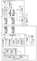
- FIG. 1 is a block diagram illustrating a configuration of an information processing system including a central terminal 1 according to an embodiment of the information processing apparatus of the present invention.
- the information processing system shown in FIG. 1 includes at least a central terminal 1 used by a user, and m peripheral terminals 2-1 to 2-m (m is an arbitrary integer value of 1 or more). Further, the information processing system shown in FIG. 1 includes functional modules 3-1 to 3-m as necessary.
- peripheral terminal 2 when it is not necessary to individually distinguish each of the peripheral terminals 2-1 to 2-m, these are collectively referred to as "peripheral terminal 2".
- functional module 3 When it is not necessary to distinguish the functional modules 3-1 to 3-m individually, these are collectively referred to as “functional module 3”.
- the peripheral terminal 2 is a hardware device used by being connected to the functional module 3, and performs pairing with the central terminal 1 by short-range wireless communication.
- the term “pairing” refers to causing the central terminal 1 to recognize the type and connection state of the peripheral terminal 2 and the functional modules 3 connected thereto using short-range wireless communication.
- the pairing in the BLE refers to a process of registering the advertising packet transmitted from the peripheral terminal 2-K to be wirelessly connected to the central terminal 1 with the central terminal 1 as described above. . In the following description, it is assumed that pairing in BLE is performed.
- the central terminal 1 performs pairing with a predetermined peripheral terminal 2-K (K is an arbitrary integer value from 1 to m), and thereby the peripheral terminal 2-K and the peripheral terminal 2-K are connected to each other. It recognizes the connected predetermined function module 3-K.
- the functional module 3-K is, for example, a hardware device including various sensors such as a temperature sensor, operating instruments such as a buzzer, and driving instruments such as a motor and a fan.
- FIG. 2 is a block diagram showing a hardware configuration of the central terminal 1 of FIG.
- the central terminal 1 is configured by a predetermined hardware device or the like.
- the central terminal 1 includes a CPU (Central Processing Unit) 21, a ROM (Read Only Memory) 22, a RAM (Random Access Memory) 23, a bus 24, an input / output interface 25, a touch operation input unit 26, and a display.
- Unit 27 an input unit 28, a storage unit 29, a first short-range wireless communication unit 30, a second short-range wireless communication unit 31, a communication unit 32, a drive 33, and a removable medium 34. I have.
- the CPU 21 executes various processes according to a program recorded in the ROM 22 or a program loaded from the storage unit 29 to the RAM 23.
- the RAM 23 also appropriately stores information necessary for the CPU 21 to execute various processes.
- the CPU 21, the ROM 22, and the RAM 23 are connected to each other via a bus 24.
- the bus 24 is also connected to an input / output interface 25.
- the input / output interface 25 includes a touch operation input unit 26, a display unit 27, an input unit 28, a storage unit 29, a first short-range wireless communication unit 30, a second short-range wireless communication unit 31, a communication unit 32, and a drive 33. It is connected.
- the touch operation input unit 26 is configured by, for example, a capacitive or resistive (pressure-sensitive) position input sensor stacked on the display unit 27, and detects the coordinates of the position where the touch operation is performed.
- the display unit 27 is configured by a display such as a liquid crystal, and displays various images such as an image related to program creation.
- the touch operation input unit 26 and the display unit 27 constitute a touch panel.
- the input unit 28 is configured by various hardware and the like, and inputs various information according to a user's instruction operation.
- the storage unit 29 includes a hard disk, a DRAM (Dynamic Random Access Memory), and the like, and stores various information.
- the first short-range wireless communication unit 30 executes, for example, control for performing short-range wireless communication by a method according to the NFC (registered trademark) standard.
- the second short-range wireless communication unit 31 executes, for example, control for performing short-range wireless communication by a method according to the standard of BLE (Bluetooth (registered trademark) Low Energy).
- BLE Bluetooth (registered trademark) Low Energy
- the central terminal 1 and the peripheral terminal 2 perform pairing by short-range wireless communication in a method according to the BLE standard.
- the communication unit 32 controls communication performed with another device via the Internet or the like independently of the first short-range wireless communication unit 30 and the second short-range wireless communication unit 31.
- the drive 33 is provided as needed.
- the drive 33 is appropriately equipped with a removable medium 34 made of a magnetic disk, an optical disk, a magneto-optical disk, a semiconductor memory, or the like.
- the program read from the removable medium 34 by the drive 33 is installed in the storage unit 29 as needed. Further, the removable medium 34 can also store various information stored in the storage unit 29 in the same manner as the storage unit 29.
- FIG. 3 is a block diagram showing a hardware configuration of the peripheral terminal 2 according to another embodiment of the information processing apparatus according to the present invention.
- the peripheral terminal 2 is configured by a predetermined hardware device or the like.
- the peripheral terminal 2 includes a CPU 41, a ROM 42, a RAM 43, a bus 44, a first short-range wireless communication unit 45, a second short-range wireless communication unit 46, a connection unit 47, and a power supply unit 48. I have.
- the CPU 41, the ROM 42, the RAM 43, the bus 44, the first short-range wireless communication unit 45, and the second short-range wireless communication unit 46 are basically the same as the configuration of the central terminal 1. Here, the description thereof is omitted.
- connection unit 47 makes a connection with another hardware device (for example, the functional module 3 in FIG. 1).
- the connection method by the connection unit 47 is not particularly limited, and the connection may be performed by a method in accordance with, for example, a LAN (Local Area Network) standard.
- the connection unit 47 receives power supplied from a power supply unit 48 described later and transmits power to another hardware device.
- the power supply unit 48 is a battery such as a battery.
- the power supply unit 48 supplies power to the peripheral terminal 2 and also supplies power to the functional module 3 via the connection unit 47 as appropriate.
- the functional module 3 of the information processing system of FIG. 1 also has the hardware configuration shown in FIG.
- the wireless connection processing refers to processing for wirelessly connecting the peripheral terminal 2 to the central terminal 1.
- FIG. 4 is a functional block diagram showing an example of a functional configuration of the central terminal 1 of FIG. 2 and the peripheral terminal 2 of FIG.
- the pairing unit 101 uses the first short-range wireless communication unit 30 to perform wireless communication with the central terminal 1 as a trigger, and performs pairing between the central terminal 1 and the peripheral terminal 2 via the second short-range wireless communication unit 31. Do.
- the pairing unit 101 includes a reading control unit 111, a detection unit 112, a pairing execution unit 113, and a connection confirmation unit 114.
- the read control unit 111 executes control for reading information (hereinafter, referred to as “individual identification information”) for uniquely identifying one of the peripheral terminals 2-1 to 2-m. Specifically, the reading control unit 111 executes control for reading the individual identification information of one peripheral terminal 2 by NFC (registered trademark) short-range wireless communication via the first short-range wireless communication unit 30.
- individual identification information hereinafter, referred to as “individual identification information”
- NFC registered trademark
- the detection unit 112 detects that the read control unit 111 has read the individual identification information of the peripheral terminal 2.
- the pairing execution unit 113 acquires the advertising packet transmitted from the peripheral terminal 2 by the BLE short-range wireless communication via the second short-range wireless communication unit 31 using the detection by the detection unit 112 as a trigger, and Pairing is performed with one peripheral terminal 2 from which the identification information has been read.
- connection confirmation unit 114 confirms the type and connection status of the peripheral terminal 2 paired with the central terminal 1 and the function module 3 connected thereto.
- the program creation unit 102 receives a user's touch operation and actually creates a program.
- the program causes the function module 3 connected to the paired peripheral terminal 2 to perform a predetermined function.
- the program execution unit 103 extracts a program that the user wants to execute from the programs created by the program creation unit 102 and executes the program. That is, the program execution unit 103 transmits the execution result (command or the like) of the created program to the peripheral terminal 2 and the function module 3, and causes the function module 3 to perform its function.
- the display control unit 104 performs control for displaying various information and the like on the display unit 27.
- the display control unit 104 can execute control to cause the display unit 27 to display the type of the functional module 3 and the connection status confirmed by the connection confirmation unit 114.
- the communication control unit 105 performs control for transmitting various types of information to the peripheral terminal 2 via the first short-range wireless communication unit 30 or the second short-range wireless communication unit 31.
- the pairing unit 201 uses the first short-range wireless communication unit 45 to perform wireless communication with the central terminal 1 as a trigger, and the second short-range wireless communication unit 46 performs communication with the central terminal 1 in BLE. Perform pairing.
- the terminal communication control unit 202 executes control for acquiring various information transmitted from the central terminal 1 via the second short-range wireless communication unit 46.
- the function module communication control unit 203 controls communication with the function module 3 when the peripheral terminal 2 and the function module 3 are connected via the connection unit 47.
- the main control unit 204 performs main control of various processes executed by the peripheral terminal 2.
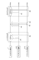
- FIG. 5 is a diagram illustrating a specific example of the pairing performed between the central terminal 1 and the peripheral terminal 2.
- the pairing of the example of FIG. 6 is executed instead of the pairing of the example of FIG.
- white arrows indicate advertising packets.
- pairing is performed by receiving and registering the advertising packet output from the peripheral terminal 2 at the central terminal 1.
- the central terminal 1 performs a scan at a predetermined interval to acquire an advertising packet.
- each of the peripheral terminals 2-1 and 2-2 transmits its own advertising packet.
- the central terminal 1 can perform pairing with the peripheral terminal 2.
- the central terminal 1 An advertising packet is obtained from each of the peripheral terminals 2-1 and 2-2.
- the central terminal 1 can detect that the two peripheral terminals 2-1 and 2-2 are present in the vicinity, but determine which is the peripheral terminal 2-1 and which is the peripheral terminal 2-2. It cannot be determined.
- the user may perform an operation of bringing one of the two peripheral terminals 2-1 and 2-2, for which pairing is desired (for example, the peripheral terminal 2-2), into contact with or close to the central terminal 1.
- the first short-range wireless communication unit 45 of the peripheral terminal 2-2 and the first short-range wireless communication unit 30 of the central terminal 1 perform short-range wireless communication using NFC (registered trademark).
- NFC registered trademark
- Such an event in which short-range wireless communication by NFC (registered trademark) is performed when the central terminal 1 and the peripheral terminal 2 (in this example, the peripheral terminal 2-2) come into contact with or approach each other is referred to as a “touch event”. Call. If the touch event is performed by the peripheral terminal 2-2, the central terminal 1 can determine that the peripheral terminal 2-2 is a pairing target.
- the advertising packet of the peripheral terminal 2-2 is transmitted after the touch event and during the scan of the central terminal 1. Need to be done. Therefore, if the scan timing of the central terminal 1 and the transmission timing of the advertising packet of the peripheral terminal 2-2 do not match well, a pair of the central terminal 1 and the peripheral terminal 2-2 is performed after the touch event is performed. It takes time before the ring is performed. That is, there is a first problem that the time for pairing becomes long.
- the advertising packet transmitted from the peripheral terminal 2-2 by lengthening the scan time by the central terminal 1 or shortening the scan interval. Good.
- the second problem of increased power consumption occurs because the time taken for scanning by the central terminal 1 is increased in total.
- the power consumption can be reduced by shortening the scanning time by the central terminal 1 in total, but the first problem occurs.
- the central terminal 1 may easily acquire the transmitted advertising packet by shortening the interval of transmitting the advertising packet by the peripheral terminal 2-2.
- the second problem of increasing power consumption occurs. If the time taken for pairing is increased to solve the second problem, the number of transmissions by the peripheral terminal 2-2 may be reduced in total, but the first problem occurs.
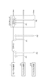
- FIG. 6 is a diagram illustrating a specific example of pairing that solves the pairing problem (a problem in which one of the first problem and the second problem occurs) illustrated in FIG. 5.
- the central terminal 1 starts scanning and the peripheral terminal 2-2 starts transmitting advertising. I do.
- the reading control unit 111 of the central terminal 1 executes control for reading the individual identification information of the peripheral terminal 2-2 that has become the partner of the touch event.
- the central terminal 1 immediately reads the individual identification information of the peripheral terminal 2-2.
- the pairing execution unit 113 starts scanning with the detection as a trigger.
- the pairing unit 201 of the peripheral terminal 2-2 similarly detects that the individual identification information has been read by the central terminal 1 due to a touch event, and transmits an advertising packet with this detection as a trigger. Thereby, the pairing unit 201 of the peripheral terminal 2-2 can immediately receive the advertising packet of the peripheral terminal 2-2 and execute the pairing almost in the same time as the touch event.
- the central terminal 1 is one of the two peripheral terminals 2 (in the example of FIG. 6, the peripheral terminals 2-1 and 2-2) of the same product, the one of the peripheral terminals 2 (the example of FIG. 6).
- the pairing with the peripheral terminal 2-2) can be instantaneously performed almost in time with the touch event. That is, the first problem is solved.
- the central terminal 1 starts scanning by using a touch event as a trigger without performing scanning at regular intervals, it is possible to save power required for scanning.
- the peripheral terminal 2 can start transmitting an advertising packet by using a touch event as a trigger without transmitting a packet at regular intervals, so that transmission of useless advertising packets that are not scanned can be suppressed, thereby saving power. can do. That is, the second problem is solved.
- the central terminal 1 performs only scanning
- the peripheral terminal 2 performs only packet transmission.
- the present invention is not limited to this configuration.
- the central terminal 1 and the peripheral terminal 2 may both be configured to perform both scanning and packet transmission. In this case, pairing can be performed more efficiently.
- the central terminal 1 recognizes the peripheral terminal 2 to be paired, and the event used as a trigger for starting the pairing is short-range wireless communication by NFC (NFC).
- NFC NFC
- a touch event using a combination of a reader and an NFC tag
- the present invention is not limited to this.
- a combination of a camera and a QR code registered trademark
- a combination of a Hall sensor and a magnet or a combination of an acceleration sensor and a vibration motor
- These combinations are combinations in which a trigger can be received in one direction from the former to the latter or from the latter to the former, but it is needless to say that the present invention is not particularly limited to this.
- a combination of an NFC reader and an NFC host card emulation device or a combination of a speaker and a microphone (or a microphone and a speaker) may be adopted. These combinations are combinations that can receive a trigger in both directions from the former to the latter and from the latter to the former.
- the pairing of the central terminal 1 and the peripheral terminal 2 is performed by short-range wireless communication according to the BLE standard, but the present invention is not particularly limited to this.
- the pairing is not limited to the short-range wireless communication, and the pairing may be performed by any means.
- the number of the peripheral terminals 2 and the number of the functional modules 3 are both described as m, but the present invention is not particularly limited to this. That is, the number of the peripheral terminals 2 and the number of the functional modules 3 may be the same or different. That is, s (s is an arbitrary integer of 1 or more) function modules 3 may be connected to one peripheral terminal 2.
- the above-described series of processing can be executed by hardware or can be executed by software.
- the functional configuration of FIG. 4 is merely an example, and is not particularly limited. That is, it suffices that the information processing system has a function capable of executing the above-described series of processing as a whole, and what kind of functional block is used to realize this function is not particularly limited to the example of FIG.
- the location of the functional block is not particularly limited to FIG. 4 and may be arbitrary.
- one functional block may be constituted by hardware alone, may be constituted by software alone, or may be constituted by a combination thereof.
- a program constituting the software is installed in a computer or the like from a network or a recording medium.
- the computer may be a computer embedded in dedicated hardware.
- the computer may be a computer that can execute various functions by installing various programs, for example, a general-purpose smartphone or a personal computer other than a server.
- a recording medium including such a program is not only constituted by a removable medium (not shown) distributed separately from the apparatus main body in order to provide the user with the program, but also a state in which the recording medium is pre-installed in the apparatus main body. And a recording medium provided to the user.
- steps for describing a program recorded on a recording medium are not limited to processing performed in chronological order according to the order, but are not necessarily performed in chronological order, but are performed in parallel or individually. This includes the processing to be executed. Also, in this specification, the term system refers to an entire device including a plurality of devices and a plurality of means.
- the information processing apparatus to which the present invention is applied can adopt various embodiments having the following configurations. That is, the information processing apparatus to which the present invention is applied (for example, the central terminal 1 in FIG. 3) In an information processing apparatus that performs information communication with one or more other information processing apparatuses (for example, the peripheral terminal 2 in FIG. 3) each performing a predetermined function, Among the one or more other information processing devices, information capable of specifying one other information processing device (for example, the peripheral terminal 2-2 in FIG. 6) has been acquired as specific information (for example, the above-described individual identification information).
- a pairing unit (for example, the pairing unit 101 in FIG. 4) that executes pairing with the one other information processing device using the acquired pairing information. Is provided.
- the information processing apparatus to which the present invention is applied (for example, the peripheral terminal 2 in FIG. 3, more specifically, for example, the peripheral terminal 2-2 in FIG. 6)
- An information processing device that performs information communication with another information processing device (for example, the central terminal 1 in FIG. 3) in order to perform a predetermined function,
- Another information processing device for example, the central terminal 1 in FIG. 3
- a pairing unit for example, the pairing unit 201 in FIG. 4
- a pairing unit that executes control for transmitting information necessary for the information processing to the other information processing apparatus as pairing information (for example, the above-described advertising packet) Is provided.
- the pairing can be performed in a short time and with low power consumption after the acquisition of the specific information (the touch event in the example of FIG. 6).
- Program creation 103 a program execution unit, 104, a display control unit, 105, a communication control unit, 111, a read control unit, 112, a detection unit, 113, a pairing execution unit, 114 ... Connection confirmation unit, 201 ... Pairing unit, 202 ... Terminal communication control unit, 203 ... Function module communication control unit, 204 ... Main control unit, 500 ... Advertising DB
Abstract
The present invention enables determination of a pairing partner from among a plurality of devices. In response to acquisition of individual identification information enabling identification of one peripheral terminal 2, from among one or more peripheral terminals 2, a pairing unit 101 of a central terminal 1 starts a process (scanning) for acquiring an advertising packet, which is information transmitted from the one peripheral terminal 2 and which is necessary for pairing, and executes pairing with the peripheral terminal 2 by using the acquired advertising packet. In addition, a pairing unit 201 of the peripheral terminal 2 executes control for transmitting the advertising packet in response to acquisition of individual identification information by the central terminal 2.
Description
本発明は、情報処理装置に関する。
<< The present invention relates to an information processing device.
従来より、有線ケーブルを用いることなく情報処理装置同士を接続して使用する場合には、赤外線通信やBluetooth(登録商標)等の近距離無線通信技術が用いられている。例えば、Bluetooth(登録商標)機器同士を無線接続して使用する場合には、まず「ペアリング」が必要となる。ペアリングでは、Bluetooth(登録商標)機器の無線接続に必要となる情報(以下「アドバタイジングパケット」と呼ぶ)が、無線接続の相手となるBluetooth(登録商標)機器に登録される。これにより、Bluetooth(登録商標)機器の認識が可能になる。
Conventionally, when connecting and using information processing apparatuses without using a wired cable, a short-range wireless communication technique such as infrared communication or Bluetooth (registered trademark) has been used. For example, when Bluetooth (registered trademark) devices are wirelessly connected to each other and used, “pairing” is first required. In pairing, information necessary for wireless connection of a Bluetooth (registered trademark) device (hereinafter, referred to as an “advertising packet”) is registered in a Bluetooth (registered trademark) device that is a wireless connection partner. This enables recognition of Bluetooth (registered trademark) devices.
このような近距離無線通信技術の分野では、近年のIoT(Internet of Things)の拡がりに伴い、消費電力を抑えるための研究・開発が進められている。例えば、通信可能距離が短く通信速度も低速であるが、電池交換なく数年間稼働可能とされるBLE(Bluetooth(登録商標) Low Energy)のような超低消費電力型の無線通信技術も開発されている。例えば、特許文献1には、固有の識別子(IDm)をアドバタイジングパケットに含めてBLEでブロードキャスト通信する情報処理装置についての技術が記載されている。また、特許文献2には、イベントに基づいてBLEを制御する通信装置についての技術が記載されている。
研究 In the field of such short-range wireless communication technology, research and development for suppressing power consumption have been promoted with the spread of IoT (Internet of Things) in recent years. For example, an ultra-low power consumption wireless communication technology such as BLE (Bluetooth (registered trademark) Low Energy), which has a short communicable distance and a low communication speed but can be operated for several years without battery replacement, has also been developed. ing. For example, Patent Literature 1 describes a technology of an information processing apparatus that performs broadcast communication by BLE while including a unique identifier (IDm) in an advertising packet. Further, Patent Literature 2 discloses a technology regarding a communication device that controls BLE based on an event.
しかしながら、従来の技術の場合、BLEにより無線接続の相手となる機器(以下「BLE機器」と呼ぶ)が複数存在する場合には、以下のような問題が生じていた。
即ち、従来の技術の場合、図7に示すように、例えばBLE機器Aに接続しようとするBLE機器B及びCとが存在する場合には、BLE機器B及びCの夫々は、アドバタイジングパケット(図7中白抜き矢印)を一定間隔で送信する。これに対して、BLE機器Aは、送信されたアドバタイジングパケットを取得するためのスキャンを一定間隔で行う。ここで、BLE機器B及びCの夫々のアドバタイジングパケットの送信のタイミングと、BLE機器Aのスキャンのタイミングとが重なると、BLE機器Aは、BLE機器B及びCを検知するので、BLE機器B又はCとのペアリングが可能になる。具体的には、BLE機器Aのスキャンの結果、BLE機器B及びCの夫々に関する情報がBLE機器Aの画面に表示される。そして、BLE機器Aを操作するユーザが、BLE機器AとペアリングすべきBLE機器(B又はC)のうち1台選択すると、選択されたBLE機器(B又はC)とBLE機器Aとの間でペアリングが行われる。 However, in the case of the conventional technology, when there are a plurality of devices (hereinafter, referred to as “BLE devices”) to be wirelessly connected by BLE, the following problem occurs.
That is, in the case of the conventional technology, as shown in FIG. 7, when there are BLE devices B and C to be connected to the BLE device A, for example, each of the BLE devices B and C transmits an advertising packet (see FIG. 7). 7), are transmitted at regular intervals. On the other hand, the BLE device A performs scanning for acquiring the transmitted advertising packet at regular intervals. Here, when the transmission timing of the advertising packet of each of the BLE devices B and C and the scan timing of the BLE device A overlap, the BLE device A detects the BLE devices B and C. Pairing with C becomes possible. Specifically, as a result of the scan of the BLE device A, information on each of the BLE devices B and C is displayed on the screen of the BLE device A. Then, when the user operating the BLE device A selects one of the BLE devices (B or C) to be paired with the BLE device A, the user selects the BLE device (B or C) and the BLE device A. Is performed for pairing.
しかしながら、BLE機器の画面に接続先の候補として表示された複数のBLE機器のプロダクトが同種である場合には、これらを識別することは困難である。例えば、図7に示すBLE機器BのプロダクトとBLE機器Cのプロダクトとが同種である場合には、BLE機器Aの画面に表示された2つのBLE機器に関する情報の夫々がいずれのBLE機器を示す情報であるのかを判別することが困難となる。
However, if the products of a plurality of BLE devices displayed as connection destination candidates on the screen of the BLE device are of the same type, it is difficult to identify them. For example, when the product of the BLE device B and the product of the BLE device C shown in FIG. 7 are the same type, each of the information on the two BLE devices displayed on the screen of the BLE device A indicates which BLE device. It is difficult to determine whether the information is information.
本発明は、このような状況に鑑みてなされたものであり、複数の装置の中からペアリングの相手を判別可能にすることを目的とする。
The present invention has been made in view of such a situation, and an object of the present invention is to make it possible to determine a pairing partner from a plurality of devices.
上記目的を達成するため、本発明の一態様の情報処理装置は、
所定の機能を夫々発揮する1以上の他の情報処理装置に対する情報通信を行う情報処理装置であって、
前記1以上の他の情報処理装置のうち、1の他の情報処理装置を特定可能な情報が特定情報として取得されたことをトリガとして、前記1の他の情報処理装置から送信されるペアリングのために必要な情報をペアリング情報として取得する処理を開始し、取得した当該ペアリング情報を用いて前記1の他の情報処理装置との間のペアリングを実行するペアリング手段、
を備える。 In order to achieve the above object, an information processing device of one embodiment of the present invention
An information processing apparatus for performing information communication with one or more other information processing apparatuses each performing a predetermined function,
Pairing transmitted from the one other information processing device, triggered by the fact that information capable of identifying one other information processing device among the one or more other information processing devices is obtained as the specific information. A pairing unit that starts a process of acquiring information necessary for the device as pairing information, and performs pairing with the one other information processing device using the acquired pairing information;
Is provided.
また、上記目的を達成するため、本発明の別の一態様の情報処理装置は、
所定の機能を発揮するために、他の情報処理装置と情報通信を行う情報処理装置であって、
前記情報処理装置を特定可能な情報が特定情報として前記他の情報処理装置に取得されたことをトリガとして、前記他の情報処理装置において実行されるペアリングのために必要な情報を、ペアリング情報として前記他の情報処理装置に送信する制御を実行するペアリング手段、
を備える。 In order to achieve the above object, an information processing device of another embodiment of the present invention includes:
An information processing device that performs information communication with another information processing device to exhibit a predetermined function,
Triggered by the fact that the information capable of identifying the information processing device is acquired by the other information processing device as the identification information, information necessary for pairing performed in the other information processing device is paired. Pairing means for executing control for transmitting to the other information processing device as information,
Is provided.
本発明によれば、複数の装置の中からペアリングの相手を判別可能にすることができる。
According to the present invention, it is possible to determine a pairing partner from a plurality of devices.
以下、本発明の実施形態について、図面を用いて説明する。
Hereinafter, embodiments of the present invention will be described with reference to the drawings.
[システム構成]
図1は、本発明の情報処理装置の一実施形態に係るセントラル端末1を含む情報処理システムの構成を示すブロック図である。
図1に示す情報処理システムは、ユーザにより使用されるセントラル端末1と、m個のペリフェラル端末2-1乃至2-m(mは1以上の任意の整数値)とを少なくとも含む。また、図1に示す情報処理システムは、必要に応じて機能モジュール3-1乃至3-mを含む。
なお、以下、ペリフェラル端末2-1乃至2-mの夫々を個々に区別する必要がない場合、これらをまとめて「ペリフェラル端末2」と呼ぶ。また、機能モジュール3-1乃至3-mを個々に区別する必要がない場合、これらをまとめて「機能モジュール3」と呼ぶ。 [System configuration]
FIG. 1 is a block diagram illustrating a configuration of an information processing system including a central terminal 1 according to an embodiment of the information processing apparatus of the present invention.
The information processing system shown in FIG. 1 includes at least a central terminal 1 used by a user, and m peripheral terminals 2-1 to 2-m (m is an arbitrary integer value of 1 or more). Further, the information processing system shown in FIG. 1 includes functional modules 3-1 to 3-m as necessary.
Hereinafter, when it is not necessary to individually distinguish each of the peripheral terminals 2-1 to 2-m, these are collectively referred to as "peripheral terminal 2". When it is not necessary to distinguish the functional modules 3-1 to 3-m individually, these are collectively referred to as “functional module 3”.
図1は、本発明の情報処理装置の一実施形態に係るセントラル端末1を含む情報処理システムの構成を示すブロック図である。
図1に示す情報処理システムは、ユーザにより使用されるセントラル端末1と、m個のペリフェラル端末2-1乃至2-m(mは1以上の任意の整数値)とを少なくとも含む。また、図1に示す情報処理システムは、必要に応じて機能モジュール3-1乃至3-mを含む。
なお、以下、ペリフェラル端末2-1乃至2-mの夫々を個々に区別する必要がない場合、これらをまとめて「ペリフェラル端末2」と呼ぶ。また、機能モジュール3-1乃至3-mを個々に区別する必要がない場合、これらをまとめて「機能モジュール3」と呼ぶ。 [System configuration]
FIG. 1 is a block diagram illustrating a configuration of an information processing system including a central terminal 1 according to an embodiment of the information processing apparatus of the present invention.
The information processing system shown in FIG. 1 includes at least a central terminal 1 used by a user, and m peripheral terminals 2-1 to 2-m (m is an arbitrary integer value of 1 or more). Further, the information processing system shown in FIG. 1 includes functional modules 3-1 to 3-m as necessary.
Hereinafter, when it is not necessary to individually distinguish each of the peripheral terminals 2-1 to 2-m, these are collectively referred to as "
ペリフェラル端末2は、機能モジュール3と接続して使用するハードウェアデバイスであり、近距離無線通信でセントラル端末1とのペアリングを行う。
ペアリングとは、端的に言えば、近距離無線通信を用いて、セントラル端末1に、ペリフェラル端末2及びそれに接続されている機能モジュール3の種別や接続状態等を認識させることをいう。
具体的には例えば、BLEでのペアリングとは、上述したように、セントラル端末1に無線接続しようとするペリフェラル端末2-Kから送信されたアドバタイジングパケットを、セントラル端末1に登録させる処理をいう。なお、以下の説明では、BLEでのペアリングが行われるものとする。
つまり、セントラル端末1は、所定のペリフェラル端末2-K(Kは、1乃至mのうち任意の整数値)とペアリングを行うことで、ペリフェラル端2-Kと、当該ペリフェラル端2-Kと接続された所定の機能モジュール3-Kとを認識する。
機能モジュール3-Kとは、例えば、温度センサ等の各種センサ、ブザー等の操作器具、モーターや扇風機等の駆動器具等により構成されるハードウェアデバイスである。 Theperipheral terminal 2 is a hardware device used by being connected to the functional module 3, and performs pairing with the central terminal 1 by short-range wireless communication.
In short, the term “pairing” refers to causing the central terminal 1 to recognize the type and connection state of theperipheral terminal 2 and the functional modules 3 connected thereto using short-range wireless communication.
Specifically, for example, the pairing in the BLE refers to a process of registering the advertising packet transmitted from the peripheral terminal 2-K to be wirelessly connected to the central terminal 1 with the central terminal 1 as described above. . In the following description, it is assumed that pairing in BLE is performed.
That is, the central terminal 1 performs pairing with a predetermined peripheral terminal 2-K (K is an arbitrary integer value from 1 to m), and thereby the peripheral terminal 2-K and the peripheral terminal 2-K are connected to each other. It recognizes the connected predetermined function module 3-K.
The functional module 3-K is, for example, a hardware device including various sensors such as a temperature sensor, operating instruments such as a buzzer, and driving instruments such as a motor and a fan.
ペアリングとは、端的に言えば、近距離無線通信を用いて、セントラル端末1に、ペリフェラル端末2及びそれに接続されている機能モジュール3の種別や接続状態等を認識させることをいう。
具体的には例えば、BLEでのペアリングとは、上述したように、セントラル端末1に無線接続しようとするペリフェラル端末2-Kから送信されたアドバタイジングパケットを、セントラル端末1に登録させる処理をいう。なお、以下の説明では、BLEでのペアリングが行われるものとする。
つまり、セントラル端末1は、所定のペリフェラル端末2-K(Kは、1乃至mのうち任意の整数値)とペアリングを行うことで、ペリフェラル端2-Kと、当該ペリフェラル端2-Kと接続された所定の機能モジュール3-Kとを認識する。
機能モジュール3-Kとは、例えば、温度センサ等の各種センサ、ブザー等の操作器具、モーターや扇風機等の駆動器具等により構成されるハードウェアデバイスである。 The
In short, the term “pairing” refers to causing the central terminal 1 to recognize the type and connection state of the
Specifically, for example, the pairing in the BLE refers to a process of registering the advertising packet transmitted from the peripheral terminal 2-K to be wirelessly connected to the central terminal 1 with the central terminal 1 as described above. . In the following description, it is assumed that pairing in BLE is performed.
That is, the central terminal 1 performs pairing with a predetermined peripheral terminal 2-K (K is an arbitrary integer value from 1 to m), and thereby the peripheral terminal 2-K and the peripheral terminal 2-K are connected to each other. It recognizes the connected predetermined function module 3-K.
The functional module 3-K is, for example, a hardware device including various sensors such as a temperature sensor, operating instruments such as a buzzer, and driving instruments such as a motor and a fan.
[ハードウェア構成]
図2は、図1のセントラル端末1のハードウェア構成を示すブロック図である。 [Hardware configuration]
FIG. 2 is a block diagram showing a hardware configuration of the central terminal 1 of FIG.
図2は、図1のセントラル端末1のハードウェア構成を示すブロック図である。 [Hardware configuration]
FIG. 2 is a block diagram showing a hardware configuration of the central terminal 1 of FIG.
セントラル端末1は、所定のハードウェアデバイス等で構成される。
セントラル端末1は、CPU(Central Processing Unit)21と、ROM(Read Only Memory)22と、RAM(Random Access Memory)23と、バス24と、入出力インターフェース25と、タッチ操作入力部26と、表示部27と、入力部28と、記憶部29と、第一近距離無線通信部30と、第二近距離無線通信部31と、通信部32と、ドライブ33と、リムーバブルメディア34とを備えている。 The central terminal 1 is configured by a predetermined hardware device or the like.
The central terminal 1 includes a CPU (Central Processing Unit) 21, a ROM (Read Only Memory) 22, a RAM (Random Access Memory) 23, abus 24, an input / output interface 25, a touch operation input unit 26, and a display. Unit 27, an input unit 28, a storage unit 29, a first short-range wireless communication unit 30, a second short-range wireless communication unit 31, a communication unit 32, a drive 33, and a removable medium 34. I have.
セントラル端末1は、CPU(Central Processing Unit)21と、ROM(Read Only Memory)22と、RAM(Random Access Memory)23と、バス24と、入出力インターフェース25と、タッチ操作入力部26と、表示部27と、入力部28と、記憶部29と、第一近距離無線通信部30と、第二近距離無線通信部31と、通信部32と、ドライブ33と、リムーバブルメディア34とを備えている。 The central terminal 1 is configured by a predetermined hardware device or the like.
The central terminal 1 includes a CPU (Central Processing Unit) 21, a ROM (Read Only Memory) 22, a RAM (Random Access Memory) 23, a
CPU21は、ROM22に記録されているプログラム、又は、記憶部29からRAM23にロードされたプログラムに従って各種の処理を実行する。
RAM23には、CPU21が各種の処理を実行する上において必要な情報等も適宜記憶される。 TheCPU 21 executes various processes according to a program recorded in the ROM 22 or a program loaded from the storage unit 29 to the RAM 23.
TheRAM 23 also appropriately stores information necessary for the CPU 21 to execute various processes.
RAM23には、CPU21が各種の処理を実行する上において必要な情報等も適宜記憶される。 The
The
CPU21、ROM22及びRAM23は、バス24を介して相互に接続されている。このバス24にはまた、入出力インターフェース25も接続されている。入出力インターフェース25には、タッチ操作入力部26、表示部27、入力部28、記憶部29、第一近距離無線通信部30、第二近距離無線通信部31、通信部32及びドライブ33が接続されている。
The CPU 21, the ROM 22, and the RAM 23 are connected to each other via a bus 24. The bus 24 is also connected to an input / output interface 25. The input / output interface 25 includes a touch operation input unit 26, a display unit 27, an input unit 28, a storage unit 29, a first short-range wireless communication unit 30, a second short-range wireless communication unit 31, a communication unit 32, and a drive 33. It is connected.
タッチ操作入力部26は、例えば表示部27に積層される静電容量式又は抵抗膜式(感圧式)の位置入力センサにより構成され、タッチ操作がなされた位置の座標を検出する。
表示部27は、液晶等のディスプレイにより構成され、プログラム作製に関する画像等、各種画像を表示する。
このように、本実施形態では、タッチ操作入力部26と表示部27とにより、タッチパネルが構成されている。 The touchoperation input unit 26 is configured by, for example, a capacitive or resistive (pressure-sensitive) position input sensor stacked on the display unit 27, and detects the coordinates of the position where the touch operation is performed.
Thedisplay unit 27 is configured by a display such as a liquid crystal, and displays various images such as an image related to program creation.
Thus, in the present embodiment, the touchoperation input unit 26 and the display unit 27 constitute a touch panel.
表示部27は、液晶等のディスプレイにより構成され、プログラム作製に関する画像等、各種画像を表示する。
このように、本実施形態では、タッチ操作入力部26と表示部27とにより、タッチパネルが構成されている。 The touch
The
Thus, in the present embodiment, the touch
入力部28は、各種ハードウェア等で構成され、ユーザの指示操作に応じて各種情報を入力する。
記憶部29は、ハードディスクやDRAM(Dynamic Random Access Memory)等で構成され、各種情報を記憶する。
第一近距離無線通信部30は、例えば、NFC(登録商標)の規格に従った方式で近距離無線通信を行う制御を実行する。
第二近距離無線通信部31は、例えば、BLE(Bluetooth(登録商標) Low Energy)の規格に従った方式で近距離無線通信を行う制御を実行する。本実施形態では上述の通り、セントラル端末1とペリフェラル端末2は、BLEの規格に従った方式で近距離無線通信によってペアリングを行う。
通信部32は、第一近距離無線通信部30及び第二近距離無線通信部31とは別個独立して、インターネット等を介して他の装置との間で行う通信を制御する。 Theinput unit 28 is configured by various hardware and the like, and inputs various information according to a user's instruction operation.
Thestorage unit 29 includes a hard disk, a DRAM (Dynamic Random Access Memory), and the like, and stores various information.
The first short-rangewireless communication unit 30 executes, for example, control for performing short-range wireless communication by a method according to the NFC (registered trademark) standard.
The second short-rangewireless communication unit 31 executes, for example, control for performing short-range wireless communication by a method according to the standard of BLE (Bluetooth (registered trademark) Low Energy). In the present embodiment, as described above, the central terminal 1 and the peripheral terminal 2 perform pairing by short-range wireless communication in a method according to the BLE standard.
Thecommunication unit 32 controls communication performed with another device via the Internet or the like independently of the first short-range wireless communication unit 30 and the second short-range wireless communication unit 31.
記憶部29は、ハードディスクやDRAM(Dynamic Random Access Memory)等で構成され、各種情報を記憶する。
第一近距離無線通信部30は、例えば、NFC(登録商標)の規格に従った方式で近距離無線通信を行う制御を実行する。
第二近距離無線通信部31は、例えば、BLE(Bluetooth(登録商標) Low Energy)の規格に従った方式で近距離無線通信を行う制御を実行する。本実施形態では上述の通り、セントラル端末1とペリフェラル端末2は、BLEの規格に従った方式で近距離無線通信によってペアリングを行う。
通信部32は、第一近距離無線通信部30及び第二近距離無線通信部31とは別個独立して、インターネット等を介して他の装置との間で行う通信を制御する。 The
The
The first short-range
The second short-range
The
ドライブ33は、必要に応じて設けられる。ドライブ33には、磁気ディスク、光ディスク、光磁気ディスク、或いは半導体メモリ等よりなる、リムーバブルメディア34が適宜装着される。ドライブ33によってリムーバブルメディア34から読み出されたプログラムは、必要に応じて記憶部29にインストールされる。
また、リムーバブルメディア34は、記憶部29に記憶されている各種情報も、記憶部29と同様に記憶することができる。 Thedrive 33 is provided as needed. The drive 33 is appropriately equipped with a removable medium 34 made of a magnetic disk, an optical disk, a magneto-optical disk, a semiconductor memory, or the like. The program read from the removable medium 34 by the drive 33 is installed in the storage unit 29 as needed.
Further, the removable medium 34 can also store various information stored in thestorage unit 29 in the same manner as the storage unit 29.
また、リムーバブルメディア34は、記憶部29に記憶されている各種情報も、記憶部29と同様に記憶することができる。 The
Further, the removable medium 34 can also store various information stored in the
図3は、本発明における他の情報処理装置の一実施形態に係るペリフェラル端末2のハードウェア構成を示すブロック図である。
FIG. 3 is a block diagram showing a hardware configuration of the peripheral terminal 2 according to another embodiment of the information processing apparatus according to the present invention.
ペリフェラル端末2は、所定のハードウェアデバイス等で構成される。
ペリフェラル端末2は、CPU41と、ROM42と、RAM43と、バス44と、第一近距離無線通信部45と、第二近距離無線通信部46と、接続部47と、電源部48とを備えている。 Theperipheral terminal 2 is configured by a predetermined hardware device or the like.
Theperipheral terminal 2 includes a CPU 41, a ROM 42, a RAM 43, a bus 44, a first short-range wireless communication unit 45, a second short-range wireless communication unit 46, a connection unit 47, and a power supply unit 48. I have.
ペリフェラル端末2は、CPU41と、ROM42と、RAM43と、バス44と、第一近距離無線通信部45と、第二近距離無線通信部46と、接続部47と、電源部48とを備えている。 The
The
ペリフェラル端末2の構成のうち、CPU41、ROM42、RAM43、バス44、第一近距離無線通信部45、第二近距離無線通信部46については、セントラル端末1の構成と基本的に同様であるので、ここではそれらの説明は省略する。
Of the configuration of the peripheral terminal 2, the CPU 41, the ROM 42, the RAM 43, the bus 44, the first short-range wireless communication unit 45, and the second short-range wireless communication unit 46 are basically the same as the configuration of the central terminal 1. Here, the description thereof is omitted.
接続部47は、他のハードウェアデバイス(例えば、図1の機能モジュール3)との間で接続を行う。なお、接続部47による接続の方式は特に限定されず、例えばLAN(Local Area Network)の規格に従った方式による接続がなされてもよい。接続部47は、後述する電源部48からの電力の供給を受けて、他のハードウェアデバイスに電力を伝達する。
電源部48は、電池等のバッテリーである。電源部48は、ペリフェラル端末2に電力を供給するとともに、接続部47を介して、適宜、機能モジュール3に電力を供給する。 Theconnection unit 47 makes a connection with another hardware device (for example, the functional module 3 in FIG. 1). Note that the connection method by the connection unit 47 is not particularly limited, and the connection may be performed by a method in accordance with, for example, a LAN (Local Area Network) standard. The connection unit 47 receives power supplied from a power supply unit 48 described later and transmits power to another hardware device.
Thepower supply unit 48 is a battery such as a battery. The power supply unit 48 supplies power to the peripheral terminal 2 and also supplies power to the functional module 3 via the connection unit 47 as appropriate.
電源部48は、電池等のバッテリーである。電源部48は、ペリフェラル端末2に電力を供給するとともに、接続部47を介して、適宜、機能モジュール3に電力を供給する。 The
The
なお、図示はしないが、図1の情報処理システムのうち、機能モジュール3も、図3に示すハードウェア構成を有している。
Although not shown, the functional module 3 of the information processing system of FIG. 1 also has the hardware configuration shown in FIG.
このようなセントラル端末1及びペリフェラル端末2の各種ハードウェアと各種ソフトウェアの協働により無線接続処理の実行が可能となる。ここで、無線接続処理とは、セントラル端末1にペリフェラル端末2を無線接続する処理をいう。
(4) The cooperation of various kinds of hardware and software of the central terminal 1 and the peripheral terminal 2 makes it possible to execute a wireless connection process. Here, the wireless connection processing refers to processing for wirelessly connecting the peripheral terminal 2 to the central terminal 1.
[機能的構成]
セントラル端末1及びペリフェラル端末2は、上述の無線接続処理を実現すべく、図4に示すような機能的構成を有している。
図4は、図2のセントラル端末1及び図3のペリフェラル端末2の機能的構成の一例を示す機能ブロック図である。 [Functional configuration]
The central terminal 1 and theperipheral terminal 2 have a functional configuration as shown in FIG. 4 in order to realize the above-described wireless connection processing.
FIG. 4 is a functional block diagram showing an example of a functional configuration of the central terminal 1 of FIG. 2 and theperipheral terminal 2 of FIG.
セントラル端末1及びペリフェラル端末2は、上述の無線接続処理を実現すべく、図4に示すような機能的構成を有している。
図4は、図2のセントラル端末1及び図3のペリフェラル端末2の機能的構成の一例を示す機能ブロック図である。 [Functional configuration]
The central terminal 1 and the
FIG. 4 is a functional block diagram showing an example of a functional configuration of the central terminal 1 of FIG. 2 and the
(セントラル端末)
図4に示すように、セントラル端末1のCPU21において無線接続処理が実行される場合には、ペアリング部101と、表示制御部104と、通信制御部105とが機能する。また、セントラル端末1の記憶部29の一領域には、アドバタイジングDB500が設けられている。 (Central terminal)
As shown in FIG. 4, when theCPU 21 of the central terminal 1 executes the wireless connection processing, the pairing unit 101, the display control unit 104, and the communication control unit 105 function. In one area of the storage unit 29 of the central terminal 1, an advertising DB 500 is provided.
図4に示すように、セントラル端末1のCPU21において無線接続処理が実行される場合には、ペアリング部101と、表示制御部104と、通信制御部105とが機能する。また、セントラル端末1の記憶部29の一領域には、アドバタイジングDB500が設けられている。 (Central terminal)
As shown in FIG. 4, when the
ペアリング部101は、第一近距離無線通信部30によるセントラル端末1との無線通信をトリガとして、第二近距離無線通信部31を介して、セントラル端末1とペリフェラル端末2とのペアリングを行う。
ペアリング部101は、読取制御部111と、検知部112と、ペアリング実行部113と、接続確認部114とを備える。 Thepairing unit 101 uses the first short-range wireless communication unit 30 to perform wireless communication with the central terminal 1 as a trigger, and performs pairing between the central terminal 1 and the peripheral terminal 2 via the second short-range wireless communication unit 31. Do.
Thepairing unit 101 includes a reading control unit 111, a detection unit 112, a pairing execution unit 113, and a connection confirmation unit 114.
ペアリング部101は、読取制御部111と、検知部112と、ペアリング実行部113と、接続確認部114とを備える。 The
The
読取制御部111は、ペリフェラル端末2-1乃至2-mのうち、1のペリフェラル端末2を一意に特定するための情報(以下「個体識別情報」と呼ぶ)を読み取る制御を実行する。具体的には、読取制御部111は、第一近距離無線通信部30を介するNFC(登録商標)での近距離無線通信によって、1のペリフェラル端末2の個体識別情報を読み取る制御を実行する。
The read control unit 111 executes control for reading information (hereinafter, referred to as “individual identification information”) for uniquely identifying one of the peripheral terminals 2-1 to 2-m. Specifically, the reading control unit 111 executes control for reading the individual identification information of one peripheral terminal 2 by NFC (registered trademark) short-range wireless communication via the first short-range wireless communication unit 30.
検知部112は、読取制御部111によりペリフェラル端末2の個体識別情報が読み取られたことを検知する。
The detection unit 112 detects that the read control unit 111 has read the individual identification information of the peripheral terminal 2.
ペアリング実行部113は、検知部112による検知をトリガとして、BLEによる近距離無線通信でペリフェラル端末2から送信されたアドバタイジングパケットを、第二近距離無線通信部31を介して取得して、固体識別情報が読み取られた1のペリフェラル端末2との間のペアリングを実行する。
The pairing execution unit 113 acquires the advertising packet transmitted from the peripheral terminal 2 by the BLE short-range wireless communication via the second short-range wireless communication unit 31 using the detection by the detection unit 112 as a trigger, and Pairing is performed with one peripheral terminal 2 from which the identification information has been read.
接続確認部114は、セントラル端末1とペアリングしたペリフェラル端末2、及びそれに接続された機能モジュール3の種別や接続の状況を確認する。
The connection confirmation unit 114 confirms the type and connection status of the peripheral terminal 2 paired with the central terminal 1 and the function module 3 connected thereto.
プログラム作製部102は、ユーザのタッチ操作を受付けて、実際にプログラムの作製を行う。ここで、プログラムとしては、ペアリングされたペリフェラル端末2に接続された機能モジュール3に対して所定の機能を発揮させるものである。
プログラム実行部103は、プログラム作製部102により作製されたプログラムのうちから、ユーザが実行を望むプログラムを抽出して実行する。即ち、プログラム実行部103は、作製されたプログラムの実行結果(コマンド等)を、ペリフェラル端末2及び機能モジュール3へと送信し、機能モジュール3に機能を発揮させる。 Theprogram creation unit 102 receives a user's touch operation and actually creates a program. Here, the program causes the function module 3 connected to the paired peripheral terminal 2 to perform a predetermined function.
Theprogram execution unit 103 extracts a program that the user wants to execute from the programs created by the program creation unit 102 and executes the program. That is, the program execution unit 103 transmits the execution result (command or the like) of the created program to the peripheral terminal 2 and the function module 3, and causes the function module 3 to perform its function.
プログラム実行部103は、プログラム作製部102により作製されたプログラムのうちから、ユーザが実行を望むプログラムを抽出して実行する。即ち、プログラム実行部103は、作製されたプログラムの実行結果(コマンド等)を、ペリフェラル端末2及び機能モジュール3へと送信し、機能モジュール3に機能を発揮させる。 The
The
表示制御部104は、各種情報等を表示部27に表示するための制御を実行する。例えば、表示制御部104は、接続確認部114に確認された機能モジュール3の種別や接続の状況を表示部27に表示させる制御を実行することもできる。
The display control unit 104 performs control for displaying various information and the like on the display unit 27. For example, the display control unit 104 can execute control to cause the display unit 27 to display the type of the functional module 3 and the connection status confirmed by the connection confirmation unit 114.
通信制御部105は、各種情報を第一近距離無線通信部30又は第二近距離無線通信部31を介してペリフェラル端末2に送信するための制御等を行う。
The communication control unit 105 performs control for transmitting various types of information to the peripheral terminal 2 via the first short-range wireless communication unit 30 or the second short-range wireless communication unit 31.
(ペリフェラル端末)
図4に示すように、ペリフェラル端末2のCPU41において無線接続処理が実行される場合には、ペアリング部201と、端末通信制御部202と、機能モジュール通信制御部203と、主制御部204とが機能する。
ペアリング部201は、第一近距離無線通信部45によるセントラル端末1との無線通信が行われたことをトリガとして、第二近距離無線通信部46によるBLEでのセントラル端末1との間のペアリングを行う。 (Peripheral terminal)
As shown in FIG. 4, when a wireless connection process is executed in theCPU 41 of the peripheral terminal 2, the pairing unit 201, the terminal communication control unit 202, the function module communication control unit 203, and the main control unit 204 Works.
Thepairing unit 201 uses the first short-range wireless communication unit 45 to perform wireless communication with the central terminal 1 as a trigger, and the second short-range wireless communication unit 46 performs communication with the central terminal 1 in BLE. Perform pairing.
図4に示すように、ペリフェラル端末2のCPU41において無線接続処理が実行される場合には、ペアリング部201と、端末通信制御部202と、機能モジュール通信制御部203と、主制御部204とが機能する。
ペアリング部201は、第一近距離無線通信部45によるセントラル端末1との無線通信が行われたことをトリガとして、第二近距離無線通信部46によるBLEでのセントラル端末1との間のペアリングを行う。 (Peripheral terminal)
As shown in FIG. 4, when a wireless connection process is executed in the
The
端末通信制御部202は、セントラル端末1から送信されてきた各種情報を第二近距離無線通信部46を介して取得するための制御等を実行する。
(4) The terminal communication control unit 202 executes control for acquiring various information transmitted from the central terminal 1 via the second short-range wireless communication unit 46.
機能モジュール通信制御部203は、ペリフェラル端末2と機能モジュール3とが接続部47を介して接続されている場合に、機能モジュール3との通信の制御を実行する。
The function module communication control unit 203 controls communication with the function module 3 when the peripheral terminal 2 and the function module 3 are connected via the connection unit 47.
主制御部204は、ペリフェラル端末2で実行される各種処理の主たる制御を実行する。
(4) The main control unit 204 performs main control of various processes executed by the peripheral terminal 2.
次に、図4に示す機能的構成を有するセントラル端末1とペリフェラル端末2との間で行われるペアリングの詳細について説明する。
図5は、セントラル端末1とペリフェラル端末2との間で行われるペアリングの具体例を示す図である。なお、本実施形態では、後述するように、図5の例のペアリングではなく、図6の例のペアリングが実行される。
図5において、白抜き矢印は、アドバタイジングパケットを示している。上述したように、BLEでは、ペリフェラル端末2から出力されるアドバタイジングパケットが、セントラル端末1で受信され登録されることで、ペアリングが行われる。 Next, details of the pairing performed between the central terminal 1 and theperipheral terminal 2 having the functional configuration shown in FIG. 4 will be described.
FIG. 5 is a diagram illustrating a specific example of the pairing performed between the central terminal 1 and theperipheral terminal 2. In the present embodiment, as described later, the pairing of the example of FIG. 6 is executed instead of the pairing of the example of FIG.
In FIG. 5, white arrows indicate advertising packets. As described above, in the BLE, pairing is performed by receiving and registering the advertising packet output from theperipheral terminal 2 at the central terminal 1.
図5は、セントラル端末1とペリフェラル端末2との間で行われるペアリングの具体例を示す図である。なお、本実施形態では、後述するように、図5の例のペアリングではなく、図6の例のペアリングが実行される。
図5において、白抜き矢印は、アドバタイジングパケットを示している。上述したように、BLEでは、ペリフェラル端末2から出力されるアドバタイジングパケットが、セントラル端末1で受信され登録されることで、ペアリングが行われる。 Next, details of the pairing performed between the central terminal 1 and the
FIG. 5 is a diagram illustrating a specific example of the pairing performed between the central terminal 1 and the
In FIG. 5, white arrows indicate advertising packets. As described above, in the BLE, pairing is performed by receiving and registering the advertising packet output from the
図5の例では、セントラル端末1は、アドバタイジングパケットを取得するためのスキャンを所定の間隔で行う。その一方で、ペリフェラル端末2-1及び2-2の夫々は、自身のアドバタイジングパケットを送信する。
セントラル端末1によるスキャンのタイミングと、ペリフェラル端末2によるアドバタイジングパケットの送信のタイミングとが重なった場合、セントラル端末1は、当該ペリフェラル端末2とペアリングを行うことができる。
しかしながら、図5に示すように、セントラル端末1におけるスキャンの期間内に、2台のペリフェラル端末2-1及び2-2の夫々からアドバタイジングパケットが送信されたような場合、セントラル端末1は、2台のペリフェラル端末2-1及び2-2の夫々からアドバタイジングパケットを取得する。この時点では、セントラル端末1は、2台のペリフェラル端末2-1及び2-2が近傍に存在することは検知できるものの、どちらがペリフェラル端末2-1で、どちらがペリフェラル端末2-2であるのかについて判別することはできない。 In the example of FIG. 5, the central terminal 1 performs a scan at a predetermined interval to acquire an advertising packet. On the other hand, each of the peripheral terminals 2-1 and 2-2 transmits its own advertising packet.
When the timing of scanning by the central terminal 1 and the timing of transmitting an advertising packet by theperipheral terminal 2 overlap, the central terminal 1 can perform pairing with the peripheral terminal 2.
However, as shown in FIG. 5, when the advertising packet is transmitted from each of the two peripheral terminals 2-1 and 2-2 during the scan period of the central terminal 1, the central terminal 1 An advertising packet is obtained from each of the peripheral terminals 2-1 and 2-2. At this point, the central terminal 1 can detect that the two peripheral terminals 2-1 and 2-2 are present in the vicinity, but determine which is the peripheral terminal 2-1 and which is the peripheral terminal 2-2. It cannot be determined.
セントラル端末1によるスキャンのタイミングと、ペリフェラル端末2によるアドバタイジングパケットの送信のタイミングとが重なった場合、セントラル端末1は、当該ペリフェラル端末2とペアリングを行うことができる。
しかしながら、図5に示すように、セントラル端末1におけるスキャンの期間内に、2台のペリフェラル端末2-1及び2-2の夫々からアドバタイジングパケットが送信されたような場合、セントラル端末1は、2台のペリフェラル端末2-1及び2-2の夫々からアドバタイジングパケットを取得する。この時点では、セントラル端末1は、2台のペリフェラル端末2-1及び2-2が近傍に存在することは検知できるものの、どちらがペリフェラル端末2-1で、どちらがペリフェラル端末2-2であるのかについて判別することはできない。 In the example of FIG. 5, the central terminal 1 performs a scan at a predetermined interval to acquire an advertising packet. On the other hand, each of the peripheral terminals 2-1 and 2-2 transmits its own advertising packet.
When the timing of scanning by the central terminal 1 and the timing of transmitting an advertising packet by the
However, as shown in FIG. 5, when the advertising packet is transmitted from each of the two peripheral terminals 2-1 and 2-2 during the scan period of the central terminal 1, the central terminal 1 An advertising packet is obtained from each of the peripheral terminals 2-1 and 2-2. At this point, the central terminal 1 can detect that the two peripheral terminals 2-1 and 2-2 are present in the vicinity, but determine which is the peripheral terminal 2-1 and which is the peripheral terminal 2-2. It cannot be determined.
そこで、ユーザは、2台のペリフェラル端末2-1及び2-2のうちペアリングを望む方(例えばペリフェラル端末2-2とする)を、セントラル端末1に接触又は近接させる動作を行うとよい。この場合、ペリフェラル端末2-2の第1近距離無線通信部45と、セントラル端末1の第一近距離無線通信部30とは、NFC(登録商標)による近距離無線通信を行う。このようなセントラル端末1とペリフェラル端末2(本例ではペリフェラル端末2-2)とが接触又は近接することによりNFC(登録商標)による近距離無線通信が行われるイベントを、以下、「タッチイベント」と呼ぶ。ペリフェラル端末2-2によるタッチイベントが行われれば、セントラル端末1は、ペリフェラル端末2-2がペアリング対象であることを判別することができる。
Therefore, the user may perform an operation of bringing one of the two peripheral terminals 2-1 and 2-2, for which pairing is desired (for example, the peripheral terminal 2-2), into contact with or close to the central terminal 1. In this case, the first short-range wireless communication unit 45 of the peripheral terminal 2-2 and the first short-range wireless communication unit 30 of the central terminal 1 perform short-range wireless communication using NFC (registered trademark). Such an event in which short-range wireless communication by NFC (registered trademark) is performed when the central terminal 1 and the peripheral terminal 2 (in this example, the peripheral terminal 2-2) come into contact with or approach each other is referred to as a “touch event”. Call. If the touch event is performed by the peripheral terminal 2-2, the central terminal 1 can determine that the peripheral terminal 2-2 is a pairing target.
ただし、セントラル端末1とペリフェラル端末2-2とのペアリングを行うためには、このタッチイベントの後であってセントラル端末1のスキャンの間に、ペリフェラル端末2-2のアドバイタイジングパケットが送信される必要がある。
したがって、セントラル端末1のスキャンタイミングと、ペリフェラル端末2-2のアドバイタイジングパケットの送信タイミングとがうまく一致しないと、タッチイベントが行われてから、セントラル端末1とペリフェラル端末2-2とのペアリングが行われるまでに、時間を要してしまうことになる。つまり、ペアリングの時間が長くなってしまうという第1問題が生じる。 However, in order to perform pairing between the central terminal 1 and the peripheral terminal 2-2, the advertising packet of the peripheral terminal 2-2 is transmitted after the touch event and during the scan of the central terminal 1. Need to be done.
Therefore, if the scan timing of the central terminal 1 and the transmission timing of the advertising packet of the peripheral terminal 2-2 do not match well, a pair of the central terminal 1 and the peripheral terminal 2-2 is performed after the touch event is performed. It takes time before the ring is performed. That is, there is a first problem that the time for pairing becomes long.
そこで、第1問題を解消すべく、セントラル端末1によるスキャンの時間を長くするか、又はスキャンの間隔を短くすることで、ペリフェラル端末2-2から送信されるアドバタイジングパケットを取得し易くしてもよい。しかしながら、この場合、セントラル端末1によるスキャンの時間がトータルで長くなるため、消費電力が増大してしまうという第2問題が生ずる。
この第2問題を解消すべく、セントラル端末1によるスキャンの時間をトータルで短縮させることで消費電力を下げることができるが、逆に第1問題が生じてしまう。 Therefore, in order to solve the first problem, it is possible to easily obtain the advertising packet transmitted from the peripheral terminal 2-2 by lengthening the scan time by the central terminal 1 or shortening the scan interval. Good. However, in this case, the second problem of increased power consumption occurs because the time taken for scanning by the central terminal 1 is increased in total.
In order to solve the second problem, the power consumption can be reduced by shortening the scanning time by the central terminal 1 in total, but the first problem occurs.
また、第1問題を解消すべく、ペリフェラル端末2-2によるアドバタイジングパケットの送信の間隔を短くすることで、送信されたアドバタイジングパケットをセントラル端末1が取得し易くしてもよい。しかしながら、ペリフェラル端末2-2による送信する回数がトータルで多くなるため、消費電力が増大してしまうという第2問題が生じてしまう。
この第2問題を解消すべく、ペアリングにかける時間を長くすれば、ペリフェラル端末2-2による送信する回数がトータルで少なくしてもよいが、逆に第1問題が生じてしまう。 Further, in order to solve the first problem, the central terminal 1 may easily acquire the transmitted advertising packet by shortening the interval of transmitting the advertising packet by the peripheral terminal 2-2. However, since the number of times of transmission by the peripheral terminal 2-2 increases in total, the second problem of increasing power consumption occurs.
If the time taken for pairing is increased to solve the second problem, the number of transmissions by the peripheral terminal 2-2 may be reduced in total, but the first problem occurs.
そこで、このような第1問題と第2問題を同時に解消すべく、本実施形態では、図6の例のペアリングが行われている。
図6は、図5に示すペアリングの問題点(第1問題及び第2問題の何れか一方が生じてしまう問題点)を解消するペアリングの具体例を示す図である。 Therefore, in order to solve such a first problem and a second problem at the same time, in the present embodiment, the pairing in the example of FIG. 6 is performed.
FIG. 6 is a diagram illustrating a specific example of pairing that solves the pairing problem (a problem in which one of the first problem and the second problem occurs) illustrated in FIG. 5.
図6に示すように、セントラル端末1とペリフェラル端末2-2とによるタッチイベントが行われたことをトリガとして、セントラル端末1はスキャンを開始すると共に、ペリフェラル端末2-2はアドバタイジングの送信を開始する。
具体的には、セントラル端末1の読取制御部111が、タッチイベントの相手となったペリフェラル端末2-2の個体識別情報を読み取る制御を実行する。これにより、セントラル端末1は、ペリフェラル端末2-2の個体識別情報を即座に読み取る。
このとき、セントラル端末1の検知部112は、ペリフェラル端末2-2の個体識別情報が読み取られたことを検知するので、ペアリング実行部113は、この検知をトリガとしてスキャンを開始する。
これと略同時に、ペリフェラル端末2-2のペアリング部201は、同様に、タッチイベントにより固体識別情報がセントラル端末1に読み取られたことを検知し、この検知をトリガとしてアドバタイジングパケットを送信する。
これにより、ペリフェラル端末2-2のペアリング部201は、タッチイベントと時間的に略同一に、ペリフェラル端末2-2のアドバタイジングパケットを即座に受信して、ペアリングを実行することができる。 As shown in FIG. 6, triggered by the touch event performed by the central terminal 1 and the peripheral terminal 2-2, the central terminal 1 starts scanning and the peripheral terminal 2-2 starts transmitting advertising. I do.
Specifically, thereading control unit 111 of the central terminal 1 executes control for reading the individual identification information of the peripheral terminal 2-2 that has become the partner of the touch event. As a result, the central terminal 1 immediately reads the individual identification information of the peripheral terminal 2-2.
At this time, since thedetection unit 112 of the central terminal 1 detects that the individual identification information of the peripheral terminal 2-2 has been read, the pairing execution unit 113 starts scanning with the detection as a trigger.
At substantially the same time, thepairing unit 201 of the peripheral terminal 2-2 similarly detects that the individual identification information has been read by the central terminal 1 due to a touch event, and transmits an advertising packet with this detection as a trigger.
Thereby, thepairing unit 201 of the peripheral terminal 2-2 can immediately receive the advertising packet of the peripheral terminal 2-2 and execute the pairing almost in the same time as the touch event.
具体的には、セントラル端末1の読取制御部111が、タッチイベントの相手となったペリフェラル端末2-2の個体識別情報を読み取る制御を実行する。これにより、セントラル端末1は、ペリフェラル端末2-2の個体識別情報を即座に読み取る。
このとき、セントラル端末1の検知部112は、ペリフェラル端末2-2の個体識別情報が読み取られたことを検知するので、ペアリング実行部113は、この検知をトリガとしてスキャンを開始する。
これと略同時に、ペリフェラル端末2-2のペアリング部201は、同様に、タッチイベントにより固体識別情報がセントラル端末1に読み取られたことを検知し、この検知をトリガとしてアドバタイジングパケットを送信する。
これにより、ペリフェラル端末2-2のペアリング部201は、タッチイベントと時間的に略同一に、ペリフェラル端末2-2のアドバタイジングパケットを即座に受信して、ペアリングを実行することができる。 As shown in FIG. 6, triggered by the touch event performed by the central terminal 1 and the peripheral terminal 2-2, the central terminal 1 starts scanning and the peripheral terminal 2-2 starts transmitting advertising. I do.
Specifically, the
At this time, since the
At substantially the same time, the
Thereby, the
このようにして、セントラル端末1は、プロダクトが同種である2台のペリフェラル端末2(図6の例ではペリフェラル端末2-1及び2-2)のうち1台のペリフェラル端末2(図6の例ではペリフェラル端末2-2)との間でペアリングを、タッチイベントと時間的に略同一に即座に行うことができる。即ち、第1問題が解消する。
さらに、セントラル端末1は、一定間隔でスキャンを行うことなく、タッチイベントをトリガとしてスキャンを開始するので、スキャンに要する電力を節約することができる。同様に、ペリフェラル端末2は、一定間隔でパケット送信を行うことなく、タッチイベントをトリガとしてアドバタイジングパケット送信を開始することができるので、スキャンされない無駄なアドバタイジングパケットの送信を抑制できるので、電力を節約することができる。即ち、第2問題が解消する。 In this way, the central terminal 1 is one of the two peripheral terminals 2 (in the example of FIG. 6, the peripheral terminals 2-1 and 2-2) of the same product, the one of the peripheral terminals 2 (the example of FIG. 6). In this case, the pairing with the peripheral terminal 2-2) can be instantaneously performed almost in time with the touch event. That is, the first problem is solved.
Further, since the central terminal 1 starts scanning by using a touch event as a trigger without performing scanning at regular intervals, it is possible to save power required for scanning. Similarly, theperipheral terminal 2 can start transmitting an advertising packet by using a touch event as a trigger without transmitting a packet at regular intervals, so that transmission of useless advertising packets that are not scanned can be suppressed, thereby saving power. can do. That is, the second problem is solved.
さらに、セントラル端末1は、一定間隔でスキャンを行うことなく、タッチイベントをトリガとしてスキャンを開始するので、スキャンに要する電力を節約することができる。同様に、ペリフェラル端末2は、一定間隔でパケット送信を行うことなく、タッチイベントをトリガとしてアドバタイジングパケット送信を開始することができるので、スキャンされない無駄なアドバタイジングパケットの送信を抑制できるので、電力を節約することができる。即ち、第2問題が解消する。 In this way, the central terminal 1 is one of the two peripheral terminals 2 (in the example of FIG. 6, the peripheral terminals 2-1 and 2-2) of the same product, the one of the peripheral terminals 2 (the example of FIG. 6). In this case, the pairing with the peripheral terminal 2-2) can be instantaneously performed almost in time with the touch event. That is, the first problem is solved.
Further, since the central terminal 1 starts scanning by using a touch event as a trigger without performing scanning at regular intervals, it is possible to save power required for scanning. Similarly, the
以上本発明の一実施形態について説明したが、本発明は、上述の実施形態に限定されるものではなく、本発明の目的を達成できる範囲での変形、改良等は本発明に含まれるものである。
Although one embodiment of the present invention has been described above, the present invention is not limited to the above-described embodiment, and modifications, improvements, and the like within a range that can achieve the object of the present invention are included in the present invention. is there.
例えば、上述の実施形態では、セントラル端末1がスキャンのみを行い、ペリフェラル端末2がパケット送信のみを行う構成となっているが、この構成に限定されない。セントラル端末1及びペリフェラル端末2が、いずれもスキャンとパケット送信との両方を行う構成としてもよい。この場合、より効率良くペアリングを行うことができる。
For example, in the above embodiment, the central terminal 1 performs only scanning, and the peripheral terminal 2 performs only packet transmission. However, the present invention is not limited to this configuration. The central terminal 1 and the peripheral terminal 2 may both be configured to perform both scanning and packet transmission. In this case, pairing can be performed more efficiently.
また、上述の図5及び図6の例では、セントラル端末1がペアリング対象のペリフェラル端末2を認識し、ペアリングの開始のトリガとして用いるイベントは、NFCによる近距離無線通信を用いた(NFCリーダとNFCタグとの組み合わせを用いた)タッチイベントとされたが、特にこれに限定されない。
その他例えば、カメラとQRコード(登録商標)との組み合わせ、ホールセンサと磁石との組み合わせ、加速度センサと振動モータとの組み合わせを採用することができる。これらの組み合わせは、前者から後者、又は後者から前者への片方向でトリガを受け取ることができる組み合わせとなっているが、特にこれに限定されないことは言うまでもない。
つまり例えば、NFCリーダとNFCホストカードエミュレーションデバイスとの組み合わせ、スピーカとマイク(又はマイクとスピーカ)との組み合わせを採用してもよい。これらの組み合わせは、前者から後者、及び後者から前者への双方向でトリガを受け取ることができる組み合わせとなる。 In the above-described examples of FIGS. 5 and 6, the central terminal 1 recognizes theperipheral terminal 2 to be paired, and the event used as a trigger for starting the pairing is short-range wireless communication by NFC (NFC). Although a touch event (using a combination of a reader and an NFC tag) is used, the present invention is not limited to this.
In addition, for example, a combination of a camera and a QR code (registered trademark), a combination of a Hall sensor and a magnet, or a combination of an acceleration sensor and a vibration motor can be adopted. These combinations are combinations in which a trigger can be received in one direction from the former to the latter or from the latter to the former, but it is needless to say that the present invention is not particularly limited to this.
That is, for example, a combination of an NFC reader and an NFC host card emulation device or a combination of a speaker and a microphone (or a microphone and a speaker) may be adopted. These combinations are combinations that can receive a trigger in both directions from the former to the latter and from the latter to the former.
その他例えば、カメラとQRコード(登録商標)との組み合わせ、ホールセンサと磁石との組み合わせ、加速度センサと振動モータとの組み合わせを採用することができる。これらの組み合わせは、前者から後者、又は後者から前者への片方向でトリガを受け取ることができる組み合わせとなっているが、特にこれに限定されないことは言うまでもない。
つまり例えば、NFCリーダとNFCホストカードエミュレーションデバイスとの組み合わせ、スピーカとマイク(又はマイクとスピーカ)との組み合わせを採用してもよい。これらの組み合わせは、前者から後者、及び後者から前者への双方向でトリガを受け取ることができる組み合わせとなる。 In the above-described examples of FIGS. 5 and 6, the central terminal 1 recognizes the
In addition, for example, a combination of a camera and a QR code (registered trademark), a combination of a Hall sensor and a magnet, or a combination of an acceleration sensor and a vibration motor can be adopted. These combinations are combinations in which a trigger can be received in one direction from the former to the latter or from the latter to the former, but it is needless to say that the present invention is not particularly limited to this.
That is, for example, a combination of an NFC reader and an NFC host card emulation device or a combination of a speaker and a microphone (or a microphone and a speaker) may be adopted. These combinations are combinations that can receive a trigger in both directions from the former to the latter and from the latter to the former.
また例えば、上述の実施形態では、セントラル端末1とペリフェラル端末2のペアリングは、BLEの規格に従った近距離無線通信により行っているが、特にこれに限定されない。ペアリングは、近距離無線通信に限らず、いかなる手段によってペアリングを行ってもよい。
Also, for example, in the above-described embodiment, the pairing of the central terminal 1 and the peripheral terminal 2 is performed by short-range wireless communication according to the BLE standard, but the present invention is not particularly limited to this. The pairing is not limited to the short-range wireless communication, and the pairing may be performed by any means.
また例えば、上述の本実施形態では、ペリフェラル端末2の数と機能モジュール3の数をともにmとして説明を行ったが、特にこれに限定されない。即ち、ペリフェラル端末2の数と機能モジュール3の数は、同一でも構わないし、また、異なっていても構わない。
つまり、1台のペリフェラル端末2に対して、s台(sは1以上の任意の整数値)の機能モジュール3を接続してもよい。 Further, for example, in the above-described embodiment, the number of theperipheral terminals 2 and the number of the functional modules 3 are both described as m, but the present invention is not particularly limited to this. That is, the number of the peripheral terminals 2 and the number of the functional modules 3 may be the same or different.
That is, s (s is an arbitrary integer of 1 or more)function modules 3 may be connected to one peripheral terminal 2.
つまり、1台のペリフェラル端末2に対して、s台(sは1以上の任意の整数値)の機能モジュール3を接続してもよい。 Further, for example, in the above-described embodiment, the number of the
That is, s (s is an arbitrary integer of 1 or more)
また例えば、上述した一連の処理は、ハードウェアにより実行させることもできるし、ソフトウェアにより実行させることもできる。
換言すると、図4の機能的構成は例示に過ぎず、特に限定されない。
即ち、上述した一連の処理を全体として実行できる機能が情報処理システムに備えられていれば足り、この機能を実現するためにどのような機能ブロックを用いるのかは特に図4の例に限定されない。また、機能ブロックの存在場所も、図4に特に限定されず、任意でよい。
また、1つの機能ブロックは、ハードウェア単体で構成してもよいし、ソフトウェア単体で構成してもよいし、それらの組み合わせで構成してもよい。 Further, for example, the above-described series of processing can be executed by hardware or can be executed by software.
In other words, the functional configuration of FIG. 4 is merely an example, and is not particularly limited.
That is, it suffices that the information processing system has a function capable of executing the above-described series of processing as a whole, and what kind of functional block is used to realize this function is not particularly limited to the example of FIG. Further, the location of the functional block is not particularly limited to FIG. 4 and may be arbitrary.
Further, one functional block may be constituted by hardware alone, may be constituted by software alone, or may be constituted by a combination thereof.
また例えば、一連の処理をソフトウェアにより実行させる場合には、そのソフトウェアを構成するプログラムが、コンピュータ等にネットワークや記録媒体からインストールされる。
コンピュータは、専用のハードウェアに組み込まれているコンピュータであっても良い。
また、コンピュータは、各種のプログラムをインストールすることで、各種の機能を実行することが可能なコンピュータ、例えばサーバの他汎用のスマートフォンやパーソナルコンピュータであってもよい。 Further, for example, when a series of processing is executed by software, a program constituting the software is installed in a computer or the like from a network or a recording medium.
The computer may be a computer embedded in dedicated hardware.
Further, the computer may be a computer that can execute various functions by installing various programs, for example, a general-purpose smartphone or a personal computer other than a server.
また例えば、このようなプログラムを含む記録媒体は、ユーザにプログラムを提供するために装置本体とは別に配布される図示せぬリムーバブルメディアにより構成されるだけでなく、装置本体に予め組み込まれた状態でユーザに提供される記録媒体等で構成される。
Further, for example, a recording medium including such a program is not only constituted by a removable medium (not shown) distributed separately from the apparatus main body in order to provide the user with the program, but also a state in which the recording medium is pre-installed in the apparatus main body. And a recording medium provided to the user.
なお、本明細書において、記録媒体に記録されるプログラムを記述するステップは、その順序に沿って時系列的に行われる処理はもちろん、必ずしも時系列的に処理されなくとも、並列的或いは個別に実行される処理をも含むものである。
また、本明細書において、システムの用語は、複数の装置や複数の手段等より構成される全体的な装置を意味するものとする。 In the present specification, steps for describing a program recorded on a recording medium are not limited to processing performed in chronological order according to the order, but are not necessarily performed in chronological order, but are performed in parallel or individually. This includes the processing to be executed.
Also, in this specification, the term system refers to an entire device including a plurality of devices and a plurality of means.
以上を換言すると、本発明が適用される情報処理装置は、次のような構成を有する各種各様の実施形態を取ることができる。
即ち、本発明が適用される情報処理装置(例えば図3のセントラル端末1)は、
所定の機能を夫々発揮する1以上の他の情報処理装置(例えば図3のペリフェラル端末2)に対する情報通信を行う情報処理装置において、
前記1以上の他の情報処理装置のうち、1の他の情報処理装置(例えば図6のペリフェラル端末2-2)を特定可能な情報が特定情報(例えば上述の個体識別情報)として取得されたことをトリガとして、前記1の他の情報処理装置から送信されるペアリングのために必要な情報をペアリング情報(例えば上述のアドバタイジングパケット)として取得する処理を開始し(例えば図6参照)、取得した当該ペアリング情報を用いて前記1の他の情報処理装置との間のペアリングを実行するペアリング手段(例えば図4のペアリング部101)、
を備える。 In other words, the information processing apparatus to which the present invention is applied can adopt various embodiments having the following configurations.
That is, the information processing apparatus to which the present invention is applied (for example, the central terminal 1 in FIG. 3)
In an information processing apparatus that performs information communication with one or more other information processing apparatuses (for example, theperipheral terminal 2 in FIG. 3) each performing a predetermined function,
Among the one or more other information processing devices, information capable of specifying one other information processing device (for example, the peripheral terminal 2-2 in FIG. 6) has been acquired as specific information (for example, the above-described individual identification information). With this as a trigger, processing for acquiring information necessary for pairing transmitted from the other information processing apparatus as pairing information (for example, the above-described advertising packet) is started (see, for example, FIG. 6). A pairing unit (for example, thepairing unit 101 in FIG. 4) that executes pairing with the one other information processing device using the acquired pairing information.
Is provided.
即ち、本発明が適用される情報処理装置(例えば図3のセントラル端末1)は、
所定の機能を夫々発揮する1以上の他の情報処理装置(例えば図3のペリフェラル端末2)に対する情報通信を行う情報処理装置において、
前記1以上の他の情報処理装置のうち、1の他の情報処理装置(例えば図6のペリフェラル端末2-2)を特定可能な情報が特定情報(例えば上述の個体識別情報)として取得されたことをトリガとして、前記1の他の情報処理装置から送信されるペアリングのために必要な情報をペアリング情報(例えば上述のアドバタイジングパケット)として取得する処理を開始し(例えば図6参照)、取得した当該ペアリング情報を用いて前記1の他の情報処理装置との間のペアリングを実行するペアリング手段(例えば図4のペアリング部101)、
を備える。 In other words, the information processing apparatus to which the present invention is applied can adopt various embodiments having the following configurations.
That is, the information processing apparatus to which the present invention is applied (for example, the central terminal 1 in FIG. 3)
In an information processing apparatus that performs information communication with one or more other information processing apparatuses (for example, the
Among the one or more other information processing devices, information capable of specifying one other information processing device (for example, the peripheral terminal 2-2 in FIG. 6) has been acquired as specific information (for example, the above-described individual identification information). With this as a trigger, processing for acquiring information necessary for pairing transmitted from the other information processing apparatus as pairing information (for example, the above-described advertising packet) is started (see, for example, FIG. 6). A pairing unit (for example, the
Is provided.
また、本発明が適用される情報処理装置(例えば図3のペリフェラル端末2。より具体的には例えば図6のペリフェラル端末2-2)は、
所定の機能を発揮するために、他の情報処理装置(例えば図3のセントラル端末1)と情報通信を行う情報処理装置であって、
前記情報処理装置を特定可能な情報が特定情報(例えば上述の個体識別情報)として前記他の情報処理装置に取得されたことをトリガとして、前記他の情報処理装置において実行されるペアリングのために必要な情報を、ペアリング情報(例えば上述のアドバタイジングパケット)として前記他の情報処理装置に送信する制御を実行するペアリング手段(例えば図4のペアリング部201)、
を備える。 The information processing apparatus to which the present invention is applied (for example, theperipheral terminal 2 in FIG. 3, more specifically, for example, the peripheral terminal 2-2 in FIG. 6)
An information processing device that performs information communication with another information processing device (for example, the central terminal 1 in FIG. 3) in order to perform a predetermined function,
For the pairing executed in the other information processing apparatus, triggered by the information that can identify the information processing apparatus being acquired as the specific information (for example, the individual identification information described above) by the other information processing apparatus as a trigger. A pairing unit (for example, thepairing unit 201 in FIG. 4) that executes control for transmitting information necessary for the information processing to the other information processing apparatus as pairing information (for example, the above-described advertising packet)
Is provided.
所定の機能を発揮するために、他の情報処理装置(例えば図3のセントラル端末1)と情報通信を行う情報処理装置であって、
前記情報処理装置を特定可能な情報が特定情報(例えば上述の個体識別情報)として前記他の情報処理装置に取得されたことをトリガとして、前記他の情報処理装置において実行されるペアリングのために必要な情報を、ペアリング情報(例えば上述のアドバタイジングパケット)として前記他の情報処理装置に送信する制御を実行するペアリング手段(例えば図4のペアリング部201)、
を備える。 The information processing apparatus to which the present invention is applied (for example, the
An information processing device that performs information communication with another information processing device (for example, the central terminal 1 in FIG. 3) in order to perform a predetermined function,
For the pairing executed in the other information processing apparatus, triggered by the information that can identify the information processing apparatus being acquired as the specific information (for example, the individual identification information described above) by the other information processing apparatus as a trigger. A pairing unit (for example, the
Is provided.
これにより、複数の装置の中からペアリングの相手を判別可能にすることが可能になる。
さらに、上述の図6で説明したように、特定情報の取得(図6の例ではタッチイベント)から短時間でかつ低消費電力で、ペアリングが可能になる。 This makes it possible to determine the pairing partner from among a plurality of devices.
Further, as described with reference to FIG. 6, the pairing can be performed in a short time and with low power consumption after the acquisition of the specific information (the touch event in the example of FIG. 6).
1・・・セントラル端末、2,2-1,2-2,2-m・・・ペリフェラル端末、3,3-1,3-2,3-m・・・機能モジュール、21・・・CPU、22・・・ROM、23・・・RAM、24・・・バス、25・・・入出力インターフェース、26・・・タッチ操作入力部、27・・・表示部、28・・・入力部、29・・・記憶部、30・・・第一近距離無線通信部、31・・・第二近距離無線通信部、32・・・通信部、33・・・ドライブ、34・・・リムーバブルメディア、41・・・CPU、42・・・ROM、43・・・RAM、44・・・バス、45・・・第一近距離無線通信部、46・・・第二近距離無線通信部、47・・・接続部、48・・・電源部、101・・・ペアリング部、102・・・プログラム作製部、103・・・プログラム実行部、104・・・表示制御部、105・・・通信制御部、111・・・読取制御部、112・・・検知部、113・・・ペアリング実行部、114・・・接続確認部、201・・・ペアリング部、202・・・端末通信制御部、203・・・機能モジュール通信制御部、204・・・主制御部、500・・・アドバタイジングDB
DESCRIPTION OF SYMBOLS 1 ... Central terminal, 2,2-1,2-2,2-m ... Peripheral terminal, 3,3-1,3-2,3-m ... Function module, 21 ... CPU , 22 ROM, 23 RAM, 24 bus 25 input / output interface 26 touch operation input unit 27 display unit 28 input unit 29 storage unit, 30 first short-range wireless communication unit, 31 second short-range wireless communication unit, 32 communication unit, 33 drive, 34 removable media 41, CPU, 42, ROM, 43, RAM, 44, bus, 45, first short-range wireless communication unit, 46, second short-range wireless communication unit, 47 ... Connection part, 48 ... Power supply part, 101 ... Pairing part, 102 ... Program creation 103, a program execution unit, 104, a display control unit, 105, a communication control unit, 111, a read control unit, 112, a detection unit, 113, a pairing execution unit, 114 ... Connection confirmation unit, 201 ... Pairing unit, 202 ... Terminal communication control unit, 203 ... Function module communication control unit, 204 ... Main control unit, 500 ... Advertising DB
Claims (2)
- 所定の機能を夫々発揮する1以上の他の情報処理装置に対する情報通信を行う情報処理装置において、
前記1以上の他の情報処理装置のうち、1の他の情報処理装置を特定可能な情報が特定情報として取得されたことをトリガとして、前記1の他の情報処理装置から送信されるペアリングのために必要な情報をペアリング情報として取得する処理を開始し、取得した当該ペアリング情報を用いて前記1の他の情報処理装置との間のペアリングを実行するペアリング手段、
を備える情報処理装置。 In an information processing device that performs information communication with one or more other information processing devices each performing a predetermined function,
Pairing transmitted from the one other information processing device, triggered by the fact that information capable of identifying one other information processing device among the one or more other information processing devices is obtained as the specific information. A pairing unit that starts a process of acquiring information necessary for the device as pairing information, and performs pairing with the one other information processing device using the acquired pairing information;
An information processing apparatus comprising: - 所定の機能を発揮するために、他の情報処理装置と情報通信を行う情報処理装置において、
前記情報処理装置を特定可能な情報が特定情報として前記他の情報処理装置に取得されたことをトリガとして、前記他の情報処理装置において実行されるペアリングのために必要な情報を、ペアリング情報として前記他の情報処理装置に送信する制御を実行するペアリング手段、
を備える情報処理装置。 In order to perform a predetermined function, in an information processing device that performs information communication with another information processing device,
Triggered by the fact that the information capable of identifying the information processing device is acquired by the other information processing device as the identification information, information necessary for pairing performed in the other information processing device is paired. Pairing means for executing control for transmitting to the other information processing device as information,
An information processing apparatus comprising:
Priority Applications (5)
| Application Number | Priority Date | Filing Date | Title |
|---|---|---|---|
| EP19821657.4A EP3806573A4 (en) | 2018-06-20 | 2019-06-11 | Information processing device |
| SG11202012720TA SG11202012720TA (en) | 2018-06-20 | 2019-06-11 | Information processing device |
| CN201980041102.9A CN112335270A (en) | 2018-06-20 | 2019-06-11 | Information processing apparatus |
| KR1020217000361A KR102377849B1 (en) | 2018-06-20 | 2019-06-11 | information processing unit |
| US17/254,611 US20210127247A1 (en) | 2018-06-20 | 2019-06-11 | Information processing device |
Applications Claiming Priority (2)
| Application Number | Priority Date | Filing Date | Title |
|---|---|---|---|
| JP2018117367A JP6861187B2 (en) | 2018-06-20 | 2018-06-20 | Information processing device |
| JP2018-117367 | 2018-06-20 |
Publications (1)
| Publication Number | Publication Date |
|---|---|
| WO2019244722A1 true WO2019244722A1 (en) | 2019-12-26 |
Family
ID=68983338
Family Applications (1)
| Application Number | Title | Priority Date | Filing Date |
|---|---|---|---|
| PCT/JP2019/023142 WO2019244722A1 (en) | 2018-06-20 | 2019-06-11 | Information processing device |
Country Status (8)
| Country | Link |
|---|---|
| US (1) | US20210127247A1 (en) |
| EP (1) | EP3806573A4 (en) |
| JP (1) | JP6861187B2 (en) |
| KR (1) | KR102377849B1 (en) |
| CN (1) | CN112335270A (en) |
| SG (1) | SG11202012720TA (en) |
| TW (1) | TW202002581A (en) |
| WO (1) | WO2019244722A1 (en) |
Families Citing this family (2)
| Publication number | Priority date | Publication date | Assignee | Title |
|---|---|---|---|---|
| JP2022150388A (en) | 2021-03-26 | 2022-10-07 | セイコーエプソン株式会社 | Control system and printing apparatus |
| KR102575048B1 (en) * | 2021-10-29 | 2023-09-06 | 주식회사 지오플랜 | Method for Providing Ultra Wide Band Secure Ranging based on Multi BLE |
Citations (7)
| Publication number | Priority date | Publication date | Assignee | Title |
|---|---|---|---|---|
| JP2014068076A (en) * | 2012-09-24 | 2014-04-17 | Sony Computer Entertainment Inc | Communication device and communication method |
| JP2014138238A (en) * | 2013-01-16 | 2014-07-28 | Nec Saitama Ltd | Portable terminal device, wireless communication device, wireless communication system and wireless communication method |
| US20170026778A1 (en) * | 2015-07-21 | 2017-01-26 | VitaNet, Inc. | Selective Pairing of Wireless Devices Using Shared Keys |
| JP2017040910A (en) * | 2015-08-20 | 2017-02-23 | スマート キッド エデュケイション リミテッド | Education system using connected toys |
| JP2017208617A (en) | 2016-05-16 | 2017-11-24 | リンナイ株式会社 | Communication device |
| JP2018023072A (en) | 2016-08-05 | 2018-02-08 | 学校法人上智学院 | Paging system, paging method, information processing device, portable terminal, and control method therefor |
| WO2018155483A1 (en) * | 2017-02-24 | 2018-08-30 | Vivita株式会社 | Control device, control method, information processing device, information processing method, and program |
Family Cites Families (19)
| Publication number | Priority date | Publication date | Assignee | Title |
|---|---|---|---|---|
| JP2005303947A (en) * | 2004-04-16 | 2005-10-27 | Matsushita Electric Ind Co Ltd | Radio communication apparatus and radio communication method |
| JP2007249425A (en) * | 2006-03-14 | 2007-09-27 | Fujifilm Corp | Connection authentication system, communication device, image printer or image data storage device, control program and connection authentication method |
| JP4981826B2 (en) * | 2009-01-28 | 2012-07-25 | シャープ株式会社 | Communication system, image forming apparatus, and portable information terminal device |
| US8432260B2 (en) * | 2010-02-26 | 2013-04-30 | GM Global Technology Operations LLC | Simplified vehicle bluetooth pairing employing near field communication tags |
| US8732319B2 (en) * | 2011-06-10 | 2014-05-20 | Qualcomm Incorporated | Context awareness proximity-based establishment of wireless communication connection |
| KR101811452B1 (en) * | 2011-07-14 | 2017-12-22 | 주식회사 케이티 | Access Profile Registration/Acquiction Method using UICC Application, Peer-to-Peer Transmission Method using the same and Terminal therefor |
| CN102723971B (en) * | 2012-06-26 | 2014-09-24 | 宇龙计算机通信科技(深圳)有限公司 | Bluetooth device and Bluetooth pairing method thereof |
| CN104602230B (en) * | 2013-10-31 | 2019-06-18 | 深圳富泰宏精密工业有限公司 | Bluetooth communication device and its application method |
| WO2015069093A1 (en) * | 2013-11-11 | 2015-05-14 | 엘지전자(주) | Method and apparatus for bluetooth connection |
| CN203734663U (en) * | 2013-12-20 | 2014-07-23 | Tcl通力电子(惠州)有限公司 | Bluetooth matching circuit based on NFC |
| KR102224156B1 (en) * | 2014-04-02 | 2021-03-08 | 엘지전자 주식회사 | Mobile terminal and method for controlling the same |
| US20160183317A1 (en) * | 2014-12-23 | 2016-06-23 | Intel Corporation | Method to reduce user perceived connection time for miracast/widi |
| CN104716994B (en) * | 2015-01-09 | 2018-09-18 | 络达科技股份有限公司 | Magnet controlled blue-tooth device |
| JP6606922B2 (en) * | 2015-08-26 | 2019-11-20 | カシオ計算機株式会社 | COMMUNICATION DEVICE, CLOCK, AND COMMUNICATION METHOD |
| US10896245B2 (en) * | 2016-08-29 | 2021-01-19 | Bigfoot Biomedical, Inc. | Network topology for insulin pump systems |
| US11032855B2 (en) * | 2016-10-18 | 2021-06-08 | Dexcom, Inc. | System and method for communication of analyte data |
| US10313003B2 (en) * | 2016-12-06 | 2019-06-04 | Brunswick Corporation | Systems and methods for wirelessly pairing a fitness machine to an accessory |
| WO2018120039A1 (en) * | 2016-12-30 | 2018-07-05 | 深圳市大疆灵眸科技有限公司 | Automatic pairing method and device |
| CN107979830B (en) * | 2017-11-21 | 2020-11-27 | 大众问问(北京)信息科技有限公司 | Bluetooth connection method, device, equipment and storage medium for intelligent rearview mirror |
-
2018
- 2018-06-20 JP JP2018117367A patent/JP6861187B2/en active Active
-
2019
- 2019-06-11 WO PCT/JP2019/023142 patent/WO2019244722A1/en unknown
- 2019-06-11 SG SG11202012720TA patent/SG11202012720TA/en unknown
- 2019-06-11 US US17/254,611 patent/US20210127247A1/en not_active Abandoned
- 2019-06-11 CN CN201980041102.9A patent/CN112335270A/en active Pending
- 2019-06-11 KR KR1020217000361A patent/KR102377849B1/en active IP Right Grant
- 2019-06-11 EP EP19821657.4A patent/EP3806573A4/en not_active Withdrawn
- 2019-06-17 TW TW108120881A patent/TW202002581A/en unknown
Patent Citations (7)
| Publication number | Priority date | Publication date | Assignee | Title |
|---|---|---|---|---|
| JP2014068076A (en) * | 2012-09-24 | 2014-04-17 | Sony Computer Entertainment Inc | Communication device and communication method |
| JP2014138238A (en) * | 2013-01-16 | 2014-07-28 | Nec Saitama Ltd | Portable terminal device, wireless communication device, wireless communication system and wireless communication method |
| US20170026778A1 (en) * | 2015-07-21 | 2017-01-26 | VitaNet, Inc. | Selective Pairing of Wireless Devices Using Shared Keys |
| JP2017040910A (en) * | 2015-08-20 | 2017-02-23 | スマート キッド エデュケイション リミテッド | Education system using connected toys |
| JP2017208617A (en) | 2016-05-16 | 2017-11-24 | リンナイ株式会社 | Communication device |
| JP2018023072A (en) | 2016-08-05 | 2018-02-08 | 学校法人上智学院 | Paging system, paging method, information processing device, portable terminal, and control method therefor |
| WO2018155483A1 (en) * | 2017-02-24 | 2018-08-30 | Vivita株式会社 | Control device, control method, information processing device, information processing method, and program |
Non-Patent Citations (1)
| Title |
|---|
| See also references of EP3806573A4 |
Also Published As
| Publication number | Publication date |
|---|---|
| KR102377849B1 (en) | 2022-03-22 |
| US20210127247A1 (en) | 2021-04-29 |
| SG11202012720TA (en) | 2021-01-28 |
| JP6861187B2 (en) | 2021-04-21 |
| JP2019220863A (en) | 2019-12-26 |
| EP3806573A4 (en) | 2021-08-04 |
| KR20210020076A (en) | 2021-02-23 |
| TW202002581A (en) | 2020-01-01 |
| CN112335270A (en) | 2021-02-05 |
| EP3806573A1 (en) | 2021-04-14 |
Similar Documents
| Publication | Publication Date | Title |
|---|---|---|
| JP5898710B2 (en) | Wireless communication terminal, control method thereof, and program thereof | |
| KR20190134922A (en) | A method and a electronic device connecting a plurality of electronic devices to a server through a hub | |
| JP2010187089A5 (en) | ||
| KR102516019B1 (en) | Electronic apparatus and method for communicating with an external electronic device | |
| EP3389332B1 (en) | Commissioning of a plurality of devices | |
| EP3452913A1 (en) | Method for determining role of electronic device and electronic device thereof | |
| WO2019244722A1 (en) | Information processing device | |
| JP6480677B2 (en) | COMMUNICATION DEVICE, ITS CONTROL METHOD, COMPUTER PROGRAM | |
| WO2016017285A1 (en) | Wireless communication system and wireless communication method | |
| EP3345374B1 (en) | Communication apparatus, control method and program | |
| EP3070909B1 (en) | Synchronization of an apparatus with two groups of communication apparatuses and exchange of data | |
| KR20170047055A (en) | Power control system | |
| US10687215B2 (en) | Authentication system, recording medium having recorded therein computer program controlling authentication system, and reader for use in authentication system | |
| JP2014204187A (en) | Communication terminal, image forming device, control method thereof, program, and communication system | |
| CA2949822A1 (en) | Causing gesture responses on connected devices | |
| KR102440088B1 (en) | Method for pairing devices using near field communication and electronic device using the same | |
| JP2017092645A (en) | Radio communications system, information processing method, and program | |
| WO2018079063A1 (en) | Network system, server, information processing method, air conditioner and program | |
| CN112987597B (en) | FSU control method, device, equipment and computer readable storage medium | |
| JP2018029222A (en) | Information processing apparatus and control method therefor, and program | |
| EP3451686B1 (en) | Automatic logout method using bluetooth low energy communication and image forming apparatus for executing same | |
| JP2014121007A (en) | Communication program, information processing device, communication system, and communication method | |
| KR20190095784A (en) | Electronic device for connecting external devices based on connection information and operating method thereof | |
| CN112654040B (en) | Method, apparatus, processor and non-volatile storage medium for associating devices | |
| JP6747004B2 (en) | Communications system |
Legal Events
| Date | Code | Title | Description |
|---|---|---|---|
| 121 | Ep: the epo has been informed by wipo that ep was designated in this application |
Ref document number: 19821657 Country of ref document: EP Kind code of ref document: A1 |
|
| NENP | Non-entry into the national phase |
Ref country code: DE |
|
| ENP | Entry into the national phase |
Ref document number: 20217000361 Country of ref document: KR Kind code of ref document: A |
|
| ENP | Entry into the national phase |
Ref document number: 2019821657 Country of ref document: EP Effective date: 20210108 |