EP3389332B1 - Commissioning of a plurality of devices - Google Patents
Commissioning of a plurality of devices Download PDFInfo
- Publication number
- EP3389332B1 EP3389332B1 EP18163409.8A EP18163409A EP3389332B1 EP 3389332 B1 EP3389332 B1 EP 3389332B1 EP 18163409 A EP18163409 A EP 18163409A EP 3389332 B1 EP3389332 B1 EP 3389332B1
- Authority
- EP
- European Patent Office
- Prior art keywords
- electronic apparatus
- server
- identification information
- access point
- ssid
- Prior art date
- Legal status (The legal status is an assumption and is not a legal conclusion. Google has not performed a legal analysis and makes no representation as to the accuracy of the status listed.)
- Active
Links
- 238000004891 communication Methods 0.000 claims description 77
- 238000000034 method Methods 0.000 claims description 24
- 230000004044 response Effects 0.000 claims description 5
- 238000004519 manufacturing process Methods 0.000 description 17
- 230000008569 process Effects 0.000 description 10
- 238000003860 storage Methods 0.000 description 10
- 230000001413 cellular effect Effects 0.000 description 8
- 238000005516 engineering process Methods 0.000 description 8
- 230000006870 function Effects 0.000 description 6
- 239000000470 constituent Substances 0.000 description 5
- 238000004590 computer program Methods 0.000 description 4
- 238000010586 diagram Methods 0.000 description 4
- 230000003287 optical effect Effects 0.000 description 3
- 238000002360 preparation method Methods 0.000 description 3
- 230000014509 gene expression Effects 0.000 description 2
- 238000005406 washing Methods 0.000 description 2
- 230000001133 acceleration Effects 0.000 description 1
- 238000003491 array Methods 0.000 description 1
- 238000013473 artificial intelligence Methods 0.000 description 1
- 230000002146 bilateral effect Effects 0.000 description 1
- 238000004364 calculation method Methods 0.000 description 1
- 230000008859 change Effects 0.000 description 1
- 238000010276 construction Methods 0.000 description 1
- 238000001514 detection method Methods 0.000 description 1
- 238000009826 distribution Methods 0.000 description 1
- 230000000694 effects Effects 0.000 description 1
- 239000000446 fuel Substances 0.000 description 1
- 239000004973 liquid crystal related substance Substances 0.000 description 1
- 238000001646 magnetic resonance method Methods 0.000 description 1
- 238000012986 modification Methods 0.000 description 1
- 230000004048 modification Effects 0.000 description 1
- 230000003252 repetitive effect Effects 0.000 description 1
- 239000004065 semiconductor Substances 0.000 description 1
- 239000007787 solid Substances 0.000 description 1
- 230000003068 static effect Effects 0.000 description 1
- 230000001360 synchronised effect Effects 0.000 description 1
- 230000000007 visual effect Effects 0.000 description 1
- 229910052724 xenon Inorganic materials 0.000 description 1
- FHNFHKCVQCLJFQ-UHFFFAOYSA-N xenon atom Chemical compound [Xe] FHNFHKCVQCLJFQ-UHFFFAOYSA-N 0.000 description 1
Images


Classifications
-
- H—ELECTRICITY
- H04—ELECTRIC COMMUNICATION TECHNIQUE
- H04W—WIRELESS COMMUNICATION NETWORKS
- H04W48/00—Access restriction; Network selection; Access point selection
- H04W48/08—Access restriction or access information delivery, e.g. discovery data delivery
-
- H—ELECTRICITY
- H04—ELECTRIC COMMUNICATION TECHNIQUE
- H04W—WIRELESS COMMUNICATION NETWORKS
- H04W76/00—Connection management
- H04W76/10—Connection setup
- H04W76/15—Setup of multiple wireless link connections
-
- H—ELECTRICITY
- H04—ELECTRIC COMMUNICATION TECHNIQUE
- H04W—WIRELESS COMMUNICATION NETWORKS
- H04W76/00—Connection management
- H04W76/10—Connection setup
- H04W76/11—Allocation or use of connection identifiers
-
- H—ELECTRICITY
- H04—ELECTRIC COMMUNICATION TECHNIQUE
- H04W—WIRELESS COMMUNICATION NETWORKS
- H04W84/00—Network topologies
- H04W84/02—Hierarchically pre-organised networks, e.g. paging networks, cellular networks, WLAN [Wireless Local Area Network] or WLL [Wireless Local Loop]
- H04W84/10—Small scale networks; Flat hierarchical networks
- H04W84/12—WLAN [Wireless Local Area Networks]
-
- H—ELECTRICITY
- H04—ELECTRIC COMMUNICATION TECHNIQUE
- H04W—WIRELESS COMMUNICATION NETWORKS
- H04W88/00—Devices specially adapted for wireless communication networks, e.g. terminals, base stations or access point devices
- H04W88/08—Access point devices
Landscapes
- Engineering & Computer Science (AREA)
- Computer Networks & Wireless Communication (AREA)
- Signal Processing (AREA)
- Computer Security & Cryptography (AREA)
- Telephonic Communication Services (AREA)
- Telephone Function (AREA)
- Mobile Radio Communication Systems (AREA)
- Information Transfer Between Computers (AREA)
Description
- The disclosure relates to the commissioning of wireless devices.
- The advancement of the wireless communication technology and semiconductor technology has enabled various devices used in households to include a communication interface and be connected to a server. These devices may be connected to a server via an access point (hereinafter referred to as "AP"), and a communication setting is required to connect a device to an AP.
- The above information is presented as background information only to assist with an understanding of the disclosure. No determination has been made, and no assertion is made, as to whether any of the above might be applicable as prior art with regard to the disclosure.
- "CC3000 Smart Config" retrieved from <htts://web.archive.org/web/20150214090130/http: //processors.wiki.ti.com/index.php/C C3000_Smart_Config> relates to a configuration method for a wireless network processor. "A primer to Wi-Fi provisioning for IoT applications" retrieved from <htts://web.archive.org/web/20150209023800/http: //www.ti.com/lit/wp/swry011/swry 011.pdf> describes various methods of Wi-Fi provisioning. Document
US 2015/097689 A1 (LOGUE JAY [US] ET AL) 9 April 2015 (2015-04-09) discloses the commissioning of hazard detectors. acting as access points by using a terminal acting as client of the hazard detectors. - To connect a device with an access point (AP), a communication setting operation to input identification information (for example, a service set identifier (SSID) of the AP) of the AP in a device is required, and to perform communication setting with respect to a single device, typically, it may take 70 to 80 seconds. In particular, a plurality of devices is to be connected to the AP, a repetitive communication setting operation is required, which may take longer time.
- In a case in which the device is disconnected with communication connection due to the change of AP, etc., it is necessary that a communication setting operation to connect the device with the AP is performed again. If there are many devices to be connected with the same AP, it is necessary that such communication setting operation is repeatedly performed, which is inconvenient.
- Aspects of the disclosure are to address at least the above-mentioned problems and/or disadvantages .
- The invention is embodied in the device management system if
independent claim 1, in the electronic apparatus ofclaim 3, in the non-transitory computer readable recording medium of claim 7 and in the communication setting method of claim 8. - Other aspects, advantages, and salient features of the disclosure will become apparent to those skilled in the art from the following detailed description, which, taken in conjunction with the annexed drawings, discloses various embodiments of the disclosure.
- The above and other aspects, features, and advantages of certain embodiments of the disclosure will be more apparent from the following description taken in conjunction with the accompanying drawings, in which:
-
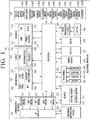
FIG. 1 is a block diagram of an electronic apparatus according to an embodiment of the disclosure; -
FIG. 2 is a block diagram of a device according to an embodiment of the disclosure; -
FIGS. 3A and3B illustrate an example system configuration according to various embodiments of the disclosure; -
FIG. 4 illustrates an example user interface (UI) screen in which an electronic apparatus accesses a user account of a server according to an embodiment of the disclosure; -
FIG. 5 illustrates an example UI screen in which an electronic apparatus is connected with an access point (AP) according to an embodiment of the disclosure; -
FIGS. 6A, 6B, and 6C illustrate an example UI which collectively performs a communication setting with respect to a plurality of household devices by using an electronic apparatus according to various embodiments of the disclosure; -
FIG. 7 illustrates an example of a process of collectively performing a communication setting with respect to a plurality of household devices through an electronic apparatus according to an embodiment of the disclosure; -
FIG. 8 illustrates another example of a process of collectively performing a communication setting with respect to a plurality of household devices through an electronic apparatus according to an embodiment of the disclosure; -
FIG. 9 illustrates an example in which an electronic apparatus performs a communication setting process again with respect to a plurality of household devices as an AP is replaced according to an embodiment of the disclosure; and -
FIG. 10 illustrates a flowchart of a method of collectively performing a communication setting with respect to a plurality of household devices through an electronic apparatus according to an embodiment of the disclosure. - Throughout the drawings, it should be noted that like reference numbers are used to depict the same or similar elements, features, and structures.
- The following description with reference to the accompanying drawings is provided to assist in a comprehensive understanding of various embodiments of the disclosure as defined by the claims. It includes various specific details to assist in that understanding but these are to be regarded as merely exemplary. Accordingly, those of ordinary skill in the art will recognize that various changes and modifications of the various embodiments described herein can be made without departing from the scope of the disclosure. In addition, descriptions of well-known functions and constructions may be omitted for clarity and conciseness.
- The terms and words used in the following description and claims are not limited to the bibliographical meanings, but, are merely used by the inventor to enable a clear and consistent understanding of the disclosure. Accordingly, it should be apparent to those skilled in the art that the following description of various embodiments of the disclosure is provided for illustration purpose only and not for the purpose of limiting the disclosure as defined by the appended claims.
- It is to be understood that the singular forms "a," "an," and "the" include plural referents unless the context clearly dictates otherwise. Thus, for example, reference to "a component surface" includes reference to one or more of such surfaces.
- In this disclosure, expressions such as "A or B" or "at least one of A and/or B" and the like may include all possible combinations of the items listed together. Expressions such as "first" or "second," and the like, may express their components irrespective of their order or importance and may be used to distinguish one component from another, but is not limited to these components. When it is mentioned that some (e.g., first) component is "(functionally or communicatively) connected" or "accessed" to another (second) component", the component may be directly connected to the other component or may be connected through another component (e.g., a third component).
- In this disclosure, "configured to (or set to)" as used herein may, for example, be used interchangeably with "suitable for", "having the ability to", "altered to", "adapted to", "capable of' or "designed to" in hardware or software. Under certain circumstances, the term "device configured to" may refer to "device capable of' doing something together with another device or components. For example, "a processor configured (or set) to perform A, B, and C" may refer to an exclusive processor (e.g., an embedded processor) for performing the corresponding operations, or a general-purpose processor (e.g., a central processing unit (CPU) or an application processor (AP)) capable of performing the corresponding operations by executing one or more software programs stored in a memory device.
- An electronic apparatus according to the various embodiments may include, for example, at least one of a smartphone, a tablet personal computer (PC), a desktop PC and a television (TV).
- A device according to the various embodiments may include at least one of, for example, a refrigerator, an air conditioner, a cleaner, an oven, a microwave, a washing machine and an air purifier.
- In the disclosure, the term "user" may refer to a person using an electronic device or a device using an electronic device (e.g., an artificial intelligence electronic device).
-
FIG. 1 is a block diagram of an electronic apparatus according to an embodiment of the disclosure. - The
electronic apparatus 201 may, for example, include at least one processor 210 (e.g. AP), acommunication interface 220, a subscriber identification module (SIM) 224, amemory 230, asensor module 240, aninput interface 250, adisplay 260, aninterface 270, anaudio module 280, acamera module 291, apower management module 295, abattery 296, anindicator 297, and amotor 298. Theprocessor 210 may, for example, control a number of hardware or software elements connected to theprocessor 210 by driving an operating system or application program, and perform various data processing and calculations. - The
controller 210 may control thecommunication interface 220 and thememory 230. - The
processor 210, for example, may be realized as a system on chip (SoC). According to an embodiment, theprocessor 210 may further include a graphics processing unit (GPU) and/or an image signal processor (ISP). Theprocessor 210 may include at least some among elements illustrated inFIG. 1 (e.g., cellular module 221). Theprocessor 210 may load and process commands or data received from at least one of the other components (e.g., non-volatile memory) into volatile memory and store the resulting data in non-volatile memory. - The
communication interface 220 may, for example, include acellular module 221, aWiFi module 223, a Bluetoothmodule 225, a global navigation satellite system (GNSS)module 227, a near field communication (NFC)module 228, and a radio frequency (RF)module 229. Thecellular module 221, for example, may provide a voice call, a video call, a text service, or internet service via a communication network. According to an embodiment, thecellular module 221 may perform a discrimination and an authentication for theelectronic apparatus 201 in a communication network by using a subscriber identification module (SIM) 224 (e.g., SIM card). According to an embodiment, thecellular module 221 may perform at least a part of the functions which can be provided by theprocessor 210. According to an embodiment, thecellular module 221 may include a communication processor (CP). According to an embodiment, at least some of (e.g., more than two) thecellular module 221,WiFi module 223, Bluetooth (BT)module 225,GNSS module 227 andNFC module 228 may be included in an integrated chip (IC) or an IC package. TheRF module 229, for example, may send and receive a communication signal (e.g., RF signal). TheRF module 229, for example, may include a transceiver, a power amp module (PAM), a frequency filer, a low noise amplifier (LNA), or an antenna and the like. According to an embodiment, at least one of thecellular module 221,WiFi module 223,Bluetooth module 225,GNSS module 227 andNFC module 228 may be send and receive the RF signal through a separate RF module. TheSIM 224 may, for example, include a card including a SIM or an embedded SIM, and may include an exclusive identification information (e.g., integrated circuit card identifier (ICCID) or subscriber information (e.g., international mobile subscriber identity (IMSI). - The memory 230 (e.g., memory 130) may, for example, include an
internal memory 232 or anexternal memory 234. Theinternal memory 232 may include at least one of, for example, a volatile memory (e.g., a dynamic random access memory (DRAM), a static RAM (SRAM), or a synchronous dynamic RAM (SDRAM)), a nonvolatile memory (e.g., an one time programmable read-only memory (OTPROM), a programmable ROM (PROM), an erasable programmable ROM (EPROM), an electrically erasable programmable ROM (EEPROM), a mask ROM, a flash ROM, a flash memory, a hard drive, and a solid state drive (SSD). Theexternal memory 234 may further include a flash drive, such as a compact flash (CF), a secure digital (SD), a micro secure digital (micro-SD), a mini secure digital (mini-SD), an extreme digital (xD), a multi-media card (MMC), or a memory stick. Theexternal memory 234 may be connected functionally or physically to theelectronic apparatus 201 through a variety of interfaces. - The
memory 230 may store an instruction to perform an operation of, when the processor is executed 210, storing identification information of an access point of an electronic apparatus, broadcasting identification information of the electronic apparatus via the communication interface, detecting, by the electronic apparatus, that a first device and a second device are connected to the electronic apparatus based on the identification information of the electronic apparatus, and substantially simultaneously transmitting the identification information of the access point to the first device and second device connected to the electronic apparatus. The identification information of the access point may include a service set identifier (SSID) of the access point. The identification information of the electronic apparatus may include an SSID of the electronic apparatus. - The
memory 230 may store an instruction that performs an operation of transmitting information relating to a first device and second device communicatively connected to the electronic apparatus to a server when theprocessor 210 is executed. Thesensor module 240 may, for example, measure a physical quantity or an operation state of theelectronic apparatus 201 and convert the measured or detected information to an electrical signal. Thesensor module 240 may include at least one of, for example, agesture sensor 240A, agyro sensor 240B, anatmospheric pressure sensor 240C, amagnetic sensor 240D, an acceleration sensor 240E, agrip sensor 240F, aproximity sensor 240G, a color sensor 240H (e.g., red, green, blue (RGB) sensor), a biosensor 240I, a temperature/humidity sensor 240J, anilluminance sensor 240K, and an ultra-violet (UV)sensor 240M. Additionally or alternatively, thesensor module 240, for example, may include an e-nose sensor, an electromyographic (EMG) sensor, an electroencephalogram (EEG) sensor, an electrocardiogram (ECG) sensor, an infrared (IR) sensor, an iris sensor and/or a fingerprint sensor. Thesensor module 240 may further include a control circuit to control at least one or more sensors therein. According to an embodiment, theelectronic apparatus 201 may further include a processor configured to control thesensor module 240 as part of theprocessor 210 or additionally, and control thesensor module 240 while theprocessor 210 is in a sleeping state. - The
input interface 250 may, for example, include atouch panel 252, adigital pen sensor 254, a key 256, or anultrasonic input apparatus 258. Thetouch panel 252 may, for example, use at least one of electrostatic type, pressure sensitive type, infrared type, and an ultraviolet type. Thetouch panel 252 may further include a control circuit. Thetouch panel 252 may further include a tactile layer to provide a tactile response to a user. The (digital)pen sensor 254, for example, may be part of a touch panel or include a separate detection sheet. The key 256, for example, may include a physical button, an optical key, or a keypad. Theultrasonic input device 258 may detect ultrasonic waves generated by an input tool, via a microphone (e.g., microphone 288), and may check the data corresponding to the detected ultrasonic waves. - The
display 260 may include thepanel 262, thehologram device 264, or theprojector 266 and/or a control circuit to control them. Thedisplay 260, for example, may include a liquid crystal display (LCD), a light-emitting diode (LED) display, an organic light-emitting diode (OLED) display, a microelectromechanical systems (MEMS) display, or an electronic paper display. Thedisplay 260, for example, may display a variety of contents (e.g., text, image, video, icon and/or symbol) to a user. Thedisplay 260 may include a touch screen, and may receive the inputs, for example, a touch, a gesture, a proximity indication or a hovering input using an electronic pen or a user's body part. - The
panel 262, for example, may be flexible, transparent or wearable. Thepanel 262 may be configured to include thetouch panel 252 and one or more modules. According to an embodiment, thepanel 262 may include a pressure sensor (or a force sensor) which may measure intensity of pressure with respect to a user touch. The pressure sensor may be realized to be integrated with thetouch panel 252 or as one or more sensors separated from thetouch panel 252. Thehologram device 264 can display a stereoscopic image in the air using interference of light. Theprojector 266 may project light onto a screen to display an image. The screen may, for example, be located within or outside theelectronic apparatus 201. Theinterface 270, for example, may include a high-definition multimedia interface (HDMI) 272, a universal serial bus (USB) 274, anoptical interface 276, or a D-subminiature 278. - Additionally or alternatively, the
interface 270, for example, may include a mobile high-definition link (MHL) interface, a secure digital (SD) card/multi-media card (MMC) interface, or Infrared data association (IrDA) standard interface. - The
audio module 280, for example, may convert sound and an electrical signal in bilateral directions. Theaudio module 280 may process sound information inputted or outputted through, for example, aspeaker 282, areceiver 284,earphones 286, amicrophone 288, or the like. Thecamera module 291, for example, may be an apparatus which is capable of photographing a still image and a video, and according to an embodiment, may include one or more image sensor (e.g., front surface sensor or rear surface sensor), a lens, an image signal processor (ISP), or a flash (e.g., LED, xenon lamp and the like). Thepower management module 295, for example, may manage the power of theelectronic apparatus 201. According to an embodiment, thepower management module 295 may include a power management integrated circuit (PMIC), a charger integrated circuit (IC), a battery 296 (e.g., a battery including a charge gauge), or a fuel gauge. The PMIC may use a wired and/or wireless charging method. A wireless charging method, for example, may include a magnetic resonance method, a self-induction method, or an electromagnetic wave method, and may further include an additional circuit for a wireless charging, for example, a coil loop, a resonant circuit, or a rectifier, etc. The battery gauge may, for example, measure remaining amount of thebattery 296, a voltage during charging, the current, or the temperature. Thebattery 296, for example, may include a rechargeable battery and/or a solar battery. - The
indicator 297 may display a particular state, for example, a booting state, a messaging state, a charging state, or etc., of theelectronic apparatus 201 or of part of the electronic apparatus 201 (e.g. processor 210). Themotor 298 may convert an electrical signal into a mechanical vibration, and generate vibration, haptic effect, or the like. Theelectronic apparatus 201 may, for example, include a mobile TV support device (e.g., a GPU) for processing media data according to standards such as digital multimedia broadcasting (DMB), digital video broadcasting (DVB), mediaFloTM, etc. Each element described in the present specification may consist of one or more than one components, and the name of the components may vary depending on the type of electronic apparatuses. According to various embodiments, theelectronic apparatus 201 may omit some constituent elements, may further include other additional constituent elements, or may be combined to form a single entity which performs the same functions as those elements before being combined. -
FIG. 2 is a block diagram of a device according to an embodiment of the disclosure. - Referring to
FIG. 2 , adevice 412 may include a processor 4121 (e.g., at least one processor), acommunication interface 4123, amemory 4125, aninput interface 4127 and anoutput interface 4129. - The
processor 4121 may control the overall operations of thedevice 412. For example, theprocessor 4121 may control thecommunication interface 4123 and thememory 4125. The detailed description of theprocessor 4121 is the same as described above with reference toFIG. 1 and, therefore, further description will not be provided. - The
communication interface 4123 may include a nearfield communication module (e.g., WiFi), and may communicate with an AP and an electronic apparatus via the nearfield communication module. - The
memory 4125 may store AP identification information received via thecommunication interface 4123 and identification information of the electronic apparatus. Thememory 4125 may store an instruction which, when theprocessor 4121 is executed, performs an operation of connecting with the electronic apparatus via the communication interface using a first data stored in thememory 4125, an operation of receiving identification information of an access point from the electronic apparatus, an operation of connecting with the access point using the identification information of the access point received from the electronic apparatus, an operation of connecting with a server via the access point, an operation of receiving second identification information of the electronic apparatus from the server and storing the received second identification information in the memory, and an operation of, when disconnected from the access point, connecting with the electronic apparatus using the second identification information. The first data may be stored in thememory 4125 of the device at the time of the manufacturing of the device. The first data may include identification information of the electronic apparatus. For example, the first data may include an SSID of the electronic apparatus. - The
input interface 4127 may, for example, be a physical button, and the user may input a command to operate the device via the input interface. For example, the user may control the device to be operated in a communication setting mode via the input interface. - The
output interface 4129 may provide information relating to an operation state of a device to a user through a visual, auditory, and/or tactile feedback. -
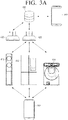
FIGS. 3A and3B illustrate an example system configuration according to various embodiments of the disclosure. - Referring to
FIG. 3A , a system may include anelectronic apparatus 201, a secondelectronic apparatus 202, afirst device 410, asecond device 412, athird device 414, access points (AP) 420 and 422, and aserver 430. - The
electronic apparatus 201 may be an external electronic apparatus. - The
electronic apparatus 201 may support communication setting of thefirst device 410, thesecond device 412, and thethird device 414. For example, theelectronic apparatus 201 may store identification information of the access point in a memory of theelectronic apparatus 201, and broadcast identification information of theelectronic apparatus 201. In addition, thefirst device 410 and thesecond device 412 may communicatively connect with theelectronic apparatus 201 based on the identification information of theelectronic apparatus 201. Theelectronic apparatus 201 may substantially simultaneously transmit the identification information of the access point to thefirst device 410 and thesecond device 412. Thefirst device 410 and thesecond device 412 may communicatively connect with the access point using the identification information of the access point. - The
first device 410 and thesecond device 412 may access the server via the access point, and the server may transmit second identification information of theelectronic apparatus 201 to thefirst device 410, thesecond device 412, and theelectronic apparatus 201. Thefirst device 410 and thesecond device 412 may, when disconnected from the server, communicatively connect with theelectronic apparatus 201 using the second identification information. - The
electronic apparatus 201 may, for example, be a smartphone of a user, and may be connected to theAPs server 430 via the communication interface. When theelectronic apparatus 201 is connected with theAPs electronic apparatus 201 may be connected with theserver 430 via theAPs - The user may input identification information (e.g., an SSID) of an AP to be connected and a password to the
electronic apparatus 201, and theelectronic apparatus 201 may store the identification information of the AP and password inputted by the user in a memory. - For example, the user may input "KHOME" as an SSID and "1234" as a password to connect with the
AP 420, and theelectronic apparatus 201 may store the input "KHOME" and the input "1234" in the memory. - The
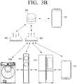
first device 410, thesecond device 412, and thethird device 414 may include a nearfield communication module such as WiFi. Thefirst device 410, thesecond device 412, and thethird device 414 may be connected to theaccess point 420, and may be connected with theserver 430 via theAP 420. - The
first device 410, thesecond device 412, and thethird device 414 may be home appliances within households, and may, for example, be a micro wave oven (MWO), a refrigerator, a washing machine or an air conditioner. Thefirst device 410, thesecond device 412, and thethird device 414 may be connected with an electronic apparatus using a predetermined first data. The first data may, for example, include identification information (e.g., an SSID) of an electronic apparatus that is broadcasted while theelectronic apparatus 201 is operated in an AP mode. In addition, the first data may include names of thefirst device 410, thesecond device 412 and thethird device 414. The first data may be assigned by the manufacturer at the time of manufacturing the device and may be stored in a memory. In addition, if devices have the same manufacturer, the same first data may be assigned. For example, when thefirst device 410, thesecond device 412 and thethird device 414 were manufactured by one manufacturer, first data of thefirst device 410, thesecond device 412 and thethird device 414 may be the same. - Meanwhile, the
first device 410, thesecond device 412 and thethird device 414 may not include a display apparatus for displaying information. Accordingly, it may be difficult for the user to directly manipulate thefirst device 410, thesecond device 412 and thethird device 414 to connect the devices with theAP 420. - To connect the
first device 410, thesecond device 412, and thethird device 414 with theAP 420, it is necessary that the device identifies identification information (e.g., an SSID) of theAP 420. In a case in which thefirst device 410, thesecond device 412 and thethird device 414 are communicatively connected with theelectronic apparatus 201, thefirst device 410, thesecond device 412, and thethird device 414 may receive identification information of theAP 420 from theelectronic apparatus 201. - In a case in which the user operates the
electronic apparatus 201 in an AP mode, theelectronic apparatus 201 may broadcast identification information of the electronic apparatus with a predetermined value for a predetermined time. In this case, the identification information of the electronic apparatus may be identical to the first data of the device stored in the device. Thus, in a case in which the electronic apparatus is operated in a soft AP mode and thefirst device 410, thesecond device 412, and thethird device 414 are operated in a communication setting mode, thefirst device 410, thesecond device 412, and thethird device 414 may be communicatively connected with theelectronic apparatus 201 using the first data. - According to an embodiment, to operate the
electronic apparatus 201 in an AP mode, the user may execute a communication setting application (e.g., app) in the electronic apparatus. The communication setting application may be provided by the device manufacturer or may be provided by a third party. - When the user executes a communication setting application in the
electronic apparatus 201 is operated in the AP mode and the same identification information as the first data stored in thefirst device 410, thesecond device 412, and thethird device 414 is broadcasted. According to an embodiment, a user account may be generated in theserver 430 before the communication setting application is executed. In addition, theelectronic apparatus 201 may store identification information of the communicatively-connectedAP 420 in a memory. - The
first device 410, thesecond device 412, and thethird device 414 may receive identification information of theelectronic apparatus 201 which is broadcasted by theelectronic apparatus 201, and may send a connection request to theelectronic apparatus 201 using the first data stored in the memory of thefirst device 410, thesecond device 412, and thethird device 414. When theelectronic apparatus 201 approves connection, theelectronic apparatus 201 may be communicatively connected with thefirst device 410, thesecond device 412, and thethird device 414. According to an embodiment, information (e.g., 'air conditioner', 'refrigerator', etc.) relating to a device connected to theelectronic apparatus 201 may be displayed on a display. - In a state in which the
first device 410, thesecond device 412, and thethird device 414 are connected with theelectronic apparatus 201, theelectronic apparatus 201 may substantially simultaneously transmit the identification information of theAP 420 to the connectedfirst device 410, the connectedsecond device 412 and the connectedthird device 414 based on a user input. Herein, the term "collectively" may be interpreted to refer to "simultaneously" or "substantially simultaneously". - When the
first device 410, thesecond device 412, and thethird device 414 receive the identification information of theAP 420 from theelectronic apparatus 201, thefirst device 410, thesecond device 412, and thethird device 414 may be connected with theAP 420 using the identification information of theAP 420. - The
AP 420 may be connected with theserver 430. In a case in which thefirst device 410, thesecond device 412, and thethird device 414 are connected with theAP 420, thefirst device 410, thesecond device 412, and thethird device 414 may be connected with theserver 430 via theAP 420. - The
server 430 may be a server that manages a household device (e.g., home appliances and internet of things (IoT)). Theserver 430 may store identification information (e.g., Mac address, IP address, model name of the device, etc.) of thefirst device 410,second device 412 andthird device 414 connected with theAP 420 and register thefirst device 410, thesecond device 412, and thethird device 414. - Meanwhile, the
server 430 may generate a user account and manage a plurality of devices within a household. So as to register a device in a user account, account information is required. The account information may include an ID and a password, and theelectronic apparatus 201 may transmit the account information to thefirst device 410, thesecond device 412, and thethird device 414. - The
server 430 may, when connected with thefirst device 410, thesecond device 412, and thethird device 414, register thefirst device 410, thesecond device 412, and thethird device 414 in a user account of theserver 430 through the account information. The server may transmit, to theelectronic apparatus 201, information indicating that thefirst device 410, thesecond device 412, and thethird device 414 are connected. - When the
first device 410, thesecond device 412, and thethird device 414 are registered with theserver 430, the user may control thefirst device 410, thesecond device 412, and thethird device 414 through theelectronic apparatus 201. For example, when the first device 410 (e.g., an air conditioner 410) is connected with theserver 430, theserver 430 may manage the temperature and operation time of the air conditioner. For example, the server may generate a user account and manage a plurality of devices within a household. The user may access a user account of theserver 430 through theelectronic apparatus 201 and control theair conditioner 410 registered with the user account. - An account of the second
electronic apparatus 202 may be interlocked with the user or may be shared with the user. The secondelectronic apparatus 202 may, for example, be an electronic apparatus of a family member. - When the second
electronic apparatus 202 shares a user account of theelectronic apparatus 201 or is interlocked with the user account, the secondelectronic apparatus 202 may control thefirst device 410, thesecond device 412, and thethird device 414 without an additional device registration process. - In addition, the second
electronic apparatus 202 may copy device information stored in the user account onto an account of the user of theelectronic apparatus 202. - Meanwhile, in a case in which a third device, which is not present in the user account (hereinafter referred to as "first user account") using the first
electronic apparatus 201, is registered with the user account (hereinafter referred to as "second user account") using the secondelectronic apparatus 202, the firstelectronic apparatus 201 may update the account information by adding registration information relating to the third device to the first user account through account linkage. - Meanwhile, when the
AP 420 connected with theserver 430 is replaced with theAP 422, thefirst device 410, thesecond device 412, and thethird device 414 may be disconnected from theserver 430. - When disconnected from the
server 430, thefirst device 410, thesecond device 412, and thethird device 414 may be connected with theelectronic apparatus 201 by using a predetermined first data. - The
electronic apparatus 201 may store identification information of thenew AP 422 in a memory, when thefirst device 410, thesecond device 412, and thethird device 414 and theelectronic apparatus 201 are connected again, transmit the identification information of thenew AP 422 to thefirst device 410, thesecond device 412, and thethird device 414. Thefirst device 410, thesecond device 412, and thethird device 414 may be connected to theAP 422 by using the identification information of theAP 422 and may be connected with theserver 430 again. - According to an embodiment, when the
first device 410, thesecond device 412, and thethird device 414 are registered with theserver 430, theserver 430 may transmit new identification information to the connectedfirst device 410, the connectedsecond device 412, the connectedthird device 414, and theelectronic apparatus 201. The new identification information transmitted to thedevices server 430, an SSID may be "SamsungHome_01" and a password may be "5678". - The
first device 410, thesecond device 412, thethird device 414, and theelectronic apparatus 201 may store new identification information (hereinafter referred to as "second identification information" assigned by the server in a memory. When thefirst device 410, thesecond device 412, and thethird device 414 are disconnected from theserver 430 and a communication setting operation is performed again, thefirst device 410, thesecond device 412, thethird device 414, and theelectronic apparatus 201 may communicatively connect with theelectronic apparatus 201 by using the second identification information. As theelectronic apparatus 201, thefirst device 410, thesecond device 412, and thethird device 414 perform a communication setting operation as described above, the error that another device is erroneously registered with a user account because the same identification information is used by another user. - Meanwhile, the
first device 410, thesecond device 412, and thethird device 414 may be connected with theelectronic apparatus 201 by using the first data initially assigned at the time of the manufacturing of the device based on the user input. For example, in a case in which the user presses a particular button (e.g., an "easy setup" button) included in thedevices first device 410, thesecond device 412, and thethird device 414 may attempt to connect with theelectronic apparatus 201 by using the initially-assigned first data. The first data may include identification information of theelectronic apparatus 201. In addition, theelectronic apparatus 201 may initially-assigned identification information according to a user input. - Meanwhile, in a case in which some of household devices are far-distanced from the
electronic apparatus 201 and cannot be connected with theelectronic apparatus 201, AP identification information may be received using a mesh communication between devices. -
FIG. 3B illustrates anelectronic apparatus 201, a secondelectronic apparatus 202, afirst device 410, asecond device 412, athird device 414, access points (AP) 420 and 422, and aserver 430. - For example, the
second device 412 and theelectronic apparatus 201 may be directly connected via communication. Thedevices electronic apparatus 201 and thus cannot be directly connected via communication. In this case, thesecond device 412 receives identification information of theAP 420 from theelectronic apparatus 201, and thefirst device 410 transmits the identification information of theAP 420 back to thethird device 414. - The
devices AP 420, and be connected to theAP 420 using the identification information of theAP 420. -
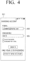
FIG. 4 illustrates an example user interface (UI) screen in which an electronic apparatus accesses a user account of a server according to an embodiment of the disclosure. -
FIGS. 3A and4 illustrate anaccount ID 503 andpassword 505 which are input by the user on thescreen 501 of theelectronic apparatus 201. - When the
electronic apparatus 201 executes a communication setting app, theserver 430 may display a UI requesting an account information input on thescreen 501. For example, a UI requesting input of theaccount ID 503 and the password may be displayed on thescreen 501. - When the user inputs the
account ID 503 and thepassword 505, the user may access a user account of theserver 430. Theaccount ID 503 may, for example, be an email address of the user. - When the user inputs the
account ID 503 and thepassword 505 and an authentication is complete, the user may control a device registered with the user account through theelectronic apparatus 201. -
FIG. 5 illustrates an example UI screen in which an electronic apparatus is connected with an AP according to an embodiment of the disclosure. - Referring to
FIG. 5 , an AP identificationinformation input button 513 andAP identification information screen 511. - The AP identification information may, for example, include an
SSID 515 and/orpassword 517 of the AP. - When the user attempts to connect with the AP, a UI requesting input of the
SSID 515 andpassword 517 of the AP may be displayed on thescreen 511. When the user inputs theSSID 515 and thepassword 517, the AP authenticates an electronic apparatus based on the inputtedSSID 515 and the inputted password, and the electronic apparatus may be connected with the server via the AP. - The inputted
SSID 515 andpassword 517 of the AP may be stored in a memory of the electronic apparatus. When the device is communicatively connected with the electronic apparatus, an SSID and password of an AP stored in the memory may be transmitted to a device connected with the electronic apparatus. In a case in which a plurality of devices is connected with the electronic apparatus, the electronic apparatus may substantially simultaneously transmit the SSID and password of the AP to the plurality of devices. - According to an embodiment, it is possible to display a list of connectible APs on the screen without the need for the user to directly input the SSID, and the user may input the SSID by selecting one of the APs in the list and store the selected one in a memory.
-
FIGS. 6A, 6B, and 6C illustrate an example UI which collectively performs a communication setting with respect to a plurality of household devices by using an electronic apparatus according to various embodiments of the disclosure. - Referring to
FIG. 6A , when the user executes a communication setting app, the electronic apparatus may access an account of a server and abutton 523 may be displayed on thescreen 521. When the user selects thebutton 523, a list ofdevices - Referring to
FIG. 6B , in a state in which a list of currently-connected devices is displayed on thescreen 531, when the user selects thebutton 533, the electronic apparatus may transmit AP identification information to a device displayed on the list. - Referring to
FIG. 6C , a device may be connected with the AP by using the AP identification information received from the electronic apparatus. The server may register the connected device with a user account, and when the registration is complete,display messages screen 541. -
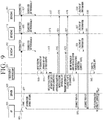
FIG. 7 illustrates an example of a process of collectively performing a communication setting with respect to a plurality of household devices through an electronic apparatus according to an embodiment of the disclosure. -
FIG. 7 illustrates anAP 420, aserver 430, anelectronic apparatus # 1 201, a device #1412, adevice # 2 410, adevice # 3 414, and anelectronic apparatus # 2 202. - The
device # 1 412 is a first device. Thedevice # 2 410 is a second device. Thedevice # 3 414 is a third device. Theelectronic apparatus # 1 201 is an external electronic apparatus. - For convenience of explanation, it will be assumed that an SSID of the
AP 420 for connecting with theAP 420 is "KHome" and that a password is "1234". It will be assumed that the first data assigned by the manufacturer at the time of the manufacturing of thedevices electronic apparatus # 1 201 is operated in an AP mode, the SSID of theelectronic apparatus # 1 201 is "SamsungHome", and that the password is "1234". - At
operation 701, when the user executes a communication setting application in the electronic apparatus and inputs a collective device addition command, atoperation 702, the electronic apparatus inputs an SSID and password of theAP 420 to be connected. For example, the user inputs "KHome" as the SSID and "1234" as the password, and theelectronic apparatus # 1 201 stores the input "KHome" and the input password "1234" in a memory. - The
electronic apparatus 201 is operated for a predetermined time with the SSID "SamsungHome" and the password "1234", atoperation 703. For example, theelectronic apparatus # 1 201 broadcasts "SamsungHome". - The
device # 1 412 makes a connection attempt to theelectronic apparatus # 1 201 using the SSID and password (e.g., "SamsungHome" and "1234") assigned at the time of manufacturing while thedevice # 1 412 is operated in a connection start mode, atoperation 704. Thedevice # 1 412 sends an approval request for connection to theelectronic apparatus # 1 201, atoperation 707. Atoperation 710, theelectronic apparatus # 1 201 approves the device #1412 and the device #1412 is connected with theelectronic apparatus # 1 201. - The
device # 2 410 makes a connection attempt to theelectronic apparatus # 1 201 using the SSID and password (e.g., "SamsungHome" and "1234") assigned at the time of manufacturing while thedevice # 1 412 is operated in a connection start mode, atoperation 705. Thedevice # 2 410 sends an approval request for connection to theelectronic apparatus # 1 201, atoperation 708. Atoperation 711, theelectronic apparatus # 1 201 approves thedevice # 2 410 and thedevice # 2 410 is connected with theelectronic apparatus # 1 201. - The
device # 3 414 makes a connection attempt to theelectronic apparatus # 1 201 using the SSID and password (e.g., "SamsungHome" and "1234") assigned at the time of manufacturing while thedevice # 1 412 is operated in a connection start mode, atoperation 706. Thedevice # 3 414 sends an approval request for connection to theelectronic apparatus # 1 201, atoperation 709. Atoperation 712, theelectronic apparatus # 1 201 approves thedevice # 3 414 and thedevice # 3 414 is connected with theelectronic apparatus # 1 201. - The
electronic apparatus # 1 201, after being connected with the device #1412, thedevice # 2 410, and thedevice # 3 414, substantially simultaneously transmits identification information of theAP 420 to thedevice # 1 412, thedevice # 2 410, and thedevice # 3 414. - That is, at
operations electronic apparatus # 1 201 may substantially simultaneously transmit identification (e.g., "KHome" as an SSID and "1234" as a password) of theAP 420 to be connected to thedevice # 1 412, thedevice # 2 410, and thedevice # 3 414. - The electronic apparatus identifies the number of the
device # 1 412, thedevice # 2 410 and thedevice # 3 414 installed within household and then converts an operation to a station mode atoperation 716, connects with theAP 420 atoperation 717, sends an authentication request using an account ID and a password to theserver 430 to access the user account of theserver 430 via theAP 420 and accesses the user account atoperation 718. Meanwhile, the electronic apparatus may register information relating to household devices connected to itself in the user account while the electronic apparatus accesses the user account. - The
device # 1 412 may be connected with theAP 420 using the received SSID and password of theAP 420, atoperations server 430 via theAP 420 and sends an authentication request of the device #1412, atoperation 725. - The
device # 2 410 may be connected with theAP 420 using the received SSID and password of theAP 420, atoperations server 430 via theAP 420 and sends an authentication request of thedevice # 2 410, atoperation 726. - The
device # 3 414 may be connected with theAP 420 using the received SSID and password of theAP 420, atoperations server 430 via theAP 420 and sends an authentication request of thedevice # 3 414, atoperation 727. - The
server 430 completes authentication of theelectronic apparatus # 1 201, atoperation 728. - The
server 430 completes authentication of thedevice # 1 412 and registers the device #1412 in the user account, atoperation 729. - The
server 430 completes authentication of thedevice # 2 410 and registers thedevice # 2 410 in the user account, atoperation 730. - The
server 430 completes authentication of thedevice # 3 414 and registers thedevice # 3 414 in the user account, atoperation 731. - The
electronic apparatus # 1 201 may complete the preparation for controlling thedevices server 430 and wait for a user command, atoperation 732. - Meanwhile, the second
electronic apparatus 202 may be connected with theserver 430 and requests theserver 430 to connect with the user account, atoperation 741. Theserver 430 may request theelectronic apparatus # 1 201 to check account connection with respect to theelectronic apparatus # 2 202, atoperation 742. When theelectronic apparatus # 1 201 approves the account connection with respect to theelectronic apparatus # 2 202, atoperation 743, theserver 430 may proceed with the information interlock update of thedevice # 1 412, thedevice # 2 410 and thedevice # 3 414 with respect to theelectronic apparatus # 2 202, atoperation 744. -
FIG. 8 illustrates another example of a process of collectively performing a communication setting with respect to a plurality of household devices by using a mesh technology in an electronic apparatus according to an embodiment of the disclosure. -
FIG. 8 illustrates anAP 420, aserver 430, anelectronic apparatus # 1 201, a device #1412, adevice # 2 410, adevice # 3 414, and anelectronic apparatus # 2 202. - The
device # 1 412 is a first device. Thedevice # 2 410 is a second device. Thedevice # 3 414 is a third device. Theelectronic apparatus # 1 201 is an external electronic apparatus. - The
device # 1 412, thedevice # 2 410 and thedevice # 3 414 may transmit or receive data using the mesh technology. Mesh technology is a technology that expands the coverage by communication between each device in case the home is wide and some devices cannot connect to the home router. - For example, the
device # 1 412 and thedevice # 2 410 are communicatively connected with each other, and thedevice # 1 412 and thedevice # 2 410 may transmit or receive data to/from each other. Thedevice # 2 410 and thedevice # 3 414 are communicatively connected with each other, and thedevice # 2 410 and thedevice # 3 414 may transmit or receive data to/from each other. - For convenience of explanation, it will be assumed that the
electronic apparatus # 1 201 and thedevice # 1 412 may communicate with each other, but that thedevice # 2 410 and thedevice # 3 414 are distanced far away and cannot directly communicate with each other. In addition, it will be assumed that the device #1412 and thedevice # 2 410 may communicate with theAP 420, but that thedevice # 3 414 is distanced far away from theAP 420 and cannot directly communicate with theAP 420. - For convenience of explanation, it will be assumed that an SSID of the
AP 420 for connecting with theAP 420 is "KHome" and that a password is "1234". It will be assumed that the first data assigned by the manufacturer at the time of the manufacturing of thedevices electronic apparatus # 1 201 is operated in an AP mode, the SSID of theelectronic apparatus # 1 201 is "SamsungHome", and that the password is "1234". - At
operation 801, when the user executes a communication setting application in the electronic apparatus and inputs a collective device addition command, atoperation 803, the electronic apparatus inputs an SSID and password of theAP 420 to be connected. For example, the user inputs "KHome" as the SSID and "1234" as the password, and theelectronic apparatus # 1 201 stores the input "KHome" and the input password "1234" in a memory. - The
electronic apparatus 201 is operated for a predetermined time with the SSID "SamsungHome" and the password "1234", atoperation 805. For example, theelectronic apparatus # 1 201 broadcasts "SamsungHome". - The
device # 1 412 makes a connection attempt to theelectronic apparatus # 1 201 using the SSID and password (e.g., "SamsungHome" and "1234") assigned at the time of manufacturing while thedevice # 1 412 is operated in a connection start mode, atoperation 807. - The
device # 2 410 makes a connection attempt to theelectronic apparatus # 1 201 using the SSID and password (e.g., "SamsungHome" and "1234") assigned at the time of manufacturing while thedevice # 1 412 is operated in a connection start mode, atoperation 809. - The
device # 3 414 makes a connection attempt to theelectronic apparatus # 1 201 using the SSID and password (e.g., "SamsungHome" and "1234") assigned at the time of manufacturing while thedevice # 1 412 is operated in a connection start mode, atoperation 811. - The
device # 1 412 sends an approval request for connection to theelectronic apparatus # 1 201, atoperation 815. Atoperation 813, theelectronic apparatus # 1 201 approves thedevice # 1 412 and thedevice # 1 412 is connected with the electronic apparatus #1201. When the device #1402 is communicatively connected with the electronic apparatus #1201, the electronic apparatus #1201 transmits an SSID and password of theAP 420 to thedevice # 1 412, atoperation 821. - Meanwhile, the
device # 2 410 is at a far distance from theelectronic apparatus # 1 201 and is in a state where it is difficult to directly receive data from theelectronic apparatus # 1 201, atoperation 809, and receives an SSID and password of theelectronic apparatus # 1 201 through thedevice # 1 412, atoperation 817. - The
device # 3 414 is at a far distance from theelectronic apparatus # 1 201 and is in a state where it is difficult to directly receive data from theelectronic apparatus # 1 201, atoperation 819, and receives an SSID and password of theelectronic apparatus # 1 201 through thedevice # 1 412 and thedevice # 2 410, atoperation 819. - The
device # 2 410 may receive data (e.g., an SSID and password of the AP 420) for connecting with theAP 420 from thedevice # 1 412 by using a mesh technology, atoperation 823. - Likewise, the
device # 3 414 may also receive data for connecting with theAP 420 from thedevice # 2 410 by using the mesh technology, atoperation 825. - The
electronic apparatus # 1 201 identifies the number of thedevice # 1 412, thedevice # 2 410 and thedevice # 3 414 installed within household and then converts an operation to a station mode atoperation 827, connects with theAP 420 atoperation 829, sends an authentication request using an account ID and a password to theserver 430 to access the user account of theserver 430 via theAP 420 and accesses the user account at operation 831. - Meanwhile, the electronic apparatus may register information relating to household devices connected to itself in the user account while the electronic apparatus accesses the user account.
- The
device # 1 412 may be connected with theAP 420 using the SSID and password of theAP 420 received from the electronic apparatus, atoperations server 430 via theAP 420 and sends an authentication request of thedevice # 1 412, atoperation 845. - The
device # 2 410 may be connected with theAP 420 using the SSID and password of theAP 420, atoperations server 430 via theAP 420 and sends an authentication request of thedevice # 2 410, atoperation 847. - Meanwhile, the
device # 3 414 may be connected with theAP 420 using the SSID and password of theAP 420, atoperation 837. In a case in which it is at a far distance and it is difficult to be directly connected with theAP 420, thedevice # 3 414 is connected with thedevice # 2 410 adjacent to theAP 420 and sharing the information, connects with theserver 430 through thedevice # 2 410, sends an authentication request of thedevice # 3 414, atoperation 849. Atoperation 843, thedevice # 3 414, when located at far distance from the home router, connects with a nearby home appliance (e.g.,device # 2 410) with which information is initially shared (same key). - The
server 430 completes account authentication of theelectronic apparatus # 1 201, atoperation 851. - The
server 430 completes authentication of thedevice # 1 412 and registers thedevice # 1 412 in the user account, atoperation 853. - The
server 430 completes authentication of thedevice # 2 410 and registers thedevice # 2 410 in the user account, atoperation 855. - The
server 430 completes authentication of thedevice # 3 414 and registers thedevice # 3 414 in the user account, atoperation 857. - The
electronic apparatus # 1 201 may complete the preparation for controlling thedevices server 430 and wait for a user command, atoperation 859. - Meanwhile, the
electronic apparatus # 2 202 may be connected with theserver 430 and requests theserver 430 to connect with the user account, atoperation 871. Theserver 430 may request theelectronic apparatus # 1 201 to check account connection with respect to theelectronic apparatus # 2 202, atoperation 873. When theelectronic apparatus # 1 201 approves the account connection with respect to theelectronic apparatus # 2 202, atoperation 875, theserver 430 may proceed with the information interlock update of thedevice # 1 412, thedevice # 2 410 and thedevice # 3 414 with respect to theelectronic apparatus # 2 202, atoperation 877. -
FIG. 9 illustrates an example in which an electronic apparatus performs a communication setting process again with respect to a plurality of household devices as an AP is replaced according to an embodiment of the disclosure. -
FIG. 9 illustrates anAP 420, anAP 422, anelectronic apparatus 201, adevice # 1 412, adevice # 2 410, adevice # 3 414. Thedevice # 1 412 is a first device. Thedevice # 2 410 is a second device. Thedevice # 3 414 is a third device. Theelectronic apparatus # 1 201 is an external electronic apparatus. - For convenience of explanation, it will be assumed that an SSID of the
AP 420 for connecting with theAP 420 is "KHome" and that a password is "1234". - It will be assumed that an SSID of the
AP 422 for connecting with theAP 422 is "KHome2" and that a password is "2345". - It will be assumed that the first data assigned by the manufacturer at the time of the manufacturing of the
devices electronic apparatus # 1 201 is operated in an AP mode, the SSID of theelectronic apparatus # 1 201 is "SamsungHome", and that the password is "1234". - It will be assumed that initially, the device #1412, the
device # 2 410, and thedevice # 3 414 are connected with theAP 420, but that theAP 420 is replaced with theAP 422 and thus that thedevice # 1 412, thedevice # 2 410, and thedevice # 3 414 are disconnected with theAP 420. - At
operation 901, as theAP 420 is replaced with theAP 422, identification of an AP is changed. - As the
device # 1 412 is disconnected from theAP 420, thedevice # 1 412 periodically searches for an AP, atoperation 903. - As the
device # 2 410 is disconnected from theAP 420, thedevice # 1 412 periodically searches for an AP, atoperation 905. - As the
device # 3 414 is disconnected from theAP 420, thedevice # 1 412 periodically searches for an AP, atoperation 907. - The
electronic apparatus # 1 201 receives an SSID and password of theAP 422 to be newly connected, atoperation 909. For example, the user inputs "KHome2" as the SSID and "2345" as the password, and theelectronic apparatus # 1 201 stores the input "KHome2" and the input password "2345" in a memory. - The
electronic apparatus 201 is operated for a predetermined time with the SSID "SamsungHome" and the password "1234", atoperation 911. For example, theelectronic apparatus # 1 201 broadcasts "SamsungHome". - The device #1412 sends an authentication request for connection to the
electronic apparatus # 1 201 using the SSID and password (e.g., "SamsungHome" and "1234") assigned at the time of manufacturing, atoperation 913. Atoperation 919, theelectronic apparatus # 1 201 approves thedevice # 1 412 and thedevice # 1 412 is connected with theelectronic apparatus # 1 201. - The
device # 2 410 sends an authentication request for connection to theelectronic apparatus # 1 201 using the SSID and password (e.g., "SamsungHome" and "1234") assigned at the time of manufacturing, atoperation 915. Atoperation 921, theelectronic apparatus # 1 201 approves thedevice # 2 410 and thedevice # 2 410 is connected with theelectronic apparatus # 1 201. - The
device # 3 414 makes a connection attempt to theelectronic apparatus # 1 201 using the SSID and password (e.g., "SamsungHome" and "1234") assigned at the time of manufacturing while thedevice # 1 412 is operated in a connection start mode, atoperation 917. Atoperation 923, theelectronic apparatus # 1 201 approves thedevice # 3 414 and thedevice # 3 414 is connected with theelectronic apparatus # 1 201. - The
electronic apparatus # 1 201, after being connected with thedevice # 1 412, thedevice # 2 410, and thedevice # 3 414, substantially simultaneously transmits identification information of theAP 422 to thedevice # 1 412, thedevice # 2 410, and thedevice # 3 414. - That is, at
operations electronic apparatus # 1 201 may substantially simultaneously transmit identification (e.g., "KHome2" as an SSID and "1234" as a password) of theAPA 422 to be connected to thedevice # 1 412, thedevice # 2 410, and thedevice # 3 414. - The electronic apparatus identifies the number of
device # 1 412,device # 2 410 anddevice # 3 414 installed within household atoperation 931, then convert an operation mode to a station mode, and is connected with theAP 422, atoperation 933. - The
device # 1 412 is connected with theAP 422 by using an SSID and password of theAP 422, atoperations - The
device # 2 410 is connected with theAP 422 by using an SSID and password of theAP 422, atoperations - The
device # 3 414 is connected with theAP 420 by using an SSID and password of theAP 422 as well, atoperation 939. - The
electronic apparatus # 1 201 may complete the preparation for controlling thedevices server 430 and wait for a user command, atoperation 945. - The
server 430 completes authentication of thedevice # 1 412, thedevice # 2 410 and thedevice # 3 414, registers the device #1412, thedevice # 2 410 and thedevice # 3 414 in the user account, and at operation 947, update information relating to theconnected AP 422. -
FIG. 10 illustrates a flowchart of a method of collectively performing a communication setting with respect to a plurality of household devices through an electronic apparatus according to an embodiment of the disclosure. - Referring to
FIG. 10 , the electronic apparatus stores identification information of the access point in a memory, atoperation 1001. The identification information of the access point may, for example, include a service set identifier (SSID) of the access point. The user may input an SSID and/or password of the access point to connect with the access point, and the electronic apparatus may store the input SSID and/or the input password in the memory. - The electronic apparatus broadcasts predetermined identification information of the electronic apparatus via a communication interface,
operation 1003. The identification information of the electronic apparatus is to identify the electronic apparatus when the electronic apparatus is operated in an AP mode, and may, for example, include an SSID. That is, the electronic apparatus broadcasts its own SSID via a communication interface. When the user executes a communication setting application in the electronic apparatus, predetermined identification information (e.g., an SSID) provided by the manufacturer of the device (e.g., a factory setting) may be broadcasted. In addition, the SSID of the electronic apparatus may be identical to the first data stored in the device. The device located near the electronic apparatus receives an SSID broadcasted by the electronic apparatus and identifies the electronic apparatus, communicatively connects with the electronic apparatus by using the first data stored in the memory, and requests authentication of the connection via communication. For example, since the SSID broadcasted by the electronic apparatus is identical to the first data stored in the device, the device may transmit its own identification information (e.g., product name or model name) to the electronic apparatus and request authentication. In this process, the electronic apparatus may request a device for a password, and the device may transmit a password included in the first data to the electronic apparatus. In addition, the electronic apparatus may receive the password and approves communicative connection of the device. Once the approval is complete, the device may be communicatively connected with the electronic apparatus. - The electronic apparatus may detect that one or more device is connected with the electronic apparatus by using the identification information of the electronic apparatus, at
operation 1005. For example, the electronic apparatus may detect that the first device and the second device are communicatively connected with the electronic apparatus based on the identification information of the electronic apparatus. The electronic apparatus may detect a device communicatively connected to the electronic apparatus and identify the number of communicatively connected devices. - The electronic apparatus substantially simultaneously transmits AP identification information to one or more device connected with the electronic apparatus, at operation 1007. For example, in a case in which the electronic apparatus is communicatively connected with the first device and the second device, the electronic apparatus may substantially simultaneously transmit identification information (e.g., an SSID) of the access point to the first device and the second device. According to an embodiment, the electronic apparatus may transmit a password to connect with the AP to the device together with the identification information. The identification information of the electronic apparatus may include an SSID of the electronic apparatus.
- The electronic apparatus may transmit information (e.g., identification information of the first device and identification information of the second device) relating to the communicatively-connected first device and the communicatively-connected second device to the server.
- The term "module" as used herein includes units made up of hardware, software, or firmware, and may be used interchangeably with terms such as logic, logic blocks, components, or circuits. A "module" may be an integrally constructed component or a minimum unit or part thereof that performs one or more functions. "Module" may be implemented either mechanically or electronically and may include, for example, application-specific integrated circuit (ASIC) chips, field-programmable gate arrays (FPGAs) Programmable logic devices. At least a portion of a device (e.g., modules or functions thereof) or method (e.g., operations) according to various embodiments may be embodied as a command stored in a non-transitory computer readable media) in the form of a program module. When the command is executed by a processor, the processor may perform a function corresponding to the command. The computer-readable recording medium may be a hard disk, a floppy disk, a magnetic medium (for example, a magnetic tape), an optical recording medium (e.g., compact disc (CD)-ROM, digital versatile disc (DVD), magnetic-optical medium, a floppy disk), internal memory, etc. The instruction may include code generated by a compiler or code that may be executed by an interpreter. The module or a program module according to variety of embodiments may be configured by including at least one of the constituent elements described above, some of the constituent elements may be omitted, or other additional constituent element may be added. The module, a program module, or operations executed by other elements according to variety of embodiments may be executed consecutively, in parallel, repeatedly, or heuristically, or at least some operations may be executed according to a different order, may be omitted, or the other operation may be added thereto.
- The above-described embodiments may be implemented as a software (S/W) program including an instruction stored in a computer-readable storage media.
- The computer is an apparatus which is capable of calling a stored instruction from the storage medium and operating according to the above-described embodiment according to the called instruction, and may include an electronic apparatus according to the above-described embodiments.
- A computer readable storage medium may be provided in the form of a non-transitory storage medium. Herein, the term "non-transitory" only denotes that a storage medium does not include a signal but is tangible, and does not distinguish the case where a data is semi-permanently stored in a storage medium from the case where a data is temporarily stored in a storage medium.
- In addition, the electronic apparatus or method according to the above-described embodiments may be included in a computer program product and provided. The computer program product may be traded as a product between a seller and a consumer.
- The computer program product may include an S/W program and a computer readable storage medium in which the S/W program is stored. For example, the computer program product may include a product (e.g., a downloadable app) in the form of an S/W program electronically distributed through an electronic apparatus, a manufacturer of a device or an electronic market (e.g., Google play store and App store). For electronic distribution, at least some of the S/W program may be stored in the storage medium or may be temporarily generated. In this case, the storage medium may be a server of a manufacturer, a server of an electronic market, or a relay server which temporarily stores an S/W program.
- While the disclosure has been shown and described with reference to various embodiments thereof, it will be understood by those skilled in the art that various changes in form and details may be made therein without departing from the scope of the disclosure as defined by the appended claims.
Claims (9)
- A device management system comprising:a first device (410);a second device (412);an electronic apparatus (201) configured to support a communication setting of the first device and the second device; andan access point (420, 422),wherein the electronic apparatus is further configured to:store identification information of the access point in a memory of the electronic apparatus,broadcast identification information of the electronic apparatus,authenticate the electronic apparatus with a server, andtransmit information of the first device and the second device to the server for enabling the first device and the second device to connect to and authenticate with the server,wherein the first device and the second device are configured to, based on receiving the identification information of the electronic apparatus, directly communicate with the electronic apparatus by using the identification information of the electronic apparatus,wherein the electronic apparatus is configured to substantially simultaneously transmit the identification information of the access point to the first device and the second device, andwherein the first device and the second device are configured to directly communicate with the access point by using the identification information of the access pomt,wherein the first device and the second device respectively send an authentication request to the server after communicating with the access point.
- The device management system as claimed in claim 1, further comprising
the server (430),
wherein the first device (410) and the second device (412) are connected with the server via the access point (420, 422),
wherein the server is configured to transmit second identification information of the electronic apparatus (201) to the first device, the second device and the electronic apparatus, and
wherein the first device and the second device are, in response to the first device and the second device being disconnected from the server, configured to communicatively connect with the electronic apparatus by using the second identification information. - An electronic apparatus (201) configured to support a communication of a first device (410) and a second device (412) and allow the first device and the second device to directly communicate with an access point (420, 422), the electronic apparatus comprising:a communication interface (220);a memory (230); andat least one processor (210) configured to control the communication interface and the memory,wherein the memory is configured to store instructions and, in response to the at least one processor executing the instructions, the at least one processor is configured to control the electronic apparatus to perform:an operation of storing identification information of the access point in a memory of the electronic apparatus,an operation of broadcasting identification information of the electronic apparatus via the communication interface,an operation of detecting that the first device and the second device are in direct communication with the electronic apparatus based on the identification information of the electronic apparatus,an operation of authenticating with a server,an operation of transmitting information of the first device and the second device to the server so as to enable the first device and the second device to authenticate with the server, andan operation of substantially simultaneously transmitting the identification information of the access point to the first device in direct communication with the electronic apparatus and the second device in direct communication with the electronic apparatus
- The electronic apparatus (201) as claimed in claim 3, wherein the identification information of the access point (420, 422) includes a service set identifier (SSID) of the access point.
- The electronic apparatus (201) as claimed in claim 3, wherein the identification information of the electronic apparatus includes a service set identifier (SSID) of the electronic apparatus.
- The electronic apparatus (201) as claimed in claim 3, wherein the at least one processor (210) is further configured to perform an operation of transmitting information relating to the first device (410) in direct communication with the electronic apparatus and the second device (412) in direct communication with the second device to a server (230).
- A non-transitory computer-readable recording medium having recorded thereon a program to control an electronic apparatus, in response to being executed by at least one processor, to perform operation of:storing identification information of an access point,broadcasting identification of an electronic apparatus;detecting that a first device and a second device are communicatively connected with the electronic apparatus based on identification information of the electronic apparatus;authenticatmg with a server;transmitting information of the first device and the second device to the server so as to enable the first device and the second device to authenticate with the server; andsubstantially simultaneously transmitting the identification information of the access point to the first device in direct communication with the electronic apparatus and the second device in direct communication with the electronic apparatus.
- A communication setting method of a device management system, the communication setting method comprising:storing identification of an access point with which an electronic apparatus is communicatively connected in a memory of the electronic apparatus;broadcasting, by the electronic apparatus, identification information of the electronic apparatus,directly communicating, based on receiving the identification information of the electronic apparatus, by a first device and a second device, with the electronic apparatus using the identification information of the electronic apparatus;authenticating the electronic apparatus with a server;transmitting information of the first device and the second device from the electronic apparatus to the server so as to enable the first device and the second device to authenticate with the server,substantially simultaneously transmitting the identification information of the access point to the first device with which the electronic apparatus is in direct communication and the second device with which the electronic apparatus is in direct communication; andsending an authentication request, by the first device and the second device, to the server after communicatively connecting to the access pomt.
- The communication setting method as claimed in claim 8, further comprising:accessing, the first device and the second device, a server via the access point;transmitting, by the server, second identification information of the electronic apparatus to the first device, the second device and the electronic apparatus; andin response to the first device and the second device being disconnected from the server, communicatively connecting with the electronic apparatus by using the second identification information.
Applications Claiming Priority (1)
| Application Number | Priority Date | Filing Date | Title |
|---|---|---|---|
| KR1020170046844A KR102314690B1 (en) | 2017-04-11 | 2017-04-11 | Device And Communication Connection Method Thereof |
Publications (2)
| Publication Number | Publication Date |
|---|---|
| EP3389332A1 EP3389332A1 (en) | 2018-10-17 |
| EP3389332B1 true EP3389332B1 (en) | 2020-05-27 |
Family
ID=61912952
Family Applications (1)
| Application Number | Title | Priority Date | Filing Date |
|---|---|---|---|
| EP18163409.8A Active EP3389332B1 (en) | 2017-04-11 | 2018-03-22 | Commissioning of a plurality of devices |
Country Status (4)
| Country | Link |
|---|---|
| US (1) | US11032862B2 (en) |
| EP (1) | EP3389332B1 (en) |
| KR (1) | KR102314690B1 (en) |
| WO (1) | WO2018190637A1 (en) |
Families Citing this family (6)
| Publication number | Priority date | Publication date | Assignee | Title |
|---|---|---|---|---|
| KR20200074732A (en) * | 2018-12-17 | 2020-06-25 | 삼성전자주식회사 | Electronic device and method for controlling electronic device |
| JP7463765B2 (en) | 2020-02-28 | 2024-04-09 | ブラザー工業株式会社 | Connection assistance program and information processing device |
| JP7413879B2 (en) * | 2020-03-26 | 2024-01-16 | ブラザー工業株式会社 | Communication systems, electronic devices, and programs |
| KR20220014745A (en) * | 2020-07-29 | 2022-02-07 | 삼성전자주식회사 | Electronic apparatus and controlling method thereof |
| US11871464B2 (en) * | 2020-08-26 | 2024-01-09 | Arris Enterprises Llc | Unified graphical user interface for devices in a wireless network |
| US20230403556A1 (en) * | 2020-12-03 | 2023-12-14 | Systech Corporation | Remote wi-fi protected setup for joining a wi-fi network |
Citations (2)
| Publication number | Priority date | Publication date | Assignee | Title |
|---|---|---|---|---|
| US20150097689A1 (en) * | 2013-10-07 | 2015-04-09 | Google Inc. | Hazard detection unit facilitating convenient setup of plural instances thereof in the smart home |
| EP2887718A1 (en) * | 2013-12-17 | 2015-06-24 | Samsung Electronics Co., Ltd | Method and apparatus for registering devices capable of device-to-device communication in server |
Family Cites Families (32)
| Publication number | Priority date | Publication date | Assignee | Title |
|---|---|---|---|---|
| KR20050005125A (en) | 2003-07-03 | 2005-01-13 | 주식회사 웰소프트 | The system and method of home-automation using a smart-card |
| KR100736046B1 (en) * | 2005-09-07 | 2007-07-06 | 삼성전자주식회사 | Method and apparatus for guiding associating stable access point using previous connection history |
| US7738891B2 (en) * | 2005-12-02 | 2010-06-15 | Nokia Corporation | System, apparatus, and method for dynamically configuring application access point settings |
| US7580701B2 (en) * | 2005-12-27 | 2009-08-25 | Intel Corporation | Dynamic passing of wireless configuration parameters |
| US8000276B2 (en) * | 2007-02-05 | 2011-08-16 | Wefi, Inc. | Providing easy access to radio networks |
| KR101418255B1 (en) | 2007-05-31 | 2014-08-13 | 삼성전자주식회사 | Terminal and method for controlling home network thereof |
| US8493947B2 (en) * | 2009-04-30 | 2013-07-23 | Hewlett-Packard Development Company, L.P. | Selecting an access point in a wireless network using a data flow metric |
| KR20110047764A (en) | 2009-10-30 | 2011-05-09 | 삼성전자주식회사 | Method and apparatus for controlling of home network system using mobile terminal |
| KR101955976B1 (en) * | 2011-08-25 | 2019-03-08 | 엘지전자 주식회사 | Activation of limited user interface capability device |
| KR101844211B1 (en) | 2011-12-28 | 2018-05-15 | 삼성전자주식회사 | Network system of home appliance and network set up method the same |
| US9031050B2 (en) * | 2012-04-17 | 2015-05-12 | Qualcomm Incorporated | Using a mobile device to enable another device to connect to a wireless network |
| WO2014092503A1 (en) | 2012-12-13 | 2014-06-19 | Samsung Electronics Co., Ltd. | Method and apparatus for controlling devices in home network system |
| US9351158B2 (en) * | 2013-03-08 | 2016-05-24 | Microchip Technology Incorporated | Method for wireless easy connect |
| WO2014163877A1 (en) * | 2013-03-12 | 2014-10-09 | Gthrive, Inc. | Network setup for limited user interface devices |
| US9185641B2 (en) * | 2013-07-16 | 2015-11-10 | Qualcomm Innovation Center, Inc. | Using discoverable peer-to-peer services to allow remote onboarding of headless devices over a Wi-Fi network |
| EP3051745B1 (en) * | 2013-09-23 | 2020-05-06 | Samsung Electronics Co., Ltd. | Security management method and security management device in home network system |
| KR102202660B1 (en) | 2013-09-23 | 2021-01-13 | 삼성전자주식회사 | A method and apparatus for controlling devices for a smart home service |
| KR102213640B1 (en) | 2013-09-23 | 2021-02-08 | 삼성전자주식회사 | Apparatus and method for exporting information related to a home device of a user device in a home network system |
| KR102210823B1 (en) | 2013-12-20 | 2021-02-02 | 삼성전자 주식회사 | Method and apparatus of communication for smart home devices |
| WO2015093887A1 (en) | 2013-12-20 | 2015-06-25 | 삼성전자 주식회사 | Apparatus and method for registering home device in server in home network system |
| KR102210748B1 (en) | 2013-12-20 | 2021-02-02 | 삼성전자주식회사 | Apparatus and method for registrating a home device to a server in a home network system |
| KR102132245B1 (en) | 2014-03-19 | 2020-07-09 | 삼성전자 주식회사 | Method for automatic mapping between smart plug and electronic device in a home gateway and apparatus thereof |
| US9918351B2 (en) * | 2014-04-01 | 2018-03-13 | Belkin International Inc. | Setup of multiple IOT networks devices |
| US10314088B2 (en) * | 2014-04-16 | 2019-06-04 | Belkin International, Inc. | Associating devices and users with a local area network using network identifiers |
| KR20160009207A (en) | 2014-07-15 | 2016-01-26 | 정현근 | Smart device system and control method thereof |
| US9596603B2 (en) * | 2014-08-01 | 2017-03-14 | Qualcomm Connected Experiences, Inc. | Distributed bulk onboarding process |
| KR101631435B1 (en) * | 2014-09-05 | 2016-06-24 | 엘지전자 주식회사 | Mobile terminal, home appliacne, and method for operaing the same |
| KR20160063666A (en) | 2014-11-27 | 2016-06-07 | (주)메이딧 | Method for Certification and Registration of Smart Plug and System thereof |
| CN107251623A (en) | 2014-12-30 | 2017-10-13 | 飞利浦灯具控股公司 | Position mobile device |
| KR101566339B1 (en) | 2015-01-09 | 2015-11-05 | 주식회사 스마트구루 | Method And Apparatus for Connecting between Devices Using Connection Information |
| US10425276B2 (en) | 2015-04-23 | 2019-09-24 | Electrolux Home Products, Inc. | Provisioning an appliance for network connectivity |
| CN105933899B (en) * | 2016-04-14 | 2019-07-09 | 北京小米移动软件有限公司 | The cut-in method and device of wireless access point |
-
2017
- 2017-04-11 KR KR1020170046844A patent/KR102314690B1/en active IP Right Grant
-
2018
- 2018-03-16 US US15/923,362 patent/US11032862B2/en active Active
- 2018-03-22 EP EP18163409.8A patent/EP3389332B1/en active Active
- 2018-04-11 WO PCT/KR2018/004252 patent/WO2018190637A1/en active Application Filing
Patent Citations (2)
| Publication number | Priority date | Publication date | Assignee | Title |
|---|---|---|---|---|
| US20150097689A1 (en) * | 2013-10-07 | 2015-04-09 | Google Inc. | Hazard detection unit facilitating convenient setup of plural instances thereof in the smart home |
| EP2887718A1 (en) * | 2013-12-17 | 2015-06-24 | Samsung Electronics Co., Ltd | Method and apparatus for registering devices capable of device-to-device communication in server |
Non-Patent Citations (3)
| Title |
|---|
| "Transportation Systems and Engineering: Concepts, Methodologies, Tools, and Applications: Concepts, Methodologies, Tools, and Applications", 30 June 2015, IGI GLOBAL, ISBN: 9781466684744, pages: 826 - 826 * |
| GEORGE HAWKINS: "How does TI CC3000 wifi smart config work?", 14 October 2013 (2013-10-14), Retrieved from the Internet <URL:https://electronics.stackexchange.com/questions/61704/how-does-ti-cc3000-wifi-smart-config-work> [retrieved on 20181207] * |
| OLAF BERGMANN ET AL: "Secure bootstrapping of nodes in a CoAP network", WIRELESS COMMUNICATIONS AND NETWORKING CONFERENCE WORKSHOPS (WCNCW), 2012 IEEE, IEEE, 1 April 2012 (2012-04-01), pages 220 - 225, XP032185788, ISBN: 978-1-4673-0681-2, DOI: 10.1109/WCNCW.2012.6215494 * |
Also Published As
| Publication number | Publication date |
|---|---|
| US20180295662A1 (en) | 2018-10-11 |
| EP3389332A1 (en) | 2018-10-17 |
| KR20180114755A (en) | 2018-10-19 |
| US11032862B2 (en) | 2021-06-08 |
| WO2018190637A1 (en) | 2018-10-18 |
| KR102314690B1 (en) | 2021-10-20 |
Similar Documents
| Publication | Publication Date | Title |
|---|---|---|
| EP3389332B1 (en) | Commissioning of a plurality of devices | |
| KR102171082B1 (en) | Method for processing fingerprint and an electronic device thereof | |
| EP3069255B1 (en) | Method and apparatus for connecting communication of electronic devices | |
| US9805437B2 (en) | Method of providing preview image regarding display setting for device | |
| US20160277878A1 (en) | Method for communicating data and electronic device thereof | |
| KR102206351B1 (en) | Electronic device and method for making continuity of operated work thereof | |
| KR20150106233A (en) | Method and Electronic device for Performing Functions among a plurality of Devices | |
| US9516489B2 (en) | Method of searching for device between electronic devices | |
| KR102250772B1 (en) | Apparatas and method for preventing malfunction in an electronic device | |
| US9781597B2 (en) | Electronic device and network connection method of electronic device | |
| EP3057375A1 (en) | Device searching method and electronic device for supporting the same | |
| US9820145B2 (en) | Registration setting supporting method and electronic device | |
| US20160088476A1 (en) | Electronic device, accessory device, and method of authenticating accessory device | |
| US20160007084A1 (en) | Method and apparatus for sharing data of electronic device | |
| US20160174021A1 (en) | Electronic device for requesting or performing scan through short range communication and operation method thereof | |
| US9398432B2 (en) | Electronic device and method for controlling emergency call in electronic device | |
| KR102226522B1 (en) | Apparatus and method for determining network status | |
| KR102238905B1 (en) | Beacon relay method of electronic apparatus and electronic apparatus thereof | |
| US10862698B2 (en) | Method and device for searching for and controlling controllees in smart home system | |
| KR20170066117A (en) | ELECTRONIC DEVICE AND METHOD OF PROVIDING INFORMATION ABOUT THE AP((access point) | |
| US20150379322A1 (en) | Method and apparatus for communication using fingerprint input | |
| US20160239148A1 (en) | Method of controlling activation area of touch screen panel and electronic device using the same | |
| JP2016538792A (en) | Short-range wireless communication control method and apparatus supporting the same | |
| US20150256402A1 (en) | Method and apparatus for grouping personal electronic devices using information pattern code | |
| US20160162106A1 (en) | Method and electronic device for controlling touch input |
Legal Events
| Date | Code | Title | Description |
|---|---|---|---|
| PUAI | Public reference made under article 153(3) epc to a published international application that has entered the european phase |
Free format text: ORIGINAL CODE: 0009012 |
|
| STAA | Information on the status of an ep patent application or granted ep patent |
Free format text: STATUS: THE APPLICATION HAS BEEN PUBLISHED |
|
| AK | Designated contracting states |
Kind code of ref document: A1 Designated state(s): AL AT BE BG CH CY CZ DE DK EE ES FI FR GB GR HR HU IE IS IT LI LT LU LV MC MK MT NL NO PL PT RO RS SE SI SK SM TR |
|
| AX | Request for extension of the european patent |
Extension state: BA ME |
|
| STAA | Information on the status of an ep patent application or granted ep patent |
Free format text: STATUS: REQUEST FOR EXAMINATION WAS MADE |
|
| STAA | Information on the status of an ep patent application or granted ep patent |
Free format text: STATUS: EXAMINATION IS IN PROGRESS |
|
| 17P | Request for examination filed |
Effective date: 20181112 |
|
| RBV | Designated contracting states (corrected) |
Designated state(s): AL AT BE BG CH CY CZ DE DK EE ES FI FR GB GR HR HU IE IS IT LI LT LU LV MC MK MT NL NO PL PT RO RS SE SI SK SM TR |
|
| 17Q | First examination report despatched |
Effective date: 20181219 |
|
| GRAP | Despatch of communication of intention to grant a patent |
Free format text: ORIGINAL CODE: EPIDOSNIGR1 |
|
| STAA | Information on the status of an ep patent application or granted ep patent |
Free format text: STATUS: GRANT OF PATENT IS INTENDED |
|
| RIC1 | Information provided on ipc code assigned before grant |
Ipc: H04W 76/14 20180101AFI20200121BHEP Ipc: H04W 76/30 20180101ALN20200121BHEP Ipc: H04W 48/20 20090101ALI20200121BHEP Ipc: H04W 4/50 20180101ALI20200121BHEP |
|
| INTG | Intention to grant announced |
Effective date: 20200224 |
|
| GRAJ | Information related to disapproval of communication of intention to grant by the applicant or resumption of examination proceedings by the epo deleted |
Free format text: ORIGINAL CODE: EPIDOSDIGR1 |
|
| STAA | Information on the status of an ep patent application or granted ep patent |
Free format text: STATUS: EXAMINATION IS IN PROGRESS |
|
| REG | Reference to a national code |
Ref country code: DE Ref legal event code: R079 Ref document number: 602018004810 Country of ref document: DE Free format text: PREVIOUS MAIN CLASS: H04W0076110000 Ipc: H04W0076140000 |
|
| GRAJ | Information related to disapproval of communication of intention to grant by the applicant or resumption of examination proceedings by the epo deleted |
Free format text: ORIGINAL CODE: EPIDOSDIGR1 |
|
| GRAP | Despatch of communication of intention to grant a patent |
Free format text: ORIGINAL CODE: EPIDOSNIGR1 |
|
| GRAR | Information related to intention to grant a patent recorded |
Free format text: ORIGINAL CODE: EPIDOSNIGR71 |
|
| GRAS | Grant fee paid |
Free format text: ORIGINAL CODE: EPIDOSNIGR3 |
|
| STAA | Information on the status of an ep patent application or granted ep patent |
Free format text: STATUS: GRANT OF PATENT IS INTENDED |
|
| GRAA | (expected) grant |
Free format text: ORIGINAL CODE: 0009210 |
|
| STAA | Information on the status of an ep patent application or granted ep patent |
Free format text: STATUS: THE PATENT HAS BEEN GRANTED |
|
| INTC | Intention to grant announced (deleted) | ||
| RIC1 | Information provided on ipc code assigned before grant |
Ipc: H04W 76/30 20180101ALN20200401BHEP Ipc: H04W 48/20 20090101ALI20200401BHEP Ipc: H04W 4/50 20180101ALI20200401BHEP Ipc: H04W 76/14 20180101AFI20200401BHEP |
|
| AK | Designated contracting states |
Kind code of ref document: B1 Designated state(s): AL AT BE BG CH CY CZ DE DK EE ES FI FR GB GR HR HU IE IS IT LI LT LU LV MC MK MT NL NO PL PT RO RS SE SI SK SM TR |
|
| INTG | Intention to grant announced |
Effective date: 20200417 |
|
| REG | Reference to a national code |
Ref country code: GB Ref legal event code: FG4D |
|
| REG | Reference to a national code |
Ref country code: CH Ref legal event code: EP |
|
| REG | Reference to a national code |
Ref country code: AT Ref legal event code: REF Ref document number: 1275951 Country of ref document: AT Kind code of ref document: T Effective date: 20200615 |
|
| REG | Reference to a national code |
Ref country code: DE Ref legal event code: R096 Ref document number: 602018004810 Country of ref document: DE |
|
| REG | Reference to a national code |
Ref country code: LT Ref legal event code: MG4D |
|
| PG25 | Lapsed in a contracting state [announced via postgrant information from national office to epo] |
Ref country code: PT Free format text: LAPSE BECAUSE OF FAILURE TO SUBMIT A TRANSLATION OF THE DESCRIPTION OR TO PAY THE FEE WITHIN THE PRESCRIBED TIME-LIMIT Effective date: 20200928 Ref country code: SE Free format text: LAPSE BECAUSE OF FAILURE TO SUBMIT A TRANSLATION OF THE DESCRIPTION OR TO PAY THE FEE WITHIN THE PRESCRIBED TIME-LIMIT Effective date: 20200527 Ref country code: IS Free format text: LAPSE BECAUSE OF FAILURE TO SUBMIT A TRANSLATION OF THE DESCRIPTION OR TO PAY THE FEE WITHIN THE PRESCRIBED TIME-LIMIT Effective date: 20200927 Ref country code: FI Free format text: LAPSE BECAUSE OF FAILURE TO SUBMIT A TRANSLATION OF THE DESCRIPTION OR TO PAY THE FEE WITHIN THE PRESCRIBED TIME-LIMIT Effective date: 20200527 Ref country code: GR Free format text: LAPSE BECAUSE OF FAILURE TO SUBMIT A TRANSLATION OF THE DESCRIPTION OR TO PAY THE FEE WITHIN THE PRESCRIBED TIME-LIMIT Effective date: 20200828 Ref country code: NO Free format text: LAPSE BECAUSE OF FAILURE TO SUBMIT A TRANSLATION OF THE DESCRIPTION OR TO PAY THE FEE WITHIN THE PRESCRIBED TIME-LIMIT Effective date: 20200827 Ref country code: LT Free format text: LAPSE BECAUSE OF FAILURE TO SUBMIT A TRANSLATION OF THE DESCRIPTION OR TO PAY THE FEE WITHIN THE PRESCRIBED TIME-LIMIT Effective date: 20200527 |
|
| REG | Reference to a national code |
Ref country code: NL Ref legal event code: MP Effective date: 20200527 |
|
| PG25 | Lapsed in a contracting state [announced via postgrant information from national office to epo] |
Ref country code: LV Free format text: LAPSE BECAUSE OF FAILURE TO SUBMIT A TRANSLATION OF THE DESCRIPTION OR TO PAY THE FEE WITHIN THE PRESCRIBED TIME-LIMIT Effective date: 20200527 Ref country code: BG Free format text: LAPSE BECAUSE OF FAILURE TO SUBMIT A TRANSLATION OF THE DESCRIPTION OR TO PAY THE FEE WITHIN THE PRESCRIBED TIME-LIMIT Effective date: 20200827 Ref country code: RS Free format text: LAPSE BECAUSE OF FAILURE TO SUBMIT A TRANSLATION OF THE DESCRIPTION OR TO PAY THE FEE WITHIN THE PRESCRIBED TIME-LIMIT Effective date: 20200527 Ref country code: HR Free format text: LAPSE BECAUSE OF FAILURE TO SUBMIT A TRANSLATION OF THE DESCRIPTION OR TO PAY THE FEE WITHIN THE PRESCRIBED TIME-LIMIT Effective date: 20200527 |
|
| REG | Reference to a national code |
Ref country code: AT Ref legal event code: MK05 Ref document number: 1275951 Country of ref document: AT Kind code of ref document: T Effective date: 20200527 |
|
| PG25 | Lapsed in a contracting state [announced via postgrant information from national office to epo] |
Ref country code: NL Free format text: LAPSE BECAUSE OF FAILURE TO SUBMIT A TRANSLATION OF THE DESCRIPTION OR TO PAY THE FEE WITHIN THE PRESCRIBED TIME-LIMIT Effective date: 20200527 Ref country code: AL Free format text: LAPSE BECAUSE OF FAILURE TO SUBMIT A TRANSLATION OF THE DESCRIPTION OR TO PAY THE FEE WITHIN THE PRESCRIBED TIME-LIMIT Effective date: 20200527 |
|
| PG25 | Lapsed in a contracting state [announced via postgrant information from national office to epo] |
Ref country code: SM Free format text: LAPSE BECAUSE OF FAILURE TO SUBMIT A TRANSLATION OF THE DESCRIPTION OR TO PAY THE FEE WITHIN THE PRESCRIBED TIME-LIMIT Effective date: 20200527 Ref country code: RO Free format text: LAPSE BECAUSE OF FAILURE TO SUBMIT A TRANSLATION OF THE DESCRIPTION OR TO PAY THE FEE WITHIN THE PRESCRIBED TIME-LIMIT Effective date: 20200527 Ref country code: AT Free format text: LAPSE BECAUSE OF FAILURE TO SUBMIT A TRANSLATION OF THE DESCRIPTION OR TO PAY THE FEE WITHIN THE PRESCRIBED TIME-LIMIT Effective date: 20200527 Ref country code: EE Free format text: LAPSE BECAUSE OF FAILURE TO SUBMIT A TRANSLATION OF THE DESCRIPTION OR TO PAY THE FEE WITHIN THE PRESCRIBED TIME-LIMIT Effective date: 20200527 Ref country code: IT Free format text: LAPSE BECAUSE OF FAILURE TO SUBMIT A TRANSLATION OF THE DESCRIPTION OR TO PAY THE FEE WITHIN THE PRESCRIBED TIME-LIMIT Effective date: 20200527 Ref country code: DK Free format text: LAPSE BECAUSE OF FAILURE TO SUBMIT A TRANSLATION OF THE DESCRIPTION OR TO PAY THE FEE WITHIN THE PRESCRIBED TIME-LIMIT Effective date: 20200527 Ref country code: ES Free format text: LAPSE BECAUSE OF FAILURE TO SUBMIT A TRANSLATION OF THE DESCRIPTION OR TO PAY THE FEE WITHIN THE PRESCRIBED TIME-LIMIT Effective date: 20200527 Ref country code: CZ Free format text: LAPSE BECAUSE OF FAILURE TO SUBMIT A TRANSLATION OF THE DESCRIPTION OR TO PAY THE FEE WITHIN THE PRESCRIBED TIME-LIMIT Effective date: 20200527 |
|
| PG25 | Lapsed in a contracting state [announced via postgrant information from national office to epo] |
Ref country code: SK Free format text: LAPSE BECAUSE OF FAILURE TO SUBMIT A TRANSLATION OF THE DESCRIPTION OR TO PAY THE FEE WITHIN THE PRESCRIBED TIME-LIMIT Effective date: 20200527 Ref country code: PL Free format text: LAPSE BECAUSE OF FAILURE TO SUBMIT A TRANSLATION OF THE DESCRIPTION OR TO PAY THE FEE WITHIN THE PRESCRIBED TIME-LIMIT Effective date: 20200527 |
|
| REG | Reference to a national code |
Ref country code: DE Ref legal event code: R097 Ref document number: 602018004810 Country of ref document: DE |
|
| PLBE | No opposition filed within time limit |
Free format text: ORIGINAL CODE: 0009261 |
|
| STAA | Information on the status of an ep patent application or granted ep patent |
Free format text: STATUS: NO OPPOSITION FILED WITHIN TIME LIMIT |
|
| 26N | No opposition filed |
Effective date: 20210302 |
|
| PG25 | Lapsed in a contracting state [announced via postgrant information from national office to epo] |
Ref country code: SI Free format text: LAPSE BECAUSE OF FAILURE TO SUBMIT A TRANSLATION OF THE DESCRIPTION OR TO PAY THE FEE WITHIN THE PRESCRIBED TIME-LIMIT Effective date: 20200527 |
|
| PG25 | Lapsed in a contracting state [announced via postgrant information from national office to epo] |
Ref country code: MC Free format text: LAPSE BECAUSE OF FAILURE TO SUBMIT A TRANSLATION OF THE DESCRIPTION OR TO PAY THE FEE WITHIN THE PRESCRIBED TIME-LIMIT Effective date: 20200527 |
|
| REG | Reference to a national code |
Ref country code: CH Ref legal event code: PL |
|
| REG | Reference to a national code |
Ref country code: BE Ref legal event code: MM Effective date: 20210331 |
|
| PG25 | Lapsed in a contracting state [announced via postgrant information from national office to epo] |
Ref country code: IE Free format text: LAPSE BECAUSE OF NON-PAYMENT OF DUE FEES Effective date: 20210322 Ref country code: LU Free format text: LAPSE BECAUSE OF NON-PAYMENT OF DUE FEES Effective date: 20210322 Ref country code: LI Free format text: LAPSE BECAUSE OF NON-PAYMENT OF DUE FEES Effective date: 20210331 Ref country code: CH Free format text: LAPSE BECAUSE OF NON-PAYMENT OF DUE FEES Effective date: 20210331 |
|
| PG25 | Lapsed in a contracting state [announced via postgrant information from national office to epo] |
Ref country code: BE Free format text: LAPSE BECAUSE OF NON-PAYMENT OF DUE FEES Effective date: 20210331 |
|
| PGFP | Annual fee paid to national office [announced via postgrant information from national office to epo] |
Ref country code: FR Payment date: 20230221 Year of fee payment: 6 |
|
| PG25 | Lapsed in a contracting state [announced via postgrant information from national office to epo] |
Ref country code: CY Free format text: LAPSE BECAUSE OF FAILURE TO SUBMIT A TRANSLATION OF THE DESCRIPTION OR TO PAY THE FEE WITHIN THE PRESCRIBED TIME-LIMIT Effective date: 20200527 |
|
| PG25 | Lapsed in a contracting state [announced via postgrant information from national office to epo] |
Ref country code: HU Free format text: LAPSE BECAUSE OF FAILURE TO SUBMIT A TRANSLATION OF THE DESCRIPTION OR TO PAY THE FEE WITHIN THE PRESCRIBED TIME-LIMIT; INVALID AB INITIO Effective date: 20180322 |
|
| PG25 | Lapsed in a contracting state [announced via postgrant information from national office to epo] |
Ref country code: MK Free format text: LAPSE BECAUSE OF FAILURE TO SUBMIT A TRANSLATION OF THE DESCRIPTION OR TO PAY THE FEE WITHIN THE PRESCRIBED TIME-LIMIT Effective date: 20200527 |
|
| PGFP | Annual fee paid to national office [announced via postgrant information from national office to epo] |
Ref country code: DE Payment date: 20240220 Year of fee payment: 7 Ref country code: GB Payment date: 20240220 Year of fee payment: 7 |