WO2019172441A1 - Information processing device and information processing system - Google Patents
Information processing device and information processing system Download PDFInfo
- Publication number
- WO2019172441A1 WO2019172441A1 PCT/JP2019/009454 JP2019009454W WO2019172441A1 WO 2019172441 A1 WO2019172441 A1 WO 2019172441A1 JP 2019009454 W JP2019009454 W JP 2019009454W WO 2019172441 A1 WO2019172441 A1 WO 2019172441A1
- Authority
- WO
- WIPO (PCT)
- Prior art keywords
- information
- person
- target person
- information processing
- server
- Prior art date
Links
Images


Classifications
-
- G—PHYSICS
- G08—SIGNALLING
- G08B—SIGNALLING OR CALLING SYSTEMS; ORDER TELEGRAPHS; ALARM SYSTEMS
- G08B21/00—Alarms responsive to a single specified undesired or abnormal condition and not otherwise provided for
- G08B21/02—Alarms for ensuring the safety of persons
- G08B21/04—Alarms for ensuring the safety of persons responsive to non-activity, e.g. of elderly persons
- G08B21/0407—Alarms for ensuring the safety of persons responsive to non-activity, e.g. of elderly persons based on behaviour analysis
- G08B21/0423—Alarms for ensuring the safety of persons responsive to non-activity, e.g. of elderly persons based on behaviour analysis detecting deviation from an expected pattern of behaviour or schedule
-
- G—PHYSICS
- G08—SIGNALLING
- G08B—SIGNALLING OR CALLING SYSTEMS; ORDER TELEGRAPHS; ALARM SYSTEMS
- G08B21/00—Alarms responsive to a single specified undesired or abnormal condition and not otherwise provided for
- G08B21/02—Alarms for ensuring the safety of persons
- G08B21/0202—Child monitoring systems using a transmitter-receiver system carried by the parent and the child
- G08B21/0261—System arrangements wherein the object is to detect trespassing over a fixed physical boundary, e.g. the end of a garden
-
- G—PHYSICS
- G08—SIGNALLING
- G08B—SIGNALLING OR CALLING SYSTEMS; ORDER TELEGRAPHS; ALARM SYSTEMS
- G08B21/00—Alarms responsive to a single specified undesired or abnormal condition and not otherwise provided for
- G08B21/02—Alarms for ensuring the safety of persons
- G08B21/04—Alarms for ensuring the safety of persons responsive to non-activity, e.g. of elderly persons
- G08B21/0438—Sensor means for detecting
- G08B21/0446—Sensor means for detecting worn on the body to detect changes of posture, e.g. a fall, inclination, acceleration, gait
-
- G—PHYSICS
- G08—SIGNALLING
- G08B—SIGNALLING OR CALLING SYSTEMS; ORDER TELEGRAPHS; ALARM SYSTEMS
- G08B25/00—Alarm systems in which the location of the alarm condition is signalled to a central station, e.g. fire or police telegraphic systems
- G08B25/01—Alarm systems in which the location of the alarm condition is signalled to a central station, e.g. fire or police telegraphic systems characterised by the transmission medium
- G08B25/04—Alarm systems in which the location of the alarm condition is signalled to a central station, e.g. fire or police telegraphic systems characterised by the transmission medium using a single signalling line, e.g. in a closed loop
-
- G—PHYSICS
- G08—SIGNALLING
- G08B—SIGNALLING OR CALLING SYSTEMS; ORDER TELEGRAPHS; ALARM SYSTEMS
- G08B25/00—Alarm systems in which the location of the alarm condition is signalled to a central station, e.g. fire or police telegraphic systems
- G08B25/01—Alarm systems in which the location of the alarm condition is signalled to a central station, e.g. fire or police telegraphic systems characterised by the transmission medium
- G08B25/10—Alarm systems in which the location of the alarm condition is signalled to a central station, e.g. fire or police telegraphic systems characterised by the transmission medium using wireless transmission systems
-
- H—ELECTRICITY
- H04—ELECTRIC COMMUNICATION TECHNIQUE
- H04M—TELEPHONIC COMMUNICATION
- H04M11/00—Telephonic communication systems specially adapted for combination with other electrical systems
-
- G—PHYSICS
- G08—SIGNALLING
- G08B—SIGNALLING OR CALLING SYSTEMS; ORDER TELEGRAPHS; ALARM SYSTEMS
- G08B21/00—Alarms responsive to a single specified undesired or abnormal condition and not otherwise provided for
- G08B21/02—Alarms for ensuring the safety of persons
- G08B21/0202—Child monitoring systems using a transmitter-receiver system carried by the parent and the child
- G08B21/0288—Attachment of child unit to child/article
Definitions
- the present invention relates to an information processing apparatus and an information processing system.
- Patent Document 1 Traditionally, elderly people who suffer from dementia often get lost in the streets, so the location information is received from terminals such as accessories worn by the elderly person and the elderly person is searched. There exists a technique to perform (for example, Patent Document 1).
- Patent Document 1 it is rare that an elderly person wears a terminal or the like that informs the position information when waking up, and it is difficult to search for the elderly person.
- a problem applies not only to elderly people but also to general people who have difficulty in transmitting information indicating their current state (for example, information indicating a position) to others.
- the present invention has been made in view of such a situation, and makes it possible for another person to easily acquire the current situation of a person who is difficult to convey information indicating his / her own situation to the other person. Objective.
- an information processing apparatus of one embodiment of the present invention provides: Detecting means for detecting a physical quantity based on pressure from at least a part of a person's foot; A transmitting means for transmitting predetermined information when the physical quantity detected by the detecting means satisfies a predetermined standard; Is provided.
- the transmission means can transmit information used for specifying a position where the own device is present as the predetermined information.
- the information processing apparatus is mounted on an article that is in contact with or close to the person's foot,
- the detection means can detect a pedaling force or a physical quantity based on the pedaling force.
- an information processing system of one embodiment of the present invention includes: An information processing system including a first information processing device worn on an article that is in contact with or close to a person's foot and a second information processing device that executes a predetermined process related to the person,
- the first information processing apparatus Sensing means for sensing a physical quantity based on pressure from at least a portion of the person's foot; Transmitting means for transmitting the first information when the physical quantity detected by the detecting means satisfies a predetermined standard; With The second information processing apparatus Obtaining means for obtaining the first information; Execution means for executing the predetermined process based on the first information; Is provided.
- the acquisition unit further acquires second information indicating a context related to the person
- the execution means can execute the predetermined process based on the second information in addition to the first information.
- the execution means can execute the predetermined process using the position of the person specified based on the first information.
- the other person it is possible for the other person to easily acquire the current state of the person who is difficult to transmit information indicating his / her current state to the other person.
- FIG. 3 is a schematic diagram illustrating an example of an article on which a transmission device used in the service of FIG. 1 is mounted, and illustrating an example different from the example of FIG. 2. It is a block diagram which shows an example of a functional structure of a transmission device.
- FIG. 10 It is a figure which shows the structure of the information processing system of this invention. It is a block diagram which shows an example of the hardware constitutions of the server which comprises the information processing system of FIG. It is a functional block diagram which shows the functional structure for performing an information provision process among the functional structures of the information processing system containing the server of FIG. It is an image figure which shows the case where the information processing system containing the server which has a functional structure shown in FIG. 10 is applied to a haze search service. It is a figure which shows the specific example of the present condition information automatically alerted to a user terminal from a server. It is an image figure which shows the case where the information processing system containing the server which has a functional structure shown in FIG. 10 is applied to an independence support service.
- FIG. 1 is a diagram showing an outline of this service that can be realized by an information processing system to which the present invention is applied.
- the person U is a person other than the target person H and wants to check the status of the target person H, such as a family member or the like. It shall be the staff of nursing care facility B.
- Such an information processing system applied to this service is operated by the transmitter 1, the server 2, the receiver R, and the user U that are mounted on an article (for example, an insole) worn on the foot of the subject H.
- User terminal 3 to be included.
- the server 2 is managed by a provider (not shown) of this service.
- the transmitting device 1 transmits predetermined information (signal) when the subject H walks (accurately steps).
- Information transmitted by the transmission device 1 can be understood as information related to the target person H (hereinafter referred to as “target person information”). Since this target person information reaches only a predetermined distance, it is received by the receiver R existing within the predetermined distance from the transmitting device 1 (target person H).
- the server 2 receives the notification that the target person information has been received from the receiver R, whereby the position of the receiver R is used as information indicating the current state of the target person H (hereinafter referred to as “current state information”). Generate.
- the receiver R is fixed to an existing position in advance.
- the server 2 registers the position of the receiver R in advance or receives information indicating the position of the receiver R (hereinafter referred to as “receiver position information”) from the receiver R.
- the position of the receiver R can be easily recognized.
- the server 2 transmits the current status information to the user terminal 3.
- the user U can recognize the current state of the target person H (current position, dredging route, etc.) by obtaining the current state information via the user terminal 3.
- the target person H is not limited to an elderly person, but can be any person such as a person who has difficulty in transmitting information indicating his / her current state to another person. For this reason, according to this service, even if the target person H is in a situation where it is difficult to transmit information indicating his / her own situation to others, the user U can easily acquire the information. Can do.
- a cared person such as an elderly person becomes the target person H.
- the subject person H often goes out and hesitates without permission.
- the target person H may wear the transmitting device 1. Since the current status information is generated and transmitted, it can be prevented from being lost.
- an important point is that the subject H needs to satisfy the condition “if the transmitter 1 is worn”. That is, a terminal such as an accessory that can be worn by the target person H as in the past can be used as the transmission device 1.
- the target person H wears the terminal or the like during drought. It is rare in the first place. Therefore, in the conventional terminal or the like, the subject person H cannot satisfy the condition “if the transmitter 1 is worn” in the first place. On the other hand, even if the subject H is hesitant, he or she usually wears shoes normally used. Therefore, in this service, the transmitting device 1 is mounted on an insole (for example, the insole 500 in FIG. 2 described later), and the insole is laid in advance (from the front) on the shoes that the subject person H normally uses. ing. Thereby, the subject person H can satisfy the condition “if the transmitter 1 is worn”.
- an insole for example, the insole 500 in FIG. 2 described later
- the transmission device 1 is mounted on an insole of a shoe worn by the subject H. For this reason, the subject person H “steps on” this insole (transmitting device 1) when walking (walking).
- the transmission device 1 can detect a physical quantity based on the pressure generated due to this “stepping” action.
- the physical quantity based on the pressure may be the pressure itself, but in the present embodiment, “stepping force” is adopted.
- the transmission device 1 transmits the target person information with a triggering force satisfying a predetermined criterion such as a certain level or more (step S1).
- the subject information transmitted from the transmitting device 1 is received, for example, by the receiver R provided at the gate G of the nursing facility B, and transferred to the server 2 together with the receiver position information (step S2).
- the server 2 detects the going out of the target person H by performing an analysis based on the transmitted target person information and the receiver position information of the receiver R provided in the gate G of the nursing facility B (step) S3).
- the server 2 notifies the user terminal 3 that the target person H has gone out (step S4).
- the user terminal 3 displays that fact (step S5). Thereby, the user U (for example, the staff of the care facility B) can easily recognize that the target person H has gone out.
- the transmitting device 1 can continue to transmit the target person information in accordance with the walking of the target person H (step S7).
- the receiver R that can receive the target person information transmitted from the transmitting device 1 can be installed in the city.
- the receiver R can be installed in a convenience store, a vending machine, a utility pole, a collaborator terminal (for example, a smartphone, a tablet, etc.) managed by a collaborator, and any place or device in the city.
- the target person information transmitted from the transmitter 1 is received by any one or more receivers R among the plurality of receivers R installed in the city.
- Each receiver R that has received the target person information transmits the target person information and its own receiver position information to the server 2 (step S8).
- the server 2 identifies the current location of the subject H by performing an analysis based on the one or more subject information transmitted and the receiver location information (step S9).
- the server 2 generates information indicating the current position of the identified target person H, and transmits this to the user terminal 3 as current information (step S10).
- the user terminal 3 receives and displays the current status information including the transmitted information indicating the current position of the subject H (step S11).
- the user U for example, the staff of the care facility B
- the history the habit route
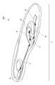
- FIG. 2 is a diagram illustrating an insole as an example of an article on which a transmission device used in this service is mounted.
- the transmission device 1 used in this service can be mounted on a shoe insole 500.
- the transmitting device 1 mounted on the shoe insole 500 in this manner (or the insole 500 mounted with the transmitting device 1) is hereinafter referred to as an “insole type transmitting device 1”.
- the insole type transmitting device 1 is mounted in advance on the shoes worn by the subject H (laid on the inside of the shoes), so that whenever the subject H steps on the shoes (insole 500), the subject Person information can be transmitted.
- the transmission device 1 includes a management unit 11, a detection unit 12 that detects pressure, and a power supply unit 13.
- a flexible substrate F is connected between the management unit 11 and the detection unit 12 and between the management unit 11 and the power supply unit 13.
- the specific aspect of the flexible substrate F is later mentioned with reference to FIG.
- the arrangement of the management unit 11, the detection unit 12, and the power supply unit 13 illustrated in FIG. 2 is an example, and is not limited to the arrangement illustrated in FIG.
- the management unit 11 and the power supply unit 13 may be placed at a position where a load is not applied as much as possible based on an opinion of an expert related to the sole (for example, an expert of plantar plate therapy).
- the subject H has an arrangement in which both the wearability of the insole 500 and ease of walking (healthy walking) are compatible.
- the management unit 11 includes a board that manages target person information.
- substrate which comprises the management part 11 is not specifically limited, From the structure embedded in the insole 500, it is preferable that it is a small board
- the size of the substrate constituting the management unit 11 is preferably about 19 mm in length, about 26 mm in width, and about 2.6 mm in thickness.
- the detection unit 12 detects a physical quantity based on pressure. Specifically, the detection unit 12 detects the treading force generated by the subject H walking (stepping on).
- the detection unit 12 can be configured by, for example, a piezoelectric element as an element that converts a force applied to a piezoelectric body into a voltage. In other words, the detection unit 12 can be configured by a piezoelectric element or the like that converts a physical quantity based on pressure into an electrical signal.
- the power supply unit 13 supplies power to the management unit 11.
- the power supply unit 13 is constituted by a battery or the like, but the life of the battery or the like is preferably longer than the product life of the insole 500.
- the product life of the insole 500 varies depending on the usage, but for daily use such as walking, it is about 1 year to 1 year and a half, and for light exercise such as sports, the life is about 6 months to 9 months. Become. In the case of intense exercise such as marathon or running, it is 500 km to 1000 km, and in the case of use less frequently such as climbing, the life is 2 to 3 years.
- the main intended use is daily use such as walking, and the life of the insole 500 is about one year to one and a half years, but this is a value that assumes daily use, In reality, it can be assumed that the lifetime is 2 to 3 years. For this reason, in order to eliminate the need to replace or charge the battery of the transmitter 1, a battery life of about 3 years is required, but according to the present invention, a battery life exceeding 3 years can be realized. Can do. A specific basis for realizing a battery life exceeding 3 years will be described later.
- the specific mode of the insole 500 main body is not particularly limited, but it is preferable to use a material or a shape that is resistant to the penetration of water and dust into the substrate constituting the management unit 11.
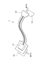
- FIG. 3 is a diagram showing an example of the flexible substrate F shown in FIG.
- the flexible substrate F is a substrate composed of an electronic component 101 and a connector 102.
- the electronic component 101 constitutes the management unit 11 in FIG.
- the connector 102 is a part that electrically connects the management unit 11 (electronic component 101) to the detection unit 12 and the power supply unit 13. Both the electronic component 101 and the connector 102 are lined with a reinforcing material 103.
- the flexible substrate F can be formed of a thin and soft substrate that can be bent or folded. Thereby, even if the transmitter 1 is embedded in a material that can be bent flexibly, such as the insole 500, there is no risk of breakage or the like.
- FIG. 4 is an image diagram illustrating an example of the configuration of the insole type transmission device 1.
- the configuration shown in FIG. 4 is a specific example for explaining the outline of the service, and the functional configuration of the transmission device 1 will be described later with reference to FIG.
- the detection unit 12 (for example, a piezoelectric element) generates power with the pedal force of the subject H and inputs power to the power supply IC 110.
- step S12 the power supply unit 13 (for example, a battery) constantly supplies power to the power supply IC 110. However, control of power supply from the power supply unit 13 to the power supply IC 110 is executed by the power supply IC 110.
- the power supply unit 13 for example, a battery
- step S ⁇ b> 13 the power supply IC 110 inputs power to the transmission unit 112.
- step S14 the transmitter 112 transmits a radio wave on which the subject information is superimposed.
- the transmission unit 112 it is preferable to employ a low power consumption communication method such as BLE (Blue Tooth Low Energy) (registered trademark).
- BLE Bluetooth Tooth Low Energy
- the battery life is about 8 months to 1 year if it is configured to transmit every second with a conventional beacon or the like. turn into. That is, when the battery capacity is 165 mAh and the power consumption per beacon transmission is 80 ⁇ Ws, the battery life is 257.8 days.
- the lifetime of the battery is about 3 to 7 years, and the lifetime is dramatically extended. That is, when the average number of steps per day of the subject H is 10800 steps and the life / death monitoring radio wave is generated every 30 seconds, the life of the battery is 2690.22 days. Thereby, since the life of the power supply unit 13 can be dramatically extended, a material that extends the life of the insole 500 while satisfying the condition that the life of the power supply unit 13 is longer than the life of the insole 500 is adopted. Can do.
- the specific size of the transmission part 112 is not specifically limited. For example, when the transmitter 112 is a BLE module, it can be about 7.9 mm long and about 11.5 mm wide. Moreover, it is preferable that the thickness of the whole management part 11 containing a BLE module shall be about 2.6 mm.
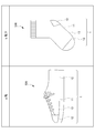
- FIG. 5 is a diagram showing the thickness of the insole type transmission device 1.
- the insole type transmitter 1 having a thickness X of about 10 mm is used.
- the subject person H can obtain a degree of freedom of wearing and can deal with a wide variety of shoes (footwear). That is, the insole type transmission device 1 can be worn on the shoes that the subject person H is familiar with.
- FIG. 6 is a schematic diagram showing an example of an article on which the transmission device used in the service of FIG. 1 is mounted, and an example different from the example of FIG.
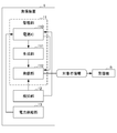
- FIG. 6 is a block diagram illustrating an example of a functional configuration of the transmission device 1.
- the transmission device 1 includes a management unit 11, a detection unit 12, and a power supply unit 13.
- the management unit 11 includes a power supply IC 110, a generation unit 111, and a transmission unit 112.
- the power supply IC 110 inputs power to the generation unit 111 and the transmission unit 112 using the input of power from the detection unit 12 as a trigger.
- the generation unit 111 generates target person information using the power input from the power supply IC 110.
- the transmission unit 112 transmits the target person information generated by the generation unit 111 using the power input from the power supply IC 110.
- the target person information transmitted from the transmitter 112 is received by the receiver R.
- the detection unit 12 generates electric power with the treading force of the target person H and inputs electric power to the power supply IC 110.
- the power supply unit 13 constantly supplies power to the power supply IC 110. However, control of power supply from the power supply unit 13 to the power supply IC 110 is executed by the power supply IC 110.
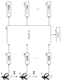
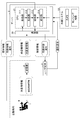
- FIG. 8 is a diagram showing the configuration of the information processing system of the present invention.
- the information processing system shown in FIG. 8 includes a transmitting device 1, a server 2, receivers R1 to Rm (m is an integer value of 1 or more), and user terminals 3-1 to 3-p (p is an integer of 1 or more). Numerical value).
- a transmitting device 1 a server 2
- receivers R1 to Rm m is an integer value of 1 or more
- user terminals 3-1 to 3-p p is an integer of 1 or more. Numerical value
- Numerical value Numerical value
- the transmitting device 1 and the receivers R1 to Rm can be connected by predetermined wireless communication including short-range wireless communication such as BLE.
- the server 2, the receivers R1 to Rm, and the user terminals 3-1 to 3-p are connected to each other via a predetermined network N such as the Internet.
- the subject terminal 4 operated by the subject H is also connected to each other via the network N.
- the transmission device 1 is a device mounted on an insole 500 of a shoe worn by the subject person H. Specifically, the transmission device 1 transmits the subject information in response to the pedaling force of the subject H.
- the transmission device 1 is composed of, for example, a beacon.
- the receivers R1 to Rm receive the target person information transmitted from the transmission device 1 and transfer it to the server 2 together with the receiver position information of the own device.
- the receivers R1 to Rm receive the target person information transmitted from the transmission device 1 and transfer it to the server 2 together with the receiver position information of the own device.
- the server 2 is an information processing apparatus managed by a service provider (not shown).
- the server 2 executes various processes for realizing this service while appropriately communicating with the receivers R1 to Rm and the user terminals 3-1 to 3-p. Further, the server 2 detects the going out of the target person H by performing analysis based on the target person information and the receiver position information. In addition, the server 2 notifies the user terminal 3 that the target person H has gone out.
- Each of the user terminals 3-1 to 3-p is an information processing apparatus operated by each of the users U1 to Up (FIG. 1).
- Each of the user terminals U1 to Up is configured by a personal computer, a smartphone, a tablet, or the like.
- Each of the user terminals 3-1 to 3-p accepts an input operation necessary for each of the users U1 to Up to use this service, and transmits information indicating the input contents to the server 2.
- each of the user terminals 3-1 to 3-p displays various information transmitted from the server 2 under the control of the user terminal 3-1 or the server 2 itself.
- a dedicated application for receiving provision of the service is installed in each of the user terminals 3-1 to 3-p.
- the user U when it is expressed as “the user U operates the user terminal 3”, it means that the user U activates a dedicated application installed in the user terminal 3 and performs various operations. It means that.
- the user terminals 3-1 to 3-p are collectively referred to as “user terminal 3”.
- the receivers R1 to Rm when it is not necessary to distinguish each of the receivers R1 to Rm, these are collectively referred to as “receiver R”.
- a service provider (not shown) can provide a service that is highly convenient for the user U and the target person H.
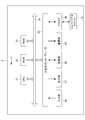
- FIG. 9 is a block diagram illustrating an example of a hardware configuration of the server 2 configuring the information processing system of FIG.
- the server 2 includes a CPU (Central Processing Unit) 21, a ROM (Read Only Memory) 22, a RAM (Random Access Memory) 23, a bus 24, an input / output interface 25, an input unit 26, an output unit 27, A storage unit 28, a communication unit 29, and a drive 30.
- CPU Central Processing Unit
- ROM Read Only Memory
- RAM Random Access Memory
- the CPU 21 executes various processes according to a program recorded in the ROM 22 or a program loaded from the storage unit 28 to the RAM 23.
- the RAM 23 appropriately stores data necessary for the CPU 21 to execute various processes.
- the CPU 21, ROM 22, and RAM 23 are connected to each other via a bus 24.
- An input / output interface 25 is also connected to the bus 24.
- An input unit 26, an output unit 27, a storage unit 28, a communication unit 29, and a drive 30 are connected to the input / output interface 25.
- the input unit 26 is configured with various hardware buttons and the like, and inputs various information according to an instruction operation by the operator.
- the output unit 27 is configured by a display such as a liquid crystal and displays various images.
- the storage unit 28 is configured by a DRAM (Dynamic Random Access Memory) or the like, and stores various data.
- the communication unit 29 controls communication with other devices (receivers R1 to Rm and user terminals 3-1 to 3-p) via the network N including the Internet.
- the drive 30 is provided as necessary.
- a removable medium 41 made of a magnetic disk, an optical disk, a magneto-optical disk, a semiconductor memory, or the like is appropriately worn on the drive 30.
- the program read from the removable medium 41 by the drive 30 is installed in the storage unit 28 as necessary.
- the removable medium 41 can also store various data stored in the storage unit 28 in the same manner as the storage unit 28.
- the receiver R, the user terminal 3, and the target person terminal 4 (not shown) in the information processing system of FIG. 8 also have the hardware configuration shown in FIG.
- the input unit 26 and the output unit 27 have touch panels.
- the “information generation process” refers to a process in which the server 2 generates information indicating the position and state of the target person H based on the acquired target person information and the receiver position information.
- the “information providing process” refers to a process in which the server 2 provides information indicating the generated position and state of the target person H to the user U.
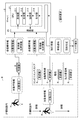
- FIG. 10 is a functional block diagram showing a functional configuration for executing the information providing process among the functional configurations of the information processing system including the server 2 of FIG.
- an acquisition unit 211 and a generation unit 212 function.
- the providing unit 213 and the receiving unit 214 function as necessary.
- the acquisition unit 211 acquires receiver information transmitted from each of the receivers R1 to Rm.
- the “receiver information” refers to information including target person information transmitted from the transmitting device 1 and received by the receiver R, and receiver position information.
- the generation unit 212 Based on the receiver information acquired by the acquisition unit 211, the generation unit 212 generates information indicating the status of the target person H (hereinafter referred to as “current status information”). Specifically, the generation unit 212 generates current status information by analyzing the receiver information.
- the accepting unit 214 accepts each of the information (hereinafter referred to as “providing request”) transmitted by each of the user terminals 3-1 to 3 -p indicating that the current status information of the target person H is requested.
- the providing unit 213 transmits each of the current status information generated by the generating unit 212 to each of the user terminals 3-1 to 3-p. Specifically, when the provision unit 213 receives a provision request, the provision unit 213 transmits current state information corresponding to the provision request to the user terminal 3. Further, the server 2 can independently determine and transmit without assuming the provision request.
- Each process such as an information providing process can be executed by the server 2 having the above functional configuration.
- the service provider can provide the user U and the target person H with the highly convenient service.
- FIG. 11 is an image diagram showing a case where the information processing system including the server 2 having the functional configuration shown in FIG. 10 is applied to the eyelid search service.
- the target person information transmitted from the transmission device 1 is installed in the site of the care facility B. Received by the receiver R. The target person information received by the receiver R is transmitted to the server 2 as receiver information together with the receiver position information. Then, the server 2 acquires the transmitted receiver information, executes the information providing process described above, and transmits the current status information to the user terminal 3. Thereby, the user U can easily recognize that the target person H is in the site of the care facility B from the current state information transmitted to the user terminal 3.
- the target person information transmitted from the transmission device 1 is It is received by each of the receivers R installed outside the site of the facility B.
- the receiver R can be installed or mounted on, for example, a convenience store, a vending machine, a utility pole, or a collaborator terminal (for example, a smartphone or a tablet) managed by a collaborator.
- the target person information received by the receiver R is transmitted to the server 2 as receiver information together with the receiver position information.
- the server 2 acquires the transmitted receiver information, executes the information providing process described above, and transmits the current status information to the user terminal 3.
- the current status information transmitted from the server 2 to the user terminal 3 includes information such as an alert notification indicating that the target person H is hesitant.
- the user U is outside the facility of the care facility B from the current status information that has been automatically notified of the alert without performing an operation of transmitting a provision request to the server 2 (hesitantly) Can be recognized immediately.
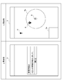
- FIG. 12 is a diagram showing a specific example of the current status information that is automatically notified of alerts from the server 2 to the user terminal 3.
- this service includes a service for detecting the habit of the target person H.
- the specific example a shown in FIG. 12 shows a specific example of the screen of the user terminal 3 when a message indicating that a wrinkle has been detected is automatically displayed as an alert. That is, when the target 2's trap is detected by the server 2, a message such as “detected trap” or “Mr. A's (target H) trap” pops up on the screen of the user terminal 3, for example. Is done. The message pop-up displayed on the screen of the user terminal 3 can be closed by pressing a button labeled “Close”.
- the specific example b shown in FIG. 12 shows a specific example when a map showing the position of the deaf person is displayed on the screen of the user terminal 3. That is, when the target person H's trap is detected by the server 2, information indicating the current location of the target person H detected as a trap, information indicating the position of the care facility B, on the screen of the user terminal 3, The information indicating the safe area Sa, the information indicating the position of the receiver R, the area Da capable of displaying the predetermined information, and the like are displayed together with the map.
- FIG. 13 is an image diagram showing a case where an information processing system including the server 2 having the functional configuration shown in FIG. 10 is applied to an independent support service.
- This service includes a service that supports the independence of the target person H (hereinafter referred to as “independence support service”). As shown in FIG. 13, when the target person H wearing the transmission device 1 is walking in the site of the care facility B, the target person information transmitted from the transmission device 1 is installed in the site of the care facility B. Received by the receiver R.
- the subject information can include the context information of the subject H.
- the “context” is a concept indicating all of the internal state and the external state of the subject H.
- the internal state of the subject person H refers to the physical condition of the subject person H, emotion (feeling or psychological state), or the like.
- the external state of the subject person H is the space around the subject person H in addition to the spatial or temporal placement position of the subject person H (the temporal placement position refers to the current time, for example). It also refers to a predetermined state distributed in the direction or time direction (or distributed in any direction).
- the context information includes, for example, information on the activity of the subject H (number of steps, etc.), information on stress, information on the environment, subjective information on physical condition, age, height, weight, body temperature, and body fat percentage of the subject H.
- the objective information regarding the physical characteristics of the subject person H, and the information regarding the schedule of the subject person H such as the action history of the subject person H can be included.
- the specific method by which the server 2 acquires context information is not particularly limited.
- information provided from an external server may be acquired as context information, or the transmitter 1 may be provided with various sensors (not shown), and information detected by these sensors may be acquired as context information. Also good.
- you may acquire the information separately managed in the facilities etc. which the user U manages, such as care facility B, as context information.
- the target person information received by the receiver R is transmitted to the server 2 as receiver information together with the receiver position information. Then, the server 2 acquires the received receiver information, generates the current state information by executing the above-described information providing process, and transmits it to the user terminal 3.
- the server 2 together with the receiver position information, information for uniquely identifying the target person H (hereinafter referred to as “target person ID”) and information regarding the number of steps of the target person H (hereinafter referred to as “step number information”). )) And information about the stress distribution (stress distribution information) at least.
- the server 2 generates the current state information by executing the above-described information providing process, but in the example of FIG. 13, the current state information including information indicating the “degree of independence” of the target person H is generated.
- the “degree of independence” refers to an index that indicates how much the target person H can live in daily life without requiring the power of others.
- the degree of independence can be calculated based on the context information included in the target person information. Specifically, for example, information managed in the external system SS managed by the care facility B and information detected by various sensors (not shown) of the transmission device 1 are acquired as context information, and the context information is included in this context information. Based on this, the degree of independence is calculated.
- the server 2 transmits information indicating the calculated degree of independence of the target person H to the user terminal 3. Thereby, the user U can easily grasp the current state of the target person H from the current state information transmitted to the user terminal 3 and including information indicating the degree of independence.
- FIG. 14 is an image diagram showing a case where an information processing system including the server 2 having the functional configuration shown in FIG. 10 is applied to a vision support service.
- This service includes a service (hereinafter referred to as “sight support service”) that supports the subject H who has a handicap in visual acuity such as amblyopia.
- the target person H who receives the provision of the visual acuity support service carries the target person terminal 4 and acquires the current status information using the target person terminal 4. Specifically, for example, the target person H can acquire the current state information through hearing through the earphone Y connected to the target person terminal 4.
- the target person information transmitted from the transmitting device 1 is a receiver installed in the site of the nursing facility B. Received by R.
- the subject information includes the context information of the subject H acquired by the above-described method.
- the target person information including the context information received by the receiver R is transmitted to the server 2 as receiver information together with the receiver position information. Then, the server 2 acquires the received receiver information, generates the current status information by executing the above-described information providing process, and transmits the current status information to the target person terminal 4 and the user terminal 3.
- the server 2 acquires information necessary for supporting the visual acuity of the target person H (hereinafter, “sight support information”) from the external system SS together with the receiver information, and based on the acquired information. Then, the information providing process described above is executed.
- the external system SS includes imaging means (for example, a camera) that can image the subject H, sensing equipment that can acquire information indicating the state of the subject H, and the like.
- the “sight support information” includes data of the captured image of the subject H captured by the imaging means of the external system SS and information indicating the state of the subject H detected by the sensing device.
- the server 2 generates the current status information based on the receiver information and the vision support information.
- information for preventing an accident of the target person H (hereinafter referred to as “accident prevention information”).
- current information including information for improving care work for the target person H by the caregiver (hereinafter referred to as “work improvement information”) is generated.
- the server 2 appropriately transmits current status information including the generated accident prevention information and business improvement information to the target person terminal 4 and the user terminal 3.
- the subject person H can depend on the present condition information containing the accident prevention information transmitted to the subject person terminal 4, and can send a daily life.
- the user U can easily acquire information necessary for business improvement based on the current status information including the business improvement information transmitted to the user terminal 3.
- FIG. 15 is an image diagram showing a case where an information processing system including the server 2 having the functional configuration shown in FIG. 10 is applied to a sports data providing service.
- This service includes a service (hereinafter referred to as “sports data providing service”) that supports a user U (for example, a coach or the like) who is in a position to support the target person H who is a sports player.
- sports data providing service a service that supports a user U (for example, a coach or the like) who is in a position to support the target person H who is a sports player.
- the user U who receives the provision of the sports data providing service wears sports shoes 500 on which the transmission device 1 is mounted and performs sports.
- the target person information is transmitted from the transmission device 1 by the target person H running.
- the target person information transmitted from the target person H includes at least a target person ID, step count information, and stress distribution information.
- the target person information transmitted from the transmitting device 1 is received by the receiver R installed in the site of the care facility B.
- the target person information including the context information received by the receiver R is transmitted to the server 2 as receiver information together with the receiver position information.
- the server 2 acquires the received receiver information, generates the current status information by executing the above-described information providing process, and sends the current status information to the target terminal 4 (not shown) and the user terminal 3. Send.
- the server 2 acquires information for supporting the user U who supports the target person H who performs sports as context information from the external system SS together with the receiver information, and based on these acquired information, The information providing process described above is executed.
- the external system SS includes an imaging unit (for example, a camera) that can capture an image of the subject person H who performs sports, a sensing device that can acquire information indicating the state of the target person H, and the like.
- the context information provided by the external system SS includes data of the captured image of the subject person H captured by the imaging means of the external system SS and information indicating the state of the subject person H detected by the sensing device. included.
- the server 2 generates the current state information based on the receiver information and the context information provided by the external system SS.
- information indicating the amount of exercise of the subject H (hereinafter, “exercise amount information”). )
- technical information (hereinafter referred to as “technical information”) such as how to step on the foot of the subject H, and the like.
- the technical information for example, information on how to step on the jump crossing is compared with first-class player information (example information).
- the server 2 appropriately transmits current status information including the generated exercise amount information and technical information in response to a provision request from the user terminal 3. Accordingly, the user U can appropriately support the target person H by referring to the current state information including the exercise amount information and the technical information transmitted from the server 2 to the user terminal 3.
- FIG. 16 is an image diagram showing a case where an information processing system including the server 2 having the functional configuration shown in FIG. 10 is applied to a tracking service.
- This service includes a service (hereinafter referred to as a “tracking service”) that supports management operations of the manager of the ski facility and the like by tracking the user and mountain climber of the ski facility.
- a target person H a ski facility user or a mountain climber
- the target person information is transmitted from the transmission device 1 as the target person H walks.
- the target person information transmitted from the target person H includes at least information (for example, a beacon signal) used for specifying the position of the transmission device 1.
- the target person information transmitted from the transmitting device 1 is received by the receiver R installed in the site of the ski facility or on the mountain path.
- the target person information received by the receiver R is transmitted to the server 2 as receiver information together with the receiver position information.
- the server 2 acquires the received receiver information, generates the current status information by executing the above-described information providing process, and sends the current status information to the target terminal 4 (not shown) and the user terminal 3. Send.
- the server 2 generates the current status information based on the receiver information.
- the current status information including information indicating the position of the target person H is generated.
- alert information or the like is generated as current information.
- the server 2 appropriately transmits the current status information including the generated information indicating the position of the target person H and the alert information to the user terminal 3. Thereby, the user U can take an appropriate response based on the current state information transmitted from the server 2 to the user terminal 3.
- FIG. 17 is an image diagram showing a case where an information processing system including the server 2 having the functional configuration shown in FIG. 10 is applied to an operation management support service.
- This service detects the accelerator work of the subject person H who drives the car and supports the person (user U) who manages the driving of the subject person H, including prevention of traffic accidents (hereinafter referred to as “driving management”). Called support services).
- driving management the target person H to be managed wears shoes equipped with the transmission device 1 and drives the automobile. Thereby, for example, subject person information is transmitted from transmitting device 1 when subject person H steps on an accelerator pedal or a brake pedal.
- the target person information transmitted from the transmitting device 1 is received by the receiver R installed in the car.
- the target person information received by the receiver R is transmitted to the server 2 as receiver information together with the receiver position information.
- the server 2 acquires the received receiver information, generates the current status information by executing the above-described information providing process, and sends the current status information to the target terminal 4 (not shown) and the user terminal 3. Send.
- the server 2 acquires information for supporting the person (user U) who manages the driving of the target person H as context information from the external system SS together with the receiver information, and based on the acquired information. Then, the information providing process described above is executed.
- the external system SS includes an imaging means (for example, a camera) that can image the subject person H who drives the car, a sensing device that can acquire information indicating the state of the subject person H, and the like.
- the context information provided by the external system SS includes data of the captured image of the subject person H captured by the imaging means of the external system SS and information indicating the state of the subject person H detected by the sensing device. included.
- the server 2 generates the current status information based on the receiver information and the context information provided by the external system SS.
- information on driving technology including the accelerator work of the target person H (
- current status information including the “driving technology information”) and personal information of the target person H (hereinafter referred to as “personality information”) is generated.
- personal information including the “driving technology information”
- alert information or the like is generated as the current state information.
- the server 2 appropriately transmits current status information including the generated driving information and technical information in response to a provision request from the user terminal 3.
- the alert information is transmitted regardless of whether there is a provision request from the user terminal 3.
- the person (user U) who manages the driving of the target person H refers to the current state information including the driving technique information, the personality information, and the alert information transmitted from the server 2 to the user terminal 3.
- the operation of H can be managed appropriately.
- FIG. 18 is an image diagram showing a case where an information processing system including the server 2 having the functional configuration shown in FIG. 10 is applied to a factory management support service.
- This service includes a service (hereinafter referred to as “factory management support service”) that detects the behavior of the target person H engaged in work as a worker in a factory facility and supports a person (user U) who manages the factory facility. Call).
- the factory management support service As shown in FIG. 18, according to the factory management support service, the target person H to be managed in the factory facility engages in work while wearing work shoes 100 on which the transmission device 1 is mounted. Accordingly, the subject person information is transmitted from the transmission device 1 in accordance with an action such as the subject person H walking in the factory.
- the target person information transmitted from the transmitting device 1 is received by the receiver R installed in the factory facility.
- the target person information received by the receiver R is transmitted to the server 2 as receiver information together with the receiver position information.
- the server 2 acquires the transmitted receiver information, generates the current status information by executing the above-described information providing process, and transmits the current status information to the user terminal 3.
- the server 2 acquires, as context information, information useful for supporting a person (user U) who manages the behavior of the target person H in the factory facility from the external system SS together with the receiver information. Based on the acquired information, the information providing process described above is executed.
- the external system SS includes an imaging means (for example, a camera) that can capture an image of the subject person H engaged in work in the factory facility, a sensing device that can acquire information indicating the state of the subject person H, and the like.
- the context information provided by the external system SS includes data of the captured image of the subject person H captured by the imaging means of the external system SS and information indicating the state of the subject person H detected by the sensing device. included.
- the server 2 generates the current state information of the target person H based on the receiver information and the context information provided by the external system SS. In the example of FIG. 18, it is necessary for improving the work in the factory. Current status information including information to be generated is generated. Further, when the target person H enters a dangerous zone in the factory, alert information or the like is generated as the current status information.
- the server 2 appropriately transmits the generated current status information in response to a provision request from the user terminal 3.
- the alert information is transmitted regardless of whether there is a provision request from the user terminal 3.
- the person (user U) who manages the behavior of the target person H in the factory facility can obtain information and alert information necessary for improving the work in the factory transmitted from the server 2 to the user terminal 3.
- the behavior of the target person H in the factory facility can be appropriately managed. In addition, it is possible to improve operations in factory facilities.
- the target person information transmitted from the transmission device 1 does not include information indicating the position of the transmission device 1. That is, the current location of the transmission device 1 is specified based on the information indicating the position of the receiver R that has received the target person information transmitted from the transmission device 1.
- Information indicating the position of the transmission device 1 may be included in the target person information transmitted from the transmission device 1.
- the transmission device 1 is mounted on the insole 500.
- the transmission device 1 is not particularly limited thereto.
- the transmission device 1 may be attached to an arbitrary portion of the foot of the subject H.
- the method used for transmitting information from the transmitting device 1 is a method for transmitting a beacon signal compliant with Bluetooth (registered trademark).
- a system using a set of LPRa (Low Power Wide Area) + GPS (Global Positioning System) by LoRa may be used.
- the power source of the transmission device 1 is configured to employ a battery such as a button battery or a magnesium battery, but is not particularly limited thereto, and may be an external power source or automatic power generation. But you can.
- the automatic power generation method is not particularly limited, and any surface current, thermoelectric power generation, power generation fiber, or the like can be employed.
- the electric power generated by the automatic power generation may be stored.
- the method for storing electricity is not particularly limited, and for example, a method using a magnesium battery or a super capacitor can be employed.
- a piezoelectric element that generates electric power when the subject H steps on the insole 500 is used as the detection unit 12 of the transmission device 1, but is not particularly limited thereto.
- Various sensors such as an acceleration sensor, a gyro sensor, and a temperature sensor can be used.
- the service can be used in the user terminal 3 and the target person terminal 4 by starting the dedicated application installed in the user terminal 3 and the target person terminal 4.
- the service may be used by accessing a predetermined website and performing a predetermined login operation without installing a dedicated application.
- system configuration shown in FIG. 8 and the hardware configuration of the server 2 shown in FIG. 9 are merely examples for achieving the object of the present invention, and are not particularly limited.
- FIGS. 7 and 10 are merely examples, and are not particularly limited. That is, it is sufficient that the information processing apparatus or the information processing system has a function capable of executing the above-described series of processes as a whole, and what functional blocks are used to realize this function are particularly illustrated in FIG. It is not limited to the example of FIG.
- the location of the functional block is not limited to that shown in FIGS. 7 and 10 and may be arbitrary.
- one functional block may be constituted by hardware alone, software alone, or a combination thereof.
- a program constituting the software is installed on a computer or the like from a network or a recording medium.
- the computer may be a computer incorporated in dedicated hardware.
- the computer may be a computer capable of executing various functions by installing various programs, for example, a general-purpose smartphone or personal computer other than a server.
- a recording medium including such a program is not only constituted by a removable medium distributed separately from the apparatus main body in order to provide the program to each user, but also provided to each user in a state of being incorporated in the apparatus main body in advance. It is composed of a provided recording medium or the like.
- the steps for describing the program recorded on the recording medium are not limited to the processing performed in time series according to the order, but may be performed in parallel or individually even if not necessarily performed in time series.
- the process to be executed is also included.
- system means an overall apparatus composed of a plurality of devices, a plurality of means, and the like.
- the information processing apparatus to which the present invention is applied only needs to have the following configuration, and can take various embodiments. That is, the information processing apparatus to which the present invention is applied (for example, the transmitting apparatus 1 in FIG. 1) Detection means (for example, the detection unit 12 in FIG. 7) for detecting a physical quantity based on pressure from at least a part of the human foot (for example, the sole of the foot) When the physical quantity detected by the detection unit satisfies a predetermined standard (for example, when a predetermined threshold is exceeded), a transmission unit (for example, the transmission unit 112 in FIG. 7) that transmits predetermined information; Is provided.
- a predetermined standard for example, when a predetermined threshold is exceeded
- the transmission means can transmit information used for specifying a position where the own device is present as the predetermined information.
- the information processing apparatus is mounted on an article (for example, the insole 500) in contact with or close to the person's foot,
- the detection means can detect a pedaling force or a physical quantity based on the pedaling force.
- the subject person H can transmit information indicating the current state including his / her current position to the other person only by wearing the insole 500.
- an information processing system of one embodiment of the present invention includes: A first information processing device (for example, the transmitting device 1 in FIG. 8) worn on an article that is in contact with or close to the foot of a person (for example, the subject person H), and a second information processing device (for example, a predetermined processing related to the person)
- the first information processing apparatus Detecting means for detecting a physical quantity based on pressure from at least a part of the person's foot for example, the detecting unit 12 in FIG.
- a transmission means for transmitting the first information for example, the transmission unit 112 in FIG. 7
- the second information processing apparatus Acquisition means for acquiring the first information for example, the acquisition unit 211 in FIG. 10
- Execution means for example, the generation unit 212 and the provision unit 213 in FIG. 10 that executes the predetermined process based on the first information; Is provided.
- the target person H can easily acquire information indicating the current state of the target person H who is difficult to transmit information indicating his / her current state to others.
- the acquisition unit further acquires second information (for example, context information) indicating a context related to the person.
- the execution means can execute the predetermined process based on the second information in addition to the first information.
- the target person H can easily acquire information indicating the current state of the target person H that is difficult to convey to the other person information indicating the current state including context information.
- the execution means can execute the predetermined process using the position of the person specified based on the first information.
- the target person H can easily acquire information indicating the current state of the target person H who is difficult to transmit information indicating the current state including the current location to other persons.
- the second information processing apparatus may transmit some information such as a result of a predetermined process as FB information to the first information processing apparatus.
- the server 2 may transmit information provided to the user U (information indicating the current position of the subject person H, the culling route, etc.) to the transmitting device 1.
- the transmission device 1 may have a function of receiving the information and a function of notifying the user U of the information or information based on the information.
- the transmission device 1 may notify the target person H of the current position of the target person H, or notify the target person H of any warning if the current position of the target person H is a position to be warned. May be.
- the notification method in this case is not particularly limited, and in addition to a method of notifying by an output mechanism (speaker, display, etc.) possessed by the transmission device 1 itself, a device other than the transmission device 1 (for example, the target person H) Arbitrary methods such as a method of informing by a wearable device (not shown) that is held may be employed.
Abstract
Description
ここで、このような課題は、高齢者のみならず、自身の現状を示す情報(例えば位置を示す情報)を他者に伝達することが困難な者一般に対して当てはまる。 However, in the prior art including
Here, such a problem applies not only to elderly people but also to general people who have difficulty in transmitting information indicating their current state (for example, information indicating a position) to others.
人の足の少なくとも一部からの圧力に基づく物理量を検知する検知手段と、
前記検知手段により検知された前記物理量が所定基準を満たした場合、所定情報を発信する発信手段と、
を備える。 In order to achieve the above object, an information processing apparatus of one embodiment of the present invention provides:
Detecting means for detecting a physical quantity based on pressure from at least a part of a person's foot;
A transmitting means for transmitting predetermined information when the physical quantity detected by the detecting means satisfies a predetermined standard;
Is provided.
前記検知手段は、踏力又はその踏力に基づく物理量を検知することができる。 The information processing apparatus is mounted on an article that is in contact with or close to the person's foot,
The detection means can detect a pedaling force or a physical quantity based on the pedaling force.
人の足に接触又は近接する物品に着用される第1情報処理装置と、当該人に関する所定処理を実行する第2情報処理装置とを含む情報処理システムであって、
前記第1情報処理装置は、
前記人の足の少なくとも一部からの圧力に基づく物理量を検知する検知手段と、
前記検知手段により検知された前記物理量が所定基準を満たした場合に、第1情報を発信する発信手段と、
を備え、
前記第2情報処理装置は、
前記第1情報を取得する取得手段と、
前記第1情報に基づいて、前記所定処理を実行する実行手段と、
を備える。 In order to achieve the above object, an information processing system of one embodiment of the present invention includes:
An information processing system including a first information processing device worn on an article that is in contact with or close to a person's foot and a second information processing device that executes a predetermined process related to the person,
The first information processing apparatus
Sensing means for sensing a physical quantity based on pressure from at least a portion of the person's foot;
Transmitting means for transmitting the first information when the physical quantity detected by the detecting means satisfies a predetermined standard;
With
The second information processing apparatus
Obtaining means for obtaining the first information;
Execution means for executing the predetermined process based on the first information;
Is provided.
前記実行手段は、前記第1情報に加えてさらに、前記第2情報に基づいて、前記所定処理を実行することができる。 In addition to the first information, the acquisition unit further acquires second information indicating a context related to the person,
The execution means can execute the predetermined process based on the second information in addition to the first information.
図1は、本発明が適用される情報処理システムにより実現可能な本サービスの概要を示す図である。 First, an outline of an example of a service that can be provided by an information processing system to which the present invention is applied (hereinafter referred to as “the present service”) will be described with reference to FIG.
FIG. 1 is a diagram showing an outline of this service that can be realized by an information processing system to which the present invention is applied.
このような本サービスに適用される情報処理システムは、対象者Hの足に着用される物品(例えばインソール)に搭載される発信装置1と、サーバ2と、受信機Rと、ユーザUにより操作されるユーザ端末3とを含む。
ここで、サーバ2は、本サービスの提供者(図示せず)により管理されているものとする。 In this service, when the elderly person who suffered from dementia is the subject person H, and the subject person H is lost in the streets, the current location of the subject person H and its history (eg, route) ) To the user U. Here, although the user U can also be the target person H, in this embodiment, the person U is a person other than the target person H and wants to check the status of the target person H, such as a family member or the like. It shall be the staff of nursing care facility B.
Such an information processing system applied to this service is operated by the
Here, it is assumed that the
この対象者情報は、所定距離しか届かないため、発信装置1(対象者H)から当該所定距離以内に存在する受信機Rにより受信される。
サーバ2は、受信機Rから対象者情報を受信した旨の通知を受け取ることで、当該受信機Rの位置を、対象者Hの現在状況を示す情報(以下、「現状情報」と呼ぶ)として生成する。
ここで、受信機Rは、既存の位置に予め固定されているものである。従って、サーバ2は、受信機Rの位置を予め登録しておいたり、その受信機Rの位置を示す情報(以下、「受信機位置情報」と呼ぶ)を当該受信機Rから受信することで、受信機Rの位置を容易に認識することができる。
サーバ2は、現状情報をユーザ端末3に送信する。ユーザUは、ユーザ端末3を介して現状情報を得ることで、対象者Hの現状(現在位置や徘徊ルート等)を認識することができる。 Specifically, for example, the transmitting
Since this target person information reaches only a predetermined distance, it is received by the receiver R existing within the predetermined distance from the transmitting device 1 (target person H).
The
Here, the receiver R is fixed to an existing position in advance. Accordingly, the
The
このため、本サービスによれば、対象者Hが、たとえ自分自身の状況を示す情報を他者に伝達することが困難な状況にあっても、ユーザUは、当該情報を容易に取得することができる。 Here, the target person H is not limited to an elderly person, but can be any person such as a person who has difficulty in transmitting information indicating his / her current state to another person.
For this reason, according to this service, even if the target person H is in a situation where it is difficult to transmit information indicating his / her own situation to others, the user U can easily acquire the information. Can do.
例えば介護施設Bでは、老人等の被介護者が対象者Hになる。当該対象者Hは、無断で外出して徘徊してしまうことが多々ある。
このとき、対象者Hは、自分自身の状況を示す情報(例えば自身の現在位置を示す情報)を他者に伝達することが困難な場合であっても、発信装置1を着用していれば、現状情報が生成・送信されるため、行方不明になることを防止することができる。
ここで、重要な点は、対象者Hが「発信装置1を着用していれば」という条件を満たす必要がある点である。
即ち、従来のような対象者Hが身に着けられるアクセサリ等の端末を発信装置1とすることも可能であるが、上述したように、徘徊時において対象者Hが端末等を身に着けていることはそもそも稀である。従って、従来の端末等では、対象者Hが「発信装置1を着用していれば」という条件をそもそも満たすことができない。
一方、対象者Hは、徘徊する場合であっても、普段から用いている靴を履いていることがほとんどである。そこで、本サービスでは、発信装置1はインソール(例えば後述する図2のインソール500)に搭載されており、当該インソールは、対象者Hが普段から用いている靴に予め(徘徊前から)敷かれている。これにより、対象者Hが「発信装置1を着用していれば」という条件を満たすことができる。 The service shown in FIG. 1 will be described in more detail.
For example, in a care facility B, a cared person such as an elderly person becomes the target person H. The subject person H often goes out and hesitates without permission.
At this time, even if it is difficult for the target person H to transmit information indicating his / her own situation (for example, information indicating his / her current position) to another person, the target person H may wear the
Here, an important point is that the subject H needs to satisfy the condition “if the
That is, a terminal such as an accessory that can be worn by the target person H as in the past can be used as the
On the other hand, even if the subject H is hesitant, he or she usually wears shoes normally used. Therefore, in this service, the transmitting
発信装置1は、踏力が一定以上等の所定基準を満たすことをトリガとして、対象者情報を発信する(ステップS1)。 That is, the
The
これにより、ユーザU(例えば介護施設Bの職員等)は、対象者Hが外出したことを容易に認識することができる。 The
Thereby, the user U (for example, the staff of the care facility B) can easily recognize that the target person H has gone out.
ユーザ端末3は、送信されてきた、対象者Hの現在位置を示す情報を含む現状情報を受信して表示する(ステップS11)。
これにより、ユーザU(例えば介護施設Bの職員)は、対象者Hの現在位置及びその履歴(徘徊ルート)を容易に認識することができる。 The
The
Thereby, the user U (for example, the staff of the care facility B) can easily recognize the current position of the target person H and the history (the habit route).
図2は、本サービスで使用される発信装置が搭載された物品の一例としてのインソールを示す図である。 Next, a specific example of the
FIG. 2 is a diagram illustrating an insole as an example of an article on which a transmission device used in this service is mounted.
インソールタイプの発信装置1は、対象者Hが履く靴に予め装着されている(靴の内側に敷かれている)ため、対象者Hが歩くことにより靴(インソール500)を踏む毎に、対象者情報を発信することができる。 As shown in FIG. 2, the
The insole
管理部11と検知部12との間、及び管理部11と電力供給部13との間は、いずれもフレキシブル基板Fで接続されている。なお、フレキシブル基板Fの具体的態様については、図3を参照して後述する。
ここで、図2に示す管理部11、検知部12、及び電力供給部13の配列は例示であり、図2に示す配置に限定されない。例えば、足底に関係する専門家(例えば足底板療法の専門家)の意見等に基づいて、管理部11及び電力供給部13はなるべく荷重がかからない位置としてもよい。
また、検知部12については、なるべく荷重がかかりやすい位置に配置することが好ましい。また、対象者Hにおける、インソール500の着用性と歩きやすさ(健康歩行)とを両立させた配置とすることが好ましい。 Specifically, the
A flexible substrate F is connected between the
Here, the arrangement of the
Moreover, it is preferable to arrange | position the
具体的には例えば、管理部11を構成する基板のサイズを、縦19mm程度、横26mm程度、厚さ2.6mm程度とすることが好ましい。 The
Specifically, for example, the size of the substrate constituting the
換言すると、検知部12は、圧力に基づく物理量を電気信号に変換する圧電素子等で構成させることができる。 The
In other words, the
インソール500の製品寿命は、使用用途によって差があるが、例えばウォーキングなどの日常使用の場合は1年~1年半程度であり、スポーツなどの軽い運動の場合は半年~9ケ月程度の寿命となる。また、マラソンやランニングなどの激しい運動の場合は500km~1000kmとなり、登山などの使用頻度が少ない使用の場合は2年~3年の寿命となる。
このうち、想定される主な使用用途は、ウォーキングなどの日常使用であり、インソール500の寿命は1年~1年半程度となるが、これは毎日使用した場合を想定した数値であるため、現実的には2年~3年の寿命であることが想定できる。
このため、発信装置1の電池交換や充電を行う必要がなくなるようにするためには、3年程度の電池寿命が必要となるが、本発明によれば3年を超える電池寿命を実現させることができる。なお、3年を超える電池寿命を実現させることができる具体的根拠については後述する。 The
The product life of the
Of these, the main intended use is daily use such as walking, and the life of the
For this reason, in order to eliminate the need to replace or charge the battery of the
図3には図示しないが、電子部品101は、図2の管理部11を構成するものである。コネクタ102は、管理部11(電子部品101)と、検知部12や電力供給部13とを電気的に接続する部位である。
電子部品101及びコネクタ102は、いずれも補強材103により裏打ちが施されている。
フレキシブル基板Fは、曲げたり折ったりすることができる薄くて柔らかい基板で構成させることができる。
これにより、発信装置1は、インソール500という柔軟に折り曲げることができる素材内に埋め込まれていたとしても、破損等のおそれがなくなる。 As shown in FIG. 3, the flexible substrate F is a substrate composed of an
Although not shown in FIG. 3, the
Both the
The flexible substrate F can be formed of a thin and soft substrate that can be bent or folded.
Thereby, even if the
図4は、インソールタイプの発信装置1の構成の一例を示すイメージ図である。なお、図4に示す構成は、本サービスの概要を説明するための具体例であり、発信装置1の機能的な構成については、図7を参照して後述する。 Next, with reference to FIG. 4, the mechanism by which the insole
FIG. 4 is an image diagram illustrating an example of the configuration of the insole
ステップS14において、発信部112は、対象者情報を重畳させた電波を発信する。ここで、発信部112としては、例えばBLE(BlueTooth Low Enagey)(登録商標)等の低消費電力の通信手法を採用するのが好ましい。
ここで、発信部112として、BLE等の低消費電力の通信手法を採用した場合であっても、従来からあるビーコン等で毎秒発信する構成とすると、電池の寿命は8カ月~1年程度となってしまう。即ち、電池の容量を165mAhとし、ビーコンの1発信あたりの消費電力量を80μWsとした場合、電池の寿命は257.8日となる。
これに対し、上述の構成(圧力素子を用いた構成)とした場合には、消費電力を抑えることができるので、電池の寿命は約3~7年となり、飛躍的に寿命が延びる。即ち、対象者Hの1日あたりの平均歩数を10800歩とし、死活監視用の電波を死活30秒毎に発生させることとした場合、電池の寿命は2690.22日となる。
これにより、電力供給部13の寿命を飛躍的に延ばすことができるので、電力供給部13の寿命がインソール500の寿命よりも長いという条件を満たしながら、インソール500の寿命を延ばす素材を採用することができる。
なお、発信部112の具体的なサイズは特に限定されない。例えば発信部112をBLEモジュールとした場合には、縦7.9mm程度、横11.5mm程度とすることができる。また、BLEモジューを含む管理部11全体の厚みを2.6mm程度とするのが好ましい。 In step S <b> 13, the
In step S14, the
Here, even when a low-power-consumption communication method such as BLE is adopted as the
On the other hand, in the case of the above-described configuration (configuration using a pressure element), power consumption can be suppressed, so that the lifetime of the battery is about 3 to 7 years, and the lifetime is dramatically extended. That is, when the average number of steps per day of the subject H is 10800 steps and the life / death monitoring radio wave is generated every 30 seconds, the life of the battery is 2690.22 days.
Thereby, since the life of the
In addition, the specific size of the
このため、従来からある徘徊探索用の機器の場合、専用の靴として使用することしかできないため、対象者Hにおける靴の選択肢の幅が狭くなってしまう。
また、不自然で不安定な底の厚い靴になってしまうため、高齢者に対し、安全かつ安定的な歩行を保証することができない。さらに、電池交換や充電が頻繁に必要になるため、見守りに係る製品としては好ましくない不測の電池切れが生じるおそれがある。 As a conventional device for heel search, there is a shoe incorporating a GPS (Global Positioning System) device. However, since the size and strength of the GPS are taken into consideration, a thick insole integrated with the shoes is used, and a part of the insole is cut out, and the GPS device is inserted into the cut out part. ing.
For this reason, in the case of a conventional device for searching for wrinkles, since it can only be used as a dedicated shoe, the range of shoe choices for the subject H is narrowed.
Moreover, since it becomes an unnatural and unstable thick shoe, it cannot guarantee a safe and stable walking for elderly people. Furthermore, since battery replacement and charging are frequently required, there is a risk that unexpected battery exhaustion, which is undesirable as a product for watching, may occur.
これにより、対象者Hは、着用の自由度を得ることができるとともに、多種多様の靴(履物)に対応することができる。
即ち、対象者Hが普段履き慣れた靴に、インソールタイプの発信装置1を着用させることもできる。 Therefore, the
Thereby, the subject person H can obtain a degree of freedom of wearing and can deal with a wide variety of shoes (footwear).
That is, the insole
図6は、図1の本サービスで使用される発信装置が搭載された物品の一例であって、図2の例とは異なる例を示す概要図である。 Next, an example in which the
FIG. 6 is a schematic diagram showing an example of an article on which the transmission device used in the service of FIG. 1 is mounted, and an example different from the example of FIG.
即ち、図6に示す例のa靴では、インソールに搭載された発信装置1を、靴500に着用させる(敷く)のではなく、靴そのものが、発信装置1が搭載された物品500として機能することとなる。 In the shoe a in the example shown in FIG. 6, an example in which the
That is, in the shoe a in the example shown in FIG. 6, the shoe itself does not wear (lay) the
即ち、図6に示す例のb靴下では、靴下そのものが、発信装置1が搭載された物品500として機能することとなる。これにより、靴を履かない環境における徘徊にも対応することができる。なお、靴を履かない環境としては、例えば広い室内、あるいは、靴を履かない状態での外出等を想定することができる。
[機能的構成]
図7は、発信装置1の機能的構成の一例を示すブロック図である。 In the example of the sock shown in FIG. 6, an example in which the
In other words, in the sock b of the example shown in FIG. 6, the sock itself functions as the
[Functional configuration]
FIG. 7 is a block diagram illustrating an example of a functional configuration of the
電源IC110は、検知部12から電力が入力されたことをトリガとして、生成部111と、発信部112とに電力を入力する。
生成部111は、電源IC110から入力された電力を用いて、対象者情報を生成する。
発信部112は、電源IC110から入力された電力を用いて、生成部111により生成された対象者情報を発信する。発信部112から発信された対象者情報は、受信機Rによって受信される。 The
The
The
The
図8は、本発明の情報処理システムの構成を示す図である。 Next, the configuration of an information processing system including the
FIG. 8 is a diagram showing the configuration of the information processing system of the present invention.
発信装置1と受信機R1乃至Rmとは、BLE等の近距離無線通信を含む、所定の無線通信によって接続可能となっている。サーバ2、受信機R1乃至Rm、及びユーザ端末3-1乃至3-pの夫々は、インターネット等の所定のネットワークNを介して相互に接続されている。
また、図示はしないが、対象者Hが操作する対象者端末4も、ネットワークNを介して相互に接続されている。 The information processing system shown in FIG. 8 includes a transmitting
The transmitting
Although not shown, the subject terminal 4 operated by the subject H is also connected to each other via the network N.
発信装置1は、対象者Hが履く靴のインソール500に搭載される装置である。具体的には、発信装置1は、対象者Hの踏力に反応して、対象者情報を発信する。発信装置1は、例えばビーコン等で構成される。 (Transmitting device)
The
受信機R1乃至Rmは、発信装置1から発信された対象者情報を受信して、自機の受信機位置情報とともにサーバ2に転送する。
以下、受信機R1乃至Rmの夫々を区別する必要がない場合、これらをまとめて「受信機R」と呼ぶ。 (Receiving machine)
The receivers R1 to Rm receive the target person information transmitted from the
Hereinafter, when it is not necessary to distinguish each of the receivers R1 to Rm, these are collectively referred to as “receiver R”.
サーバ2は、図示しないサービス提供者により管理される情報処理装置である。サーバ2は、受信機R1乃至Rm、及びユーザ端末3-1乃至3-pと適宜通信をしながら、本サービスを実現するための各種処理を実行する。
また、サーバ2は、対象者情報と、受信機位置情報とに基づく解析を行うことで、対象者Hの外出を検知する。
また、サーバ2は、ユーザ端末3に対し、対象者Hが外出した旨を通知する。 (server)
The
Further, the
In addition, the
ユーザ端末3-1乃至3-pの夫々は、ユーザU1乃至Up(図1)の夫々により操作される情報処理装置である。ユーザ端末U1乃至Upの夫々は、パーソナルコンピュータ、スマートフォン、タブレット等で構成される。
ユーザ端末3-1乃至3-pの夫々は、ユーザU1乃至Upの夫々が本サービスを利用するために必要となる入力操作を受付けて、その入力内容を示す情報をサーバ2に送信する。また、ユーザ端末3-1乃至3-pの夫々は、自ら、又はサーバ2による制御の下に、サーバ2から送信されてきた各種情報を表示する。 (User terminal)
Each of the user terminals 3-1 to 3-p is an information processing apparatus operated by each of the users U1 to Up (FIG. 1). Each of the user terminals U1 to Up is configured by a personal computer, a smartphone, a tablet, or the like.
Each of the user terminals 3-1 to 3-p accepts an input operation necessary for each of the users U1 to Up to use this service, and transmits information indicating the input contents to the
以下、ユーザU1乃至Upを区別せずに「ユーザU」と呼んでいる場合、ユーザ端末3-1乃至3-pの夫々をまとめて、「ユーザ端末3」の夫々と呼ぶ。
また、受信機R1乃至Rmの夫々を区別する必要がない場合、これらをまとめて「受信機R」と呼ぶ。 A dedicated application for receiving provision of the service is installed in each of the user terminals 3-1 to 3-p. Hereinafter, unless otherwise indicated, when it is expressed as “the user U operates the
Hereinafter, when the users U1 to Up are referred to as “user U” without being distinguished, the user terminals 3-1 to 3-p are collectively referred to as “
Further, when it is not necessary to distinguish each of the receivers R1 to Rm, these are collectively referred to as “receiver R”.
次に、図8及び図9を参照して、図7の情報処理システムを構成する発信装置1及びサーバ2のハードウェア構成について説明する。 [Hardware configuration]
Next, with reference to FIG. 8 and FIG. 9, the hardware configurations of the
図9は、図8の情報処理システムを構成するサーバ2のハードウェア構成の一例を示すブロック図である。 (server)
FIG. 9 is a block diagram illustrating an example of a hardware configuration of the
RAM23には、CPU21が各種の処理を実行する上において必要なデータ等も適宜記憶される。 The
The
出力部27は、液晶等のディスプレイにより構成され、各種画像を表示する。 The
The
通信部29は、インターネットを含むネットワークNを介して他の装置(受信機R1乃至Rm、及びユーザ端末3-1乃至3-p)との間で行う通信を制御する。 The
The
その結果、サービス提供者は、上述の本サービスを提供することができる。
「情報生成処理」とは、サーバ2が、取得した対象者情報と、受信機位置情報とに基づいて、対象者Hの位置と状態とを示す情報を生成する処理をいう。
「情報提供処理」とは、サーバ2が、生成した対象者Hの位置と状態とを示す情報をユーザUに提供する処理をいう。
ここで、図10を参照して、サーバ2おける情報生成処理を実行するための機能構成について説明する。 By cooperation of various hardware and various software of the
As a result, the service provider can provide the service described above.
The “information generation process” refers to a process in which the
The “information providing process” refers to a process in which the
Here, a functional configuration for executing the information generation process in the
図10は、図8のサーバ2を含む情報処理システムの機能的構成のうち、情報提供処理を実行するための機能的構成を示す機能ブロック図である。 [Functional configuration]
FIG. 10 is a functional block diagram showing a functional configuration for executing the information providing process among the functional configurations of the information processing system including the
具体的には、生成部212は、受信機情報を解析することで現状情報を生成する。 Based on the receiver information acquired by the
Specifically, the
具体的には、提供部213は、受付部214により提供要求が受付けられた場合に、当該提供要求に対応する現状情報をユーザ端末3に送信する。
また、提供要求を前提とすることなく、サーバ2が独自に判断して送信することもできる。 The providing
Specifically, when the
Further, the
これにより、サービス提供者は、ユーザU及び対象者Hに対し、利便性の高い本サービスを提供することが可能となる。 Each process such as an information providing process can be executed by the
Thereby, the service provider can provide the user U and the target person H with the highly convenient service.
次に、図11乃至図18を参照して、図10に示す機能的構成を有するサーバ2を含む情報処理システムの適用例について説明する。
図11は、図10に示す機能的構成を有するサーバ2を含む情報処理システムを、徘徊探索サービスに適用した場合を示すイメージ図である。 [Application example]
Next, an application example of an information processing system including the
FIG. 11 is an image diagram showing a case where the information processing system including the
受信機Rにより受信された対象者情報は、受信機位置情報とともに、受信機情報としてサーバ2に送信される。すると、サーバ2は、送信されてきた受信機情報を取得し、上述の情報提供処理を実行して、現状情報をユーザ端末3に送信する。
これにより、ユーザUは、ユーザ端末3に送信されてきた現状情報から、対象者Hが介護施設Bの敷地内にいることを容易に認識することができる。 As shown in FIG. 11, when the target person H wearing the
The target person information received by the receiver R is transmitted to the
Thereby, the user U can easily recognize that the target person H is in the site of the care facility B from the current state information transmitted to the
受信機Rにより受信された対象者情報は、受信機位置情報とともに、受信機情報としてサーバ2に送信される。すると、サーバ2は、送信されてきた受信機情報を取得し、上述の情報提供処理を実行して、現状情報をユーザ端末3に送信する。
ここで、サーバ2からユーザ端末3に送信される現状情報には、対象者Hが徘徊していることを示すアラート通知等の情報が含まれる。
これにより、ユーザUは、サーバ2に対し提供要求を送信する操作を行うことなく、自動的にアラート通知されてきた現状情報から、対象者Hが介護施設Bの施設外にいる(徘徊している)ことを即座に認識することができる。 In addition, as shown in FIG. 11, when the target person H wearing the
The target person information received by the receiver R is transmitted to the
Here, the current status information transmitted from the
Thereby, the user U is outside the facility of the care facility B from the current status information that has been automatically notified of the alert without performing an operation of transmitting a provision request to the server 2 (hesitantly) Can be recognized immediately.
図12に示すa具体例には、徘徊が検出された旨を示すメッセージが自動的にアラート表示されたときの、ユーザ端末3の画面の具体例が示されている。
即ち、サーバ2により対象者Hの徘徊が検出されると、ユーザ端末3の画面に、例えば「徘徊者検出」、「Aさん(対象者H)の徘徊を検出しました」といったメッセージがポップアップ表示される。ユーザ端末3の画面にポップアップ表示されたメッセージは、「閉じる」と表示されたボタンを押下することで閉じることができる。 As described above, this service includes a service for detecting the habit of the target person H.
The specific example a shown in FIG. 12 shows a specific example of the screen of the
That is, when the
即ち、サーバ2により対象者Hの徘徊が検出されると、ユーザ端末3の画面に、徘徊者として検出された対象者Hの現在地を示す情報、介護施設Bの位置を示す情報、対象者Hが存在する領域として安全な領域Saを示す情報、受信機Rの位置を示す情報、所定情報を表示可能とする領域Da等が地図とともに表示される。 The specific example b shown in FIG. 12 shows a specific example when a map showing the position of the deaf person is displayed on the screen of the
That is, when the target person H's trap is detected by the
図13に示すように、発信装置1を着用した対象者Hが、介護施設Bの敷地内を歩いている場合、発信装置1から発信された対象者情報は、介護施設Bの敷地内に設置された受信機Rにより受信される。 This service includes a service that supports the independence of the target person H (hereinafter referred to as “independence support service”).
As shown in FIG. 13, when the target person H wearing the
コンテクスト情報には、例えば、対象者Hの活動に関する情報(歩数等)、応力に関する情報、環境に関する情報、体調に関する主観的な情報、対象者Hの年齢、身長、体重、体温、及び体脂肪率等、対象者Hの身体的特徴に関する客観的な情報、及び対象者Hの行動履歴等、対象者Hのスケジュールに関する情報を含めることができる。
ここで、サーバ2がコンテクスト情報を取得する具体的手法は特に限定されない。例えば外部サーバから提供された情報をコンテクスト情報として取得してもよいし、発信装置1に各種センサ(図示せず)を備えさせて、これらのセンサにより検出された情報をコンテクスト情報として取得してもよい。また、介護施設BなどユーザUが管理する施設等で別途管理されている情報をコンテクスト情報として取得してもよい。 Here, the subject information can include the context information of the subject H. The “context” is a concept indicating all of the internal state and the external state of the subject H. The internal state of the subject person H refers to the physical condition of the subject person H, emotion (feeling or psychological state), or the like. In addition, the external state of the subject person H is the space around the subject person H in addition to the spatial or temporal placement position of the subject person H (the temporal placement position refers to the current time, for example). It also refers to a predetermined state distributed in the direction or time direction (or distributed in any direction).
The context information includes, for example, information on the activity of the subject H (number of steps, etc.), information on stress, information on the environment, subjective information on physical condition, age, height, weight, body temperature, and body fat percentage of the subject H The objective information regarding the physical characteristics of the subject person H, and the information regarding the schedule of the subject person H such as the action history of the subject person H can be included.
Here, the specific method by which the
「自立度」とは、対象者Hが、どの程度他人の力を必要とすることなく日常生活を送ることができるかを示す指標のことをいう。自立度は、対象者情報に含まれるコンテクスト情報に基づいて算出することができる。具体的には例えば、介護施設Bが管理する外部システムSSにおいて管理されている情報や、発信装置1の各種センサ(図示せず)により検出された情報をコンテクスト情報として取得し、このコンテクスト情報に基づいて自立度を算出する。
サーバ2は、算出した対象者Hの自立度を示す情報を、ユーザ端末3に送信する。これにより、ユーザUは、ユーザ端末3に送信されてきた、自立度を示す情報を含む現状情報から、対象者Hの現状を容易に把握することができる。 Here, the
The “degree of independence” refers to an index that indicates how much the target person H can live in daily life without requiring the power of others. The degree of independence can be calculated based on the context information included in the target person information. Specifically, for example, information managed in the external system SS managed by the care facility B and information detected by various sensors (not shown) of the
The
図14に示すように、視力サポートサービスの提供を受ける対象者Hは、対象者端末4を携帯し、対象者端末4を用いて現状情報を取得する。具体的には例えば、対象者Hは、対象者端末4に接続されたイヤホンYを介して、聴覚を通じて現状情報を取得することができる。 This service includes a service (hereinafter referred to as “sight support service”) that supports the subject H who has a handicap in visual acuity such as amblyopia.
As shown in FIG. 14, the target person H who receives the provision of the visual acuity support service carries the target person terminal 4 and acquires the current status information using the target person terminal 4. Specifically, for example, the target person H can acquire the current state information through hearing through the earphone Y connected to the target person terminal 4.
受信機Rにより受信された、コンテクスト情報を含む対象者情報は、受信機位置情報とともに、受信機情報としてサーバ2に送信される。すると、サーバ2は、送信されてきた受信機情報を取得し、上述の情報提供処理を実行することで、現状情報を生成して、対象者端末4とユーザ端末3とに送信する。 Here, the subject information includes the context information of the subject H acquired by the above-described method.
The target person information including the context information received by the receiver R is transmitted to the
外部システムSSは、対象者Hを撮像可能とする撮像手段(例えばカメラ)や、対象者Hの状態を示す情報を取得可能とするセンシング機器等を備えている。このため、「視力サポート情報」には、外部システムSSの撮像手段により撮像された対象者Hの撮像画像のデータや、センシング機器により検出された対象者Hの状態を示す情報が含まれる。 Here, the
The external system SS includes imaging means (for example, a camera) that can image the subject H, sensing equipment that can acquire information indicating the state of the subject H, and the like. For this reason, the “sight support information” includes data of the captured image of the subject H captured by the imaging means of the external system SS and information indicating the state of the subject H detected by the sensing device.
サーバ2は、生成した事故防止情報と業務改善情報とを含む現状情報を、対象者端末4及びユーザ端末3に適宜送信する。これにより、対象者Hは、対象者端末4に送信されてきた事故防止情報を含む現状情報を頼りに、日常生活を送ることができる。また、ユーザUは、ユーザ端末3に送信されてきた、業務改善情報を含む現状情報に基づいて、業務改善に必要となる情報を容易に取得することができる。 The
The
図15に示すように、スポーツデータ提供サービスの提供を受けるユーザUは、発信装置1が搭載された運動靴500を着用してスポーツを行う。例えば、対象者Hがマラソンランナーである場合には、対象者Hが走ることで、発信装置1から対象者情報が発信される。
ここで、対象者Hから発信される対象者情報には、対象者IDと、歩数情報と、応力分布情報とが少なくとも含まれる。 This service includes a service (hereinafter referred to as “sports data providing service”) that supports a user U (for example, a coach or the like) who is in a position to support the target person H who is a sports player.
As shown in FIG. 15, the user U who receives the provision of the sports data providing service wears
Here, the target person information transmitted from the target person H includes at least a target person ID, step count information, and stress distribution information.
受信機Rにより受信された、コンテクスト情報を含む対象者情報は、受信機位置情報とともに、受信機情報としてサーバ2に送信される。すると、サーバ2は、送信されてきた受信機情報を取得し、上述の情報提供処理を実行することで現状情報を生成し、対象者端末4(図示せず)とユーザ端末3とに現状情報を送信する。 When the target person H is playing sports on the ground, a gymnasium, or the like, the target person information transmitted from the transmitting
The target person information including the context information received by the receiver R is transmitted to the
外部システムSSは、スポーツを行う対象者Hを撮像可能とする撮像手段(例えばカメラ)や、対象者Hの状態を示す情報を取得可能とするセンシング機器等を備えている。このため、外部システムSSにより提供されるコンテクスト情報には、外部システムSSの撮像手段により撮像された対象者Hの撮像画像のデータや、センシング機器により検出された対象者Hの状態を示す情報が含まれる。 Here, the
The external system SS includes an imaging unit (for example, a camera) that can capture an image of the subject person H who performs sports, a sensing device that can acquire information indicating the state of the target person H, and the like. For this reason, the context information provided by the external system SS includes data of the captured image of the subject person H captured by the imaging means of the external system SS and information indicating the state of the subject person H detected by the sensing device. included.
サーバ2は、生成した運動量情報と技術情報とを含む現状情報を、ユーザ端末3からの提供要求に応じて適宜送信する。これにより、ユーザUは、サーバ2からユーザ端末3に送信されてきた運動量情報と技術情報とを含む現状情報を参考にすることで、対象者Hに対し適切なサポートを行うことができる。 The
The
図16に示すように、追跡サービスによれば、追跡の対象となる対象者H(スキー施設の利用者や登山者)は、発信装置1が搭載されたスキー靴や登山靴を着用してスキーや登山をする。例えば、対象者Hが登山者である場合には、対象者Hが歩くことで、発信装置1から対象者情報が発信される。
ここで、対象者Hから発信される対象者情報には、発信装置1の位置を特定するために用いられる情報(例えばビーコン信号)が少なくとも含まれる。 This service includes a service (hereinafter referred to as a “tracking service”) that supports management operations of the manager of the ski facility and the like by tracking the user and mountain climber of the ski facility.
As shown in FIG. 16, according to the tracking service, a target person H (a ski facility user or a mountain climber) to be tracked wears ski shoes or mountain climbing shoes equipped with the
Here, the target person information transmitted from the target person H includes at least information (for example, a beacon signal) used for specifying the position of the
受信機Rにより受信された対象者情報は、受信機位置情報とともに、受信機情報としてサーバ2に送信される。すると、サーバ2は、送信されてきた受信機情報を取得し、上述の情報提供処理を実行することで現状情報を生成し、対象者端末4(図示せず)とユーザ端末3とに現状情報を送信する。 When the target person H is skiing or climbing, the target person information transmitted from the transmitting
The target person information received by the receiver R is transmitted to the
サーバ2は、生成した対象者Hの位置を示す情報とアラート情報とを含む現状情報を、ユーザ端末3に適宜送信する。これにより、ユーザUは、サーバ2からユーザ端末3に送信されてきた現状情報により、適切な対応をとることができる。 The
The
図17に示すように、運転管理支援サービスによれば、管理対象となる対象者Hは、発信装置1が搭載された靴を着用して自動車を運転する。これにより、例えば、対象者Hがアクセルペダルを踏んだり、ブレーキペダルを踏んだりすることで、発信装置1から対象者情報が発信される。 This service detects the accelerator work of the subject person H who drives the car and supports the person (user U) who manages the driving of the subject person H, including prevention of traffic accidents (hereinafter referred to as “driving management”). Called support services).
As shown in FIG. 17, according to the driving management support service, the target person H to be managed wears shoes equipped with the
受信機Rにより受信された対象者情報は、受信機位置情報とともに、受信機情報としてサーバ2に送信される。すると、サーバ2は、送信されてきた受信機情報を取得し、上述の情報提供処理を実行することで現状情報を生成し、対象者端末4(図示せず)とユーザ端末3とに現状情報を送信する。 When the target person H is driving a car, the target person information transmitted from the transmitting
The target person information received by the receiver R is transmitted to the
外部システムSSは、自動車を運転する対象者Hを撮像可能とする撮像手段(例えばカメラ)や、対象者Hの状態を示す情報を取得可能とするセンシング機器等を備えている。このため、外部システムSSにより提供されるコンテクスト情報には、外部システムSSの撮像手段により撮像された対象者Hの撮像画像のデータや、センシング機器により検出された対象者Hの状態を示す情報が含まれる。 Here, the
The external system SS includes an imaging means (for example, a camera) that can image the subject person H who drives the car, a sensing device that can acquire information indicating the state of the subject person H, and the like. For this reason, the context information provided by the external system SS includes data of the captured image of the subject person H captured by the imaging means of the external system SS and information indicating the state of the subject person H detected by the sensing device. included.
サーバ2は、生成した運転情報と技術情報とを含む現状情報を、ユーザ端末3からの提供要求に応じて適宜送信する。また、アラート情報は、ユーザ端末3からの提供要求の有無にかかわらず送信する。
これにより、対象者Hの運転を管理する者(ユーザU)は、サーバ2からユーザ端末3に送信されてきた運転技術情報と性格情報とアラート情報を含む現状情報を参照することで、対象者Hの運転を適切に管理することができる。 The
The
Thereby, the person (user U) who manages the driving of the target person H refers to the current state information including the driving technique information, the personality information, and the alert information transmitted from the
図18に示すように、工場管理支援サービスによれば、工場施設内で管理対象となる対象者Hは、発信装置1が搭載された作業靴100を着用して作業に従事する。これにより、対象者Hが工場内を歩く等の行動に伴い、発信装置1から対象者情報が発信される。 This service includes a service (hereinafter referred to as “factory management support service”) that detects the behavior of the target person H engaged in work as a worker in a factory facility and supports a person (user U) who manages the factory facility. Call).
As shown in FIG. 18, according to the factory management support service, the target person H to be managed in the factory facility engages in work while wearing work shoes 100 on which the
受信機Rにより受信された対象者情報は、受信機位置情報とともに、受信機情報としてサーバ2に送信される。すると、サーバ2は、送信されてきた受信機情報を取得し、上述の情報提供処理を実行することで現状情報を生成し、ユーザ端末3に現状情報を送信する。 When the target person H is engaged in work in the factory facility, the target person information transmitted from the transmitting
The target person information received by the receiver R is transmitted to the
外部システムSSは、工場施設内で作業に従事する対象者Hを撮像可能とする撮像手段(例えばカメラ)や、対象者Hの状態を示す情報を取得可能とするセンシング機器等を備えている。このため、外部システムSSにより提供されるコンテクスト情報には、外部システムSSの撮像手段により撮像された対象者Hの撮像画像のデータや、センシング機器により検出された対象者Hの状態を示す情報が含まれる。 Here, the
The external system SS includes an imaging means (for example, a camera) that can capture an image of the subject person H engaged in work in the factory facility, a sensing device that can acquire information indicating the state of the subject person H, and the like. For this reason, the context information provided by the external system SS includes data of the captured image of the subject person H captured by the imaging means of the external system SS and information indicating the state of the subject person H detected by the sensing device. included.
サーバ2は、生成した現状情報を、ユーザ端末3からの提供要求に応じて適宜送信する。また、アラート情報は、ユーザ端末3からの提供要求の有無にかかわらず送信する。
これにより、工場施設内における対象者Hの行動を管理する者(ユーザU)は、サーバ2からユーザ端末3に送信されてきた工場内の業務を改善するために必要となる情報とアラート情報を含む現状情報を参照することで、工場施設内における対象者Hの行動を適切に管理することができる。また、工場施設における業務の改善を図ることができる。 The
The
Thereby, the person (user U) who manages the behavior of the target person H in the factory facility can obtain information and alert information necessary for improving the work in the factory transmitted from the
また、1つの機能ブロックは、ハードウェア単体で構成してもよいし、ソフトウェア単体で構成してもよいし、それらの組み合わせで構成してもよい。 Further, the location of the functional block is not limited to that shown in FIGS. 7 and 10 and may be arbitrary.
In addition, one functional block may be constituted by hardware alone, software alone, or a combination thereof.
コンピュータは、専用のハードウェアに組み込まれているコンピュータであってもよい。また、コンピュータは、各種のプログラムをインストールすることで、各種の機能を実行することが可能なコンピュータ、例えばサーバの他汎用のスマートフォンやパーソナルコンピュータであってもよい。 When the processing of each functional block is executed by software, a program constituting the software is installed on a computer or the like from a network or a recording medium.
The computer may be a computer incorporated in dedicated hardware. The computer may be a computer capable of executing various functions by installing various programs, for example, a general-purpose smartphone or personal computer other than a server.
即ち、本発明が適用される情報処理装置(例えば図1の発信装置1)は、
人の足の少なくとも一部(例えば足の裏)からの圧力に基づく物理量を検知する検知手段(例えば図7の検知部12)と、
前記検知手段により検知された前記物理量が所定基準を満たした場合(例えば所定の閾値を超えた場合)、所定情報を発信する発信手段(例えば図7の発信部112)と、
を備える。 In summary, the information processing apparatus to which the present invention is applied only needs to have the following configuration, and can take various embodiments.
That is, the information processing apparatus to which the present invention is applied (for example, the transmitting
Detection means (for example, the
When the physical quantity detected by the detection unit satisfies a predetermined standard (for example, when a predetermined threshold is exceeded), a transmission unit (for example, the
Is provided.
前記検知手段は、踏力又はその踏力に基づく物理量を検知することができる。 The information processing apparatus is mounted on an article (for example, the insole 500) in contact with or close to the person's foot,
The detection means can detect a pedaling force or a physical quantity based on the pedaling force.
人(例えば対象者H)の足に接触又は近接する物品に着用される第1情報処理装置(例えば図8の発信装置1)と、当該人に関する所定処理を実行する第2情報処理装置(例えば図8のサーバ2)とを含む情報処理システムであって、
前記第1情報処理装置は、
前記人の足の少なくとも一部からの圧力に基づく物理量を検知する検知手段(例えば図7の検知部12)と、
前記検知手段により検知された前記物理量が所定基準を満たした場合(例えば所定の閾値を超えた場合)に、第1情報を発信する発信手段(例えば図7の発信部112)と、
を備え、
前記第2情報処理装置は、
前記第1情報を取得する取得手段(例えば図10の取得部211)と、
前記第1情報に基づいて、前記所定処理を実行する実行手段(例えば図10の生成部212及び提供部213)と、
を備える。 In order to achieve the above object, an information processing system of one embodiment of the present invention includes:
A first information processing device (for example, the transmitting
The first information processing apparatus
Detecting means for detecting a physical quantity based on pressure from at least a part of the person's foot (for example, the detecting
When the physical quantity detected by the detection means satisfies a predetermined standard (for example, when a predetermined threshold is exceeded), a transmission means for transmitting the first information (for example, the
With
The second information processing apparatus
Acquisition means for acquiring the first information (for example, the
Execution means (for example, the
Is provided.
前記実行手段は、前記第1情報に加えてさらに、前記第2情報に基づいて、前記所定処理を実行することができる。 In addition to the first information, the acquisition unit further acquires second information (for example, context information) indicating a context related to the person,
The execution means can execute the predetermined process based on the second information in addition to the first information.
例えば図1の本サービスについていえば、サーバ2は、ユーザUに提供される情報(対象者Hの現在位置や徘徊ルート等を示す情報)を、発信装置1に対して送信してもよい。
この場合、発信装置1は、当該情報を受信する機能と、当該情報又は当該情報に基づく情報をユーザUに報知する機能とを有するとよい。例えば、発信装置1は、対象者Hの現在位置自体を当該対象者Hに報知してもよいし、対象者Hの現在位置が警告すべき位置ならば何かしらの警告を当該対象者Hに報知してもよい。
この場合の報知の手法は、特に限定されず、発信装置1自身が持っている出力機構(スピーカやディスプレイ等)により報知する手法の他、発信装置1とは別の装置(例えば対象者Hが保有する図示せぬウェアラブル機器等)により報知する手法等、任意の手法を採用し得る。 Furthermore, in the information processing system, the second information processing apparatus may transmit some information such as a result of a predetermined process as FB information to the first information processing apparatus.
For example, with regard to the present service in FIG. 1, the
In this case, the
The notification method in this case is not particularly limited, and in addition to a method of notifying by an output mechanism (speaker, display, etc.) possessed by the
1: transmitting device, 2: server, 3: user terminal, 4: subject terminal, 11: management unit, 12: detection unit, 13: power supply unit, 21: CPU, 22: ROM, 23: RAM, 24: 25: input / output interface, 26: output unit, 27: input unit, 28: storage unit, 29: communication unit, 30: drive, 41: removable media, 101: electronic component, 102: connector, 103: reinforcing material 110: power supply IC, 111: generation unit, 112: transmission unit, 211: acquisition unit, 212: generation unit, 213: provision unit, 214: reception unit, 500: article on which transmission device is mounted, B: care facility , G: Gate, U: User, H: Target person, R: Receiver, F: Flexible board, X: Thickness, N: Network, S: Each step in this service, SS: External server
Claims (6)
- 人の足の少なくとも一部からの圧力に基づく物理量を検知する検知手段と、
前記検知手段により検知された前記物理量が所定基準を満たした場合、所定情報を発信する発信手段と、
を備える情報処理装置。 Detecting means for detecting a physical quantity based on pressure from at least a part of a person's foot;
A transmitting means for transmitting predetermined information when the physical quantity detected by the detecting means satisfies a predetermined standard;
An information processing apparatus comprising: - 前記発信手段は、自機が存在する位置を特定するために用いられる情報を、前記所定情報として発信する、
請求項1に記載の情報処理装置。 The transmission means transmits information used for specifying a position where the own device exists as the predetermined information.
The information processing apparatus according to claim 1. - 前記情報処理装置は、前記人の足に接触又は近接する物品に搭載され、
前記検知手段は、踏力又はその踏力に基づく物理量を検知する、
請求項1又は2に記載の情報処理装置。 The information processing apparatus is mounted on an article in contact with or close to the person's foot,
The detecting means detects a pedaling force or a physical quantity based on the pedaling force;
The information processing apparatus according to claim 1 or 2. - 人の足に接触又は近接する物品に着用される第1情報処理装置と、当該人に関する所定処理を実行する第2情報処理装置とを含む情報処理システムであって、
前記第1情報処理装置は、
前記人の足の少なくとも一部からの圧力に基づく物理量を検知する検知手段と、
前記検知手段により検知された前記物理量が所定基準を満たした場合に、第1情報を発信する発信手段と、
を備え、
前記第2情報処理装置は、
前記第1情報を取得する取得手段と、
前記第1情報に基づいて、前記所定処理を実行する実行手段と、
を備える情報処理システム。 An information processing system including a first information processing device worn on an article that is in contact with or close to a person's foot and a second information processing device that executes a predetermined process related to the person,
The first information processing apparatus
Sensing means for sensing a physical quantity based on pressure from at least a portion of the person's foot;
Transmitting means for transmitting the first information when the physical quantity detected by the detecting means satisfies a predetermined standard;
With
The second information processing apparatus
Obtaining means for obtaining the first information;
Execution means for executing the predetermined process based on the first information;
An information processing system comprising: - 前記取得手段は、前記第1情報に加えてさらに、前記人に関するコンテクストを示す第2情報を取得し、
前記実行手段は、前記第1情報に加えてさらに、前記第2情報に基づいて、前記所定処理を実行する、
請求項4に記載の情報処理システム。 In addition to the first information, the acquisition means further acquires second information indicating a context related to the person,
The execution means executes the predetermined process based on the second information in addition to the first information.
The information processing system according to claim 4. - 前記実行手段は、前記第1情報に基づいて特定される前記人の位置を用いて、前記所定処理を実行する、
請求項4又は5に記載の情報処理システム。
The execution means executes the predetermined process using the position of the person specified based on the first information.
The information processing system according to claim 4 or 5.
Priority Applications (4)
| Application Number | Priority Date | Filing Date | Title |
|---|---|---|---|
| KR1020207025909A KR20200118844A (en) | 2018-03-09 | 2019-03-08 | Information processing device, and information processing system |
| US16/978,642 US20210049889A1 (en) | 2018-03-09 | 2019-03-08 | Information processing device and information processing system |
| JP2019534777A JPWO2019172441A1 (en) | 2018-03-09 | 2019-03-08 | Information processing device and information processing system |
| CN201980017303.5A CN111819832A (en) | 2018-03-09 | 2019-03-08 | Information processing apparatus and information processing system |
Applications Claiming Priority (2)
| Application Number | Priority Date | Filing Date | Title |
|---|---|---|---|
| JP2018043035 | 2018-03-09 | ||
| JP2018-043035 | 2018-03-09 |
Publications (1)
| Publication Number | Publication Date |
|---|---|
| WO2019172441A1 true WO2019172441A1 (en) | 2019-09-12 |
Family
ID=67846075
Family Applications (1)
| Application Number | Title | Priority Date | Filing Date |
|---|---|---|---|
| PCT/JP2019/009454 WO2019172441A1 (en) | 2018-03-09 | 2019-03-08 | Information processing device and information processing system |
Country Status (6)
| Country | Link |
|---|---|
| US (1) | US20210049889A1 (en) |
| JP (2) | JPWO2019172441A1 (en) |
| KR (1) | KR20200118844A (en) |
| CN (1) | CN111819832A (en) |
| TW (1) | TW201944361A (en) |
| WO (1) | WO2019172441A1 (en) |
Families Citing this family (1)
| Publication number | Priority date | Publication date | Assignee | Title |
|---|---|---|---|---|
| DE102020209650A1 (en) | 2020-07-30 | 2022-02-03 | Volkswagen Aktiengesellschaft | Method for detecting people and/or objects in the interior of a motor vehicle and motor vehicle |
Citations (2)
| Publication number | Priority date | Publication date | Assignee | Title |
|---|---|---|---|---|
| JP3125563U (en) * | 2005-12-08 | 2006-09-28 | 株式会社エー・エス・ブレインズ | Anti-wrinkle system |
| JP2016073366A (en) * | 2014-10-03 | 2016-05-12 | 克弥 西沢 | Radio communication device having power generation function by walking, and radio communication and positioning functions, and a pedestrian's position monitoring system using the radio communication device as inner sole |
Family Cites Families (17)
| Publication number | Priority date | Publication date | Assignee | Title |
|---|---|---|---|---|
| JPH0412099U (en) * | 1990-05-16 | 1992-01-31 | ||
| JPH11250377A (en) * | 1997-02-04 | 1999-09-17 | Masanobu Kujirada | Portable type safety system |
| JP2000020629A (en) | 1998-07-07 | 2000-01-21 | Toshiba Corp | Welfare support system |
| WO2012055029A1 (en) | 2010-10-29 | 2012-05-03 | Orpyx Medical Technologies Inc. | Peripheral sensory and supersensory replacement system |
| KR101629981B1 (en) | 2011-04-04 | 2016-06-13 | 엘에스산전 주식회사 | Rtls tag device and real time location system |
| CN103697884B (en) * | 2013-11-30 | 2017-03-01 | 北京智谷睿拓技术服务有限公司 | Localization method, equipment, system and device |
| WO2016115230A1 (en) * | 2015-01-13 | 2016-07-21 | Delos Living Llc | Systems, methods and articles for monitoring and enhancing human wellness |
| JP2017045366A (en) | 2015-08-28 | 2017-03-02 | スター精密株式会社 | Going away monitor system |
| JP2017076326A (en) * | 2015-10-16 | 2017-04-20 | 株式会社デンソー | Transmitter management system |
| CN105212909A (en) * | 2015-10-31 | 2016-01-06 | 愈先梅 | Based on the healthy and safe system of intelligent wearable device of Internet of Things, cloud computing and large data analysis |
| JP6363633B2 (en) | 2016-01-15 | 2018-07-25 | キャプテン山形株式会社 | ネ ッ ト ワ ー ク Missing person prevention network system and its control method |
| JP2016218992A (en) * | 2016-01-18 | 2016-12-22 | 克巳 小松 | Rescue method, rescue system, wanderer protection method, and wanderer protection system |
| DE102016201152B4 (en) | 2016-01-27 | 2017-08-03 | Adidas Ag | Energy winning sole |
| JP2017217213A (en) | 2016-06-07 | 2017-12-14 | シャープ株式会社 | Walking linkage communication device, walking linkage device, and walking linkage system |
| JP6703737B2 (en) * | 2016-06-20 | 2020-06-03 | 株式会社音力発電 | Control system |
| JP2018037050A (en) * | 2016-09-01 | 2018-03-08 | 株式会社トレイル | Detector for mobile body positional information |
| CN206164854U (en) | 2016-10-26 | 2017-05-10 | 张磊 | Individual location tracking shoe -pad of hidden |
-
2019
- 2019-03-08 KR KR1020207025909A patent/KR20200118844A/en not_active Application Discontinuation
- 2019-03-08 TW TW108107738A patent/TW201944361A/en unknown
- 2019-03-08 CN CN201980017303.5A patent/CN111819832A/en active Pending
- 2019-03-08 JP JP2019534777A patent/JPWO2019172441A1/en active Pending
- 2019-03-08 US US16/978,642 patent/US20210049889A1/en not_active Abandoned
- 2019-03-08 WO PCT/JP2019/009454 patent/WO2019172441A1/en active Application Filing
- 2019-12-16 JP JP2019226687A patent/JP7049681B2/en active Active
Patent Citations (2)
| Publication number | Priority date | Publication date | Assignee | Title |
|---|---|---|---|---|
| JP3125563U (en) * | 2005-12-08 | 2006-09-28 | 株式会社エー・エス・ブレインズ | Anti-wrinkle system |
| JP2016073366A (en) * | 2014-10-03 | 2016-05-12 | 克弥 西沢 | Radio communication device having power generation function by walking, and radio communication and positioning functions, and a pedestrian's position monitoring system using the radio communication device as inner sole |
Also Published As
| Publication number | Publication date |
|---|---|
| JP7049681B2 (en) | 2022-04-07 |
| JP2020052058A (en) | 2020-04-02 |
| US20210049889A1 (en) | 2021-02-18 |
| JPWO2019172441A1 (en) | 2020-04-16 |
| TW201944361A (en) | 2019-11-16 |
| KR20200118844A (en) | 2020-10-16 |
| CN111819832A (en) | 2020-10-23 |
Similar Documents
| Publication | Publication Date | Title |
|---|---|---|
| JP6934929B2 (en) | Multi-function smart mobility aid and how to use | |
| US9847006B2 (en) | Fall detector and alert system | |
| Montanini et al. | A footwear-based methodology for fall detection | |
| US9479913B2 (en) | Mobile communication device and communication method | |
| KR101119904B1 (en) | Insole sheet for walk diagnosis, shoes system for walk diagnosis using thereof, and diagnosis service system for walk posture | |
| US11064910B2 (en) | Physical activity monitoring system | |
| EP3033958B1 (en) | Method of detecting a fall of a footwear user | |
| CN105935289A (en) | Wearable electronic device and method for controlling the same | |
| WO2014182720A1 (en) | Mobile personal emergency response system | |
| US20180110466A1 (en) | Apparatus and Method for Multivariate Impact Injury Risk and Recovery Monitoring | |
| CA2882453A1 (en) | Method to determine physical properties of the ground, foot-worn sensor therefore, and method to advise a user of a risk of falling based thereon | |
| CN104219999A (en) | Sensors, interfaces and sensor systems for data collection and integrated remote monitoring of conditions at or near body surfaces | |
| JP2014007533A (en) | Wanderer position management system | |
| WO2019172441A1 (en) | Information processing device and information processing system | |
| WO2016081994A1 (en) | Gait monitoring system, method and device | |
| KR20200059508A (en) | Shoe with piezoelectric element based energy harvester and pedestrian monitoring system using the same | |
| KR101896978B1 (en) | Patient safety management system for safety of nursing patient based on location determination | |
| KR20110011195A (en) | Emergency state monitoring system | |
| KR20130098533A (en) | System for mobile terminal base u-health helmet and safety | |
| KR20190087136A (en) | Foot Pressure Smart Shoe System | |
| KR20200016439A (en) | Walking monitoring system using sensing module mounted on wearer's shoes | |
| KR102274822B1 (en) | Monitering system for a dementia patient | |
| US20230293010A1 (en) | Non-face-to-face body temperature change management platform service system and method | |
| KR20220011357A (en) | Smart walking aid apparatus and method for rehabilitation of parkinson's patient | |
| Raji et al. | Review of development trends in smart shoe applications |
Legal Events
| Date | Code | Title | Description |
|---|---|---|---|
| ENP | Entry into the national phase |
Ref document number: 2019534777 Country of ref document: JP Kind code of ref document: A |
|
| 121 | Ep: the epo has been informed by wipo that ep was designated in this application |
Ref document number: 19764813 Country of ref document: EP Kind code of ref document: A1 |
|
| ENP | Entry into the national phase |
Ref document number: 20207025909 Country of ref document: KR Kind code of ref document: A |
|
| NENP | Non-entry into the national phase |
Ref country code: DE |
|
| 122 | Ep: pct application non-entry in european phase |
Ref document number: 19764813 Country of ref document: EP Kind code of ref document: A1 |