WO2018163547A1 - Commodity monitoring device, commodity monitoring system, output destination device, commodity monitoring method, display method and program - Google Patents
Commodity monitoring device, commodity monitoring system, output destination device, commodity monitoring method, display method and program Download PDFInfo
- Publication number
- WO2018163547A1 WO2018163547A1 PCT/JP2017/044360 JP2017044360W WO2018163547A1 WO 2018163547 A1 WO2018163547 A1 WO 2018163547A1 JP 2017044360 W JP2017044360 W JP 2017044360W WO 2018163547 A1 WO2018163547 A1 WO 2018163547A1
- Authority
- WO
- WIPO (PCT)
- Prior art keywords
- product
- information
- change detection
- group area
- detection information
- Prior art date
Links
Images


Classifications
-
- G—PHYSICS
- G06—COMPUTING; CALCULATING OR COUNTING
- G06Q—INFORMATION AND COMMUNICATION TECHNOLOGY [ICT] SPECIALLY ADAPTED FOR ADMINISTRATIVE, COMMERCIAL, FINANCIAL, MANAGERIAL OR SUPERVISORY PURPOSES; SYSTEMS OR METHODS SPECIALLY ADAPTED FOR ADMINISTRATIVE, COMMERCIAL, FINANCIAL, MANAGERIAL OR SUPERVISORY PURPOSES, NOT OTHERWISE PROVIDED FOR
- G06Q10/00—Administration; Management
- G06Q10/08—Logistics, e.g. warehousing, loading or distribution; Inventory or stock management
- G06Q10/087—Inventory or stock management, e.g. order filling, procurement or balancing against orders
-
- G—PHYSICS
- G06—COMPUTING; CALCULATING OR COUNTING
- G06Q—INFORMATION AND COMMUNICATION TECHNOLOGY [ICT] SPECIALLY ADAPTED FOR ADMINISTRATIVE, COMMERCIAL, FINANCIAL, MANAGERIAL OR SUPERVISORY PURPOSES; SYSTEMS OR METHODS SPECIALLY ADAPTED FOR ADMINISTRATIVE, COMMERCIAL, FINANCIAL, MANAGERIAL OR SUPERVISORY PURPOSES, NOT OTHERWISE PROVIDED FOR
- G06Q20/00—Payment architectures, schemes or protocols
- G06Q20/08—Payment architectures
- G06Q20/20—Point-of-sale [POS] network systems
- G06Q20/203—Inventory monitoring
-
- G—PHYSICS
- G06—COMPUTING; CALCULATING OR COUNTING
- G06Q—INFORMATION AND COMMUNICATION TECHNOLOGY [ICT] SPECIALLY ADAPTED FOR ADMINISTRATIVE, COMMERCIAL, FINANCIAL, MANAGERIAL OR SUPERVISORY PURPOSES; SYSTEMS OR METHODS SPECIALLY ADAPTED FOR ADMINISTRATIVE, COMMERCIAL, FINANCIAL, MANAGERIAL OR SUPERVISORY PURPOSES, NOT OTHERWISE PROVIDED FOR
- G06Q20/00—Payment architectures, schemes or protocols
- G06Q20/08—Payment architectures
- G06Q20/20—Point-of-sale [POS] network systems
- G06Q20/208—Input by product or record sensing, e.g. weighing or scanner processing
-
- G—PHYSICS
- G06—COMPUTING; CALCULATING OR COUNTING
- G06Q—INFORMATION AND COMMUNICATION TECHNOLOGY [ICT] SPECIALLY ADAPTED FOR ADMINISTRATIVE, COMMERCIAL, FINANCIAL, MANAGERIAL OR SUPERVISORY PURPOSES; SYSTEMS OR METHODS SPECIALLY ADAPTED FOR ADMINISTRATIVE, COMMERCIAL, FINANCIAL, MANAGERIAL OR SUPERVISORY PURPOSES, NOT OTHERWISE PROVIDED FOR
- G06Q30/00—Commerce
- G06Q30/06—Buying, selling or leasing transactions
-
- G—PHYSICS
- G08—SIGNALLING
- G08B—SIGNALLING OR CALLING SYSTEMS; ORDER TELEGRAPHS; ALARM SYSTEMS
- G08B13/00—Burglar, theft or intruder alarms
- G08B13/18—Actuation by interference with heat, light, or radiation of shorter wavelength; Actuation by intruding sources of heat, light, or radiation of shorter wavelength
- G08B13/189—Actuation by interference with heat, light, or radiation of shorter wavelength; Actuation by intruding sources of heat, light, or radiation of shorter wavelength using passive radiation detection systems
- G08B13/194—Actuation by interference with heat, light, or radiation of shorter wavelength; Actuation by intruding sources of heat, light, or radiation of shorter wavelength using passive radiation detection systems using image scanning and comparing systems
- G08B13/196—Actuation by interference with heat, light, or radiation of shorter wavelength; Actuation by intruding sources of heat, light, or radiation of shorter wavelength using passive radiation detection systems using image scanning and comparing systems using television cameras
- G08B13/19602—Image analysis to detect motion of the intruder, e.g. by frame subtraction
- G08B13/19613—Recognition of a predetermined image pattern or behaviour pattern indicating theft or intrusion
-
- H—ELECTRICITY
- H04—ELECTRIC COMMUNICATION TECHNIQUE
- H04N—PICTORIAL COMMUNICATION, e.g. TELEVISION
- H04N7/00—Television systems
- H04N7/18—Closed-circuit television [CCTV] systems, i.e. systems in which the video signal is not broadcast
-
- H—ELECTRICITY
- H04—ELECTRIC COMMUNICATION TECHNIQUE
- H04W—WIRELESS COMMUNICATION NETWORKS
- H04W4/00—Services specially adapted for wireless communication networks; Facilities therefor
- H04W4/02—Services making use of location information
- H04W4/021—Services related to particular areas, e.g. point of interest [POI] services, venue services or geofences
-
- H—ELECTRICITY
- H04—ELECTRIC COMMUNICATION TECHNIQUE
- H04W—WIRELESS COMMUNICATION NETWORKS
- H04W4/00—Services specially adapted for wireless communication networks; Facilities therefor
- H04W4/30—Services specially adapted for particular environments, situations or purposes
- H04W4/35—Services specially adapted for particular environments, situations or purposes for the management of goods or merchandise
Definitions
- the present invention relates to a product monitoring device, a product monitoring system, an output destination device, a product monitoring method, a display method, and a program.
- Patent Document 1 does not disclose a method for detecting an event that an item is expected to be taken out of the store illegally.
- the object of the present invention is to provide a product monitoring device, a product monitoring system, an output destination device, a product monitoring method, a display method, and a program that can solve the above-described problems.
- the merchandise monitoring apparatus detects the removal of a quantity of merchandise from the merchandise group area that satisfies a predetermined condition based on image information of the merchandise group area set in the merchandise shelf.
- the product state detection unit detects the takeout and the product state detection unit detects the takeout, the time series data of the image of the product group area from the time when the product state detection unit detects the takeout to a predetermined past time point
- a change detection information output unit that outputs change detection information including the information to the output destination device.
- the product monitoring system is a product monitoring system comprising a product monitoring device and an output destination device, wherein the product monitoring device is a product group area set in a product shelf.
- a product state detection unit that detects the removal of a quantity of products from the product group area that satisfies a predetermined condition, and when the product state detection unit detects the removal, the product state detection unit
- a change detection information output unit that outputs change detection information including time-series data of images of the product group area from the time when the take-out is detected to a predetermined past time to the output destination device.
- a change detection information acquiring unit for acquiring change detection information including time-series data of images of the product group area from a predetermined past time point, and displaying the image of the product group area included in the change detection information A display unit.
- the merchandise monitoring method detects the removal of a quantity of merchandise from the merchandise group area that satisfies a predetermined condition based on image information of the merchandise group area set in the merchandise shelf.
- it includes outputting change detection information including time-series data of images of the product group area from the time when the take-out is detected to a predetermined past time to the output destination device.
- the display method when the removal of a quantity of products from the product group area set in the product shelf satisfying the predetermined condition is detected, the display method starts from the time when the take-out is detected. Obtaining change detection information including time-series data of images of the product group area up to a predetermined past time point, and displaying the image of the product group area included in the change detection information.
- the program causes the computer to take out a quantity of products from the product group area that satisfies a predetermined condition based on the image information of the product group area set in the product shelf. If detected, a process for causing the output destination device to output change detection information including time-series data of images of the product group area from the time when the take-out is detected to a predetermined past time is executed.
- the program detects the take-out when the take-out of the quantity of the product from the product group area set in the product shelf satisfying the predetermined condition is detected in the computer.
- Change detection information including time-series data of images of the product group area from a time point to a predetermined past time point is acquired, and a process of displaying the image of the product group area included in the change detection information is executed.
- FIG. 1 is a schematic configuration diagram illustrating a device configuration example of a product monitoring system according to an embodiment.
- the product monitoring system 10 includes a shelf monitoring camera 11, a hub 12, a product monitoring device 13, a wireless router device 14, a terminal device 15, an in-store monitoring camera 16, and a POS (Point Of Sales). ) System 17.
- FIG. 1 also shows a product shelf 910 on which products to be monitored by the product monitoring system 10 are displayed.
- the shelf monitoring camera 11, the terminal device 15, the in-store monitoring camera 16, the POS system 17, and the product shelf 910 are arranged on the sales floor.
- the hub 12, the product monitoring device 13, and the wireless router device 14 are arranged in the back room.
- the back room is basically a room where customers are not allowed to enter.
- the product monitoring system 10 monitors the products displayed on the product shelf 910.
- the merchandise monitoring system 10 detects that a quantity of merchandise satisfying a predetermined condition has been collectively taken out from the merchandise shelf 910.
- the amount of damage is greater when these products are stolen than when one product is stolen.
- many goods are stolen at a certain store at once, the case where the same theft is performed in the same store or another store of the same series can be seen.
- the store clerk confirms the situation near the merchandise shelf 910, calls out to the customer as necessary, works near the customer, reports to the security guard, etc. I do. This may prevent theft in advance. Further, when it is found after the fact that the product whose product monitoring system 10 has detected removal has been stolen, it alerts employees and affiliated stores. Thereby, there is a possibility that recurrence of theft can be prevented.
- the shelf monitoring camera 11 captures the product shelf 910 and transmits an image of the product shelf 910 to the product monitoring device 13.
- the in-store monitoring camera 16 is provided on the ceiling of the store, for example, and images the inside of the store. In particular, the in-store monitoring camera 16 images a passage in the store. The in-store monitoring camera 16 transmits the captured in-store image to the product monitoring device 13. The image captured by the in-store monitoring camera 16 is used by the merchandise monitoring device 13 to detect the flow line of the customer.
- the POS system 17 is used for exchanging money when a customer purchases goods or services, and stores sales information. The POS system 17 transmits sales information to the product monitoring device 13 in response to a request from the product monitoring device 13.
- the POS system 17 corresponds to an example of a sales information management device.
- the product monitoring device 13 monitors the products on the product shelf 910 based on the images taken by the shelf monitoring camera 11.
- the merchandise monitoring device 13 detects that a quantity of merchandise satisfying a predetermined condition has been collectively taken out from the merchandise shelf 910.
- the product monitoring device 13 functions as a server device for the terminal device 15.
- the product monitoring device 13 transmits change detection information to the terminal device 15 when it is detected that a quantity of products satisfying a predetermined condition has been collectively extracted from the product shelf 910.
- the change detection information here is information for notifying that a quantity of products satisfying a predetermined condition has been collectively taken out from the product shelf 910.
- the change detection information includes image data of an image of the product shelf 910 at a time point that goes back to the past from a time point when products of a quantity satisfying a predetermined condition are collectively extracted from the product shelf 910.
- the commodity monitoring apparatus 13 is configured using a computer such as a notebook computer (PC) or a workstation.
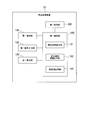
- FIG. 2 is a schematic block diagram illustrating an example of a functional configuration of the commodity monitoring device 13.
- the product monitoring device 13 includes a first communication unit 110, a first operation input unit 120, a first display unit 130, a first storage unit 180, and a first control unit 190.
- the first control unit 190 includes a product state detection unit 191, a change detection information output unit 192, and a moving image processing unit 193.
- the first communication unit 110 communicates with other devices.
- the first communication unit 110 receives image data captured by the shelf monitoring camera 11 and the in-store monitoring camera 16.
- the first communication unit 110 transmits a request for sales information to the POS system 17 and receives the sales information transmitted by the POS system 17.
- the first communication unit 110 transmits change detection information to the terminal device 15.
- the first operation input unit 120 includes input devices such as a keyboard and a mouse and receives user operations.
- the first display unit 130 includes a front screen such as a liquid crystal panel, for example, and displays various images according to the control of the first control unit 190.
- the first storage unit 180 stores various data.
- the first storage unit 180 is configured using a storage device provided in the commodity monitoring apparatus 13.
- the first control unit 190 controls each unit of the product monitoring device 13 to perform various processes.
- the first control unit 190 is configured by a CPU (Central Processing Unit) provided in the commodity monitoring device 13 reading out and executing a program from the first storage unit 180.
- CPU Central Processing Unit
- the product state detection unit 191 detects the extraction of a quantity of products from the product group area that satisfies a predetermined condition based on the image information of the product group area set in the product shelf 910. Specifically, the product state detection unit 191 compares an image of the product shelf 910 taken by the shelf monitoring camera 11 with a past image for each product group area. When the ratio of the partial area in which the difference from the past image in the image area of the product group area is detected is equal to or larger than a predetermined threshold, the product state detection unit 191 satisfies the predetermined condition from the product group area. It is determined that a quantity of products has been removed. In order to reduce the possibility of false detection due to a temporary image change when a customer passes in front of a shelf, the past image to be compared is traced back a long time to some extent, for example, an image 3 seconds ago A past image may be used.
- the quantity satisfying the predetermined condition used for the determination criterion of the product state detection unit 191 indicates the area ratio
- the predetermined condition is, for example, that the area of the image of the extracted product in the image captured by the shelf monitoring camera 11 occupies a predetermined ratio or more of the area of the image of the product group area including the image of the product.
- the quantity satisfying the predetermined condition used for the determination criterion of the product state detection unit 191 is not limited to this example.
- the quantity that satisfies the predetermined condition may indicate the number of products that are equal to or greater than the predetermined value.
- the product state detection unit 191 calculates the number of products taken out based on the image information of the product group area, and determines whether or not the number of products taken out is a predetermined number or more. It may be.
- the predetermined threshold here is set to 50%, for example. However, the predetermined threshold is not limited to 50%. In addition, a different threshold may be set for each product group area. For example, the user may set a relatively small threshold value for an area of an expensive product. Thereby, the product state detection unit 191 detects the removal of an expensive product even when a relatively small number of products are taken out.
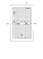
- FIG. 3 is a diagram illustrating an example of setting a product group area.
- a solid-line rectangle shown in FIG. 3 indicates a product group area.
- one or more product group areas are set in advance in the image of the product shelf 910 according to the arrangement of the products.
- the product state detection unit 191 determines whether or not a quantity of products satisfying a predetermined condition is taken out for each product group area shown in FIG.
- the standard for setting the product group area is not limited to a specific standard.
- a product group area may be set for each arrangement area of the same product, or a product group area may be set for each arrangement area of products of the same manufacturer.
- a product group area may be set for each arrangement area of the same type of product such as a magazine.
- a product group area may be set for each stage of the product shelf 910.
- the product group area may be set by a combination of a plurality of criteria. From the viewpoint of increasing the detection accuracy of the product state detection unit 191, it is preferable that the sizes of the products arranged in the same product group area are approximately the same.
- taking out a quantity of merchandise that satisfies a predetermined condition from the merchandise group area is also simply referred to as taking out.
- the change detection information output unit 192 includes time-series data of images of the product group area from the time when the product state detection unit 191 detects the removal to a predetermined past time when the product state detection unit 191 detects the removal.
- the change detection information is output to the terminal device 15.
- the first storage unit 180 stores images for the most recent predetermined period among images of the product shelf 910 taken by the shelf monitoring camera 11.
- image data for a predetermined period such as every 1 second among image data for a predetermined period such as the past 10 seconds from the time of detection of the removal is stored.
- the change detection information output unit 192 generates change detection information including the read image data.
- the change detection information output unit 192 transmits the generated change detection information to the terminal device 15 via the first communication unit 110.
- the change detection information output unit 192 acquires the sales information indicating the sales history of the product after the time when the product state detection unit 191 detects the removal from the POS system 17 via the first communication unit 110. Then, the change detection information output unit 192 outputs change detection information including the acquired sales information to the terminal device 15 via the first communication unit 110.
- a store clerk who refers to the terminal device 15 can determine whether or not the takeout is a legitimate takeout for purchase purpose by referring to the sales information. In other words, the store clerk determines whether or not the product has been purchased after the removal of the product is detected based on the sales information.
- the change detection information output unit 192 may output the acquired sales information to the terminal device 15 after outputting the change detection information to the terminal device 15. Specifically, the change detection information output unit 192 acquires, from the POS system 17, sales information indicating the sales history of the extracted product after the time when the product state detection unit 191 detects the extraction, and acquires the acquired sales information. Is output to the terminal device 15. Thus, the change detection information output unit 192 outputs change detection information to the terminal device 15 without waiting for the acquisition of sales information. Thereby, the salesclerk (user of the terminal device 15) possessing the terminal device 15 can quickly recognize and respond to the removal of the product from the product shelf 910.
- the change detection information output unit 192 may acquire the sales information registered in the POS system 17 within a predetermined time from the time when the product state detection unit 191 detects the takeout.
- the predetermined time in this case is also referred to as the first time.
- the sales information referred to by the store clerk who owns the terminal device 15 can be limited. In this respect, the load on the store clerk can be reduced.
- the change detection information output unit 192 includes the change detection information that does not include the sales information. May be output to the terminal device 15.
- the predetermined time in this case is also referred to as a second time.
- the first time and the second time may be the same time or different times.
- the second time may be set longer than the first time. If the first time is lengthened, it is considered that the number of sales information referred to by the store clerk who owns the terminal device 15 increases and the load on the store clerk increases. On the other hand, even if the second time becomes longer, the load on the store clerk does not increase. Therefore, the second time may be set to a relatively long time. Thereby, it is determined more accurately whether the product has been taken out of the store without being processed by the POS system 17.
- the change detection information output unit 192 may acquire information related to the person who has taken out the product based on the past image of the product group area based on the time when the product state detection unit 191 detected the takeout. Then, the change detection information output unit 192 may output change detection information including information about the person who has taken out the information to the terminal device 15. There is a high possibility that the person shown in the past image close to the point in time when the product state detection unit 191 detects the takeout is the person who took out the takeout. Therefore, the change detection information output unit 192 may detect a person reflected in the image of the shelf monitoring camera 11 retroactively from the time when the product state detection unit 191 detects the takeout.
- the change detection information output unit 192 goes back to the past in order from the image at the time when the product state detection unit 191 detects the removal, and detects the person until the person is successfully detected.
- the change detection information output unit 192 detects all the people appearing in the image within the past predetermined time (for example, 3 seconds) from the time when the product state detection unit 191 detects the removal. Also good. If the change detection information output unit 192 succeeds in detecting a person, the change detection information output unit 192 detects information about the person as information about a person who has taken out (a person who may have taken out).
- the change detection information output unit 192 determines, for example, the color of the person's clothes, includes the determined clothes color information in the change detection information, and outputs the change detection information to the terminal device 15.
- the information regarding the person who has taken out the information is not limited to the color information of the person's clothes, but can be various information.
- the change detection information output unit 192 may provide information about the person who has taken out, in addition to the information on the color of the person's clothes, or instead of the information on the color of the person's clothes, Information may be included in the change detection information.
- Other information regarding the person includes, for example, the face image of the person, flow line information indicating the movement of the person, information indicating whether the person has processed the product in the POS system 17, or the attribute information of the person Or a combination thereof.
- the attribute information of the person is either one or both of sex and height.
- the change detection information output unit 192 may output information about the person who has taken out the information to the terminal device 15 after outputting the change detection information to the terminal device 15. In this way, the change detection information output unit 192 outputs the change detection information to the terminal device 15 without waiting for the acquisition of information regarding the person who has taken out the change detection information. As a result, the store clerk possessing the terminal device 15 can quickly recognize and respond to the removal of the product from the product shelf 910.
- the change detection information output unit 192 may determine whether or not the person has passed the product through a predetermined clearing area based on information regarding the person who has taken out the change. Specifically, the change detection information output unit 192 may determine whether or not this person has settled the price in the POS system 17. When it is determined that the person does not pass the product to the checkout area, the change detection information output unit 192 outputs the change detection information to the terminal device 15 and then outputs information about the person who has taken out to the terminal device 15. You may make it do.
- the terminal device 15 provides information regarding the person who has taken out the change only when the change detection information output unit 192 determines that the person who has taken out the product has not passed the product through the predetermined clearing area. Output to.
- the change detection information output part 192 can reduce the frequency
- the moving image processing unit 193 displays a moving image of the product shelf 910 for a predetermined past time from when the product state detection unit 191 detects removal.
- the product monitoring device 13 including the first display unit 130 corresponds to an example of a display device.
- the shelf monitoring camera 11 captures a moving image of the product shelf 910 and transmits the moving image data to the product monitoring device 13.
- the moving image processing unit 193 temporarily stores the latest predetermined time among the past moving image data captured by the shelf monitoring camera 11 in the first storage unit 180.
- the moving image processing unit 193 starts from the time when the product state detection unit 191 detects the removal of the moving image data temporarily stored in the first storage unit 180.
- the moving image data for a predetermined past time is stored in the first storage unit 180.
- the first storage unit 180 stores the moving image data instructed to be saved by the moving image processing unit 193 without erasing it.
- the moving image processing unit 193 reproduces moving image data in accordance with a user operation and displays it on the first display unit 130.
- the merchandise monitoring device 13 displays a moving image of the merchandise shelf 910
- the terminal device 15 displays a frame advance image (a still image for every predetermined time) of the merchandise shelf 910. In this way, images can be used properly according to the communication bandwidth and the processing capability of the apparatus.
- the terminal device 15 may display a moving image of the product shelf 910.
- the terminal device 15 When the terminal device 15 receives the change detection information from the product monitoring device 13, the terminal device 15 outputs a take-out warning (alarm).
- the take-out alarm here is an alarm indicating that the take-out has been performed.
- the terminal device 15 corresponds to an example of an output destination device. Further, the terminal device 15 generates and updates the damage information according to the user operation.
- the damage information here is information indicating whether or not the extraction is illegal and the status of the extraction.
- the terminal device 15 is configured using a portable terminal device such as a tablet terminal device or a smartphone.
- the terminal device 15 may be configured as a fixed terminal device.
- the terminal device 15 is fixedly installed near the POS system 17.
- a store clerk in the sales floor has the terminal device 15.
- the store clerk confirms the status of the product shelf 910.
- the store clerk confirms the situation near the merchandise shelf 910, calls out to the customer, performs work near the customer, reports to the security guard, and the like as necessary. This may prevent theft in advance. Further, the store clerk inputs damage information to the terminal device 15 based on the confirmation result of the status of the product shelf 910.
- FIG. 4 is a schematic block diagram illustrating a functional configuration example of the terminal device 15.
- the terminal device 15 includes a second communication unit 210, a second operation input unit 220, a second display unit 230, a second storage unit 280, and a second control unit 290.
- the second control unit 290 includes a change detection information acquisition unit 291 and a damage information processing unit 292.
- the second communication unit 210 communicates with other devices.
- the second communication unit 210 receives change detection information from the product monitoring device 13.
- the second communication unit 210 transmits the damage information to the product monitoring device 13.
- the second display unit 230 includes a display screen such as a liquid crystal panel, and displays various images according to the control of the second control unit 290.
- the second display unit 230 displays any one of the time-series data of the images included in the change detection information based on a user operation according to the control of the second control unit 290.
- the change detection information includes an image at every predetermined time among images obtained by photographing the product shelf 910 by the shelf monitoring camera 11.
- the second display unit 230 displays an image designated by the user operation among the images of the product shelf 910 included in the change detection information according to the control of the second control unit 290.
- the second operation input unit 220 includes, for example, a touch sensor that is provided on the display screen of the second display unit 230 and forms a touch panel, and receives a user operation.
- the second storage unit 280 stores various data.
- the second storage unit 280 is configured using a storage device provided in the terminal device 15.
- the second control unit 290 performs various processes by controlling each unit of the terminal device 15.
- the second control unit 290 is configured by a CPU included in the terminal device 15 reading out and executing a program from the second storage unit 280.
- the change detection information acquisition unit 291 acquires change detection information from the product monitoring device 13. Specifically, when the product monitoring device 13 detects removal and transmits change detection information, the second communication unit 210 receives communication data from the product monitoring device 13. The change detection information acquisition unit 291 extracts change detection information from the communication data received by the second communication unit 210. The change detection information acquisition unit 291 displays a take-out alarm on the second display unit 230 based on the change detection information. The terminal device 15 may output the take-out alarm by either one or both of voice and vibration in addition to the display of the second display unit 230 or instead of the display of the second display unit 230. .
- the damage information processing unit 292 generates and updates damage information according to user operations. Specifically, the damage information processing unit 292 causes the second display unit 230 to display a detailed registration screen for editing damage information, triggered by reception of change detection information or a user operation (trigger). And if the salesclerk who is a user of terminal device 15 performs user operation which inputs damage information according to a detailed registration screen, damage information processing part 292 will generate or update damage information according to user operation.
- the hub 12 mediates communication between devices connected to the hub 12.
- the hub 12 is provided between the shelf monitoring camera 11 and the product monitoring device 13, between the in-store monitoring camera 16 and the product monitoring device 13, between the POS system 17 and the product monitoring device 13, and between the wireless router device 14 and the product.
- Each communication path is established with the monitoring device 13.
- the wireless router device 14 performs wireless communication with the terminal device 15 and mediates communication between the terminal device 15 and each device.
- a communication path between the product monitoring device 13 and the terminal device 15 is established by a combination of the hub 12 and the wireless router device 14.
- the configuration of the commodity monitoring system 10 is not limited to the configuration shown in FIG.
- the terminal device 15 may also have the function of the product monitoring device 13.
- the product monitoring system 10 may not include the product monitoring device 13.
- the in-store monitoring camera 16 and the POS system 17 are not essential for the product monitoring system 10.
- the product monitoring system 10 may not include any one or both of the in-store monitoring camera 16 and the POS system 17.
- the merchandise monitoring apparatus 13 may directly communicate with other devices.
- the product monitoring system 10 may not include any one or both of the hub 12 and the wireless router device 14.
- FIG. 5 is a diagram illustrating an example of a notification screen displayed by the second display unit 230.
- the display of the notification screen by the second display unit 230 corresponds to an example of output of a take-out alarm.
- the second display unit 230 displays a product group area where the removal has been detected, and displays a message indicating that the removal has been detected. Further, the second display unit 230 displays push button icons in the areas A111 and A112, respectively.
- the second display unit 230 When the touch operation is performed on the area A111, the second display unit 230 ends the display of the take-out alarm according to the control of the second control unit 290, and displays a standby screen (desktop screen). When the touch operation on the area A112 is performed, the second display unit 230 displays the detection information screen according to the control of the second control unit 290.
- the detection information screen will be described with reference to FIG.
- FIG. 6 is a diagram illustrating an example of a detection information screen displayed by the second display unit 230.
- the second display unit 230 displays an image of the product shelf 910 captured by the shelf monitoring camera 11 in the area A211.
- a region A212 in the image of the product shelf 910 is a region where the product state detection unit 191 has detected a change in the image.
- the second display unit 230 indicates an area in which an image change is detected in the image of the product shelf 910.
- the image displayed on the area A211 by the second display unit 230 is one image among a plurality of time-series images from the time when the product state detection unit 191 detects take-out to a predetermined past time.
- the second display unit 230 switches images according to user operations.
- the second display unit 230 displays an image at a later time point according to the control of the second control unit 290.
- the second display unit 230 displays the image at the previous time point according to the control of the second control unit 290.
- the second display unit 230 indicates the shooting time information of the image displayed in the area A211 in the area A221.
- the second display unit 230 switches the image displayed in the area A211 to the image at the time when the product state detection unit 191 detects the take-out according to the second control unit 290.
- the second display unit 230 displays a push button icon in each of the display areas A231 and A232.
- the second display unit 230 displays a detailed registration screen according to the control of the second control unit 290. The detailed registration screen will be described later with reference to FIG.
- the second display unit 230 displays a standby screen. In this case, it means that the store clerk who is the user of the terminal device 15 determines that the removal is a valid removal. Therefore, the terminal device 15 ends the screen display relating to the extraction without requesting the user to input detailed information regarding the extraction.
- the second display unit 230 displays the time when the product state detection unit 191 detects the takeout in the region A241, and displays the name of the product group area where the product state detection unit 191 detects the takeout in the region A242. .
- the name of the product group area is set in advance by the user, for example.
- FIG. 7 is a diagram illustrating a first example of a detail registration screen displayed by the second display unit 230.
- the areas A311, A321, and A322 are the same as the areas A211, A221, and A222 of FIG.
- Regions A331 and A332 are the same as regions A241 and A242 in FIG. 6, respectively.
- the second display unit 230 displays status information in the area A333.
- This situation information is information indicating a determination result in which a store clerk who is a user of the terminal device 15 determines whether or not there is a problem with taking out.
- the value of the status information is set to “problem” by the touch operation on the area A231 in FIG.
- the value of the status information is set to “no problem” by a touch operation on the area A232 in FIG.
- the user can change the value of the situation information.
- the second display unit 230 displays pull-down menus indicating “problem” and “no problem”.
- the damage information processing unit 292 updates the value of the situation information to the value selected by the touch operation.
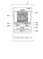
- FIG. 8 is a diagram illustrating a second example of the detail registration screen displayed by the second display unit 230.
- FIG. 8 shows an example of a detail registration screen continued in the downward direction of the detail registration screen shown in FIG.
- the second display unit 230 displays the screen of FIG. 8 according to the control of the damage information processing unit 292 by scrolling down the detail registration screen of FIG.
- a region A334 is an input field in which information regarding the damaged product can be input.
- the second operation input unit 220 receives a product name and quantity input of a product that has been stolen (a product taken out from the product shelf 910) by free word input.
- Area A335 is an input column for the total damage amount.
- the second operation input unit 220 accepts an input of the total amount of damage (for example, the total amount of theft damage) by taking out the target by free word input.
- An area A336 is a comment input field. The second operation input unit 220 receives a user's comment by free word input.
- Area A337 is a display field for the registrant.
- the second operation input unit 220 may accept an input operation for a registrant name. Alternatively, the second operation input unit 220 may cause the damage information processing unit 292 to automatically display in the area A337 the name of the user who has logged into the terminal device 15 when the damage information is input.
- the damage information processing unit 292 transmits the input damage information to the product monitoring device 13 via the second communication unit 210.
- the first storage unit 180 stores the damage information in association with the change detection information.
- the second display unit 230 ends the display of the detailed registration screen, and displays, for example, a damage information list screen.
- the damage information list screen will be described with reference to FIG.
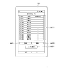
- FIG. 9 is a diagram illustrating an example of a damage information list screen displayed by the second display unit 230.
- the second display unit 230 displays a list of damage information in the area A411.
- An area A421 is a touch area that receives an update of damage information.
- the damage information processing unit 292 receives the selected damage information from the commodity monitoring device 13. get. Then, the damage information processing unit 292 causes the second display unit 230 to display a detailed registration screen having the acquired damage information.
- the damage information processing unit 292 updates the damage information according to the information updated according to the user operation.
- Area A422 is a touch area that accepts deletion of damage information.
- the damage information processing unit 292 issues an instruction to delete the selected damage information.
- the information is transmitted to the commodity monitoring apparatus 13 via the communication unit 110.
- the merchandise monitoring apparatus 13 deletes the damage information in accordance with the deletion instruction.
- An area A431 is a touch area that receives a display end instruction related to removal.
- the second display unit 230 ends the display relating to the extraction and displays a standby screen according to the control of the second control unit 290.
- FIG. 10 is a diagram illustrating an example of a sales history screen displayed by the second display unit 230.
- the product monitoring device 13 acquires the sales information from the POS system 17 and associates the change detection information with the sales information to the first storage unit 180.
- various correspondence relationships can be adopted as the correspondence relationship between the retrieval and the sales information.
- the merchandise monitoring device 13 may determine sales information within a predetermined time after taking out as sales information corresponding to the taking out.
- the product monitoring device 13 determines the sales information indicating the purchase of the product taken out from the product shelf 910 out of the sales information within a predetermined time as the sales information corresponding to this take-out. May be.
- the damage information processing unit 292 displays the detection information screen.
- the sales information associated with is displayed on the second display unit 230.
- the damage information processing unit 292 acquires the sales information associated with the retrieval that is the target on the currently displayed detection information screen from the product monitoring device 13 and causes the second display unit 230 to display the sales information.
- a user operation for instructing display of the sales history screen (FIG. 10) is performed while the second display unit 230 is displaying the detailed registration screen (FIGS. 7 and 8)
- the damage information processing unit 292 The sales information associated with the detailed registration screen is displayed on the second display unit 230.
- the damage information processing unit 292 acquires the sales information associated with the retrieval that is the target on the detailed registration screen being displayed from the product monitoring device 13 and causes the second display unit 230 to display the sales information.
- the second display unit 230 ends the display of the sales history screen and displays the detection information screen (FIG. 6) or the detailed registration screen (FIG. 7, FIG. 7).
- FIG. 11 is a diagram illustrating an example of a flow line screen displayed by the second display unit 230.
- the second display unit 230 displays the flow line information of the customer who has taken out the information on the floor plan of the store.
- the customer has stopped at the counter.
- the counter corresponds to an example of a predetermined settlement area.
- the second display unit 230 displays the time when the customer stopped at the counter in addition to the customer flow line information.
- a store clerk who is a user of the terminal device 15 causes the terminal device 15 to display sales information at a timing when the customer stops at the counter. Thereby, it is possible to determine whether or not the extraction is a valid extraction.
- the sales information at the timing when the customer stops at the counter indicates that the product to be taken out has been purchased, it can be determined that the takeout was a valid takeout.
- the 2nd display part 230 displays the information which shows whether the customer who took out paid with the counter instead of the flow line information or in addition to the flow line information by a character or a symbol. May be.
- the character indicating whether or not payment has been made is, for example, “payment present” / “no payment”.
- the symbol indicating whether or not payment has been made is, for example, “Maru” / “X”.
- FIG. 12 is a diagram illustrating an example of the operation of the commodity monitoring system 10 when the removal is detected.
- the shelf monitoring camera 11 transmits the image data generated by photographing the product shelf 910 to the product monitoring device 13 (sequence S101).
- the shelf monitoring camera 11 may continuously transmit the moving image data of the product shelf 910 to the product monitoring device 13.
- the shelf monitoring camera 11 may collectively transmit the moving image data of the product shelf 910 to the product monitoring device 13 every predetermined time.
- the shelf monitoring camera 11 may transmit still image data corresponding to a frame of moving image data to the commodity monitoring device 13 instead of transmitting moving image data.
- the merchandise monitoring apparatus 13 that has acquired the image data of the merchandise shelf 910 determines the presence / absence of removal based on the obtained image data (sequence S102). Specifically, the product monitoring device 13 compares the newly acquired image of the product shelf 910 with the past image of the product shelf 910, and detects the difference between the images. The merchandise monitoring apparatus 13 determines whether the ratio of the partial area corresponding to the detected difference to the total area of the merchandise group area is greater than or equal to the threshold for any merchandise group area. When it determines with a ratio being more than a threshold value, the goods monitoring apparatus 13 determines with taking out. In the example of FIG. 12, the product monitoring device 13 determines that there is a takeout.
- the product monitoring apparatus 13 that has determined that there is a removal generates change detection information regarding the detected removal and transmits it to the terminal device 15 (sequence S103).
- the terminal device 15 outputs a take-out alarm based on the change detection information received from the product monitoring device 13 (sequence S104).
- the merchandise monitoring apparatus 13 saves (stores) the generated change detection information (sequence S105).
- the merchandise monitoring device 13 may generate change detection information including one or both of sales information and flow line information. Alternatively, after the product monitoring device 13 transmits the change detection information to the terminal device 15, either or both of the sales information and the flow line information may be transmitted to the terminal device 15.
- FIG. 13 is a flowchart illustrating an example of a processing procedure in which the product monitoring device 13 determines whether or not a product is taken out.
- the product state detection unit 191 acquires image data of the product shelf 910 from the shelf monitoring camera 11 via the first communication unit 110 (step S201). Then, the product state detection unit 191 compares the image data of the product shelf 910 obtained in step S201 with the past image data (for example, an image 10 seconds before) of the product shelf 910 (step S202).
- the product state detection unit 191 determines whether or not the ratio of the area of the difference (difference) in the image of the product group area to the area of the entire product group area is greater than or equal to the threshold (step S203). ).
- step S203 When it determines with a ratio being less than a threshold value about any merchandise group area (step S203: NO), it returns to step S201.
- the goods monitoring apparatus 13 performs the process at the time of taking-out detection (step S204). For example, as described with reference to FIG. 12, the product monitoring device 13 generates change detection information and transmits the change detection information to the terminal device 15, and stores the generated change detection information. After step S204, the process returns to step S201.
- the product state detection unit 191 detects the removal of a quantity of products satisfying a predetermined condition from the product group area based on the image information of the product group area set in the product shelf 910.
- the change detection information output unit 192 when the product state detection unit 191 detects take-out, changes detection information including time-series data of images of the product group area from the time when the take-out is detected to a predetermined past time, Output to the terminal device 15.
- the store clerk who is the user of the terminal device 15 can recognize the possibility of unauthorized removal by recognizing the removal based on the change detection information. For example, when the terminal device 15 outputs a take-out alarm based on the change detection information, the store clerk can recognize the take-out.
- the merchandise monitoring system 10 can detect the possibility of unauthorized removal with a relatively simple configuration in which the merchandise shelf 910 is photographed by the shelf monitoring camera 11.
- the product monitoring system 10 it is possible to detect an event that the product is expected to be taken out of the store illegally at a relatively low cost.
- the change detection information output unit 192 may acquire sales information after the point in time when the product state detection unit 191 detects take-out, and output the change detection information including the sales information to the terminal device 15. Thereby, the salesclerk who is the user of the terminal device 15 can determine whether or not the takeout is a valid takeout with reference to the change detection information.
- the change detection information output unit 192 After the change detection information output unit 192 outputs the change detection information to the terminal device 15, the change detection information output unit 192 acquires sales information after the time when the product state detection unit 191 detects the takeout and outputs the sales information to the terminal device 15. Good. The user of the terminal device 15 can determine whether or not the extraction is valid by referring to the sales information. Further, the change detection information output unit 192 outputs the change detection information to the terminal device 15 without waiting for the acquisition of sales information. For this reason, the user of the terminal device 15 can quickly recognize and respond to the removal of the product from the product shelf 910.
- the change detection information output unit 192 may acquire the sales information registered in the POS system 17 within a predetermined time from the time when the product state detection unit 191 detects the removal. Thus, the change detection information output unit 192 limits the time range for acquiring sales information. Thereby, the sales information referred to by the store clerk possessing the terminal device 15 can be limited. In this respect, the load on the store clerk can be reduced.
- the change detection information output unit 192 cannot acquire the sales information related to the extracted product from the POS system 17 within a predetermined time from the time when the product state detection unit 191 detects the extraction, the sales information is included. No change detection information may be output to the terminal device 15. If the sales clerk who owns the terminal device 15 does not include sales information in the change detection information, it can be estimated that there is a high possibility that the corresponding product has been taken out of the store without going through the POS system 17. That is, the store clerk can estimate that there is a high possibility that the corresponding product has been stolen.
- the change detection information output unit 192 acquires information about the person who has taken out the product based on the past image of the product group area based on the time when the product state detection unit 191 detects the takeout, and outputs the information to the terminal device 15. You may make it do.
- the user of the terminal device 15 specifies the person who has taken out, the user identification accuracy can be improved by referring to the information regarding the person who has taken out the person.
- the change detection information output unit 192 detects information about the person who has taken out the product based on the past images of the product group area based on the time when the product state detection unit 191 detects the takeout. At this time, the change detection information output unit 192 may output the change detection information to the terminal device 15 and then output information related to the extracted person to the terminal device 15. When the user of the terminal device 15 specifies the person who has taken out, the user can improve the specific accuracy by referring to the information regarding the person who has taken out the person. Further, the change detection information output unit 192 outputs the change detection information to the terminal device 15 without waiting for acquisition of information regarding the person who has taken out. Accordingly, the user of the terminal device 15 can quickly recognize and respond to the removal of the product from the product shelf 910.
- the change detection information output unit 192 may determine whether or not the person has passed the product (the product that has been taken out) through a predetermined clearing area based on information about the person who has taken out the information. When it is determined that the information has not been passed, the change detection information output unit 192 may output the change detection information to the terminal device 15 and then output information about the person who has taken out the information to the terminal device 15. In this way, the change detection information output unit 192 determines whether or not the person who has taken out has passed the taken-out product through the checkout area. Thereby, the user of the terminal device 15 can be used as reference information when determining whether or not the extraction is valid.
- the second display unit 230 of the terminal device 15 may display any one of the time-series data of the images included in the change detection information based on a user operation.
- the user of the terminal device 15 can grasp the situation when the extraction is performed with reference to the image displayed by the second display unit 230.
- the first display unit 130 of the product monitoring device 13 may display a moving image of the product group area from the time when the product state detection unit 191 detects the takeout to a predetermined past time.
- the user of the product monitoring device 13 can grasp the situation when the product is taken out with reference to the moving image.
- FIG. 14 is a diagram illustrating an example of the minimum configuration of the commodity monitoring apparatus according to the present embodiment.
- the product monitoring apparatus 20 illustrated in FIG. 14 includes a product state detection unit 21 and a change detection information output unit 22.
- the product state detection unit 21 detects the removal of a quantity of products that satisfy a predetermined condition from the product group area based on the image information of the product group area set in the product shelf.
- the change detection information output unit 22 includes time-series data of images of the product group area from the time when the product state detection unit 21 detects the take-out to a predetermined past time when the product state detection unit 21 detects the take-out. Outputs change detection information to the output destination device.
- the user can recognize the possibility of unauthorized extraction by recognizing the extraction based on the change detection information.
- the merchandise monitoring apparatus 20 can detect the possibility of unauthorized removal with a relatively simple configuration in which a merchandise shelf is photographed with a camera.
- an event that an unauthorized product is expected to be taken out of the store can be detected at a relatively low cost.
- FIG. 15 is a diagram illustrating an example of the minimum configuration of the commodity monitoring system according to the present embodiment.
- the product monitoring system 30 illustrated in FIG. 15 includes a product monitoring device 31 and an output destination device 34.
- the product monitoring device 31 includes a product state detection unit 32 and a change detection information output unit 33.
- the product state detection unit 32 detects the removal of a quantity of products that satisfy a predetermined condition from the product group area based on the image information of the product group area set in the product shelf.
- the change detection information output unit 33 includes time-series data of images of the product group area from the time when the product state detection unit 32 detects the removal to a predetermined past time when the product state detection unit 32 detects the removal.
- the change detection information is output to the output destination device 34.
- the user can recognize the possibility of unauthorized extraction by recognizing the extraction based on the change detection information.
- the merchandise monitoring system 30 can detect the possibility of unauthorized removal with a relatively simple configuration in which a merchandise shelf is photographed with a camera.
- the product monitoring system 30 can detect an event that a product is expected to be taken out of the store illegally at a relatively low cost.
- FIG. 16 is a diagram illustrating an example of the minimum configuration of the output destination apparatus according to the present embodiment.
- the output destination device 40 illustrated in FIG. 16 includes a change detection information acquisition unit 41 and a display unit 42.
- the change detection information acquisition unit 41 detects the removal of a quantity of products satisfying a predetermined condition from the product group area set in the product shelf
- the change detection information acquisition unit 41 performs a predetermined past time from when the removal is detected.
- Change detection information including time-series data of images of the product group area up to is acquired.
- the display unit 42 displays an image of the product group area included in the change detection information. The user can grasp the situation when the product is taken out by referring to the image of the product group area.
- a program for realizing all or part of the functions of the first control unit 190 and the second control unit 290 is recorded on a computer-readable recording medium, and the program recorded on the recording medium is stored in a computer system. Processing may be performed by reading and executing.
- the “computer system” includes an OS and hardware such as peripheral devices.
- the “computer-readable recording medium” refers to a storage device such as a flexible medium, a magneto-optical disk, a portable medium such as a ROM or a CD-ROM, and a hard disk incorporated in a computer system.
- the program may be a program for realizing a part of the functions described above, and may be a program capable of realizing the functions described above in combination with a program already recorded in a computer system.
- a product condition detection unit Based on the image information of the product group area set in the product shelf, a product condition detection unit that detects the removal of a quantity of products from the product group area that satisfies a predetermined condition; When the product state detection unit detects the takeout, it outputs change detection information including time series data of images of the product group area from the time when the product state detection unit detects the takeout to a predetermined past time point.
- a change detection information output unit for output to the destination device;
- a product monitoring device comprising:
- the change detection information output unit acquires sales information indicating a sales history of the product after a time point when the product state detection unit detects the takeout, and outputs the change detection information including the sales information.
- the change detection information output unit acquires sales information indicating a sales history of the product at a time point after the time when the product state detection unit detects the takeout after outputting the change detection information to the output destination device.
- the merchandise monitoring apparatus according to claim 1, wherein the sales information is output to the output destination apparatus.
- the change detection information output unit acquires information on a person who has taken out the product based on a past image of the product group area based on a time point when the product state detection unit detects the takeout, and the product
- the product monitoring device according to any one of appendices 1 to 5, wherein information relating to the person who has taken out the information is output to the output destination device.
- the change detection information output unit detects information about a person who has taken out the product based on a past image of the product group area based on a time point when the product state detection unit detects the takeout, and the change The product monitoring device according to any one of appendices 1 to 5, wherein after the detection information is output to the output destination device, the information related to the person is output to the output destination device.
- the change detection information output unit determines whether the person has passed the product through a predetermined clearing area based on information about the person who has taken out the product.
- the product monitoring apparatus according to appendix 7, wherein information relating to a person is output to the output destination apparatus.
- a product monitoring system comprising a product monitoring device and an output destination device,
- the commodity monitoring apparatus is Based on the image information of the product group area set in the product shelf, a product condition detection unit that detects the removal of a quantity of products from the product group area that satisfies a predetermined condition;
- the change detection information including time-series data of images of the product group area from the time when the product state detection unit detects the take-out to a predetermined past time point.
- a change detection information output unit to output to the output destination device;
- the output destination device is: The product monitoring system according to claim 9, further comprising a display unit configured to display any one of the time-series data of the images included in the change detection information based on a user operation.
- appendix 11 The product monitoring system according to appendix 9 or appendix 10, further comprising a display device that displays a moving image of the product group area from a time point when the product state detection unit detects the takeout to a predetermined past time point.
- a change detection information acquisition unit for acquiring change detection information including series data
- An output destination device comprising: a display unit configured to display the image of the product group area included in the change detection information.
- a product monitoring method comprising: outputting change detection information including time-series data of images of the product group area to an output destination device.
Landscapes
- Business, Economics & Management (AREA)
- Engineering & Computer Science (AREA)
- Accounting & Taxation (AREA)
- Physics & Mathematics (AREA)
- General Physics & Mathematics (AREA)
- Finance (AREA)
- Theoretical Computer Science (AREA)
- General Business, Economics & Management (AREA)
- Strategic Management (AREA)
- Economics (AREA)
- Signal Processing (AREA)
- Computer Networks & Wireless Communication (AREA)
- Marketing (AREA)
- Development Economics (AREA)
- Human Resources & Organizations (AREA)
- Operations Research (AREA)
- Quality & Reliability (AREA)
- Computer Vision & Pattern Recognition (AREA)
- Tourism & Hospitality (AREA)
- Entrepreneurship & Innovation (AREA)
- Multimedia (AREA)
- Management, Administration, Business Operations System, And Electronic Commerce (AREA)
- Closed-Circuit Television Systems (AREA)
Abstract
A commodity monitoring device provided with: a commodity state detection unit that, on the basis of image information of a commodity group area set on a commodity shelf, detects withdrawal of commodities in quantities satisfying a predetermined condition from the commodity group area; and a change sensing information output unit that, if the commodity state detection unit has detected the withdrawal, outputs, to an output destination device, change sensing information including time-series data of an image of the commodity group area from a point in time at which the commodity state detection unit detected the withdrawal to a predetermined past point in time.
Description
本発明は、商品監視装置、商品監視システム、出力先装置、商品監視方法、表示方法及びプログラムに関する。
The present invention relates to a product monitoring device, a product monitoring system, an output destination device, a product monitoring method, a display method, and a program.
商品棚に置かれた商品の管理に関連して幾つかの技術が提案されている。
例えば、特許文献1に記載の在庫状況管理方法では、商品の陳列棚(商品棚)の画像を監視し、陳列棚に設けられた商品無マーカを検知したときに、その商品無マーカに関連付けられた該当商品を割り出す。そして、商品無マーカが検知された陳列棚の画像の位置に在庫確認中である旨のメッセージを重ねる処理が行われる。 Several techniques have been proposed in connection with the management of products placed on product shelves.
For example, in the inventory status management method described inPatent Literature 1, when an image of a product display shelf (product shelf) is monitored and a product-free marker provided on the display shelf is detected, it is associated with the product-free marker. Find the appropriate product. Then, a process of superimposing a message indicating that the inventory is being confirmed is performed at the position of the image on the display shelf where the product no marker is detected.
例えば、特許文献1に記載の在庫状況管理方法では、商品の陳列棚(商品棚)の画像を監視し、陳列棚に設けられた商品無マーカを検知したときに、その商品無マーカに関連付けられた該当商品を割り出す。そして、商品無マーカが検知された陳列棚の画像の位置に在庫確認中である旨のメッセージを重ねる処理が行われる。 Several techniques have been proposed in connection with the management of products placed on product shelves.
For example, in the inventory status management method described in
商品を販売する店舗において、商品の不正な店外への持ち出しが予想される事象を、なるべく低コストで検出できることが好ましい。これに対し、特許文献1には、商品の不正な店外への持ち出しが予想される事象を検出する方法は示されていない。
It is preferable that an event in which a product is expected to be taken out of the store illegally can be detected at a cost as low as possible in a store that sells the product. On the other hand, Patent Document 1 does not disclose a method for detecting an event that an item is expected to be taken out of the store illegally.
本発明は、上述の課題を解決することのできる商品監視装置、商品監視システム、出力先装置、商品監視方法、表示方法及びプログラムを提供することを目的としている。
The object of the present invention is to provide a product monitoring device, a product monitoring system, an output destination device, a product monitoring method, a display method, and a program that can solve the above-described problems.
本発明の第1の態様によれば、商品監視装置は、商品棚に設定された商品群エリアの画像情報に基づいて、所定条件を満たす、前記商品群エリアからの数量の商品の取出しを検出する商品状態検出部と、前記商品状態検出部が前記取出しを検出した場合、前記商品状態検出部が前記取出しを検出した時点から所定の過去の時点までの前記商品群エリアの画像の時系列データを含む変化検知情報を出力先装置へ出力する変化検知情報出力部と、を備える。
According to the first aspect of the present invention, the merchandise monitoring apparatus detects the removal of a quantity of merchandise from the merchandise group area that satisfies a predetermined condition based on image information of the merchandise group area set in the merchandise shelf. When the product state detection unit detects the takeout and the product state detection unit detects the takeout, the time series data of the image of the product group area from the time when the product state detection unit detects the takeout to a predetermined past time point A change detection information output unit that outputs change detection information including the information to the output destination device.
本発明の第2の態様によれば、商品監視システムは、商品監視装置と出力先装置とを備えた商品監視システムであって、前記商品監視装置は、商品棚に設定された商品群エリアの画像情報に基づいて、所定条件を満たす、前記商品群エリアからの数量の商品の取出しを検出する商品状態検出部と、前記商品状態検出部が前記取出しを検出した場合、前記商品状態検出部が前記取出しを検出した時点から所定の過去の時点までの前記商品群エリアの画像の時系列データを含む変化検知情報を前記出力先装置へ出力する変化検知情報出力部と、を備える。
According to the second aspect of the present invention, the product monitoring system is a product monitoring system comprising a product monitoring device and an output destination device, wherein the product monitoring device is a product group area set in a product shelf. Based on the image information, a product state detection unit that detects the removal of a quantity of products from the product group area that satisfies a predetermined condition, and when the product state detection unit detects the removal, the product state detection unit A change detection information output unit that outputs change detection information including time-series data of images of the product group area from the time when the take-out is detected to a predetermined past time to the output destination device.
本発明の第3の態様によれば、出力先装置は、所定条件を満たす、商品棚に設定された商品群エリアからの数量の商品の取出しが検出された場合、前記取出しが検出された時点から所定の過去の時点までの前記商品群エリアの画像の時系列データを含む変化検知情報を取得する変化検知情報取得部と、前記変化検知情報に含まれる前記商品群エリアの前記画像を表示する表示部とを備える。
According to the third aspect of the present invention, when the output destination device detects the removal of a quantity of products from the product group area set in the product shelf that satisfies the predetermined condition, the output destination is detected. A change detection information acquiring unit for acquiring change detection information including time-series data of images of the product group area from a predetermined past time point, and displaying the image of the product group area included in the change detection information A display unit.
本発明の第4の態様によれば、商品監視方法は、商品棚に設定された商品群エリアの画像情報に基づいて、所定条件を満たす、前記商品群エリアからの数量の商品の取出しを検出した場合、前記取出しを検出した時点から所定の過去の時点までの前記商品群エリアの画像の時系列データを含む変化検知情報を出力先装置へ出力することを含む。
According to the fourth aspect of the present invention, the merchandise monitoring method detects the removal of a quantity of merchandise from the merchandise group area that satisfies a predetermined condition based on image information of the merchandise group area set in the merchandise shelf. In this case, it includes outputting change detection information including time-series data of images of the product group area from the time when the take-out is detected to a predetermined past time to the output destination device.
本発明の第5の態様によれば、表示方法は、所定条件を満たす、商品棚に設定された商品群エリアからの数量の商品の取出しが検出された場合、前記取出しが検出された時点から所定の過去の時点までの前記商品群エリアの画像の時系列データを含む変化検知情報を取得し、前記変化検知情報に含まれる前記商品群エリアの前記画像を表示することを含む。
According to the fifth aspect of the present invention, when the removal of a quantity of products from the product group area set in the product shelf satisfying the predetermined condition is detected, the display method starts from the time when the take-out is detected. Obtaining change detection information including time-series data of images of the product group area up to a predetermined past time point, and displaying the image of the product group area included in the change detection information.
本発明の第6の態様によれば、プログラムは、コンピュータに、商品棚に設定された商品群エリアの画像情報に基づいて、所定条件を満たす、前記商品群エリアからの数量の商品の取出しを検出した場合、前記取出しを検出した時点から所定の過去の時点までの前記商品群エリアの画像の時系列データを含む変化検知情報を出力先装置へ出力させる処理を実行させる。
According to the sixth aspect of the present invention, the program causes the computer to take out a quantity of products from the product group area that satisfies a predetermined condition based on the image information of the product group area set in the product shelf. If detected, a process for causing the output destination device to output change detection information including time-series data of images of the product group area from the time when the take-out is detected to a predetermined past time is executed.
本発明の第7の態様によれば、プログラムは、コンピュータに、所定条件を満たす、商品棚に設定された商品群エリアからの数量の商品の取出しが検出された場合、前記取出しが検出された時点から所定の過去の時点までの前記商品群エリアの画像の時系列データを含む変化検知情報を取得させ、前記変化検知情報に含まれる前記商品群エリアの前記画像を表示させる処理を実行させる。
According to the seventh aspect of the present invention, the program detects the take-out when the take-out of the quantity of the product from the product group area set in the product shelf satisfying the predetermined condition is detected in the computer. Change detection information including time-series data of images of the product group area from a time point to a predetermined past time point is acquired, and a process of displaying the image of the product group area included in the change detection information is executed.
この発明によれば、商品の不正な店外への持ち出しが予想される事象を、比較的低コストで検出することができる。
According to the present invention, it is possible to detect an event that an illegal product is expected to be taken out of the store at a relatively low cost.
以下、本発明の実施形態を説明するが、以下の実施形態は請求の範囲にかかる発明を限定するものではない。また、実施形態の中で説明されている特徴の組み合わせの全てが発明の解決手段に必須であるとは限らない。
図1は、一実施形態に係る商品監視システムの装置構成例を示す概略構成図である。図1の例で、商品監視システム10は、棚監視カメラ11と、ハブ12と、商品監視装置13と、無線ルータ装置14と、端末装置15と、店内監視カメラ16と、POS(Point Of Sales)システム17とを備える。 Hereinafter, although embodiment of this invention is described, the following embodiment does not limit the invention concerning a claim. In addition, not all the combinations of features described in the embodiments are essential for the solving means of the invention.
FIG. 1 is a schematic configuration diagram illustrating a device configuration example of a product monitoring system according to an embodiment. In the example of FIG. 1, theproduct monitoring system 10 includes a shelf monitoring camera 11, a hub 12, a product monitoring device 13, a wireless router device 14, a terminal device 15, an in-store monitoring camera 16, and a POS (Point Of Sales). ) System 17.
図1は、一実施形態に係る商品監視システムの装置構成例を示す概略構成図である。図1の例で、商品監視システム10は、棚監視カメラ11と、ハブ12と、商品監視装置13と、無線ルータ装置14と、端末装置15と、店内監視カメラ16と、POS(Point Of Sales)システム17とを備える。 Hereinafter, although embodiment of this invention is described, the following embodiment does not limit the invention concerning a claim. In addition, not all the combinations of features described in the embodiments are essential for the solving means of the invention.
FIG. 1 is a schematic configuration diagram illustrating a device configuration example of a product monitoring system according to an embodiment. In the example of FIG. 1, the
また、図1には、商品監視システム10が監視する対象の商品が陳列される商品棚910が示されている。商品監視システム10が対象とする商品棚910は1つであってもよいし複数あってもよい。
また、図1の例では、棚監視カメラ11と、端末装置15と、店内監視カメラ16と、POSシステム17と、商品棚910とが売場に配置されている。ハブ12と、商品監視装置13と、無線ルータ装置14とがバックルームに配置されている。バックルームは、基本的には顧客の立ち入りが禁止されている部屋である。 FIG. 1 also shows aproduct shelf 910 on which products to be monitored by the product monitoring system 10 are displayed. There may be one or more product shelves 910 targeted by the product monitoring system 10.
In the example of FIG. 1, theshelf monitoring camera 11, the terminal device 15, the in-store monitoring camera 16, the POS system 17, and the product shelf 910 are arranged on the sales floor. The hub 12, the product monitoring device 13, and the wireless router device 14 are arranged in the back room. The back room is basically a room where customers are not allowed to enter.
また、図1の例では、棚監視カメラ11と、端末装置15と、店内監視カメラ16と、POSシステム17と、商品棚910とが売場に配置されている。ハブ12と、商品監視装置13と、無線ルータ装置14とがバックルームに配置されている。バックルームは、基本的には顧客の立ち入りが禁止されている部屋である。 FIG. 1 also shows a
In the example of FIG. 1, the
商品監視システム10は、商品棚910に陳列された商品を監視する。特に、商品監視システム10は、商品棚910から、所定条件を満たす数量の商品が纏めて取り出されたことを検出する。
商品棚から一度に多数の商品が取り出された場合、これらの商品が盗まれると1つの商品が盗まれる場合よりも被害額が大きくなる。また、ある店舗で一度に多数の商品が盗まれた場合に、同じ店舗又は同系列の他の店舗で同様の盗難が行われる事例が見受けられる。 Theproduct monitoring system 10 monitors the products displayed on the product shelf 910. In particular, the merchandise monitoring system 10 detects that a quantity of merchandise satisfying a predetermined condition has been collectively taken out from the merchandise shelf 910.
When a large number of products are taken out from the product shelf at once, the amount of damage is greater when these products are stolen than when one product is stolen. Moreover, when many goods are stolen at a certain store at once, the case where the same theft is performed in the same store or another store of the same series can be seen.
商品棚から一度に多数の商品が取り出された場合、これらの商品が盗まれると1つの商品が盗まれる場合よりも被害額が大きくなる。また、ある店舗で一度に多数の商品が盗まれた場合に、同じ店舗又は同系列の他の店舗で同様の盗難が行われる事例が見受けられる。 The
When a large number of products are taken out from the product shelf at once, the amount of damage is greater when these products are stolen than when one product is stolen. Moreover, when many goods are stolen at a certain store at once, the case where the same theft is performed in the same store or another store of the same series can be seen.
そこで、商品監視システム10が商品の取出しを検出した場合、店員が商品棚910付近の状況を確認し、必要に応じて顧客への声掛け、顧客の近くでの作業、警備員への通報等を行う。これにより、盗難を未然に防げる可能性がある。また、商品監視システム10が取出しを検出した商品が盗まれたことが事後に判明した場合、従業員や系列店に注意喚起する。これにより、盗難の再発を防止できる可能性がある。
Therefore, when the merchandise monitoring system 10 detects the removal of the merchandise, the store clerk confirms the situation near the merchandise shelf 910, calls out to the customer as necessary, works near the customer, reports to the security guard, etc. I do. This may prevent theft in advance. Further, when it is found after the fact that the product whose product monitoring system 10 has detected removal has been stolen, it alerts employees and affiliated stores. Thereby, there is a possibility that recurrence of theft can be prevented.
棚監視カメラ11は、商品棚910を撮影し、商品棚910の画像を商品監視装置13へ送信する。
店内監視カメラ16は、例えば店舗の天井に設けられ、店内を撮影する。特に店内監視カメラ16は、店内の通路を撮影する。店内監視カメラ16は、撮影した店内の画像を商品監視装置13へ送信する。店内監視カメラ16が撮影した画像は、商品監視装置13が顧客の動線を検出するために用いられる。
POSシステム17は、顧客が商品又はサービスを購入する際の代金のやり取りに用いられ、販売情報を記憶する。POSシステム17は、商品監視装置13からの要求に応じて販売情報を商品監視装置13へ送信する。POSシステム17は、販売情報管理装置の例に該当する。 Theshelf monitoring camera 11 captures the product shelf 910 and transmits an image of the product shelf 910 to the product monitoring device 13.
The in-store monitoring camera 16 is provided on the ceiling of the store, for example, and images the inside of the store. In particular, the in-store monitoring camera 16 images a passage in the store. The in-store monitoring camera 16 transmits the captured in-store image to the product monitoring device 13. The image captured by the in-store monitoring camera 16 is used by the merchandise monitoring device 13 to detect the flow line of the customer.
ThePOS system 17 is used for exchanging money when a customer purchases goods or services, and stores sales information. The POS system 17 transmits sales information to the product monitoring device 13 in response to a request from the product monitoring device 13. The POS system 17 corresponds to an example of a sales information management device.
店内監視カメラ16は、例えば店舗の天井に設けられ、店内を撮影する。特に店内監視カメラ16は、店内の通路を撮影する。店内監視カメラ16は、撮影した店内の画像を商品監視装置13へ送信する。店内監視カメラ16が撮影した画像は、商品監視装置13が顧客の動線を検出するために用いられる。
POSシステム17は、顧客が商品又はサービスを購入する際の代金のやり取りに用いられ、販売情報を記憶する。POSシステム17は、商品監視装置13からの要求に応じて販売情報を商品監視装置13へ送信する。POSシステム17は、販売情報管理装置の例に該当する。 The
The in-
The
商品監視装置13は、棚監視カメラ11が撮影した画像に基づいて、商品棚910の商品を監視する。特に、商品監視装置13は、商品棚910から所定条件を満たす数量の商品が纏めて取り出されたことを検出する。
また、商品監視装置13は、端末装置15に対するサーバ装置として機能する。特に、商品監視装置13は、商品棚910から所定条件を満たす数量の商品が纏めて取り出されたことを検出した場合、変化検知情報を端末装置15へ送信する。ここでいう変化検知情報は、商品棚910から所定条件を満たす数量の商品が纏めて取り出されたことを通知する情報である。変化検知情報は、商品棚910から所定条件を満たす数量の商品が纏めて取り出された時点から過去に遡った時点の商品棚910の画像の画像データを含む。
商品監視装置13は例えばノートパソコン(Personal Computer;PC)又はワークステーション(Workstation)等のコンピュータを用いて構成される。 Theproduct monitoring device 13 monitors the products on the product shelf 910 based on the images taken by the shelf monitoring camera 11. In particular, the merchandise monitoring device 13 detects that a quantity of merchandise satisfying a predetermined condition has been collectively taken out from the merchandise shelf 910.
Further, theproduct monitoring device 13 functions as a server device for the terminal device 15. In particular, the product monitoring device 13 transmits change detection information to the terminal device 15 when it is detected that a quantity of products satisfying a predetermined condition has been collectively extracted from the product shelf 910. The change detection information here is information for notifying that a quantity of products satisfying a predetermined condition has been collectively taken out from the product shelf 910. The change detection information includes image data of an image of the product shelf 910 at a time point that goes back to the past from a time point when products of a quantity satisfying a predetermined condition are collectively extracted from the product shelf 910.
Thecommodity monitoring apparatus 13 is configured using a computer such as a notebook computer (PC) or a workstation.
また、商品監視装置13は、端末装置15に対するサーバ装置として機能する。特に、商品監視装置13は、商品棚910から所定条件を満たす数量の商品が纏めて取り出されたことを検出した場合、変化検知情報を端末装置15へ送信する。ここでいう変化検知情報は、商品棚910から所定条件を満たす数量の商品が纏めて取り出されたことを通知する情報である。変化検知情報は、商品棚910から所定条件を満たす数量の商品が纏めて取り出された時点から過去に遡った時点の商品棚910の画像の画像データを含む。
商品監視装置13は例えばノートパソコン(Personal Computer;PC)又はワークステーション(Workstation)等のコンピュータを用いて構成される。 The
Further, the
The
図2は、商品監視装置13の機能構成の例を示す概略ブロック図である。図2の例で、商品監視装置13は、第一通信部110と、第一操作入力部120と、第一表示部130と、第一記憶部180と、第一制御部190とを備える。第一制御部190は、商品状態検出部191と、変化検知情報出力部192と、動画像処理部193とを備える。
FIG. 2 is a schematic block diagram illustrating an example of a functional configuration of the commodity monitoring device 13. In the example of FIG. 2, the product monitoring device 13 includes a first communication unit 110, a first operation input unit 120, a first display unit 130, a first storage unit 180, and a first control unit 190. The first control unit 190 includes a product state detection unit 191, a change detection information output unit 192, and a moving image processing unit 193.
第一通信部110は、他の装置と通信を行う。特に、第一通信部110は、棚監視カメラ11及び店内監視カメラ16が撮影した画像データを受信する。また、第一通信部110は、POSシステム17に対する販売情報の要求(リクエスト)を送信し、POSシステム17が送信した販売情報を受信する。また、第一通信部110は、変化検知情報を端末装置15へ送信する。
第一操作入力部120は、例えばキーボード及びマウス等の入力デバイスを備え、ユーザ操作を受ける。 Thefirst communication unit 110 communicates with other devices. In particular, the first communication unit 110 receives image data captured by the shelf monitoring camera 11 and the in-store monitoring camera 16. The first communication unit 110 transmits a request for sales information to the POS system 17 and receives the sales information transmitted by the POS system 17. In addition, the first communication unit 110 transmits change detection information to the terminal device 15.
The firstoperation input unit 120 includes input devices such as a keyboard and a mouse and receives user operations.
第一操作入力部120は、例えばキーボード及びマウス等の入力デバイスを備え、ユーザ操作を受ける。 The
The first
第一表示部130は、例えば液晶パネル等の表画面を備え、第一制御部190の制御に従って各種画像を表示する。
第一記憶部180は、各種データを記憶する。第一記憶部180は、商品監視装置13が備える記憶デバイスを用いて構成される。
第一制御部190は、商品監視装置13の各部を制御して各種処理を行う。第一制御部190は、商品監視装置13が備えるCPU(Central Processing Unit、中央処理装置)が第一記憶部180からプログラムを読み出して実行することで構成される。 Thefirst display unit 130 includes a front screen such as a liquid crystal panel, for example, and displays various images according to the control of the first control unit 190.
Thefirst storage unit 180 stores various data. The first storage unit 180 is configured using a storage device provided in the commodity monitoring apparatus 13.
Thefirst control unit 190 controls each unit of the product monitoring device 13 to perform various processes. The first control unit 190 is configured by a CPU (Central Processing Unit) provided in the commodity monitoring device 13 reading out and executing a program from the first storage unit 180.
第一記憶部180は、各種データを記憶する。第一記憶部180は、商品監視装置13が備える記憶デバイスを用いて構成される。
第一制御部190は、商品監視装置13の各部を制御して各種処理を行う。第一制御部190は、商品監視装置13が備えるCPU(Central Processing Unit、中央処理装置)が第一記憶部180からプログラムを読み出して実行することで構成される。 The
The
The
商品状態検出部191は、商品棚910に設定された商品群エリアの画像情報に基づいて、所定条件を満たす、商品群エリアからの数量の商品の取出しを検出する。具体的には、商品状態検出部191は、棚監視カメラ11が撮影した商品棚910の画像を商品群エリア毎に過去の画像と比較する。商品群エリアの画像の面積のうち過去の画像との相違が検出された部分面積の割合が、所定の閾値以上であった場合、商品状態検出部191は、その商品群エリアから所定条件を満たす数量の商品が取り出されたと判定する。
顧客が棚の前を通過した場合の一時的な画像の変化による誤検出の可能性を低減させるために、比較対象の過去の画像として、例えば3秒前の画像などある程度、長い時間を遡った過去の画像を用いるようにしてもよい。 The productstate detection unit 191 detects the extraction of a quantity of products from the product group area that satisfies a predetermined condition based on the image information of the product group area set in the product shelf 910. Specifically, the product state detection unit 191 compares an image of the product shelf 910 taken by the shelf monitoring camera 11 with a past image for each product group area. When the ratio of the partial area in which the difference from the past image in the image area of the product group area is detected is equal to or larger than a predetermined threshold, the product state detection unit 191 satisfies the predetermined condition from the product group area. It is determined that a quantity of products has been removed.
In order to reduce the possibility of false detection due to a temporary image change when a customer passes in front of a shelf, the past image to be compared is traced back a long time to some extent, for example, an image 3 seconds ago A past image may be used.
顧客が棚の前を通過した場合の一時的な画像の変化による誤検出の可能性を低減させるために、比較対象の過去の画像として、例えば3秒前の画像などある程度、長い時間を遡った過去の画像を用いるようにしてもよい。 The product
In order to reduce the possibility of false detection due to a temporary image change when a customer passes in front of a shelf, the past image to be compared is traced back a long time to some extent, for example, an image 3 seconds ago A past image may be used.
このように、商品状態検出部191の判定基準に用いられる所定条件を満たす数量が、面積の割合を示す場合を例として説明する。所定の条件は、例えば、棚監視カメラ11が撮影した画像における取り出された商品の画像の面積が、その商品の画像を含む商品群エリアの画像の面積のうち所定の割合以上を占めることである。
但し、商品状態検出部191の判定基準に用いられる所定条件を満たす数量は、この例に限定されない。例えば、所定条件を満たす数量は、所定以上の商品の個数を示していてもよい。この場合、例えば、商品状態検出部191は、商品群エリアの画像情報に基づいて取り出された商品の個数を算出し、取り出された商品の個数が所定数以上であるか否かを判定するようにしてもよい。 Thus, the case where the quantity satisfying the predetermined condition used for the determination criterion of the productstate detection unit 191 indicates the area ratio will be described as an example. The predetermined condition is, for example, that the area of the image of the extracted product in the image captured by the shelf monitoring camera 11 occupies a predetermined ratio or more of the area of the image of the product group area including the image of the product. .
However, the quantity satisfying the predetermined condition used for the determination criterion of the productstate detection unit 191 is not limited to this example. For example, the quantity that satisfies the predetermined condition may indicate the number of products that are equal to or greater than the predetermined value. In this case, for example, the product state detection unit 191 calculates the number of products taken out based on the image information of the product group area, and determines whether or not the number of products taken out is a predetermined number or more. It may be.
但し、商品状態検出部191の判定基準に用いられる所定条件を満たす数量は、この例に限定されない。例えば、所定条件を満たす数量は、所定以上の商品の個数を示していてもよい。この場合、例えば、商品状態検出部191は、商品群エリアの画像情報に基づいて取り出された商品の個数を算出し、取り出された商品の個数が所定数以上であるか否かを判定するようにしてもよい。 Thus, the case where the quantity satisfying the predetermined condition used for the determination criterion of the product
However, the quantity satisfying the predetermined condition used for the determination criterion of the product
ここでの所定の閾値は、例えば50%に設定される。ただし、所定の閾値は50%に限定されない。また、商品群エリア毎に異なる閾値が設定されていてもよい。例えばユーザが、高価な商品のエリアには比較的小さい閾値が設定されていてもよい。これにより、商品状態検出部191は、高価な商品については、比較的少数の商品が取り出された場合でも取出しを検知する。
The predetermined threshold here is set to 50%, for example. However, the predetermined threshold is not limited to 50%. In addition, a different threshold may be set for each product group area. For example, the user may set a relatively small threshold value for an area of an expensive product. Thereby, the product state detection unit 191 detects the removal of an expensive product even when a relatively small number of products are taken out.
図3は、商品群エリアの設定例を示す図である。図3に示す実線の矩形は、商品群エリアを示す。図3に示すように、商品棚910の画像には、商品の配置に応じて1つ以上の商品群エリアが予め設定されている。上記のように商品状態検出部191は、図3に示す商品群エリア毎に所定条件を満たす数量の商品の取出しの有無を判定する。
商品群エリアの設定基準は特定の基準に限定されない。例えば、同一商品の配置エリア毎に商品群エリアが設定されていてもよいし、同一メーカの商品の配置エリア毎に商品群エリアが設定されていてもよい。或いは、雑誌など同一種類の商品の配置エリア毎に商品群エリアが設定されていてもよい。或いは、商品棚910の段ごとに商品群エリアが設定されていてもよい。また、複数の基準の組み合わせにて商品群エリアが設定されていてもよい。
商品状態検出部191の検出精度を高める観点からは、同一の商品群エリア内に配置される商品の大きさは同じぐらいの大きさであることが好ましい。
以下では、商品群エリアからの所定条件を満たす数量の商品の取出しを、単に取出しとも称する。 FIG. 3 is a diagram illustrating an example of setting a product group area. A solid-line rectangle shown in FIG. 3 indicates a product group area. As shown in FIG. 3, one or more product group areas are set in advance in the image of theproduct shelf 910 according to the arrangement of the products. As described above, the product state detection unit 191 determines whether or not a quantity of products satisfying a predetermined condition is taken out for each product group area shown in FIG.
The standard for setting the product group area is not limited to a specific standard. For example, a product group area may be set for each arrangement area of the same product, or a product group area may be set for each arrangement area of products of the same manufacturer. Alternatively, a product group area may be set for each arrangement area of the same type of product such as a magazine. Alternatively, a product group area may be set for each stage of theproduct shelf 910. Moreover, the product group area may be set by a combination of a plurality of criteria.
From the viewpoint of increasing the detection accuracy of the productstate detection unit 191, it is preferable that the sizes of the products arranged in the same product group area are approximately the same.
Hereinafter, taking out a quantity of merchandise that satisfies a predetermined condition from the merchandise group area is also simply referred to as taking out.
商品群エリアの設定基準は特定の基準に限定されない。例えば、同一商品の配置エリア毎に商品群エリアが設定されていてもよいし、同一メーカの商品の配置エリア毎に商品群エリアが設定されていてもよい。或いは、雑誌など同一種類の商品の配置エリア毎に商品群エリアが設定されていてもよい。或いは、商品棚910の段ごとに商品群エリアが設定されていてもよい。また、複数の基準の組み合わせにて商品群エリアが設定されていてもよい。
商品状態検出部191の検出精度を高める観点からは、同一の商品群エリア内に配置される商品の大きさは同じぐらいの大きさであることが好ましい。
以下では、商品群エリアからの所定条件を満たす数量の商品の取出しを、単に取出しとも称する。 FIG. 3 is a diagram illustrating an example of setting a product group area. A solid-line rectangle shown in FIG. 3 indicates a product group area. As shown in FIG. 3, one or more product group areas are set in advance in the image of the
The standard for setting the product group area is not limited to a specific standard. For example, a product group area may be set for each arrangement area of the same product, or a product group area may be set for each arrangement area of products of the same manufacturer. Alternatively, a product group area may be set for each arrangement area of the same type of product such as a magazine. Alternatively, a product group area may be set for each stage of the
From the viewpoint of increasing the detection accuracy of the product
Hereinafter, taking out a quantity of merchandise that satisfies a predetermined condition from the merchandise group area is also simply referred to as taking out.
変化検知情報出力部192は、商品状態検出部191が取出しを検出した場合、商品状態検出部191が取出しを検出した時点から所定の過去の時点までの商品群エリアの画像の時系列データを含む変化検知情報を端末装置15へ出力する。
具体的には、棚監視カメラ11が撮影した商品棚910の画像のうち直近の所定期間分の画像を第一記憶部180が記憶しておく。商品状態検出部191が取出しを検出した場合、例えば取り出しの検出時から過去10秒間など予め定められた期間分の画像データのうち、例えば1秒毎など予め定められた周期毎の画像データを第一記憶部180から読み出す。そして、変化検知情報出力部192は、読み出した画像データを含む変化検知情報を生成する。変化検知情報出力部192は、生成した変化検知情報を、第一通信部110を介して端末装置15へ送信する。 The change detectioninformation output unit 192 includes time-series data of images of the product group area from the time when the product state detection unit 191 detects the removal to a predetermined past time when the product state detection unit 191 detects the removal. The change detection information is output to the terminal device 15.
Specifically, thefirst storage unit 180 stores images for the most recent predetermined period among images of the product shelf 910 taken by the shelf monitoring camera 11. When the commodity state detection unit 191 detects the removal, for example, image data for a predetermined period such as every 1 second among image data for a predetermined period such as the past 10 seconds from the time of detection of the removal is stored. Read from one storage unit 180. Then, the change detection information output unit 192 generates change detection information including the read image data. The change detection information output unit 192 transmits the generated change detection information to the terminal device 15 via the first communication unit 110.
具体的には、棚監視カメラ11が撮影した商品棚910の画像のうち直近の所定期間分の画像を第一記憶部180が記憶しておく。商品状態検出部191が取出しを検出した場合、例えば取り出しの検出時から過去10秒間など予め定められた期間分の画像データのうち、例えば1秒毎など予め定められた周期毎の画像データを第一記憶部180から読み出す。そして、変化検知情報出力部192は、読み出した画像データを含む変化検知情報を生成する。変化検知情報出力部192は、生成した変化検知情報を、第一通信部110を介して端末装置15へ送信する。 The change detection
Specifically, the
また、変化検知情報出力部192は、商品状態検出部191が取出しを検出した時点より後の商品の販売履歴を示す販売情報を、第一通信部110を介してPOSシステム17から取得する。そして、変化検知情報出力部192は、取得した販売情報を含む変化検知情報を、第一通信部110を介して端末装置15へ出力する。端末装置15を参照する店員は、販売情報を参照することで、取出しが購入目的の正当な取出しであったか否かを判定することができる。つまり、店員は、販売情報に基づいて、商品の取出しが検出された後に当該商品の購入が行われたか否かを判定する。
Also, the change detection information output unit 192 acquires the sales information indicating the sales history of the product after the time when the product state detection unit 191 detects the removal from the POS system 17 via the first communication unit 110. Then, the change detection information output unit 192 outputs change detection information including the acquired sales information to the terminal device 15 via the first communication unit 110. A store clerk who refers to the terminal device 15 can determine whether or not the takeout is a legitimate takeout for purchase purpose by referring to the sales information. In other words, the store clerk determines whether or not the product has been purchased after the removal of the product is detected based on the sales information.
変化検知情報出力部192は、変化検知情報を端末装置15へ出力した後に、取得した販売情報を端末装置15へ出力するようにしてもよい。具体的に、変化検知情報出力部192は、商品状態検出部191が取出しを検出した時点より後の、取り出された商品の販売履歴を示す販売情報をPOSシステム17から取得し、取得した販売情報を端末装置15へ出力する。このように、変化検知情報出力部192が、販売情報の取得を待たずに変化検知情報を端末装置15へ出力する。これにより、端末装置15を所持する店員(端末装置15のユーザ)は、商品棚910からの商品の取出しをいち早く認識して対応することができる。
The change detection information output unit 192 may output the acquired sales information to the terminal device 15 after outputting the change detection information to the terminal device 15. Specifically, the change detection information output unit 192 acquires, from the POS system 17, sales information indicating the sales history of the extracted product after the time when the product state detection unit 191 detects the extraction, and acquires the acquired sales information. Is output to the terminal device 15. Thus, the change detection information output unit 192 outputs change detection information to the terminal device 15 without waiting for the acquisition of sales information. Thereby, the salesclerk (user of the terminal device 15) possessing the terminal device 15 can quickly recognize and respond to the removal of the product from the product shelf 910.
変化検知情報出力部192が、商品状態検出部191が取出しを検出した時点から所定の時間以内にPOSシステム17に登録された販売情報を取得するようにしてもよい。この場合の所定の時間を第一時間とも表記する。
このように、変化検知情報出力部192が販売情報を取得する時間範囲を限定することで、端末装置15を所持する店員が参照する販売情報を限定することができる。この点で、店員の負荷を軽減することができる。 The change detectioninformation output unit 192 may acquire the sales information registered in the POS system 17 within a predetermined time from the time when the product state detection unit 191 detects the takeout. The predetermined time in this case is also referred to as the first time.
As described above, by limiting the time range in which the change detectioninformation output unit 192 acquires the sales information, the sales information referred to by the store clerk who owns the terminal device 15 can be limited. In this respect, the load on the store clerk can be reduced.
このように、変化検知情報出力部192が販売情報を取得する時間範囲を限定することで、端末装置15を所持する店員が参照する販売情報を限定することができる。この点で、店員の負荷を軽減することができる。 The change detection
As described above, by limiting the time range in which the change detection
商品状態検出部191が取出しを検出した時点から所定の時間以内に、取り出された商品の販売情報をPOSシステム17から取得できない場合、変化検知情報出力部192は、販売情報を含まない変化検知情報を端末装置15へ出力するようにしてもよい。この場合の所定の時間を第二時間とも表記する。
端末装置15を所持する店員は、変化検知情報に販売情報が含まれていない場合、該当商品がPOSシステム17によって処理されずに店外へ持ち出された可能性が高いと推定することできる。すなわち、店員は、該当商品が盗まれた可能性が高いと推定することができる。 When the sales information of the extracted product cannot be acquired from thePOS system 17 within a predetermined time from the time when the product state detection unit 191 detects the extraction, the change detection information output unit 192 includes the change detection information that does not include the sales information. May be output to the terminal device 15. The predetermined time in this case is also referred to as a second time.
When sales information is not included in the change detection information, the store clerk who owns theterminal device 15 can estimate that there is a high possibility that the product has been taken out of the store without being processed by the POS system 17. That is, the store clerk can estimate that there is a high possibility that the corresponding product has been stolen.
端末装置15を所持する店員は、変化検知情報に販売情報が含まれていない場合、該当商品がPOSシステム17によって処理されずに店外へ持ち出された可能性が高いと推定することできる。すなわち、店員は、該当商品が盗まれた可能性が高いと推定することができる。 When the sales information of the extracted product cannot be acquired from the
When sales information is not included in the change detection information, the store clerk who owns the
第一時間と第二時間とは同じ時間であってもよいし、異なる時間であってもよい。例えば、第二時間が第一時間よりも長い時間に設定されていてもよい。第一時間が長くなると、端末装置15を所持する店員が参照する販売情報の個数が増えて店員の負荷が増加することが考えられる。一方、第二時間が長くなっても、店員の負荷は増加しない。そこで、第二時間は、比較的長い時間に設定されてもよい。これにより、商品がPOSシステム17によって処理されずに店外へ持ち出されたか否かの判定が、より正確に行われる。
The first time and the second time may be the same time or different times. For example, the second time may be set longer than the first time. If the first time is lengthened, it is considered that the number of sales information referred to by the store clerk who owns the terminal device 15 increases and the load on the store clerk increases. On the other hand, even if the second time becomes longer, the load on the store clerk does not increase. Therefore, the second time may be set to a relatively long time. Thereby, it is determined more accurately whether the product has been taken out of the store without being processed by the POS system 17.
変化検知情報出力部192が、商品状態検出部191が取出しを検出した時点を基準とする商品群エリアの過去の画像に基づいて、取出しを行った人物に関する情報を取得するようにしてもよい。そして、変化検知情報出力部192は、取出しを行った人物に関する情報を含む変化検知情報を端末装置15へ出力するようにしてもよい。
商品状態検出部191が取出しを検出した時点から近い過去の画像に映っている人物は、取出しを行った人物である可能性が高い。そこで、変化検知情報出力部192が、商品状態検出部191が取出しを検出した時点から過去に遡って、棚監視カメラ11の画像に映っている人物を検出するようにしてもよい。例えば、変化検知情報出力部192は、商品状態検出部191が取出しを検出した時点の画像から順に過去にさかのぼって、人物の検出に成功するまで人物の検出を行う。或いは、変化検知情報出力部192が、商品状態検出部191が取出しを検出した時点から過去の所定時間(例えば3秒)以内の画像について、画像に映っている全ての人を検出するようにしてもよい。
変化検知情報出力部192は、人物の検出に成功した場合、その人物に関する情報を、取出しを行った人物(取出しを行った可能性のある人物)に関する情報として検出する。 The change detectioninformation output unit 192 may acquire information related to the person who has taken out the product based on the past image of the product group area based on the time when the product state detection unit 191 detected the takeout. Then, the change detection information output unit 192 may output change detection information including information about the person who has taken out the information to the terminal device 15.
There is a high possibility that the person shown in the past image close to the point in time when the productstate detection unit 191 detects the takeout is the person who took out the takeout. Therefore, the change detection information output unit 192 may detect a person reflected in the image of the shelf monitoring camera 11 retroactively from the time when the product state detection unit 191 detects the takeout. For example, the change detection information output unit 192 goes back to the past in order from the image at the time when the product state detection unit 191 detects the removal, and detects the person until the person is successfully detected. Alternatively, the change detection information output unit 192 detects all the people appearing in the image within the past predetermined time (for example, 3 seconds) from the time when the product state detection unit 191 detects the removal. Also good.
If the change detectioninformation output unit 192 succeeds in detecting a person, the change detection information output unit 192 detects information about the person as information about a person who has taken out (a person who may have taken out).
商品状態検出部191が取出しを検出した時点から近い過去の画像に映っている人物は、取出しを行った人物である可能性が高い。そこで、変化検知情報出力部192が、商品状態検出部191が取出しを検出した時点から過去に遡って、棚監視カメラ11の画像に映っている人物を検出するようにしてもよい。例えば、変化検知情報出力部192は、商品状態検出部191が取出しを検出した時点の画像から順に過去にさかのぼって、人物の検出に成功するまで人物の検出を行う。或いは、変化検知情報出力部192が、商品状態検出部191が取出しを検出した時点から過去の所定時間(例えば3秒)以内の画像について、画像に映っている全ての人を検出するようにしてもよい。
変化検知情報出力部192は、人物の検出に成功した場合、その人物に関する情報を、取出しを行った人物(取出しを行った可能性のある人物)に関する情報として検出する。 The change detection
There is a high possibility that the person shown in the past image close to the point in time when the product
If the change detection
変化検知情報出力部192は、例えばこの人物の服の色を判定し、判定した服の色の情報を変化検知情報に含めて端末装置15へ出力する。取出しを行った人物に関する情報は、この人物の服の色の情報に限らずいろいろな情報とすることができる。例えば、変化検知情報出力部192が、取出しを行った人物に関する情報として、この人物の服の色の情報に加えて、或いは、この人物の服の色の情報に代えて、この人物に関する別の情報を変化検知情報に含めるようにしてもよい。人物に関する別の情報は、例えば、この人物の顔画像、この人物の動きを示す動線情報、この人物が商品をPOSシステム17で処理したか否かを示す情報、又は、この人物の属性情報等、或いはこれらの組み合わせである。人物の属性情報は、性別及び身長のうち何れか一方、または両方である。
このように、端末装置15を所持する店員が、取出しを行った人物を特定する際、取出しを行った人物に関する情報を参照する。これにより、人物特定の精度を高めることができる。 The change detectioninformation output unit 192 determines, for example, the color of the person's clothes, includes the determined clothes color information in the change detection information, and outputs the change detection information to the terminal device 15. The information regarding the person who has taken out the information is not limited to the color information of the person's clothes, but can be various information. For example, the change detection information output unit 192 may provide information about the person who has taken out, in addition to the information on the color of the person's clothes, or instead of the information on the color of the person's clothes, Information may be included in the change detection information. Other information regarding the person includes, for example, the face image of the person, flow line information indicating the movement of the person, information indicating whether the person has processed the product in the POS system 17, or the attribute information of the person Or a combination thereof. The attribute information of the person is either one or both of sex and height.
Thus, when the store clerk who possesses theterminal device 15 specifies the person who has taken out the information, the information regarding the person who has taken out is referred to. Thereby, the accuracy of person identification can be improved.
このように、端末装置15を所持する店員が、取出しを行った人物を特定する際、取出しを行った人物に関する情報を参照する。これにより、人物特定の精度を高めることができる。 The change detection
Thus, when the store clerk who possesses the
或いは変化検知情報出力部192が、変化検知情報を端末装置15へ出力した後に、取出しを行った人物に関する情報を端末装置15へ出力するようにしてもよい。
このように、変化検知情報出力部192が取出しを行った人物に関する情報の取得を待たずに、変化検知情報を端末装置15へ出力する。これにより、端末装置15を所持する店員は、商品棚910からの商品の取出しをいち早く認識して対応することができる。 Alternatively, the change detectioninformation output unit 192 may output information about the person who has taken out the information to the terminal device 15 after outputting the change detection information to the terminal device 15.
In this way, the change detectioninformation output unit 192 outputs the change detection information to the terminal device 15 without waiting for the acquisition of information regarding the person who has taken out the change detection information. As a result, the store clerk possessing the terminal device 15 can quickly recognize and respond to the removal of the product from the product shelf 910.
このように、変化検知情報出力部192が取出しを行った人物に関する情報の取得を待たずに、変化検知情報を端末装置15へ出力する。これにより、端末装置15を所持する店員は、商品棚910からの商品の取出しをいち早く認識して対応することができる。 Alternatively, the change detection
In this way, the change detection
変化検知情報出力部192が、取出しを行った人物に関する情報に基づいて、この人物がその商品を所定の清算エリアを通過させたか否かを判定するようにしてもよい。具体的には、変化検知情報出力部192は、この人物がPOSシステム17にて代金を清算したか否かを判定するようにしてもよい。この人物が商品を精算エリアに通過させていないと判定した場合、変化検知情報出力部192が、変化検知情報を端末装置15へ出力した後に、取出しを行った人物に関する情報を端末装置15へ出力するようにしてもよい。
The change detection information output unit 192 may determine whether or not the person has passed the product through a predetermined clearing area based on information regarding the person who has taken out the change. Specifically, the change detection information output unit 192 may determine whether or not this person has settled the price in the POS system 17. When it is determined that the person does not pass the product to the checkout area, the change detection information output unit 192 outputs the change detection information to the terminal device 15 and then outputs information about the person who has taken out to the terminal device 15. You may make it do.
このように、変化検知情報出力部192が、取出しを行った人物がその商品を所定の清算エリアを通過させていないと判定した場合に限定して、取出しを行った人物に関する情報を端末装置15へ出力する。これにより、変化検知情報出力部192は、端末装置15を所持する店員が人物に関する情報を参照する回数を減らすことができる。取出しを行った人物がその商品を所定の清算エリアを通過させていない場合、この商品が盗まれた可能性が高い。したがって、店員は、商品が盗まれた可能性が高い場合のみ、その取出しを行った人物に関する情報を参照すればよい。このため、店員の負荷を軽減することができる。
As described above, the terminal device 15 provides information regarding the person who has taken out the change only when the change detection information output unit 192 determines that the person who has taken out the product has not passed the product through the predetermined clearing area. Output to. Thereby, the change detection information output part 192 can reduce the frequency | count that the salesclerk who has the terminal device 15 refers the information regarding a person. If the person who has taken out the product does not pass the product through the predetermined clearing area, there is a high possibility that the product has been stolen. Therefore, the store clerk only needs to refer to the information regarding the person who has taken out the product only when there is a high possibility that the product has been stolen. For this reason, the load on the store clerk can be reduced.
動画像処理部193は、商品状態検出部191が取出しを検出した場合に、商品状態検出部191が取出しを検出した時点から過去の所定時間分の商品棚910の動画像を第一表示部130に表示させる。この場合、第一表示部130を備える商品監視装置13は、表示装置の例に該当する。
例えば、棚監視カメラ11が商品棚910の動画像を撮影して動画像データを商品監視装置13へ送信する。商品監視装置13では、動画像処理部193が、棚監視カメラ11によって撮影された過去の動画像データのうち、直近の所定時間分を第一記憶部180に一時的に記憶させる。商品状態検出部191が取出しを検出した場合、動画像処理部193は、第一記憶部180が一時的に記憶している動画像データのうち、商品状態検出部191が取出しを検出した時点から過去所定時間分の動画像データを第一記憶部180に保存させる。第一記憶部180は、動画像処理部193から保存が指示された動画像データを消去せずに記憶しておく。そして、動画像処理部193は、ユーザ操作に従って動画像データを再生し第一表示部130に表示させる。
商品監視装置13は商品棚910の動画像を表示し、端末装置15は商品棚910のコマ送り画像(一定時間毎の静止画像)を表示する。このように、通信帯域及び装置の処理能力に応じて画像を使い分けることができる。
但し、端末装置15が商品棚910の動画像を表示するようにしてもよい。 When the productstate detection unit 191 detects removal, the moving image processing unit 193 displays a moving image of the product shelf 910 for a predetermined past time from when the product state detection unit 191 detects removal. To display. In this case, the product monitoring device 13 including the first display unit 130 corresponds to an example of a display device.
For example, theshelf monitoring camera 11 captures a moving image of the product shelf 910 and transmits the moving image data to the product monitoring device 13. In the commodity monitoring device 13, the moving image processing unit 193 temporarily stores the latest predetermined time among the past moving image data captured by the shelf monitoring camera 11 in the first storage unit 180. When the product state detection unit 191 detects the removal, the moving image processing unit 193 starts from the time when the product state detection unit 191 detects the removal of the moving image data temporarily stored in the first storage unit 180. The moving image data for a predetermined past time is stored in the first storage unit 180. The first storage unit 180 stores the moving image data instructed to be saved by the moving image processing unit 193 without erasing it. Then, the moving image processing unit 193 reproduces moving image data in accordance with a user operation and displays it on the first display unit 130.
Themerchandise monitoring device 13 displays a moving image of the merchandise shelf 910, and the terminal device 15 displays a frame advance image (a still image for every predetermined time) of the merchandise shelf 910. In this way, images can be used properly according to the communication bandwidth and the processing capability of the apparatus.
However, theterminal device 15 may display a moving image of the product shelf 910.
例えば、棚監視カメラ11が商品棚910の動画像を撮影して動画像データを商品監視装置13へ送信する。商品監視装置13では、動画像処理部193が、棚監視カメラ11によって撮影された過去の動画像データのうち、直近の所定時間分を第一記憶部180に一時的に記憶させる。商品状態検出部191が取出しを検出した場合、動画像処理部193は、第一記憶部180が一時的に記憶している動画像データのうち、商品状態検出部191が取出しを検出した時点から過去所定時間分の動画像データを第一記憶部180に保存させる。第一記憶部180は、動画像処理部193から保存が指示された動画像データを消去せずに記憶しておく。そして、動画像処理部193は、ユーザ操作に従って動画像データを再生し第一表示部130に表示させる。
商品監視装置13は商品棚910の動画像を表示し、端末装置15は商品棚910のコマ送り画像(一定時間毎の静止画像)を表示する。このように、通信帯域及び装置の処理能力に応じて画像を使い分けることができる。
但し、端末装置15が商品棚910の動画像を表示するようにしてもよい。 When the product
For example, the
The
However, the
端末装置15は、商品監視装置13から変化検知情報を受信すると、取出し警報(アラーム)を出力する。ここでいう取出し警報は、取出しが行われたことを示す警報である。端末装置15は、出力先装置の例に該当する。
また、端末装置15は、ユーザ操作に従って被害情報を生成及び更新する。ここでいう被害情報は、取出しが不正な取出しか否か、及び、取出しの状況を示す情報である。 When theterminal device 15 receives the change detection information from the product monitoring device 13, the terminal device 15 outputs a take-out warning (alarm). The take-out alarm here is an alarm indicating that the take-out has been performed. The terminal device 15 corresponds to an example of an output destination device.
Further, theterminal device 15 generates and updates the damage information according to the user operation. The damage information here is information indicating whether or not the extraction is illegal and the status of the extraction.
また、端末装置15は、ユーザ操作に従って被害情報を生成及び更新する。ここでいう被害情報は、取出しが不正な取出しか否か、及び、取出しの状況を示す情報である。 When the
Further, the
端末装置15は、例えばタブレット端末装置又はスマートフォンなど携帯型の端末装置を用いて構成される。或いは、端末装置15は、固定型の端末装置として構成されていてもよい。例えば、端末装置15は、POSシステム17の付近に固定して設置される。
例えば売場にいる店員が端末装置15を所持しておく。端末装置15が取出し警報を出力した場合、店員は商品棚910の状況を確認する。上記のように、店員が商品棚910付近の状況を確認し、必要に応じて顧客への声掛け、顧客の近くでの作業、警備員への通報等を行う。これにより、盗難を未然に防げる可能性がある。
また、店員は、商品棚910の状況の確認結果に基づいて、被害情報を端末装置15へ入力する。 Theterminal device 15 is configured using a portable terminal device such as a tablet terminal device or a smartphone. Alternatively, the terminal device 15 may be configured as a fixed terminal device. For example, the terminal device 15 is fixedly installed near the POS system 17.
For example, a store clerk in the sales floor has theterminal device 15. When the terminal device 15 outputs a take-out alarm, the store clerk confirms the status of the product shelf 910. As described above, the store clerk confirms the situation near the merchandise shelf 910, calls out to the customer, performs work near the customer, reports to the security guard, and the like as necessary. This may prevent theft in advance.
Further, the store clerk inputs damage information to theterminal device 15 based on the confirmation result of the status of the product shelf 910.
例えば売場にいる店員が端末装置15を所持しておく。端末装置15が取出し警報を出力した場合、店員は商品棚910の状況を確認する。上記のように、店員が商品棚910付近の状況を確認し、必要に応じて顧客への声掛け、顧客の近くでの作業、警備員への通報等を行う。これにより、盗難を未然に防げる可能性がある。
また、店員は、商品棚910の状況の確認結果に基づいて、被害情報を端末装置15へ入力する。 The
For example, a store clerk in the sales floor has the
Further, the store clerk inputs damage information to the
図4は、端末装置15の機能構成例を示す概略ブロック図である。図4の例で、端末装置15は、第二通信部210と、第二操作入力部220と、第二表示部230と、第二記憶部280と、第二制御部290とを備える。第二制御部290は、変化検知情報取得部291と、被害情報処理部292を備える。
第二通信部210は、他の装置と通信を行う。特に、第二通信部210は、商品監視装置13から変化検知情報を受信する。また、第二通信部210は、被害情報を商品監視装置13へ送信する。 FIG. 4 is a schematic block diagram illustrating a functional configuration example of theterminal device 15. In the example of FIG. 4, the terminal device 15 includes a second communication unit 210, a second operation input unit 220, a second display unit 230, a second storage unit 280, and a second control unit 290. The second control unit 290 includes a change detection information acquisition unit 291 and a damage information processing unit 292.
The second communication unit 210 communicates with other devices. In particular, the second communication unit 210 receives change detection information from theproduct monitoring device 13. In addition, the second communication unit 210 transmits the damage information to the product monitoring device 13.
第二通信部210は、他の装置と通信を行う。特に、第二通信部210は、商品監視装置13から変化検知情報を受信する。また、第二通信部210は、被害情報を商品監視装置13へ送信する。 FIG. 4 is a schematic block diagram illustrating a functional configuration example of the
The second communication unit 210 communicates with other devices. In particular, the second communication unit 210 receives change detection information from the
第二表示部230は、例えは液晶パネル等の表示画面を備え、第二制御部290の制御に従って各種画像を表示する。特に第二表示部230は、第二制御部290の制御に従って、変化検知情報に含まれる画像の時系列データのうちの何れかの画像をユーザ操作に基づいて表示する。具体的には、変化検知情報には棚監視カメラ11が商品棚910を撮影した画像のうち所定時間毎の画像が含まれている。第二表示部230は、変化検知情報に含まれる商品棚910の画像のうち、ユーザ操作にて指定された画像を第二制御部290の制御に従って表示する。
The second display unit 230 includes a display screen such as a liquid crystal panel, and displays various images according to the control of the second control unit 290. In particular, the second display unit 230 displays any one of the time-series data of the images included in the change detection information based on a user operation according to the control of the second control unit 290. Specifically, the change detection information includes an image at every predetermined time among images obtained by photographing the product shelf 910 by the shelf monitoring camera 11. The second display unit 230 displays an image designated by the user operation among the images of the product shelf 910 included in the change detection information according to the control of the second control unit 290.
第二操作入力部220は、例えば第二表示部230の表示画面に設けられてタッチパネルを構成するタッチセンサを備え、ユーザ操作を受ける。
第二記憶部280は、各種データを記憶する。第二記憶部280は、端末装置15が備える記憶デバイスを用いて構成される。
第二制御部290は、端末装置15の各部を制御して各種処理を行う。第二制御部290は、端末装置15が備えるCPUが第二記憶部280からプログラムを読み出して実行することで構成される。 The secondoperation input unit 220 includes, for example, a touch sensor that is provided on the display screen of the second display unit 230 and forms a touch panel, and receives a user operation.
Thesecond storage unit 280 stores various data. The second storage unit 280 is configured using a storage device provided in the terminal device 15.
Thesecond control unit 290 performs various processes by controlling each unit of the terminal device 15. The second control unit 290 is configured by a CPU included in the terminal device 15 reading out and executing a program from the second storage unit 280.
第二記憶部280は、各種データを記憶する。第二記憶部280は、端末装置15が備える記憶デバイスを用いて構成される。
第二制御部290は、端末装置15の各部を制御して各種処理を行う。第二制御部290は、端末装置15が備えるCPUが第二記憶部280からプログラムを読み出して実行することで構成される。 The second
The
The
変化検知情報取得部291は、商品監視装置13からの変化検知情報を取得する。具体的には、商品監視装置13が取出しを検出して変化検知情報を送信すると、第二通信部210が、商品監視装置13からの通信データを受信する。変化検知情報取得部291は、第二通信部210が受信した通信データから変化検知情報を取り出す。
変化検知情報取得部291は、変化検知情報に基づいて、取出し警報を第二表示部230に表示させる。端末装置15は、取出し警報を、第二表示部230の表示に加えて、或いは第二表示部230の表示に代えて、音声及び振動のうち何れか一方又は両方で出力するようにしてもよい。 The change detectioninformation acquisition unit 291 acquires change detection information from the product monitoring device 13. Specifically, when the product monitoring device 13 detects removal and transmits change detection information, the second communication unit 210 receives communication data from the product monitoring device 13. The change detection information acquisition unit 291 extracts change detection information from the communication data received by the second communication unit 210.
The change detectioninformation acquisition unit 291 displays a take-out alarm on the second display unit 230 based on the change detection information. The terminal device 15 may output the take-out alarm by either one or both of voice and vibration in addition to the display of the second display unit 230 or instead of the display of the second display unit 230. .
変化検知情報取得部291は、変化検知情報に基づいて、取出し警報を第二表示部230に表示させる。端末装置15は、取出し警報を、第二表示部230の表示に加えて、或いは第二表示部230の表示に代えて、音声及び振動のうち何れか一方又は両方で出力するようにしてもよい。 The change detection
The change detection
被害情報処理部292は、ユーザ操作に従って被害情報の生成及び更新を行う。具体的には、被害情報処理部292は、変化検知情報の受信又はユーザ操作を契機(トリガ)として、被害情報を編集するための詳細登録画面を第二表示部230に表示させる。そして、端末装置15のユーザである店員が詳細登録画面に従って被害情報を入力するユーザ操作を行うと、被害情報処理部292は、ユーザ操作に従って被害情報を生成又は更新する。
The damage information processing unit 292 generates and updates damage information according to user operations. Specifically, the damage information processing unit 292 causes the second display unit 230 to display a detailed registration screen for editing damage information, triggered by reception of change detection information or a user operation (trigger). And if the salesclerk who is a user of terminal device 15 performs user operation which inputs damage information according to a detailed registration screen, damage information processing part 292 will generate or update damage information according to user operation.
図1に戻り、ハブ12は、ハブ12に接続された各装置間の通信を仲介する。特に、ハブ12は、棚監視カメラ11と商品監視装置13との間、店内監視カメラ16と商品監視装置13との間、POSシステム17と商品監視装置13との間、無線ルータ装置14と商品監視装置13との間それぞれの通信経路を確立する。
無線ルータ装置14は、端末装置15と無線通信を行って、端末装置15と各機器との間の通信を仲介する。特に、ハブ12と無線ルータ装置14との組み合わせにより、商品監視装置13と端末装置15との通信経路を確立する。 Returning to FIG. 1, thehub 12 mediates communication between devices connected to the hub 12. In particular, the hub 12 is provided between the shelf monitoring camera 11 and the product monitoring device 13, between the in-store monitoring camera 16 and the product monitoring device 13, between the POS system 17 and the product monitoring device 13, and between the wireless router device 14 and the product. Each communication path is established with the monitoring device 13.
Thewireless router device 14 performs wireless communication with the terminal device 15 and mediates communication between the terminal device 15 and each device. In particular, a communication path between the product monitoring device 13 and the terminal device 15 is established by a combination of the hub 12 and the wireless router device 14.
無線ルータ装置14は、端末装置15と無線通信を行って、端末装置15と各機器との間の通信を仲介する。特に、ハブ12と無線ルータ装置14との組み合わせにより、商品監視装置13と端末装置15との通信経路を確立する。 Returning to FIG. 1, the
The
但し、商品監視システム10の構成は、図1に示す構成に限定されない。
例えば、端末装置15が商品監視装置13の機能も兼ね備えるようにしてもよい。この場合、商品監視システム10が商品監視装置13を備えていなくてもよい。
また、店内監視カメラ16及びPOSシステム17は、商品監視システム10に必須ではない。商品監視システム10は、店内監視カメラ16及びPOSシステム17の何れか一方又は両方を備えていなくてもよい。
また、商品監視装置13は、他の機器と直接通信を行うようにしてもよい。この場合、商品監視システム10は、ハブ12及び無線ルータ装置14の何れか一方又は両方を備えていなくてもよい。 However, the configuration of thecommodity monitoring system 10 is not limited to the configuration shown in FIG.
For example, theterminal device 15 may also have the function of the product monitoring device 13. In this case, the product monitoring system 10 may not include the product monitoring device 13.
Further, the in-store monitoring camera 16 and the POS system 17 are not essential for the product monitoring system 10. The product monitoring system 10 may not include any one or both of the in-store monitoring camera 16 and the POS system 17.
Moreover, themerchandise monitoring apparatus 13 may directly communicate with other devices. In this case, the product monitoring system 10 may not include any one or both of the hub 12 and the wireless router device 14.
例えば、端末装置15が商品監視装置13の機能も兼ね備えるようにしてもよい。この場合、商品監視システム10が商品監視装置13を備えていなくてもよい。
また、店内監視カメラ16及びPOSシステム17は、商品監視システム10に必須ではない。商品監視システム10は、店内監視カメラ16及びPOSシステム17の何れか一方又は両方を備えていなくてもよい。
また、商品監視装置13は、他の機器と直接通信を行うようにしてもよい。この場合、商品監視システム10は、ハブ12及び無線ルータ装置14の何れか一方又は両方を備えていなくてもよい。 However, the configuration of the
For example, the
Further, the in-
Moreover, the
次に、図5~図11を参照して、端末装置15の第二表示部230(図4)による画面表示について説明する。
図5は、第二表示部230が表示する通知画面の例を示す図である。第二表示部230による通知画面の表示は、取出し警報の出力の例に該当する。
図5の例で第二表示部230は、取出しが検知された商品群エリアを表示するとともに、取出しが検知された旨を示すメッセージを表示している。さらに、第二表示部230は、領域A111、A112のそれぞれに押ボタンのアイコンを表示している。 Next, screen display by the second display unit 230 (FIG. 4) of theterminal device 15 will be described with reference to FIGS.
FIG. 5 is a diagram illustrating an example of a notification screen displayed by thesecond display unit 230. The display of the notification screen by the second display unit 230 corresponds to an example of output of a take-out alarm.
In the example of FIG. 5, thesecond display unit 230 displays a product group area where the removal has been detected, and displays a message indicating that the removal has been detected. Further, the second display unit 230 displays push button icons in the areas A111 and A112, respectively.
図5は、第二表示部230が表示する通知画面の例を示す図である。第二表示部230による通知画面の表示は、取出し警報の出力の例に該当する。
図5の例で第二表示部230は、取出しが検知された商品群エリアを表示するとともに、取出しが検知された旨を示すメッセージを表示している。さらに、第二表示部230は、領域A111、A112のそれぞれに押ボタンのアイコンを表示している。 Next, screen display by the second display unit 230 (FIG. 4) of the
FIG. 5 is a diagram illustrating an example of a notification screen displayed by the
In the example of FIG. 5, the
領域A111へのタッチ操作が行われた場合、第二表示部230は、第二制御部290の制御に従って取出し警報の表示を終了し、待ち受け画面(デスクトップ画面)を表示する。
領域A112へのタッチ操作が行われた場合、第二表示部230は、第二制御部290の制御に従って、検知情報画面を表示する。検知情報画面を図6にしたがって説明する。 When the touch operation is performed on the area A111, thesecond display unit 230 ends the display of the take-out alarm according to the control of the second control unit 290, and displays a standby screen (desktop screen).
When the touch operation on the area A112 is performed, thesecond display unit 230 displays the detection information screen according to the control of the second control unit 290. The detection information screen will be described with reference to FIG.
領域A112へのタッチ操作が行われた場合、第二表示部230は、第二制御部290の制御に従って、検知情報画面を表示する。検知情報画面を図6にしたがって説明する。 When the touch operation is performed on the area A111, the
When the touch operation on the area A112 is performed, the
図6は、第二表示部230が表示する検知情報画面の例を示す図である。
図6の例で、第二表示部230は、領域A211に棚監視カメラ11が撮影した商品棚910の画像を表示している。商品棚910の画像中の領域A212は、商品状態検出部191が画像の変化を検出した領域である。第二表示部230は、商品棚910の画像中で画像の変化を検出した領域を示している。
第二表示部230が領域A211に表示する画像は、商品状態検出部191が取出しを検出した時点から所定の過去の時点までの時系列の複数の画像のうち、1つの画像である。第二表示部230は、ユーザ操作に従って画像を切り替える。例えば、領域A211内で右方向へのフリック操作が行われた場合、第二表示部230は、第二制御部290の制御に従って後の時点の画像を表示する。領域A211内で左方向へのフリック操作が行われた場合、第二表示部230は、第二制御部290の制御に従って前の時点の画像を表示する。 FIG. 6 is a diagram illustrating an example of a detection information screen displayed by thesecond display unit 230.
In the example of FIG. 6, thesecond display unit 230 displays an image of the product shelf 910 captured by the shelf monitoring camera 11 in the area A211. A region A212 in the image of the product shelf 910 is a region where the product state detection unit 191 has detected a change in the image. The second display unit 230 indicates an area in which an image change is detected in the image of the product shelf 910.
The image displayed on the area A211 by thesecond display unit 230 is one image among a plurality of time-series images from the time when the product state detection unit 191 detects take-out to a predetermined past time. The second display unit 230 switches images according to user operations. For example, when a flick operation in the right direction is performed in the area A 211, the second display unit 230 displays an image at a later time point according to the control of the second control unit 290. When the left flick operation is performed in the area A 211, the second display unit 230 displays the image at the previous time point according to the control of the second control unit 290.
図6の例で、第二表示部230は、領域A211に棚監視カメラ11が撮影した商品棚910の画像を表示している。商品棚910の画像中の領域A212は、商品状態検出部191が画像の変化を検出した領域である。第二表示部230は、商品棚910の画像中で画像の変化を検出した領域を示している。
第二表示部230が領域A211に表示する画像は、商品状態検出部191が取出しを検出した時点から所定の過去の時点までの時系列の複数の画像のうち、1つの画像である。第二表示部230は、ユーザ操作に従って画像を切り替える。例えば、領域A211内で右方向へのフリック操作が行われた場合、第二表示部230は、第二制御部290の制御に従って後の時点の画像を表示する。領域A211内で左方向へのフリック操作が行われた場合、第二表示部230は、第二制御部290の制御に従って前の時点の画像を表示する。 FIG. 6 is a diagram illustrating an example of a detection information screen displayed by the
In the example of FIG. 6, the
The image displayed on the area A211 by the
第二表示部230は、領域A211に表示している画像の撮影時刻情報を領域A221示している。また、領域A222へのタッチ操作が行われた場合、第二表示部230は、第二制御部290に従って、領域A211に表示する画像を商品状態検出部191が取出しを検出した時点における画像に切り替える。
また、第二表示部230は、表示領域A231、A232のそれぞれに押ボタンのアイコンを表示している。
領域A231へのタッチ操作が行われた場合、第二表示部230は、第二制御部290の制御に従って詳細登録画面を表示する。詳細登録画面を図7にしたがって後述する。 Thesecond display unit 230 indicates the shooting time information of the image displayed in the area A211 in the area A221. When the touch operation is performed on the area A222, the second display unit 230 switches the image displayed in the area A211 to the image at the time when the product state detection unit 191 detects the take-out according to the second control unit 290. .
Thesecond display unit 230 displays a push button icon in each of the display areas A231 and A232.
When the touch operation on the area A231 is performed, thesecond display unit 230 displays a detailed registration screen according to the control of the second control unit 290. The detailed registration screen will be described later with reference to FIG.
また、第二表示部230は、表示領域A231、A232のそれぞれに押ボタンのアイコンを表示している。
領域A231へのタッチ操作が行われた場合、第二表示部230は、第二制御部290の制御に従って詳細登録画面を表示する。詳細登録画面を図7にしたがって後述する。 The
The
When the touch operation on the area A231 is performed, the
一方、領域A232へのタッチ操作が行われた場合、第二表示部230は、待ち受け画面を表示する。この場合、端末装置15のユーザである店員が、取出しが正当な取出しであったと判定したことを意味する。そこで、端末装置15は、取出しについての詳細情報の入力をユーザに要求することなく、取出しに関する画面表示を終了する。
また、第二表示部230は、商品状態検出部191が取出しを検出した時刻を領域A241に表示し、商品状態検出部191が取出しを検出した商品群エリアの名称を領域A242に表示している。商品群エリアの名称は、例えばユーザが予め設定しておく。 On the other hand, when a touch operation on the area A232 is performed, thesecond display unit 230 displays a standby screen. In this case, it means that the store clerk who is the user of the terminal device 15 determines that the removal is a valid removal. Therefore, the terminal device 15 ends the screen display relating to the extraction without requesting the user to input detailed information regarding the extraction.
In addition, thesecond display unit 230 displays the time when the product state detection unit 191 detects the takeout in the region A241, and displays the name of the product group area where the product state detection unit 191 detects the takeout in the region A242. . The name of the product group area is set in advance by the user, for example.
また、第二表示部230は、商品状態検出部191が取出しを検出した時刻を領域A241に表示し、商品状態検出部191が取出しを検出した商品群エリアの名称を領域A242に表示している。商品群エリアの名称は、例えばユーザが予め設定しておく。 On the other hand, when a touch operation on the area A232 is performed, the
In addition, the
図7は、第二表示部230が表示する詳細登録画面の第一例を示す図である。
図7の例で、領域A311、A321、A322は、それぞれ図6の領域A211、A221、A222と同様である。領域A331、A332は、それぞれ図6の領域A241、A242と同様である。
図7の詳細登録画面において、第二表示部230は、領域A333に状況情報を表示している。この状況情報は、端末装置15のユーザである店員が取出しについて問題の有無を判定した判定結果を示す情報である。図6の領域A231へのタッチ操作によって状況情報の値は「問題あり」に設定される。または、図6の領域A232へのタッチ操作によって状況情報の値は「問題なし」に設定される。領域A333では、ユーザは、状況情報の値を変更することができる。具体的には、領域A333の黒塗りの下向きの三角形のボタンへのタッチ操作が行われると、第二表示部230は、「問題あり」及び「問題なし」を示すプルダウンメニューを表示する。プルダウンメニューにて「問題あり」、「問題なし」の何れかへのタッチ操作が行われると、被害情報処理部292は、状況情報の値をタッチ操作にて選択された値に更新する。 FIG. 7 is a diagram illustrating a first example of a detail registration screen displayed by thesecond display unit 230.
In the example of FIG. 7, the areas A311, A321, and A322 are the same as the areas A211, A221, and A222 of FIG. Regions A331 and A332 are the same as regions A241 and A242 in FIG. 6, respectively.
In the detailed registration screen of FIG. 7, thesecond display unit 230 displays status information in the area A333. This situation information is information indicating a determination result in which a store clerk who is a user of the terminal device 15 determines whether or not there is a problem with taking out. The value of the status information is set to “problem” by the touch operation on the area A231 in FIG. Alternatively, the value of the status information is set to “no problem” by a touch operation on the area A232 in FIG. In the area A333, the user can change the value of the situation information. Specifically, when a touch operation is performed on the black triangle button in the area A333, the second display unit 230 displays pull-down menus indicating “problem” and “no problem”. When a touch operation is performed on either “problem” or “no problem” in the pull-down menu, the damage information processing unit 292 updates the value of the situation information to the value selected by the touch operation.
図7の例で、領域A311、A321、A322は、それぞれ図6の領域A211、A221、A222と同様である。領域A331、A332は、それぞれ図6の領域A241、A242と同様である。
図7の詳細登録画面において、第二表示部230は、領域A333に状況情報を表示している。この状況情報は、端末装置15のユーザである店員が取出しについて問題の有無を判定した判定結果を示す情報である。図6の領域A231へのタッチ操作によって状況情報の値は「問題あり」に設定される。または、図6の領域A232へのタッチ操作によって状況情報の値は「問題なし」に設定される。領域A333では、ユーザは、状況情報の値を変更することができる。具体的には、領域A333の黒塗りの下向きの三角形のボタンへのタッチ操作が行われると、第二表示部230は、「問題あり」及び「問題なし」を示すプルダウンメニューを表示する。プルダウンメニューにて「問題あり」、「問題なし」の何れかへのタッチ操作が行われると、被害情報処理部292は、状況情報の値をタッチ操作にて選択された値に更新する。 FIG. 7 is a diagram illustrating a first example of a detail registration screen displayed by the
In the example of FIG. 7, the areas A311, A321, and A322 are the same as the areas A211, A221, and A222 of FIG. Regions A331 and A332 are the same as regions A241 and A242 in FIG. 6, respectively.
In the detailed registration screen of FIG. 7, the
図8は、第二表示部230が表示する詳細登録画面の第二例を示す図である。
図8は、図7に示した詳細登録画面の下方向の続きの詳細登録画面の例を示している。第二表示部230は、図7の詳細登録画面に対するスクロールダウンによって、被害情報処理部292の制御に従って図8の画面を表示している。
領域A334は、被害商品に関する情報を入力可能な入力欄である。第二操作入力部220は、盗難に遭った商品(商品棚910から取り出された商品)の商品名及び数量入力をフリーワード入力にて受け付ける。 FIG. 8 is a diagram illustrating a second example of the detail registration screen displayed by thesecond display unit 230.
FIG. 8 shows an example of a detail registration screen continued in the downward direction of the detail registration screen shown in FIG. Thesecond display unit 230 displays the screen of FIG. 8 according to the control of the damage information processing unit 292 by scrolling down the detail registration screen of FIG.
A region A334 is an input field in which information regarding the damaged product can be input. The secondoperation input unit 220 receives a product name and quantity input of a product that has been stolen (a product taken out from the product shelf 910) by free word input.
図8は、図7に示した詳細登録画面の下方向の続きの詳細登録画面の例を示している。第二表示部230は、図7の詳細登録画面に対するスクロールダウンによって、被害情報処理部292の制御に従って図8の画面を表示している。
領域A334は、被害商品に関する情報を入力可能な入力欄である。第二操作入力部220は、盗難に遭った商品(商品棚910から取り出された商品)の商品名及び数量入力をフリーワード入力にて受け付ける。 FIG. 8 is a diagram illustrating a second example of the detail registration screen displayed by the
FIG. 8 shows an example of a detail registration screen continued in the downward direction of the detail registration screen shown in FIG. The
A region A334 is an input field in which information regarding the damaged product can be input. The second
領域A335は、被害総額の入力欄である。第二操作入力部220は、対象となっている取出しによる被害の総額(例えば盗難被害の合計金額)の入力をフリーワード入力にて受け付ける。
領域A336は、コメントの入力欄である。第二操作入力部220は、ユーザのコメントをフリーワード入力にて受け付ける。 Area A335 is an input column for the total damage amount. The secondoperation input unit 220 accepts an input of the total amount of damage (for example, the total amount of theft damage) by taking out the target by free word input.
An area A336 is a comment input field. The secondoperation input unit 220 receives a user's comment by free word input.
領域A336は、コメントの入力欄である。第二操作入力部220は、ユーザのコメントをフリーワード入力にて受け付ける。 Area A335 is an input column for the total damage amount. The second
An area A336 is a comment input field. The second
領域A337は、登録者の表示欄である。第二操作入力部220は、登録者名の入力操作を受け付けるようにしてもよい。或いは、第二操作入力部220は、被害情報の入力時に端末装置15にログインしているユーザの氏名を、被害情報処理部292が自動的に領域A337に表示するようにしてもよい。
領域A341へのタッチ操作が行われた場合、被害情報処理部292は、入力された被害情報を、第二通信部210を介して商品監視装置13へ送信する。商品監視装置13では、第一記憶部180が被害情報を、変化検知情報と対応付けて記憶する。また、領域A341へのタッチ操作により、第二表示部230は詳細登録画面の表示を終了し、例えば被害情報一覧画面を表示する。被害情報一覧画面を図9にしたがって説明する。 Area A337 is a display field for the registrant. The secondoperation input unit 220 may accept an input operation for a registrant name. Alternatively, the second operation input unit 220 may cause the damage information processing unit 292 to automatically display in the area A337 the name of the user who has logged into the terminal device 15 when the damage information is input.
When a touch operation is performed on the area A341, the damageinformation processing unit 292 transmits the input damage information to the product monitoring device 13 via the second communication unit 210. In the merchandise monitoring device 13, the first storage unit 180 stores the damage information in association with the change detection information. In addition, by the touch operation on the area A341, the second display unit 230 ends the display of the detailed registration screen, and displays, for example, a damage information list screen. The damage information list screen will be described with reference to FIG.
領域A341へのタッチ操作が行われた場合、被害情報処理部292は、入力された被害情報を、第二通信部210を介して商品監視装置13へ送信する。商品監視装置13では、第一記憶部180が被害情報を、変化検知情報と対応付けて記憶する。また、領域A341へのタッチ操作により、第二表示部230は詳細登録画面の表示を終了し、例えば被害情報一覧画面を表示する。被害情報一覧画面を図9にしたがって説明する。 Area A337 is a display field for the registrant. The second
When a touch operation is performed on the area A341, the damage
図9は、第二表示部230が表示する被害情報一覧画面の例を示す図である。
図9の例で、第二表示部230は、領域A411に被害情報のリストを表示している。
領域A421は、被害情報の更新を受け付けるタッチ領域である。領域A411のリストでいずれかの被害情報がタッチ操作にて選択された状態で、領域A421へのタッチ操作が行われると、被害情報処理部292は、選択された被害情報を商品監視装置13から取得する。そして、被害情報処理部292は、取得した被害情報を有する詳細登録画面を、第二表示部230に表示させる。被害情報処理部292は、ユーザ操作に従って更新された情報にしたがって、被害情報を更新する。 FIG. 9 is a diagram illustrating an example of a damage information list screen displayed by thesecond display unit 230.
In the example of FIG. 9, thesecond display unit 230 displays a list of damage information in the area A411.
An area A421 is a touch area that receives an update of damage information. When a touch operation is performed on the area A421 in a state where any damage information is selected by the touch operation in the list of the area A411, the damageinformation processing unit 292 receives the selected damage information from the commodity monitoring device 13. get. Then, the damage information processing unit 292 causes the second display unit 230 to display a detailed registration screen having the acquired damage information. The damage information processing unit 292 updates the damage information according to the information updated according to the user operation.
図9の例で、第二表示部230は、領域A411に被害情報のリストを表示している。
領域A421は、被害情報の更新を受け付けるタッチ領域である。領域A411のリストでいずれかの被害情報がタッチ操作にて選択された状態で、領域A421へのタッチ操作が行われると、被害情報処理部292は、選択された被害情報を商品監視装置13から取得する。そして、被害情報処理部292は、取得した被害情報を有する詳細登録画面を、第二表示部230に表示させる。被害情報処理部292は、ユーザ操作に従って更新された情報にしたがって、被害情報を更新する。 FIG. 9 is a diagram illustrating an example of a damage information list screen displayed by the
In the example of FIG. 9, the
An area A421 is a touch area that receives an update of damage information. When a touch operation is performed on the area A421 in a state where any damage information is selected by the touch operation in the list of the area A411, the damage
領域A422は、被害情報の削除を受け付けるタッチ領域である。領域A411のリストでいずれかの被害情報がタッチ操作にて選択された状態で、領域A422へのタッチ操作が行われると、被害情報処理部292は、選択された被害情報の削除指示を、第一通信部110を介して商品監視装置13へ送信する。商品監視装置13は、削除指示に従って被害情報を削除する。
Area A422 is a touch area that accepts deletion of damage information. When a touch operation is performed on the area A422 in a state where any damage information is selected by a touch operation in the list of the area A411, the damage information processing unit 292 issues an instruction to delete the selected damage information. The information is transmitted to the commodity monitoring apparatus 13 via the communication unit 110. The merchandise monitoring apparatus 13 deletes the damage information in accordance with the deletion instruction.
被害情報に対する不正操作を防止するために、複数の店員のうち権限を付与された店員のみが、被害情報の更新又は削除を行えるようにしてもよい。
領域A431は、取出しに関する表示の終了指示を受け付けるタッチ領域である。領域A431へのタッチ操作が行われると、第二表示部230は、第二制御部290の制御に従って、取出しに関する表示を終了し待ち受け画面を表示する。 In order to prevent an unauthorized operation on the damage information, only an authorized store clerk among a plurality of store clerk may be able to update or delete the damage information.
An area A431 is a touch area that receives a display end instruction related to removal. When a touch operation is performed on the area A431, thesecond display unit 230 ends the display relating to the extraction and displays a standby screen according to the control of the second control unit 290.
領域A431は、取出しに関する表示の終了指示を受け付けるタッチ領域である。領域A431へのタッチ操作が行われると、第二表示部230は、第二制御部290の制御に従って、取出しに関する表示を終了し待ち受け画面を表示する。 In order to prevent an unauthorized operation on the damage information, only an authorized store clerk among a plurality of store clerk may be able to update or delete the damage information.
An area A431 is a touch area that receives a display end instruction related to removal. When a touch operation is performed on the area A431, the
図10は、第二表示部230が表示する販売履歴画面の例を示す図である。
商品状態検出部191が検出した取出しに対応付けられる販売情報がある場合、商品監視装置13がPOSシステム17から販売情報を取得し、変化検知情報と販売情報とを対応付けて第一記憶部180に記憶させる。ここで、取出しと販売情報との対応関係として、いろいろな対応関係を採用することができる。例えば、商品監視装置13が、取出しが行われた後、所定時間以内の販売情報を、この取出しに対応する販売情報として判定してもよい。あるいは、商品監視装置13が、取出しが行われた後、所定時間以内の販売情報のうち、商品棚910から取り出された商品の購入を示す販売情報を、この取出しに対応する販売情報として判定してもよい。 FIG. 10 is a diagram illustrating an example of a sales history screen displayed by thesecond display unit 230.
When there is sales information associated with the retrieval detected by the productstate detection unit 191, the product monitoring device 13 acquires the sales information from the POS system 17 and associates the change detection information with the sales information to the first storage unit 180. Remember me. Here, various correspondence relationships can be adopted as the correspondence relationship between the retrieval and the sales information. For example, the merchandise monitoring device 13 may determine sales information within a predetermined time after taking out as sales information corresponding to the taking out. Alternatively, after the product is taken out, the product monitoring device 13 determines the sales information indicating the purchase of the product taken out from the product shelf 910 out of the sales information within a predetermined time as the sales information corresponding to this take-out. May be.
商品状態検出部191が検出した取出しに対応付けられる販売情報がある場合、商品監視装置13がPOSシステム17から販売情報を取得し、変化検知情報と販売情報とを対応付けて第一記憶部180に記憶させる。ここで、取出しと販売情報との対応関係として、いろいろな対応関係を採用することができる。例えば、商品監視装置13が、取出しが行われた後、所定時間以内の販売情報を、この取出しに対応する販売情報として判定してもよい。あるいは、商品監視装置13が、取出しが行われた後、所定時間以内の販売情報のうち、商品棚910から取り出された商品の購入を示す販売情報を、この取出しに対応する販売情報として判定してもよい。 FIG. 10 is a diagram illustrating an example of a sales history screen displayed by the
When there is sales information associated with the retrieval detected by the product
第二表示部230が検知情報画面(図6)を表示しているときに販売履歴画面(図10)の表示を指示するユーザ操作が行われた場合、被害情報処理部292は、検知情報画面に対応付けられた販売情報を第二表示部230に表示させる。具体的に、被害情報処理部292は、表示中の検知情報画面で対象となっている取出しに対応付けられた販売情報を商品監視装置13から取得して、第二表示部230に表示させる。
第二表示部230が詳細登録画面(図7、図8)を表示しているときに販売履歴画面(図10)の表示を指示するユーザ操作が行われた場合、被害情報処理部292は、詳細登録画面に対応付けられた販売情報を第二表示部230に表示させる。具体的に、被害情報処理部292は、表示中の詳細登録画面で対象となっている取出しに対応付けられた販売情報を商品監視装置13から取得して第二表示部230に表示させる。
販売履歴画面の表示終了を指示するユーザ操作が行われた場合、第二表示部230は、販売履歴画面の表示を終了し、検知情報画面(図6)の表示又は詳細登録画面(図7、図8)の表示へ戻る。 When thesecond display unit 230 displays the detection information screen (FIG. 6) and a user operation for instructing display of the sales history screen (FIG. 10) is performed, the damage information processing unit 292 displays the detection information screen. The sales information associated with is displayed on the second display unit 230. Specifically, the damage information processing unit 292 acquires the sales information associated with the retrieval that is the target on the currently displayed detection information screen from the product monitoring device 13 and causes the second display unit 230 to display the sales information.
When a user operation for instructing display of the sales history screen (FIG. 10) is performed while thesecond display unit 230 is displaying the detailed registration screen (FIGS. 7 and 8), the damage information processing unit 292 The sales information associated with the detailed registration screen is displayed on the second display unit 230. Specifically, the damage information processing unit 292 acquires the sales information associated with the retrieval that is the target on the detailed registration screen being displayed from the product monitoring device 13 and causes the second display unit 230 to display the sales information.
When a user operation for instructing to end the display of the sales history screen is performed, thesecond display unit 230 ends the display of the sales history screen and displays the detection information screen (FIG. 6) or the detailed registration screen (FIG. 7, FIG. 7). Return to the display of FIG.
第二表示部230が詳細登録画面(図7、図8)を表示しているときに販売履歴画面(図10)の表示を指示するユーザ操作が行われた場合、被害情報処理部292は、詳細登録画面に対応付けられた販売情報を第二表示部230に表示させる。具体的に、被害情報処理部292は、表示中の詳細登録画面で対象となっている取出しに対応付けられた販売情報を商品監視装置13から取得して第二表示部230に表示させる。
販売履歴画面の表示終了を指示するユーザ操作が行われた場合、第二表示部230は、販売履歴画面の表示を終了し、検知情報画面(図6)の表示又は詳細登録画面(図7、図8)の表示へ戻る。 When the
When a user operation for instructing display of the sales history screen (FIG. 10) is performed while the
When a user operation for instructing to end the display of the sales history screen is performed, the
図11は、第二表示部230が表示する動線画面の例を示す図である。
図11の例で、第二表示部230は、取出しを行った顧客の動線情報を店舗の見取り図上に表示している。
図11の例では、顧客はカウンタに立ち寄っている。カウンタは、所定の精算エリアの例に該当する。第二表示部230は、顧客の動線情報に加えて、顧客がカウンタに立ち寄った時刻を表示している。 FIG. 11 is a diagram illustrating an example of a flow line screen displayed by thesecond display unit 230.
In the example of FIG. 11, thesecond display unit 230 displays the flow line information of the customer who has taken out the information on the floor plan of the store.
In the example of FIG. 11, the customer has stopped at the counter. The counter corresponds to an example of a predetermined settlement area. Thesecond display unit 230 displays the time when the customer stopped at the counter in addition to the customer flow line information.
図11の例で、第二表示部230は、取出しを行った顧客の動線情報を店舗の見取り図上に表示している。
図11の例では、顧客はカウンタに立ち寄っている。カウンタは、所定の精算エリアの例に該当する。第二表示部230は、顧客の動線情報に加えて、顧客がカウンタに立ち寄った時刻を表示している。 FIG. 11 is a diagram illustrating an example of a flow line screen displayed by the
In the example of FIG. 11, the
In the example of FIG. 11, the customer has stopped at the counter. The counter corresponds to an example of a predetermined settlement area. The
端末装置15のユーザである店員は、顧客がカウンタに立ち寄ったタイミングにおける販売情報を端末装置15に表示させる。これにより、取出しが正当な取出しであるか否かを判定することができる。顧客がカウンタに立ち寄ったタイミングにおける販売情報が、取出しの対象となった商品が購入されたことを示す場合、取出しが正当な取出しであったと判定することができる。
あるいは、第二表示部230が、動線情報に代えて、または、動線情報に加えて、取出しを行った顧客がカウンタで支払いを行ったか否かを示す情報を文字、又は記号で表示してもよい。支払いを行ったか否かを示す文字は、例えば、「支払有」/「支払無」である。支払いを行ったか否かを示す記号は、例えば「マル」/「バツ」である。 A store clerk who is a user of theterminal device 15 causes the terminal device 15 to display sales information at a timing when the customer stops at the counter. Thereby, it is possible to determine whether or not the extraction is a valid extraction. When the sales information at the timing when the customer stops at the counter indicates that the product to be taken out has been purchased, it can be determined that the takeout was a valid takeout.
Or the2nd display part 230 displays the information which shows whether the customer who took out paid with the counter instead of the flow line information or in addition to the flow line information by a character or a symbol. May be. The character indicating whether or not payment has been made is, for example, “payment present” / “no payment”. The symbol indicating whether or not payment has been made is, for example, “Maru” / “X”.
あるいは、第二表示部230が、動線情報に代えて、または、動線情報に加えて、取出しを行った顧客がカウンタで支払いを行ったか否かを示す情報を文字、又は記号で表示してもよい。支払いを行ったか否かを示す文字は、例えば、「支払有」/「支払無」である。支払いを行ったか否かを示す記号は、例えば「マル」/「バツ」である。 A store clerk who is a user of the
Or the
次に図12及び図13を参照して、商品監視システム10の動作について説明する。
図12は、取出しを検出する場合の商品監視システム10の動作の一例を示す図である。
棚監視カメラ11は、商品棚910を撮影して生成した画像データを商品監視装置13へ送信する(シーケンスS101)。棚監視カメラ11は、商品棚910の動画像データを連続的に商品監視装置13へ送信するようにしてもよい。或いは、棚監視カメラ11は、商品棚910の動画像データを一定時間分毎に纏めて商品監視装置13へ送信するようにしてもよい。或いは、棚監視カメラ11は動画像データの送信に代えて、動画像データのフレームに相当する静止画像データを商品監視装置13へ送信するようにしてもよい。 Next, the operation of theproduct monitoring system 10 will be described with reference to FIGS.
FIG. 12 is a diagram illustrating an example of the operation of thecommodity monitoring system 10 when the removal is detected.
Theshelf monitoring camera 11 transmits the image data generated by photographing the product shelf 910 to the product monitoring device 13 (sequence S101). The shelf monitoring camera 11 may continuously transmit the moving image data of the product shelf 910 to the product monitoring device 13. Alternatively, the shelf monitoring camera 11 may collectively transmit the moving image data of the product shelf 910 to the product monitoring device 13 every predetermined time. Alternatively, the shelf monitoring camera 11 may transmit still image data corresponding to a frame of moving image data to the commodity monitoring device 13 instead of transmitting moving image data.
図12は、取出しを検出する場合の商品監視システム10の動作の一例を示す図である。
棚監視カメラ11は、商品棚910を撮影して生成した画像データを商品監視装置13へ送信する(シーケンスS101)。棚監視カメラ11は、商品棚910の動画像データを連続的に商品監視装置13へ送信するようにしてもよい。或いは、棚監視カメラ11は、商品棚910の動画像データを一定時間分毎に纏めて商品監視装置13へ送信するようにしてもよい。或いは、棚監視カメラ11は動画像データの送信に代えて、動画像データのフレームに相当する静止画像データを商品監視装置13へ送信するようにしてもよい。 Next, the operation of the
FIG. 12 is a diagram illustrating an example of the operation of the
The
商品棚910の画像データを取得した商品監視装置13は、得られた画像データに基づいて取出しの有無を判定する(シーケンスS102)。具体的には、商品監視装置13は、新たに取得した商品棚910の画像と、商品棚910の過去の画像とを比較し、画像の差分を検出する。商品監視装置13は、いずれかの商品群エリアについて、検出された差分に対応する部分面積の商品群エリア全体の面積に対する割合が閾値以上であるか否かを判定する。割合が閾値以上であると判定した場合、商品監視装置13は、取出し有りと判定する。図12の例では、商品監視装置13は取出し有りと判定している。
The merchandise monitoring apparatus 13 that has acquired the image data of the merchandise shelf 910 determines the presence / absence of removal based on the obtained image data (sequence S102). Specifically, the product monitoring device 13 compares the newly acquired image of the product shelf 910 with the past image of the product shelf 910, and detects the difference between the images. The merchandise monitoring apparatus 13 determines whether the ratio of the partial area corresponding to the detected difference to the total area of the merchandise group area is greater than or equal to the threshold for any merchandise group area. When it determines with a ratio being more than a threshold value, the goods monitoring apparatus 13 determines with taking out. In the example of FIG. 12, the product monitoring device 13 determines that there is a takeout.
取出し有りと判定した商品監視装置13は、検出した取出しに関する変化検知情報を生成して端末装置15へ送信する(シーケンスS103)。
端末装置15は、商品監視装置13から受信した変化検知情報に基づいて、取出し警報を出力する(シーケンスS104)。
また、商品監視装置13は、生成した変化検知情報を保存(記憶)する(シーケンスS105)。
商品監視装置13は、販売情報及び動線情報のうち何れか一方又は両方を含む変化検知情報を生成するようにしてもよい。或いは、商品監視装置13が、変化検知情報を端末装置15へ送信した後に、販売情報及び動線情報のうち何れか一方又は両方を端末装置15へ送信するようにしてもよい。 Theproduct monitoring apparatus 13 that has determined that there is a removal generates change detection information regarding the detected removal and transmits it to the terminal device 15 (sequence S103).
Theterminal device 15 outputs a take-out alarm based on the change detection information received from the product monitoring device 13 (sequence S104).
Moreover, themerchandise monitoring apparatus 13 saves (stores) the generated change detection information (sequence S105).
Themerchandise monitoring device 13 may generate change detection information including one or both of sales information and flow line information. Alternatively, after the product monitoring device 13 transmits the change detection information to the terminal device 15, either or both of the sales information and the flow line information may be transmitted to the terminal device 15.
端末装置15は、商品監視装置13から受信した変化検知情報に基づいて、取出し警報を出力する(シーケンスS104)。
また、商品監視装置13は、生成した変化検知情報を保存(記憶)する(シーケンスS105)。
商品監視装置13は、販売情報及び動線情報のうち何れか一方又は両方を含む変化検知情報を生成するようにしてもよい。或いは、商品監視装置13が、変化検知情報を端末装置15へ送信した後に、販売情報及び動線情報のうち何れか一方又は両方を端末装置15へ送信するようにしてもよい。 The
The
Moreover, the
The
図13は、商品監視装置13が取出しの有無を判定する処理手順の例を示すフローチャートである。
図13の処理で、商品状態検出部191は、第一通信部110を介して棚監視カメラ11から商品棚910の画像データを取得する(ステップS201)。そして、商品状態検出部191は、ステップS201で得られた商品棚910の画像データと、商品棚910の過去の画像データ(例えば10秒前の画像)とを比較する(ステップS202)。そして、商品状態検出部191は、商品群エリアそれぞれについて、商品群エリアの画像の相違部分(差分)の面積の、商品群エリア全体の面積に対する割合が閾値以上か否かを判定する(ステップS203)。 FIG. 13 is a flowchart illustrating an example of a processing procedure in which theproduct monitoring device 13 determines whether or not a product is taken out.
In the process of FIG. 13, the productstate detection unit 191 acquires image data of the product shelf 910 from the shelf monitoring camera 11 via the first communication unit 110 (step S201). Then, the product state detection unit 191 compares the image data of the product shelf 910 obtained in step S201 with the past image data (for example, an image 10 seconds before) of the product shelf 910 (step S202). Then, for each product group area, the product state detection unit 191 determines whether or not the ratio of the area of the difference (difference) in the image of the product group area to the area of the entire product group area is greater than or equal to the threshold (step S203). ).
図13の処理で、商品状態検出部191は、第一通信部110を介して棚監視カメラ11から商品棚910の画像データを取得する(ステップS201)。そして、商品状態検出部191は、ステップS201で得られた商品棚910の画像データと、商品棚910の過去の画像データ(例えば10秒前の画像)とを比較する(ステップS202)。そして、商品状態検出部191は、商品群エリアそれぞれについて、商品群エリアの画像の相違部分(差分)の面積の、商品群エリア全体の面積に対する割合が閾値以上か否かを判定する(ステップS203)。 FIG. 13 is a flowchart illustrating an example of a processing procedure in which the
In the process of FIG. 13, the product
何れの商品群エリアについても割合が閾値未満であると判定した場合(ステップS203:NO)、ステップS201へ戻る。一方、何れかの商品群エリアについて割合が閾値以上であると判定した場合(ステップS203:YES)、商品監視装置13は取出し検出時の処理を行う(ステップS204)。例えば、図12を参照して説明したように、商品監視装置13は、変化検知情報を生成して端末装置15へ送信し、また、生成した変化検知情報を記憶する。
ステップS204の後、ステップS201へ戻る。 When it determines with a ratio being less than a threshold value about any merchandise group area (step S203: NO), it returns to step S201. On the other hand, when it determines with a ratio being more than a threshold value about any goods group area (step S203: YES), thegoods monitoring apparatus 13 performs the process at the time of taking-out detection (step S204). For example, as described with reference to FIG. 12, the product monitoring device 13 generates change detection information and transmits the change detection information to the terminal device 15, and stores the generated change detection information.
After step S204, the process returns to step S201.
ステップS204の後、ステップS201へ戻る。 When it determines with a ratio being less than a threshold value about any merchandise group area (step S203: NO), it returns to step S201. On the other hand, when it determines with a ratio being more than a threshold value about any goods group area (step S203: YES), the
After step S204, the process returns to step S201.
以上のように、商品状態検出部191は、商品棚910に設定された商品群エリアの画像情報に基づいて、商品群エリアからの所定条件を満たす数量の商品の取出しを検出する。
変化検知情報出力部192は、商品状態検出部191が取出しを検出した場合、取出しが検出された時点から所定の過去の時点までの商品群エリアの画像の時系列データを含む変化検知情報を、端末装置15へ出力する。
端末装置15のユーザである店員は、変化検知情報に基づいて取出しを認識することで、不正な取出しの可能性を認識することができる。例えば、端末装置15が変化検知情報に基づいて取出し警報を出力することで、店員は、取出しを認識することができる。
特に商品監視システム10では、棚監視カメラ11で商品棚910を撮影するという比較的簡単な構成で不正な取出しの可能性を検出することができる。この点で、商品監視システム10によれば、商品の不正な店外への持ち出しが予想される事象を、比較的低コストで検出することができる。 As described above, the productstate detection unit 191 detects the removal of a quantity of products satisfying a predetermined condition from the product group area based on the image information of the product group area set in the product shelf 910.
The change detectioninformation output unit 192, when the product state detection unit 191 detects take-out, changes detection information including time-series data of images of the product group area from the time when the take-out is detected to a predetermined past time, Output to the terminal device 15.
The store clerk who is the user of theterminal device 15 can recognize the possibility of unauthorized removal by recognizing the removal based on the change detection information. For example, when the terminal device 15 outputs a take-out alarm based on the change detection information, the store clerk can recognize the take-out.
In particular, themerchandise monitoring system 10 can detect the possibility of unauthorized removal with a relatively simple configuration in which the merchandise shelf 910 is photographed by the shelf monitoring camera 11. In this regard, according to the product monitoring system 10, it is possible to detect an event that the product is expected to be taken out of the store illegally at a relatively low cost.
変化検知情報出力部192は、商品状態検出部191が取出しを検出した場合、取出しが検出された時点から所定の過去の時点までの商品群エリアの画像の時系列データを含む変化検知情報を、端末装置15へ出力する。
端末装置15のユーザである店員は、変化検知情報に基づいて取出しを認識することで、不正な取出しの可能性を認識することができる。例えば、端末装置15が変化検知情報に基づいて取出し警報を出力することで、店員は、取出しを認識することができる。
特に商品監視システム10では、棚監視カメラ11で商品棚910を撮影するという比較的簡単な構成で不正な取出しの可能性を検出することができる。この点で、商品監視システム10によれば、商品の不正な店外への持ち出しが予想される事象を、比較的低コストで検出することができる。 As described above, the product
The change detection
The store clerk who is the user of the
In particular, the
変化検知情報出力部192は、商品状態検出部191が取出しを検出した時点より後の販売情報を取得し、販売情報を含む変化検知情報を端末装置15へ出力するようにしてもよい。
これにより、端末装置15のユーザである店員は、変化検知情報を参照して取出しが正当な取出しであったか否かを判定することができる。 The change detectioninformation output unit 192 may acquire sales information after the point in time when the product state detection unit 191 detects take-out, and output the change detection information including the sales information to the terminal device 15.
Thereby, the salesclerk who is the user of theterminal device 15 can determine whether or not the takeout is a valid takeout with reference to the change detection information.
これにより、端末装置15のユーザである店員は、変化検知情報を参照して取出しが正当な取出しであったか否かを判定することができる。 The change detection
Thereby, the salesclerk who is the user of the
変化検知情報出力部192は、変化検知情報を端末装置15へ出力した後に、商品状態検出部191が取出しを検出した時点より後の販売情報を取得して端末装置15へ出力するようにしてもよい。
端末装置15のユーザは、販売情報を参照することで取出しが正当な取出しか否かを判定することができる。また、変化検知情報出力部192は、販売情報の取得を待たずに変化検知情報を端末装置15へ出力する。このため、端末装置15のユーザは、商品棚910からの商品の取出しをいち早く認識して対応することができる。 After the change detectioninformation output unit 192 outputs the change detection information to the terminal device 15, the change detection information output unit 192 acquires sales information after the time when the product state detection unit 191 detects the takeout and outputs the sales information to the terminal device 15. Good.
The user of theterminal device 15 can determine whether or not the extraction is valid by referring to the sales information. Further, the change detection information output unit 192 outputs the change detection information to the terminal device 15 without waiting for the acquisition of sales information. For this reason, the user of the terminal device 15 can quickly recognize and respond to the removal of the product from the product shelf 910.
端末装置15のユーザは、販売情報を参照することで取出しが正当な取出しか否かを判定することができる。また、変化検知情報出力部192は、販売情報の取得を待たずに変化検知情報を端末装置15へ出力する。このため、端末装置15のユーザは、商品棚910からの商品の取出しをいち早く認識して対応することができる。 After the change detection
The user of the
変化検知情報出力部192は、商品状態検出部191が取出しを検出した時点から所定の時間以内にPOSシステム17に登録された販売情報を取得するようにしてもよい。このように、変化検知情報出力部192は、販売情報を取得する時間範囲を限定する。これにより、端末装置15を所持する店員が参照する販売情報を限定することができる。この点で、店員の負荷を軽減することができる。
The change detection information output unit 192 may acquire the sales information registered in the POS system 17 within a predetermined time from the time when the product state detection unit 191 detects the removal. Thus, the change detection information output unit 192 limits the time range for acquiring sales information. Thereby, the sales information referred to by the store clerk possessing the terminal device 15 can be limited. In this respect, the load on the store clerk can be reduced.
変化検知情報出力部192が、取り出された商品に関連する販売情報を、商品状態検出部191が取出しを検出した時点から所定の時間以内にPOSシステム17から取得できない場合には、販売情報を含まない変化検知情報を端末装置15へ出力するようにしてもよい。
端末装置15を所持する店員は、変化検知情報に販売情報が含まれていない場合、該当商品がPOSシステム17を経ずに店外へ持ち出された可能性が高いと推定することできる。すなわち、店員は、該当商品が盗まれた可能性が高いと推定することができる。 If the change detectioninformation output unit 192 cannot acquire the sales information related to the extracted product from the POS system 17 within a predetermined time from the time when the product state detection unit 191 detects the extraction, the sales information is included. No change detection information may be output to the terminal device 15.
If the sales clerk who owns theterminal device 15 does not include sales information in the change detection information, it can be estimated that there is a high possibility that the corresponding product has been taken out of the store without going through the POS system 17. That is, the store clerk can estimate that there is a high possibility that the corresponding product has been stolen.
端末装置15を所持する店員は、変化検知情報に販売情報が含まれていない場合、該当商品がPOSシステム17を経ずに店外へ持ち出された可能性が高いと推定することできる。すなわち、店員は、該当商品が盗まれた可能性が高いと推定することができる。 If the change detection
If the sales clerk who owns the
変化検知情報出力部192は、商品状態検出部191が取出しを検出した時点を基準とする商品群エリアの過去の画像に基づいて、取出しを行った人物に関する情報を取得して端末装置15へ出力するようにしてもよい。
端末装置15のユーザは、取出しを行った人物を特定する際、取出しを行った人物に関する情報を参照することで、人物特定の精度を高めることができる。 The change detectioninformation output unit 192 acquires information about the person who has taken out the product based on the past image of the product group area based on the time when the product state detection unit 191 detects the takeout, and outputs the information to the terminal device 15. You may make it do.
When the user of theterminal device 15 specifies the person who has taken out, the user identification accuracy can be improved by referring to the information regarding the person who has taken out the person.
端末装置15のユーザは、取出しを行った人物を特定する際、取出しを行った人物に関する情報を参照することで、人物特定の精度を高めることができる。 The change detection
When the user of the
変化検知情報出力部192は、商品状態検出部191が取出しを検出した時点を基準とする商品群エリアの過去の画像に基づいて、取出しを行った人物に関する情報を検出する。このとき、変化検知情報出力部192は、変化検知情報を端末装置15へ出力した後に、取出しを行った人物に関する情報を端末装置15へ出力するようにしてもよい。
端末装置15のユーザは、取出しを行った人物を特定する際、取出しを行った人物に関する情報を参照することで、特定の精度を高めることができる。また、変化検知情報出力部192は、取出しを行った人物に関する情報の取得を待たずに変化検知情報を端末装置15へ出力する。これにより、端末装置15のユーザは、商品棚910からの商品の取出しをいち早く認識して対応することができる。 The change detectioninformation output unit 192 detects information about the person who has taken out the product based on the past images of the product group area based on the time when the product state detection unit 191 detects the takeout. At this time, the change detection information output unit 192 may output the change detection information to the terminal device 15 and then output information related to the extracted person to the terminal device 15.
When the user of theterminal device 15 specifies the person who has taken out, the user can improve the specific accuracy by referring to the information regarding the person who has taken out the person. Further, the change detection information output unit 192 outputs the change detection information to the terminal device 15 without waiting for acquisition of information regarding the person who has taken out. Accordingly, the user of the terminal device 15 can quickly recognize and respond to the removal of the product from the product shelf 910.
端末装置15のユーザは、取出しを行った人物を特定する際、取出しを行った人物に関する情報を参照することで、特定の精度を高めることができる。また、変化検知情報出力部192は、取出しを行った人物に関する情報の取得を待たずに変化検知情報を端末装置15へ出力する。これにより、端末装置15のユーザは、商品棚910からの商品の取出しをいち早く認識して対応することができる。 The change detection
When the user of the
変化検知情報出力部192は、取出しを行った人物に関する情報に基づいて、その人物がその商品(取り出された商品)を所定の清算エリアを通過させたか否かを判定するようにしてもよい。通過させていないと判定した場合、変化検知情報出力部192は、変化検知情報を端末装置15へ出力した後に、取出しを行った人物に関する情報を端末装置15へ出力するようにしてもよい。
このように、変化検知情報出力部192が、取出しを行った人物が、取り出された商品を精算エリアに通過させたか否かを判定する。これにより、端末装置15のユーザは、取出しが正当な取出しか否かを判定する際の参考情報とすることができる。 The change detectioninformation output unit 192 may determine whether or not the person has passed the product (the product that has been taken out) through a predetermined clearing area based on information about the person who has taken out the information. When it is determined that the information has not been passed, the change detection information output unit 192 may output the change detection information to the terminal device 15 and then output information about the person who has taken out the information to the terminal device 15.
In this way, the change detectioninformation output unit 192 determines whether or not the person who has taken out has passed the taken-out product through the checkout area. Thereby, the user of the terminal device 15 can be used as reference information when determining whether or not the extraction is valid.
このように、変化検知情報出力部192が、取出しを行った人物が、取り出された商品を精算エリアに通過させたか否かを判定する。これにより、端末装置15のユーザは、取出しが正当な取出しか否かを判定する際の参考情報とすることができる。 The change detection
In this way, the change detection
端末装置15の第二表示部230は、変化検知情報に含まれる画像の時系列データのうちの何れかの画像をユーザ操作に基づいて表示するようにしてもよい。
端末装置15のユーザは、第二表示部230が表示する画像を参照して、取出しが行われたときの状況を把握することができる。 Thesecond display unit 230 of the terminal device 15 may display any one of the time-series data of the images included in the change detection information based on a user operation.
The user of theterminal device 15 can grasp the situation when the extraction is performed with reference to the image displayed by the second display unit 230.
端末装置15のユーザは、第二表示部230が表示する画像を参照して、取出しが行われたときの状況を把握することができる。 The
The user of the
商品監視装置13の第一表示部130が、商品状態検出部191が取出しを検出した時点から所定の過去の時点までの商品群エリアの動画像を表示するようにしてもよい。
商品監視装置13のユーザは、この動画像を参照して、取出しが行われたときの状況を把握することができる。 Thefirst display unit 130 of the product monitoring device 13 may display a moving image of the product group area from the time when the product state detection unit 191 detects the takeout to a predetermined past time.
The user of theproduct monitoring device 13 can grasp the situation when the product is taken out with reference to the moving image.
商品監視装置13のユーザは、この動画像を参照して、取出しが行われたときの状況を把握することができる。 The
The user of the
次に、図14~図16を参照して、本実施形態の最小構成について説明する。
図14は、本実施形態に係る商品監視装置の最小構成の例を示す図である。図14に示す商品監視装置20は、商品状態検出部21と、変化検知情報出力部22とを備える。
かかる構成にて、商品状態検出部21は、商品棚に設定された商品群エリアの画像情報に基づいて、商品群エリアからの所定条件を満たす数量の商品の取出しを検出する。変化検知情報出力部22は、商品状態検出部21が取出しを検出した場合、商品状態検出部21が取出しを検出した時点から所定の過去の時点までの商品群エリアの画像の時系列データを含む変化検知情報を出力先装置へ出力する。
ユーザは、変化検知情報に基づいて取出しを認識することで、不正な取出しの可能性を認識することができる。特に商品監視装置20では、カメラで商品棚を撮影するという比較的簡単な構成で不正な取出しの可能性を検出することができる。この点で、商品監視装置20によれば、商品の不正な店外への持ち出しが予想される事象を、比較的低コストで検出することができる。 Next, the minimum configuration of the present embodiment will be described with reference to FIGS.
FIG. 14 is a diagram illustrating an example of the minimum configuration of the commodity monitoring apparatus according to the present embodiment. Theproduct monitoring apparatus 20 illustrated in FIG. 14 includes a product state detection unit 21 and a change detection information output unit 22.
With this configuration, the productstate detection unit 21 detects the removal of a quantity of products that satisfy a predetermined condition from the product group area based on the image information of the product group area set in the product shelf. The change detection information output unit 22 includes time-series data of images of the product group area from the time when the product state detection unit 21 detects the take-out to a predetermined past time when the product state detection unit 21 detects the take-out. Outputs change detection information to the output destination device.
The user can recognize the possibility of unauthorized extraction by recognizing the extraction based on the change detection information. In particular, themerchandise monitoring apparatus 20 can detect the possibility of unauthorized removal with a relatively simple configuration in which a merchandise shelf is photographed with a camera. In this regard, according to the product monitoring device 20, an event that an unauthorized product is expected to be taken out of the store can be detected at a relatively low cost.
図14は、本実施形態に係る商品監視装置の最小構成の例を示す図である。図14に示す商品監視装置20は、商品状態検出部21と、変化検知情報出力部22とを備える。
かかる構成にて、商品状態検出部21は、商品棚に設定された商品群エリアの画像情報に基づいて、商品群エリアからの所定条件を満たす数量の商品の取出しを検出する。変化検知情報出力部22は、商品状態検出部21が取出しを検出した場合、商品状態検出部21が取出しを検出した時点から所定の過去の時点までの商品群エリアの画像の時系列データを含む変化検知情報を出力先装置へ出力する。
ユーザは、変化検知情報に基づいて取出しを認識することで、不正な取出しの可能性を認識することができる。特に商品監視装置20では、カメラで商品棚を撮影するという比較的簡単な構成で不正な取出しの可能性を検出することができる。この点で、商品監視装置20によれば、商品の不正な店外への持ち出しが予想される事象を、比較的低コストで検出することができる。 Next, the minimum configuration of the present embodiment will be described with reference to FIGS.
FIG. 14 is a diagram illustrating an example of the minimum configuration of the commodity monitoring apparatus according to the present embodiment. The
With this configuration, the product
The user can recognize the possibility of unauthorized extraction by recognizing the extraction based on the change detection information. In particular, the
図15は、本実施形態に係る商品監視システムの最小構成の例を示す図である。図15に示す商品監視システム30は、商品監視装置31と、出力先装置34とを備える。商品監視装置31は、商品状態検出部32と、変化検知情報出力部33とを備える。
かかる構成にて、商品状態検出部32は、商品棚に設定された商品群エリアの画像情報に基づいて、商品群エリアからの所定条件を満たす数量の商品の取出しを検出する。変化検知情報出力部33は、商品状態検出部32が取出しを検出した場合、商品状態検出部32が取出しを検出した時点から所定の過去の時点までの商品群エリアの画像の時系列データを含む変化検知情報を出力先装置34へ出力する。
ユーザは、変化検知情報に基づいて取出しを認識することで、不正な取出しの可能性を認識することができる。特に商品監視システム30では、カメラで商品棚を撮影するという比較的簡単な構成で不正な取出しの可能性を検出することができる。この点で、商品監視システム30によれば、商品の不正な店外への持ち出しが予想される事象を、比較的低コストで検出することができる。 FIG. 15 is a diagram illustrating an example of the minimum configuration of the commodity monitoring system according to the present embodiment. Theproduct monitoring system 30 illustrated in FIG. 15 includes a product monitoring device 31 and an output destination device 34. The product monitoring device 31 includes a product state detection unit 32 and a change detection information output unit 33.
With this configuration, the productstate detection unit 32 detects the removal of a quantity of products that satisfy a predetermined condition from the product group area based on the image information of the product group area set in the product shelf. The change detection information output unit 33 includes time-series data of images of the product group area from the time when the product state detection unit 32 detects the removal to a predetermined past time when the product state detection unit 32 detects the removal. The change detection information is output to the output destination device 34.
The user can recognize the possibility of unauthorized extraction by recognizing the extraction based on the change detection information. In particular, themerchandise monitoring system 30 can detect the possibility of unauthorized removal with a relatively simple configuration in which a merchandise shelf is photographed with a camera. In this regard, the product monitoring system 30 can detect an event that a product is expected to be taken out of the store illegally at a relatively low cost.
かかる構成にて、商品状態検出部32は、商品棚に設定された商品群エリアの画像情報に基づいて、商品群エリアからの所定条件を満たす数量の商品の取出しを検出する。変化検知情報出力部33は、商品状態検出部32が取出しを検出した場合、商品状態検出部32が取出しを検出した時点から所定の過去の時点までの商品群エリアの画像の時系列データを含む変化検知情報を出力先装置34へ出力する。
ユーザは、変化検知情報に基づいて取出しを認識することで、不正な取出しの可能性を認識することができる。特に商品監視システム30では、カメラで商品棚を撮影するという比較的簡単な構成で不正な取出しの可能性を検出することができる。この点で、商品監視システム30によれば、商品の不正な店外への持ち出しが予想される事象を、比較的低コストで検出することができる。 FIG. 15 is a diagram illustrating an example of the minimum configuration of the commodity monitoring system according to the present embodiment. The
With this configuration, the product
The user can recognize the possibility of unauthorized extraction by recognizing the extraction based on the change detection information. In particular, the
図16は、本実施形態に係る出力先装置の最小構成の例を示す図である。図16に示す出力先装置40は、変化検知情報取得部41と、表示部42とを備える。
かかる構成にて、変化検知情報取得部41は、商品棚に設定された商品群エリアから所定条件を満たす数量の商品の取出しが検出された場合、取出しが検出された時点から所定の過去の時点までの商品群エリアの画像の時系列データを含む変化検知情報を取得する。表示部42は、変化検知情報に含まれる前記商品群エリアの画像を表示する。
ユーザは、商品群エリアの画像を参照することで、取出しが行われたときの状況を把握することができる。 FIG. 16 is a diagram illustrating an example of the minimum configuration of the output destination apparatus according to the present embodiment. Theoutput destination device 40 illustrated in FIG. 16 includes a change detection information acquisition unit 41 and a display unit 42.
With this configuration, when the change detectioninformation acquisition unit 41 detects the removal of a quantity of products satisfying a predetermined condition from the product group area set in the product shelf, the change detection information acquisition unit 41 performs a predetermined past time from when the removal is detected. Change detection information including time-series data of images of the product group area up to is acquired. The display unit 42 displays an image of the product group area included in the change detection information.
The user can grasp the situation when the product is taken out by referring to the image of the product group area.
かかる構成にて、変化検知情報取得部41は、商品棚に設定された商品群エリアから所定条件を満たす数量の商品の取出しが検出された場合、取出しが検出された時点から所定の過去の時点までの商品群エリアの画像の時系列データを含む変化検知情報を取得する。表示部42は、変化検知情報に含まれる前記商品群エリアの画像を表示する。
ユーザは、商品群エリアの画像を参照することで、取出しが行われたときの状況を把握することができる。 FIG. 16 is a diagram illustrating an example of the minimum configuration of the output destination apparatus according to the present embodiment. The
With this configuration, when the change detection
The user can grasp the situation when the product is taken out by referring to the image of the product group area.
なお、第一制御部190及び第二制御部290の機能の全部または一部を実現するためのプログラムをコンピュータ読み取り可能な記録媒体に記録して、この記録媒体に記録されたプログラムをコンピュータシステムに読み込ませ、実行することにより処理を行うようにしてもよい。なお、ここでいう「コンピュータシステム」とは、OSや周辺機器等のハードウェアを含むものとする。
また、「コンピュータ読み取り可能な記録媒体」とは、フレキシブルディスク、光磁気ディスク、ROM、CD-ROM等の可搬媒体、コンピュータシステムに内蔵されるハードディスク等の記憶装置のことをいう。また上記プログラムは、前述した機能の一部を実現するためのものであっても良く、さらに前述した機能をコンピュータシステムにすでに記録されているプログラムとの組み合わせで実現できるものであっても良い。 A program for realizing all or part of the functions of thefirst control unit 190 and the second control unit 290 is recorded on a computer-readable recording medium, and the program recorded on the recording medium is stored in a computer system. Processing may be performed by reading and executing. Here, the “computer system” includes an OS and hardware such as peripheral devices.
The “computer-readable recording medium” refers to a storage device such as a flexible medium, a magneto-optical disk, a portable medium such as a ROM or a CD-ROM, and a hard disk incorporated in a computer system. The program may be a program for realizing a part of the functions described above, and may be a program capable of realizing the functions described above in combination with a program already recorded in a computer system.
また、「コンピュータ読み取り可能な記録媒体」とは、フレキシブルディスク、光磁気ディスク、ROM、CD-ROM等の可搬媒体、コンピュータシステムに内蔵されるハードディスク等の記憶装置のことをいう。また上記プログラムは、前述した機能の一部を実現するためのものであっても良く、さらに前述した機能をコンピュータシステムにすでに記録されているプログラムとの組み合わせで実現できるものであっても良い。 A program for realizing all or part of the functions of the
The “computer-readable recording medium” refers to a storage device such as a flexible medium, a magneto-optical disk, a portable medium such as a ROM or a CD-ROM, and a hard disk incorporated in a computer system. The program may be a program for realizing a part of the functions described above, and may be a program capable of realizing the functions described above in combination with a program already recorded in a computer system.
以上、この発明の実施形態について図面を参照して詳述してきたが、具体的な構成はこの実施形態に限られるものではなく、この発明の要旨を逸脱しない範囲の設計等も含まれる。
As described above, the embodiment of the present invention has been described in detail with reference to the drawings. However, the specific configuration is not limited to this embodiment, and includes design and the like within the scope not departing from the gist of the present invention.
上記の実施形態の一部又は全部は、以下の付記のようにも記載されうるが、以下には限られない。
(付記1)
商品棚に設定された商品群エリアの画像情報に基づいて、所定条件を満たす、前記商品群エリアからの数量の商品の取出しを検出する商品状態検出部と、
前記商品状態検出部が前記取出しを検出した場合、前記商品状態検出部が前記取出しを検出した時点から所定の過去の時点までの前記商品群エリアの画像の時系列データを含む変化検知情報を出力先装置へ出力する変化検知情報出力部と、
を備える商品監視装置。 A part or all of the above-described embodiment can be described as in the following supplementary notes, but is not limited thereto.
(Appendix 1)
Based on the image information of the product group area set in the product shelf, a product condition detection unit that detects the removal of a quantity of products from the product group area that satisfies a predetermined condition;
When the product state detection unit detects the takeout, it outputs change detection information including time series data of images of the product group area from the time when the product state detection unit detects the takeout to a predetermined past time point. A change detection information output unit for output to the destination device;
A product monitoring device comprising:
(付記2)
前記変化検知情報出力部は、前記商品状態検出部が前記取出しを検出した時点より後の時点の前記商品の販売履歴を示す販売情報を取得し、前記販売情報を含む前記変化検知情報を前記出力先装置へ出力する
付記1に記載の商品監視装置。 (Appendix 2)
The change detection information output unit acquires sales information indicating a sales history of the product after a time point when the product state detection unit detects the takeout, and outputs the change detection information including the sales information. The merchandise monitoring apparatus according toappendix 1, which outputs to a destination apparatus.
前記変化検知情報出力部は、前記商品状態検出部が前記取出しを検出した時点より後の時点の前記商品の販売履歴を示す販売情報を取得し、前記販売情報を含む前記変化検知情報を前記出力先装置へ出力する
付記1に記載の商品監視装置。 (Appendix 2)
The change detection information output unit acquires sales information indicating a sales history of the product after a time point when the product state detection unit detects the takeout, and outputs the change detection information including the sales information. The merchandise monitoring apparatus according to
(付記3)
前記変化検知情報出力部は、前記変化検知情報を前記出力先装置へ出力した後に、前記商品状態検出部が前記取出しを検出した時点より後の時点の前記商品の販売履歴を示す販売情報を取得し、前記販売情報を前記出力先装置へ出力する
付記1に記載の商品監視装置。 (Appendix 3)
The change detection information output unit acquires sales information indicating a sales history of the product at a time point after the time when the product state detection unit detects the takeout after outputting the change detection information to the output destination device. The merchandise monitoring apparatus according toclaim 1, wherein the sales information is output to the output destination apparatus.
前記変化検知情報出力部は、前記変化検知情報を前記出力先装置へ出力した後に、前記商品状態検出部が前記取出しを検出した時点より後の時点の前記商品の販売履歴を示す販売情報を取得し、前記販売情報を前記出力先装置へ出力する
付記1に記載の商品監視装置。 (Appendix 3)
The change detection information output unit acquires sales information indicating a sales history of the product at a time point after the time when the product state detection unit detects the takeout after outputting the change detection information to the output destination device. The merchandise monitoring apparatus according to
(付記4)
前記変化検知情報出力部は、前記商品状態検出部が前記取出しを検出した時点から所定の時間以内に販売情報管理装置に登録された販売情報を取得する
付記2または付記3に記載の商品監視装置。 (Appendix 4)
The product monitoring device according to claim 2 or 3, wherein the change detection information output unit acquires sales information registered in a sales information management device within a predetermined time from the time when the product state detection unit detects the takeout. .
(付記5)
前記変化検知情報出力部は、前記商品状態検出部が前記取出しを検出した時点から所定の時間以内に前記販売情報管理装置から前記商品に関連する販売情報を取得できない場合には、前記販売情報を含まない前記変化検知情報を前記出力先装置へ出力する
付記4に記載の商品管理装置。 (Appendix 5)
The change detection information output unit, when the sales information related to the product cannot be acquired from the sales information management device within a predetermined time from the time when the product state detection unit detects the take-out, the sales information The product management device according to attachment 4, wherein the change detection information not included is output to the output destination device.
(付記6)
前記変化検知情報出力部は、前記商品状態検出部が前記取出しを検出した時点を基準とする前記商品群エリアの過去の画像に基づいて、前記商品を取り出した人物に関する情報を取得し、前記商品を取り出した人物に関する情報を前記出力先装置へ出力する
付記1から5の何れか一項に記載の商品監視装置。 (Appendix 6)
The change detection information output unit acquires information on a person who has taken out the product based on a past image of the product group area based on a time point when the product state detection unit detects the takeout, and the product The product monitoring device according to any one ofappendices 1 to 5, wherein information relating to the person who has taken out the information is output to the output destination device.
前記変化検知情報出力部は、前記商品状態検出部が前記取出しを検出した時点を基準とする前記商品群エリアの過去の画像に基づいて、前記商品を取り出した人物に関する情報を取得し、前記商品を取り出した人物に関する情報を前記出力先装置へ出力する
付記1から5の何れか一項に記載の商品監視装置。 (Appendix 6)
The change detection information output unit acquires information on a person who has taken out the product based on a past image of the product group area based on a time point when the product state detection unit detects the takeout, and the product The product monitoring device according to any one of
(付記7)
前記変化検知情報出力部は、前記商品状態検出部が前記取出しを検出した時点を基準とする前記商品群エリアの過去の画像に基づいて、前記商品を取り出した人物に関する情報を検出し、前記変化検知情報を前記出力先装置へ出力した後に、前記人物に関する情報を前記出力先装置へ出力する
付記1から5のいずれか一項に記載の商品監視装置。 (Appendix 7)
The change detection information output unit detects information about a person who has taken out the product based on a past image of the product group area based on a time point when the product state detection unit detects the takeout, and the change The product monitoring device according to any one ofappendices 1 to 5, wherein after the detection information is output to the output destination device, the information related to the person is output to the output destination device.
前記変化検知情報出力部は、前記商品状態検出部が前記取出しを検出した時点を基準とする前記商品群エリアの過去の画像に基づいて、前記商品を取り出した人物に関する情報を検出し、前記変化検知情報を前記出力先装置へ出力した後に、前記人物に関する情報を前記出力先装置へ出力する
付記1から5のいずれか一項に記載の商品監視装置。 (Appendix 7)
The change detection information output unit detects information about a person who has taken out the product based on a past image of the product group area based on a time point when the product state detection unit detects the takeout, and the change The product monitoring device according to any one of
(付記8)
前記変化検知情報出力部は、前記商品を取り出した人物に関する情報に基づいて前記人物が前記商品を所定の清算エリアを通過させたか否かを判定し、通過させていないと判定した場合に、前記人物に関する情報を前記出力先装置へ出力する
付記7に記載の商品監視装置。 (Appendix 8)
The change detection information output unit determines whether the person has passed the product through a predetermined clearing area based on information about the person who has taken out the product. The product monitoring apparatus according to appendix 7, wherein information relating to a person is output to the output destination apparatus.
(付記9)
商品監視装置と出力先装置とを備えた商品監視システムであって、
前記商品監視装置は、
商品棚に設定された商品群エリアの画像情報に基づいて、所定条件を満たす、前記商品群エリアからの数量の商品の取出しを検出する商品状態検出部と、
前記商品状態検出部が前記取出しを検出した場合、前記商品状態検出部が前記取出しを検出した時点から所定の過去の時点までの前記商品群エリアの画像の時系列データを含む変化検知情報を前記出力先装置へ出力する変化検知情報出力部と、
を備える商品監視システム。 (Appendix 9)
A product monitoring system comprising a product monitoring device and an output destination device,
The commodity monitoring apparatus is
Based on the image information of the product group area set in the product shelf, a product condition detection unit that detects the removal of a quantity of products from the product group area that satisfies a predetermined condition;
When the product state detection unit detects the take-out, the change detection information including time-series data of images of the product group area from the time when the product state detection unit detects the take-out to a predetermined past time point. A change detection information output unit to output to the output destination device;
Product monitoring system with
(付記10)
前記出力先装置は、
前記変化検知情報に含まれる前記画像の時系列データのうちの何れかの画像をユーザ操作に基づいて表示する表示部を備える
付記9に記載の商品監視システム。 (Appendix 10)
The output destination device is:
The product monitoring system according to claim 9, further comprising a display unit configured to display any one of the time-series data of the images included in the change detection information based on a user operation.
(付記11)
前記商品状態検出部が前記取出しを検出した時点から所定の過去の時点までの前記商品群エリアの動画像を表示する表示装置を備える
付記9又は付記10に記載の商品監視システム。 (Appendix 11)
The product monitoring system according to appendix 9 orappendix 10, further comprising a display device that displays a moving image of the product group area from a time point when the product state detection unit detects the takeout to a predetermined past time point.
前記商品状態検出部が前記取出しを検出した時点から所定の過去の時点までの前記商品群エリアの動画像を表示する表示装置を備える
付記9又は付記10に記載の商品監視システム。 (Appendix 11)
The product monitoring system according to appendix 9 or
(付記12)
所定条件を満たす、商品棚に設定された商品群エリアからの数量の商品の取出しが検出された場合、前記取出しが検出された時点から所定の過去の時点までの前記商品群エリアの画像の時系列データを含む変化検知情報を取得する変化検知情報取得部と、
前記変化検知情報に含まれる前記商品群エリアの前記画像を表示する表示部と
を備える出力先装置。 (Appendix 12)
When the removal of a quantity of products from the product group area set in the product shelf satisfying the predetermined condition is detected, the image of the product group area from the time when the removal is detected to a predetermined past time A change detection information acquisition unit for acquiring change detection information including series data;
An output destination device comprising: a display unit configured to display the image of the product group area included in the change detection information.
(付記13)
商品棚に設定された商品群エリアの画像情報に基づいて、所定条件を満たす、前記商品群エリアからの数量の商品の取出しを検出した場合、前記取出しを検出した時点から所定の過去の時点までの前記商品群エリアの画像の時系列データを含む変化検知情報を出力先装置へ出力する
ことを含む商品監視方法。 (Appendix 13)
Based on the image information of the product group area set in the product shelf, when detecting removal of a quantity of products from the product group area that satisfies a predetermined condition, from the time when the removal is detected to a predetermined past time point A product monitoring method comprising: outputting change detection information including time-series data of images of the product group area to an output destination device.
(付記14)
所定条件を満たす、商品棚に設定された商品群エリアからの数量の商品の取出しが検出された場合、前記取出しが検出された時点から所定の過去の時点までの前記商品群エリアの画像の時系列データを含む変化検知情報を取得し、
前記変化検知情報に含まれる前記商品群エリアの前記画像を表示する
ことを含む表示方法。 (Appendix 14)
When the removal of a quantity of products from the product group area set in the product shelf satisfying the predetermined condition is detected, the image of the product group area from the time when the removal is detected to a predetermined past time Obtain change detection information including series data,
A display method including displaying the image of the product group area included in the change detection information.
(付記15)
コンピュータに、
商品棚に設定された商品群エリアの画像情報に基づいて、所定条件を満たす、前記商品群エリアからの数量の商品の取出しを検出した場合、前記取出しを検出した時点から所定の過去の時点までの前記商品群エリアの画像の時系列データを含む変化検知情報を出力先装置へ出力させる
処理を実行させるプログラム。 (Appendix 15)
On the computer,
Based on the image information of the product group area set in the product shelf, when detecting removal of a quantity of products from the product group area that satisfies a predetermined condition, from the time when the removal is detected to a predetermined past time point The program which performs the process which outputs the change detection information containing the time series data of the image of the said product group area to an output destination apparatus.
(付記16)
コンピュータに、
所定条件を満たす、商品棚に設定された商品群エリアからの数量の商品の取出しが検出された場合、前記取出しが検出された時点から所定の過去の時点までの前記商品群エリアの画像の時系列データを含む変化検知情報を取得させ、
前記変化検知情報に含まれる前記商品群エリアの前記画像を表示させる
処理を実行させるプログラム。 (Appendix 16)
On the computer,
When the removal of a quantity of products from the product group area set in the product shelf satisfying the predetermined condition is detected, the image of the product group area from the time when the removal is detected to a predetermined past time Get change detection information including series data,
A program for executing processing for displaying the image of the product group area included in the change detection information.
この出願は、2017年3月6日に日本出願された特願2017-042079号を基礎とする優先権を主張し、その開示の全てをここに取り込む。
This application claims priority based on Japanese Patent Application No. 2017-042079 filed in Japan on March 6, 2017, the entire disclosure of which is incorporated herein.
この発明によれば、商品の不正な店外への持ち出しが予想される事象を、比較的低コストで検出することができる。
According to the present invention, it is possible to detect an event that an illegal product is expected to be taken out of the store at a relatively low cost.
10 商品監視システム
11 棚監視カメラ
12 ハブ
13 商品監視装置
14 無線ルータ装置
15 端末装置
16 店内監視カメラ
17 POSシステム
110 第一通信部
120 第一操作入力部
130 第一表示部
180 第一記憶部
190 第一制御部
191 商品状態検出部
192 変化検知情報出力部
210 第二通信部
220 第二操作入力部
230 第二表示部
280 第二記憶部
290 第二制御部
291 変化検知情報取得部
292 被害情報処理部 DESCRIPTION OFSYMBOLS 10 Merchandise monitoring system 11 Shelf monitoring camera 12 Hub 13 Merchandise monitoring apparatus 14 Wireless router apparatus 15 Terminal device 16 In-store monitoring camera 17 POS system 110 1st communication part 120 1st operation input part 130 1st display part 180 1st memory | storage part 190 First control unit 191 Product state detection unit 192 Change detection information output unit 210 Second communication unit 220 Second operation input unit 230 Second display unit 280 Second storage unit 290 Second control unit 291 Change detection information acquisition unit 292 Damage information Processing part
11 棚監視カメラ
12 ハブ
13 商品監視装置
14 無線ルータ装置
15 端末装置
16 店内監視カメラ
17 POSシステム
110 第一通信部
120 第一操作入力部
130 第一表示部
180 第一記憶部
190 第一制御部
191 商品状態検出部
192 変化検知情報出力部
210 第二通信部
220 第二操作入力部
230 第二表示部
280 第二記憶部
290 第二制御部
291 変化検知情報取得部
292 被害情報処理部 DESCRIPTION OF
Claims (16)
- 商品棚に設定された商品群エリアの画像情報に基づいて、所定条件を満たす、前記商品群エリアからの数量の商品の取出しを検出する商品状態検出部と、
前記商品状態検出部が前記取出しを検出した場合、前記商品状態検出部が前記取出しを検出した時点から所定の過去の時点までの前記商品群エリアの画像の時系列データを含む変化検知情報を出力先装置へ出力する変化検知情報出力部と、
を備える商品監視装置。 Based on the image information of the product group area set in the product shelf, a product condition detection unit that detects the removal of a quantity of products from the product group area that satisfies a predetermined condition;
When the product state detection unit detects the takeout, it outputs change detection information including time series data of images of the product group area from the time when the product state detection unit detects the takeout to a predetermined past time point. A change detection information output unit for output to the destination device;
A product monitoring device comprising: - 前記変化検知情報出力部は、前記商品状態検出部が前記取出しを検出した時点より後の時点の前記商品の販売履歴を示す販売情報を取得し、前記販売情報を含む前記変化検知情報を前記出力先装置へ出力する
請求項1に記載の商品監視装置。 The change detection information output unit acquires sales information indicating a sales history of the product after a time point when the product state detection unit detects the takeout, and outputs the change detection information including the sales information. The merchandise monitoring apparatus according to claim 1, wherein the merchandise monitoring apparatus outputs the data to a destination apparatus. - 前記変化検知情報出力部は、前記変化検知情報を前記出力先装置へ出力した後に、前記商品状態検出部が前記取出しを検出した時点より後の時点の前記商品の販売履歴を示す販売情報を取得し、前記販売情報を前記出力先装置へ出力する
請求項1に記載の商品監視装置。 The change detection information output unit acquires sales information indicating a sales history of the product at a time point after the time when the product state detection unit detects the takeout after outputting the change detection information to the output destination device. The merchandise monitoring apparatus according to claim 1, wherein the sales information is output to the output destination apparatus. - 前記変化検知情報出力部は、前記商品状態検出部が前記取出しを検出した時点から所定の時間以内に販売情報管理装置に登録された販売情報を取得する
請求項2または請求項3に記載の商品監視装置。 The product according to claim 2 or 3, wherein the change detection information output unit acquires the sales information registered in the sales information management device within a predetermined time from the time when the product state detection unit detects the takeout. Monitoring device. - 前記変化検知情報出力部は、前記商品状態検出部が前記取出しを検出した時点から所定の時間以内に前記販売情報管理装置から前記商品に関連する販売情報を取得できない場合には、前記販売情報を含まない前記変化検知情報を前記出力先装置へ出力する
請求項4に記載の商品管理装置。 The change detection information output unit, when the sales information related to the product cannot be acquired from the sales information management device within a predetermined time from the time when the product state detection unit detects the take-out, the sales information The merchandise management apparatus according to claim 4, wherein the change detection information not included is output to the output destination apparatus. - 前記変化検知情報出力部は、前記商品状態検出部が前記取出しを検出した時点を基準とする前記商品群エリアの過去の画像に基づいて、前記商品を取り出した人物に関する情報を取得し、前記商品を取り出した人物に関する情報を前記出力先装置へ出力する
請求項1から5の何れか一項に記載の商品監視装置。 The change detection information output unit acquires information on a person who has taken out the product based on a past image of the product group area based on a time point when the product state detection unit detects the takeout, and the product The product monitoring device according to any one of claims 1 to 5, wherein information relating to the person who has taken out the information is output to the output destination device. - 前記変化検知情報出力部は、前記商品状態検出部が前記取出しを検出した時点を基準とする前記商品群エリアの過去の画像に基づいて、前記商品を取り出した人物に関する情報を検出し、前記変化検知情報を前記出力先装置へ出力した後に、前記人物に関する情報を前記出力先装置へ出力する
請求項1から5のいずれか一項に記載の商品監視装置。 The change detection information output unit detects information about a person who has taken out the product based on a past image of the product group area based on a time point when the product state detection unit detects the takeout, and the change The commodity monitoring apparatus according to any one of claims 1 to 5, wherein information relating to the person is output to the output destination apparatus after detection information is output to the output destination apparatus. - 前記変化検知情報出力部は、前記商品を取り出した人物に関する情報に基づいて前記人物が前記商品を所定の清算エリアを通過させたか否かを判定し、通過させていないと判定した場合に、前記人物に関する情報を前記出力先装置へ出力する
請求項7に記載の商品監視装置。 The change detection information output unit determines whether the person has passed the product through a predetermined clearing area based on information about the person who has taken out the product. The product monitoring apparatus according to claim 7, wherein information relating to a person is output to the output destination apparatus. - 商品監視装置と出力先装置とを備えた商品監視システムであって、
前記商品監視装置は、
商品棚に設定された商品群エリアの画像情報に基づいて、所定条件を満たす、前記商品群エリアからの数量の商品の取出しを検出する商品状態検出部と、
前記商品状態検出部が前記取出しを検出した場合、前記商品状態検出部が前記取出しを検出した時点から所定の過去の時点までの前記商品群エリアの画像の時系列データを含む変化検知情報を前記出力先装置へ出力する変化検知情報出力部と、
を備える商品監視システム。 A product monitoring system comprising a product monitoring device and an output destination device,
The commodity monitoring apparatus is
Based on the image information of the product group area set in the product shelf, a product condition detection unit that detects the removal of a quantity of products from the product group area that satisfies a predetermined condition;
When the product state detection unit detects the take-out, the change detection information including time-series data of images of the product group area from the time when the product state detection unit detects the take-out to a predetermined past time point. A change detection information output unit to output to the output destination device;
Product monitoring system with - 前記出力先装置は、
前記変化検知情報に含まれる前記画像の時系列データのうちの何れかの画像をユーザ操作に基づいて表示する表示部を備える
請求項9に記載の商品監視システム。 The output destination device is:
The product monitoring system according to claim 9, further comprising a display unit that displays any one of the time-series data of the images included in the change detection information based on a user operation. - 前記商品状態検出部が前記取出しを検出した時点から所定の過去の時点までの前記商品群エリアの動画像を表示する表示装置を備える
請求項9又は請求項10に記載の商品監視システム。 The product monitoring system according to claim 9 or 10, further comprising a display device that displays a moving image of the product group area from a time point when the product state detection unit detects the takeout to a predetermined past time point. - 所定条件を満たす、商品棚に設定された商品群エリアからの数量の商品の取出しが検出された場合、前記取出しが検出された時点から所定の過去の時点までの前記商品群エリアの画像の時系列データを含む変化検知情報を取得する変化検知情報取得部と、
前記変化検知情報に含まれる前記商品群エリアの前記画像を表示する表示部と
を備える出力先装置。 When the removal of a quantity of products from the product group area set in the product shelf satisfying the predetermined condition is detected, the image of the product group area from the time when the removal is detected to a predetermined past time A change detection information acquisition unit for acquiring change detection information including series data;
An output destination device comprising: a display unit configured to display the image of the product group area included in the change detection information. - 商品棚に設定された商品群エリアの画像情報に基づいて、所定条件を満たす、前記商品群エリアからの数量の商品の取出しを検出した場合、前記取出しを検出した時点から所定の過去の時点までの前記商品群エリアの画像の時系列データを含む変化検知情報を出力先装置へ出力する
ことを含む商品監視方法。 Based on the image information of the product group area set in the product shelf, when detecting removal of a quantity of products from the product group area that satisfies a predetermined condition, from the time when the removal is detected to a predetermined past time point A product monitoring method comprising: outputting change detection information including time-series data of images of the product group area to an output destination device. - 所定条件を満たす、商品棚に設定された商品群エリアからの数量の商品の取出しが検出された場合、前記取出しが検出された時点から所定の過去の時点までの前記商品群エリアの画像の時系列データを含む変化検知情報を取得し、
前記変化検知情報に含まれる前記商品群エリアの前記画像を表示する
ことを含む表示方法。 When the removal of a quantity of products from the product group area set in the product shelf satisfying the predetermined condition is detected, the image of the product group area from the time when the removal is detected to a predetermined past time Obtain change detection information including series data,
A display method including displaying the image of the product group area included in the change detection information. - コンピュータに、
商品棚に設定された商品群エリアの画像情報に基づいて、所定条件を満たす、前記商品群エリアからの数量の商品の取出しを検出した場合、前記取出しを検出した時点から所定の過去の時点までの前記商品群エリアの画像の時系列データを含む変化検知情報を出力先装置へ出力させる
処理を実行させるプログラム。 On the computer,
Based on the image information of the product group area set in the product shelf, when detecting removal of a quantity of products from the product group area that satisfies a predetermined condition, from the time when the removal is detected to a predetermined past time point The program which performs the process which outputs the change detection information containing the time series data of the image of the said product group area to an output destination apparatus. - コンピュータに、
所定条件を満たす、商品棚に設定された商品群エリアからの数量の商品の取出しが検出された場合、前記取出しが検出された時点から所定の過去の時点までの前記商品群エリアの画像の時系列データを含む変化検知情報を取得させ、
前記変化検知情報に含まれる前記商品群エリアの前記画像を表示させる
処理を実行させるプログラム。 On the computer,
When the removal of a quantity of products from the product group area set in the product shelf satisfying the predetermined condition is detected, the image of the product group area from the time when the removal is detected to a predetermined past time Get change detection information including series data,
A program for executing processing for displaying the image of the product group area included in the change detection information.
Priority Applications (4)
| Application Number | Priority Date | Filing Date | Title |
|---|---|---|---|
| US16/490,398 US11270257B2 (en) | 2017-03-06 | 2017-12-11 | Commodity monitoring device, commodity monitoring system, output destination device, commodity monitoring method, display method and program |
| JP2019504330A JP6981463B2 (en) | 2017-03-06 | 2017-12-11 | Product monitoring device, product monitoring system, output destination device, product monitoring method, display method and program |
| JP2021188102A JP7318697B2 (en) | 2017-03-06 | 2021-11-18 | Product monitoring system, output device, product monitoring method, display method and program |
| US17/590,190 US20220156686A1 (en) | 2017-03-06 | 2022-02-01 | Commodity monitoring device, commodity monitoring system, output destination device, commodity monitoring method, display method and program |
Applications Claiming Priority (2)
| Application Number | Priority Date | Filing Date | Title |
|---|---|---|---|
| JP2017042079 | 2017-03-06 | ||
| JP2017-042079 | 2017-03-06 |
Related Child Applications (2)
| Application Number | Title | Priority Date | Filing Date |
|---|---|---|---|
| US16/490,398 A-371-Of-International US11270257B2 (en) | 2017-03-06 | 2017-12-11 | Commodity monitoring device, commodity monitoring system, output destination device, commodity monitoring method, display method and program |
| US17/590,190 Continuation US20220156686A1 (en) | 2017-03-06 | 2022-02-01 | Commodity monitoring device, commodity monitoring system, output destination device, commodity monitoring method, display method and program |
Publications (1)
| Publication Number | Publication Date |
|---|---|
| WO2018163547A1 true WO2018163547A1 (en) | 2018-09-13 |
Family
ID=63448181
Family Applications (1)
| Application Number | Title | Priority Date | Filing Date |
|---|---|---|---|
| PCT/JP2017/044360 WO2018163547A1 (en) | 2017-03-06 | 2017-12-11 | Commodity monitoring device, commodity monitoring system, output destination device, commodity monitoring method, display method and program |
Country Status (3)
| Country | Link |
|---|---|
| US (2) | US11270257B2 (en) |
| JP (2) | JP6981463B2 (en) |
| WO (1) | WO2018163547A1 (en) |
Cited By (3)
| Publication number | Priority date | Publication date | Assignee | Title |
|---|---|---|---|---|
| WO2020170854A1 (en) * | 2019-02-20 | 2020-08-27 | Necプラットフォームズ株式会社 | Self-pos system, self-pos terminal device, control method, and non-transitory computer-readable medium having control program stored thereon |
| JP2022019797A (en) * | 2017-03-06 | 2022-01-27 | 日本電気株式会社 | Commodity monitoring system, output destination device, commodity monitoring method, display method, and program |
| WO2023037549A1 (en) * | 2021-09-13 | 2023-03-16 | 日本電気株式会社 | Monitoring image generation system, image processing device, image processing method, and program |
Families Citing this family (8)
| Publication number | Priority date | Publication date | Assignee | Title |
|---|---|---|---|---|
| JP6238028B2 (en) * | 2016-03-11 | 2017-11-29 | パナソニックIpマネジメント株式会社 | Product monitoring device, product monitoring system and product monitoring method |
| BR112021007540A2 (en) * | 2018-10-20 | 2021-07-27 | The Nordam Group Llc | vending machine |
| US11126861B1 (en) | 2018-12-14 | 2021-09-21 | Digimarc Corporation | Ambient inventorying arrangements |
| US11617436B1 (en) * | 2019-03-21 | 2023-04-04 | Curadite, Inc. | Secure medical cabinet |
| US11100745B2 (en) * | 2019-04-09 | 2021-08-24 | Rakuten Group, Inc. | Settlement processing system, settlement processing device, and settlement processing method |
| CN114342360A (en) * | 2019-08-30 | 2022-04-12 | 日本电气株式会社 | Processing device, processing system, processing method, and program |
| JP7372099B2 (en) * | 2019-09-24 | 2023-10-31 | 東芝テック株式会社 | Information processing device, information processing system, information processing method, and information processing program |
| US11748702B2 (en) * | 2020-06-24 | 2023-09-05 | Boe Technology Group Co., Ltd. | Methods of determining status of position in shelf, shelves and non-transitory computer-readable storage media |
Citations (8)
| Publication number | Priority date | Publication date | Assignee | Title |
|---|---|---|---|---|
| JP2004171240A (en) * | 2002-11-20 | 2004-06-17 | Casio Comput Co Ltd | Illegality monitoring system and program |
| JP2007013629A (en) * | 2005-06-30 | 2007-01-18 | Canon Marketing Japan Inc | Information processing apparatus, image file transfer method, program, and computer-readable recording medium |
| JP2009009231A (en) * | 2007-06-26 | 2009-01-15 | Toshiba Corp | Security management system and security management method |
| JP2009088648A (en) * | 2007-09-27 | 2009-04-23 | Sogo Keibi Hosho Co Ltd | Image extraction device, and image extraction method |
| JP2009284167A (en) * | 2008-05-21 | 2009-12-03 | Toshiba Tec Corp | Person's behavior monitoring device, and person's behavior monitoring program |
| JP2010277264A (en) * | 2009-05-27 | 2010-12-09 | Takachiho Koeki Kk | Crime prevention device, method for controlling the same, program and crime prevention system |
| JP2011215941A (en) * | 2010-03-31 | 2011-10-27 | Mizuho Information & Research Institute Inc | System, method and program for monitoring commodity |
| JP2013256167A (en) * | 2012-06-12 | 2013-12-26 | Toyoda Gosei Co Ltd | Drive recorder system and in-vehicle camera system |
Family Cites Families (42)
| Publication number | Priority date | Publication date | Assignee | Title |
|---|---|---|---|---|
| US9892606B2 (en) * | 2001-11-15 | 2018-02-13 | Avigilon Fortress Corporation | Video surveillance system employing video primitives |
| US20030107650A1 (en) * | 2001-12-11 | 2003-06-12 | Koninklijke Philips Electronics N.V. | Surveillance system with suspicious behavior detection |
| US10271017B2 (en) * | 2012-09-13 | 2019-04-23 | General Electric Company | System and method for generating an activity summary of a person |
| US7584016B2 (en) * | 2003-09-30 | 2009-09-01 | Intrinsic Marks International Llc | Item monitoring system and methods |
| US8047385B2 (en) * | 2004-02-03 | 2011-11-01 | Rtc Industries, Inc. | Product securement and management system |
| US10339495B2 (en) * | 2004-02-03 | 2019-07-02 | Rtc Industries, Inc. | System for inventory management |
| US7631808B2 (en) * | 2004-06-21 | 2009-12-15 | Stoplift, Inc. | Method and apparatus for detecting suspicious activity using video analysis |
| US9036028B2 (en) * | 2005-09-02 | 2015-05-19 | Sensormatic Electronics, LLC | Object tracking and alerts |
| US7671728B2 (en) * | 2006-06-02 | 2010-03-02 | Sensormatic Electronics, LLC | Systems and methods for distributed monitoring of remote sites |
| WO2008008505A2 (en) * | 2006-07-14 | 2008-01-17 | Objectvideo, Inc. | Video analytics for retail business process monitoring |
| US8570375B1 (en) * | 2007-12-04 | 2013-10-29 | Stoplift, Inc. | Method and apparatus for random-access review of point of sale transactional video |
| US8325036B1 (en) * | 2008-11-06 | 2012-12-04 | Target Brands, Inc. | In stock analytic monitoring |
| US8538820B1 (en) * | 2009-10-26 | 2013-09-17 | Stoplift, Inc. | Method and apparatus for web-enabled random-access review of point of sale transactional video |
| US8457354B1 (en) * | 2010-07-09 | 2013-06-04 | Target Brands, Inc. | Movement timestamping and analytics |
| JP2012174154A (en) | 2011-02-24 | 2012-09-10 | Fujitsu Frontech Ltd | Stock state management method and stock state management device |
| US8094026B1 (en) * | 2011-05-02 | 2012-01-10 | Robert M Green | Organized retail crime detection security system and method |
| US8803687B2 (en) * | 2011-12-06 | 2014-08-12 | Southern Imperial, Inc. | Retail system signal receiver unit for recognizing a preset audible alarm tone |
| US20130169810A1 (en) * | 2011-12-29 | 2013-07-04 | Geoffrey Scott Hieronymus | System and method of fraud detection |
| US9195883B2 (en) * | 2012-04-09 | 2015-11-24 | Avigilon Fortress Corporation | Object tracking and best shot detection system |
| US9892438B1 (en) * | 2012-05-03 | 2018-02-13 | Stoplift, Inc. | Notification system and methods for use in retail environments |
| CN111723668A (en) * | 2013-09-06 | 2020-09-29 | 日本电气株式会社 | Security system, security method, and non-transitory computer-readable medium |
| US9916561B2 (en) * | 2013-11-05 | 2018-03-13 | At&T Intellectual Property I, L.P. | Methods, devices and computer readable storage devices for tracking inventory |
| US10037662B2 (en) * | 2014-09-18 | 2018-07-31 | Indyme Solutions, Inc. | Merchandise activity sensor system and methods of using same |
| US9697709B2 (en) * | 2014-09-18 | 2017-07-04 | Indyme Solutions, Inc. | Merchandise activity sensor system and methods of using same |
| JP6019414B2 (en) | 2014-11-26 | 2016-11-02 | パナソニックIpマネジメント株式会社 | MONITORING DEVICE, MONITORING SYSTEM, AND MONITORING METHOD |
| JP6341388B2 (en) | 2016-01-20 | 2018-06-13 | パナソニックIpマネジメント株式会社 | Product monitoring device, product monitoring system and product monitoring method |
| US11417202B2 (en) * | 2016-03-01 | 2022-08-16 | James Carey | Theft prediction and tracking system |
| CA3016434A1 (en) * | 2016-03-01 | 2017-09-08 | James Carey | Theft prediction and tracking system |
| US10607267B2 (en) * | 2016-05-05 | 2020-03-31 | Wal-Mart Stores, Inc. | Systems and methods for identifying potential shoplifting incidents |
| US10255779B2 (en) * | 2017-02-16 | 2019-04-09 | Walmart Apollo, Llc | Methods and systems for detecting shoplifting at a retail facility |
| JP6981463B2 (en) * | 2017-03-06 | 2021-12-15 | 日本電気株式会社 | Product monitoring device, product monitoring system, output destination device, product monitoring method, display method and program |
| US10740622B2 (en) * | 2017-03-23 | 2020-08-11 | Hall Labs Llc | Method of theft detection and prevention |
| US20180300557A1 (en) * | 2017-04-18 | 2018-10-18 | Amazon Technologies, Inc. | Object analysis in live video content |
| US10706386B2 (en) * | 2017-09-14 | 2020-07-07 | Sensormatic Electronics, LLC | Machine learning inventory management |
| US10043360B1 (en) * | 2017-10-26 | 2018-08-07 | Scott Charles Mullins | Behavioral theft detection and notification system |
| US10186124B1 (en) * | 2017-10-26 | 2019-01-22 | Scott Charles Mullins | Behavioral intrusion detection system |
| US11087130B2 (en) * | 2017-12-29 | 2021-08-10 | RetailNext, Inc. | Simultaneous object localization and attribute classification using multitask deep neural networks |
| US11961083B2 (en) * | 2018-04-10 | 2024-04-16 | Ncr Voyix Corporation | Alert controller for loss prevention |
| JP6573185B1 (en) * | 2018-12-07 | 2019-09-11 | 株式会社鈴康 | Information processing system, information processing method, and program |
| EP3953916A4 (en) * | 2019-04-10 | 2022-12-14 | Mullins, Scott, Charles | Monitoring systems |
| WO2020214412A2 (en) * | 2019-04-13 | 2020-10-22 | Speagle Michael A | Theft monitoring and identification system for self-service point of sale |
| JP6773389B1 (en) * | 2020-03-18 | 2020-10-21 | 株式会社 テクノミライ | Digital autofile security system, methods and programs |
-
2017
- 2017-12-11 JP JP2019504330A patent/JP6981463B2/en active Active
- 2017-12-11 WO PCT/JP2017/044360 patent/WO2018163547A1/en active Application Filing
- 2017-12-11 US US16/490,398 patent/US11270257B2/en active Active
-
2021
- 2021-11-18 JP JP2021188102A patent/JP7318697B2/en active Active
-
2022
- 2022-02-01 US US17/590,190 patent/US20220156686A1/en not_active Abandoned
Patent Citations (8)
| Publication number | Priority date | Publication date | Assignee | Title |
|---|---|---|---|---|
| JP2004171240A (en) * | 2002-11-20 | 2004-06-17 | Casio Comput Co Ltd | Illegality monitoring system and program |
| JP2007013629A (en) * | 2005-06-30 | 2007-01-18 | Canon Marketing Japan Inc | Information processing apparatus, image file transfer method, program, and computer-readable recording medium |
| JP2009009231A (en) * | 2007-06-26 | 2009-01-15 | Toshiba Corp | Security management system and security management method |
| JP2009088648A (en) * | 2007-09-27 | 2009-04-23 | Sogo Keibi Hosho Co Ltd | Image extraction device, and image extraction method |
| JP2009284167A (en) * | 2008-05-21 | 2009-12-03 | Toshiba Tec Corp | Person's behavior monitoring device, and person's behavior monitoring program |
| JP2010277264A (en) * | 2009-05-27 | 2010-12-09 | Takachiho Koeki Kk | Crime prevention device, method for controlling the same, program and crime prevention system |
| JP2011215941A (en) * | 2010-03-31 | 2011-10-27 | Mizuho Information & Research Institute Inc | System, method and program for monitoring commodity |
| JP2013256167A (en) * | 2012-06-12 | 2013-12-26 | Toyoda Gosei Co Ltd | Drive recorder system and in-vehicle camera system |
Cited By (5)
| Publication number | Priority date | Publication date | Assignee | Title |
|---|---|---|---|---|
| JP2022019797A (en) * | 2017-03-06 | 2022-01-27 | 日本電気株式会社 | Commodity monitoring system, output destination device, commodity monitoring method, display method, and program |
| JP7318697B2 (en) | 2017-03-06 | 2023-08-01 | 日本電気株式会社 | Product monitoring system, output device, product monitoring method, display method and program |
| WO2020170854A1 (en) * | 2019-02-20 | 2020-08-27 | Necプラットフォームズ株式会社 | Self-pos system, self-pos terminal device, control method, and non-transitory computer-readable medium having control program stored thereon |
| JP2020135422A (en) * | 2019-02-20 | 2020-08-31 | Necプラットフォームズ株式会社 | Self pos system, control method, and control program |
| WO2023037549A1 (en) * | 2021-09-13 | 2023-03-16 | 日本電気株式会社 | Monitoring image generation system, image processing device, image processing method, and program |
Also Published As
| Publication number | Publication date |
|---|---|
| US11270257B2 (en) | 2022-03-08 |
| US20200005231A1 (en) | 2020-01-02 |
| JP7318697B2 (en) | 2023-08-01 |
| JPWO2018163547A1 (en) | 2019-12-19 |
| JP6981463B2 (en) | 2021-12-15 |
| US20220156686A1 (en) | 2022-05-19 |
| JP2022019797A (en) | 2022-01-27 |
Similar Documents
| Publication | Publication Date | Title |
|---|---|---|
| JP7318697B2 (en) | Product monitoring system, output device, product monitoring method, display method and program | |
| JP6249021B2 (en) | Security system, security method, and security program | |
| US11216847B2 (en) | System and method for retail customer tracking in surveillance camera network | |
| JP6358264B2 (en) | Customer information management device, store terminal, customer information management method, and program | |
| US20140225734A1 (en) | Inhibiting alarming of an electronic article surviellance system | |
| US20170068945A1 (en) | Pos terminal apparatus, pos system, commodity recognition method, and non-transitory computer readable medium storing program | |
| JP2017199234A (en) | Monitoring device and program | |
| JP5673888B1 (en) | Information notification program and information processing apparatus | |
| JP7485447B2 (en) | Information processing device, information processing method, and program | |
| JP2015099549A (en) | Article-of-commerce recognition device and article-of-commerce recognition program | |
| US11216651B2 (en) | Information processing device and reporting method | |
| WO2019123714A1 (en) | Information processing device, merchandise recommendation method, and program | |
| JP5903557B2 (en) | Security system | |
| JP2019149641A (en) | Monitoring system, monitoring method and monitoring program | |
| JP2019053735A (en) | Information processing device | |
| EP4047538A1 (en) | Self-checkout system and method | |
| JP6443184B2 (en) | Checkout system, product registration device, checkout device, program, and checkout method | |
| JP2021047660A (en) | Commodity information notification system, method for notifying commodity information, and program | |
| US20230394555A1 (en) | Information processing method, information processing device, and recording medium | |
| JP2016024601A (en) | Information processing apparatus, information processing system, information processing method, commodity recommendation method, and program | |
| US20240071193A1 (en) | System and method for alarms for point-of-sale terminal | |
| JP6696554B2 (en) | Payment system and payment method | |
| US20230101001A1 (en) | Computer-readable recording medium for information processing program, information processing method, and information processing device | |
| EP4113458A1 (en) | Information processing program, information processing method, and information processing apparatus | |
| JP2022190576A (en) | Crime prevention system and program |
Legal Events
| Date | Code | Title | Description |
|---|---|---|---|
| 121 | Ep: the epo has been informed by wipo that ep was designated in this application |
Ref document number: 17900043 Country of ref document: EP Kind code of ref document: A1 |
|
| ENP | Entry into the national phase |
Ref document number: 2019504330 Country of ref document: JP Kind code of ref document: A |
|
| NENP | Non-entry into the national phase |
Ref country code: DE |
|
| 122 | Ep: pct application non-entry in european phase |
Ref document number: 17900043 Country of ref document: EP Kind code of ref document: A1 |