WO2018140697A1 - High etendue modular zoom lens for machine vision - Google Patents
High etendue modular zoom lens for machine vision Download PDFInfo
- Publication number
- WO2018140697A1 WO2018140697A1 PCT/US2018/015393 US2018015393W WO2018140697A1 WO 2018140697 A1 WO2018140697 A1 WO 2018140697A1 US 2018015393 W US2018015393 W US 2018015393W WO 2018140697 A1 WO2018140697 A1 WO 2018140697A1
- Authority
- WO
- WIPO (PCT)
- Prior art keywords
- lens assembly
- lens
- group
- module
- focal length
- Prior art date
Links
Classifications
-
- G—PHYSICS
- G02—OPTICS
- G02B—OPTICAL ELEMENTS, SYSTEMS OR APPARATUS
- G02B13/00—Optical objectives specially designed for the purposes specified below
- G02B13/24—Optical objectives specially designed for the purposes specified below for reproducing or copying at short object distances
-
- G—PHYSICS
- G02—OPTICS
- G02B—OPTICAL ELEMENTS, SYSTEMS OR APPARATUS
- G02B15/00—Optical objectives with means for varying the magnification
- G02B15/14—Optical objectives with means for varying the magnification by axial movement of one or more lenses or groups of lenses relative to the image plane for continuously varying the equivalent focal length of the objective
- G02B15/145—Optical objectives with means for varying the magnification by axial movement of one or more lenses or groups of lenses relative to the image plane for continuously varying the equivalent focal length of the objective having five groups only
- G02B15/1451—Optical objectives with means for varying the magnification by axial movement of one or more lenses or groups of lenses relative to the image plane for continuously varying the equivalent focal length of the objective having five groups only the first group being positive
- G02B15/145121—Optical objectives with means for varying the magnification by axial movement of one or more lenses or groups of lenses relative to the image plane for continuously varying the equivalent focal length of the objective having five groups only the first group being positive arranged +-+-+
-
- G—PHYSICS
- G02—OPTICS
- G02B—OPTICAL ELEMENTS, SYSTEMS OR APPARATUS
- G02B15/00—Optical objectives with means for varying the magnification
- G02B15/14—Optical objectives with means for varying the magnification by axial movement of one or more lenses or groups of lenses relative to the image plane for continuously varying the equivalent focal length of the objective
- G02B15/142—Optical objectives with means for varying the magnification by axial movement of one or more lenses or groups of lenses relative to the image plane for continuously varying the equivalent focal length of the objective having two groups only
-
- G—PHYSICS
- G02—OPTICS
- G02B—OPTICAL ELEMENTS, SYSTEMS OR APPARATUS
- G02B15/00—Optical objectives with means for varying the magnification
- G02B15/14—Optical objectives with means for varying the magnification by axial movement of one or more lenses or groups of lenses relative to the image plane for continuously varying the equivalent focal length of the objective
- G02B15/145—Optical objectives with means for varying the magnification by axial movement of one or more lenses or groups of lenses relative to the image plane for continuously varying the equivalent focal length of the objective having five groups only
- G02B15/1451—Optical objectives with means for varying the magnification by axial movement of one or more lenses or groups of lenses relative to the image plane for continuously varying the equivalent focal length of the objective having five groups only the first group being positive
- G02B15/145117—Optical objectives with means for varying the magnification by axial movement of one or more lenses or groups of lenses relative to the image plane for continuously varying the equivalent focal length of the objective having five groups only the first group being positive arranged +---+
-
- G—PHYSICS
- G02—OPTICS
- G02B—OPTICAL ELEMENTS, SYSTEMS OR APPARATUS
- G02B15/00—Optical objectives with means for varying the magnification
- G02B15/14—Optical objectives with means for varying the magnification by axial movement of one or more lenses or groups of lenses relative to the image plane for continuously varying the equivalent focal length of the objective
- G02B15/15—Optical objectives with means for varying the magnification by axial movement of one or more lenses or groups of lenses relative to the image plane for continuously varying the equivalent focal length of the objective compensation by means of only one movement or by means of only linearly related movements, e.g. optical compensation
-
- G—PHYSICS
- G02—OPTICS
- G02B—OPTICAL ELEMENTS, SYSTEMS OR APPARATUS
- G02B15/00—Optical objectives with means for varying the magnification
- G02B15/14—Optical objectives with means for varying the magnification by axial movement of one or more lenses or groups of lenses relative to the image plane for continuously varying the equivalent focal length of the objective
- G02B15/16—Optical objectives with means for varying the magnification by axial movement of one or more lenses or groups of lenses relative to the image plane for continuously varying the equivalent focal length of the objective with interdependent non-linearly related movements between one lens or lens group, and another lens or lens group
- G02B15/163—Optical objectives with means for varying the magnification by axial movement of one or more lenses or groups of lenses relative to the image plane for continuously varying the equivalent focal length of the objective with interdependent non-linearly related movements between one lens or lens group, and another lens or lens group having a first movable lens or lens group and a second movable lens or lens group, both in front of a fixed lens or lens group
- G02B15/167—Optical objectives with means for varying the magnification by axial movement of one or more lenses or groups of lenses relative to the image plane for continuously varying the equivalent focal length of the objective with interdependent non-linearly related movements between one lens or lens group, and another lens or lens group having a first movable lens or lens group and a second movable lens or lens group, both in front of a fixed lens or lens group having an additional fixed front lens or group of lenses
- G02B15/17—Optical objectives with means for varying the magnification by axial movement of one or more lenses or groups of lenses relative to the image plane for continuously varying the equivalent focal length of the objective with interdependent non-linearly related movements between one lens or lens group, and another lens or lens group having a first movable lens or lens group and a second movable lens or lens group, both in front of a fixed lens or lens group having an additional fixed front lens or group of lenses arranged +--
-
- G—PHYSICS
- G02—OPTICS
- G02B—OPTICAL ELEMENTS, SYSTEMS OR APPARATUS
- G02B15/00—Optical objectives with means for varying the magnification
- G02B15/14—Optical objectives with means for varying the magnification by axial movement of one or more lenses or groups of lenses relative to the image plane for continuously varying the equivalent focal length of the objective
- G02B15/22—Optical objectives with means for varying the magnification by axial movement of one or more lenses or groups of lenses relative to the image plane for continuously varying the equivalent focal length of the objective with movable lens means specially adapted for focusing at close distances
-
- G—PHYSICS
- G02—OPTICS
- G02B—OPTICAL ELEMENTS, SYSTEMS OR APPARATUS
- G02B21/00—Microscopes
- G02B21/02—Objectives
- G02B21/025—Objectives with variable magnification
-
- G—PHYSICS
- G02—OPTICS
- G02B—OPTICAL ELEMENTS, SYSTEMS OR APPARATUS
- G02B21/00—Microscopes
- G02B21/36—Microscopes arranged for photographic purposes or projection purposes or digital imaging or video purposes including associated control and data processing arrangements
- G02B21/361—Optical details, e.g. image relay to the camera or image sensor
-
- G—PHYSICS
- G02—OPTICS
- G02B—OPTICAL ELEMENTS, SYSTEMS OR APPARATUS
- G02B23/00—Telescopes, e.g. binoculars; Periscopes; Instruments for viewing the inside of hollow bodies; Viewfinders; Optical aiming or sighting devices
- G02B23/12—Telescopes, e.g. binoculars; Periscopes; Instruments for viewing the inside of hollow bodies; Viewfinders; Optical aiming or sighting devices with means for image conversion or intensification
- G02B23/125—Telescopes, e.g. binoculars; Periscopes; Instruments for viewing the inside of hollow bodies; Viewfinders; Optical aiming or sighting devices with means for image conversion or intensification head-mounted
-
- G—PHYSICS
- G02—OPTICS
- G02B—OPTICAL ELEMENTS, SYSTEMS OR APPARATUS
- G02B25/00—Eyepieces; Magnifying glasses
- G02B25/001—Eyepieces
-
- G—PHYSICS
- G02—OPTICS
- G02B—OPTICAL ELEMENTS, SYSTEMS OR APPARATUS
- G02B27/00—Optical systems or apparatus not provided for by any of the groups G02B1/00 - G02B26/00, G02B30/00
- G02B27/0075—Optical systems or apparatus not provided for by any of the groups G02B1/00 - G02B26/00, G02B30/00 with means for altering, e.g. increasing, the depth of field or depth of focus
-
- G—PHYSICS
- G02—OPTICS
- G02B—OPTICAL ELEMENTS, SYSTEMS OR APPARATUS
- G02B27/00—Optical systems or apparatus not provided for by any of the groups G02B1/00 - G02B26/00, G02B30/00
- G02B27/10—Beam splitting or combining systems
- G02B27/108—Beam splitting or combining systems for sampling a portion of a beam or combining a small beam in a larger one, e.g. wherein the area ratio or power ratio of the divided beams significantly differs from unity, without spectral selectivity
Definitions
- Etendue Lens Assembly with Large Zoom Range High Etendue Modular Lens Assembly with Afocal Zoom
- a Lens Attachment for a High Etendue Modular Zoom Lens and A Rear Adapter for a High Etendue Modular Zoom Lens.
- the invention relates generally to an optical zoom lens assembly for use in combination with a camera or eyepiece, for the purpose of viewing and inspecting objects. More specifically the invention relates to an optical assembly or a lens assembly having the characteristics of having multiple modular parts, high optical etendue preserving characteristics, broad wavelength correction, or a large zoom range, or combinations thereof.
- FIG. 3 An example of a conventional Jeweler's StereoZoom microscope that is still in use today is provided at Figure 3.
- the stereo microscope shown in Figure 3 has a ratio of highest to lowest magnification of 6.5: 1, often using a zoom cell with approximately 0.7 - 4.5X magnification range.
- An optical assembly in accordance with Figure 3 can be used with varying eyepiece magnifiers and Barlow lenses to adjust the visual magnification.
- Another path has involved use of a very similar zoom cell with 6.5: 1 ratio of highest to lowest magnification in a monocular arrangement in a video system.
- Figures 4A-4C schematically illustrate an example of an optical assembly that may achieve an approximate etendue of 0.45 mm 2 sr with less than 10% vignetting.
- Figures 4A-4C are illustrated schematically in Figures 4A-4C, including a low magnification arrangement at Figure 4A, a mid-level magnification arrangement at Figure 4B, and a high magnification arrangement at Figure 4C.
- the optical arrangements shown in Figures 4A-4C each include, from object end to image end of the lens assembly, a first static pair of doublets G10, G20, a first movable doublet G30, a second movable doublet G50, and a second static pair of doublets G60, G70.
- the positions of the movable doublets G30, G50 relative to each of the static doublets G10, G20, G60, G70 is adjustable for selecting a magnification within a range between a lowest and highest magnification of the optical assembly of Figures 4A-4C.
- a larger sensor e.g., having a 16mm diagonal, or one inch (1") format
- a larger sensor e.g., having a 16mm diagonal, or one inch (1") format
- an approximately same optical assembly as that used in a monocular video system may provide images to a one inch format sensor field in a camera that can operate in an etendue range above 0.45 mm 2 sr up to approximately 0.95 mm 2 sr.
- Such a camera would likely exhibit, however, all else being equal, significantly less than optimal viewing performance or reduced illumination at the outer portions of the field, or both.
- a camera that includes an optical assembly that is configured to exhibit a reduction in loss of optical quality with less than 10% vignetting in an etendue range above 0.95 mm 2 sr. It is further desired to have such a camera and optical assembly that are configured for operation in the approximately 0.95-4.65 mm 2 sr etendue range, and particularly such a camera and optical assembly that also exhibits enhanced performance, such as may be demonstrated by a reduction in loss of optical quality with less than 10% vignetting.
- Figure 1 illustrates a conventional eyepiece pod for Bausch and Lomb StereoZoom4 with 0.7-3X magnification range.
- Figure 2 illustrates a conventional full stereo microscope stand for Bausch and Lomb
- Figure 3 illustrates a conventional Jeweler's StereoZoom microscope.
- Figures 4A-4C schematically illustrate a conventional optical assembly for a microscope finite conjugate imaging system that exhibits an etendue of approximately 0.45 mm 2 sr.
- Figures 5A-5C schematically illustrate a first example embodiment of a core zoom module (m2 in Figure 27 A) or afocal zoom module of an optical assembly of a finite conjugate system that exhibits in this first example a ratio of highest to lowest magnification of 7: 1 and an approximate etendue of 1.57 mm 2 sr, and includes in this first example a static positive group G201, a negative movable group G301, a positive movable group G401, a negative movable group G501, and a static positive group G601, which may be configured in accordance with the example optical prescription set forth at Table 1.
- a “static” group is not “movable” relative to other static lens groups during ordinary operation of the optical assembly, nor is a static group movable relative to other static or fixed elements such as an image sensor, housing, camera mount or other components that are not movable during ordinary operation and which may be assembled together with the optical assembly in a camera configuration, including structural components to which the static lens groups are securely coupled and aligned in fixed positions along the optical path and to which the movable lens groups are also securely coupled and aligned and movable precisely forward and backward along the optical path of the optical assembly for adjusting, setting and/or controlling a magnification or zoom setting of the optical assembly.
- Figures 6A-6C schematically illustrate a second example embodiment of a core zoom or afocal zoom module of an optical assembly of a finite conjugate system that also exhibits in this second example a ratio of highest to lowest magnification of 7: 1 and an approximate etendue of
- mm 2 sr includes in this second example a static positive group G202, a negative movable group G302, a positive static group G402, a negative movable group G502, and a static positive group G602, which may be configured in accordance with the example optical prescription set forth at Table 2.
- Figures 7A-7C schematically illustrate a third embodiment of a core zoom or afocal zoom module of an optical assembly of a finite conjugate optical system that exhibits in this third example a ratio of highest to lowest magnification of 7: 1 and an approximate etendue of
- Figures 8A-8C schematically illustrate a fourth example embodiment of a core zoom or afocal zoom module of an optical assembly of a finite conjugate optical system that exhibits in this fourth example a ratio of highest to lowest magnification of 16: 1 and an approximate etendue of 1.58 mm 2 sr, and includes in this fourth example a static positive group G204, a negative movable group G304, a positive movable group G404, a negative movable group G504, and a static positive group G604, which may be configured in accordance with the example optical prescription set forth at Table 4.
- Figures 9A-9C schematically illustrate a fifth example embodiment of a core zoom or afocal zoom module of an optical assembly of a finite conjugate optical system that exhibits in this fifth example a ratio of highest to lowest magnification of 6.2: 1 and an approximate etendue of 2.88 mm 2 sr, and includes in this fifth example a static positive group G205, a negative movable group G305, a negative movable group G405, a negative movable group G505, and a static positive group G605, which may be configured in accordance with the example optical prescription set forth at Table 5.
- Figures 1 OA- IOC schematically illustrate a sixth example embodiment of a core zoom or afocal zoom module of an optical assembly of a finite conjugate optical system that exhibits in this sixth example a ratio of highest to lowest magnification of 12: 1 and an approximate etendue of 2.88 mm 2 sr, and includes in this sixth example a static positive group G206, a negative movable group G306, a positive movable group G406, a negative movable group G506, and a static positive group G606, which may be configured in accordance with the example optical prescription set forth at Table 6.
- Figures 11 A-l 1C schematically illustrates a seventh example embodiment of a core zoom or afocal zoom module of an optical assembly of a finite conjugate optical system that exhibits in this seventh example a ratio of highest to lowest magnification of 5.7: 1 and an approximate etendue of 4.65 mm 2 sr, and includes in this seventh example a static positive group G207, a negative movable group G307, a positive static group G407, a negative movable group G507, and a static positive group G607, which may be configured in accordance with the example optical prescription set forth at Table 7.
- Figure 12 schematically illustrates an example embodiment 8 of a rear adapter optical assembly, or rear adapter module, that may be configured for an optical assembly of a finite conjugate optical system that may also include a zooming component, that exhibits in this example an etendue of 1.58 mm 2 sr and 11mm sensor coverage, 16mm aperture, and a 97.86mm pupil depth, and includes in this example an optical group G708 which may be configured in accordance with the example optical prescription set forth at Table 8.
- a zooming component that exhibits in this example an etendue of 1.58 mm 2 sr and 11mm sensor coverage, 16mm aperture, and a 97.86mm pupil depth
- FIG 13 schematically illustrates an example embodiment 9 of a rear adapter optical assembly, or rear adapter module, that may be configured for an optical assembly of a finite conjugate optical system that may also include a zooming component, that exhibits in this example an etendue of 1.58 mm 2 sr and 16mm sensor coverage, 16mm aperture, and a 97.86mm pupil depth, and that includes in this example an optical group G709 which may be configured in accordance with the example optical prescription set forth at Table 9.
- a zooming component that exhibits in this example an etendue of 1.58 mm 2 sr and 16mm sensor coverage, 16mm aperture, and a 97.86mm pupil depth
- Figure 14 schematically illustrates an example embodiment 10 of a rear adapter optical assembly, or rear adapter module, that may be configured for an optical assembly of a finite conjugate optical system that may also include a zooming component, that exhibits in this example an etendue of 1.58 mm 2 sr and 22mm sensor coverage, 16mm aperture, and a 97.86mm pupil depth, and that includes in this example an optical group G710 which may be configured in accordance with the example optical prescription set forth at Table 10.
- a zooming component that exhibits in this example an etendue of 1.58 mm 2 sr and 22mm sensor coverage, 16mm aperture, and a 97.86mm pupil depth
- FIG 15 schematically illustrates an example embodiment 11 of a rear adapter optical assembly, or rear adapter module, that may be configured for an optical assembly of a finite conjugate optical system that may also include a zooming component, that exhibits an etendue of 1.58 mm 2 sr and 32mm sensor coverage, 16mm aperture, and a 97.86mm pupil depth, and that includes in this example an optical group G711 which may be configured in accordance with the example optical prescription set forth at Table 11.
- a zooming component that exhibits an etendue of 1.58 mm 2 sr and 32mm sensor coverage, 16mm aperture, and a 97.86mm pupil depth
- Figure 16 schematically illustrates an example embodiment 12, of a rear adapter optical assembly, or rear adapter module, that may be configured for an optical assembly of a finite conjugate optical system that may also include a zooming component, that exhibits an etendue of 3.21 mm 2 sr and 16mm sensor coverage, 20mm aperture, and a 119.5mm pupil depth, and that includes in this example an optical group G712 which may be configured in accordance with the example optical prescription set forth at Table 12.
- FIG 17 schematically illustrates an example embodiment 13, of a rear adapter optical assembly, or rear adapter module, that may be configured for an optical assembly of a finite conjugate optical system that may also include a zooming component, that exhibits an etendue of 3.21 mm 2 sr and 32mm sensor coverage, 20mm aperture, and a 119.5mm pupil depth, and that includes in this example an optical group G713 which may be configured in accordance with the example optical prescription set forth at Table 13.
- a zooming component that exhibits an etendue of 3.21 mm 2 sr and 32mm sensor coverage, 20mm aperture, and a 119.5mm pupil depth
- Figure 18 schematically illustrates an example embodiment 14, of a lens attachment optical assembly, or lens attachment module, that may be configured for an optical assembly of a finite conjugate optical system that may also include a zooming component, that exhibits a 12.5mm field, 19mm aperture, and 105.5mm pupil depth, and that includes in this example an optical group Gl 14 which may be configured in accordance with the example optical prescription set forth at Table 14.
- Figure 19 schematically illustrates an example embodiment 15, of a lens attachment optical assembly, or lens attachment module, that may be configured for an optical assembly of a finite conjugate optical system that may also include a zooming component, that exhibits a 25mm field, 19mm aperture, and 105.5mm pupil depth, and that includes in this example an optical group Gl 15 which may be configured in accordance with the example optical prescription set forth at Table 15.
- Figure 20 schematically illustrates an example embodiment 16, of a lens attachment optical assembly, or lens attachment module, that may be configured for an optical assembly of a finite conjugate optical system that may also include a zooming component, that exhibits a 33.3mm field, 19mm aperture, and 105.5mm pupil depth, and that includes in this example an optical group Gl 16 which may be configured in accordance with the example optical prescription set forth at Table 16.
- Figure 21 schematically illustrates an example embodiment 17, of a lens attachment optical assembly, or lens attachment module, that may be configured for an optical assembly of a finite conjugate optical system that may also include a zooming component, that exhibits a 50mm field, 19mm aperture, and 105.5mm pupil depth, and that includes in this example an optical group Gl 17 which may be configured in accordance with the example optical prescription set forth at Table 17.
- Figure 22 schematically illustrates an example embodiment 18, of a lens attachment optical assembly, or lens attachment module, that may be configured for an optical assembly of a finite conjugate optical system that may also include a zooming component, that exhibits a 100mm field, 19mm aperture, and 105.5mm pupil depth, and that includes in this example an optical group Gl 18 which may be configured in accordance with the example optical prescription set forth at Table 18.
- Figure 23 schematically illustrates an example embodiment 19, of a lens attachment optical assembly, or lens attachment module, that may be configured for an optical assembly of a finite conjugate optical system that may also include a zooming component, that exhibits a 100mm field, 19mm aperture, and 105.5mm pupil depth, with certain telecentric chief ray properties through zoom, and that includes in this example an optical group Gl 19 which may be configured in accordance with an example optical prescription set forth at Table 19.
- Figures 24A-24C schematically illustrate a finite conjugate embodiment 20, of an optical assembly for an imaging system arranged, respectively, for low magnification, mid
- magnification and high magnification including three optical modules ml 24, m224 and m324 disposed between an object and an image sensor, including a lens attachment module ml24, such as that shown and described with reference to Figure 21 and example embodiment 17, that includes a positive focal length group G120, and a zoom module m224, such as a 7: 1 afocal zoom module that exhibits an etendue of approximately 1.57 mm 2 sr, such as that shown and described with reference to Figure 6 and embodiment 2, and includes five lens groups including a static positive group G220, a negative movable group G320, a positive static group G420, a negative movable group G520, and a static positive group G620, and a rear adapter module m324, such as that shown and described with reference to Figure 13 and example embodiment 9, that includes a positive focal length group G720, and that together may exhibit a magnification range of 0.34X - 2.4X, which may be configured in accordance with the example optical prescription set forth at Table
- Figures 25A-25C schematically illustrate a finite conjugate embodiment 21 of an optical assembly for an imaging system arranged, respectively, for low magnification, mid
- magnification and high magnification including three optical modules ml25, m225 and m325 disposed between an object and an image sensor, including a lens attachment module ml25, such as that shown and described with reference to Figure 19 and embodiment 15, that includes a positive focal length group G121, and module m225 that includes a zooming component or a core zoom module m225, that in this example includes a 7: 1 afocal zoom module that exhibits an etendue of approximately 1.57 mm 2 sr and includes five lens groups including a static positive group G221, a negative movable group G321, a positive static group G421, a negative movable group G521, and a static positive group G621, and that includes a rear adapter module m325, such as that shown and described with reference to Figure 13 and example embodiment 9, that includes a rear adapter with a positive focal length group G721, that together have a
- magnification range of 0.68X - 4.8X which may be configured in accordance with the example optical prescription is set forth at Table 21.
- Figures 26A-26C schematically illustrate a finite conjugate embodiment 22 of an optical assembly arranged, respectively, for low magnification, mid magnification and high
- magnification for an imaging system including three optical modules ml26, m226 and m326 disposed between an object and an image sensor, including a lens attachment module ml26, such as that shown and described with reference to Figure 18 and embodiment 14, that includes a positive focal length group G122, and module m226 that includes a zooming component or a core zoom module m226, that in this example includes a 7: 1 afocal zoom module that exhibits an etendue of approximately 1.57 mm 2 sr, such as that shown and described with reference to Figure 6 and example embodiment 2, and includes five lens groups including a static positive group G222, a negative movable group G322, a positive static group G422, a negative movable group G522, and a static positive group G622, and a rear attachment module m326, such as that shown and described with reference to Figure 15 and example embodiment 11, that includes a rear adapter with a positive focal length group G722, that together have a magnification range of 2.72X -
- FIG. 27A schematically illustrates an example of a camera system that is configured in accordance with certain embodiments, including a camera mount cm, a rear adapter module m3, a flat mount fm or split clamp sc, a core zoom module m2, a lighting component lc, a coupler cc, and a lens attachment module ml .
- Figure 27B schematically illustrates examples of camera mounts cml, cm2 and cm3.
- Figure 27C schematically illustrates four examples of rear adapter modules m327, m328, m329, m330, which may be configured in accordance with Table 24.
- Figure 27D schematically illustrates examples of a flat mount fml and split clamp scl in accordance with certain embodiments.
- Figures 27E schematically illustrates examples of core zoom modules m227, m228, m229, m230 and m231 in accordance with certain embodiments.
- Figure 27F schematically illustrates two lighting component options including a LED illuminator lcl, and coax lc2, and a coupler cc, in accordance with certain embodiments.
- Figure 27G schematically illustrates examples of lens attachment modules ml27, ml28, ml29, ml30, ml31, ml32 and ml33, which may be configured in accordance with Table 23.
- Figure 28 schematically illustrates a tube lens or rear adapter in accordance with certain embodiments.
- the rear adapter of Figure 28 may be included in or combined with module m324 of Figures 24A-24C, m325 of Figures 25A-25C, and/or m326 of Figures 26A-26C or in an adapter m3 of Figure 27 A, or in one or more of the example rear adapter modules m327, m328, m329 or m330 that are schematically illustrated at Figure 27C, or in any of the examples that are schematically illustrated at Figures 12-17.
- the tube lens or rear adapter of Figure 28 may be coupled with a zooming component and a lens attachment in an optical assembly exhibiting an etendue between 0.95 mm 2 sr and 4.95 mm 2 sr, or in the specific example of the rear adapter of Figure 28 having an etendue value of 1.58 mm 2 sr with dimensions A, B, & C listed as variables in Table 24.
- Table 1 includes an example optical prescription for an example afocal zoom optical assembly that is configured in accordance with certain embodiments and is schematically illustrated at Figure 5.
- Table 2 includes an example optical prescription for an example afocal zoom optical assembly that is configured in accordance with certain embodiments and is schematically illustrated at Figure 6.
- Table 3 includes an example optical prescription for an example afocal zoom optical assembly that is configured in accordance with certain embodiments and is schematically illustrated at Figure 7.
- Table 4 includes an example optical prescription for an example afocal zoom optical assembly that is configured in accordance with certain embodiments and is schematically illustrated at Figure 8.
- Table 5 includes an example optical prescription for an example afocal zoom optical assembly that is configured in accordance with certain embodiments and is schematically illustrated at Figure 9.
- Table 6 includes an example optical prescription for an example afocal zoom optical assembly that is configured in accordance with certain embodiments and is schematically illustrated at Figure 10.
- Table 7 includes an example optical prescription for an example afocal zoom optical assembly that is configured in accordance with certain embodiments and is schematically illustrated at Figure 11.
- Table 8 includes an example optical prescription for a rear adapter optical assembly configured in accordance with the example embodiment that is schematically illustrated at Figure 12.
- Table 9 includes an example optical prescription for a rear adapter optical assembly configured in accordance with the example embodiment that is schematically illustrated at Figure 13.
- Table 10 includes an example optical prescription for a rear adapter optical assembly configured in accordance with the example embodiment that is schematically illustrated at Figure 14.
- Table 11 includes an example optical prescription for a rear adapter optical assembly configured in accordance with the example embodiment that is schematically illustrated at Figure 15.
- Table 12 includes an example optical prescription for a rear adapter optical assembly configured in accordance with the example embodiment that is schematically illustrated at Figure 16.
- Table 13 includes an example optical prescription for a rear adapter optical assembly configured in accordance with the example embodiment that is schematically illustrated at Figure 17.
- Table 14 includes an example optical prescription for a lens attachment optical assembly configured in accordance with the example embodiment that is schematically illustrated at Figure 18.
- Table 15 includes an example optical prescription for a lens attachment optical assembly configured in accordance with the example embodiment that is schematically illustrated at Figure 19.
- Table 16 includes an example optical prescription for a lens attachment finite conjugate optical assembly configured in accordance with the example embodiment that is schematically illustrated at Figure 20.
- Table 17 includes an example optical prescription for a lens attachment optical assembly configured in accordance with the example embodiment that is schematically illustrated at Figure 21.
- Table 18 includes an example optical prescription for a lens attachment optical assembly configured in accordance with the example embodiment that is schematically illustrated at Figure 22.
- Table 19 includes an example optical prescription for a lens attachment optical assembly configured in accordance with the example embodiment that is schematically illustrated at Figure 23.
- Table 20 includes an example optical prescription for a finite conjugate optical assembly comprising a lens attachment module ml 24, a core zoom module m224, and a rear adapter module m324 that may be configured in accordance with the example embodiment that is schematically illustrated at Figures 24A-24C.
- Table 21 includes an example optical prescription for a finite conjugate optical assembly comprising a lens attachment module ml 25, a core zoom module m225, and a rear adapter module m325 that may be configured in accordance with the example embodiment that is schematically illustrated at Figures 25A-25C.
- Table 22 includes an example optical prescription for a finite conjugate optical assembly comprising a lens attachment module ml 26, a core zoom module m226, and a rear adapter module m326 that may be configured in accordance with the example embodiment that is schematically illustrated at Figures 26A-26C.
- Table 23 includes example embodiments of lens attachments, as in Figure 27A and/or Figure 27G, or objectives with long working distance to focal length (WD/FL) ratio, and 16- 25mm diameter external entrance pupils disposed at 50mm or greater distance.
- WD/FL focal length
- Table 24 includes example embodiments of rear adapters or tube lenses, as in Figure 27A and/or Figure 27C, with short path length to focal length ratios, 16-25mm diameter external entrance pupils of 50mm or greater distance, and an approximate etendue value of 1.58 mm 2 sr.
- Table 25 includes a zoom field of view matrix in accordance with certain embodiments, representative of the modular system nature of the example embodiments schematically illustrated at Figures 27A-27G.
- a finite conjugate camera, optical assembly, lens assembly, and/or digital microscope includes a modular optical assembly or a modular lens system.
- Several example embodiments are described herein that are capable of providing a range of numerical apertures or NAs across numerous sensor format sizes as well as providing zooming capability.
- a lens system in accordance with certain embodiments may have an advantageous amount of etendue capability, defined as the product of the pupil area and the solid angle of the field of view [Smith - Modern Optical Engineering, pg. 716, the entire book is incorporated by reference].
- [Etendue ⁇ * A * sin 2 ⁇ ]
- Eq. 1 [Bentley & Olson - Field Guide to Lens Design, pg. 120, the entire book is incorporated by reference]
- A is the area of the surface and ⁇ is the half angle of the marginal ray.
- An optical design of a lens having approximate etendue of 0.95 mm 2 sr or greater is provided that is configured to approximately fully utilize a 6.6MP sensor having a roughly 4:3 aspect ratio.
- a similarly designed optical system having an approximate etendue value of 4.65 mm 2 sr is provided that is configured to approximately fully utilize a 32MP sensor having roughly a 4:3 aspect ratio.
- Lens etendue system values of between approximately 0.95 to 4.65 mm 2 sr are provided in certain embodiments of optical assemblies that are configured to approximately reach sensor limited performance on various aspect ratios of digital or analog capturing devices with 4075 to 8194 individual sensing units across the diagonal diameter of the device. These individual sensing units are commonly referred to as pixels in digital cameras.
- Multiple embodiments and examples are described that include etendue preserving lens systems that incorporate a ratio of highest to lowest magnification of at least 5.5: 1 and have etendue values of between about 0.95 to 4.65 mm 2 sr.
- the ratio of the highest magnification possible (Ml) to the lowest magnification possible (M2) is advantageous in several different embodiments of zoom lens systems that can move continuously between the high and low magnification positions, therefore providing any magnification between the high and low values. This feature is also advantageous in
- embodiments including zoom lens systems that may have a continuous movement with discrete stops for specific repeatable magnification selections inside advantageous high and low magnification values.
- a modular finite conjugate lens assembly includes a zooming
- the lens assembly is configured to exhibit between 0.95 and 4.65 mm 2 sr of etendue, and a ratio of highest to lowest magnification between 5.5: 1 and 16: 1.
- the lens assembly may exhibit a magnification 2X or more at one or more points of the zoom.
- Another modular finite conjugate lens assembly includes an afocal zooming component.
- the lens assembly is configured to exhibit between 0.95 and 4.65 mm 2 sr of etendue, and a ratio of highest to lowest magnification between 5.5: 1 and 16: 1.
- Another finite conjugate lens assembly includes modular interchangeable components, including a zooming component that includes three independently movable lens groups that are disposed within the lens assembly between a pair of static lens groups, and wherein the lens assembly exhibits an etendue of between 0.95 and 4.65 mm 2 sr.
- the lens assembly may be configured to have a resolving power such that 4,075 to 8,194 individual pixels are resolvable across a diagonal of an image plane.
- the lens assembly exhibits an etendue between 0.95 and 4.65 mm 2 sr at any point of the zoom range.
- the lens assembly may be configured to exhibit between 1.57 and 4.65 mm 2 sr of etendue, and a ratio of highest to lowest magnification between 7: 1 and 16: 1.
- the lens assembly may be configured to exhibit between 2.88 and 4.65 mm 2 sr of etendue, and a ratio of highest to lowest magnification between 6.2: 1 and 16: 1.
- the lens assembly may include a lens attachment module coupled to face an object side of the zooming component within the lens assembly.
- the lens attachment module may include two or more fixed focal length lens elements, and may have a positive focal length, and may exhibit a pupil size between 16 and 25mm and/or a pupil depth of 50mm or greater.
- the two or more fixed focal length lens elements of the lens attachment module may include a doublet.
- the two or more fixed focal length lens elements of the lens attachment module may further include a triplet and/or a second doublet and one or more singlets and/or multiple singlets.
- the lens assembly may include a rear adapter module coupled to face an image side of the zooming component within the lens assembly.
- the rear adapter module may include three or more fixed focal length lens elements, and may have a positive focal length, and may exhibit a pupil size between 16 and 25mm and/or a pupil depth of 50mm or greater.
- the three or more fixed focal length lens elements of the rear adapter module may include two doublets and a singlet, or a doublet and three singlets.
- the lens assembly may include a core zoom module including the zooming component, and one or both of a lens attachment module and a rear adapter module.
- Another modular finite conjugate lens assembly includes a zooming component that is configured to exhibit at least 1.58 mm 2 sr of etendue at a lowest magnification position, and a ratio of highest to lowest magnification of at least 7: 1.
- the lens assembly may provide a maximum magnification of 2X or greater.
- the lens assembly may be configured to have a resolving power such that greater than 4,075 individual pixels are resolvable across a diagonal of an image plane.
- the etendue of the lens assembly may be between 1.58 and 4.95 mm 2 sr at one or more points or at any point of a zoom range of the zooming component.
- the ratio of highest to lowest magnification may be between 7: 1 and 16: 1.
- the lens assembly may include an afocal zooming component.
- the lens assembly may include a lens attachment module that is coupled at an object end of the afocal zooming component within the lens assembly.
- the lens attachment module may include two or more fixed focal length lens elements, and may have a positive focal length, and may exhibit a pupil size of between 16 and 25mm.
- the lens attachment module may exhibit a pupil depth of 75mm or greater.
- the lens assembly may include a rear adapter module that is coupled at an image end of an afocal zooming component within the lens assembly.
- the rear adapter module may include three or more fixed focal length lens elements, and may have a positive focal length, and may exhibit a pupil size of between 16 and 25mm.
- the rear adapter module may exhibits a pupil depth of 75mm or greater.
- the lens assembly may include an afocal zoom section that includes the zooming component.
- the lens assembly may include a core zoom module including the zooming component; a lens attachment module and a rear adapter module.
- the lens attachment module may include two or more fixed focal length lens elements.
- the lens attachment module may be coupled to an object end of the core zoom module and may have a positive focal length.
- the rear adapter module may include three or more fixed focal length lens elements.
- the rear adapter module may be coupled to an image end of the core zoom module and may have a positive focal length.
- the lens assembly may exhibit a pupil depth of at least 75mm or a pupil size between 16 and 25mm, or both.
- the lens assembly may be configured such that a wavelength focus position across a wavelength range from 430nm to 1 lOOnm differs by not more than 3x from a DOF (depth of field) at 550nm light from a same 550nm light focus position, wherein
- DOF depth of field
- the lens assembly may be configured such that a wavelength focus position across a wavelength range from 900nm to 1700nm differs by not more than 3x from the DOF (depth of focus) at 1200nm light from a same 1200nm light focus position, wherein DOF is defined as
- DOF + 2tNA2 , where ⁇ is wavelength and NA is Numerical Aperture.
- a lens assembly in accordance with certain embodiments may include a core zoom module that includes the zooming component, a lens attachment module coupled at an object end of the core zoom module, and a rear adapter module coupled at an image end of the core zoom module.
- a lens assembly may include an afocal zooming component.
- the lens assembly may include an afocal zoom module including the afocal zooming
- a lens attachment module may be coupled at an object side of the afocal zoom module within the lens assembly.
- a rear adapter module may be coupled at an image side of the afocal zoom module within the lens assembly.
- the lens assembly may include one or more of a motorization module, a lighting module, a focusing module, a mount module, a sensor module, a processing module, and an interface module.
- a zooming component may include five lens groups including, from object side to image side of the lens assembly, a positive focal length group, a negative focal length group, a third group, another negative focal length group, and another positive focal length group.
- the third group may be positive or negative.
- the zooming component may include five lens groups including, from object side to image side of the lens assembly, a static first group, a movable second group, a third group, a movable fourth group, and a static fifth group.
- the third group may include a movable group.
- the movable second and fourth groups may have a same sign of optical power, and a movable third group may have a same or opposite sign of optical power as the movable second and fourth groups.
- the third group may include a static group.
- the zooming component may include five lens groups including, from object side to image side of the lens assembly, a static positive group, a negative movable group, a positive static group, a negative movable group, and a positive static group.
- the zooming component may include five lens groups including, from object side to image side of the lens assembly, a static positive group, a negative movable group, a positive movable group, a negative movable group, and a static positive group.
- the zooming component may include five lens groups including, from object side to image side of the lens assembly, a static positive group, a negative movable group, a negative movable group, a negative movable group, and a positive static group.
- the zooming component may include three movable groups.
- the three movable groups may be disposed consecutively within the lens assembly.
- the three movable groups may be disposed between a pair of static groups within the lens assembly.
- the zooming component may include five lens groups including, from object side to image side of the lens assembly, a static group, a movable triplet, a third group, a movable doublet, and another static group.
- the third group may include a doublet.
- the third group may be static or movable.
- the zooming component may include, from object side to image side of the lens assembly, a static group, a positive movable group, another movable group, another positive movable group, and another static group.
- the zooming component may include three consecutive independently movable positive lens groups.
- the three consecutive independently movable lens groups may include an independently movable negative lens group disposed between a pair of independently movable positive lens groups.
- a lens assembly may be configured such that a telecentric chief ray value at an object is less than 2° relative to a flat perpendicular object when combined with the zooming component.
- a lens attachment module including a lens attachment lens assembly is also provided herein.
- the lens attachment module is configured for coupling with a zoom module for use as part of a zoom lens system.
- the lens attachment lens assembly includes two or more lens elements and has a positive focal length.
- the lens attachment lens assembly is configured to exhibit a pupil size of between 16 and 25mm and a pupil depth greater than 50mm.
- the lens attachment lens assembly may exhibit an etendue between 0.95 and 4.65 mm 2 sr and may be configured to work in conjunction with said zoom module with 50% or less vignetting through a zoom range of the zoom module.
- the lens attachment lens assembly may exhibit a pupil depth that is greater than 75mm. The lens assembly may be configured such that pupil aberrations are matched to the zoom module to reduce system aberration, thereby improving system
- the lens attachment module may be configured for coupling at an object end of a zoom module that also has a rear adapter module coupled at an image end within the lens assembly.
- the lens assembly may also include one or more of a motorization module, a lighting module, a focusing module, a mount module, a sensor module, a processing module, and an interface module coupled together within said lens assembly.
- two or more lens elements of the lens attachment lens assembly may include a doublet, and either a triplet; a second doublet and a singlet; and/or two or three singlets.
- a rear adapter module including a rear adapter lens assembly is also provided herein.
- the rear adapter module is configured for coupling with a zoom module for use as part of a zoom lens system.
- the rear adapter lens assembly includes three or more lens elements and has a positive focal length.
- the rear adapter lens assembly is configured to exhibit a pupil size of between 16 and 25mm and a pupil depth greater than 50mm.
- the rear adapter lens assembly may be configured to exhibit between 0.95 and 4.65 mm 2 sr.
- the rear adapter lens assembly may be configured to work in conjunction with a zoom module with 50% or less vignetting through a zoom range of the zoom module.
- the rear adapter lens assembly may exhibit a pupil depth that is greater than 75mm.
- the rear adapter lens assembly may be configured such that pupil aberrations are matched to the zoom module to reduce system aberration, thereby improving system performance.
- the rear adapter module may be coupled at an image end of a zoom module that also has a lens attachment module coupled at an object end.
- a motorization module a lighting module, a focusing module, a mount module, a sensor module, a processing module, and an interface module may also be coupled together within the lens assembly.
- the rear adapter lens assembly of the rear adapter module may include a doublet and three or more singlets, or two doublets and one or more singlets.
- a finite conjugate camera is also provided including a finite conjugate lens assembly, e.g., as set forth at any of the example embodiments described herein; an image sensor disposed at an image plane of the optical assembly for capturing images; and a display or interface for communicating with an external display, or both, for displaying the images captured at the image sensor.
- the finite conjugate camera may be configured as a digital microscope.
- a finite conjugate camera including a finite conjugate lens assembly, e.g., as set forth at any of the example embodiments described herein; and an eyepiece configured and positioned such that images produced by the optical assembly are viewable by looking through the eyepiece.
- the finite conjugate camera may be configured as a microscope.
- Another finite conjugate camera includes:
- an afocal zoom module including a zoom lens assembly including five lens groups including, from object end to image end (i) a first positive static group including a doublet, a triplet, two doublets, or a doublet and a singlet; (ii) a first negative movable group including a triplet, or one or two doublets, or a doublet and a singlet; (iii) a third group including a doublet, or a triplet, or three singlets, or a doublet and a singlet; (iv) a second negative movable group including one or two doublets, or a triplet, or a doublet and a singlet; and (v) a second positive static group including a triplet, a doublet, or a doublet and a singlet, or two doublets;
- the lens attachment module comprises a lens attachment lens assembly including (i) a doublet and a triplet, or (ii) two doublets and a singlet, or (iii) a doublet and three singlets, or (iv) a doublet and two singlets, or (v) three doublets, or (vi) three doublets and a singlet; or (vii) a triplet and a doublet and a singlet, or (viii) a triplet and two doublets, or (ix) two doublets and three singlets, or (x) two doublets and four singlets;
- a rear adapter module coupled to an image end of the zoom module, wherein the rear adapter module comprises a rear adapter lens assembly including (i) one doublet and three singlets, or (ii) two doublets and a singlet; and
- Another finite conjugate camera including, from object end to image end:
- a lens attachment module that comprises a lens attachment lens assembly including (i) a doublet and a triplet, or (ii) a doublet with two or more singlets, or (iii) two doublets and one or more singlets;
- an afocal zoom module exhibiting a ratio of highest to lowest magnification between 5.5: 1 and 16: 1 and an etendue between 0.95 and 4.65 mm 2 sr, and including a zoom lens assembly including (i) a first positive focal length static group including a triplet or a doublet and a singlet; (ii) a first negative focal length movable group including a triplet, or one or two doublets, or a doublet and a singlet; (iii) a third static or movable group including a doublet, or a triplet, or three singlets; (iv) a second negative focal length movable group including one or two doublets, or a doublet and a singlet; and (v) a second positive focal length static group including a triplet, a doublet, or a doublet and a singlet;
- a rear adapter module that comprises a rear adapter lens assembly including (i) a doublet and three singlets, or (ii) two doublets and a singlet, or (iii) two doublets and two singlets, or (iv) a doublet and four singlets; and
- Optical assemblies in accordance with certain embodiments may include a zooming component that is configured such that a ratio of highest to lowest magnification is within a range between 5.5: 1 and 16: 1.
- Example embodiments of the optical layout of a finite conjugate camera or microscope are schematically illustrated in Figures 24A-24C, 25A-25C, and 26A-26C.
- a finite conjugate optical assembly is typically used to image objects that are disposed at distances of less than 21 times the focal length of the optical assembly.
- a finite conjugate optical assembly may be combined with an image sensor to form a finite conjugate camera or an eyepiece may be used to view objects with the naked eye.
- a finite conjugate camera may include a display, a processor, memory for storing images, and wired and/or wireless
- communications interfaces for receiving and/or transmitting image data.
- optical assemblies that include one of a multitude of positive focal length lens attachment options, which may be provided as a lens attachment module ml as in Figure 27 A, or module ml 24, module ml 25 or module ml 26 as in the example embodiments that are schematically illustrated at Figures 24A-24C, 25A-25C or 26A-26C, respectively.
- lens attachment modules are described herein with reference to Figures 18-23 and Tables 14-19, including examples of first lens groups Gl 14- G122, respectively, wherein the "first" lens group is disposed between the object and the other six lens groups, i.e., closest to the object of the seven lens groups, and disposed on the object end of the core zoom module m2 as in Figure 27A, or module m224, module m225 or module m226 as in Figures 24A-24C, 25A-25C and 26A-26C, respectively.
- lens attachment modules are described herein with reference to Figure 27G, including example lens attachment modules ml27, ml28, ml29, ml30, ml31, ml32 and ml33 which may be configured in accordance with any of the examples set forth at Table 23.
- Optical assemblies in accordance with certain lens attachment embodiments may resemble large field of view (FOV) microscope objectives.
- a lens attachment module ml as in Figure 27A may be configured in certain embodiments to allow varying working distances, object NA values, fields of view, and/or telecentricity levels.
- optical assemblies that include a zooming component, or core zoom module m2 as in Figure 27A, including the example core zoom modules m224, m225, and m226 of the example embodiments that are schematically illustrated at Figures 24A-24C, 25A-25C or 26A-26C, respectively, and described at Tables 20- 22. Further example zoom modules are described herein with reference to Figures 5A-11C, and Tables 1-7.
- Each of the example zoom modules of Figures 5A-11C and 24A-26C respectively include, from object end to image end of the optical assembly, a second lens group G201-G207 and G220-G222, a third lens group G301-G307 and G320-G322, a fourth lens group G401-G407 and G420-G422, a fifth lens group G501-G507 and G520-G522, and a sixth lens group G601- G607 and G620-G622.
- Further zoom module examples are described herein with reference to Figure 27E including examples of core zoom modules m227, m228, m229, m230 and m231.
- Zoom modules m2 as in Figure 27A in accordance with certain embodiments include afocal zoom modules and provide ratios of highest to lowest magnification between 5.5: 1 and 16: 1.
- optical assemblies that include one of a multitude of positive focal length rear adapter options, which may be provided as a rear adapter module m3 as in Figure 27A, or as module m324, module m325 or module m326 of the example embodiments that are described herein with reference to Figures 24A-24C, 25A-25C or 26A- 26C, respectively, and Tables 20-22, wherein the rear adapter module m324 of Figures 24A-24C includes a seventh lens group G720 which is disposed between the core zoom module and the image plane, and rear adapter module m325 of Figures 25A-25C includes lens group G721, and rear adapter module m326 of Figures 26A-26C includes lens group G722.
- the rear adapter module m324 of Figures 24A-24C includes a seventh lens group G720 which is disposed between the core zoom module and the image plane
- rear adapter module m325 of Figures 25A-25C includes lens group G721
- rear adapter modules are described herein with reference to Figures 12-17 and Tables 8-13, including example seventh lens groups G708-G713, respectively.
- Further example rear adapter modules m327, m328, m329 and m330 are schematically illustrated at Figure 27C and may be configured in accordance with any of the examples set forth at Table 24.
- Rear adapter optical assemblies in accordance with certain embodiments may include or resemble tube lenses.
- a rear adapter module m3 as in Figure 27A may be configured in certain embodiments to allow varying sensor size coverage and sensor side NA values.
- the optical assembly that is schematically illustrated at Figures 4A-4C does not have separate modules, and instead has static groups G10 and G20 and G60 and G70 as included groups, along with groups G30 and G50 (but not G40) within a single lens assembly.
- Each of the six lens groups G10, G20, G30, G50, G60 and G70 of the optical assembly of Figures 4A-4C consists of one doublet, such that the optical assembly of Figures 4A-4C consists of six doublets, wherein the first doublet includes a convex meniscus lens coupled to a biconvex lens as lens group G10, the second doublet includes a biconvex lens coupled to a concave meniscus lens as lens group G20, the third doublet includes a concave meniscus lens coupled to a biconcave lens as lens group G30, a fourth doublet includes a biconcave lens coupled to a convex meniscus lens as lens group G50, a fifth doublet includes a convex meniscus lens
- a core zoom module m2 of Figure 27 A, or module m224, module m225 or module m226 of Figures 24A-24C, 25A-25C or 26A-26C, respectively, of an example finite conjugate optical assembly may be configured in accordance with the examples illustrated schematically at Figures 5A-11C, 24A-26C, 27A and/or 27E, and may be configured in accordance with one or a combination of the example optical prescriptions shown in Tables 1-7 and 20-22.
- a core zoom module m2 in accordance with several example embodiments described herein includes five lens groups, while the zoom optical assembly illustrated at Figures 4A-4C includes only four groups.
- FIGS 27A-27G schematically illustrate an embodiment of a modular camera system that includes a lens attachment module ml in the camera system of Figure 27 A, while examples of lens attachment modules ml27, ml28, ml29, ml30, ml31, ml32 and ml33 are provided at Figure 27G.
- a core zoom module m2 and a rear adapter module m3 are also included in the camera system of Figure 27 A, while examples of core zoom modules m227, m228, m229, m230, m231 are provided at Figure 27E and examples of rear adapter modules m327, m328, m329 and m330 are provided at Figure 27C.
- the camera system of Figure 27A also includes a camera mount cm, and Figure 27B includes examples of camera mounts cml, cm2 and cm3.
- Figures 27 A and 27D include flat mount fml and split clamp scl components for coupling the complete lens system such as the optical assemblies illustrated schematically in Figures 24A - 24C to an external fixture.
- the camera system of Figure 27A also includes a lighting component lc, while Figure 27F includes examples of lighting component options LED lcl and coax lc2, and includes a schematic illustration of a coupler cc for facilitating coupling of a lens attachment module ml at an object end of a zoom module m2.
- a modular design in accordance with alternative embodiments may contain two or more modules or modular components that may be conveniently individually isolated for repair or replacement or calibration separate from one or more other modules.
- a sensor module may be included in an imaging system in accordance with certain embodiments.
- Other module configurations may include a motorization module, a lighting module, a processing module, an interface module, a communication module or combinations of these.
- pupil aberrations are controlled more greatly than in other embodiments, thus advantageously allowing the modularity of the system to function optimally.
- Optical assemblies in accordance with certain embodiments will have a system magnification greater than 2X at their high magnification point.
- afocal zoom lens groups of core zoom module m2 of Figures 27 A and 27E may include or otherwise be configured in accordance with one or more of the following features.
- Afocal zoom lenses are provided in accordance with certain
- Optical aberrations may be tightly controlled in these embodiments. These together allow better integration of a multitude of objective lenses and tube lenses that provide optimal performance along with the core zoom. This improved total system performance allows for larger apertures and fields of view than previously available. Combined together this leads to more optical bandwidth, represented by an etendue value at the maximum etendue point which is at the low magnification zoom position at the exit pupil of 0.95 to 4.65mm 2 sr for optical systems configured in accordance with certain embodiments for use with 6.6MP to 32MP sensors, respectively.
- a first example embodiment of a core zoom module that includes an afocal zoom lens assembly and exhibits a 7: 1 ratio of highest to lowest magnification, and an approximate etendue of 1.57 mm 2 sr at its low magnification position.
- This embodiment is illustrated schematically at Figures 5A-5C, and includes a positive group (G201), a movable negative group (G301), a movable positive group (G401), a movable negative group (G501), and a positive group (G601).
- G201 positive group
- G301 a movable negative group
- G401 a movable positive group
- G501 a movable negative group
- G601 a positive group
- Table 1 Three arrangements are included in Figure 5A-5C, including a low magnification arrangement at Figure 5 A, a mid-level magnification arrangement at Figure 5B, and a high magnification arrangement at Figure 5C.
- the example lens group G201 in Figures 5A-5C includes two lens elements including three lenses.
- the lens group G201 includes a doublet and a singlet, wherein the doublet includes a biconvex lens coupled to a concave meniscus lens, and wherein the singlet includes a convex meniscus lens.
- the example movable lens group G301 in Figures 5A-5C includes one lens element including two lenses.
- the lens group G301 includes a doublet, wherein the doublet includes a biconcave lens coupled to a convex meniscus lens.
- the movable lens group G301 is disposed a greater distance from lens group G201 in Figure 5B compared with Figure 5 A, and lens group G301 is disposed closer to lens group G401 in Figure 5B compared with Figure 5A.
- the movable lens group G301 is disposed a greater distance from lens group G201 in Figure 5C compared with Figure 5B, and lens group G301 is disposed closer to lens group G401 in Figure 5C compared with Figure 5B.
- the movable lens group G401 includes three lens elements including three lenses.
- the lens group G401 includes a convex meniscus singlet, a biconvex singlet and a concave meniscus singlet.
- the movable lens group G401 is disposed furthest from lens group G301 and closest to lens group G501 is Figure 5 A, compared with Figures 5B-5C, and lens group G401 is disposed closest to lens group G301 and furthest form lens group G501 in Figure 5C compared with Figures 5A-5B.
- the movable lens group G501 includes one lens element including two lenses.
- the lens group G501 includes a doublet, wherein the doublet includes a biconcave lens coupled to a convex meniscus lens.
- the lens group G501 is disposed about a same distance from lens group G601 in Figures 5 A and 5B, and is closest to lens group G601 in Figure 5C compared with Figures 5A-5B.
- the lens group G501 is disposed closest to lens group G401 in Figure 5A compared with Figures 5B-5C, and is disposed furthest from lens group G401 in Figure 5C compared with Figures 5A-5B.
- the lens group G601 includes two lens elements including three lenses.
- the lens group G601 includes a concave meniscus singlet and a doublet, wherein the doublet includes a concave meniscus (or plano-convex) lens coupled to a concave meniscus lens.
- a second embodiment of a core zoom module including an afocal zoom lens assembly that has a 7: 1 ratio of highest to lowest magnification, and an approximate etendue of 1.57 mm 2 sr of etendue at its low magnification position.
- This embodiment is illustrated schematically at Figures 6A-6C, and includes a positive group (G202), a movable negative group (G302), a static positive group (G402), a movable negative group (G502), and a positive group (G602).
- a numerical example in accordance with this embodiment is provided in Table 2.
- Three arrangements are included in Figures 6A-6C, including a low magnification arrangement at Figure 6A, a mid-level magnification arrangement at Figure 6B, and a high magnification arrangement at Figure 6C.
- the lens group G202 includes two lens elements including three lenses.
- the lens group G202 includes two lens elements including three lenses.
- G202 includes a doublet and a singlet, wherein the doublet includes a convex meniscus lens coupled to a biconvex (or convexo-plano) lens, and wherein the singlet includes a convex meniscus (or convex-piano) lens.
- the movable lens group G302 includes one lens element including two lenses.
- the lens group G302 includes a doublet, wherein the doublet includes a biconcave lens coupled to a convex meniscus lens.
- the movable lens group G302 is disposed a greater distance from lens group G202 in Figure 6B compared with Figure 6A, and lens group G302 is disposed closer to lens group G402 in Figure 6B compared with Figure 6A.
- the movable lens group G302 is disposed a greater distance from lens group G202 in Figure 6C compared with Figure 6B, and lens group G302 is disposed closer to lens group G402 in Figure 6C compared with Figure 6B.
- the lens group G402 includes one lens element including two lenses.
- the lens group G402 includes a doublet, wherein the doublet includes a biconvex lens coupled to a concave meniscus lens.
- the lens group G402 is disposed at a same location relative to the static groups G202 and G602 in all three of Figures 6A, 6B and 6C.
- the lens group G402 is a static group in this example.
- the movable lens group G502 includes one lens element including two lenses.
- the lens group G502 includes a doublet, wherein the doublet includes biconcave lens coupled to a convex meniscus lens.
- the lens group G502 is disposed closest to group G402 in Figure 6A compared with Figures 6B-6C, and lens group G502 is disposed furthest from group G402 in Figure 6C compared with Figures 6A-6B.
- the lens group G502 is disposed furthest from group G602 in Figure 6A compared with Figures 6B-6C, and group G502 is disposed closest to group G602 in Figure 6C compared with Figures 6A-6B.
- the lens group G602 includes one lens element including two lenses.
- the lens group G602 includes a doublet, wherein the doublet includes a biconvex (or plano-convex) lens coupled to concave meniscus lens.
- a third embodiment of a core zoom module includes an afocal zoom lens assembly configured to have a 7: 1 ratio of highest to lowest magnification, and an approximate etendue of 1.58 mm 2 sr at its low magnification position.
- This embodiment is illustrated schematically at Figures 7A-7C, and includes a positive group (G203), a movable negative group (G303), a movable negative group (G403), a movable negative group (G503), and a positive group (G603).
- G203 positive group
- G303 a movable negative group
- G403 a movable negative group
- G503 movable negative group
- G603 positive group
- Table 3 Three arrangements are included in Figures 7A-7C, including a low magnification arrangement at Figure 7A, a mid-level magnification arrangement at Figure 7B, and a high magnification arrangement at Figure 7C.
- the lens group G203 includes one lens element including two lenses.
- the lens group G203 includes a doublet, wherein the doublet includes a biconvex lens coupled to a concave meniscus lens.
- the movable lens group G303 includes one lens element including two lenses.
- the lens group G303 includes a doublet, wherein the doublet includes a concave meniscus lens coupled to a biconcave lens.
- the movable lens group G303 is disposed a greater distance from lens group G203 in Figure 7B compared with Figure 7A, and lens group G303 is disposed closer to lens group G403 in Figure 7B compared with Figure 7A.
- the movable lens group G303 is disposed a greater distance from lens group G203 in Figure 7C compared with Figure 7B, and lens group G303 is disposed closer to lens group G403 in Figure 7C compared with Figure 7B.
- the movable lens group G403 includes one lens element including two lenses.
- the lens group G403 includes a doublet, wherein the doublet includes a biconvex lens coupled to a biconcave or meniscus lens.
- the movable lens group G403 is disposed furthest from lens group G303 and closest to lens group G503 in Figure 7C, compared with Figures 7A-7B, and lens group G403 is disposed closest to lens group G303 and furthest from lens group G503 in Figure 7A compared with Figures 7B-7C.
- the movable lens group G503 includes one lens element including two lenses.
- the lens group G503 includes a doublet, wherein the doublet includes a biconcave lens coupled to a convex meniscus lens.
- the lens group G503 is disposed about a same distance from lens group G603 in Figures 7A and 7C, and is furthest from lens group G603 in Figure 7B compared with Figures 7A and 7C.
- the lens group G503 is disposed about a same distance from lens group G403 in Figures 7B and 7C, and group G503 is disposed furthest from lens group G403 in Figure 7 A compared with Figures 7B-7C, and group G503 is disposed furthest from lens group G303 in Figure 7A compared to Figures 7B-7C and group G503 is disposed closest to lens group G303 in Figure 7C compared to Figures 7A-7B.
- the lens group G603 includes one lens element including three lenses.
- the lens group G603 includes one lens element including three lenses.
- G603 includes a triplet, wherein the triplet includes a convex meniscus lens coupled to a biconvex lens, and the biconvex lens is also coupled to a concave meniscus lens.
- a fourth embodiment of a core zoom module includes an afocal zoom lens assembly that has a 16: 1 ratio of highest to lowest magnification, and an approximate etendue of 1.58 mm 2 sr at its low magnification position.
- This embodiment is illustrated schematically at Figures 8A-8C, and includes a positive group (G204), a movable negative group (G304), a movable positive group (G404), a movable negative group (G504), and a positive group (G604).
- G204 positive group
- G304 a movable negative group
- G404 movable positive group
- G504 movable negative group
- G604 positive group
- Table 4 Three arrangements are included in Figures 8A-8C, including a low magnification arrangement at Figure 8A, a mid-level magnification arrangement at Figure 8B, and a high magnification arrangement at Figure 8C.
- the lens group G204 includes two lens elements including four lenses.
- the lens group G204 includes two doublets, wherein each doublet includes a biconvex lens coupled to a concave meniscus lens.
- the movable lens group G304 includes one lens element including three lenses.
- the lens group G304 includes a triplet, wherein the triplet includes a concave meniscus lens coupled to a biconcave lens, and the biconcave lens is also coupled to a convex meniscus lens.
- the movable lens group G304 is disposed a greater distance from lens group G204 in Figure 8B compared with Figure 8A, and lens group G304 is disposed closer to lens group G404 in Figure 8B compared with Figure 8A.
- the movable lens group G303 is disposed a greater distance from lens group G204 in Figure 8C compared with Figure 8B, and lens group G303 is disposed closer to lens group G404 in Figure 8C compared with Figure 8B.
- the movable lens group G404 includes one lens element including two lenses.
- the lens group G404 includes a doublet, wherein the doublet includes a biconvex lens coupled to a concave meniscus or biconcave (or plano-concave) lens.
- the movable lens group G404 is disposed closest to lens group G304 and furthest from lens group G504 in Figure 8C, compared with Figures 8A-8B, and lens group G404 is disposed about a same distance from group G504 in Figures 8A and 8B, and lens group 404 is disposed further from lens group G304 in Figure 8A compared with Figures 8B-8C.
- the movable lens group G504 includes one lens element including two lenses.
- the lens group G504 includes a doublet, wherein the doublet includes a biconcave (or plano-concave) lens coupled to a convex meniscus lens.
- the lens group G504 is disposed furthest from lens group G604 in Figure 8A compared with Figures 8B-8C, and group G504 is disposed closest to group G604 in Figure 8C compared with Figures 8A-8B, and lens group G504 is disposed closer to group G604 in Figure 8B compared to Figure 8A.
- the lens group G604 includes one lens element including three lenses.
- the lens group G604 includes a triplet, wherein the triplet includes a convex meniscus lens coupled to a biconvex lens, and the biconvex lens is also coupled to a concave meniscus lens.
- a fifth embodiment of a core zoom module includes an afocal zoom lens assembly that exhibits a 6.2: 1 ratio of highest to lowest magnification, and an approximate etendue of 2.88 mm 2 sr at its low magnification position.
- This embodiment is illustrated schematically at Figures 9A-9C, and includes a positive group (G205), a movable negative group (G305), a movable negative group (G405), a movable negative group (G505), and a positive group (G605).
- a numerical example in accordance with this embodiment is provided in Table 5. Three arrangements are included in Figures 9A-9C, including a low magnification arrangement at Figure 9A, a mid-level magnification arrangement at Figure 9B, and a high magnification arrangement at Figure 9C.
- the lens group G205 includes two lens elements including three lenses.
- the lens group G205 includes a biconvex singlet and a doublet, wherein the doublet includes a biconvex lens coupled to a biconcave lens.
- the movable lens group G305 includes one lens element including three lenses.
- the lens group G305 includes a triplet, wherein the triplet includes a concave meniscus lens coupled to a biconcave lens, and the biconcave lens is also coupled to convex meniscus lens.
- the movable lens group G305 is disposed a greater distance from lens group G205 in Figure 9B compared with Figure 9A, and lens group G305 is disposed closer to lens group G405 in Figure 9B compared with Figure 9A.
- the movable lens group G305 is disposed a greater distance from lens group G205 in Figure 9C compared with Figure 9B, and lens group G305 is disposed closer to lens group G405 in Figure 9C compared with Figure 9B.
- the movable lens group G405 includes one lens element including two lenses.
- the lens group G405 includes a doublet, wherein the doublet includes a biconvex (or plano-convex) lens coupled to a biconcave (or plano-concave) lens.
- the movable lens group G405 is disposed furthest from lens group G305 and also furthest from lens group G505 in Figure 9A compared with Figures 9B-9C, and lens group G405 is disposed closest to lens group G305 in Figure 9C compared with Figures 9A-9B, and lens group G405 is disposed about the same distance from lens group G505 in Figures 9B and 9C, and is furthest from lens group G505 in Figure 9A compared with Figures 9B-9C.
- the movable lens group G505 includes one lens element including two lenses.
- the lens group G505 includes a doublet, wherein the doublet includes a biconcave lens coupled to a biconvex (or convex-piano) lens.
- the lens group G505 is disposed about a same distance from lens group G605 in Figures 9A and 9C, and is furthest from lens group G605 in Figure 9B compared with Figures 9A and 9C.
- the lens group G505 is disposed about a same distance from lens group G405 in Figures 9B and 9C, and group G505 is disposed furthest from lens group G405 in Figure 9A compared with Figures 9B-9C, and group G505 is disposed furthest from lens group G305 in Figure 9A compared to Figures 9B-9C and group G505 is disposed closest to lens group G305 in Figure 9C compared to Figures 9A-9B.
- the lens group G605 includes two lens elements including three lenses.
- the lens group G605 includes a biconvex singlet and a doublet, wherein the doublet includes a concave meniscus (or plano-convex) lens coupled to a concave meniscus lens.
- a sixth embodiment of a core zoom module includes an afocal zoom lens assembly that is configured to have a 12: 1 ratio of highest to lowest magnification, and an approximate etendue of 2.88 mm 2 sr at its low magnification position.
- This embodiment is illustrated schematically at Figures 1 OA- IOC, and includes a positive group (G206), a movable negative group (G306), a movable positive group (G406), a movable negative group (G506), and a positive group (G606).
- G206 positive group
- G306 a movable negative group
- G406 movable positive group
- G506 movable negative group
- G606 positive group
- Table 6 Three arrangements are included in Figures 1 OA- IOC, including a low magnification arrangement at Figure 10A, a mid-level magnification arrangement at Figure 10B, and a high magnification arrangement at Figure IOC.
- the lens group G206 includes one lens element including three lenses.
- the lens group G206 includes a triplet, wherein the triplet includes a convex meniscus lens coupled to a biconvex lens, and the biconvex lens is also coupled to a concave meniscus lens.
- the movable lens group G306 includes two lens elements including four lenses.
- the lens group G306 includes two doublets, wherein the first doublet includes a biconvex (or planoconvex) lens coupled to biconcave lens, and the second doublet includes a biconcave (or planoconcave) lens coupled to a convex meniscus lens.
- the movable lens group G306 is disposed a greater distance from lens group G206 in Figure 10B compared with Figure 10A, and lens group G306 is disposed closer to lens group G406 in Figure 10A compared with Figure 10B.
- the movable lens group G306 is disposed a greater distance from lens group G206 in Figure IOC compared with Figure 10B, and lens group G306 is disposed closer to lens group G406 in Figure IOC compared with Figure 10A. Lens group G306 is disposed furthest from lens groups G206 and G406 in Figure 10B compared to Figures 10A and IOC.
- the movable lens group G406 includes one lens element including two lenses.
- the lens group G406 includes a doublet, wherein the doublet includes a biconvex lens coupled to a concave meniscus lens.
- the movable lens group G406 is disposed closest to lens group G506 in Figure 10A compared with Figures lOB-lOC, and group G406 is furthest from lens group G506 in Figure IOC, compared with Figures 10A-10B.
- the movable lens group G506 includes two lens elements including four lenses.
- the lens group G506 includes two doublets, wherein the first doublet includes a biconcave (or planoconcave) lens coupled to a biconvex lens, and the second doublet includes a biconcave lens coupled to convex meniscus (or plano-concave) lens.
- the lens group G506 is disposed furthest from lens group G606 in Figure 10A compared with Figures lOB-lOC, and group G506 is disposed closest to group G606 in Figure IOC compared with Figures 10A-10B, and lens group G506 is disposed closer to group G606 in Figure 10B compared to Figure 10A.
- the lens group G606 includes one lens element including two lens elements including three lenses.
- the lens group G606 includes a biconvex singlet and a doublet, wherein the doublet includes a convex meniscus lens coupled to a biconvex lens.
- a seventh embodiment of a core zoom module includes an afocal zoom lens assembly that has a 5.7: 1 ratio of highest to lowest magnification, and exhibits an approximate etendue of 4.65 mm 2 sr at its low magnification position.
- This embodiment is illustrated schematically at Figures 11 A-l 1C, and includes a positive group (G207), a movable negative group (G307), a fixed positive group (G407), a movable negative group (G507), and a positive group (G607).
- a numerical example in accordance with this embodiment is provided in Table 7. Three arrangements are included in Figures 11 A-l 1C, including a low magnification arrangement at Figure 11 A, a mid-level magnification arrangement at Figure 1 IB, and a high magnification arrangement at Figure 11C.
- the lens group G207 includes one lens element including three lenses.
- the lens group G207 includes one lens element including three lenses.
- the movable lens group G307 includes one lens element including three lenses.
- the lens group G307 includes a triplet, wherein the triplet includes a concave meniscus lens coupled to a biconcave lens, and the biconcave lens is also coupled to a convex meniscus lens.
- the movable lens group G307 is disposed a greater distance from lens group G207 in Figure 1 IB compared with Figure 11 A, and lens group G307 is disposed closer to lens group G407 in Figure 1 IB compared with Figure 11 A.
- the movable lens group G307 is disposed a greater distance from lens group G207 in Figure 1 IC compared with Figure 1 IB, and lens group G307 is disposed closer to lens group G407 in Figure 1 IC compared with Figure 1 IB.
- the lens group G407 includes one lens element including two lenses.
- the lens group G407 includes a doublet, wherein the doublet includes a biconvex lens coupled to a concave meniscus lens.
- the lens group G407 is disposed at a same location relative to the static groups G207 and G607 in all three of Figures 11 A, 1 IB and 1 IC.
- the lens group G407 is a static group in this example.
- the movable lens group G507 includes two lens elements including four lenses.
- the lens group G507 includes two doublets, wherein the first doublet includes a biconcave lens coupled to a biconvex lens, and the second doublet includes a biconcave lens coupled to a convex meniscus lens.
- the lens group G507 is disposed closest to group G407 in Figure 11 A compared with Figures 1 lB-1 IC, and lens group G507 is disposed furthest from group G407 in Figure 1 IC compared with Figures 11 A-l IB.
- the lens group G507 is disposed furthest from group G607 in Figure 11 A compared with Figures 1 lB-1 IC, and group G507 is disposed closest to group G607 in Figure 1 IC compared with Figures 11 A-l IB.
- the lens group G607 includes one lens element including three lenses.
- the lens group G607 includes a triplet, wherein the triplet includes a convex meniscus lens coupled to a biconvex lens, and the biconvex lens also coupled to a concave meniscus lens.
- Additional core zoom module embodiments may include five optical groups that have similar general attributes as those illustrated schematically at Figures 5 A-l IC and/or numerically at Tables 1-7.
- a lens attachment group such as any of example lens groups Gl 14- G122 of Figures 18-26C and/or a rear adapter group, such as any of example lens groups G708- G712 of Figures 12-17 and lens groups G720-G722 of Figures 24A-26C may be included in additional embodiments either as separate optical modules or with the core zoom components in a single module.
- Example embodiments of optical assemblies including a lens attachment module ml, a core zoom module m2, and a rear adapter module m3 in combination are schematically illustrated at Figures 24A-24C, 25A-25C, 26A-26C, and 27A-27G, and given as numerical examples in Tables 20-25.
- Example embodiments of lens assemblies are configured with various ratios of highest to lowest magnification between 5.5 : 1 and 16: 1 as well as etendue values between 0.95and 4.65 mm 2 sr, and various combinations are provided in accordance with further embodiments. Further embodiments may include larger diameter and longer optical path length designs to correct additional aberrations that may be present in high etendue designs and/or the zoom range of larger magnification ratios.
- Additional design features such as more optical elements per group or aspheric elements may be included to achieve difficult performance goals including reduced optical losses from the diffraction limit and reduced vignetting compared with conventional systems, e.g., in additional embodiments that may be variations or combinations of the embodiments described herein.
- zoom modules with five lens groups are provided for each of at least three grouping types, including, but not limited to, type 1, wherein a zoom module includes from object end to image end a positive static group, a negative movable group, a positive fixed group, a negative movable group, and a positive static group; and type 2, wherein a zoom module includes from object end to image end a positive static group, a negative movable group, a positive movable group, a negative movable group, and a positive static group; and type 3, wherein a zoom module includes from object end to image end a positive static group, a negative movable group, a negative movable group, a negative movable group, and a positive static group, as each provides distinct advantages for aberration correction and pupil compression.
- the middle group of the five lens groups of a zoom module may include a positive or negative movable group or a static group.
- An afocal zoom lens assembly in accordance with certain embodiments may be designed for very good optical correction of color aberrations.
- a lens may be corrected to have an axial color separation of less than or equal to the depth of focus of light for the given wavelength and aperture of the system, as defined by the Rayleigh Criterion depth of focus equation,
- DOF + 2tNA2 , [Smith - Modern Optical Engineering, pg. 715], for the visible wavelengths of light, defined here as 430 to 670nm. This becomes particularly advantageous for a zoom lens of extended range such as 5.5 : 1 to 16: 1 as set forth in accordance with certain embodiments.
- An optical assembly in accordance with certain embodiments may be configured to achieve less than triple (3X), less than double (2X), less than IX, or even less than half (0.5X) the DOF (depth of field) of axial color separation relative to a 550nm wavelength for a 430 to 1 lOOnm waveband that covers the visible and Near Infrared (NIR) spectrums, when paired with a modular objective and tube lens in accordance with certain embodiments.
- the axial color separation of wavelengths achieved by an optical assembly in accordance with certain embodiments in this wavelength range may be as low as a quarter of the DOF.
- Assembly adjustments of the described example embodiments may be used to correct the color separation for the 900 to 1700nm wavelength range, or the Short-Wave Infrared (SWIR).
- SWIR Short-Wave Infrared
- the axial color separation of wavelengths in this range, relative to a 1200nm wavelength, for optical assemblies in accordance with certain embodiments are less than 3X the DOF, or less than 2X the DOF in certain embodiments, or less than IX, or even less than half the DOF in alternative embodiments down to as low as approximately a quarter the DOF of axial color separation of wavelengths in this range.
- This low slope axial color change in the NIR and SWIR gives users the ability to use the same lens system for inspecting both visible and infrared applications.
- the added wavelength focusing capability similar to the higher aperture, gives added capability of collecting information about a specimen. As an embodiment usage example, this capability could allow the surface of a part to be inspected in fine detail with short wavelength blue light, while
- the entire spectrum from 430nm to 1 lOOnm may be controlled to less than the depth of focus in accordance with certain embodiments.
- the NIR may be corrected to a minimum of less than twice the depth of focus in accordance with certain embodiments.
- an assembly time adjustment to the wavelength focus of the system is provided in advantageous embodiments.
- This adjustment with appropriately coated glass, advantageously provides the wavelengths from 900 to 1700nm, or SWIR, to focus
- the wavelengths may be corrected to less than the depth of focus at the highest magnification setting across the whole spectrum in certain embodiments.
- the mid magnification point may be less than the depth of focus from 975 to 1700nm, and may be less than 2 times the DOF below 975nm in certain embodiments.
- the lowest magnification setting may be less than the DOF of axial color defocus from 1065 to 1660nm, and may be less than twice the DOF outside of those values inside the SWIR wavelength range in certain embodiments.
- lens attachment modules or otherwise for first, front or objective modules, may include or otherwise be configured in accordance with one or more of the following features.
- This entrance pupil may be at a sufficient depth to accommodate the substantial internal pupil depth of the afocal zoom as well as its range of motion to provide pupil matching with the afocal zoom and therefore may work seamlessly in conjunction with a zoom module configured in accordance with certain embodiments.
- An objective lens may have a 16-25mm entrance pupil in certain embodiments. This pupil may be located externally to the lens, e.g., by 50mm or greater distances such as 75, 100, 150mm or an even greater distance.
- An objective lens in certain embodiments may have a mechanical working distance (W.D.) to focal length (Fl) ratio of 0.75 (W.D./F1 >0.75) or more in certain example
- embodiments including the first seven examples illustrated numerically at Table 23.
- Alternative embodiments may exhibit a working distance to focal length ratio between 0.6 and 0.75. Some embodiments may contain other ratios that are advantageous for cost or performance reasons.
- This working distance along with the large entrance pupil may be combined in certain example embodiments which provide a significant numerical aperture performance advantage at long working distances for various applications such as but not limited to inspection lines, touch probes, cavity inspection, automotive assembly, and/or flat panel fabrication.
- the examples set forth at Table 23 may include lens attachments and/or objectives with long W.D./F1 ratio and 16-25mm diameter external entrance pupils of 50 mm or greater distances such as, 75, 100, 150mm or greater distance in certain example embodiments.
- An objective lens in accordance with certain embodiments may have an angular output that exhibits in combination with the 16-25mm pupil an etendue of between 0.95 and 4.65mm 2 sr.
- Additional lens attachments and/or objective module examples may include telecentric attachments, whose chief ray exhibits less than 2, 1, 0.5, or 0.25° of deviation from
- An example embodiment 19 is given numerically in Table 19, and shown schematically in Figure 23.
- the example finite conjugate optical assemblies schematically illustrated at Figures 24A- 24C, 25A-25C and 26A-26C each include an example lens attachment module ml24, ml25 and ml26, respectively, including a first lens group G120, G121 and G122, as well as a core zoom module m224, m225 and m226, and a rear adapter module m324, m325 and m326, each including a seventh lens group G720, G721 and G722, respectively, of a finite conjugate optical assembly in accordance with certain embodiments.
- Figures 18-23 schematically illustrate alternative example embodiments of lens attachment modules including lens groups Gl 14-Gl 19, respectively.
- Tables 14-19 respectively, include example optical prescriptions for the lens groups Gl 14-Gl 19 that are schematically illustrated at Figures 18-23. These example embodiments demonstrate etendue preservation of 1.58 mm 2 sr as well as the modularity of the system by maintaining optimal optical design performance with a common zoom module by using a common entrance pupil diameter and depth.
- the lens group Gl 14 of the lens attachment schematically illustrated at Figure 18 includes six lens elements including eight lenses.
- the lens group Gl 14 includes a concave meniscus singlet and a biconvex singlet, a pair of doublets, and a pair of concave meniscus singlets.
- the pair of doublets include a first doublet including a biconcave lens coupled to a biconvex lens, and a second doublet including a convex meniscus lens coupled to a biconvex lens.
- the lens group Gl 15 of the lens attachment schematically illustrated at Figure 19 includes two lens elements including five lenses.
- the group Gl 15 includes a doublet and a triplet, wherein the doublet includes a biconcave lens coupled to a biconvex lens, and the triplet includes a biconvex lens coupled to a biconcave lens, and the biconcave lens is also coupled to a convex meniscus lens.
- the lens group Gl 16 of the lens attachment schematically illustrated at Figure 20 includes three lens elements and five lenses.
- the group Gl 16 includes a first doublet, a biconcave singlet, and a second doublet.
- the first doublet includes a convex meniscus lens coupled to a biconvex lens
- the second doublet includes a biconvex lens coupled to a concave meniscus lens.
- the lens group Gl 17 of the lens attachment schematically illustrated at Figure 21 includes three lens elements including four lenses.
- the group Gl 17 includes a doublet, and two concave meniscus singlets.
- the doublet includes a biconvex lens coupled to a concave meniscus lens.
- the lens group Gl 18 of the lens attachment schematically illustrated at Figure 22 includes three lens elements including four lenses.
- the group Gl 18 includes a doublet, and a convex meniscus singlet and a biconvex singlet.
- the doublet includes a biconvex lens coupled to a biconcave lens.
- the lens group Gl 19 of the lens attachment schematically illustrated at Figure 23 includes four lens elements including five lenses.
- the group Gl 19 includes a biconvex singlet spaced apart from biconcave singlet that is spaced apart from a doublet and another biconvex singlet.
- the doublet includes a biconcave lens coupled to a biconvex lens.
- rear adapters or tube lenses, rear modules, or third modules may include one or more of the following features.
- a multitude of fixed focal length tube lenses are provided in certain embodiments with an external entrance pupil, and sufficient aperture and angle acceptance to produce an etendue value of between 0.95 and 4.65 mm 2 sr.
- Such tube lenses may in certain embodiments have the advantage of a short back focus as defined by D3/F3 ⁇ 0.9 where D3 is the path length and F3 is the focal length of the given rear module, for example, as illustrated in Figure 28.
- the entrance pupil may be at a sufficient depth to accommodate the substantial internal pupil depth of an afocal zoom module in accordance with certain embodiments, as well as its range of motion to provide pupil matching with the afocal zoom module, and therefore may be configured to work seamlessly in conjunction with a zoom module configured in accordance with embodiments described herein.
- advantageous varying of pupil depth optimization provides advantageous robustness of use as a standalone tube lens.
- Tube lenses in accordance with certain embodiments may have an entrance pupil diameter for an external entrance pupil tube lens of between 16 and 25mm in certain
- Tube lenses may in certain embodiments accept a maximum collimated field angle of 2.5-3.5° or greater at an entrance pupil depth of 50mm or greater distances such as, 75, 100, 150mm, or greater without vignetting, which provides advantageous field coverage of existing sensor platforms for each given focal length.
- Embodiments containing values in accordance with the above first and/or second examples gives an etendue value of between 0.95 to 4.65 mm 2 sr.
- Table 24 illustrates numerical values for a selection of example embodiments of varying sensor coverage meeting etendue values of 1.58 mm 2 sr.
- Table 24 illustrates certain numerical examples of example embodiments of rear adapters or tube lenses with short path length to focal length ratios, 16-25mm diameter external entrance pupils at 50mm or greater distances such as, 75, 100, 150mm or greater distance, and etendue values of 1.58 mm 2 sr.
- Figure 28 schematically illustrates a diagrammed example of a tube lens that may be included within an example optical arrangement in accordance with a rear adapter module m324, m325 and/or m326 of a finite conjugate optical assembly configured in accordance with those schematically illustrated at Figures 24A-24C, 25A-25C, and/or 26A-26C, respectively, and/or in accordance with any of the example embodiments that are schematically illustrated at Figures 12-15 which may have an etendue value of 1.58 mm 2 sr with dimensions Dim A or focal length, Dim B or path length, and Dim C or length of sensor diagonal as set forth in multiple listed examples as variables in Table 24.
- FIGS 16 and 17 schematically illustrate rear adapter example embodiments 12 and 13, respectively, which may have an etendue value of 3.21 mm 2 sr and also provide varying advantageous sensor coverage based on the example focal lengths. Additional high etendue rear adapters with fixed etendue and 16-25mm diameter exit pupil at 50 mm or greater distances such as, 75, 100, 150mm or greater distance may be advantageously paired with zoom module embodiments or with lens attachment and zoom module embodiments to maintain system etendue and cover known sensor sizes.
- the example finite conjugate optical assemblies schematically illustrated at Figures 24A- 24C, 25A-25C and 26A-26C each include example rear adapter modules m324, m325 and m326, respectively, including lens groups G720, G721 and G722.
- Figures 12-17 schematically illustrate alternative example embodiments of rear adapter modules including lens groups G708- G713, respectively.
- Tables 8-13, respectively, include example optical prescriptions for the lens groups G708-G713 that are schematically illustrated at Figures 12-17.
- the lens group G708 of the rear adapter that is schematically illustrated at Figure 12 includes four lens elements including six lenses.
- the group G708 includes two convex meniscus singlets and two doublets.
- the first doublet includes a convexo-planar (or convex meniscus) lens coupled to a plano-concave (or convex meniscus) lens
- the second doublet includes a biconvex lens coupled to a biconcave lens.
- the lens group G709 of the rear adapter that is schematically illustrated at Figure 13 includes four lens elements including six lenses.
- the group G709 includes a pair of convex meniscus singlets and two doublets.
- the first doublet includes a convex meniscus lens coupled to a convex meniscus lens
- the second doublet includes a biconvex lens coupled to a biconcave lens.
- the lens group G710 of the rear adapter that is schematically illustrated at Figure 14 includes five lens elements including six lenses.
- the group G710 includes a convex meniscus singlet, a biconvex singlet, another convex meniscus singlet, a biconcave singlet and a doublet.
- the doublet includes a biconvex lens coupled to a biconcave lens.
- the lens group G711 of the rear adapter that is schematically illustrated at Figure 15 includes three lens elements including five lenses.
- the group G711 includes two doublets and a concave meniscus singlet.
- the first doublet includes a biconvex lens coupled to a concave meniscus lens
- the second doublet includes a biconvex lens coupled to a biconcave lens.
- the first doublet is spaced apart from the second doublet and the singlet is spaced apart from the second doublet.
- the lens group G712 of the rear adapter that is schematically illustrated at Figure 16 includes four lens elements including five lenses.
- the group G712 includes one doublet, a biconvex singlet, a biconcave singlet, and a convex meniscus (or convex -planar) singlet.
- the doublet includes a biconvex lens coupled to a concave meniscus lens.
- the first doublet is spaced apart from the first singlet.
- the lens group G713 of the rear adapter that is schematically illustrated at Figure 17 includes four lens elements including five lenses.
- the group G713 includes one doublet, a biconvex singlet, a biconcave singlet, and a convex meniscus singlet.
- the doublet includes a biconvex lens coupled to a concave meniscus lens.
- the first doublet is spaced apart from the first singlet and the third singlet is spaced apart from the second singlet.
- tube lenses may have a track or path length that is less than the focal length of the tube lens. Certain of these embodiments may have a track or path length that is determined from a mechanical entrance to the tube lens to the focal plane of the tube lens, particularly when collimated light is input.
- a track or path length to focal length ratio may be less than 0.9.
- Table 24 includes multiple examples of parameter values in accordance with these embodiments.
- the diagram of Figure 28 illustrates focal length Dim A, path length Dim B, and sensor size Dim C for which specific example values are provided in the multiple examples set forth at Table 24.
- a lens in certain embodiments may be configured to operate at or near optical diffraction limits from 900 to 1700nm with a similar 3x, 2x, lx, or even less than half of a depth of focus difference from a 1200nm central wavelength, with no refocus within the waveband.
- lens assemblies for finite conjugate systems that exhibit minimal optical quality loss and/or less than 10% vignetting and various specific etendue values between 0.95 and 4.65mm 2 sr are included embodiments.
- Alternative embodiments may include different amounts of collimated spacing between the lenses of the first and second lens groups that are disposed consecutively at an object end of an optical assembly that includes a lens attachment and a zooming component.
- There may also be different amounts of collimated spacing between the lenses of the sixth and seventh lens groups that are disposed consecutively at an image end of an optical assembly that includes a zooming component and a rear adapter.
- a lens attachment module in accordance with certain alternative embodiments may include one or more positive and/or negative groups.
- a rear adapter module in accordance with certain alternative embodiments may include one or more positive or negative groups.
- Combinations of any of the example lens attachment modules, core zoom modules and/or rear adapter modules described with reference to Figures 5A-26C and 28 and Tables 1-22, as well as combinations with the example embodiments and components described with reference to Figures 27A-27G, as well as combinations with embodiments characterizable as subtle modifications of any of the aforementioned embodiments, may form additional embodiments.
- Subtle modifications may include changing a curvature of a surface slightly, even to interchange mildly convex, planar and/or mildly concave surfaces, flipping a meniscus from convex to concave or concave to convex, adding or removing a meniscus or moving a meniscus to a different location such as to face the other side of an adjacent lens, separating a doublet into two singlets, separating a triplet into a doublet and a singlet, or into three singlets, or coupling two singlets into a doublet, or coupling a doublet and a singlet or three singlets into a triplet.
- the zoom module m2 may include more or less than five groups.
- the example positive static groups G201-G207 and G220-G222 may further include one or more lenses of a lens attachment assembly, or a lens attachment module ml may further include one or more lenses or lens elements of an example static group G201-G207 or G220-G222.
- the example positive static groups G601-G607 and G620-G622 may further include one or more lenses of a rear adapter optical assembly, or a rear adapter optical assembly or rear adapter module m3 may further include one or more lenses or lens elements of an example static group G601-G607 or G620-G622.
- a lens attachment optical assembly such as any of lens groups Gl 14-G122 and/or a rear adapter optical assembly such as any of lens groups G708-G713 or G720-G722 may be added to a zoom module m2, such as to increase the number of lens groups of the zoom module m2 from five groups to six groups or seven groups.
- all or part of a lens group such as any of example groups G201-G207 or G220-G222 described and illustrated schematically at any of Figures 5A-11C and 24A-26C as being disposed, respectively, at the object end of a zoom module m2, m224-m231, and/or a group G601-G607 or G620-G622 described and illustrated schematically at any of Figures 5A-11C and 24A-26C as being disposed at the image end of a zoom module m2, m224-m231, may be removed from the zoom module and added to the lens attachment module ml and/or rear adapter module m3, such as to reduce the number of lens groups of the zoom module m2 from five groups, as in several described examples, to four groups or three groups.
- any or all of the various components of a camera e.g., optical assembly and image sensor
- an optical assembly e.g., including a lens attachment, a zooming component and a rear adapter and/or a lens attachment lens group, a zooming component including five lens groups and a rear adapter lens group and/or a lens attachment module, a zoom module and a rear adapter module
- a module and/or a lens group may be combined in a single package or separately disposed or maintained and may further be manufactured, assembled and/or distributed at or through multiple locations.
- Different materials may be used to form the lenses of the optical assemblies of the several embodiments.
- various kinds of glass and/or transparent plastic or polymeric materials may be used that are not limited to those identified in example optical prescription tables, such as in Tables 1-22 at the 4 th and 5 th columns from the left.
- Examples include polyimides.
- the polymeric materials are high refractive index polymers, or HRIPs, with refractive indices typically above 1.5 (see, e.g., Hung-Ju Yen and Guey-Sheng Liou (2010). "A facile approach towards optically isotropic, colorless, and thermoplastic polyimidothioethers with high refractive index". J. Mater. Chem. 20 (20): 4080; H.
- Optical image stabilization techniques may be included in a microscope and/or digital still and/or video camera in accordance with certain embodiments.
- 2013/0076919, 2013/0070126, 2012/0019613, 2012/0120283, and 2013/0075237 which are hereby incorporated by reference, may be used.
- Optical assemblies are described in various embodiments through this specification and illustrated in the drawings and tables. Microscopes and digital stills cameras and digital video cameras and other mobile devices or laboratory devices or research devices or optical systems in accordance with several further embodiments may include the optical assemblies therein.
- cameras that can be efficiently manufactured include image sensor modules coupled with optical assemblies in accordance with embodiments described herein.
- Certain optical parts of the camera or optical assembly such as one or more lenses, mirrors and/or apertures, a shutter, a housing or barrel for holding certain optics, a lens or a lens barrel, or other optic such as a mirror, polarizer, modulator, diffuser, light source, secondary sensor,
- a shutter is included, while other camera embodiments do not have a shutter.
- One of several lighting techniques may be used with these camera embodiments. They include but are not limited to oblique illumination, ring lighting, epi-illumination, or back lighting. Such lighting techniques may be used as a constant light source or a flash or strobe technique may be used. These techniques may be used independently or in combination with any embodiment described herein.
- a significantly wider field of view may be desired in one dimension than in another and a wide field of view may be desired in only one dimension.
- some of the principles described herein can be reduced to cylindrical applications of any of the spherical examples provided.
- US2013/0242080 which is also incorporated by reference describes examples of imaging systems including optical assemblies and sensors and camera modules disposed within watertight compartments.
- a mechanism may be provided for optical and/or electrical and/or wireless communication of image data that does not involve breaking the watertight seal of the housing within which one or more imaging components resides.
Abstract
A finite conjugate optical assembly, comprising a lens with a core zoom module that includes five optical groups that are configured to provide at least a 5.5: 1 a focal zoom. A lens attachment module and rear adapter module may be disposed, respectively, on an object side and an image side of the optical assembly. The optical assembly may exhibit an approximate etendue between 0.95 and 4.65 mm2sr, and may be configured in accordance with between 6.6MP and 32MP image sensors.
Description
HIGH ETENDUE MODULAR ZOOM LENS FOR MACHINE VISION
Applicant: Navitar, Inc.
Inventor: Chad BYLER PRIORITY AND RELATED APPLICATIONS
This application claims the benefit of priority to United States provisional patent applications serial numbers 62/451,060, filed January 26, 2017 and 62/451,622, filed January 27, 2017, which are incorporated by reference.
This application is one of seven contemporaneously-filed applications by the same Applicant and Inventor that are entitled: High Etendue Modular Zoom Lens for Machine Vision; High Etendue Zoom Lens; High Etendue Modular Zoom Lens for Machine Vision; High
Etendue Lens Assembly with Large Zoom Range; High Etendue Modular Lens Assembly with Afocal Zoom; A Lens Attachment for a High Etendue Modular Zoom Lens; and A Rear Adapter for a High Etendue Modular Zoom Lens. Each of these priority and related applications is hereby incorporated by reference.
BACKGROUND
1. Field of the Invention
The invention relates generally to an optical zoom lens assembly for use in combination with a camera or eyepiece, for the purpose of viewing and inspecting objects. More specifically the invention relates to an optical assembly or a lens assembly having the characteristics of having multiple modular parts, high optical etendue preserving characteristics, broad wavelength correction, or a large zoom range, or combinations thereof.
2. Description of the Related Art
The history of long working distance finite conjugate lenses with a large zoom range goes back many decades. Bausch and Lomb used a zoom module in their Stereo Zoom 4 through 7 models, which started being produced in 1959. The most commonly produced scope had a 0.7X - 3X magnification range, for a ratio of highest magnification (e.g., 3X) to lowest magnification (e.g., 0.7X), of 3/0.7, or approximately 4.3, which may be written as 4.3 : 1. Figure 1 shows an eyepiece pod for a conventional Bausch and Lomb StereoZoom4 with 0.7-3X magnification
range. Figure 2 shows a full stereo microscope stand for a conventional Bausch and Lomb StereoZoom4.
Even at this time the idea of modularity, defined as a pod, was introduced to allow the stereo microscope head to be used on multiple stands and stages. This product was targeted to work with eyepiece magnifiers, which define the limited field of view required, and the limited amount of NA required to achieve vision limited resolution of around 2 arc-min per optical line pairs.
Technological innovations over time, particularly in the 1980s, eventually progressed along two product development paths, which continue to be in production through the present. One path has involved continued use within stereomicroscopes. An example of a conventional Jeweler's StereoZoom microscope that is still in use today is provided at Figure 3. The stereo microscope shown in Figure 3 has a ratio of highest to lowest magnification of 6.5: 1, often using a zoom cell with approximately 0.7 - 4.5X magnification range. An optical assembly in accordance with Figure 3 can be used with varying eyepiece magnifiers and Barlow lenses to adjust the visual magnification. Another path has involved use of a very similar zoom cell with 6.5: 1 ratio of highest to lowest magnification in a monocular arrangement in a video system. These systems functioned to image objects or scenes onto a sensor of up to approximately 11mm on the diagonal, commonly referred to as a 2/3 inch format camera. This field of view (FOV), along with the approximately maximum rear numerical aperture (NA) of 0.0388, has remained approximately consistent with the original stereo microscope designs. It is recognized herein by the present inventor that these cameras, if utilized to their fullest extent or otherwise optimized for maximum performance quality or efficiency, may in principle achieve a maximum etendue of 0.45mm2sr (square millimeters steradians) with less than 10% vignetting.
Figures 4A-4C schematically illustrate an example of an optical assembly that may achieve an approximate etendue of 0.45 mm2sr with less than 10% vignetting. Three
arrangements are illustrated schematically in Figures 4A-4C, including a low magnification arrangement at Figure 4A, a mid-level magnification arrangement at Figure 4B, and a high magnification arrangement at Figure 4C. The optical arrangements shown in Figures 4A-4C each include, from object end to image end of the lens assembly, a first static pair of doublets G10, G20, a first movable doublet G30, a second movable doublet G50, and a second static pair of doublets G60, G70. The positions of the movable doublets G30, G50 relative to each of the static doublets G10, G20, G60, G70 is adjustable for selecting a magnification within a range between a lowest and highest magnification of the optical assembly of Figures 4A-4C.
The possibility is recognized herein by the present inventor that, with a notable loss of relative illumination and/or increased aberration, a larger sensor, e.g., having a 16mm diagonal, or one inch (1") format, may be combined with the optical assembly of Figures 4A-4C such that an approximately same optical assembly as that used in a monocular video system may provide images to a one inch format sensor field in a camera that can operate in an etendue range above 0.45 mm2sr up to approximately 0.95 mm2sr. Such a camera would likely exhibit, however, all else being equal, significantly less than optimal viewing performance or reduced illumination at the outer portions of the field, or both. In the instance of vignetting or loss of illumination at the full diagonal field, a reduction in the angular light cone would mathematically reduce the highest achievable etendue of the optical assembly of Figures 4A-4C to less than the 0.95 mm2sr.
It is desired to have a camera that includes an optical assembly that is configured to exhibit a reduction in loss of optical quality with less than 10% vignetting in an etendue range above 0.95 mm2sr. It is further desired to have such a camera and optical assembly that are configured for operation in the approximately 0.95-4.65 mm2sr etendue range, and particularly such a camera and optical assembly that also exhibits enhanced performance, such as may be demonstrated by a reduction in loss of optical quality with less than 10% vignetting.
BRIEF DESCRIPTION OF THE DRAWINGS
Figure 1 illustrates a conventional eyepiece pod for Bausch and Lomb StereoZoom4 with 0.7-3X magnification range.
Figure 2 illustrates a conventional full stereo microscope stand for Bausch and Lomb
StereoZoom4.
Figure 3 illustrates a conventional Jeweler's StereoZoom microscope.
Figures 4A-4C schematically illustrate a conventional optical assembly for a microscope finite conjugate imaging system that exhibits an etendue of approximately 0.45 mm2sr.
Figures 5A-5C schematically illustrate a first example embodiment of a core zoom module (m2 in Figure 27 A) or afocal zoom module of an optical assembly of a finite conjugate system that exhibits in this first example a ratio of highest to lowest magnification of 7: 1 and an approximate etendue of 1.57 mm2sr, and includes in this first example a static positive group G201, a negative movable group G301, a positive movable group G401, a negative movable group G501, and a static positive group G601, which may be configured in accordance with the example optical prescription set forth at Table 1. A "static" group is not "movable" relative to other static lens groups during ordinary operation of the optical assembly, nor is a static group
movable relative to other static or fixed elements such as an image sensor, housing, camera mount or other components that are not movable during ordinary operation and which may be assembled together with the optical assembly in a camera configuration, including structural components to which the static lens groups are securely coupled and aligned in fixed positions along the optical path and to which the movable lens groups are also securely coupled and aligned and movable precisely forward and backward along the optical path of the optical assembly for adjusting, setting and/or controlling a magnification or zoom setting of the optical assembly.
Figures 6A-6C schematically illustrate a second example embodiment of a core zoom or afocal zoom module of an optical assembly of a finite conjugate system that also exhibits in this second example a ratio of highest to lowest magnification of 7: 1 and an approximate etendue of
1.57 mm2sr, and includes in this second example a static positive group G202, a negative movable group G302, a positive static group G402, a negative movable group G502, and a static positive group G602, which may be configured in accordance with the example optical prescription set forth at Table 2.
Figures 7A-7C schematically illustrate a third embodiment of a core zoom or afocal zoom module of an optical assembly of a finite conjugate optical system that exhibits in this third example a ratio of highest to lowest magnification of 7: 1 and an approximate etendue of
1.58 mm2sr, and includes in this third example a static positive group G203, a negative movable group G303, a negative movable group G403, a negative movable group G503, and a static positive group G603, which may be configured in accordance with the example optical prescription set forth at Table 3.
Figures 8A-8C schematically illustrate a fourth example embodiment of a core zoom or afocal zoom module of an optical assembly of a finite conjugate optical system that exhibits in this fourth example a ratio of highest to lowest magnification of 16: 1 and an approximate etendue of 1.58 mm2sr, and includes in this fourth example a static positive group G204, a negative movable group G304, a positive movable group G404, a negative movable group G504, and a static positive group G604, which may be configured in accordance with the example optical prescription set forth at Table 4.
Figures 9A-9C schematically illustrate a fifth example embodiment of a core zoom or afocal zoom module of an optical assembly of a finite conjugate optical system that exhibits in this fifth example a ratio of highest to lowest magnification of 6.2: 1 and an approximate etendue of 2.88 mm2sr, and includes in this fifth example a static positive group G205, a negative
movable group G305, a negative movable group G405, a negative movable group G505, and a static positive group G605, which may be configured in accordance with the example optical prescription set forth at Table 5.
Figures 1 OA- IOC schematically illustrate a sixth example embodiment of a core zoom or afocal zoom module of an optical assembly of a finite conjugate optical system that exhibits in this sixth example a ratio of highest to lowest magnification of 12: 1 and an approximate etendue of 2.88 mm2sr, and includes in this sixth example a static positive group G206, a negative movable group G306, a positive movable group G406, a negative movable group G506, and a static positive group G606, which may be configured in accordance with the example optical prescription set forth at Table 6.
Figures 11 A-l 1C schematically illustrates a seventh example embodiment of a core zoom or afocal zoom module of an optical assembly of a finite conjugate optical system that exhibits in this seventh example a ratio of highest to lowest magnification of 5.7: 1 and an approximate etendue of 4.65 mm2sr, and includes in this seventh example a static positive group G207, a negative movable group G307, a positive static group G407, a negative movable group G507, and a static positive group G607, which may be configured in accordance with the example optical prescription set forth at Table 7.
Figure 12 schematically illustrates an example embodiment 8 of a rear adapter optical assembly, or rear adapter module, that may be configured for an optical assembly of a finite conjugate optical system that may also include a zooming component, that exhibits in this example an etendue of 1.58 mm2sr and 11mm sensor coverage, 16mm aperture, and a 97.86mm pupil depth, and includes in this example an optical group G708 which may be configured in accordance with the example optical prescription set forth at Table 8.
Figure 13 schematically illustrates an example embodiment 9 of a rear adapter optical assembly, or rear adapter module, that may be configured for an optical assembly of a finite conjugate optical system that may also include a zooming component, that exhibits in this example an etendue of 1.58 mm2sr and 16mm sensor coverage, 16mm aperture, and a 97.86mm pupil depth, and that includes in this example an optical group G709 which may be configured in accordance with the example optical prescription set forth at Table 9.
Figure 14 schematically illustrates an example embodiment 10 of a rear adapter optical assembly, or rear adapter module, that may be configured for an optical assembly of a finite conjugate optical system that may also include a zooming component, that exhibits in this example an etendue of 1.58 mm2sr and 22mm sensor coverage, 16mm aperture, and a 97.86mm
pupil depth, and that includes in this example an optical group G710 which may be configured in accordance with the example optical prescription set forth at Table 10.
Figure 15 schematically illustrates an example embodiment 11 of a rear adapter optical assembly, or rear adapter module, that may be configured for an optical assembly of a finite conjugate optical system that may also include a zooming component, that exhibits an etendue of 1.58 mm2sr and 32mm sensor coverage, 16mm aperture, and a 97.86mm pupil depth, and that includes in this example an optical group G711 which may be configured in accordance with the example optical prescription set forth at Table 11.
Figure 16 schematically illustrates an example embodiment 12, of a rear adapter optical assembly, or rear adapter module, that may be configured for an optical assembly of a finite conjugate optical system that may also include a zooming component, that exhibits an etendue of 3.21 mm2sr and 16mm sensor coverage, 20mm aperture, and a 119.5mm pupil depth, and that includes in this example an optical group G712 which may be configured in accordance with the example optical prescription set forth at Table 12.
Figure 17 schematically illustrates an example embodiment 13, of a rear adapter optical assembly, or rear adapter module, that may be configured for an optical assembly of a finite conjugate optical system that may also include a zooming component, that exhibits an etendue of 3.21 mm2sr and 32mm sensor coverage, 20mm aperture, and a 119.5mm pupil depth, and that includes in this example an optical group G713 which may be configured in accordance with the example optical prescription set forth at Table 13.
Figure 18 schematically illustrates an example embodiment 14, of a lens attachment optical assembly, or lens attachment module, that may be configured for an optical assembly of a finite conjugate optical system that may also include a zooming component, that exhibits a 12.5mm field, 19mm aperture, and 105.5mm pupil depth, and that includes in this example an optical group Gl 14 which may be configured in accordance with the example optical prescription set forth at Table 14.
Figure 19 schematically illustrates an example embodiment 15, of a lens attachment optical assembly, or lens attachment module, that may be configured for an optical assembly of a finite conjugate optical system that may also include a zooming component, that exhibits a 25mm field, 19mm aperture, and 105.5mm pupil depth, and that includes in this example an optical group Gl 15 which may be configured in accordance with the example optical prescription set forth at Table 15.
Figure 20 schematically illustrates an example embodiment 16, of a lens attachment optical assembly, or lens attachment module, that may be configured for an optical assembly of a finite conjugate optical system that may also include a zooming component, that exhibits a 33.3mm field, 19mm aperture, and 105.5mm pupil depth, and that includes in this example an optical group Gl 16 which may be configured in accordance with the example optical prescription set forth at Table 16.
Figure 21 schematically illustrates an example embodiment 17, of a lens attachment optical assembly, or lens attachment module, that may be configured for an optical assembly of a finite conjugate optical system that may also include a zooming component, that exhibits a 50mm field, 19mm aperture, and 105.5mm pupil depth, and that includes in this example an optical group Gl 17 which may be configured in accordance with the example optical prescription set forth at Table 17.
Figure 22 schematically illustrates an example embodiment 18, of a lens attachment optical assembly, or lens attachment module, that may be configured for an optical assembly of a finite conjugate optical system that may also include a zooming component, that exhibits a 100mm field, 19mm aperture, and 105.5mm pupil depth, and that includes in this example an optical group Gl 18 which may be configured in accordance with the example optical prescription set forth at Table 18.
Figure 23 schematically illustrates an example embodiment 19, of a lens attachment optical assembly, or lens attachment module, that may be configured for an optical assembly of a finite conjugate optical system that may also include a zooming component, that exhibits a 100mm field, 19mm aperture, and 105.5mm pupil depth, with certain telecentric chief ray properties through zoom, and that includes in this example an optical group Gl 19 which may be configured in accordance with an example optical prescription set forth at Table 19.
Figures 24A-24C schematically illustrate a finite conjugate embodiment 20, of an optical assembly for an imaging system arranged, respectively, for low magnification, mid
magnification and high magnification, including three optical modules ml 24, m224 and m324 disposed between an object and an image sensor, including a lens attachment module ml24, such as that shown and described with reference to Figure 21 and example embodiment 17, that includes a positive focal length group G120, and a zoom module m224, such as a 7: 1 afocal zoom module that exhibits an etendue of approximately 1.57 mm2sr, such as that shown and described with reference to Figure 6 and embodiment 2, and includes five lens groups including a static positive group G220, a negative movable group G320, a positive static group G420, a
negative movable group G520, and a static positive group G620, and a rear adapter module m324, such as that shown and described with reference to Figure 13 and example embodiment 9, that includes a positive focal length group G720, and that together may exhibit a magnification range of 0.34X - 2.4X, which may be configured in accordance with the example optical prescription set forth at Table 20.
Figures 25A-25C schematically illustrate a finite conjugate embodiment 21 of an optical assembly for an imaging system arranged, respectively, for low magnification, mid
magnification and high magnification, including three optical modules ml25, m225 and m325 disposed between an object and an image sensor, including a lens attachment module ml25, such as that shown and described with reference to Figure 19 and embodiment 15, that includes a positive focal length group G121, and module m225 that includes a zooming component or a core zoom module m225, that in this example includes a 7: 1 afocal zoom module that exhibits an etendue of approximately 1.57 mm2sr and includes five lens groups including a static positive group G221, a negative movable group G321, a positive static group G421, a negative movable group G521, and a static positive group G621, and that includes a rear adapter module m325, such as that shown and described with reference to Figure 13 and example embodiment 9, that includes a rear adapter with a positive focal length group G721, that together have a
magnification range of 0.68X - 4.8X, which may be configured in accordance with the example optical prescription is set forth at Table 21.
Figures 26A-26C schematically illustrate a finite conjugate embodiment 22 of an optical assembly arranged, respectively, for low magnification, mid magnification and high
magnification, for an imaging system including three optical modules ml26, m226 and m326 disposed between an object and an image sensor, including a lens attachment module ml26, such as that shown and described with reference to Figure 18 and embodiment 14, that includes a positive focal length group G122, and module m226 that includes a zooming component or a core zoom module m226, that in this example includes a 7: 1 afocal zoom module that exhibits an etendue of approximately 1.57 mm2sr, such as that shown and described with reference to Figure 6 and example embodiment 2, and includes five lens groups including a static positive group G222, a negative movable group G322, a positive static group G422, a negative movable group G522, and a static positive group G622, and a rear attachment module m326, such as that shown and described with reference to Figure 15 and example embodiment 11, that includes a rear adapter with a positive focal length group G722, that together have a magnification range of
2.72X - 19.2X, which may be configured in accordance with the example optical prescription is set forth at Table 22.
Figure 27A schematically illustrates an example of a camera system that is configured in accordance with certain embodiments, including a camera mount cm, a rear adapter module m3, a flat mount fm or split clamp sc, a core zoom module m2, a lighting component lc, a coupler cc, and a lens attachment module ml .
Figure 27B schematically illustrates examples of camera mounts cml, cm2 and cm3.
Figure 27C schematically illustrates four examples of rear adapter modules m327, m328, m329, m330, which may be configured in accordance with Table 24.
Figure 27D schematically illustrates examples of a flat mount fml and split clamp scl in accordance with certain embodiments.
Figures 27E schematically illustrates examples of core zoom modules m227, m228, m229, m230 and m231 in accordance with certain embodiments.
Figure 27F schematically illustrates two lighting component options including a LED illuminator lcl, and coax lc2, and a coupler cc, in accordance with certain embodiments.
Figure 27G schematically illustrates examples of lens attachment modules ml27, ml28, ml29, ml30, ml31, ml32 and ml33, which may be configured in accordance with Table 23.
Figure 28 schematically illustrates a tube lens or rear adapter in accordance with certain embodiments. The rear adapter of Figure 28 may be included in or combined with module m324 of Figures 24A-24C, m325 of Figures 25A-25C, and/or m326 of Figures 26A-26C or in an adapter m3 of Figure 27 A, or in one or more of the example rear adapter modules m327, m328, m329 or m330 that are schematically illustrated at Figure 27C, or in any of the examples that are schematically illustrated at Figures 12-17. The tube lens or rear adapter of Figure 28 may be coupled with a zooming component and a lens attachment in an optical assembly exhibiting an etendue between 0.95 mm2sr and 4.95 mm2sr, or in the specific example of the rear adapter of Figure 28 having an etendue value of 1.58 mm2sr with dimensions A, B, & C listed as variables in Table 24.
BRIEF DESCRIPTION OF THE TABLES
Table 1 includes an example optical prescription for an example afocal zoom optical assembly that is configured in accordance with certain embodiments and is schematically illustrated at Figure 5.
Table 2 includes an example optical prescription for an example afocal zoom optical assembly that is configured in accordance with certain embodiments and is schematically illustrated at Figure 6.
Table 3 includes an example optical prescription for an example afocal zoom optical assembly that is configured in accordance with certain embodiments and is schematically illustrated at Figure 7.
Table 4 includes an example optical prescription for an example afocal zoom optical assembly that is configured in accordance with certain embodiments and is schematically illustrated at Figure 8.
Table 5 includes an example optical prescription for an example afocal zoom optical assembly that is configured in accordance with certain embodiments and is schematically illustrated at Figure 9.
Table 6 includes an example optical prescription for an example afocal zoom optical assembly that is configured in accordance with certain embodiments and is schematically illustrated at Figure 10.
Table 7 includes an example optical prescription for an example afocal zoom optical assembly that is configured in accordance with certain embodiments and is schematically illustrated at Figure 11.
Table 8 includes an example optical prescription for a rear adapter optical assembly configured in accordance with the example embodiment that is schematically illustrated at Figure 12.
Table 9 includes an example optical prescription for a rear adapter optical assembly configured in accordance with the example embodiment that is schematically illustrated at Figure 13.
Table 10 includes an example optical prescription for a rear adapter optical assembly configured in accordance with the example embodiment that is schematically illustrated at Figure 14.
Table 11 includes an example optical prescription for a rear adapter optical assembly configured in accordance with the example embodiment that is schematically illustrated at Figure 15.
Table 12 includes an example optical prescription for a rear adapter optical assembly configured in accordance with the example embodiment that is schematically illustrated at Figure 16.
Table 13 includes an example optical prescription for a rear adapter optical assembly configured in accordance with the example embodiment that is schematically illustrated at Figure 17.
Table 14 includes an example optical prescription for a lens attachment optical assembly configured in accordance with the example embodiment that is schematically illustrated at Figure 18.
Table 15 includes an example optical prescription for a lens attachment optical assembly configured in accordance with the example embodiment that is schematically illustrated at Figure 19.
Table 16 includes an example optical prescription for a lens attachment finite conjugate optical assembly configured in accordance with the example embodiment that is schematically illustrated at Figure 20.
Table 17 includes an example optical prescription for a lens attachment optical assembly configured in accordance with the example embodiment that is schematically illustrated at Figure 21.
Table 18 includes an example optical prescription for a lens attachment optical assembly configured in accordance with the example embodiment that is schematically illustrated at Figure 22.
Table 19 includes an example optical prescription for a lens attachment optical assembly configured in accordance with the example embodiment that is schematically illustrated at Figure 23.
Table 20 includes an example optical prescription for a finite conjugate optical assembly comprising a lens attachment module ml 24, a core zoom module m224, and a rear adapter module m324 that may be configured in accordance with the example embodiment that is schematically illustrated at Figures 24A-24C.
Table 21 includes an example optical prescription for a finite conjugate optical assembly comprising a lens attachment module ml 25, a core zoom module m225, and a rear adapter module m325 that may be configured in accordance with the example embodiment that is schematically illustrated at Figures 25A-25C.
Table 22 includes an example optical prescription for a finite conjugate optical assembly comprising a lens attachment module ml 26, a core zoom module m226, and a rear adapter module m326 that may be configured in accordance with the example embodiment that is schematically illustrated at Figures 26A-26C.
Table 23 includes example embodiments of lens attachments, as in Figure 27A and/or Figure 27G, or objectives with long working distance to focal length (WD/FL) ratio, and 16- 25mm diameter external entrance pupils disposed at 50mm or greater distance.
Table 24 includes example embodiments of rear adapters or tube lenses, as in Figure 27A and/or Figure 27C, with short path length to focal length ratios, 16-25mm diameter external entrance pupils of 50mm or greater distance, and an approximate etendue value of 1.58 mm2sr.
Table 25 includes a zoom field of view matrix in accordance with certain embodiments, representative of the modular system nature of the example embodiments schematically illustrated at Figures 27A-27G.
Table 1: Embodiment 1
Mag. 1 Mag. 2 Mag. 3 Mag. 4 Mag. 5 Mag. 6
Zml: 0.500 14.659 26.163 31.886 36.126 37.508
Zm2: 69.697 49.483 29.484 19.640 9.736 0.500
Zm3: 0.500 4.054 11.753 17.680 29.562 47.218
Zm4: 15.030 17.493 18.189 16.678 10.331 0.446

Table 1
Table 2: Embodiment 2
Surf Radius Thickness Glass Nd Glass vd
OBJ Infinity Infinity
1 Infinity 2.5
2 46.34 1.2 1.740 28.3
3 31.72 5 1.439 94.7
4 -228.526 0.5
5 228.526 1.8 1.717 29.5
6 Infinity 3 Mag. 1 Mag. 2 Mag. 3 Mag. 4 Mag. 5
7 Infinity Zml Zml: 9.684 18.902 29.333 33.731 38.794
8 -47.673 1.1 1.618 63.3
9 12.423 2.8 1.749 35.3
10 26.395 3
11 Infinity Zm2 Zm2: 31.148 21.930 11.499 7.100 2.037
STO 37.82 2 1.439 94.7
13 -27.352 1.1 1.852 40.8
14 -46.34 Zm3 Zm3: 0.400 0.488 2.659 5.326 13.533
15 Infinity 2
16 -47.673 1.1 1.618 63.3
17 12.423 2.8 1.749 35.3
18 26.395 Zm4 Zm4: 27.471 27.383 25.212 22.545 14.339 0.496
19 Infinity 3
20 126.6 6.6 1.439 94.7
21 -21.048 1.2 1.786 44.2
22 -29.59 0.5
23 Infinity 2
IMA Infinity
Table 2
Table 3: Embodiment 3
Surf Radius Thickness Glass Nd Glass vd
OBJ Infinity Infinity
1 Infinity 2.4
2 108.23 4.8 1.595 67.7
3 -77.5 1 1.720 34.7
4 -259.592 2 Mag. 1 Mag. 2 Mag. 3 Mag. 4 Mag. 5 Mag. 6
5 Infinity Zml Zml: 0.500 24.673 48.242 61.282 76.910 90.166
6 -34.798 1.5 1.904 31.3
7 -20 1 1.618 63.4
8 57.864 1
9 Infinity Zm2 Zm2: 33.316 39.214 24.960 12.126 1.053 1.000
10 76.14 1.4 1.517 52.2
11 -86.1 1 1.620 60.3
STO 70.78 Zm3 Zm3: 58.325 18.130 2.500 2.000 1.500 1.000
13 -119.562 1 1.735 48.8
14 74.48 2 1.717 29.5
15 1246.12 Zm4 Zm4: 0.500 10.629 16.941 17.241 13.174 0.500
16 Infinity 2
17 119.14 1 1.747 51.0
18 51.212 6.8 1.595 67.7
19 -32.71 2.7 1.954 32.3
20 -47.21 0.5
21 Infinity 2.4
IMA Infinity
Table 3
Table 4: Embodiment 4
Mag. 1 Mag. 2 Mag. 3 Mag. 4 Mag. 5 Mag. 6
Zml: 10.729 30.432 47.364 59.288 70.534 71.656
Zm2: 53.224 33.736 17.765 8.952 1.648 0.212
Zm3: 1.277 0.600 0.500 0.600 9.842 22.504
Zm4: 29.470 29.933 29.071 25.861 12.674 0.335

Table 4
Table 5: Embodiment 5
Mag. 1 Mag. 2 Mag. 3 Mag. 4 Mag. 5 Mag. 6
Zml: 0.619 23.634 46.431 59.060 74.210 86.962
Zm2: 17.208 41.762 23.536 11.397 0.795 0.349
Zm3: 70.613 10.074 1.723 1.708 1.733 1.500
Zm4: 0.465 13.431 17.236 16.767 12.160 0.131

Table 5
Table 6: Embodiment 6
Mag. 1 Mag. 2 Mag. 3 Mag. 4 Mag. 5 Mag. 6
Zml: 25.619 25.844 34.664 47.811 52.668 55.064
Zm2: 8.283 40.047 35.039 19.297 8.449 0.500
Zm3: 0.500 8.955 12.151 19.426 25.099 30.541
Zm4: 52.486 12.043 5.034 0.355 0.672 0.784

Table 6
Table 7: Embodiment 7
Mag. 1 Mag. 2 Mag. 3 Mag. 4 Mag. 5 Mag. 6
Zml: 0.500 14.924 26.496 32.507 38.532 38.442
Zm2: 40.431 26.006 14.434 8.423 2.398 2.489
Zm3: 0.300 1.251 5.305 10.669 30.273 43.500
Zm4: 43.898 42.947 38.893 33.529 13.925 0.698

Table 7
Table 8: Embodiment 8

Table 8
Table 9: Embodiment 9

Table 9
Table 10: Embodiment 10

Table 10
Table 11: Embodiment 11

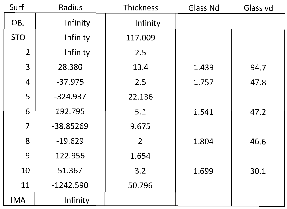
Table 12
Table 13: Embodiment 13

Table 13
Table 14: Embodiment 14

Table 14
Table 15: Embodiment 15

Table 15
Table 16: Embodiment 16

Table 16
Table 17: Embodiment 17

Table 17
Table 18: Embodiment 18

Table 19: Embodiment 19

Table 19
Table 20: Embodiment 20
Surf Radius Thickness Glass Nd Glass vd
Table 20
OBJ Infinity 187.436
1 Infinity 3
2 199.7 12 1.439 94.9
3 -32.944 2.5 1.700 48.1
4 -68.562 1
5 -121.111 5.5 1.620 36.4
6 -46.239 2.192
7 -54.448 2.5 1.613 44.5
8 -189.507 51
9 Infinity 2.5
10 46.34 1.2 1.740 28.3
11 31.72 5 1.439 94.7
12 -228.526 0.5
13 228.526 1.8 1.717 29.5
14 Infinity 3 Mag. 1 Mag. 2 Mag. 3 Mag. 4 Mag. 5 Mag. 6
15 Infinity Zml Zml: 9.684 18.902 29.333 33.731 38.794 40.334
16 -47.673 1.1 1.618 63.3
17 12.423 2.8 1.749 35.3
18 26.395 3
19 Infinity Zm2 Zm2: 31.148 21.930 11.499 7.100 2.037 0.498
STO 37.82 2 1.439 94.7
21 -27.352 1.1 1.852 40.8
22 -46.34 Zm3 Zm3: 0.400 0.488 2.659 5.326 13.533 27.375
23 Infinity 2
24 -47.673 1.1 1.618 63.3
25 12.423 2.8 1.749 35.3
26 26.395 Zm4 Zm4: 27.471 27.383 25.212 22.545 14.339 0.496
27 Infinity 3
28 126.6 6.6 1.439 94.7
29 -21.048 1.2 1.786 44.2
30 -29.59 5
31 46.44 6.3 1.439 94.7
32 200.692 0.962
33 35.11 4 1.595 67.7
34 105.44 1.483
35 29.59 6.1 1.595 67.7
36 82.34 2 1.916 31.6
37 20.7 4.768
38 114.31 8 1.689 31.1
39 -26.61 2 1.729 54.1
40 84.24 92.3718
IMA Infinity
Table 21: Embodiment 21
Surf Radius Thickness Glass Nd Glass vd
Table 21
OBJ Infinity 92.604
1 Infinity 1.5
2 -1645 2.4 1.916 31.6
3 80.5 9.9 1.439 94.7
4 -56.89 1.491
5 65 19.2 1.801 35.0
6 -69.882 2.2 1.638 42.4
7 36.35 7.2 1.439 94.7
8 202.51 51
9 Infinity 2.5
10 46.34 1.2 1.740 28.3
11 31.72 5 1.439 94.7
12 -228.526 0.5
13 228.526 1.8 1.717 29.5
14 Infinity 3 Mag. 1 Mag. 2 Mag. 3 Mag. 4 Mag. 5 Mag. 6
15 Infinity Zml Zml: 9.684 18.902 29.333 33.731 38.794 40.334
16 -47.673 1.1 1.618 63.3
17 12.423 2.8 1.749 35.3
18 26.395 3
19 Infinity Zm2 Zm2: 31.148 21.930 11.499 7.100 2.037 0.498
STO 37.82 2 1.439 94.7
21 -27.352 1.1 1.852 40.8
22 -46.34 Zm3 Zm3: 0.400 0.488 2.659 5.326 13.533 27.375
23 Infinity 2
24 -47.673 1.1 1.618 63.3
25 12.423 2.8 1.749 35.3
26 26.395 Zm4 Zm4: 27.471 27.383 25.212 22.545 14.339 0.496
27 Infinity 3
28 126.6 6.6 1.439 94.7
29 -21.048 1.2 1.786 44.2
30 -29.59 5
31 46.44 6.3 1.439 94.7
32 200.692 0.962
33 35.11 4 1.595 67.7
34 105.44 1.483
35 29.59 6.1 1.595 67.7
36 82.34 2 1.916 31.6
37 20.7 4.768
38 114.31 8 1.689 31.1
39 -26.61 2 1.729 54.1
40 84.24 92.372
IMA Infinity
Table 22: Embodiment 22
Surf Radius Thickness Glass Nd Glass vd
OBJ Infinity 32.000 Table 22
1 Infinity 1.500
2 -208.953 7.500 1.618 63.3335
3 -57.26 0.997
4 43.2 16.500 1.497 81.5459
5 -44.732 3.455
6 -33.373 2.5 1.72003 50.6222
7 277.16 16 1.497 81.5
8 -34.417 1
9 121.232 2.5 1.84666 23.8
10 48.006 12.4 1.497 81.5
11 -69.746 5.5
12 -30.9 2.5 1.638 42.4
13 -481 1.7
14 -739.9 5 1.92286 20.9
15 -77.27 51
16 Infinity 2.5
17 46.34 1.2 1.74 28.3
18 31.72 5 1.439 94.7
19 -228.526 0.5
20 228.526 1.8 1.71736 29.5
21 Infinity 3 Mag. 1 Mag. 2 Mag. 3 Mag. 4 Mag. 5 Mag. 6
22 Infinity Zml Zml: 9.684 18.902 29.333 33.731 38.794 40.334
23 -47.673 1.1 1.618 63.3
24 12.423 2.8 1.7495 35.3
25 26.395 3
26 Infinity Zm2 Zm2: 31.148 21.930 11.499 7.100 2.037 0.498
STO 37.82 2 1.43875 94.7
28 -27.352 1.1 1.8515 40.8
29 -46.34 Zm3 Zm3: 0.400 0.488 2.659 5.326 13.533 27.375
30 Infinity 2
31 -47.673 1.1 1.618 63.3
32 12.423 2.8 1.7495 35.3
33 26.395 Zm4 Zm4: 27.471 27.383 25.212 22.545 14.339 0.496
34 Infinity 3
35 126.6 6.6 1.43875 94.7
36 -21.048 1.2 1.786 44.2
37 -29.59 5
38 47.545 6.9 1.497 81.5
39 -53.666 2.5 1.6134 44.3
40 -491.1 65.6372
41 49.07 5.4 1.626 35.7
42 -17.2 2 1.804 46.6
43 22.2 30.7753
44 -31.89 4.4 1.487 70.2
45 -21.808 67.370
IMA Infinity
Part # Description Fl(mm) W.D. (mm) W.D./F1
1-81201 0.25X 400 356 0.89
1-81202 0.5X 200 174 0.87
1-81203 0.75X 133.33 100 0.75
1-81204 IX 100 90 0.9
1-81205 1.25X 80 72 0.9
1-81206 1.5X 65 45 0.69
1-81207 2X 50 30 0.6
Table 23

Table 24

2 1-81207 Mag. (X) 0.880 6.188 1.280 9.000 1.760 12.38 2.560 18.00
NA Low 1/2" 9.09 1.29 6.25 0.89 4.55 0.65 3.13 0.44 Low 0.0657 2/3" 12.50 1.78 8.59 1.22 6.25 0.89 4.30 0.61 5.11 NA High 32 1" - - 12.50 1.78 9.09 1.29 6.25 0.89 High 0.1900 4/3" 12.50 1.78 8.59 1.22 1.77
32mm 12.50 1.78
UltraZoom
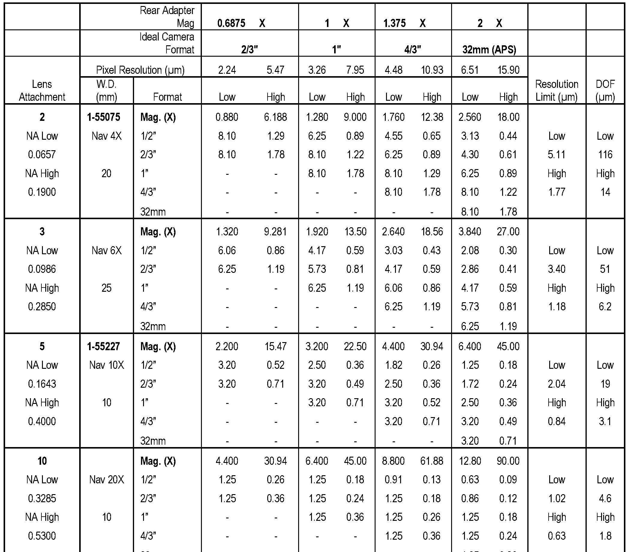
A finite conjugate camera, optical assembly, lens assembly, and/or digital microscope includes a modular optical assembly or a modular lens system. Several example embodiments are described herein that are capable of providing a range of numerical apertures or NAs across numerous sensor format sizes as well as providing zooming capability. A lens system in accordance with certain embodiments may have an advantageous amount of etendue capability, defined as the product of the pupil area and the solid angle of the field of view [Smith - Modern Optical Engineering, pg. 716, the entire book is incorporated by reference]. [Etendue = π * A * sin2 Θ] Eq. 1 [Bentley & Olson - Field Guide to Lens Design, pg. 120, the entire book is incorporated by reference], for a flat surface with a uniform solid angle, where A is the area of the surface and Θ is the half angle of the marginal ray.
An optical design of a lens having approximate etendue of 0.95 mm2sr or greater is provided that is configured to approximately fully utilize a 6.6MP sensor having a roughly 4:3 aspect ratio. A similarly designed optical system having an approximate etendue value of 4.65 mm2sr is provided that is configured to approximately fully utilize a 32MP sensor having roughly a 4:3 aspect ratio. Lens etendue system values of between approximately 0.95 to 4.65 mm2sr are provided in certain embodiments of optical assemblies that are configured to approximately reach sensor limited performance on various aspect ratios of digital or analog capturing devices with 4075 to 8194 individual sensing units across the diagonal diameter of the device. These individual sensing units are commonly referred to as pixels in digital cameras. Multiple embodiments and examples are described that include etendue preserving lens systems that incorporate a ratio of highest to lowest magnification of at least 5.5: 1 and have etendue values of between about 0.95 to 4.65 mm2sr.
The ratio of the highest magnification possible (Ml) to the lowest magnification possible (M2) is advantageous in several different embodiments of zoom lens systems that can move continuously between the high and low magnification positions, therefore providing any magnification between the high and low values. This feature is also advantageous in
embodiments including zoom lens systems that may have a continuous movement with discrete stops for specific repeatable magnification selections inside advantageous high and low magnification values.
A modular finite conjugate lens assembly is provided that includes a zooming
component. The lens assembly is configured to exhibit between 0.95 and 4.65 mm2sr of etendue,
and a ratio of highest to lowest magnification between 5.5: 1 and 16: 1. The lens assembly may exhibit a magnification 2X or more at one or more points of the zoom.
Another modular finite conjugate lens assembly is provided that includes an afocal zooming component. The lens assembly is configured to exhibit between 0.95 and 4.65 mm2sr of etendue, and a ratio of highest to lowest magnification between 5.5: 1 and 16: 1.
Another finite conjugate lens assembly is provided that includes modular interchangeable components, including a zooming component that includes three independently movable lens groups that are disposed within the lens assembly between a pair of static lens groups, and wherein the lens assembly exhibits an etendue of between 0.95 and 4.65 mm2sr.
In certain embodiments, the lens assembly may be configured to have a resolving power such that 4,075 to 8,194 individual pixels are resolvable across a diagonal of an image plane.
In certain embodiments, the lens assembly exhibits an etendue between 0.95 and 4.65 mm2sr at any point of the zoom range.
In certain embodiments, the lens assembly may be configured to exhibit between 1.57 and 4.65 mm2sr of etendue, and a ratio of highest to lowest magnification between 7: 1 and 16: 1.
In certain embodiments, the lens assembly may be configured to exhibit between 2.88 and 4.65 mm2sr of etendue, and a ratio of highest to lowest magnification between 6.2: 1 and 16: 1.
In certain embodiments, the lens assembly may include a lens attachment module coupled to face an object side of the zooming component within the lens assembly. The lens attachment module may include two or more fixed focal length lens elements, and may have a positive focal length, and may exhibit a pupil size between 16 and 25mm and/or a pupil depth of 50mm or greater. The two or more fixed focal length lens elements of the lens attachment module may include a doublet. The two or more fixed focal length lens elements of the lens attachment module may further include a triplet and/or a second doublet and one or more singlets and/or multiple singlets.
In certain embodiments, the lens assembly may include a rear adapter module coupled to face an image side of the zooming component within the lens assembly. The rear adapter module may include three or more fixed focal length lens elements, and may have a positive focal length, and may exhibit a pupil size between 16 and 25mm and/or a pupil depth of 50mm or greater. The three or more fixed focal length lens elements of the rear adapter module may include two doublets and a singlet, or a doublet and three singlets.
The lens assembly may include a core zoom module including the zooming component, and one or both of a lens attachment module and a rear adapter module.
Another modular finite conjugate lens assembly is provided that includes a zooming component that is configured to exhibit at least 1.58 mm2sr of etendue at a lowest magnification position, and a ratio of highest to lowest magnification of at least 7: 1. In certain embodiments, the lens assembly may provide a maximum magnification of 2X or greater. The lens assembly may be configured to have a resolving power such that greater than 4,075 individual pixels are resolvable across a diagonal of an image plane. The etendue of the lens assembly may be between 1.58 and 4.95 mm2sr at one or more points or at any point of a zoom range of the zooming component. The ratio of highest to lowest magnification may be between 7: 1 and 16: 1.
The lens assembly may include an afocal zooming component. The lens assembly may include a lens attachment module that is coupled at an object end of the afocal zooming component within the lens assembly. The lens attachment module may include two or more fixed focal length lens elements, and may have a positive focal length, and may exhibit a pupil size of between 16 and 25mm. The lens attachment module may exhibit a pupil depth of 75mm or greater.
The lens assembly may include a rear adapter module that is coupled at an image end of an afocal zooming component within the lens assembly. The rear adapter module may include three or more fixed focal length lens elements, and may have a positive focal length, and may exhibit a pupil size of between 16 and 25mm. The rear adapter module may exhibits a pupil depth of 75mm or greater.
The lens assembly may include an afocal zoom section that includes the zooming component.
The lens assembly may include a core zoom module including the zooming component; a lens attachment module and a rear adapter module. The lens attachment module may include two or more fixed focal length lens elements. The lens attachment module may be coupled to an object end of the core zoom module and may have a positive focal length. The rear adapter module may include three or more fixed focal length lens elements. The rear adapter module may be coupled to an image end of the core zoom module and may have a positive focal length. The lens assembly may exhibit a pupil depth of at least 75mm or a pupil size between 16 and 25mm, or both.
In certain embodiments, the lens assembly may be configured such that a wavelength focus position across a wavelength range from 430nm to 1 lOOnm differs by not more than 3x
from a DOF (depth of field) at 550nm light from a same 550nm light focus position, wherein
DOF is defined as DOF = + 2tNA2, where λ is wavelength and NA is Numerical Aperture.
The lens assembly may be configured such that a wavelength focus position across a wavelength range from 430nm to 660nm differs by not more than lx from the DOF (depth of focus) at 550nm light from a same 550nm light focus position, wherein DOF is defined as DOF = + where λ is wavelength and NA is Numerical Aperture.
The lens assembly may be configured such that a wavelength focus position across a wavelength range from 900nm to 1700nm differs by not more than 3x from the DOF (depth of focus) at 1200nm light from a same 1200nm light focus position, wherein DOF is defined as
DOF = + 2tNA2, where λ is wavelength and NA is Numerical Aperture.
A lens assembly in accordance with certain embodiments may include a core zoom module that includes the zooming component, a lens attachment module coupled at an object end of the core zoom module, and a rear adapter module coupled at an image end of the core zoom module.
In certain embodiments, a lens assembly may include an afocal zooming component. The lens assembly may include an afocal zoom module including the afocal zooming
component. A lens attachment module may be coupled at an object side of the afocal zoom module within the lens assembly. A rear adapter module may be coupled at an image side of the afocal zoom module within the lens assembly. The lens assembly may include one or more of a motorization module, a lighting module, a focusing module, a mount module, a sensor module, a processing module, and an interface module.
In certain embodiments, a zooming component may include five lens groups including, from object side to image side of the lens assembly, a positive focal length group, a negative focal length group, a third group, another negative focal length group, and another positive focal length group. The third group may be positive or negative.
In certain embodiments, the zooming component may include five lens groups including, from object side to image side of the lens assembly, a static first group, a movable second group, a third group, a movable fourth group, and a static fifth group. The third group may include a movable group. The movable second and fourth groups may have a same sign of optical power, and a movable third group may have a same or opposite sign of optical power as the movable second and fourth groups. The third group may include a static group.
In certain embodiments, the zooming component may include five lens groups including, from object side to image side of the lens assembly, a static positive group, a negative movable group, a positive static group, a negative movable group, and a positive static group.
In certain embodiments, the zooming component may include five lens groups including, from object side to image side of the lens assembly, a static positive group, a negative movable group, a positive movable group, a negative movable group, and a static positive group.
In certain embodiments, the zooming component may include five lens groups including, from object side to image side of the lens assembly, a static positive group, a negative movable group, a negative movable group, a negative movable group, and a positive static group.
In certain embodiments, the zooming component may include three movable groups. The three movable groups may be disposed consecutively within the lens assembly. The three movable groups may be disposed between a pair of static groups within the lens assembly.
In certain embodiments, the zooming component may include five lens groups including, from object side to image side of the lens assembly, a static group, a movable triplet, a third group, a movable doublet, and another static group. The third group may include a doublet. The third group may be static or movable.
In certain embodiments, the zooming component may include, from object side to image side of the lens assembly, a static group, a positive movable group, another movable group, another positive movable group, and another static group. The zooming component may include three consecutive independently movable positive lens groups. The three consecutive independently movable lens groups may include an independently movable negative lens group disposed between a pair of independently movable positive lens groups.
A lens assembly may be configured such that a telecentric chief ray value at an object is less than 2° relative to a flat perpendicular object when combined with the zooming component.
A lens attachment module including a lens attachment lens assembly is also provided herein. The lens attachment module is configured for coupling with a zoom module for use as part of a zoom lens system. The lens attachment lens assembly includes two or more lens elements and has a positive focal length. The lens attachment lens assembly is configured to exhibit a pupil size of between 16 and 25mm and a pupil depth greater than 50mm.
In certain embodiments, the lens attachment lens assembly may exhibit an etendue between 0.95 and 4.65 mm2sr and may be configured to work in conjunction with said zoom module with 50% or less vignetting through a zoom range of the zoom module.
In certain embodiments, the lens attachment lens assembly may exhibit a pupil depth that is greater than 75mm. The lens assembly may be configured such that pupil aberrations are matched to the zoom module to reduce system aberration, thereby improving system
performance.
In certain embodiments, the lens attachment module may be configured for coupling at an object end of a zoom module that also has a rear adapter module coupled at an image end within the lens assembly. The lens assembly may also include one or more of a motorization module, a lighting module, a focusing module, a mount module, a sensor module, a processing module, and an interface module coupled together within said lens assembly.
In certain embodiments, two or more lens elements of the lens attachment lens assembly may include a doublet, and either a triplet; a second doublet and a singlet; and/or two or three singlets.
A rear adapter module including a rear adapter lens assembly is also provided herein. The rear adapter module is configured for coupling with a zoom module for use as part of a zoom lens system. The rear adapter lens assembly includes three or more lens elements and has a positive focal length. The rear adapter lens assembly is configured to exhibit a pupil size of between 16 and 25mm and a pupil depth greater than 50mm.
In certain embodiments,the rear adapter lens assembly may be configured to exhibit between 0.95 and 4.65 mm2sr. The rear adapter lens assembly may be configured to work in conjunction with a zoom module with 50% or less vignetting through a zoom range of the zoom module.
In certain embodiments, the rear adapter lens assembly may exhibit a pupil depth that is greater than 75mm. The rear adapter lens assembly may be configured such that pupil aberrations are matched to the zoom module to reduce system aberration, thereby improving system performance.
In certain embodiments, the rear adapter module may be coupled at an image end of a zoom module that also has a lens attachment module coupled at an object end. One or more of a motorization module, a lighting module, a focusing module, a mount module, a sensor module, a processing module, and an interface module may also be coupled together within the lens assembly.
In certain embodiments, the rear adapter lens assembly of the rear adapter module may include a doublet and three or more singlets, or two doublets and one or more singlets.
A finite conjugate camera is also provided including a finite conjugate lens assembly, e.g., as set forth at any of the example embodiments described herein; an image sensor disposed at an image plane of the optical assembly for capturing images; and a display or interface for communicating with an external display, or both, for displaying the images captured at the image sensor. The finite conjugate camera may be configured as a digital microscope.
A finite conjugate camera is also provided including a finite conjugate lens assembly, e.g., as set forth at any of the example embodiments described herein; and an eyepiece configured and positioned such that images produced by the optical assembly are viewable by looking through the eyepiece. The finite conjugate camera may be configured as a microscope.
Another finite conjugate camera is provided that includes:
(a) an afocal zoom module including a zoom lens assembly including five lens groups including, from object end to image end (i) a first positive static group including a doublet, a triplet, two doublets, or a doublet and a singlet; (ii) a first negative movable group including a triplet, or one or two doublets, or a doublet and a singlet; (iii) a third group including a doublet, or a triplet, or three singlets, or a doublet and a singlet; (iv) a second negative movable group including one or two doublets, or a triplet, or a doublet and a singlet; and (v) a second positive static group including a triplet, a doublet, or a doublet and a singlet, or two doublets;
(b) a lens attachment module coupled to the object end of the zoom module, wherein the lens attachment module comprises a lens attachment lens assembly including (i) a doublet and a triplet, or (ii) two doublets and a singlet, or (iii) a doublet and three singlets, or (iv) a doublet and two singlets, or (v) three doublets, or (vi) three doublets and a singlet; or (vii) a triplet and a doublet and a singlet, or (viii) a triplet and two doublets, or (ix) two doublets and three singlets, or (x) two doublets and four singlets;
(c) a rear adapter module coupled to an image end of the zoom module, wherein the rear adapter module comprises a rear adapter lens assembly including (i) one doublet and three singlets, or (ii) two doublets and a singlet; and
(d) an image sensor or eyepiece disposed at an image plane.
Another finite conjugate camera is provided, including, from object end to image end:
(a) a lens attachment module that comprises a lens attachment lens assembly including (i) a doublet and a triplet, or (ii) a doublet with two or more singlets, or (iii) two doublets and one or more singlets;
(b) an afocal zoom module exhibiting a ratio of highest to lowest magnification between 5.5: 1 and 16: 1 and an etendue between 0.95 and 4.65 mm2sr, and including a zoom lens
assembly including (i) a first positive focal length static group including a triplet or a doublet and a singlet; (ii) a first negative focal length movable group including a triplet, or one or two doublets, or a doublet and a singlet; (iii) a third static or movable group including a doublet, or a triplet, or three singlets; (iv) a second negative focal length movable group including one or two doublets, or a doublet and a singlet; and (v) a second positive focal length static group including a triplet, a doublet, or a doublet and a singlet;
(c) a rear adapter module that comprises a rear adapter lens assembly including (i) a doublet and three singlets, or (ii) two doublets and a singlet, or (iii) two doublets and two singlets, or (iv) a doublet and four singlets; and
(d) an image sensor or eyepiece disposed at an image plane.
Optical assemblies in accordance with certain embodiments may include a zooming component that is configured such that a ratio of highest to lowest magnification is within a range between 5.5: 1 and 16: 1. Example embodiments of the optical layout of a finite conjugate camera or microscope are schematically illustrated in Figures 24A-24C, 25A-25C, and 26A-26C. A finite conjugate optical assembly is typically used to image objects that are disposed at distances of less than 21 times the focal length of the optical assembly. A finite conjugate optical assembly may be combined with an image sensor to form a finite conjugate camera or an eyepiece may be used to view objects with the naked eye. A finite conjugate camera may include a display, a processor, memory for storing images, and wired and/or wireless
communications interfaces for receiving and/or transmitting image data.
Several example embodiments are provided of optical assemblies that include one of a multitude of positive focal length lens attachment options, which may be provided as a lens attachment module ml as in Figure 27 A, or module ml 24, module ml 25 or module ml 26 as in the example embodiments that are schematically illustrated at Figures 24A-24C, 25A-25C or 26A-26C, respectively. Further example lens attachment modules are described herein with reference to Figures 18-23 and Tables 14-19, including examples of first lens groups Gl 14- G122, respectively, wherein the "first" lens group is disposed between the object and the other six lens groups, i.e., closest to the object of the seven lens groups, and disposed on the object end of the core zoom module m2 as in Figure 27A, or module m224, module m225 or module m226 as in Figures 24A-24C, 25A-25C and 26A-26C, respectively. Further example lens attachment modules are described herein with reference to Figure 27G, including example lens attachment modules ml27, ml28, ml29, ml30, ml31, ml32 and ml33 which may be configured in accordance with any of the examples set forth at Table 23. Optical assemblies in accordance
with certain lens attachment embodiments may resemble large field of view (FOV) microscope objectives. A lens attachment module ml as in Figure 27A may be configured in certain embodiments to allow varying working distances, object NA values, fields of view, and/or telecentricity levels.
Several example embodiments are also provided of optical assemblies that include a zooming component, or core zoom module m2 as in Figure 27A, including the example core zoom modules m224, m225, and m226 of the example embodiments that are schematically illustrated at Figures 24A-24C, 25A-25C or 26A-26C, respectively, and described at Tables 20- 22. Further example zoom modules are described herein with reference to Figures 5A-11C, and Tables 1-7. Each of the example zoom modules of Figures 5A-11C and 24A-26C, respectively include, from object end to image end of the optical assembly, a second lens group G201-G207 and G220-G222, a third lens group G301-G307 and G320-G322, a fourth lens group G401-G407 and G420-G422, a fifth lens group G501-G507 and G520-G522, and a sixth lens group G601- G607 and G620-G622. Further zoom module examples are described herein with reference to Figure 27E including examples of core zoom modules m227, m228, m229, m230 and m231. Zoom modules m2 as in Figure 27A in accordance with certain embodiments include afocal zoom modules and provide ratios of highest to lowest magnification between 5.5: 1 and 16: 1.
Several example embodiments are also provided of optical assemblies that include one of a multitude of positive focal length rear adapter options, which may be provided as a rear adapter module m3 as in Figure 27A, or as module m324, module m325 or module m326 of the example embodiments that are described herein with reference to Figures 24A-24C, 25A-25C or 26A- 26C, respectively, and Tables 20-22, wherein the rear adapter module m324 of Figures 24A-24C includes a seventh lens group G720 which is disposed between the core zoom module and the image plane, and rear adapter module m325 of Figures 25A-25C includes lens group G721, and rear adapter module m326 of Figures 26A-26C includes lens group G722. Further examples of rear adapter modules are described herein with reference to Figures 12-17 and Tables 8-13, including example seventh lens groups G708-G713, respectively. Further example rear adapter modules m327, m328, m329 and m330 are schematically illustrated at Figure 27C and may be configured in accordance with any of the examples set forth at Table 24. Rear adapter optical assemblies in accordance with certain embodiments may include or resemble tube lenses. A rear adapter module m3 as in Figure 27A may be configured in certain embodiments to allow varying sensor size coverage and sensor side NA values.
The optical assembly that is schematically illustrated at Figures 4A-4C does not have separate modules, and instead has static groups G10 and G20 and G60 and G70 as included groups, along with groups G30 and G50 (but not G40) within a single lens assembly. Each of the six lens groups G10, G20, G30, G50, G60 and G70 of the optical assembly of Figures 4A-4C consists of one doublet, such that the optical assembly of Figures 4A-4C consists of six doublets, wherein the first doublet includes a convex meniscus lens coupled to a biconvex lens as lens group G10, the second doublet includes a biconvex lens coupled to a concave meniscus lens as lens group G20, the third doublet includes a concave meniscus lens coupled to a biconcave lens as lens group G30, a fourth doublet includes a biconcave lens coupled to a convex meniscus lens as lens group G50, a fifth doublet includes a convex meniscus lens coupled to a biconvex lens as lens group G60, and a sixth doublet includes a biconvex lens coupled to a concave meniscus lens as lens group G70. The modular approach, extra lens group, and high etendue are each advantageous features of a finite conjugate optical assembly and camera in accordance with several embodiments described herein that are not found in the less capable system illustrated at Figures 4A-4C.
A core zoom module m2 of Figure 27 A, or module m224, module m225 or module m226 of Figures 24A-24C, 25A-25C or 26A-26C, respectively, of an example finite conjugate optical assembly, may be configured in accordance with the examples illustrated schematically at Figures 5A-11C, 24A-26C, 27A and/or 27E, and may be configured in accordance with one or a combination of the example optical prescriptions shown in Tables 1-7 and 20-22. A core zoom module m2 in accordance with several example embodiments described herein includes five lens groups, while the zoom optical assembly illustrated at Figures 4A-4C includes only four groups.
Figures 27A-27G schematically illustrate an embodiment of a modular camera system that includes a lens attachment module ml in the camera system of Figure 27 A, while examples of lens attachment modules ml27, ml28, ml29, ml30, ml31, ml32 and ml33 are provided at Figure 27G. A core zoom module m2 and a rear adapter module m3 are also included in the camera system of Figure 27 A, while examples of core zoom modules m227, m228, m229, m230, m231 are provided at Figure 27E and examples of rear adapter modules m327, m328, m329 and m330 are provided at Figure 27C. The camera system of Figure 27A also includes a camera mount cm, and Figure 27B includes examples of camera mounts cml, cm2 and cm3. Figures 27 A and 27D include flat mount fml and split clamp scl components for coupling the complete lens system such as the optical assemblies illustrated schematically in Figures 24A - 24C to an external fixture. The camera system of Figure 27A also includes a lighting component lc, while
Figure 27F includes examples of lighting component options LED lcl and coax lc2, and includes a schematic illustration of a coupler cc for facilitating coupling of a lens attachment module ml at an object end of a zoom module m2. Multiple further example embodiments are provided for the lens attachment module ml, core zoom module m2, and rear adapter module m3, and are described with reference to Figures 5A-26C and Tables 1-25. A modular design in accordance with alternative embodiments may contain two or more modules or modular components that may be conveniently individually isolated for repair or replacement or calibration separate from one or more other modules. A sensor module may be included in an imaging system in accordance with certain embodiments. Other module configurations may include a motorization module, a lighting module, a processing module, an interface module, a communication module or combinations of these.
In certain embodiments, pupil aberrations are controlled more greatly than in other embodiments, thus advantageously allowing the modularity of the system to function optimally. Optical assemblies in accordance with certain embodiments will have a system magnification greater than 2X at their high magnification point.
CORE ZOOM MODULE
Further example embodiments for afocal zoom lens groups of core zoom module m2 of Figures 27 A and 27E may include or otherwise be configured in accordance with one or more of the following features. Afocal zoom lenses are provided in accordance with certain
embodiments that are configured such as to compress the pupil to a low total movement compared with conventional designs. Optical aberrations may be tightly controlled in these embodiments. These together allow better integration of a multitude of objective lenses and tube lenses that provide optimal performance along with the core zoom. This improved total system performance allows for larger apertures and fields of view than previously available. Combined together this leads to more optical bandwidth, represented by an etendue value at the maximum etendue point which is at the low magnification zoom position at the exit pupil of 0.95 to 4.65mm2sr for optical systems configured in accordance with certain embodiments for use with 6.6MP to 32MP sensors, respectively.
A first example embodiment of a core zoom module that includes an afocal zoom lens assembly and exhibits a 7: 1 ratio of highest to lowest magnification, and an approximate etendue of 1.57 mm2sr at its low magnification position. This embodiment is illustrated schematically at Figures 5A-5C, and includes a positive group (G201), a movable negative group (G301), a
movable positive group (G401), a movable negative group (G501), and a positive group (G601). A numerical example in accordance with this embodiment is provided in Table 1. Three arrangements are included in Figure 5A-5C, including a low magnification arrangement at Figure 5 A, a mid-level magnification arrangement at Figure 5B, and a high magnification arrangement at Figure 5C.
The example lens group G201 in Figures 5A-5C includes two lens elements including three lenses. The lens group G201 includes a doublet and a singlet, wherein the doublet includes a biconvex lens coupled to a concave meniscus lens, and wherein the singlet includes a convex meniscus lens.
The example movable lens group G301 in Figures 5A-5C includes one lens element including two lenses. The lens group G301 includes a doublet, wherein the doublet includes a biconcave lens coupled to a convex meniscus lens. The movable lens group G301 is disposed a greater distance from lens group G201 in Figure 5B compared with Figure 5 A, and lens group G301 is disposed closer to lens group G401 in Figure 5B compared with Figure 5A. The movable lens group G301 is disposed a greater distance from lens group G201 in Figure 5C compared with Figure 5B, and lens group G301 is disposed closer to lens group G401 in Figure 5C compared with Figure 5B.
The movable lens group G401 includes three lens elements including three lenses. The lens group G401 includes a convex meniscus singlet, a biconvex singlet and a concave meniscus singlet. The movable lens group G401 is disposed furthest from lens group G301 and closest to lens group G501 is Figure 5 A, compared with Figures 5B-5C, and lens group G401 is disposed closest to lens group G301 and furthest form lens group G501 in Figure 5C compared with Figures 5A-5B.
The movable lens group G501 includes one lens element including two lenses. The lens group G501 includes a doublet, wherein the doublet includes a biconcave lens coupled to a convex meniscus lens. The lens group G501 is disposed about a same distance from lens group G601 in Figures 5 A and 5B, and is closest to lens group G601 in Figure 5C compared with Figures 5A-5B. The lens group G501 is disposed closest to lens group G401 in Figure 5A compared with Figures 5B-5C, and is disposed furthest from lens group G401 in Figure 5C compared with Figures 5A-5B.
The lens group G601 includes two lens elements including three lenses. The lens group G601 includes a concave meniscus singlet and a doublet, wherein the doublet includes a concave meniscus (or plano-convex) lens coupled to a concave meniscus lens.
A second embodiment of a core zoom module including an afocal zoom lens assembly that has a 7: 1 ratio of highest to lowest magnification, and an approximate etendue of 1.57 mm2sr of etendue at its low magnification position. This embodiment is illustrated schematically at Figures 6A-6C, and includes a positive group (G202), a movable negative group (G302), a static positive group (G402), a movable negative group (G502), and a positive group (G602). A numerical example in accordance with this embodiment is provided in Table 2. Three arrangements are included in Figures 6A-6C, including a low magnification arrangement at Figure 6A, a mid-level magnification arrangement at Figure 6B, and a high magnification arrangement at Figure 6C.
The lens group G202 includes two lens elements including three lenses. The lens group
G202 includes a doublet and a singlet, wherein the doublet includes a convex meniscus lens coupled to a biconvex (or convexo-plano) lens, and wherein the singlet includes a convex meniscus (or convex-piano) lens.
The movable lens group G302 includes one lens element including two lenses. The lens group G302 includes a doublet, wherein the doublet includes a biconcave lens coupled to a convex meniscus lens. The movable lens group G302 is disposed a greater distance from lens group G202 in Figure 6B compared with Figure 6A, and lens group G302 is disposed closer to lens group G402 in Figure 6B compared with Figure 6A. The movable lens group G302 is disposed a greater distance from lens group G202 in Figure 6C compared with Figure 6B, and lens group G302 is disposed closer to lens group G402 in Figure 6C compared with Figure 6B.
The lens group G402 includes one lens element including two lenses. The lens group G402 includes a doublet, wherein the doublet includes a biconvex lens coupled to a concave meniscus lens. The lens group G402 is disposed at a same location relative to the static groups G202 and G602 in all three of Figures 6A, 6B and 6C. The lens group G402 is a static group in this example.
The movable lens group G502 includes one lens element including two lenses. The lens group G502 includes a doublet, wherein the doublet includes biconcave lens coupled to a convex meniscus lens. The lens group G502 is disposed closest to group G402 in Figure 6A compared with Figures 6B-6C, and lens group G502 is disposed furthest from group G402 in Figure 6C compared with Figures 6A-6B. The lens group G502 is disposed furthest from group G602 in Figure 6A compared with Figures 6B-6C, and group G502 is disposed closest to group G602 in Figure 6C compared with Figures 6A-6B.
The lens group G602 includes one lens element including two lenses. The lens group G602 includes a doublet, wherein the doublet includes a biconvex (or plano-convex) lens coupled to concave meniscus lens.
A third embodiment of a core zoom module includes an afocal zoom lens assembly configured to have a 7: 1 ratio of highest to lowest magnification, and an approximate etendue of 1.58 mm2sr at its low magnification position. This embodiment is illustrated schematically at Figures 7A-7C, and includes a positive group (G203), a movable negative group (G303), a movable negative group (G403), a movable negative group (G503), and a positive group (G603). A numerical example in accordance with this embodiment is provided in Table 3. Three arrangements are included in Figures 7A-7C, including a low magnification arrangement at Figure 7A, a mid-level magnification arrangement at Figure 7B, and a high magnification arrangement at Figure 7C.
The lens group G203 includes one lens element including two lenses. The lens group G203 includes a doublet, wherein the doublet includes a biconvex lens coupled to a concave meniscus lens.
The movable lens group G303 includes one lens element including two lenses. The lens group G303 includes a doublet, wherein the doublet includes a concave meniscus lens coupled to a biconcave lens. The movable lens group G303 is disposed a greater distance from lens group G203 in Figure 7B compared with Figure 7A, and lens group G303 is disposed closer to lens group G403 in Figure 7B compared with Figure 7A. The movable lens group G303 is disposed a greater distance from lens group G203 in Figure 7C compared with Figure 7B, and lens group G303 is disposed closer to lens group G403 in Figure 7C compared with Figure 7B.
The movable lens group G403 includes one lens element including two lenses. The lens group G403 includes a doublet, wherein the doublet includes a biconvex lens coupled to a biconcave or meniscus lens. The movable lens group G403 is disposed furthest from lens group G303 and closest to lens group G503 in Figure 7C, compared with Figures 7A-7B, and lens group G403 is disposed closest to lens group G303 and furthest from lens group G503 in Figure 7A compared with Figures 7B-7C.
The movable lens group G503 includes one lens element including two lenses. The lens group G503 includes a doublet, wherein the doublet includes a biconcave lens coupled to a convex meniscus lens. The lens group G503 is disposed about a same distance from lens group G603 in Figures 7A and 7C, and is furthest from lens group G603 in Figure 7B compared with Figures 7A and 7C. The lens group G503 is disposed about a same distance from lens group
G403 in Figures 7B and 7C, and group G503 is disposed furthest from lens group G403 in Figure 7 A compared with Figures 7B-7C, and group G503 is disposed furthest from lens group G303 in Figure 7A compared to Figures 7B-7C and group G503 is disposed closest to lens group G303 in Figure 7C compared to Figures 7A-7B.
The lens group G603 includes one lens element including three lenses. The lens group
G603 includes a triplet, wherein the triplet includes a convex meniscus lens coupled to a biconvex lens, and the biconvex lens is also coupled to a concave meniscus lens.
A fourth embodiment of a core zoom module includes an afocal zoom lens assembly that has a 16: 1 ratio of highest to lowest magnification, and an approximate etendue of 1.58 mm2sr at its low magnification position. This embodiment is illustrated schematically at Figures 8A-8C, and includes a positive group (G204), a movable negative group (G304), a movable positive group (G404), a movable negative group (G504), and a positive group (G604). A numerical example in accordance with this embodiment is provided in Table 4. Three arrangements are included in Figures 8A-8C, including a low magnification arrangement at Figure 8A, a mid-level magnification arrangement at Figure 8B, and a high magnification arrangement at Figure 8C.
The lens group G204 includes two lens elements including four lenses. The lens group G204 includes two doublets, wherein each doublet includes a biconvex lens coupled to a concave meniscus lens.
The movable lens group G304 includes one lens element including three lenses. The lens group G304 includes a triplet, wherein the triplet includes a concave meniscus lens coupled to a biconcave lens, and the biconcave lens is also coupled to a convex meniscus lens. The movable lens group G304 is disposed a greater distance from lens group G204 in Figure 8B compared with Figure 8A, and lens group G304 is disposed closer to lens group G404 in Figure 8B compared with Figure 8A. The movable lens group G303 is disposed a greater distance from lens group G204 in Figure 8C compared with Figure 8B, and lens group G303 is disposed closer to lens group G404 in Figure 8C compared with Figure 8B.
The movable lens group G404 includes one lens element including two lenses. The lens group G404 includes a doublet, wherein the doublet includes a biconvex lens coupled to a concave meniscus or biconcave (or plano-concave) lens. The movable lens group G404 is disposed closest to lens group G304 and furthest from lens group G504 in Figure 8C, compared with Figures 8A-8B, and lens group G404 is disposed about a same distance from group G504 in Figures 8A and 8B, and lens group 404 is disposed further from lens group G304 in Figure 8A compared with Figures 8B-8C.
The movable lens group G504 includes one lens element including two lenses. The lens group G504 includes a doublet, wherein the doublet includes a biconcave (or plano-concave) lens coupled to a convex meniscus lens. The lens group G504 is disposed furthest from lens group G604 in Figure 8A compared with Figures 8B-8C, and group G504 is disposed closest to group G604 in Figure 8C compared with Figures 8A-8B, and lens group G504 is disposed closer to group G604 in Figure 8B compared to Figure 8A.
The lens group G604 includes one lens element including three lenses. The lens group G604 includes a triplet, wherein the triplet includes a convex meniscus lens coupled to a biconvex lens, and the biconvex lens is also coupled to a concave meniscus lens.
A fifth embodiment of a core zoom module includes an afocal zoom lens assembly that exhibits a 6.2: 1 ratio of highest to lowest magnification, and an approximate etendue of 2.88 mm2sr at its low magnification position. This embodiment is illustrated schematically at Figures 9A-9C, and includes a positive group (G205), a movable negative group (G305), a movable negative group (G405), a movable negative group (G505), and a positive group (G605). A numerical example in accordance with this embodiment is provided in Table 5. Three arrangements are included in Figures 9A-9C, including a low magnification arrangement at Figure 9A, a mid-level magnification arrangement at Figure 9B, and a high magnification arrangement at Figure 9C.
The lens group G205 includes two lens elements including three lenses. The lens group G205 includes a biconvex singlet and a doublet, wherein the doublet includes a biconvex lens coupled to a biconcave lens.
The movable lens group G305 includes one lens element including three lenses. The lens group G305 includes a triplet, wherein the triplet includes a concave meniscus lens coupled to a biconcave lens, and the biconcave lens is also coupled to convex meniscus lens. The movable lens group G305 is disposed a greater distance from lens group G205 in Figure 9B compared with Figure 9A, and lens group G305 is disposed closer to lens group G405 in Figure 9B compared with Figure 9A. The movable lens group G305 is disposed a greater distance from lens group G205 in Figure 9C compared with Figure 9B, and lens group G305 is disposed closer to lens group G405 in Figure 9C compared with Figure 9B.
The movable lens group G405 includes one lens element including two lenses. The lens group G405 includes a doublet, wherein the doublet includes a biconvex (or plano-convex) lens coupled to a biconcave (or plano-concave) lens. The movable lens group G405 is disposed furthest from lens group G305 and also furthest from lens group G505 in Figure 9A compared
with Figures 9B-9C, and lens group G405 is disposed closest to lens group G305 in Figure 9C compared with Figures 9A-9B, and lens group G405 is disposed about the same distance from lens group G505 in Figures 9B and 9C, and is furthest from lens group G505 in Figure 9A compared with Figures 9B-9C.
The movable lens group G505 includes one lens element including two lenses. The lens group G505 includes a doublet, wherein the doublet includes a biconcave lens coupled to a biconvex (or convex-piano) lens. The lens group G505 is disposed about a same distance from lens group G605 in Figures 9A and 9C, and is furthest from lens group G605 in Figure 9B compared with Figures 9A and 9C. The lens group G505 is disposed about a same distance from lens group G405 in Figures 9B and 9C, and group G505 is disposed furthest from lens group G405 in Figure 9A compared with Figures 9B-9C, and group G505 is disposed furthest from lens group G305 in Figure 9A compared to Figures 9B-9C and group G505 is disposed closest to lens group G305 in Figure 9C compared to Figures 9A-9B.
The lens group G605 includes two lens elements including three lenses. The lens group G605 includes a biconvex singlet and a doublet, wherein the doublet includes a concave meniscus (or plano-convex) lens coupled to a concave meniscus lens.
A sixth embodiment of a core zoom module includes an afocal zoom lens assembly that is configured to have a 12: 1 ratio of highest to lowest magnification, and an approximate etendue of 2.88 mm2sr at its low magnification position. This embodiment is illustrated schematically at Figures 1 OA- IOC, and includes a positive group (G206), a movable negative group (G306), a movable positive group (G406), a movable negative group (G506), and a positive group (G606). A numerical example in accordance with this embodiment is provided in Table 6. Three arrangements are included in Figures 1 OA- IOC, including a low magnification arrangement at Figure 10A, a mid-level magnification arrangement at Figure 10B, and a high magnification arrangement at Figure IOC.
The lens group G206 includes one lens element including three lenses. The lens group G206 includes a triplet, wherein the triplet includes a convex meniscus lens coupled to a biconvex lens, and the biconvex lens is also coupled to a concave meniscus lens.
The movable lens group G306 includes two lens elements including four lenses. The lens group G306 includes two doublets, wherein the first doublet includes a biconvex (or planoconvex) lens coupled to biconcave lens, and the second doublet includes a biconcave (or planoconcave) lens coupled to a convex meniscus lens. The movable lens group G306 is disposed a greater distance from lens group G206 in Figure 10B compared with Figure 10A, and lens group
G306 is disposed closer to lens group G406 in Figure 10A compared with Figure 10B. The movable lens group G306 is disposed a greater distance from lens group G206 in Figure IOC compared with Figure 10B, and lens group G306 is disposed closer to lens group G406 in Figure IOC compared with Figure 10A. Lens group G306 is disposed furthest from lens groups G206 and G406 in Figure 10B compared to Figures 10A and IOC.
The movable lens group G406 includes one lens element including two lenses. The lens group G406 includes a doublet, wherein the doublet includes a biconvex lens coupled to a concave meniscus lens. The movable lens group G406 is disposed closest to lens group G506 in Figure 10A compared with Figures lOB-lOC, and group G406 is furthest from lens group G506 in Figure IOC, compared with Figures 10A-10B.
The movable lens group G506 includes two lens elements including four lenses. The lens group G506 includes two doublets, wherein the first doublet includes a biconcave (or planoconcave) lens coupled to a biconvex lens, and the second doublet includes a biconcave lens coupled to convex meniscus (or plano-concave) lens. The lens group G506 is disposed furthest from lens group G606 in Figure 10A compared with Figures lOB-lOC, and group G506 is disposed closest to group G606 in Figure IOC compared with Figures 10A-10B, and lens group G506 is disposed closer to group G606 in Figure 10B compared to Figure 10A.
The lens group G606 includes one lens element including two lens elements including three lenses. The lens group G606 includes a biconvex singlet and a doublet, wherein the doublet includes a convex meniscus lens coupled to a biconvex lens.
A seventh embodiment of a core zoom module includes an afocal zoom lens assembly that has a 5.7: 1 ratio of highest to lowest magnification, and exhibits an approximate etendue of 4.65 mm2sr at its low magnification position. This embodiment is illustrated schematically at Figures 11 A-l 1C, and includes a positive group (G207), a movable negative group (G307), a fixed positive group (G407), a movable negative group (G507), and a positive group (G607). A numerical example in accordance with this embodiment is provided in Table 7. Three arrangements are included in Figures 11 A-l 1C, including a low magnification arrangement at Figure 11 A, a mid-level magnification arrangement at Figure 1 IB, and a high magnification arrangement at Figure 11C.
The lens group G207 includes one lens element including three lenses. The lens group
G207 includes a triplet, wherein the triplet includes a convex meniscus lens coupled to a biconvex lens, and the biconvex lens is also coupled to a concave meniscus lens.
The movable lens group G307 includes one lens element including three lenses. The lens group G307 includes a triplet, wherein the triplet includes a concave meniscus lens coupled to a biconcave lens, and the biconcave lens is also coupled to a convex meniscus lens. The movable lens group G307 is disposed a greater distance from lens group G207 in Figure 1 IB compared with Figure 11 A, and lens group G307 is disposed closer to lens group G407 in Figure 1 IB compared with Figure 11 A. The movable lens group G307 is disposed a greater distance from lens group G207 in Figure 1 IC compared with Figure 1 IB, and lens group G307 is disposed closer to lens group G407 in Figure 1 IC compared with Figure 1 IB.
The lens group G407 includes one lens element including two lenses. The lens group G407 includes a doublet, wherein the doublet includes a biconvex lens coupled to a concave meniscus lens. The lens group G407 is disposed at a same location relative to the static groups G207 and G607 in all three of Figures 11 A, 1 IB and 1 IC. The lens group G407 is a static group in this example.
The movable lens group G507 includes two lens elements including four lenses. The lens group G507 includes two doublets, wherein the first doublet includes a biconcave lens coupled to a biconvex lens, and the second doublet includes a biconcave lens coupled to a convex meniscus lens. The lens group G507 is disposed closest to group G407 in Figure 11 A compared with Figures 1 lB-1 IC, and lens group G507 is disposed furthest from group G407 in Figure 1 IC compared with Figures 11 A-l IB. The lens group G507 is disposed furthest from group G607 in Figure 11 A compared with Figures 1 lB-1 IC, and group G507 is disposed closest to group G607 in Figure 1 IC compared with Figures 11 A-l IB.
The lens group G607 includes one lens element including three lenses. The lens group G607 includes a triplet, wherein the triplet includes a convex meniscus lens coupled to a biconvex lens, and the biconvex lens also coupled to a concave meniscus lens.
Additional core zoom module embodiments may include five optical groups that have similar general attributes as those illustrated schematically at Figures 5 A-l IC and/or numerically at Tables 1-7. For example, a lens attachment group, such as any of example lens groups Gl 14- G122 of Figures 18-26C and/or a rear adapter group, such as any of example lens groups G708- G712 of Figures 12-17 and lens groups G720-G722 of Figures 24A-26C may be included in additional embodiments either as separate optical modules or with the core zoom components in a single module. Example embodiments of optical assemblies including a lens attachment module ml, a core zoom module m2, and a rear adapter module m3 in combination are schematically illustrated at Figures 24A-24C, 25A-25C, 26A-26C, and 27A-27G, and given as
numerical examples in Tables 20-25. Example embodiments of lens assemblies are configured with various ratios of highest to lowest magnification between 5.5 : 1 and 16: 1 as well as etendue values between 0.95and 4.65 mm2sr, and various combinations are provided in accordance with further embodiments. Further embodiments may include larger diameter and longer optical path length designs to correct additional aberrations that may be present in high etendue designs and/or the zoom range of larger magnification ratios.
Additional design features such as more optical elements per group or aspheric elements may be included to achieve difficult performance goals including reduced optical losses from the diffraction limit and reduced vignetting compared with conventional systems, e.g., in additional embodiments that may be variations or combinations of the embodiments described herein.
Further alternative embodiments of zoom modules with five lens groups are provided for each of at least three grouping types, including, but not limited to, type 1, wherein a zoom module includes from object end to image end a positive static group, a negative movable group, a positive fixed group, a negative movable group, and a positive static group; and type 2, wherein a zoom module includes from object end to image end a positive static group, a negative movable group, a positive movable group, a negative movable group, and a positive static group; and type 3, wherein a zoom module includes from object end to image end a positive static group, a negative movable group, a negative movable group, a negative movable group, and a positive static group, as each provides distinct advantages for aberration correction and pupil compression. In various alternative embodiments, the middle group of the five lens groups of a zoom module may include a positive or negative movable group or a static group.
An afocal zoom lens assembly in accordance with certain embodiments may be designed for very good optical correction of color aberrations. A lens may be corrected to have an axial color separation of less than or equal to the depth of focus of light for the given wavelength and aperture of the system, as defined by the Rayleigh Criterion depth of focus equation,
DOF = + 2tNA2, [Smith - Modern Optical Engineering, pg. 715], for the visible wavelengths of light, defined here as 430 to 670nm. This becomes particularly advantageous for a zoom lens of extended range such as 5.5 : 1 to 16: 1 as set forth in accordance with certain embodiments.
An optical assembly in accordance with certain embodiments may be configured to achieve less than triple (3X), less than double (2X), less than IX, or even less than half (0.5X) the DOF (depth of field) of axial color separation relative to a 550nm wavelength for a 430 to
1 lOOnm waveband that covers the visible and Near Infrared (NIR) spectrums, when paired with a modular objective and tube lens in accordance with certain embodiments. The axial color separation of wavelengths achieved by an optical assembly in accordance with certain embodiments in this wavelength range may be as low as a quarter of the DOF.
Assembly adjustments of the described example embodiments may be used to correct the color separation for the 900 to 1700nm wavelength range, or the Short-Wave Infrared (SWIR). Similarly, the axial color separation of wavelengths in this range, relative to a 1200nm wavelength, for optical assemblies in accordance with certain embodiments are less than 3X the DOF, or less than 2X the DOF in certain embodiments, or less than IX, or even less than half the DOF in alternative embodiments down to as low as approximately a quarter the DOF of axial color separation of wavelengths in this range.
This low slope axial color change in the NIR and SWIR gives users the ability to use the same lens system for inspecting both visible and infrared applications. The added wavelength focusing capability, similar to the higher aperture, gives added capability of collecting information about a specimen. As an embodiment usage example, this capability could allow the surface of a part to be inspected in fine detail with short wavelength blue light, while
sequentially being able to be investigated for sub surface damage via NIR light, with or without any mechanical refocusing mechanism and/or software focus routine.
At the high magnification setting, where microscopy -like images are taken, the entire spectrum from 430nm to 1 lOOnm may be controlled to less than the depth of focus in accordance with certain embodiments. At the medium to low mag settings, the NIR may be corrected to a minimum of less than twice the depth of focus in accordance with certain embodiments.
Additionally, an assembly time adjustment to the wavelength focus of the system is provided in advantageous embodiments. This adjustment, with appropriately coated glass, advantageously provides the wavelengths from 900 to 1700nm, or SWIR, to focus
simultaneously across the extended zoom range in accordance with certain embodiments. The wavelengths may be corrected to less than the depth of focus at the highest magnification setting across the whole spectrum in certain embodiments. The mid magnification point may be less than the depth of focus from 975 to 1700nm, and may be less than 2 times the DOF below 975nm in certain embodiments. The lowest magnification setting may be less than the DOF of axial color defocus from 1065 to 1660nm, and may be less than twice the DOF outside of those values inside the SWIR wavelength range in certain embodiments.
LENS ATTACHMENT MODULE
Further example embodiments for lens attachment modules, or otherwise for first, front or objective modules, may include or otherwise be configured in accordance with one or more of the following features.
A multitude of long working distance, fixed focal length, objectives with an external entrance pupil are provided in certain embodiments. This entrance pupil may be at a sufficient depth to accommodate the substantial internal pupil depth of the afocal zoom as well as its range of motion to provide pupil matching with the afocal zoom and therefore may work seamlessly in conjunction with a zoom module configured in accordance with certain embodiments. An objective lens may have a 16-25mm entrance pupil in certain embodiments. This pupil may be located externally to the lens, e.g., by 50mm or greater distances such as 75, 100, 150mm or an even greater distance.
An objective lens in certain embodiments may have a mechanical working distance (W.D.) to focal length (Fl) ratio of 0.75 (W.D./F1 >0.75) or more in certain example
embodiments, including the first seven examples illustrated numerically at Table 23. Alternative embodiments may exhibit a working distance to focal length ratio between 0.6 and 0.75. Some embodiments may contain other ratios that are advantageous for cost or performance reasons. This working distance along with the large entrance pupil may be combined in certain example embodiments which provide a significant numerical aperture performance advantage at long working distances for various applications such as but not limited to inspection lines, touch probes, cavity inspection, automotive assembly, and/or flat panel fabrication.
The examples set forth at Table 23 may include lens attachments and/or objectives with long W.D./F1 ratio and 16-25mm diameter external entrance pupils of 50 mm or greater distances such as, 75, 100, 150mm or greater distance in certain example embodiments. An objective lens in accordance with certain embodiments may have an angular output that exhibits in combination with the 16-25mm pupil an etendue of between 0.95 and 4.65mm2sr.
Additional lens attachments and/or objective module examples may include telecentric attachments, whose chief ray exhibits less than 2, 1, 0.5, or 0.25° of deviation from
perpendicularity to a flat object, across the entire FOV as well as across the entire zoom range in certain embodiments. An example embodiment 19 is given numerically in Table 19, and shown schematically in Figure 23. A compressed pupil of an afocal zoom in accordance with the example lens diagrams illustrated schematically in side view at Figures 5A-5C through-Figures 11 A-l 1C and/or with the example numerical prescriptions set forth at Tables 1-7, respectively,
supports reduction of chief ray angle in the designs of lens attachments in accordance with certain example embodiments.
The example finite conjugate optical assemblies schematically illustrated at Figures 24A- 24C, 25A-25C and 26A-26C, each include an example lens attachment module ml24, ml25 and ml26, respectively, including a first lens group G120, G121 and G122, as well as a core zoom module m224, m225 and m226, and a rear adapter module m324, m325 and m326, each including a seventh lens group G720, G721 and G722, respectively, of a finite conjugate optical assembly in accordance with certain embodiments. Figures 18-23 schematically illustrate alternative example embodiments of lens attachment modules including lens groups Gl 14-Gl 19, respectively. Tables 14-19, respectively, include example optical prescriptions for the lens groups Gl 14-Gl 19 that are schematically illustrated at Figures 18-23. These example embodiments demonstrate etendue preservation of 1.58 mm2sr as well as the modularity of the system by maintaining optimal optical design performance with a common zoom module by using a common entrance pupil diameter and depth.
The lens group Gl 14 of the lens attachment schematically illustrated at Figure 18 includes six lens elements including eight lenses. The lens group Gl 14 includes a concave meniscus singlet and a biconvex singlet, a pair of doublets, and a pair of concave meniscus singlets. The pair of doublets include a first doublet including a biconcave lens coupled to a biconvex lens, and a second doublet including a convex meniscus lens coupled to a biconvex lens.
The lens group Gl 15 of the lens attachment schematically illustrated at Figure 19 includes two lens elements including five lenses. The group Gl 15 includes a doublet and a triplet, wherein the doublet includes a biconcave lens coupled to a biconvex lens, and the triplet includes a biconvex lens coupled to a biconcave lens, and the biconcave lens is also coupled to a convex meniscus lens.
The lens group Gl 16 of the lens attachment schematically illustrated at Figure 20 includes three lens elements and five lenses. The group Gl 16 includes a first doublet, a biconcave singlet, and a second doublet. The first doublet includes a convex meniscus lens coupled to a biconvex lens, and the second doublet includes a biconvex lens coupled to a concave meniscus lens.
The lens group Gl 17 of the lens attachment schematically illustrated at Figure 21 includes three lens elements including four lenses. The group Gl 17 includes a doublet, and two
concave meniscus singlets. The doublet includes a biconvex lens coupled to a concave meniscus lens.
The lens group Gl 18 of the lens attachment schematically illustrated at Figure 22 includes three lens elements including four lenses. The group Gl 18 includes a doublet, and a convex meniscus singlet and a biconvex singlet. The doublet includes a biconvex lens coupled to a biconcave lens.
The lens group Gl 19 of the lens attachment schematically illustrated at Figure 23 includes four lens elements including five lenses. The group Gl 19 includes a biconvex singlet spaced apart from biconcave singlet that is spaced apart from a doublet and another biconvex singlet. The doublet includes a biconcave lens coupled to a biconvex lens.
Additional lens attachments used in conjunction with one or more other modules may in certain embodiments have the ability to focus light from 430nm to 1 lOOnm with less than 3x, 2x, or lx or even less than half a depth of focus difference from a nominal central wavelength across the wavelength range, based on the Rayleigh Criterion DOF = + 2tNA2- Additionally, a lens used in conjunction with one or more other modules may in certain embodiments be configured to operate at or near optical diffraction limits from 900 to 1700nm with a similarly less than 3x, 2x, lx, or less than even half of a depth of focus difference, e.g., in certain embodiments, with no refocus within the waveband.
REAR ADAPTER MODULE
Further example embodiments of rear adapters or tube lenses, rear modules, or third modules may include one or more of the following features.
A multitude of fixed focal length tube lenses are provided in certain embodiments with an external entrance pupil, and sufficient aperture and angle acceptance to produce an etendue value of between 0.95 and 4.65 mm2sr. Such tube lenses may in certain embodiments have the advantage of a short back focus as defined by D3/F3 <0.9 where D3 is the path length and F3 is the focal length of the given rear module, for example, as illustrated in Figure 28. The entrance pupil may be at a sufficient depth to accommodate the substantial internal pupil depth of an afocal zoom module in accordance with certain embodiments, as well as its range of motion to provide pupil matching with the afocal zoom module, and therefore may be configured to work seamlessly in conjunction with a zoom module configured in accordance with embodiments described herein. In certain embodiments, advantageous varying of pupil depth optimization provides advantageous robustness of use as a standalone tube lens.
Tube lenses in accordance with certain embodiments may have an entrance pupil diameter for an external entrance pupil tube lens of between 16 and 25mm in certain
embodiments.
Tube lenses may in certain embodiments accept a maximum collimated field angle of 2.5-3.5° or greater at an entrance pupil depth of 50mm or greater distances such as, 75, 100, 150mm, or greater without vignetting, which provides advantageous field coverage of existing sensor platforms for each given focal length.
Embodiments containing values in accordance with the above first and/or second examples gives an etendue value of between 0.95 to 4.65 mm2sr. Table 24 illustrates numerical values for a selection of example embodiments of varying sensor coverage meeting etendue values of 1.58 mm2sr. Table 24 illustrates certain numerical examples of example embodiments of rear adapters or tube lenses with short path length to focal length ratios, 16-25mm diameter external entrance pupils at 50mm or greater distances such as, 75, 100, 150mm or greater distance, and etendue values of 1.58 mm2sr.
Figure 28 schematically illustrates a diagrammed example of a tube lens that may be included within an example optical arrangement in accordance with a rear adapter module m324, m325 and/or m326 of a finite conjugate optical assembly configured in accordance with those schematically illustrated at Figures 24A-24C, 25A-25C, and/or 26A-26C, respectively, and/or in accordance with any of the example embodiments that are schematically illustrated at Figures 12-15 which may have an etendue value of 1.58 mm2sr with dimensions Dim A or focal length, Dim B or path length, and Dim C or length of sensor diagonal as set forth in multiple listed examples as variables in Table 24. Figures 16 and 17 schematically illustrate rear adapter example embodiments 12 and 13, respectively, which may have an etendue value of 3.21 mm2sr and also provide varying advantageous sensor coverage based on the example focal lengths. Additional high etendue rear adapters with fixed etendue and 16-25mm diameter exit pupil at 50 mm or greater distances such as, 75, 100, 150mm or greater distance may be advantageously paired with zoom module embodiments or with lens attachment and zoom module embodiments to maintain system etendue and cover known sensor sizes.
The example finite conjugate optical assemblies schematically illustrated at Figures 24A- 24C, 25A-25C and 26A-26C each include example rear adapter modules m324, m325 and m326, respectively, including lens groups G720, G721 and G722. Figures 12-17 schematically illustrate alternative example embodiments of rear adapter modules including lens groups G708-
G713, respectively. Tables 8-13, respectively, include example optical prescriptions for the lens groups G708-G713 that are schematically illustrated at Figures 12-17.
The lens group G708 of the rear adapter that is schematically illustrated at Figure 12 includes four lens elements including six lenses. The group G708 includes two convex meniscus singlets and two doublets. The first doublet includes a convexo-planar (or convex meniscus) lens coupled to a plano-concave (or convex meniscus) lens, and the second doublet includes a biconvex lens coupled to a biconcave lens.
The lens group G709 of the rear adapter that is schematically illustrated at Figure 13 includes four lens elements including six lenses. The group G709 includes a pair of convex meniscus singlets and two doublets. The first doublet includes a convex meniscus lens coupled to a convex meniscus lens, and the second doublet includes a biconvex lens coupled to a biconcave lens.
The lens group G710 of the rear adapter that is schematically illustrated at Figure 14 includes five lens elements including six lenses. The group G710 includes a convex meniscus singlet, a biconvex singlet, another convex meniscus singlet, a biconcave singlet and a doublet. The doublet includes a biconvex lens coupled to a biconcave lens.
The lens group G711 of the rear adapter that is schematically illustrated at Figure 15 includes three lens elements including five lenses. The group G711 includes two doublets and a concave meniscus singlet. The first doublet includes a biconvex lens coupled to a concave meniscus lens, and the second doublet includes a biconvex lens coupled to a biconcave lens. The first doublet is spaced apart from the second doublet and the singlet is spaced apart from the second doublet.
The lens group G712 of the rear adapter that is schematically illustrated at Figure 16 includes four lens elements including five lenses. The group G712 includes one doublet, a biconvex singlet, a biconcave singlet, and a convex meniscus (or convex -planar) singlet. The doublet includes a biconvex lens coupled to a concave meniscus lens. The first doublet is spaced apart from the first singlet.
The lens group G713 of the rear adapter that is schematically illustrated at Figure 17 includes four lens elements including five lenses. The group G713 includes one doublet, a biconvex singlet, a biconcave singlet, and a convex meniscus singlet. The doublet includes a biconvex lens coupled to a concave meniscus lens. The first doublet is spaced apart from the first singlet and the third singlet is spaced apart from the second singlet.
In certain embodiments, tube lenses may have a track or path length that is less than the focal length of the tube lens. Certain of these embodiments may have a track or path length that is determined from a mechanical entrance to the tube lens to the focal plane of the tube lens, particularly when collimated light is input. In other embodiments, a track or path length to focal length ratio may be less than 0.9. Table 24 includes multiple examples of parameter values in accordance with these embodiments. The diagram of Figure 28 illustrates focal length Dim A, path length Dim B, and sensor size Dim C for which specific example values are provided in the multiple examples set forth at Table 24.
Additionally, tube lenses in accordance with certain embodiments may be configured with the ability to focus light from 430nm to 1 lOOnm with less than 3x, 2x, lx, or even less than half of a depth of focus difference from a nominal central wavelength, defined as 550nm, across the wavelength range, based on the Rayleigh Criterion DOF = + 2tNA2- Moreover, a lens in certain embodiments may be configured to operate at or near optical diffraction limits from 900 to 1700nm with a similar 3x, 2x, lx, or even less than half of a depth of focus difference from a 1200nm central wavelength, with no refocus within the waveband.
COMBINED EMBODIMENTS
While an exemplary drawings and specific embodiments of the present invention have been described and illustrated, it is to be understood that that the scope of the present invention is not to be limited to the particular embodiments discussed. Thus, the embodiments shall be regarded as illustrative rather than restrictive, and it should be understood that variations may be made in those embodiments by workers skilled in the arts without departing from the scope of the present invention.
For example, lens assemblies for finite conjugate systems that exhibit minimal optical quality loss and/or less than 10% vignetting and various specific etendue values between 0.95 and 4.65mm2sr are included embodiments. Alternative embodiments may include different amounts of collimated spacing between the lenses of the first and second lens groups that are disposed consecutively at an object end of an optical assembly that includes a lens attachment and a zooming component. There may also be different amounts of collimated spacing between the lenses of the sixth and seventh lens groups that are disposed consecutively at an image end of an optical assembly that includes a zooming component and a rear adapter. A lens attachment module in accordance with certain alternative embodiments may include one or more positive
and/or negative groups. A rear adapter module in accordance with certain alternative embodiments may include one or more positive or negative groups.
Combinations of the components illustrated schematically in Figures 27A-27G together form further example embodiments of optical systems including several example embodiments of a high etendue finite conjugate zoom lens system having a modular nature and comprising an objective lens or lens attachment module ml27, ml28, ml29, ml30, ml31, ml32, ml33 including a positive lens group and configured in accordance with the examples set forth at Table 23, a core zoom module m227, m228, m229, m230, m231 with five lens groups, a tube lens or rear adapter module m327, m328, m329, m330 with a positive lens group and configured in accordance with the examples of Table 24, and wherein example optical systems may include one or more illumination, motorization, mount, and/or focus modules.
Combinations of any of the example lens attachment modules, core zoom modules and/or rear adapter modules described with reference to Figures 5A-26C and 28 and Tables 1-22, as well as combinations with the example embodiments and components described with reference to Figures 27A-27G, as well as combinations with embodiments characterizable as subtle modifications of any of the aforementioned embodiments, may form additional embodiments. Subtle modifications may include changing a curvature of a surface slightly, even to interchange mildly convex, planar and/or mildly concave surfaces, flipping a meniscus from convex to concave or concave to convex, adding or removing a meniscus or moving a meniscus to a different location such as to face the other side of an adjacent lens, separating a doublet into two singlets, separating a triplet into a doublet and a singlet, or into three singlets, or coupling two singlets into a doublet, or coupling a doublet and a singlet or three singlets into a triplet.
The zoom module m2 may include more or less than five groups. The example positive static groups G201-G207 and G220-G222 may further include one or more lenses of a lens attachment assembly, or a lens attachment module ml may further include one or more lenses or lens elements of an example static group G201-G207 or G220-G222. The example positive static groups G601-G607 and G620-G622 may further include one or more lenses of a rear adapter optical assembly, or a rear adapter optical assembly or rear adapter module m3 may further include one or more lenses or lens elements of an example static group G601-G607 or G620-G622. That is, all or part of a lens attachment optical assembly such as any of lens groups Gl 14-G122 and/or a rear adapter optical assembly such as any of lens groups G708-G713 or G720-G722 may be added to a zoom module m2, such as to increase the number of lens groups of the zoom module m2 from five groups to six groups or seven groups. Alternatively, all or part
of a lens group, such as any of example groups G201-G207 or G220-G222 described and illustrated schematically at any of Figures 5A-11C and 24A-26C as being disposed, respectively, at the object end of a zoom module m2, m224-m231, and/or a group G601-G607 or G620-G622 described and illustrated schematically at any of Figures 5A-11C and 24A-26C as being disposed at the image end of a zoom module m2, m224-m231, may be removed from the zoom module and added to the lens attachment module ml and/or rear adapter module m3, such as to reduce the number of lens groups of the zoom module m2 from five groups, as in several described examples, to four groups or three groups.
In addition, in methods that may be performed according to embodiments described herein and that may have been described above, the operations have been described in selected typographical sequences. However, the sequences have been selected and so ordered for typographical convenience and are not intended to imply any particular order for performing the operations, except for those where a particular order may be expressly set forth or where those of ordinary skill in the art may deem a particular order to be necessary.
A group of items linked with the conjunction "and" in the above specification should not be read as requiring that each and every one of those items be present in the grouping in accordance with all embodiments of that grouping, as various embodiments will have one or more of those elements replaced with one or more others. Furthermore, although items, elements or components of the invention may be described or claimed in the singular, the plural is contemplated to be within the scope thereof unless limitation to the singular is explicitly stated or clearly understood as necessary by those of ordinary skill in the art.
The presence of broadening words and phrases such as "one or more," "at least," "but not limited to" or other such phrases in some instances shall not be read to mean that the narrower case is intended or required in instances where such broadening phrases may be absent. The use of the terms "camera" and "optical assembly" and "module" and "lens group" do not imply that the components or functionality described or provided in example claims as part of a camera, assembly, module, or lens group are all configured in a common package. Indeed, any or all of the various components of a camera (e.g., optical assembly and image sensor), an optical assembly (e.g., including a lens attachment, a zooming component and a rear adapter and/or a lens attachment lens group, a zooming component including five lens groups and a rear adapter lens group and/or a lens attachment module, a zoom module and a rear adapter module), a module and/or a lens group may be combined in a single package or separately disposed or
maintained and may further be manufactured, assembled and/or distributed at or through multiple locations.
Different materials may be used to form the lenses of the optical assemblies of the several embodiments. For example, various kinds of glass and/or transparent plastic or polymeric materials may be used that are not limited to those identified in example optical prescription tables, such as in Tables 1-22 at the 4th and 5th columns from the left. Examples include polyimides. Among the polymeric materials are high refractive index polymers, or HRIPs, with refractive indices typically above 1.5 (see, e.g., Hung-Ju Yen and Guey-Sheng Liou (2010). "A facile approach towards optically isotropic, colorless, and thermoplastic polyimidothioethers with high refractive index". J. Mater. Chem. 20 (20): 4080; H. Althues, J. Henle and S. Kaskel (2007). "Functional inorganic nanofillers for transparent polymers". Chem. Soc. Rev. 9 (49): 1454-65; Akhmad Herman Yuwono, Binghai Liu, Junmin Xue, John Wang, Hendry Izaac Elim, Wei Ji, Ying Li and Timothy John White (2004). "Controlling the crystallinity and nonlinear optical properties of transparent ΤΪ02-ΡΜΜΑ nanohybrids". J. Mater. Chem. 14 (20): 2978; Naoaki Suzuki, Yasuo Tomita, Kentaroh Ohmori, Motohiko Hidaka and Katsumi Chikama (2006). "Highly transparent Zr02 nanoparticle-dispersed acrylate photopolymers for volume holographic recording". Opt. Express 14 (26): 012712, which are incorporated by reference).
Optical image stabilization techniques may be included in a microscope and/or digital still and/or video camera in accordance with certain embodiments. For examples, techniques described at 8,649,628, 8,649,627, 8,417,055, 8,351,726, 8,264,576, 8,212,882, 8,593,542, 8,509,496, 8,363,085, 8,330,831, 8,648,959, 8,637,961, 8,587,666, 8,604,663, 8,521,017, 8,508,652, 8,358,925, 8, 199,222, 8, 135,184 and 8, 184,967, and US published patent applications nos. 2012/0207347, 2012/0206618, 2013/0258140, 2013/0201392, 2013/0077945,
2013/0076919, 2013/0070126, 2012/0019613, 2012/0120283, and 2013/0075237 which are hereby incorporated by reference, may be used.
Additionally, the various embodiments set forth herein are described in terms of exemplary schematic diagrams and other illustrations. As will be apparent to one of ordinary skill in the art after reading this document, the illustrated embodiments and their various alternatives may be implemented without confinement to the illustrated examples. For example, schematic diagrams and their accompanying description should not be construed as mandating a particular architecture or configuration.
Optical assemblies are described in various embodiments through this specification and illustrated in the drawings and tables. Microscopes and digital stills cameras and digital video
cameras and other mobile devices or laboratory devices or research devices or optical systems in accordance with several further embodiments may include the optical assemblies therein.
Several examples of cameras that can be efficiently manufactured include image sensor modules coupled with optical assemblies in accordance with embodiments described herein. Certain optical parts of the camera or optical assembly such as one or more lenses, mirrors and/or apertures, a shutter, a housing or barrel for holding certain optics, a lens or a lens barrel, or other optic such as a mirror, polarizer, modulator, diffuser, light source, secondary sensor,
accelerometer, gyroscope, power connection, a data storage chip, a microprocessor, a wired or wireless transmission/reception connection and/or receiver/transmitter, or housing alignment and/or coupling pins or recesses or other such structures may be included in certain embodiments even if they have not been specifically described or illustrated herein. It is noted that in certain embodiments, a shutter is included, while other camera embodiments do not have a shutter. One of several lighting techniques may be used with these camera embodiments. They include but are not limited to oblique illumination, ring lighting, epi-illumination, or back lighting. Such lighting techniques may be used as a constant light source or a flash or strobe technique may be used. These techniques may be used independently or in combination with any embodiment described herein.
In certain embodiments, a significantly wider field of view may be desired in one dimension than in another and a wide field of view may be desired in only one dimension. In such cases, some of the principles described herein can be reduced to cylindrical applications of any of the spherical examples provided.
In addition, all references and products cited above and below herein, as well as the background, abstract, tables and brief descriptions of the drawings and tables, are all
incorporated by reference into the detailed description as disclosing alternative embodiments. Several embodiments of microscopes, optical assemblies and cameras have been described herein and schematically illustrated by way of example physical, electronic and optical architectures. Other embodiments of features and components of microscopes, optical assemblies and cameras that may be included within alternative embodiments, may be described at one or a combination of U.S. patents nos. 7,443,597, 7,768,574, 7,593,636, 7,566,853, 9,091,843, 9,316,808, 8,005,268, 8,014,662, 8,090,252, 8,004,780, 7,920,163, 7,747,155, 7,368,695,
7,095,054, 6,888,168, 6,583,444, and/or 5,882,221, and/or US published patent applications nos. 2014/0028887, 2014/0043525, 2012/0063761, 2011/0317013, 2011/0255182, 2011/0274423, 2009/0212381, 2009/0023249, 2008/0296717, 2008/0099900, 2008/0029879, and/or
2005/0082653. All of these patents and published patent applications are incorporated by reference.
U.S. Patents Nos. 7,593,636, 7,768,574, 7,807,508 and 7,244,056 which are incorporated by reference describe examples of structures where the electrical height of a camera device is nested within the optical height to decrease the physical height. An advantageously compact optical assembly or module or lens group thereof, as well as microscopes and still and video cameras and other mobile devices, and laboratory and research equipment are provided herein in alternative embodiments.
US2013/0242080 which is also incorporated by reference describes examples of imaging systems including optical assemblies and sensors and camera modules disposed within watertight compartments. A mechanism may be provided for optical and/or electrical and/or wireless communication of image data that does not involve breaking the watertight seal of the housing within which one or more imaging components resides.
Claims
1. A modular finite conjugate lens assembly, comprising a zooming component that is configured to exhibit between 0.95 and 4.65 mm2sr of etendue, and a ratio of highest to lowest magnification between 5.5 : 1 and 16: 1, and a magnification of at least 2X at one or more points of the zoom.
2. A lens assembly as in Claim 1 whose resolving power is such that 4,075 to 8, 194 individual pixels are resolvable across a diagonal of an image plane.
3. A lens assembly as in Claim 1 whose etendue value is between 0.95 and 4.65 mm2sr at any point of the zoom range.
4. A lens assembly as in Claim 1, wherein the lens assembly is configured to exhibit between 1.57 and 4.65 mm2sr of etendue, and a ratio of highest to lowest magnification between 7: 1 and 16: 1.
5. A lens assembly as in Claim 1 wherein the lens assembly is configured to exhibit between 2.88 and 4.65 mm2sr of etendue, and a ratio of highest to lowest magnification between 6.2: 1 and 16: 1.
6. A lens assembly as in Claim 1, wherein a wavelength focus position across a wavelength range from 430nm to 1 lOOnm differs by not more than 3x from a DOF (depth of field) at 550nm light from a same 550nm light focus position, wherein DOF is defined as
DOF = + 2tNA2, where λ is wavelength and NA is Numerical Aperture.
7. A lens assembly as in Claim 1, wherein a wavelength focus position across a wavelength range from 430nm to 660nm differs by not more than lx from the DOF (depth of focus) at 550nm light from a same 550nm light focus position, wherein DOF is defined as
DOF = + 2tNA2, where λ is wavelength and NA is Numerical Aperture.
8. A lens assembly as in Claim 1, wherein a wavelength focus position across a wavelength range from 900nm to 1700nm differs by not more than 3x from the DOF (depth of
focus) at 1200nm light from a same 1200nm light focus position, wherein DOF is defined as DOF = + 2tNA2, where λ is wavelength and NA is Numerical Aperture.
9. A lens assembly as in Claim 1, comprising a lens attachment module coupled to face an object side of the zooming component within the lens assembly, wherein the lens attachment module comprises two or more fixed focal length lens elements, and has a positive focal length, and exhibits a pupil size of between 16 and 25mm.
10. A lens assembly as in claim 9, wherein the two or more fixed focal length lens elements of said lens attachment module comprise at least one doublet.
1 1. A lens assembly as in claim 10, wherein the two or more fixed focal length lens elements of said lens attachment module further comprise (i) a triplet, (ii) a second doublet and one or more singlets, or (iii) multiple singlets, or combinations thereof
12. A lens assembly as in Claim 1, comprising a lens attachment module coupled to face an object side of the zooming component within the lens assembly, wherein the lens attachment module comprises two or more fixed focal length lens elements, and has a positive focal length, and exhibits a pupil depth of 50mm or greater.
13. A lens assembly as in Claim 1, comprising a rear adapter module coupled to face an image side of the zooming component within the lens assembly, wherein the rear adapter module comprises three of more fixed focal length lens elements, and has a positive focal length, and exhibits a pupil size of between 16 and 25mm.
14. A lens assembly as in claim 13, wherein the three or more fixed focal length lens elements of said rear adapter module comprise two doublets and a singlet.
15. A lens assembly as in claim 13, wherein the three or more fixed focal length lens elements of said rear adapter module comprise a doublet and three singlets.
16. A lens assembly as in Claim 1, comprising a rear adapter module coupled to face an image side of the zooming component within the lens assembly, wherein the rear adapter module comprises three or more fixed focal length lens elements, and has a positive focal length, and exhibits a pupil depth of 50mm or greater.
17. A lens assembly as in Claim 1, comprising:
(a) a core zoom module including said zooming component;
(b) a lens attachment module, including two or more fixed focal length lenses, that is coupled to an object end of the core zoom module and has a positive focal length, and
(c) a rear adapter module, including thre or more fixed focal length lenses, that is coupled to an image end of the core zoom module and has a positive focal length, and
(d) wherein the lens assembly exhibits a pupil depth of at least 50mm or a pupil size between 16 and 25mm, or both.
18. A lens assembly as in Claim 1, comprising a core zoom module that includes said zooming component, a lens attachment module coupled at an object end of said core zoom module, and a rear adapter module coupled at an image end of said core zoom module.
19. A lens assembly as in Claim 1, wherein said zooming component comprises an afocal zooming component, and wherein said lens assembly comprises (i) an afocal zoom module including said afocal zooming component, (ii) a lens attachment module coupled at an object side of said afocal zoom module within said lens assembly, (iii) a rear adapter module coupled at an image side of said afocal zoom module within said lens assembly, and (iv) one or more of a motorization module, a lighting module, a focusing module, a mount module, a sensor module, a processing module, and an interface module.
20. A lens assembly as in Claim 1, wherein the zooming component comprises five lens groups including, from object side to image side of the lens assembly, a positive focal length group, a negative focal length group, a third group, another negative focal length group, and another positive focal length group.
21. A lens assembly as in claim 16, wherein the third group comprises a positive group.
22. A lens assembly as in claim 16, wherein the third group comprises a negative group.
23. A lens assembly of Claim 1, wherein the zooming component comprises five lens groups including, from object side to image side of the lens assembly, a static first group, a movable second group, a third group, a movable fourth group, and a static fifth group.
24. A lens assembly as in Claim 23, wherein the third group comprises a movable group.
25. A lens assembly as in Claim 24, wherein the movable second and fourth groups have a same sign of optical power, and the movable third group comprises a same or opposite sign of optical power as said movable second and fourth groups.
26. A lens assembly as in claim 23, wherein the third group comprises a static group.
27. A lens assembly as in Claim 1, wherein the zooming component comprises five lens groups including, from object side to image side of the lens assembly, a static positive group, a negative movable group, a positive static group, a negative movable group, and a positive static group.
28. A lens assembly as in Claim 1, wherein the zooming component comprises five lens groups including, from object side to image side of the lens assembly, a static positive group, a negative movable group, a positive movable group, a negative movable group, and a static positive group.
29. A lens assembly as in Claim 1, wherein the zooming component comprises five lens groups including, from object side to image side of the lens assembly, a static positive group, a negative movable group, a negative movable group, a negative movable group, and a positive static group.
30. A lens assembly as in Claim 1, wherein the zooming component comprises three movable groups.
31. A lens assembly as in claim 30, wherein said three movable groups are disposed consecutively within the lens assembly.
32. A lens assembly as in Claim 1, wherein the zooming component comprises five lens groups including, from object side to image side of the lens assembly, a static group, a movable triplet, a third group, a movable doublet, and another static group.
33. A lens assembly as in Claim 1, wherein the third group comprises a doublet.
34. A lens assembly as in Claim 1, wherein a telecentric chief ray value at an object is less than 2° relative to a flat perpendicular object when combined with said zooming component.
35. A finite conjugate camera, comprising: a finite conjugate lens assembly as set forth at any of Claims 1-34; and an image sensor disposed at an image plane of the optical assembly for capturing images; and a display or interface for communicating with an external display, or both, for displaying the images captured at the image sensor.
36. A finite conjugate camera as in Claim 35, comprising a digital microscope.
37. A finite conjugate camera, comprising: a finite conjugate lens assembly as set forth at any of claims 1-34; and an eyepiece configured and positioned such that images produced by the optical assembly are viewable by looking through the eyepiece.
38. A finite conjugate camera as in claim 37, comprising a microscope.
39. A modular finite conjugate lens assembly, comprising an afocal zooming component that is configured to exhibit between 0.95 and 4.65 mm2sr of etendue, and a ratio of highest to lowest magnification between 5.5: 1 and 16: 1.
40. A lens assembly as in Claim 39 whose resolving power is such that 4,075 to 8,194 individual pixels are resolvable across a diagonal of an image plane.
41. A lens assembly as in Claim 39 whose etendue is between 1.57 and 4.65 mm2sr, and wherein said ratio of highest to lowest magnification is 7: 1 and 16: 1.
42. A lens assembly as in Claim 39 whose etendue is between 2.88 and 4.95 mm2sr, and wherein said ratio of highest to lowest magnification is between 6.2: 1 and 16: 1.
43. A lens assembly as in Claim 39, wherein a wavelength focus position across a wavelength range from 430nm to 1 lOOnm differs by not more than 3x from a DOF (depth of field) at 550nm light from a same 550nm light focus position, wherein DOF is defined as
DOF = + 2tNA2, where λ is wavelength and NA is Numerical Aperture.
44. A lens assembly as in Claim 39, wherein a wavelength focus position across a wavelength range from 430nm to 660nm differs by not more than lx from a DOF (depth of field) at 550nm light from a same 550nm light focus position, wherein DOF is defined as
DOF = + 2tNA2, where λ is wavelength and NA is Numerical Aperture.
45. A lens assembly as in Claim 39, wherein a wavelength focus position across a wavelength range from 900nm to 1700nm differs by not more than 3x from a DOF (depth of field) at 1200nm light from a same 1200nm light focus position, wherein DOF is defined as
DOF = + 2tNA2, where λ is wavelength and NA is Numerical Aperture.
46. A lens assembly as in Claim 39, comprising a lens attachment module that is coupled to face an object end of said afocal zooming component within said lens assembly, and wherein the lens attachment module comprises two or more fixed focal length lens elements, and has a positive focal length, and exhibits a pupil size of between 16 and 25mm.
47. A lens assembly as in Claim 39, comprising a lens attachment module that is coupled to face an object end of said afocal zooming component within said lens assembly, and wherein the lens attachment module comprises two or more fixed focal length lens elements, and has a positive focal length, and exhibits a pupil depth of 50mm or greater.
48. A lens assembly as in Claim 39, comprising a rear adapter module that is coupled to face an image end of said afocal zooming component within the lens assembly, and wherein the rear adapter module comprises three or more fixed focal length lens elements, and has a positive focal length, and exhibits a pupil size of between 16 and 25mm.
49. A lens assembly as in Claim 39, comprising a rear adapter module that is coupled to face an image end of said afocal zooming component within the lens assembly, and wherein the rear adapter module comprises three or more fixed focal length lens elements , and has a positive focal length, and exhibits a pupil depth of 50mm or greater.
50. A lens assembly as in Claim 39, comprising:
(a) a core zoom module including said afocal zooming component;
(b) a lens attachment module, including two or more fixed focal length lens elements, that is coupled to an object end of the core zoom module and has a positive focal length, and (c) a rear adapter module, including three or more fixed focal length lens elements, that is coupled to an image end of the core zoom module and has a positive focal length, and
(d) wherein the lens assembly exhibits a pupil depth of at least 50mm or a pupil size between 16 and 25mm, or both.
51. A lens assembly as in Claim 39, comprising a core zoom module that includes said afocal zooming component, a lens attachment module coupled at an object end of said core zoom module, and a rear adapter module coupled at an image end of said core zoom module.
52. A lens assembly as in Claim 39, comprising (i) an afocal zoom module including said afocal zooming component, (ii) a lens attachment module coupled to an object end of the afocal zoom module, (iii) a rear adapter module coupled to an image end of the afocal zoom module, and (iv) one or more of a motorization module, a lighting module, a focusing module, a mount module, a sensor module, a processing module, and an interface module.
53. A lens assembly as in Claim 39, wherein the afocal zooming component comprises five lens groups including, from object side to image side of the lens assembly, a positive focal length group, a negative focal length group, a third group, another negative focal length group, and another positive focal length group.
54. A lens assembly as in claim 53, wherein the third group comprises a positive group.
55. A lens assembly as in claim 53, wherein the third group comprises a negative group.
56. A lens assembly as in Claim 39, wherein the afocal zooming component comprises five lens groups including, from object side to image side of the lens assembly, a static first group, a movable second group, a third group, a movable fourth group, and a static fifth group.
57. A lens assembly as in Claim 56, wherein the third group comprises a movable group.
58. A lens assembly as in Claim 57, wherein the movable second and fourth groups have a same sign of optical power, and the movable third group comprises a same or opposite sign of optical power as said movable second and fourth groups.
59. A lens assembly as in Claim 39, wherein the afocal zooming component comprises five lens groups including, from object side to image side of the lens assembly, a static positive group, a negative movable group, a positive static group, a negative movable group, and a positive static group.
60. A lens assembly as in Claim 39, wherein the afocal zooming component comprises five lens groups including, from object side to image side of the lens assembly, a static positive group, a negative movable group, a positive movable group, a negative movable group, and a static positive group.
61. A lens assembly as in Claim 39, wherein the afocal zooming component comprises, from object side to image side of the lens assembly, a static positive group, a negative movable group, a negative movable group, a negative movable group, and a positive static group.
62. A lens assembly as in Claim 39, wherein the afocal zooming component comprises three movable groups.
63. A lens assembly as in claim 62, wherein said three movable groups are disposed consecutively within the lens assembly.
64. A lens assembly as in Claim 39, wherein the afocal zooming component comprises, from object side to image side of the lens assembly, a static group, a movable triplet, a third group, a movable doublet, and another static group.
65. A lens assembly as in Claim 39, wherein the third group comprises a doublet.
66. A lens assembly as in Claim 39, wherein a telecentric chief ray value at an object is less than 2° relative to a flat perpendicular object when combined with said zooming component.
67. A lens assembly as in Claim 39, whose etendue is between 0.95 and 4.65 mm2sr at any point of a zoom range of the afocal zooming component.
68. A finite conjugate camera, comprising: a finite conjugate lens assembly as set forth at any of Claims 39-67; and an image sensor disposed at an image plane of the lens assembly for capturing images; and a display or interface for communicating with an external display, or both, for displaying the images captured at the image sensor.
69. The finite conjugate camera of Claim 68, comprising a digital microscope.
70. A finite conjugate camera, comprising: a finite conjugate lens assembly as set forth at any of claims 39-67; and an eyepiece configured and positioned such that images produced by the lens assembly are viewable by looking through the eyepiece.
71. The finite conjugate camera of claim 70, comprising a microscope.
72. A modular finite conjugate lens assembly, comprising a zooming component that is configured to exhibit at least 1.58 mm2sr of etendue at a lowest magnification position, and a ratio of highest to lowest magnification of at least 7: 1, and to provide a maximum magnification of 2x or greater.
73. A lens assembly as in Claim 72, whose resolving power is such that greater than 4,075 individual pixels are resolvable across a diagonal of an image plane.
74. A lens assembly as in Claim 72, whose etendue is between 1.58 and 4.95 mm2sr.
75. A lens assembly as in Claim 72, wherein said ratio of highest to lowest magnification is between 7: 1 and 16: 1.
76. A lens assembly as in Claim 72, whose etendue is between 1.58 and 4.95 mm2sr at any point of a zoom range of the zooming component.
77. A lens assembly as in Claim 72, wherein a wavelength focus position across a wavelength range from 430nm to 1 lOOnm differs by not more than 3x from a DOF (depth of field) at 550nm light from a same 550nm light focus position, wherein DOF is defined as
DOF = + 2tNA2, where λ is wavelength and NA is Numerical Aperture.
78. A lens assembly as in Claim 72, wherein a wavelength focus position across a wavelength range from 430nm to 660nm differs by not more than lx from a DOF (depth of field) at 550nm light from a same 550nm light focus position, wherein DOF is defined as
DOF = + 2tNA2, where λ is wavelength and NA is Numerical Aperture.
79. A lens assembly as in Claim 72, wherein a wavelength focus position across a wavelength range from 900nm to 1700nm differs by not more than 3x from a DOF (depth of field) at 1200nm light from a same 1200nm light focus position, wherein DOF is defined as
DOF = + 2tNA2, where λ is wavelength and NA is Numerical Aperture.
80. A lens assembly as in Claim 72, wherein said zooming component comprises an afocal zooming component, and said lens assembly comprises a lens attachment module that is coupled at an object end of said afocal zooming component within said lens assembly, and wherein the lens attachment module comprises two or more fixed focal length lens elements, and has a positive focal length, and exhibits a pupil size of between 16 and 25mm.
81. A lens assembly as in Claim 80, wherein said lens attachment module exhibits a pupil depth of 75mm or greater.
82. A lens assembly as in Claim 81, comprising a rear adapter module that is coupled at an image end of said afocal zooming component within the lens assembly, and wherein the rear adapter module comprises three or more fixed focal length lens elements, and has a positive focal length, and exhibits a pupil size of between 16 and 25mm.
83. A lens assembly as in Claim 82, wherein said rear adapter module exhibits a pupil depth of 75mm or greater.
84. A lens assembly as in Claim 72, comprising an afocal zoom section that includes said zooming component.
85. A lens assembly as in Claim 72, comprising:
(a) a core zoom module including said zooming component;
(b) a lens attachment module, including two or more fixed focal length lens elements, that is coupled to an object end of the core zoom module and has a positive focal length, and
(c) a rear adapter module, including three or more fixed focal length lens elements, that is coupled to an image end of the core zoom module and has a positive focal length, and
(d) wherein the lens assembly exhibits a pupil depth of at least 75mm or a pupil size between 16 and 25mm, or both.
86. A lens assembly as in Claim 72, wherein said zooming component comprises an afocal zooming component, and wherein said lens assembly comprises (i) a core zoom module that includes said afocal zooming component, (ii) a lens attachment module coupled at an object end of said core zoom module, and (iii) a rear adapter module coupled at an image end of said core zoom module.
87. A lens assembly as in Claim 72, wherein said zooming component comprises an afocal zooming component, and wherein said lens assembly comprises (i) an afocal zoom module including said afocal zooming component, (ii) a lens attachment module coupled at an object end of the afocal zoom module, (iii) a rear adapter module coupled at an image end of the
afocal zoom module, and (iv) one or more of a motorization module, a lighting module, a focusing module, a mount module, a sensor module, a processing module, and an interface module.
88. A lens assembly as in Claim 72, wherein the zooming component comprises five lens groups including, from object side to image side of the lens assembly, a positive focal length group, a negative focal length group, a third group, another negative focal length group, and another positive focal length group.
89. A lens assembly as in claim 88, wherein the third group comprises a positive focal length group.
90. A lens assembly as in claim 88, wherein the third group comprises a negative focal length group.
91. A lens assembly as in Claim 72, wherein the zooming component comprises five lens groups including, from object side to image side of the lens assembly, a static first group, a movable second group, a third group, a movable fourth group, and a static fifth group.
92. A lens assembly as in Claim 91wherein the third group comprises a movable group.
93. A lens assembly as in claim 91, wherein the third group comprises a static group.
94. A lens assembly as in Claim 72, wherein the zooming component comprises five lens groups including, from object side to image side of the lens assembly, a static positive group, a negative movable group, a positive static group, a negative movable group, and a positive static group.
95. A lens assembly as in Claim 72, wherein the zooming component comprises five lens groups including, from object side to image side of the lens assembly, a static positive group, a negative movable group, a positive movable group, another negative movable group, and another positive static group.
96. A lens assembly as in Claim 72, wherein the zooming component comprises five lens groups including, from object side to image side of the lens assembly, a static positive group, a negative movable group, another negative movable group, another negative movable group, and a positive static group.
97. A lens assembly as in Claim 72, wherein the zooming component comprises three movable groups.
98. A lens assembly as in claim 97, wherein said three movable groups are disposed consecutively within the lens assembly.
99. A lens assembly as in claim 98, wherein said three consecutive movable groups are disposed between a pair of static groups within the lens assembly.
100. A lens assembly as in Claim 72, wherein the zooming component comprises five lens groups including, from object side to image side of the lens assembly, a static group, a movable triplet, a third group, a movable doublet, and another static group.
101. A lens assembly as in Claim 100, wherein the third group comprises a doublet.
102. A lens assembly as in Claim 72, wherein a telecentric chief ray value at an object is less than 2° relative to a flat perpendicular object when combined with said zooming component.
103. A finite conjugate camera, comprising: a finite conjugate lens assembly as set forth at any of Claims 72-102; and an image sensor disposed at an image plane of the optical assembly for capturing images; and a display or interface for communicating with an external display, or both, for displaying images captured at the image sensor.
104. The finite conjugate camera of Claim 103, comprising a digital microscope.
105. A finite conjugate camera, comprising: a finite conjugate lens assembly as set forth at any of claims 72-102; and an eyepiece configured and positioned such that images produced by the lens assembly are viewable by looking through the eyepiece.
106. The finite conjugate camera of claim 105, comprising a microscope.
107. A lens assembly, comprising a lens attachment module that includes two or more lens elements, that is configured for coupling with a zoom module for use as part of a zoom lens system, and that has a positive focal length, and wherein the lens assembly exhibits a pupil size of between 16 and 25mm and a pupil depth greater than 50mm.
108. A lens assembly as in Claim 107 whose etendue is between 0.95 and 4.65 mm2sr and is configured to work in conjunction with said zoom module with 50% or less vignetting through a zoom range of said zoom module.
109. A lens assembly as in Claim 107, wherein a wavelength focus position across a wavelength range from 430nm to 1 lOOnm differs by not more than 3x from a DOF (depth of field) at 550nm light from a same 550nm light focus position, wherein DOF is defined as
DOF = + 2tNA2, where λ is wavelength and NA is Numerical Aperture.
1 10. A lens assembly as in Claim 107, wherein a wavelength focus position across a wavelength range from 430nm to 660nm differs by not more than lx from a DOF (depth of field) at 550nm light from a same 550nm light focus position, wherein DOF is defined as
DOF = + where λ is wavelength and NA is Numerical Aperture.
1 1 1. A lens assembly as in Claim 107, wherein a wavelength focus position across a wavelength range from 900nm to 1700nm differs by not more than 3x from a DOF (depth of field) at 1200nm light from a same 1200nm light focus position, wherein DOF is defined as
DOF = + 2tNA2, where λ is wavelength and NA is Numerical Aperture.
1 12. A lens assembly as in Claim 107, whose pupil depth is greater than 75mm.
1 13. A lens assembly as in Claim 107, whose pupil aberrations are matched to said zoom module to reduce system aberration, thereby improving system performance.
114. A lens assembly as in Claim 107, comprising a zoom module and a rear adapter module coupled at an image end of said zoom module within said lens assembly.
115. A lens assembly as in Claim 107, comprising a zoom module and a rear adapter module, and one or more of a motorization module, a lighting module, a focusing module, a mount module, a sensor module, a processing module, and an interface module coupled together within said lens assembly.
116. The lens assembly of Claim 107, comprising at least two lens elements, including (a) a doublet and (b) either (i) a triplet, (ii) a second doublet and a singlet, or (iii) two or three singlets, or (iv) combinations thereof.
117. A lens assembly as in Claim 107, comprising a telecentric chief ray value at an object of less than 2° relative to a flat perpendicular object at all zoom positions when combined with said zoom module.
118. A camera, comprising: a lens assembly as set forth at any of Claims 107-117; and an image sensor disposed at an image plane of the lens assembly for capturing images; and a display or interface for communicating with an external display, or both, for displaying the images captured at the image sensor.
119. The camera of Claim 118, comprising a digital microscope.
120. A camera, comprising: a lens assembly as set forth at any of claims 107-117; and an eyepiece configured and positioned such that images produced by the optical assembly are viewable by looking through the eyepiece.
121. The camera of claim 120, comprising a microscope.
122. A lens assembly, comprising a rear adapter module that includes three or more lens elements, which is configured for coupling with a zoom module for use as part of a zoom lens system, and that has a positive focal length, wherein the lens assembly exhibits a pupil size of between 16 and 25mm and a pupil depth greater than 50mm.
123. A lens assembly as in Claim 122, whose etendue is between 0.95 and 4.65 mm2sr, and which is configured to work in conjunction with said zoom module with 50% or less vignetting through a zoom range of said zoom module.
124. A lens assembly as in Claim 122, wherein a wavelength focus position across a wavelength range from 430nm to 1 lOOnm differs by not more than 3x from a DOF (depth of field) at 550nm light from a same 550nm light focus position, wherein DOF is defined as
DOF = + 2tNA2, where λ is wavelength and NA is Numerical Aperture.
125. A lens assembly as in Claim 122, wherein a wavelength focus position across a wavelength range from 430nm to 660nm differs by not more than lx from a DOF (depth of field) at 550nm light from a same 550nm light focus position, wherein DOF is defined as
DOF = + 2tNA2, where λ is wavelength and NA is Numerical Aperture.
126. A lens assembly as in Claim 122, wherein a wavelength focus position across a wavelength range from 900nm to 1700nm differs by not more than 3x from a DOF (depth of field) at 1200nm light from a same 1200nm light focus position, wherein DOF is defined as
DOF = + 2tNA2, where λ is wavelength and NA is Numerical Aperture.
127. A lens assembly as in Claim 122, whose pupil depth is greater than 75mm.
128. A lens assembly as in Claim 122, whose pupil aberrations are matched to said zoom module to reduce system aberration, thereby improving system performance.
129. A lens assembly as in Claim 122, comprising said zoom module coupled at an image end to said rear adapter module, and a lens attachment module coupled to an object end of said zoom module within the lens assembly.
130. A lens assembly as in Claim 122, comprising a lens attachment module and a zoom module, and one or more of a motorization module, a lighting module, a focusing module, a
mount module, a sensor module, a processing module, and an interface module coupled together within the lens assembly.
131. A lens assembly as in Claim 122, comprising a zoom module coupled at an object end of said rear adapter module within said lens assembly.
132. A lens assembly as in Claim 122, comprising a zoom module coupled at an object end of said rear adapter module within the lens assembly, and one or more of a motorization module, a lighting module, a focusing module, a mount module, a sensor module, a processing module, and an interface module coupled together within the lens assembly.
133. A lens assembly as in Claim 122, comprising (i) one doublet and three or more singlets or (ii) two doublets and one or more singlets.
134. A finite conjugate camera, comprising: a lens assembly as set forth at any of Claims
122-133; and an image sensor disposed at an image plane of the optical assembly for capturing images; and a display or interface for communicating with an external display, or both, for displaying the images captured at the image sensor.
135. The camera of Claim 134, comprising a digital microscope.
136. A finite conjugate camera, comprising: a lens assembly as set forth at any of claims 122-133; and an eyepiece configured and positioned such that images produced by the optical assembly are viewable by looking through the eyepiece.
137. The finite conjugate camera of claim 136, comprising a microscope.
138. A finite conjugate lens assembly, comprising modular interchangeable components, including a zooming component that comprises three independently movable lens groups that are disposed within the lens assembly between a pair of static lens groups, and wherein the lens assembly exhibits an etendue of between 0.95 and 4.65 mm2sr.
139. A lens assembly as in Claim 138 whose resolving power is such that 4,075 to 8, 194 individual pixels are resolvable across a diagonal of an image plane.
140. A lens assembly as in Claim 138 wherein said etendue is between 0.95 and 4.65 mm2sr at any point of a zoom range of the zooming component.
141. A lens assembly as in Claim 138 wherein the zooming component is configured to provide a ratio of highest to lowest magnification between 5.5 : 1 and 16: 1.
142. A lens assembly as in Claim 138, wherein a wavelength focus position across a wavelength range from 430nm to 1 lOOnm differs by not more than 3x from a DOF (depth of field) at 550nm light from a same 550nm light focus position, wherein DOF is defined as
DOF = + 2tNA2, where λ is wavelength and NA is Numerical Aperture.
143. A lens assembly as in Claim 138, wherein a wavelength focus position across a wavelength range from 430nm to 660nm differs by not more than lx from a DOF (depth of field) at 550nm light from the same 550nm light focus position, wherein DOF is defined as
DOF = + 2tNA2, where λ is wavelength and NA is Numerical Aperture.
144. A lens assembly as in Claim 138, wherein a wavelength focus position across a wavelength range from 900nm to 1700nm differs by not more than 3x from a DOF (depth of field) at 1200nm light from the same 1200nm light focus position, wherein DOF is defined as
DOF = + 2tNA2, where λ is wavelength and NA is Numerical Aperture.
145. A lens assembly as in Claim 138, comprising a lens attachment module coupled at an object side of the zooming component within the lens assembly, wherein the lens attachment module comprises two or more fixed focal length lens elements, and has a positive focal length, and exhibits a pupil size of between 16 and 25mm.
146. A lens assembly as in Claim 138, comprising a lens attachment module coupled at an object side of the zooming component within the lens assembly, wherein the lens attachment
module comprises two or more fixed focal length lens elements, and has a positive focal length, and exhibits a pupil depth of 50mm or greater.
147. A lens assembly as in Claim 138, comprising a rear adapter module coupled at an image side of the zooming component within the lens assembly, wherein the rear adapter module comprises three or more fixed focal length lens elements, and has a positive focal length, and exhibits a pupil size of between 16 and 25mm.
148. A lens assembly as in Claim 138, comprising a rear adapter module coupled at an image side of the zooming component, wherein the rear adapter module comprises three or more fixed focal length lens elements, and has a positive focal length, and exhibits a pupil depth of 50mm or greater.
149. A lens assembly as in Claim 138, comprising an afocal zoom section.
150. A lens assembly as in Claim 138, comprising:
(a) a core zoom module including said zooming component;
(b) a lens attachment module, including two or more fixed focal length lens elements, that is coupled to an object end of the core zoom module and has a positive focal length, and
(c) a rear adapter module, including three or more fixed focal length lens elements, that is coupled to an image end of the core zoom module and has a positive focal length, and
(d) wherein the lens assembly exhibits a pupil depth of at least 50mm or a pupil size between 16 and 25mm, or both.
151. A lens assembly as in Claim 138, wherein said zooming component comprises an afocal zooming component, and wherein the lens assembly comprises a core zoom module including said afocal zooming component, a lens attachment module coupled at an object end of the core zoom module, and a rear adapter module coupled at an image end of the core zoom module.
152. A lens assembly as in Claim 138, comprising modular components including one or more rear adapters, lens attachments, beam splitters, mirrors, iris, lighting modules, filters, polarizers, lasers, tube lenses, objectives, cameras, eyepieces, DIC modules, pupil apodization
modules, focusing modules, processing modules, motorization modules, or autofocus modules, or any combination thereof that are coupled together within the lens assembly.
153. A lens assembly as in Claim 138, comprising a core zoom module including said zooming component which comprises, from object side to image side of the lens assembly, a positive focal length group, a negative focal length group, a third group, another negative focal length group, and another positive focal length group.
154. A lens assembly as in claim 153, wherein said third group comprises a positive group.
155. A lens assembly as in claim 153, wherein said third group comprises a negative group.
156. A lens assembly as in Claim 138, comprising a core zoom module including said zooming component which comprises, from object side to image side of the lens assembly, a static group, a positive movable group, another movable group, another positive movable group, and another static group.
157. A lens assembly as in Claim 156, comprising three consecutive independently movable positive lens groups.
158. A lens assembly as in Claim 157, wherein said three consecutive independently movable lens groups comprise an independently movable negative lens group disposed between a pair of independently movable positive lens groups.
159. A lens assembly as in Claim 138, comprising a core zoom module including said zooming component which comprises, from object side to image side of the lens assembly, a static positive group, a negative movable group, a positive or negative movable group, a negative movable group, and a positive static group.
160. A lens assembly as in Claim 138, comprising a core zoom module including said zooming component which comprises, from object side to image side of the lens assembly, a
static positive group, a negative movable group, a positive movable group, another negative movable group, and another positive static group.
161. A lens assembly as in Claim 138, comprising a core zoom module including said zooming component which comprises, from object side to image side of the lens assembly, a static positive group, a negative movable group, another negative movable group, another negative movable group, and a positive static group.
162. The lens assembly of Claim 138, comprising a core zoom module that includes:
(a) five or six doublets, or
(b) five doublets and one, two, three, or four singlets, or
(c) four doublets and one or two triplets, or
(d) four doublets and two, three, four, or five singlets, or
(e) two triplets and two or three doublets, or
(f) two triplets and two or three doublets and one, two, or three singlets, or
(g) three triplets and two or three doublets or
(h) three triplets and two or three doublets and one, two, or three singlets
163. A lens assembly as in Claim 138, comprising a core zoom module and a rear adapter module coupled to an image end of the core zoom module, wherein the rear adapter module comprises a rear adapter lens assembly including (i) a doublet and three or more singlets, or (ii) two doublets and one or more singlets.
164. A lens assembly asa in Claim 138, comprising a core zoom module, including said zooming component, and a lens attachment module coupled to an object end of the core zoom module, wherein the lens attachment module comprises a lens attachment lens assembly including (i) a doublet and a triplet, or (ii) two doublets and a singlet, or (iii) a doublet and three singlets.
165. A lens assembly as in Claim 138, comprising a rear adapter module coupled to an image end of the zoom module, wherein the rear adapter module comprises a rear adapter lens assembly including (i) one doublet and three or more singlets, or (ii) two doublets and one or more singlets.
166. A lens assembly as in Claim 138, comprising a core zoom module including said zooming component and a lens attachment group disposed at an object end of the zooming component.
167. A lens assembly as in Claim 138, comprising a core zoom module including said zooming component and a rear adapter lens group disposed at an image end of the zooming component.
168. A lens assembly as in Claim 138, comprising a telecentric chief ray value at an object of less than 2° relative to a flat perpendicular object.
169. A finite conjugate camera, comprising: a lens assembly as set forth at any of Claims 138-168; and an image sensor disposed at an image plane of the lens assembly for capturing images; and a display or interface for communicating with an external display, or both, for displaying the images captured at the image sensor.
170. The finite conjugate camera of Claim 169, comprising a digital microscope.
171. A finite conjugate camera, comprising: a lens assembly as set forth at any of claims
138-168; and an eyepiece configured and positioned such that images produced by the lens assembly are viewable by looking through the eyepiece.
172. The finite conjugate camera of claim 171, comprising a microscope.
173. A finite conjugate camera, comprising, from object end to image
(a) an afocal zoom module including a zoom lens assembly including five lens groups including, from object end to image end (i) a first positive static group including a doublet, a triplet, two doublets, or a doublet and a singlet; (ii) a first negative movable group including a triplet, or one or two doublets, or a doublet and a singlet; (iii) a third group including a doublet, or a triplet, or three singlets, or a doublet and a singlet; (iv) a second negative movable group including one or two doublets, or a triplet, or a doublet and a singlet; and (v) a second positive static group including a triplet, a doublet, or a doublet and a singlet, or two doublets;
(b) a lens attachment module coupled to the object end of the zoom module, wherein the lens attachment module comprises a lens attachment lens assembly including (i) a doublet and a triplet, or (ii) two doublets and a singlet, or (iii) a doublet and three singlets, or (iv) a doublet and two singlets, or (v) three doublets, or (vi) three doublets and a singlet; or (vii) a triplet and a doublet and a singlet, or (viii) a triplet and two doublets, or (ix) two doublets and three singlets, or (x) two doublets and four singlets;
(c) a rear adapter module coupled to an image end the zoom module, wherein the rear adapter module comprises a rear adapter lens assembly including (i) one doublet and three singlets, or (ii) two doublets and a singlet; and
(d) an image sensor or eyepiece disposed at an image plane.
174. A finite conjugate camera, comprising, from object end to image end:
(a) a lens attachment module that comprises a lens attachment lens assembly including (i) a doublet and a triplet, or (ii) a doublet with two or more singlets, or (iii) two doublets and one or more singlets;
(b) an afocal zoom module exhibiting a ratio of highest to lowest magnification between 5.5: 1 and 16: 1 and an etendue between 0.95 and 4.65 mm2sr, and including a zoom lens assembly including (i) a first positive focal length static group including a triplet or a doublet and a singlet; (ii) a first negative focal length movable group including a triplet, or one or two doublets, or a doublet and a singlet; (iii) a third static or movable group including a doublet, or a triplet, or three singlets; (iv) a second negative focal length movable group including one or two doublets, or a doublet and a singlet; and (v) a second positive focal length static group including a triplet, a doublet, or a doublet and a singlet;
(c) a rear adapter module that comprises a rear adapter lens assembly including (i) a doublet and three singlets, or (ii) two doublets and a singlet, or (iii) two doublets and two singlets, or (iv) a doublet and four singlets; and
(d) an image sensor or eyepiece disposed at an image plane.
Applications Claiming Priority (4)
| Application Number | Priority Date | Filing Date | Title |
|---|---|---|---|
| US201762451060P | 2017-01-26 | 2017-01-26 | |
| US62/451,060 | 2017-01-26 | ||
| US201762451622P | 2017-01-27 | 2017-01-27 | |
| US62/451,622 | 2017-01-27 |
Publications (1)
| Publication Number | Publication Date |
|---|---|
| WO2018140697A1 true WO2018140697A1 (en) | 2018-08-02 |
Family
ID=61283292
Family Applications (1)
| Application Number | Title | Priority Date | Filing Date |
|---|---|---|---|
| PCT/US2018/015393 WO2018140697A1 (en) | 2017-01-26 | 2018-01-26 | High etendue modular zoom lens for machine vision |
Country Status (2)
| Country | Link |
|---|---|
| US (14) | US10401598B2 (en) |
| WO (1) | WO2018140697A1 (en) |
Cited By (1)
| Publication number | Priority date | Publication date | Assignee | Title |
|---|---|---|---|---|
| US10670843B2 (en) | 2017-01-26 | 2020-06-02 | Navitar, Inc. | High etendue lens assembly with large zoom range |
Families Citing this family (6)
| Publication number | Priority date | Publication date | Assignee | Title |
|---|---|---|---|---|
| WO2017221334A1 (en) * | 2016-06-21 | 2017-12-28 | オリンパス株式会社 | Image-forming optical system for microscopes, and light field microscope device |
| US10656368B1 (en) | 2019-07-24 | 2020-05-19 | Omniome, Inc. | Method and system for biological imaging using a wide field objective lens |
| WO2021146403A1 (en) * | 2020-01-15 | 2021-07-22 | Sheltered Wings, Inc. | Zoom cell |
| JP7455614B2 (en) * | 2020-03-03 | 2024-03-26 | キヤノン株式会社 | Attachment optics, optics, and methods of manufacturing optics |
| JP2023027954A (en) * | 2021-08-18 | 2023-03-03 | キヤノン株式会社 | Attachment optical system, optical system, imaging device, imaging system, and method for manufacturing optical system |
| WO2023043590A1 (en) * | 2021-08-23 | 2023-03-23 | Navitar, Inc. | High numerical aperture imaging device |
Citations (55)
| Publication number | Priority date | Publication date | Assignee | Title |
|---|---|---|---|---|
| US5882221A (en) | 1996-03-21 | 1999-03-16 | Tessera, Inc. | Socket for semiconductor devices |
| US6583444B2 (en) | 1997-02-18 | 2003-06-24 | Tessera, Inc. | Semiconductor packages having light-sensitive chips |
| US20050082653A1 (en) | 2003-09-26 | 2005-04-21 | Tessera, Inc. | Structure and method of making sealed capped chips |
| US7244056B2 (en) | 2003-07-25 | 2007-07-17 | Stanley Electric Co., Ltd. | Vehicle lamp |
| US20080029879A1 (en) | 2006-03-01 | 2008-02-07 | Tessera, Inc. | Structure and method of making lidded chips |
| US20080099900A1 (en) | 2006-10-31 | 2008-05-01 | Tessera Technologies Hungary Kft. | Wafer-level fabrication of lidded chips with electrodeposited dielectric coating |
| US7368695B2 (en) | 2004-05-03 | 2008-05-06 | Tessera, Inc. | Image sensor package and fabrication method |
| US7443597B2 (en) | 2005-12-27 | 2008-10-28 | Tessera, Inc. | Liquid lens with piezoelectric voltage converter |
| US20080296717A1 (en) | 2007-06-01 | 2008-12-04 | Tessera, Inc. | Packages and assemblies including lidded chips |
| US20090023249A1 (en) | 2005-03-22 | 2009-01-22 | Tessera, Inc. | Wire bonded wafer level cavity package |
| US7566853B2 (en) | 2005-08-12 | 2009-07-28 | Tessera, Inc. | Image sensor employing a plurality of photodetector arrays and/or rear-illuminated architecture |
| US20090212381A1 (en) | 2008-02-26 | 2009-08-27 | Tessera, Inc. | Wafer level packages for rear-face illuminated solid state image sensors |
| US7593636B2 (en) | 2007-02-01 | 2009-09-22 | Tessera, Inc. | Pin referenced image sensor to reduce tilt in a camera module |
| US20100142037A1 (en) * | 2007-09-04 | 2010-06-10 | Nikon Corporation | Variable power relay optical system and microscope equipped therewith |
| US7747155B1 (en) | 2005-02-28 | 2010-06-29 | Siimpel Corporation | Zoom lens assembly |
| US7768574B2 (en) | 2004-05-04 | 2010-08-03 | Tessera, Inc. | Compact lens turret assembly |
| US7807508B2 (en) | 2006-10-31 | 2010-10-05 | Tessera Technologies Hungary Kft. | Wafer-level fabrication of lidded chips with electrodeposited dielectric coating |
| US7920163B1 (en) | 1999-06-15 | 2011-04-05 | Tessera International, Inc. | Sealed, waterproof digital electronic camera system and method of fabricating same |
| US8004780B2 (en) | 2009-05-08 | 2011-08-23 | Tessera MEMS Technologies, Inc. | Integrated lens barrel |
| US8005268B2 (en) | 2006-02-24 | 2011-08-23 | Tessera Technologies Ireland Limited | Digital image acquisition control and correction method and apparatus |
| US8014662B1 (en) | 2005-02-28 | 2011-09-06 | Tessera MEMS Technologies, Inc. | Autofocus camera systems and methods |
| US20110255182A1 (en) | 2007-08-29 | 2011-10-20 | Tessera MEMS Technologies, Inc. | Planar flexure system with high pitch stiffness |
| US20110274423A1 (en) | 2007-09-13 | 2011-11-10 | Tessera MEMS Technologies, Inc. | Impulse Actuated MEMS Devices |
| US8090252B1 (en) | 2005-03-11 | 2012-01-03 | DigitalOptics Corporation MEMS | Lens barrel assembly for a camera |
| US20120019613A1 (en) | 2009-12-11 | 2012-01-26 | Tessera Technologies Ireland Limited | Dynamically Variable Stereo Base for (3D) Panorama Creation on Handheld Device |
| US8135184B2 (en) | 2004-10-28 | 2012-03-13 | DigitalOptics Corporation Europe Limited | Method and apparatus for detection and correction of multiple image defects within digital images using preview or other reference images |
| US20120120283A1 (en) | 2010-11-11 | 2012-05-17 | Tessera Technologies Ireland Limited | Rapid auto-focus using classifier chains, mems and/or multiple object focusing |
| US8199222B2 (en) | 2007-03-05 | 2012-06-12 | DigitalOptics Corporation Europe Limited | Low-light video frame enhancement |
| US8212882B2 (en) | 2007-03-25 | 2012-07-03 | DigitalOptics Corporation Europe Limited | Handheld article with movement discrimination |
| US20120206618A1 (en) | 2011-02-15 | 2012-08-16 | Tessera Technologies Ireland Limited | Object detection from image profiles |
| US20120207347A1 (en) | 2011-02-15 | 2012-08-16 | Tessera Technologies Ireland Limited | Image rotation from local motion estimates |
| US8264576B2 (en) | 2007-03-05 | 2012-09-11 | DigitalOptics Corporation Europe Limited | RGBW sensor array |
| US8330831B2 (en) | 2003-08-05 | 2012-12-11 | DigitalOptics Corporation Europe Limited | Method of gathering visual meta data using a reference image |
| US8351726B2 (en) | 2009-06-29 | 2013-01-08 | DigitalOptics Corporation Europe Limited | Adaptive PSF estimation technique using a sharp preview and a blurred image |
| US8358925B2 (en) | 2010-11-15 | 2013-01-22 | DigitalOptics Corporation MEMS | Lens barrel with MEMS actuators |
| US8363085B2 (en) | 2010-07-06 | 2013-01-29 | DigitalOptics Corporation Europe Limited | Scene background blurring including determining a depth map |
| US20130070126A1 (en) | 2011-09-15 | 2013-03-21 | DigitalOptics Corporation Europe Limited | Registration of Differently Scaled Images |
| US20130075237A1 (en) | 2011-09-28 | 2013-03-28 | DigitalOptics Corporation MEMS | Mems actuator/sensor |
| US20130076919A1 (en) | 2011-09-28 | 2013-03-28 | DigitalOptics Corporation MEMS | Optical image stabilization using tangentially actuated mems devices |
| US20130077945A1 (en) | 2011-09-28 | 2013-03-28 | DigitalOptics Corporation MEMS | Mems-based optical image stabilization |
| US8417055B2 (en) | 2007-03-05 | 2013-04-09 | DigitalOptics Corporation Europe Limited | Image processing method and apparatus |
| US20130201392A1 (en) | 2010-11-15 | 2013-08-08 | DigitalOptics Corporation MEMS | Camera modules with inertial sensors |
| US8509496B2 (en) | 2006-08-11 | 2013-08-13 | DigitalOptics Corporation Europe Limited | Real-time face tracking with reference images |
| US8508652B2 (en) | 2011-02-03 | 2013-08-13 | DigitalOptics Corporation Europe Limited | Autofocus method |
| US8521017B2 (en) | 2010-11-15 | 2013-08-27 | DigitalOptics Corporation MEMS | MEMS actuator alignment |
| US20130242407A1 (en) * | 2010-09-17 | 2013-09-19 | Carl Zeiss Microscopy Gmbh | Wide range zoom system |
| US20130258140A1 (en) | 2012-03-10 | 2013-10-03 | Digitaloptics Corporation | Miniature MEMS Autofocus Zoom Camera Module |
| US8593542B2 (en) | 2005-12-27 | 2013-11-26 | DigitalOptics Corporation Europe Limited | Foreground/background separation using reference images |
| US8604663B2 (en) | 2010-11-15 | 2013-12-10 | DigitalOptics Corporation MEMS | Motion controlled actuator |
| US8637961B2 (en) | 2010-11-15 | 2014-01-28 | DigitalOptics Corporation MEMS | MEMS actuator device |
| US20140028887A1 (en) | 2012-04-10 | 2014-01-30 | Digitaloptics Corporation | Camera Orientation Sensing Using Camera Module with MEMS AF Actuator |
| US20140043525A1 (en) | 2012-08-10 | 2014-02-13 | Eddie Azuma | Auto-Focus Camera Module with Flexible Printed Circuit Extension |
| US20140168763A1 (en) * | 2012-12-19 | 2014-06-19 | Carl Zeiss Microscopy Gmbh | Variable imaging system with an objective of fixed focal length |
| US9091843B1 (en) | 2014-03-16 | 2015-07-28 | Hyperion Development, LLC | Optical assembly for a wide field of view point action camera with low track length to focal length ratio |
| US9316808B1 (en) | 2014-03-16 | 2016-04-19 | Hyperion Development, LLC | Optical assembly for a wide field of view point action camera with a low sag aspheric lens element |
Family Cites Families (17)
| Publication number | Priority date | Publication date | Assignee | Title |
|---|---|---|---|---|
| GB1455171A (en) * | 1973-01-16 | 1976-11-10 | Olympus Optical Co | Microscope systems and objectives therefor |
| US4307943A (en) * | 1978-09-11 | 1981-12-29 | Vivitar Corporation | Close focusing zoom lens |
| US5191203A (en) * | 1991-04-18 | 1993-03-02 | Mckinley Optics, Inc. | Stereo video endoscope objective lens system |
| US6239917B1 (en) * | 1998-10-23 | 2001-05-29 | Duke University | Thermalization using optical components in a lens system |
| US6220713B1 (en) * | 1998-10-23 | 2001-04-24 | Compaq Computer Corporation | Projection lens and system |
| US6731434B1 (en) * | 2001-05-23 | 2004-05-04 | University Of Central Florida | Compact lens assembly for the teleportal augmented reality system |
| EP2060944B1 (en) * | 2007-11-07 | 2016-07-20 | Samsung Electronics Co., Ltd. | Compact zoom lens |
| DE102010026171A1 (en) * | 2010-07-06 | 2012-01-12 | Carl Zeiss Surgical Gmbh | Digital Microscopy System |
| JP5623356B2 (en) | 2011-08-29 | 2014-11-12 | キヤノン株式会社 | Imaging device |
| CN104360465B (en) | 2014-10-20 | 2017-07-14 | 东莞市普密斯精密仪器有限公司 | A kind of zoom telecentric lens |
| CN204188874U (en) | 2014-10-20 | 2015-03-04 | 东莞市普密斯精密仪器有限公司 | A kind of zoom telecentric lens |
| JP2016177042A (en) * | 2015-03-19 | 2016-10-06 | オリンパス株式会社 | Converter lens device and photographing system including the same |
| US9835835B1 (en) | 2015-04-10 | 2017-12-05 | Navitar Industries, Llc | Projection zoom lens and camera |
| TWI705266B (en) * | 2016-06-08 | 2020-09-21 | 揚明光學股份有限公司 | An optical system and an optical lens thereof |
| US10401598B2 (en) | 2017-01-26 | 2019-09-03 | Navitar, Inc. | Lens attachment for a high etendue modular zoom lens |
| CN113359284A (en) | 2017-01-26 | 2021-09-07 | 美国奈维特公司 | Modular zoom lens with high optical expansion for machine vision |
| CN108427188A (en) | 2017-01-27 | 2018-08-21 | 美国奈维特公司 | For the high etendue modularization zoom lens of machine vision |
-
2018
- 2018-01-26 US US15/881,681 patent/US10401598B2/en active Active
- 2018-01-26 US US15/881,277 patent/US10670842B2/en active Active
- 2018-01-26 US US15/881,504 patent/US10678032B2/en active Active
- 2018-01-26 WO PCT/US2018/015393 patent/WO2018140697A1/en active Application Filing
- 2018-01-26 US US15/881,638 patent/US10670844B2/en active Active
- 2018-01-26 US US15/881,717 patent/US10914928B2/en active Active
- 2018-01-26 US US15/881,594 patent/US10670843B2/en active Active
-
2019
- 2019-09-02 US US16/558,296 patent/US11320636B2/en active Active
-
2020
- 2020-03-20 US US16/826,166 patent/US11754817B2/en active Active
- 2020-06-01 US US16/889,739 patent/US20210072522A1/en active Pending
- 2020-06-01 US US16/889,728 patent/US11391929B2/en active Active
- 2020-06-01 US US16/889,800 patent/US11391930B2/en active Active
- 2020-06-08 US US16/895,332 patent/US11391931B2/en active Active
-
2021
- 2021-12-15 US US17/552,167 patent/US11768359B2/en active Active
- 2021-12-15 US US17/551,999 patent/US11768358B2/en active Active
Patent Citations (65)
| Publication number | Priority date | Publication date | Assignee | Title |
|---|---|---|---|---|
| US5882221A (en) | 1996-03-21 | 1999-03-16 | Tessera, Inc. | Socket for semiconductor devices |
| US6583444B2 (en) | 1997-02-18 | 2003-06-24 | Tessera, Inc. | Semiconductor packages having light-sensitive chips |
| US6888168B2 (en) | 1997-02-18 | 2005-05-03 | Tessera, Inc. | Semiconductor package having light sensitive chips |
| US7095054B2 (en) | 1997-02-18 | 2006-08-22 | Tessera, Inc. | Semiconductor package having light sensitive chips |
| US20130242080A1 (en) | 1999-06-15 | 2013-09-19 | DigitalOptics Corporation International | Sealed, Waterproof Digital Electronic Camera System and Method of Fabricating Same |
| US7920163B1 (en) | 1999-06-15 | 2011-04-05 | Tessera International, Inc. | Sealed, waterproof digital electronic camera system and method of fabricating same |
| US7244056B2 (en) | 2003-07-25 | 2007-07-17 | Stanley Electric Co., Ltd. | Vehicle lamp |
| US8330831B2 (en) | 2003-08-05 | 2012-12-11 | DigitalOptics Corporation Europe Limited | Method of gathering visual meta data using a reference image |
| US20050082653A1 (en) | 2003-09-26 | 2005-04-21 | Tessera, Inc. | Structure and method of making sealed capped chips |
| US7368695B2 (en) | 2004-05-03 | 2008-05-06 | Tessera, Inc. | Image sensor package and fabrication method |
| US7768574B2 (en) | 2004-05-04 | 2010-08-03 | Tessera, Inc. | Compact lens turret assembly |
| US8135184B2 (en) | 2004-10-28 | 2012-03-13 | DigitalOptics Corporation Europe Limited | Method and apparatus for detection and correction of multiple image defects within digital images using preview or other reference images |
| US8014662B1 (en) | 2005-02-28 | 2011-09-06 | Tessera MEMS Technologies, Inc. | Autofocus camera systems and methods |
| US20110317013A1 (en) | 2005-02-28 | 2011-12-29 | DigitalOptics Corporation MEMS | Autofocus camera systems and methods |
| US7747155B1 (en) | 2005-02-28 | 2010-06-29 | Siimpel Corporation | Zoom lens assembly |
| US20120063761A1 (en) | 2005-03-11 | 2012-03-15 | DigitalOptics Corporation MEMS | Lens barrel assembly for a camera |
| US8184967B2 (en) | 2005-03-11 | 2012-05-22 | DigitalOptics Corporation MEMS | Lens barrel assembly for a camera |
| US8090252B1 (en) | 2005-03-11 | 2012-01-03 | DigitalOptics Corporation MEMS | Lens barrel assembly for a camera |
| US20090023249A1 (en) | 2005-03-22 | 2009-01-22 | Tessera, Inc. | Wire bonded wafer level cavity package |
| US7566853B2 (en) | 2005-08-12 | 2009-07-28 | Tessera, Inc. | Image sensor employing a plurality of photodetector arrays and/or rear-illuminated architecture |
| US8593542B2 (en) | 2005-12-27 | 2013-11-26 | DigitalOptics Corporation Europe Limited | Foreground/background separation using reference images |
| US7443597B2 (en) | 2005-12-27 | 2008-10-28 | Tessera, Inc. | Liquid lens with piezoelectric voltage converter |
| US8005268B2 (en) | 2006-02-24 | 2011-08-23 | Tessera Technologies Ireland Limited | Digital image acquisition control and correction method and apparatus |
| US20080029879A1 (en) | 2006-03-01 | 2008-02-07 | Tessera, Inc. | Structure and method of making lidded chips |
| US8509496B2 (en) | 2006-08-11 | 2013-08-13 | DigitalOptics Corporation Europe Limited | Real-time face tracking with reference images |
| US20080099900A1 (en) | 2006-10-31 | 2008-05-01 | Tessera Technologies Hungary Kft. | Wafer-level fabrication of lidded chips with electrodeposited dielectric coating |
| US7807508B2 (en) | 2006-10-31 | 2010-10-05 | Tessera Technologies Hungary Kft. | Wafer-level fabrication of lidded chips with electrodeposited dielectric coating |
| US7593636B2 (en) | 2007-02-01 | 2009-09-22 | Tessera, Inc. | Pin referenced image sensor to reduce tilt in a camera module |
| US8199222B2 (en) | 2007-03-05 | 2012-06-12 | DigitalOptics Corporation Europe Limited | Low-light video frame enhancement |
| US8417055B2 (en) | 2007-03-05 | 2013-04-09 | DigitalOptics Corporation Europe Limited | Image processing method and apparatus |
| US8649627B2 (en) | 2007-03-05 | 2014-02-11 | DigitalOptics Corporation Europe Limited | Image processing method and apparatus |
| US8264576B2 (en) | 2007-03-05 | 2012-09-11 | DigitalOptics Corporation Europe Limited | RGBW sensor array |
| US8212882B2 (en) | 2007-03-25 | 2012-07-03 | DigitalOptics Corporation Europe Limited | Handheld article with movement discrimination |
| US20080296717A1 (en) | 2007-06-01 | 2008-12-04 | Tessera, Inc. | Packages and assemblies including lidded chips |
| US20110255182A1 (en) | 2007-08-29 | 2011-10-20 | Tessera MEMS Technologies, Inc. | Planar flexure system with high pitch stiffness |
| US20100142037A1 (en) * | 2007-09-04 | 2010-06-10 | Nikon Corporation | Variable power relay optical system and microscope equipped therewith |
| US20110274423A1 (en) | 2007-09-13 | 2011-11-10 | Tessera MEMS Technologies, Inc. | Impulse Actuated MEMS Devices |
| US20090212381A1 (en) | 2008-02-26 | 2009-08-27 | Tessera, Inc. | Wafer level packages for rear-face illuminated solid state image sensors |
| US8004780B2 (en) | 2009-05-08 | 2011-08-23 | Tessera MEMS Technologies, Inc. | Integrated lens barrel |
| US8351726B2 (en) | 2009-06-29 | 2013-01-08 | DigitalOptics Corporation Europe Limited | Adaptive PSF estimation technique using a sharp preview and a blurred image |
| US8649628B2 (en) | 2009-06-29 | 2014-02-11 | DigitalOptics Corporation Europe Limited | Adaptive PSF estimation technique using a sharp preview and a blurred image |
| US20120019613A1 (en) | 2009-12-11 | 2012-01-26 | Tessera Technologies Ireland Limited | Dynamically Variable Stereo Base for (3D) Panorama Creation on Handheld Device |
| US8363085B2 (en) | 2010-07-06 | 2013-01-29 | DigitalOptics Corporation Europe Limited | Scene background blurring including determining a depth map |
| US20130242407A1 (en) * | 2010-09-17 | 2013-09-19 | Carl Zeiss Microscopy Gmbh | Wide range zoom system |
| US20120120283A1 (en) | 2010-11-11 | 2012-05-17 | Tessera Technologies Ireland Limited | Rapid auto-focus using classifier chains, mems and/or multiple object focusing |
| US8648959B2 (en) | 2010-11-11 | 2014-02-11 | DigitalOptics Corporation Europe Limited | Rapid auto-focus using classifier chains, MEMS and/or multiple object focusing |
| US20130201392A1 (en) | 2010-11-15 | 2013-08-08 | DigitalOptics Corporation MEMS | Camera modules with inertial sensors |
| US8604663B2 (en) | 2010-11-15 | 2013-12-10 | DigitalOptics Corporation MEMS | Motion controlled actuator |
| US8521017B2 (en) | 2010-11-15 | 2013-08-27 | DigitalOptics Corporation MEMS | MEMS actuator alignment |
| US8637961B2 (en) | 2010-11-15 | 2014-01-28 | DigitalOptics Corporation MEMS | MEMS actuator device |
| US8358925B2 (en) | 2010-11-15 | 2013-01-22 | DigitalOptics Corporation MEMS | Lens barrel with MEMS actuators |
| US8508652B2 (en) | 2011-02-03 | 2013-08-13 | DigitalOptics Corporation Europe Limited | Autofocus method |
| US20120207347A1 (en) | 2011-02-15 | 2012-08-16 | Tessera Technologies Ireland Limited | Image rotation from local motion estimates |
| US8587666B2 (en) | 2011-02-15 | 2013-11-19 | DigitalOptics Corporation Europe Limited | Object detection from image profiles within sequences of acquired digital images |
| US20120206618A1 (en) | 2011-02-15 | 2012-08-16 | Tessera Technologies Ireland Limited | Object detection from image profiles |
| US20130070126A1 (en) | 2011-09-15 | 2013-03-21 | DigitalOptics Corporation Europe Limited | Registration of Differently Scaled Images |
| US20130077945A1 (en) | 2011-09-28 | 2013-03-28 | DigitalOptics Corporation MEMS | Mems-based optical image stabilization |
| US20130076919A1 (en) | 2011-09-28 | 2013-03-28 | DigitalOptics Corporation MEMS | Optical image stabilization using tangentially actuated mems devices |
| US20130075237A1 (en) | 2011-09-28 | 2013-03-28 | DigitalOptics Corporation MEMS | Mems actuator/sensor |
| US20130258140A1 (en) | 2012-03-10 | 2013-10-03 | Digitaloptics Corporation | Miniature MEMS Autofocus Zoom Camera Module |
| US20140028887A1 (en) | 2012-04-10 | 2014-01-30 | Digitaloptics Corporation | Camera Orientation Sensing Using Camera Module with MEMS AF Actuator |
| US20140043525A1 (en) | 2012-08-10 | 2014-02-13 | Eddie Azuma | Auto-Focus Camera Module with Flexible Printed Circuit Extension |
| US20140168763A1 (en) * | 2012-12-19 | 2014-06-19 | Carl Zeiss Microscopy Gmbh | Variable imaging system with an objective of fixed focal length |
| US9091843B1 (en) | 2014-03-16 | 2015-07-28 | Hyperion Development, LLC | Optical assembly for a wide field of view point action camera with low track length to focal length ratio |
| US9316808B1 (en) | 2014-03-16 | 2016-04-19 | Hyperion Development, LLC | Optical assembly for a wide field of view point action camera with a low sag aspheric lens element |
Non-Patent Citations (4)
| Title |
|---|
| AKHMAD HERMAN YUWONO; BINGHAI LIU; JUNMIN XUE; JOHN WANG; HENDRY IZAAC ELIM; WEI JI; YING LI; TIMOTHY JOHN WHITE: "Controlling the crystallinity and nonlinear optical properties of transparent Ti02-PMMA nanohybrids", J. MATER. CHEM., vol. 14, no. 20, 2004, pages 2978 |
| H. ALTHUES; J. HENLE; S. KASKEL: "Functional inorganic nanofillers for transparent polymers", CHEM. SOC. REV., vol. 9, no. 49, 2007, pages 1454 - 1465 |
| HUNG-JU YEN; GUEY-SHENG LIOU: "A facile approach towards optically isotropic, colorless, and thermoplastic polyimidothioethers with high refractive index", J. MATER. CHEM., vol. 20, no. 20, 2010, pages 4080 |
| NAOAKI SUZUKI; YASUO TOMITA; KENTAROH OHMORI; MOTOHIKO HIDAKA; KATSUMI CHIKAMA: "Highly transparent Zr02 nanoparticle-dispersed acrylate photopolymers for volume holographic recording", OPT. EXPRESS, vol. 14, no. 26, 2006, pages 012712, XP007901583, DOI: doi:10.1364/OE.14.012712 |
Cited By (5)
| Publication number | Priority date | Publication date | Assignee | Title |
|---|---|---|---|---|
| US10670843B2 (en) | 2017-01-26 | 2020-06-02 | Navitar, Inc. | High etendue lens assembly with large zoom range |
| US10670842B2 (en) | 2017-01-26 | 2020-06-02 | Navitar, Inc. | High Etendue zoom lens having five lens groups |
| US10670844B2 (en) | 2017-01-26 | 2020-06-02 | Navitar, Inc. | High etendue modular lens assembly with afocal zoom having five lens groups |
| US10678032B2 (en) | 2017-01-26 | 2020-06-09 | Navitar, Inc. | High etendue modular zoom lens for machine vision having five lens groups |
| US10914928B2 (en) | 2017-01-26 | 2021-02-09 | Navitar, Inc. | Rear adapter for a high etendue modular zoom lens |
Also Published As
| Publication number | Publication date |
|---|---|
| US11391931B2 (en) | 2022-07-19 |
| US20210048653A1 (en) | 2021-02-18 |
| US20210072522A1 (en) | 2021-03-11 |
| US20220179182A1 (en) | 2022-06-09 |
| US10670843B2 (en) | 2020-06-02 |
| US20180217365A1 (en) | 2018-08-02 |
| US20200218040A1 (en) | 2020-07-09 |
| US10914928B2 (en) | 2021-02-09 |
| US11768359B2 (en) | 2023-09-26 |
| US11391929B2 (en) | 2022-07-19 |
| US20210072521A1 (en) | 2021-03-11 |
| US20180217366A1 (en) | 2018-08-02 |
| US10670842B2 (en) | 2020-06-02 |
| US11320636B2 (en) | 2022-05-03 |
| US11391930B2 (en) | 2022-07-19 |
| US10670844B2 (en) | 2020-06-02 |
| US20180231762A1 (en) | 2018-08-16 |
| US11754817B2 (en) | 2023-09-12 |
| US10678032B2 (en) | 2020-06-09 |
| US20180231751A1 (en) | 2018-08-16 |
| US10401598B2 (en) | 2019-09-03 |
| US20180217367A1 (en) | 2018-08-02 |
| US20220179181A1 (en) | 2022-06-09 |
| US20180231750A1 (en) | 2018-08-16 |
| US20210026118A1 (en) | 2021-01-28 |
| US20200132972A1 (en) | 2020-04-30 |
| US11768358B2 (en) | 2023-09-26 |
Similar Documents
| Publication | Publication Date | Title |
|---|---|---|
| US11768358B2 (en) | High etendue modular zoom lens assembly | |
| JP2008535012A (en) | Image forming optical system having optical power control | |
| JP2011242438A5 (en) | ||
| JP5314480B2 (en) | Zoom lens system, interchangeable lens device, and camera system | |
| TWI463174B (en) | Zoom lens | |
| CN110082895B (en) | Modular zoom lens with high optical expansion for machine vision | |
| CN110646930A (en) | High etendue lens assembly with large zoom range | |
| US6339507B1 (en) | Galileo type stereomicroscope and objective lens thereof | |
| JP2019095629A (en) | Switch type converter | |
| TW201329504A (en) | Telephoto zoom lens |
Legal Events
| Date | Code | Title | Description |
|---|---|---|---|
| 121 | Ep: the epo has been informed by wipo that ep was designated in this application |
Ref document number: 18707452 Country of ref document: EP Kind code of ref document: A1 |
|
| NENP | Non-entry into the national phase |
Ref country code: DE |
|
| 122 | Ep: pct application non-entry in european phase |
Ref document number: 18707452 Country of ref document: EP Kind code of ref document: A1 |