WO2018100883A1 - Display control device, display control method, and program - Google Patents
Display control device, display control method, and program Download PDFInfo
- Publication number
- WO2018100883A1 WO2018100883A1 PCT/JP2017/036437 JP2017036437W WO2018100883A1 WO 2018100883 A1 WO2018100883 A1 WO 2018100883A1 JP 2017036437 W JP2017036437 W JP 2017036437W WO 2018100883 A1 WO2018100883 A1 WO 2018100883A1
- Authority
- WO
- WIPO (PCT)
- Prior art keywords
- display
- display control
- state
- cow
- control unit
- Prior art date
Links
Images


Classifications
-
- A—HUMAN NECESSITIES
- A01—AGRICULTURE; FORESTRY; ANIMAL HUSBANDRY; HUNTING; TRAPPING; FISHING
- A01K—ANIMAL HUSBANDRY; CARE OF BIRDS, FISHES, INSECTS; FISHING; REARING OR BREEDING ANIMALS, NOT OTHERWISE PROVIDED FOR; NEW BREEDS OF ANIMALS
- A01K29/00—Other apparatus for animal husbandry
- A01K29/005—Monitoring or measuring activity, e.g. detecting heat or mating
-
- A—HUMAN NECESSITIES
- A01—AGRICULTURE; FORESTRY; ANIMAL HUSBANDRY; HUNTING; TRAPPING; FISHING
- A01K—ANIMAL HUSBANDRY; CARE OF BIRDS, FISHES, INSECTS; FISHING; REARING OR BREEDING ANIMALS, NOT OTHERWISE PROVIDED FOR; NEW BREEDS OF ANIMALS
- A01K11/00—Marking of animals
-
- A—HUMAN NECESSITIES
- A01—AGRICULTURE; FORESTRY; ANIMAL HUSBANDRY; HUNTING; TRAPPING; FISHING
- A01K—ANIMAL HUSBANDRY; CARE OF BIRDS, FISHES, INSECTS; FISHING; REARING OR BREEDING ANIMALS, NOT OTHERWISE PROVIDED FOR; NEW BREEDS OF ANIMALS
- A01K11/00—Marking of animals
- A01K11/006—Automatic identification systems for animals, e.g. electronic devices, transponders for animals
-
- A—HUMAN NECESSITIES
- A01—AGRICULTURE; FORESTRY; ANIMAL HUSBANDRY; HUNTING; TRAPPING; FISHING
- A01K—ANIMAL HUSBANDRY; CARE OF BIRDS, FISHES, INSECTS; FISHING; REARING OR BREEDING ANIMALS, NOT OTHERWISE PROVIDED FOR; NEW BREEDS OF ANIMALS
- A01K13/00—Devices for grooming or caring of animals, e.g. curry-combs; Fetlock rings; Tail-holders; Devices for preventing crib-biting; Washing devices; Protection against weather conditions or insects
-
- A—HUMAN NECESSITIES
- A01—AGRICULTURE; FORESTRY; ANIMAL HUSBANDRY; HUNTING; TRAPPING; FISHING
- A01K—ANIMAL HUSBANDRY; CARE OF BIRDS, FISHES, INSECTS; FISHING; REARING OR BREEDING ANIMALS, NOT OTHERWISE PROVIDED FOR; NEW BREEDS OF ANIMALS
- A01K29/00—Other apparatus for animal husbandry
-
- G—PHYSICS
- G06—COMPUTING; CALCULATING OR COUNTING
- G06F—ELECTRIC DIGITAL DATA PROCESSING
- G06F3/00—Input arrangements for transferring data to be processed into a form capable of being handled by the computer; Output arrangements for transferring data from processing unit to output unit, e.g. interface arrangements
- G06F3/01—Input arrangements or combined input and output arrangements for interaction between user and computer
-
- G—PHYSICS
- G06—COMPUTING; CALCULATING OR COUNTING
- G06Q—INFORMATION AND COMMUNICATION TECHNOLOGY [ICT] SPECIALLY ADAPTED FOR ADMINISTRATIVE, COMMERCIAL, FINANCIAL, MANAGERIAL OR SUPERVISORY PURPOSES; SYSTEMS OR METHODS SPECIALLY ADAPTED FOR ADMINISTRATIVE, COMMERCIAL, FINANCIAL, MANAGERIAL OR SUPERVISORY PURPOSES, NOT OTHERWISE PROVIDED FOR
- G06Q10/00—Administration; Management
- G06Q10/06—Resources, workflows, human or project management; Enterprise or organisation planning; Enterprise or organisation modelling
- G06Q10/063—Operations research, analysis or management
- G06Q10/0631—Resource planning, allocation, distributing or scheduling for enterprises or organisations
- G06Q10/06311—Scheduling, planning or task assignment for a person or group
- G06Q10/063114—Status monitoring or status determination for a person or group
-
- G—PHYSICS
- G06—COMPUTING; CALCULATING OR COUNTING
- G06Q—INFORMATION AND COMMUNICATION TECHNOLOGY [ICT] SPECIALLY ADAPTED FOR ADMINISTRATIVE, COMMERCIAL, FINANCIAL, MANAGERIAL OR SUPERVISORY PURPOSES; SYSTEMS OR METHODS SPECIALLY ADAPTED FOR ADMINISTRATIVE, COMMERCIAL, FINANCIAL, MANAGERIAL OR SUPERVISORY PURPOSES, NOT OTHERWISE PROVIDED FOR
- G06Q50/00—Systems or methods specially adapted for specific business sectors, e.g. utilities or tourism
- G06Q50/02—Agriculture; Fishing; Mining
-
- G—PHYSICS
- G06—COMPUTING; CALCULATING OR COUNTING
- G06V—IMAGE OR VIDEO RECOGNITION OR UNDERSTANDING
- G06V20/00—Scenes; Scene-specific elements
- G06V20/20—Scenes; Scene-specific elements in augmented reality scenes
Definitions
- the present disclosure relates to a display control device, a display control method, and a program.
- GNSS Global Navigation Satellite System
- the display control unit is configured to perform control so that an image corresponding to the state of the management target existing in the user's field of view is displayed at a position having a predetermined positional relationship with the position of the management target.
- the display control unit is configured to control a guidance display for guiding the user to visually confirm a confirmation location corresponding to the state of the management target when the image is selected.
- the processor controls to display an image corresponding to the state of the management target existing in the user's field of view at a position having a predetermined positional relationship with the position of the management target.
- a display control method including controlling a guidance display for guiding the user to visually confirm a confirmation location corresponding to the state of the management target when the image is selected.
- display control for controlling the computer so that an image corresponding to the state of the management target existing in the user's field of view is displayed at a position having a predetermined positional relationship with the position of the management target.
- the display control unit controls a guidance display for guiding the user to visually confirm a confirmation location corresponding to the state of the management object when the image is selected.
- a program for functioning as a control device is provided.
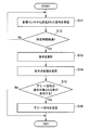
- 5 is a flowchart illustrating an example of an operation of a server according to an embodiment of the present disclosure. It is a flowchart which shows the example of the whole operation
- a plurality of constituent elements having substantially the same or similar functional configuration may be distinguished by adding different numerals after the same reference numerals. However, when it is not necessary to particularly distinguish each of a plurality of constituent elements having substantially the same or similar functional configuration, only the same reference numerals are given.
- similar components in different embodiments may be distinguished by attaching different alphabets after the same reference numerals. However, if it is not necessary to distinguish each similar component, only the same reference numerals are given.
- ⁇ 0. Overview> various techniques are known as techniques for managing an object. For example, a technique for managing livestock as an example of an object is known. Various techniques are disclosed as techniques for managing livestock. For example, a technique for managing livestock using position information by GNSS (Global Navigation Satellite System) has been disclosed (see, for example, JP-A-2008-73005). However, it is desirable to provide a technique that can more easily manage an object.
- GNSS Global Navigation Satellite System
- livestock such as dairy cows may have more than 100 animals or more than 1000 animals. Therefore, it is necessary to manage a plurality of livestock such as dairy cows as a group (group management is necessary).
- group management is necessary.
- a livestock particularly, cattle as livestock
- a management target subject to group management is not limited to livestock.
- the management target subject to group management may be a living organism other than livestock (for example, a human) or an inanimate organism (for example, a moving body such as a robot or a vehicle).
- the herd is in an indoor breeding ground.
- the place where the herd is located is not limited to indoor breeding grounds.
- the herd may be in an outdoor breeding ground.
- the case where a user is a farmer who works with respect to a cow and the case where a user is a veterinarian who examines the state of a cow are mainly assumed.
- the user is not limited to a farmer, and the user is not limited to a veterinarian.
- a farmer identifies a cow in bad condition (for example, health condition) from a herd and tries to work on the identified cow, or asks a veterinarian to identify the identified cow
- bad condition for example, health condition
- you want to call a veterinarian if the state of all the cows included in the herd is displayed on a mobile terminal or the like, the state of all the cows will be displayed very cumbersome, so it is difficult to identify the cows themselves There can be.
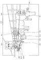
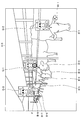
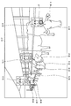
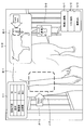
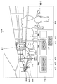
- FIG. 1 is a diagram illustrating a configuration example of a display control system according to an embodiment of the present disclosure.
- the display control system 1 includes a display control device (hereinafter also referred to as “communication terminal”) 10-1 and a display control device (hereinafter also referred to as “communication terminal”) 10-2.
- a server 20 an external sensor 30, wearable devices 40-1 to 40 -N, repeaters 50-1 and 50-2, a gateway device 60, a breeding machine 70, and a network 931. .
- the network 931 is a wireless LAN (Local Area Network)
- the type of the network 931 is not limited as will be described later.
- the relay device 50 relays communication between the wearable device 40 (wearable devices 40-1 to 40-N) and the server 20.
- the number of repeaters 50 is two, but the number of repeaters 50 is not limited to two and may be plural.
- the gateway device 60 connects the network 931 to the repeaters 50 (relay devices 50-1 and 50-2) and the external sensor 30.
- the communication terminal 10-1 is a device used by the farmer K. Farmer K is a breeder who raises cows B-1 to BN (N is an integer of 2 or more).
- the communication terminal 10-1 is connected to the network 931, displays an image (hereinafter also referred to as “icon”) according to the position of the cow present in the field of view of the farmer K, and appropriately communicates with the server 20. By transmitting and receiving necessary information, it is possible to manage cows smoothly by the farmer K.
- the icon may be stored by the communication terminal 10-1, or may be stored by the server 20.
- the communication terminal 10-1 is a device of a type (for example, a glass type or a head-mounted display) that is attached to the farmer K. Assume a case. However, the communication terminal 10-1 may be a device of a type that is not attached to the farmer K (for example, a smartphone, a panel display attached to a wall, etc.). In this specification, it is assumed that the communication terminal 10-1 is a see-through device. However, the communication terminal 10-1 may be a non-see-through device.
- the communication terminal 10-2 is a device used by the veterinarian M.
- Veterinarian M treats an injury or illness of cattle B-1 to BN.
- the communication terminal 10-2 is connected to the network 931 and can perform various types of communication and information sharing with the communication terminal 10-1 used by the farmer K via the server 20.
- the communication terminal 10-2 can make a call with the communication terminal 10-1 used by the farmer K, and can browse a check result list of cattle registered based on the operation of the farmer K. .
- the veterinarian M confirms the necessity of care for the cows of the farmer K by a request by a call from the farmer K or by browsing the check result list, and visits the farm of the farmer K to perform a medical practice.
- the communication terminal 10-2 is a device of a type (for example, a glass type, a head mounted display) that is attached to the veterinarian M. Assume a case. However, the communication terminal 10-2 may be a device of a type that is not attached to the veterinarian M (for example, a smartphone, a panel display attached to a wall, or the like). In the present specification, it is assumed that the communication terminal 10-2 is a see-through device. However, the communication terminal 10-2 may be a non-see-through device.
- the external sensor 30 is a sensor that is not directly attached to the body of the cow B (cow B-1 to BN).
- the external sensor 30 is a monitoring camera
- the external sensor 30 is not limited to the monitoring camera.
- the external sensor 30 may be a camera-mounted drone.
- the external sensor 30 captures an image so as to overlook a part or all of the cow B (cow B-1 to BN) (hereinafter also referred to as “overhead image”).
- the direction of the external sensor 30 is not limited.
- the external sensor 30 is a visible light camera.
- the type of the external sensor 30 is not limited.
- the external sensor 30 may be an infrared thermography camera.
- the external sensor 30 is an infrared thermography camera
- the body surface temperature of the cow can be measured from an image captured by the infrared thermography camera.
- the external sensor 30 may be another type of camera such as a depth sensor that can acquire spatial three-dimensional data.
- An image obtained by the external sensor 30 is transmitted from the external sensor 30 to the server 20 via the gateway device 60 and the network 931.
- the external sensor 30 may include environmental sensors such as an outside air temperature sensor and a humidity sensor in addition to the camera. A value measured by such an environmental sensor is transmitted to the server 20 as a measured value.
- the server 20 is a device that performs various types of information processing for managing the cow B (cow B-1 to cow BN). Specifically, the server 20 includes information associated with individual information (including identification information) of cow B (cow B-1 to cow BN), position information, and wearable device ID (hereinafter referred to as “cow”). It is also referred to as “information”.) Is read out as necessary.
- the identification information may include individual identification information given from the country, an identification number of an IOT (Internet of Things) device, an ID given by the farmer K, and the like.
- the server 20 updates cow information or reads cow information as needed.
- Individual information includes basic information (identification information, name, date of birth, male and female, etc.), health information (length, weight, medical history, treatment history, pregnancy history, health level, breeding history, etc.), activity information ( Exercise amount history, etc.), harvest information (milking amount history, milk components, etc.), status (current situation, information on work required for cattle, etc.), schedule (treatment plan, birth plan, etc.), sensor data log, etc.
- health contents include periodic measurement, abnormality confirmation, estrus confirmation, etc. (in addition, injury confirmation, pregnancy confirmation, physical condition confirmation, etc.) .
- the current situation include the current location (grazing, cowshed, milking, waiting for milking).
- the individual information can be input and updated manually or automatically by the farmer K.
- the farmer K can visually check the state of the cow to determine whether the cow's physical condition is good or bad, and can input the determined cow's physical condition.
- the health status of the server 20 is updated based on whether the cow's physical condition is good or bad inputted by the farmer K.
- the veterinarian M can diagnose a cow and input a diagnosis result.
- the health status of the server 20 is updated based on the diagnosis result input by the veterinarian M.
- the server 20 can estimate the state of the cow.
- the server 20 receives the sensor ID and the sensor data from the wearable device 40 and the external sensor 30, and the processing unit (machine learning control unit) 212 (FIG. 3) processes the sensor data based on a predetermined algorithm or machine.
- the processing unit (machine learning control unit) 212 processes the sensor data based on a predetermined algorithm or machine.
- the state of each cow is estimated.
- the server 20 estimates that a cow whose body temperature has rapidly increased is a plague, or estimates that a cow whose activity has rapidly increased has an estrus sign.
- the server 20 may estimate a state such as estrus from breeding information such as an estrus history so far, and estimates the state by combining sensor data and cow information (data in the database). May be.
- cow information is stored in the server 20.
- the place where the cow information is stored is not limited.
- the cow information may be stored inside a server different from the server 20.
- the cow information may be stored inside the communication terminal 10.
- the wearable device 40 (40-1 to 40-N) includes a communication circuit, a sensor, a memory, and the like, and is worn on the body of the corresponding cow B (cow B-1 to cow BN).
- the sensor may include an activity amount sensor, a body temperature sensor, a meal amount measurement sensor that measures the number of ruminations, or another sensor.
- the wearable device 40 (40-1 to 40-N) may use a secondary battery as a power source, or may drive solar power or self-power generation using vibration power at least in part as a power source. .
- the shape of the wearable device 40 is not particularly limited.
- the wearable device 40 may be a tag type device.
- the wearable device 40 also includes the repeater 50-1, the repeater 50, the identification number of the corresponding IOT device of the cow B, sensor data (for example, information for specifying position information), and the wearable device ID. -2, transmitted to the server 20 via the gateway device 60 and the network 931.
- sensor data for example, information for specifying position information
- wearable device ID. -2 transmitted to the server 20 via the gateway device 60 and the network 931.
- various information is assumed as the information for specifying the position information of the cow B.
- the information for specifying the position information of the cow B is the reception intensity of the wireless signal transmitted from the repeater 50-1 and the repeater 50-2 at each predetermined time in the wearable device 40. including. Then, the server 20 specifies the position information of the wearable device 40 (cow B) based on these received intensities and the position information of the repeaters 50-1 and 50-2. Thereby, in the server 20, it is possible to manage the positional information on the cow B in real time.
- the information for specifying the position information of cow B is not limited to such an example.
- the information for specifying the position information of the cow B is a radio signal received by the wearable device 40 among radio signals transmitted from the repeater 50-1 and the repeater 50-2 every predetermined time. May include identification information of the transmission source relay station.
- the server 20 may specify the position of the relay station identified by the identification information of the transmission source relay station as the position information of the wearable device 40 (cow B).
- the information for specifying the position information of the cow B may include the arrival time (difference between the transmission time and the reception time) of the signal received from each GPS (Global Positioning System) satellite by the wearable device 40. Moreover, in this specification, although the case where the positional information on the cow B is specified in the server 20 is mainly assumed, the positional information on the cow B may be specified in the wearable device 40. In such a case, the position information of the cow B may be transmitted to the server 20 instead of the information for specifying the position information of the cow B.
- GPS Global Positioning System
- the information for specifying the position information of the cow B may be a bird's-eye view image obtained by the external sensor 30.
- the server 20 may specify the position of the pattern of the cow B recognized from the overhead image obtained by the external sensor 30 as the position information of the cow B. Is possible.
- identification information for example, an identification number of an IOT device
- the wearable device 40 also includes a proximity sensor, and when the wearable device 40 approaches a specific facility, the proximity sensor can detect the specific facility. The behavior of the cow can be automatically recorded by recording the position information of the wearable device 40 and the information related to the facility that the wearable device 40 approaches.
- a proximity sensor is provided at a place where milking is performed as an example of a specific facility, and the wearable device 40 having a proximity sensor communicated with the proximity sensor is associated with a milking record by an automatic milking machine. If so, it can also record which cows and how much milk they produced.
- the breeding machine 70 is a machine used for cattle breeding.
- the breeding machine 70 may be various robots such as an automatic feeder (feeder), an automatic milking machine, and an automatic barn cleaner.
- the breeding machine 70 can change the amount of feeding, change the necessity of milking, or change the frequency of cleaning in accordance with an instruction command from the server 20 or the communication terminal 10.
- the automatic milking machine can measure milk components, and the measurement result can be handled as a part of external sensor data.
- FIG. 2 is a block diagram illustrating a functional configuration example of the communication terminal 10 according to the embodiment of the present disclosure.
- the communication terminal 10 includes a control unit 110, a detection unit 120, a communication unit 130, a storage unit 150, and an output unit 160.
- these functional blocks provided in the communication terminal 10 will be described.
- the communication terminal 10 when the communication terminal 10 includes a housing that can be mounted on the head of the farmer K, the housing may include these functional blocks.
- the functional configuration example of the communication terminal 10-1 used by the farmer K will be mainly described.
- the functional configuration of the communication terminal 10-2 used by the veterinarian M is also the communication terminal 10-1 used by the farmer K. It can be realized in the same manner as the functional configuration.
- the control unit 110 executes control of each unit of the communication terminal 10-1.
- the control unit 110 may be configured by a processing device such as one or a plurality of CPUs (Central Processing Units).
- a processing device such as a CPU
- the processing device may be configured by an electronic circuit.
- the control unit 110 includes a display control unit 111, a selection unit 112, a determination unit 113, and a process control unit 114. These blocks included in the control unit 110 will be described in detail later.
- the detection unit 120 includes one or a plurality of sensors, and can detect a direction in which the farmer K is interested in the three-dimensional space (hereinafter, also simply referred to as “attention direction”).
- a direction in which the farmer K is interested in the three-dimensional space hereinafter, also simply referred to as “attention direction”.
- the direction of the face of the farmer K (the position of the field of view of the farmer K) is used as the attention direction will be mainly described.
- the direction of the face of the farmer K may be detected in any way.
- the face direction of the farmer K may be the direction of the communication terminal 10-1.
- the orientation of the communication terminal 10-1 may be detected by a ground axis sensor or a motion sensor.
- the detection unit 120 can detect the direction indicated by the farmer K in the three-dimensional space (hereinafter also simply referred to as “instruction direction”).
- instruction direction the direction indicated by the farmer K in the three-dimensional space
- the line of sight of the farmer K may be detected in any way.
- the detection unit 120 includes an image sensor
- the line of sight of the farmer K may be detected based on an eye region that appears in an image obtained by the image sensor.
- the attention direction or the instruction direction may be detected based on the detection result by the motion sensor that detects the movement of the farmer K (even if the instruction direction preceding the position in the three-dimensional space detected by the motion sensor is detected). Good).
- the motion sensor may detect acceleration with an acceleration sensor, or may detect angular velocity with a gyro sensor (for example, a ring-type gyro mouse).
- the attention direction or the indication direction may be detected based on a detection result by the tactile-type device.
- An example of a tactile sensation device is a pen-type tactile sensation device.
- the attention direction or the instruction direction may be a direction indicated by a predetermined object (for example, a direction indicated by the tip of the bar) or a direction indicated by the finger of the farmer K.
- the direction indicated by the predetermined object and the direction indicated by the finger of the farmer K may be detected based on the object and the finger appearing in the image obtained by the image sensor when the detection unit 120 includes the image sensor.
- the attention direction or the instruction direction may be detected based on the face recognition result of the farmer K.
- the detection unit 120 includes an image sensor
- the center position between both eyes may be recognized based on an image obtained by the image sensor, and a straight line extending from the center position between both eyes may be detected as the indication direction.
- the attention direction or the instruction direction may be a direction corresponding to the utterance content of the farmer K.
- the detection unit 120 includes a microphone
- the direction corresponding to the utterance content of the farmer K may be detected based on a voice recognition result for sound information obtained by the microphone.
- a voice recognition result for sound information obtained by the microphone.
- an utterance expressing the depth of the field of view for example, utterance such as “back cow”
- text data “back cow” is obtained as a speech recognition result for the utterance
- the pointing direction with the depth of view ahead can be detected based on the text data “back cow”.
- the content of the utterance may be “show an overhead image”, “show from above”, “show cow in the back”, or the like.
- the detection unit 120 can detect various operations by the farmer K.
- various operations by the farmer K may be detected in any way.
- various operations by farmer K may be hands-free operations (operations using non-contact sensors).
- detection unit 120 preferably includes a non-contact sensor).
- the non-contact sensor may detect at least one of the gesture of the farmer K, the line of sight of the farmer K, and the voice recognition result (farmer voice command of the farmer K).
- the gesture of farmer K may include the movement of farmer K.
- the movement of the farmer K may be detected in any way.
- the detection unit 120 includes an image sensor
- the movement of the farmer K may be detected from an image obtained by the image sensor.
- the movement of the farmer K may be a predetermined movement such as blinking, holding an open hand, or a virtual tap gesture.
- the detection unit 120 may detect the movement of the farmhouse K using a motion sensor.
- the motion sensor may detect acceleration with an acceleration sensor or may detect angular velocity with a gyro sensor.
- the gesture of the farmer K may include the position of the farmer K's body (for example, the position of the head) or the position of the farmer K (for example, the posture of the whole body).
- various operations by the farmer K may be detected by myoelectricity (for example, myoelectricity of the jaw, myoelectricity of the arm, etc.) or may be detected by an electroencephalogram.
- various operations performed by the farmer K include operations on switches, levers, buttons, and the like provided on the communication terminal 10-1 or a controller connected to the communication terminal 10-1 by wire or wirelessly, and touching the communication terminal 10-1. Operation by a contact type sensor such as operation may be used.
- the detection unit 120 can detect the position information of the communication terminal 10-1 in addition to the direction of the communication terminal 10-1.
- the position information of the communication terminal 10-1 may be detected in any way.
- the position information of the communication terminal 10-1 may be detected based on the arrival time (difference between the transmission time and the reception time) of the signal received from each GPS satellite by the communication terminal 10-1.
- the communication terminal 10-1 can receive radio signals transmitted from the repeater 50-1 and the repeater 50-2 in the same manner as the wearable devices 40-1 to 40-N, the wearable device 40-
- the position information of the communication terminal 10-1 can be detected in the same manner as the position information of 1 to 40-N.
- the position information of the communication terminal 10-1 may be relative position information of an HMD (Head Mounted Display) measured by a positioning sensor such as an SLAM (Simultaneous Localization and Mapping) camera. Further, the position information of the communication terminal 10-1 may be position information corrected (offset) based on the mounting position of the HMD.
- HMD Head Mounted Display
- SLAM Simultaneous Localization and Mapping
- the communication unit 130 includes a communication circuit, and has a function of communicating with other devices via the network 931 (FIG. 1).
- the communication unit 130 is configured by a communication interface.
- the communication unit 130 can communicate with the server 20 via the network 931 (FIG. 1).
- the storage unit 150 includes a memory, and is a recording device that stores a program executed by the control unit 110 and stores data necessary for executing the program.
- the storage unit 150 temporarily stores data for calculation by the control unit 110.
- the storage unit 150 may be a magnetic storage unit device, a semiconductor storage device, an optical storage device, or a magneto-optical storage device.
- the output unit 160 outputs various types of information.
- the output unit 160 may include a display capable of performing display visible to the farmer K, and the display may be a liquid crystal display (the liquid crystal display is light transmissive according to voltage).
- an organic EL (Electro-Luminescence) display (the organic EL display is configured to include an organic substance that emits light by a predetermined voltage).
- the output unit 160 may include an audio output device such as a speaker (the audio output device includes a coil, a magnet, and a diaphragm).
- the output unit 160 may include a tactile presentation device that presents the farmer K with a tactile sensation (the tactile presentation device includes a vibrator that vibrates with a predetermined voltage).
- the display is a device (for example, an HMD) that can be attached to the head of the farmer K.
- the output unit 160 includes a housing that can be mounted on the head of the farmer K
- the housing may include a display that displays information about cows.
- the display may be a transmissive display or a non-transmissive display.
- the display is a non-transmissive display, the farmer K can visually recognize the space corresponding to the field of view by displaying the image captured by the image sensor included in the detection unit 120.
- FIG. 3 is a block diagram illustrating a functional configuration example of the server 20 according to the embodiment of the present disclosure.
- the server 20 includes a control unit 210, a storage unit 220, and a communication unit 230.
- these functional blocks included in the server 20 will be described.
- the control unit 210 controls each unit of the server 20.
- the control unit 210 may be configured by a processing device such as one or a plurality of CPUs (Central Processing Units).
- a processing device such as a CPU
- the processing device may be configured by an electronic circuit.
- the control unit 210 includes an information acquisition unit 211, a processing unit (machine learning control unit) 212, and an information providing unit 213. These blocks included in the control unit 210 will be described in detail later.
- the storage unit 220 includes a memory, and is a recording device that stores a program executed by the control unit 210 and stores data (for example, cow information) necessary for executing the program.
- the storage unit 220 temporarily stores data for calculation by the control unit 210.
- the storage unit 220 may be a magnetic storage unit device, a semiconductor storage device, an optical storage device, or a magneto-optical storage device.
- the communication unit 230 includes a communication circuit, and has a function of communicating with other devices via the network 931 (FIG. 1).
- the communication unit 230 is configured by a communication interface.
- the communication unit 230 communicates with the communication terminal 10, the external sensor 30, the wearable device 40 (wearable devices 40-1 to 40-N), and the breeding machine 70 via the network 931 (FIG. 1). Communication is possible.
- FIG. 4 is a block diagram illustrating a functional configuration example of the external sensor 30 according to the embodiment of the present disclosure.
- the external sensor 30 includes a control unit 310, a detection unit 320, a communication unit 330, and a storage unit 350.
- these functional blocks provided in the external sensor 30 will be described.
- the control unit 310 executes control of each unit of the external sensor 30.
- the control unit 310 may be configured by a processing device such as one or a plurality of CPUs (Central Processing Units).
- the control unit 310 may be configured by a processing device such as a CPU, the processing device may be configured by an electronic circuit.
- the detection unit 320 includes one or a plurality of sensors.
- the detection unit 320 is configured to include an image sensor, and obtains a bird's-eye view image by imaging a part or all of the cow B (cow B-1 to BN).
- the direction of the image sensor is not limited.
- the detection unit 320 may include environmental sensors such as an outside air temperature sensor and a humidity sensor.
- the communication unit 330 includes a communication circuit, and has a function of performing communication with other devices via the network 931 (FIG. 1).
- the communication unit 330 is configured by a communication interface.
- the communication unit 330 can communicate with the server 20 via the network 931 (FIG. 1).
- the storage unit 350 includes a memory, and is a recording device that stores a program executed by the control unit 310 and stores data necessary for executing the program.
- the storage unit 350 temporarily stores data for calculation by the control unit 310.
- the storage unit 350 may be a magnetic storage unit device, a semiconductor storage device, an optical storage device, or a magneto-optical storage device.
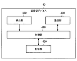
- FIG. 5 is a block diagram illustrating a functional configuration example of the wearable device 40 according to the embodiment of the present disclosure.
- the wearable device 40 includes a control unit 410, a detection unit 420, a communication unit 430, and a storage unit 450.
- these functional blocks included in the wearable device 40 will be described.
- the control unit 410 executes control of each unit of the wearable device 40.
- the control unit 410 may be configured by a processing device such as one or a plurality of CPUs (Central Processing Units).
- CPUs Central Processing Units
- the processing device may be configured by an electronic circuit.
- the detection unit 420 includes one or more sensors.
- the detection unit 420 may include an activity amount sensor.
- the activity amount sensor includes an acceleration sensor, and may detect the activity amount based on the acceleration detected by the acceleration sensor.
- the detection part 420 may have a body temperature sensor.
- the detection part 420 may have a meal amount measurement sensor.
- the meal amount measuring sensor may include a vibration sensor and measure the number of ruminations based on the number of vibrations detected by the vibration sensor.
- the communication unit 430 includes a communication circuit, and has a function of performing communication with other devices via the network 931 (FIG. 1).
- the communication unit 430 is configured by a communication interface.
- the communication unit 430 can communicate with the server 20 via the network 931 (FIG. 1).
- the storage unit 450 includes a memory, and is a recording device that stores a program executed by the control unit 410 and stores data necessary for executing the program. Storage unit 450 temporarily stores data for calculation by control unit 410. Note that the storage unit 450 may be a magnetic storage unit device, a semiconductor storage device, an optical storage device, or a magneto-optical storage device.
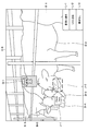
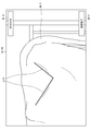
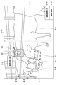
- FIG. 6 is a diagram illustrating an example of display by the communication terminal 10-1 used by the farmer K.
- the field of view V-1 of the farmer K is shown.
- the visual field V-1 may simply be the field of view of the farmer K itself, may be a range corresponding to a captured image of a sensor (for example, a camera) of the detection unit 120, or can be viewed through a transmissive / non-transmissive display. It may be an area.
- a herd of cattle (cow B-1 to B-8) is present in an indoor breeding yard, and a view of farmer K V-1 shows a herd of cattle (cow B-1 to B- 8) exists.
- the number of cows included in the herd is not particularly limited.
- the communication terminal 10-1 worn by the farmer K when the detection unit 120 detects the state of the communication terminal 10-1 (for example, position information and orientation information), the communication unit 130 The state (position information and direction) is transmitted to the server 20.
- the information acquisition unit 211 determines the state (position information and orientation) of the communication terminal 10-1 and the cow B -1 to BN, based on the position information of each of the communication terminals 10-1 (farm K), and a predetermined distance based on the direction of the communication terminal 10-1
- a herd of cattle (cow B-1 to BM) (M is an integer of 2 or more) existing in the angle range (field of view K-1 of farmer K) is determined.
- the distance between the position of the communication terminal 10-1 (farm K) and the positions of the cows B-1 to BN may be calculated by other methods. For example, when the communication terminal 10-1 can receive a radio signal transmitted from the wearable device 40 (wearable devices 40-1 to 40-M), the determination unit 113 determines that the wearable device 40-1 to Based on the reception intensity of the radio signal transmitted from 40-M, the distance between the position of the communication terminal 10-1 (farm K) and the positions of the cows B-1 to BN may be calculated. Alternatively, the distance between the position of the communication terminal 10-1 (farm K) and the position of each of the cows B-1 to BN is the depth information obtained from the image captured by the image sensor of the communication terminal 10-1. Based on this, it may be acquired as relative position information.
- the herd (cattle B-1 to BM) is a part of the cattle B-1 to BN managed by the server 20.
- B-1 to BM) may be all of cows B-1 to BN (M may be N).
- M may be N.
- the information acquisition unit 211 stores the cows (cow B-1 ⁇ BN) to determine the herd (cattle B-1 to B-8).
- the information acquisition unit 211 acquires the individual information and the position information of each herd (cattle B-1 to B-8)
- the information providing unit 213 reads each herd (cattle B-1 to B-8). Is provided to the communication terminal 10-1 via the communication unit 230.
- communication unit 130 receives individual information and position information of each herd (cow B-1 to B-8).
- the display control unit 111 acquires the status of each cow group (cow B-1 to B-8) from the individual information of each cow group (cow B-1 to B-8).
- periodic measurement, abnormality confirmation, and estrus confirmation are assumed as the state of each herd (cow B-1 to B-8).
- the state of each of the herds (cow B-1 to B-8) is not limited to a predetermined state such as periodic measurement, abnormality confirmation, and estrus confirmation.
- the state of cow B-1 is estrus confirmation
- the state of cow B-2 is abnormality confirmation
- the state of cow B-7 is regular measurement.
- the regular measurement indicates a state where the current measurement should be performed when the cow's BCS (body condition score) is regularly measured. For example, if the measurement interval is one month, cows that have passed one month from the previous measurement date registered in the cow information (database) are subject to regular measurement. Abnormality confirmation indicates a state in which poor health such as illness or injury is estimated. Estrus confirmation indicates a state in which there is an estrus sign and estrus is estimated.
- the display control unit 111 has a predetermined positional relationship between the position of the cow B-1 and the icon G-2 corresponding to the state “estrus confirmation” of the cow B-1 existing in the field of view V-1 of the farmer K. Control to be displayed at the position. If the icon G-2 corresponding to the state “estrus confirmation” is displayed at a position having a predetermined positional relationship with the position of the cow B-1, the icon G-2 corresponding to the state “estrus confirmation” and the cow B ⁇ It is possible to intuitively understand that 1 corresponds.
- the display control unit 111 corresponds to the state type “estrus confirmation” category of the cow B-1.
- the display of the icon G-2 may be controlled.
- display at a position depending on the position of an object existing in the field of view is also referred to as “AR display”.
- the display control unit 111 recognizes the position of the head of the cow B-1.
- An example is shown in which control is performed so that the icon G-2 is displayed above the head of the cow B-1 by recognizing by processing or the like.
- the position where icon G-2 is displayed is not limited.
- the display control unit 111 may use the position information of the cow B-1 for recognizing the head position of the cow B-1, or may be detected by the detection unit 120 in addition to the position information of the cow B-1. The head position of cow B-1 recognized from the image may be used.
- the display control unit 111 may display the icon G-2 at a position a predetermined distance above the position indicated by the position information of the cow B-1, or the icon G- 2 may be displayed.
- the display control unit 111 may display the icon G-2 at a position away from the cow B-1 by a predetermined distance and display an anchor that connects the icon G-2 and the cow B-1. With this anchor, the farmer K can intuitively grasp that the icon G-2 corresponds to the cow B-1.
- the display control unit 111 has a predetermined positional relationship between the position of the cow B-2 and the icon G-1 corresponding to the state “abnormal confirmation” of the cow B-2 existing in the field of view V-1 of the farmer K. Control to be displayed at the position. If icon G-1 corresponding to state “abnormality confirmation” is displayed at a position having a predetermined positional relationship with the position of cow B-2, icon G-1 corresponding to state “abnormality confirmation” and cow B- It is possible to intuitively grasp that 2 corresponds.
- the display control unit 111 corresponds to the state type “abnormality confirmation” category of the cow B-2.
- the display of the icon G-1 may be controlled.
- the display control unit 111 shows that the icon G-3 corresponding to the state “periodic measurement” of the cow B-7 existing in the field of view V-1 of the farmer K has a predetermined positional relationship with the position of the cow B-7. Control to be displayed at the position. If the icon G-3 corresponding to the state “periodic measurement” is displayed at a position having a predetermined positional relationship with the position of the cow B-7, the icon G-3 corresponding to the state “periodic measurement” and the cow B- It is possible to grasp intuitively that 7 corresponds. For example, when the state type (state category) “periodic measurement” and the icon G-3 are associated in advance, the display control unit 111 corresponds to the state type “periodic measurement” category of cow B-7. The display of the icon G-3 may be controlled.
- the positions where the icons G-1 and G-3 are displayed may be controlled in the same manner as the positions where the icon G-2 is displayed. That is, the positional relationship between the cow B and the icon G may be constant regardless of the type (state type) of the icon G. Then, the farmer K can easily grasp the correspondence between the cow B and the icon G regardless of the type of the icon G. However, the position of the icon G may be changed according to the type of the icon G (state type).
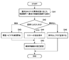
- the display control unit 111 performs control so that an icon is displayed for cattle satisfying the first condition among the herd (cow B-1 to B-8). You may restrict
- the display control unit 111 performs control so that icons are displayed for cows in a predetermined state (in the example shown in FIG. 6, cows B-1, B-2, and B-7). If there is a cow in a state other than this state (in the example shown in FIG. 6, cows B-3 to B-6, B-8), the icon display of the cow may be restricted (the icon is not displayed) You may do it). As another example, as will be described with reference to FIG. 7, the display control unit 111 controls the icon display according to the state where the display is selected, and displays the icon display according to the state where the non-display is selected. It may be limited (the icon may not be displayed).
- FIG. 7 is a diagram showing a first modification of display by the communication terminal 10-1 used by the farmer K.
- FIG. 6 shows an example in which an icon G-2 corresponding to the state “estrus confirmation”, an icon G-1 corresponding to the state “abnormality confirmation”, and an icon G-3 corresponding to the state “periodic measurement” are all displayed. showed that.
- the icons G-1 to G-3 may be switchable between display and non-display for each state. Then, the farmer K can visually recognize only the icon G corresponding to the state to be confirmed.
- the icon G-1 corresponding to the state “abnormality confirmation” and the icon G ⁇ corresponding to the state “estrus confirmation” are displayed.
- the icon G-3 corresponding to the state “periodic measurement” may be hidden.
- the field of view V-2 of the farmer K is shown. In the field of view V-2, the icon G-3 corresponding to the state “periodic measurement” is not displayed.
- the display control unit 111 may control the display of information indicating the display or non-display of the icons G-1 to G-3 for each state (hereinafter also referred to as “display / non-display”).
- FIG. 7 shows display / non-display H-1 of icon G-1, display / non-display H-2 of icon G-2, and display / non-display H-3 of icon G-3.
- the display / non-display H-1 of the icon G-1 and the display / non-display H-2 of the icon G-2 are This is indicated by a mode of display (for example, white).
- the display / non-display H-3 of the icon G-3 is indicated by a mode (for example, black) indicating non-display.
- the display modes of the display and non-display of the icons G-1 to G-3 are not limited.
- Switching between displaying and hiding the icons G-1 to G-3 may be performed by the display control unit 111 when the detecting unit 120 detects a switching operation by the farmer K.
- the variation of the switching operation is as described above.
- the farmer K indicates the indication direction (for example, the line of sight of the farmer K) to the display / non-display H-3 of the icon G-3.
- the display control unit 111 indicates that the display / non-display H-3 of the icon G-3 exists in the direction indicated by the farmer K detected by the detection unit 120. Judgment is made, and the icon G-3 corresponding to the state “periodic measurement” is hidden.
- the display control unit 111 displays the pointer P at the position where the designated direction of the farmer K is applied, as shown in FIG. It is good to control it.
- the farmer K may apply a direction of interest (for example, the direction of the face of the farmer K) to the display / non-display of the icon G-3.
- a direction of interest for example, the direction of the face of the farmer K
- the display control unit 111 displays the non-display H-3 of the icon G-3 at the position where the attention direction detected by the detection unit 120 is applied.
- the icon G-3 corresponding to the state “periodic measurement” may be hidden by determining that it exists.
- the display control unit 111 may perform control so that the pointer is displayed at a position where the attention direction of the farmer K is applied.
- the attention direction eg, the direction of the face of the farmer K
- the display control unit 111 may perform control so that the pointer is displayed at a fixed position (for example, the center of the visual field V-2).
- switching from the display of the icon G-3 to the non-display has been mainly described.
- switching from non-display to display of the icon G-3 may be realized in the same manner as switching from display to non-display of the icon G-3.
- the display / non-display switching of the icon G-1 and the icon G-2 may be realized similarly to the switching from the display of the icon G-3 to the non-display.
- the display control unit 111 may control the display of an icon corresponding to the state of the cow when the state of the cow corresponds to the position of the farmer K or the behavior of the farmer K.
- the position information of the communication terminal 10-1 may be obtained based on the sensor data detected by the detection unit 120 as described above.
- the behavior information of the farmer K may be obtained based on sensor data detected by the detection unit 120, or based on sensor data detected by sensors provided in various facilities, as will be described later. May be obtained.
- Farmer K may not want to see the icon, especially when it is in the office. That is, no icon corresponds to the position “office” where the farmer K exists. Therefore, the display control unit 111 may not display the icon when the farmer K exists in the office.
- the display control unit 111 may control the display of the icon G-2 corresponding to the state “estrus confirmation” when the farmer K exists in the barn.
- the display control unit 111 may control the display of the icon G-3 according to the state “periodic measurement” when the farmer K exists in the barn.
- farmer K may have different icons he wants to see when feeding and when milking. That is, when the behavior of the farmer K is “feeding”, the display control unit 111 may control the display of an icon corresponding to the behavior “feeding”. On the other hand, when the action of the farmer K is “milking”, the display control unit 111 may control the display of an icon corresponding to the action “milking”. For example, if the farmer K is detected by a sensor provided in the feeding tractor, it can be determined that the farmer K's action is “feeding”. Moreover, if the farmer K is detected by the proximity sensor provided in the place where milking is performed, it can be determined that the action of the farmer K is “milking”.
- the display control unit 111 selects a predetermined state from a plurality of states based on the priority of each of the plurality of states, and displays an icon corresponding to each of the predetermined states. You may control. For example, the display control unit 111 may select a state in which the priority exceeds a threshold value from a plurality of states, and may control display of an icon corresponding to the selected state.
- the priority of each state is not limited, but the priority of the state “abnormality confirmation” may be the highest, the priority of the state “estrus confirmation” may be the second highest, and the priority of the state “periodic measurement” may be the lowest.
- the display control unit 111 selects a predetermined state from the plurality of cow states based on the priority of each of the plurality of cow states, and displays icons corresponding to the predetermined states.
- the display may be controlled. For example, the display control unit 111 may select a state in which the priority level exceeds a threshold value from the states of each of the plurality of cows, and may control display of an icon corresponding to the selected state.
- priority type information such as “priority” and “non-priority” is set for each state, and an icon is displayed only for the cow corresponding to the state where the priority information is “priority”. It may be displayed.
- the display control unit 111 may perform control so that the number of cows whose icons are not displayed is displayed for each state.
- FIG. 8 is a diagram showing a second modification of the display by the communication terminal 10-1 used by the farmer K.
- the icon G-2 corresponding to the state “estrus confirmation”, the icon G-1 corresponding to the state “abnormality confirmation”, and the icon G-3 corresponding to the state “periodic measurement” all communicate with the cow.
- An example is shown in which the same size is displayed regardless of the distance to the terminal 10-1.
- the display control unit 111 displays the icon G depending on the size according to the distance between the cow and the farmer K (that is, the communication terminal 10-1). It is preferable to control so that -1 to G-3 are displayed.
- the size according to the distance between the cow and the communication terminal 10-1 is the size according to the distance between the icon virtually arranged in the AR space according to the position of the cow and the communication terminal 10-1. It's okay.
- a view V-3 of the farmer K is shown.
- the display control unit 111 controls the icon G to be displayed smaller as it is farther from the communication terminal 10-1 (the icons G-3, the icons G-1, and the icons in ascending order).
- G-2 is controlled to be displayed).
- the display control unit 111 may control the display of icons according to the state according to the display mode according to the priority of the cow state.
- the display control unit 111 sets the display mode of an icon corresponding to a state in which the priority is higher than the reference priority (for example, the icon G-1 corresponding to the state “abnormality confirmation”) to which the priority is It may be different from the display mode of an icon corresponding to a state lower than the reference priority (for example, icon G-2 corresponding to the state “estrus confirmation”, icon G-3 corresponding to the state “periodic measurement”, etc.). (The color may be changed as shown in FIG. 8).
- the display mode may be changed in any way.
- the display control unit 111 may make an icon corresponding to a state in which the priority is higher than the reference priority easier to stand out by adding a motion (such as bouncing).
- FIG. 9 is a diagram showing a third modification of display by the communication terminal 10-1 used by the farmer K.
- a view V-4 of the farmer K is shown.
- the pointer P exists at the position of the icon G-3.
- the display control unit 111 may enlarge the icon G-3. Then, the visibility of the icon G-3 is improved. In this way, the display control unit 111 may enlarge the icon G when the pointer P is present at the position of the icon G or at a position close to the icon G.
- the icon G displayed in this way may be selectable.
- the selection of the icon G may be performed by the selection unit 112 when the selection operation by the farmer K is detected by the detection unit 120 in the communication terminal 10-1.
- the variation of the selection operation is as described above.
- FIG. 10 is a diagram for explaining an example of selection of the icon G-1 corresponding to the state “abnormal confirmation”.
- a view V-5 of the farmer K is shown.
- the selection unit 112 determines that the icon G-1 is present in the direction indicated by the farmer K detected by the detection unit 120, and enters the state “abnormal confirmation”.
- the corresponding icon G-1 is selected.
- the display control unit 111 may control the pointer P to be displayed at a position where the direction indicated by the farmer K (for example, the line of sight of the farmer K) is applied. That is, the selection unit 112 may select the icon G when the selection operation is performed in a state where the pointer P is present at the position of the icon G or a position close to the icon G. Further, as described above, instead of the direction indicated by the farmer K, the pointer P may be controlled to be displayed at a position where the farmer's attention direction (for example, the direction of the farmer K's face) is applied. .
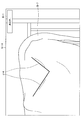
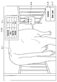
- FIG. 11 is a diagram showing an example of the field of view of the farmer K after selection of the icon G-1 corresponding to the state “abnormality confirmation”.
- the display control unit 111 guides the farmer K to visually confirm the confirmation location corresponding to the state “abnormal confirmation” in the cow B-2. Control the guidance display.
- the farmer K selects an icon corresponding to the state of the cow, the farmer K is guided to visually check the confirmation location corresponding to the state of the cow, so that the cow can be managed more easily.
- the confirmation location For example, when farmer K wants to work only on cattle that require confirmation, it is possible to grasp the confirmation location by looking only at the cattle with the icon displayed, and make necessary communications. Is possible.
- the farmer K can identify the cow that needs to be confirmed by the icon, and can naturally move the line of sight from the icon to the confirmation location, thereby reducing the operation burden on the farmer K.
- the confirmation location may exist in the field of view of Farmer K or may not exist in the field of view of Farmer K.
- the display control unit 111 may control the highlighted display for the confirmation location as a guidance display.
- the display control unit 111 uses the confirmation place “nose” as a guidance display for guiding the farmer K to visually recognize the confirmation place “nose”. What is necessary is just to control the emphasis display (for example, AR display) with respect to "nose”.
- the highlighting is not particularly limited. In the example shown in FIG. 11, highlighting is performed by an arrow J-1 that points to the confirmation location “nose” and a broken line J-2 that surrounds the confirmation location “nose”.
- the information acquisition unit 211 determines that the body temperature of the cow B-2 has risen beyond a predetermined value in a predetermined period (for example, a short period of 2 to 3 hours).
- a predetermined period for example, a short period of 2 to 3 hours.
- a state of 2 assume a case where it is estimated that a cold has been caught.
- cow B-2's symptoms of nasal discharge are confirmed, it is highly likely that cow B-2 has had a cold.
- the farmer K confirms the state of the nose of the cow B-2 when the server 20 estimates that the cow B-2 has caught a cold. Therefore, when it is estimated that the cow 20 has caught a cold in the server 20, in the communication terminal 10-1, when the detection unit 120 has an image sensor, the display control unit 111 It is preferable to recognize the nose of cow B-2 from the image obtained by the above and highlight the nose as a confirmation location.
- the confirmation location corresponding to the state “abnormality confirmation” is not limited to the nose, and the confirmation location may vary depending on the type of abnormal state.
- the information acquisition unit 211 determines the state of the cow B-2 as the state of the cow B-2 based on the fact that the activity amount of the cow B-2 has decreased beyond a predetermined value in a predetermined period (for example, a short period). Assume that you suspect that your foot was injured. In such a case, it is desirable for the farmer K to check the state of the foot of the cow B-2. Therefore, it is preferable that the display control unit 111 recognizes the foot of the cow B-2 from the image obtained by the image sensor and highlights the foot as a confirmation point.
- the information acquisition unit 211 estimates that the state of feces should be confirmed as the state of cow B-2. In such a case, it is desirable for the farmer K to check the anal condition of the cow B-2. Therefore, the display control unit 111 may recognize the anus of the cow B-2 from the image obtained by the image sensor, and perform highlighting on the anus as a confirmation location.
- the information acquisition unit 211 estimates that there is a suspicion of mastitis as the state of the cow B-2 based on the milk component measurement result by the automatic milking machine (an example of the breeding machine 70). Suppose. In such a case, it is desirable for farmer K to check the breast of cow B-2.
- the display control unit 111 may recognize the breast of the cow B-2 from the image obtained by the image sensor and perform highlighting on the breast as a confirmation location.
- an icon corresponding to the state of the cow is displayed in the vicinity of the cow (for example, on the head of the cow). Moreover, the confirmation location according to the state of the cow corresponding to the selected icon among the displayed icons is highlighted by the AR display. Therefore, according to the embodiment of the present disclosure, when the farmer K confirms the confirmation portion by viewing the highlight after selecting the icon, the amount of movement of the farmer K's line of sight is reduced, and the cognitive burden of the farmer K is reduced. The effect that it becomes possible is enjoyed.
- a list of cows requiring confirmation is displayed on the smartphone, and a schematic diagram showing the confirmation location is displayed on the smartphone at a position away from the list. In such a case, at least one hand of the farmer K is blocked, and the line-of-sight movement amount of the farmer K increases. The work burden on Farmer K is not reduced.
- the display control unit 111 may perform highlighting on each of a plurality of confirmation locations corresponding to the state “abnormality confirmation”.
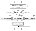
- the process control unit 114 may control the execution of the process.
- the process controlled by the process control unit 114 is not particularly limited.
- the process controlled by the process control unit 114 includes a video call start process with another device, a process of adding the identification information of the cow B-2 corresponding to the state “abnormal confirmation” to the abnormality confirmation list, and It may include at least one of processes for adding information indicating that there is no abnormality in the state “abnormality confirmation” of cow B-2.
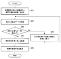
- the detection that the confirmation of the confirmation part is completed may be the detection of the selection operation by the farmer K.
- the display control unit 111 controls the display of the contact button L-1, the list addition button L-2, and the no abnormality button L-3 to the veterinarian.
- the farmer K confirms the confirmation location indicated by the highlighting
- the farmer K performs a selection operation on any of the contact button L-1, the list addition button L-2, and the no abnormality button L-3.
- the process control unit 114 may select a process based on the selection operation by the farmer K and control the execution of the selected process.
- the communication unit 130 may transmit confirmation result input data corresponding to the confirmation result to the server 20.
- the confirmation result input data transmitted by the communication unit 130 may be stored in association with the identification information report of the cow B-2 by the storage unit 220 in the server 20.
- the processing control unit 114 may start a video call with the communication terminal 10-2 used by the veterinarian M.
- a conversation between the farmer K and the veterinarian M is started by video call.
- the processing control unit 114 may start a video call with the communication terminal 10-2 used by the veterinarian M.
- a conversation between the farmer K and the veterinarian M is started by video call.
- the processing control unit 114 automatically activates the image sensor included in the detection unit 120 during the video call, and the image (video) captured by the image sensor is transmitted to the communication terminal 10-2 used by the veterinarian M.
- the communication unit 130 may be controlled so as to be transmitted. By doing so, the farmer K can also have the veterinarian M see the confirmed part of the cow B-2 in real time, so that the veterinarian M can make a more accurate diagnosis.
- the processing control unit 114 displays flag information indicating that the veterinarian has been contacted as an example of confirmation result input data.
- the communication unit 130 may be controlled so as to be transmitted to 20.
- the storage unit 220 may store the flag information in association with the identification information of the cow B-2.
- the processing control unit 114 may control the communication unit 130 such that audio and video during a video call are transmitted to the server 20 together with a call history (call start time and the like).
- the storage unit 220 may store them in association with the identification information of the cow B-2.
- the processing control unit 114 may control the communication unit 130 so that flag information indicating a diagnosis necessary is transmitted to the server 20 as an example of the confirmation result input data.
- the server 20 when flag information indicating a diagnosis required is received by the communication unit 230, the storage unit 220 may store the flag information in association with the identification information of the cow B-2. Then, in the communication terminal 10-2 used by the veterinarian M, a mark indicating that the flag information indicating the diagnosis is required can be AR-displayed based on the position of the cow B-2.
- the processing control unit 114 transmits flag information indicating diagnosis necessary to the server 20 as an example of confirmation result input data.
- the communication unit 130 may be controlled as described above. Then, even if urgent treatment for the cow B-2 is unnecessary, it is possible for the veterinarian M to see the cow B-2 when visiting the farmer K later.
- the flag information may be 0 (no diagnosis required) / 1 (need diagnosis), or may be time information such as the current date (for example, date).
- the flag information indicating the diagnosis required may be stored in the storage unit 220 in association with the identification information of the cow B-2. Then, in the communication terminal 10-2 used by the veterinarian M, a mark indicating that the flag information indicating the diagnosis is required can be AR-displayed based on the position of the cow B-2. When the veterinarian M later visits the farmer K, the veterinarian M can efficiently perform medical care based on the abnormality confirmation list (identification information of the cow with flag information indicating diagnosis required) and the AR display. .
- the cow B- A second diagnosis may be necessary.
- the farmer K may perform a selection operation on the list addition button L-2.
- the processing performed when the selection operation by the farmer K for the list addition button L-2 is detected by the detection unit 120 is as described above.
- the display control unit 111 may control display of an imaging start button (not shown) for starting imaging of a still image or a moving image by the image sensor included in the communication terminal 10-1 of the farmer K. Then, when the selection operation by the farmer K with respect to the imaging start button (not shown) is detected by the detection unit 120, the processing control unit 114 starts capturing a still image or a moving image, and the still image or the moving image is transferred to the server 20.
- the communication unit 130 may be controlled to be transmitted.
- the storage unit 220 may store the image in association with the identification information of the cow B-2.
- the operation for starting the imaging of the still image or the moving image by the image sensor of the communication terminal 10-1 of the farmer K is not limited to the selection operation for the imaging start button (not shown).
- the operation for starting imaging of a still image or a moving image may be another selection operation (for example, a gesture command, a voice command, or the like).
- the farmer K when adding the identification information of the cow B-2 corresponding to the state “abnormality confirmation” to the abnormality confirmation list, the farmer K adds additional information such as a disease name suspected of being affected by the cow B-2 (for example, It may be possible to input (such as by voice).
- the process control unit 114 may control the communication unit 130 such that the additional information detected by the detection unit 120 is transmitted to the server 20.
- the storage unit 220 may store the additional information in association with the identification information of the cow B-2.
- the processing control unit 114 transmits flag information indicating no abnormality to the server 20 as an example of the confirmation result input data.
- the communication unit 130 may be controlled as described above.
- the storage unit 220 may store the flag information in association with the identification information of the cow B-2.
- the display control unit 111 performs display control processing to limit the display of the icon G-1 indicating the state “abnormality confirmation”.
- the processing control unit 114 selects one of the processing “contact the veterinarian”, “add to list”, and “no abnormality” based on the selection operation by the farmer K has been mainly described.
- the process control unit 114 can also select a process based on the sensor data.
- the sensor data may be detected by the external sensor 30, may be detected by the wearable device 40, or may be detected by the detection unit 120 in the communication terminal 10-1 used by the farmer K.
- the sensor data may be an image captured by an image sensor included in the detection unit 120 in the communication terminal 10-1.
- the process control unit 114 recognizes the highlighted portion from the image, and automatically selects one of the processes “contact a veterinarian”, “add to list”, and “no abnormality” based on the image recognition result. May be.
- the selection result of any of the processes “contact the veterinarian”, “add to list”, and “no abnormality” by the farmer K based on the guidance display is used as the confirmation result input data based on the sensor data. It may be used as correct answer data for the learning process.
- examples of the confirmation result input data include flag information (for example, flag information indicating that the veterinarian has been contacted, flag information indicating diagnosis necessary, flag information indicating no abnormality, etc.).
- the machine learning process can be executed by the processing unit (machine learning control unit) 212 in the server 20. Specifically, the confirmation result input data by the farmer K is transmitted to the server 20 by the communication unit 130 and received by the communication unit 230 in the server 20.
- a processing unit (machine learning control unit) 212 in the server 20 performs machine learning processing for estimating the state of the cow based on sensor data about the cow.
- the confirmation result input data received by the communication unit 230 is used as correct answer data of the machine learning process by the processing unit (machine learning control unit) 212.
- confirmation result input data obtained in the past in the communication terminal 10-1 may also be used as correct answer data of the machine learning process.
- the confirmation result input data input by the farmer K after visually checking the confirmation location is used as correct data of the machine learning process for estimating the state based on the sensor data, and contributes to improving the accuracy of the machine learning process.
- the accuracy rate of state estimation may decrease depending on conditions such as individual differences in the breeding cows, feed for cattle, how to raise cattle, and the climate of the place where the farm is located.
- the confirmation result input data as correct data in the machine learning process in this way, it is possible to perform state estimation suitable for a farmer.
- the display control unit 111 controls the icon display only in the vicinity of the cow that needs confirmation, and when the icon selection is detected by the detection unit 120, It is possible to control the highlighting of the confirmed part of the cow.
- the farmer K can perform a treatment such as contacting a veterinarian as soon as the confirmation location is confirmed. Therefore, the efficiency of the confirmation work by the farmer K can be improved and the burden on the farmer K can be reduced.
- (1) a technique for displaying an icon indicating a state on all cows from the beginning, (2) a technique for displaying an icon at a position corresponding to the abnormal state of the cow from the beginning, and the like are assumed.
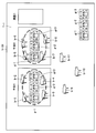
- FIG. 12 is a diagram for explaining an example of selection of the icon G-2 according to the state “estrus confirmation”.
- the view V-7 of Farmer K is shown.
- the selection unit 112 can select the icon G-2 corresponding to the state “estrus confirmation” similarly to the selection of the icon G-1 corresponding to the state “abnormality confirmation”.
- the pointer P is placed on the icon G-2 corresponding to the state “estrus confirmation”.
- FIG. 13 is a diagram illustrating an example of the field of view of the farmer K after the selection of the icon G-2 corresponding to the state “estrus confirmation”.
- the field of view V-8 of Farmer K is shown.
- the display control unit 111 guides the farmer K to visually confirm the confirmation location corresponding to the state “estrus confirmation” in the cow B-2.
- the display control unit 111 controls the auxiliary guidance display that urges the farmer K to move to a position where the confirmation location is visible because it is difficult to recognize the confirmation location when there is no confirmation location in the field of view.
- the display control unit 111 may control display of a still image or a moving image associated with the state “estrus confirmation” when the confirmation location does not exist in the visual field.
- the display control unit 111 is stationary as a guidance display for guiding the farmer K to visually confirm the confirmation place “vulva”.
- the display (AR display) of the image or video may be controlled.
- the type of still image or moving image is not limited.
- a schematic diagram K-1 is used as an example of a still image or a moving image.
- the confirmation location corresponding to the state “estrus confirmation” in cow B-1 is the vulva
- the following cases are assumed. Assume that in the server 20, the information acquisition unit 211 estimates that there is a suspicion of estrus as the state of the cow B-1.
- estrus mucus transparent watery mucus
- cow B-1 is likely to be in estrus. Therefore, when the server 20 estimates that the cow B-1 is suspected of being in estrus, it is desirable that the farmer K first confirms the state of the vulva of the cow B-1.
- the display control unit 111 in the communication terminal 10-1 is a schematic diagram for guiding the user to visually recognize the vulva of the cow.
- the AR display of K-1 may be controlled.
- a schematic diagram K-1 shows a picture of a cow's body and an arrow pointing to a part of the cow's body where the vulva exists.
- the schematic diagram K-1 is not limited to this.
- the schematic diagram K-1 is displayed as AR so as to extend from the icon G-2.
- the schematic diagram K-1 is displayed based on the position of the cow B-1, Good.
- FIG. 14 is a view showing an example of the field of view of the farmer K in which the vulva of the cow B-1 corresponding to the state “estrus confirmation” is entered.
- display control unit 111 is obtained by an image sensor included in detection unit 120 in communication terminal 10-1. The vulva is recognized from the image, and the vulva is highlighted as a confirmation location.
- the display control unit 111 similarly to the highlighted display for the confirmation place “nose”, the display is highlighted by the arrow J-1 that points to the confirmation place “the vulva” and the broken line J-2 that surrounds the confirmation place “the vulva”. Has been made.
- the display control unit 111 generates information f-1 regarding childbirth based on the individual information of the cow B-1 corresponding to the state “estrus confirmation” received by the communication unit 130 from the server 20, and information f regarding childbirth f The display of -1 may be controlled.
- the information f-1 related to childbirth includes the number of days of birth, the order of birth, the history of difficult birth, and the history of miscarriage.
- the display control unit 111 notifies the veterinarian the contact button L-1, the list addition button L-2, and the abnormality Controls the display of the none button L-3.
- the processing control unit 114 causes the communication unit 130 to transmit flag information indicating that artificial insemination is required to the server 20. May be controlled. Then, even if urgent artificial insemination is unnecessary for the cow B-1, it becomes possible to have the veterinarian M perform artificial insemination later.
- the flag information indicating the artificial insemination may be stored in association with the identification information of the cow B-1 by the storage unit 220. Then, in the communication terminal 10-2 used by the veterinarian M, a mark indicating that flag information indicating artificial insemination is attached can be displayed in an AR based on the position of the cow B-1.
- the veterinarian M can efficiently perform artificial insemination based on the artificial insemination list (identification information of the cow to which flag information indicating artificial insemination is required) and the AR display.
- the schematic diagram K-1 is used as a guidance display for guiding the farmer K to visually confirm the confirmation location “vulva”.
- a moving image may be used as a guidance display for guiding the farmer K to visually confirm the confirmation location “vulva”.
- the display control unit 111 may display-control the moving image instead of the schematic diagram K-1.
- Farmer K can check the estrus of cow B-1 by checking the video.
- FIG. 15 is a diagram for explaining an example of selecting the icon G-3 according to the state “periodic measurement”.
- a view V-10 of the farmer K is shown.
- the selection unit 112 can select the icon G-3 corresponding to the state “periodic measurement” in the same manner as the selection of the icon G-1 corresponding to the state “abnormality confirmation”.
- the pointer P is placed on the icon G-3 corresponding to the state “periodic measurement”.
- FIG. 16 is a diagram illustrating an example of the field of view of the farmer K after selection of the icon G-3 according to the state “periodic measurement”. Referring to FIG. 16, the field of view V-11 of Farmer K is shown.
- the display control unit 111 guides the farmer K to visually confirm the confirmation location corresponding to the state “periodic measurement” in the cow B-7. To control.
- the display control unit 111 may control the display (AR display) of a still image or a moving image associated with the state “periodic measurement”.
- the distance between the cow B-7 and the farmer K may be calculated by the server 20 or may be calculated by the communication terminal 10-1.
- a schematic diagram K-2 is used as an example of a still image or a moving image.
- the schematic diagram K-2 prompts the cow to approach the cow and the arrow indicating the location where the BCS can be measured in the cow's body and the cow's body.
- Guidance for example, text data
- the schematic diagram K-2 is not limited to this.
- the schematic diagram K-2 is displayed as AR extending from the icon G-3, but if the schematic diagram K-2 is displayed based on the position of the cow B-7, Good.
- FIG. 17 is a diagram illustrating an example of the field of view of the farmer K that includes a part where the BCS of the cow B-7 corresponding to the state “periodic measurement” can be measured.
- the display control unit 111 in the communication terminal 10-1 includes the image sensor included in the detection unit 120.
- the location where the BCS can be measured is recognized from the image obtained by the above, and the location where the BCS can be measured is highlighted as a confirmation location.
- the confirmation point “location where BCS can be measured” is highlighted by line J-3.
- the display control unit 111 can measure the BCS from the image. At this time, as shown in FIG. 17, the display control unit 111 can control the display of the guidance D-1 indicating that the BCS is being measured.
- guidance D-1 indicating that BCS is being measured is text data, but guidance D-1 indicating that BCS is being measured is not limited to text data.
- FIG. 18 is a diagram showing a display example of the first BCS measurement result.
- a view V-13 of farmer K is shown.
- the display control unit 111 displays the first BCS measurement result as the BCS measurement result D-2 as shown in FIG. You may let me.
- the display control unit 111 may control the display of the guidance D-3 that prompts movement.
- the guidance D-3 that prompts movement is text data, but the guidance D-3 that prompts movement is not limited to text data.
- the leftward movement is urged by the guidance D-3 for urging the movement, but the movement in any direction is urged by the guidance D-3 for urging the movement. Good.
- the farmer K may end the BCS measurement without moving.
- FIG. 19 is a diagram illustrating an example of the field of view of the farmer K in which another portion capable of measuring the BCS of the cow B-7 corresponding to the state “periodic measurement” is entered.
- the display control unit 111 is included in the detection unit 120 in the communication terminal 10-1.
- Other locations where the BCS can be measured are recognized from the image obtained by the image sensor, and the other locations where the BCS can be measured are highlighted as a confirmation location.
- the confirmation location “other location where BCS can be measured” is highlighted by line J-4.
- the display control unit 111 can measure the second BCS based on the image and the first measured BCS. At this time, as shown in FIG. 19, the display control unit 111 can control the display of the guidance D-1 indicating that the BCS is being measured. It is assumed that the second BCS measured at this time is more accurate than the BCS measured first.
- FIG. 20 is a diagram showing a display example of the second BCS measurement result.
- the view V-15 of Farmer K is shown.
- the display control unit 111 converts the second BCS measurement result into the BCS measurement result D-2 as shown in FIG. May be displayed. Further, as shown in FIG. 20, the display control unit 111 may control the display of the guidance D-4 indicating the completion of measurement.
- the guidance D-4 indicating completion of measurement is text data, but the guidance D-4 indicating completion of measurement is not limited to text data.
- the identification information, the BCS measurement result, and the measurement date of the cow B-7 are transmitted to the server 20 by the communication unit 130.
- the server 20 when the communication unit 230 receives the identification information, the BCS measurement result, and the measurement date of the cow B-7, the storage unit 250 stores the BCS measurement result and the measurement date of the cow B-7. It is linked to the identification information and stored in the cow information (database).
- FIG. 21 is a diagram showing an example of the designation operation for displaying the basic information of cow B-1.
- the view V-16 of Farmer K is shown.
- the farmer K may perform a predetermined designation operation on the cow B-1.
- the designation operation is not limited.
- an operation of applying an instruction direction (for example, a line of sight) to the body of the cow B-1, and a selection operation (for example, an utterance content of the farmer K “this cow's “Show basic information” etc.) is shown, but the designation operation for cow B-1 is not particularly limited.
- the display control part 111 is good to display the pointer P in the position where the instruction
- FIG. 22 is a diagram showing another example of the designation operation for displaying the basic information of cow B-1.
- the view V-17 of the farmer K is shown.
- an operation of applying a pointing direction (for example, line of sight) to the wearable device 40-1 worn by the cow B-1, and a selection operation for example, The farmer K's utterance content “Show me this cow's basic information”.
- FIG. 23 is a diagram showing a display example of basic information of cow B-1.
- the designation operation for designating the cow B-1 was performed by the farmer K, and the designation operation for designating the cow B-1 was detected by the detection unit 120.
- the display control unit 111 extracts the basic information F-1 of the cow B-1 from the individual information acquired from the server 20 as an example of information about the cow B-1, and the basic information F- The display of 1 may be controlled.
- the basic information F-1 is displayed as AR extending from the head of the cow B-1, but the basic information F-1 is displayed based on the position of the cow B-1. That's fine.
- the display control unit 111 displays information (for example, basic information) that does not depend on the state of the cow B-1 when the designation operation for the cow B-1 on which the icon is displayed is detected. Can be controlled.
- the display control unit 111 depends on the information on the cow B-3 (information not dependent on the state and the state of the cow B-3). It is possible to control the display of at least one of the information.
- the farmer K confirms the information that does not depend on the state of the cow B-1 that is displayed with the icon and the information of the cow B-3 that does not have the icon displayed as necessary by the designated operation. Is possible.
- FIG. 24 is a diagram illustrating an example of display by the communication terminal 10-2 used by the veterinarian M.
- the veterinarian M wearing the communication terminal 10-2 exists in the real world. More specifically, it is assumed that the veterinarian M is called from the farmer K by a video call or visits the farmer K regularly. Referring to FIG. 24, the field of view V-21 of veterinarian M is shown.
- the icon G- according to the state “abnormality check” in the cow B-2 is similar to the example described in the function of the communication terminal 10-1 used by the farmer K. 1.
- the display of the icon G-2 corresponding to the state “estrus confirmation” in the cow B-1 may be controlled.
- the display control unit 111 includes the identification information of the cow B-2 corresponding to the state “abnormality confirmation” in the abnormality confirmation list received from the communication unit 130 from the server 20. Judge that. Therefore, the display control unit 111 controls the AR display of the mark Ch indicating that the flag information indicating the diagnosis is necessary based on the position of the cow B-2.
- the mark Ch is AR-displayed so as to be attached to the icon G-1, but the mark Ch need only be displayed based on the position of the cow B-2.
- the shape of the mark Ch is not particularly limited.
- the display control unit 111 includes the identification information of the cow B-1 corresponding to the state “estrus confirmation” in the artificial insemination list received from the server 20 by the communication unit 130. Judge that. Therefore, the display control unit 111 controls the AR display of the mark Ch indicating that the flag information indicating the artificial insemination is attached based on the position of the cow B-1.
- the mark Ch is AR displayed so as to be attached to the icon G-2.
- the mark Ch may be displayed based on the position of the cow B-1.
- the shape of the mark Ch is not particularly limited.
- the display control unit 111 displays the icon G-4 corresponding to the state “pregnant”. Control the display. At this time, as shown in FIG. 24, the display control unit 111 may perform control so that the icon G-4 corresponding to the state “pregnant” is AR-displayed on the head of the cow B-7.
- the icon G displayed in this way may be selectable.
- the selection of the icon G may be performed by the selection unit 112 when a selection operation by the veterinarian M is detected by the detection unit 120 in the communication terminal 10-2.
- the variation of the selection operation is as described above.
- the icon G-1 corresponding to the state “abnormality confirmation” is selected by the communication terminal 10-2 in the same manner as the selection of the icon G-1 corresponding to the state “abnormality confirmation” by the communication terminal 10-1. Assume a case.
- FIG. 25 is a diagram illustrating an example of the field of view of the veterinarian M after the selection of the icon G-1 corresponding to the state “abnormality confirmation”.
- the veterinarian M approaches the cow B-2 corresponding to the state “abnormal confirmation”, the cow B-2 is seen to be close-up.
- the display control unit 111 indicates to the veterinarian M a confirmation location corresponding to the state “abnormality confirmation” in the cow B-2.
- the guidance display for guiding to make it visually recognize is controlled.
- the display control unit 111 guides the veterinarian M to visually confirm the confirmation location “nose”.
- the highlighted display for example, AR display
- the highlighting is performed by the arrow J-1 indicating the confirmation place “nose” and the broken line J-2 surrounding the confirmation place “nose”.
- the additional information D-5 input by the farmer K's voice input or the like is stored in the storage unit 220 in association with the identification information of the cow B-2.
- the display control unit 111 displays the additional information D-5. To control.
- the additional information D-5 is AR-displayed so as to extend from the icon G-1, but the additional information D-5 may be displayed based on the position of the cow B-1.
- the processing control unit 114 When the check point highlighted by the highlight display is examined by the veterinarian M, a treatment corresponding to the symptom is performed, and when the detection unit 120 detects that the check of the check point by the veterinarian M is completed, the processing control unit 114 The execution of the process may be controlled.
- the process controlled by the process control unit 114 is not particularly limited.
- the process controlled by the process control unit 114 may include at least one of diagnosis result input and start of a video call with another apparatus.
- the detection that the examination of the confirmation part is completed may be the detection of the selection operation by the veterinarian M.
- the display control unit 111 controls the display of the diagnosis result input button L-4 and the contact button L-5 to the farmer.
- the veterinarian M examines the confirmation portion indicated by the highlighting, the veterinarian M performs a selection operation on either the diagnosis result input button L-4 and the farmer contact button L-5.
- the process control unit 114 may select a process based on the selection operation by the veterinarian M and control the execution of the selected process.
- the processing control unit 114 detects the diagnosis result input by the veterinarian M by the detection unit 120.
- the communication unit 130 controls the transmission to the server 20.
- the diagnosis result may be input by voice.
- the diagnosis result is associated with the identification information of the cow B-2 by the storage unit 220 and stored in the electronic medical record of the cow information (data in the database). .
- diagnosis result may be used as correct answer data of machine learning processing for performing state estimation based on sensor data.
- the machine learning process may be executed by the processing unit (machine learning control unit) 212 in the server 20.
- diagnosis result by the veterinarian M may be used as correct answer data of the machine learning process by the processing unit (machine learning control unit) 212 in the server 20.
- diagnosis results obtained in the past in the communication terminal 10-2 may also be used as correct answer data of the machine learning process.
- the processing control unit 114 may start a video call with the communication terminal 10-1 used by the farmer K. A conversation between the veterinarian M and the farmer K is started through a video call. According to such a function, it becomes possible for the veterinarian M to have a hands-free conversation with the farmer K present in a remote place.
- the highlighting may interfere with the examination by the veterinarian M. Therefore, it is desirable that the highlighting can be deleted by a predetermined deletion operation by the veterinarian M. That is, in the communication terminal 10-2, when a predetermined deletion operation by the veterinarian M is detected by the detection unit 120, the display control unit 111 may delete the highlighted display.
- the predetermined deletion operation is not limited and may be a predetermined voice input.
- the icon G-2 corresponding to the state “estrus confirmation” is selected by the communication terminal 10-2 in the same manner as the icon G-2 corresponding to the state “estrus confirmation” by the communication terminal 10-1.
- the veterinarian M moves the vulva of the cow B-1 to a position where it can be visually recognized in order to perform the estrus diagnosis of the cow B-1 corresponding to the state “estrus confirmation”.
- FIG. 26 is a diagram illustrating an example of the field of view of the veterinarian M in which the vulva of the cow B-1 corresponding to the state “estrus confirmation” is entered.
- the display control unit 111 corresponds to the state “estrus confirmation” received from the server 20 by the communication unit 130.
- Information f-1 regarding childbirth may be generated based on the individual information of cow B-1, and the display of the information f-1 regarding childbirth may be controlled.
- the process control unit 114 controls the execution of the process. You can do it.
- the process controlled by the process control unit 114 is not particularly limited.
- the process whose execution is controlled by the process control unit 114 may include at least one of an estrus diagnosis result input and a video call start with another apparatus.
- the detection that the examination has ended may be detection of a selection operation by the veterinarian M.
- the display control unit 111 controls the display of the estrus diagnosis button L-6 and the contact button L-7 to the farmer.
- the selection operation is performed on either the estrus diagnosis button L-6 or the farmer contact button L-7.
- the process control unit 114 may select a process based on the selection operation by the veterinarian M and control the execution of the selected process.
- the processing control unit 114 detects the estrus diagnosis result when the detection unit 120 detects the estrus diagnosis result input by the veterinarian M. Is transmitted to the server 20 by the communication unit 130.
- the estrus diagnosis result may be input by voice.
- the estrus diagnosis result may be any of “strong”, “medium”, “weak”, and “none”.
- the estrus diagnosis result is associated with the identification information of the cow B-2 by the storage unit 220 and stored in the electronic medical record of the cow information (data in the database). Is done.
- the estrus diagnosis result may be used as correct answer data of machine learning processing for estimating a state based on sensor data.
- the machine learning process may be executed by the processing unit (machine learning control unit) 212 in the server 20.
- the estrus diagnosis result by the veterinarian M may be used as correct answer data of the machine learning process by the processing unit (machine learning control unit) 212 in the server 20.
- the estrus diagnosis result obtained in the communication terminal 10-2 in the past may also be used as correct answer data of the machine learning process.
- the veterinarian M examines the cow B-1 corresponding to the state “estrus confirmation” and confirms that the cow B-1 is in estrus, the veterinarian M performs artificial insemination on the cow B-1. Good. Further, when it is confirmed that the cow B-1 has already been artificially inseminated, the veterinarian M may perform a pregnancy test and sex determination.
- the processing control unit 114 performs control so that when the result of the pregnancy test and the sex determination input by the veterinarian M is detected by the detection unit 120, the result of the pregnancy test and the sex determination is transmitted to the server 20 by the communication unit 130. To do.
- the results of pregnancy test and sex determination may be input by voice.
- the server 20 when the result of the pregnancy test and sex determination is received by the communication unit 230, the result of the pregnancy test and sex determination is associated with the identification information of the cow B-1 by the storage unit 220 and the cow information (in the database). Data) is stored in the electronic medical record.
- the processing control unit 114 detects the selection operation by the veterinarian M for the contact button L-5 for the farmer by the detection unit 120. The execution of the same processing as in the case is controlled. That is, when the selection operation by the veterinarian M on the contact button L-7 is detected by the detection unit 120, the processing control unit 114 starts the video call with the communication terminal 10-1 used by the farmer K. Good.
- the display control unit 111 controls the AR display of the icon according to the state of the cow in the communication terminal 10-1.
- the display control unit 111 may perform control so that the state of the cow is displayed in another manner.
- the display control unit 111 controls the display of a map in which a predetermined mark is attached to a position where a cow is present on the map and a predetermined mark is attached to a position where the cow is present. Also good.
- the map display in the communication terminal 10-1 will be mainly described here, the map display may be controlled in the communication terminal 10-2 as in the communication terminal 10-1.
- FIG. 27 is a diagram showing an example of map display.
- a view V-31 of the farmer K is shown.
- the display control unit 111 displays the number of cows corresponding to the state “abnormality confirmation” based on the position information of each cow B-1 to B-11.
- the icon g is calculated for each (eg, barn A, barn B, outside the barn) and the number of cows corresponding to the state “abnormality confirmation” is attached to a predetermined position (lower right in the example shown in FIG. 27) It may be controlled to display a map T-1 with -1 added to each area.
- the display control unit 111 calculates the number of cows corresponding to the state “estrus confirmation” for each region, and displays the icon g-2 in which the number of cows corresponding to the state “estrus confirmation” is attached to a predetermined position. You may attach for every area
- the display control unit 111 calculates the number of cows corresponding to the state “periodic measurement” for each region, and an icon g-3 in which the number of cows corresponding to the state “periodic measurement” is attached to a predetermined position is displayed on the map. You may attach
- the display control unit 111 marks the positions where the cows B-1 to B-11 exist on the map T-1 based on the positional information of the cows B-1 to B-11.
- b-1 to b-11 may be attached.
- the marks b-1 to b-11 are cow images, but the types (eg, shape, color, etc.) of the marks b-1 to b-11 are not particularly limited.
- the timing at which the map T-1 is displayed is not particularly limited.
- the display control unit 111 displays the cow B-1 in the field of view V-31 based on the position information of each cow B-1 to BN and the direction of the communication terminal 10-1 (the direction of the face of the farmer K). It may be determined whether any of ⁇ BN is present. If the display control unit 111 determines that none of the cows B-1 to BN exists in the field of view V-31, the display control unit 111 may control the display of the map T-1.
- the display control unit 111 controls the display of the map T-1 when it is determined that the farm K has performed a predetermined operation based on the movement of the farm K detected by the motion sensor included in the detection unit 120. May be.
- the predetermined operation may be an operation such that the farmer K looks up (that is, an operation that tilts the top of the farmer K rearward) or an operation that looks down on the farmer K (that is, the front of the farmer K is moved forward). Tilting to the right).
- the display control unit 111 may determine whether or not the farmer K exists in a predetermined area based on the position information of the farmer K. Then, the display control unit 111 may control the display of the map T-1 when it is determined that the farmhouse K exists in the predetermined area.
- the predetermined area is not particularly limited.
- the predetermined area may be an area where it is difficult for any of the cows B-1 to BN to enter the field of view V-31 of the farmer K, or may be an office or the like.
- FIG. 27 shows an example in which the map T-1 is displayed in the entire field of view K-31 of the farmer K.
- the map T-1 may be displayed in a part of the field of view V-31 of the farmer K.
- anything may be displayed in the field of view other than the area where the map T-1 is displayed in the field of view V-31 of the farmer K.
- the display control unit 111 may perform control so that the icon G is AR-displayed in a field of view other than the area where the map T-1 is displayed.
- FIG. 28 is a diagram showing an example in which map display and AR display are performed simultaneously.
- a view V-32 of Farmer K is shown.
- the display control unit 111 calculates the number of cows corresponding to each state for each region, and the number of cows corresponding to each state is added to a predetermined position.
- the map T-2 with the icons g-1 to g-3 attached to each area may be displayed.
- the display control unit 111 may control the AR display of the icon G-1 corresponding to the state “abnormal state” in the cow B-2.
- FIG. 29 is a flowchart illustrating an operation example of the server 20 according to the embodiment of the present disclosure. Note that the flowchart shown in FIG. 29 is merely an example of the operation of the server 20. Therefore, the operation of the server 20 is not limited to the operation example of the flowchart shown in FIG.
- the communication unit 230 receives signals transmitted from various sensors (S11). Examples of the various sensors include an external sensor 30 and wearable devices 40-1 to 40-N. If the predetermined time has not elapsed (“No” in S12), control unit 210 returns to S11. On the other hand, when the predetermined time has elapsed (“Yes” in S12), the control unit 210 acquires signals received from various sensors until the predetermined time elapses, and the processing unit 212 The signals acquired by the information acquisition unit 211 are totaled (S13).
- the processing unit 212 estimates the state of each cow by counting (S14). The processing unit 212 determines whether there is a cow to be notified of the alert signal based on the state of each cow.
- the cow to be notified of the alert signal is not limited, but may be a cow corresponding to the state “I am injured” as an example.
- the processing unit 212 ends the operation.
- the communication unit 230 transmits the alert signal to the communication terminal 10-1 (S16).
- the processing unit 212 may include the identification information of the cow to be notified of the alert signal and the state of the cow in the alert signal.
- the display control unit 111 acquires the cow identification information and the cow state from the alert signal, and the cow identification information and the cow state are obtained.
- the status display may be controlled.
- FIG. 30 is a flowchart illustrating an example of the overall operation of the communication terminal 10-1 according to the embodiment of the present disclosure. Note that the flowchart shown in FIG. 30 merely shows an example of the overall operation of communication terminal 10-1. Therefore, the overall operation of communication terminal 10-1 is not limited to the operation example of the flowchart shown in FIG. 30 (for example, all or a part of S31, S34, S35, and S37) may be executed by the server 20 instead of the communication terminal 10-1. S40 to S60 will be described later.
- the display control unit 111 determines the state of the communication terminal 10-1 (S31).
- the state of the communication terminal 10-1 includes the position information of the communication terminal 10-1, the direction of the communication terminal 10-1, and the like.
- the communication unit 130 transmits the state of the communication terminal 10-1 to the server 20, based on the state of the communication terminal 10-1, the individual information of one or more cows present in the farmer's field of view is stored in the server 20. Determined by.
- the determined individual information is acquired from the server 20 via the communication unit 130 by the display control unit 111 (S32).
- the display control unit 111 controls icon display based on the individual information of the cow (S33). More specifically, the display control unit 111 determines whether there is a cow corresponding to the predetermined state with reference to the individual information of the cow, and when there is a cow corresponding to the predetermined state.
- the AR display of the icon according to a predetermined state is controlled.
- abnormality confirmation, estrus confirmation, and periodic measurement are assumed as the predetermined state.
- the control unit 110 acquires the operation of the farmer K (S34).
- the control unit 110 determines whether the operation of the farmer K is an icon selection operation (that is, a selection operation for an icon) or an individual designation operation (that is, a designation operation for a cow) (S35).
- the display control unit 111 controls the display of individual information (S36), and ends the operation.
- the display control unit 111 proceeds to S37.
- abnormality confirmation when the type of the selected icon is an abnormality confirmation (“abnormality confirmation” in S37), the control unit 110 controls the execution of the abnormality confirmation processing (S40) and ends the operation.
- estrus confirmation when the type of the selected icon is estrus confirmation (“estrus confirmation” in S37), control unit 110 controls execution of estrus confirmation processing (S50), and ends the operation.
- S40 abnormality confirmation
- regular measurement periodic measurement
- regular measurement control unit 110 controls execution of the regular measurement process (S60), and ends the operation. Details of S40 to S60 will be described below.
- FIG. 31 is a flowchart showing an example of the operation of the abnormality confirmation process S40 by the communication terminal 10-1 according to the embodiment of the present disclosure.
- the flowchart shown in FIG. 31 merely shows an example of the operation of the abnormality confirmation processing S40 by the communication terminal 10-1. Therefore, the operation of the abnormality confirmation process S40 by the communication terminal 10-1 is not limited to the operation example of the flowchart shown in FIG.
- a part of the operations shown in FIG. 31 may be executed by server 20 instead of communication terminal 10-1.
- the display control unit 111 controls the display for guiding the line of sight of the farmer K to the confirmation location corresponding to the abnormal state of the cow whose icon is selected (S41).
- the display control unit 111 may control different displays depending on whether or not a confirmation location exists in the field of view of the farmer K. For example, when a confirmation location exists in the field of view of the farmer K, the display control unit 111 may control highlighting (for example, AR display) on the confirmation location.
- the display control unit 111 may control the display of the still image or the moving image associated with the abnormal state when the confirmation location does not exist in the field of view of the farmer K.
- the process control unit 114 determines an input by the farmer K (S42).
- the processing control unit 114 starts a video call to the veterinarian M (S43), and the breeding machine 70
- the setting is changed (S45), and the operation is terminated.
- the setting change of the breeding machine 70 is not particularly limited.
- the process control unit 114 may control an automatic feeder (feeder) so as to mix medicine with the food given to the cow (to cure the cow's disease).
- the process control unit 114 may control the automatic milking machine so that cow milk does not enter the tank (to prevent mastitis cow milk from mixing with healthy cow milk).
- the process control unit 114 gives an instruction to add to the abnormality confirmation list (S44). More specifically, the process control unit 114 may control the communication unit 130 so that flag information indicating a diagnosis required is transmitted to the server 20. In the server 20, when flag information indicating a diagnosis required is received by the communication unit 230, the storage unit 220 may store the flag information in association with the identification information of the abnormal cow. Then, the process control unit 114 changes the setting of the breeding machine 70 (S45) and ends the operation.
- the processing control unit 114 transmits an no abnormality flag (that is, flag information indicating no abnormality) to the server 20.
- the communication unit 130 may be controlled as described above.
- the storage unit 220 may store the flag information in association with the identification information of the abnormal cow. Then, the process control unit 114 ends the operation.
- FIG. 32 is a flowchart showing an example of the operation of the estrus confirmation process S50 by the communication terminal 10-1 according to the embodiment of the present disclosure. Note that the flowchart shown in FIG. 32 merely shows an example of the operation of the estrus confirmation process S50 by the communication terminal 10-1. Therefore, the operation of the estrus confirmation process S50 by the communication terminal 10-1 is not limited to the operation example of the flowchart shown in FIG. 32 may be executed by the server 20 instead of the communication terminal 10-1 (for example, all or part of S52 to S56).
- the display control unit 111 controls the display for guiding the line of sight of the farmer K to the confirmation location corresponding to the estrus state of the cow whose icon is selected (S51).
- the display control unit 111 may control different displays depending on whether or not a confirmation location exists in the field of view of the farmer K. For example, when a confirmation location exists in the field of view of the farmer K, the display control unit 111 may control highlighting (for example, AR display) on the confirmation location.
- the display control part 111 may control the display of the still image or moving image matched with the estrus state, when the confirmation location does not exist in the visual field of the farmer K.
- the process control unit 114 determines an input by the farmer K (S52).
- the processing control unit 114 starts a video call to the veterinarian M (S53), and the breeding machine 70
- the setting is changed (S55), and the operation is terminated.
- the setting change of the breeding machine 70 is not particularly limited.
- the process control unit 114 may control the gate so that a cow in an estrus state is guided to a different section from other cows.
- the process control part 114 may control an automatic feeder (feeder) so that the amount of feeding by an automatic feeder (feeder) may become the amount of feeding according to the estrus state.
- the process control unit 114 gives an instruction to add to the artificial insemination list (S54). More specifically, the process control unit 114 may control the communication unit 130 so that flag information indicating artificial insemination is transmitted to the server 20. In the server 20, when the flag information indicating the artificial insemination is received by the communication unit 230, the storage unit 220 may store the flag information in association with the identification information of the cow in the estrus state. Then, the process control unit 114 changes the setting of the breeding machine 70 (S55) and ends the operation.
- the processing control unit 114 transmits an abnormality-free flag (that is, flag information indicating no abnormality) to the server 20.
- the communication unit 130 may be controlled as described above.
- the storage unit 220 may store the flag information in association with the identification information of the estrus cow. Then, the process control unit 114 ends the operation.
- FIG. 33 is a flowchart illustrating an example of the operation of the regular measurement process S60 by the communication terminal 10-1 according to the embodiment of the present disclosure. Note that the flowchart shown in FIG. 33 merely shows an example of the operation of the regular measurement process S60 by the communication terminal 10-1. Therefore, the operation of the periodic measurement process S60 by the communication terminal 10-1 is not limited to the operation example of the flowchart shown in FIG. 33 (for example, all or part of S62 to S65) may be executed by server 20 instead of communication terminal 10-1.
- the display control unit 111 controls the display for guiding the line of sight of the farmer K to the confirmation location corresponding to the periodic measurement of the cow whose icon is selected (S61).
- the display control unit 111 may control different displays depending on whether or not a confirmation location exists in the field of view of the farmer K. For example, when a confirmation location exists in the field of view of the farmer K, the display control unit 111 may control highlighting (for example, AR display) on the confirmation location.
- the display control unit 111 may control the display of the still image or the moving image associated with the regular measurement when the confirmation location does not exist in the field of view of the farmer K.
- the detection unit 120 tries to detect data necessary for measurement (S62), and the display control unit 111 detects that data necessary for measurement is not detected by the detection unit 120 ("No" in S63).
- the display for guiding the farmer's line of sight to the next confirmation point is controlled (S66), and the process proceeds to S62.
- the detection unit 120 detects data necessary for measurement (“Yes” in S63)
- the display control unit 111 controls display of the measurement result
- the process control unit 114 controls recording of the measurement result. (S64).
- the measurement result is transmitted to the server 20 by the communication unit 130 and is stored in the storage unit 220 in the server 20.
- the process control unit 114 changes the setting of the breeding machine 70 (S65) and ends the operation.
- the setting change of the breeding machine 70 is not particularly limited.
- the process control unit 114 may control the automatic feeder (feeder) so as to change the amount of feeding according to the measurement result. More specifically, the process control unit 114 may control the automatic feeder (feeder) so as to reduce the amount of feeding when the BCS exceeds the first threshold value. On the other hand, the process control unit 114 may control the automatic feeder (feeder) so as to increase the amount of feeding when the BCS falls below the second threshold.
- the process control unit 114 may control the automatic milking machine so as to change the milking amount according to the measurement result. More specifically, when the BCS exceeds the third threshold, the automatic milking machine may be controlled to increase the milking amount. On the other hand, the process control unit 114 may control the automatic milking machine so that the milking amount becomes zero when the BCS falls below the fourth threshold value.
- FIG. 34 is a flowchart illustrating an operation example of the display control system 1 according to the embodiment of the present disclosure. Note that the flowchart shown in FIG. 34 merely shows an example of the operation of the display control system 1. Therefore, the operation of the display control system 1 is not limited to the operation example of the flowchart shown in FIG.
- an input process is executed by the detection unit 120 (S71).
- detection of the state (position information and orientation) of the communication terminal 10-1 can be mentioned.
- the communication unit 130 transmits a request corresponding to the input process to the server 20 (S72).
- the request may include the state of the communication terminal 10-1.
- the control unit 210 executes processing for the request (S73).
- the information acquisition unit 211 may acquire individual information of the cows present in the farmer's field of view based on the state of the communication terminal 10-1 and the position information of each cow.
- the server 20 when a response based on the processing result is transmitted by the communication unit 230 (S74), the response is received by the communication unit 130 in the communication terminal 10-1.
- the response may include individual information on cattle present in the farmer's field of view.
- display processing based on the response is executed by the output unit 160 (S75).
- the display process may be a process of displaying an icon based on individual information of cows present in the farmer's field of view.
- FIG. 35 is a block diagram illustrating a hardware configuration example of the communication terminal 10 according to the embodiment of the present disclosure.
- the hardware configuration of the server 20 according to the embodiment of the present disclosure can also be realized in the same manner as the hardware configuration example of the communication terminal 10 illustrated in FIG.
- the communication terminal 10 includes a CPU (Central Processing unit) 901, a ROM (Read Only Memory) 903, and a RAM (Random Access Memory) 905.
- the control unit 110 can be realized by the CPU 901, the ROM 903, and the RAM 905.
- the communication terminal 10 may include a host bus 907, a bridge 909, an external bus 911, an interface 913, an input device 915, an output device 917, a storage device 919, a drive 921, a connection port 923, and a communication device 925.
- the communication terminal 10 may include an imaging device 933 and a sensor 935 as necessary.
- the communication terminal 10 may have a processing circuit called DSP (Digital Signal Processor) or ASIC (Application Specific Integrated Circuit) instead of or in addition to the CPU 901.
- DSP Digital Signal Processor
- ASIC Application Specific Integrated Circuit
- the CPU 901 functions as an arithmetic processing unit and a control unit, and controls all or a part of the operation in the communication terminal 10 according to various programs recorded in the ROM 903, the RAM 905, the storage device 919, or the removable recording medium 927.
- the ROM 903 stores programs and calculation parameters used by the CPU 901.
- the RAM 905 temporarily stores programs used in the execution of the CPU 901, parameters that change as appropriate during the execution, and the like.
- the CPU 901, the ROM 903, and the RAM 905 are connected to each other by a host bus 907 configured by an internal bus such as a CPU bus. Further, the host bus 907 is connected to an external bus 911 such as a PCI (Peripheral Component Interconnect / Interface) bus via a bridge 909.
- PCI Peripheral Component Interconnect / Interface
- the input device 915 is a device operated by the user such as a button.
- the input device 915 may include a mouse, a keyboard, a touch panel, a switch, a lever, and the like.
- the input device 915 may include a microphone that detects a user's voice.
- the input device 915 may be, for example, a remote control device using infrared rays or other radio waves, or may be an external connection device 929 such as a mobile phone corresponding to the operation of the communication terminal 10.
- the input device 915 includes an input control circuit that generates an input signal based on information input by the user and outputs the input signal to the CPU 901. The user operates the input device 915 to input various data and instruct processing operations to the communication terminal 10.
- An imaging device 933 which will be described later, can also function as an input device by imaging a user's hand movement, a user's finger, and the like. At this time, the pointing position may be determined according to the movement of the hand or the direction of the finger. Note that the detection unit 120 described above can be realized by the input device 915.
- the output device 917 is a device that can notify the user of the acquired information visually or audibly.
- the output device 917 can be, for example, a display device such as an LCD (Liquid Crystal Display) or an organic EL (Electro-Luminescence) display, or a sound output device such as a speaker or headphones. Further, the output device 917 may include a PDP (Plasma Display Panel), a projector, a hologram, a printer device, and the like.
- the output device 917 outputs the result obtained by the processing of the communication terminal 10 as a video such as text or an image, or as a sound such as voice or sound.
- the output device 917 may include a light or the like to brighten the surroundings. Note that the output device 160 can realize the output unit 160 described above.
- the storage device 919 is a data storage device configured as an example of a storage unit of the communication terminal 10.
- the storage device 919 includes, for example, a magnetic storage device such as an HDD (Hard Disk Drive), a semiconductor storage device, an optical storage device, or a magneto-optical storage device.
- the storage device 919 stores programs executed by the CPU 901, various data, various data acquired from the outside, and the like.
- the drive 921 is a reader / writer for a removable recording medium 927 such as a magnetic disk, an optical disk, a magneto-optical disk, or a semiconductor memory, and is built in or externally attached to the communication terminal 10.
- the drive 921 reads information recorded on the attached removable recording medium 927 and outputs the information to the RAM 905.
- the drive 921 writes a record in the attached removable recording medium 927.
- the connection port 923 is a port for directly connecting a device to the communication terminal 10.
- the connection port 923 can be, for example, a USB (Universal Serial Bus) port, an IEEE 1394 port, a SCSI (Small Computer System Interface) port, or the like.
- the connection port 923 may be an RS-232C port, an optical audio terminal, an HDMI (registered trademark) (High-Definition Multimedia Interface) port, or the like.
- the communication device 925 is a communication interface configured with a communication device for connecting to the network 931, for example.
- the communication device 925 can be, for example, a communication card for wired or wireless LAN (Local Area Network), Bluetooth (registered trademark), or WUSB (Wireless USB).
- the communication device 925 may be a router for optical communication, a router for ADSL (Asymmetric Digital Subscriber Line), or a modem for various communication.
- the communication device 925 transmits and receives signals and the like using a predetermined protocol such as TCP / IP with the Internet and other communication devices, for example.
- the network 931 connected to the communication device 925 is a wired or wireless network, such as the Internet, a home LAN, infrared communication, radio wave communication, or satellite communication.
- the communication unit 925 can realize the communication unit 130 described above.
- the imaging device 933 uses various members such as an imaging element such as a CCD (Charge Coupled Device) or CMOS (Complementary Metal Oxide Semiconductor), and a lens for controlling the imaging of a subject image on the imaging element. It is an apparatus that images a real space and generates a captured image.
- the imaging device 933 may capture a still image or may capture a moving image. Note that the above-described detection unit 120 can be realized by the imaging device 933.
- the sensor 935 is various sensors such as a distance measuring sensor, an acceleration sensor, a gyro sensor, a geomagnetic sensor, a vibration sensor, an optical sensor, and a sound sensor.
- the sensor 935 acquires information related to the surrounding environment of the communication terminal 10 such as information related to the state of the communication terminal 10 itself such as the attitude of the casing of the communication terminal 10 and brightness and noise around the communication terminal 10.
- the sensor 935 may include a GPS sensor that receives a GPS (Global Positioning System) signal and measures the latitude, longitude, and altitude of the apparatus.
- GPS Global Positioning System
- an image corresponding to the state of the management target existing in the user's field of view is displayed at a position having a predetermined positional relationship with the position of the management target.
- a display control unit that controls the display, and the display control unit guides the user to visually recognize a confirmation location corresponding to the state of the management object when the image is selected.
- a display control device for controlling display is provided. If it does so, it will become possible to provide the technique which can perform management of a subject more easily.
- each component is not particularly limited.
- Part of the processing of each unit in the communication terminal 10 may be performed by the server 20.
- a part or all of each block (display control unit 111, selection unit 112, determination unit 113, processing control unit 114) included in the control unit 110 in the communication terminal 10 exists in the server 20 or the like. May be.
- part of the processing of each unit in the server 20 may be performed by the communication terminal 10.
- one or a plurality of relay devices that perform a part of the processing of each component may exist in the display control system 1.
- the relay device can be, for example, a smartphone that the user has.
- the relay device includes a communication circuit that communicates with the display control device 10 and the server 20 in a case of the relay device, and a processing circuit that performs a part of the processing performed by each block in the above embodiment. Have. Then, for example, the relay device receives predetermined data from the communication unit 230 of the server 20, performs a part of the processing of each component, and transmits the data to the communication unit 130 of the display control device 10 based on the processing result.
- the relay device by performing communication and processing in the opposite direction, effects similar to those of the above-described operation examples of the display control device 10 and the server 20 are brought about.
- a display control unit that performs control so that an image corresponding to a state of a management target existing in a user's field of view is displayed at a position having a predetermined positional relationship with the position of the management target;
- the display control unit controls a guidance display for guiding the user to visually confirm a confirmation location according to the state of the management target when the image is selected.
- Display control device (2)
- the management object is livestock,
- the transmitted confirmation result input data is recorded in association with identification information for identifying the livestock.
- the display control apparatus according to (2).
- the display control unit controls display of an icon image corresponding to a state category as the image; The display control apparatus according to any one of (1) to (3).
- the display control unit performs control so that the image is displayed for a management object that satisfies a first condition among the plurality of management objects, and a second that is different from the first condition.
- the display of the image is restricted for the management object that is in a state that satisfies the condition,
- the display control apparatus according to any one of (1) to (4).
- a housing comprising the display and configured to be attachable to the user's head;
- a non-contact sensor for detecting an image selection operation according to the state of the management object;
- the display control apparatus according to any one of (1) to (5).
- the non-contact sensor detects at least one of the user's gesture, the user's line of sight, and the user's voice command;
- the display control apparatus according to (6).
- the display control unit controls an auxiliary guidance display that prompts the user to move to a position where the confirmation location is visible when the confirmation location does not exist in the visual field.
- the display control device according to any one of (1) to (7).
- the display control unit when the confirmation location is present in the field of view, controls the highlighted display for the confirmation location as the guidance display, The display control apparatus according to any one of (1) to (8).
- the display control unit controls display of a still image or a moving image associated with the state when a distance between the management object and the user is larger than a predetermined distance.
- the display control device according to any one of (1) to (9).
- the display control unit controls display of the image according to a display mode according to the priority of the state.
- the display control apparatus according to any one of (1) to (10).
- the display control device includes: A selection unit configured to select the image when a selection operation is performed in a state where a pointer exists at the position of the image or a position close to the image; The display control apparatus according to any one of (1) to (11). (13) The display control unit enlarges the image when the pointer exists at a position of the image or a position close to the image; The display control apparatus according to (12). (14) The display control unit controls display of information indicating display or non-display of the image for each state; The display control apparatus according to any one of (1) to (13). (15) The display control unit controls display of an image according to the state when the state of the management object corresponds to the position or action of the user. The display control apparatus according to any one of (1) to (14).
- the display control unit selects a predetermined state from the states of the plurality of management objects based on the priorities of the states of the plurality of management objects.
- the display control device includes a processing control unit that controls execution of processing, The process includes a process for starting a video call with another device, a process for adding the ID of the management object to the list, and a process for adding information indicating that there is no abnormality in the state of the management object Including at least one of The display control apparatus according to any one of (1) to (16).
- a communication unit that transmits confirmation result input data by the user based on the guidance display to a server;
- the server includes a machine learning control unit that performs a machine learning process for estimating a state of the management object based on sensor data about the management object, and the confirmation result input data is the machine learning process performed by the server. Used as correct data for The display control device according to (1).
- the display control unit controls the image to be displayed with a size corresponding to a distance between the management target and the user.
- the display control apparatus according to any one of (1) to (18).
- the display control unit controls display of information on the management object when a predetermined designation operation for designating the management object is performed;
- the display control apparatus according to any one of (1) to (19).
- the display control unit is a position where the management target exists when the management target does not exist in the field of view, when the user performs a predetermined operation, or when the user exists in a predetermined area. Control the display of a map with a predetermined mark on the The display control apparatus according to any one of (1) to (20).
- the display control unit selects a predetermined state from the plurality of states based on the priority of each of the plurality of states, and according to each of the predetermined states Control the display of images, The display control apparatus according to any one of (1) to (21).
- the process control unit selects the process based on a selection result or sensor data by the user.
- the display control device according to (17).
Abstract
[Problem] The provision of a technology is desired whereby it is possible to more easily carry out management of an object. [Solution] Provided is a display control device, comprising a display control unit which controls such that an image based on a state of an object to be managed which is present within a user's field of vision is displayed in a position which has a prescribed position relation to the position of the object to be managed. If the image is selected, the display control unit controls a guidance display for guiding so as to cause the user to view a verification site based on the state with respect to the object to be managed.
Description
本開示は、表示制御装置、表示制御方法およびプログラムに関する。
The present disclosure relates to a display control device, a display control method, and a program.
近年、対象物を管理するための技術として様々な技術が知られている。例えば、対象物の例としての家畜を管理するための技術が知られている。また、家畜を管理するための技術として様々な技術が開示されている。例えば、GNSS(Global Navigation Satellite System)による位置情報を用いて、家畜を管理する技術が開示されている(例えば、特許文献1参照。)。
In recent years, various techniques are known as techniques for managing objects. For example, a technique for managing livestock as an example of an object is known. Various techniques are disclosed as techniques for managing livestock. For example, a technique for managing livestock using position information by GNSS (Global Navigation Satellite System) is disclosed (for example, see Patent Document 1).
しかし、対象物の管理をより容易に行うことが可能な技術が提供されることが望まれる。
However, it is desirable to provide a technology that makes it easier to manage objects.
本開示によれば、ユーザの視野に存在する管理対象物の状態に応じた画像が、前記管理対象物の位置と所定の位置関係を有する位置に表示されるように制御する表示制御部を備え、前記表示制御部は、前記画像が選択された場合に、前記管理対象物における前記状態に応じた確認箇所を前記ユーザに視認させるように誘導するための誘導表示を制御する、表示制御装置が提供される。
According to the present disclosure, the display control unit is configured to perform control so that an image corresponding to the state of the management target existing in the user's field of view is displayed at a position having a predetermined positional relationship with the position of the management target. The display control unit is configured to control a guidance display for guiding the user to visually confirm a confirmation location corresponding to the state of the management target when the image is selected. Provided.
本開示によれば、プロセッサにより、ユーザの視野に存在する管理対象物の状態に応じた画像が、前記管理対象物の位置と所定の位置関係を有する位置に表示されるように制御することを含み、前記画像が選択された場合に、前記管理対象物における前記状態に応じた確認箇所を前記ユーザに視認させるように誘導するための誘導表示を制御することを含む、表示制御方法が提供される。
According to the present disclosure, the processor controls to display an image corresponding to the state of the management target existing in the user's field of view at a position having a predetermined positional relationship with the position of the management target. And a display control method including controlling a guidance display for guiding the user to visually confirm a confirmation location corresponding to the state of the management target when the image is selected. The
本開示によれば、コンピュータを、ユーザの視野に存在する管理対象物の状態に応じた画像が、前記管理対象物の位置と所定の位置関係を有する位置に表示されるように制御する表示制御部を備え、前記表示制御部は、前記画像が選択された場合に、前記管理対象物における前記状態に応じた確認箇所を前記ユーザに視認させるように誘導するための誘導表示を制御する、表示制御装置として機能させるためのプログラムが提供される。
According to the present disclosure, display control for controlling the computer so that an image corresponding to the state of the management target existing in the user's field of view is displayed at a position having a predetermined positional relationship with the position of the management target. The display control unit controls a guidance display for guiding the user to visually confirm a confirmation location corresponding to the state of the management object when the image is selected. A program for functioning as a control device is provided.
以上説明したように本開示によれば、対象物の管理をより容易に行うことが可能な技術が提供される。なお、上記の効果は必ずしも限定的なものではなく、上記の効果とともに、または上記の効果に代えて、本明細書に示されたいずれかの効果、または本明細書から把握され得る他の効果が奏されてもよい。
As described above, according to the present disclosure, a technique capable of managing an object more easily is provided. Note that the above effects are not necessarily limited, and any of the effects shown in the present specification, or other effects that can be grasped from the present specification, together with or in place of the above effects. May be played.
以下に添付図面を参照しながら、本開示の好適な実施の形態について詳細に説明する。なお、本明細書及び図面において、実質的に同一の機能構成を有する構成要素については、同一の符号を付することにより重複説明を省略する。
Hereinafter, preferred embodiments of the present disclosure will be described in detail with reference to the accompanying drawings. In addition, in this specification and drawing, about the component which has the substantially same function structure, duplication description is abbreviate | omitted by attaching | subjecting the same code | symbol.
また、本明細書および図面において、実質的に同一または類似の機能構成を有する複数の構成要素を、同一の符号の後に異なる数字を付して区別する場合がある。ただし、実質的に同一または類似の機能構成を有する複数の構成要素の各々を特に区別する必要がない場合、同一符号のみを付する。また、異なる実施形態の類似する構成要素については、同一の符号の後に異なるアルファベットを付して区別する場合がある。ただし、類似する構成要素の各々を特に区別する必要がない場合、同一符号のみを付する。
In the present specification and drawings, a plurality of constituent elements having substantially the same or similar functional configuration may be distinguished by adding different numerals after the same reference numerals. However, when it is not necessary to particularly distinguish each of a plurality of constituent elements having substantially the same or similar functional configuration, only the same reference numerals are given. In addition, similar components in different embodiments may be distinguished by attaching different alphabets after the same reference numerals. However, if it is not necessary to distinguish each similar component, only the same reference numerals are given.
なお、説明は以下の順序で行うものとする。
0.概要
1.本開示の実施形態
1.1.システム構成例
1.2.通信端末の機能構成例
1.3.サーバの機能構成例
1.4.外部センサの機能構成例
1.5.装着型デバイスの機能構成例
1.6.表示制御システムの機能詳細
1.6.1.農家によって用いられる通信端末
1.6.2.獣医によって用いられる通信端末
1.6.3.地図表示
1.6.4.動作例
1.7.ハードウェア構成例
2.むすび The description will be made in the following order.
0.Overview 1. Embodiment of the present disclosure 1.1. System configuration example 1.2. Functional configuration example of communication terminal 1.3. Functional configuration example of server 1.4. Example of functional configuration of external sensor 1.5. Functional configuration example of wearable device 1.6. Detailed function of display control system 1.6.1. Communication terminals used by farmers 1.6.2. Communication terminals used by veterinarians 1.6.3. Map display 1.6.4. Example of operation 1.7. 1. Hardware configuration example Conclusion
0.概要
1.本開示の実施形態
1.1.システム構成例
1.2.通信端末の機能構成例
1.3.サーバの機能構成例
1.4.外部センサの機能構成例
1.5.装着型デバイスの機能構成例
1.6.表示制御システムの機能詳細
1.6.1.農家によって用いられる通信端末
1.6.2.獣医によって用いられる通信端末
1.6.3.地図表示
1.6.4.動作例
1.7.ハードウェア構成例
2.むすび The description will be made in the following order.
0.
<0.概要>
近年、対象物を管理するための技術として様々な技術が知られている。例えば、対象物の例としての家畜を管理するための技術が知られている。また、家畜を管理するための技術として様々な技術が開示されている。例えば、GNSS(Global Navigation Satellite System)による位置情報を用いて、家畜を管理する技術が開示されている(例えば、特開2008-73005号公報参照。)。しかし、対象物の管理をより容易に行うことが可能な技術が提供されることが望まれる。 <0. Overview>
In recent years, various techniques are known as techniques for managing an object. For example, a technique for managing livestock as an example of an object is known. Various techniques are disclosed as techniques for managing livestock. For example, a technique for managing livestock using position information by GNSS (Global Navigation Satellite System) has been disclosed (see, for example, JP-A-2008-73005). However, it is desirable to provide a technique that can more easily manage an object.
一例として、乳牛などの家畜は、飼育頭数が100頭を超える場合もあれば、1000頭を超える場合もある。そのため、乳牛などの家畜は、複数をまとめて群として管理する必要がある(群管理が必要である)。以下では、群管理される管理対象物として家畜(特に、家畜として牛)を例に挙げながら説明するが、群管理される管理対象物は、家畜に限定されない。例えば、群管理される管理対象物は、家畜以外の生物(例えば、人間など)であってもよいし、無生物(例えば、ロボットまたは車両などの移動体)であってもよい。
As an example, livestock such as dairy cows may have more than 100 animals or more than 1000 animals. Therefore, it is necessary to manage a plurality of livestock such as dairy cows as a group (group management is necessary). In the following description, a livestock (particularly, cattle as livestock) will be described as an example of a management target subject to group management. However, a management target subject to group management is not limited to livestock. For example, the management target subject to group management may be a living organism other than livestock (for example, a human) or an inanimate organism (for example, a moving body such as a robot or a vehicle).
また、本明細書においては、牛群が屋内の飼育場に存在する場合を主に想定する。しかし、牛群が存在する場所は屋内の飼育場に限定されない。例えば、牛群は屋外の飼育場に存在してもよい。また、本明細書においては、ユーザが牛に対して作業を行う農家である場合、および、ユーザが牛の状態を診る獣医である場合を主に想定する。しかし、ユーザは農家に限定されないし、ユーザは獣医に限定されない。
In addition, in this specification, it is mainly assumed that the herd is in an indoor breeding ground. However, the place where the herd is located is not limited to indoor breeding grounds. For example, the herd may be in an outdoor breeding ground. Moreover, in this specification, the case where a user is a farmer who works with respect to a cow and the case where a user is a veterinarian who examines the state of a cow are mainly assumed. However, the user is not limited to a farmer, and the user is not limited to a veterinarian.
ここで、例として、農家が牛群から状態(例えば、健康状態など)が悪い牛を特定し、特定した牛に対して作業を行おうとする場合、または、特定した牛を獣医に診てもらうために獣医を呼ぼうとする場合などを想定する。かかる場合に、牛群に含まれる全部の牛の状態が携帯端末などに表示されるようにすると、全部の牛の状態が非常に煩雑に表示されてしまうため、牛の特定自体が困難な場合があり得る。また、牛の特定ができた場合であっても、牛の状態に応じた確認を行うことが困難な場合があり得る。
Here, as an example, when a farmer identifies a cow in bad condition (for example, health condition) from a herd and tries to work on the identified cow, or asks a veterinarian to identify the identified cow Suppose you want to call a veterinarian. In such a case, if the state of all the cows included in the herd is displayed on a mobile terminal or the like, the state of all the cows will be displayed very cumbersome, so it is difficult to identify the cows themselves There can be. Moreover, even if it is a case where the cow is identified, it may be difficult to perform confirmation according to the state of the cow.
そこで、本明細書においては、牛群から牛を容易に特定することが可能な技術について説明する。また、本明細書においては、特定した牛の状態に応じた確認を容易に行うことが可能な技術について説明する。また、農家が家畜の世話をしている場合には、農家の手が汚れている場合が多い。そのため、農家が家畜の世話をしている場合に、農家がタッチパネルを用いて操作を行うのが困難な場合があり得る。そこで、本明細書においては、農家が手を使わずに容易に操作を行うことが可能な技術についても説明する。
Therefore, in this specification, a technique capable of easily identifying a cow from a herd will be described. Moreover, in this specification, the technique which can confirm easily according to the state of the specified cow is demonstrated. In addition, when a farmer takes care of livestock, the farmer's hands are often dirty. Therefore, when a farmer is taking care of livestock, it may be difficult for the farmer to perform an operation using the touch panel. Therefore, in this specification, a technique that can be easily operated by a farmer without using a hand will be described.
以上、本開示の一実施形態の概要について説明した。
The overview of the embodiment of the present disclosure has been described above.
<1.本開示の実施形態>
[1.1.システム構成例]
続いて、図面を参照しながら、本開示の一実施形態に係る表示制御システムの構成例について説明する。図1は、本開示の一実施形態に係る表示制御システムの構成例を示す図である。図1に示したように、表示制御システム1は、表示制御装置(以下、「通信端末」とも言う。)10-1と、表示制御装置(以下、「通信端末」とも言う。)10-2と、サーバ20と、外部センサ30と、装着型デバイス40-1~40-Nと、中継器50-1、50-2と、ゲートウェイ装置60と、飼育用機械70と、ネットワーク931とを備える。 <1. Embodiment of the present disclosure>
[1.1. System configuration example]
Subsequently, a configuration example of a display control system according to an embodiment of the present disclosure will be described with reference to the drawings. FIG. 1 is a diagram illustrating a configuration example of a display control system according to an embodiment of the present disclosure. As shown in FIG. 1, thedisplay control system 1 includes a display control device (hereinafter also referred to as “communication terminal”) 10-1 and a display control device (hereinafter also referred to as “communication terminal”) 10-2. A server 20, an external sensor 30, wearable devices 40-1 to 40 -N, repeaters 50-1 and 50-2, a gateway device 60, a breeding machine 70, and a network 931. .
[1.1.システム構成例]
続いて、図面を参照しながら、本開示の一実施形態に係る表示制御システムの構成例について説明する。図1は、本開示の一実施形態に係る表示制御システムの構成例を示す図である。図1に示したように、表示制御システム1は、表示制御装置(以下、「通信端末」とも言う。)10-1と、表示制御装置(以下、「通信端末」とも言う。)10-2と、サーバ20と、外部センサ30と、装着型デバイス40-1~40-Nと、中継器50-1、50-2と、ゲートウェイ装置60と、飼育用機械70と、ネットワーク931とを備える。 <1. Embodiment of the present disclosure>
[1.1. System configuration example]
Subsequently, a configuration example of a display control system according to an embodiment of the present disclosure will be described with reference to the drawings. FIG. 1 is a diagram illustrating a configuration example of a display control system according to an embodiment of the present disclosure. As shown in FIG. 1, the
本明細書においては、ネットワーク931が無線LAN(Local Area Network)である場合を主に想定するが、後にも説明するように、ネットワーク931の種類は限定されない。また、中継器50(中継器50-1、50-2)は、装着型デバイス40(装着型デバイス40-1~40-N)とサーバ20との間の通信を中継する。図1に示した例では、中継器50の数が2つであるが、中継器50の数は、2つに限定されず、複数であればよい。ゲートウェイ装置60は、ネットワーク931と中継器50(中継器50-1、50-2)および外部センサ30とを接続する。
In this specification, the case where the network 931 is a wireless LAN (Local Area Network) is mainly assumed, but the type of the network 931 is not limited as will be described later. Further, the relay device 50 (relay devices 50-1 and 50-2) relays communication between the wearable device 40 (wearable devices 40-1 to 40-N) and the server 20. In the example illustrated in FIG. 1, the number of repeaters 50 is two, but the number of repeaters 50 is not limited to two and may be plural. The gateway device 60 connects the network 931 to the repeaters 50 (relay devices 50-1 and 50-2) and the external sensor 30.
通信端末10-1は、農家Kによって用いられる装置である。農家Kは、牛B-1~B-N(Nは2以上の整数)を飼育する飼育者である。通信端末10-1は、ネットワーク931に接続されており、農家Kの視野に存在する牛の位置に応じて画像(以下、「アイコン」とも言う。)を表示し、サーバ20との間で適宜必要な情報を送受信することによって、農家Kによる牛の管理を円滑に行うことを可能にする。アイコンは、通信端末10-1によって記憶されていてもよいし、サーバ20によって記憶されていてもよい。
The communication terminal 10-1 is a device used by the farmer K. Farmer K is a breeder who raises cows B-1 to BN (N is an integer of 2 or more). The communication terminal 10-1 is connected to the network 931, displays an image (hereinafter also referred to as “icon”) according to the position of the cow present in the field of view of the farmer K, and appropriately communicates with the server 20. By transmitting and receiving necessary information, it is possible to manage cows smoothly by the farmer K. The icon may be stored by the communication terminal 10-1, or may be stored by the server 20.
なお、本明細書においては、農家Kが手作業を効率的に行うことを考慮し、通信端末10-1が農家Kに装着されるタイプ(例えば、グラスタイプ、ヘッドマウントディスプレイ)のデバイスである場合を想定する。しかし、通信端末10-1は、農家Kに装着されないタイプのデバイス(例えば、スマートフォン、壁に取り付けられるパネル型ディスプレイなど)であってもよい。また、本明細書においては、通信端末10-1がシースルー型のデバイスである場合を想定する。しかし、通信端末10-1は非シースルー型のデバイスであってもよい。
In this specification, considering that the farmer K efficiently performs manual work, the communication terminal 10-1 is a device of a type (for example, a glass type or a head-mounted display) that is attached to the farmer K. Assume a case. However, the communication terminal 10-1 may be a device of a type that is not attached to the farmer K (for example, a smartphone, a panel display attached to a wall, etc.). In this specification, it is assumed that the communication terminal 10-1 is a see-through device. However, the communication terminal 10-1 may be a non-see-through device.
通信端末10-2は、獣医Mによって用いられる装置である。獣医Mは、牛B-1~B-Nの怪我または病気を治療する。通信端末10-2は、ネットワーク931に接続されており、農家Kによって用いられる通信端末10-1との間でサーバ20を介して各種通信および情報共有が可能である。例えば、通信端末10-2は、農家Kによって用いられる通信端末10-1との間で通話が可能であり、農家Kの操作に基づいて登録された牛のチェック結果リストの閲覧を可能とする。獣医Mは、農家Kからの通話での要請によって、または、チェック結果リストの閲覧によって、その農家Kの牛のケアの必要性を確認し、農家Kの牧場へ赴いて医療行為を行う。
The communication terminal 10-2 is a device used by the veterinarian M. Veterinarian M treats an injury or illness of cattle B-1 to BN. The communication terminal 10-2 is connected to the network 931 and can perform various types of communication and information sharing with the communication terminal 10-1 used by the farmer K via the server 20. For example, the communication terminal 10-2 can make a call with the communication terminal 10-1 used by the farmer K, and can browse a check result list of cattle registered based on the operation of the farmer K. . The veterinarian M confirms the necessity of care for the cows of the farmer K by a request by a call from the farmer K or by browsing the check result list, and visits the farm of the farmer K to perform a medical practice.
なお、本明細書においては、獣医Mが手作業を効率的に行うことを考慮し、通信端末10-2が獣医Mに装着されるタイプ(例えば、グラスタイプ、ヘッドマウントディスプレイ)のデバイスである場合を想定する。しかし、通信端末10-2は、獣医Mに装着されないタイプのデバイス(例えば、スマートフォン、壁に取り付けられるパネル型ディスプレイなど)であってもよい。また、本明細書においては、通信端末10-2がシースルー型のデバイスである場合を想定する。しかし、通信端末10-2は非シースルー型のデバイスであってもよい。
In this specification, considering that the veterinarian M performs manual work efficiently, the communication terminal 10-2 is a device of a type (for example, a glass type, a head mounted display) that is attached to the veterinarian M. Assume a case. However, the communication terminal 10-2 may be a device of a type that is not attached to the veterinarian M (for example, a smartphone, a panel display attached to a wall, or the like). In the present specification, it is assumed that the communication terminal 10-2 is a see-through device. However, the communication terminal 10-2 may be a non-see-through device.
外部センサ30は、牛B(牛B-1~B-N)の身体に直接的には装着されないセンサである。本明細書においては、外部センサ30が監視カメラである場合を主に想定するが、外部センサ30は、監視カメラに限定されない。例えば、外部センサ30は、カメラ搭載型のドローンであってもよい。また、本明細書においては、外部センサ30が牛B(牛B-1~B-N)の一部または全部を俯瞰するように撮像することによって画像(以下、「俯瞰画像」とも言う。)を得る場合を主に想定する。しかし、外部センサ30の向きは限定されない。
The external sensor 30 is a sensor that is not directly attached to the body of the cow B (cow B-1 to BN). In this specification, the case where the external sensor 30 is a monitoring camera is mainly assumed, but the external sensor 30 is not limited to the monitoring camera. For example, the external sensor 30 may be a camera-mounted drone. Further, in this specification, the external sensor 30 captures an image so as to overlook a part or all of the cow B (cow B-1 to BN) (hereinafter also referred to as “overhead image”). Suppose that However, the direction of the external sensor 30 is not limited.
また、本明細書においては、外部センサ30が可視光カメラである場合を主に想定する。しかし、外部センサ30の種類は限定されない。例えば、外部センサ30は、赤外線サーモグラフィカメラであってもよい。外部センサ30が赤外線サーモグラフィカメラである場合、赤外線サーモグラフィカメラによって撮像される画像から牛の体表温度の測定が可能となる。あるいは、外部センサ30は、空間の3次元データを取得可能なデプスセンサ等、他の種類のカメラであってもよい。外部センサ30によって得られた画像は、外部センサ30からゲートウェイ装置60およびネットワーク931を介して、サーバ20に送信される。
In this specification, it is assumed that the external sensor 30 is a visible light camera. However, the type of the external sensor 30 is not limited. For example, the external sensor 30 may be an infrared thermography camera. When the external sensor 30 is an infrared thermography camera, the body surface temperature of the cow can be measured from an image captured by the infrared thermography camera. Alternatively, the external sensor 30 may be another type of camera such as a depth sensor that can acquire spatial three-dimensional data. An image obtained by the external sensor 30 is transmitted from the external sensor 30 to the server 20 via the gateway device 60 and the network 931.
また、外部センサ30は、カメラ以外に、外気温センサおよび湿度センサなどの環境センサを有してもよい。かかる環境センサによって測定された値は、測定値としてサーバ20に送信される。
In addition, the external sensor 30 may include environmental sensors such as an outside air temperature sensor and a humidity sensor in addition to the camera. A value measured by such an environmental sensor is transmitted to the server 20 as a measured value.
サーバ20は、牛B(牛B-1~牛B-N)を管理するための各種の情報処理を行う装置である。具体的には、サーバ20は、牛B(牛B-1~牛B-N)の個体情報(識別情報を含む)と位置情報と装着型デバイスIDとが関連付けられた情報(以下、「牛情報」とも言う。)を記憶し、必要に応じて読み出し処理を行う。識別情報には、国から付与される個体識別情報、IOT(Internet of Things)デバイスの識別番号、農家Kによって付与されるIDなどが含まれ得る。そして、サーバ20は、必要に応じて、牛情報を更新したり、牛情報を読み出したりする。
The server 20 is a device that performs various types of information processing for managing the cow B (cow B-1 to cow BN). Specifically, the server 20 includes information associated with individual information (including identification information) of cow B (cow B-1 to cow BN), position information, and wearable device ID (hereinafter referred to as “cow”). It is also referred to as “information”.) Is read out as necessary. The identification information may include individual identification information given from the country, an identification number of an IOT (Internet of Things) device, an ID given by the farmer K, and the like. And the server 20 updates cow information or reads cow information as needed.
個体情報は、基本情報(識別情報、名号、生年月日、雄雌の別など)、健康情報(体長、体重、病歴、治療歴、妊娠歴、健康度、繁殖履歴など)、活動情報(運動量履歴など)、収穫情報(搾乳量履歴、乳成分など)、状態(現在の状況、牛が要する作業に関する情報など)、予定(治療予定、出産予定など)、センサデータログなどを含む。牛が要する作業に関する情報(以下、「作業内容」とも言う。)の例としては、定期測定、異常確認、発情確認などが挙げられる(その他、怪我確認、妊娠確認、体調確認などが挙げられる)。また、現在の状況の例としては、現在の居場所(放牧、牛舎、搾乳、搾乳待ち)が挙げられる。
Individual information includes basic information (identification information, name, date of birth, male and female, etc.), health information (length, weight, medical history, treatment history, pregnancy history, health level, breeding history, etc.), activity information ( Exercise amount history, etc.), harvest information (milking amount history, milk components, etc.), status (current situation, information on work required for cattle, etc.), schedule (treatment plan, birth plan, etc.), sensor data log, etc. Examples of information related to work required by cattle (hereinafter also referred to as “work contents”) include periodic measurement, abnormality confirmation, estrus confirmation, etc. (in addition, injury confirmation, pregnancy confirmation, physical condition confirmation, etc.) . Examples of the current situation include the current location (grazing, cowshed, milking, waiting for milking).
個体情報は、農家Kの手動または自動的に入力され、更新され得る。例えば、農家Kは、牛の様子を目視して牛の体調の良/不良を判断し、判断した牛の体調の良/不良を入力可能である。農家Kによって入力された牛の体調の良/不良によって、サーバ20の健康状態が更新される。一方、獣医Mは、牛を診断し、診断結果を入力可能である。獣医Mによって入力された診断結果によって、サーバ20の健康状態が更新される。
The individual information can be input and updated manually or automatically by the farmer K. For example, the farmer K can visually check the state of the cow to determine whether the cow's physical condition is good or bad, and can input the determined cow's physical condition. The health status of the server 20 is updated based on whether the cow's physical condition is good or bad inputted by the farmer K. On the other hand, the veterinarian M can diagnose a cow and input a diagnosis result. The health status of the server 20 is updated based on the diagnosis result input by the veterinarian M.
サーバ20は、牛の状態推定を行うことが可能である。例えば、サーバ20は、装着型デバイス40および外部センサ30からセンサIDとセンサデータとを受信し、処理部(機械学習制御部)212(図3)によってセンサデータを所定のアルゴリズムに基づく処理または機械学習処理にかけることで、各牛の状態推定を行う。例えば、サーバ20は、体温が急激に高まった牛を疫病であると状態推定したり、活動量が急激に高まった牛を発情兆候ありと状態推定したりする。なお、サーバ20は、センサデータ以外にこれまでの発情履歴などの繁殖情報から発情などの状態を推定してもよく、センサデータと牛情報(データベース内のデータ)とを組み合わせて状態推定をしてもよい。
The server 20 can estimate the state of the cow. For example, the server 20 receives the sensor ID and the sensor data from the wearable device 40 and the external sensor 30, and the processing unit (machine learning control unit) 212 (FIG. 3) processes the sensor data based on a predetermined algorithm or machine. By applying the learning process, the state of each cow is estimated. For example, the server 20 estimates that a cow whose body temperature has rapidly increased is a plague, or estimates that a cow whose activity has rapidly increased has an estrus sign. In addition to the sensor data, the server 20 may estimate a state such as estrus from breeding information such as an estrus history so far, and estimates the state by combining sensor data and cow information (data in the database). May be.
なお、本明細書においては、牛情報がサーバ20の内部に格納されている場合を主に想定する。しかし、牛情報が格納される場所は限定されない。例えば、牛情報は、サーバ20とは異なるサーバの内部に格納されてもよい。あるいは、牛情報は、通信端末10の内部に格納されてもよい。
In the present specification, it is mainly assumed that cow information is stored in the server 20. However, the place where the cow information is stored is not limited. For example, the cow information may be stored inside a server different from the server 20. Alternatively, the cow information may be stored inside the communication terminal 10.
装着型デバイス40(40-1~40-N)は、通信回路、センサ、メモリなどを含んで構成され、対応する牛B(牛B-1~牛B-N)の身体に装着されている。センサは、活動量センサを有してもよいし、体温センサを有してもよいし、反芻回数を測定する食事量測定センサを有してもよいし、他のセンサを有してもよい。装着型デバイス40(40-1~40-N)は、二次電池を電力源としてもよいし、太陽電池または振動発電の電力を少なくとも一部に用いる自己発電を電力源として駆動してもよい。
The wearable device 40 (40-1 to 40-N) includes a communication circuit, a sensor, a memory, and the like, and is worn on the body of the corresponding cow B (cow B-1 to cow BN). . The sensor may include an activity amount sensor, a body temperature sensor, a meal amount measurement sensor that measures the number of ruminations, or another sensor. . The wearable device 40 (40-1 to 40-N) may use a secondary battery as a power source, or may drive solar power or self-power generation using vibration power at least in part as a power source. .
装着型デバイス40の形状は、特に限定されない。例えば、装着型デバイス40は、タグ型のデバイスであってもよい。また、装着型デバイス40は、対応する牛BのIOTデバイスの識別番号とセンサデータ(例えば、位置情報を特定するための情報)と装着型デバイスIDとを、中継器50-1、中継器50-2、ゲートウェイ装置60、および、ネットワーク931を介して、サーバ20に送信する。ここで、牛Bの位置情報を特定するための情報としては、様々な情報が想定される。
The shape of the wearable device 40 is not particularly limited. For example, the wearable device 40 may be a tag type device. The wearable device 40 also includes the repeater 50-1, the repeater 50, the identification number of the corresponding IOT device of the cow B, sensor data (for example, information for specifying position information), and the wearable device ID. -2, transmitted to the server 20 via the gateway device 60 and the network 931. Here, various information is assumed as the information for specifying the position information of the cow B.
本明細書においては、牛Bの位置情報を特定するための情報は、中継器50-1および中継器50-2それぞれから所定の時間ごとに送信される無線信号の装着型デバイス40における受信強度を含む。そして、サーバ20は、これらの受信強度と中継器50-1および中継器50-2それぞれの位置情報とに基づいて、装着型デバイス40(牛B)の位置情報を特定する。これによって、サーバ20においては、牛Bの位置情報をリアルタイムに管理することが可能である。
In this specification, the information for specifying the position information of the cow B is the reception intensity of the wireless signal transmitted from the repeater 50-1 and the repeater 50-2 at each predetermined time in the wearable device 40. including. Then, the server 20 specifies the position information of the wearable device 40 (cow B) based on these received intensities and the position information of the repeaters 50-1 and 50-2. Thereby, in the server 20, it is possible to manage the positional information on the cow B in real time.
なお、牛Bの位置情報を特定するための情報は、かかる例に限定されない。例えば、牛Bの位置情報を特定するための情報は、中継器50-1および中継器50-2それぞれから所定の時間ごとに送信される無線信号のうち、装着型デバイス40において受信した無線信号の送信元の中継局の識別情報を含んでもよい。かかる場合には、サーバ20は、送信元の中継局の識別情報によって識別される中継局の位置を装着型デバイス40(牛B)の位置情報として特定してよい。
In addition, the information for specifying the position information of cow B is not limited to such an example. For example, the information for specifying the position information of the cow B is a radio signal received by the wearable device 40 among radio signals transmitted from the repeater 50-1 and the repeater 50-2 every predetermined time. May include identification information of the transmission source relay station. In such a case, the server 20 may specify the position of the relay station identified by the identification information of the transmission source relay station as the position information of the wearable device 40 (cow B).
例えば、牛Bの位置情報を特定するための情報は、装着型デバイス40によって各GPS(Global Positioning System)衛星から受信される信号の到達時間(送信時刻と受信時刻との差分)を含んでもよい。また、本明細書においては、サーバ20において牛Bの位置情報が特定される場合を主に想定するが、装着型デバイス40において牛Bの位置情報が特定されてもよい。かかる場合には、牛Bの位置情報を特定するための情報の代わりに、牛Bの位置情報がサーバ20に送信されてもよい。
For example, the information for specifying the position information of the cow B may include the arrival time (difference between the transmission time and the reception time) of the signal received from each GPS (Global Positioning System) satellite by the wearable device 40. . Moreover, in this specification, although the case where the positional information on the cow B is specified in the server 20 is mainly assumed, the positional information on the cow B may be specified in the wearable device 40. In such a case, the position information of the cow B may be transmitted to the server 20 instead of the information for specifying the position information of the cow B.
あるいは、牛Bの位置情報を特定するための情報は、外部センサ30によって得られた俯瞰画像であってもよい。例えば、サーバ20は、牛Bの模様を個体ごとにあらかじめ管理していれば、外部センサ30によって得られた俯瞰画像から認識した牛Bの模様の位置を牛Bの位置情報として特定することが可能である。
Alternatively, the information for specifying the position information of the cow B may be a bird's-eye view image obtained by the external sensor 30. For example, if the server 20 previously manages the pattern of the cow B for each individual, the server 20 may specify the position of the pattern of the cow B recognized from the overhead image obtained by the external sensor 30 as the position information of the cow B. Is possible.
また、装着型デバイス40には、識別情報(例えば、IOTデバイスの識別番号)が記載されており、農家Kは、装着型デバイス40を見れば、装着型デバイス40の識別情報を把握できるようになっている。装着型デバイス40は近接センサも備えており、装着型デバイス40が特定の設備に近づくと、近接センサは、特定の設備を検出することが可能である。装着型デバイス40の位置情報、および、装着型デバイス40が近づいた設備に関する情報の記録によって、牛の行動が自動的に記録され得る。
Further, identification information (for example, an identification number of an IOT device) is described in the wearable device 40, and the farmer K can grasp the identification information of the wearable device 40 by looking at the wearable device 40. It has become. The wearable device 40 also includes a proximity sensor, and when the wearable device 40 approaches a specific facility, the proximity sensor can detect the specific facility. The behavior of the cow can be automatically recorded by recording the position information of the wearable device 40 and the information related to the facility that the wearable device 40 approaches.
例えば、特定の設備の例としての搾乳が行われる場所に近接センサが設けられ、この近接センサとの間で通信がなされた近接センサを有する装着型デバイス40と自動搾乳機による搾乳記録とが関連付けられれば、どの牛がいつどれくらいの乳を出したかについても記録され得る。
For example, a proximity sensor is provided at a place where milking is performed as an example of a specific facility, and the wearable device 40 having a proximity sensor communicated with the proximity sensor is associated with a milking record by an automatic milking machine. If so, it can also record which cows and how much milk they produced.
飼育用機械70は、牛の飼育に使われる機械である。例えば、飼育用機械70は、自動フィーダ(給餌器)、自動搾乳機および自動畜舎清掃機などの各種のロボットであってもよい。飼育用機械70は、サーバ20または通信端末10からの指示コマンドに従って、給餌の量を変更したり、搾乳の要否を変更したり、清掃の頻度を変更したりすることが可能である。また、自動搾乳機は、乳成分を測定することが可能であり、測定結果は、外部センサデータの一部として扱われ得る。
The breeding machine 70 is a machine used for cattle breeding. For example, the breeding machine 70 may be various robots such as an automatic feeder (feeder), an automatic milking machine, and an automatic barn cleaner. The breeding machine 70 can change the amount of feeding, change the necessity of milking, or change the frequency of cleaning in accordance with an instruction command from the server 20 or the communication terminal 10. Moreover, the automatic milking machine can measure milk components, and the measurement result can be handled as a part of external sensor data.
以上、本開示の実施形態に係る表示制御システム1の構成例について説明した。
The configuration example of the display control system 1 according to the embodiment of the present disclosure has been described above.
[1.2.通信端末の機能構成例]
続いて、本開示の実施形態に係る通信端末10の機能構成例について説明する。図2は、本開示の実施形態に係る通信端末10の機能構成例を示すブロック図である。図2に示したように、通信端末10は、制御部110、検出部120、通信部130、記憶部150および出力部160を備える。以下、通信端末10が備えるこれらの機能ブロックについて説明する。図1に示したように、通信端末10が農家Kの頭部に装着可能な筐体を含む場合、筐体はこれらの機能ブロックを備えてよい。なお、ここでは、農家Kによって用いられる通信端末10-1の機能構成例について主に説明するが、獣医Mによって用いられる通信端末10-2の機能構成も農家Kによって用いられる通信端末10-1の機能構成と同様に実現され得る。 [1.2. Example of functional configuration of communication terminal]
Subsequently, a functional configuration example of thecommunication terminal 10 according to the embodiment of the present disclosure will be described. FIG. 2 is a block diagram illustrating a functional configuration example of the communication terminal 10 according to the embodiment of the present disclosure. As illustrated in FIG. 2, the communication terminal 10 includes a control unit 110, a detection unit 120, a communication unit 130, a storage unit 150, and an output unit 160. Hereinafter, these functional blocks provided in the communication terminal 10 will be described. As shown in FIG. 1, when the communication terminal 10 includes a housing that can be mounted on the head of the farmer K, the housing may include these functional blocks. Here, the functional configuration example of the communication terminal 10-1 used by the farmer K will be mainly described. However, the functional configuration of the communication terminal 10-2 used by the veterinarian M is also the communication terminal 10-1 used by the farmer K. It can be realized in the same manner as the functional configuration.
続いて、本開示の実施形態に係る通信端末10の機能構成例について説明する。図2は、本開示の実施形態に係る通信端末10の機能構成例を示すブロック図である。図2に示したように、通信端末10は、制御部110、検出部120、通信部130、記憶部150および出力部160を備える。以下、通信端末10が備えるこれらの機能ブロックについて説明する。図1に示したように、通信端末10が農家Kの頭部に装着可能な筐体を含む場合、筐体はこれらの機能ブロックを備えてよい。なお、ここでは、農家Kによって用いられる通信端末10-1の機能構成例について主に説明するが、獣医Mによって用いられる通信端末10-2の機能構成も農家Kによって用いられる通信端末10-1の機能構成と同様に実現され得る。 [1.2. Example of functional configuration of communication terminal]
Subsequently, a functional configuration example of the
制御部110は、通信端末10-1の各部の制御を実行する。なお、制御部110は、例えば、1または複数のCPU(Central Processing Unit;中央演算処理装置)などといった処理装置によって構成されてよい。制御部110がCPUなどといった処理装置によって構成される場合、かかる処理装置は電子回路によって構成されてよい。図2に示したように、制御部110は、表示制御部111、選択部112、判定部113および処理制御部114を有する。制御部110が有するこれらのブロックについては、後に詳細に説明する。
The control unit 110 executes control of each unit of the communication terminal 10-1. The control unit 110 may be configured by a processing device such as one or a plurality of CPUs (Central Processing Units). When the control unit 110 is configured by a processing device such as a CPU, the processing device may be configured by an electronic circuit. As illustrated in FIG. 2, the control unit 110 includes a display control unit 111, a selection unit 112, a determination unit 113, and a process control unit 114. These blocks included in the control unit 110 will be described in detail later.
検出部120は、1または複数のセンサを含んで構成され、3次元空間における農家Kが注目する方向(以下、単に「注目方向」とも言う。)を検出することが可能である。本明細書においては、注目方向として農家Kの顔の向き(農家Kの視野の位置)が用いられる場合を主に説明する。ここで、農家Kの顔の向きは、どのように検出されてもよい。一例として、農家Kの顔の向きは、通信端末10-1の向きであってよい。通信端末10-1の向きは、地軸センサによって検出されてもよいし、モーションセンサによって検出されてもよい。
The detection unit 120 includes one or a plurality of sensors, and can detect a direction in which the farmer K is interested in the three-dimensional space (hereinafter, also simply referred to as “attention direction”). In this specification, the case where the direction of the face of the farmer K (the position of the field of view of the farmer K) is used as the attention direction will be mainly described. Here, the direction of the face of the farmer K may be detected in any way. As an example, the face direction of the farmer K may be the direction of the communication terminal 10-1. The orientation of the communication terminal 10-1 may be detected by a ground axis sensor or a motion sensor.
検出部120は、3次元空間における農家Kが指示する方向(以下、単に「指示方向」とも言う。)を検出することが可能である。本明細書においては、指示方向として農家Kの視線が用いられる場合を主に説明する。ここで、農家Kの視線は、どのようにして検出されてもよい。一例として、農家Kの視線は、検出部120がイメージセンサを有する場合、イメージセンサによって得られた画像に写る目領域に基づいて検出されてよい。
The detection unit 120 can detect the direction indicated by the farmer K in the three-dimensional space (hereinafter also simply referred to as “instruction direction”). In this specification, the case where the line of sight of the farmer K is used as the instruction direction will be mainly described. Here, the line of sight of the farmer K may be detected in any way. As an example, when the detection unit 120 includes an image sensor, the line of sight of the farmer K may be detected based on an eye region that appears in an image obtained by the image sensor.
注目方向または指示方向は、農家Kの動きを検出するモーションセンサによる検出結果に基づいて検出されてもよい(モーションセンサによって検出された3次元空間における位置を先とする指示方向が検出されてもよい)。モーションセンサは、加速度センサによって加速度を検出してもよいし、ジャイロセンサ(例えば、指輪型ジャイロマウスなど)によって角速度を検出してもよい。あるいは、注目方向または指示方向は、触感型デバイスによる検出結果に基づいて検出されてもよい。触感型デバイスの例としては、ペン型の触感デバイスが挙げられる。
The attention direction or the instruction direction may be detected based on the detection result by the motion sensor that detects the movement of the farmer K (even if the instruction direction preceding the position in the three-dimensional space detected by the motion sensor is detected). Good). The motion sensor may detect acceleration with an acceleration sensor, or may detect angular velocity with a gyro sensor (for example, a ring-type gyro mouse). Alternatively, the attention direction or the indication direction may be detected based on a detection result by the tactile-type device. An example of a tactile sensation device is a pen-type tactile sensation device.
あるいは、注目方向または指示方向は、所定の物体が指し示す方向(例えば、棒の先端が指し示す方向など)であってもよいし、農家Kの指が指し示す方向であってもよい。所定の物体が指し示す方向および農家Kの指が指し示す方向は、検出部120がイメージセンサを有する場合、イメージセンサによって得られた画像に写る物体および指に基づいて検出されてよい。
Alternatively, the attention direction or the instruction direction may be a direction indicated by a predetermined object (for example, a direction indicated by the tip of the bar) or a direction indicated by the finger of the farmer K. The direction indicated by the predetermined object and the direction indicated by the finger of the farmer K may be detected based on the object and the finger appearing in the image obtained by the image sensor when the detection unit 120 includes the image sensor.
あるいは、注目方向または指示方向は、農家Kの顔認識結果に基づいて検出されてもよい。例えば、検出部120がイメージセンサを有する場合、イメージセンサによって得られた画像に基づいて両目間の中心位置が認識され、両目間の中心位置から伸びる直線が指示方向として検出されてもよい。
Alternatively, the attention direction or the instruction direction may be detected based on the face recognition result of the farmer K. For example, when the detection unit 120 includes an image sensor, the center position between both eyes may be recognized based on an image obtained by the image sensor, and a straight line extending from the center position between both eyes may be detected as the indication direction.
あるいは、注目方向または指示方向は、農家Kの発話内容に対応する方向であってもよい。農家Kの発話内容に対応する方向は、検出部120がマイクロフォンを有する場合、マイクロフォンによって得られた音情報に対する音声認識結果に基づいて検出されてもよい。例えば、農家Kが指示方向の先として、視野の奥を指定したい場合には、視野の奥を表現する発話(例えば、「奥の牛」などといった発話)を行えばよい。そうすれば、かかる発話に対する音声認識結果として、テキストデータ「奥の牛」が得られ、このテキストデータ「奥の牛」に基づいて、視野の奥を先とする指示方向が検出され得る。また、発話内容は、「俯瞰画像にして」「上から見せて」「奥の牛見せて」などであってもよい。
Alternatively, the attention direction or the instruction direction may be a direction corresponding to the utterance content of the farmer K. When the detection unit 120 includes a microphone, the direction corresponding to the utterance content of the farmer K may be detected based on a voice recognition result for sound information obtained by the microphone. For example, when the farmer K wants to specify the depth of the field of view as the tip of the instruction direction, an utterance expressing the depth of the field of view (for example, utterance such as “back cow”) may be performed. Then, text data “back cow” is obtained as a speech recognition result for the utterance, and the pointing direction with the depth of view ahead can be detected based on the text data “back cow”. Further, the content of the utterance may be “show an overhead image”, “show from above”, “show cow in the back”, or the like.
また、検出部120は、農家Kによる各種の操作を検出することが可能である。なお、本明細書においては、農家Kによる各種の操作の例として、選択操作および切り替え操作を主に説明する。ここで、農家Kによる各種の操作は、どのように検出されてもよい。ただし、家畜等に対する作業に手を使うことができない場合(手が汚れている場合など)があるため、農家Kによる各種の操作は、ハンズフリー操作(非接触型センサによる操作)であることが望ましい(検出部120は、非接触型センサを有するのが望ましい)。具体的に、非接触型センサは、農家Kのジェスチャ、農家Kの視線、音声認識結果(農家Kの音声コマンド)のうちの少なくとも一つを検出してもよい。一例として、農家Kのジェスチャは、農家Kの動きを含んでもよい。
Further, the detection unit 120 can detect various operations by the farmer K. In this specification, as an example of various operations by the farmer K, a selection operation and a switching operation will be mainly described. Here, various operations by the farmer K may be detected in any way. However, since there are cases where hands cannot be used for work on livestock, etc. (when the hands are dirty, etc.), various operations by farmer K may be hands-free operations (operations using non-contact sensors). Desirably (detection unit 120 preferably includes a non-contact sensor). Specifically, the non-contact sensor may detect at least one of the gesture of the farmer K, the line of sight of the farmer K, and the voice recognition result (farmer voice command of the farmer K). As an example, the gesture of farmer K may include the movement of farmer K.
農家Kの動きの検出はどのようになされてもよい。例えば、検出部120がイメージセンサを有する場合、イメージセンサによって得られた画像から農家Kの動きが検出されてもよい。農家Kの動きは、まばたき、開いた手を握る、仮想的なタップジェスチャなどといった所定の動きであってもよい。あるいは、検出部120は、モーションセンサによって農家Kの動きを検出してもよい。モーションセンサは、加速度センサによって加速度を検出してもよいし、ジャイロセンサによって角速度を検出してもよい。
The movement of the farmer K may be detected in any way. For example, when the detection unit 120 includes an image sensor, the movement of the farmer K may be detected from an image obtained by the image sensor. The movement of the farmer K may be a predetermined movement such as blinking, holding an open hand, or a virtual tap gesture. Alternatively, the detection unit 120 may detect the movement of the farmhouse K using a motion sensor. The motion sensor may detect acceleration with an acceleration sensor or may detect angular velocity with a gyro sensor.
あるいは、農家Kのジェスチャは、農家Kの身体の位置(例えば、頭部の位置など)を含んでもよいし、農家Kの姿勢(例えば、全身の姿勢など)を含んでもよい。あるいは、農家Kによる各種の操作は、筋電(例えば、顎の筋電、腕の筋電など)によって検出されてもよいし、脳波によって検出されてもよい。あるいは、農家Kによる各種の操作は、通信端末10-1または通信端末10-1と有線または無線で接続されたコントローラに設けられたスイッチ、レバーおよびボタンなどに対する操作、通信端末10-1に対するタッチ操作などの接触型センサによる操作であってもよい。
Alternatively, the gesture of the farmer K may include the position of the farmer K's body (for example, the position of the head) or the position of the farmer K (for example, the posture of the whole body). Alternatively, various operations by the farmer K may be detected by myoelectricity (for example, myoelectricity of the jaw, myoelectricity of the arm, etc.) or may be detected by an electroencephalogram. Alternatively, various operations performed by the farmer K include operations on switches, levers, buttons, and the like provided on the communication terminal 10-1 or a controller connected to the communication terminal 10-1 by wire or wirelessly, and touching the communication terminal 10-1. Operation by a contact type sensor such as operation may be used.
また、検出部120は、通信端末10-1の向きの他に、通信端末10-1の位置情報を検出することが可能である。ここで、通信端末10-1の位置情報は、どのように検出されてもよい。例えば、通信端末10-1の位置情報は、通信端末10-1によって各GPS衛星から受信される信号の到達時間(送信時刻と受信時刻との差分)に基づいて検出されてもよい。あるいは、通信端末10-1が装着型デバイス40-1~40-Nと同様に、中継器50-1および中継器50-2それぞれから送信される無線信号を受信できる場合、装着型デバイス40-1~40-Nの位置情報と同様にして通信端末10-1の位置情報も検出され得る。
Further, the detection unit 120 can detect the position information of the communication terminal 10-1 in addition to the direction of the communication terminal 10-1. Here, the position information of the communication terminal 10-1 may be detected in any way. For example, the position information of the communication terminal 10-1 may be detected based on the arrival time (difference between the transmission time and the reception time) of the signal received from each GPS satellite by the communication terminal 10-1. Alternatively, when the communication terminal 10-1 can receive radio signals transmitted from the repeater 50-1 and the repeater 50-2 in the same manner as the wearable devices 40-1 to 40-N, the wearable device 40- The position information of the communication terminal 10-1 can be detected in the same manner as the position information of 1 to 40-N.
あるいは、通信端末10-1の位置情報は、SLAM(Simultaneous Localization and Mapping)用カメラ等の測位センサにより測定されたHMD(Head Mounted Display)の相対的な位置情報であってもよい。さらに、通信端末10-1の位置情報は、HMDの装着位置に基づいて、補正(オフセット)された位置情報であってもよい。
Alternatively, the position information of the communication terminal 10-1 may be relative position information of an HMD (Head Mounted Display) measured by a positioning sensor such as an SLAM (Simultaneous Localization and Mapping) camera. Further, the position information of the communication terminal 10-1 may be position information corrected (offset) based on the mounting position of the HMD.
通信部130は、通信回路を含んで構成され、ネットワーク931(図1)を介して他の装置との間で通信を行う機能を有する。例えば、通信部130は、通信インターフェースにより構成される。例えば、通信部130は、ネットワーク931(図1)を介して、サーバ20との間で通信を行うことが可能である。
The communication unit 130 includes a communication circuit, and has a function of communicating with other devices via the network 931 (FIG. 1). For example, the communication unit 130 is configured by a communication interface. For example, the communication unit 130 can communicate with the server 20 via the network 931 (FIG. 1).
記憶部150は、メモリを含んで構成され、制御部110によって実行されるプログラムを記憶したり、プログラムの実行に必要なデータを記憶したりする記録デバイスである。また、記憶部150は、制御部110による演算のためにデータを一時的に記憶する。なお、記憶部150は、磁気記憶部デバイスであってもよいし、半導体記憶デバイスであってもよいし、光記憶デバイスであってもよいし、光磁気記憶デバイスであってもよい。
The storage unit 150 includes a memory, and is a recording device that stores a program executed by the control unit 110 and stores data necessary for executing the program. The storage unit 150 temporarily stores data for calculation by the control unit 110. Note that the storage unit 150 may be a magnetic storage unit device, a semiconductor storage device, an optical storage device, or a magneto-optical storage device.
出力部160は、各種の情報を出力する。例えば、出力部160は、農家Kに視認可能な表示を行うことが可能なディスプレイを含んでよく、ディスプレイは、液晶ディスプレイであってもよいし(液晶ディスプレイは、電圧に応じて光の透過性が変化する液晶を含んで構成される)、有機EL(Electro-Luminescence)ディスプレイ(有機ELディスプレイは、所定の電圧によって発光する有機物を含んで構成される)であってもよい。
The output unit 160 outputs various types of information. For example, the output unit 160 may include a display capable of performing display visible to the farmer K, and the display may be a liquid crystal display (the liquid crystal display is light transmissive according to voltage). Or an organic EL (Electro-Luminescence) display (the organic EL display is configured to include an organic substance that emits light by a predetermined voltage).
また、出力部160は、スピーカなどの音声出力装置を含んでもよい(音声出力装置は、コイル、磁石、振動板を含んで構成される)。あるいは、出力部160は、農家Kに触覚を提示する触覚提示装置を含んでもよい(触覚提示装置は、所定の電圧によって振動する振動子を含んで構成される)。
Further, the output unit 160 may include an audio output device such as a speaker (the audio output device includes a coil, a magnet, and a diaphragm). Alternatively, the output unit 160 may include a tactile presentation device that presents the farmer K with a tactile sensation (the tactile presentation device includes a vibrator that vibrates with a predetermined voltage).
特に、家畜等に対する作業現場では、別の作業に手を使うために、家畜等に対する作業に手を使うことができない場合があるため、ハンズフリー操作が望ましい。そこで、ディスプレイは、農家Kの頭部に装着可能なデバイス(例えば、HMDなど)であるのが望ましい。出力部160は、農家Kの頭部に装着可能な筐体を含む場合、筐体は牛に関する情報の表示を行うディスプレイを含んでよい。このとき、ディスプレイは、透過型ディスプレイであってもよいし、非透過型ディスプレイであってもよい。ディスプレイが非透過型ディスプレイである場合、検出部120が有するイメージセンサによって撮像された画像を表示することによって、視野に対応する空間を農家Kが視認可能になる。
Especially, at the work site for livestock, etc., because hands may be used for other work and hands may not be used for work on livestock, etc., hands-free operation is desirable. Therefore, it is desirable that the display is a device (for example, an HMD) that can be attached to the head of the farmer K. When the output unit 160 includes a housing that can be mounted on the head of the farmer K, the housing may include a display that displays information about cows. At this time, the display may be a transmissive display or a non-transmissive display. When the display is a non-transmissive display, the farmer K can visually recognize the space corresponding to the field of view by displaying the image captured by the image sensor included in the detection unit 120.
以上、本開示の実施形態に係る通信端末10の機能構成例について説明した。
Heretofore, the functional configuration example of the communication terminal 10 according to the embodiment of the present disclosure has been described.
[1.3.サーバの機能構成例]
続いて、本開示の実施形態に係るサーバ20の機能構成例について説明する。図3は、本開示の実施形態に係るサーバ20の機能構成例を示すブロック図である。図3に示したように、サーバ20は、制御部210、記憶部220および通信部230を備える。以下、サーバ20が備えるこれらの機能ブロックについて説明する。 [1.3. Server function configuration example]
Subsequently, a functional configuration example of theserver 20 according to the embodiment of the present disclosure will be described. FIG. 3 is a block diagram illustrating a functional configuration example of the server 20 according to the embodiment of the present disclosure. As illustrated in FIG. 3, the server 20 includes a control unit 210, a storage unit 220, and a communication unit 230. Hereinafter, these functional blocks included in the server 20 will be described.
続いて、本開示の実施形態に係るサーバ20の機能構成例について説明する。図3は、本開示の実施形態に係るサーバ20の機能構成例を示すブロック図である。図3に示したように、サーバ20は、制御部210、記憶部220および通信部230を備える。以下、サーバ20が備えるこれらの機能ブロックについて説明する。 [1.3. Server function configuration example]
Subsequently, a functional configuration example of the
制御部210は、サーバ20の各部の制御を実行する。なお、制御部210は、例えば、1または複数のCPU(Central Processing Unit;中央演算処理装置)などといった処理装置によって構成されてよい。制御部210がCPUなどといった処理装置によって構成される場合、かかる処理装置は電子回路によって構成されてよい。図3に示したように、制御部210は、情報取得部211、処理部(機械学習制御部)212および情報提供部213を有する。制御部210が有するこれらのブロックについては、後に詳細に説明する。
The control unit 210 controls each unit of the server 20. The control unit 210 may be configured by a processing device such as one or a plurality of CPUs (Central Processing Units). When the control unit 210 is configured by a processing device such as a CPU, the processing device may be configured by an electronic circuit. As illustrated in FIG. 3, the control unit 210 includes an information acquisition unit 211, a processing unit (machine learning control unit) 212, and an information providing unit 213. These blocks included in the control unit 210 will be described in detail later.
記憶部220は、メモリを含んで構成され、制御部210によって実行されるプログラムを記憶したり、プログラムの実行に必要なデータ(例えば、牛情報など)を記憶したりする記録デバイスである。また、記憶部220は、制御部210による演算のためにデータを一時的に記憶する。なお、記憶部220は、磁気記憶部デバイスであってもよいし、半導体記憶デバイスであってもよいし、光記憶デバイスであってもよいし、光磁気記憶デバイスであってもよい。
The storage unit 220 includes a memory, and is a recording device that stores a program executed by the control unit 210 and stores data (for example, cow information) necessary for executing the program. The storage unit 220 temporarily stores data for calculation by the control unit 210. Note that the storage unit 220 may be a magnetic storage unit device, a semiconductor storage device, an optical storage device, or a magneto-optical storage device.
通信部230は、通信回路を含んで構成され、ネットワーク931(図1)を介して他の装置との間で通信を行う機能を有する。例えば、通信部230は、通信インターフェースにより構成される。例えば、通信部230は、ネットワーク931(図1)を介して、通信端末10、外部センサ30、装着型デバイス40(装着型デバイス40-1~40-N)および飼育用機械70との間で通信を行うことが可能である。
The communication unit 230 includes a communication circuit, and has a function of communicating with other devices via the network 931 (FIG. 1). For example, the communication unit 230 is configured by a communication interface. For example, the communication unit 230 communicates with the communication terminal 10, the external sensor 30, the wearable device 40 (wearable devices 40-1 to 40-N), and the breeding machine 70 via the network 931 (FIG. 1). Communication is possible.
以上、本開示の実施形態に係るサーバ20の機能構成例について説明した。
The function configuration example of the server 20 according to the embodiment of the present disclosure has been described above.
[1.4.外部センサの機能構成例]
続いて、本開示の実施形態に係る外部センサ30の機能構成例について説明する。図4は、本開示の実施形態に係る外部センサ30の機能構成例を示すブロック図である。図4に示したように、外部センサ30は、制御部310、検出部320、通信部330および記憶部350を備える。以下、外部センサ30が備えるこれらの機能ブロックについて説明する。 [1.4. Example of functional configuration of external sensor]
Subsequently, a functional configuration example of theexternal sensor 30 according to the embodiment of the present disclosure will be described. FIG. 4 is a block diagram illustrating a functional configuration example of the external sensor 30 according to the embodiment of the present disclosure. As shown in FIG. 4, the external sensor 30 includes a control unit 310, a detection unit 320, a communication unit 330, and a storage unit 350. Hereinafter, these functional blocks provided in the external sensor 30 will be described.
続いて、本開示の実施形態に係る外部センサ30の機能構成例について説明する。図4は、本開示の実施形態に係る外部センサ30の機能構成例を示すブロック図である。図4に示したように、外部センサ30は、制御部310、検出部320、通信部330および記憶部350を備える。以下、外部センサ30が備えるこれらの機能ブロックについて説明する。 [1.4. Example of functional configuration of external sensor]
Subsequently, a functional configuration example of the
制御部310は、外部センサ30の各部の制御を実行する。なお、制御部310は、例えば、1または複数のCPU(Central Processing Unit;中央演算処理装置)などといった処理装置によって構成されてよい。制御部310がCPUなどといった処理装置によって構成される場合、かかる処理装置は電子回路によって構成されてよい。
The control unit 310 executes control of each unit of the external sensor 30. Note that the control unit 310 may be configured by a processing device such as one or a plurality of CPUs (Central Processing Units). When the control unit 310 is configured by a processing device such as a CPU, the processing device may be configured by an electronic circuit.
検出部320は、1または複数のセンサを含んで構成される。例えば、検出部320は、イメージセンサを含んで構成され、牛B(牛B-1~B-N)の一部または全部を俯瞰するように撮像することによって俯瞰画像を得る。しかし、イメージセンサの向き(撮像方向)は限定されない。また、検出部320は、外気温センサおよび湿度センサなどの環境センサを有してもよい。
The detection unit 320 includes one or a plurality of sensors. For example, the detection unit 320 is configured to include an image sensor, and obtains a bird's-eye view image by imaging a part or all of the cow B (cow B-1 to BN). However, the direction of the image sensor (imaging direction) is not limited. The detection unit 320 may include environmental sensors such as an outside air temperature sensor and a humidity sensor.
通信部330は、通信回路を含んで構成され、ネットワーク931(図1)を介して他の装置との間で通信を行う機能を有する。例えば、通信部330は、通信インターフェースにより構成される。例えば、通信部330は、ネットワーク931(図1)を介して、サーバ20との間で通信を行うことが可能である。
The communication unit 330 includes a communication circuit, and has a function of performing communication with other devices via the network 931 (FIG. 1). For example, the communication unit 330 is configured by a communication interface. For example, the communication unit 330 can communicate with the server 20 via the network 931 (FIG. 1).
記憶部350は、メモリを含んで構成され、制御部310によって実行されるプログラムを記憶したり、プログラムの実行に必要なデータを記憶したりする記録デバイスである。また、記憶部350は、制御部310による演算のためにデータを一時的に記憶する。なお、記憶部350は、磁気記憶部デバイスであってもよいし、半導体記憶デバイスであってもよいし、光記憶デバイスであってもよいし、光磁気記憶デバイスであってもよい。
The storage unit 350 includes a memory, and is a recording device that stores a program executed by the control unit 310 and stores data necessary for executing the program. The storage unit 350 temporarily stores data for calculation by the control unit 310. The storage unit 350 may be a magnetic storage unit device, a semiconductor storage device, an optical storage device, or a magneto-optical storage device.
以上、本開示の実施形態に係る外部センサ30の機能構成例について説明した。
The function configuration example of the external sensor 30 according to the embodiment of the present disclosure has been described above.
[1.5.装着型デバイスの機能構成例]
続いて、本開示の実施形態に係る装着型デバイス40の機能構成例について説明する。図5は、本開示の実施形態に係る装着型デバイス40の機能構成例を示すブロック図である。図5に示したように、装着型デバイス40は、制御部410、検出部420、通信部430および記憶部450を備える。以下、装着型デバイス40が備えるこれらの機能ブロックについて説明する。 [1.5. Functional configuration example of wearable device]
Subsequently, a functional configuration example of thewearable device 40 according to the embodiment of the present disclosure will be described. FIG. 5 is a block diagram illustrating a functional configuration example of the wearable device 40 according to the embodiment of the present disclosure. As illustrated in FIG. 5, the wearable device 40 includes a control unit 410, a detection unit 420, a communication unit 430, and a storage unit 450. Hereinafter, these functional blocks included in the wearable device 40 will be described.
続いて、本開示の実施形態に係る装着型デバイス40の機能構成例について説明する。図5は、本開示の実施形態に係る装着型デバイス40の機能構成例を示すブロック図である。図5に示したように、装着型デバイス40は、制御部410、検出部420、通信部430および記憶部450を備える。以下、装着型デバイス40が備えるこれらの機能ブロックについて説明する。 [1.5. Functional configuration example of wearable device]
Subsequently, a functional configuration example of the
制御部410は、装着型デバイス40の各部の制御を実行する。なお、制御部410は、例えば、1または複数のCPU(Central Processing Unit;中央演算処理装置)などといった処理装置によって構成されてよい。制御部410がCPUなどといった処理装置によって構成される場合、かかる処理装置は電子回路によって構成されてよい。
The control unit 410 executes control of each unit of the wearable device 40. The control unit 410 may be configured by a processing device such as one or a plurality of CPUs (Central Processing Units). When the control unit 410 is configured by a processing device such as a CPU, the processing device may be configured by an electronic circuit.
検出部420は、1または複数のセンサを含んで構成される。例えば、検出部420は、活動量センサを有してもよい。活動量センサは、加速度センサを含み、加速度センサによって検出された加速度に基づいて活動量を検出してもよい。また、検出部420は、体温センサを有してもよい。また、検出部420は、食事量測定センサを有してもよい。食事量測定センサは、振動センサを含み、振動センサによって検出された振動回数に基づいて反芻回数を測定してもよい。
The detection unit 420 includes one or more sensors. For example, the detection unit 420 may include an activity amount sensor. The activity amount sensor includes an acceleration sensor, and may detect the activity amount based on the acceleration detected by the acceleration sensor. Moreover, the detection part 420 may have a body temperature sensor. Moreover, the detection part 420 may have a meal amount measurement sensor. The meal amount measuring sensor may include a vibration sensor and measure the number of ruminations based on the number of vibrations detected by the vibration sensor.
通信部430は、通信回路を含んで構成され、ネットワーク931(図1)を介して他の装置との間で通信を行う機能を有する。例えば、通信部430は、通信インターフェースにより構成される。例えば、通信部430は、ネットワーク931(図1)を介して、サーバ20との間で通信を行うことが可能である。
The communication unit 430 includes a communication circuit, and has a function of performing communication with other devices via the network 931 (FIG. 1). For example, the communication unit 430 is configured by a communication interface. For example, the communication unit 430 can communicate with the server 20 via the network 931 (FIG. 1).
記憶部450は、メモリを含んで構成され、制御部410によって実行されるプログラムを記憶したり、プログラムの実行に必要なデータを記憶したりする記録デバイスである。また、記憶部450は、制御部410による演算のためにデータを一時的に記憶する。なお、記憶部450は、磁気記憶部デバイスであってもよいし、半導体記憶デバイスであってもよいし、光記憶デバイスであってもよいし、光磁気記憶デバイスであってもよい。
The storage unit 450 includes a memory, and is a recording device that stores a program executed by the control unit 410 and stores data necessary for executing the program. Storage unit 450 temporarily stores data for calculation by control unit 410. Note that the storage unit 450 may be a magnetic storage unit device, a semiconductor storage device, an optical storage device, or a magneto-optical storage device.
以上、本開示の実施形態に係る装着型デバイス40の機能構成例について説明した。
The functional configuration example of the wearable device 40 according to the embodiment of the present disclosure has been described above.
[1.6.表示制御システムの機能詳細]
続いて、表示制御システム1の機能詳細について説明する。 [1.6. Detailed functions of display control system]
Next, details of functions of thedisplay control system 1 will be described.
続いて、表示制御システム1の機能詳細について説明する。 [1.6. Detailed functions of display control system]
Next, details of functions of the
(1.6.1.農家によって用いられる通信端末)
まず、農家Kによって用いられる通信端末10-1の機能を主に説明する。図6は、農家Kによって用いられる通信端末10-1による表示の例を示す図である。図6に示した例では、通信端末10-1を装着した農家Kが現実世界に存在する場合を想定する。図6を参照すると、農家Kの視野V-1が示されている。ここで、視野V-1は、単に農家Kの視界そのものでもよいし、検出部120のセンサ(例えば、カメラ)の撮像画像に対応する範囲でもよいし、透過/非透過ディスプレイを通してみることができる領域でもよい。 (1.4.1. Communication terminal used by farmers)
First, the function of the communication terminal 10-1 used by the farmer K will be mainly described. FIG. 6 is a diagram illustrating an example of display by the communication terminal 10-1 used by the farmer K. In the example shown in FIG. 6, it is assumed that the farmer K wearing the communication terminal 10-1 exists in the real world. Referring to FIG. 6, the field of view V-1 of the farmer K is shown. Here, the visual field V-1 may simply be the field of view of the farmer K itself, may be a range corresponding to a captured image of a sensor (for example, a camera) of thedetection unit 120, or can be viewed through a transmissive / non-transmissive display. It may be an area.
まず、農家Kによって用いられる通信端末10-1の機能を主に説明する。図6は、農家Kによって用いられる通信端末10-1による表示の例を示す図である。図6に示した例では、通信端末10-1を装着した農家Kが現実世界に存在する場合を想定する。図6を参照すると、農家Kの視野V-1が示されている。ここで、視野V-1は、単に農家Kの視界そのものでもよいし、検出部120のセンサ(例えば、カメラ)の撮像画像に対応する範囲でもよいし、透過/非透過ディスプレイを通してみることができる領域でもよい。 (1.4.1. Communication terminal used by farmers)
First, the function of the communication terminal 10-1 used by the farmer K will be mainly described. FIG. 6 is a diagram illustrating an example of display by the communication terminal 10-1 used by the farmer K. In the example shown in FIG. 6, it is assumed that the farmer K wearing the communication terminal 10-1 exists in the real world. Referring to FIG. 6, the field of view V-1 of the farmer K is shown. Here, the visual field V-1 may simply be the field of view of the farmer K itself, may be a range corresponding to a captured image of a sensor (for example, a camera) of the
図6に示すように、牛群(牛B-1~B-8)が屋内の飼育場に存在しており、農家Kの視野V-1には、牛群(牛B-1~B-8)が存在している。なお、牛群に含まれる牛の数は特に限定されない。ここで、農家Kが装着する通信端末10-1において、検出部120が、通信端末10-1の状態(例えば位置情報および向き情報)を検出すると、通信部130は、通信端末10-1の状態(位置情報および向き)をサーバ20に送信する。
As shown in FIG. 6, a herd of cattle (cow B-1 to B-8) is present in an indoor breeding yard, and a view of farmer K V-1 shows a herd of cattle (cow B-1 to B- 8) exists. The number of cows included in the herd is not particularly limited. Here, in the communication terminal 10-1 worn by the farmer K, when the detection unit 120 detects the state of the communication terminal 10-1 (for example, position information and orientation information), the communication unit 130 The state (position information and direction) is transmitted to the server 20.
サーバ20においては、通信部230が、通信端末10-1の状態(位置情報および向き)を受信すると、情報取得部211は、通信端末10-1の状態(位置情報および向き)と、牛B-1~B-Nそれぞれの位置情報とに基づいて、通信端末10-1(農家K)の位置から所定の距離より近くに存在し、かつ、通信端末10-1の向きを基準として所定の角度範囲(農家Kの視野V-1)に存在する牛群(牛B-1~B-M)(Mは2以上の整数)を決定する。
In the server 20, when the communication unit 230 receives the state (position information and orientation) of the communication terminal 10-1, the information acquisition unit 211 determines the state (position information and orientation) of the communication terminal 10-1 and the cow B -1 to BN, based on the position information of each of the communication terminals 10-1 (farm K), and a predetermined distance based on the direction of the communication terminal 10-1 A herd of cattle (cow B-1 to BM) (M is an integer of 2 or more) existing in the angle range (field of view K-1 of farmer K) is determined.
なお、通信端末10-1(農家K)の位置と牛B-1~B-Nそれぞれの位置との距離は、他の手法によって算出されてもよい。例えば、通信端末10-1において、装着型デバイス40(装着型デバイス40-1~40-M)から送信される無線信号を受信可能である場合、判定部113は、装着型デバイス40-1~40-Mから送信される無線信号の受信強度に基づいて、通信端末10-1(農家K)の位置と牛B-1~B-Nそれぞれの位置との距離を算出してもよい。あるいは、通信端末10-1(農家K)の位置と牛B-1~B-Nそれぞれの位置との距離は、通信端末10-1が有するイメージセンサによって撮像された画像から得られるデプス情報に基づいて、相対的な位置情報として取得されてもよい。
The distance between the position of the communication terminal 10-1 (farm K) and the positions of the cows B-1 to BN may be calculated by other methods. For example, when the communication terminal 10-1 can receive a radio signal transmitted from the wearable device 40 (wearable devices 40-1 to 40-M), the determination unit 113 determines that the wearable device 40-1 to Based on the reception intensity of the radio signal transmitted from 40-M, the distance between the position of the communication terminal 10-1 (farm K) and the positions of the cows B-1 to BN may be calculated. Alternatively, the distance between the position of the communication terminal 10-1 (farm K) and the position of each of the cows B-1 to BN is the depth information obtained from the image captured by the image sensor of the communication terminal 10-1. Based on this, it may be acquired as relative position information.
本明細書においては、牛群(牛B-1~B-M)がサーバ20において管理される牛B-1~B-Nの一部である場合を主に想定するが、牛群(牛B-1~B-M)が牛B-1~B-Nの全部であってもよい(M=Nであってもよい)。ここでは、図6に示したように、農家Kの視野V-1に牛群(牛B-1~B-8)が存在しており、情報取得部211は、牛群(牛B-1~B-N)から牛群(牛B-1~B-8)を決定する。
In this specification, it is mainly assumed that the herd (cattle B-1 to BM) is a part of the cattle B-1 to BN managed by the server 20. B-1 to BM) may be all of cows B-1 to BN (M may be N). Here, as shown in FIG. 6, there is a herd of cows (cow B-1 to B-8) in the field of view V-1 of the farmer K, and the information acquisition unit 211 stores the cows (cow B-1 ~ BN) to determine the herd (cattle B-1 to B-8).
情報取得部211によって、牛群(牛B-1~B-8)それぞれの個体情報および位置情報が取得されると、情報提供部213は、牛群(牛B-1~B-8)それぞれの個体情報および位置情報を、通信部230を介して通信端末10-1に提供する。通信端末10-1においては、通信部130が、牛群(牛B-1~B-8)それぞれの個体情報および位置情報を受信する。
When the information acquisition unit 211 acquires the individual information and the position information of each herd (cattle B-1 to B-8), the information providing unit 213 reads each herd (cattle B-1 to B-8). Is provided to the communication terminal 10-1 via the communication unit 230. In communication terminal 10-1, communication unit 130 receives individual information and position information of each herd (cow B-1 to B-8).
なお、ここでは、サーバ20に格納されている牛群(牛B-1~B-8)それぞれの個体情報および位置情報が通信端末10-1によって受信される例を示した。しかし、通信端末10-1における記憶部150によって牛群(牛B-1~B-8)それぞれの個体情報および位置情報が記憶されている場合には、記憶部150から牛群(牛B-1~B-8)それぞれの個体情報および位置情報が読み出されてもよい。
Here, an example in which individual information and position information of each herd (cow B-1 to B-8) stored in the server 20 is received by the communication terminal 10-1 is shown. However, when individual information and position information of each herd (cow B-1 to B-8) is stored in the storage unit 150 in the communication terminal 10-1, the herd (cow B- 1 to B-8) Individual information and position information may be read out.
表示制御部111は、牛群(牛B-1~B-8)それぞれの個体情報から牛群(牛B-1~B-8)それぞれの状態を取得する。ここでは、牛群(牛B-1~B-8)それぞれの状態として、定期測定、異常確認、発情確認を想定する。しかし、牛群(牛B-1~B-8)それぞれの状態は、定期測定、異常確認、発情確認などといった所定の状態に限定されない。ここでは、牛B-1の状態が発情確認であり、牛B-2の状態が異常確認であり、牛B-7の状態が定期測定である場合を想定する。
The display control unit 111 acquires the status of each cow group (cow B-1 to B-8) from the individual information of each cow group (cow B-1 to B-8). Here, periodic measurement, abnormality confirmation, and estrus confirmation are assumed as the state of each herd (cow B-1 to B-8). However, the state of each of the herds (cow B-1 to B-8) is not limited to a predetermined state such as periodic measurement, abnormality confirmation, and estrus confirmation. Here, it is assumed that the state of cow B-1 is estrus confirmation, the state of cow B-2 is abnormality confirmation, and the state of cow B-7 is regular measurement.
なお、定期測定は、定期的に牛のBCS(ボディコンディションスコア)などが測定されている場合において、現在測定を行うべき状態を示す。例えば、測定間隔が1か月であれば、牛情報(データベース)に登録されている前回測定日を起点に現時点で1か月が経過した牛が定期測定の対象となる。異常確認は、疾病、怪我など健康上の不良が推定される状態を示す。発情確認は、発情兆候があり、発情が推定される状態を示す。
In addition, the regular measurement indicates a state where the current measurement should be performed when the cow's BCS (body condition score) is regularly measured. For example, if the measurement interval is one month, cows that have passed one month from the previous measurement date registered in the cow information (database) are subject to regular measurement. Abnormality confirmation indicates a state in which poor health such as illness or injury is estimated. Estrus confirmation indicates a state in which there is an estrus sign and estrus is estimated.
上記したように、図6に示した例では、牛B-1の状態が発情確認である。そこで、表示制御部111は、農家Kの視野V-1に存在する牛B-1の状態「発情確認」に応じたアイコンG-2が、牛B-1の位置と所定の位置関係を有する位置に表示されるように制御する。牛B-1の位置と所定の位置関係を有する位置に、状態「発情確認」に応じたアイコンG-2が表示されれば、状態「発情確認」に応じたアイコンG-2と牛B-1とが対応することを直感的に把握することが可能である。例えば、状態の種別(状態カテゴリ)「発情確認」とアイコンG-2とがあらかじめ対応付けられている場合、表示制御部111は、牛B-1の状態の種別「発情確認」カテゴリに対応するアイコンG-2の表示を制御してよい。なお、本明細書においては、この例のように、視野に存在する対象物の位置に依存した位置への表示を「AR表示」とも言う。
As described above, in the example shown in FIG. 6, the state of cow B-1 is estrus confirmation. Therefore, the display control unit 111 has a predetermined positional relationship between the position of the cow B-1 and the icon G-2 corresponding to the state “estrus confirmation” of the cow B-1 existing in the field of view V-1 of the farmer K. Control to be displayed at the position. If the icon G-2 corresponding to the state “estrus confirmation” is displayed at a position having a predetermined positional relationship with the position of the cow B-1, the icon G-2 corresponding to the state “estrus confirmation” and the cow B− It is possible to intuitively understand that 1 corresponds. For example, when the state type (state category) “estrus confirmation” and the icon G-2 are associated in advance, the display control unit 111 corresponds to the state type “estrus confirmation” category of the cow B-1. The display of the icon G-2 may be controlled. In this specification, as in this example, display at a position depending on the position of an object existing in the field of view is also referred to as “AR display”.
図6には、農家Kが視野V-1において発情確認である牛B-1を見ることを妨げないようにするために、表示制御部111が、牛B-1の頭の位置を画像認識処理等により認識し、牛B-1の頭上にアイコンG-2が表示されるように制御する例が示されている。しかし、アイコンG-2の表示される位置は限定されない。例えば、表示制御部111は、牛B-1の頭の位置の認識に、牛B-1の位置情報を用いてもよいし、牛B-1の位置情報以外に検出部120によって検出された画像から認識した牛B-1の頭の位置を用いてもよい。
In FIG. 6, in order not to prevent the farmer K from seeing the cow B-1 which is the estrus confirmation in the visual field V-1, the display control unit 111 recognizes the position of the head of the cow B-1. An example is shown in which control is performed so that the icon G-2 is displayed above the head of the cow B-1 by recognizing by processing or the like. However, the position where icon G-2 is displayed is not limited. For example, the display control unit 111 may use the position information of the cow B-1 for recognizing the head position of the cow B-1, or may be detected by the detection unit 120 in addition to the position information of the cow B-1. The head position of cow B-1 recognized from the image may be used.
その他、表示制御部111は、牛B-1の位置情報が示す位置から所定距離だけ上方の位置にアイコンG-2を表示させてもよいし、牛B-1の背中の上にアイコンG-2を表示させてもよい。あるいは、表示制御部111は、牛B-1から所定距離だけ離れた位置にアイコンG-2を表示させるとともに、アイコンG-2と牛B-1とを結ぶアンカーを表示させてもよい。このアンカーによって、農家Kは、アイコンG-2と牛B-1とが対応することを直感的に把握することが可能である。
In addition, the display control unit 111 may display the icon G-2 at a position a predetermined distance above the position indicated by the position information of the cow B-1, or the icon G- 2 may be displayed. Alternatively, the display control unit 111 may display the icon G-2 at a position away from the cow B-1 by a predetermined distance and display an anchor that connects the icon G-2 and the cow B-1. With this anchor, the farmer K can intuitively grasp that the icon G-2 corresponds to the cow B-1.
上記したように、図6に示した例では、牛B-2の状態が異常確認である。そこで、表示制御部111は、農家Kの視野V-1に存在する牛B-2の状態「異常確認」に応じたアイコンG-1が、牛B-2の位置と所定の位置関係を有する位置に表示されるように制御する。牛B-2の位置と所定の位置関係を有する位置に、状態「異常確認」に応じたアイコンG-1が表示されれば、状態「異常確認」に応じたアイコンG-1と牛B-2とが対応することを直感的に把握することが可能である。例えば、状態の種別(状態カテゴリ)「異常確認」とアイコンG-1とがあらかじめ対応付けられている場合、表示制御部111は、牛B-2の状態の種別「異常確認」カテゴリに対応するアイコンG-1の表示を制御してよい。
As described above, in the example shown in FIG. 6, the state of cow B-2 is an abnormality confirmation. Therefore, the display control unit 111 has a predetermined positional relationship between the position of the cow B-2 and the icon G-1 corresponding to the state “abnormal confirmation” of the cow B-2 existing in the field of view V-1 of the farmer K. Control to be displayed at the position. If icon G-1 corresponding to state “abnormality confirmation” is displayed at a position having a predetermined positional relationship with the position of cow B-2, icon G-1 corresponding to state “abnormality confirmation” and cow B- It is possible to intuitively grasp that 2 corresponds. For example, when the state type (state category) “abnormality confirmation” and the icon G-1 are associated in advance, the display control unit 111 corresponds to the state type “abnormality confirmation” category of the cow B-2. The display of the icon G-1 may be controlled.
上記したように、図6に示した例では、牛B-7の状態が定期測定である。そこで、表示制御部111は、農家Kの視野V-1に存在する牛B-7の状態「定期測定」に応じたアイコンG-3が、牛B-7の位置と所定の位置関係を有する位置に表示されるように制御する。牛B-7の位置と所定の位置関係を有する位置に、状態「定期測定」に応じたアイコンG-3が表示されれば、状態「定期測定」に応じたアイコンG-3と牛B-7とが対応することを直感的に把握することが可能である。例えば、状態の種別(状態カテゴリ)「定期測定」とアイコンG-3とがあらかじめ対応付けられている場合、表示制御部111は、牛B-7の状態の種別「定期測定」カテゴリに対応するアイコンG-3の表示を制御してよい。
As described above, in the example shown in FIG. 6, the state of cow B-7 is a regular measurement. Therefore, the display control unit 111 shows that the icon G-3 corresponding to the state “periodic measurement” of the cow B-7 existing in the field of view V-1 of the farmer K has a predetermined positional relationship with the position of the cow B-7. Control to be displayed at the position. If the icon G-3 corresponding to the state “periodic measurement” is displayed at a position having a predetermined positional relationship with the position of the cow B-7, the icon G-3 corresponding to the state “periodic measurement” and the cow B- It is possible to grasp intuitively that 7 corresponds. For example, when the state type (state category) “periodic measurement” and the icon G-3 are associated in advance, the display control unit 111 corresponds to the state type “periodic measurement” category of cow B-7. The display of the icon G-3 may be controlled.
なお、アイコンG-1およびアイコンG-3それぞれが表示される位置は、アイコンG-2が表示される位置と同様に制御されてよい。すなわち、牛BとアイコンGとの位置関係は、アイコンGの種別(状態の種別)に依らず一定であってよい。そうすれば、農家Kは、アイコンGの種別を問わず、牛BとアイコンGとの対応関係を容易に把握することが可能である。しかし、アイコンGの種別(状態の種別)に応じて、アイコンGの位置を異ならせてもよい。また、表示制御部111は、牛群(牛B-1~B-8)のうち、第1の条件を満たす牛に対してアイコンが表示されるように制御を行い、第1の条件とは異なる第2の条件を満たす牛に対してアイコンの表示を制限してよい。そうすれば、農家Kは、確認すべき状態である牛のアイコンだけを見ることが可能となる。一例として、表示制御部111は、所定の状態の牛(図6に示した例では、牛B-1,B-2,B-7)に対してアイコンが表示されるように制御し、所定の状態以外の状態の牛(図6に示した例では、牛B-3~B-6,B-8)が存在した場合、その牛のアイコン表示を制限してもよい(アイコンが表示されないようにしてもよい)。他の例として、図7を参照しながら説明するように、表示制御部111は、表示が選択された状態に応じたアイコン表示を制御し、非表示が選択された状態に応じたアイコン表示を制限してもよい(アイコンが表示されないようにしてもよい)。
Note that the positions where the icons G-1 and G-3 are displayed may be controlled in the same manner as the positions where the icon G-2 is displayed. That is, the positional relationship between the cow B and the icon G may be constant regardless of the type (state type) of the icon G. Then, the farmer K can easily grasp the correspondence between the cow B and the icon G regardless of the type of the icon G. However, the position of the icon G may be changed according to the type of the icon G (state type). In addition, the display control unit 111 performs control so that an icon is displayed for cattle satisfying the first condition among the herd (cow B-1 to B-8). You may restrict | limit the display of an icon with respect to the cow which satisfy | fills different 2nd conditions. Then, the farmer K can see only the icon of the cow that should be confirmed. As an example, the display control unit 111 performs control so that icons are displayed for cows in a predetermined state (in the example shown in FIG. 6, cows B-1, B-2, and B-7). If there is a cow in a state other than this state (in the example shown in FIG. 6, cows B-3 to B-6, B-8), the icon display of the cow may be restricted (the icon is not displayed) You may do it). As another example, as will be described with reference to FIG. 7, the display control unit 111 controls the icon display according to the state where the display is selected, and displays the icon display according to the state where the non-display is selected. It may be limited (the icon may not be displayed).
図7は、農家Kによって用いられる通信端末10-1による表示の第1の変形例を示す図である。図6には、状態「発情確認」に応じたアイコンG-2、状態「異常確認」に応じたアイコンG-1および状態「定期測定」に応じたアイコンG-3のすべてが表示される例を示した。しかし、アイコンG-1~G-3は、状態ごとに表示または非表示を切り替え可能であってよい。そうすれば、農家Kは、確認したい状態に応じたアイコンGだけを視認することが可能となる。
FIG. 7 is a diagram showing a first modification of display by the communication terminal 10-1 used by the farmer K. FIG. 6 shows an example in which an icon G-2 corresponding to the state “estrus confirmation”, an icon G-1 corresponding to the state “abnormality confirmation”, and an icon G-3 corresponding to the state “periodic measurement” are all displayed. showed that. However, the icons G-1 to G-3 may be switchable between display and non-display for each state. Then, the farmer K can visually recognize only the icon G corresponding to the state to be confirmed.
例えば、状態「定期測定」に応じたアイコンG-3が視野V-2に多く存在するために、状態「異常確認」に応じたアイコンG-1と状態「発情確認」に応じたアイコンG-2とを視認するのが困難である場合などが想定される。かかる場合には、状態「定期測定」に応じたアイコンG-3が非表示にされてもよい。図7を参照すると、農家Kの視野V-2が示されている。そして、視野V-2においては、状態「定期測定」に応じたアイコンG-3が非表示とされている。
For example, since there are many icons G-3 corresponding to the state “periodic measurement” in the visual field V-2, the icon G-1 corresponding to the state “abnormality confirmation” and the icon G− corresponding to the state “estrus confirmation” are displayed. The case where it is difficult to visually recognize 2 is assumed. In such a case, the icon G-3 corresponding to the state “periodic measurement” may be hidden. Referring to FIG. 7, the field of view V-2 of the farmer K is shown. In the field of view V-2, the icon G-3 corresponding to the state “periodic measurement” is not displayed.
アイコンG-1~G-3の表示または非表示は、農家Kに容易に把握されるのがよい。そこで、表示制御部111は、アイコンG-1~G-3の表示または非表示を状態ごとに示す情報(以下、「表示/非表示」とも言う。)の表示を制御するとよい。図7には、アイコンG-1の表示/非表示H-1、アイコンG-2の表示/非表示H-2、アイコンG-3の表示/非表示H-3が示されている。
The display or non-display of the icons G-1 to G-3 should be easily grasped by the farmer K. Therefore, the display control unit 111 may control the display of information indicating the display or non-display of the icons G-1 to G-3 for each state (hereinafter also referred to as “display / non-display”). FIG. 7 shows display / non-display H-1 of icon G-1, display / non-display H-2 of icon G-2, and display / non-display H-3 of icon G-3.
図7に示した例では、アイコンG-1およびアイコンG-2が表示されているため、アイコンG-1の表示/非表示H-1、アイコンG-2の表示/非表示H-2は、表示を示す態様(例えば、白)によって示されている。一方、アイコンG-3は非表示であるため、アイコンG-3の表示/非表示H-3は、非表示を示す態様(例えば、黒)によって示されている。しかし、アイコンG-1~G-3の表示および非表示それぞれの表示態様は限定されない。
In the example shown in FIG. 7, since the icon G-1 and the icon G-2 are displayed, the display / non-display H-1 of the icon G-1 and the display / non-display H-2 of the icon G-2 are This is indicated by a mode of display (for example, white). On the other hand, since the icon G-3 is non-displayed, the display / non-display H-3 of the icon G-3 is indicated by a mode (for example, black) indicating non-display. However, the display modes of the display and non-display of the icons G-1 to G-3 are not limited.
アイコンG-1~G-3の表示および非表示の切り替えは、検出部120によって農家Kによる切り替え操作が検出された場合に、表示制御部111によってなされてよい。切り替え操作のバリエーションについては、上記した通りである。例えば、状態「定期測定」に応じたアイコンG-3が表示されている状態において、農家KがアイコンG-3の表示/非表示H-3に指示方向(例えば、農家Kの視線など)を合わせて切り替え操作を行った場合を想定する。かかる場合、表示制御部111は、検出部120によって切り替え操作が検出されると、検出部120によって検出された農家Kの指示方向に、アイコンG-3の表示/非表示H-3が存在すると判断し、状態「定期測定」に応じたアイコンG-3を非表示にする。
Switching between displaying and hiding the icons G-1 to G-3 may be performed by the display control unit 111 when the detecting unit 120 detects a switching operation by the farmer K. The variation of the switching operation is as described above. For example, in a state where the icon G-3 corresponding to the state “regular measurement” is displayed, the farmer K indicates the indication direction (for example, the line of sight of the farmer K) to the display / non-display H-3 of the icon G-3. Assume that the switching operation is performed together. In such a case, when the switching operation is detected by the detection unit 120, the display control unit 111 indicates that the display / non-display H-3 of the icon G-3 exists in the direction indicated by the farmer K detected by the detection unit 120. Judgment is made, and the icon G-3 corresponding to the state “periodic measurement” is hidden.
このとき、農家Kが指示方向の位置を容易に把握することを可能にするため、図7に示すように、表示制御部111は、農家Kの指示方向が当てられた位置にポインタPが表示されるように制御するとよい。
At this time, in order to enable the farmer K to easily grasp the position in the designated direction, the display control unit 111 displays the pointer P at the position where the designated direction of the farmer K is applied, as shown in FIG. It is good to control it.
なお、農家Kは、アイコンG-3の表示/非表示H-3に注目方向(例えば、農家Kの顔の向きなど)を当ててもよい。かかる場合、表示制御部111は、検出部120によって切り替え操作が検出されると、検出部120によって検出された注目方向が当てられた位置に、アイコンG-3の表示/非表示H-3が存在すると判断し、状態「定期測定」に応じたアイコンG-3を非表示にしてもよい。
Note that the farmer K may apply a direction of interest (for example, the direction of the face of the farmer K) to the display / non-display of the icon G-3. In this case, when the switching operation is detected by the detection unit 120, the display control unit 111 displays the non-display H-3 of the icon G-3 at the position where the attention direction detected by the detection unit 120 is applied. The icon G-3 corresponding to the state “periodic measurement” may be hidden by determining that it exists.
このとき、農家Kが注目方向の位置を容易に把握することを可能にするため、表示制御部111は、農家Kの注目方向が当てられた位置にポインタが表示されるように制御するとよい。なお、通信端末10-1を基準とした場合、注目方向(例えば、農家Kの顔の向きなど)は、変化しないことが想定されるため(視野V-2において注目方向は変化しないことが想定されるため)、表示制御部111は、固定された位置(例えば、視野V-2の中央など)にポインタが表示されるように制御すればよい。
At this time, in order to enable the farmer K to easily grasp the position of the attention direction, the display control unit 111 may perform control so that the pointer is displayed at a position where the attention direction of the farmer K is applied. Note that when the communication terminal 10-1 is used as a reference, it is assumed that the attention direction (eg, the direction of the face of the farmer K) does not change (the attention direction does not change in the field of view V-2). Therefore, the display control unit 111 may perform control so that the pointer is displayed at a fixed position (for example, the center of the visual field V-2).
なお、ここでは、アイコンG-3の表示から非表示への切り替えについて主に説明した。しかし、アイコンG-3の非表示から表示への切り替えも、アイコンG-3の表示から非表示への切り替えと同様に実現されてよい。また、アイコンG-1およびアイコンG-2の表示/非表示の切り替えも、アイコンG-3の表示から非表示への切り替えと同様に実現されてよい。
Note that here, the switching from the display of the icon G-3 to the non-display has been mainly described. However, switching from non-display to display of the icon G-3 may be realized in the same manner as switching from display to non-display of the icon G-3. Further, the display / non-display switching of the icon G-1 and the icon G-2 may be realized similarly to the switching from the display of the icon G-3 to the non-display.
また、ここでは、農家Kの切り替え操作に従ってアイコンG-3の表示および非表示の切り替えがなされる例を説明した。しかし、どのアイコンを表示させるべきかについては、表示制御部111によって自動的に選択されてもよい。例えば、農家Kの位置または農家Kの行動によって農家Kが見たいアイコンは異なる場合が想定される。そこで、表示制御部111は、牛の状態が農家Kの位置または農家Kの行動に対応する場合に、牛の状態に応じたアイコンの表示を制御してもよい。通信端末10-1(農家K)の位置情報は、上記のように、検出部120によって検出されるセンサデータに基づいて得られてよい。また、農家Kの行動情報は、検出部120によって検出されるセンサデータに基づいて得られてもよいし、後に説明するように、各種設備に設けられたセンサによって検出されたセンサデータに基づいて得られてもよい。
In addition, here, an example has been described in which the display and non-display of the icon G-3 are switched according to the switching operation of the farmer K. However, which icon should be displayed may be automatically selected by the display control unit 111. For example, it is assumed that the icon that the farmer K wants to see differs depending on the position of the farmer K or the behavior of the farmer K. Therefore, the display control unit 111 may control the display of an icon corresponding to the state of the cow when the state of the cow corresponds to the position of the farmer K or the behavior of the farmer K. The position information of the communication terminal 10-1 (farm K) may be obtained based on the sensor data detected by the detection unit 120 as described above. In addition, the behavior information of the farmer K may be obtained based on sensor data detected by the detection unit 120, or based on sensor data detected by sensors provided in various facilities, as will be described later. May be obtained.
具体的に、農家Kは、事務所に存在する場合、特にアイコンは見たいと考えない可能性がある。すなわち、農家Kが存在する位置「事務所」にはどのアイコンも対応しない。そこで、表示制御部111は、農家Kが事務所に存在する場合、アイコンは表示させなくてよい。
Speci fi cally, Farmer K may not want to see the icon, especially when it is in the office. That is, no icon corresponds to the position “office” where the farmer K exists. Therefore, the display control unit 111 may not display the icon when the farmer K exists in the office.
一方、農家Kは、牛舎に存在する場合、牛舎に発情状態の牛が存在する可能性が高ければ、状態「発情確認」に応じたアイコンG-2を見たいと考える可能性がある。すなわち、農家Kが存在する位置「牛舎」には「発情確認」に応じたアイコンG-2が対応し得る。そこで、表示制御部111は、農家Kが牛舎に存在する場合、状態「発情確認」に応じたアイコンG-2の表示を制御してよい。
On the other hand, if the farmer K exists in the barn, and there is a high possibility that the cow in the estrus state exists in the barn, the farmer K may want to see the icon G-2 corresponding to the state “estrus confirmation”. That is, the icon G-2 corresponding to “estrus confirmation” can correspond to the position “cow barn” where the farmer K is present. Therefore, the display control unit 111 may control the display of the icon G-2 corresponding to the state “estrus confirmation” when the farmer K exists in the barn.
また、農家Kは、牛舎に存在する場合、牛舎に発情状態の牛が存在する可能性が低ければ、状態「定期測定」に応じたアイコンG-3を見たいと考える可能性がある。すなわち、農家Kが存在する位置「牛舎」には「定期測定」に応じたアイコンG-3が対応し得る。そこで、表示制御部111は、農家Kが牛舎に存在する場合、状態「定期測定」に応じたアイコンG-3の表示を制御してよい。
In addition, when the farmer K exists in the barn and there is a low possibility that an estrus cow exists in the barn, the farmer K may want to see the icon G-3 corresponding to the state “periodic measurement”. That is, the icon G-3 corresponding to “periodic measurement” can correspond to the position “cow barn” where the farmer K is present. Therefore, the display control unit 111 may control the display of the icon G-3 according to the state “periodic measurement” when the farmer K exists in the barn.
具体的に、農家Kは、餌やりを行っている場合と搾乳を行っている場合とにおいて、見たいアイコンが異なる可能性がある。すなわち、表示制御部111は、農家Kの行動が「餌やり」の場合、行動「餌やり」に対応するアイコンの表示を制御すればよい。一方、表示制御部111は、農家Kの行動が「搾乳」の場合、行動「搾乳」に対応するアイコンの表示を制御すればよい。例えば、給餌用トラクターに設けられたセンサによって農家Kが検出されれば、農家Kの行動が「餌やり」であると判定され得る。また、搾乳が行われる場所に設けられた近接センサによって農家Kが検出されれば、農家Kの行動が「搾乳」であると判定され得る。
Speci fi cally, farmer K may have different icons he wants to see when feeding and when milking. That is, when the behavior of the farmer K is “feeding”, the display control unit 111 may control the display of an icon corresponding to the behavior “feeding”. On the other hand, when the action of the farmer K is “milking”, the display control unit 111 may control the display of an icon corresponding to the action “milking”. For example, if the farmer K is detected by a sensor provided in the feeding tractor, it can be determined that the farmer K's action is “feeding”. Moreover, if the farmer K is detected by the proximity sensor provided in the place where milking is performed, it can be determined that the action of the farmer K is “milking”.
また、牛の状態が複数存在する場合、複数の状態それぞれに応じたアイコンをすべて表示されてもよいが、所定の状態のアイコンだけ表示されてもよい。このとき、表示させるべき所定の状態のアイコンは、優先度に基づいて選択されてもよい。すなわち、表示制御部111は、牛の状態が複数存在する場合、複数の状態それぞれの優先度に基づいて、複数の状態から所定の状態を選択し、所定の状態それぞれに応じたアイコンの表示を制御してもよい。例えば、表示制御部111は、複数の状態から優先度が閾値を超える状態を選択し、選択した状態に対応するアイコンの表示を制御してもよい。各状態の優先度は限定されないが、状態「異常確認」の優先度が最も高く、状態「発情確認」の優先度が次に高く、状態「定期測定」の優先度が最も低くてよい。
Further, when there are a plurality of cow states, all icons corresponding to each of the plurality of states may be displayed, but only icons in a predetermined state may be displayed. At this time, the icon in a predetermined state to be displayed may be selected based on the priority. That is, when there are a plurality of cow states, the display control unit 111 selects a predetermined state from a plurality of states based on the priority of each of the plurality of states, and displays an icon corresponding to each of the predetermined states. You may control. For example, the display control unit 111 may select a state in which the priority exceeds a threshold value from a plurality of states, and may control display of an icon corresponding to the selected state. The priority of each state is not limited, but the priority of the state “abnormality confirmation” may be the highest, the priority of the state “estrus confirmation” may be the second highest, and the priority of the state “periodic measurement” may be the lowest.
また、牛が複数存在する場合、複数の牛それぞれの状態に応じたアイコンがすべて表示されてもよいが、所定の状態のアイコンだけ表示されてもよい。このとき、表示させるべき所定の状態のアイコンは、優先度に基づいて選択されてもよい。すなわち、表示制御部111は、複数の牛が存在する場合、複数の牛の状態それぞれの優先度に基づいて、複数の牛の状態から所定の状態を選択し、所定の状態それぞれに応じたアイコンの表示を制御してもよい。例えば、表示制御部111は、複数の牛それぞれの状態から優先度が閾値を超える状態を選択し、選択した状態に対応するアイコンの表示を制御してもよい。この場合、複数の状態のうち所定の優先度条件を満たす状態の牛のみについてアイコンが表示されればよい。例えば他の実施例として各状態に対して「優先」「非優先」のような優先度の種類情報が設定され、優先度度の情報が「優先」である状態に対応する牛にのみアイコンを表示してもよい。このとき、表示制御部111は、アイコンが表示されない牛の頭数が、状態ごとに表示されるように制御してもよい。
In addition, when there are a plurality of cows, all icons corresponding to the states of the plurality of cows may be displayed, but only icons in a predetermined state may be displayed. At this time, the icon in a predetermined state to be displayed may be selected based on the priority. That is, when there are a plurality of cows, the display control unit 111 selects a predetermined state from the plurality of cow states based on the priority of each of the plurality of cow states, and displays icons corresponding to the predetermined states. The display may be controlled. For example, the display control unit 111 may select a state in which the priority level exceeds a threshold value from the states of each of the plurality of cows, and may control display of an icon corresponding to the selected state. In this case, it is only necessary to display icons for cows in a state satisfying a predetermined priority condition among a plurality of states. For example, as another embodiment, priority type information such as “priority” and “non-priority” is set for each state, and an icon is displayed only for the cow corresponding to the state where the priority information is “priority”. It may be displayed. At this time, the display control unit 111 may perform control so that the number of cows whose icons are not displayed is displayed for each state.
図8は、農家Kによって用いられる通信端末10-1による表示の第2の変形例を示す図である。図6には、状態「発情確認」に応じたアイコンG-2、状態「異常確認」に応じたアイコンG-1および状態「定期測定」に応じたアイコンG-3のすべてが、牛と通信端末10-1との距離に関わらず、同一サイズで表示される例を示した。しかし、農家Kから牛までの遠近感を直感的に把握しやすくするため、表示制御部111は、牛と農家K(すなわち、通信端末10-1)との距離に応じたサイズによって、アイコンG-1~G-3が表示されるように制御するのがよい。
FIG. 8 is a diagram showing a second modification of the display by the communication terminal 10-1 used by the farmer K. In FIG. 6, the icon G-2 corresponding to the state “estrus confirmation”, the icon G-1 corresponding to the state “abnormality confirmation”, and the icon G-3 corresponding to the state “periodic measurement” all communicate with the cow. An example is shown in which the same size is displayed regardless of the distance to the terminal 10-1. However, in order to make it easy to intuitively grasp the perspective from the farmer K to the cow, the display control unit 111 displays the icon G depending on the size according to the distance between the cow and the farmer K (that is, the communication terminal 10-1). It is preferable to control so that -1 to G-3 are displayed.
ここで、牛と通信端末10-1との距離に応じたサイズは、牛の位置に応じてAR空間に仮想的に配置されたアイコンと通信端末10-1との距離に応じたサイズであってよい。図8を参照すると、農家Kの視野V-3が示されている。視野V-3においては、表示制御部111によって、通信端末10-1から遠いほど、アイコンGが小さく表示されるように制御されている(小さい順に、アイコンG-3、アイコンG-1、アイコンG-2が表示されるように制御されている)。
Here, the size according to the distance between the cow and the communication terminal 10-1 is the size according to the distance between the icon virtually arranged in the AR space according to the position of the cow and the communication terminal 10-1. It's okay. Referring to FIG. 8, a view V-3 of the farmer K is shown. In the field of view V-3, the display control unit 111 controls the icon G to be displayed smaller as it is farther from the communication terminal 10-1 (the icons G-3, the icons G-1, and the icons in ascending order). G-2 is controlled to be displayed).
かかる場合、通信端末10-1から遠くに配置されたアイコンの視認性が低下してしまう可能性もあり得る。そこで、表示制御部111は、牛の状態の優先度に応じた表示態様に従って、状態に応じたアイコンの表示を制御するとよい。
In such a case, the visibility of icons arranged far from the communication terminal 10-1 may be reduced. Therefore, the display control unit 111 may control the display of icons according to the state according to the display mode according to the priority of the cow state.
より具体的には、表示制御部111は、優先度が基準優先度よりも高い状態に応じたアイコン(例えば、状態「異常確認」に応じたアイコンG-1)の表示態様を、優先度が基準優先度よりも低い状態に応じたアイコン(例えば、状態「発情確認」に応じたアイコンG-2、状態「定期測定」に応じたアイコンG-3など)の表示態様と異ならせてもよい(図8に示したように、色を変えてもよい)。表示態様はどのように異ならせてもよい。例えば、表示制御部111は、優先度が基準優先度よりも高い状態に応じたアイコンを、(バウンドさせるなどの)動きの付加によって目立ちやすくしてもよい。
More specifically, the display control unit 111 sets the display mode of an icon corresponding to a state in which the priority is higher than the reference priority (for example, the icon G-1 corresponding to the state “abnormality confirmation”) to which the priority is It may be different from the display mode of an icon corresponding to a state lower than the reference priority (for example, icon G-2 corresponding to the state “estrus confirmation”, icon G-3 corresponding to the state “periodic measurement”, etc.). (The color may be changed as shown in FIG. 8). The display mode may be changed in any way. For example, the display control unit 111 may make an icon corresponding to a state in which the priority is higher than the reference priority easier to stand out by adding a motion (such as bouncing).
図9は、農家Kによって用いられる通信端末10-1による表示の第3の変形例を示す図である。図9を参照すると、農家Kの視野V-4が示されている。視野V-4においては、アイコンG-3の位置にポインタPが存在している。かかる場合、図9に示すように、表示制御部111は、アイコンG-3を拡大するとよい。そうすれば、アイコンG-3の視認性が向上する。このように、表示制御部111は、アイコンGの位置またはアイコンGに近傍する位置にポインタPが存在する場合、アイコンGを拡大するとよい。
FIG. 9 is a diagram showing a third modification of display by the communication terminal 10-1 used by the farmer K. Referring to FIG. 9, a view V-4 of the farmer K is shown. In the field of view V-4, the pointer P exists at the position of the icon G-3. In such a case, as shown in FIG. 9, the display control unit 111 may enlarge the icon G-3. Then, the visibility of the icon G-3 is improved. In this way, the display control unit 111 may enlarge the icon G when the pointer P is present at the position of the icon G or at a position close to the icon G.
このようにして表示されたアイコンGは、選択可能であってよい。アイコンGの選択は、通信端末10-1における検出部120によって農家Kによる選択操作が検出された場合に、選択部112によってなされてよい。選択操作のバリエーションについては、上記した通りである。
The icon G displayed in this way may be selectable. The selection of the icon G may be performed by the selection unit 112 when the selection operation by the farmer K is detected by the detection unit 120 in the communication terminal 10-1. The variation of the selection operation is as described above.
図10は、状態「異常確認」に応じたアイコンG-1の選択例を説明するための図である。図10を参照すると、農家Kの視野V-5が示されている。例えば、農家Kが牛B-2の状態「異常確認」に応じたアイコンG-1に指示方向(例えば、農家Kの視線など)を合わせて選択操作を行った場合を想定する。かかる場合、選択部112は、検出部120によって選択操作が検出されると、検出部120によって検出された農家Kの指示方向に、アイコンG-1が存在すると判断し、状態「異常確認」に応じたアイコンG-1を選択する。
FIG. 10 is a diagram for explaining an example of selection of the icon G-1 corresponding to the state “abnormal confirmation”. Referring to FIG. 10, a view V-5 of the farmer K is shown. For example, it is assumed that the farmer K performs a selection operation with the pointing direction (for example, the line of sight of the farmer K) aligned with the icon G-1 corresponding to the state “abnormal confirmation” of the cow B-2. In this case, when the selection operation is detected by the detection unit 120, the selection unit 112 determines that the icon G-1 is present in the direction indicated by the farmer K detected by the detection unit 120, and enters the state “abnormal confirmation”. The corresponding icon G-1 is selected.
上記したように、表示制御部111は、農家Kの指示方向(例えば、農家Kの視線など)が当てられた位置にポインタPが表示されるように制御するとよい。すなわち、選択部112は、アイコンGの位置またはアイコンGに近傍する位置にポインタPが存在する状態において選択操作がなされた場合に、アイコンGを選択すればよい。また、上記したように、農家Kの指示方向の代わりに、農家の注目方向(例えば、農家Kの顔の向きなど)が当てられた位置にポインタPが表示されるように制御してもよい。
As described above, the display control unit 111 may control the pointer P to be displayed at a position where the direction indicated by the farmer K (for example, the line of sight of the farmer K) is applied. That is, the selection unit 112 may select the icon G when the selection operation is performed in a state where the pointer P is present at the position of the icon G or a position close to the icon G. Further, as described above, instead of the direction indicated by the farmer K, the pointer P may be controlled to be displayed at a position where the farmer's attention direction (for example, the direction of the farmer K's face) is applied. .
図11は、状態「異常確認」に応じたアイコンG-1の選択後における農家Kの視野の例を示す図である。図11を参照すると、農家Kが状態「異常確認」に該当する牛B-2に近づいたため、農家Kには牛B-2がクローズアップされて見えている。ここで、表示制御部111は、選択部112によって、アイコンG-1が選択された場合、牛B-2における状態「異常確認」に応じた確認箇所を農家Kに視認させるように誘導するための誘導表示を制御する。
FIG. 11 is a diagram showing an example of the field of view of the farmer K after selection of the icon G-1 corresponding to the state “abnormality confirmation”. Referring to FIG. 11, since the farmer K has approached the cow B-2 corresponding to the state “abnormality confirmation”, the farmer K can see the cow B-2 in close-up. Here, when the selection unit 112 selects the icon G-1, the display control unit 111 guides the farmer K to visually confirm the confirmation location corresponding to the state “abnormal confirmation” in the cow B-2. Control the guidance display.
かかる構成によれば、農家Kは、牛における状態に応じたアイコンを選択すれば、その牛における状態に応じた確認箇所を視認するように誘導されるため、牛の管理をより容易に行うことが可能となる。例えば、農家Kは、確認を要する牛のみに作業を行いたい場合に、アイコンが表示された牛のみを見れば、その確認箇所を把握することが可能であり、かつ、必要な連絡を行うことが可能である。このとき、農家Kは、確認を要する牛をアイコンによって特定することができるとともに、アイコンから確認箇所への視線移動を自然に行うことができるため、農家Kの操作負担を軽減することができる。
According to such a configuration, if the farmer K selects an icon corresponding to the state of the cow, the farmer K is guided to visually check the confirmation location corresponding to the state of the cow, so that the cow can be managed more easily. Is possible. For example, when farmer K wants to work only on cattle that require confirmation, it is possible to grasp the confirmation location by looking only at the cattle with the icon displayed, and make necessary communications. Is possible. At this time, the farmer K can identify the cow that needs to be confirmed by the icon, and can naturally move the line of sight from the icon to the confirmation location, thereby reducing the operation burden on the farmer K.
確認箇所は、農家Kの視野に存在する場合と、農家Kの視野に存在しない場合とがある。例えば、表示制御部111は、農家Kの視野に確認箇所が存在する場合、誘導表示として確認箇所に対する強調表示を制御すればよい。
The confirmation location may exist in the field of view of Farmer K or may not exist in the field of view of Farmer K. For example, when there is a confirmation location in the field of view of the farmer K, the display control unit 111 may control the highlighted display for the confirmation location as a guidance display.
一例として、牛B-2における状態「異常確認」に応じた確認箇所が鼻である場合を想定する。かかる場合、視野V-6には、確認箇所「鼻」が存在するため、表示制御部111は、確認箇所「鼻」を農家Kに視認させるように誘導するための誘導表示として、確認箇所「鼻」に対する強調表示(例えば、AR表示)を制御すればよい。ここで、強調表示は特に限定されない。図11に示した例では、強調表示は、確認箇所「鼻」を指し示す矢印J-1、および、確認箇所「鼻」を囲む破線J-2によってなされている。
As an example, a case is assumed where the confirmation location corresponding to the state “abnormality confirmation” in cow B-2 is the nose. In this case, since the confirmation place “nose” exists in the visual field V-6, the display control unit 111 uses the confirmation place “nose” as a guidance display for guiding the farmer K to visually recognize the confirmation place “nose”. What is necessary is just to control the emphasis display (for example, AR display) with respect to "nose". Here, the highlighting is not particularly limited. In the example shown in FIG. 11, highlighting is performed by an arrow J-1 that points to the confirmation location “nose” and a broken line J-2 that surrounds the confirmation location “nose”.
例えば、牛B-2における状態「異常確認」に応じた確認箇所が鼻である場合としては、以下のような場合が想定される。例えば、サーバ20において、情報取得部211が、牛B-2の体温が所定の期間(例えば、2~3時間などの短期間)に所定値を超えて上昇したことに基づいて、牛B-2の状態として、風邪を引いた疑いありと推定した場合を想定する。ここで、牛B-2の鼻鏡(鼻の面)が乾いていれば明確な発熱症状が確認された場合、牛B-2が風邪を引いた可能性が高い。また、鼻汁が出るという牛B-2の症状が確認された場合、牛B-2が風邪を引いた可能性が高い。
For example, as a case where the confirmation location corresponding to the state “abnormality confirmation” in cow B-2 is the nose, the following cases are assumed. For example, in the server 20, the information acquisition unit 211 determines that the body temperature of the cow B-2 has risen beyond a predetermined value in a predetermined period (for example, a short period of 2 to 3 hours). As a state of 2, assume a case where it is estimated that a cold has been caught. Here, if a clear fever symptom is confirmed if the nasal mirror (nose surface) of cow B-2 is dry, it is highly likely that cow B-2 has a cold. In addition, if cow B-2's symptoms of nasal discharge are confirmed, it is highly likely that cow B-2 has had a cold.
したがって、サーバ20において牛B-2が風邪を引いた疑いありと推定された場合には、農家Kは、牛B-2の鼻の状態を確認することが望ましい。そこで、サーバ20において牛B-2が風邪を引いた疑いありと推定された場合には、通信端末10-1においては、検出部120がイメージセンサを有する場合、表示制御部111は、イメージセンサによって得られた画像から牛B-2の鼻を認識し、確認箇所として鼻に対して強調表示を行うのがよい。
Therefore, it is desirable that the farmer K confirms the state of the nose of the cow B-2 when the server 20 estimates that the cow B-2 has caught a cold. Therefore, when it is estimated that the cow 20 has caught a cold in the server 20, in the communication terminal 10-1, when the detection unit 120 has an image sensor, the display control unit 111 It is preferable to recognize the nose of cow B-2 from the image obtained by the above and highlight the nose as a confirmation location.
状態「異常確認」に応じた確認箇所は、鼻に限定されず、異常状態の種類に応じて確認箇所は異なり得る。例えば、サーバ20において、情報取得部211が、牛B-2の活動量が所定の期間(例えば、短期間)に所定値を超えて減少したことに基づいて、牛B-2の状態として、足を怪我した疑いありと推定した場合を想定する。かかる場合、農家Kは、牛B-2の足の状態を確認することが望ましい。そこで、表示制御部111は、イメージセンサによって得られた画像から牛B-2の足を認識し、確認箇所として足に対して強調表示を行うのがよい。
The confirmation location corresponding to the state “abnormality confirmation” is not limited to the nose, and the confirmation location may vary depending on the type of abnormal state. For example, in the server 20, the information acquisition unit 211 determines the state of the cow B-2 as the state of the cow B-2 based on the fact that the activity amount of the cow B-2 has decreased beyond a predetermined value in a predetermined period (for example, a short period). Assume that you suspect that your foot was injured. In such a case, it is desirable for the farmer K to check the state of the foot of the cow B-2. Therefore, it is preferable that the display control unit 111 recognizes the foot of the cow B-2 from the image obtained by the image sensor and highlights the foot as a confirmation point.
また、サーバ20において、情報取得部211が、牛B-2の状態として、糞の状態を確認すべきと推定した場合を想定する。かかる場合、農家Kは、牛B-2の肛門の状態を確認することが望ましい。そこで、表示制御部111は、イメージセンサによって得られた画像から牛B-2の肛門を認識し、確認箇所として肛門に対して強調表示を行ってもよい。
In the server 20, it is assumed that the information acquisition unit 211 estimates that the state of feces should be confirmed as the state of cow B-2. In such a case, it is desirable for the farmer K to check the anal condition of the cow B-2. Therefore, the display control unit 111 may recognize the anus of the cow B-2 from the image obtained by the image sensor, and perform highlighting on the anus as a confirmation location.
また、サーバ20において、情報取得部211が、自動搾乳機(飼育機械70の一例)による乳成分の測定結果に基づいて、牛B-2の状態として、乳房炎の疑いありと推定した場合を想定する。かかる場合、農家Kは、牛B-2の乳房を確認することが望ましい。そこで、表示制御部111は、イメージセンサによって得られた画像から牛B-2の乳房を認識し、確認箇所として乳房に対して強調表示を行ってもよい。
In the server 20, the information acquisition unit 211 estimates that there is a suspicion of mastitis as the state of the cow B-2 based on the milk component measurement result by the automatic milking machine (an example of the breeding machine 70). Suppose. In such a case, it is desirable for farmer K to check the breast of cow B-2. Thus, the display control unit 111 may recognize the breast of the cow B-2 from the image obtained by the image sensor and perform highlighting on the breast as a confirmation location.
以上に説明したように、本開示の実施形態においては、牛の状態に応じたアイコンが牛の近傍(例えば、牛の頭上など)に表示される。また、表示されたアイコンのうち選択されたアイコンに対応する牛の状態に応じた確認箇所がAR表示によって強調表示される。したがって、本開示の実施形態によれば、農家Kが、アイコン選択後に強調表示を見て確認箇所を確認する場合に、農家Kの視線移動量を低減させ、農家Kの認知負担を低減させることが可能になるという効果が享受される。これに対し、例えば、確認を要する牛のリストがスマートフォンに表示され、リストとは離れた位置に確認箇所を示す模式図がスマートフォンに表示された場合を想定する。かかる場合には、少なくとも農家Kの片手が塞がってしまう上に、農家Kの視線移動量も増加してしまい。農家Kの作業負担が低減されない。
As described above, in the embodiment of the present disclosure, an icon corresponding to the state of the cow is displayed in the vicinity of the cow (for example, on the head of the cow). Moreover, the confirmation location according to the state of the cow corresponding to the selected icon among the displayed icons is highlighted by the AR display. Therefore, according to the embodiment of the present disclosure, when the farmer K confirms the confirmation portion by viewing the highlight after selecting the icon, the amount of movement of the farmer K's line of sight is reduced, and the cognitive burden of the farmer K is reduced. The effect that it becomes possible is enjoyed. On the other hand, for example, it is assumed that a list of cows requiring confirmation is displayed on the smartphone, and a schematic diagram showing the confirmation location is displayed on the smartphone at a position away from the list. In such a case, at least one hand of the farmer K is blocked, and the line-of-sight movement amount of the farmer K increases. The work burden on Farmer K is not reduced.
なお、以上に示した例においては、状態「異常確認」に応じた確認箇所が一つである場合について主に説明した。しかし、状態「異常確認」に応じた確認箇所は複数である場合も想定される。かかる場合であっても、表示制御部111は、状態「異常確認」に応じた複数の確認箇所それぞれに対して強調表示を行ってよい。
In addition, in the example shown above, the case where there is one confirmation point corresponding to the state “abnormality confirmation” was mainly described. However, there may be a plurality of confirmation locations corresponding to the state “abnormality confirmation”. Even in such a case, the display control unit 111 may perform highlighting on each of a plurality of confirmation locations corresponding to the state “abnormality confirmation”.
強調表示によって強調された確認箇所が農家Kによって確認され、検出部120によって農家Kによる確認箇所の確認が終わった旨が検出された場合、処理制御部114は、処理の実行を制御してよい。ここで、処理制御部114によって実行制御される処理は特に限定されない。例えば、処理制御部114によって実行制御される処理は、他の装置とのビデオ通話開始処理、状態「異常確認」に該当する牛B-2の識別情報の異常確認リストへの追加処理、および、牛B-2の状態「異常確認」に対して異常がないことを示す情報を付加する処理の少なくともいずれか一つを含んでもよい。
When the confirmation location highlighted by the highlighting is confirmed by the farmer K and the detection unit 120 detects that the confirmation location of the confirmation location by the farmer K is finished, the process control unit 114 may control the execution of the process. . Here, the process controlled by the process control unit 114 is not particularly limited. For example, the process controlled by the process control unit 114 includes a video call start process with another device, a process of adding the identification information of the cow B-2 corresponding to the state “abnormal confirmation” to the abnormality confirmation list, and It may include at least one of processes for adding information indicating that there is no abnormality in the state “abnormality confirmation” of cow B-2.
例えば、確認箇所の確認が終わった旨の検出は、農家Kによる選択操作の検出であってよい。例えば、表示制御部111は、獣医に連絡ボタンL-1、リスト追加ボタンL-2、および、異常なしボタンL-3の表示を制御する。農家Kは、強調表示によって示された確認箇所を確認すると、獣医に連絡ボタンL-1、リスト追加ボタンL-2、および、異常なしボタンL-3のいずれかに対する選択操作を行う。検出部120によって農家Kによる選択操作が検出されると、処理制御部114は、農家Kによる選択操作に基づいて処理を選択し、選択した処理の実行を制御してよい。また、通信部130は、農家Kによる確認箇所の確認結果が入力されると、かかる確認結果に応じた確認結果入力データをサーバ20に送信してよい。通信部130によって送信された確認結果入力データは、サーバ20における記憶部220によって、牛B-2の識別情報報と関連付けられて記憶されてよい。
For example, the detection that the confirmation of the confirmation part is completed may be the detection of the selection operation by the farmer K. For example, the display control unit 111 controls the display of the contact button L-1, the list addition button L-2, and the no abnormality button L-3 to the veterinarian. When the farmer K confirms the confirmation location indicated by the highlighting, the farmer K performs a selection operation on any of the contact button L-1, the list addition button L-2, and the no abnormality button L-3. When the selection operation by the farmer K is detected by the detection unit 120, the process control unit 114 may select a process based on the selection operation by the farmer K and control the execution of the selected process. In addition, when the confirmation result of the confirmation place by the farmer K is input, the communication unit 130 may transmit confirmation result input data corresponding to the confirmation result to the server 20. The confirmation result input data transmitted by the communication unit 130 may be stored in association with the identification information report of the cow B-2 by the storage unit 220 in the server 20.
獣医に連絡ボタンL-1に対する農家Kによる選択操作が検出部120によって検出された場合、処理制御部114は、獣医Mによって用いられる通信端末10-2とのビデオ通話を開始してもよい。ビデオ通話によって農家Kと獣医Mとの間で会話が行われるようになる。かかる機能によれば、非常に牛B-2の状態が悪く、牛B-2に対して緊急の処置が必要であると農家Kが判断した場合、農家Kは、即座に獣医Mとの会話を通して行うことによって、獣医Mを農家Kの居場所に呼ぶことができる。
If the selection operation by the farmer K for the contact button L-1 to the veterinarian is detected by the detection unit 120, the processing control unit 114 may start a video call with the communication terminal 10-2 used by the veterinarian M. A conversation between the farmer K and the veterinarian M is started by video call. According to such a function, when the farmer K determines that the condition of the cow B-2 is very bad and that urgent treatment is necessary for the cow B-2, the farmer K immediately talks with the veterinarian M. The veterinarian M can be called to the place where the farmer K is located.
また、処理制御部114は、ビデオ通話中には検出部120が有するイメージセンサを自動的に起動し、イメージセンサによって撮像された画像(ビデオ)が、獣医Mによって用いられる通信端末10-2に送信されるように通信部130を制御してもよい。そうすれば、農家Kは獣医Mにも牛B-2の確認箇所をリアルタイムで見てもらうことが可能になるため、獣医Mのより正確な診断が可能になる。
Further, the processing control unit 114 automatically activates the image sensor included in the detection unit 120 during the video call, and the image (video) captured by the image sensor is transmitted to the communication terminal 10-2 used by the veterinarian M. The communication unit 130 may be controlled so as to be transmitted. By doing so, the farmer K can also have the veterinarian M see the confirmed part of the cow B-2 in real time, so that the veterinarian M can make a more accurate diagnosis.
また、獣医に連絡ボタンL-1に対する農家Kによる選択操作が検出部120によって検出された場合、処理制御部114は、確認結果入力データの例として、獣医に連絡済みを示すフラグ情報が、サーバ20に送信されるように通信部130を制御してよい。サーバ20においては、獣医に連絡済みを示すフラグ情報が通信部230によって受信されると、記憶部220によって牛B-2の識別情報に関連付けられて記憶されてよい。また、処理制御部114は、ビデオ通話時の音声およびビデオが、通話履歴(通話開始時刻など)とともに、サーバ20に送信されるように通信部130を制御してよい。サーバ20においては、音声、ビデオおよび通話履歴が通信部230によって受信されると、記憶部220によって牛B-2の識別情報に関連付けられて記憶されてよい。
When the selection operation by the farmer K for the contact button L-1 to the veterinarian is detected by the detection unit 120, the processing control unit 114 displays flag information indicating that the veterinarian has been contacted as an example of confirmation result input data. The communication unit 130 may be controlled so as to be transmitted to 20. In the server 20, when the communication unit 230 receives flag information indicating that the veterinarian has been contacted, the storage unit 220 may store the flag information in association with the identification information of the cow B-2. Further, the processing control unit 114 may control the communication unit 130 such that audio and video during a video call are transmitted to the server 20 together with a call history (call start time and the like). In the server 20, when the voice, video, and call history are received by the communication unit 230, the storage unit 220 may store them in association with the identification information of the cow B-2.
また、処理制御部114は、獣医Mへの連絡が終わった場合、確認結果入力データの例として要診断を示すフラグ情報がサーバ20に送信されるように通信部130を制御してよい。サーバ20においては、要診断を示すフラグ情報が通信部230によって受信されると、記憶部220によって牛B-2の識別情報に関連付けられて記憶されてよい。そうすれば、獣医Mによって用いられる通信端末10-2において、要診断を示すフラグ情報が付された旨を示すマークが牛B-2の位置に基づいてAR表示され得る。
In addition, when the contact with the veterinarian M is finished, the processing control unit 114 may control the communication unit 130 so that flag information indicating a diagnosis necessary is transmitted to the server 20 as an example of the confirmation result input data. In the server 20, when flag information indicating a diagnosis required is received by the communication unit 230, the storage unit 220 may store the flag information in association with the identification information of the cow B-2. Then, in the communication terminal 10-2 used by the veterinarian M, a mark indicating that the flag information indicating the diagnosis is required can be AR-displayed based on the position of the cow B-2.
リスト追加ボタンL-2に対する農家Kによる選択操作が検出部120によって検出された場合、処理制御部114は、確認結果入力データの例として、要診断を示すフラグ情報が、サーバ20に送信されるように通信部130を制御してよい。そうすれば、牛B-2に対する緊急の処置は不要な場合であっても、後で獣医Mが農家Kを訪れる際に牛B-2を診てもらうことが可能になる。なお、フラグ情報は、0(診断不要)/1(要診断)でもよいし、現在日付(例えば、年月日など)などの時間情報であってもよい。
When the selection operation by the farmer K with respect to the list addition button L-2 is detected by the detection unit 120, the processing control unit 114 transmits flag information indicating diagnosis necessary to the server 20 as an example of confirmation result input data. The communication unit 130 may be controlled as described above. Then, even if urgent treatment for the cow B-2 is unnecessary, it is possible for the veterinarian M to see the cow B-2 when visiting the farmer K later. The flag information may be 0 (no diagnosis required) / 1 (need diagnosis), or may be time information such as the current date (for example, date).
サーバ20においては、要診断を示すフラグ情報が通信部230によって受信されると、記憶部220によって要診断を示すフラグ情報が牛B-2の識別情報に関連付けられて記憶されてよい。そうすれば、獣医Mによって用いられる通信端末10-2において、要診断を示すフラグ情報が付された旨を示すマークが牛B-2の位置に基づいてAR表示され得る。獣医Mは、後に農家Kを訪問した際に、異常確認リスト(要診断を示すフラグ情報が付された牛の識別情報)とAR表示とに基づき、診療を効率的に行うことが可能となる。
In the server 20, when the flag information indicating the diagnosis required is received by the communication unit 230, the flag information indicating the diagnosis required may be stored in the storage unit 220 in association with the identification information of the cow B-2. Then, in the communication terminal 10-2 used by the veterinarian M, a mark indicating that the flag information indicating the diagnosis is required can be AR-displayed based on the position of the cow B-2. When the veterinarian M later visits the farmer K, the veterinarian M can efficiently perform medical care based on the abnormality confirmation list (identification information of the cow with flag information indicating diagnosis required) and the AR display. .
なお、獣医に連絡ボタンL-1に対する農家Kによる選択操作が検出部120によって検出され、獣医Mによって用いられる通信端末10-2とのビデオ通話が行われた場合であっても、牛B-2の診断が必要な場合もある。かかる場合には、農家Kは、リスト追加ボタンL-2に対する選択操作を行えばよい。リスト追加ボタンL-2に対する農家Kによる選択操作が検出部120によって検出された場合になされる処理は、上記した通りである。
Even if the selection operation by the farmer K for the contact button L-1 to the veterinarian is detected by the detection unit 120 and a video call is made with the communication terminal 10-2 used by the veterinarian M, the cow B- A second diagnosis may be necessary. In such a case, the farmer K may perform a selection operation on the list addition button L-2. The processing performed when the selection operation by the farmer K for the list addition button L-2 is detected by the detection unit 120 is as described above.
また、表示制御部111は、農家Kの通信端末10-1が有するイメージセンサによる静止画または動画の撮像を開始するための撮像開始ボタン(不図示)の表示が制御されてよい。そして、処理制御部114は、検出部120によって撮像開始ボタン(不図示)に対する農家Kによる選択操作が検出された場合、静止画または動画の撮像を開始し、静止画または動画が、サーバ20に送信されるように通信部130を制御してよい。サーバ20においては、静止画または動画が通信部230によって受信されると、記憶部220によって牛B-2の識別情報に関連付けられて記憶されてよい。
Further, the display control unit 111 may control display of an imaging start button (not shown) for starting imaging of a still image or a moving image by the image sensor included in the communication terminal 10-1 of the farmer K. Then, when the selection operation by the farmer K with respect to the imaging start button (not shown) is detected by the detection unit 120, the processing control unit 114 starts capturing a still image or a moving image, and the still image or the moving image is transferred to the server 20. The communication unit 130 may be controlled to be transmitted. In the server 20, when a still image or a moving image is received by the communication unit 230, the storage unit 220 may store the image in association with the identification information of the cow B-2.
なお、農家Kの通信端末10-1が有するイメージセンサによる静止画または動画の撮像を開始するための操作は、撮像開始ボタン(不図示)に対する選択操作に限定されない。例えば、静止画または動画の撮像を開始するための操作は、他の選択操作(例えば、ジェスチャコマンド、音声コマンドなど)でもよい。
It should be noted that the operation for starting the imaging of the still image or the moving image by the image sensor of the communication terminal 10-1 of the farmer K is not limited to the selection operation for the imaging start button (not shown). For example, the operation for starting imaging of a still image or a moving image may be another selection operation (for example, a gesture command, a voice command, or the like).
また、状態「異常確認」に該当する牛B-2の識別情報の異常確認リストへの追加に際して、農家Kは、牛B-2が罹っていると疑われる病名などの付加情報を(例えば、音声などによって)入力することが可能であってもよい。このとき、処理制御部114は、検出部120によって検出された付加情報が、サーバ20に送信されるように通信部130を制御してよい。サーバ20においては、付加情報が通信部230によって受信されると、記憶部220によって牛B-2の識別情報に関連付けられて記憶されてよい。
In addition, when adding the identification information of the cow B-2 corresponding to the state “abnormality confirmation” to the abnormality confirmation list, the farmer K adds additional information such as a disease name suspected of being affected by the cow B-2 (for example, It may be possible to input (such as by voice). At this time, the process control unit 114 may control the communication unit 130 such that the additional information detected by the detection unit 120 is transmitted to the server 20. In the server 20, when the additional information is received by the communication unit 230, the storage unit 220 may store the additional information in association with the identification information of the cow B-2.
異常なしボタンL-3に対する農家Kによる選択操作が検出部120によって検出された場合、処理制御部114は、確認結果入力データの例として、異常なしを示すフラグ情報が、サーバ20に送信されるように通信部130を制御してよい。サーバ20においては、異常なしを示すフラグ情報が通信部230によって受信されると、記憶部220によって牛B-2の識別情報に関連付けられて記憶されてよい。
When the selection operation by the farmer K with respect to the no abnormality button L-3 is detected by the detection unit 120, the processing control unit 114 transmits flag information indicating no abnormality to the server 20 as an example of the confirmation result input data. The communication unit 130 may be controlled as described above. In the server 20, when the flag information indicating no abnormality is received by the communication unit 230, the storage unit 220 may store the flag information in association with the identification information of the cow B-2.
この場合、サーバ20によって牛B-2の状態が「異常確認」と推定されたものの、農家Kの所見では異常箇所がない場合などに(例えば、サーバ20による誤推定である場合などに)、サーバ20によって新たに状態「異常確認」が推定されるまで、表示制御部111が状態「異常確認」を示すアイコンG-1の表示を制限するように表示制御処理を行う。
In this case, when the state of the cow B-2 is estimated as “abnormal confirmation” by the server 20 but there is no abnormal part in the findings of the farmer K (for example, when the server 20 makes an erroneous estimation) Until the state “abnormality confirmation” is newly estimated by the server 20, the display control unit 111 performs display control processing to limit the display of the icon G-1 indicating the state “abnormality confirmation”.
上記では、処理制御部114が、農家Kによる選択操作に基づいて、処理「獣医に連絡」「リストに追加」「異常なし」のいずれかを選択する例を主に説明した。しかし、処理制御部114は、センサデータに基づいて、処理を選択することも可能である。センサデータは、外部センサ30によって検出されてもよいし、装着型デバイス40によって検出されてもよいし、農家Kによって用いられる通信端末10-1における検出部120によって検出されてもよい。
In the above description, the example in which the processing control unit 114 selects one of the processing “contact the veterinarian”, “add to list”, and “no abnormality” based on the selection operation by the farmer K has been mainly described. However, the process control unit 114 can also select a process based on the sensor data. The sensor data may be detected by the external sensor 30, may be detected by the wearable device 40, or may be detected by the detection unit 120 in the communication terminal 10-1 used by the farmer K.
例えば、センサデータは、通信端末10-1における検出部120が有するイメージセンサによって撮像された画像であってもよい。このとき、処理制御部114は、画像から強調表示された箇所を認識し、画像認識結果に基づいて、処理「獣医に連絡」「リストに追加」「異常なし」のいずれかを自動的に選択してもよい。
For example, the sensor data may be an image captured by an image sensor included in the detection unit 120 in the communication terminal 10-1. At this time, the process control unit 114 recognizes the highlighted portion from the image, and automatically selects one of the processes “contact a veterinarian”, “add to list”, and “no abnormality” based on the image recognition result. May be.
また、誘導表示に基づいた農家Kによる処理「獣医に連絡」「リストに追加」「異常なし」のいずれかの選択結果は、確認結果入力データとして、センサデータに基づいて状態推定のための機械学習処理の正解データとして用いられてもよい。上記したように、確認結果入力データの例としては、フラグ情報(例えば、獣医に連絡済みを示すフラグ情報、要診断を示すフラグ情報、異常なしを示すフラグ情報など)が挙げられる。また、機械学習処理は、サーバ20における処理部(機械学習制御部)212によって実行され得る。具体的に、農家Kによる確認結果入力データは、通信部130によってサーバ20に送信され、サーバ20における通信部230によって受信される。サーバ20における処理部(機械学習制御部)212は、牛についてのセンサデータに基づき牛の状態を推定する機械学習処理を行う。このとき、通信部230によって受信された確認結果入力データは、処理部(機械学習制御部)212による機械学習処理の正解データとして用いられる。このとき、過去に通信端末10-1において得られた確認結果入力データも機械学習処理の正解データとして用いられてよい。
Further, the selection result of any of the processes “contact the veterinarian”, “add to list”, and “no abnormality” by the farmer K based on the guidance display is used as the confirmation result input data based on the sensor data. It may be used as correct answer data for the learning process. As described above, examples of the confirmation result input data include flag information (for example, flag information indicating that the veterinarian has been contacted, flag information indicating diagnosis necessary, flag information indicating no abnormality, etc.). The machine learning process can be executed by the processing unit (machine learning control unit) 212 in the server 20. Specifically, the confirmation result input data by the farmer K is transmitted to the server 20 by the communication unit 130 and received by the communication unit 230 in the server 20. A processing unit (machine learning control unit) 212 in the server 20 performs machine learning processing for estimating the state of the cow based on sensor data about the cow. At this time, the confirmation result input data received by the communication unit 230 is used as correct answer data of the machine learning process by the processing unit (machine learning control unit) 212. At this time, confirmation result input data obtained in the past in the communication terminal 10-1 may also be used as correct answer data of the machine learning process.
このように、農家Kが確認箇所を目視した上で入力した確認結果入力データは、センサデータに基づく状態推定を行うための機械学習処理の正解データとして利用され、機械学習処理の精度向上に寄与する。飼育する牛の個体差、牛に与える飼料、牛の育て方、農家が存在する場所の気候などといった条件によって、状態推定の正解率は低下するおそれがある。しかし、このように確認結果入力データを機械学習処理の正解データとして利用することによって、農家に適した状態推定を行うことができるようになる。
In this way, the confirmation result input data input by the farmer K after visually checking the confirmation location is used as correct data of the machine learning process for estimating the state based on the sensor data, and contributes to improving the accuracy of the machine learning process. To do. The accuracy rate of state estimation may decrease depending on conditions such as individual differences in the breeding cows, feed for cattle, how to raise cattle, and the climate of the place where the farm is located. However, by using the confirmation result input data as correct data in the machine learning process in this way, it is possible to perform state estimation suitable for a farmer.
以上に説明したように、本開示の実施形態によれば、表示制御部111は、確認を要する牛の近傍のみへのアイコン表示を制御し、検出部120によってアイコン選択が検出された場合に、牛の確認箇所の強調表示を制御することができる。これによって、農家Kは、確認箇所の確認を行うとすぐに獣医に連絡などの処置を行うことが可能である。そのため、農家Kによる確認作業の効率を向上し、かつ、農家Kの負担を低減することができる。本開示の実施形態の比較例として、(1)最初からすべての牛に状態を示すアイコンを表示する技術、(2)最初から牛の異常状態に応じた位置にアイコンを表示する技術などが想定されるが、これらの技術よりも、本開示の実施形態によれば、見やすい表示を行うことができる。
As described above, according to the embodiment of the present disclosure, the display control unit 111 controls the icon display only in the vicinity of the cow that needs confirmation, and when the icon selection is detected by the detection unit 120, It is possible to control the highlighting of the confirmed part of the cow. As a result, the farmer K can perform a treatment such as contacting a veterinarian as soon as the confirmation location is confirmed. Therefore, the efficiency of the confirmation work by the farmer K can be improved and the burden on the farmer K can be reduced. As a comparative example of the embodiment of the present disclosure, (1) a technique for displaying an icon indicating a state on all cows from the beginning, (2) a technique for displaying an icon at a position corresponding to the abnormal state of the cow from the beginning, and the like are assumed. However, according to the embodiment of the present disclosure, it is possible to perform display that is easier to see than these techniques.
図12は、状態「発情確認」に応じたアイコンG-2の選択例を説明するための図である。図12を参照すると、農家Kの視野V-7が示されている。選択部112は、状態「異常確認」に応じたアイコンG-1の選択と同様にして、状態「発情確認」に応じたアイコンG-2を選択することが可能である。農家Kの視野V-7を参照すると、状態「発情確認」に応じたアイコンG-2にポインタPが当てられている。
FIG. 12 is a diagram for explaining an example of selection of the icon G-2 according to the state “estrus confirmation”. Referring to FIG. 12, the view V-7 of Farmer K is shown. The selection unit 112 can select the icon G-2 corresponding to the state “estrus confirmation” similarly to the selection of the icon G-1 corresponding to the state “abnormality confirmation”. Referring to the field of view V-7 of the farmer K, the pointer P is placed on the icon G-2 corresponding to the state “estrus confirmation”.
図13は、状態「発情確認」に応じたアイコンG-2の選択後における農家Kの視野の例を示す図である。図13を参照すると、農家Kの視野V-8が示されている。表示制御部111は、選択部112によって、アイコンG-2が選択された場合、牛B-2における状態「発情確認」に応じた確認箇所を農家Kに視認させるように誘導するための誘導表示を制御する。ここで、表示制御部111は、視野に確認箇所が存在しない場合、確認箇所の認識が困難であるため、確認箇所が視認可能な位置への農家Kの移動を促す補助誘導表示を制御してよい。例えば、表示制御部111は、視野に確認箇所が存在しない場合、状態「発情確認」に対応付けられた静止画または動画の表示を制御すればよい。
FIG. 13 is a diagram illustrating an example of the field of view of the farmer K after the selection of the icon G-2 corresponding to the state “estrus confirmation”. Referring to FIG. 13, the field of view V-8 of Farmer K is shown. When the icon G-2 is selected by the selection unit 112, the display control unit 111 guides the farmer K to visually confirm the confirmation location corresponding to the state “estrus confirmation” in the cow B-2. To control. Here, the display control unit 111 controls the auxiliary guidance display that urges the farmer K to move to a position where the confirmation location is visible because it is difficult to recognize the confirmation location when there is no confirmation location in the field of view. Good. For example, the display control unit 111 may control display of a still image or a moving image associated with the state “estrus confirmation” when the confirmation location does not exist in the visual field.
一例として、牛B-1における状態「発情確認」に応じた確認箇所が外陰部である場合を想定する。かかる場合、視野V-7には、確認箇所「外陰部」が存在しないため、表示制御部111は、確認箇所「外陰部」を農家Kに視認させるように誘導するための誘導表示として、静止画または動画の表示(AR表示)を制御すればよい。ここで、静止画または動画の種類は限定されない。図12に示した例では、静止画または動画の例として、模式図K-1が用いられている。
As an example, a case is assumed where the confirmation location corresponding to the state “estrus confirmation” in cow B-1 is the vulva. In this case, since there is no confirmation place “vulva” in the visual field V-7, the display control unit 111 is stationary as a guidance display for guiding the farmer K to visually confirm the confirmation place “vulva”. The display (AR display) of the image or video may be controlled. Here, the type of still image or moving image is not limited. In the example shown in FIG. 12, a schematic diagram K-1 is used as an example of a still image or a moving image.
例えば、牛B-1における状態「発情確認」に応じた確認箇所が外陰部である場合としては、以下のような場合が想定される。サーバ20において、情報取得部211が、牛B-1の状態として、発情の疑いありと推定した場合を想定する。ここで、牛B-1の外陰部から発情粘液(透明感のある水様性の粘液)を流出している場合、牛B-1が発情している可能性が高い。したがって、サーバ20において牛B-1が発情の疑いありと推定された場合には、農家Kは、最初に牛B-1の外陰部の状態を確認することが望ましい。
For example, as a case where the confirmation location corresponding to the state “estrus confirmation” in cow B-1 is the vulva, the following cases are assumed. Assume that in the server 20, the information acquisition unit 211 estimates that there is a suspicion of estrus as the state of the cow B-1. Here, when estrus mucus (transparent watery mucus) is flowing out from the vulva of cow B-1, cow B-1 is likely to be in estrus. Therefore, when the server 20 estimates that the cow B-1 is suspected of being in estrus, it is desirable that the farmer K first confirms the state of the vulva of the cow B-1.
そこで、サーバ20において牛B-1が発情の疑いありと推定された場合には、通信端末10-1において、表示制御部111は、牛の外陰部を視認するように誘導するための模式図K-1のAR表示を制御すればよい。図13に示した例では、模式図K-1に牛の身体の絵と牛の身体のうち外陰部が存在する箇所を指し示す矢印とが描かれている。しかし、模式図K-1はこれに限定されない。また、図13に示した例では、アイコンG-2から伸びるように模式図K-1がAR表示されているが、牛B-1の位置に基づいて模式図K-1が表示されればよい。
Therefore, when the server 20 estimates that the cow B-1 is suspected of being in estrus, the display control unit 111 in the communication terminal 10-1 is a schematic diagram for guiding the user to visually recognize the vulva of the cow. The AR display of K-1 may be controlled. In the example shown in FIG. 13, a schematic diagram K-1 shows a picture of a cow's body and an arrow pointing to a part of the cow's body where the vulva exists. However, the schematic diagram K-1 is not limited to this. In the example shown in FIG. 13, the schematic diagram K-1 is displayed as AR so as to extend from the icon G-2. However, if the schematic diagram K-1 is displayed based on the position of the cow B-1, Good.
農家Kは、模式図K-1を見た場合、模式図K-1に従って牛B-1の外陰部を視認可能な位置に移動する。
When the farmer K sees the schematic diagram K-1, the farmer K moves to the position where the vulva part of the cow B-1 can be visually recognized according to the schematic diagram K-1.
図14は、状態「発情確認」に該当する牛B-1の外陰部が入った農家Kの視野の例を示す図である。図14に示すように、農家Kの視野V-9に牛B-1の外陰部が入ると、通信端末10-1において、表示制御部111は、検出部120が有するイメージセンサによって得られた画像から外陰部を認識し、確認箇所として外陰部に対して強調表示を行う。
FIG. 14 is a view showing an example of the field of view of the farmer K in which the vulva of the cow B-1 corresponding to the state “estrus confirmation” is entered. As shown in FIG. 14, when the vulva of cow B-1 enters the field of view V-9 of farmer K, display control unit 111 is obtained by an image sensor included in detection unit 120 in communication terminal 10-1. The vulva is recognized from the image, and the vulva is highlighted as a confirmation location.
図14に示した例では、確認箇所「鼻」に対する強調表示と同様に、確認箇所「外陰部」を指し示す矢印J-1、および、確認箇所「外陰部」を囲む破線J-2によって強調表示がなされている。また、表示制御部111は、サーバ20から通信部130によって受信された状態「発情確認」に該当する牛B-1の個体情報に基づいて出産に関する情報f-1を生成し、出産に関する情報f-1の表示を制御してよい。図14に示した例では、出産に関する情報f-1は、空胎日数、産次、難産歴および流産歴を含んでいるが、出産に関する情報f-1は、これらに限定されない。
In the example shown in FIG. 14, similarly to the highlighted display for the confirmation place “nose”, the display is highlighted by the arrow J-1 that points to the confirmation place “the vulva” and the broken line J-2 that surrounds the confirmation place “the vulva”. Has been made. In addition, the display control unit 111 generates information f-1 regarding childbirth based on the individual information of the cow B-1 corresponding to the state “estrus confirmation” received by the communication unit 130 from the server 20, and information f regarding childbirth f The display of -1 may be controlled. In the example shown in FIG. 14, the information f-1 related to childbirth includes the number of days of birth, the order of birth, the history of difficult birth, and the history of miscarriage.
また、状態「異常確認」に応じた確認箇所「鼻」に対する強調表示がなされた場合と同様に、表示制御部111は、獣医に連絡ボタンL-1、リスト追加ボタンL-2、および、異常なしボタンL-3の表示を制御する。
Similarly to the case where the confirmation location “nose” corresponding to the state “abnormality confirmation” is highlighted, the display control unit 111 notifies the veterinarian the contact button L-1, the list addition button L-2, and the abnormality Controls the display of the none button L-3.
農家Kによって、獣医に連絡ボタンL-1、リスト追加ボタンL-2、および、異常なしボタンL-3それぞれに対する選択操作がなされた場合になされる動作は、状態「異常確認」に応じた確認箇所「鼻」に対する強調表示がなされた場合とほぼ同様である。しかし、農家Kは、獣医に連絡ボタンL-1に対する選択操作を行った場合、ビデオ通話において獣医Mに人工授精の依頼を行う。
The operation performed when the farmer K performs a selection operation on the contact button L-1, the list addition button L-2, and the no abnormality button L-3 to the veterinarian is confirmed according to the state “abnormality confirmation”. This is almost the same as the case where the highlight for the location “nose” is made. However, when the farmer K performs a selection operation on the contact button L-1 to the veterinarian, the farmer K requests the veterinarian M to perform artificial insemination in a video call.
また、リスト追加ボタンL-2に対する農家Kによる選択操作が検出部120によって検出された場合、処理制御部114は、要人工授精を示すフラグ情報が、サーバ20に送信されるように通信部130を制御してよい。そうすれば、牛B-1に対する緊急の人工授精は不要な場合であっても、後で獣医Mに人工授精を行ってもらうことが可能になる。
When the selection operation by the farmer K for the list addition button L-2 is detected by the detection unit 120, the processing control unit 114 causes the communication unit 130 to transmit flag information indicating that artificial insemination is required to the server 20. May be controlled. Then, even if urgent artificial insemination is unnecessary for the cow B-1, it becomes possible to have the veterinarian M perform artificial insemination later.
サーバ20においては、要人工授精を示すフラグ情報が通信部230によって受信されると、記憶部220によって要人工授精を示すフラグ情報が牛B-1の識別情報に関連付けられて記憶されてよい。そうすれば、獣医Mによって用いられる通信端末10-2において、要人工授精を示すフラグ情報が付された旨を示すマークが牛B-1の位置に基づいてAR表示され得る。獣医Mは、人工授精リスト(要人工授精を示すフラグ情報が付された牛の識別情報)とAR表示とに基づき、人工授精を効率的に行うことが可能となる。
In the server 20, when the flag information indicating the artificial insemination is received by the communication unit 230, the flag information indicating the artificial insemination may be stored in association with the identification information of the cow B-1 by the storage unit 220. Then, in the communication terminal 10-2 used by the veterinarian M, a mark indicating that flag information indicating artificial insemination is attached can be displayed in an AR based on the position of the cow B-1. The veterinarian M can efficiently perform artificial insemination based on the artificial insemination list (identification information of the cow to which flag information indicating artificial insemination is required) and the AR display.
なお、図12に示した例では、確認箇所「外陰部」を農家Kに視認させるように誘導するための誘導表示として、模式図K-1が用いられている。しかし、確認箇所「外陰部」を農家Kに視認させるように誘導するための誘導表示として、動画が用いられてもよい。例えば、外部センサ30によって、牛B-1のマウンティング行動と推定される動画が撮像されていた場合には、表示制御部111は、その動画を模式図K-1の代わりに表示制御してもよい。農家Kは、その動画を確認することによって、牛B-1の発情確認を行うことが可能である。
In the example shown in FIG. 12, the schematic diagram K-1 is used as a guidance display for guiding the farmer K to visually confirm the confirmation location “vulva”. However, a moving image may be used as a guidance display for guiding the farmer K to visually confirm the confirmation location “vulva”. For example, when the moving image estimated to be the mounting behavior of the cow B-1 is captured by the external sensor 30, the display control unit 111 may display-control the moving image instead of the schematic diagram K-1. Good. Farmer K can check the estrus of cow B-1 by checking the video.
図15は、状態「定期測定」に応じたアイコンG-3の選択例を説明するための図である。図15を参照すると、農家Kの視野V-10が示されている。選択部112は、状態「異常確認」に応じたアイコンG-1の選択と同様にして、状態「定期測定」に応じたアイコンG-3を選択することが可能である。農家Kの視野V-10を参照すると、状態「定期測定」に応じたアイコンG-3にポインタPが当てられている。
FIG. 15 is a diagram for explaining an example of selecting the icon G-3 according to the state “periodic measurement”. Referring to FIG. 15, a view V-10 of the farmer K is shown. The selection unit 112 can select the icon G-3 corresponding to the state “periodic measurement” in the same manner as the selection of the icon G-1 corresponding to the state “abnormality confirmation”. Referring to the field of view V-10 of the farmer K, the pointer P is placed on the icon G-3 corresponding to the state “periodic measurement”.
図16は、状態「定期測定」に応じたアイコンG-3の選択後における農家Kの視野の例を示す図である。図16を参照すると、農家Kの視野V-11が示されている。表示制御部111は、選択部112によって、アイコンG-3が選択された場合、牛B-7における状態「定期測定」に応じた確認箇所を農家Kに視認させるように誘導するための誘導表示を制御する。
FIG. 16 is a diagram illustrating an example of the field of view of the farmer K after selection of the icon G-3 according to the state “periodic measurement”. Referring to FIG. 16, the field of view V-11 of Farmer K is shown. When the icon G-3 is selected by the selection unit 112, the display control unit 111 guides the farmer K to visually confirm the confirmation location corresponding to the state “periodic measurement” in the cow B-7. To control.
ここで、図16に示したように、牛B-7と通信端末10-1(農家K)との距離が所定の距離よりも大きい場合、確認箇所の認識が困難であるため、表示制御部111は、状態「定期測定」に対応付けられた静止画または動画の表示(AR表示)を制御すればよい。牛B-7と農家Kとの距離は、上記したように、サーバ20において算出されてもよいし、通信端末10-1によって算出されてもよい。
Here, as shown in FIG. 16, when the distance between the cow B-7 and the communication terminal 10-1 (farm K) is larger than a predetermined distance, it is difficult to recognize the confirmation location, so the display control unit 111 may control the display (AR display) of a still image or a moving image associated with the state “periodic measurement”. As described above, the distance between the cow B-7 and the farmer K may be calculated by the server 20 or may be calculated by the communication terminal 10-1.
ここで、静止画または動画の種類は限定されない。図16に示した例では、静止画または動画の例として、模式図K-2が用いられている。図16に示した例では、模式図K-2に、牛の身体の絵と牛の身体のうちBCSが測定可能な箇所を指し示す矢印と牛に(測定用の位置関係で)近づくことを促すガイダンス(例えば、テキストデータ)とが含まれている。しかし、模式図K-2はこれに限定されない。また、図16に示した例では、アイコンG-3から伸びるように模式図K-2がAR表示されているが、牛B-7の位置に基づいて模式図K-2が表示されればよい。
Here, the type of still image or movie is not limited. In the example shown in FIG. 16, a schematic diagram K-2 is used as an example of a still image or a moving image. In the example shown in FIG. 16, the schematic diagram K-2 prompts the cow to approach the cow and the arrow indicating the location where the BCS can be measured in the cow's body and the cow's body. Guidance (for example, text data) is included. However, the schematic diagram K-2 is not limited to this. Further, in the example shown in FIG. 16, the schematic diagram K-2 is displayed as AR extending from the icon G-3, but if the schematic diagram K-2 is displayed based on the position of the cow B-7, Good.
農家Kは、模式図K-2を見た場合、模式図K-2に従って牛B-7のBCSを測定可能な位置に移動する。
When the farmer K sees the schematic diagram K-2, the farmer K moves to the position where the BCS of the cow B-7 can be measured according to the schematic diagram K-2.
図17は、状態「定期測定」に該当する牛B-7のBCSを測定可能な箇所が入った農家Kの視野の例を示す図である。図17に示すように、農家Kの視野V-12に牛B-7のBCSを測定可能な箇所が入ると、通信端末10-1において、表示制御部111は、検出部120が有するイメージセンサによって得られた画像からBCSを測定可能な箇所を認識し、確認箇所としてBCSを測定可能な箇所に対して強調表示を行う。図17に示した例では、確認箇所「BCSを測定可能な箇所」に対するラインJ-3によって強調表示がなされている。
FIG. 17 is a diagram illustrating an example of the field of view of the farmer K that includes a part where the BCS of the cow B-7 corresponding to the state “periodic measurement” can be measured. As shown in FIG. 17, when a place where the BCS of cattle B-7 can be measured enters the field of view V-12 of the farmer K, the display control unit 111 in the communication terminal 10-1 includes the image sensor included in the detection unit 120. The location where the BCS can be measured is recognized from the image obtained by the above, and the location where the BCS can be measured is highlighted as a confirmation location. In the example shown in FIG. 17, the confirmation point “location where BCS can be measured” is highlighted by line J-3.
検出部120が有するイメージセンサによって得られた画像が得られると、表示制御部111は、その画像からBCSを測定することが可能である。このとき、図17に示したように、表示制御部111は、BCSを測定中である旨を示すガイダンスD-1の表示を制御することが可能である。図17に示した例では、BCSを測定中である旨を示すガイダンスD-1は、テキストデータであるが、BCSを測定中である旨を示すガイダンスD-1は、テキストデータに限定されない。
When an image obtained by the image sensor included in the detection unit 120 is obtained, the display control unit 111 can measure the BCS from the image. At this time, as shown in FIG. 17, the display control unit 111 can control the display of the guidance D-1 indicating that the BCS is being measured. In the example shown in FIG. 17, guidance D-1 indicating that BCS is being measured is text data, but guidance D-1 indicating that BCS is being measured is not limited to text data.
図18は、最初のBCS測定結果の表示例を示す図である。図18を参照すると、農家Kの視野V-13が示されている。表示制御部111は、状態「定期測定」に該当する牛B-7のBCSの最初の測定が終わった場合、図18に示すように、最初のBCS測定結果をBCS測定結果D-2として表示させてよい。また、最初のBCS測定結果は、一方向から撮像された画像に基づいてBCSが測定されたに過ぎないために、最初のBCS測定結果の測定精度は、さほど高くないことが想定される。そこで、図18に示すように、表示制御部111は、移動を促すガイダンスD-3の表示を制御するとよい。
FIG. 18 is a diagram showing a display example of the first BCS measurement result. Referring to FIG. 18, a view V-13 of farmer K is shown. When the first measurement of the BCS of the cow B-7 corresponding to the state “periodic measurement” is completed, the display control unit 111 displays the first BCS measurement result as the BCS measurement result D-2 as shown in FIG. You may let me. In addition, since the first BCS measurement result is only a BCS measured based on an image captured from one direction, it is assumed that the measurement accuracy of the first BCS measurement result is not so high. Therefore, as shown in FIG. 18, the display control unit 111 may control the display of the guidance D-3 that prompts movement.
図18に示した例では、移動を促すガイダンスD-3は、テキストデータであるが、移動を促すガイダンスD-3は、テキストデータに限定されない。また、図18に示した例では、移動を促すガイダンスD-3によって、左への移動が促されているが、移動を促すガイダンスD-3によって、どちらの方向への移動が促されてもよい。なお、農家KがBCSの測定を短時間で済ませたい場合などには、簡易測定がされればよいと考えられる。そのため、かかる場合には、農家Kは、移動せずにBCSの測定を終わらせてもよい。
In the example shown in FIG. 18, the guidance D-3 that prompts movement is text data, but the guidance D-3 that prompts movement is not limited to text data. In the example shown in FIG. 18, the leftward movement is urged by the guidance D-3 for urging the movement, but the movement in any direction is urged by the guidance D-3 for urging the movement. Good. In addition, when the farmer K wants to complete the measurement of BCS in a short time, it is considered that the simple measurement may be performed. Therefore, in such a case, the farmer K may end the BCS measurement without moving.
図19は、状態「定期測定」に該当する牛B-7のBCSを測定可能な他の箇所が入った農家Kの視野の例を示す図である。図19に示すように、農家Kの視野V-14に牛B-7のBCSを測定可能な他の箇所が入ると、通信端末10-1において、表示制御部111は、検出部120が有するイメージセンサによって得られた画像からBCSを測定可能な他の箇所を認識し、確認箇所としてBCSを測定可能な他の箇所に対して強調表示を行う。図19に示した例では、確認箇所「BCSを測定可能な他の箇所」に対するラインJ-4によって強調表示がなされている。
FIG. 19 is a diagram illustrating an example of the field of view of the farmer K in which another portion capable of measuring the BCS of the cow B-7 corresponding to the state “periodic measurement” is entered. As shown in FIG. 19, when another place where the BCS of cattle B-7 can be measured enters the field of view V-14 of the farmer K, the display control unit 111 is included in the detection unit 120 in the communication terminal 10-1. Other locations where the BCS can be measured are recognized from the image obtained by the image sensor, and the other locations where the BCS can be measured are highlighted as a confirmation location. In the example shown in FIG. 19, the confirmation location “other location where BCS can be measured” is highlighted by line J-4.
検出部120が有するイメージセンサによって得られた画像が得られると、表示制御部111は、その画像と最初に測定したBCSとに基づいて、2回目のBCSを測定することが可能である。このとき、図19に示したように、表示制御部111は、BCSを測定中である旨を示すガイダンスD-1の表示を制御することが可能である。このときに測定される2回目のBCSは、最初に測定したBCSよりも高精度であることが想定される。
When an image obtained by the image sensor included in the detection unit 120 is obtained, the display control unit 111 can measure the second BCS based on the image and the first measured BCS. At this time, as shown in FIG. 19, the display control unit 111 can control the display of the guidance D-1 indicating that the BCS is being measured. It is assumed that the second BCS measured at this time is more accurate than the BCS measured first.
図20は、2回目のBCS測定結果の表示例を示す図である。図20を参照すると、農家Kの視野V-15が示されている。表示制御部111は、状態「定期測定」に該当する牛B-7のBCSの2回目の測定が終わった場合、図20に示すように、2回目のBCS測定結果をBCS測定結果D-2として表示させてよい。また、図20に示すように、表示制御部111は、測定完了を示すガイダンスD-4の表示を制御するとよい。図20に示した例では、測定完了を示すガイダンスD-4は、テキストデータであるが、測定完了を示すガイダンスD-4は、テキストデータに限定されない。
FIG. 20 is a diagram showing a display example of the second BCS measurement result. Referring to FIG. 20, the view V-15 of Farmer K is shown. When the second measurement of the BCS of the cow B-7 corresponding to the state “periodic measurement” is completed, the display control unit 111 converts the second BCS measurement result into the BCS measurement result D-2 as shown in FIG. May be displayed. Further, as shown in FIG. 20, the display control unit 111 may control the display of the guidance D-4 indicating the completion of measurement. In the example shown in FIG. 20, the guidance D-4 indicating completion of measurement is text data, but the guidance D-4 indicating completion of measurement is not limited to text data.
通信端末10-1において、BCSの測定が完了すると、牛B-7の識別情報、BCS測定結果および測定年月日は、通信部130によってサーバ20に送信される。サーバ20においては、通信部230によって、牛B-7の識別情報、BCS測定結果および測定年月日が受信された場合、記憶部250によってBCS測定結果および測定年月日が牛B-7の識別情報に紐付けられて、牛情報(データベース)に格納される。
When the BCS measurement is completed in the communication terminal 10-1, the identification information, the BCS measurement result, and the measurement date of the cow B-7 are transmitted to the server 20 by the communication unit 130. In the server 20, when the communication unit 230 receives the identification information, the BCS measurement result, and the measurement date of the cow B-7, the storage unit 250 stores the BCS measurement result and the measurement date of the cow B-7. It is linked to the identification information and stored in the cow information (database).
図21は、牛B-1の基本情報の表示のための指定操作の例を示す図である。図21を参照すると、農家Kの視野V-16が示されている。ここで、農家Kは、牛B-1の基本情報を確認したいと考えた場合、牛B-1に対して所定の指定操作を行えばよい。指定操作は限定されない。図21には、牛B-1に対する指定操作の例として、指示方向(例えば、視線)を牛B-1の身体に当てる動作、および、選択操作(例えば、農家Kの発話内容「この牛の基本情報見せて」など)が示されているが、牛B-1に対する指定操作は特に限定されない。なお、図21に示すように、表示制御部111は、指示方向が当てられている位置にポインタPを表示されるとよい。
FIG. 21 is a diagram showing an example of the designation operation for displaying the basic information of cow B-1. Referring to FIG. 21, the view V-16 of Farmer K is shown. Here, when the farmer K wants to confirm the basic information of the cow B-1, the farmer K may perform a predetermined designation operation on the cow B-1. The designation operation is not limited. In FIG. 21, as an example of the designation operation for the cow B-1, an operation of applying an instruction direction (for example, a line of sight) to the body of the cow B-1, and a selection operation (for example, an utterance content of the farmer K “this cow's “Show basic information” etc.) is shown, but the designation operation for cow B-1 is not particularly limited. In addition, as shown in FIG. 21, the display control part 111 is good to display the pointer P in the position where the instruction | indication direction is applied.
図22は、牛B-1の基本情報の表示のための指定操作の他の例を示す図である。図22を参照すると、農家Kの視野V-17が示されている。図22には、牛B-1に対する指定操作の例として、指示方向(例えば、視線)を牛B-1によって装着されている装着型デバイス40-1に当てる動作、および、選択操作(例えば、農家Kの発話内容「この牛の基本情報見せて」など)が示されている。
FIG. 22 is a diagram showing another example of the designation operation for displaying the basic information of cow B-1. Referring to FIG. 22, the view V-17 of the farmer K is shown. In FIG. 22, as an example of the designation operation for the cow B-1, an operation of applying a pointing direction (for example, line of sight) to the wearable device 40-1 worn by the cow B-1, and a selection operation (for example, The farmer K's utterance content “Show me this cow's basic information”) is shown.
図23は、牛B-1の基本情報の表示例を示す図である。図21および図22を参照しながら説明したように、農家Kによって牛B-1を指定するための指定操作がなされ、検出部120によって牛B-1を指定するための指定操作が検出された場合、表示制御部111は、サーバ20から取得された個体情報から、牛B-1に関する情報の例として牛B-1の基本情報F-1を抽出し、牛B-1の基本情報F-1の表示を制御してよい。図23に示した例では、牛B-1の頭部から伸びるように基本情報F-1がAR表示されているが、牛B-1の位置に基づいて基本情報F-1が表示されればよい。
FIG. 23 is a diagram showing a display example of basic information of cow B-1. As described with reference to FIG. 21 and FIG. 22, the designation operation for designating the cow B-1 was performed by the farmer K, and the designation operation for designating the cow B-1 was detected by the detection unit 120. In this case, the display control unit 111 extracts the basic information F-1 of the cow B-1 from the individual information acquired from the server 20 as an example of information about the cow B-1, and the basic information F- The display of 1 may be controlled. In the example shown in FIG. 23, the basic information F-1 is displayed as AR extending from the head of the cow B-1, but the basic information F-1 is displayed based on the position of the cow B-1. That's fine.
このようにして、表示制御部111は、アイコン表示がされている牛B-1に対する指定操作が検出された場合に、牛B-1の状態に依存しない情報(例えば、基本情報など)の表示を制御することが可能である。また、表示制御部111は、アイコンが表示されていない牛B-3に対する指定操作が検出された場合に、牛B-3の情報(状態に依存しない情報および牛B-3の状態に依存する情報の少なくともいずれか一方)の表示を制御することが可能である。
In this way, the display control unit 111 displays information (for example, basic information) that does not depend on the state of the cow B-1 when the designation operation for the cow B-1 on which the icon is displayed is detected. Can be controlled. In addition, when a designation operation is detected for the cow B-3 whose icon is not displayed, the display control unit 111 depends on the information on the cow B-3 (information not dependent on the state and the state of the cow B-3). It is possible to control the display of at least one of the information.
これによって、農家Kは、アイコン表示がされている牛B-1の状態に依存しない情報、および、アイコン表示がされていない牛B-3の情報を、指定操作によって必要に応じて確認することが可能である。
As a result, the farmer K confirms the information that does not depend on the state of the cow B-1 that is displayed with the icon and the information of the cow B-3 that does not have the icon displayed as necessary by the designated operation. Is possible.
以上において、農家Kによって用いられる通信端末10-1の機能を主に説明した。
In the foregoing, the functions of the communication terminal 10-1 used by the farmer K have been mainly described.
(1.6.2.獣医によって用いられる通信端末)
続いて、獣医Mによって用いられる通信端末10-2の機能を主に説明する。図24は、獣医Mによって用いられる通信端末10-2による表示の例を示す図である。図24に示した例では、通信端末10-2を装着した獣医Mが現実世界に存在する場合を想定する。より具体的には、獣医Mが、ビデオ通話によって農家Kから呼び出された場合、または、農家Kを定期訪問した場合を想定する。図24を参照すると、獣医Mの視野V-21が示されている。 (1.2.2. Communication terminal used by veterinarians)
Next, the function of the communication terminal 10-2 used by the veterinarian M will be mainly described. FIG. 24 is a diagram illustrating an example of display by the communication terminal 10-2 used by the veterinarian M. In the example shown in FIG. 24, it is assumed that the veterinarian M wearing the communication terminal 10-2 exists in the real world. More specifically, it is assumed that the veterinarian M is called from the farmer K by a video call or visits the farmer K regularly. Referring to FIG. 24, the field of view V-21 of veterinarian M is shown.
獣医Mによって用いられる通信端末10-2においても、農家Kによって用いられる通信端末10-1の機能において説明した例と同様にして、牛B-2における状態「異常確認」に応じたアイコンG-1、牛B-1における状態「発情確認」に応じたアイコンG-2の表示が制御されてよい。
In the communication terminal 10-2 used by the veterinarian M, the icon G- according to the state “abnormality check” in the cow B-2 is similar to the example described in the function of the communication terminal 10-1 used by the farmer K. 1. The display of the icon G-2 corresponding to the state “estrus confirmation” in the cow B-1 may be controlled.
また、通信端末10-2において、表示制御部111は、通信部130によって受信されるサーバ20から異常確認リストに、状態「異常確認」に該当する牛B-2の識別情報が含まれていることを判定する。そのため、表示制御部111は、牛B-2の位置に基づいて、要診断を示すフラグ情報が付された旨を示すマークChのAR表示を制御する。図24に示した例では、アイコンG-1に付くようにマークChがAR表示されているが、牛B-2の位置に基づいてマークChが表示されればよい。マークChの形状は特に限定されない。
In the communication terminal 10-2, the display control unit 111 includes the identification information of the cow B-2 corresponding to the state “abnormality confirmation” in the abnormality confirmation list received from the communication unit 130 from the server 20. Judge that. Therefore, the display control unit 111 controls the AR display of the mark Ch indicating that the flag information indicating the diagnosis is necessary based on the position of the cow B-2. In the example shown in FIG. 24, the mark Ch is AR-displayed so as to be attached to the icon G-1, but the mark Ch need only be displayed based on the position of the cow B-2. The shape of the mark Ch is not particularly limited.
また、通信端末10-2において、表示制御部111は、通信部130によってサーバ20から受信される人工授精リストに、状態「発情確認」に該当する牛B-1の識別情報が含まれていることを判定する。そのため、表示制御部111は、牛B-1の位置に基づいて、要人工授精を示すフラグ情報が付された旨を示すマークChのAR表示を制御する。図24に示した例では、アイコンG-2に付くようにマークChがAR表示されているが、牛B-1の位置に基づいてマークChが表示されればよい。マークChの形状は特に限定されない。
In the communication terminal 10-2, the display control unit 111 includes the identification information of the cow B-1 corresponding to the state “estrus confirmation” in the artificial insemination list received from the server 20 by the communication unit 130. Judge that. Therefore, the display control unit 111 controls the AR display of the mark Ch indicating that the flag information indicating the artificial insemination is attached based on the position of the cow B-1. In the example shown in FIG. 24, the mark Ch is AR displayed so as to be attached to the icon G-2. However, the mark Ch may be displayed based on the position of the cow B-1. The shape of the mark Ch is not particularly limited.
また、サーバ20によって記憶されている牛情報において、牛B-7における状態が「妊娠済み」である場合を想定する。かかる場合、通信端末10-2において、通信部130によって、牛B-7における状態「妊娠済み」が受信されると、表示制御部111は、状態「妊娠済み」に応じたアイコンG-4の表示を制御する。このとき、図24に示すように、表示制御部111は、状態「妊娠済み」に応じたアイコンG-4が、牛B-7の頭上にAR表示されるように制御してよい。
In addition, in the cow information stored by the server 20, a case is assumed where the state of cow B-7 is “Pregnant”. In such a case, in the communication terminal 10-2, when the communication unit 130 receives the state “pregnant” in the cow B-7, the display control unit 111 displays the icon G-4 corresponding to the state “pregnant”. Control the display. At this time, as shown in FIG. 24, the display control unit 111 may perform control so that the icon G-4 corresponding to the state “pregnant” is AR-displayed on the head of the cow B-7.
このようにして表示されたアイコンGは、選択可能であってよい。アイコンGの選択は、通信端末10-2における検出部120によって獣医Mによる選択操作が検出された場合に、選択部112によってなされてよい。選択操作のバリエーションについては、上記した通りである。ここで、通信端末10-1による状態「異常確認」に応じたアイコンG-1の選択と同様に、通信端末10-2によって状態「異常確認」に応じたアイコンG-1の選択がなされた場合を想定する。
The icon G displayed in this way may be selectable. The selection of the icon G may be performed by the selection unit 112 when a selection operation by the veterinarian M is detected by the detection unit 120 in the communication terminal 10-2. The variation of the selection operation is as described above. Here, the icon G-1 corresponding to the state “abnormality confirmation” is selected by the communication terminal 10-2 in the same manner as the selection of the icon G-1 corresponding to the state “abnormality confirmation” by the communication terminal 10-1. Assume a case.
図25は、状態「異常確認」に応じたアイコンG-1の選択後における獣医Mの視野の例を示す図である。図25を参照すると、獣医Mが状態「異常確認」に該当する牛B-2に近づいたため、獣医Mには牛B-2がクローズアップされて見えている。ここで、通信端末10-2において、表示制御部111は、選択部112によって、アイコンG-1が選択された場合、牛B-2における状態「異常確認」に応じた確認箇所を獣医Mに視認させるように誘導するための誘導表示を制御する。
FIG. 25 is a diagram illustrating an example of the field of view of the veterinarian M after the selection of the icon G-1 corresponding to the state “abnormality confirmation”. Referring to FIG. 25, since the veterinarian M approaches the cow B-2 corresponding to the state “abnormal confirmation”, the cow B-2 is seen to be close-up. Here, in the communication terminal 10-2, when the icon G-1 is selected by the selection unit 112, the display control unit 111 indicates to the veterinarian M a confirmation location corresponding to the state “abnormality confirmation” in the cow B-2. The guidance display for guiding to make it visually recognize is controlled.
ここで、獣医Mによって用いられる通信端末10-2においても、農家Kによって用いられる通信端末10-1と同様に、表示制御部111は、確認箇所「鼻」を獣医Mに視認させるように誘導するための誘導表示として、確認箇所「鼻」に対する強調表示(例えば、AR表示)を制御する。図25に示した例においても、強調表示は、確認箇所「鼻」を指し示す矢印J-1、および、確認箇所「鼻」を囲む破線J-2によってなされている。
Here, in the communication terminal 10-2 used by the veterinarian M as well as the communication terminal 10-1 used by the farmer K, the display control unit 111 guides the veterinarian M to visually confirm the confirmation location “nose”. As the guidance display for the purpose, the highlighted display (for example, AR display) for the confirmation location “nose” is controlled. Also in the example shown in FIG. 25, the highlighting is performed by the arrow J-1 indicating the confirmation place “nose” and the broken line J-2 surrounding the confirmation place “nose”.
また、サーバ20においては、農家Kの音声入力等によって入力された付加情報D-5が記憶部220によって牛B-2の識別情報に関連付けられて記憶されている。通信端末10-2においては、通信部230によってサーバ20から牛B-2の識別情報に関連付けられた付加情報D-5が受信されると、表示制御部111は、付加情報D-5の表示を制御する。図25に示した例では、アイコンG-1から伸びるように付加情報D-5がAR表示されているが、牛B-1の位置に基づいて付加情報D-5が表示されればよい。
Further, in the server 20, the additional information D-5 input by the farmer K's voice input or the like is stored in the storage unit 220 in association with the identification information of the cow B-2. In the communication terminal 10-2, when the communication unit 230 receives the additional information D-5 associated with the identification information of the cow B-2 from the server 20, the display control unit 111 displays the additional information D-5. To control. In the example shown in FIG. 25, the additional information D-5 is AR-displayed so as to extend from the icon G-1, but the additional information D-5 may be displayed based on the position of the cow B-1.
強調表示によって強調された確認箇所が獣医Mによって診察され、症状に応じた処置が行われ、検出部120によって獣医Mによる確認箇所の診察が終わった旨が検出された場合、処理制御部114は、処理の実行を制御してよい。ここで、処理制御部114によって実行制御される処理は特に限定されない。例えば、処理制御部114によって実行制御される処理は、診断結果入力、および、他の装置とのビデオ通話開始の少なくともいずれか一つを含んでもよい。
When the check point highlighted by the highlight display is examined by the veterinarian M, a treatment corresponding to the symptom is performed, and when the detection unit 120 detects that the check of the check point by the veterinarian M is completed, the processing control unit 114 The execution of the process may be controlled. Here, the process controlled by the process control unit 114 is not particularly limited. For example, the process controlled by the process control unit 114 may include at least one of diagnosis result input and start of a video call with another apparatus.
例えば、確認箇所の診察が終わった旨の検出は、獣医Mによる選択操作の検出であってよい。例えば、表示制御部111は、診断結果入力ボタンL-4、および、農家に連絡ボタンL-5の表示を制御する。獣医Mは、強調表示によって示された確認箇所を診察すると、診断結果入力ボタンL-4、および、農家に連絡ボタンL-5のいずれかに対する選択操作を行う。検出部120によって獣医Mによる選択操作が検出されると、処理制御部114は、獣医Mによる選択操作に基づいて処理を選択し、選択した処理の実行を制御してよい。
For example, the detection that the examination of the confirmation part is completed may be the detection of the selection operation by the veterinarian M. For example, the display control unit 111 controls the display of the diagnosis result input button L-4 and the contact button L-5 to the farmer. When the veterinarian M examines the confirmation portion indicated by the highlighting, the veterinarian M performs a selection operation on either the diagnosis result input button L-4 and the farmer contact button L-5. When the selection operation by the veterinarian M is detected by the detection unit 120, the process control unit 114 may select a process based on the selection operation by the veterinarian M and control the execution of the selected process.
診断結果入力ボタンL-4に対する獣医Mによる選択操作が検出部120によって検出された場合、処理制御部114は、検出部120によって獣医Mによって入力される診断結果が検出されると、診断結果が通信部130によってサーバ20に送信されるように制御する。例えば、診断結果は音声によって入力されてよい。サーバ20においては、通信部230によって診断結果が受信されると、記憶部220によって診断結果が牛B-2の識別情報に関連付けられて牛情報(データベース内のデータ)の電子カルテに格納される。
When the selection operation by the veterinarian M for the diagnosis result input button L-4 is detected by the detection unit 120, the processing control unit 114 detects the diagnosis result input by the veterinarian M by the detection unit 120. The communication unit 130 controls the transmission to the server 20. For example, the diagnosis result may be input by voice. In the server 20, when the diagnosis result is received by the communication unit 230, the diagnosis result is associated with the identification information of the cow B-2 by the storage unit 220 and stored in the electronic medical record of the cow information (data in the database). .
また、診断結果は、センサデータに基づいて状態推定を行うための機械学習処理の正解データとして用いられてもよい。機械学習処理は、サーバ20における処理部(機械学習制御部)212によって実行され得る。具体的に、獣医Mによる診断結果は、サーバ20における処理部(機械学習制御部)212による機械学習処理の正解データとして用いられてもよい。このとき、過去に通信端末10-2において得られた診断結果も機械学習処理の正解データとして用いられてよい。
Further, the diagnosis result may be used as correct answer data of machine learning processing for performing state estimation based on sensor data. The machine learning process may be executed by the processing unit (machine learning control unit) 212 in the server 20. Specifically, the diagnosis result by the veterinarian M may be used as correct answer data of the machine learning process by the processing unit (machine learning control unit) 212 in the server 20. At this time, diagnosis results obtained in the past in the communication terminal 10-2 may also be used as correct answer data of the machine learning process.
農家に連絡ボタンL-5に対する獣医Mによる選択操作が検出部120によって検出された場合、処理制御部114は、農家Kによって用いられる通信端末10-1とのビデオ通話を開始してもよい。ビデオ通話によって獣医Mと農家Kとの間で会話が行われるようになる。かかる機能によれば、獣医Mは、離れた場所に存在する農家Kとハンズフリーで会話を行うことが可能となる。
When the selection operation by the veterinarian M on the contact button L-5 is detected by the detection unit 120, the processing control unit 114 may start a video call with the communication terminal 10-1 used by the farmer K. A conversation between the veterinarian M and the farmer K is started through a video call. According to such a function, it becomes possible for the veterinarian M to have a hands-free conversation with the farmer K present in a remote place.
なお、強調表示が獣医Mによる診察の妨げになる場合もあり得る。そこで、強調表示は、獣医Mによる所定の削除操作によって削除され得るのが望ましい。すなわち、通信端末10-2において、検出部120によって獣医Mによる所定の削除操作が検出された場合、表示制御部111は、強調表示を削除してもよい。所定の削除操作は限定されず、所定の音声入力であってもよい。
Note that the highlighting may interfere with the examination by the veterinarian M. Therefore, it is desirable that the highlighting can be deleted by a predetermined deletion operation by the veterinarian M. That is, in the communication terminal 10-2, when a predetermined deletion operation by the veterinarian M is detected by the detection unit 120, the display control unit 111 may delete the highlighted display. The predetermined deletion operation is not limited and may be a predetermined voice input.
続いて、通信端末10-1による状態「発情確認」に応じたアイコンG-2の選択と同様に、通信端末10-2によって状態「発情確認」に応じたアイコンG-2の選択がなされた場合を想定する。獣医Mは、状態「発情確認」に該当する牛B-1の発情診断を行うために、牛B-1の外陰部を視認可能な位置に移動する。
Subsequently, the icon G-2 corresponding to the state “estrus confirmation” is selected by the communication terminal 10-2 in the same manner as the icon G-2 corresponding to the state “estrus confirmation” by the communication terminal 10-1. Assume a case. The veterinarian M moves the vulva of the cow B-1 to a position where it can be visually recognized in order to perform the estrus diagnosis of the cow B-1 corresponding to the state “estrus confirmation”.
図26は、状態「発情確認」に該当する牛B-1の外陰部が入った獣医Mの視野の例を示す図である。図26に示すように、獣医Mの視野V-23に牛B-1の外陰部が入ると、表示制御部111は、サーバ20から通信部130によって受信された状態「発情確認」に該当する牛B-1の個体情報に基づいて出産に関する情報f-1を生成し、出産に関する情報f-1の表示を制御してよい。
FIG. 26 is a diagram illustrating an example of the field of view of the veterinarian M in which the vulva of the cow B-1 corresponding to the state “estrus confirmation” is entered. As shown in FIG. 26, when the vulva part of cattle B-1 enters the visual field V-23 of veterinarian M, the display control unit 111 corresponds to the state “estrus confirmation” received from the server 20 by the communication unit 130. Information f-1 regarding childbirth may be generated based on the individual information of cow B-1, and the display of the information f-1 regarding childbirth may be controlled.
獣医Mによって診察され(必要に応じて、症状に応じた処置が行われ)、検出部120によって獣医Mによる診察が終わった旨が検出された場合、処理制御部114は、処理の実行を制御してよい。ここで、処理制御部114によって実行制御される処理は特に限定されない。例えば、処理制御部114によって実行制御される処理は、発情診断結果入力、および、他の装置とのビデオ通話開始の少なくともいずれか一つを含んでもよい。
When it is examined by the veterinarian M (a treatment corresponding to the symptom is performed if necessary) and the detection unit 120 detects that the examination by the veterinarian M is finished, the process control unit 114 controls the execution of the process. You can do it. Here, the process controlled by the process control unit 114 is not particularly limited. For example, the process whose execution is controlled by the process control unit 114 may include at least one of an estrus diagnosis result input and a video call start with another apparatus.
例えば、診察が終わった旨の検出は、獣医Mによる選択操作の検出であってよい。例えば、表示制御部111は、発情診断ボタンL-6、および、農家に連絡ボタンL-7の表示を制御する。獣医Mは診察すると、発情診断ボタンL-6、および、農家に連絡ボタンL-7のいずれかに対する選択操作を行う。検出部120によって獣医Mによる選択操作が検出されると、処理制御部114は、獣医Mによる選択操作に基づいて処理を選択し、選択した処理の実行を制御してよい。
For example, the detection that the examination has ended may be detection of a selection operation by the veterinarian M. For example, the display control unit 111 controls the display of the estrus diagnosis button L-6 and the contact button L-7 to the farmer. When the veterinarian M examines, the selection operation is performed on either the estrus diagnosis button L-6 or the farmer contact button L-7. When the selection operation by the veterinarian M is detected by the detection unit 120, the process control unit 114 may select a process based on the selection operation by the veterinarian M and control the execution of the selected process.
発情診断ボタンL-6に対する獣医Mによる選択操作が検出部120によって検出された場合、処理制御部114は、検出部120によって獣医Mによって入力される発情診断結果が検出されると、発情診断結果が通信部130によってサーバ20に送信されるように制御する。例えば、発情診断結果は音声によって入力されてよい。また、発情診断結果は、「強」「中」「弱」「なし」のいずれかであってもよい。サーバ20においては、通信部230によって発情診断結果が受信されると、記憶部220によって発情診断結果が牛B-2の識別情報に関連付けられて牛情報(データベース内のデータ)の電子カルテに格納される。
When the selection operation by the veterinarian M for the estrus diagnosis button L-6 is detected by the detection unit 120, the processing control unit 114 detects the estrus diagnosis result when the detection unit 120 detects the estrus diagnosis result input by the veterinarian M. Is transmitted to the server 20 by the communication unit 130. For example, the estrus diagnosis result may be input by voice. The estrus diagnosis result may be any of “strong”, “medium”, “weak”, and “none”. In the server 20, when the estrus diagnosis result is received by the communication unit 230, the estrus diagnosis result is associated with the identification information of the cow B-2 by the storage unit 220 and stored in the electronic medical record of the cow information (data in the database). Is done.
また、発情診断結果は、センサデータに基づいて状態推定を行うための機械学習処理の正解データとして用いられてもよい。機械学習処理は、サーバ20における処理部(機械学習制御部)212によって実行され得る。具体的に、獣医Mによる発情診断結果は、サーバ20における処理部(機械学習制御部)212による機械学習処理の正解データとして用いられてもよい。このとき、過去に通信端末10-2において得られた発情診断結果も機械学習処理の正解データとして用いられてよい。
Also, the estrus diagnosis result may be used as correct answer data of machine learning processing for estimating a state based on sensor data. The machine learning process may be executed by the processing unit (machine learning control unit) 212 in the server 20. Specifically, the estrus diagnosis result by the veterinarian M may be used as correct answer data of the machine learning process by the processing unit (machine learning control unit) 212 in the server 20. At this time, the estrus diagnosis result obtained in the communication terminal 10-2 in the past may also be used as correct answer data of the machine learning process.
また、獣医Mは、状態「発情確認」に該当する牛B-1を診察した結果、牛B-1が発情していることを確認した場合、牛B-1に対して人工授精を行ってよい。さらに、獣医Mは、牛B-1が既に人工授精済みであることを確認した場合には、妊娠鑑定および雌雄判定を行ってもよい。処理制御部114は、獣医Mによって入力される妊娠鑑定および雌雄判定の結果が検出部120によって検出されると、妊娠鑑定および雌雄判定の結果が通信部130によってサーバ20に送信されるように制御する。例えば、妊娠鑑定および雌雄判定の結果は音声によって入力されてよい。サーバ20においては、通信部230によって妊娠鑑定および雌雄判定の結果が受信されると、記憶部220によって妊娠鑑定および雌雄判定の結果が牛B-1の識別情報に関連付けられて牛情報(データベース内のデータ)の電子カルテに格納される。
In addition, when the veterinarian M examines the cow B-1 corresponding to the state “estrus confirmation” and confirms that the cow B-1 is in estrus, the veterinarian M performs artificial insemination on the cow B-1. Good. Further, when it is confirmed that the cow B-1 has already been artificially inseminated, the veterinarian M may perform a pregnancy test and sex determination. The processing control unit 114 performs control so that when the result of the pregnancy test and the sex determination input by the veterinarian M is detected by the detection unit 120, the result of the pregnancy test and the sex determination is transmitted to the server 20 by the communication unit 130. To do. For example, the results of pregnancy test and sex determination may be input by voice. In the server 20, when the result of the pregnancy test and sex determination is received by the communication unit 230, the result of the pregnancy test and sex determination is associated with the identification information of the cow B-1 by the storage unit 220 and the cow information (in the database). Data) is stored in the electronic medical record.
農家に連絡ボタンL-7に対する獣医Mによる選択操作が検出部120によって検出された場合、処理制御部114は、農家に連絡ボタンL-5に対する獣医Mによる選択操作が検出部120によって検出された場合と同様の処理の実行を制御する。すなわち、農家に連絡ボタンL-7に対する獣医Mによる選択操作が検出部120によって検出された場合、処理制御部114は、農家Kによって用いられる通信端末10-1とのビデオ通話を開始してもよい。
When the selection operation by the veterinarian M for the contact button L-7 for the farmer is detected by the detection unit 120, the processing control unit 114 detects the selection operation by the veterinarian M for the contact button L-5 for the farmer by the detection unit 120. The execution of the same processing as in the case is controlled. That is, when the selection operation by the veterinarian M on the contact button L-7 is detected by the detection unit 120, the processing control unit 114 starts the video call with the communication terminal 10-1 used by the farmer K. Good.
以上において、獣医Mによって用いられる通信端末10-2の機能を主に説明した。
The function of the communication terminal 10-2 used by the veterinarian M has been mainly described above.
(1.6.3.地図表示)
上記においては、通信端末10-1において、表示制御部111が、牛の状態に応じたアイコンのAR表示を制御する例を主に説明した。しかし、通信端末10-1において、表示制御部111は、牛の状態が他の態様によって表示されるように制御してもよい。例えば、通信端末10-1において、表示制御部111は、地図において牛が存在する位置に所定のマークを付し、牛が存在する位置に所定のマークが付された地図の表示を制御してもよい。なお、ここでは、通信端末10-1における地図表示について主に説明するが、通信端末10-2においても通信端末10-1と同様に地図表示が制御されてよい。 (1.6.3. Map display)
In the above description, the example in which thedisplay control unit 111 controls the AR display of the icon according to the state of the cow in the communication terminal 10-1 has been mainly described. However, in the communication terminal 10-1, the display control unit 111 may perform control so that the state of the cow is displayed in another manner. For example, in the communication terminal 10-1, the display control unit 111 controls the display of a map in which a predetermined mark is attached to a position where a cow is present on the map and a predetermined mark is attached to a position where the cow is present. Also good. Although the map display in the communication terminal 10-1 will be mainly described here, the map display may be controlled in the communication terminal 10-2 as in the communication terminal 10-1.
上記においては、通信端末10-1において、表示制御部111が、牛の状態に応じたアイコンのAR表示を制御する例を主に説明した。しかし、通信端末10-1において、表示制御部111は、牛の状態が他の態様によって表示されるように制御してもよい。例えば、通信端末10-1において、表示制御部111は、地図において牛が存在する位置に所定のマークを付し、牛が存在する位置に所定のマークが付された地図の表示を制御してもよい。なお、ここでは、通信端末10-1における地図表示について主に説明するが、通信端末10-2においても通信端末10-1と同様に地図表示が制御されてよい。 (1.6.3. Map display)
In the above description, the example in which the
図27は、地図表示の例を示す図である。図27を参照すると、農家Kの視野V-31が示されている。図27に示したように、通信端末10-1において、表示制御部111は、牛B-1~B-11それぞれの位置情報に基づいて、状態「異常確認」に該当する牛の頭数を領域(例えば、牛舎A、牛舎B、舎外など)ごとに算出し、状態「異常確認」に該当する牛の頭数が所定位置(図27に示した例では、右下)に付されたアイコンg-1が領域ごとに付された地図T-1が表示されるように制御してよい。
FIG. 27 is a diagram showing an example of map display. Referring to FIG. 27, a view V-31 of the farmer K is shown. As shown in FIG. 27, in the communication terminal 10-1, the display control unit 111 displays the number of cows corresponding to the state “abnormality confirmation” based on the position information of each cow B-1 to B-11. The icon g is calculated for each (eg, barn A, barn B, outside the barn) and the number of cows corresponding to the state “abnormality confirmation” is attached to a predetermined position (lower right in the example shown in FIG. 27) It may be controlled to display a map T-1 with -1 added to each area.
同様に、表示制御部111は、状態「発情確認」に該当する牛の頭数を領域ごとに算出し、状態「発情確認」に該当する牛の頭数が所定位置に付されたアイコンg-2を地図T-1における領域ごとに付してもよい。また、表示制御部111は、状態「定期測定」に該当する牛の頭数を領域ごとに算出し、状態「定期測定」に該当する牛の頭数が所定位置に付されたアイコンg-3が地図T-1における領域ごとに付してもよい。
Similarly, the display control unit 111 calculates the number of cows corresponding to the state “estrus confirmation” for each region, and displays the icon g-2 in which the number of cows corresponding to the state “estrus confirmation” is attached to a predetermined position. You may attach for every area | region in map T-1. The display control unit 111 calculates the number of cows corresponding to the state “periodic measurement” for each region, and an icon g-3 in which the number of cows corresponding to the state “periodic measurement” is attached to a predetermined position is displayed on the map. You may attach | subject for every area | region in T-1.
また、図27に示すように、表示制御部111は、牛B-1~B-11それぞれの位置情報に基づいて、地図T-1において牛B-1~B-11が存在する位置にマークb-1~b-11を付してもよい。図27に示した例では、マークb-1~b-11が牛の画像であるが、マークb-1~b-11の種類(例えば、形状、色など)は特に限定されない。
Further, as shown in FIG. 27, the display control unit 111 marks the positions where the cows B-1 to B-11 exist on the map T-1 based on the positional information of the cows B-1 to B-11. b-1 to b-11 may be attached. In the example shown in FIG. 27, the marks b-1 to b-11 are cow images, but the types (eg, shape, color, etc.) of the marks b-1 to b-11 are not particularly limited.
地図T-1が表示されるタイミングは特に限定されない。例えば、表示制御部111は、牛B-1~B-Nそれぞれの位置情報と通信端末10-1の向き(農家Kの顔の向き)とに基づいて、視野V-31に牛B-1~B-Nのいずれかが存在するか否かを判定してよい。そして、表示制御部111は、視野V-31に牛B-1~B-Nのいずれも存在しないと判定した場合、地図T-1の表示を制御してもよい。
The timing at which the map T-1 is displayed is not particularly limited. For example, the display control unit 111 displays the cow B-1 in the field of view V-31 based on the position information of each cow B-1 to BN and the direction of the communication terminal 10-1 (the direction of the face of the farmer K). It may be determined whether any of ˜BN is present. If the display control unit 111 determines that none of the cows B-1 to BN exists in the field of view V-31, the display control unit 111 may control the display of the map T-1.
または、表示制御部111は、検出部120が有するモーションセンサによって検出された農家Kの動きに基づいて、農家Kが所定の動作を行ったことを判定した場合、地図T-1の表示を制御してもよい。所定の動作は、農家Kの見上げるような動作(すなわち、農家Kの頭頂部を後方に傾ける動作)であってもよいし、農家Kの見下ろすような動作(すなわち、農家Kの頭頂部を前方に傾ける動作)であってもよい。
Alternatively, the display control unit 111 controls the display of the map T-1 when it is determined that the farm K has performed a predetermined operation based on the movement of the farm K detected by the motion sensor included in the detection unit 120. May be. The predetermined operation may be an operation such that the farmer K looks up (that is, an operation that tilts the top of the farmer K rearward) or an operation that looks down on the farmer K (that is, the front of the farmer K is moved forward). Tilting to the right).
または、表示制御部111は、農家Kの位置情報に基づいて、農家Kが所定の領域に存在するか否かを判定してよい。そして、表示制御部111は、農家Kが所定の領域に存在すると判定した場合、地図T-1の表示を制御してもよい。所定の領域は特に限定されない。例えば、所定の領域は、農家Kの視野V-31に牛B-1~B-Nのいずれも入りにくい領域であってよく、事務所などであってよい。
Alternatively, the display control unit 111 may determine whether or not the farmer K exists in a predetermined area based on the position information of the farmer K. Then, the display control unit 111 may control the display of the map T-1 when it is determined that the farmhouse K exists in the predetermined area. The predetermined area is not particularly limited. For example, the predetermined area may be an area where it is difficult for any of the cows B-1 to BN to enter the field of view V-31 of the farmer K, or may be an office or the like.
なお、図27には、地図T-1が農家Kの視野V-31の全体に表示される例を示した。しかし、地図T-1は、農家Kの視野V-31の一部に表示されてもよい。このとき、農家Kの視野V-31のうち、地図T-1が表示された領域以外の視野には、何が表示されてもよい。例えば、表示制御部111は、地図T-1が表示された領域以外の視野に、アイコンGがAR表示されるように制御してもよい。
FIG. 27 shows an example in which the map T-1 is displayed in the entire field of view K-31 of the farmer K. However, the map T-1 may be displayed in a part of the field of view V-31 of the farmer K. At this time, anything may be displayed in the field of view other than the area where the map T-1 is displayed in the field of view V-31 of the farmer K. For example, the display control unit 111 may perform control so that the icon G is AR-displayed in a field of view other than the area where the map T-1 is displayed.
図28は、地図表示およびAR表示が同時になされる例を示す図である。農家Kの視野V-32が示されている。図28に示したように、通信端末10-1において、表示制御部111は、各状態に該当する牛の頭数を領域ごとに算出し、各状態に該当する牛の頭数が所定位置に付されたアイコンg-1~g-3が領域ごとに付された地図T-2が表示されるように制御してよい。また、表示制御部111は、地図T-2の表示制御とともに、牛B-2における状態「異常状態」に応じたアイコンG-1のAR表示を制御してよい。
FIG. 28 is a diagram showing an example in which map display and AR display are performed simultaneously. A view V-32 of Farmer K is shown. As shown in FIG. 28, in the communication terminal 10-1, the display control unit 111 calculates the number of cows corresponding to each state for each region, and the number of cows corresponding to each state is added to a predetermined position. The map T-2 with the icons g-1 to g-3 attached to each area may be displayed. In addition to the display control of the map T-2, the display control unit 111 may control the AR display of the icon G-1 corresponding to the state “abnormal state” in the cow B-2.
以上において、地図表示について主に説明した。
In the above, the map display was mainly explained.
(1.6.4.動作例)
続いて、本開示の実施形態に係る表示制御システム1の動作の例を説明する。図29は、本開示の実施形態に係るサーバ20の動作の例を示すフローチャートである。なお、図29に示したフローチャートは、サーバ20の動作の一例を示したに過ぎない。したがって、サーバ20の動作は、図29に示したフローチャートの動作例に限定されない。 (1.6.4. Example of operation)
Next, an example of the operation of thedisplay control system 1 according to the embodiment of the present disclosure will be described. FIG. 29 is a flowchart illustrating an operation example of the server 20 according to the embodiment of the present disclosure. Note that the flowchart shown in FIG. 29 is merely an example of the operation of the server 20. Therefore, the operation of the server 20 is not limited to the operation example of the flowchart shown in FIG.
続いて、本開示の実施形態に係る表示制御システム1の動作の例を説明する。図29は、本開示の実施形態に係るサーバ20の動作の例を示すフローチャートである。なお、図29に示したフローチャートは、サーバ20の動作の一例を示したに過ぎない。したがって、サーバ20の動作は、図29に示したフローチャートの動作例に限定されない。 (1.6.4. Example of operation)
Next, an example of the operation of the
図29に示すように、サーバ20において、通信部230は、各種センサから送信された信号を受信する(S11)。各種センサとしては、外部センサ30および装着型デバイス40-1~40-Nなどが挙げられる。制御部210は、所定時間が経過していない場合(S12において「No」)、S11に戻る。一方、制御部210は、所定時間が経過した場合(S12において「Yes」)、情報取得部211は、所定時間が経過するまでに各種センサから受信された信号を取得し、処理部212は、情報取得部211によって取得された信号を集計する(S13)。
As shown in FIG. 29, in the server 20, the communication unit 230 receives signals transmitted from various sensors (S11). Examples of the various sensors include an external sensor 30 and wearable devices 40-1 to 40-N. If the predetermined time has not elapsed (“No” in S12), control unit 210 returns to S11. On the other hand, when the predetermined time has elapsed (“Yes” in S12), the control unit 210 acquires signals received from various sensors until the predetermined time elapses, and the processing unit 212 The signals acquired by the information acquisition unit 211 are totaled (S13).
処理部212は、集計によって各牛の状態を推定する(S14)。処理部212は、各牛の状態に基づいて、アラート信号の通知対象となる牛が存在するか否かを判定する。アラート信号の通知対象となる牛は限定されないが、一例として状態「怪我をしている」に該当する牛であってよい。処理部212は、アラート信号の通知対象となる牛が存在しない場合(S15において「No」)、動作を終了する。一方、アラート信号の通知対象となる牛が存在する場合(S15において「Yes」)、通信部230は、通信端末10-1にアラート信号を送信する(S16)。
The processing unit 212 estimates the state of each cow by counting (S14). The processing unit 212 determines whether there is a cow to be notified of the alert signal based on the state of each cow. The cow to be notified of the alert signal is not limited, but may be a cow corresponding to the state “I am injured” as an example. When there is no cow to be notified of the alert signal (“No” in S15), the processing unit 212 ends the operation. On the other hand, when there is a cow to be notified of the alert signal (“Yes” in S15), the communication unit 230 transmits the alert signal to the communication terminal 10-1 (S16).
ここで、処理部212は、アラート信号の通知対象となる牛の識別情報および牛の状態をアラート信号に含めてよい。なお、通信端末10-1においては、通信部130によってアラート信号が受信されると、表示制御部111によって、アラート信号から牛の識別情報および牛の状態が取得され、牛の識別情報および牛の状態の表示が制御されてよい。
Here, the processing unit 212 may include the identification information of the cow to be notified of the alert signal and the state of the cow in the alert signal. In the communication terminal 10-1, when the alert signal is received by the communication unit 130, the display control unit 111 acquires the cow identification information and the cow state from the alert signal, and the cow identification information and the cow state are obtained. The status display may be controlled.
図30は、本開示の実施形態に係る通信端末10-1の全体的な動作の例を示すフローチャートである。なお、図30に示したフローチャートは、通信端末10-1の全体的な動作の一例を示したに過ぎない。したがって、通信端末10-1の全体的な動作は、図30に示したフローチャートの動作例に限定されない。なお、図30に示した動作の一部(例えば、S31、S34、S35、S37の全部または一部)は、通信端末10-1の代わりに、サーバ20によって実行されてもよい。S40~S60については、後に説明する。
FIG. 30 is a flowchart illustrating an example of the overall operation of the communication terminal 10-1 according to the embodiment of the present disclosure. Note that the flowchart shown in FIG. 30 merely shows an example of the overall operation of communication terminal 10-1. Therefore, the overall operation of communication terminal 10-1 is not limited to the operation example of the flowchart shown in FIG. 30 (for example, all or a part of S31, S34, S35, and S37) may be executed by the server 20 instead of the communication terminal 10-1. S40 to S60 will be described later.
図30に示すように、通信端末10-1において、表示制御部111は、通信端末10-1の状態を判定する(S31)。通信端末10-1の状態としては、通信端末10-1の位置情報、および、通信端末10-1の向きなどが挙げられる。続いて、通信部130が、通信端末10-1の状態をサーバ20に送信すると、通信端末10-1の状態に基づいて、農家の視野に存在する1または複数の牛の個体情報がサーバ20によって決定される。決定された個体情報は、表示制御部111によってサーバ20から通信部130を介して取得される(S32)。
As shown in FIG. 30, in the communication terminal 10-1, the display control unit 111 determines the state of the communication terminal 10-1 (S31). The state of the communication terminal 10-1 includes the position information of the communication terminal 10-1, the direction of the communication terminal 10-1, and the like. Subsequently, when the communication unit 130 transmits the state of the communication terminal 10-1 to the server 20, based on the state of the communication terminal 10-1, the individual information of one or more cows present in the farmer's field of view is stored in the server 20. Determined by. The determined individual information is acquired from the server 20 via the communication unit 130 by the display control unit 111 (S32).
続いて、表示制御部111は、牛の個体情報に基づき、アイコンの表示を制御する(S33)。より具体的には、表示制御部111は、牛の個体情報を参照して、所定の状態に該当する牛が存在するか否かを判定し、所定の状態に該当する牛が存在する場合に、所定の状態に応じたアイコンのAR表示を制御する。ここでは、所定の状態として、異常確認、発情確認および定期測定を想定する。
Subsequently, the display control unit 111 controls icon display based on the individual information of the cow (S33). More specifically, the display control unit 111 determines whether there is a cow corresponding to the predetermined state with reference to the individual information of the cow, and when there is a cow corresponding to the predetermined state. The AR display of the icon according to a predetermined state is controlled. Here, abnormality confirmation, estrus confirmation, and periodic measurement are assumed as the predetermined state.
続いて、制御部110は、農家Kの操作を取得する(S34)。制御部110は、農家Kの操作がアイコン選択操作(すなわち、アイコンに対する選択操作)および個体指定操作(すなわち、牛に対する指定操作)のいずれであるかを判定する(S35)。表示制御部111は、農家Kの操作が個体指定操作である場合(S35において「個体指定操作」)、個体情報の表示を制御し(S36)、動作を終了する。一方、表示制御部111は、農家Kの操作がアイコン選択操作である場合(S35において「アイコン選択操作」)、S37に進む。
Subsequently, the control unit 110 acquires the operation of the farmer K (S34). The control unit 110 determines whether the operation of the farmer K is an icon selection operation (that is, a selection operation for an icon) or an individual designation operation (that is, a designation operation for a cow) (S35). When the operation of the farmer K is an individual designation operation (“individual designation operation” in S35), the display control unit 111 controls the display of individual information (S36), and ends the operation. On the other hand, when the operation of the farmer K is an icon selection operation (“icon selection operation” in S35), the display control unit 111 proceeds to S37.
続いて、制御部110は、選択されたアイコンの種別が異常確認である場合(S37において「異常確認」)、異常確認処理の実行を制御し(S40)、動作を終了する。一方、制御部110は、選択されたアイコンの種別が発情確認である場合(S37において「発情確認」)、発情確認処理の実行を制御し(S50)、動作を終了する。制御部110は、選択されたアイコンの種別が定期測定である場合(S37において「定期測定」)、定期測定処理の実行を制御し(S60)、動作を終了する。以下、S40~S60の詳細について説明する。
Subsequently, when the type of the selected icon is an abnormality confirmation (“abnormality confirmation” in S37), the control unit 110 controls the execution of the abnormality confirmation processing (S40) and ends the operation. On the other hand, when the type of the selected icon is estrus confirmation (“estrus confirmation” in S37), control unit 110 controls execution of estrus confirmation processing (S50), and ends the operation. When the type of the selected icon is regular measurement (“periodic measurement” in S37), control unit 110 controls execution of the regular measurement process (S60), and ends the operation. Details of S40 to S60 will be described below.
図31は、本開示の実施形態に係る通信端末10-1による異常確認処理S40の動作の例を示すフローチャートである。なお、図31に示したフローチャートは、通信端末10-1による異常確認処理S40の動作の一例を示したに過ぎない。したがって、通信端末10-1による異常確認処理S40の動作は、図31に示したフローチャートの動作例に限定されない。なお、図31に示した動作の一部(例えば、S42~S46の全部または一部)は、通信端末10-1の代わりに、サーバ20によって実行されてもよい。
FIG. 31 is a flowchart showing an example of the operation of the abnormality confirmation process S40 by the communication terminal 10-1 according to the embodiment of the present disclosure. Note that the flowchart shown in FIG. 31 merely shows an example of the operation of the abnormality confirmation processing S40 by the communication terminal 10-1. Therefore, the operation of the abnormality confirmation process S40 by the communication terminal 10-1 is not limited to the operation example of the flowchart shown in FIG. Note that a part of the operations shown in FIG. 31 (for example, all or part of S42 to S46) may be executed by server 20 instead of communication terminal 10-1.
図31に示すように、通信端末10-1において、表示制御部111は、アイコンが選択された牛の異常状態に応じた確認箇所へ農家Kの視線を誘導する表示を制御する(S41)。このとき、表示制御部111は、農家Kの視野に確認箇所が存在するか否かに応じて異なる表示を制御してよい。例えば、表示制御部111は、農家Kの視野に確認箇所が存在する場合には、確認箇所に対して強調表示(例えば、AR表示)を制御してよい。一方、表示制御部111は、農家Kの視野に確認箇所が存在しない場合には、異常状態に対応付けられた静止画または動画の表示を制御してよい。
As shown in FIG. 31, in the communication terminal 10-1, the display control unit 111 controls the display for guiding the line of sight of the farmer K to the confirmation location corresponding to the abnormal state of the cow whose icon is selected (S41). At this time, the display control unit 111 may control different displays depending on whether or not a confirmation location exists in the field of view of the farmer K. For example, when a confirmation location exists in the field of view of the farmer K, the display control unit 111 may control highlighting (for example, AR display) on the confirmation location. On the other hand, the display control unit 111 may control the display of the still image or the moving image associated with the abnormal state when the confirmation location does not exist in the field of view of the farmer K.
続いて、処理制御部114は、農家Kによる入力を判定する(S42)。処理制御部114は、検出部120によって獣医に連絡ボタンL-1に対する選択操作が検出された場合(S42において「獣医」)、獣医Mへのビデオ通話を開始し(S43)、飼育用機械70の設定変更を行い(S45)、動作を終了する。飼育用機械70の設定変更は特に限定されない。例えば、処理制御部114は、(牛の病気を治すために)牛に与えられる餌に薬を混ぜるように自動フィーダ(給餌器)を制御してもよい。あるいは、処理制御部114は、(乳房炎の牛の乳が健常な牛の乳と混ざることを防止するために)牛の乳がタンクに入らないように自動搾乳機を制御してもよい。
Subsequently, the process control unit 114 determines an input by the farmer K (S42). When the selection operation for the contact button L-1 is detected by the detection unit 120 by the detection unit 120 (“Veterinary” in S42), the processing control unit 114 starts a video call to the veterinarian M (S43), and the breeding machine 70 The setting is changed (S45), and the operation is terminated. The setting change of the breeding machine 70 is not particularly limited. For example, the process control unit 114 may control an automatic feeder (feeder) so as to mix medicine with the food given to the cow (to cure the cow's disease). Alternatively, the process control unit 114 may control the automatic milking machine so that cow milk does not enter the tank (to prevent mastitis cow milk from mixing with healthy cow milk).
一方、処理制御部114は、リスト追加ボタンL-2に対する選択操作が検出された場合(S44において「リスト」)、異常確認リストへの追加指示を行う(S44)。より具体的には、処理制御部114は、要診断を示すフラグ情報が、サーバ20に送信されるように通信部130を制御してよい。サーバ20においては、要診断を示すフラグ情報が通信部230によって受信されると、記憶部220によって異常状態の牛の識別情報に関連付けられて記憶されてよい。そして、処理制御部114は、飼育用機械70の設定変更を行い(S45)、動作を終了する。
On the other hand, when the selection operation for the list addition button L-2 is detected (“list” in S44), the process control unit 114 gives an instruction to add to the abnormality confirmation list (S44). More specifically, the process control unit 114 may control the communication unit 130 so that flag information indicating a diagnosis required is transmitted to the server 20. In the server 20, when flag information indicating a diagnosis required is received by the communication unit 230, the storage unit 220 may store the flag information in association with the identification information of the abnormal cow. Then, the process control unit 114 changes the setting of the breeding machine 70 (S45) and ends the operation.
処理制御部114は、異常なしボタンL-3に対する選択操作が検出された場合(S42において「異常なし」)、異常なしフラグ(すなわち、異常なしを示すフラグ情報)が、サーバ20に送信されるように通信部130を制御してよい。サーバ20においては、異常なしを示すフラグ情報が通信部230によって受信されると、記憶部220によって異常状態の牛の識別情報に関連付けられて記憶されてよい。そして、処理制御部114は、動作を終了する。
When the selection operation for the no abnormality button L-3 is detected (“no abnormality” in S42), the processing control unit 114 transmits an no abnormality flag (that is, flag information indicating no abnormality) to the server 20. The communication unit 130 may be controlled as described above. In the server 20, when flag information indicating no abnormality is received by the communication unit 230, the storage unit 220 may store the flag information in association with the identification information of the abnormal cow. Then, the process control unit 114 ends the operation.
図32は、本開示の実施形態に係る通信端末10-1による発情確認処理S50の動作の例を示すフローチャートである。なお、図32に示したフローチャートは、通信端末10-1による発情確認処理S50の動作の一例を示したに過ぎない。したがって、通信端末10-1による発情確認処理S50の動作は、図32に示したフローチャートの動作例に限定されない。なお、図32に示した動作の一部(例えば、S52~S56の全部または一部)は、通信端末10-1の代わりに、サーバ20によって実行されてもよい。
FIG. 32 is a flowchart showing an example of the operation of the estrus confirmation process S50 by the communication terminal 10-1 according to the embodiment of the present disclosure. Note that the flowchart shown in FIG. 32 merely shows an example of the operation of the estrus confirmation process S50 by the communication terminal 10-1. Therefore, the operation of the estrus confirmation process S50 by the communication terminal 10-1 is not limited to the operation example of the flowchart shown in FIG. 32 may be executed by the server 20 instead of the communication terminal 10-1 (for example, all or part of S52 to S56).
図32に示すように、通信端末10-1において、表示制御部111は、アイコンが選択された牛の発情状態に応じた確認箇所へ農家Kの視線を誘導する表示を制御する(S51)。このとき、表示制御部111は、農家Kの視野に確認箇所が存在するか否かに応じて異なる表示を制御してよい。例えば、表示制御部111は、農家Kの視野に確認箇所が存在する場合には、確認箇所に対して強調表示(例えば、AR表示)を制御してよい。一方、表示制御部111は、農家Kの視野に確認箇所が存在しない場合には、発情状態に対応付けられた静止画または動画の表示を制御してよい。
As shown in FIG. 32, in the communication terminal 10-1, the display control unit 111 controls the display for guiding the line of sight of the farmer K to the confirmation location corresponding to the estrus state of the cow whose icon is selected (S51). At this time, the display control unit 111 may control different displays depending on whether or not a confirmation location exists in the field of view of the farmer K. For example, when a confirmation location exists in the field of view of the farmer K, the display control unit 111 may control highlighting (for example, AR display) on the confirmation location. On the other hand, the display control part 111 may control the display of the still image or moving image matched with the estrus state, when the confirmation location does not exist in the visual field of the farmer K.
続いて、処理制御部114は、農家Kによる入力を判定する(S52)。処理制御部114は、検出部120によって獣医に連絡ボタンL-1に対する選択操作が検出された場合(S52において「獣医」)、獣医Mへのビデオ通話を開始し(S53)、飼育用機械70の設定変更を行い(S55)、動作を終了する。飼育用機械70の設定変更は特に限定されない。例えば、処理制御部114は、発情状態にある牛が他の牛とは異なる区画に誘導されるようにゲートを制御してもよい。あるいは、処理制御部114は、自動フィーダ(給餌器)による給餌の量が発情状態に応じた給餌の量となるように自動フィーダ(給餌器)を制御してもよい。
Subsequently, the process control unit 114 determines an input by the farmer K (S52). When the selection operation for the contact button L-1 is detected by the detection unit 120 by the detection unit 120 (“Veterinary” in S52), the processing control unit 114 starts a video call to the veterinarian M (S53), and the breeding machine 70 The setting is changed (S55), and the operation is terminated. The setting change of the breeding machine 70 is not particularly limited. For example, the process control unit 114 may control the gate so that a cow in an estrus state is guided to a different section from other cows. Or the process control part 114 may control an automatic feeder (feeder) so that the amount of feeding by an automatic feeder (feeder) may become the amount of feeding according to the estrus state.
一方、処理制御部114は、リスト追加ボタンL-2に対する選択操作が検出された場合(S54において「リスト」)、人工授精リストへの追加指示を行う(S54)。より具体的には、処理制御部114は、要人工授精を示すフラグ情報が、サーバ20に送信されるように通信部130を制御してよい。サーバ20においては、要人工授精を示すフラグ情報が通信部230によって受信されると、記憶部220によって発情状態の牛の識別情報に関連付けられて記憶されてよい。そして、処理制御部114は、飼育用機械70の設定変更を行い(S55)、動作を終了する。
On the other hand, when the selection operation for the list addition button L-2 is detected (“list” in S54), the process control unit 114 gives an instruction to add to the artificial insemination list (S54). More specifically, the process control unit 114 may control the communication unit 130 so that flag information indicating artificial insemination is transmitted to the server 20. In the server 20, when the flag information indicating the artificial insemination is received by the communication unit 230, the storage unit 220 may store the flag information in association with the identification information of the cow in the estrus state. Then, the process control unit 114 changes the setting of the breeding machine 70 (S55) and ends the operation.
処理制御部114は、異常なしボタンL-3に対する選択操作が検出された場合(S52において「異常なし」)、異常なしフラグ(すなわち、異常なしを示すフラグ情報)が、サーバ20に送信されるように通信部130を制御してよい。サーバ20においては、異常なしを示すフラグ情報が通信部230によって受信されると、記憶部220によって発情状態の牛の識別情報に関連付けられて記憶されてよい。そして、処理制御部114は、動作を終了する。
When the selection operation for the abnormality-free button L-3 is detected (“no abnormality” in S52), the processing control unit 114 transmits an abnormality-free flag (that is, flag information indicating no abnormality) to the server 20. The communication unit 130 may be controlled as described above. In the server 20, when flag information indicating no abnormality is received by the communication unit 230, the storage unit 220 may store the flag information in association with the identification information of the estrus cow. Then, the process control unit 114 ends the operation.
図33は、本開示の実施形態に係る通信端末10-1による定期測定処理S60の動作の例を示すフローチャートである。なお、図33に示したフローチャートは、通信端末10-1による定期測定処理S60の動作の一例を示したに過ぎない。したがって、通信端末10-1による定期測定処理S60の動作は、図33に示したフローチャートの動作例に限定されない。なお、図33に示した動作の一部(例えば、S62~S65の全部または一部)は、通信端末10-1の代わりに、サーバ20によって実行されてもよい。
FIG. 33 is a flowchart illustrating an example of the operation of the regular measurement process S60 by the communication terminal 10-1 according to the embodiment of the present disclosure. Note that the flowchart shown in FIG. 33 merely shows an example of the operation of the regular measurement process S60 by the communication terminal 10-1. Therefore, the operation of the periodic measurement process S60 by the communication terminal 10-1 is not limited to the operation example of the flowchart shown in FIG. 33 (for example, all or part of S62 to S65) may be executed by server 20 instead of communication terminal 10-1.
図33に示すように、通信端末10-1において、表示制御部111は、アイコンが選択された牛の定期測定に応じた確認箇所へ農家Kの視線を誘導する表示を制御する(S61)。このとき、表示制御部111は、農家Kの視野に確認箇所が存在するか否かに応じて異なる表示を制御してよい。例えば、表示制御部111は、農家Kの視野に確認箇所が存在する場合には、確認箇所に対して強調表示(例えば、AR表示)を制御してよい。一方、表示制御部111は、農家Kの視野に確認箇所が存在しない場合には、定期測定に対応付けられた静止画または動画の表示を制御してよい。
As shown in FIG. 33, in the communication terminal 10-1, the display control unit 111 controls the display for guiding the line of sight of the farmer K to the confirmation location corresponding to the periodic measurement of the cow whose icon is selected (S61). At this time, the display control unit 111 may control different displays depending on whether or not a confirmation location exists in the field of view of the farmer K. For example, when a confirmation location exists in the field of view of the farmer K, the display control unit 111 may control highlighting (for example, AR display) on the confirmation location. On the other hand, the display control unit 111 may control the display of the still image or the moving image associated with the regular measurement when the confirmation location does not exist in the field of view of the farmer K.
続いて、検出部120は、測定に必要なデータの検出を試み(S62)、表示制御部111は、検出部120によって測定に必要なデータが検出されなかった場合(S63において「No」)、次の確認箇所へ農家の視線を誘導する表示を制御し(S66)、S62に進む。一方、表示制御部111は、検出部120によって測定に必要なデータを検出した場合(S63において「Yes」)、測定結果の表示を制御し、処理制御部114は、測定結果の記録を制御する(S64)。測定結果は、通信部130によってサーバ20に送信され、サーバ20において、記憶部220によって記憶される。
Subsequently, the detection unit 120 tries to detect data necessary for measurement (S62), and the display control unit 111 detects that data necessary for measurement is not detected by the detection unit 120 ("No" in S63). The display for guiding the farmer's line of sight to the next confirmation point is controlled (S66), and the process proceeds to S62. On the other hand, when the detection unit 120 detects data necessary for measurement (“Yes” in S63), the display control unit 111 controls display of the measurement result, and the process control unit 114 controls recording of the measurement result. (S64). The measurement result is transmitted to the server 20 by the communication unit 130 and is stored in the storage unit 220 in the server 20.
続いて、処理制御部114は、飼育用機械70の設定変更を行い(S65)、動作を終了する。ここで、飼育用機械70の設定変更は特に限定されない。例えば、処理制御部114は、測定結果に応じて給餌の量を変えるように自動フィーダ(給餌器)を制御してもよい。より具体的には、処理制御部114は、BCSが第1の閾値を上回る場合には、給餌の量を減らすように自動フィーダ(給餌器)を制御してもよい。一方、処理制御部114は、BCSが第2の閾値を下回る場合には、給餌の量を増やすように自動フィーダ(給餌器)を制御してもよい。
Subsequently, the process control unit 114 changes the setting of the breeding machine 70 (S65) and ends the operation. Here, the setting change of the breeding machine 70 is not particularly limited. For example, the process control unit 114 may control the automatic feeder (feeder) so as to change the amount of feeding according to the measurement result. More specifically, the process control unit 114 may control the automatic feeder (feeder) so as to reduce the amount of feeding when the BCS exceeds the first threshold value. On the other hand, the process control unit 114 may control the automatic feeder (feeder) so as to increase the amount of feeding when the BCS falls below the second threshold.
また、例えば、処理制御部114は、測定結果に応じて搾乳量を変えるように自動搾乳機を制御してもよい。より具体的には、BCSが第3の閾値を上回る場合には、搾乳量を増やすように自動搾乳機を制御してもよい。一方、処理制御部114は、BCSが第4の閾値を下回る場合には、搾乳量をゼロにするように自動搾乳機を制御してもよい。
Further, for example, the process control unit 114 may control the automatic milking machine so as to change the milking amount according to the measurement result. More specifically, when the BCS exceeds the third threshold, the automatic milking machine may be controlled to increase the milking amount. On the other hand, the process control unit 114 may control the automatic milking machine so that the milking amount becomes zero when the BCS falls below the fourth threshold value.
図34は、本開示の実施形態に係る表示制御システム1の動作の例を示すフローチャートである。なお、図34に示したフローチャートは、表示制御システム1の動作の一例を示したに過ぎない。したがって、表示制御システム1の動作は、図34に示したフローチャートの動作例に限定されない。
FIG. 34 is a flowchart illustrating an operation example of the display control system 1 according to the embodiment of the present disclosure. Note that the flowchart shown in FIG. 34 merely shows an example of the operation of the display control system 1. Therefore, the operation of the display control system 1 is not limited to the operation example of the flowchart shown in FIG.
図34に示すように、通信端末10-1において、検出部120によって入力処理が実行される(S71)。入力処理の例としては、通信端末10-1の状態(位置情報および向き)の検出が挙げられる。続いて、通信部130は、入力処理に応じたリクエストをサーバ20に送信する(S72)。例えば、リクエストには、通信端末10-1の状態が含まれてもよい。
As shown in FIG. 34, in the communication terminal 10-1, an input process is executed by the detection unit 120 (S71). As an example of the input processing, detection of the state (position information and orientation) of the communication terminal 10-1 can be mentioned. Subsequently, the communication unit 130 transmits a request corresponding to the input process to the server 20 (S72). For example, the request may include the state of the communication terminal 10-1.
続いて、サーバ20において、通信部230によってリクエストが受信されると、制御部210によってリクエストに対する処理が実行される(S73)。例えば、リクエストに対する処理として、情報取得部211は、通信端末10-1の状態と各牛の位置情報とに基づいて、農家の視野に存在する牛の個体情報を取得してもよい。
Subsequently, in the server 20, when the request is received by the communication unit 230, the control unit 210 executes processing for the request (S73). For example, as a process for the request, the information acquisition unit 211 may acquire individual information of the cows present in the farmer's field of view based on the state of the communication terminal 10-1 and the position information of each cow.
サーバ20において、通信部230によって処理結果に基づくレスポンスが送信されると(S74)、通信端末10-1において、通信部130によってレスポンスが受信される。例えば、レスポンスには、農家の視野に存在する牛の個体情報が含まれてもよい。そして、出力部160によってレスポンスに基づく表示処理が実行される(S75)。表示処理は、農家の視野に存在する牛の個体情報に基づくアイコンを表示する処理であってよい。
In the server 20, when a response based on the processing result is transmitted by the communication unit 230 (S74), the response is received by the communication unit 130 in the communication terminal 10-1. For example, the response may include individual information on cattle present in the farmer's field of view. Then, display processing based on the response is executed by the output unit 160 (S75). The display process may be a process of displaying an icon based on individual information of cows present in the farmer's field of view.
以上、本開示の実施形態に係る表示制御システム1の動作の例について説明した。
Heretofore, an example of the operation of the display control system 1 according to the embodiment of the present disclosure has been described.
[1.7.ハードウェア構成例]
次に、図35を参照して、本開示の実施形態に係る通信端末10のハードウェア構成について説明する。図35は、本開示の実施形態に係る通信端末10のハードウェア構成例を示すブロック図である。なお、本開示の実施形態に係るサーバ20のハードウェア構成も、図35に示した通信端末10のハードウェア構成例と同様にして実現され得る。 [1.7. Hardware configuration example]
Next, a hardware configuration of thecommunication terminal 10 according to the embodiment of the present disclosure will be described with reference to FIG. FIG. 35 is a block diagram illustrating a hardware configuration example of the communication terminal 10 according to the embodiment of the present disclosure. Note that the hardware configuration of the server 20 according to the embodiment of the present disclosure can also be realized in the same manner as the hardware configuration example of the communication terminal 10 illustrated in FIG.
次に、図35を参照して、本開示の実施形態に係る通信端末10のハードウェア構成について説明する。図35は、本開示の実施形態に係る通信端末10のハードウェア構成例を示すブロック図である。なお、本開示の実施形態に係るサーバ20のハードウェア構成も、図35に示した通信端末10のハードウェア構成例と同様にして実現され得る。 [1.7. Hardware configuration example]
Next, a hardware configuration of the
図35に示すように、通信端末10は、CPU(Central Processing unit)901、ROM(Read Only Memory)903、およびRAM(Random Access Memory)905を含む。CPU901、ROM903およびRAM905によって、制御部110が実現され得る。また、通信端末10は、ホストバス907、ブリッジ909、外部バス911、インターフェース913、入力装置915、出力装置917、ストレージ装置919、ドライブ921、接続ポート923、通信装置925を含んでもよい。さらに、通信端末10は、必要に応じて、撮像装置933、およびセンサ935を含んでもよい。通信端末10は、CPU901に代えて、またはこれとともに、DSP(Digital Signal Processor)またはASIC(Application Specific Integrated Circuit)と呼ばれるような処理回路を有してもよい。
As shown in FIG. 35, the communication terminal 10 includes a CPU (Central Processing unit) 901, a ROM (Read Only Memory) 903, and a RAM (Random Access Memory) 905. The control unit 110 can be realized by the CPU 901, the ROM 903, and the RAM 905. The communication terminal 10 may include a host bus 907, a bridge 909, an external bus 911, an interface 913, an input device 915, an output device 917, a storage device 919, a drive 921, a connection port 923, and a communication device 925. Furthermore, the communication terminal 10 may include an imaging device 933 and a sensor 935 as necessary. The communication terminal 10 may have a processing circuit called DSP (Digital Signal Processor) or ASIC (Application Specific Integrated Circuit) instead of or in addition to the CPU 901.
CPU901は、演算処理装置および制御装置として機能し、ROM903、RAM905、ストレージ装置919、またはリムーバブル記録媒体927に記録された各種プログラムに従って、通信端末10内の動作全般またはその一部を制御する。ROM903は、CPU901が使用するプログラムや演算パラメータなどを記憶する。RAM905は、CPU901の実行において使用するプログラムや、その実行において適宜変化するパラメータなどを一時的に記憶する。CPU901、ROM903、およびRAM905は、CPUバスなどの内部バスにより構成されるホストバス907により相互に接続されている。さらに、ホストバス907は、ブリッジ909を介して、PCI(Peripheral Component Interconnect/Interface)バスなどの外部バス911に接続されている。
The CPU 901 functions as an arithmetic processing unit and a control unit, and controls all or a part of the operation in the communication terminal 10 according to various programs recorded in the ROM 903, the RAM 905, the storage device 919, or the removable recording medium 927. The ROM 903 stores programs and calculation parameters used by the CPU 901. The RAM 905 temporarily stores programs used in the execution of the CPU 901, parameters that change as appropriate during the execution, and the like. The CPU 901, the ROM 903, and the RAM 905 are connected to each other by a host bus 907 configured by an internal bus such as a CPU bus. Further, the host bus 907 is connected to an external bus 911 such as a PCI (Peripheral Component Interconnect / Interface) bus via a bridge 909.
入力装置915は、例えば、ボタンなど、ユーザによって操作される装置である。入力装置915は、マウス、キーボード、タッチパネル、スイッチおよびレバーなどを含んでもよい。また、入力装置915は、ユーザの音声を検出するマイクロフォンを含んでもよい。入力装置915は、例えば、赤外線やその他の電波を利用したリモートコントロール装置であってもよいし、通信端末10の操作に対応した携帯電話などの外部接続機器929であってもよい。入力装置915は、ユーザが入力した情報に基づいて入力信号を生成してCPU901に出力する入力制御回路を含む。ユーザは、この入力装置915を操作することによって、通信端末10に対して各種のデータを入力したり処理動作を指示したりする。また、後述する撮像装置933も、ユーザの手の動き、ユーザの指などを撮像することによって、入力装置として機能し得る。このとき、手の動きや指の向きに応じてポインティング位置が決定されてよい。なお、入力装置915によって、上記した検出部120が実現され得る。
The input device 915 is a device operated by the user such as a button. The input device 915 may include a mouse, a keyboard, a touch panel, a switch, a lever, and the like. The input device 915 may include a microphone that detects a user's voice. The input device 915 may be, for example, a remote control device using infrared rays or other radio waves, or may be an external connection device 929 such as a mobile phone corresponding to the operation of the communication terminal 10. The input device 915 includes an input control circuit that generates an input signal based on information input by the user and outputs the input signal to the CPU 901. The user operates the input device 915 to input various data and instruct processing operations to the communication terminal 10. An imaging device 933, which will be described later, can also function as an input device by imaging a user's hand movement, a user's finger, and the like. At this time, the pointing position may be determined according to the movement of the hand or the direction of the finger. Note that the detection unit 120 described above can be realized by the input device 915.
出力装置917は、取得した情報をユーザに対して視覚的または聴覚的に通知することが可能な装置で構成される。出力装置917は、例えば、LCD(Liquid Crystal Display)、有機EL(Electro-Luminescence)ディスプレイなどの表示装置、スピーカおよびヘッドホンなどの音出力装置などであり得る。また、出力装置917は、PDP(Plasma Display Panel)、プロジェクタ、ホログラム、プリンタ装置などを含んでもよい。出力装置917は、通信端末10の処理により得られた結果を、テキストまたは画像などの映像として出力したり、音声または音響などの音として出力したりする。また、出力装置917は、周囲を明るくするためライトなどを含んでもよい。なお、出力装置917によって、上記した出力部160が実現され得る。
The output device 917 is a device that can notify the user of the acquired information visually or audibly. The output device 917 can be, for example, a display device such as an LCD (Liquid Crystal Display) or an organic EL (Electro-Luminescence) display, or a sound output device such as a speaker or headphones. Further, the output device 917 may include a PDP (Plasma Display Panel), a projector, a hologram, a printer device, and the like. The output device 917 outputs the result obtained by the processing of the communication terminal 10 as a video such as text or an image, or as a sound such as voice or sound. The output device 917 may include a light or the like to brighten the surroundings. Note that the output device 160 can realize the output unit 160 described above.
ストレージ装置919は、通信端末10の記憶部の一例として構成されたデータ格納用の装置である。ストレージ装置919は、例えば、HDD(Hard Disk Drive)などの磁気記憶デバイス、半導体記憶デバイス、光記憶デバイス、または光磁気記憶デバイスなどにより構成される。このストレージ装置919は、CPU901が実行するプログラムや各種データ、および外部から取得した各種のデータなどを格納する。
The storage device 919 is a data storage device configured as an example of a storage unit of the communication terminal 10. The storage device 919 includes, for example, a magnetic storage device such as an HDD (Hard Disk Drive), a semiconductor storage device, an optical storage device, or a magneto-optical storage device. The storage device 919 stores programs executed by the CPU 901, various data, various data acquired from the outside, and the like.
ドライブ921は、磁気ディスク、光ディスク、光磁気ディスク、または半導体メモリなどのリムーバブル記録媒体927のためのリーダライタであり、通信端末10に内蔵、あるいは外付けされる。ドライブ921は、装着されているリムーバブル記録媒体927に記録されている情報を読み出して、RAM905に出力する。また、ドライブ921は、装着されているリムーバブル記録媒体927に記録を書き込む。
The drive 921 is a reader / writer for a removable recording medium 927 such as a magnetic disk, an optical disk, a magneto-optical disk, or a semiconductor memory, and is built in or externally attached to the communication terminal 10. The drive 921 reads information recorded on the attached removable recording medium 927 and outputs the information to the RAM 905. In addition, the drive 921 writes a record in the attached removable recording medium 927.
接続ポート923は、機器を通信端末10に直接接続するためのポートである。接続ポート923は、例えば、USB(Universal Serial Bus)ポート、IEEE1394ポート、SCSI(Small Computer System Interface)ポートなどであり得る。また、接続ポート923は、RS-232Cポート、光オーディオ端子、HDMI(登録商標)(High-Definition Multimedia Interface)ポートなどであってもよい。接続ポート923に外部接続機器929を接続することで、通信端末10と外部接続機器929との間で各種のデータが交換され得る。
The connection port 923 is a port for directly connecting a device to the communication terminal 10. The connection port 923 can be, for example, a USB (Universal Serial Bus) port, an IEEE 1394 port, a SCSI (Small Computer System Interface) port, or the like. The connection port 923 may be an RS-232C port, an optical audio terminal, an HDMI (registered trademark) (High-Definition Multimedia Interface) port, or the like. By connecting the external connection device 929 to the connection port 923, various types of data can be exchanged between the communication terminal 10 and the external connection device 929.
通信装置925は、例えば、ネットワーク931に接続するための通信デバイスなどで構成された通信インターフェースである。通信装置925は、例えば、有線または無線LAN(Local Area Network)、Bluetooth(登録商標)、またはWUSB(Wireless USB)用の通信カードなどであり得る。また、通信装置925は、光通信用のルータ、ADSL(Asymmetric Digital Subscriber Line)用のルータ、または、各種通信用のモデムなどであってもよい。通信装置925は、例えば、インターネットや他の通信機器との間で、TCP/IPなどの所定のプロトコルを用いて信号などを送受信する。また、通信装置925に接続されるネットワーク931は、有線または無線によって接続されたネットワークであり、例えば、インターネット、家庭内LAN、赤外線通信、ラジオ波通信または衛星通信などである。なお、通信装置925によって、上記した通信部130が実現され得る。
The communication device 925 is a communication interface configured with a communication device for connecting to the network 931, for example. The communication device 925 can be, for example, a communication card for wired or wireless LAN (Local Area Network), Bluetooth (registered trademark), or WUSB (Wireless USB). The communication device 925 may be a router for optical communication, a router for ADSL (Asymmetric Digital Subscriber Line), or a modem for various communication. The communication device 925 transmits and receives signals and the like using a predetermined protocol such as TCP / IP with the Internet and other communication devices, for example. The network 931 connected to the communication device 925 is a wired or wireless network, such as the Internet, a home LAN, infrared communication, radio wave communication, or satellite communication. The communication unit 925 can realize the communication unit 130 described above.
撮像装置933は、例えば、CCD(Charge Coupled Device)またはCMOS(Complementary Metal Oxide Semiconductor)などの撮像素子、および撮像素子への被写体像の結像を制御するためのレンズなどの各種の部材を用いて実空間を撮像し、撮像画像を生成する装置である。撮像装置933は、静止画を撮像するものであってもよいし、また動画を撮像するものであってもよい。なお、撮像装置933によって、上記した検出部120が実現され得る。
The imaging device 933 uses various members such as an imaging element such as a CCD (Charge Coupled Device) or CMOS (Complementary Metal Oxide Semiconductor), and a lens for controlling the imaging of a subject image on the imaging element. It is an apparatus that images a real space and generates a captured image. The imaging device 933 may capture a still image or may capture a moving image. Note that the above-described detection unit 120 can be realized by the imaging device 933.
センサ935は、例えば、測距センサ、加速度センサ、ジャイロセンサ、地磁気センサ、振動センサ、光センサ、音センサなどの各種のセンサである。センサ935は、例えば通信端末10の筐体の姿勢など、通信端末10自体の状態に関する情報や、通信端末10の周辺の明るさや騒音など、通信端末10の周辺環境に関する情報を取得する。また、センサ935は、GPS(Global Positioning System)信号を受信して装置の緯度、経度および高度を測定するGPSセンサを含んでもよい。なお、センサ935によって、上記した検出部120が実現され得る。
The sensor 935 is various sensors such as a distance measuring sensor, an acceleration sensor, a gyro sensor, a geomagnetic sensor, a vibration sensor, an optical sensor, and a sound sensor. The sensor 935 acquires information related to the surrounding environment of the communication terminal 10 such as information related to the state of the communication terminal 10 itself such as the attitude of the casing of the communication terminal 10 and brightness and noise around the communication terminal 10. The sensor 935 may include a GPS sensor that receives a GPS (Global Positioning System) signal and measures the latitude, longitude, and altitude of the apparatus. The sensor 935 can realize the detection unit 120 described above.
<2.むすび>
以上説明したように、本開示の実施形態によれば、ユーザの視野に存在する管理対象物の状態に応じた画像が、前記管理対象物の位置と所定の位置関係を有する位置に表示されるように制御する表示制御部を備え、前記表示制御部は、前記画像が選択された場合に、前記管理対象物における前記状態に応じた確認箇所を前記ユーザに視認させるように誘導するための誘導表示を制御する、表示制御装置が提供される。そうすれば、対象物の管理をより容易に行うことが可能な技術を提供することが可能となる。 <2. Conclusion>
As described above, according to the embodiment of the present disclosure, an image corresponding to the state of the management target existing in the user's field of view is displayed at a position having a predetermined positional relationship with the position of the management target. A display control unit that controls the display, and the display control unit guides the user to visually recognize a confirmation location corresponding to the state of the management object when the image is selected. A display control device for controlling display is provided. If it does so, it will become possible to provide the technique which can perform management of a subject more easily.
以上、添付図面を参照しながら本開示の好適な実施形態について詳細に説明したが、本開示の技術的範囲はかかる例に限定されない。本開示の技術分野における通常の知識を有する者であれば、請求の範囲に記載された技術的思想の範疇内において、各種の変更例または修正例に想到し得ることは明らかであり、これらについても、当然に本開示の技術的範囲に属するものと了解される。
The preferred embodiments of the present disclosure have been described in detail above with reference to the accompanying drawings, but the technical scope of the present disclosure is not limited to such examples. It is obvious that a person having ordinary knowledge in the technical field of the present disclosure can come up with various changes or modifications within the scope of the technical idea described in the claims. Of course, it is understood that it belongs to the technical scope of the present disclosure.
例えば、上記した通信端末10およびサーバ20の動作が実現されれば、各構成の位置は特に限定されない。通信端末10における各部の処理の一部はサーバ20によって行われてもよい。具体的な一例として、通信端末10における制御部110が有する各ブロック(表示制御部111、選択部112、判定部113、処理制御部114)の一部または全部は、サーバ20などに存在していてもよい。また、サーバ20における各部の処理の一部は通信端末10によって行われてもよい。また、例えば、表示制御装置10とサーバ20の他に各構成の一部の処理を行う1または複数の中継装置(図示なし)が表示制御システム1に存在してもよい。この場合、中継装置は、例えば、ユーザが持つスマートフォンとすることができる。例えば、中継装置は、中継装置の筐体の中に表示制御装置10およびサーバ20と通信する通信回路と、上記実施例中の各ブロックが行う処理のうちの一部の処理を行う処理回路を有する。そして、中継装置は、例えば、サーバ20の通信部230から所定のデータを受信し各構成のうちの一部の処理を行い、処理結果に基づきデータを表示制御装置10の通信部130に送信したり、またその逆方向の通信と処理を行ったりすることで、上記した表示制御装置10およびサーバ20の動作の実施例と同様の効果をもたらす。
For example, if the operation of the communication terminal 10 and the server 20 described above is realized, the position of each component is not particularly limited. Part of the processing of each unit in the communication terminal 10 may be performed by the server 20. As a specific example, a part or all of each block (display control unit 111, selection unit 112, determination unit 113, processing control unit 114) included in the control unit 110 in the communication terminal 10 exists in the server 20 or the like. May be. Further, part of the processing of each unit in the server 20 may be performed by the communication terminal 10. For example, in addition to the display control device 10 and the server 20, one or a plurality of relay devices (not shown) that perform a part of the processing of each component may exist in the display control system 1. In this case, the relay device can be, for example, a smartphone that the user has. For example, the relay device includes a communication circuit that communicates with the display control device 10 and the server 20 in a case of the relay device, and a processing circuit that performs a part of the processing performed by each block in the above embodiment. Have. Then, for example, the relay device receives predetermined data from the communication unit 230 of the server 20, performs a part of the processing of each component, and transmits the data to the communication unit 130 of the display control device 10 based on the processing result. In addition, by performing communication and processing in the opposite direction, effects similar to those of the above-described operation examples of the display control device 10 and the server 20 are brought about.
また、本明細書に記載された効果は、あくまで説明的または例示的なものであって限定的ではない。つまり、本開示に係る技術は、上記の効果とともに、または上記の効果に代えて、本明細書の記載から当業者には明らかな他の効果を奏し得る。
In addition, the effects described in this specification are merely illustrative or illustrative, and are not limited. That is, the technology according to the present disclosure can exhibit other effects that are apparent to those skilled in the art from the description of the present specification in addition to or instead of the above effects.
なお、以下のような構成も本開示の技術的範囲に属する。
(1)
ユーザの視野に存在する管理対象物の状態に応じた画像が、前記管理対象物の位置と所定の位置関係を有する位置に表示されるように制御する表示制御部を備え、
前記表示制御部は、前記画像が選択された場合に、前記管理対象物における前記状態に応じた確認箇所を前記ユーザに視認させるように誘導するための誘導表示を制御する、
表示制御装置。
(2)
前記管理対象物は、家畜である、
前記(1)に記載の表示制御装置。
(3)
前記誘導表示がされた後の前記ユーザによる前記確認箇所の確認結果入力に応じて、確認結果入力データを送信する通信部を有し、
送信された前記確認結果入力データは、前記家畜を識別する識別情報と関連付けて記録される、
前記(2)に記載の表示制御装置。
(4)
前記表示制御部は、前記画像として状態カテゴリに対応したアイコン画像の表示を制御する、
前記(1)~(3)のいずれか一項に記載の表示制御装置。
(5)
前記表示制御部は、複数の前記管理対象物のうちの第1の条件を満たす管理対象物に対して前記画像が表示されるように制御を行い、前記第1の条件とは異なる第2の条件を満たす状態である前記管理対象物に対しては前記画像の表示を制限する、
前記(1)~(4)のいずれか一項に記載の表示制御装置。
(6)
前記管理対象物の状態に応じた画像を表示するディスプレイと、
前記ディスプレイを備え、前記ユーザの頭部に装着可能に構成された筐体と、
前記管理対象物の状態に応じた画像の選択操作を検出するための非接触型センサを有する、
前記(1)~(5)のいずれか一項に記載の表示制御装置。
(7)
前記非接触型センサは、前記ユーザのジェスチャ、前記ユーザの視線、前記ユーザの音声コマンドのうちの少なくとも一つを検出する、
前記(6)に記載の表示制御装置。
(8)
前記表示制御部は、前記視野に前記確認箇所が存在しない場合、前記確認箇所が視認可能な位置への前記ユーザの移動を促す補助誘導表示を制御する、
前記(1)~(7)のいずれか一項に記載の表示制御装置。
(9)
前記表示制御部は、前記視野に前記確認箇所が存在する場合、前記誘導表示として前記確認箇所に対する強調表示を制御する、
前記(1)~(8)のいずれか一項に記載の表示制御装置。
(10)
前記表示制御部は、前記管理対象物と前記ユーザとの距離が所定の距離よりも大きい場合に、前記状態に対応付けられた静止画または動画の表示を制御する、
前記(1)~(9)のいずれか一項に記載の表示制御装置。
(11)
前記表示制御部は、前記状態の優先度に応じた表示態様に従って、前記画像の表示を制御する、
前記(1)~(10)のいずれか一項に記載の表示制御装置。
(12)
前記表示制御装置は、
前記画像の位置または前記画像に近傍する位置にポインタが存在する状態において選択操作がなされた場合に、前記画像を選択する選択部を備える、
前記(1)~(11)のいずれか一項に記載の表示制御装置。
(13)
前記表示制御部は、前記画像の位置または前記画像に近傍する位置に前記ポインタが存在する場合、前記画像を拡大する、
前記(12)に記載の表示制御装置。
(14)
前記表示制御部は、前記画像の表示または非表示を前記状態ごとに示す情報の表示を制御する、
前記(1)~(13)のいずれか一項に記載の表示制御装置。
(15)
前記表示制御部は、前記管理対象物の状態が前記ユーザの位置または行動に対応する場合に、前記状態に応じた画像の表示を制御する、
前記(1)~(14)のいずれか一項に記載の表示制御装置。
(16)
前記表示制御部は、前記管理対象物が複数存在する場合、複数の前記管理対象物の状態それぞれの優先度に基づいて、前記複数の管理対象物の状態から所定の状態を選択し、前記所定の状態それぞれに応じた画像の表示を制御する、
前記(1)~(15)のいずれか一項に記載の表示制御装置。
(17)
前記表示制御装置は、処理の実行を制御する処理制御部を備え、
前記処理は、他の装置とのビデオ通話開始処理、前記管理対象物のIDのリストへの追加処理、および、前記管理対象物の前記状態に対して異常がないことを示す情報を付加する処理の少なくともいずれか一つを含む、
前記(1)~(16)のいずれか一項に記載の表示制御装置。
(18)
前記誘導表示に基づいた前記ユーザによる確認結果入力データをサーバに送信する通信部を有し、
前記サーバは、前記管理対象物についてのセンサデータに基づき前記管理対象物の状態を推定する機械学習処理を行う機械学習制御部を有し、前記確認結果入力データは、前記サーバによる前記機械学習処理の正解データとして用いられる、
前記(1)に記載の表示制御装置。
(19)
前記表示制御部は、前記管理対象物と前記ユーザとの距離に応じたサイズによって前記画像が表示されるように制御する、
前記(1)~(18)のいずれか一項に記載の表示制御装置。
(20)
前記表示制御部は、前記管理対象物を指定するための所定の指定操作がなされた場合に、前記管理対象物に関する情報の表示を制御する、
前記(1)~(19)のいずれか一項に記載の表示制御装置。
(21)
前記表示制御部は、前記視野に前記管理対象物が存在しない場合、前記ユーザが所定の動作を行った場合、または、前記ユーザが所定の領域に存在する場合、前記管理対象物が存在する位置に所定のマークが付された地図の表示を制御する、
前記(1)~(20)のいずれか一項に記載の表示制御装置。
(22)
前記表示制御部は、前記管理対象物の状態が複数存在する場合、複数の前記状態それぞれの優先度に基づいて、前記複数の状態から所定の状態を選択し、前記所定の状態それぞれに応じた画像の表示を制御する、
前記(1)~(21)のいずれか一項に記載の表示制御装置。
(23)
前記処理制御部は、前記ユーザによる選択結果またはセンサデータに基づいて、前記処理を選択する、
前記(17)に記載の表示制御装置。
(24)
プロセッサにより、ユーザの視野に存在する管理対象物の状態に応じた画像が、前記管理対象物の位置と所定の位置関係を有する位置に表示されるように制御することを含み、
前記画像が選択された場合に、前記管理対象物における前記状態に応じた確認箇所を前記ユーザに視認させるように誘導するための誘導表示を制御することを含む、
表示制御方法。
(25)
コンピュータを、
ユーザの視野に存在する管理対象物の状態に応じた画像が、前記管理対象物の位置と所定の位置関係を有する位置に表示されるように制御する表示制御部を備え、
前記表示制御部は、前記画像が選択された場合に、前記管理対象物における前記状態に応じた確認箇所を前記ユーザに視認させるように誘導するための誘導表示を制御する、
表示制御装置として機能させるためのプログラム。 The following configurations also belong to the technical scope of the present disclosure.
(1)
A display control unit that performs control so that an image corresponding to a state of a management target existing in a user's field of view is displayed at a position having a predetermined positional relationship with the position of the management target;
The display control unit controls a guidance display for guiding the user to visually confirm a confirmation location according to the state of the management target when the image is selected.
Display control device.
(2)
The management object is livestock,
The display control device according to (1).
(3)
In response to the confirmation result input of the confirmation location by the user after the guidance display has a communication unit that transmits confirmation result input data,
The transmitted confirmation result input data is recorded in association with identification information for identifying the livestock.
The display control apparatus according to (2).
(4)
The display control unit controls display of an icon image corresponding to a state category as the image;
The display control apparatus according to any one of (1) to (3).
(5)
The display control unit performs control so that the image is displayed for a management object that satisfies a first condition among the plurality of management objects, and a second that is different from the first condition. The display of the image is restricted for the management object that is in a state that satisfies the condition,
The display control apparatus according to any one of (1) to (4).
(6)
A display for displaying an image according to the state of the management object;
A housing comprising the display and configured to be attachable to the user's head;
A non-contact sensor for detecting an image selection operation according to the state of the management object;
The display control apparatus according to any one of (1) to (5).
(7)
The non-contact sensor detects at least one of the user's gesture, the user's line of sight, and the user's voice command;
The display control apparatus according to (6).
(8)
The display control unit controls an auxiliary guidance display that prompts the user to move to a position where the confirmation location is visible when the confirmation location does not exist in the visual field.
The display control device according to any one of (1) to (7).
(9)
The display control unit, when the confirmation location is present in the field of view, controls the highlighted display for the confirmation location as the guidance display,
The display control apparatus according to any one of (1) to (8).
(10)
The display control unit controls display of a still image or a moving image associated with the state when a distance between the management object and the user is larger than a predetermined distance.
The display control device according to any one of (1) to (9).
(11)
The display control unit controls display of the image according to a display mode according to the priority of the state.
The display control apparatus according to any one of (1) to (10).
(12)
The display control device includes:
A selection unit configured to select the image when a selection operation is performed in a state where a pointer exists at the position of the image or a position close to the image;
The display control apparatus according to any one of (1) to (11).
(13)
The display control unit enlarges the image when the pointer exists at a position of the image or a position close to the image;
The display control apparatus according to (12).
(14)
The display control unit controls display of information indicating display or non-display of the image for each state;
The display control apparatus according to any one of (1) to (13).
(15)
The display control unit controls display of an image according to the state when the state of the management object corresponds to the position or action of the user.
The display control apparatus according to any one of (1) to (14).
(16)
When there are a plurality of management objects, the display control unit selects a predetermined state from the states of the plurality of management objects based on the priorities of the states of the plurality of management objects. To control the display of images according to the status of
The display control apparatus according to any one of (1) to (15).
(17)
The display control device includes a processing control unit that controls execution of processing,
The process includes a process for starting a video call with another device, a process for adding the ID of the management object to the list, and a process for adding information indicating that there is no abnormality in the state of the management object Including at least one of
The display control apparatus according to any one of (1) to (16).
(18)
A communication unit that transmits confirmation result input data by the user based on the guidance display to a server;
The server includes a machine learning control unit that performs a machine learning process for estimating a state of the management object based on sensor data about the management object, and the confirmation result input data is the machine learning process performed by the server. Used as correct data for
The display control device according to (1).
(19)
The display control unit controls the image to be displayed with a size corresponding to a distance between the management target and the user.
The display control apparatus according to any one of (1) to (18).
(20)
The display control unit controls display of information on the management object when a predetermined designation operation for designating the management object is performed;
The display control apparatus according to any one of (1) to (19).
(21)
The display control unit is a position where the management target exists when the management target does not exist in the field of view, when the user performs a predetermined operation, or when the user exists in a predetermined area. Control the display of a map with a predetermined mark on the
The display control apparatus according to any one of (1) to (20).
(22)
When there are a plurality of states of the management object, the display control unit selects a predetermined state from the plurality of states based on the priority of each of the plurality of states, and according to each of the predetermined states Control the display of images,
The display control apparatus according to any one of (1) to (21).
(23)
The process control unit selects the process based on a selection result or sensor data by the user.
The display control device according to (17).
(24)
Including controlling the image according to the state of the management target existing in the user's field of view by the processor to be displayed at a position having a predetermined positional relationship with the position of the management target;
Including controlling a guidance display for guiding the user to visually confirm a confirmation location corresponding to the state of the management object when the image is selected.
Display control method.
(25)
Computer
A display control unit that performs control so that an image corresponding to a state of a management target existing in a user's field of view is displayed at a position having a predetermined positional relationship with the position of the management target;
The display control unit controls a guidance display for guiding the user to visually confirm a confirmation location according to the state of the management target when the image is selected.
A program for functioning as a display control device.
(1)
ユーザの視野に存在する管理対象物の状態に応じた画像が、前記管理対象物の位置と所定の位置関係を有する位置に表示されるように制御する表示制御部を備え、
前記表示制御部は、前記画像が選択された場合に、前記管理対象物における前記状態に応じた確認箇所を前記ユーザに視認させるように誘導するための誘導表示を制御する、
表示制御装置。
(2)
前記管理対象物は、家畜である、
前記(1)に記載の表示制御装置。
(3)
前記誘導表示がされた後の前記ユーザによる前記確認箇所の確認結果入力に応じて、確認結果入力データを送信する通信部を有し、
送信された前記確認結果入力データは、前記家畜を識別する識別情報と関連付けて記録される、
前記(2)に記載の表示制御装置。
(4)
前記表示制御部は、前記画像として状態カテゴリに対応したアイコン画像の表示を制御する、
前記(1)~(3)のいずれか一項に記載の表示制御装置。
(5)
前記表示制御部は、複数の前記管理対象物のうちの第1の条件を満たす管理対象物に対して前記画像が表示されるように制御を行い、前記第1の条件とは異なる第2の条件を満たす状態である前記管理対象物に対しては前記画像の表示を制限する、
前記(1)~(4)のいずれか一項に記載の表示制御装置。
(6)
前記管理対象物の状態に応じた画像を表示するディスプレイと、
前記ディスプレイを備え、前記ユーザの頭部に装着可能に構成された筐体と、
前記管理対象物の状態に応じた画像の選択操作を検出するための非接触型センサを有する、
前記(1)~(5)のいずれか一項に記載の表示制御装置。
(7)
前記非接触型センサは、前記ユーザのジェスチャ、前記ユーザの視線、前記ユーザの音声コマンドのうちの少なくとも一つを検出する、
前記(6)に記載の表示制御装置。
(8)
前記表示制御部は、前記視野に前記確認箇所が存在しない場合、前記確認箇所が視認可能な位置への前記ユーザの移動を促す補助誘導表示を制御する、
前記(1)~(7)のいずれか一項に記載の表示制御装置。
(9)
前記表示制御部は、前記視野に前記確認箇所が存在する場合、前記誘導表示として前記確認箇所に対する強調表示を制御する、
前記(1)~(8)のいずれか一項に記載の表示制御装置。
(10)
前記表示制御部は、前記管理対象物と前記ユーザとの距離が所定の距離よりも大きい場合に、前記状態に対応付けられた静止画または動画の表示を制御する、
前記(1)~(9)のいずれか一項に記載の表示制御装置。
(11)
前記表示制御部は、前記状態の優先度に応じた表示態様に従って、前記画像の表示を制御する、
前記(1)~(10)のいずれか一項に記載の表示制御装置。
(12)
前記表示制御装置は、
前記画像の位置または前記画像に近傍する位置にポインタが存在する状態において選択操作がなされた場合に、前記画像を選択する選択部を備える、
前記(1)~(11)のいずれか一項に記載の表示制御装置。
(13)
前記表示制御部は、前記画像の位置または前記画像に近傍する位置に前記ポインタが存在する場合、前記画像を拡大する、
前記(12)に記載の表示制御装置。
(14)
前記表示制御部は、前記画像の表示または非表示を前記状態ごとに示す情報の表示を制御する、
前記(1)~(13)のいずれか一項に記載の表示制御装置。
(15)
前記表示制御部は、前記管理対象物の状態が前記ユーザの位置または行動に対応する場合に、前記状態に応じた画像の表示を制御する、
前記(1)~(14)のいずれか一項に記載の表示制御装置。
(16)
前記表示制御部は、前記管理対象物が複数存在する場合、複数の前記管理対象物の状態それぞれの優先度に基づいて、前記複数の管理対象物の状態から所定の状態を選択し、前記所定の状態それぞれに応じた画像の表示を制御する、
前記(1)~(15)のいずれか一項に記載の表示制御装置。
(17)
前記表示制御装置は、処理の実行を制御する処理制御部を備え、
前記処理は、他の装置とのビデオ通話開始処理、前記管理対象物のIDのリストへの追加処理、および、前記管理対象物の前記状態に対して異常がないことを示す情報を付加する処理の少なくともいずれか一つを含む、
前記(1)~(16)のいずれか一項に記載の表示制御装置。
(18)
前記誘導表示に基づいた前記ユーザによる確認結果入力データをサーバに送信する通信部を有し、
前記サーバは、前記管理対象物についてのセンサデータに基づき前記管理対象物の状態を推定する機械学習処理を行う機械学習制御部を有し、前記確認結果入力データは、前記サーバによる前記機械学習処理の正解データとして用いられる、
前記(1)に記載の表示制御装置。
(19)
前記表示制御部は、前記管理対象物と前記ユーザとの距離に応じたサイズによって前記画像が表示されるように制御する、
前記(1)~(18)のいずれか一項に記載の表示制御装置。
(20)
前記表示制御部は、前記管理対象物を指定するための所定の指定操作がなされた場合に、前記管理対象物に関する情報の表示を制御する、
前記(1)~(19)のいずれか一項に記載の表示制御装置。
(21)
前記表示制御部は、前記視野に前記管理対象物が存在しない場合、前記ユーザが所定の動作を行った場合、または、前記ユーザが所定の領域に存在する場合、前記管理対象物が存在する位置に所定のマークが付された地図の表示を制御する、
前記(1)~(20)のいずれか一項に記載の表示制御装置。
(22)
前記表示制御部は、前記管理対象物の状態が複数存在する場合、複数の前記状態それぞれの優先度に基づいて、前記複数の状態から所定の状態を選択し、前記所定の状態それぞれに応じた画像の表示を制御する、
前記(1)~(21)のいずれか一項に記載の表示制御装置。
(23)
前記処理制御部は、前記ユーザによる選択結果またはセンサデータに基づいて、前記処理を選択する、
前記(17)に記載の表示制御装置。
(24)
プロセッサにより、ユーザの視野に存在する管理対象物の状態に応じた画像が、前記管理対象物の位置と所定の位置関係を有する位置に表示されるように制御することを含み、
前記画像が選択された場合に、前記管理対象物における前記状態に応じた確認箇所を前記ユーザに視認させるように誘導するための誘導表示を制御することを含む、
表示制御方法。
(25)
コンピュータを、
ユーザの視野に存在する管理対象物の状態に応じた画像が、前記管理対象物の位置と所定の位置関係を有する位置に表示されるように制御する表示制御部を備え、
前記表示制御部は、前記画像が選択された場合に、前記管理対象物における前記状態に応じた確認箇所を前記ユーザに視認させるように誘導するための誘導表示を制御する、
表示制御装置として機能させるためのプログラム。 The following configurations also belong to the technical scope of the present disclosure.
(1)
A display control unit that performs control so that an image corresponding to a state of a management target existing in a user's field of view is displayed at a position having a predetermined positional relationship with the position of the management target;
The display control unit controls a guidance display for guiding the user to visually confirm a confirmation location according to the state of the management target when the image is selected.
Display control device.
(2)
The management object is livestock,
The display control device according to (1).
(3)
In response to the confirmation result input of the confirmation location by the user after the guidance display has a communication unit that transmits confirmation result input data,
The transmitted confirmation result input data is recorded in association with identification information for identifying the livestock.
The display control apparatus according to (2).
(4)
The display control unit controls display of an icon image corresponding to a state category as the image;
The display control apparatus according to any one of (1) to (3).
(5)
The display control unit performs control so that the image is displayed for a management object that satisfies a first condition among the plurality of management objects, and a second that is different from the first condition. The display of the image is restricted for the management object that is in a state that satisfies the condition,
The display control apparatus according to any one of (1) to (4).
(6)
A display for displaying an image according to the state of the management object;
A housing comprising the display and configured to be attachable to the user's head;
A non-contact sensor for detecting an image selection operation according to the state of the management object;
The display control apparatus according to any one of (1) to (5).
(7)
The non-contact sensor detects at least one of the user's gesture, the user's line of sight, and the user's voice command;
The display control apparatus according to (6).
(8)
The display control unit controls an auxiliary guidance display that prompts the user to move to a position where the confirmation location is visible when the confirmation location does not exist in the visual field.
The display control device according to any one of (1) to (7).
(9)
The display control unit, when the confirmation location is present in the field of view, controls the highlighted display for the confirmation location as the guidance display,
The display control apparatus according to any one of (1) to (8).
(10)
The display control unit controls display of a still image or a moving image associated with the state when a distance between the management object and the user is larger than a predetermined distance.
The display control device according to any one of (1) to (9).
(11)
The display control unit controls display of the image according to a display mode according to the priority of the state.
The display control apparatus according to any one of (1) to (10).
(12)
The display control device includes:
A selection unit configured to select the image when a selection operation is performed in a state where a pointer exists at the position of the image or a position close to the image;
The display control apparatus according to any one of (1) to (11).
(13)
The display control unit enlarges the image when the pointer exists at a position of the image or a position close to the image;
The display control apparatus according to (12).
(14)
The display control unit controls display of information indicating display or non-display of the image for each state;
The display control apparatus according to any one of (1) to (13).
(15)
The display control unit controls display of an image according to the state when the state of the management object corresponds to the position or action of the user.
The display control apparatus according to any one of (1) to (14).
(16)
When there are a plurality of management objects, the display control unit selects a predetermined state from the states of the plurality of management objects based on the priorities of the states of the plurality of management objects. To control the display of images according to the status of
The display control apparatus according to any one of (1) to (15).
(17)
The display control device includes a processing control unit that controls execution of processing,
The process includes a process for starting a video call with another device, a process for adding the ID of the management object to the list, and a process for adding information indicating that there is no abnormality in the state of the management object Including at least one of
The display control apparatus according to any one of (1) to (16).
(18)
A communication unit that transmits confirmation result input data by the user based on the guidance display to a server;
The server includes a machine learning control unit that performs a machine learning process for estimating a state of the management object based on sensor data about the management object, and the confirmation result input data is the machine learning process performed by the server. Used as correct data for
The display control device according to (1).
(19)
The display control unit controls the image to be displayed with a size corresponding to a distance between the management target and the user.
The display control apparatus according to any one of (1) to (18).
(20)
The display control unit controls display of information on the management object when a predetermined designation operation for designating the management object is performed;
The display control apparatus according to any one of (1) to (19).
(21)
The display control unit is a position where the management target exists when the management target does not exist in the field of view, when the user performs a predetermined operation, or when the user exists in a predetermined area. Control the display of a map with a predetermined mark on the
The display control apparatus according to any one of (1) to (20).
(22)
When there are a plurality of states of the management object, the display control unit selects a predetermined state from the plurality of states based on the priority of each of the plurality of states, and according to each of the predetermined states Control the display of images,
The display control apparatus according to any one of (1) to (21).
(23)
The process control unit selects the process based on a selection result or sensor data by the user.
The display control device according to (17).
(24)
Including controlling the image according to the state of the management target existing in the user's field of view by the processor to be displayed at a position having a predetermined positional relationship with the position of the management target;
Including controlling a guidance display for guiding the user to visually confirm a confirmation location corresponding to the state of the management object when the image is selected.
Display control method.
(25)
Computer
A display control unit that performs control so that an image corresponding to a state of a management target existing in a user's field of view is displayed at a position having a predetermined positional relationship with the position of the management target;
The display control unit controls a guidance display for guiding the user to visually confirm a confirmation location according to the state of the management target when the image is selected.
A program for functioning as a display control device.
1 表示制御システム
10 通信端末
110 制御部
111 表示制御部
112 選択部
113 判定部
114 処理制御部
120 検出部
130 通信部
150 記憶部
160 出力部
20 サーバ
210 制御部
211 情報取得部
212 処理部(機械学習制御部)
213 情報提供部
220 記憶部
230 通信部
250 記憶部
30 外部センサ
310 制御部
320 検出部
330 通信部
350 記憶部
40 装着型デバイス
410 制御部
420 検出部
430 通信部
450 記憶部
50 中継器
60 ゲートウェイ装置
70 飼育用機械 DESCRIPTION OFSYMBOLS 1 Display control system 10 Communication terminal 110 Control part 111 Display control part 112 Selection part 113 Determination part 114 Processing control part 120 Detection part 130 Communication part 150 Storage part 160 Output part 20 Server 210 Control part 211 Information acquisition part 212 Processing part (machine) Learning control unit)
213Information providing unit 220 Storage unit 230 Communication unit 250 Storage unit 30 External sensor 310 Control unit 320 Detection unit 330 Communication unit 350 Storage unit 40 Wearable device 410 Control unit 420 Detection unit 430 Communication unit 450 Storage unit 50 Relay device 60 Gateway device 70 rearing machine
10 通信端末
110 制御部
111 表示制御部
112 選択部
113 判定部
114 処理制御部
120 検出部
130 通信部
150 記憶部
160 出力部
20 サーバ
210 制御部
211 情報取得部
212 処理部(機械学習制御部)
213 情報提供部
220 記憶部
230 通信部
250 記憶部
30 外部センサ
310 制御部
320 検出部
330 通信部
350 記憶部
40 装着型デバイス
410 制御部
420 検出部
430 通信部
450 記憶部
50 中継器
60 ゲートウェイ装置
70 飼育用機械 DESCRIPTION OF
213
Claims (20)
- ユーザの視野に存在する管理対象物の状態に応じた画像が、前記管理対象物の位置と所定の位置関係を有する位置に表示されるように制御する表示制御部を備え、
前記表示制御部は、前記画像が選択された場合に、前記管理対象物における前記状態に応じた確認箇所を前記ユーザに視認させるように誘導するための誘導表示を制御する、
表示制御装置。 A display control unit that performs control so that an image corresponding to a state of a management target existing in a user's field of view is displayed at a position having a predetermined positional relationship with the position of the management target;
The display control unit controls a guidance display for guiding the user to visually confirm a confirmation location according to the state of the management target when the image is selected.
Display control device. - 前記管理対象物は、家畜である、
請求項1に記載の表示制御装置。 The management object is livestock,
The display control apparatus according to claim 1. - 前記誘導表示がされた後の前記ユーザによる前記確認箇所の確認結果入力に応じて、確認結果入力データを送信する通信部を有し、
送信された前記確認結果入力データは、前記家畜を識別する識別情報と関連付けて記録される、
請求項2に記載の表示制御装置。 In response to the confirmation result input of the confirmation location by the user after the guidance display has a communication unit that transmits confirmation result input data,
The transmitted confirmation result input data is recorded in association with identification information for identifying the livestock.
The display control apparatus according to claim 2. - 前記表示制御部は、前記画像として状態カテゴリに対応したアイコン画像の表示を制御する、
請求項1に記載の表示制御装置。 The display control unit controls display of an icon image corresponding to a state category as the image;
The display control apparatus according to claim 1. - 前記表示制御部は、複数の前記管理対象物のうちの第1の条件を満たす管理対象物に対して前記画像が表示されるように制御を行い、前記第1の条件とは異なる第2の条件を満たす状態である前記管理対象物に対しては前記画像の表示を制限する、
請求項1に記載の表示制御装置。 The display control unit performs control so that the image is displayed for a management object that satisfies a first condition among the plurality of management objects, and a second that is different from the first condition. The display of the image is restricted for the management object that is in a state that satisfies the condition,
The display control apparatus according to claim 1. - 前記管理対象物の状態に応じた画像を表示するディスプレイと、
前記ディスプレイを備え、前記ユーザの頭部に装着可能に構成された筐体と、
前記管理対象物の状態に応じた画像の選択操作を検出するための非接触型センサを有する、
請求項5に記載の表示制御装置。 A display for displaying an image according to the state of the management object;
A housing comprising the display and configured to be attachable to the user's head;
A non-contact sensor for detecting an image selection operation according to the state of the management object;
The display control apparatus according to claim 5. - 前記非接触型センサは、前記ユーザのジェスチャ、前記ユーザの視線、前記ユーザの音声コマンドのうちの少なくとも一つを検出する、
請求項6に記載の表示制御装置。 The non-contact sensor detects at least one of the user's gesture, the user's line of sight, and the user's voice command;
The display control apparatus according to claim 6. - 前記表示制御部は、前記視野に前記確認箇所が存在しない場合、前記確認箇所が視認可能な位置への前記ユーザの移動を促す補助誘導表示を制御する、
請求項1に記載の表示制御装置。 The display control unit controls an auxiliary guidance display that prompts the user to move to a position where the confirmation location is visible when the confirmation location does not exist in the visual field.
The display control apparatus according to claim 1. - 前記表示制御部は、前記視野に前記確認箇所が存在する場合、前記誘導表示として前記確認箇所に対する強調表示を制御する、
請求項1に記載の表示制御装置。 The display control unit, when the confirmation location is present in the field of view, controls the highlighted display for the confirmation location as the guidance display,
The display control apparatus according to claim 1. - 前記表示制御部は、前記管理対象物と前記ユーザとの距離が所定の距離よりも大きい場合に、前記状態に対応付けられた静止画または動画の表示を制御する、
請求項1に記載の表示制御装置。 The display control unit controls display of a still image or a moving image associated with the state when a distance between the management object and the user is larger than a predetermined distance.
The display control apparatus according to claim 1. - 前記表示制御部は、前記状態の優先度に応じた表示態様に従って、前記画像の表示を制御する、
請求項1に記載の表示制御装置。 The display control unit controls display of the image according to a display mode according to the priority of the state.
The display control apparatus according to claim 1. - 前記表示制御装置は、
前記画像の位置または前記画像に近傍する位置にポインタが存在する状態において選択操作がなされた場合に、前記画像を選択する選択部を備える、
請求項1に記載の表示制御装置。 The display control device includes:
A selection unit configured to select the image when a selection operation is performed in a state where a pointer exists at the position of the image or a position close to the image;
The display control apparatus according to claim 1. - 前記表示制御部は、前記画像の位置または前記画像に近傍する位置に前記ポインタが存在する場合、前記画像を拡大する、
請求項12に記載の表示制御装置。 The display control unit enlarges the image when the pointer exists at a position of the image or a position close to the image;
The display control apparatus according to claim 12. - 前記表示制御部は、前記画像の表示または非表示を前記状態ごとに示す情報の表示を制御する、
請求項1に記載の表示制御装置。 The display control unit controls display of information indicating display or non-display of the image for each state;
The display control apparatus according to claim 1. - 前記表示制御部は、前記管理対象物の状態が前記ユーザの位置または行動に対応する場合に、前記状態に応じた画像の表示を制御する、
請求項1に記載の表示制御装置。 The display control unit controls display of an image according to the state when the state of the management object corresponds to the position or action of the user.
The display control apparatus according to claim 1. - 前記表示制御部は、前記管理対象物の状態が複数存在する場合、複数の前記状態それぞれの優先度に基づいて、前記複数の状態から所定の状態を選択し、前記所定の状態それぞれに応じた画像の表示を制御する、
請求項1に記載の表示制御装置。 When there are a plurality of states of the management object, the display control unit selects a predetermined state from the plurality of states based on the priority of each of the plurality of states, and according to each of the predetermined states Control the display of images,
The display control apparatus according to claim 1. - 前記表示制御装置は、処理の実行を制御する処理制御部を備え、
前記処理は、他の装置とのビデオ通話開始処理、前記管理対象物のIDのリストへの追加処理、および、前記管理対象物の前記状態に対して異常がないことを示す情報を付加する処理の少なくともいずれか一つを含む、
請求項1に記載の表示制御装置。 The display control device includes a processing control unit that controls execution of processing,
The process includes a process for starting a video call with another device, a process for adding the ID of the management object to the list, and a process for adding information indicating that there is no abnormality in the state of the management object Including at least one of
The display control apparatus according to claim 1. - 前記誘導表示に基づいた前記ユーザによる確認結果入力データをサーバに送信する通信部を有し、
前記サーバは、前記管理対象物についてのセンサデータに基づき前記管理対象物の状態を推定する機械学習処理を行う機械学習制御部を有し、前記確認結果入力データは、前記サーバによる前記機械学習処理の正解データとして用いられる、
請求項1に記載の表示制御装置。 A communication unit that transmits confirmation result input data by the user based on the guidance display to a server;
The server includes a machine learning control unit that performs a machine learning process for estimating a state of the management object based on sensor data about the management object, and the confirmation result input data is the machine learning process performed by the server. Used as correct data for
The display control apparatus according to claim 1. - プロセッサにより、ユーザの視野に存在する管理対象物の状態に応じた画像が、前記管理対象物の位置と所定の位置関係を有する位置に表示されるように制御することを含み、
前記画像が選択された場合に、前記管理対象物における前記状態に応じた確認箇所を前記ユーザに視認させるように誘導するための誘導表示を制御することを含む、
表示制御方法。 Including controlling the image according to the state of the management target existing in the user's field of view by the processor to be displayed at a position having a predetermined positional relationship with the position of the management target;
Including controlling a guidance display for guiding the user to visually confirm a confirmation location corresponding to the state of the management object when the image is selected.
Display control method. - コンピュータを、
ユーザの視野に存在する管理対象物の状態に応じた画像が、前記管理対象物の位置と所定の位置関係を有する位置に表示されるように制御する表示制御部を備え、
前記表示制御部は、前記画像が選択された場合に、前記管理対象物における前記状態に応じた確認箇所を前記ユーザに視認させるように誘導するための誘導表示を制御する、
表示制御装置として機能させるためのプログラム。 Computer
A display control unit that performs control so that an image corresponding to a state of a management target existing in a user's field of view is displayed at a position having a predetermined positional relationship with the position of the management target;
The display control unit controls a guidance display for guiding the user to visually confirm a confirmation location according to the state of the management target when the image is selected.
A program for functioning as a display control device.
Priority Applications (1)
| Application Number | Priority Date | Filing Date | Title |
|---|---|---|---|
| US16/346,423 US20200060240A1 (en) | 2016-11-29 | 2017-10-06 | Display control device, display control method, and program |
Applications Claiming Priority (2)
| Application Number | Priority Date | Filing Date | Title |
|---|---|---|---|
| JP2016231234 | 2016-11-29 | ||
| JP2016-231234 | 2016-11-29 |
Publications (1)
| Publication Number | Publication Date |
|---|---|
| WO2018100883A1 true WO2018100883A1 (en) | 2018-06-07 |
Family
ID=62241478
Family Applications (1)
| Application Number | Title | Priority Date | Filing Date |
|---|---|---|---|
| PCT/JP2017/036437 WO2018100883A1 (en) | 2016-11-29 | 2017-10-06 | Display control device, display control method, and program |
Country Status (2)
| Country | Link |
|---|---|
| US (1) | US20200060240A1 (en) |
| WO (1) | WO2018100883A1 (en) |
Cited By (3)
| Publication number | Priority date | Publication date | Assignee | Title |
|---|---|---|---|---|
| WO2020109348A1 (en) * | 2018-11-28 | 2020-06-04 | Evonik Operations Gmbh | Method of controlling a livestock farm |
| JPWO2020261927A1 (en) * | 2019-06-25 | 2020-12-30 | ||
| JP2023524243A (en) * | 2020-04-27 | 2023-06-09 | アイティー テック カンパニー リミテッド | Smart livestock management system and method |
Families Citing this family (4)
| Publication number | Priority date | Publication date | Assignee | Title |
|---|---|---|---|---|
| EP3449719A4 (en) * | 2016-04-28 | 2020-03-18 | Osaka University | Health condition estimation device |
| US20190050946A1 (en) * | 2017-08-08 | 2019-02-14 | Data Harvest Inc. | Automated activity tracking system |
| WO2020076225A1 (en) * | 2018-10-10 | 2020-04-16 | Delaval Holding Ab | Animal identification using vision techniques |
| EP4044190A1 (en) * | 2021-02-10 | 2022-08-17 | Ceva Santé Animale | Interactive system for supporting a veterinary assessment procedure |
Citations (7)
| Publication number | Priority date | Publication date | Assignee | Title |
|---|---|---|---|---|
| JP2011049773A (en) * | 2009-08-26 | 2011-03-10 | Panasonic Corp | Output controller, and output control method |
| JP2011248502A (en) * | 2010-05-25 | 2011-12-08 | Sony Corp | Information processing device, information output method and program |
| JP2012165709A (en) * | 2011-02-16 | 2012-09-06 | Casio Computer Co Ltd | Mobile terminal apparatus, observation control system and program |
| US20140338447A1 (en) * | 2013-05-20 | 2014-11-20 | Accelerenz Limited | Sensor Apparatus and Associated Systems and Methods |
| JP2015173732A (en) * | 2014-03-13 | 2015-10-05 | 富士通株式会社 | Management method, management program, management device and management system |
| WO2016157528A1 (en) * | 2015-04-03 | 2016-10-06 | 三菱電機株式会社 | Work assistance apparatus |
| WO2017141521A1 (en) * | 2016-02-16 | 2017-08-24 | ソニー株式会社 | Information processing device, information processing method, and program |
-
2017
- 2017-10-06 US US16/346,423 patent/US20200060240A1/en not_active Abandoned
- 2017-10-06 WO PCT/JP2017/036437 patent/WO2018100883A1/en active Application Filing
Patent Citations (7)
| Publication number | Priority date | Publication date | Assignee | Title |
|---|---|---|---|---|
| JP2011049773A (en) * | 2009-08-26 | 2011-03-10 | Panasonic Corp | Output controller, and output control method |
| JP2011248502A (en) * | 2010-05-25 | 2011-12-08 | Sony Corp | Information processing device, information output method and program |
| JP2012165709A (en) * | 2011-02-16 | 2012-09-06 | Casio Computer Co Ltd | Mobile terminal apparatus, observation control system and program |
| US20140338447A1 (en) * | 2013-05-20 | 2014-11-20 | Accelerenz Limited | Sensor Apparatus and Associated Systems and Methods |
| JP2015173732A (en) * | 2014-03-13 | 2015-10-05 | 富士通株式会社 | Management method, management program, management device and management system |
| WO2016157528A1 (en) * | 2015-04-03 | 2016-10-06 | 三菱電機株式会社 | Work assistance apparatus |
| WO2017141521A1 (en) * | 2016-02-16 | 2017-08-24 | ソニー株式会社 | Information processing device, information processing method, and program |
Cited By (7)
| Publication number | Priority date | Publication date | Assignee | Title |
|---|---|---|---|---|
| WO2020109348A1 (en) * | 2018-11-28 | 2020-06-04 | Evonik Operations Gmbh | Method of controlling a livestock farm |
| CN113163734A (en) * | 2018-11-28 | 2021-07-23 | 赢创运营有限公司 | Method for controlling farm |
| JPWO2020261927A1 (en) * | 2019-06-25 | 2020-12-30 | ||
| JP7241309B2 (en) | 2019-06-25 | 2023-03-17 | パナソニックIpマネジメント株式会社 | PRESENTATION SYSTEM, PRESENTATION DEVICE, AND PRESENTATION METHOD |
| JP2023524243A (en) * | 2020-04-27 | 2023-06-09 | アイティー テック カンパニー リミテッド | Smart livestock management system and method |
| EP4138025A4 (en) * | 2020-04-27 | 2023-09-06 | IT Tech Co., Ltd. | Smart livestock management system and method for same |
| JP7460798B2 (en) | 2020-04-27 | 2024-04-02 | アイティー テック カンパニー リミテッド | Smart livestock management system and method |
Also Published As
| Publication number | Publication date |
|---|---|
| US20200060240A1 (en) | 2020-02-27 |
Similar Documents
| Publication | Publication Date | Title |
|---|---|---|
| WO2018105222A1 (en) | Display control device, display control method, and program | |
| WO2018100883A1 (en) | Display control device, display control method, and program | |
| WO2018100878A1 (en) | Presentation control device, presentation control method, and program | |
| CN109069103B (en) | Ultrasound imaging probe positioning | |
| US10923083B2 (en) | Display control device, display control method, and program | |
| CN103869468B (en) | Information processing apparatus | |
| US10765091B2 (en) | Information processing device and information processing method | |
| KR102168641B1 (en) | System and Method for managing barn | |
| WO2018025458A1 (en) | Information processing device, information processing method, and program | |
| KR101714976B1 (en) | Apparatus for monitoring a cattle shed based on augmented reality | |
| JP2008154192A5 (en) | ||
| BRPI1003250A2 (en) | Method for administering content displayed on a monitor and apparatus for administering content displayed on a display screen | |
| CN111527461A (en) | Information processing apparatus, information processing method, and program | |
| EP3528024B1 (en) | Information processing device, information processing method, and program | |
| WO2018100877A1 (en) | Display control device, display control method, and program | |
| JP2015080186A (en) | Automatic positioning tracking photographing system and automatic positioning tracking photographing method | |
| WO2017182417A1 (en) | Ultrasound imaging probe positioning | |
| CN108446026A (en) | A kind of bootstrap technique, guiding equipment and a kind of medium based on augmented reality | |
| WO2019123744A1 (en) | Information processing device, information processing method, and program | |
| KR20180027839A (en) | Method and apparatus for providing livestock information based on the vision of augmented reality | |
| KR20220044897A (en) | Wearable device, smart guide method and device, guide system, storage medium | |
| CN109551489B (en) | Control method and device for human body auxiliary robot | |
| US20220172840A1 (en) | Information processing device, information processing method, and information processing system | |
| WO2018128542A1 (en) | Method and system for providing information of an animal | |
| KR100874186B1 (en) | Method and apparatus for photographing snow-collected images of subjects by themselves |
Legal Events
| Date | Code | Title | Description |
|---|---|---|---|
| 121 | Ep: the epo has been informed by wipo that ep was designated in this application |
Ref document number: 17875241 Country of ref document: EP Kind code of ref document: A1 |
|
| NENP | Non-entry into the national phase |
Ref country code: DE |
|
| NENP | Non-entry into the national phase |
Ref country code: JP |
|
| 122 | Ep: pct application non-entry in european phase |
Ref document number: 17875241 Country of ref document: EP Kind code of ref document: A1 |