WO2017141521A1 - Information processing device, information processing method, and program - Google Patents
Information processing device, information processing method, and program Download PDFInfo
- Publication number
- WO2017141521A1 WO2017141521A1 PCT/JP2016/085442 JP2016085442W WO2017141521A1 WO 2017141521 A1 WO2017141521 A1 WO 2017141521A1 JP 2016085442 W JP2016085442 W JP 2016085442W WO 2017141521 A1 WO2017141521 A1 WO 2017141521A1
- Authority
- WO
- WIPO (PCT)
- Prior art keywords
- information
- work
- state
- processing apparatus
- information processing
- Prior art date
Links
- 230000010365 information processing Effects 0.000 title claims abstract description 148
- 238000003672 processing method Methods 0.000 title claims description 5
- 244000144972 livestock Species 0.000 claims abstract description 43
- 238000004891 communication Methods 0.000 claims description 35
- 241000283690 Bos taurus Species 0.000 description 168
- 238000012545 processing Methods 0.000 description 45
- 230000003190 augmentative effect Effects 0.000 description 36
- 238000000034 method Methods 0.000 description 29
- 230000006870 function Effects 0.000 description 28
- 230000008569 process Effects 0.000 description 24
- 238000001514 detection method Methods 0.000 description 17
- 238000003384 imaging method Methods 0.000 description 15
- 235000004522 Pentaglottis sempervirens Nutrition 0.000 description 10
- 238000010586 diagram Methods 0.000 description 10
- 240000004050 Pentaglottis sempervirens Species 0.000 description 9
- 230000006399 behavior Effects 0.000 description 9
- 238000012790 confirmation Methods 0.000 description 6
- 230000000694 effects Effects 0.000 description 6
- 230000036760 body temperature Effects 0.000 description 5
- 230000001960 triggered effect Effects 0.000 description 5
- 238000004590 computer program Methods 0.000 description 4
- 230000009471 action Effects 0.000 description 3
- 230000036772 blood pressure Effects 0.000 description 3
- 230000037396 body weight Effects 0.000 description 3
- 230000008859 change Effects 0.000 description 3
- 230000018984 mastication Effects 0.000 description 3
- 238000010077 mastication Methods 0.000 description 3
- 230000004044 response Effects 0.000 description 3
- 206010011224 Cough Diseases 0.000 description 2
- 206010039101 Rhinorrhoea Diseases 0.000 description 2
- 238000004422 calculation algorithm Methods 0.000 description 2
- 238000004364 calculation method Methods 0.000 description 2
- 201000010099 disease Diseases 0.000 description 2
- 208000037265 diseases, disorders, signs and symptoms Diseases 0.000 description 2
- 230000029142 excretion Effects 0.000 description 2
- 208000010753 nasal discharge Diseases 0.000 description 2
- 230000003287 optical effect Effects 0.000 description 2
- 230000001151 other effect Effects 0.000 description 2
- 238000012706 support-vector machine Methods 0.000 description 2
- 210000004243 sweat Anatomy 0.000 description 2
- 241000282887 Suidae Species 0.000 description 1
- 241000905137 Veronica schmidtiana Species 0.000 description 1
- 230000001133 acceleration Effects 0.000 description 1
- 230000001055 chewing effect Effects 0.000 description 1
- 239000000470 constituent Substances 0.000 description 1
- 238000012217 deletion Methods 0.000 description 1
- 230000037430 deletion Effects 0.000 description 1
- 238000005516 engineering process Methods 0.000 description 1
- 230000012173 estrus Effects 0.000 description 1
- 208000021760 high fever Diseases 0.000 description 1
- 230000006872 improvement Effects 0.000 description 1
- 230000009027 insemination Effects 0.000 description 1
- 239000004973 liquid crystal related substance Substances 0.000 description 1
- 230000007774 longterm Effects 0.000 description 1
- 238000012986 modification Methods 0.000 description 1
- 230000004048 modification Effects 0.000 description 1
- 230000002093 peripheral effect Effects 0.000 description 1
- 239000004065 semiconductor Substances 0.000 description 1
- 230000035900 sweating Effects 0.000 description 1
- 238000012549 training Methods 0.000 description 1
- 238000010977 unit operation Methods 0.000 description 1
- 229940088594 vitamin Drugs 0.000 description 1
- 229930003231 vitamin Natural products 0.000 description 1
- 235000013343 vitamin Nutrition 0.000 description 1
- 239000011782 vitamin Substances 0.000 description 1
- 150000003722 vitamin derivatives Chemical class 0.000 description 1
Images


Classifications
-
- A—HUMAN NECESSITIES
- A01—AGRICULTURE; FORESTRY; ANIMAL HUSBANDRY; HUNTING; TRAPPING; FISHING
- A01K—ANIMAL HUSBANDRY; AVICULTURE; APICULTURE; PISCICULTURE; FISHING; REARING OR BREEDING ANIMALS, NOT OTHERWISE PROVIDED FOR; NEW BREEDS OF ANIMALS
- A01K29/00—Other apparatus for animal husbandry
- A01K29/005—Monitoring or measuring activity, e.g. detecting heat or mating
-
- B—PERFORMING OPERATIONS; TRANSPORTING
- B64—AIRCRAFT; AVIATION; COSMONAUTICS
- B64C—AEROPLANES; HELICOPTERS
- B64C39/00—Aircraft not otherwise provided for
- B64C39/02—Aircraft not otherwise provided for characterised by special use
- B64C39/024—Aircraft not otherwise provided for characterised by special use of the remote controlled vehicle type, i.e. RPV
-
- G—PHYSICS
- G06—COMPUTING; CALCULATING OR COUNTING
- G06Q—INFORMATION AND COMMUNICATION TECHNOLOGY [ICT] SPECIALLY ADAPTED FOR ADMINISTRATIVE, COMMERCIAL, FINANCIAL, MANAGERIAL OR SUPERVISORY PURPOSES; SYSTEMS OR METHODS SPECIALLY ADAPTED FOR ADMINISTRATIVE, COMMERCIAL, FINANCIAL, MANAGERIAL OR SUPERVISORY PURPOSES, NOT OTHERWISE PROVIDED FOR
- G06Q10/00—Administration; Management
- G06Q10/06—Resources, workflows, human or project management; Enterprise or organisation planning; Enterprise or organisation modelling
- G06Q10/063—Operations research, analysis or management
- G06Q10/0631—Resource planning, allocation, distributing or scheduling for enterprises or organisations
- G06Q10/06311—Scheduling, planning or task assignment for a person or group
-
- G—PHYSICS
- G06—COMPUTING; CALCULATING OR COUNTING
- G06Q—INFORMATION AND COMMUNICATION TECHNOLOGY [ICT] SPECIALLY ADAPTED FOR ADMINISTRATIVE, COMMERCIAL, FINANCIAL, MANAGERIAL OR SUPERVISORY PURPOSES; SYSTEMS OR METHODS SPECIALLY ADAPTED FOR ADMINISTRATIVE, COMMERCIAL, FINANCIAL, MANAGERIAL OR SUPERVISORY PURPOSES, NOT OTHERWISE PROVIDED FOR
- G06Q50/00—Information and communication technology [ICT] specially adapted for implementation of business processes of specific business sectors, e.g. utilities or tourism
- G06Q50/02—Agriculture; Fishing; Forestry; Mining
-
- B—PERFORMING OPERATIONS; TRANSPORTING
- B64—AIRCRAFT; AVIATION; COSMONAUTICS
- B64U—UNMANNED AERIAL VEHICLES [UAV]; EQUIPMENT THEREFOR
- B64U10/00—Type of UAV
- B64U10/10—Rotorcrafts
- B64U10/13—Flying platforms
-
- B—PERFORMING OPERATIONS; TRANSPORTING
- B64—AIRCRAFT; AVIATION; COSMONAUTICS
- B64U—UNMANNED AERIAL VEHICLES [UAV]; EQUIPMENT THEREFOR
- B64U2101/00—UAVs specially adapted for particular uses or applications
- B64U2101/30—UAVs specially adapted for particular uses or applications for imaging, photography or videography
-
- B—PERFORMING OPERATIONS; TRANSPORTING
- B64—AIRCRAFT; AVIATION; COSMONAUTICS
- B64U—UNMANNED AERIAL VEHICLES [UAV]; EQUIPMENT THEREFOR
- B64U2201/00—UAVs characterised by their flight controls
- B64U2201/10—UAVs characterised by their flight controls autonomous, i.e. by navigating independently from ground or air stations, e.g. by using inertial navigation systems [INS]
- B64U2201/104—UAVs characterised by their flight controls autonomous, i.e. by navigating independently from ground or air stations, e.g. by using inertial navigation systems [INS] using satellite radio beacon positioning systems, e.g. GPS
Definitions
- the present disclosure relates to an information processing apparatus, an information processing method, and a program.
- Patent Document 1 proposes a technique for generating a map of a livestock barn that includes position information of livestock in order to reduce human load.
- livestock management it is desirable to make livestock management more efficient.
- an operator who performs work for livestock management needs to appropriately determine the work to be performed according to the actual state of livestock.
- the above-mentioned determination by the worker regarding the work to be performed can be a factor in increasing the human burden in the management of livestock.
- the present disclosure proposes a new and improved information processing apparatus, information processing method, and program capable of making livestock management more efficient.
- a display control unit that controls display of state information indicating the state of livestock, an acquisition unit that acquires work information indicating work related to the livestock input based on the state information, and An information processing apparatus is provided that includes an output unit that outputs instruction information for instructing the work indicated by the work information.
- the display of the state information indicating the state of the livestock is controlled by the information processing apparatus, and the work information indicating the work related to the livestock input based on the state information is acquired. And outputting instruction information for instructing the work indicated by the work information is provided.
- the computer acquires a display control unit that controls display of state information indicating the state of livestock, and work information indicating work related to the livestock input based on the state information.
- a program for functioning as an acquisition unit and an output unit that outputs instruction information for instructing the work indicated by the work information is provided.
- the management of livestock can be made more efficient.
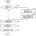
- 5 is a flowchart illustrating an example of a flow of instruction information acquisition processing performed by the information processing apparatus according to the embodiment.
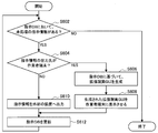
- 5 is a flowchart illustrating an example of a flow of instruction information output processing performed by the information processing apparatus according to the embodiment.
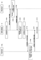
- It is a flowchart which shows an example of the flow of the ranch management process which the ranch management system which concerns on the embodiment performs.
- It is explanatory drawing which shows an example of the hardware constitutions of the information processing apparatus which concerns on this indication.
- the ranch management system 1 is an example of a system for managing a ranch where a cow B30 is raised.
- the cow B30 is only an example of livestock in a ranch management system including an information processing apparatus according to the present disclosure, and pigs, horses, birds, or the like may be applied as livestock.
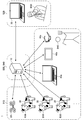
- FIG. 1 is an explanatory diagram illustrating an example of a system configuration of a ranch management system 1 according to the present embodiment.
- the ranch management system 1 includes an information processing device 10, a drone 20, a sensor 30, an operator terminal 40, and an administrator terminal 50.
- Each of the drone 20, the sensor 30, the worker terminal 40, and the administrator terminal 50 communicates with the information processing apparatus 10 via a wired or wireless information network.
- FIG. 1 one drone 20, three sensors 30, three worker terminals 40, and one administrator terminal 50 are shown for one information processing apparatus 10.
- the number of each of the drone 20, the sensor 30, the worker terminal 40, and the administrator terminal 50 that communicate with the apparatus 10 may be different from the number illustrated in FIG.
- the number of each of cow B30, worker B40, and manager B50 may be different from the number shown in FIG.
- the drone 20 is an example of a mobile object.
- the drone 20 is an unmanned air vehicle configured to be able to fly automatically based on a designated flight path.
- the drone 20 operates based on an operation command from the information processing apparatus 10, for example. Specifically, when the instruction information is output from the information processing apparatus 10 to the drone 20, the drone 20 operates based on the instruction information.
- the instruction information is information for instructing work related to the cow B30.
- the drone 20 can fly by, for example, four rotors, and can fly while moving up, down, or horizontally by controlling the rotation of each rotor.
- the flight path from the flight start position to the flight end position set in the drone 20 is indicated by, for example, a GNSS signal from a GNSS (Global Navigation Satellite System) satellite (for example, a GPS signal from a GPS (Global Positioning System) satellite).
- GNSS Global Navigation Satellite System
- GPS Global Positioning System
- the drone 20 may transmit various information to the information processing apparatus 10.
- the drone 20 may include an imaging device including a lens, an imaging device such as a CCD image sensor and a CMOS image sensor, a flash, and the like, and an image obtained by imaging processing by the imaging device is processed by the information processing device 10. May be sent to.
- the drone 20 may transmit an image showing the entire cow B30 obtained by imaging the cow B30 to the information processing apparatus 10. Further, the drone 20 may transmit an image showing the part obtained by imaging the part of the cow B30 to the information processing apparatus 10. The image transmitted from the drone 20 is used for processing for ranch management by the information processing apparatus 10. The image corresponds to state information indicating the state of the cow B30.
- the drone 20 may generate various types of information by performing image processing on an image obtained by imaging, and transmit the generated information to the information processing apparatus 10.
- the information generated by the image processing also corresponds to state information indicating the state of the cow B30.
- Sensor 30 is provided for each cow B30, detects various physical quantities related to the corresponding cow B30, and transmits the detection results.
- the sensor 30 may detect a physical quantity and transmit a detection result at a preset time. Further, when instruction information is output from the information processing apparatus 10 to the sensor 30, the sensor 30 may operate based on the instruction information.
- Sensor 30 may be attached to corresponding cow B30, for example.
- the detection result transmitted from the sensor 30 is received by the information processing device 10 and used for processing for ranch management by the information processing device 10.
- the detection result corresponds to state information indicating the state of the cow B30.
- the sensor 30 may be mounted on the drone 20, and in that case, the drone 20 can transmit the detection result obtained by the detection by the sensor 30 to the information processing apparatus 10.
- the information transmitted as a detection result from the sensor 30 includes physical condition information related to the physical condition of the cow B30, for example.
- the physical condition information includes, for example, information indicating the pulse rate, sweating amount, body temperature, body weight, volume, blood pressure, or skin condition of the cow B30.
- the pulse rate, sweat volume, body temperature, body weight, volume, blood pressure, and skin condition of the cow B30 can detect, for example, the pulse rate, sweat volume, body temperature, body weight, volume, blood pressure, and skin condition, respectively, as the sensor 30. It can be detected by applying a sensor.
- the information transmitted as a detection result from the sensor 30 may include behavior information related to the behavior of the cow B30.
- the behavior information may include information indicating which behavior the cow B30 is performing.
- the behavior of the cow B30 that can be detected by the sensor 30 includes, for example, mastication, vocalization, movement, excretion, or sleep.
- the behavior performed by the cow B30 is, for example, as the sensor 30, a sound sensor that can detect voice, an odor sensor that can detect odor, a GPS receiver that can detect the position of the cow B30, and a movement of the cow B30. It can be detected by using some or all of an acceleration sensor, a gyro sensor, and a geomagnetic sensor.
- the behavior information may include detailed information about the behavior detected as the behavior performed by the cow B30.
- the sensor 30 can acquire, for example, the speed of mastication, the content of the uttered voice, the moving speed, the frequency of excretion, or the frequency of sleep as the detailed information. Further, the detailed information can be detected by using the above-described sensor as the sensor 30.
- action information may be generated by the drone 20 performing imaging and image processing of the obtained image.
- the action information generated from the drone 20 is transmitted to the information processing apparatus 10.
- the drone 20 may generate information indicating which action the cow B30 is performing by performing imaging of the entire cow B30 and image processing of the obtained image.
- the drone 20 performs imaging of the mouth of the cow B30 and image processing of the obtained image, so that detailed information on mastication or vocalization can be generated.
- the drone 20 can generate detailed information about the movement of the cow B30 by performing imaging of the leg of the cow B30 and image processing of the obtained image.
- the information transmitted as a detection result from the sensor 30 may include position information indicating the position of the cow B30.
- the position of the cow B30 can be detected by applying a GPS receiver as the sensor 30, for example.
- the position information may include information indicating a range in which the cow B30 has moved within a predetermined time. The information can be calculated from the movement history of the cow B30.
- the drone 20 may generate position information by performing imaging of the entire cow B30 and image processing of the obtained image.
- the position information may be generated from the drone 20 to the information processing apparatus 10.
- Location information may be transmitted.
- the senor 30 may directly transmit the detected physical quantity as a detection result to the information processing apparatus 10, and information obtained by performing arithmetic processing on the detected physical quantity to the information processing apparatus 10 as a detection result. You may send it.
- the worker terminal 40 is an example of a communication device used mainly by the worker B40 in order to notify the instruction information output from the information processing device 10 to the ranch worker B40 who is a user.
- the worker terminal 40 has, for example, a function of communicating with an external device, a function of displaying a screen, a function of outputting sound, and a function of receiving an input from the worker B40.
- the above functions of the worker terminal 40 may be realized by various devices.
- FIG. 1 illustrates an example in which a personal computer, a smartphone, and a head mounted display are applied as the worker terminals 40a, 40b, and 40c, respectively.
- the worker terminal 40 notifies the instruction information to the worker B40, for example, by displaying the received instruction information.
- the worker terminal 40c which is a head-mounted display, is used in a state of being mounted on the head of the worker B40.
- the worker terminal 40c can display a screen superimposed on at least a part of the field of view of the worker B40.
- the worker terminal 40c may superimpose and display the received instruction information on at least a part of the field of view of the worker B40.
- the notification of the instruction information to the worker B40 by the worker terminal 40 may be realized by a method other than the screen display.
- the worker terminal 40 may notify the worker B40 of the instruction information by outputting the received instruction information as a voice.
- the worker terminal 40 may transmit information input by the worker B40 to the information processing apparatus 10.
- the worker terminal 40 may include, for example, at least one of a mouse, a keyboard, a touch panel, a button, a microphone, a switch, and a lever as an input device that receives input from the worker B40.
- the worker terminal 40 may include a device that can determine the gesture of the worker B40 in order to accept the gesture of the worker B40 as an input.
- the worker terminal 40 may transmit state information such as physical condition information of the cow B30 input by the worker B40 to the information processing apparatus 10. The information transmitted from the worker terminal 40 is used for processing for ranch management by the information processing apparatus 10.
- the manager terminal 50 is mainly used by the ranch manager B50 in order to input work information indicating work instructed to the device such as the drone 20 or the worker terminal 40.
- the administrator terminal 50 has, for example, a function of communicating with an external device, a function of displaying a screen, a function of outputting sound, and a function of receiving an input from the administrator B50.
- the above functions of the administrator terminal 50 can be realized by, for example, a personal computer, a smartphone, or a head mounted display.
- the administrator terminal 50 may display an input screen for accepting input of work information. For example, the administrator terminal 50 displays state information indicating the state of the cow B30 received from the information processing apparatus 10 on the input screen. Thereby, the manager B50 can determine an appropriate operation according to the actual state of the cow B30. The administrator B50 inputs work information based on the state information. Then, the administrator terminal 50 transmits the work information input based on the state information to the information processing apparatus 10. The work information is used for processing for ranch management by the information processing apparatus 10.
- the administrator terminal 50 may display the virtual space in association with the position of the cow B30 in the real space and the position of the cow B30 in the virtual space, for example. Thereby, the administrator B50 can determine the work by a more intuitive operation. Moreover, the manager B50 can determine a more appropriate work based on the position information of the cow B30.
- the input of the work information to the administrator terminal 50 by the administrator B50 may be realized by an operation via the input screen, or may be realized by another method.
- the administrator terminal 50 may include at least one of a mouse, a keyboard, a touch panel, a button, a microphone, a switch, and a lever as an input device that receives an input from the administrator B50.
- the administrator terminal 50 may include a device that can determine the gesture of the administrator B50 in order to accept the gesture of the administrator B50 as an input.
- the information processing apparatus 10 performs various processes for ranch management. Specifically, the information processing apparatus 10 controls the operation of external apparatuses such as the drone 20 and the sensor 30 and the display of the screen by the worker terminal 40 and the administrator terminal 50 for ranch management. For example, the information processing apparatus 10 causes the administrator terminal 50 to display state information received from the drone 20, the sensor 30, or the worker terminal 40. Further, the information processing apparatus 10 acquires work information input by the administrator B50 based on the state information from the administrator terminal 50. Further, the information processing apparatus 10 outputs instruction information for instructing the work indicated by the work information to the drone 20, the sensor 30, or the worker terminal 40. Thereby, the work related to the cow B30 is executed by the drone 20, the sensor 30 or the worker B40.
- the information processing apparatus 10 controls the operation of external apparatuses such as the drone 20 and the sensor 30 and the display of the screen by the worker terminal 40 and the administrator terminal 50 for ranch management. For example, the information processing apparatus 10 causes the administrator terminal 50 to display state information received from the drone 20, the sensor 30, or the worker terminal 40. Further
- the information processing apparatus 10 controls display of state information indicating the state of the cow B30, acquires work information indicating work related to the cow B30 input based on the state information, and Instruction information for instructing the work indicated by the information is output. Thereby, execution of an appropriate operation according to the actual state of the cow B30 can be realized while reducing the human burden. Therefore, according to the information processing apparatus 10 according to the present embodiment, the management of the cow B30 can be made more efficient. Details of the information processing apparatus 10 will be described later.
- FIG. 2 is a conceptual diagram for explaining a functional configuration of the ranch management system 1 according to the present embodiment.
- the functions of the ranch management system 1 can be realized by a real space working unit 910, a virtual space operation unit 920, a system control unit 930, and a storage unit 940.
- the real space working unit 910 has a function of executing work related to the cow B30 in the real space of the ranch.
- the above functions of the real space working unit 910 are realized by, for example, the drone 20, the sensor 30, the worker terminal 40, and the worker B40 illustrated in FIG.
- the virtual space operation unit 920 has a function of determining a work to be executed by the real space working unit 910 using a virtual space corresponding to the real space of the ranch.
- the functions of the virtual space operation unit 920 are realized by, for example, the administrator terminal 50 and the administrator B50 illustrated in FIG.
- the system control unit 930 controls the real space working unit 910 and the virtual space operation unit 920. Specifically, the system control unit 930 controls execution of work in the real space work unit 910 and display of a screen in the virtual space operation unit 920.
- the storage unit 940 stores data referred to for various processes in the system control unit 930. The data stored in the storage unit 940 can be rewritten by the system control unit 930.
- the above functions of the system control unit 930 and the storage unit 940 are realized by the information processing apparatus 10 illustrated in FIG. 1, for example. Note that the functions of the system control unit 930 and the storage unit 940 may be realized by a plurality of devices. Details of the information processing apparatus 10 will be described later.
- the system control unit 930 may use an augmented reality GUI (Graphical User Interface) in the control of the real space working unit 910.
- the augmented reality GUI is a GUI for presenting the sense that the real world is expanded to the worker B40.
- the augmented reality GUI is used when the function of the real space working unit 910 is realized by the worker terminal 40c and the worker B40 which are head mounted displays.
- the worker terminal 40c may superimpose and display the augmented reality GUI including the instruction information on at least a part of the field of view of the worker B40.
- the instruction information is notified to the worker B40 by the augmented reality GUI, and the worker B40 can perform the work corresponding to the instruction information. Details of the screen displayed by the worker terminal 40c will be described later.
- the system control unit 930 may use a virtual space GUI (Graphical User Interface) in the control of the virtual space operation unit 920.
- the virtual space GUI is a GUI for presenting a virtual world with a sense of reality to the administrator B50 and accepting operations by the administrator B50.
- the administrator terminal 50 may display a virtual space GUI including state information indicating the state of the cow B30. Thereby, the administrator B50 can determine the work to be executed by the real space working unit 910 by a more intuitive operation. Details of the screen displayed by the administrator terminal 50 will be described later.
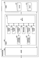
- FIG. 3 is an explanatory diagram illustrating an example of a functional configuration of the information processing apparatus 10 according to the present embodiment.
- the information processing apparatus 10 includes a communication unit 200, a storage unit 400, and a control unit 600.
- the communication unit 200 communicates with a device outside the information processing apparatus 10. Specifically, the communication unit 200 receives various information transmitted from the drone 20, the sensor 30, the worker terminal 40, and the administrator terminal 50, and outputs it to the storage unit 400 and the control unit 600. More specifically, the communication unit 200 receives, as state information indicating the state of the cow B30 from the drone 20, a captured image or information generated by performing image processing on the image. In addition, the communication unit 200 receives a detection result as state information from the sensor 30. Further, the communication unit 200 receives state information such as physical condition information input from the worker terminal 40 by the worker B40. Moreover, the communication part 200 receives the work information which shows the work relevant to the cow B30 input based on state information from the administrator terminal 50. As described above, the communication unit 200 corresponds to an acquisition unit according to the present disclosure that acquires work information indicating work related to the cow B30 input based on the state information.
- the communication unit 200 transmits various types of information to external devices such as the drone 20, the sensor 30, the worker terminal 40, and the administrator terminal 50 based on the operation command from the control unit 600. Thereby, the operation of external devices such as the drone 20 and the sensor 30 and the display of the screen by the worker terminal 40 and the administrator terminal 50 are controlled.
- the storage unit 400 stores data referred to for various processes in the information processing apparatus 10. Specifically, the storage unit 400 includes image data used for controlling display of images by the worker terminal 40 and the administrator terminal 50 performed by the control unit 600, a prediction model used for prediction processing performed by the control unit 600, and Various information input from the communication unit 200 is stored.
- the storage unit 400 stores a state DB (database) 410 and an instruction DB (database) 420.
- the state DB 410 the time at which the state information is acquired is associated with the state information.
- the instruction DB 420 the time when the instruction information is output is associated with the instruction information. Details of the state DB 410 and the instruction DB 420 will be described later.
- the control unit 600 includes a DB (database) operation unit 610, a state information generation unit 620, a virtual space GUI generation unit 630, an administrator terminal display control unit 640, a work information generation unit 650, and an instruction information generation unit 660.
- the DB operation unit 610 reads data from the state DB 410 and the instruction DB 420 stored in the storage unit 400 and registers data in the state DB 410 and the instruction DB 420.
- the DB operation unit 610 outputs the read data to the state information generation unit 620, the virtual space GUI generation unit 630, the work information generation unit 650, the instruction information generation unit 660, the augmented reality GUI generation unit 670, and the drive control unit 690. To do.
- the DB operation unit 610 updates the state DB 410 and the instruction DB 420 by registering the acquired state information and instruction information in the state DB 410 and the instruction DB 420, respectively.
- the history of the state of the cow B30 and the history of work instructed for the cow B30 can be accumulated as records. Therefore, since it is possible to investigate the relationship between the state of the cow B30 and the work instructed for the cow B30, it is possible to carry out improvement activities such as improving the efficiency of work on the ranch.
- the state information generation unit 620 Based on the first state information included in the state information, the state information generation unit 620 generates second state information that is state information indicating a state different from the state corresponding to the first state information.
- state information such as detection results transmitted from the drone 20, the sensor 30, or the worker terminal 40 is acquired by the communication unit 200, and then input to the storage unit 400 and registered in the state DB 410.
- the state information generation unit 620 generates second state information based on the state information registered in the state DB 410 corresponding to the first state information. Then, the state information generation unit 620 may cause the DB operation unit 610 to register the second state information in the state DB 410 by outputting the generated second state information to the DB operation unit 610.
- the information processing apparatus 10 can also acquire the state information by generating the second state information by the state information generation unit 620.
- the generation of the second state information by the state information generation unit 620 may be performed with the first state information input from the communication unit 200 to the storage unit 400 registered in the state DB 410 as a trigger. . In addition, the generation of the second state information by the state information generation unit 620 may be performed with a predetermined time elapsed as a trigger.
- the state information generation unit 620 generates information indicating whether the cow B30 is in estrus as the second state information based on information related to the utterance of the cow B30 corresponding to the first state information. Also good.
- the state information generation unit 620 may cause the cow B30 to have a disease as the second state information based on the information related to the chewing of the cow B30 corresponding to the first state information and the information indicating the body temperature. Information indicating whether or not there may be generated.
- the state information about more various states of the cow B30 can be presented to the manager B50.
- the state information generation unit 620 may generate the second state information by predicting the second state information from the first state information using a prediction model learned in advance, for example.
- a prediction model for predicting the second state information from the first state information is constructed according to an existing algorithm such as boosting or support vector machine.
- the prediction model is stored in the storage unit 400.
- the state information generation unit 620 may specify the second state information based on the first state information by performing prediction using the prediction model.
- the state DB 410 may be in a data table format, for example.
- FIG. 4 is an explanatory diagram showing an example of the data table D10 in the state DB 410.
- Various data can be registered in the data table D10 by the DB operation unit 610.
- the time at which the state information is acquired, the state information, and other various information are associated with each row.
- start time and “end time” indicate the time at which acquisition of the state information is started and ended, respectively.
- acquisition of state information means acquisition of state information by the drone 20, the sensor 30, or the worker terminal 40, or acquisition of state information by generation of second state information performed by the state information generation unit 620.
- acquisition location indicates the location where the state information is acquired for the state information such as the detection result acquired by the drone 20, the sensor 30, or the worker terminal 40.
- cow ID indicates the ID of cow B30 corresponding to the state information.
- acquisition means indicates a means used in acquisition of state information.
- “Means details” indicates more detailed information of the obtaining means.
- detailed status indicates more detailed information of the status information.
- the row corresponding to the region G10 indicates state information indicating a state of “slightly high heat” for the cow B30 having the cow ID “0263”.
- the state information is acquired by the drone A corresponding to the drone 20 in FIG. 1 using the infrared camera.
- a temperature file that is information about the detected temperature is shown.
- the status information is acquired by the drone A from 16:29 on December 14, 2015 to 17:52 on December 14, 2015.
- the address number corresponding to the place where the status information is acquired is “35.631166, 139.743612”.
- the generation of the second state information may be performed by an expert such as a veterinarian.
- a veterinarian or the like can input the second state information to the terminal by referring to the first state information registered in the state DB 410 by using a terminal that can communicate with the information processing apparatus 10. it can. Then, the input second state information can be transmitted from the terminal to the information processing apparatus 10 and acquired by the information processing apparatus 10.
- the second state information input by an expert such as a veterinarian may be information indicating that there is a possibility of illness, for example.
- information indicating that it is necessary to request the veterinarian to generate the second state information is information You may be comprised so that the operator of the processing apparatus 10 may be notified.
- the virtual space GUI generation unit 630 generates a virtual space GUI as information to be displayed on the administrator terminal 50 and outputs the virtual space GUI to the administrator terminal display control unit 640.
- the generated virtual space GUI is displayed on the administrator terminal 50 by the administrator terminal display control unit 640 controlling display of the screen by the administrator terminal 50. Thereby, a virtual world with a sense of reality can be presented to the administrator B50.
- the virtual space GUI generation unit 630 generates a virtual space GUI based on information stored in the storage unit 400. Specifically, the virtual space GUI generation unit 630 generates a virtual space GUI including state information indicating the state of the cow B30 based on the state DB 410. Further, the virtual space GUI generation unit 630 generates a virtual space GUI by associating the position of the cow B30 in the real space with the position of the cow B30 in the virtual space GUI based on the position information indicating the position of the cow B30. May be. The virtual space GUI generation unit 630 may generate a virtual space GUI corresponding to the time selected by the administrator B50 and output the generated virtual space GUI to the administrator terminal display control unit 640.
- the virtual space GUI generation unit 630 may generate a virtual space GUI using an operation command from the administrator terminal display control unit 640 as a trigger. Further, the virtual space GUI generation unit 630 may generate the virtual space GUI by using the state DB 410 updated by the DB operation unit 610 as a trigger. Further, the virtual space GUI generation unit 630 may generate the virtual space GUI by using a predetermined time as a trigger. The details of the virtual space GUI generated by the virtual space GUI generation unit 630 and displayed on the administrator terminal 50 will be described later.
- the administrator terminal display control unit 640 controls screen display by the administrator terminal 50. Specifically, the administrator terminal display control unit 640 causes the administrator terminal 50 to transmit information for displaying various screens on the administrator terminal 50 to the administrator terminal 50. Control the display of the screen. For example, the administrator terminal display control unit 640 displays the virtual space GUI generated by the virtual space GUI generation unit 630 on the administrator terminal 50. Further, the administrator terminal display control unit 640 may control display of a screen by the administrator terminal 50 in accordance with an operation input from the administrator B50.
- the administrator terminal display control unit 640 causes the administrator terminal 50 to display state information indicating the state of the cow B30. Specifically, the administrator terminal display control unit 640 causes the administrator terminal 50 to display the virtual space GUI generated by the virtual space GUI generation unit 630. Here, the virtual space GUI displayed on the administrator terminal 50 includes state information indicating the state of the cow B30. As described above, the administrator terminal display control unit 640 corresponds to a display control unit that controls display of state information indicating the state of livestock.
- the administrator terminal display control unit 640 may display the virtual space on the administrator terminal 50 by associating the position of the cow B30 in the real space with the position of the cow B30 in the virtual space. Specifically, the administrator terminal display control unit 640 manages the virtual space GUI generated by the virtual space GUI generation unit 630 in association with the position of the cow B30 in the real space and the position of the cow B30 in the virtual space GUI. You may display on person terminal 50. Thereby, the administrator B50 can determine the work instructed to the device such as the drone 20 or the worker B40 by a more intuitive operation. Moreover, the manager B50 can determine a more appropriate work based on the position information of the cow B30.
- a screen displayed by the administrator terminal 50 will be described.
- FIG. 5 is an explanatory diagram showing an example of the overhead view screen E12 displayed on the administrator terminal 50.
- the bird's-eye view screen E12 is a virtual space GUI showing a virtual space when the ranch is viewed from above.
- the administrator terminal display control unit 640 may cause the administrator terminal 50 to display the virtual space viewed from above.
- state information and position information of the cow B30 on the ranch are mainly displayed.
- a cow image F17 indicating the position of the cow B30 is displayed superimposed on a ranch image F20 indicating the appearance of the ranch.
- the ranch image F20 may include an image showing an object fixed to the land in the ranch such as a building, a vegetation, and a road.
- an image showing the positions of the drone 20 and the worker B40 may be displayed on the overhead view screen E12.
- information indicating whether or not work related to the cow B30 can be performed may be displayed as information indicating the operating status of the drone 20 and the worker B40.
- state information indicating the state of the cow B30 is displayed.
- the cow state icon F18 indicating the state of the cow B30 is displayed in the vicinity of the cow image F17 of the corresponding cow B30.
- the administrator terminal display control unit 640 changes the state of the cow B30 to the administrator B50 by changing the type of the cow state icon F18 displayed on the overhead view screen E12 according to the state of the cow B30. You may present.
- the administrator terminal display control unit 640 may change the color of the displayed cow state icon F18 according to the state of the cow B30. Moreover, the administrator terminal display control part 640 may change the shape of the displayed cow state icon F18 according to the state of the cow B30.
- a state icon type area F16 indicating the correspondence between the type of the cow state icon F18 and the state of the cow B30 may be provided on the right side of the center.
- the hatched shade difference in the cow state icon F18 indicates a difference in the state of the cow B30.
- a latest state acquisition button F14 for displaying the latest state of the cow B30 on the administrator terminal 50 may be displayed in the upper right part.
- the administrator terminal display control unit 640 causes the administrator terminal 50 to display the virtual space GUI generated most recently by the virtual space GUI generation unit 630.
- the status information indicating the latest status of the cow B30 can be presented to the administrator B50.
- position information indicating the latest position of the cow B30 can be presented to the manager B50.
- a time slider F12 that is a slider for selecting a time corresponding to the virtual space GUI to be displayed on the administrator terminal 50 is displayed at the top.
- the administrator terminal display control unit 640 is selected by the administrator B50.
- a virtual space GUI corresponding to the time is displayed on the administrator terminal 50.
- the administrator terminal display control unit 640 instructs the virtual space GUI generation unit 630 to generate a virtual space GUI corresponding to the selected time.
- the administrator terminal display control unit 640 acquires the virtual space GUI generated by the virtual space GUI generation unit 630 and causes the administrator terminal 50 to display the virtual space GUI.
- the administrator B50 may be able to select a past or future time using the time slider F12.
- the virtual space GUI generation unit 630 uses the information corresponding to the selected time in the state DB 410, for example, and uses the virtual space GUI corresponding to the selected time. May be generated.
- the virtual space GUI generation unit 630 generates a virtual space GUI corresponding to the selected time using, for example, a prediction model learned in advance. Also good.
- the administrator terminal display control unit 640 may switch the virtual space corresponding to each of a plurality of times to be displayed on the administrator terminal 50. Thereby, the administrator B50 can determine the work instructed to the device such as the drone 20 or the worker B40 based on the history of the state of the cow B30.
- the virtual space GUI generation unit 630 selects the selected time in the state DB 410.
- the virtual space GUI may be generated using information corresponding to different times. Specifically, the virtual space GUI generation unit 630 generates a virtual space GUI by linearly interpolating information corresponding to the time immediately before and immediately after the selected time among the information included in the state DB 410. Also good. Further, the virtual space GUI generation unit 630 may generate the virtual space GUI based on information corresponding to the time immediately before the selected time among the information included in the state DB 410.
- a viewpoint icon F22 indicating a viewpoint on a first-person viewpoint screen described later and a view icon F23 indicating a field of view may be displayed.
- the administrator terminal display control unit 640 may control the display of the viewpoint icon F22 and the view icon F23 according to the operation input from the administrator B50.
- the administrator B50 can set the viewpoint on the first-person viewpoint screen described later by adjusting the position of the viewpoint icon F22 on the overhead viewpoint screen E12.
- the administrator B50 can set the field of view by adjusting the direction of the viewpoint icon F22 on the overhead viewpoint screen E12 and adjusting the line-of-sight direction on the first-person viewpoint screen described later.
- the administrator terminal display control unit 640 displays the bird's-eye view screen E12 showing the virtual space when the ranch shown in FIG. 5 is viewed from above, and the ranch shown in FIG.
- the display of the first-person viewpoint screen E14 showing the virtual space viewed from the ground may be switchable.
- the bird's-eye view screen E12 the state of the cow B30 over a wide area in the ranch can be confirmed as compared with the first-person view screen E14.
- the first-person viewpoint screen E14 more detailed information about each cow B30 can be confirmed and work information can be input compared to the overhead view screen E12. Details of the first-person viewpoint screen E14 will be described below.
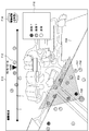
- FIG. 6 is an explanatory diagram showing an example of the first-person viewpoint screen E14 displayed on the administrator terminal 50.
- the first person viewpoint screen E14 is a virtual space GUI showing a virtual space when the ranch is viewed from the ground.
- the administrator terminal display control unit 640 may cause the administrator terminal 50 to display the virtual space viewed from the ground.
- the state information and position information of the cow B30 reflected in the field of view indicated by the field of view icon F23 on the bird's eye viewpoint screen E12 are mainly displayed.
- a cow image F17 indicating the position of the cow B30 is displayed superimposed on the ranch image F20 indicating the appearance of the ranch.
- an image indicating the positions of the drone 20 and the worker B40 may be displayed. Since the viewpoint is located on the ground on the first person viewpoint screen E14, an image closer to the sight reflected in the field of view of the worker B40 can be presented to the manager B50 as compared to the overhead view viewpoint screen E12.
- a message F28 related to the state indicated by the cow state icon F18 may be displayed in the vicinity of the cow state icon F18.
- the message F28 may be more detailed information on the state indicated by the cow state icon F18.
- the message F28 may be information used to generate state information corresponding to the cow state icon F18.
- the state information generation unit 620 determines that the cow B30 is based on the first state information indicating that the body temperature of the cow B30 is high fever, coughing, and nasal discharge.
- the first state information may be displayed as a message F28 as shown in FIG.
- the cow state icon F18 and the message F28 corresponding to the cow state icon F18 are displayed in the vicinity of the part corresponding to the message F28 in the cow image F17. Also good. Specifically, as shown in FIG. 6, a cow status icon F18 indicating that there is a possibility of suffering from a disease and a message F28 indicating coughing and nasal discharge are displayed It may be displayed near the nose in the image F17.
- the first person viewpoint screen E14 may correspond to an input screen for accepting an input by the administrator B50 regarding work information indicating work instructed to an apparatus such as the drone 20 or the worker terminal 40.
- the function as the input screen of the first person viewpoint screen E14 is realized by, for example, the work selection window F26.
- the work selection window F26 displays, for example, a cow B30 corresponding to the work in order for the administrator B50 to input work information indicating the work instructed to the device such as the drone 20 or the worker B40. It is provided in the vicinity of the cow image F17 shown.
- a plurality of work candidates related to the cow B30 generated based on the state information may be displayed. For example, in the work selection window F26, as shown in FIG. 6, “move to cowshed”, “administration of vitamin preparation”, and “artificial insemination” are displayed as work candidates. In the work selection window F26, an estimated time required for the work may be displayed for each work candidate. Note that, in the work selection window F26, an area indicating a work candidate that cannot be executed due to the attribute of the cow B30, the state of equipment in the ranch, or the like may be grayed out. In the work candidates displayed in the work selection window F26, work information indicating the work selected by the administrator B50 is transmitted from the administrator terminal 50 to the information processing apparatus 10 as work information input based on the state information. Is done.
- a plurality of candidates for work related to cattle B30 are generated based on the state information by the administrator terminal display control unit 640, for example.
- the administrator terminal display control unit 640 may cause the administrator terminal 50 to display a plurality of work candidates related to the cow B30 generated based on the state information.
- the manager B50 can more easily determine the work instructed to the device such as the drone 20 or the worker B40.
- a work selection window F26 corresponding to the selected cow B30 may be displayed triggered by the selection of the cow B30 by the administrator B50.
- the name of the selected cow B30 and the number of months after birth may be displayed.
- the work selection window F26 may have a balloon shape indicating the selected cow B30 as shown in FIG.
- the work information may be input by the administrator B50.
- the administrator B50 may determine work to be instructed to the device such as the drone 20 or the worker B40 based on the displayed state information of the cow B30, and may input work information indicating the work. In such a case, the work selection window F26 may not be displayed.
- the administrator B50 may be configured to be able to make a call with the worker B40 using the overhead view screen E12 and the first person view screen E14. For example, when an image showing the worker B40 is displayed on the overhead view viewpoint screen E12 or the first person viewpoint screen E14, when the administrator B50 selects an image showing the worker B40, the administrator terminal 50 and the worker When the terminal 40 starts communication, the manager B50 and the worker B40 may be able to talk.
- images such as the ranch image F20 displayed on the overhead viewpoint screen E12 and the first person viewpoint screen E14 may be generated using a three-dimensional model stored in the storage unit 400 in advance. Further, the three-dimensional model may be generated or updated based on an image captured by the drone 20. Moreover, a part of the overhead view viewpoint screen E12 and the first person viewpoint screen E14 may be configured by an image captured by the drone 20 or the like.
- the administrator terminal display control unit 640 displays a screen about the outdoors on the ranch on the administrator terminal 50 has been described. However, the administrator terminal display control unit 640 manages the screen about the indoors on the ranch. You may display on person terminal 50. Note that the administrator terminal display control unit 640 may control the display of the screen by the administrator terminal 50 for one or both of indoor and outdoor in the ranch.
- the administrator terminal display control unit 640 may display the virtual space GUI on the administrator terminal 50 using an operation input from the administrator B50 as a trigger. In that case, the administrator terminal display control unit 640 may instruct the virtual space GUI generation unit 630 to generate a virtual space GUI in response to an operation input from the administrator B50. Further, the administrator terminal display control unit 640 may update the virtual space GUI displayed on the administrator terminal 50, triggered by the generation of the virtual space GUI by the virtual space GUI generation unit 630. In addition, the administrator terminal display control unit 640 may update the virtual space GUI displayed on the administrator terminal 50, triggered by the elapse of a predetermined time.
- the work information generation unit 650 generates work information based on the state information and outputs the work information to the instruction information generation unit 660. For example, the work information generation unit 650 may acquire the state information included in the state DB 410 via the DB operation unit 610.
- the information processing apparatus 10 includes a manual mode in which input of work information is performed by the administrator B50 using the administrator terminal 50, and input of work information is not performed by the operation of the administrator B50.
- the automatic mode performed by may be configured to be switchable. Switching between the manual mode and the automatic mode may be performed, for example, in response to an operation input from the administrator B50 to the administrator terminal 50. Information indicating that the mode has been switched is transmitted from the administrator terminal 50 to the information processing apparatus 10.
- the generation of work information by the work information generation unit 650 is specifically performed when the input of work information is in the automatic mode.
- the information processing apparatus 10 In the manual mode, as described above, input of work information by the administrator B50 is accepted on the first-person viewpoint screen E14, and the work information is transmitted from the administrator terminal 50 to the information processing apparatus 10. In this case, the information processing apparatus 10 outputs instruction information for instructing the work indicated by the work information transmitted from the administrator terminal 50.
- the work information generation unit 650 in the information processing apparatus 10 generates work information based on the state information. In this case, the information processing apparatus 10 outputs instruction information for instructing the work indicated by the work information generated by the work information generation unit 650. The details of the processing related to the output of the instruction information will be described later.
- the work information is generated by the work information generation unit 650 based on the state information, so that the burden of inputting the work information by the administrator B50 can be omitted. Thereby, the human burden in management of cattle B30 can be reduced.
- the work information generation unit 650 may generate the work information by, for example, predicting the work information from the state information using a prediction model learned in advance.
- a prediction model learned in advance In the prior learning process, many pairs of work information input by the administrator B50 and state information corresponding to the work information are prepared.
- the work information and state information prepared here correspond to teacher information and student information in supervised learning, respectively.
- a prediction model for predicting work information from state information is constructed.
- the prediction model is stored in the storage unit 400.
- the work information generation unit 650 may specify the work information based on the state information by performing prediction using the prediction model.
- the generation of work information by the work information generation unit 650 may be performed with the state DB 410 updated by the DB operation unit 610 as a trigger. Further, the generation of work information by the work information generation unit 650 may be performed with a predetermined time elapse as a trigger.
- the instruction information generation unit 660 generates instruction information for instructing work to an external device such as the drone 20 and the worker B40. For example, the instruction information generation unit 660 generates instruction information for instructing the work indicated by the work information based on the work information indicating the work related to the cow B30. The instruction information generation unit 660 may generate instruction information for instructing the work indicated by the work information, triggered by the information processing apparatus 10 receiving the work information input by the administrator B50. When the work information is generated by the work information generation unit 650, the instruction information generation unit 660 generates instruction information for instructing the work indicated by the work information using the generation of the work information as a trigger. May be.
- the instruction information generation unit 660 may cause the DB operation unit 610 to register the instruction information in the instruction DB 420 by outputting the generated instruction information to the DB operation unit 610.
- the instruction information generation unit 660 determines an instruction target that is an object to be instructed to work, and outputs information indicating the determined instruction target to the DB operation unit 610, thereby indicating the instruction target to the instruction DB 420.
- the DB operation unit 610 may register information. Thereby, the instruction information is associated with the information indicating the instruction target.
- the instruction information generation unit 660 may determine an instruction target that is an object to be instructed based on, for example, the distance between the worker B40 and each of the external devices and the cow B30 corresponding to the work information. Specifically, in the work selection window F26 illustrated in FIG. 6, when “move to the barn” is selected as the work related to the cow B30 by the administrator B50, the instruction information generation unit 660 displays the cow information. The operator B40 located closest to B30 may be determined as an instruction target. In that case, the instruction information for instructing the work to move the cow B30 to the barn is associated with the information indicating that the instruction target is the worker B40.
- the instruction information generation unit 660 may determine an instruction target based on the operating statuses of the worker B40 and the external device. Specifically, when “move to the barn” is selected as the work related to the cow B30 by the manager B50, the work can be executed within a predetermined distance from the cow B30. When the worker B40 does not exist, the drone 20 may be determined as an instruction target. In that case, the instruction information for instructing the work of moving the cow B30 to the barn and the information indicating that the instruction target is the drone 20 are associated with each other.
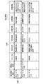
- the instruction DB 420 may be in a data table format, for example.
- FIG. 7 is an explanatory diagram showing an example of the data table D20 of the instruction DB 420.
- Various data can be registered in the data table D20 by the DB operation unit 610.
- the time at which the instruction information is output, the instruction information, and various other information are linked in each row.
- “instruction start time” and “work completion time” indicate the time when the output of the instruction information is started and the time when the work corresponding to the instruction information is completed.
- the information processing apparatus 10 may end the output of the instruction information when receiving information indicating that the work corresponding to the instruction information is completed.
- the “work completion time” indicates the time when the output of the instruction information is finished.
- the “status” indicates the progress state of the instructed work.
- the “instructing subject” indicates a subject who has input work information indicating the instructed work.
- the instruction information generation unit 660 corresponds to the instruction subject.
- “instruction target” indicates a target for which work is instructed.
- the instruction information includes, for example, “work target”, “work type”, and “work details”.
- “Work target” indicates the cow B30 corresponding to the designated work.
- the “work type” indicates the type of work to be instructed.
- “Work details” indicates detailed information of the designated work.
- the row corresponding to the region G20 indicates instruction information for instructing the work of moving the cow B30 having the cow ID “0134” to the barn.
- an instruction target that is an object for which the work is instructed is a farm worker A corresponding to the worker B40 in FIG. Therefore, the output destination of the instruction information is the worker terminal 40 used by the farm worker A.
- the instructing subject is the farm manager A corresponding to the manager B50 in FIG.
- the output of the instruction information has started at 15:35 on December 14, 2015, indicating that the work corresponding to the instruction information has not been completed and is in an unprocessed state. .
- the instruction information generation unit 660 generates instruction information regardless of whether the information processing apparatus 10 has received the work information input by the administrator B50 and that the work information generation unit 650 has generated the work information. May be.
- the instruction information generation unit 660 may generate instruction information for instructing a preset work using a predetermined time as a trigger.
- the instruction information generation unit 660 may generate instruction information for instructing the sensor 30 to detect a physical quantity every 10 minutes.
- the instruction information generation unit 660 may generate instruction information for instructing the drone 20 to image a predetermined place every hour.
- the instruction information generation unit 660 generates instruction information for instructing the external device and the worker B40 to perform operations that the external device such as the drone 20 and the worker B40 perform in cooperation with each other. May be.
- the augmented reality GUI generation unit 670 generates an augmented reality GUI as information to be displayed on the worker terminal 40 and outputs the augmented reality GUI to the worker terminal display control unit 680.
- the generated augmented reality GUI is displayed on the worker terminal 40c by the worker terminal display control unit 680 controlling display of the screen by the worker terminal 40c which is a head-mounted display. Thereby, it is possible to present to the worker B40 a sense that the real world has been expanded.
- the augmented reality GUI generation unit 670 generates an augmented reality GUI based on the information stored in the storage unit 400. Specifically, the augmented reality GUI generation unit 670 generates an augmented reality GUI including instruction information for instructing work based on the instruction DB 420. Further, the augmented reality GUI generation unit 670 generates an augmented reality GUI when the output destination of the instruction information is the worker terminal 40c that is a head-mounted display. The augmented reality GUI generation unit 670 generates an augmented reality GUI using, for example, the update of the instruction DB 420 by the DB operation unit 610 as a trigger. Details of the augmented reality GUI generated by the augmented reality GUI generation unit 670 and displayed on the worker terminal 40c will be described later.
- the worker terminal display control unit 680 controls display of the screen by the worker terminal 40. Specifically, the worker terminal display control unit 680 causes the worker terminal 40 to transmit information to the worker terminal 40 to display various screens on the worker terminal 40 to the worker terminal 40. Control the display of the screen. In addition, the worker terminal display control unit 680 may control the display of the screen by the worker terminal 40 in accordance with an operation input from the worker B40.
- the worker terminal display control unit 680 notifies the worker B40 of the instruction information by outputting the instruction information to the worker terminal 40 used by the worker B40.
- the instruction information is displayed on the worker terminal 40 that has received the instruction information. Thereby, notification of the instruction information to the worker B40 is realized. Therefore, the worker B40 can execute the work determined based on the state information without appropriately determining the work to be executed according to the actual state of the cow B30. Therefore, it is possible to appropriately manage the cow B30 while reducing the human burden in the confirmation of the actual state of the cow B30 by the worker B40 and the confirmation of the state of the entire ranch. Therefore, it is possible to make the management of the cow B30 more efficient.
- the worker terminal display control unit 680 corresponds to an output unit according to the present disclosure that outputs instruction information.
- the worker terminal display control unit 680 outputs the instruction information when the instruction DB 420 is updated by the DB operation unit 610 as a trigger.
- the notification of the instruction information to the worker B40 is not limited to the example realized by displaying the instruction information, and may be realized by, for example, outputting the instruction information by voice.
- the control unit 600 may include an audio output control unit that controls audio output by the worker terminal 40.
- the voice output control unit can correspond to an output unit that notifies the worker B40 of the instruction information by outputting the instruction information to the worker terminal 40.
- the worker terminal display control unit 680 may display the augmented reality GUI generated by the augmented reality GUI generation unit 670 on the worker terminal 40c that is a head-mounted display.
- the augmented reality GUI including the instruction information is superimposed and displayed on at least a part of the field of view of the worker B40.
- a screen displayed by the worker terminal 40c will be described.
- FIG. 8 is an explanatory diagram showing an example of the superimposed screen E20 displayed on the worker terminal 40.
- the superimposition screen E20 is an augmented reality GUI displayed so as to be superimposed on at least a part of the field of view of the worker B40 viewing the ranch from the ground.
- instruction information corresponding to the cow B30 in the real space reflected in the field of view of the worker B40 is mainly displayed.
- FIG. 8 shows a cow B30, a ranch B32, and a mountain B34 which is an example of the background of the ranch B32 in the real space reflected in the field of view of the worker B40.
- FIG. 8 shows an example in which the instruction information for instructing the operation of moving the cow B30 to the barn is displayed on the superimposed screen E20.
- a message F30, an object F32, and an arrow F34 are shown as the instruction information.
- the message F30 indicates details of work corresponding to the instruction information.
- the message F30 may have a balloon shape indicating the cow B30 corresponding to the instruction information.
- the object F32 is displayed in the vicinity of the cow B30 in order to indicate the cow B30 corresponding to the instruction information.
- An arrow F34 indicates the direction of the barn relative to the cow B30. In other words, the arrow F34 indicates the direction in which the cow B30 is moved in the operation corresponding to the instruction information.
- the worker B40 By displaying the augmented reality GUI including the instruction information superimposed on at least a part of the field of view of the worker B40, the worker B40 is in a state where the cow B30 in the real space corresponding to the instructed work is reflected in the field of view. Thus, the instruction information can be confirmed. Thereby, worker B40 can perform the work relevant to cow B30 more smoothly.
- the worker terminal display control unit 680 may control display of a screen by another type of worker terminal 40.
- the worker terminal display control unit 680 may control display of a screen by the worker terminal 40a that is a personal computer or the worker terminal 40b that is a smartphone.
- the worker terminal display control unit 680 may acquire the instruction information from the instruction DB 420 via the DB operation unit 610 and output the instruction information to the worker terminal 40, for example.
- the worker B40 When the work corresponding to the instruction information output by the worker terminal display control unit 680 is completed, the worker B40 inputs information indicating that the work is completed to the worker terminal 40. Thereby, the information is transmitted from the worker terminal 40 to the information processing apparatus 10.
- the worker terminal display control unit 680 ends the output of the instruction information, triggered by the information processing apparatus 10 receiving the information. Further, the DB operation unit 610 registers information indicating that the work corresponding to the instruction information is completed in the instruction DB 420.
- the drive control unit 690 controls the operation of an external device such as the drone 20 or the sensor 30. Specifically, the drive control unit 690 controls the operation of the external device by causing the communication unit 200 to transmit an operation command for controlling the operation of the external device to the external device. .
- the drive control unit 690 corresponds to an output unit that controls the execution of work by the external device by outputting the instruction information to the external device. For example, the drive control unit 690 outputs the instruction information with the instruction DB 420 updated by the DB operation unit 610 as a trigger.
- the external device whose execution of work is controlled by the drive control unit 690 may include the drone 20.
- the drive control unit 690 may control execution of work by the drone 20 by outputting the instruction information to the drone 20.
- the execution of the work determined based on the state information is realized by the drone 20.
- the drone 20 can perform operations such as guidance of the cow B30, detection of a physical quantity by the sensor 30 mounted on the drone 20, or imaging by an imaging device mounted on the drone 20 based on the instruction information. Therefore, in addition to the confirmation of the actual state of the cow B30 by the worker B40 and the confirmation of the state of the entire ranch, it is possible to appropriately manage the cow B30 while reducing the human burden in the work related to the cow B30. it can. Accordingly, the management of the cow B30 can be further improved.
- an external device whose execution is controlled by the drive control unit 690 may include the sensor 30.
- the drive control unit 690 corresponds to an output unit that controls execution of work by the sensor 30 by outputting instruction information to the sensor 30.
- the execution of the work determined based on the state information is realized by the sensor 30.
- the sensor 30 can execute a physical quantity detection operation based on the instruction information.
- the sensor 30 may further perform arithmetic processing on the detected physical quantity based on the instruction information. Therefore, in addition to the confirmation of the actual state of the cow B30 by the worker B40 and the confirmation of the state of the entire ranch, it is possible to appropriately manage the cow B30 while reducing the human burden in the work related to the cow B30. it can. Accordingly, the management of the cow B30 can be further improved.
- the external device whose execution of work is controlled by the drive control unit 690 may include devices other than the drone 20 and the sensor 30.
- a moving body such as an automatic traveling vehicle may be applied as the external device.
- the drive control unit 690 can control execution of work by the automatic traveling vehicle or the like by outputting the instruction information to the automatic traveling vehicle or the like.
- an external device such as the drone 20 or the sensor 30 transmits information indicating that the work is completed to the information processing apparatus 10.
- the drive control unit 690 ends the output of the instruction information with the information processing apparatus 10 receiving the information as a trigger. Further, the DB operation unit 610 registers information indicating that the work corresponding to the instruction information is completed in the instruction DB 420.
- FIG. 9 is a flowchart illustrating an example of a flow of instruction information acquisition processing performed by the information processing apparatus 10 according to the present embodiment. In addition, in FIG. 9, the flow of a process after acquisition of state information and registration to state DB410 is shown.
- the information processing apparatus 10 determines whether or not the input of work information is in the automatic mode (step S502). If it is determined that the input of work information is in the automatic mode (step S502 / YES), the process proceeds to step S508. On the other hand, when it is determined that the input of work information is not in the automatic mode (step S502 / NO), the virtual space GUI generation unit 630 generates a virtual space GUI including state information indicating the state of the cow B30 based on the state DB 410. It generates (step S504) and outputs it to the administrator terminal display control unit 640. Next, the administrator terminal display control unit 640 displays the virtual space GUI generated by the virtual space GUI generation unit 630 on the administrator terminal 50 (step S506).
- the work information is input to the administrator terminal 50 by the administrator B50 based on the state information, and is transmitted from the administrator terminal 50 to the information processing apparatus 10.
- the communication unit 200 acquires the work information (step S508). If it is determined that the input of the work information is in the automatic mode (step S502 / YES), the work information is acquired by the information processing apparatus 10 by being generated based on the state information by the work information generating unit 650. (Step S508).
- the instruction information generation unit 660 generates instruction information for instructing the work indicated by the work information based on the work information indicating the work related to the cow B30 (step S510).
- the DB operation unit 610 registers the instruction information input from the instruction information generation unit 660 in the instruction DB 420 (step S512), and the process illustrated in FIG. 9 ends.
- FIG. 10 is a flowchart illustrating an example of a flow of instruction information output processing performed by the information processing apparatus 10 according to the present embodiment. 10 shows the flow of processing after the instruction information is registered in the instruction DB 420 by the DB operation unit 610.
- the information processing apparatus 10 determines whether there is unprocessed instruction information in the instruction DB 420 (step S ⁇ b> 602). When it is determined in the instruction DB 420 that there is no unprocessed instruction information (step S602 / NO), the process illustrated in FIG. 10 ends. On the other hand, when it is determined that there is unprocessed instruction information in the instruction DB 420 (step S602 / YES), the information processing apparatus 10 determines whether the output destination of the instruction information is the worker terminal 40 (step). S604).
- the augmented reality GUI generation unit 670 includes the augmented reality including the instruction information for instructing the work based on the instruction DB 420.
- a GUI is generated (step S606) and output to the worker terminal display control unit 680.
- the worker terminal display control unit 680 displays the augmented reality GUI generated by the augmented reality GUI generation unit 670 on the worker terminal 40c, which is a head-mounted display (step S608). Thereby, notification of the instruction information to the worker B40 is realized.
- the worker terminal display control unit 680 includes, for example, a DB operation unit.
- the instruction information may be acquired from the instruction DB 420 via 610 and the instruction information may be output to the worker terminal 40.
- the process performed by the information processing apparatus 10 proceeds to the process of step S612 after the process of step S608.
- step S604 when it is determined that the output destination of the instruction information is not the worker terminal 40 (step S604 / NO), the drive control unit 690 sends the instruction information to an external device such as the drone 20 or the sensor 30. The data is output to the device (step S610). Thereby, execution of the work by the external device is realized.
- the communication unit 200 receives information indicating that the work has been completed from an external device such as the worker terminal 40 or the drone 20 that is the output destination of the instruction information. Then, the DB operation unit 610 updates the instruction DB 420 by registering the information in the instruction DB 420 (Step S612), and returns to the process of Step S602.
- FIG. 11 is a flowchart illustrating an example of the flow of ranch management processing performed by the ranch management system 1 according to the present embodiment.
- FIG. 11 shows an example of the flow of ranch management processing when the work information is input in the manual mode and the output destination of the instruction information is the worker terminal 40c corresponding to the head mounted display.
- the information processing apparatus 10 In the ranch management process, as illustrated in FIG. 11, first, the information processing apparatus 10 generates a virtual space GUI including state information indicating the state of the cow B30 (step S702). Then, the information processing apparatus 10 displays the generated virtual space GUI on the administrator terminal 50 (step S704). Next, the administrator terminal 50 acquires work information by an operation input by the administrator B50 (step S706). Then, the administrator terminal 50 transmits work information to the information processing apparatus 10 (step S708).
- the information processing apparatus 10 generates instruction information for instructing the work indicated by the work information based on the acquired work information (step S710). Then, the information processing apparatus 10 generates an augmented reality GUI including instruction information (step S712). Then, the information processing apparatus 10 displays the augmented reality GUI on the worker terminal 40c (step S714). Next, the worker terminal 40 displays the augmented reality GUI so as to be superimposed on at least a part of the field of view of the worker B40, thereby notifying the worker B40 of the instruction information (step S716). After the work is completed, the worker terminal 40 acquires information indicating that the work is completed by an operation input by the worker B40, and transmits the information to the information processing apparatus 10 (step S717). Next, the information processing apparatus 10 registers the information in the instruction DB 420 to update the instruction DB 420 (step S718), and returns to the process of step S702.
- FIG. 12 is an explanatory diagram illustrating an example of a hardware configuration of the information processing apparatus 10 according to the present disclosure.
- the information processing apparatus 10 includes a CPU (Central Processing Unit) 142, a ROM (Read Only Memory) 144, a RAM (Random Access Memory) 146, a bridge 148, a bus 150, and an interface. 152, an input device 154, an output device 156, a storage device 158, a drive 160, a connection port 162, and a communication device 164.
- a CPU Central Processing Unit
- ROM Read Only Memory
- RAM Random Access Memory
- the CPU 142 functions as an arithmetic processing unit and a control unit, and realizes the operation of each functional configuration in the information processing apparatus 10 in cooperation with various programs.
- the CPU 142 may be a microprocessor.
- the ROM 144 stores programs or calculation parameters used by the CPU 142.
- the RAM 146 temporarily stores programs used in the execution of the CPU 142 or parameters that change as appropriate in the execution.
- the CPU 142, the ROM 144, and the RAM 146 are connected to each other by an internal bus including a CPU bus.
- the input device 154 is an input means for an operator to input information such as a mouse, a keyboard, a touch panel, a button, a microphone, a switch, and a lever, and generates an input signal based on an input by the operator and outputs the input signal to the CPU 142. It consists of an input control circuit.
- the operator of the information processing apparatus 10 can input various data and instruct processing operations to the information processing apparatus 10 by operating the input device 154.
- the output device 156 performs output to devices such as a liquid crystal display (LCD) device, an OLED (Organic Light Emitting Diode) device, and a lamp, for example. Further, the output device 156 may output sound such as a speaker and headphones.
- LCD liquid crystal display
- OLED Organic Light Emitting Diode
- the storage device 158 is a device for storing data.
- the storage device 158 may include a storage medium, a recording device that records data on the storage medium, a reading device that reads data from the storage medium, a deletion device that deletes data recorded on the storage medium, and the like.
- the storage device 158 stores programs executed by the CPU 142 and various data.
- the drive 160 is a storage medium reader / writer, and is built in or externally attached to the information processing apparatus 10.
- the drive 160 reads information recorded on a mounted removable storage medium such as a magnetic disk, an optical disk, a magneto-optical disk, or a semiconductor memory, and outputs the information to the RAM 144.
- the drive 160 can also write information to a removable storage medium.
- connection port 162 is, for example, a bus for connecting to an information processing apparatus or a peripheral device outside the information processing apparatus 10.
- the connection port 162 may be a USB (Universal Serial Bus).
- the communication device 164 is, for example, a communication interface configured with a communication device for connecting to a network. Further, the communication device 164 performs wired communication regardless of whether it is an infrared communication compatible device, a wireless LAN (Local Area Network) compatible communication device, or an LTE (Long Term Evolution) compatible communication device. It may be a wire communication device.
- a wireless LAN Local Area Network
- LTE Long Term Evolution
- a computer program for realizing each function of the information processing apparatus 10 according to the present embodiment as described above can be produced and mounted on a PC or the like.
- the information processing apparatus 10 according to the present embodiment may correspond to a computer according to the present disclosure.
- a computer-readable recording medium storing such a computer program can be provided.
- the recording medium is, for example, a magnetic disk, an optical disk, a magneto-optical disk, a flash memory, or the like.
- the above computer program may be distributed via a network, for example, without using a recording medium.
- each function of the information processing apparatus 10 according to the present embodiment may be divided by a plurality of computers. In this case, each function of the plurality of computers may be realized by the above computer program.
- the information processing apparatus 10 controls the display of the state information indicating the state of the cow B30, and the work related to the cow B30 input based on the state information. Is obtained, and instruction information for instructing the work indicated by the work information is output. Thereby, execution of an appropriate operation according to the actual state of the cow B30 can be realized while reducing the human burden. Therefore, according to the information processing apparatus 10 according to the present embodiment, the management of the cow B30 can be made more efficient.
- the operation using the virtual space GUI may be performed by another user.
- the information processing apparatus 10 may display the virtual space GUI on a terminal used by another user.
- the said operation by the other user using the said virtual space GUI can be utilized as an online game, education, or sightseeing.
- the operation using the virtual space GUI may be performed by a user such as a veterinarian, a livestock specialist, a livestock owner, or a general worker who is located at a location remote from the ranch.
- the information obtained by the drone 20 may be transmitted to the information processing apparatus 10 by performing image processing on an image obtained by imaging. Further, the description has been given of the point that the sensor 30 may transmit information obtained by performing arithmetic processing on the detected physical quantity to the information processing apparatus 10 as a detection result. Such image processing by the drone 20 and calculation processing by the sensor 30 may be performed on the information processing apparatus 10 side.
- the information processing apparatus 10 is different from the worker terminal 40 and the administrator terminal 50 has been described.
- the technical scope of the present disclosure is not limited to such an example.
- the functions of the information processing apparatus 10 may be realized by the worker terminal 40 or the administrator terminal 50.
- a series of control processing by each device described in this specification may be realized using any of software, hardware, and a combination of software and hardware.
- the program constituting the software is stored in advance in a storage medium (non-transitory medium) provided inside or outside each device.
- Each program is read into a RAM at the time of execution, for example, and executed by a processor such as a CPU.
- the number of processors that execute each program may be one or more.
- processing described using the flowchart in this specification does not necessarily have to be executed in the order shown in the flowchart. Some processing steps may be performed in parallel. Further, additional processing steps may be employed, and some processing steps may be omitted.
- a display control unit that controls display of state information indicating the state of livestock;
- An acquisition unit that acquires work information indicating work related to the livestock input based on the state information;
- An output unit that outputs instruction information for instructing the work indicated by the work information;
- An information processing apparatus comprising: (2) The information processing apparatus according to (1), wherein the display control unit displays the virtual space by associating the position of the livestock in real space with the position of the livestock in virtual space.
- the display control unit switches and displays the virtual space corresponding to each of a plurality of times.
- the information processing apparatus displays the virtual space viewed from the ground.
- the display control unit displays a plurality of candidates for the work related to the livestock generated based on the state information.
- the output unit notifies the user of the instruction information by outputting the instruction information to a communication device used by the user.
- the communication apparatus displays the instruction information superimposed on at least a part of the user's field of view.
- the information processing apparatus controls execution of the work by the external apparatus by outputting the instruction information to an external apparatus. .
- the information processing apparatus according to any one of (1) to (11), further including a work information generation unit that generates the work information based on the state information.
- a state information generation unit that generates second state information, which is the state information indicating a state different from the state corresponding to the first state information, based on the first state information included in the state information.
- the information processing apparatus according to any one of (1) to (12).
- Controlling display of status information indicating the status of livestock by an information processing device Obtaining work information indicating work related to the livestock input based on the state information; Outputting instruction information for instructing the work indicated by the work information;
- An information processing method including: (16) Computer A display control unit that controls display of state information indicating the state of livestock; An acquisition unit that acquires work information indicating work related to the livestock input based on the state information; An output unit that outputs instruction information for instructing the work indicated by the work information; Program to function as.
Landscapes
- Business, Economics & Management (AREA)
- Human Resources & Organizations (AREA)
- Engineering & Computer Science (AREA)
- Life Sciences & Earth Sciences (AREA)
- Strategic Management (AREA)
- Economics (AREA)
- Environmental Sciences (AREA)
- Animal Husbandry (AREA)
- Marketing (AREA)
- General Physics & Mathematics (AREA)
- Theoretical Computer Science (AREA)
- Tourism & Hospitality (AREA)
- Physics & Mathematics (AREA)
- General Business, Economics & Management (AREA)
- Entrepreneurship & Innovation (AREA)
- Mining & Mineral Resources (AREA)
- Biophysics (AREA)
- Biodiversity & Conservation Biology (AREA)
- Agronomy & Crop Science (AREA)
- Primary Health Care (AREA)
- Marine Sciences & Fisheries (AREA)
- General Health & Medical Sciences (AREA)
- Health & Medical Sciences (AREA)
- Educational Administration (AREA)
- Game Theory and Decision Science (AREA)
- Quality & Reliability (AREA)
- Operations Research (AREA)
- Development Economics (AREA)
- Aviation & Aerospace Engineering (AREA)
- Management, Administration, Business Operations System, And Electronic Commerce (AREA)
- User Interface Of Digital Computer (AREA)
Abstract
Description
1.牧場管理システム
2.情報処理装置の機能構成
2-1.通信部
2-2.記憶部
2-3.制御部
3.動作
3-1.指示情報の取得処理
3-2.指示情報の出力処理
3-3.牧場管理処理
4.ハードウェア構成
5.まとめ The description will be made in the following order.
1. Ranch management system 2. Functional configuration of information processing apparatus 2-1. Communication unit 2-2. Storage unit 2-3. 2. Control unit Operation 3-1. Instruction information acquisition process 3-2. Instruction information output processing 3-3. Ranch management processing 4. Hardware configuration Summary
まず、図1及び図2を参照して本開示の実施形態に係る牧場管理システム1のシステム構成について説明する。本実施形態に係る牧場管理システム1は、牛B30が飼育される牧場を管理するためのシステムの一例である。牛B30は、本開示に係る情報処理装置を含む牧場管理システムにおける家畜の一例に過ぎず、家畜として、豚、馬、又は鳥等が適用されてもよい。 <1. Pasture management system>
First, the system configuration of the
続いて、図3~図8を参照して、本実施形態に係る情報処理装置10の機能構成について説明する。図3は、本実施形態に係る情報処理装置10の機能構成の一例を示す説明図である。図3に示したように、情報処理装置10は、通信部200と、記憶部400と、制御部600と、を備える。 <2. Functional configuration of information processing apparatus>
Subsequently, the functional configuration of the
通信部200は、情報処理装置10の外部の装置と通信する。具体的には、通信部200は、ドローン20、センサ30、作業者端末40、及び管理者端末50から送信された各種情報を受信し、記憶部400及び制御部600へ出力する。より具体的には、通信部200は、ドローン20から牛B30の状態を示す状態情報として、撮像された画像又は当該画像に画像処理を行うことによって生成された情報を受信する。また、通信部200は、センサ30から状態情報として、検出結果を受信する。また、通信部200は、作業者端末40から作業者B40により入力された体調情報等の状態情報を受信する。また、通信部200は、状態情報に基づいて入力される牛B30に関連する作業を示す作業情報を、管理者端末50から受信する。以上のように、通信部200は、状態情報に基づいて入力される牛B30に関連する作業を示す作業情報を取得する本開示に係る取得部に相当する。 [2-1. Communication Department]
The
記憶部400は、情報処理装置10における各種処理のために参照されるデータを記憶する。具体的には、記憶部400は、制御部600が行う作業者端末40及び管理者端末50による画像の表示の制御に用いられる画像データ、制御部600が行う予測処理に用いられる予測モデル、及び通信部200から入力された各種情報を記憶する。また、記憶部400は、状態DB(データベース)410及び指示DB(データベース)420を記憶する。状態DB410では、状態情報が取得された時刻と当該状態情報とが紐付けられている。また、指示DB420では、指示情報が出力された時刻と当該指示情報とが紐付けられている。なお、状態DB410及び指示DB420の詳細については、後述する。 [2-2. Storage unit]
The
制御部600は、DB(データベース)操作部610と、状態情報生成部620と、仮想空間GUI生成部630と、管理者端末表示制御部640と、作業情報生成部650と、指示情報生成部660と、拡張現実GUI生成部670と、作業者端末表示制御部680と、駆動制御部690と、を含む。 [2-3. Control unit]
The
DB操作部610は、記憶部400に記憶される状態DB410及び指示DB420からのデータの読み出し及び状態DB410及び指示DB420へのデータの登録を行う。DB操作部610は、読み出したデータを、状態情報生成部620、仮想空間GUI生成部630、作業情報生成部650、指示情報生成部660、拡張現実GUI生成部670、及び駆動制御部690へ出力する。また、DB操作部610は、取得した状態情報及び指示情報をそれぞれ状態DB410及び指示DB420へ登録することにより、状態DB410及び指示DB420を更新する。それにより、牛B30の状態の履歴、及び当該牛B30について指示された作業の履歴を記録として蓄積することができる。ゆえに、牛B30の状態と、当該牛B30について指示された作業の関連性を調査することができるので、牧場における業務の効率化等の改善活動を実施することができる。 (DB operation part)
The
状態情報生成部620は、状態情報に含まれる第1の状態情報に基づいて、当該第1の状態情報と対応する状態と異なる状態を示す状態情報である第2の状態情報を生成する。ここで、ドローン20、センサ30、又は作業者端末40から送信された検出結果等の状態情報は、通信部200により取得された後、記憶部400へ入力され、状態DB410へ登録される。状態情報生成部620は、例えば、第1の状態情報に相当する状態DB410へ登録された当該状態情報に基づいて、第2の状態情報を生成する。そして、状態情報生成部620は、生成された第2の状態情報をDB操作部610へ出力することにより、状態DB410への第2の状態情報の登録をDB操作部610に行わせてもよい。以上のように、状態情報生成部620により第2の状態情報が生成されることによっても、情報処理装置10は、状態情報を取得することができる。 (Status information generator)
Based on the first state information included in the state information, the state
仮想空間GUI生成部630は、管理者端末50に表示させるための情報として、仮想空間GUIを生成し、管理者端末表示制御部640へ出力する。生成された仮想空間GUIは、管理者端末表示制御部640が管理者端末50による画面の表示を制御することによって、管理者端末50に表示される。それにより、現実感を伴う仮想的な世界を管理者B50へ呈示することができる。 (Virtual space GUI generator)
The virtual space
管理者端末表示制御部640は、管理者端末50による画面の表示を制御する。具体的には、管理者端末表示制御部640は、各種画面を管理者端末50に表示させるための情報の管理者端末50への送信を通信部200に行わせることによって、管理者端末50による画面の表示を制御する。管理者端末表示制御部640は、例えば、仮想空間GUI生成部630により生成された仮想空間GUIを管理者端末50に表示させる。また、管理者端末表示制御部640は、管理者B50からの操作入力に応じて、管理者端末50による画面の表示を制御してもよい。 (Administrator terminal display controller)
The administrator terminal
作業情報生成部650は、状態情報に基づいて、作業情報を生成し、指示情報生成部660へ出力する。作業情報生成部650は、例えば、DB操作部610を介して状態DB410に含まれる状態情報を取得してもよい。 (Work information generator)
The work
指示情報生成部660は、ドローン20等の外部の装置及び作業者B40に対して作業を指示するための指示情報を生成する。例えば、指示情報生成部660は、牛B30に関連する作業を示す作業情報に基づいて、当該作業情報が示す作業を指示するための指示情報を生成する。指示情報生成部660は、管理者B50により入力された作業情報を情報処理装置10が受信したことをトリガとして、当該作業情報が示す作業を指示するための指示情報を生成してもよい。なお、作業情報生成部650によって作業情報が生成される場合において、指示情報生成部660は、作業情報が生成されたことをトリガとして、当該作業情報が示す作業を指示するための指示情報を生成してもよい。 (Instruction information generator)
The instruction
拡張現実GUI生成部670は、作業者端末40に表示させるための情報として、拡張現実GUIを生成し、作業者端末表示制御部680へ出力する。生成された拡張現実GUIは、作業者端末表示制御部680がヘッドマウントディスプレイである作業者端末40cによる画面の表示を制御することによって、作業者端末40cに表示される。それにより、現実世界が拡張された感覚を作業者B40へ呈示することができる。 (Augmented reality GUI generator)
The augmented reality
作業者端末表示制御部680は、作業者端末40による画面の表示を制御する。具体的には、作業者端末表示制御部680は、各種画面を作業者端末40に表示させるための情報の作業者端末40への送信を通信部200に行わせることによって、作業者端末40による画面の表示を制御する。また、作業者端末表示制御部680は、作業者B40からの操作入力に応じて、作業者端末40による画面の表示を制御してもよい。 (Worker terminal display controller)
The worker terminal
駆動制御部690は、ドローン20又はセンサ30等の外部の装置の動作を制御する。具体的には、駆動制御部690は、外部の装置の動作を制御するための動作指令の当該外部の装置への送信を通信部200に行わせることによって、当該外部の装置の動作を制御する。また、駆動制御部690は、指示情報を外部の装置へ出力することにより、当該外部の装置による作業の実行を制御する出力部に相当する。駆動制御部690は、例えば、DB操作部610により指示DB420が更新されたことをトリガとして、指示情報を出力する。 (Drive control unit)
The
続いて、本実施形態に係る牧場管理システム1が行う各種処理の流れについて説明する。 <3. Operation>
Then, the flow of the various processes which the
まず、図9を参照して、本実施形態に係る情報処理装置10が行う指示情報の取得処理の流れについて説明する。図9は、本実施形態に係る情報処理装置10が行う指示情報の取得処理の流れの一例を示すフローチャートである。なお、図9では、状態情報の取得、及び状態DB410への登録が行われた後における処理の流れを示す。 [3-1. Instruction information acquisition process]
First, the flow of instruction information acquisition processing performed by the
次に、図10を参照して、本実施形態に係る情報処理装置10が行う指示情報の出力処理の流れについて説明する。図10は、本実施形態に係る情報処理装置10が行う指示情報の出力処理の流れの一例を示すフローチャートである。なお、図10では、DB操作部610による指示DB420への指示情報の登録が行われた後における処理の流れを示す。 [3-2. Instruction information output process]
Next, with reference to FIG. 10, a flow of instruction information output processing performed by the
続いて、本実施形態に係る牧場管理システム1がシステム全体として行う処理の流れに対する理解を容易にするために、図11を参照して、牧場管理システム1が行う牧場を管理するための牧場管理処理の流れについて説明する。図11は、本実施形態に係る牧場管理システム1が行う牧場管理処理の流れの一例を示すフローチャートである。図11では、作業情報の入力が手動モードであり、指示情報の出力先がヘッドマウントディスプレイに相当する作業者端末40cである場合における牧場管理処理の流れの一例が示されている。 [3-3. Ranch management processing]
Next, in order to facilitate understanding of the flow of processing performed by the
以上、本開示の実施形態を説明した。上述した情報処理装置10の処理は、ソフトウェアと、以下に説明する情報処理装置10のハードウェアとの協働により実現される。 <4. Hardware configuration>
The embodiment of the present disclosure has been described above. The processing of the
以上説明したように、本開示の実施形態によれば、情報処理装置10は、牛B30の状態を示す状態情報の表示を制御し、当該状態情報に基づいて入力される牛B30に関連する作業を示す作業情報を取得し、当該作業情報が示す作業を指示するための指示情報を出力する。それにより、実際の牛B30の状態に応じた適切な作業の実行を、人的負担を低減しつつ、実現することができる。ゆえに、本実施形態に係る情報処理装置10によれば、牛B30の管理をより効率化することが可能である。 <5. Summary>
As described above, according to the embodiment of the present disclosure, the
(1)
家畜の状態を示す状態情報の表示を制御する表示制御部と、
前記状態情報に基づいて入力される前記家畜に関連する作業を示す作業情報を取得する取得部と、
前記作業情報が示す前記作業を指示するための指示情報を出力する出力部と、
を備える情報処理装置。
(2)
前記表示制御部は、実空間における前記家畜の位置と仮想空間における前記家畜の位置とを対応付けて、前記仮想空間を表示させる、前記(1)に記載の情報処理装置。
(3)
前記表示制御部は、複数の時刻の各々に対応する前記仮想空間を切り替えて表示させる、前記(2)に記載の情報処理装置。
(4)
前記表示制御部は、上空から見た前記仮想空間を表示させる、前記(2)又は(3)に記載の情報処理装置。
(5)
前記表示制御部は、地上から見た前記仮想空間を表示させる、前記(2)から(4)のいずれか一項に記載の情報処理装置。
(6)
前記表示制御部は、前記状態情報に基づいて生成された前記家畜に関連する前記作業の複数の候補を表示させる、前記(1)から(5)のいずれか一項に記載の情報処理装置。
(7)
前記出力部は、前記指示情報をユーザが用いる通信装置へ出力することにより、前記指示情報を前記ユーザへ通知する、前記(1)から(6)のいずれか一項に記載の情報処理装置。
(8)
前記通信装置は、前記ユーザの視界の少なくとも一部に前記指示情報を重畳させて表示する、前記(7)に記載の情報処理装置。
(9)
前記出力部は、前記指示情報を外部の装置へ出力することにより、前記外部の装置による前記作業の実行を制御する、前記(1)から(8)のいずれか一項に記載の情報処理装置。
(10)
前記外部の装置は、移動体を含む、前記(9)に記載の情報処理装置。
(11)
前記外部の装置は、センサを含む、前記(9)又は(10)に記載の情報処理装置。
(12)
前記状態情報に基づいて、前記作業情報を生成する作業情報生成部をさらに備える、前記(1)から(11)のいずれか一項に記載の情報処理装置。
(13)
前記状態情報に含まれる第1の状態情報に基づいて、前記第1の状態情報に対応する状態と異なる状態を示す前記状態情報である第2の状態情報を生成する状態情報生成部をさらに備える、前記(1)から(12)のいずれか一項に記載の情報処理装置。
(14)
前記状態情報が取得された時刻と前記状態情報とが紐付けられた状態データベース及び前記指示情報が出力された時刻と前記指示情報とが紐付けられた指示データベースを更新するデータベース操作部をさらに備える、前記(1)から(13)のいずれか一項に記載の情報処理装置。
(15)
家畜の状態を示す状態情報の表示を、情報処理装置によって、制御することと、
前記状態情報に基づいて入力される前記家畜に関連する作業を示す作業情報を取得することと、
前記作業情報が示す前記作業を指示するための指示情報を出力することと、
を含む情報処理方法。
(16)
コンピュータを、
家畜の状態を示す状態情報の表示を制御する表示制御部と、
前記状態情報に基づいて入力される前記家畜に関連する作業を示す作業情報を取得する取得部と、
前記作業情報が示す前記作業を指示するための指示情報を出力する出力部と、
として機能させるためのプログラム。 The following configurations also belong to the technical scope of the present disclosure.
(1)
A display control unit that controls display of state information indicating the state of livestock;
An acquisition unit that acquires work information indicating work related to the livestock input based on the state information;
An output unit that outputs instruction information for instructing the work indicated by the work information;
An information processing apparatus comprising:
(2)
The information processing apparatus according to (1), wherein the display control unit displays the virtual space by associating the position of the livestock in real space with the position of the livestock in virtual space.
(3)
The information processing apparatus according to (2), wherein the display control unit switches and displays the virtual space corresponding to each of a plurality of times.
(4)
The information processing apparatus according to (2) or (3), wherein the display control unit displays the virtual space viewed from above.
(5)
The information processing apparatus according to any one of (2) to (4), wherein the display control unit displays the virtual space viewed from the ground.
(6)
The information processing apparatus according to any one of (1) to (5), wherein the display control unit displays a plurality of candidates for the work related to the livestock generated based on the state information.
(7)
The information processing apparatus according to any one of (1) to (6), wherein the output unit notifies the user of the instruction information by outputting the instruction information to a communication device used by the user.
(8)
The information processing apparatus according to (7), wherein the communication apparatus displays the instruction information superimposed on at least a part of the user's field of view.
(9)
The information processing apparatus according to any one of (1) to (8), wherein the output unit controls execution of the work by the external apparatus by outputting the instruction information to an external apparatus. .
(10)
The information processing apparatus according to (9), wherein the external device includes a moving body.
(11)
The information processing apparatus according to (9) or (10), wherein the external device includes a sensor.
(12)
The information processing apparatus according to any one of (1) to (11), further including a work information generation unit that generates the work information based on the state information.
(13)
A state information generation unit that generates second state information, which is the state information indicating a state different from the state corresponding to the first state information, based on the first state information included in the state information. The information processing apparatus according to any one of (1) to (12).
(14)
A database operation unit for updating a state database in which the time at which the state information is acquired and the state information are associated; and an instruction database in which the time at which the instruction information is output and the instruction information are associated. The information processing apparatus according to any one of (1) to (13).
(15)
Controlling display of status information indicating the status of livestock by an information processing device;
Obtaining work information indicating work related to the livestock input based on the state information;
Outputting instruction information for instructing the work indicated by the work information;
An information processing method including:
(16)
Computer
A display control unit that controls display of state information indicating the state of livestock;
An acquisition unit that acquires work information indicating work related to the livestock input based on the state information;
An output unit that outputs instruction information for instructing the work indicated by the work information;
Program to function as.
10 情報処理装置
20 ドローン
30 センサ
40、40a、40b、40c 作業者端末
50 管理者端末
142 CPU
144 ROM
146 RAM
148 ブリッジ
150 バス
152 インタフェース
154 入力装置
156 出力装置
158 ストレージ装置
160 ドライブ
162 接続ポート
164 通信装置
200 通信部
400 記憶部
410 状態DB
420 指示DB
600 制御部
610 DB操作部
620 状態情報生成部
630 仮想空間GUI生成部
640 管理者端末表示制御部
650 作業情報生成部
660 指示情報生成部
670 拡張現実GUI生成部
680 作業者端末表示制御部
690 駆動制御部
910 実空間作業部
920 仮想空間操作部
930 システム制御部
940 記憶部 DESCRIPTION OF
144 ROM
146 RAM
420 Instruction DB
600
Claims (16)
- 家畜の状態を示す状態情報の表示を制御する表示制御部と、
前記状態情報に基づいて入力される前記家畜に関連する作業を示す作業情報を取得する取得部と、
前記作業情報が示す前記作業を指示するための指示情報を出力する出力部と、
を備える情報処理装置。 A display control unit that controls display of state information indicating the state of livestock;
An acquisition unit that acquires work information indicating work related to the livestock input based on the state information;
An output unit that outputs instruction information for instructing the work indicated by the work information;
An information processing apparatus comprising: - 前記表示制御部は、実空間における前記家畜の位置と仮想空間における前記家畜の位置とを対応付けて、前記仮想空間を表示させる、請求項1に記載の情報処理装置。 The information processing apparatus according to claim 1, wherein the display control unit displays the virtual space in association with the position of the livestock in real space and the position of the livestock in virtual space.
- 前記表示制御部は、複数の時刻の各々に対応する前記仮想空間を切り替えて表示させる、請求項2に記載の情報処理装置。 The information processing apparatus according to claim 2, wherein the display control unit switches and displays the virtual space corresponding to each of a plurality of times.
- 前記表示制御部は、上空から見た前記仮想空間を表示させる、請求項2に記載の情報処理装置。 The information processing apparatus according to claim 2, wherein the display control unit displays the virtual space viewed from above.
- 前記表示制御部は、地上から見た前記仮想空間を表示させる、請求項2に記載の情報処理装置。 The information processing apparatus according to claim 2, wherein the display control unit displays the virtual space viewed from the ground.
- 前記表示制御部は、前記状態情報に基づいて生成された前記家畜に関連する前記作業の複数の候補を表示させる、請求項1に記載の情報処理装置。 The information processing apparatus according to claim 1, wherein the display control unit displays a plurality of candidates for the work related to the livestock generated based on the state information.
- 前記出力部は、前記指示情報をユーザが用いる通信装置へ出力することにより、前記指示情報を前記ユーザへ通知する、請求項1に記載の情報処理装置。 The information processing apparatus according to claim 1, wherein the output unit notifies the user of the instruction information by outputting the instruction information to a communication device used by the user.
- 前記通信装置は、前記ユーザの視界の少なくとも一部に前記指示情報を重畳させて表示する、請求項7に記載の情報処理装置。 The information processing apparatus according to claim 7, wherein the communication apparatus displays the instruction information superimposed on at least a part of the user's field of view.
- 前記出力部は、前記指示情報を外部の装置へ出力することにより、前記外部の装置による前記作業の実行を制御する、請求項1に記載の情報処理装置。 The information processing apparatus according to claim 1, wherein the output unit controls execution of the work by the external apparatus by outputting the instruction information to an external apparatus.
- 前記外部の装置は、移動体を含む、請求項9に記載の情報処理装置。 The information processing apparatus according to claim 9, wherein the external device includes a moving body.
- 前記外部の装置は、センサを含む、請求項9に記載の情報処理装置。 The information processing apparatus according to claim 9, wherein the external apparatus includes a sensor.
- 前記状態情報に基づいて、前記作業情報を生成する作業情報生成部をさらに備える、請求項1に記載の情報処理装置。 The information processing apparatus according to claim 1, further comprising a work information generation unit that generates the work information based on the state information.
- 前記状態情報に含まれる第1の状態情報に基づいて、前記第1の状態情報に対応する状態と異なる状態を示す前記状態情報である第2の状態情報を生成する状態情報生成部をさらに備える、請求項1に記載の情報処理装置。 A state information generation unit that generates second state information, which is the state information indicating a state different from the state corresponding to the first state information, based on the first state information included in the state information. The information processing apparatus according to claim 1.
- 前記状態情報が取得された時刻と前記状態情報とが紐付けられた状態データベース及び前記指示情報が出力された時刻と前記指示情報とが紐付けられた指示データベースを更新するデータベース操作部をさらに備える、請求項1に記載の情報処理装置。 A database operation unit for updating a state database in which the time at which the state information is acquired and the state information are associated; and an instruction database in which the time at which the instruction information is output and the instruction information are associated. The information processing apparatus according to claim 1.
- 家畜の状態を示す状態情報の表示を、情報処理装置によって、制御することと、
前記状態情報に基づいて入力される前記家畜に関連する作業を示す作業情報を取得することと、
前記作業情報が示す前記作業を指示するための指示情報を出力することと、
を含む情報処理方法。 Controlling display of status information indicating the status of livestock by an information processing device;
Obtaining work information indicating work related to the livestock input based on the state information;
Outputting instruction information for instructing the work indicated by the work information;
An information processing method including: - コンピュータを、
家畜の状態を示す状態情報の表示を制御する表示制御部と、
前記状態情報に基づいて入力される前記家畜に関連する作業を示す作業情報を取得する取得部と、
前記作業情報が示す前記作業を指示するための指示情報を出力する出力部と、
として機能させるためのプログラム。 Computer
A display control unit that controls display of state information indicating the state of livestock;
An acquisition unit that acquires work information indicating work related to the livestock input based on the state information;
An output unit that outputs instruction information for instructing the work indicated by the work information;
Program to function as.
Priority Applications (3)
| Application Number | Priority Date | Filing Date | Title |
|---|---|---|---|
| US16/076,483 US10765091B2 (en) | 2016-02-16 | 2016-11-29 | Information processing device and information processing method |
| EP16890658.4A EP3418956A1 (en) | 2016-02-16 | 2016-11-29 | Information processing device, information processing method, and program |
| JP2017567960A JPWO2017141521A1 (en) | 2016-02-16 | 2016-11-29 | Information processing apparatus, information processing method, and program |
Applications Claiming Priority (2)
| Application Number | Priority Date | Filing Date | Title |
|---|---|---|---|
| JP2016-027085 | 2016-02-16 | ||
| JP2016027085 | 2016-02-16 |
Publications (1)
| Publication Number | Publication Date |
|---|---|
| WO2017141521A1 true WO2017141521A1 (en) | 2017-08-24 |
Family
ID=59625791
Family Applications (1)
| Application Number | Title | Priority Date | Filing Date |
|---|---|---|---|
| PCT/JP2016/085442 WO2017141521A1 (en) | 2016-02-16 | 2016-11-29 | Information processing device, information processing method, and program |
Country Status (4)
| Country | Link |
|---|---|
| US (1) | US10765091B2 (en) |
| EP (1) | EP3418956A1 (en) |
| JP (1) | JPWO2017141521A1 (en) |
| WO (1) | WO2017141521A1 (en) |
Cited By (4)
| Publication number | Priority date | Publication date | Assignee | Title |
|---|---|---|---|---|
| CN108052357A (en) * | 2017-12-05 | 2018-05-18 | 深圳春沐源控股有限公司 | Approaches to IM, device, electronic equipment and computer readable storage medium |
| WO2018100883A1 (en) * | 2016-11-29 | 2018-06-07 | ソニー株式会社 | Display control device, display control method, and program |
| JP6964379B1 (en) * | 2020-08-17 | 2021-11-10 | 株式会社Peco | Health management support system |
| JP2022507490A (en) * | 2018-11-19 | 2022-01-18 | コーチェック アイエヌシー | System and method for activity verification |
Families Citing this family (6)
| Publication number | Priority date | Publication date | Assignee | Title |
|---|---|---|---|---|
| US11074447B1 (en) * | 2018-07-13 | 2021-07-27 | Hana Resources, Inc. | Land analysis system using drone-captured data |
| JP7120942B2 (en) * | 2019-02-18 | 2022-08-17 | 富士フイルム株式会社 | Information processing device, information processing method, and information processing program |
| US11094077B2 (en) * | 2019-03-18 | 2021-08-17 | John Lindsay | System and process for mobile object tracking |
| CN110074014B (en) * | 2019-05-28 | 2021-08-10 | 江苏绿佳生态农业科技有限公司 | Intelligent farm management system for breeding high-yield laying hens |
| US10997401B2 (en) * | 2019-06-27 | 2021-05-04 | RoundhouseOne Inc. | Computer vision system that provides information relative to animal wellness |
| SE2151542A1 (en) * | 2021-12-16 | 2022-11-07 | Delaval Holding Ab | Animal location system |
Citations (5)
| Publication number | Priority date | Publication date | Assignee | Title |
|---|---|---|---|---|
| JPH09107840A (en) * | 1995-10-23 | 1997-04-28 | Fujihira Kogyo Kk | Individual working apparatus of livestock |
| JPH1083462A (en) * | 1996-09-06 | 1998-03-31 | Matsushita Electric Ind Co Ltd | Virtual space information generation device, virtual space display, virtual space information recording medium and virtual space information supply method |
| JP2008148569A (en) * | 2006-12-14 | 2008-07-03 | Oki Electric Ind Co Ltd | Rearing support system |
| WO2013145304A1 (en) * | 2012-03-30 | 2013-10-03 | 富士通株式会社 | Estrus notification method, estrus notification device, and estrus notification program |
| WO2014197631A1 (en) * | 2013-06-04 | 2014-12-11 | Clicrweight, LLC | Methods and systems for marking animals |
Family Cites Families (7)
| Publication number | Priority date | Publication date | Assignee | Title |
|---|---|---|---|---|
| KR101628054B1 (en) * | 2009-12-28 | 2016-06-08 | 삼성전자주식회사 | Virtual space providing apparatus and method |
| NL2009456C2 (en) | 2012-09-13 | 2014-03-18 | Lely Patent Nv | Method and system for creating a map of a barn. |
| AU2014270036B2 (en) * | 2013-05-20 | 2018-10-04 | St Reproductive Technologies Llc | Sensor apparatus and associated systems and methods |
| EP3007549A1 (en) * | 2013-06-14 | 2016-04-20 | Dairymaster | A method for communicating with an electronic device and an electronic device locatable on or in an animal |
| CA2932744A1 (en) * | 2014-01-08 | 2015-07-16 | Precisionhawk Inc. | Method and system for generating augmented reality agricultural presentations |
| US9538729B2 (en) * | 2014-04-08 | 2017-01-10 | Medisim, Ltd. | Cattle monitoring for illness |
| US10045511B1 (en) * | 2015-08-20 | 2018-08-14 | Medisim, Ltd. | Cattle and other veterinary monitoring |
-
2016
- 2016-11-29 WO PCT/JP2016/085442 patent/WO2017141521A1/en active Application Filing
- 2016-11-29 EP EP16890658.4A patent/EP3418956A1/en not_active Ceased
- 2016-11-29 US US16/076,483 patent/US10765091B2/en active Active
- 2016-11-29 JP JP2017567960A patent/JPWO2017141521A1/en not_active Abandoned
Patent Citations (5)
| Publication number | Priority date | Publication date | Assignee | Title |
|---|---|---|---|---|
| JPH09107840A (en) * | 1995-10-23 | 1997-04-28 | Fujihira Kogyo Kk | Individual working apparatus of livestock |
| JPH1083462A (en) * | 1996-09-06 | 1998-03-31 | Matsushita Electric Ind Co Ltd | Virtual space information generation device, virtual space display, virtual space information recording medium and virtual space information supply method |
| JP2008148569A (en) * | 2006-12-14 | 2008-07-03 | Oki Electric Ind Co Ltd | Rearing support system |
| WO2013145304A1 (en) * | 2012-03-30 | 2013-10-03 | 富士通株式会社 | Estrus notification method, estrus notification device, and estrus notification program |
| WO2014197631A1 (en) * | 2013-06-04 | 2014-12-11 | Clicrweight, LLC | Methods and systems for marking animals |
Non-Patent Citations (4)
| Title |
|---|
| "Sensor Network Katsuyo Chosa Hokokusho, 1st edition", NEXT GENERATION ELECTRIC COMMERCE PROMOTION COUNCIL OF JAPAN, 31 March 2008 (2008-03-31), pages 61 - 67, XP009508193, ISBN: 978-4-89078-662-6 * |
| MASAMOTO TAKATSUJI ET AL.: "Zukai Yoku Wakaru Nogyo Gijutsu Innovation, 1st edition", THE NIKKAN KOGYO SHINBUN, LTD. HARUHIRO IMIZU, 27 October 2011 (2011-10-27), pages 102 - 109, XP009508192, ISBN: 978-4-526-06768-6 * |
| See also references of EP3418956A4 * |
| SHINSUKE HANNOE ET AL.: "Rakuno ni Okeru Nogyo IT no Katsuyo", NTT GIJUTSU JOURNAL, vol. 15, no. 1, 1 January 2003 (2003-01-01), pages 57 - 60, XP009508180, ISSN: 0915-2318 * |
Cited By (5)
| Publication number | Priority date | Publication date | Assignee | Title |
|---|---|---|---|---|
| WO2018100883A1 (en) * | 2016-11-29 | 2018-06-07 | ソニー株式会社 | Display control device, display control method, and program |
| CN108052357A (en) * | 2017-12-05 | 2018-05-18 | 深圳春沐源控股有限公司 | Approaches to IM, device, electronic equipment and computer readable storage medium |
| JP2022507490A (en) * | 2018-11-19 | 2022-01-18 | コーチェック アイエヌシー | System and method for activity verification |
| JP7232906B2 (en) | 2018-11-19 | 2023-03-03 | コーチェック アイエヌシー | Systems and methods for activity verification |
| JP6964379B1 (en) * | 2020-08-17 | 2021-11-10 | 株式会社Peco | Health management support system |
Also Published As
| Publication number | Publication date |
|---|---|
| US20190045751A1 (en) | 2019-02-14 |
| EP3418956A4 (en) | 2018-12-26 |
| US10765091B2 (en) | 2020-09-08 |
| JPWO2017141521A1 (en) | 2018-12-06 |
| EP3418956A1 (en) | 2018-12-26 |
Similar Documents
| Publication | Publication Date | Title |
|---|---|---|
| WO2017141521A1 (en) | Information processing device, information processing method, and program | |
| US11566915B2 (en) | Method, device and system for processing a flight task | |
| US20180374268A1 (en) | Interactive mixed reality system for a real-world event | |
| US10022626B2 (en) | Information processing system, information processing apparatus, storage medium having stored therein information processing program, and information processing method, for performing augmented reality | |
| US10241565B2 (en) | Apparatus, system, and method of controlling display, and recording medium | |
| US10924691B2 (en) | Control device of movable type imaging device and control method of movable type imaging device | |
| KR20170115350A (en) | Electronic apparatus and operating method thereof | |
| WO2012144389A1 (en) | Individual identification character display system, terminal device, individual identification character display method, and computer program | |
| US9733896B2 (en) | System, apparatus, and method for displaying virtual objects based on data received from another apparatus | |
| US11375559B2 (en) | Communication connection method, terminal device and wireless communication system | |
| JP7090837B2 (en) | Virtual pet information display method and devices, terminals, servers and their computer programs | |
| US20220027772A1 (en) | Systems and methods for determining predicted risk for a flight path of an unmanned aerial vehicle | |
| JP7400882B2 (en) | Information processing device, mobile object, remote control system, information processing method and program | |
| US20200090627A1 (en) | Display control device, display control method, and program | |
| CN107436608A (en) | Control device for unmanned plane and the system for guide | |
| CN109314800B (en) | Method and system for directing user attention to location-based game play companion application | |
| JPWO2018198281A1 (en) | Information processing device, aerial photography route generation method, aerial photography route generation system, program, and recording medium | |
| US20230087768A1 (en) | Systems and methods for controlling an unmanned aerial vehicle | |
| TWI764366B (en) | Interactive method and system based on optical communication device | |
| WO2019123744A1 (en) | Information processing device, information processing method, and program | |
| US20200058271A1 (en) | Display control device, display control method, and program | |
| JP2010039256A (en) | Display system, display method, and moving body | |
| CN112915541A (en) | Jumping point searching method, device, equipment and storage medium | |
| CN103366613A (en) | Information processing apparatus, information processing method, and program | |
| US20220137908A1 (en) | Head mounted processing apparatus |
Legal Events
| Date | Code | Title | Description |
|---|---|---|---|
| 121 | Ep: the epo has been informed by wipo that ep was designated in this application |
Ref document number: 16890658 Country of ref document: EP Kind code of ref document: A1 |
|
| ENP | Entry into the national phase |
Ref document number: 2017567960 Country of ref document: JP Kind code of ref document: A |
|
| NENP | Non-entry into the national phase |
Ref country code: DE |
|
| WWE | Wipo information: entry into national phase |
Ref document number: 2016890658 Country of ref document: EP |
|
| ENP | Entry into the national phase |
Ref document number: 2016890658 Country of ref document: EP Effective date: 20180917 |