WO2018092661A1 - Radiation sensitive composition, original plate for lithographic printing plate, and method of manufacturing lithographic printing plate - Google Patents
Radiation sensitive composition, original plate for lithographic printing plate, and method of manufacturing lithographic printing plate Download PDFInfo
- Publication number
- WO2018092661A1 WO2018092661A1 PCT/JP2017/040319 JP2017040319W WO2018092661A1 WO 2018092661 A1 WO2018092661 A1 WO 2018092661A1 JP 2017040319 W JP2017040319 W JP 2017040319W WO 2018092661 A1 WO2018092661 A1 WO 2018092661A1
- Authority
- WO
- WIPO (PCT)
- Prior art keywords
- group
- radiation
- printing plate
- lithographic printing
- compound
- Prior art date
Links
- 230000005855 radiation Effects 0.000 title claims abstract description 267
- 238000007639 printing Methods 0.000 title claims abstract description 248
- 239000000203 mixture Substances 0.000 title claims abstract description 139
- 238000004519 manufacturing process Methods 0.000 title claims abstract description 5
- 150000001875 compounds Chemical class 0.000 claims abstract description 258
- 239000003999 initiator Substances 0.000 claims abstract description 107
- 239000010410 layer Substances 0.000 claims description 119
- 239000002243 precursor Substances 0.000 claims description 116
- 238000000034 method Methods 0.000 claims description 56
- XLYOFNOQVPJJNP-UHFFFAOYSA-N water Substances O XLYOFNOQVPJJNP-UHFFFAOYSA-N 0.000 claims description 54
- 238000003384 imaging method Methods 0.000 claims description 38
- 238000004770 highest occupied molecular orbital Methods 0.000 claims description 36
- 239000011241 protective layer Substances 0.000 claims description 32
- 230000015572 biosynthetic process Effects 0.000 claims description 16
- 238000000354 decomposition reaction Methods 0.000 claims description 11
- 229940126062 Compound A Drugs 0.000 claims description 6
- NLDMNSXOCDLTTB-UHFFFAOYSA-N Heterophylliin A Natural products O1C2COC(=O)C3=CC(O)=C(O)C(O)=C3C3=C(O)C(O)=C(O)C=C3C(=O)OC2C(OC(=O)C=2C=C(O)C(O)=C(O)C=2)C(O)C1OC(=O)C1=CC(O)=C(O)C(O)=C1 NLDMNSXOCDLTTB-UHFFFAOYSA-N 0.000 claims description 6
- 230000002745 absorbent Effects 0.000 abstract 2
- 239000002250 absorbent Substances 0.000 abstract 2
- 150000003254 radicals Chemical class 0.000 description 222
- -1 acryloyloxyethyl Chemical group 0.000 description 213
- 125000000217 alkyl group Chemical group 0.000 description 94
- 229920000642 polymer Polymers 0.000 description 91
- 239000000243 solution Substances 0.000 description 77
- 238000011161 development Methods 0.000 description 68
- 125000003118 aryl group Chemical group 0.000 description 52
- 238000011282 treatment Methods 0.000 description 50
- 125000001424 substituent group Chemical group 0.000 description 46
- 239000011248 coating agent Substances 0.000 description 45
- 238000000576 coating method Methods 0.000 description 45
- 238000012545 processing Methods 0.000 description 39
- XEKOWRVHYACXOJ-UHFFFAOYSA-N Ethyl acetate Chemical compound CCOC(C)=O XEKOWRVHYACXOJ-UHFFFAOYSA-N 0.000 description 36
- 229910052782 aluminium Inorganic materials 0.000 description 34
- 239000002245 particle Substances 0.000 description 34
- 239000000976 ink Substances 0.000 description 33
- 125000004432 carbon atom Chemical group C* 0.000 description 32
- 239000007787 solid Substances 0.000 description 32
- 125000004435 hydrogen atom Chemical group [H]* 0.000 description 28
- 239000007864 aqueous solution Substances 0.000 description 26
- 239000011230 binding agent Substances 0.000 description 26
- 238000004768 lowest unoccupied molecular orbital Methods 0.000 description 24
- 239000007788 liquid Substances 0.000 description 23
- 239000004094 surface-active agent Substances 0.000 description 23
- 238000006243 chemical reaction Methods 0.000 description 21
- 125000001997 phenyl group Chemical group [H]C1=C([H])C([H])=C(*)C([H])=C1[H] 0.000 description 21
- XAGFODPZIPBFFR-UHFFFAOYSA-N aluminium Chemical compound [Al] XAGFODPZIPBFFR-UHFFFAOYSA-N 0.000 description 20
- 229910052618 mica group Inorganic materials 0.000 description 19
- 239000000975 dye Substances 0.000 description 18
- 238000011156 evaluation Methods 0.000 description 18
- 150000003839 salts Chemical class 0.000 description 18
- 239000002904 solvent Substances 0.000 description 18
- 239000000126 substance Substances 0.000 description 18
- 125000003545 alkoxy group Chemical group 0.000 description 17
- 230000000052 comparative effect Effects 0.000 description 17
- 150000002148 esters Chemical class 0.000 description 17
- 239000011734 sodium Substances 0.000 description 17
- 125000002496 methyl group Chemical group [H]C([H])([H])* 0.000 description 16
- 239000007921 spray Substances 0.000 description 16
- 229920003169 water-soluble polymer Polymers 0.000 description 16
- 229920001577 copolymer Polymers 0.000 description 15
- 125000005843 halogen group Chemical group 0.000 description 15
- 150000002433 hydrophilic molecules Chemical class 0.000 description 15
- 238000002360 preparation method Methods 0.000 description 15
- JUJWROOIHBZHMG-UHFFFAOYSA-N Pyridine Chemical group C1=CC=NC=C1 JUJWROOIHBZHMG-UHFFFAOYSA-N 0.000 description 14
- 239000003795 chemical substances by application Substances 0.000 description 14
- 229910052757 nitrogen Inorganic materials 0.000 description 14
- 229910052708 sodium Inorganic materials 0.000 description 14
- QGZKDVFQNNGYKY-UHFFFAOYSA-O ammonium group Chemical group [NH4+] QGZKDVFQNNGYKY-UHFFFAOYSA-O 0.000 description 13
- 229910052799 carbon Inorganic materials 0.000 description 13
- 238000006116 polymerization reaction Methods 0.000 description 13
- OKKJLVBELUTLKV-UHFFFAOYSA-N Methanol Chemical group OC OKKJLVBELUTLKV-UHFFFAOYSA-N 0.000 description 12
- HEMHJVSKTPXQMS-UHFFFAOYSA-M Sodium hydroxide Chemical compound [OH-].[Na+] HEMHJVSKTPXQMS-UHFFFAOYSA-M 0.000 description 12
- 239000006096 absorbing agent Substances 0.000 description 12
- 125000003178 carboxy group Chemical group [H]OC(*)=O 0.000 description 12
- 239000000178 monomer Substances 0.000 description 12
- 229920002451 polyvinyl alcohol Polymers 0.000 description 12
- 125000000391 vinyl group Chemical group [H]C([*])=C([H])[H] 0.000 description 12
- OKTJSMMVPCPJKN-UHFFFAOYSA-N Carbon Chemical compound [C] OKTJSMMVPCPJKN-UHFFFAOYSA-N 0.000 description 11
- 239000004372 Polyvinyl alcohol Substances 0.000 description 11
- 238000010521 absorption reaction Methods 0.000 description 11
- 235000014113 dietary fatty acids Nutrition 0.000 description 11
- 239000000194 fatty acid Substances 0.000 description 11
- 229930195729 fatty acid Natural products 0.000 description 11
- 239000010445 mica Substances 0.000 description 11
- 235000019422 polyvinyl alcohol Nutrition 0.000 description 11
- 230000008569 process Effects 0.000 description 11
- 239000000047 product Substances 0.000 description 11
- 125000001273 sulfonato group Chemical group [O-]S(*)(=O)=O 0.000 description 11
- QAOWNCQODCNURD-UHFFFAOYSA-N sulfuric acid group Chemical class S(O)(O)(=O)=O QAOWNCQODCNURD-UHFFFAOYSA-N 0.000 description 11
- GRYLNZFGIOXLOG-UHFFFAOYSA-N Nitric acid Chemical compound O[N+]([O-])=O GRYLNZFGIOXLOG-UHFFFAOYSA-N 0.000 description 10
- 229920003171 Poly (ethylene oxide) Polymers 0.000 description 10
- 125000003342 alkenyl group Chemical group 0.000 description 10
- 125000003277 amino group Chemical group 0.000 description 10
- 150000001768 cations Chemical class 0.000 description 10
- 125000001624 naphthyl group Chemical group 0.000 description 10
- 229910017604 nitric acid Inorganic materials 0.000 description 10
- 229910052717 sulfur Inorganic materials 0.000 description 10
- DGAQECJNVWCQMB-PUAWFVPOSA-M Ilexoside XXIX Chemical compound C[C@@H]1CC[C@@]2(CC[C@@]3(C(=CC[C@H]4[C@]3(CC[C@@H]5[C@@]4(CC[C@@H](C5(C)C)OS(=O)(=O)[O-])C)C)[C@@H]2[C@]1(C)O)C)C(=O)O[C@H]6[C@@H]([C@H]([C@@H]([C@H](O6)CO)O)O)O.[Na+] DGAQECJNVWCQMB-PUAWFVPOSA-M 0.000 description 9
- DNIAPMSPPWPWGF-UHFFFAOYSA-N Propylene glycol Chemical compound CC(O)CO DNIAPMSPPWPWGF-UHFFFAOYSA-N 0.000 description 9
- 125000003710 aryl alkyl group Chemical group 0.000 description 9
- 230000000694 effects Effects 0.000 description 9
- 239000008151 electrolyte solution Substances 0.000 description 9
- 238000005259 measurement Methods 0.000 description 9
- 159000000000 sodium salts Chemical group 0.000 description 9
- WVDDGKGOMKODPV-UHFFFAOYSA-N Benzyl alcohol Chemical compound OCC1=CC=CC=C1 WVDDGKGOMKODPV-UHFFFAOYSA-N 0.000 description 8
- LFQSCWFLJHTTHZ-UHFFFAOYSA-N Ethanol Chemical compound CCO LFQSCWFLJHTTHZ-UHFFFAOYSA-N 0.000 description 8
- IAYPIBMASNFSPL-UHFFFAOYSA-N Ethylene oxide Chemical compound C1CO1 IAYPIBMASNFSPL-UHFFFAOYSA-N 0.000 description 8
- KFZMGEQAYNKOFK-UHFFFAOYSA-N Isopropanol Chemical compound CC(C)O KFZMGEQAYNKOFK-UHFFFAOYSA-N 0.000 description 8
- 125000002947 alkylene group Chemical group 0.000 description 8
- 125000004104 aryloxy group Chemical group 0.000 description 8
- 238000001035 drying Methods 0.000 description 8
- 229910052731 fluorine Inorganic materials 0.000 description 8
- 125000002887 hydroxy group Chemical group [H]O* 0.000 description 8
- 239000003094 microcapsule Substances 0.000 description 8
- 239000002736 nonionic surfactant Substances 0.000 description 8
- 239000003921 oil Substances 0.000 description 8
- XAEFZNCEHLXOMS-UHFFFAOYSA-M potassium benzoate Chemical compound [K+].[O-]C(=O)C1=CC=CC=C1 XAEFZNCEHLXOMS-UHFFFAOYSA-M 0.000 description 8
- 238000007788 roughening Methods 0.000 description 8
- 238000005507 spraying Methods 0.000 description 8
- 238000005406 washing Methods 0.000 description 8
- 229920000178 Acrylic resin Polymers 0.000 description 7
- 239000004925 Acrylic resin Substances 0.000 description 7
- LYCAIKOWRPUZTN-UHFFFAOYSA-N Ethylene glycol Chemical compound OCCO LYCAIKOWRPUZTN-UHFFFAOYSA-N 0.000 description 7
- DHMQDGOQFOQNFH-UHFFFAOYSA-N Glycine Chemical class NCC(O)=O DHMQDGOQFOQNFH-UHFFFAOYSA-N 0.000 description 7
- 125000004453 alkoxycarbonyl group Chemical group 0.000 description 7
- 150000001408 amides Chemical class 0.000 description 7
- 239000003945 anionic surfactant Substances 0.000 description 7
- 125000005161 aryl oxy carbonyl group Chemical group 0.000 description 7
- 150000007942 carboxylates Chemical group 0.000 description 7
- 230000003247 decreasing effect Effects 0.000 description 7
- 239000012153 distilled water Substances 0.000 description 7
- 238000005530 etching Methods 0.000 description 7
- 230000006870 function Effects 0.000 description 7
- 150000002500 ions Chemical class 0.000 description 7
- 239000012948 isocyanate Substances 0.000 description 7
- 125000001449 isopropyl group Chemical group [H]C([H])([H])C([H])(*)C([H])([H])[H] 0.000 description 7
- 239000000463 material Substances 0.000 description 7
- 230000036961 partial effect Effects 0.000 description 7
- 239000012071 phase Substances 0.000 description 7
- 229920000233 poly(alkylene oxides) Polymers 0.000 description 7
- 229920001296 polysiloxane Polymers 0.000 description 7
- 229920002635 polyurethane Polymers 0.000 description 7
- 239000004065 semiconductor Substances 0.000 description 7
- 125000000020 sulfo group Chemical group O=S(=O)([*])O[H] 0.000 description 7
- 229920002554 vinyl polymer Polymers 0.000 description 7
- CSCPPACGZOOCGX-UHFFFAOYSA-N Acetone Chemical compound CC(C)=O CSCPPACGZOOCGX-UHFFFAOYSA-N 0.000 description 6
- NPKSPKHJBVJUKB-UHFFFAOYSA-N N-phenylglycine Chemical class OC(=O)CNC1=CC=CC=C1 NPKSPKHJBVJUKB-UHFFFAOYSA-N 0.000 description 6
- MUBZPKHOEPUJKR-UHFFFAOYSA-N Oxalic acid Chemical compound OC(=O)C(O)=O MUBZPKHOEPUJKR-UHFFFAOYSA-N 0.000 description 6
- UIIMBOGNXHQVGW-UHFFFAOYSA-M Sodium bicarbonate Chemical compound [Na+].OC([O-])=O UIIMBOGNXHQVGW-UHFFFAOYSA-M 0.000 description 6
- PPBRXRYQALVLMV-UHFFFAOYSA-N Styrene Chemical compound C=CC1=CC=CC=C1 PPBRXRYQALVLMV-UHFFFAOYSA-N 0.000 description 6
- NINIDFKCEFEMDL-UHFFFAOYSA-N Sulfur Chemical compound [S] NINIDFKCEFEMDL-UHFFFAOYSA-N 0.000 description 6
- YXFVVABEGXRONW-UHFFFAOYSA-N Toluene Chemical compound CC1=CC=CC=C1 YXFVVABEGXRONW-UHFFFAOYSA-N 0.000 description 6
- 239000002253 acid Substances 0.000 description 6
- 239000008186 active pharmaceutical agent Substances 0.000 description 6
- 150000001450 anions Chemical group 0.000 description 6
- 239000002518 antifoaming agent Substances 0.000 description 6
- 125000005110 aryl thio group Chemical group 0.000 description 6
- 239000002738 chelating agent Substances 0.000 description 6
- KRKNYBCHXYNGOX-UHFFFAOYSA-N citric acid Chemical compound OC(=O)CC(O)(C(O)=O)CC(O)=O KRKNYBCHXYNGOX-UHFFFAOYSA-N 0.000 description 6
- MTHSVFCYNBDYFN-UHFFFAOYSA-N diethylene glycol Chemical compound OCCOCCO MTHSVFCYNBDYFN-UHFFFAOYSA-N 0.000 description 6
- 239000006185 dispersion Substances 0.000 description 6
- 125000004185 ester group Chemical group 0.000 description 6
- 125000001495 ethyl group Chemical group [H]C([H])([H])C([H])([H])* 0.000 description 6
- 238000007654 immersion Methods 0.000 description 6
- 125000004433 nitrogen atom Chemical group N* 0.000 description 6
- 239000004814 polyurethane Substances 0.000 description 6
- 230000002829 reductive effect Effects 0.000 description 6
- 238000003756 stirring Methods 0.000 description 6
- 238000006467 substitution reaction Methods 0.000 description 6
- 239000011593 sulfur Substances 0.000 description 6
- 125000000999 tert-butyl group Chemical group [H]C([H])([H])C(*)(C([H])([H])[H])C([H])([H])[H] 0.000 description 6
- 125000003396 thiol group Chemical group [H]S* 0.000 description 6
- QGKMIGUHVLGJBR-UHFFFAOYSA-M (4z)-1-(3-methylbutyl)-4-[[1-(3-methylbutyl)quinolin-1-ium-4-yl]methylidene]quinoline;iodide Chemical compound [I-].C12=CC=CC=C2N(CCC(C)C)C=CC1=CC1=CC=[N+](CCC(C)C)C2=CC=CC=C12 QGKMIGUHVLGJBR-UHFFFAOYSA-M 0.000 description 5
- ARXJGSRGQADJSQ-UHFFFAOYSA-N 1-methoxypropan-2-ol Chemical compound COCC(C)O ARXJGSRGQADJSQ-UHFFFAOYSA-N 0.000 description 5
- 125000003903 2-propenyl group Chemical group [H]C([*])([H])C([H])=C([H])[H] 0.000 description 5
- NIXOWILDQLNWCW-UHFFFAOYSA-M Acrylate Chemical compound [O-]C(=O)C=C NIXOWILDQLNWCW-UHFFFAOYSA-M 0.000 description 5
- YCKRFDGAMUMZLT-UHFFFAOYSA-N Fluorine atom Chemical compound [F] YCKRFDGAMUMZLT-UHFFFAOYSA-N 0.000 description 5
- PEDCQBHIVMGVHV-UHFFFAOYSA-N Glycerine Chemical compound OCC(O)CO PEDCQBHIVMGVHV-UHFFFAOYSA-N 0.000 description 5
- ISWSIDIOOBJBQZ-UHFFFAOYSA-N Phenol Natural products OC1=CC=CC=C1 ISWSIDIOOBJBQZ-UHFFFAOYSA-N 0.000 description 5
- 239000004793 Polystyrene Substances 0.000 description 5
- RJDOZRNNYVAULJ-UHFFFAOYSA-L [O--].[O--].[O--].[O--].[O--].[O--].[O--].[O--].[O--].[O--].[F-].[F-].[Mg++].[Mg++].[Mg++].[Al+3].[Si+4].[Si+4].[Si+4].[K+] Chemical compound [O--].[O--].[O--].[O--].[O--].[O--].[O--].[O--].[O--].[O--].[F-].[F-].[Mg++].[Mg++].[Mg++].[Al+3].[Si+4].[Si+4].[Si+4].[K+] RJDOZRNNYVAULJ-UHFFFAOYSA-L 0.000 description 5
- 238000007259 addition reaction Methods 0.000 description 5
- 125000004414 alkyl thio group Chemical group 0.000 description 5
- 125000000113 cyclohexyl group Chemical group [H]C1([H])C([H])([H])C([H])([H])C([H])(*)C([H])([H])C1([H])[H] 0.000 description 5
- 125000001511 cyclopentyl group Chemical group [H]C1([H])C([H])([H])C([H])([H])C([H])(*)C1([H])[H] 0.000 description 5
- 230000007423 decrease Effects 0.000 description 5
- 230000005611 electricity Effects 0.000 description 5
- 239000011737 fluorine Substances 0.000 description 5
- 125000000524 functional group Chemical group 0.000 description 5
- 230000006872 improvement Effects 0.000 description 5
- 239000011777 magnesium Substances 0.000 description 5
- 125000000962 organic group Chemical group 0.000 description 5
- 229910052760 oxygen Inorganic materials 0.000 description 5
- 229920000728 polyester Polymers 0.000 description 5
- 230000027756 respiratory electron transport chain Effects 0.000 description 5
- JOXIMZWYDAKGHI-UHFFFAOYSA-N toluene-4-sulfonic acid Chemical group CC1=CC=C(S(O)(=O)=O)C=C1 JOXIMZWYDAKGHI-UHFFFAOYSA-N 0.000 description 5
- BPXVHIRIPLPOPT-UHFFFAOYSA-N 1,3,5-tris(2-hydroxyethyl)-1,3,5-triazinane-2,4,6-trione Chemical compound OCCN1C(=O)N(CCO)C(=O)N(CCO)C1=O BPXVHIRIPLPOPT-UHFFFAOYSA-N 0.000 description 4
- RGHNJXZEOKUKBD-SQOUGZDYSA-N D-gluconic acid Chemical compound OC[C@@H](O)[C@@H](O)[C@H](O)[C@@H](O)C(O)=O RGHNJXZEOKUKBD-SQOUGZDYSA-N 0.000 description 4
- RWSOTUBLDIXVET-UHFFFAOYSA-N Dihydrogen sulfide Chemical class S RWSOTUBLDIXVET-UHFFFAOYSA-N 0.000 description 4
- 244000068988 Glycine max Species 0.000 description 4
- 235000010469 Glycine max Nutrition 0.000 description 4
- VEXZGXHMUGYJMC-UHFFFAOYSA-N Hydrochloric acid Chemical compound Cl VEXZGXHMUGYJMC-UHFFFAOYSA-N 0.000 description 4
- IMNFDUFMRHMDMM-UHFFFAOYSA-N N-Heptane Chemical compound CCCCCCC IMNFDUFMRHMDMM-UHFFFAOYSA-N 0.000 description 4
- 229920002472 Starch Polymers 0.000 description 4
- 239000000654 additive Substances 0.000 description 4
- 230000000274 adsorptive effect Effects 0.000 description 4
- 239000003513 alkali Substances 0.000 description 4
- 229910001413 alkali metal ion Inorganic materials 0.000 description 4
- 150000001412 amines Chemical class 0.000 description 4
- 238000000149 argon plasma sintering Methods 0.000 description 4
- QVGXLLKOCUKJST-UHFFFAOYSA-N atomic oxygen Chemical compound [O] QVGXLLKOCUKJST-UHFFFAOYSA-N 0.000 description 4
- 238000004364 calculation method Methods 0.000 description 4
- 150000001732 carboxylic acid derivatives Chemical class 0.000 description 4
- 150000001735 carboxylic acids Chemical class 0.000 description 4
- JHIVVAPYMSGYDF-UHFFFAOYSA-N cyclohexanone Chemical compound O=C1CCCCC1 JHIVVAPYMSGYDF-UHFFFAOYSA-N 0.000 description 4
- OZLBDYMWFAHSOQ-UHFFFAOYSA-N diphenyliodanium Chemical class C=1C=CC=CC=1[I+]C1=CC=CC=C1 OZLBDYMWFAHSOQ-UHFFFAOYSA-N 0.000 description 4
- 125000006575 electron-withdrawing group Chemical group 0.000 description 4
- 125000003700 epoxy group Chemical group 0.000 description 4
- XLLIQLLCWZCATF-UHFFFAOYSA-N ethylene glycol monomethyl ether acetate Natural products COCCOC(C)=O XLLIQLLCWZCATF-UHFFFAOYSA-N 0.000 description 4
- 238000005227 gel permeation chromatography Methods 0.000 description 4
- 229960002449 glycine Drugs 0.000 description 4
- 235000013905 glycine and its sodium salt Nutrition 0.000 description 4
- KWIUHFFTVRNATP-UHFFFAOYSA-N glycine betaine Chemical compound C[N+](C)(C)CC([O-])=O KWIUHFFTVRNATP-UHFFFAOYSA-N 0.000 description 4
- 125000000623 heterocyclic group Chemical group 0.000 description 4
- 125000004051 hexyl group Chemical group [H]C([H])([H])C([H])([H])C([H])([H])C([H])([H])C([H])([H])C([H])([H])* 0.000 description 4
- XMBWDFGMSWQBCA-UHFFFAOYSA-N hydrogen iodide Chemical class I XMBWDFGMSWQBCA-UHFFFAOYSA-N 0.000 description 4
- 229920001477 hydrophilic polymer Polymers 0.000 description 4
- ZFSLODLOARCGLH-UHFFFAOYSA-N isocyanuric acid Chemical compound OC1=NC(O)=NC(O)=N1 ZFSLODLOARCGLH-UHFFFAOYSA-N 0.000 description 4
- JVTAAEKCZFNVCJ-UHFFFAOYSA-N lactic acid Chemical compound CC(O)C(O)=O JVTAAEKCZFNVCJ-UHFFFAOYSA-N 0.000 description 4
- 229910052744 lithium Inorganic materials 0.000 description 4
- 230000007246 mechanism Effects 0.000 description 4
- 229910052751 metal Inorganic materials 0.000 description 4
- 239000002184 metal Substances 0.000 description 4
- 238000004776 molecular orbital Methods 0.000 description 4
- 150000007524 organic acids Chemical class 0.000 description 4
- 239000003960 organic solvent Substances 0.000 description 4
- 239000001301 oxygen Substances 0.000 description 4
- 125000004430 oxygen atom Chemical group O* 0.000 description 4
- VLTRZXGMWDSKGL-UHFFFAOYSA-M perchlorate Chemical compound [O-]Cl(=O)(=O)=O VLTRZXGMWDSKGL-UHFFFAOYSA-M 0.000 description 4
- 229920002223 polystyrene Polymers 0.000 description 4
- 239000011148 porous material Substances 0.000 description 4
- 239000003755 preservative agent Substances 0.000 description 4
- 150000003242 quaternary ammonium salts Chemical class 0.000 description 4
- 238000007127 saponification reaction Methods 0.000 description 4
- 230000035945 sensitivity Effects 0.000 description 4
- 235000011121 sodium hydroxide Nutrition 0.000 description 4
- 239000008107 starch Substances 0.000 description 4
- 235000019698 starch Nutrition 0.000 description 4
- 125000004434 sulfur atom Chemical group 0.000 description 4
- 125000005409 triarylsulfonium group Chemical group 0.000 description 4
- 239000000080 wetting agent Substances 0.000 description 4
- YHMYGUUIMTVXNW-UHFFFAOYSA-N 1,3-dihydrobenzimidazole-2-thione Chemical group C1=CC=C2NC(S)=NC2=C1 YHMYGUUIMTVXNW-UHFFFAOYSA-N 0.000 description 3
- ZWEHNKRNPOVVGH-UHFFFAOYSA-N 2-Butanone Chemical compound CCC(C)=O ZWEHNKRNPOVVGH-UHFFFAOYSA-N 0.000 description 3
- XNWFRZJHXBZDAG-UHFFFAOYSA-N 2-METHOXYETHANOL Chemical compound COCCO XNWFRZJHXBZDAG-UHFFFAOYSA-N 0.000 description 3
- QTBSBXVTEAMEQO-UHFFFAOYSA-N Acetic acid Chemical compound CC(O)=O QTBSBXVTEAMEQO-UHFFFAOYSA-N 0.000 description 3
- NLHHRLWOUZZQLW-UHFFFAOYSA-N Acrylonitrile Chemical group C=CC#N NLHHRLWOUZZQLW-UHFFFAOYSA-N 0.000 description 3
- 229920000881 Modified starch Polymers 0.000 description 3
- ZMXDDKWLCZADIW-UHFFFAOYSA-N N,N-Dimethylformamide Chemical compound CN(C)C=O ZMXDDKWLCZADIW-UHFFFAOYSA-N 0.000 description 3
- OFOBLEOULBTSOW-UHFFFAOYSA-N Propanedioic acid Natural products OC(=O)CC(O)=O OFOBLEOULBTSOW-UHFFFAOYSA-N 0.000 description 3
- SMWDFEZZVXVKRB-UHFFFAOYSA-N Quinoline Chemical class N1=CC=CC2=CC=CC=C21 SMWDFEZZVXVKRB-UHFFFAOYSA-N 0.000 description 3
- CDBYLPFSWZWCQE-UHFFFAOYSA-L Sodium Carbonate Chemical compound [Na+].[Na+].[O-]C([O-])=O CDBYLPFSWZWCQE-UHFFFAOYSA-L 0.000 description 3
- ZJCCRDAZUWHFQH-UHFFFAOYSA-N Trimethylolpropane Chemical compound CCC(CO)(CO)CO ZJCCRDAZUWHFQH-UHFFFAOYSA-N 0.000 description 3
- 239000007983 Tris buffer Substances 0.000 description 3
- NIXOWILDQLNWCW-UHFFFAOYSA-N acrylic acid group Chemical group C(C=C)(=O)O NIXOWILDQLNWCW-UHFFFAOYSA-N 0.000 description 3
- 125000002252 acyl group Chemical group 0.000 description 3
- 125000004423 acyloxy group Chemical group 0.000 description 3
- 229910052783 alkali metal Inorganic materials 0.000 description 3
- 238000007743 anodising Methods 0.000 description 3
- 239000008346 aqueous phase Substances 0.000 description 3
- 150000008378 aryl ethers Chemical class 0.000 description 3
- 239000000987 azo dye Substances 0.000 description 3
- 125000001797 benzyl group Chemical group [H]C1=C([H])C([H])=C(C([H])=C1[H])C([H])([H])* 0.000 description 3
- SHFLYPPECXRCFO-UHFFFAOYSA-N benzyl-dimethyl-octylazanium Chemical compound CCCCCCCC[N+](C)(C)CC1=CC=CC=C1 SHFLYPPECXRCFO-UHFFFAOYSA-N 0.000 description 3
- 229920001400 block copolymer Polymers 0.000 description 3
- 125000000484 butyl group Chemical group [H]C([*])([H])C([H])([H])C([H])([H])C([H])([H])[H] 0.000 description 3
- 150000001733 carboxylic acid esters Chemical class 0.000 description 3
- 230000008859 change Effects 0.000 description 3
- 239000007795 chemical reaction product Substances 0.000 description 3
- 238000003776 cleavage reaction Methods 0.000 description 3
- 125000000753 cycloalkyl group Chemical group 0.000 description 3
- 125000003438 dodecyl group Chemical group [H]C([H])([H])C([H])([H])C([H])([H])C([H])([H])C([H])([H])C([H])([H])C([H])([H])C([H])([H])C([H])([H])C([H])([H])C([H])([H])C([H])([H])* 0.000 description 3
- 238000005868 electrolysis reaction Methods 0.000 description 3
- 239000000839 emulsion Substances 0.000 description 3
- 230000005284 excitation Effects 0.000 description 3
- 150000004665 fatty acids Chemical class 0.000 description 3
- 150000004676 glycans Chemical class 0.000 description 3
- 235000011187 glycerol Nutrition 0.000 description 3
- 150000002430 hydrocarbons Chemical group 0.000 description 3
- 239000004615 ingredient Substances 0.000 description 3
- 229910017053 inorganic salt Inorganic materials 0.000 description 3
- 235000019426 modified starch Nutrition 0.000 description 3
- 125000002950 monocyclic group Chemical group 0.000 description 3
- VLKZOEOYAKHREP-UHFFFAOYSA-N n-Hexane Chemical compound CCCCCC VLKZOEOYAKHREP-UHFFFAOYSA-N 0.000 description 3
- 125000004108 n-butyl group Chemical group [H]C([H])([H])C([H])([H])C([H])([H])C([H])([H])* 0.000 description 3
- 125000002347 octyl group Chemical group [H]C([*])([H])C([H])([H])C([H])([H])C([H])([H])C([H])([H])C([H])([H])C([H])([H])C([H])([H])[H] 0.000 description 3
- 229960003742 phenol Drugs 0.000 description 3
- 229910052628 phlogopite Inorganic materials 0.000 description 3
- 150000003009 phosphonic acids Chemical class 0.000 description 3
- 239000000049 pigment Substances 0.000 description 3
- 229920001282 polysaccharide Polymers 0.000 description 3
- 239000005017 polysaccharide Substances 0.000 description 3
- 229910001414 potassium ion Inorganic materials 0.000 description 3
- 125000001436 propyl group Chemical group [H]C([*])([H])C([H])([H])C([H])([H])[H] 0.000 description 3
- 239000011347 resin Substances 0.000 description 3
- 229920005989 resin Polymers 0.000 description 3
- 230000007017 scission Effects 0.000 description 3
- 125000002914 sec-butyl group Chemical group [H]C([H])([H])C([H])([H])C([H])(*)C([H])([H])[H] 0.000 description 3
- 235000017557 sodium bicarbonate Nutrition 0.000 description 3
- 229910000030 sodium bicarbonate Inorganic materials 0.000 description 3
- 239000000176 sodium gluconate Substances 0.000 description 3
- 229940005574 sodium gluconate Drugs 0.000 description 3
- 229910001415 sodium ion Inorganic materials 0.000 description 3
- 125000004079 stearyl group Chemical group [H]C([*])([H])C([H])([H])C([H])([H])C([H])([H])C([H])([H])C([H])([H])C([H])([H])C([H])([H])C([H])([H])C([H])([H])C([H])([H])C([H])([H])C([H])([H])C([H])([H])C([H])([H])C([H])([H])C([H])([H])C([H])([H])[H] 0.000 description 3
- QAOWNCQODCNURD-UHFFFAOYSA-L sulfate group Chemical group S(=O)(=O)([O-])[O-] QAOWNCQODCNURD-UHFFFAOYSA-L 0.000 description 3
- 238000004381 surface treatment Methods 0.000 description 3
- DZLFLBLQUQXARW-UHFFFAOYSA-N tetrabutylammonium Chemical compound CCCC[N+](CCCC)(CCCC)CCCC DZLFLBLQUQXARW-UHFFFAOYSA-N 0.000 description 3
- 229910052718 tin Inorganic materials 0.000 description 3
- 230000001052 transient effect Effects 0.000 description 3
- 239000002699 waste material Substances 0.000 description 3
- 239000008096 xylene Substances 0.000 description 3
- 229910000859 α-Fe Inorganic materials 0.000 description 3
- WXGXOWWOUHDUOH-UHFFFAOYSA-N (4-octoxyphenyl)-(2,4,6-trimethoxyphenyl)iodanium Chemical compound C1=CC(OCCCCCCCC)=CC=C1[I+]C1=C(OC)C=C(OC)C=C1OC WXGXOWWOUHDUOH-UHFFFAOYSA-N 0.000 description 2
- BJEPYKJPYRNKOW-REOHCLBHSA-N (S)-malic acid Chemical compound OC(=O)[C@@H](O)CC(O)=O BJEPYKJPYRNKOW-REOHCLBHSA-N 0.000 description 2
- WSLDOOZREJYCGB-UHFFFAOYSA-N 1,2-Dichloroethane Chemical compound ClCCCl WSLDOOZREJYCGB-UHFFFAOYSA-N 0.000 description 2
- YXIWHUQXZSMYRE-UHFFFAOYSA-N 1,3-benzothiazole-2-thiol Chemical group C1=CC=C2SC(S)=NC2=C1 YXIWHUQXZSMYRE-UHFFFAOYSA-N 0.000 description 2
- KCVWRCXEUJUXIG-UHFFFAOYSA-N 1,3-bis(icosanoyloxy)propan-2-yl icosanoate Chemical compound CCCCCCCCCCCCCCCCCCCC(=O)OCC(OC(=O)CCCCCCCCCCCCCCCCCCC)COC(=O)CCCCCCCCCCCCCCCCCCC KCVWRCXEUJUXIG-UHFFFAOYSA-N 0.000 description 2
- AFBBKYQYNPNMAT-UHFFFAOYSA-N 1h-1,2,4-triazol-1-ium-3-thiolate Chemical group SC=1N=CNN=1 AFBBKYQYNPNMAT-UHFFFAOYSA-N 0.000 description 2
- HCLJOFJIQIJXHS-UHFFFAOYSA-N 2-[2-[2-(2-prop-2-enoyloxyethoxy)ethoxy]ethoxy]ethyl prop-2-enoate Chemical compound C=CC(=O)OCCOCCOCCOCCOC(=O)C=C HCLJOFJIQIJXHS-UHFFFAOYSA-N 0.000 description 2
- FDSUVTROAWLVJA-UHFFFAOYSA-N 2-[[3-hydroxy-2,2-bis(hydroxymethyl)propoxy]methyl]-2-(hydroxymethyl)propane-1,3-diol;prop-2-enoic acid Chemical compound OC(=O)C=C.OC(=O)C=C.OC(=O)C=C.OC(=O)C=C.OC(=O)C=C.OCC(CO)(CO)COCC(CO)(CO)CO FDSUVTROAWLVJA-UHFFFAOYSA-N 0.000 description 2
- ZNQVEEAIQZEUHB-UHFFFAOYSA-N 2-ethoxyethanol Chemical compound CCOCCO ZNQVEEAIQZEUHB-UHFFFAOYSA-N 0.000 description 2
- 229940100555 2-methyl-4-isothiazolin-3-one Drugs 0.000 description 2
- SVTBMSDMJJWYQN-UHFFFAOYSA-N 2-methylpentane-2,4-diol Chemical compound CC(O)CC(C)(C)O SVTBMSDMJJWYQN-UHFFFAOYSA-N 0.000 description 2
- 125000000094 2-phenylethyl group Chemical group [H]C1=C([H])C([H])=C(C([H])=C1[H])C([H])([H])C([H])([H])* 0.000 description 2
- KUDUQBURMYMBIJ-UHFFFAOYSA-N 2-prop-2-enoyloxyethyl prop-2-enoate Chemical compound C=CC(=O)OCCOC(=O)C=C KUDUQBURMYMBIJ-UHFFFAOYSA-N 0.000 description 2
- MZSAMHOCTRNOIZ-UHFFFAOYSA-N 3-[4-(aminomethyl)-6-(trifluoromethyl)pyridin-2-yl]oxy-N-phenylaniline Chemical compound NCC1=CC(=NC(=C1)C(F)(F)F)OC=1C=C(NC2=CC=CC=C2)C=CC=1 MZSAMHOCTRNOIZ-UHFFFAOYSA-N 0.000 description 2
- DQYSALLXMHVJAV-UHFFFAOYSA-M 3-heptyl-2-[(3-heptyl-4-methyl-1,3-thiazol-3-ium-2-yl)methylidene]-4-methyl-1,3-thiazole;iodide Chemical compound [I-].CCCCCCCN1C(C)=CS\C1=C\C1=[N+](CCCCCCC)C(C)=CS1 DQYSALLXMHVJAV-UHFFFAOYSA-M 0.000 description 2
- YEJRWHAVMIAJKC-UHFFFAOYSA-N 4-Butyrolactone Chemical compound O=C1CCCO1 YEJRWHAVMIAJKC-UHFFFAOYSA-N 0.000 description 2
- 125000004172 4-methoxyphenyl group Chemical group [H]C1=C([H])C(OC([H])([H])[H])=C([H])C([H])=C1* 0.000 description 2
- JOOXCMJARBKPKM-UHFFFAOYSA-N 4-oxopentanoic acid Chemical compound CC(=O)CCC(O)=O JOOXCMJARBKPKM-UHFFFAOYSA-N 0.000 description 2
- LPEKGGXMPWTOCB-UHFFFAOYSA-N 8beta-(2,3-epoxy-2-methylbutyryloxy)-14-acetoxytithifolin Natural products COC(=O)C(C)O LPEKGGXMPWTOCB-UHFFFAOYSA-N 0.000 description 2
- 244000215068 Acacia senegal Species 0.000 description 2
- HRPVXLWXLXDGHG-UHFFFAOYSA-N Acrylamide Chemical group NC(=O)C=C HRPVXLWXLXDGHG-UHFFFAOYSA-N 0.000 description 2
- IJGRMHOSHXDMSA-UHFFFAOYSA-N Atomic nitrogen Chemical compound N#N IJGRMHOSHXDMSA-UHFFFAOYSA-N 0.000 description 2
- 241000894006 Bacteria Species 0.000 description 2
- LSNNMFCWUKXFEE-UHFFFAOYSA-M Bisulfite Chemical compound OS([O-])=O LSNNMFCWUKXFEE-UHFFFAOYSA-M 0.000 description 2
- LVDKZNITIUWNER-UHFFFAOYSA-N Bronopol Chemical compound OCC(Br)(CO)[N+]([O-])=O LVDKZNITIUWNER-UHFFFAOYSA-N 0.000 description 2
- 229920002134 Carboxymethyl cellulose Polymers 0.000 description 2
- 229920000742 Cotton Polymers 0.000 description 2
- FBPFZTCFMRRESA-FSIIMWSLSA-N D-Glucitol Natural products OC[C@H](O)[C@H](O)[C@@H](O)[C@H](O)CO FBPFZTCFMRRESA-FSIIMWSLSA-N 0.000 description 2
- RGHNJXZEOKUKBD-UHFFFAOYSA-N D-gluconic acid Natural products OCC(O)C(O)C(O)C(O)C(O)=O RGHNJXZEOKUKBD-UHFFFAOYSA-N 0.000 description 2
- 238000004057 DFT-B3LYP calculation Methods 0.000 description 2
- 238000003775 Density Functional Theory Methods 0.000 description 2
- 229920001353 Dextrin Polymers 0.000 description 2
- 239000004375 Dextrin Substances 0.000 description 2
- FEWJPZIEWOKRBE-JCYAYHJZSA-N Dextrotartaric acid Chemical compound OC(=O)[C@H](O)[C@@H](O)C(O)=O FEWJPZIEWOKRBE-JCYAYHJZSA-N 0.000 description 2
- YMWUJEATGCHHMB-UHFFFAOYSA-N Dichloromethane Chemical compound ClCCl YMWUJEATGCHHMB-UHFFFAOYSA-N 0.000 description 2
- XTHFKEDIFFGKHM-UHFFFAOYSA-N Dimethoxyethane Chemical compound COCCOC XTHFKEDIFFGKHM-UHFFFAOYSA-N 0.000 description 2
- IAZDPXIOMUYVGZ-UHFFFAOYSA-N Dimethylsulphoxide Chemical compound CS(C)=O IAZDPXIOMUYVGZ-UHFFFAOYSA-N 0.000 description 2
- VGGSQFUCUMXWEO-UHFFFAOYSA-N Ethene Chemical group C=C VGGSQFUCUMXWEO-UHFFFAOYSA-N 0.000 description 2
- 239000005977 Ethylene Substances 0.000 description 2
- WSFSSNUMVMOOMR-UHFFFAOYSA-N Formaldehyde Chemical compound O=C WSFSSNUMVMOOMR-UHFFFAOYSA-N 0.000 description 2
- ZRALSGWEFCBTJO-UHFFFAOYSA-N Guanidine Chemical compound NC(N)=N ZRALSGWEFCBTJO-UHFFFAOYSA-N 0.000 description 2
- 229920000084 Gum arabic Polymers 0.000 description 2
- 239000005058 Isophorone diisocyanate Substances 0.000 description 2
- BAPJBEWLBFYGME-UHFFFAOYSA-N Methyl acrylate Chemical group COC(=O)C=C BAPJBEWLBFYGME-UHFFFAOYSA-N 0.000 description 2
- AMQJEAYHLZJPGS-UHFFFAOYSA-N N-Pentanol Chemical compound CCCCCO AMQJEAYHLZJPGS-UHFFFAOYSA-N 0.000 description 2
- NBIIXXVUZAFLBC-UHFFFAOYSA-N Phosphoric acid Chemical compound OP(O)(O)=O NBIIXXVUZAFLBC-UHFFFAOYSA-N 0.000 description 2
- ABLZXFCXXLZCGV-UHFFFAOYSA-N Phosphorous acid Chemical compound OP(O)=O ABLZXFCXXLZCGV-UHFFFAOYSA-N 0.000 description 2
- 239000004952 Polyamide Substances 0.000 description 2
- 239000002202 Polyethylene glycol Substances 0.000 description 2
- 229920002396 Polyurea Polymers 0.000 description 2
- GOOHAUXETOMSMM-UHFFFAOYSA-N Propylene oxide Chemical compound CC1CO1 GOOHAUXETOMSMM-UHFFFAOYSA-N 0.000 description 2
- 240000004808 Saccharomyces cerevisiae Species 0.000 description 2
- FEWJPZIEWOKRBE-UHFFFAOYSA-N Tartaric acid Natural products [H+].[H+].[O-]C(=O)C(O)C(O)C([O-])=O FEWJPZIEWOKRBE-UHFFFAOYSA-N 0.000 description 2
- WYURNTSHIVDZCO-UHFFFAOYSA-N Tetrahydrofuran Chemical compound C1CCOC1 WYURNTSHIVDZCO-UHFFFAOYSA-N 0.000 description 2
- ATJFFYVFTNAWJD-UHFFFAOYSA-N Tin Chemical compound [Sn] ATJFFYVFTNAWJD-UHFFFAOYSA-N 0.000 description 2
- ZEEBGORNQSEQBE-UHFFFAOYSA-N [2-(3-phenylphenoxy)-6-(trifluoromethyl)pyridin-4-yl]methanamine Chemical compound C1(=CC(=CC=C1)OC1=NC(=CC(=C1)CN)C(F)(F)F)C1=CC=CC=C1 ZEEBGORNQSEQBE-UHFFFAOYSA-N 0.000 description 2
- REAYFGLASQTHKB-UHFFFAOYSA-N [2-[3-(1H-pyrazol-4-yl)phenoxy]-6-(trifluoromethyl)pyridin-4-yl]methanamine Chemical compound N1N=CC(=C1)C=1C=C(OC2=NC(=CC(=C2)CN)C(F)(F)F)C=CC=1 REAYFGLASQTHKB-UHFFFAOYSA-N 0.000 description 2
- ABRVLXLNVJHDRQ-UHFFFAOYSA-N [2-pyridin-3-yl-6-(trifluoromethyl)pyridin-4-yl]methanamine Chemical compound FC(C1=CC(=CC(=N1)C=1C=NC=CC=1)CN)(F)F ABRVLXLNVJHDRQ-UHFFFAOYSA-N 0.000 description 2
- 239000000205 acacia gum Substances 0.000 description 2
- 235000010489 acacia gum Nutrition 0.000 description 2
- 125000002777 acetyl group Chemical class [H]C([H])([H])C(*)=O 0.000 description 2
- YRKCREAYFQTBPV-UHFFFAOYSA-N acetylacetone Chemical compound CC(=O)CC(C)=O YRKCREAYFQTBPV-UHFFFAOYSA-N 0.000 description 2
- 230000009471 action Effects 0.000 description 2
- 125000004442 acylamino group Chemical group 0.000 description 2
- 150000001298 alcohols Chemical class 0.000 description 2
- 125000005037 alkyl phenyl group Chemical group 0.000 description 2
- 229940045714 alkyl sulfonate alkylating agent Drugs 0.000 description 2
- 125000000304 alkynyl group Chemical group 0.000 description 2
- HSFWRNGVRCDJHI-UHFFFAOYSA-N alpha-acetylene Natural products C#C HSFWRNGVRCDJHI-UHFFFAOYSA-N 0.000 description 2
- BJEPYKJPYRNKOW-UHFFFAOYSA-N alpha-hydroxysuccinic acid Natural products OC(=O)C(O)CC(O)=O BJEPYKJPYRNKOW-UHFFFAOYSA-N 0.000 description 2
- WNROFYMDJYEPJX-UHFFFAOYSA-K aluminium hydroxide Chemical compound [OH-].[OH-].[OH-].[Al+3] WNROFYMDJYEPJX-UHFFFAOYSA-K 0.000 description 2
- 125000003368 amide group Chemical group 0.000 description 2
- 150000003863 ammonium salts Chemical class 0.000 description 2
- 125000000129 anionic group Chemical group 0.000 description 2
- 125000004429 atom Chemical group 0.000 description 2
- 239000002585 base Substances 0.000 description 2
- QUKGYYKBILRGFE-UHFFFAOYSA-N benzyl acetate Chemical compound CC(=O)OCC1=CC=CC=C1 QUKGYYKBILRGFE-UHFFFAOYSA-N 0.000 description 2
- 235000019445 benzyl alcohol Nutrition 0.000 description 2
- NUMHJBONQMZPBW-UHFFFAOYSA-K bis(2-ethylhexanoyloxy)bismuthanyl 2-ethylhexanoate Chemical compound [Bi+3].CCCCC(CC)C([O-])=O.CCCCC(CC)C([O-])=O.CCCCC(CC)C([O-])=O NUMHJBONQMZPBW-UHFFFAOYSA-K 0.000 description 2
- 230000000903 blocking effect Effects 0.000 description 2
- 150000001642 boronic acid derivatives Chemical class 0.000 description 2
- 150000001721 carbon Chemical group 0.000 description 2
- 150000001728 carbonyl compounds Chemical class 0.000 description 2
- 239000001768 carboxy methyl cellulose Substances 0.000 description 2
- 235000010948 carboxy methyl cellulose Nutrition 0.000 description 2
- 239000008112 carboxymethyl-cellulose Substances 0.000 description 2
- 229910052801 chlorine Inorganic materials 0.000 description 2
- 235000015165 citric acid Nutrition 0.000 description 2
- 239000000470 constituent Substances 0.000 description 2
- 238000007334 copolymerization reaction Methods 0.000 description 2
- 239000013078 crystal Substances 0.000 description 2
- 125000004093 cyano group Chemical group *C#N 0.000 description 2
- 125000004122 cyclic group Chemical group 0.000 description 2
- 125000002704 decyl group Chemical group [H]C([H])([H])C([H])([H])C([H])([H])C([H])([H])C([H])([H])C([H])([H])C([H])([H])C([H])([H])C([H])([H])C([H])([H])* 0.000 description 2
- 235000019425 dextrin Nutrition 0.000 description 2
- SWXVUIWOUIDPGS-UHFFFAOYSA-N diacetone alcohol Chemical compound CC(=O)CC(C)(C)O SWXVUIWOUIDPGS-UHFFFAOYSA-N 0.000 description 2
- GUJOJGAPFQRJSV-UHFFFAOYSA-N dialuminum;dioxosilane;oxygen(2-);hydrate Chemical compound O.[O-2].[O-2].[O-2].[Al+3].[Al+3].O=[Si]=O.O=[Si]=O.O=[Si]=O.O=[Si]=O GUJOJGAPFQRJSV-UHFFFAOYSA-N 0.000 description 2
- FLKPEMZONWLCSK-UHFFFAOYSA-N diethyl phthalate Chemical compound CCOC(=O)C1=CC=CC=C1C(=O)OCC FLKPEMZONWLCSK-UHFFFAOYSA-N 0.000 description 2
- XXJWXESWEXIICW-UHFFFAOYSA-N diethylene glycol monoethyl ether Chemical compound CCOCCOCCO XXJWXESWEXIICW-UHFFFAOYSA-N 0.000 description 2
- 229940075557 diethylene glycol monoethyl ether Drugs 0.000 description 2
- 239000004205 dimethyl polysiloxane Substances 0.000 description 2
- SZXQTJUDPRGNJN-UHFFFAOYSA-N dipropylene glycol Chemical compound OCCCOCCCO SZXQTJUDPRGNJN-UHFFFAOYSA-N 0.000 description 2
- 238000009826 distribution Methods 0.000 description 2
- ODQWQRRAPPTVAG-GZTJUZNOSA-N doxepin Chemical compound C1OC2=CC=CC=C2C(=C/CCN(C)C)/C2=CC=CC=C21 ODQWQRRAPPTVAG-GZTJUZNOSA-N 0.000 description 2
- LZCLXQDLBQLTDK-UHFFFAOYSA-N ethyl 2-hydroxypropanoate Chemical compound CCOC(=O)C(C)O LZCLXQDLBQLTDK-UHFFFAOYSA-N 0.000 description 2
- 239000000835 fiber Substances 0.000 description 2
- 230000004927 fusion Effects 0.000 description 2
- 230000009477 glass transition Effects 0.000 description 2
- 239000000174 gluconic acid Substances 0.000 description 2
- 235000012208 gluconic acid Nutrition 0.000 description 2
- 125000002791 glucosyl group Chemical group C1([C@H](O)[C@@H](O)[C@H](O)[C@H](O1)CO)* 0.000 description 2
- 210000004209 hair Anatomy 0.000 description 2
- 230000003695 hair diameter Effects 0.000 description 2
- 150000004820 halides Chemical class 0.000 description 2
- QNVRIHYSUZMSGM-UHFFFAOYSA-N hexan-2-ol Chemical compound CCCCC(C)O QNVRIHYSUZMSGM-UHFFFAOYSA-N 0.000 description 2
- 230000002209 hydrophobic effect Effects 0.000 description 2
- RKJUIXBNRJVNHR-UHFFFAOYSA-N indolenine group Chemical group N1=CCC2=CC=CC=C12 RKJUIXBNRJVNHR-UHFFFAOYSA-N 0.000 description 2
- 239000003112 inhibitor Substances 0.000 description 2
- 238000011835 investigation Methods 0.000 description 2
- 229910052740 iodine Inorganic materials 0.000 description 2
- 125000000959 isobutyl group Chemical group [H]C([H])([H])C([H])(C([H])([H])[H])C([H])([H])* 0.000 description 2
- 150000002513 isocyanates Chemical class 0.000 description 2
- 125000004491 isohexyl group Chemical group C(CCC(C)C)* 0.000 description 2
- 125000001972 isopentyl group Chemical group [H]C([H])([H])C([H])(C([H])([H])[H])C([H])([H])C([H])([H])* 0.000 description 2
- NIMLQBUJDJZYEJ-UHFFFAOYSA-N isophorone diisocyanate Chemical compound CC1(C)CC(N=C=O)CC(C)(CN=C=O)C1 NIMLQBUJDJZYEJ-UHFFFAOYSA-N 0.000 description 2
- 239000004310 lactic acid Substances 0.000 description 2
- 235000014655 lactic acid Nutrition 0.000 description 2
- 125000005647 linker group Chemical group 0.000 description 2
- 229910003002 lithium salt Inorganic materials 0.000 description 2
- 159000000002 lithium salts Chemical class 0.000 description 2
- YIXJRHPUWRPCBB-UHFFFAOYSA-N magnesium nitrate Chemical compound [Mg+2].[O-][N+]([O-])=O.[O-][N+]([O-])=O YIXJRHPUWRPCBB-UHFFFAOYSA-N 0.000 description 2
- 239000001630 malic acid Substances 0.000 description 2
- 235000011090 malic acid Nutrition 0.000 description 2
- 238000000691 measurement method Methods 0.000 description 2
- FQPSGWSUVKBHSU-UHFFFAOYSA-N methacrylamide Chemical compound CC(=C)C(N)=O FQPSGWSUVKBHSU-UHFFFAOYSA-N 0.000 description 2
- 125000000956 methoxy group Chemical group [H]C([H])([H])O* 0.000 description 2
- 229940057867 methyl lactate Drugs 0.000 description 2
- BEGLCMHJXHIJLR-UHFFFAOYSA-N methylisothiazolinone Chemical compound CN1SC=CC1=O BEGLCMHJXHIJLR-UHFFFAOYSA-N 0.000 description 2
- 150000007522 mineralic acids Chemical class 0.000 description 2
- 238000002156 mixing Methods 0.000 description 2
- 229910052901 montmorillonite Inorganic materials 0.000 description 2
- PSZYNBSKGUBXEH-UHFFFAOYSA-M naphthalene-1-sulfonate Chemical compound C1=CC=C2C(S(=O)(=O)[O-])=CC=CC2=C1 PSZYNBSKGUBXEH-UHFFFAOYSA-M 0.000 description 2
- 125000001971 neopentyl group Chemical group [H]C([*])([H])C(C([H])([H])[H])(C([H])([H])[H])C([H])([H])[H] 0.000 description 2
- WWZKQHOCKIZLMA-UHFFFAOYSA-N octanoic acid Chemical compound CCCCCCCC(O)=O WWZKQHOCKIZLMA-UHFFFAOYSA-N 0.000 description 2
- 238000005457 optimization Methods 0.000 description 2
- 235000005985 organic acids Nutrition 0.000 description 2
- 150000001451 organic peroxides Chemical class 0.000 description 2
- 150000004028 organic sulfates Chemical class 0.000 description 2
- 238000000643 oven drying Methods 0.000 description 2
- 235000006408 oxalic acid Nutrition 0.000 description 2
- 230000003647 oxidation Effects 0.000 description 2
- 238000007254 oxidation reaction Methods 0.000 description 2
- 125000006353 oxyethylene group Chemical group 0.000 description 2
- 125000000913 palmityl group Chemical group [H]C([*])([H])C([H])([H])C([H])([H])C([H])([H])C([H])([H])C([H])([H])C([H])([H])C([H])([H])C([H])([H])C([H])([H])C([H])([H])C([H])([H])C([H])([H])C([H])([H])C([H])([H])C([H])([H])[H] 0.000 description 2
- PNJWIWWMYCMZRO-UHFFFAOYSA-N pent‐4‐en‐2‐one Chemical group CC(=O)CC=C PNJWIWWMYCMZRO-UHFFFAOYSA-N 0.000 description 2
- FAQJJMHZNSSFSM-UHFFFAOYSA-N phenylglyoxylic acid Chemical group OC(=O)C(=O)C1=CC=CC=C1 FAQJJMHZNSSFSM-UHFFFAOYSA-N 0.000 description 2
- 125000002467 phosphate group Chemical group [H]OP(=O)(O[H])O[*] 0.000 description 2
- 150000004714 phosphonium salts Chemical class 0.000 description 2
- 239000004014 plasticizer Substances 0.000 description 2
- 239000002798 polar solvent Substances 0.000 description 2
- 229920000435 poly(dimethylsiloxane) Polymers 0.000 description 2
- 229920002647 polyamide Polymers 0.000 description 2
- 229920001707 polybutylene terephthalate Polymers 0.000 description 2
- 125000003367 polycyclic group Chemical group 0.000 description 2
- 229920000647 polyepoxide Polymers 0.000 description 2
- 229920001223 polyethylene glycol Polymers 0.000 description 2
- 229920005862 polyol Polymers 0.000 description 2
- 150000003077 polyols Chemical class 0.000 description 2
- 229920000259 polyoxyethylene lauryl ether Polymers 0.000 description 2
- 229920000036 polyvinylpyrrolidone Polymers 0.000 description 2
- 239000001267 polyvinylpyrrolidone Substances 0.000 description 2
- 235000013855 polyvinylpyrrolidone Nutrition 0.000 description 2
- FGIUAXJPYTZDNR-UHFFFAOYSA-N potassium nitrate Chemical compound [K+].[O-][N+]([O-])=O FGIUAXJPYTZDNR-UHFFFAOYSA-N 0.000 description 2
- 159000000001 potassium salts Chemical class 0.000 description 2
- OTYBMLCTZGSZBG-UHFFFAOYSA-L potassium sulfate Chemical compound [K+].[K+].[O-]S([O-])(=O)=O OTYBMLCTZGSZBG-UHFFFAOYSA-L 0.000 description 2
- 229910052939 potassium sulfate Inorganic materials 0.000 description 2
- 235000011151 potassium sulphates Nutrition 0.000 description 2
- 230000002335 preservative effect Effects 0.000 description 2
- 239000011164 primary particle Substances 0.000 description 2
- BDERNNFJNOPAEC-UHFFFAOYSA-N propan-1-ol Chemical compound CCCO BDERNNFJNOPAEC-UHFFFAOYSA-N 0.000 description 2
- WVIICGIFSIBFOG-UHFFFAOYSA-N pyrylium Chemical class C1=CC=[O+]C=C1 WVIICGIFSIBFOG-UHFFFAOYSA-N 0.000 description 2
- 239000010453 quartz Substances 0.000 description 2
- 229920013730 reactive polymer Polymers 0.000 description 2
- YGSDEFSMJLZEOE-UHFFFAOYSA-N salicylic acid Chemical compound OC(=O)C1=CC=CC=C1O YGSDEFSMJLZEOE-UHFFFAOYSA-N 0.000 description 2
- 230000001235 sensitizing effect Effects 0.000 description 2
- 229910052710 silicon Inorganic materials 0.000 description 2
- VYPSYNLAJGMNEJ-UHFFFAOYSA-N silicon dioxide Inorganic materials O=[Si]=O VYPSYNLAJGMNEJ-UHFFFAOYSA-N 0.000 description 2
- 150000003384 small molecules Chemical class 0.000 description 2
- VWDWKYIASSYTQR-UHFFFAOYSA-N sodium nitrate Chemical compound [Na+].[O-][N+]([O-])=O VWDWKYIASSYTQR-UHFFFAOYSA-N 0.000 description 2
- GEHJYWRUCIMESM-UHFFFAOYSA-L sodium sulfite Chemical compound [Na+].[Na+].[O-]S([O-])=O GEHJYWRUCIMESM-UHFFFAOYSA-L 0.000 description 2
- 239000000600 sorbitol Substances 0.000 description 2
- 239000000758 substrate Substances 0.000 description 2
- 150000005846 sugar alcohols Polymers 0.000 description 2
- 150000003871 sulfonates Chemical class 0.000 description 2
- RWSOTUBLDIXVET-UHFFFAOYSA-O sulfonium group Chemical group [SH3+] RWSOTUBLDIXVET-UHFFFAOYSA-O 0.000 description 2
- 239000002344 surface layer Substances 0.000 description 2
- 239000000725 suspension Substances 0.000 description 2
- 239000011975 tartaric acid Substances 0.000 description 2
- 235000002906 tartaric acid Nutrition 0.000 description 2
- 229960001367 tartaric acid Drugs 0.000 description 2
- RYCLIXPGLDDLTM-UHFFFAOYSA-J tetrapotassium;phosphonato phosphate Chemical compound [K+].[K+].[K+].[K+].[O-]P([O-])(=O)OP([O-])([O-])=O RYCLIXPGLDDLTM-UHFFFAOYSA-J 0.000 description 2
- 150000003573 thiols Chemical class 0.000 description 2
- LDHQCZJRKDOVOX-UHFFFAOYSA-N trans-crotonic acid Natural products CC=CC(O)=O LDHQCZJRKDOVOX-UHFFFAOYSA-N 0.000 description 2
- 238000012546 transfer Methods 0.000 description 2
- ZIBGPFATKBEMQZ-UHFFFAOYSA-N triethylene glycol Chemical compound OCCOCCOCCO ZIBGPFATKBEMQZ-UHFFFAOYSA-N 0.000 description 2
- 125000002023 trifluoromethyl group Chemical group FC(F)(F)* 0.000 description 2
- WLOQLWBIJZDHET-UHFFFAOYSA-N triphenylsulfonium Chemical compound C1=CC=CC=C1[S+](C=1C=CC=CC=1)C1=CC=CC=C1 WLOQLWBIJZDHET-UHFFFAOYSA-N 0.000 description 2
- 239000012953 triphenylsulfonium Substances 0.000 description 2
- LENZDBCJOHFCAS-UHFFFAOYSA-N tris Chemical compound OCC(N)(CO)CO LENZDBCJOHFCAS-UHFFFAOYSA-N 0.000 description 2
- RODJBIGBBLKNHX-UHFFFAOYSA-N tris(4-chlorophenyl)sulfanium Chemical compound C1=CC(Cl)=CC=C1[S+](C=1C=CC(Cl)=CC=1)C1=CC=C(Cl)C=C1 RODJBIGBBLKNHX-UHFFFAOYSA-N 0.000 description 2
- 150000003673 urethanes Chemical class 0.000 description 2
- PUPZLCDOIYMWBV-UHFFFAOYSA-N (+/-)-1,3-Butanediol Chemical compound CC(O)CCO PUPZLCDOIYMWBV-UHFFFAOYSA-N 0.000 description 1
- LNEFYSRMVMLZCP-UHFFFAOYSA-N (2,4-diethoxyphenyl)-(4-hexoxyphenyl)iodanium Chemical compound C1=CC(OCCCCCC)=CC=C1[I+]C1=CC=C(OCC)C=C1OCC LNEFYSRMVMLZCP-UHFFFAOYSA-N 0.000 description 1
- MLIWQXBKMZNZNF-PWDIZTEBSA-N (2e,6e)-2,6-bis[(4-azidophenyl)methylidene]-4-methylcyclohexan-1-one Chemical compound O=C1\C(=C\C=2C=CC(=CC=2)N=[N+]=[N-])CC(C)C\C1=C/C1=CC=C(N=[N+]=[N-])C=C1 MLIWQXBKMZNZNF-PWDIZTEBSA-N 0.000 description 1
- JIRHAGAOHOYLNO-UHFFFAOYSA-N (3-cyclopentyloxy-4-methoxyphenyl)methanol Chemical compound COC1=CC=C(CO)C=C1OC1CCCC1 JIRHAGAOHOYLNO-UHFFFAOYSA-N 0.000 description 1
- DZDORLPPVXWPOM-UHFFFAOYSA-N (4-hexoxyphenyl)-(2,4,6-trimethoxyphenyl)iodanium Chemical compound C1=CC(OCCCCCC)=CC=C1[I+]C1=C(OC)C=C(OC)C=C1OC DZDORLPPVXWPOM-UHFFFAOYSA-N 0.000 description 1
- UZAVOFMIRPJYPQ-UHFFFAOYSA-N (4-methoxyphenyl)-[4-(2-methylpropyl)phenyl]iodanium Chemical compound C1=CC(OC)=CC=C1[I+]C1=CC=C(CC(C)C)C=C1 UZAVOFMIRPJYPQ-UHFFFAOYSA-N 0.000 description 1
- CIZFAASMIWNDTR-UHFFFAOYSA-N (4-methylphenyl)-[4-(2-methylpropyl)phenyl]iodanium Chemical compound C1=CC(CC(C)C)=CC=C1[I+]C1=CC=C(C)C=C1 CIZFAASMIWNDTR-UHFFFAOYSA-N 0.000 description 1
- OVQPFRKYCXCKNG-UHFFFAOYSA-N 1,1-dibromo-1-nitropropan-2-ol Chemical compound CC(O)C(Br)(Br)[N+]([O-])=O OVQPFRKYCXCKNG-UHFFFAOYSA-N 0.000 description 1
- MYWOJODOMFBVCB-UHFFFAOYSA-N 1,2,6-trimethylphenanthrene Chemical compound CC1=CC=C2C3=CC(C)=CC=C3C=CC2=C1C MYWOJODOMFBVCB-UHFFFAOYSA-N 0.000 description 1
- RTTZISZSHSCFRH-UHFFFAOYSA-N 1,3-bis(isocyanatomethyl)benzene Chemical compound O=C=NCC1=CC=CC(CN=C=O)=C1 RTTZISZSHSCFRH-UHFFFAOYSA-N 0.000 description 1
- RRQYJINTUHWNHW-UHFFFAOYSA-N 1-ethoxy-2-(2-ethoxyethoxy)ethane Chemical compound CCOCCOCCOCC RRQYJINTUHWNHW-UHFFFAOYSA-N 0.000 description 1
- JOLQKTGDSGKSKJ-UHFFFAOYSA-N 1-ethoxypropan-2-ol Chemical compound CCOCC(C)O JOLQKTGDSGKSKJ-UHFFFAOYSA-N 0.000 description 1
- INBDDCGSKMZYFU-UHFFFAOYSA-N 1-ethoxypropan-2-ol;1-methoxypropan-2-ol Chemical compound COCC(C)O.CCOCC(C)O INBDDCGSKMZYFU-UHFFFAOYSA-N 0.000 description 1
- LIPRQQHINVWJCH-UHFFFAOYSA-N 1-ethoxypropan-2-yl acetate Chemical compound CCOCC(C)OC(C)=O LIPRQQHINVWJCH-UHFFFAOYSA-N 0.000 description 1
- WAPNOHKVXSQRPX-UHFFFAOYSA-N 1-phenylethanol Chemical compound CC(O)C1=CC=CC=C1 WAPNOHKVXSQRPX-UHFFFAOYSA-N 0.000 description 1
- VOBUAPTXJKMNCT-UHFFFAOYSA-N 1-prop-2-enoyloxyhexyl prop-2-enoate Chemical compound CCCCCC(OC(=O)C=C)OC(=O)C=C VOBUAPTXJKMNCT-UHFFFAOYSA-N 0.000 description 1
- HYZJCKYKOHLVJF-UHFFFAOYSA-N 1H-benzimidazole Chemical class C1=CC=C2NC=NC2=C1 HYZJCKYKOHLVJF-UHFFFAOYSA-N 0.000 description 1
- FMNZAHDAULEOSO-UHFFFAOYSA-N 2,2-dibromo-2-nitroethanol Chemical compound OCC(Br)(Br)[N+]([O-])=O FMNZAHDAULEOSO-UHFFFAOYSA-N 0.000 description 1
- AEQDJSLRWYMAQI-UHFFFAOYSA-N 2,3,9,10-tetramethoxy-6,8,13,13a-tetrahydro-5H-isoquinolino[2,1-b]isoquinoline Chemical compound C1CN2CC(C(=C(OC)C=C3)OC)=C3CC2C2=C1C=C(OC)C(OC)=C2 AEQDJSLRWYMAQI-UHFFFAOYSA-N 0.000 description 1
- CUZOCQFKYXPSNM-UHFFFAOYSA-N 2-(2-ethylhexyl)oxirane-2-carboxylic acid Chemical compound CCCCC(CC)CC1(C(O)=O)CO1 CUZOCQFKYXPSNM-UHFFFAOYSA-N 0.000 description 1
- GZMAAYIALGURDQ-UHFFFAOYSA-N 2-(2-hexoxyethoxy)ethanol Chemical compound CCCCCCOCCOCCO GZMAAYIALGURDQ-UHFFFAOYSA-N 0.000 description 1
- XXXFZKQPYACQLD-UHFFFAOYSA-N 2-(2-hydroxyethoxy)ethyl acetate Chemical compound CC(=O)OCCOCCO XXXFZKQPYACQLD-UHFFFAOYSA-N 0.000 description 1
- SMZOUWXMTYCWNB-UHFFFAOYSA-N 2-(2-methoxy-5-methylphenyl)ethanamine Chemical compound COC1=CC=C(C)C=C1CCN SMZOUWXMTYCWNB-UHFFFAOYSA-N 0.000 description 1
- SBASXUCJHJRPEV-UHFFFAOYSA-N 2-(2-methoxyethoxy)ethanol Chemical compound COCCOCCO SBASXUCJHJRPEV-UHFFFAOYSA-N 0.000 description 1
- DAVVKEZTUOGEAK-UHFFFAOYSA-N 2-(2-methoxyethoxy)ethyl 2-methylprop-2-enoate Chemical compound COCCOCCOC(=O)C(C)=C DAVVKEZTUOGEAK-UHFFFAOYSA-N 0.000 description 1
- PAWQVTBBRAZDMG-UHFFFAOYSA-N 2-(3-bromo-2-fluorophenyl)acetic acid Chemical compound OC(=O)CC1=CC=CC(Br)=C1F PAWQVTBBRAZDMG-UHFFFAOYSA-N 0.000 description 1
- JAHNSTQSQJOJLO-UHFFFAOYSA-N 2-(3-fluorophenyl)-1h-imidazole Chemical compound FC1=CC=CC(C=2NC=CN=2)=C1 JAHNSTQSQJOJLO-UHFFFAOYSA-N 0.000 description 1
- OEPOKWHJYJXUGD-UHFFFAOYSA-N 2-(3-phenylmethoxyphenyl)-1,3-thiazole-4-carbaldehyde Chemical group O=CC1=CSC(C=2C=C(OCC=3C=CC=CC=3)C=CC=2)=N1 OEPOKWHJYJXUGD-UHFFFAOYSA-N 0.000 description 1
- HZAXFHJVJLSVMW-UHFFFAOYSA-N 2-Aminoethan-1-ol Chemical compound NCCO HZAXFHJVJLSVMW-UHFFFAOYSA-N 0.000 description 1
- LBLYYCQCTBFVLH-UHFFFAOYSA-N 2-Methylbenzenesulfonic acid Chemical compound CC1=CC=CC=C1S(O)(=O)=O LBLYYCQCTBFVLH-UHFFFAOYSA-N 0.000 description 1
- LCZVSXRMYJUNFX-UHFFFAOYSA-N 2-[2-(2-hydroxypropoxy)propoxy]propan-1-ol Chemical compound CC(O)COC(C)COC(C)CO LCZVSXRMYJUNFX-UHFFFAOYSA-N 0.000 description 1
- URDCARMUOSMFFI-UHFFFAOYSA-N 2-[2-[bis(carboxymethyl)amino]ethyl-(2-hydroxyethyl)amino]acetic acid Chemical compound OCCN(CC(O)=O)CCN(CC(O)=O)CC(O)=O URDCARMUOSMFFI-UHFFFAOYSA-N 0.000 description 1
- VIYWVRIBDZTTMH-UHFFFAOYSA-N 2-[4-[2-[4-[2-(2-methylprop-2-enoyloxy)ethoxy]phenyl]propan-2-yl]phenoxy]ethyl 2-methylprop-2-enoate Chemical compound C1=CC(OCCOC(=O)C(=C)C)=CC=C1C(C)(C)C1=CC=C(OCCOC(=O)C(C)=C)C=C1 VIYWVRIBDZTTMH-UHFFFAOYSA-N 0.000 description 1
- OJPDDQSCZGTACX-UHFFFAOYSA-N 2-[n-(2-hydroxyethyl)anilino]ethanol Chemical compound OCCN(CCO)C1=CC=CC=C1 OJPDDQSCZGTACX-UHFFFAOYSA-N 0.000 description 1
- MWGATWIBSKHFMR-UHFFFAOYSA-N 2-anilinoethanol Chemical compound OCCNC1=CC=CC=C1 MWGATWIBSKHFMR-UHFFFAOYSA-N 0.000 description 1
- POAOYUHQDCAZBD-UHFFFAOYSA-N 2-butoxyethanol Chemical compound CCCCOCCO POAOYUHQDCAZBD-UHFFFAOYSA-N 0.000 description 1
- NQBXSWAWVZHKBZ-UHFFFAOYSA-N 2-butoxyethyl acetate Chemical compound CCCCOCCOC(C)=O NQBXSWAWVZHKBZ-UHFFFAOYSA-N 0.000 description 1
- 229940093475 2-ethoxyethanol Drugs 0.000 description 1
- SVONRAPFKPVNKG-UHFFFAOYSA-N 2-ethoxyethyl acetate Chemical compound CCOCCOC(C)=O SVONRAPFKPVNKG-UHFFFAOYSA-N 0.000 description 1
- TURITJIWSQEMDB-UHFFFAOYSA-N 2-methyl-n-[(2-methylprop-2-enoylamino)methyl]prop-2-enamide Chemical compound CC(=C)C(=O)NCNC(=O)C(C)=C TURITJIWSQEMDB-UHFFFAOYSA-N 0.000 description 1
- YBKWKURHPIBUEM-UHFFFAOYSA-N 2-methyl-n-[6-(2-methylprop-2-enoylamino)hexyl]prop-2-enamide Chemical compound CC(=C)C(=O)NCCCCCCNC(=O)C(C)=C YBKWKURHPIBUEM-UHFFFAOYSA-N 0.000 description 1
- 125000003229 2-methylhexyl group Chemical group [H]C([H])([H])C([H])([H])C([H])([H])C([H])([H])C([H])(C([H])([H])[H])C([H])([H])* 0.000 description 1
- 125000004135 2-norbornyl group Chemical group [H]C1([H])C([H])([H])C2([H])C([H])([H])C1([H])C([H])([H])C2([H])* 0.000 description 1
- QCDWFXQBSFUVSP-UHFFFAOYSA-N 2-phenoxyethanol Chemical compound OCCOC1=CC=CC=C1 QCDWFXQBSFUVSP-UHFFFAOYSA-N 0.000 description 1
- CUZKCNWZBXLAJX-UHFFFAOYSA-N 2-phenylmethoxyethanol Chemical compound OCCOCC1=CC=CC=C1 CUZKCNWZBXLAJX-UHFFFAOYSA-N 0.000 description 1
- VFZKVQVQOMDJEG-UHFFFAOYSA-N 2-prop-2-enoyloxypropyl prop-2-enoate Chemical compound C=CC(=O)OC(C)COC(=O)C=C VFZKVQVQOMDJEG-UHFFFAOYSA-N 0.000 description 1
- HCGFUIQPSOCUHI-UHFFFAOYSA-N 2-propan-2-yloxyethanol Chemical compound CC(C)OCCO HCGFUIQPSOCUHI-UHFFFAOYSA-N 0.000 description 1
- HTXMGVTWXZBZNC-UHFFFAOYSA-M 3,5-bis(methoxycarbonyl)benzenesulfonate Chemical group COC(=O)C1=CC(C(=O)OC)=CC(S([O-])(=O)=O)=C1 HTXMGVTWXZBZNC-UHFFFAOYSA-M 0.000 description 1
- WFJHXXPYPMNRPK-UHFFFAOYSA-N 3-(trimethylazaniumyl)propane-1-sulfonate Chemical compound C[N+](C)(C)CCCS([O-])(=O)=O WFJHXXPYPMNRPK-UHFFFAOYSA-N 0.000 description 1
- JDFDHBSESGTDAL-UHFFFAOYSA-N 3-methoxypropan-1-ol Chemical compound COCCCO JDFDHBSESGTDAL-UHFFFAOYSA-N 0.000 description 1
- CCTFMNIEFHGTDU-UHFFFAOYSA-N 3-methoxypropyl acetate Chemical compound COCCCOC(C)=O CCTFMNIEFHGTDU-UHFFFAOYSA-N 0.000 description 1
- FQMIAEWUVYWVNB-UHFFFAOYSA-N 3-prop-2-enoyloxybutyl prop-2-enoate Chemical compound C=CC(=O)OC(C)CCOC(=O)C=C FQMIAEWUVYWVNB-UHFFFAOYSA-N 0.000 description 1
- SDGNNLQZAPXALR-UHFFFAOYSA-N 3-sulfophthalic acid Chemical compound OC(=O)C1=CC=CC(S(O)(=O)=O)=C1C(O)=O SDGNNLQZAPXALR-UHFFFAOYSA-N 0.000 description 1
- XOJWAAUYNWGQAU-UHFFFAOYSA-N 4-(2-methylprop-2-enoyloxy)butyl 2-methylprop-2-enoate Chemical compound CC(=C)C(=O)OCCCCOC(=O)C(C)=C XOJWAAUYNWGQAU-UHFFFAOYSA-N 0.000 description 1
- VJRGRPNKHCHXHM-UHFFFAOYSA-N 4-[2-(2-hexoxyethoxy)ethoxy]butane-1-sulfonic acid;sodium Chemical compound [Na].CCCCCCOCCOCCOCCCCS(O)(=O)=O VJRGRPNKHCHXHM-UHFFFAOYSA-N 0.000 description 1
- WBNGPOUEPYVEQH-UHFFFAOYSA-N 4-[2-[2-(2-ethylhexoxy)ethoxy]ethoxy]butane-1-sulfonic acid Chemical group CCCCC(CC)COCCOCCOCCCCS(O)(=O)=O WBNGPOUEPYVEQH-UHFFFAOYSA-N 0.000 description 1
- FROCQMFXPIROOK-UHFFFAOYSA-N 4-[4,6-bis(2,4-dimethylphenyl)-1,3,5-triazin-2-yl]benzene-1,3-diol Chemical compound CC1=CC(C)=CC=C1C1=NC(C=2C(=CC(C)=CC=2)C)=NC(C=2C(=CC(O)=CC=2)O)=N1 FROCQMFXPIROOK-UHFFFAOYSA-N 0.000 description 1
- DBCAQXHNJOFNGC-UHFFFAOYSA-N 4-bromo-1,1,1-trifluorobutane Chemical compound FC(F)(F)CCCBr DBCAQXHNJOFNGC-UHFFFAOYSA-N 0.000 description 1
- 125000001255 4-fluorophenyl group Chemical group [H]C1=C([H])C(*)=C([H])C([H])=C1F 0.000 description 1
- FEPBITJSIHRMRT-UHFFFAOYSA-N 4-hydroxybenzenesulfonic acid Chemical compound OC1=CC=C(S(O)(=O)=O)C=C1 FEPBITJSIHRMRT-UHFFFAOYSA-N 0.000 description 1
- 125000000590 4-methylphenyl group Chemical group [H]C1=C([H])C(=C([H])C([H])=C1*)C([H])([H])[H] 0.000 description 1
- JHWGFJBTMHEZME-UHFFFAOYSA-N 4-prop-2-enoyloxybutyl prop-2-enoate Chemical compound C=CC(=O)OCCCCOC(=O)C=C JHWGFJBTMHEZME-UHFFFAOYSA-N 0.000 description 1
- ZCYVEMRRCGMTRW-UHFFFAOYSA-N 7553-56-2 Chemical compound [I] ZCYVEMRRCGMTRW-UHFFFAOYSA-N 0.000 description 1
- DLFVBJFMPXGRIB-UHFFFAOYSA-N Acetamide Chemical group CC(N)=O DLFVBJFMPXGRIB-UHFFFAOYSA-N 0.000 description 1
- 241001479434 Agfa Species 0.000 description 1
- 229910000838 Al alloy Inorganic materials 0.000 description 1
- 229910000789 Aluminium-silicon alloy Inorganic materials 0.000 description 1
- KXDAEFPNCMNJSK-UHFFFAOYSA-N Benzamide Chemical group NC(=O)C1=CC=CC=C1 KXDAEFPNCMNJSK-UHFFFAOYSA-N 0.000 description 1
- DKPFZGUDAPQIHT-UHFFFAOYSA-N Butyl acetate Natural products CCCCOC(C)=O DKPFZGUDAPQIHT-UHFFFAOYSA-N 0.000 description 1
- MRABAEUHTLLEML-UHFFFAOYSA-N Butyl lactate Chemical compound CCCCOC(=O)C(C)O MRABAEUHTLLEML-UHFFFAOYSA-N 0.000 description 1
- ISBWNEKJSSLXOD-UHFFFAOYSA-N Butyl levulinate Chemical compound CCCCOC(=O)CCC(C)=O ISBWNEKJSSLXOD-UHFFFAOYSA-N 0.000 description 1
- 239000005635 Caprylic acid (CAS 124-07-2) Substances 0.000 description 1
- XDTMQSROBMDMFD-UHFFFAOYSA-N Cyclohexane Chemical compound C1CCCCC1 XDTMQSROBMDMFD-UHFFFAOYSA-N 0.000 description 1
- FBPFZTCFMRRESA-JGWLITMVSA-N D-glucitol Chemical compound OC[C@H](O)[C@@H](O)[C@H](O)[C@H](O)CO FBPFZTCFMRRESA-JGWLITMVSA-N 0.000 description 1
- PQUCIEFHOVEZAU-UHFFFAOYSA-N Diammonium sulfite Chemical compound [NH4+].[NH4+].[O-]S([O-])=O PQUCIEFHOVEZAU-UHFFFAOYSA-N 0.000 description 1
- RPNUMPOLZDHAAY-UHFFFAOYSA-N Diethylenetriamine Chemical compound NCCNCCN RPNUMPOLZDHAAY-UHFFFAOYSA-N 0.000 description 1
- SNRUBQQJIBEYMU-UHFFFAOYSA-N Dodecane Natural products CCCCCCCCCCCC SNRUBQQJIBEYMU-UHFFFAOYSA-N 0.000 description 1
- KCXVZYZYPLLWCC-UHFFFAOYSA-N EDTA Chemical compound OC(=O)CN(CC(O)=O)CCN(CC(O)=O)CC(O)=O KCXVZYZYPLLWCC-UHFFFAOYSA-N 0.000 description 1
- 102000004190 Enzymes Human genes 0.000 description 1
- 108090000790 Enzymes Proteins 0.000 description 1
- 239000004593 Epoxy Substances 0.000 description 1
- JIGUQPWFLRLWPJ-UHFFFAOYSA-N Ethyl acrylate Chemical group CCOC(=O)C=C JIGUQPWFLRLWPJ-UHFFFAOYSA-N 0.000 description 1
- JOYRKODLDBILNP-UHFFFAOYSA-N Ethyl urethane Chemical compound CCOC(N)=O JOYRKODLDBILNP-UHFFFAOYSA-N 0.000 description 1
- DBVJJBKOTRCVKF-UHFFFAOYSA-N Etidronic acid Chemical compound OP(=O)(O)C(O)(C)P(O)(O)=O DBVJJBKOTRCVKF-UHFFFAOYSA-N 0.000 description 1
- VTLYFUHAOXGGBS-UHFFFAOYSA-N Fe3+ Chemical compound [Fe+3] VTLYFUHAOXGGBS-UHFFFAOYSA-N 0.000 description 1
- BWGVNKXGVNDBDI-UHFFFAOYSA-N Fibrin monomer Chemical class CNC(=O)CNC(=O)CN BWGVNKXGVNDBDI-UHFFFAOYSA-N 0.000 description 1
- 244000043261 Hevea brasiliensis Species 0.000 description 1
- IMQLKJBTEOYOSI-GPIVLXJGSA-N Inositol-hexakisphosphate Chemical compound OP(O)(=O)O[C@H]1[C@H](OP(O)(O)=O)[C@@H](OP(O)(O)=O)[C@H](OP(O)(O)=O)[C@H](OP(O)(O)=O)[C@@H]1OP(O)(O)=O IMQLKJBTEOYOSI-GPIVLXJGSA-N 0.000 description 1
- 240000003183 Manihot esculenta Species 0.000 description 1
- 235000016735 Manihot esculenta subsp esculenta Nutrition 0.000 description 1
- UEZVMMHDMIWARA-UHFFFAOYSA-N Metaphosphoric acid Chemical compound OP(=O)=O UEZVMMHDMIWARA-UHFFFAOYSA-N 0.000 description 1
- CERQOIWHTDAKMF-UHFFFAOYSA-M Methacrylate Chemical compound CC(=C)C([O-])=O CERQOIWHTDAKMF-UHFFFAOYSA-M 0.000 description 1
- CERQOIWHTDAKMF-UHFFFAOYSA-N Methacrylic acid Chemical compound CC(=C)C(O)=O CERQOIWHTDAKMF-UHFFFAOYSA-N 0.000 description 1
- NTIZESTWPVYFNL-UHFFFAOYSA-N Methyl isobutyl ketone Chemical compound CC(C)CC(C)=O NTIZESTWPVYFNL-UHFFFAOYSA-N 0.000 description 1
- UIHCLUNTQKBZGK-UHFFFAOYSA-N Methyl isobutyl ketone Natural products CCC(C)C(C)=O UIHCLUNTQKBZGK-UHFFFAOYSA-N 0.000 description 1
- VVQNEPGJFQJSBK-UHFFFAOYSA-N Methyl methacrylate Chemical group COC(=O)C(C)=C VVQNEPGJFQJSBK-UHFFFAOYSA-N 0.000 description 1
- 239000004368 Modified starch Substances 0.000 description 1
- QPCDCPDFJACHGM-UHFFFAOYSA-N N,N-bis{2-[bis(carboxymethyl)amino]ethyl}glycine Chemical compound OC(=O)CN(CC(O)=O)CCN(CC(=O)O)CCN(CC(O)=O)CC(O)=O QPCDCPDFJACHGM-UHFFFAOYSA-N 0.000 description 1
- JYXGIOKAKDAARW-UHFFFAOYSA-N N-(2-hydroxyethyl)iminodiacetic acid Chemical compound OCCN(CC(O)=O)CC(O)=O JYXGIOKAKDAARW-UHFFFAOYSA-N 0.000 description 1
- 125000005118 N-alkylcarbamoyl group Chemical group 0.000 description 1
- CHJJGSNFBQVOTG-UHFFFAOYSA-N N-methyl-guanidine Natural products CNC(N)=N CHJJGSNFBQVOTG-UHFFFAOYSA-N 0.000 description 1
- 229930192627 Naphthoquinone Natural products 0.000 description 1
- 239000004677 Nylon Substances 0.000 description 1
- CTQNGGLPUBDAKN-UHFFFAOYSA-N O-Xylene Chemical compound CC1=CC=CC=C1C CTQNGGLPUBDAKN-UHFFFAOYSA-N 0.000 description 1
- 240000007594 Oryza sativa Species 0.000 description 1
- 235000007164 Oryza sativa Nutrition 0.000 description 1
- AMFGWXWBFGVCKG-UHFFFAOYSA-N Panavia opaque Chemical compound C1=CC(OCC(O)COC(=O)C(=C)C)=CC=C1C(C)(C)C1=CC=C(OCC(O)COC(=O)C(C)=C)C=C1 AMFGWXWBFGVCKG-UHFFFAOYSA-N 0.000 description 1
- QLZHNIAADXEJJP-UHFFFAOYSA-N Phenylphosphonic acid Chemical compound OP(O)(=O)C1=CC=CC=C1 QLZHNIAADXEJJP-UHFFFAOYSA-N 0.000 description 1
- IMQLKJBTEOYOSI-UHFFFAOYSA-N Phytic acid Natural products OP(O)(=O)OC1C(OP(O)(O)=O)C(OP(O)(O)=O)C(OP(O)(O)=O)C(OP(O)(O)=O)C1OP(O)(O)=O IMQLKJBTEOYOSI-UHFFFAOYSA-N 0.000 description 1
- 239000005062 Polybutadiene Substances 0.000 description 1
- 239000004642 Polyimide Substances 0.000 description 1
- 229920001214 Polysorbate 60 Polymers 0.000 description 1
- NPYPAHLBTDXSSS-UHFFFAOYSA-N Potassium ion Chemical compound [K+] NPYPAHLBTDXSSS-UHFFFAOYSA-N 0.000 description 1
- QOSMNYMQXIVWKY-UHFFFAOYSA-N Propyl levulinate Chemical group CCCOC(=O)CCC(C)=O QOSMNYMQXIVWKY-UHFFFAOYSA-N 0.000 description 1
- 239000004373 Pullulan Substances 0.000 description 1
- 229920001218 Pullulan Polymers 0.000 description 1
- 239000006087 Silane Coupling Agent Substances 0.000 description 1
- PMZURENOXWZQFD-UHFFFAOYSA-L Sodium Sulfate Chemical compound [Na+].[Na+].[O-]S([O-])(=O)=O PMZURENOXWZQFD-UHFFFAOYSA-L 0.000 description 1
- FKNQFGJONOIPTF-UHFFFAOYSA-N Sodium cation Chemical compound [Na+] FKNQFGJONOIPTF-UHFFFAOYSA-N 0.000 description 1
- 239000004288 Sodium dehydroacetate Substances 0.000 description 1
- 229920002125 Sokalan® Polymers 0.000 description 1
- 244000061456 Solanum tuberosum Species 0.000 description 1
- 235000002595 Solanum tuberosum Nutrition 0.000 description 1
- 229930006000 Sucrose Natural products 0.000 description 1
- YSMRWXYRXBRSND-UHFFFAOYSA-N TOTP Chemical compound CC1=CC=CC=C1OP(=O)(OC=1C(=CC=CC=1)C)OC1=CC=CC=C1C YSMRWXYRXBRSND-UHFFFAOYSA-N 0.000 description 1
- UWHCKJMYHZGTIT-UHFFFAOYSA-N Tetraethylene glycol, Natural products OCCOCCOCCOCCO UWHCKJMYHZGTIT-UHFFFAOYSA-N 0.000 description 1
- XSTXAVWGXDQKEL-UHFFFAOYSA-N Trichloroethylene Chemical group ClC=C(Cl)Cl XSTXAVWGXDQKEL-UHFFFAOYSA-N 0.000 description 1
- GSEJCLTVZPLZKY-UHFFFAOYSA-N Triethanolamine Chemical compound OCCN(CCO)CCO GSEJCLTVZPLZKY-UHFFFAOYSA-N 0.000 description 1
- DAKWPKUUDNSNPN-UHFFFAOYSA-N Trimethylolpropane triacrylate Chemical compound C=CC(=O)OCC(CC)(COC(=O)C=C)COC(=O)C=C DAKWPKUUDNSNPN-UHFFFAOYSA-N 0.000 description 1
- OKKRPWIIYQTPQF-UHFFFAOYSA-N Trimethylolpropane trimethacrylate Chemical compound CC(=C)C(=O)OCC(CC)(COC(=O)C(C)=C)COC(=O)C(C)=C OKKRPWIIYQTPQF-UHFFFAOYSA-N 0.000 description 1
- 235000021307 Triticum Nutrition 0.000 description 1
- 244000098338 Triticum aestivum Species 0.000 description 1
- XTXRWKRVRITETP-UHFFFAOYSA-N Vinyl acetate Chemical compound CC(=O)OC=C XTXRWKRVRITETP-UHFFFAOYSA-N 0.000 description 1
- BZHJMEDXRYGGRV-UHFFFAOYSA-N Vinyl chloride Chemical group ClC=C BZHJMEDXRYGGRV-UHFFFAOYSA-N 0.000 description 1
- QYKIQEUNHZKYBP-UHFFFAOYSA-N Vinyl ether Chemical compound C=COC=C QYKIQEUNHZKYBP-UHFFFAOYSA-N 0.000 description 1
- 235000010724 Wisteria floribunda Nutrition 0.000 description 1
- 240000008042 Zea mays Species 0.000 description 1
- 235000005824 Zea mays ssp. parviglumis Nutrition 0.000 description 1
- 235000002017 Zea mays subsp mays Nutrition 0.000 description 1
- ULQMPOIOSDXIGC-UHFFFAOYSA-N [2,2-dimethyl-3-(2-methylprop-2-enoyloxy)propyl] 2-methylprop-2-enoate Chemical compound CC(=C)C(=O)OCC(C)(C)COC(=O)C(C)=C ULQMPOIOSDXIGC-UHFFFAOYSA-N 0.000 description 1
- JUDXBRVLWDGRBC-UHFFFAOYSA-N [2-(hydroxymethyl)-3-(2-methylprop-2-enoyloxy)-2-(2-methylprop-2-enoyloxymethyl)propyl] 2-methylprop-2-enoate Chemical compound CC(=C)C(=O)OCC(CO)(COC(=O)C(C)=C)COC(=O)C(C)=C JUDXBRVLWDGRBC-UHFFFAOYSA-N 0.000 description 1
- SAHIZENKTPRYSN-UHFFFAOYSA-N [2-[3-(phenoxymethyl)phenoxy]-6-(trifluoromethyl)pyridin-4-yl]methanamine Chemical compound O(C1=CC=CC=C1)CC=1C=C(OC2=NC(=CC(=C2)CN)C(F)(F)F)C=CC=1 SAHIZENKTPRYSN-UHFFFAOYSA-N 0.000 description 1
- JNGWKQJZIUZUPR-UHFFFAOYSA-N [3-(dodecanoylamino)propyl](hydroxy)dimethylammonium Chemical compound CCCCCCCCCCCC(=O)NCCC[N+](C)(C)[O-] JNGWKQJZIUZUPR-UHFFFAOYSA-N 0.000 description 1
- YDONNITUKPKTIG-UHFFFAOYSA-N [Nitrilotris(methylene)]trisphosphonic acid Chemical compound OP(O)(=O)CN(CP(O)(O)=O)CP(O)(O)=O YDONNITUKPKTIG-UHFFFAOYSA-N 0.000 description 1
- WBDVBAABEUKEGA-UHFFFAOYSA-N [Si].[Si].[Si].[Si].[K] Chemical compound [Si].[Si].[Si].[Si].[K] WBDVBAABEUKEGA-UHFFFAOYSA-N 0.000 description 1
- 238000002679 ablation Methods 0.000 description 1
- 230000001133 acceleration Effects 0.000 description 1
- DHKHKXVYLBGOIT-UHFFFAOYSA-N acetaldehyde Diethyl Acetal Natural products CCOC(C)OCC DHKHKXVYLBGOIT-UHFFFAOYSA-N 0.000 description 1
- BDUIBJCGBNINBM-UHFFFAOYSA-N acetic acid N'-ethylethane-1,2-diamine Chemical compound CC(O)=O.CC(O)=O.CC(O)=O.CCNCCN BDUIBJCGBNINBM-UHFFFAOYSA-N 0.000 description 1
- ZHSOHGDJTZDDIF-UHFFFAOYSA-N acetic acid;2-(2-aminoethylamino)ethane-1,1-diol Chemical compound CC(O)=O.CC(O)=O.NCCNCC(O)O ZHSOHGDJTZDDIF-UHFFFAOYSA-N 0.000 description 1
- 125000003668 acetyloxy group Chemical group [H]C([H])([H])C(=O)O[*] 0.000 description 1
- 150000008065 acid anhydrides Chemical class 0.000 description 1
- 229920006322 acrylamide copolymer Polymers 0.000 description 1
- 150000001252 acrylic acid derivatives Chemical class 0.000 description 1
- 125000005396 acrylic acid ester group Chemical group 0.000 description 1
- 125000003647 acryloyl group Chemical group O=C([*])C([H])=C([H])[H] 0.000 description 1
- 125000005073 adamantyl group Chemical group C12(CC3CC(CC(C1)C3)C2)* 0.000 description 1
- 238000012644 addition polymerization Methods 0.000 description 1
- 125000001931 aliphatic group Chemical group 0.000 description 1
- 150000001338 aliphatic hydrocarbons Chemical class 0.000 description 1
- 229910052910 alkali metal silicate Inorganic materials 0.000 description 1
- 150000001340 alkali metals Chemical class 0.000 description 1
- 229910052784 alkaline earth metal Inorganic materials 0.000 description 1
- 229910001420 alkaline earth metal ion Inorganic materials 0.000 description 1
- 125000004466 alkoxycarbonylamino group Chemical group 0.000 description 1
- 150000003973 alkyl amines Chemical class 0.000 description 1
- 150000005215 alkyl ethers Chemical class 0.000 description 1
- 150000008052 alkyl sulfonates Chemical class 0.000 description 1
- XPNGNIFUDRPBFJ-UHFFFAOYSA-N alpha-methylbenzylalcohol Natural products CC1=CC=CC=C1CO XPNGNIFUDRPBFJ-UHFFFAOYSA-N 0.000 description 1
- 229910000147 aluminium phosphate Inorganic materials 0.000 description 1
- ANBBXQWFNXMHLD-UHFFFAOYSA-N aluminum;sodium;oxygen(2-) Chemical compound [O-2].[O-2].[Na+].[Al+3] ANBBXQWFNXMHLD-UHFFFAOYSA-N 0.000 description 1
- 150000001413 amino acids Chemical class 0.000 description 1
- LFVGISIMTYGQHF-UHFFFAOYSA-N ammonium dihydrogen phosphate Chemical compound [NH4+].OP(O)([O-])=O LFVGISIMTYGQHF-UHFFFAOYSA-N 0.000 description 1
- BFNBIHQBYMNNAN-UHFFFAOYSA-N ammonium sulfate Chemical compound N.N.OS(O)(=O)=O BFNBIHQBYMNNAN-UHFFFAOYSA-N 0.000 description 1
- 229910052921 ammonium sulfate Inorganic materials 0.000 description 1
- 235000011130 ammonium sulphate Nutrition 0.000 description 1
- 229940072049 amyl acetate Drugs 0.000 description 1
- PGMYKACGEOXYJE-UHFFFAOYSA-N anhydrous amyl acetate Natural products CCCCCOC(C)=O PGMYKACGEOXYJE-UHFFFAOYSA-N 0.000 description 1
- 238000000137 annealing Methods 0.000 description 1
- 239000010407 anodic oxide Substances 0.000 description 1
- 125000005427 anthranyl group Chemical group 0.000 description 1
- 239000001000 anthraquinone dye Substances 0.000 description 1
- 125000005428 anthryl group Chemical group [H]C1=C([H])C([H])=C2C([H])=C3C(*)=C([H])C([H])=C([H])C3=C([H])C2=C1[H] 0.000 description 1
- 229940053200 antiepileptics fatty acid derivative Drugs 0.000 description 1
- 239000003125 aqueous solvent Substances 0.000 description 1
- 239000007900 aqueous suspension Substances 0.000 description 1
- 125000001204 arachidyl group Chemical group [H]C([*])([H])C([H])([H])C([H])([H])C([H])([H])C([H])([H])C([H])([H])C([H])([H])C([H])([H])C([H])([H])C([H])([H])C([H])([H])C([H])([H])C([H])([H])C([H])([H])C([H])([H])C([H])([H])C([H])([H])C([H])([H])C([H])([H])C([H])([H])[H] 0.000 description 1
- 125000002029 aromatic hydrocarbon group Chemical group 0.000 description 1
- 150000004945 aromatic hydrocarbons Chemical class 0.000 description 1
- 125000005235 azinium group Chemical group 0.000 description 1
- 230000004888 barrier function Effects 0.000 description 1
- 150000008107 benzenesulfonic acids Chemical class 0.000 description 1
- DMSMPAJRVJJAGA-UHFFFAOYSA-N benzo[d]isothiazol-3-one Chemical compound C1=CC=C2C(=O)NSC2=C1 DMSMPAJRVJJAGA-UHFFFAOYSA-N 0.000 description 1
- 125000003236 benzoyl group Chemical group [H]C1=C([H])C([H])=C(C([H])=C1[H])C(*)=O 0.000 description 1
- 125000001231 benzoyloxy group Chemical group C(C1=CC=CC=C1)(=O)O* 0.000 description 1
- 229940007550 benzyl acetate Drugs 0.000 description 1
- VBQDSLGFSUGBBE-UHFFFAOYSA-N benzyl(triethyl)azanium Chemical compound CC[N+](CC)(CC)CC1=CC=CC=C1 VBQDSLGFSUGBBE-UHFFFAOYSA-N 0.000 description 1
- 229960003237 betaine Drugs 0.000 description 1
- 229910052626 biotite Inorganic materials 0.000 description 1
- HTXUQEBTYUTJRI-UHFFFAOYSA-N bis(4-chlorophenyl)-(4-methylphenyl)sulfanium Chemical compound C1=CC(C)=CC=C1[S+](C=1C=CC(Cl)=CC=1)C1=CC=C(Cl)C=C1 HTXUQEBTYUTJRI-UHFFFAOYSA-N 0.000 description 1
- JIYWWLGWGUWAIY-UHFFFAOYSA-N bis(4-chlorophenyl)-phenylsulfanium Chemical compound C1=CC(Cl)=CC=C1[S+](C=1C=CC(Cl)=CC=1)C1=CC=CC=C1 JIYWWLGWGUWAIY-UHFFFAOYSA-N 0.000 description 1
- JWEXHQAEWHKGCW-UHFFFAOYSA-N bis[2-(6-fluoro-3,4-dihydro-2h-chromen-2-yl)-2-hydroxyethyl]azanium;chloride Chemical compound Cl.C1CC2=CC(F)=CC=C2OC1C(O)CNCC(O)C1OC2=CC=C(F)C=C2CC1 JWEXHQAEWHKGCW-UHFFFAOYSA-N 0.000 description 1
- 238000009835 boiling Methods 0.000 description 1
- 229910052794 bromium Inorganic materials 0.000 description 1
- RFAZFSACZIVZDV-UHFFFAOYSA-N butan-2-one Chemical compound CCC(C)=O.CCC(C)=O RFAZFSACZIVZDV-UHFFFAOYSA-N 0.000 description 1
- 125000004369 butenyl group Chemical group C(=CCC)* 0.000 description 1
- 125000004106 butoxy group Chemical group [*]OC([H])([H])C([H])([H])C(C([H])([H])[H])([H])[H] 0.000 description 1
- 239000001191 butyl (2R)-2-hydroxypropanoate Substances 0.000 description 1
- 229940043232 butyl acetate Drugs 0.000 description 1
- HJZGNWSIJASHMX-UHFFFAOYSA-N butyl acetate;ethane-1,2-diol Chemical compound OCCO.CCCCOC(C)=O HJZGNWSIJASHMX-UHFFFAOYSA-N 0.000 description 1
- 229940005460 butyl levulinate Drugs 0.000 description 1
- IKWKJIWDLVYZIY-UHFFFAOYSA-M butyl(triphenyl)phosphanium;bromide Chemical compound [Br-].C=1C=CC=CC=1[P+](C=1C=CC=CC=1)(CCCC)C1=CC=CC=C1 IKWKJIWDLVYZIY-UHFFFAOYSA-M 0.000 description 1
- 125000004063 butyryl group Chemical group O=C([*])C([H])([H])C([H])([H])C([H])([H])[H] 0.000 description 1
- 229910052791 calcium Inorganic materials 0.000 description 1
- 125000003917 carbamoyl group Chemical group [H]N([H])C(*)=O 0.000 description 1
- 125000005626 carbonium group Chemical group 0.000 description 1
- 229920003064 carboxyethyl cellulose Polymers 0.000 description 1
- 125000002091 cationic group Chemical group 0.000 description 1
- 239000003093 cationic surfactant Substances 0.000 description 1
- 229920002678 cellulose Polymers 0.000 description 1
- 239000001913 cellulose Substances 0.000 description 1
- 239000013522 chelant Substances 0.000 description 1
- 239000000460 chlorine Substances 0.000 description 1
- 125000001309 chloro group Chemical group Cl* 0.000 description 1
- MVPPADPHJFYWMZ-UHFFFAOYSA-N chlorobenzene Chemical compound ClC1=CC=CC=C1 MVPPADPHJFYWMZ-UHFFFAOYSA-N 0.000 description 1
- 239000002734 clay mineral Substances 0.000 description 1
- 238000005097 cold rolling Methods 0.000 description 1
- 239000003086 colorant Substances 0.000 description 1
- 238000011284 combination treatment Methods 0.000 description 1
- 239000013065 commercial product Substances 0.000 description 1
- 239000012141 concentrate Substances 0.000 description 1
- 239000007859 condensation product Substances 0.000 description 1
- 238000006482 condensation reaction Methods 0.000 description 1
- 238000012790 confirmation Methods 0.000 description 1
- 238000009749 continuous casting Methods 0.000 description 1
- 230000008094 contradictory effect Effects 0.000 description 1
- 238000007796 conventional method Methods 0.000 description 1
- 239000011258 core-shell material Substances 0.000 description 1
- 235000005822 corn Nutrition 0.000 description 1
- 239000007822 coupling agent Substances 0.000 description 1
- 238000004132 cross linking Methods 0.000 description 1
- LDHQCZJRKDOVOX-NSCUHMNNSA-N crotonic acid Chemical compound C\C=C\C(O)=O LDHQCZJRKDOVOX-NSCUHMNNSA-N 0.000 description 1
- 125000000596 cyclohexenyl group Chemical group C1(=CCCCC1)* 0.000 description 1
- 125000000640 cyclooctyl group Chemical group [H]C1([H])C([H])([H])C([H])([H])C([H])([H])C([H])(*)C([H])([H])C([H])([H])C1([H])[H] 0.000 description 1
- MAWOHFOSAIXURX-UHFFFAOYSA-N cyclopentylcyclopentane Chemical group C1CCCC1C1CCCC1 MAWOHFOSAIXURX-UHFFFAOYSA-N 0.000 description 1
- 125000001559 cyclopropyl group Chemical group [H]C1([H])C([H])([H])C1([H])* 0.000 description 1
- 238000005238 degreasing Methods 0.000 description 1
- 230000018044 dehydration Effects 0.000 description 1
- 238000006297 dehydration reaction Methods 0.000 description 1
- 230000003111 delayed effect Effects 0.000 description 1
- 238000005137 deposition process Methods 0.000 description 1
- 230000006866 deterioration Effects 0.000 description 1
- 150000004891 diazines Chemical class 0.000 description 1
- ZBCBWPMODOFKDW-UHFFFAOYSA-N diethanolamine Chemical compound OCCNCCO ZBCBWPMODOFKDW-UHFFFAOYSA-N 0.000 description 1
- 229940019778 diethylene glycol diethyl ether Drugs 0.000 description 1
- 238000009792 diffusion process Methods 0.000 description 1
- 229940105990 diglycerin Drugs 0.000 description 1
- GPLRAVKSCUXZTP-UHFFFAOYSA-N diglycerol Chemical compound OCC(O)COCC(O)CO GPLRAVKSCUXZTP-UHFFFAOYSA-N 0.000 description 1
- SBZXBUIDTXKZTM-UHFFFAOYSA-N diglyme Chemical compound COCCOCCOC SBZXBUIDTXKZTM-UHFFFAOYSA-N 0.000 description 1
- 239000000539 dimer Substances 0.000 description 1
- JXEOIWVKTZSRJT-UHFFFAOYSA-N dimethyl(propyl)azanium;acetate Chemical compound CC([O-])=O.CCC[NH+](C)C JXEOIWVKTZSRJT-UHFFFAOYSA-N 0.000 description 1
- ITVBHBPCGAINNL-UHFFFAOYSA-N dimethyl(propyl)azanium;methanesulfonate Chemical compound CS([O-])(=O)=O.CCC[NH+](C)C ITVBHBPCGAINNL-UHFFFAOYSA-N 0.000 description 1
- SWSQBOPZIKWTGO-UHFFFAOYSA-N dimethylaminoamidine Natural products CN(C)C(N)=N SWSQBOPZIKWTGO-UHFFFAOYSA-N 0.000 description 1
- USIUVYZYUHIAEV-UHFFFAOYSA-N diphenyl ether Chemical compound C=1C=CC=CC=1OC1=CC=CC=C1 USIUVYZYUHIAEV-UHFFFAOYSA-N 0.000 description 1
- YGANSGVIUGARFR-UHFFFAOYSA-N dipotassium dioxosilane oxo(oxoalumanyloxy)alumane oxygen(2-) Chemical compound [O--].[K+].[K+].O=[Si]=O.O=[Al]O[Al]=O YGANSGVIUGARFR-UHFFFAOYSA-N 0.000 description 1
- ZPWVASYFFYYZEW-UHFFFAOYSA-L dipotassium hydrogen phosphate Chemical compound [K+].[K+].OP([O-])([O-])=O ZPWVASYFFYYZEW-UHFFFAOYSA-L 0.000 description 1
- YGSZNSDQUQYJCY-UHFFFAOYSA-L disodium;naphthalene-1,5-disulfonate Chemical compound [Na+].[Na+].C1=CC=C2C(S(=O)(=O)[O-])=CC=CC2=C1S([O-])(=O)=O YGSZNSDQUQYJCY-UHFFFAOYSA-L 0.000 description 1
- 238000004090 dissolution Methods 0.000 description 1
- ILRSCQWREDREME-UHFFFAOYSA-N dodecanamide Chemical group CCCCCCCCCCCC(N)=O ILRSCQWREDREME-UHFFFAOYSA-N 0.000 description 1
- VICYBMUVWHJEFT-UHFFFAOYSA-N dodecyltrimethylammonium ion Chemical compound CCCCCCCCCCCC[N+](C)(C)C VICYBMUVWHJEFT-UHFFFAOYSA-N 0.000 description 1
- 229920001971 elastomer Polymers 0.000 description 1
- 238000010894 electron beam technology Methods 0.000 description 1
- 230000001804 emulsifying effect Effects 0.000 description 1
- 238000005516 engineering process Methods 0.000 description 1
- 230000007613 environmental effect Effects 0.000 description 1
- 239000003822 epoxy resin Substances 0.000 description 1
- 238000006266 etherification reaction Methods 0.000 description 1
- 150000002170 ethers Chemical class 0.000 description 1
- 125000001301 ethoxy group Chemical group [H]C([H])([H])C([H])([H])O* 0.000 description 1
- SUPCQIBBMFXVTL-UHFFFAOYSA-N ethyl 2-methylprop-2-enoate Chemical group CCOC(=O)C(C)=C SUPCQIBBMFXVTL-UHFFFAOYSA-N 0.000 description 1
- 229940093499 ethyl acetate Drugs 0.000 description 1
- UHESRSKEBRADOO-UHFFFAOYSA-N ethyl carbamate;prop-2-enoic acid Chemical class OC(=O)C=C.CCOC(N)=O UHESRSKEBRADOO-UHFFFAOYSA-N 0.000 description 1
- 125000004494 ethyl ester group Chemical group 0.000 description 1
- 229940116333 ethyl lactate Drugs 0.000 description 1
- JVICFMRAVNKDOE-UHFFFAOYSA-M ethyl violet Chemical compound [Cl-].C1=CC(N(CC)CC)=CC=C1C(C=1C=CC(=CC=1)N(CC)CC)=C1C=CC(=[N+](CC)CC)C=C1 JVICFMRAVNKDOE-UHFFFAOYSA-M 0.000 description 1
- STVZJERGLQHEKB-UHFFFAOYSA-N ethylene glycol dimethacrylate Substances CC(=C)C(=O)OCCOC(=O)C(C)=C STVZJERGLQHEKB-UHFFFAOYSA-N 0.000 description 1
- 125000000816 ethylene group Chemical class [H]C([H])([*:1])C([H])([H])[*:2] 0.000 description 1
- 238000002474 experimental method Methods 0.000 description 1
- 239000000246 fibrin derivative Substances 0.000 description 1
- 238000001914 filtration Methods 0.000 description 1
- 239000010419 fine particle Substances 0.000 description 1
- 125000001153 fluoro group Chemical group F* 0.000 description 1
- 150000002334 glycols Chemical class 0.000 description 1
- 229920000578 graft copolymer Polymers 0.000 description 1
- 230000005484 gravity Effects 0.000 description 1
- 230000005283 ground state Effects 0.000 description 1
- 229940083094 guanine derivative acting on arteriolar smooth muscle Drugs 0.000 description 1
- 150000008282 halocarbons Chemical class 0.000 description 1
- 238000010438 heat treatment Methods 0.000 description 1
- KWLMIXQRALPRBC-UHFFFAOYSA-L hectorite Chemical compound [Li+].[OH-].[OH-].[Na+].[Mg+2].O1[Si]2([O-])O[Si]1([O-])O[Si]([O-])(O1)O[Si]1([O-])O2 KWLMIXQRALPRBC-UHFFFAOYSA-L 0.000 description 1
- 229910000271 hectorite Inorganic materials 0.000 description 1
- NGAZZOYFWWSOGK-UHFFFAOYSA-N heptan-3-one Chemical compound CCCCC(=O)CC NGAZZOYFWWSOGK-UHFFFAOYSA-N 0.000 description 1
- MNWFXJYAOYHMED-UHFFFAOYSA-M heptanoate Chemical compound CCCCCCC([O-])=O MNWFXJYAOYHMED-UHFFFAOYSA-M 0.000 description 1
- 125000003187 heptyl group Chemical group [H]C([*])([H])C([H])([H])C([H])([H])C([H])([H])C([H])([H])C([H])([H])C([H])([H])[H] 0.000 description 1
- HSEMFIZWXHQJAE-UHFFFAOYSA-N hexadecanamide Chemical group CCCCCCCCCCCCCCCC(N)=O HSEMFIZWXHQJAE-UHFFFAOYSA-N 0.000 description 1
- FUZZWVXGSFPDMH-UHFFFAOYSA-N hexanoic acid Chemical compound CCCCCC(O)=O FUZZWVXGSFPDMH-UHFFFAOYSA-N 0.000 description 1
- 229940051250 hexylene glycol Drugs 0.000 description 1
- 125000003707 hexyloxy group Chemical group [H]C([H])([H])C([H])([H])C([H])([H])C([H])([H])C([H])([H])C([H])([H])O* 0.000 description 1
- 238000001198 high resolution scanning electron microscopy Methods 0.000 description 1
- 229920001519 homopolymer Polymers 0.000 description 1
- 238000005098 hot rolling Methods 0.000 description 1
- 230000005660 hydrophilic surface Effects 0.000 description 1
- WGCNASOHLSPBMP-UHFFFAOYSA-N hydroxyacetaldehyde Natural products OCC=O WGCNASOHLSPBMP-UHFFFAOYSA-N 0.000 description 1
- 150000002460 imidazoles Chemical class 0.000 description 1
- MTNDZQHUAFNZQY-UHFFFAOYSA-N imidazoline Chemical class C1CN=CN1 MTNDZQHUAFNZQY-UHFFFAOYSA-N 0.000 description 1
- 239000012535 impurity Substances 0.000 description 1
- 230000002401 inhibitory effect Effects 0.000 description 1
- 239000010954 inorganic particle Substances 0.000 description 1
- 238000007689 inspection Methods 0.000 description 1
- 239000011630 iodine Substances 0.000 description 1
- 238000005342 ion exchange Methods 0.000 description 1
- 229910052742 iron Inorganic materials 0.000 description 1
- LDHQCZJRKDOVOX-IHWYPQMZSA-N isocrotonic acid Chemical compound C\C=C/C(O)=O LDHQCZJRKDOVOX-IHWYPQMZSA-N 0.000 description 1
- IQPQWNKOIGAROB-UHFFFAOYSA-N isocyanate group Chemical group [N-]=C=O IQPQWNKOIGAROB-UHFFFAOYSA-N 0.000 description 1
- 125000001261 isocyanato group Chemical group *N=C=O 0.000 description 1
- 238000006317 isomerization reaction Methods 0.000 description 1
- QQVIHTHCMHWDBS-UHFFFAOYSA-L isophthalate(2-) Chemical compound [O-]C(=O)C1=CC=CC(C([O-])=O)=C1 QQVIHTHCMHWDBS-UHFFFAOYSA-L 0.000 description 1
- MGIYRDNGCNKGJU-UHFFFAOYSA-N isothiazolinone Chemical class O=C1C=CSN1 MGIYRDNGCNKGJU-UHFFFAOYSA-N 0.000 description 1
- 239000003350 kerosene Substances 0.000 description 1
- 229960000448 lactic acid Drugs 0.000 description 1
- 150000002605 large molecules Chemical class 0.000 description 1
- 238000000608 laser ablation Methods 0.000 description 1
- 229940040102 levulinic acid Drugs 0.000 description 1
- 229910052749 magnesium Inorganic materials 0.000 description 1
- VZCYOOQTPOCHFL-UPHRSURJSA-N maleic acid Chemical compound OC(=O)\C=C/C(O)=O VZCYOOQTPOCHFL-UPHRSURJSA-N 0.000 description 1
- 239000011976 maleic acid Substances 0.000 description 1
- 229940099690 malic acid Drugs 0.000 description 1
- 229910052748 manganese Inorganic materials 0.000 description 1
- 150000002734 metacrylic acid derivatives Chemical class 0.000 description 1
- 125000005641 methacryl group Chemical group 0.000 description 1
- 125000005397 methacrylic acid ester group Chemical group 0.000 description 1
- 125000005395 methacrylic acid group Chemical group 0.000 description 1
- 125000001434 methanylylidene group Chemical group [H]C#[*] 0.000 description 1
- 229920000609 methyl cellulose Polymers 0.000 description 1
- 125000004492 methyl ester group Chemical group 0.000 description 1
- 125000005527 methyl sulfate group Chemical group 0.000 description 1
- XJRBAMWJDBPFIM-UHFFFAOYSA-N methyl vinyl ether Chemical compound COC=C XJRBAMWJDBPFIM-UHFFFAOYSA-N 0.000 description 1
- 239000001923 methylcellulose Substances 0.000 description 1
- 235000010981 methylcellulose Nutrition 0.000 description 1
- LVHBHZANLOWSRM-UHFFFAOYSA-N methylenebutanedioic acid Natural products OC(=O)CC(=C)C(O)=O LVHBHZANLOWSRM-UHFFFAOYSA-N 0.000 description 1
- 238000001000 micrograph Methods 0.000 description 1
- 230000004048 modification Effects 0.000 description 1
- 238000012986 modification Methods 0.000 description 1
- 229910052627 muscovite Inorganic materials 0.000 description 1
- ZIUHHBKFKCYYJD-UHFFFAOYSA-N n,n'-methylenebisacrylamide Chemical compound C=CC(=O)NCNC(=O)C=C ZIUHHBKFKCYYJD-UHFFFAOYSA-N 0.000 description 1
- GWVLAXGYZUVAGV-UHFFFAOYSA-N n,n-dimethylmethanamine;methanesulfonic acid Chemical compound C[NH+](C)C.CS([O-])(=O)=O GWVLAXGYZUVAGV-UHFFFAOYSA-N 0.000 description 1
- YKYONYBAUNKHLG-UHFFFAOYSA-N n-Propyl acetate Natural products CCCOC(C)=O YKYONYBAUNKHLG-UHFFFAOYSA-N 0.000 description 1
- MVBJSQCJPSRKSW-UHFFFAOYSA-N n-[1,3-dihydroxy-2-(hydroxymethyl)propan-2-yl]prop-2-enamide Chemical compound OCC(CO)(CO)NC(=O)C=C MVBJSQCJPSRKSW-UHFFFAOYSA-N 0.000 description 1
- YQCFXPARMSSRRK-UHFFFAOYSA-N n-[6-(prop-2-enoylamino)hexyl]prop-2-enamide Chemical compound C=CC(=O)NCCCCCCNC(=O)C=C YQCFXPARMSSRRK-UHFFFAOYSA-N 0.000 description 1
- 125000000740 n-pentyl group Chemical group [H]C([H])([H])C([H])([H])C([H])([H])C([H])([H])C([H])([H])* 0.000 description 1
- 125000004123 n-propyl group Chemical group [H]C([H])([H])C([H])([H])C([H])([H])* 0.000 description 1
- KKFHAJHLJHVUDM-UHFFFAOYSA-N n-vinylcarbazole Chemical group C1=CC=C2N(C=C)C3=CC=CC=C3C2=C1 KKFHAJHLJHVUDM-UHFFFAOYSA-N 0.000 description 1
- RMHJJUOPOWPRBP-UHFFFAOYSA-N naphthalene-1-carboxamide Chemical group C1=CC=C2C(C(=O)N)=CC=CC2=C1 RMHJJUOPOWPRBP-UHFFFAOYSA-N 0.000 description 1
- VILFVXYKHXVYAB-UHFFFAOYSA-L naphthalene-2,7-disulfonate(2-) Chemical group C1=CC(S([O-])(=O)=O)=CC2=CC(S(=O)(=O)[O-])=CC=C21 VILFVXYKHXVYAB-UHFFFAOYSA-L 0.000 description 1
- 150000002791 naphthoquinones Chemical class 0.000 description 1
- 125000001038 naphthoyl group Chemical group C1(=CC=CC2=CC=CC=C12)C(=O)* 0.000 description 1
- 125000004923 naphthylmethyl group Chemical group C1(=CC=CC2=CC=CC=C12)C* 0.000 description 1
- 229920003052 natural elastomer Polymers 0.000 description 1
- 229920001194 natural rubber Polymers 0.000 description 1
- LGQLOGILCSXPEA-UHFFFAOYSA-L nickel sulfate Chemical compound [Ni+2].[O-]S([O-])(=O)=O LGQLOGILCSXPEA-UHFFFAOYSA-L 0.000 description 1
- 229910000363 nickel(II) sulfate Inorganic materials 0.000 description 1
- MGFYIUFZLHCRTH-UHFFFAOYSA-N nitrilotriacetic acid Chemical compound OC(=O)CN(CC(O)=O)CC(O)=O MGFYIUFZLHCRTH-UHFFFAOYSA-N 0.000 description 1
- 229910052755 nonmetal Inorganic materials 0.000 description 1
- 125000001400 nonyl group Chemical group [H]C([*])([H])C([H])([H])C([H])([H])C([H])([H])C([H])([H])C([H])([H])C([H])([H])C([H])([H])C([H])([H])[H] 0.000 description 1
- 125000002868 norbornyl group Chemical group C12(CCC(CC1)C2)* 0.000 description 1
- 229920003986 novolac Polymers 0.000 description 1
- 230000000269 nucleophilic effect Effects 0.000 description 1
- 229920001778 nylon Polymers 0.000 description 1
- LYRFLYHAGKPMFH-UHFFFAOYSA-N octadecanamide Chemical group CCCCCCCCCCCCCCCCCC(N)=O LYRFLYHAGKPMFH-UHFFFAOYSA-N 0.000 description 1
- 229960002446 octanoic acid Drugs 0.000 description 1
- 238000007645 offset printing Methods 0.000 description 1
- 150000002894 organic compounds Chemical class 0.000 description 1
- 229920000620 organic polymer Polymers 0.000 description 1
- 150000004893 oxazines Chemical class 0.000 description 1
- 150000002916 oxazoles Chemical class 0.000 description 1
- 125000003566 oxetanyl group Chemical group 0.000 description 1
- 125000003854 p-chlorophenyl group Chemical group [H]C1=C([H])C(*)=C([H])C([H])=C1Cl 0.000 description 1
- 125000001037 p-tolyl group Chemical group [H]C1=C([H])C(=C([H])C([H])=C1*)C([H])([H])[H] 0.000 description 1
- FJKROLUGYXJWQN-UHFFFAOYSA-N papa-hydroxy-benzoic acid Natural products OC(=O)C1=CC=C(O)C=C1 FJKROLUGYXJWQN-UHFFFAOYSA-N 0.000 description 1
- WXZMFSXDPGVJKK-UHFFFAOYSA-N pentaerythritol Chemical compound OCC(CO)(CO)CO WXZMFSXDPGVJKK-UHFFFAOYSA-N 0.000 description 1
- 229960003330 pentetic acid Drugs 0.000 description 1
- 125000004115 pentoxy group Chemical group [*]OC([H])([H])C([H])([H])C([H])([H])C(C([H])([H])[H])([H])[H] 0.000 description 1
- 125000001147 pentyl group Chemical group C(CCCC)* 0.000 description 1
- 230000035699 permeability Effects 0.000 description 1
- 239000005011 phenolic resin Substances 0.000 description 1
- 229960005323 phenoxyethanol Drugs 0.000 description 1
- WVDDGKGOMKODPV-ZQBYOMGUSA-N phenyl(114C)methanol Chemical compound O[14CH2]C1=CC=CC=C1 WVDDGKGOMKODPV-ZQBYOMGUSA-N 0.000 description 1
- NBIIXXVUZAFLBC-UHFFFAOYSA-K phosphate Chemical group [O-]P([O-])([O-])=O NBIIXXVUZAFLBC-UHFFFAOYSA-K 0.000 description 1
- 229940085991 phosphate ion Drugs 0.000 description 1
- 229910052698 phosphorus Inorganic materials 0.000 description 1
- 239000011574 phosphorus Substances 0.000 description 1
- 239000001007 phthalocyanine dye Substances 0.000 description 1
- 239000000467 phytic acid Substances 0.000 description 1
- 235000002949 phytic acid Nutrition 0.000 description 1
- 229940068041 phytic acid Drugs 0.000 description 1
- 229920003229 poly(methyl methacrylate) Polymers 0.000 description 1
- 229920002401 polyacrylamide Polymers 0.000 description 1
- 239000004584 polyacrylic acid Substances 0.000 description 1
- 229920001281 polyalkylene Chemical group 0.000 description 1
- 229920000768 polyamine Polymers 0.000 description 1
- 229920002857 polybutadiene Polymers 0.000 description 1
- 229920000515 polycarbonate Polymers 0.000 description 1
- 239000004417 polycarbonate Substances 0.000 description 1
- 229920000570 polyether Polymers 0.000 description 1
- 229920001721 polyimide Polymers 0.000 description 1
- 229920001228 polyisocyanate Polymers 0.000 description 1
- 239000005056 polyisocyanate Substances 0.000 description 1
- 229920001195 polyisoprene Polymers 0.000 description 1
- 239000004926 polymethyl methacrylate Substances 0.000 description 1
- 229920000098 polyolefin Polymers 0.000 description 1
- 229920002503 polyoxyethylene-polyoxypropylene Polymers 0.000 description 1
- 229920001451 polypropylene glycol Polymers 0.000 description 1
- 229910052700 potassium Inorganic materials 0.000 description 1
- 239000004323 potassium nitrate Substances 0.000 description 1
- 235000010333 potassium nitrate Nutrition 0.000 description 1
- 238000003672 processing method Methods 0.000 description 1
- 230000001737 promoting effect Effects 0.000 description 1
- 125000001325 propanoyl group Chemical group O=C([*])C([H])([H])C([H])([H])[H] 0.000 description 1
- QLNJFJADRCOGBJ-UHFFFAOYSA-N propionamide Chemical group CCC(N)=O QLNJFJADRCOGBJ-UHFFFAOYSA-N 0.000 description 1
- 125000002572 propoxy group Chemical group [*]OC([H])([H])C(C([H])([H])[H])([H])[H] 0.000 description 1
- 229940090181 propyl acetate Drugs 0.000 description 1
- QQONPFPTGQHPMA-UHFFFAOYSA-N propylene Natural products CC=C QQONPFPTGQHPMA-UHFFFAOYSA-N 0.000 description 1
- LLHKCFNBLRBOGN-UHFFFAOYSA-N propylene glycol methyl ether acetate Chemical compound COCC(C)OC(C)=O LLHKCFNBLRBOGN-UHFFFAOYSA-N 0.000 description 1
- 125000004805 propylene group Chemical group [H]C([H])([H])C([H])([*:1])C([H])([H])[*:2] 0.000 description 1
- 235000019423 pullulan Nutrition 0.000 description 1
- JEXVQSWXXUJEMA-UHFFFAOYSA-N pyrazol-3-one Chemical compound O=C1C=CN=N1 JEXVQSWXXUJEMA-UHFFFAOYSA-N 0.000 description 1
- UMJSCPRVCHMLSP-UHFFFAOYSA-N pyridine Natural products COC1=CC=CN=C1 UMJSCPRVCHMLSP-UHFFFAOYSA-N 0.000 description 1
- 125000001453 quaternary ammonium group Chemical group 0.000 description 1
- 239000001008 quinone-imine dye Substances 0.000 description 1
- 238000010526 radical polymerization reaction Methods 0.000 description 1
- 229920005604 random copolymer Polymers 0.000 description 1
- 230000009467 reduction Effects 0.000 description 1
- 238000011160 research Methods 0.000 description 1
- 235000009566 rice Nutrition 0.000 description 1
- 238000007142 ring opening reaction Methods 0.000 description 1
- 239000010731 rolling oil Substances 0.000 description 1
- 238000005096 rolling process Methods 0.000 description 1
- 239000005060 rubber Substances 0.000 description 1
- 229960004889 salicylic acid Drugs 0.000 description 1
- 229910000275 saponite Inorganic materials 0.000 description 1
- 229920006395 saturated elastomer Polymers 0.000 description 1
- 238000000790 scattering method Methods 0.000 description 1
- 238000007789 sealing Methods 0.000 description 1
- 125000003548 sec-pentyl group Chemical group [H]C([H])([H])C([H])([H])C([H])([H])C([H])(*)C([H])([H])[H] 0.000 description 1
- 150000003335 secondary amines Chemical class 0.000 description 1
- 238000010008 shearing Methods 0.000 description 1
- 239000010703 silicon Substances 0.000 description 1
- 238000002791 soaking Methods 0.000 description 1
- 229910001388 sodium aluminate Inorganic materials 0.000 description 1
- WBHQBSYUUJJSRZ-UHFFFAOYSA-M sodium bisulfate Chemical compound [Na+].OS([O-])(=O)=O WBHQBSYUUJJSRZ-UHFFFAOYSA-M 0.000 description 1
- 229910000342 sodium bisulfate Inorganic materials 0.000 description 1
- 229910000029 sodium carbonate Inorganic materials 0.000 description 1
- 235000019259 sodium dehydroacetate Nutrition 0.000 description 1
- 229940079839 sodium dehydroacetate Drugs 0.000 description 1
- FQENQNTWSFEDLI-UHFFFAOYSA-J sodium diphosphate Chemical compound [Na+].[Na+].[Na+].[Na+].[O-]P([O-])(=O)OP([O-])([O-])=O FQENQNTWSFEDLI-UHFFFAOYSA-J 0.000 description 1
- 235000012207 sodium gluconate Nutrition 0.000 description 1
- GCLGEJMYGQKIIW-UHFFFAOYSA-H sodium hexametaphosphate Chemical compound [Na]OP1(=O)OP(=O)(O[Na])OP(=O)(O[Na])OP(=O)(O[Na])OP(=O)(O[Na])OP(=O)(O[Na])O1 GCLGEJMYGQKIIW-UHFFFAOYSA-H 0.000 description 1
- 235000019982 sodium hexametaphosphate Nutrition 0.000 description 1
- 239000004317 sodium nitrate Substances 0.000 description 1
- 235000010344 sodium nitrate Nutrition 0.000 description 1
- 229910052938 sodium sulfate Inorganic materials 0.000 description 1
- 235000011152 sodium sulphate Nutrition 0.000 description 1
- 235000010265 sodium sulphite Nutrition 0.000 description 1
- 235000019832 sodium triphosphate Nutrition 0.000 description 1
- DSOWAKKSGYUMTF-GZOLSCHFSA-M sodium;(1e)-1-(6-methyl-2,4-dioxopyran-3-ylidene)ethanolate Chemical compound [Na+].C\C([O-])=C1/C(=O)OC(C)=CC1=O DSOWAKKSGYUMTF-GZOLSCHFSA-M 0.000 description 1
- KNOGXLBAOQDKTG-UHFFFAOYSA-M sodium;2-ethylhexane-1-sulfonate Chemical compound [Na+].CCCCC(CC)CS([O-])(=O)=O KNOGXLBAOQDKTG-UHFFFAOYSA-M 0.000 description 1
- OGBAKVHUIYJANY-UHFFFAOYSA-M sodium;4-[2-[2-(2-decoxyethoxy)ethoxy]ethoxy]butane-1-sulfonate Chemical compound [Na+].CCCCCCCCCCOCCOCCOCCOCCCCS([O-])(=O)=O OGBAKVHUIYJANY-UHFFFAOYSA-M 0.000 description 1
- XFTALRAZSCGSKN-UHFFFAOYSA-M sodium;4-ethenylbenzenesulfonate Chemical compound [Na+].[O-]S(=O)(=O)C1=CC=C(C=C)C=C1 XFTALRAZSCGSKN-UHFFFAOYSA-M 0.000 description 1
- IAAKNVCARVEIFS-UHFFFAOYSA-M sodium;4-hydroxynaphthalene-1-sulfonate Chemical compound [Na+].C1=CC=C2C(O)=CC=C(S([O-])(=O)=O)C2=C1 IAAKNVCARVEIFS-UHFFFAOYSA-M 0.000 description 1
- KVCGISUBCHHTDD-UHFFFAOYSA-M sodium;4-methylbenzenesulfonate Chemical compound [Na+].CC1=CC=C(S([O-])(=O)=O)C=C1 KVCGISUBCHHTDD-UHFFFAOYSA-M 0.000 description 1
- MZSDGDXXBZSFTG-UHFFFAOYSA-M sodium;benzenesulfonate Chemical compound [Na+].[O-]S(=O)(=O)C1=CC=CC=C1 MZSDGDXXBZSFTG-UHFFFAOYSA-M 0.000 description 1
- XQCHMGAOAWZUPI-UHFFFAOYSA-M sodium;butane-1-sulfonate Chemical compound [Na+].CCCCS([O-])(=O)=O XQCHMGAOAWZUPI-UHFFFAOYSA-M 0.000 description 1
- DIIKAKPJAGLSOD-UHFFFAOYSA-M sodium;cyclohexanesulfonate Chemical compound [Na+].[O-]S(=O)(=O)C1CCCCC1 DIIKAKPJAGLSOD-UHFFFAOYSA-M 0.000 description 1
- QWSZRRAAFHGKCH-UHFFFAOYSA-M sodium;hexane-1-sulfonate Chemical compound [Na+].CCCCCCS([O-])(=O)=O QWSZRRAAFHGKCH-UHFFFAOYSA-M 0.000 description 1
- HIEHAIZHJZLEPQ-UHFFFAOYSA-M sodium;naphthalene-1-sulfonate Chemical compound [Na+].C1=CC=C2C(S(=O)(=O)[O-])=CC=CC2=C1 HIEHAIZHJZLEPQ-UHFFFAOYSA-M 0.000 description 1
- HRQDCDQDOPSGBR-UHFFFAOYSA-M sodium;octane-1-sulfonate Chemical compound [Na+].CCCCCCCCS([O-])(=O)=O HRQDCDQDOPSGBR-UHFFFAOYSA-M 0.000 description 1
- 230000003381 solubilizing effect Effects 0.000 description 1
- 238000010129 solution processing Methods 0.000 description 1
- 230000001954 sterilising effect Effects 0.000 description 1
- 238000004659 sterilization and disinfection Methods 0.000 description 1
- 125000000547 substituted alkyl group Chemical group 0.000 description 1
- 125000003107 substituted aryl group Chemical group 0.000 description 1
- 239000005720 sucrose Substances 0.000 description 1
- IIACRCGMVDHOTQ-UHFFFAOYSA-N sulfamic acid group Chemical class S(N)(O)(=O)=O IIACRCGMVDHOTQ-UHFFFAOYSA-N 0.000 description 1
- BDHFUVZGWQCTTF-UHFFFAOYSA-M sulfonate Chemical compound [O-]S(=O)=O BDHFUVZGWQCTTF-UHFFFAOYSA-M 0.000 description 1
- 150000003457 sulfones Chemical class 0.000 description 1
- 150000003467 sulfuric acid derivatives Chemical class 0.000 description 1
- 238000001308 synthesis method Methods 0.000 description 1
- 238000003786 synthesis reaction Methods 0.000 description 1
- 229940042055 systemic antimycotics triazole derivative Drugs 0.000 description 1
- 239000000454 talc Substances 0.000 description 1
- 229910052623 talc Inorganic materials 0.000 description 1
- 239000008399 tap water Substances 0.000 description 1
- 235000020679 tap water Nutrition 0.000 description 1
- 150000003512 tertiary amines Chemical class 0.000 description 1
- 125000005207 tetraalkylammonium group Chemical group 0.000 description 1
- VKFFEYLSKIYTSJ-UHFFFAOYSA-N tetraazanium;phosphonato phosphate Chemical compound [NH4+].[NH4+].[NH4+].[NH4+].[O-]P([O-])(=O)OP([O-])([O-])=O VKFFEYLSKIYTSJ-UHFFFAOYSA-N 0.000 description 1
- CCIYPTIBRAUPLQ-UHFFFAOYSA-M tetrabutylphosphanium;iodide Chemical compound [I-].CCCC[P+](CCCC)(CCCC)CCCC CCIYPTIBRAUPLQ-UHFFFAOYSA-M 0.000 description 1
- UGNWTBMOAKPKBL-UHFFFAOYSA-N tetrachloro-1,4-benzoquinone Chemical compound ClC1=C(Cl)C(=O)C(Cl)=C(Cl)C1=O UGNWTBMOAKPKBL-UHFFFAOYSA-N 0.000 description 1
- YLQBMQCUIZJEEH-UHFFFAOYSA-N tetrahydrofuran Natural products C=1C=COC=1 YLQBMQCUIZJEEH-UHFFFAOYSA-N 0.000 description 1
- QEMXHQIAXOOASZ-UHFFFAOYSA-N tetramethylammonium Chemical compound C[N+](C)(C)C QEMXHQIAXOOASZ-UHFFFAOYSA-N 0.000 description 1
- BRKFQVAOMSWFDU-UHFFFAOYSA-M tetraphenylphosphanium;bromide Chemical compound [Br-].C1=CC=CC=C1[P+](C=1C=CC=CC=1)(C=1C=CC=CC=1)C1=CC=CC=C1 BRKFQVAOMSWFDU-UHFFFAOYSA-M 0.000 description 1
- 239000001577 tetrasodium phosphonato phosphate Substances 0.000 description 1
- 150000007944 thiolates Chemical class 0.000 description 1
- 238000004448 titration Methods 0.000 description 1
- 125000003944 tolyl group Chemical group 0.000 description 1
- 125000005424 tosyloxy group Chemical group S(=O)(=O)(C1=CC=C(C)C=C1)O* 0.000 description 1
- VZCYOOQTPOCHFL-UHFFFAOYSA-N trans-butenedioic acid Natural products OC(=O)C=CC(O)=O VZCYOOQTPOCHFL-UHFFFAOYSA-N 0.000 description 1
- 125000005270 trialkylamine group Chemical group 0.000 description 1
- UBOXGVDOUJQMTN-UHFFFAOYSA-N trichloroethylene Natural products ClCC(Cl)Cl UBOXGVDOUJQMTN-UHFFFAOYSA-N 0.000 description 1
- 125000002889 tridecyl group Chemical group [H]C([*])([H])C([H])([H])C([H])([H])C([H])([H])C([H])([H])C([H])([H])C([H])([H])C([H])([H])C([H])([H])C([H])([H])C([H])([H])C([H])([H])C([H])([H])[H] 0.000 description 1
- DQWPFSLDHJDLRL-UHFFFAOYSA-N triethyl phosphate Chemical compound CCOP(=O)(OCC)OCC DQWPFSLDHJDLRL-UHFFFAOYSA-N 0.000 description 1
- JLGLQAWTXXGVEM-UHFFFAOYSA-N triethylene glycol monomethyl ether Chemical compound COCCOCCOCCO JLGLQAWTXXGVEM-UHFFFAOYSA-N 0.000 description 1
- IMNIMPAHZVJRPE-UHFFFAOYSA-N triethylenediamine Chemical compound C1CN2CCN1CC2 IMNIMPAHZVJRPE-UHFFFAOYSA-N 0.000 description 1
- 239000013638 trimer Substances 0.000 description 1
- KYWVDGFGRYJLPE-UHFFFAOYSA-N trimethylazanium;acetate Chemical compound CN(C)C.CC(O)=O KYWVDGFGRYJLPE-UHFFFAOYSA-N 0.000 description 1
- 125000000026 trimethylsilyl group Chemical group [H]C([H])([H])[Si]([*])(C([H])([H])[H])C([H])([H])[H] 0.000 description 1
- NEHOZOUEOAZNQN-UHFFFAOYSA-N triphenyl(4-triphenylphosphaniumylbutyl)phosphanium Chemical compound C=1C=CC=CC=1[P+](C=1C=CC=CC=1)(C=1C=CC=CC=1)CCCC[P+](C=1C=CC=CC=1)(C=1C=CC=CC=1)C1=CC=CC=C1 NEHOZOUEOAZNQN-UHFFFAOYSA-N 0.000 description 1
- ZELVAMAIJBWLCX-UHFFFAOYSA-N triphenyl(9-triphenylphosphaniumylnonyl)phosphanium Chemical compound C=1C=CC=CC=1[P+](C=1C=CC=CC=1)(C=1C=CC=CC=1)CCCCCCCCC[P+](C=1C=CC=CC=1)(C=1C=CC=CC=1)C1=CC=CC=C1 ZELVAMAIJBWLCX-UHFFFAOYSA-N 0.000 description 1
- IKHOAKVBRQJKCN-UHFFFAOYSA-N tris(2,4-dichlorophenyl)sulfanium Chemical compound ClC1=CC(Cl)=CC=C1[S+](C=1C(=CC(Cl)=CC=1)Cl)C1=CC=C(Cl)C=C1Cl IKHOAKVBRQJKCN-UHFFFAOYSA-N 0.000 description 1
- RYFMWSXOAZQYPI-UHFFFAOYSA-K trisodium phosphate Chemical compound [Na+].[Na+].[Na+].[O-]P([O-])([O-])=O RYFMWSXOAZQYPI-UHFFFAOYSA-K 0.000 description 1
- QEHXDDFROMGLSP-VDBFCSKJSA-K trisodium;(2s)-2-[2-[[(1s)-1-carboxy-2-carboxylatoethyl]amino]ethylamino]butanedioate Chemical compound [Na+].[Na+].[Na+].OC(=O)C[C@@H](C([O-])=O)NCCN[C@H](C([O-])=O)CC([O-])=O QEHXDDFROMGLSP-VDBFCSKJSA-K 0.000 description 1
- SOBHUZYZLFQYFK-UHFFFAOYSA-K trisodium;hydroxy-[[phosphonatomethyl(phosphonomethyl)amino]methyl]phosphinate Chemical compound [Na+].[Na+].[Na+].OP(O)(=O)CN(CP(O)([O-])=O)CP([O-])([O-])=O SOBHUZYZLFQYFK-UHFFFAOYSA-K 0.000 description 1
- RHZZVWTVJHZKAH-UHFFFAOYSA-K trisodium;naphthalene-1,2,3-trisulfonate Chemical compound [Na+].[Na+].[Na+].C1=CC=C2C(S([O-])(=O)=O)=C(S([O-])(=O)=O)C(S(=O)(=O)[O-])=CC2=C1 RHZZVWTVJHZKAH-UHFFFAOYSA-K 0.000 description 1
- 125000002948 undecyl group Chemical group [H]C([*])([H])C([H])([H])C([H])([H])C([H])([H])C([H])([H])C([H])([H])C([H])([H])C([H])([H])C([H])([H])C([H])([H])C([H])([H])[H] 0.000 description 1
- NQPDZGIKBAWPEJ-UHFFFAOYSA-N valeric acid Chemical compound CCCCC(O)=O NQPDZGIKBAWPEJ-UHFFFAOYSA-N 0.000 description 1
- 229910052720 vanadium Inorganic materials 0.000 description 1
- 229920003176 water-insoluble polymer Polymers 0.000 description 1
- 125000006839 xylylene group Chemical group 0.000 description 1
- 229910000166 zirconium phosphate Inorganic materials 0.000 description 1
- LEHFSLREWWMLPU-UHFFFAOYSA-B zirconium(4+);tetraphosphate Chemical compound [Zr+4].[Zr+4].[Zr+4].[O-]P([O-])([O-])=O.[O-]P([O-])([O-])=O.[O-]P([O-])([O-])=O.[O-]P([O-])([O-])=O LEHFSLREWWMLPU-UHFFFAOYSA-B 0.000 description 1
Images


Classifications
-
- C—CHEMISTRY; METALLURGY
- C08—ORGANIC MACROMOLECULAR COMPOUNDS; THEIR PREPARATION OR CHEMICAL WORKING-UP; COMPOSITIONS BASED THEREON
- C08F—MACROMOLECULAR COMPOUNDS OBTAINED BY REACTIONS ONLY INVOLVING CARBON-TO-CARBON UNSATURATED BONDS
- C08F220/00—Copolymers of compounds having one or more unsaturated aliphatic radicals, each having only one carbon-to-carbon double bond, and only one being terminated by only one carboxyl radical or a salt, anhydride ester, amide, imide or nitrile thereof
- C08F220/02—Monocarboxylic acids having less than ten carbon atoms; Derivatives thereof
- C08F220/10—Esters
- C08F220/26—Esters containing oxygen in addition to the carboxy oxygen
- C08F220/28—Esters containing oxygen in addition to the carboxy oxygen containing no aromatic rings in the alcohol moiety
- C08F220/282—Esters containing oxygen in addition to the carboxy oxygen containing no aromatic rings in the alcohol moiety and containing two or more oxygen atoms
-
- B—PERFORMING OPERATIONS; TRANSPORTING
- B41—PRINTING; LINING MACHINES; TYPEWRITERS; STAMPS
- B41C—PROCESSES FOR THE MANUFACTURE OR REPRODUCTION OF PRINTING SURFACES
- B41C1/00—Forme preparation
- B41C1/10—Forme preparation for lithographic printing; Master sheets for transferring a lithographic image to the forme
- B41C1/1008—Forme preparation for lithographic printing; Master sheets for transferring a lithographic image to the forme by removal or destruction of lithographic material on the lithographic support, e.g. by laser or spark ablation; by the use of materials rendered soluble or insoluble by heat exposure, e.g. by heat produced from a light to heat transforming system; by on-the-press exposure or on-the-press development, e.g. by the fountain of photolithographic materials
- B41C1/1016—Forme preparation for lithographic printing; Master sheets for transferring a lithographic image to the forme by removal or destruction of lithographic material on the lithographic support, e.g. by laser or spark ablation; by the use of materials rendered soluble or insoluble by heat exposure, e.g. by heat produced from a light to heat transforming system; by on-the-press exposure or on-the-press development, e.g. by the fountain of photolithographic materials characterised by structural details, e.g. protective layers, backcoat layers or several imaging layers
-
- C—CHEMISTRY; METALLURGY
- C08—ORGANIC MACROMOLECULAR COMPOUNDS; THEIR PREPARATION OR CHEMICAL WORKING-UP; COMPOSITIONS BASED THEREON
- C08F—MACROMOLECULAR COMPOUNDS OBTAINED BY REACTIONS ONLY INVOLVING CARBON-TO-CARBON UNSATURATED BONDS
- C08F2/00—Processes of polymerisation
- C08F2/46—Polymerisation initiated by wave energy or particle radiation
- C08F2/48—Polymerisation initiated by wave energy or particle radiation by ultraviolet or visible light
-
- G—PHYSICS
- G03—PHOTOGRAPHY; CINEMATOGRAPHY; ANALOGOUS TECHNIQUES USING WAVES OTHER THAN OPTICAL WAVES; ELECTROGRAPHY; HOLOGRAPHY
- G03F—PHOTOMECHANICAL PRODUCTION OF TEXTURED OR PATTERNED SURFACES, e.g. FOR PRINTING, FOR PROCESSING OF SEMICONDUCTOR DEVICES; MATERIALS THEREFOR; ORIGINALS THEREFOR; APPARATUS SPECIALLY ADAPTED THEREFOR
- G03F7/00—Photomechanical, e.g. photolithographic, production of textured or patterned surfaces, e.g. printing surfaces; Materials therefor, e.g. comprising photoresists; Apparatus specially adapted therefor
- G03F7/004—Photosensitive materials
- G03F7/027—Non-macromolecular photopolymerisable compounds having carbon-to-carbon double bonds, e.g. ethylenic compounds
- G03F7/028—Non-macromolecular photopolymerisable compounds having carbon-to-carbon double bonds, e.g. ethylenic compounds with photosensitivity-increasing substances, e.g. photoinitiators
- G03F7/029—Inorganic compounds; Onium compounds; Organic compounds having hetero atoms other than oxygen, nitrogen or sulfur
-
- G—PHYSICS
- G03—PHOTOGRAPHY; CINEMATOGRAPHY; ANALOGOUS TECHNIQUES USING WAVES OTHER THAN OPTICAL WAVES; ELECTROGRAPHY; HOLOGRAPHY
- G03F—PHOTOMECHANICAL PRODUCTION OF TEXTURED OR PATTERNED SURFACES, e.g. FOR PRINTING, FOR PROCESSING OF SEMICONDUCTOR DEVICES; MATERIALS THEREFOR; ORIGINALS THEREFOR; APPARATUS SPECIALLY ADAPTED THEREFOR
- G03F7/00—Photomechanical, e.g. photolithographic, production of textured or patterned surfaces, e.g. printing surfaces; Materials therefor, e.g. comprising photoresists; Apparatus specially adapted therefor
- G03F7/004—Photosensitive materials
- G03F7/027—Non-macromolecular photopolymerisable compounds having carbon-to-carbon double bonds, e.g. ethylenic compounds
- G03F7/032—Non-macromolecular photopolymerisable compounds having carbon-to-carbon double bonds, e.g. ethylenic compounds with binders
- G03F7/033—Non-macromolecular photopolymerisable compounds having carbon-to-carbon double bonds, e.g. ethylenic compounds with binders the binders being polymers obtained by reactions only involving carbon-to-carbon unsaturated bonds, e.g. vinyl polymers
-
- G—PHYSICS
- G03—PHOTOGRAPHY; CINEMATOGRAPHY; ANALOGOUS TECHNIQUES USING WAVES OTHER THAN OPTICAL WAVES; ELECTROGRAPHY; HOLOGRAPHY
- G03F—PHOTOMECHANICAL PRODUCTION OF TEXTURED OR PATTERNED SURFACES, e.g. FOR PRINTING, FOR PROCESSING OF SEMICONDUCTOR DEVICES; MATERIALS THEREFOR; ORIGINALS THEREFOR; APPARATUS SPECIALLY ADAPTED THEREFOR
- G03F7/00—Photomechanical, e.g. photolithographic, production of textured or patterned surfaces, e.g. printing surfaces; Materials therefor, e.g. comprising photoresists; Apparatus specially adapted therefor
- G03F7/004—Photosensitive materials
- G03F7/038—Macromolecular compounds which are rendered insoluble or differentially wettable
- G03F7/0388—Macromolecular compounds which are rendered insoluble or differentially wettable with ethylenic or acetylenic bands in the side chains of the photopolymer
-
- B—PERFORMING OPERATIONS; TRANSPORTING
- B41—PRINTING; LINING MACHINES; TYPEWRITERS; STAMPS
- B41C—PROCESSES FOR THE MANUFACTURE OR REPRODUCTION OF PRINTING SURFACES
- B41C2201/00—Location, type or constituents of the non-imaging layers in lithographic printing formes
- B41C2201/04—Intermediate layers
-
- B—PERFORMING OPERATIONS; TRANSPORTING
- B41—PRINTING; LINING MACHINES; TYPEWRITERS; STAMPS
- B41C—PROCESSES FOR THE MANUFACTURE OR REPRODUCTION OF PRINTING SURFACES
- B41C2210/00—Preparation or type or constituents of the imaging layers, in relation to lithographic printing forme preparation
- B41C2210/04—Negative working, i.e. the non-exposed (non-imaged) areas are removed
-
- B—PERFORMING OPERATIONS; TRANSPORTING
- B41—PRINTING; LINING MACHINES; TYPEWRITERS; STAMPS
- B41C—PROCESSES FOR THE MANUFACTURE OR REPRODUCTION OF PRINTING SURFACES
- B41C2210/00—Preparation or type or constituents of the imaging layers, in relation to lithographic printing forme preparation
- B41C2210/06—Developable by an alkaline solution
-
- B—PERFORMING OPERATIONS; TRANSPORTING
- B41—PRINTING; LINING MACHINES; TYPEWRITERS; STAMPS
- B41C—PROCESSES FOR THE MANUFACTURE OR REPRODUCTION OF PRINTING SURFACES
- B41C2210/00—Preparation or type or constituents of the imaging layers, in relation to lithographic printing forme preparation
- B41C2210/08—Developable by water or the fountain solution
-
- B—PERFORMING OPERATIONS; TRANSPORTING
- B41—PRINTING; LINING MACHINES; TYPEWRITERS; STAMPS
- B41C—PROCESSES FOR THE MANUFACTURE OR REPRODUCTION OF PRINTING SURFACES
- B41C2210/00—Preparation or type or constituents of the imaging layers, in relation to lithographic printing forme preparation
- B41C2210/10—Developable by an acidic solution
-
- B—PERFORMING OPERATIONS; TRANSPORTING
- B41—PRINTING; LINING MACHINES; TYPEWRITERS; STAMPS
- B41C—PROCESSES FOR THE MANUFACTURE OR REPRODUCTION OF PRINTING SURFACES
- B41C2210/00—Preparation or type or constituents of the imaging layers, in relation to lithographic printing forme preparation
- B41C2210/22—Preparation or type or constituents of the imaging layers, in relation to lithographic printing forme preparation characterised by organic non-macromolecular additives, e.g. dyes, UV-absorbers, plasticisers
-
- B—PERFORMING OPERATIONS; TRANSPORTING
- B41—PRINTING; LINING MACHINES; TYPEWRITERS; STAMPS
- B41C—PROCESSES FOR THE MANUFACTURE OR REPRODUCTION OF PRINTING SURFACES
- B41C2210/00—Preparation or type or constituents of the imaging layers, in relation to lithographic printing forme preparation
- B41C2210/24—Preparation or type or constituents of the imaging layers, in relation to lithographic printing forme preparation characterised by a macromolecular compound or binder obtained by reactions involving carbon-to-carbon unsaturated bonds, e.g. acrylics, vinyl polymers
Definitions
- the present disclosure relates to a radiation-sensitive composition, a lithographic printing plate precursor, and a method of making a lithographic printing plate.
- a lithographic printing plate comprises an oleophilic image area that receives ink during printing and a hydrophilic non-image area that receives dampening water.
- the lipophilic image area of the lithographic printing plate is an ink receiving area
- the hydrophilic non-image area is a dampening water receiving area (ink non-receiving area)
- the difference in the adhesion of the ink is produced on the surface of the lithographic printing plate, the ink is deposited only in the image area, and then the ink is transferred to a printing material such as paper for printing.
- image exposure by CTP computer-to-plate technology is performed. That is, the image exposure is performed by scanning exposure etc. directly on the lithographic printing plate precursor using a laser or a laser diode without passing through a lith film.
- On-machine development is a method in which the lithographic printing plate precursor is subjected to image exposure and then the conventional wet development processing is not performed, and the planographic printing plate precursor is attached to the printing machine as it is. is there.
- a lithographic printing plate having a high strength of the image recording layer and a large number of printable sheets that is, a lithographic printing plate having a high printing durability can be prepared.
- a low-power laser beam emitted from a central position of the laser beam used for exposure In such areas the image recording layer in such areas is required to be removed by development without progress of polymerization of the radically polymerizable component.
- the polymerization reaction in order to improve the printing durability, it is important for the polymerization reaction to proceed efficiently even with a small number of radicals, and in order to improve the tone reproducibility, the polymerization reaction is necessary for low-power laser irradiation. It is important not to proceed. That is, the mechanisms that can obtain the two effects of the improvement of the printing durability and the improvement of the tone reproducibility are contradictory, and it is difficult to achieve both of these effects.
- the problem to be solved by one embodiment of the present invention is to provide a radiation-sensitive composition excellent in the printing durability and tone reproducibility of the obtained lithographic printing plate.
- the problem to be solved by the other embodiments of the present invention is to provide a lithographic printing plate precursor which is excellent in the printing durability and tone reproducibility of the resulting lithographic printing plate.
- the problem to be solved by the other embodiments of the present invention is to provide a plate making method of a lithographic printing plate which is excellent in printing durability and tone reproducibility.
- Means for solving the above problems include the following aspects. ⁇ 1> a radical initiator, a radically polymerizable component, and a radiation absorbing compound, A radiation-sensitive composition having a peak of two or more radical generation amounts in a radical generation amount versus time curve after exposure to imaging radiation. ⁇ 2> At least among the peak of the radical generation amount generated first with respect to time after exposure of the image forming radiation and the peak of the radical generation amount generated after the second one, which are included in the peak of the radical generation amount The radiation sensitive composition as described in ⁇ 1> whose peak space
- ⁇ 3> Among the peaks of the radical generation amount, at least one of the peaks of the radical generation amount occurring second and later with respect to time after the exposure of the imaging radiation is derived from the decomposition product of the radiation absorbing compound
- the radical initiator includes an electron donating radical initiator
- the radiation absorbing compound includes a compound which is decomposed by exposure to image forming radiation to generate a radical.
- the radiation sensitive composition as described in any one of 3>.
- ⁇ 5> The radiation-sensitive composition according to any one of ⁇ 1> to ⁇ 3>, wherein the radical initiator comprises an electron donating radical initiator and an electron accepting radical initiator.
- ⁇ 6> The radiation-sensitive composition according to ⁇ 5>, wherein the difference between the highest occupied molecular orbital of the radiation absorbing compound and the highest occupied molecular orbital of the electron-donating radical initiator is 0.61 eV or more .
- ⁇ 7> The radiation-sensitive composition according to ⁇ 5> or ⁇ 6>, wherein the difference between the lowest unoccupied orbital of the electron accepting radical initiator and the lowest unoccupied orbital of the radiation absorbing compound is 0.90 eV or less object.
- a support a radical initiator, a radically polymerizable component, and a radiation absorbing compound, and having two or more peaks of radical generation in a radical generation amount versus time curve after exposure to imaging radiation
- a lithographic printing plate precursor having an image recording layer.
- the lithographic printing plate precursor as described in ⁇ 8> or ⁇ 9>, wherein the peak interval between one and the other is 40 ms or more.
- peaks of the radical generation amount at least one of the peaks of the radical generation amount occurring second and later with respect to time after exposure to the imaging radiation is derived from the decomposition product of the radiation absorbing compound
- the radical initiator includes an electron donating radical initiator
- the radiation absorbing compound includes a compound which is decomposed by exposure to image forming radiation to generate a radical.
- the lithographic printing plate precursor as described in any one of 11>.
- ⁇ 13> The lithographic printing plate precursor as described in any one of ⁇ 8> to ⁇ 11>, wherein the radical initiator comprises an electron donating radical initiator and an electron accepting radical initiator.
- the radical initiator comprises an electron donating radical initiator and an electron accepting radical initiator.
- ⁇ 14> The lithographic printing plate precursor as described in ⁇ 13>, wherein the difference between the highest occupied molecular orbital of the electron donating radical initiator and the highest occupied molecular orbital of the radiation absorbing compound is 0.61 eV or more.
- ⁇ 15> The lithographic printing plate precursor as described in ⁇ 13> or ⁇ 14>, wherein the difference between the lowest unoccupied orbit of the electron accepting radical initiator and the lowest unoccupied orbit of the radiation absorbing compound is 0.90 eV or less.
- ⁇ 16> The lithographic printing plate precursor as described in any one of ⁇ 8> to ⁇ 15>, having an intermediate layer between the support and the image recording layer.
- ⁇ 17> The lithographic printing plate precursor as described in any one of ⁇ 8> to ⁇ 16>, wherein the radiation absorbing compound is an infrared absorbing compound.
- ⁇ 18> The lithographic printing plate precursor as described in any one of ⁇ 8> to ⁇ 17>, wherein the image recording layer is removable by one or both of a fountain solution and a printing ink.
- ⁇ 19> A step of imagewise exposing the lithographic printing plate precursor according to any one of ⁇ 8> to ⁇ 17>, and the above-described exposed lithographic printing plate precursor being a developer having a pH of 2 to 14 And D. removing the image recording layer in the non-image area in the presence of the method.
- ⁇ 20> A step of imagewise exposing the lithographic printing plate precursor as described in any one of ⁇ 8> to ⁇ 18>, and supplying one or both of a printing ink and a fountain solution on a printing press And d) removing the image recording layer in the non-image area.
- a radiation-sensitive composition which is excellent in the printing durability and tone reproducibility of the obtained lithographic printing plate.
- a lithographic printing plate precursor which is excellent in the printing durability and tone reproducibility of the resulting lithographic printing plate.
- a method for making a lithographic printing plate which is excellent in printing durability and tone reproducibility.
- the radiation-sensitive composition according to the present disclosure comprises a radical initiator, a radically polymerizable component, and a radiation absorbing compound, and the radical generation amount after exposure to the imaging radiation vs. two or more in a time curve. It has a peak of radical generation amount.
- the radiation-sensitive composition according to the present disclosure is preferably for forming an image recording layer of a lithographic printing plate precursor.
- the inventors of the present invention according to the radiation-sensitive composition of the present disclosure, the lithographic printing plate precursor of the present disclosure, or the plate-making method of the lithographic printing plate of the present disclosure It has been found that the improvement of the tone and the improvement of the tone reproducibility are compatible.
- the detailed mechanism by which the above effects can be obtained is unknown, but is presumed as follows.
- the inventors of the present invention have found that relatively small amounts of radicals are generated over a long time, rather than large amounts of radicals being generated in a short period, if the total amount of radicals generated is equal. It has been found that the reaction rate of the radically polymerizable component is improved, the curability of the image recording layer is improved, and the printing durability of the obtained lithographic printing plate is improved. Therefore, when the radiation-sensitive composition or the lithographic printing plate precursor is exposed to radiation, it can be obtained by designing the radical generation amount versus time curve to have a peak of two or more radical generation amounts. It has been found that the printing durability of the lithographic printing plate is improved.
- a lithographic printing plate obtained in which generation of radicals is less likely to occur in a region where exposure of low-power image forming radiation occurs It has been found that the tone reproducibility of is improved.
- the radical generation amount versus time curve is a curve in which time is plotted on the horizontal axis and radical generation amount is plotted on the vertical axis, and the plotted points are connected by a straight line.
- a radiation sensitive composition which is applied and dried at a dry coating amount of 1.19 g / m 2 on a quartz substrate is irradiated with a nanosecond laser pulse of a wavelength used as an image forming radiation.
- the above measurement is performed at room temperature (25 ° C.), and the measurement time scale is millisecond (ms).
- the coating method is performed by bar coating, and drying is performed by oven drying.
- the temperature and time of oven drying may be determined depending on the radiation-sensitive composition, and examples include drying at 120 ° C. for 40 seconds.
- the drying temperature is preferably equal to or lower than the decomposition temperature of the decomposable radiation absorbing compound when the decomposing type radiation absorbing compound described later is used as the radiation absorbing compound.
- the peak immediately after exposure is set to 0 ms, and up to 15 ms is extracted therefrom, and the decay curve is curve-fitted by an exponential function represented by the following equation C.
- the fitted peak is taken as the peak (the first peak) of the radical generation amount that is generated first.
- I I 0 exp (-t / ⁇ ) (Expression C)
- I indicates the radical generation amount at time t
- ⁇ indicates the radical life.
- the first peak is subtracted from the above-mentioned radical generation amount versus time curve, and the remaining peak is taken as the peak (second and subsequent peaks) of the radical generation amount generated from the second onward. There may be a plurality of second and subsequent peaks.
- FIG. 1 shows an example of a radical generation amount versus time curve of the radiation-sensitive composition according to the present disclosure.
- the peak (the first peak) of the radical generation amount generated first immediately after the exposure (0 ms) exists, and the second and subsequent radicals are generated in the region (50 ms to 200 ms) surrounded by the dotted line. It is shown that there are a plurality of generation peaks (second and subsequent peaks).
- the composition of the radiation sensitive composition used for measurement is as the following table
- NK ester A-9300-40M Tris (acryloyloxyethyl) isocyanurate (NK ester A-9300, manufactured by Shin-Nakamura Chemical Co., Ltd.)
- Compound 1-1 Compound 1-1 of the following structure
- Compound 1-2 Compound 1-2 of the following structure
- Compound 1-3 Compound 1-3 of the following structure
- Compound 1-4 Compound 1-4 of the following structure
- Compound 1-5 Compound 1-5 of the following structure
- Compound 1-6 Compound 1-6 having the following structure Hokuboron-NA (TPB): tetraphenylborate sodium salt (manufactured by Hokuko Chemical Co., Ltd.) ⁇ TINUVIN 405 (UV-528): 2- (2,4-dihydroxyphenyl) -4,6-bis- (2,4-dimethylphenyl) -1,3,5-triazine and (2-ethylhexyl) -glycidic
- the preparation method of the said microgel (1) is shown below.
- -Preparation of Polyvalent Isocyanate Compound (1) In ethyl acetate (25.31 parts) suspension solution of 17.78 parts (80 mmol) of isophorone diisocyanate and 7.35 parts (20 mmol) of the following polyhydric phenol compound (1): bismuthtris (2-ethylhexanoate) (Neostan U-600, manufactured by Nitto Kasei Co., Ltd.) 0.043 parts were added and stirred. When the exotherm had subsided, the reaction temperature was set to 50 ° C., and stirring was performed for 3 hours to obtain an ethyl acetate solution (50% by mass) of the polyvalent isocyanate compound (1).
- microgel (1) The following oil phase component and aqueous phase component were mixed and emulsified using a homogenizer at 12000 rpm for 10 minutes. After stirring the obtained emulsion at 45 ° C. for 4 hours, 10 mass of 1,8-diazabicyclo [5.4.0] undec-7-ene-octylate (U-CAT SA 102, manufactured by San Apro Ltd.) 5.20 parts of% aqueous solution was added, it stirred at room temperature for 30 minutes, and left still at 45 degreeC for 24 hours. The solid content concentration was adjusted to 20% by mass with distilled water, and an aqueous dispersion of microgel (1) was obtained. The number average particle size was measured by a light scattering method using a laser diffraction / scattering type particle size distribution analyzer (LA-920, manufactured by Horiba, Ltd.) to be 0.28 ⁇ m.
- LA-920 laser diffraction / scattering type particle size distribution analyzer
- the radiation-sensitive composition according to the present disclosure has a radical generation amount which is first generated with respect to time after exposure of the image forming radiation, which is included in the peak of the radical generation amount from the viewpoint of improving the printing durability.
- the peak interval between the peak and at least one of the peaks from the second and subsequent radical generation amounts is preferably 30 ms or more, more preferably 40 ms or more, and further preferably 40 ms to 500 ms. Preferably, it is more preferably 50 ms to 300 ms.
- the radiation-sensitive composition from the viewpoint of coexistence of printing durability and tone reproducibility, of the peaks of the radical generation amount, the second or later with respect to time after exposure to the image forming radiation. It is preferable that at least one of the peaks of the radical generation amount generated in is a peak derived from the decomposition product of the radiation absorbing compound.
- the radiation-sensitive composition contains a decomposable radiation absorbing compound described later, at least one of the peaks of the amount of radical generation occurring second and later with respect to time is the decomposition of the radiation absorbing compound. It becomes a peak derived from a thing.
- Imaging radiation examples of the image forming radiation according to the present disclosure include infrared light, visible light, ultraviolet light, and electron beam, and infrared light is preferable, and infrared light having a wavelength of 750 nm to 1,400 nm is more preferable. That is, the radiation absorbing compound contained in the radiation-sensitive composition according to the present disclosure is preferably an infrared absorbing compound. In the present disclosure, the infrared absorbing compound refers to a compound having a maximum absorption wavelength at a wavelength of 750 nm to 1,400 nm.
- the light source which has a light emission wavelength in a near infrared to infrared region is preferable, and a solid state laser and a semiconductor laser are more preferable.
- a solid state laser and a semiconductor laser are more preferable.
- the output of the laser is preferably 100 mW or more, and in order to shorten the exposure time, it is preferable to use a multi-beam laser device.
- the exposure time per pixel is preferably 1000 ⁇ sec to 0.001 ⁇ sec, more preferably 500 ⁇ sec to 0.01 ⁇ sec, and still more preferably 300 ⁇ sec to 0.1 ⁇ sec.
- the energy emitted as imaging radiation is preferably 10 mJ / cm 2 to 300 mJ / cm 2 . Within the above range, laser ablation can be suppressed and image damage can be prevented.
- the first aspect of the radiation-sensitive composition according to the present disclosure (hereinafter, also referred to as “first radiation-sensitive composition”) is A radical initiator, a radically polymerizable component, and a radiation absorbing compound,
- the radical initiator comprises an electron donating radical initiator and the radiation absorbing compound comprises a compound which decomposes upon exposure to imaging radiation to generate a radical
- It is a radiation-sensitive composition having a peak of two or more radical generation amounts in a radical generation amount vs. time curve after exposure to imaging radiation.
- a second embodiment of the radiation-sensitive composition according to the present disclosure is A radical initiator, a radically polymerizable component, and a radiation absorbing compound
- the radical initiator includes an electron donating radical initiator and an electron accepting radical initiator. It is a radiation-sensitive composition having a peak of two or more radical generation amounts in a radical generation amount vs. time curve after exposure to imaging radiation.
- the radical initiator includes an electron donating radical initiator and an electron accepting radical initiator
- the radiation absorbing compound is an image forming radiation.
- an embodiment that includes a compound that decomposes upon exposure to a line to generate a radical.
- the first radiation-sensitive composition comprises a radical initiator, a radically polymerizable component, and a radiation absorbing compound, and the radical initiator comprises an electron donating radical initiator, And, the radiation absorbing compound includes a compound which decomposes upon exposure to imaging radiation to generate a radical.
- the first radiation-sensitive composition generates, for example, a first radical and a second radical by the reaction shown in the following reaction formula. As a result, the first radiation-sensitive composition has a peak of two or more radical generations in a radical generation versus time curve after exposure of the imaging radiation.
- the first radical is generated from the electron donating radical initiator. Thereafter, the radiation absorbing compound to which the electron has been donated is excited and cleaved to generate a second radical.
- the generation of the first radical corresponds to the above-mentioned first peak
- the generation of the second radical corresponds to the second and subsequent peaks.
- the peak positions of the second and subsequent peaks are determined by the stability of the decomposition product of the radiation absorbing compound.
- the radical initiator in the first radiation-sensitive composition according to the present disclosure comprises an electron donating radical initiator. Moreover, it is preferable that the first radiation-sensitive composition according to the present disclosure does not contain an electron accepting radical initiator described later as a radical initiator.
- the electron-donating radical initiator is not particularly limited, but alkyl or arylate complexes, aminoacetic acid compounds, sulfur-containing compounds, tin-containing compounds, or sulfinates are preferable, and alkyl groups or arylate complexes Aminoacetic acid compounds or sulfur-containing compounds are more preferable, and borate compounds, N-phenylglycine compounds or thiol compounds are even more preferable.
- alkyl or arylate complex As the alkyl or arylate complex, a borate compound is preferred. In alkyl or arylate complexes, it is believed that the carbon-hetero bond is oxidatively cleaved to generate an active radical.
- a tetraaryl borate compound or a monoalkyl triaryl borate compound is preferable, and from the viewpoint of the stability of the compound and the potential difference described later, a tetraaryl borate compound is more preferable, and from the viewpoint of the potential difference described later Particularly preferred is a tetraaryl borate compound having one or more aryl groups having a group.
- a group having a positive Hammett's ⁇ value is preferable, and a group having a Hammett's ⁇ value of 0 to 1.2 is more preferable.
- ⁇ p and ⁇ m values For Hammett's ⁇ values ( ⁇ p and ⁇ m values), see Hansch, C., et al. Leo, A .; Taft, R .; W. Chem. Rev. 1991, 91, 165-195.
- a halogen atom, a trifluoromethyl group or a cyano group is preferable, and a fluorine atom, a chlorine atom, a trifluoromethyl group or a cyano group is more preferable.
- an alkali metal ion or a tetraalkyl ammonium ion is preferable, and a sodium ion, a potassium ion, or a tetrabutyl ammonium ion is more preferable.
- X c + represents a monovalent cation, and is preferably an alkali metal ion or a tetraalkylammonium ion, and more preferably an alkali metal ion or a tetrabutylammonium ion.
- Bu represents an n-butyl group.
- aminoacetic acid compound In aminoacetic acid compounds, oxidation is believed to cleave a C—X bond on the carbon adjacent to nitrogen to generate an active radical.
- X a hydrogen atom, a carboxy group, a trimethylsilyl group or a benzyl group is preferable.
- N-phenylglycines (a phenyl group may have a substituent), N-phenyliminodiacetic acid (a phenyl group may have a substituent), etc. are mentioned. N-phenylglycine compounds are preferred.
- N-phenylglycine compound examples include N-phenylglycine, N-phenylglycine alkyl ester compounds, and N-phenylglycine compounds further having a substituent at the nitrogen atom to which phenyl is bonded.
- the N-phenylglycine compound preferably has a substituent on the phenyl group from the viewpoint of the potential difference described later. As a preferable substituent, the above-mentioned electron withdrawing group is mentioned.
- N-phenylglycine compound Preferred examples of the N-phenylglycine compound are listed below, but the present disclosure is not limited thereto.
- sulfur-containing compounds examples include a thiol compound having a thiol group (—SH group) and generating a radical by cleavage of the thiol group.
- a thiol compound having a thiol group —SH group
- generating a radical by cleavage of the thiol group a thiol group having a thiol group.
- what substituted the nitrogen atom of the above-mentioned aminoacetic acid compound to a sulfur atom can produce
- the sulfur-containing compound is preferably a compound having a thiol group, more preferably a thiol compound having a carbon number of 7 or more from the viewpoint of boiling point (difficulty to evaporate), a compound having a thiol group (mercapto group) on an aromatic ring Group thiol compounds are more preferable, and compounds having a 2-mercaptobenzimidazole structure, a 3-mercapto-1,2,4 triazole structure or a 2-mercaptobenzothiazole structure are particularly preferable.
- the hydrogen atom bonded to the 1-position nitrogen atom in the 2-mercaptobenzimidazole structure may be substituted, and preferred substituents include an alkyl group and an aryl group.
- the benzene ring structure in the 2-mercaptobenzimidazole structure may have a substituent, and preferred examples of the substituent include an alkyl group, an alkoxy group, and a halogen atom.
- the hydrogen atom bonded to the nitrogen atom at position 4 or the carbon atom at position 5 in the 3-mercapto-1,2,4 triazole structure may be substituted, and preferred substituents include an alkyl group and an aryl group.
- the benzene ring structure in the 2-mercaptobenzothiazole structure may have a substituent, and preferred examples of the substituent include an alkyl group, an alkoxy group and a halogen atom.
- Tin-containing compounds It is the compound which substituted the nitrogen atom of the above-mentioned aminoacetic acid compound to the tin atom, and can produce
- ⁇ Sulphinates> A sulfinate compound such as sodium arylsulfinate, which can generate an active radical upon oxidation.
- the first radiation-sensitive composition according to the present disclosure may use the above radical initiator singly or in combination of two or more.
- the content of the radical initiator is preferably 0.01 to 30% by mass, more preferably 0.05 to 25% by mass, relative to the total solid content of the first radiation-sensitive composition. % By mass is more preferred.
- the total solid content in this indication is the total amount of the components except volatile components, such as a solvent in a composition. Volatile components are components that have a vapor pressure of more than 10 mmHg at 25 ° C.
- the first radiation-sensitive composition according to the present disclosure comprises a radically polymerizable component.
- the radically polymerizable component is preferably an addition polymerizable compound (ethylenically unsaturated compound) having at least one ethylenically unsaturated bond.
- ethylenically unsaturated compound a compound having at least one terminal ethylenic unsaturated bond is preferable, and a compound having two or more terminal ethylenic unsaturated bonds is more preferable.
- the radically polymerizable components can have chemical forms, such as, for example, monomers, prepolymers, ie, dimers, trimers or oligomers, or mixtures thereof.
- the monomer examples include unsaturated carboxylic acids (eg, acrylic acid, methacrylic acid, itaconic acid, crotonic acid, isocrotonic acid, maleic acid), esters thereof and amides thereof.
- esters of unsaturated carboxylic acid and polyhydric alcohol compound, and amides of unsaturated carboxylic acid and polyhydric amine compound are used.
- addition reaction products of unsaturated carboxylic acid esters or amides having a nucleophilic substituent such as hydroxy group, amino group and mercapto group with monofunctional or polyfunctional isocyanates or epoxies, and monofunctional or monofunctional Dehydration condensation products with polyfunctional carboxylic acids and the like are also suitably used.
- unsaturated carboxylic acid esters having an electrophilic substituent such as an isocyanate group and an epoxy group, or an addition reaction product of an amide with a monofunctional or polyfunctional alcohol, an amine or a thiol, and a halogen atom are also suitable.
- substitution products of unsaturated carboxylic acid esters or amides having a leaving substituent such as tosyloxy group and amides with monofunctional or polyfunctional alcohols, amines, and thiols.
- a compound group in which the above-mentioned unsaturated carboxylic acid is replaced by unsaturated phosphonic acid, styrene, vinyl ether and the like can also be used.
- monomers of esters of polyhydric alcohol compounds and unsaturated carboxylic acids include, as acrylic acid esters, ethylene glycol diacrylate, 1,3-butanediol diacrylate, tetramethylene glycol diacrylate, propylene glycol diacrylate, and the like.
- examples thereof include trimethylolpropane triacrylate, hexanediol diacrylate, tetraethylene glycol diacrylate, pentaerythritol tetraacrylate, sorbitol triacrylate, ethylene oxide (EO) modified triacrylate isocyanurate, and polyester acrylate oligomer.
- methacrylic acid ester As methacrylic acid ester, tetramethylene glycol dimethacrylate, neopentyl glycol dimethacrylate, trimethylolpropane trimethacrylate, ethylene glycol dimethacrylate, pentaerythritol trimethacrylate, bis [p- (3-methacryloxy-2-hydroxypropoxy) phenyl] Dimethylmethane, bis [p- (methacryloxyethoxy) phenyl] dimethylmethane and the like can be mentioned.
- monomers of amides of a polyvalent amine compound and an unsaturated carboxylic acid include methylenebisacrylamide, methylenebismethacrylamide, 1,6-hexamethylenebisacrylamide, 1,6-hexamethylenebismethacrylamide, Diethylene triamine tris acrylamide, xylylene bis acrylamide, xylylene bis methacrylamide etc. are mentioned.
- urethane addition polymerization compounds produced by using an addition reaction of an isocyanate and a hydroxy group are also suitable, and specific examples thereof include, for example, one molecule described in JP-B-48-41708.
- Vinyl containing two or more polymerizable vinyl groups in one molecule obtained by adding a hydroxyl group-containing vinyl monomer represented by the following formula (M) to a polyisocyanate compound having two or more isocyanate groups Urethane compounds and the like can be mentioned.
- CH 2 C (R M4 ) COOCH 2 CH (R M5 ) OH (M)
- R M4 and R M5 each independently represent a hydrogen atom or a methyl group.
- Urethane Compounds Having an Oxide-Based Skeleton, U.S. Pat. Nos. 7,153,632, JP-A-8-505,598, JP-A-2007-293221, JP-A-2007-293223, and Urethane Compounds Having a Hydrophilic Group are also suitable.
- the first radiation-sensitive composition one type of radically polymerizable component may be used alone, or two or more types may be used in combination.
- the content of the radically polymerizable component is preferably 5 to 75% by mass, more preferably 10 to 70% by mass, particularly preferably 15 to 60% by mass, based on the total solid content of the first radiation-sensitive composition. preferable.
- the first radiation-sensitive composition contains a radiation absorbing compound.
- the radiation absorbing compound in the first radiation-sensitive composition is a compound which decomposes after exposure to imaging radiation to generate a radical in the presence of the above-mentioned electron donated radical initiator (hereinafter referred to as “degradable type It is also referred to as “radiation absorbing compound”.
- the decomposable radiation absorbing compound is not particularly limited, and for example, the compound represented by Formula 1 can be mentioned.
- R 1 represents a group that cleaves an R 1 -X bond upon exposure to imaging radiation
- X represents -O-, -S- or -NR N-
- R N represents a hydrocarbon group.
- R 2 and R 3 each independently represent a hydrogen atom or an alkyl group
- R 2 and R 3 may be linked to each other to form a ring
- Ar 1 and Ar 2 are each independently a benzene ring Or a group forming a naphthalene ring
- Y 1 and Y 2 each independently represent an oxygen atom, a sulfur atom, -NR 0 -or a dialkylmethylene group
- R 4 and R 5 each independently represent an alkyl group
- R 6 to R 9 each independently represent a hydrogen atom or an alkyl group
- R 0 represents a hydrogen atom, an alkyl group or an aryl group
- Za represents a counter ion that neutralizes charge.
- R 1 represents a group that cleaves the R 1 -X bond upon exposure to imaging radiation. Specifically, externally applied heat energy or energy or excitation generated when the compound represented by Formula 1 absorbs imaging radiation such as infrared light and returns from the generated excitation state to the ground state A chemical reaction that proceeds from the state causes a decomposition or isomerization reaction to proceed, and includes groups that the R 1 -X bond is cleaved. In the first radiation-sensitive composition according to the present disclosure, this cleavage generates radicals. Since this cleavage occurs through electron transfer and the like as described above, it is considered that radicals are generated a little later than the generation of the first radicals, and second and subsequent peaks are formed. Preferred embodiments of R 1 will be described later.
- the alkyl group in R 2 to R 9 and R 0 is preferably an alkyl group having 1 to 30 carbon atoms, more preferably an alkyl group having 1 to 15 carbon atoms, and still more preferably an alkyl group having 1 to 10 carbon atoms.
- the alkyl group may be linear, branched, or have a ring structure.
- alkyl groups a methyl group, an ethyl group, a propyl group or a butyl group is particularly
- the said alkyl group may have a substituent.
- substituents include an alkoxy group, an aryloxy group, an amino group, an alkylthio group, an arylthio group, a halogen atom, a carboxy group, a carboxylate group, a sulfo group, a sulfonate group, an alkyloxycarbonyl group, an aryloxycarbonyl group, The group etc. which combined these are mentioned.
- the aryl group for R 0 is preferably an aryl group having 6 to 30 carbon atoms, more preferably an aryl group having 6 to 20 carbon atoms, and still more preferably an aryl group having 6 to 12 carbon atoms.
- the said aryl group may have a substituent.
- the substituent include an alkyl group, an alkoxy group, an aryloxy group, an amino group, an alkylthio group, an arylthio group, a halogen atom, a carboxy group, a carboxylate group, a sulfo group, a sulfonate group, an alkyloxycarbonyl group and an aryloxycarbonyl group. And groups in which these are combined.
- phenyl group, naphthyl group, p-tolyl group, p-chlorophenyl group, p-fluorophenyl group, p-methoxyphenyl group, p-dimethylaminophenyl group, p-methylthiophenyl group, p- A phenylthio phenyl group etc. are mentioned.
- aryl groups a phenyl group, a p-methoxyphenyl group, a p-dimethylaminophenyl group or a naphthyl group is preferable.
- R 2 and R 3 are preferably linked to form a ring.
- the preferred number of ring members is a 5- or 6-membered ring, and a 6-membered ring is most preferred.
- Y 1 and Y 2 each independently represent an oxygen atom, a sulfur atom, -NR 0 -or a dialkylmethylene group, preferably -NR 0 -or a dialkylmethylene group, and more preferably a dialkylmethylene group.
- R 0 represents a hydrogen atom, an alkyl group or an aryl group, preferably an alkyl group.
- R 4 and R 5 are preferably the same group.
- R 4 and R 5 are preferably each independently a linear alkyl group or an alkyl group having a sulfonate group at the end, and more preferably a methyl group, an ethyl group or a butyl group having a sulfonate group at the end preferable.
- the counter cation of the sulfonate group may be a quaternary ammonium group in the formula 1, or may be an alkali metal cation or an alkaline earth metal cation.
- R 4 and R 5 are preferably each independently an alkyl group having an anionic structure, and an alkyl group having a carboxylate group or a sulfonate group It is more preferable that it is an alkyl group which injects a sulfonate group to the terminal.
- R 4 and R 5 are each independently from the viewpoint of lengthening the maximum absorption wavelength of the compound represented by the formula 1 and making the generation of radicals easy to occur and the printing durability of the lithographic printing plate It is preferably an alkyl group having an aromatic ring, more preferably an alkyl group having an aromatic ring at the end, and 2-phenylethyl group, 2-naphthalenylethyl group, 2- (9-anthracenyl) ethyl group Is particularly preferred.
- R 6 to R 9 each independently represent a hydrogen atom or an alkyl group, preferably a hydrogen atom.
- Ar 1 and Ar 2 each independently represent a group forming a benzene ring or a naphthalene ring. The above-mentioned benzene ring and naphthalene ring may have a substituent.
- Ar 1 and Ar 2 are each independently from the viewpoint of lengthening the maximum absorption wavelength of the compound represented by the formula 1 and making the generation of radicals easy to occur and the printing durability of the lithographic printing plate It is preferably a naphthalene ring or a group forming a benzene ring having an alkyl group or an alkoxy group as a substituent, and a naphthalene ring or a group forming a benzene ring having an alkoxy group as a substituent Is more preferably a naphthalene ring or a group forming a benzene ring having a methoxy group as a substituent.
- Za represents a counter ion that neutralizes charge, and when it indicates an anionic species, sulfonate ion, carboxylate ion, tetrafluoroborate ion, hexafluorophosphate ion, p-toluenesulfonate ion, perchlorate ion, etc. And hexafluorophosphate ions are particularly preferred.
- alkali metal ions, alkaline earth metal ions, ammonium ions, pyridinium ions or sulfonium ions are preferable, sodium ions, potassium ions, ammonium ions, pyridinium ions or sulfonium ions are more preferable, and sodium ions, potassium Ions or ammonium ions are more preferred.
- R 1 to R 9 , R 0 , Ar 1 , Ar 2 , Y 1 and Y 2 may have an anion structure or a cation structure, and R 1 to R 9 , R 0 , Ar 1 , Ar 2 , If all of Y 1 and Y 2 are charge-neutral groups, Za is a monovalent counter anion, for example, R 1 to R 9 , R 0 , Ar 1 , Ar 2 , Y 1 and When Y 2 has two or more anion structures, Za can also be a counter cation.
- R 1 -X- in formula 1 is preferably a group represented by any one of the following formulas 1-1 to 1-10, and the following formula 1-1 It is more preferable that it is a group represented by any one of Formula 1-3 and Formula 1-8 to Formula 1-10, and still more preferably a group represented by the following Formula 1-10.
- R 1 -X- in the formula 1 is a group represented by the formula 1-10, the compound represented by the formula 1 has a terminal ethylenically unsaturated group at the end of the compound.
- terminal ethylenically unsaturated groups if present at the end of the compound represented by Formula 1, but the position is not limited, for example, R 4, R 5, Ar 1 or Ar 2 substituents in the formula 1, Alternatively, it is preferable that R 31 and the like in the formula 1-10 be included.
- ⁇ represents a bonding site to a carbon atom to which X in formula 1 is bonded
- R 10 each independently represents a hydrogen atom, an alkyl group, an alkenyl group, an aryl group, -OR ⁇ 14 >, -NR ⁇ 15 > R ⁇ 16 > or -SR ⁇ 17 >
- R ⁇ 11 > respectively independently represents a hydrogen atom, an alkyl group or an aryl group
- R ⁇ 12 > is an aryl group
- R 13 represents an aryl group, an alkenyl group, an alkoxy group or an onium group
- R 14 to R 17 represent each independently represent a hydrogen atom, an alkyl group or an aryl group
- in each R 18 independently represents an alkyl group, an alkyl
- R 10 , R 11 and R 14 to R 18 are alkyl groups are the same as the preferred embodiments of the alkyl group for R 2 to R 9 and R 0 .
- the carbon number of the alkenyl group in R 10 and R 13 is preferably 2 to 30, more preferably 2 to 15, and still more preferably 2 to 10.
- Preferred embodiments where R 10 to R 18 are aryl groups are the same as the preferred embodiments of the aryl group for R 0 .
- R 10 in Formula 1-1 is preferably an alkyl group, an alkenyl group, an aryl group, -OR 14 , -NR 15 R 16 or -SR 17 , and an alkyl group, It is more preferably -OR 14 , -NR 15 R 16 or -SR 17 , still more preferably an alkyl group or -OR 14 , and particularly preferably -OR 14 .
- the alkyl group is preferably an alkyl group having an arylthio group or an alkyloxycarbonyl group at the ⁇ position.
- R 14 is preferably an alkyl group, more preferably an alkyl group having 1 to 8 carbon atoms, and is an isopropyl group or a t-butyl group. It is more preferable that there be one, and particularly preferably a t-butyl group.
- R 11 in Formula 1-2 is preferably a hydrogen atom.
- R 14 is preferably an alkyl group.
- R 11 in formula 1-3 is preferably each independently a hydrogen atom or an alkyl group, and at least one R 11 in formula 1-3 is an alkyl group It is more preferable that The alkyl group for R 11 is preferably an alkyl group having 1 to 10 carbon atoms, and more preferably an alkyl group having 3 to 10 carbon atoms.
- the alkyl group in R 11 is preferably an alkyl group having a branched or cyclic structure, more preferably a secondary or tertiary alkyl group, an isopropyl group, a cyclopentyl group, a cyclohexyl group, or More preferably, it is a t-butyl group.
- R 13 in Formula 1-3 is preferably an aryl group, an alkoxy group or an onium group, and more preferably a p-dimethylaminophenyl group or a pyridinium group And pyridinium groups are more preferred.
- Examples of the onium group in R 13 include pyridinium group, ammonium group, sulfonium group and the like.
- the onium group may have a substituent.
- a substituent an alkyl group, an alkoxy group, an aryloxy group, an amino group, an alkylthio group, an arylthio group, a halogen atom, a carboxy group, a sulfo group, an alkyloxycarbonyl group, an aryloxycarbonyl group, a group combining these, etc.
- alkyl groups, aryl groups and groups combining these are preferable.
- pyridinium group is preferable, and N-alkyl-3-pyridinium group, N-benzyl-3-pyridinium group, N- (alkoxypolyalkyleneoxyalkyl) -3-pyridinium group, N-alkoxycarbonylmethyl-3-pyridinium group , N-alkyl-4-pyridinium group, N-benzyl-4-pyridinium group, N- (alkoxypolyalkyleneoxyalkyl) -4-pyridinium group, N-alkoxycarbonylmethyl-4-pyridinium group, or N-alkyl -3,5-dimethyl-4-pyridinium group is more preferable, N-alkyl-3-pyridinium group or N-alkyl-4-pyridinium group is more preferable, N-methyl-3-pyridinium group, N-octyl -3-pyridinium group, N-methyl-4-pyridinium group Or, particularly preferably N- oc
- examples of the counter anion include sulfonate ion, carboxylate ion, tetrafluoroborate ion, hexafluorophosphate ion, p-toluenesulfonate ion, perchlorate ion, etc. -Toluenesulfonate ion and hexafluorophosphate ion are preferred.
- R 10 in Formula 1-4 is preferably an alkyl group or an aryl group, and one of two R 10 is an alkyl group and the other is an aryl group. More preferable.
- R 10 in the formula 1-5 is preferably an alkyl group or an aryl group, more preferably an aryl group, and still more preferably a p-methylphenyl group .
- R 10 in Formula 1-6 is preferably each independently an alkyl group or an aryl group, and more preferably a methyl group or a phenyl group.
- Z 1 in the formula 1-7 may be any counter ion that neutralizes the charge, and when it is a polyvalent ion, it may be contained in the Za as well.
- Z 1 is preferably a sulfonate ion, a carboxylate ion, a tetrafluoroborate ion, a hexafluorophosphate ion, a p-toluenesulfonate ion, or a perchlorate ion, and is preferably a p-toluenesulfonate ion or a hexafluoro ion. More preferably, it is a phosphate ion.
- R 21 in Formula 1-8 or Formula 1-9 independently represents a hydrogen atom, an alkyl group or an aryl group, from the viewpoint of facilitating occurrence of a radical, a hydrogen atom, an alkyl group having 1 to 10 carbon atoms, Or a phenyl group is preferable, an alkyl group having 3 to 10 carbon atoms or a hydrogen atom is more preferable, and a hydrogen atom is still more preferable.
- the alkyl group in R 21 is preferably an alkyl group having a branched or cyclic structure, more preferably a secondary or tertiary alkyl group, an isopropyl group, a cyclopentyl group, a cyclohexyl group, or More preferably, it is a t-butyl group.
- R 22 in Formula 1-8 or Formula 1-9 is preferably an aryl group, an alkoxy group or an onium group, and is a p-dimethylaminophenyl group or a pyridinium group Is more preferable, and a pyridinium group is more preferable.
- Examples of the onium group in R 22 include pyridinium group, ammonium group, sulfonium group and the like. The onium group may have a substituent.
- alkyl groups, aryl groups and groups combining these are preferable.
- pyridinium group is preferable.
- N-alkyl-3-pyridinium group N-benzyl-3-pyridinium group, N- (alkoxypolyalkyleneoxyalkyl) -3-pyridinium group, N-alkoxycarbonylmethyl-3-pyridinium group, N N-alkyl-4-pyridinium group, N-benzyl-4-pyridinium group, N- (alkoxypolyalkyleneoxyalkyl) -4-pyridinium group, N-alkoxycarbonylmethyl-4-pyridinium group, or N-alkyl-3 , 5-dimethyl-4-pyridinium group is more preferable, N-alkyl-3-pyridinium group or N-alkyl-4-pyridinium group is more preferable, N-methyl-3-pyridinium group, N-octyl-3 -Pyridinium group, N-methyl-4-pyridinium group, or N Particularly preferred octyl-4-pyr
- examples of the counter anion include sulfonate ion, carboxylate ion, tetrafluoroborate ion, hexafluorophosphate ion, p-toluenesulfonate ion, perchlorate ion, etc. -Toluenesulfonate ion and hexafluorophosphate ion are preferred.
- R N represents a hydrocarbon group, an alkyl group, more preferably an alkyl group having 1 to 4 carbon atoms, more preferably methyl group.
- X 1 and X 2 are preferably the same atom, and more preferably both are oxygen atoms.
- R 31 represents an alkyl group, an aryl group or an aralkyl group, and is an alkyl group having 1 to 10 carbon atoms, an aryl group having 6 to 10 carbon atoms, or an aralkyl group having 7 to 12 carbon atoms
- an alkyl group having 1 to 4 carbon atoms or an aralkyl group having 7 to 10 carbon atoms is more preferable, and a methyl group or a phenylmethyl group is more preferable.
- the aromatic ring in the above aryl group or aralkyl group may have a substituent.
- substituents include an alkyl group, a halogen atom, and a substituent having an ethylenically unsaturated group.
- substituent having an ethylenically unsaturated group include a vinyl group and 2-propenyl group, with a vinyl group being preferred.
- the decomposable radiation absorbing compounds may be used alone or in combination of two or more.
- the content of the decomposable radiation absorbing compound is preferably 0.1 to 95% by mass in the total solid content of the first radiation-sensitive composition. 1 to 50% by mass is more preferable, and 1 to 20% by mass is more preferable.
- the first radiation-sensitive composition according to the present disclosure preferably contains a binder polymer from the viewpoint of coating properties and film forming properties.
- the type of polymer is not particularly limited as long as it is a known polymer, but film-forming polymers are preferably mentioned.
- the film-forming polymer include (meth) acrylic resins, polyurethanes, polyesters, polyamides, polyethers, polycarbonates, polyureas, polyolefins, vinyl resins, and polyamines.
- the form of the polymer used for the first radiation-sensitive composition may be dissolved in the composition and added.
- (meth) acrylic resin, polyurethane, polyester and vinyl resin are preferable.
- binder polymer also referred to as "binder polymer for on-press development" suitable for an on-press development type lithographic printing plate precursor
- (meth) acrylic resin, polyurethane, polyester, vinyl Resin is preferable, and (meth) acrylic resin and polyurethane are more preferable.
- a binder polymer a polymer having an alkylene oxide chain is particularly preferable.
- the polymer having an alkylene oxide chain may have a poly (alkylene oxide) moiety in its main chain or in its side chain.
- it may be a graft polymer having a poly (alkylene oxide) in a side chain, or a block copolymer of a block constituted by a poly (alkylene oxide) -containing repeating unit and a block constituted by a (alkylene oxide) non-containing repeating unit.
- polyurethane is preferred.
- alkylene oxide an alkylene oxide having 2 to 6 carbon atoms is preferable, and ethylene oxide or propylene oxide is particularly preferable.
- the repeating number of alkylene oxide in the poly (alkylene oxide) moiety is preferably 2 to 120, more preferably 2 to 70, and still more preferably 2 to 50. If the number of repetitions of the alkylene oxide is 120 or less, the decrease in film strength is suppressed.
- the poly (alkylene oxide) moiety is preferably contained as a side chain of the polymer in a structure represented by the following formula (AO), and as a side chain of a (meth) acrylic resin, it is represented by the following formula (AO) It is more preferable to contain in the following structure.
- y represents 2 to 120
- R 1 represents a hydrogen atom or an alkyl group
- R 2 represents a hydrogen atom or a monovalent organic group.
- the monovalent organic group an alkyl group having 1 to 6 carbon atoms is preferable.
- y is preferably 2 to 70, and more preferably 2 to 50.
- R 1 is preferably a hydrogen atom or a methyl group, particularly preferably a hydrogen atom.
- R 2 is particularly preferably a hydrogen atom or a methyl group.
- the binder polymer is preferably crosslinkable in order to improve the film strength of the layer.
- a crosslinkable group such as an ethylenically unsaturated bond may be introduced to impart photocrosslinkability, or thermoplasticity may be imparted to impart heat crosslinkability.
- the crosslinkable group can be introduced at any position of the main chain or side chain of the polymer, and a method of introducing by copolymerization, and a method of introducing by polymer reaction after polymerization can be mentioned.
- thermoplasticity the glass transition temperature of the polymer may be adjusted.
- binder polymers having an ethylenically unsaturated bond in the main chain include polybutadiene, polyisoprene and the like.
- the binder polymer which has an ethylenically unsaturated bond in a side chain the polymer which has a (meth) acrylate group, a (meth) acrylamide group, a vinyl group, or an allyl group in a side chain is mentioned.
- the composition of monomers to be copolymerized and the molecular weight of the polymer can be changed and adjusted.
- the content of the crosslinkable group in the binder polymer is preferably 0.1 to 10.0 mmol per 1 g of the binder polymer from the viewpoint of the film strength, 1.0 to 7.0 mmol is more preferable, and 2.0 to 5.5 mmol is particularly preferable.
- the binder polymer is shown below, but the present disclosure is not limited thereto.
- the numerical values shown in parallel with each repeating unit represent the mole percentage of the above-mentioned repeating unit.
- the numerical value added to the repeating unit of the side chain indicates the number of repetition of the above repeating site.
- Me represents a methyl group
- Et represents an ethyl group
- Ph represents a phenyl group.
- the molecular weight of the binder polymer used in the present disclosure preferably has a weight average molecular weight (Mw) of 2,000 or more, preferably 5,000 or more, as a polystyrene conversion value by gel permeation chromatography (GPC) method Preferably, it is more preferably 10,000 to 300,000. Also, in the present disclosure, the oligomer has a Mw of 800 or more and less than 2,000, and the polymer has a Mw of 2,000 or more.
- Mw weight average molecular weight
- hydrophilic polymers such as polyacrylic acid and polyvinyl alcohol described in JP-A-2008-195018 can be used in combination. Also, lipophilic polymers and hydrophilic polymers can be used in combination.
- one binder polymer may be used alone, or two or more binder polymers may be used in combination.
- the binder polymer can be included in any amount in the first radiation-sensitive composition.
- the content of the binder polymer can be appropriately selected depending on the application of the first radiation-sensitive composition and the like, but is preferably 1 to 90% by mass with respect to the total solid content of the first radiation-sensitive composition. 5 to 80% by mass is more preferable.
- the radiation sensitive composition may contain at least one selected from the group consisting of microgels and polymer particles.
- the microgel and the polymer particles are preferably crosslinked, melted, or both generated or changed to hydrophobicity by light or heat due to infrared irradiation.
- the microgel and the polymer particles are preferably at least one selected from the group consisting of non-crosslinkable microgels, crosslinkable microgels, thermally fusible particles, thermally reactive polymer particles, and polymer particles having a polymerizable group. . These may have a core-shell structure, and may contain other compounds.
- heat fusion particles for example, Research Disclosure No. 1 in January 1992.
- Polymer particles described in 33303, JP-A-9-123387, JP-A-9-131850, JP-A-9-171249, JP-A-9-171250, European Patent 931647, and the like are preferably mentioned.
- Specific examples of the polymer constituting the heat fusible particle include ethylene, styrene, vinyl chloride, methyl acrylate, ethyl acrylate, methyl methacrylate, ethyl methacrylate, vinylidene chloride, acrylonitrile, vinyl carbazole, polyalkylene structure And homopolymers or copolymers of monomers such as acrylates or methacrylates, or mixtures thereof.
- polystyrene, copolymers containing styrene and acrylonitrile, and poly (methyl methacrylate) can be mentioned.
- the thermally reactive polymer particles include polymer particles having a thermally reactive group.
- the polymer particles having a thermally reactive group form a hydrophobized region by crosslinking due to thermal reaction and functional group change at that time.
- the thermally reactive group in the polymer particle having a thermally reactive group may be a functional group which carries out any reaction as long as a chemical bond is formed, and a polymerizable group is preferred.
- a polymerizable group examples thereof include ethylenically unsaturated groups (for example, acryloyl group, methacryloyl group, vinyl group, allyl group etc.) which undergo radical polymerization reaction, cationically polymerizable groups (for example, vinyl group, vinyloxy group, epoxy group, oxetanyl group) Etc.), isocyanato group to perform addition reaction or a block thereof, epoxy group, vinyloxy group and functional group having active hydrogen atom (such as amino group, hydroxy group, carboxy group etc.) which is a reaction partner thereof, condensation reaction Preferred examples thereof include a carboxy group to be carried out and a hydroxy group or amino group which is a reaction partner, an acid anhydride which performs a ring-opening addition reaction, an amino group or
- microcapsules for example, as described in JP-A-2001-277740 and JP-A-2001-277742, all or part of the components of the first radiation-sensitive composition is encapsulated in the microcapsules. Other things.
- the components of the first radiation-sensitive composition can also be contained outside the microcapsules.
- a hydrophobic component is enclosed in a microcapsule and a hydrophilic component is contained outside the microcapsule.
- the microgel can contain part of the components of the first radiation-sensitive composition on at least one of its interior and surface.
- a reactive microgel is obtained by having a radically polymerizable group on the surface is preferable from the viewpoint of image formation sensitivity and printing durability.
- the average primary particle size of the microcapsules, microgels or polymer particles is 10 to 1,1.
- the thickness is preferably 000 nm, more preferably 20 to 300 nm, and still more preferably 30 to 120 nm.
- the average primary particle size can be measured by light scattering.
- the content of the microgel and the polymer particles is preferably 5 to 90% by mass with respect to the total solid content of the first radiation-sensitive composition.
- the first radiation-sensitive composition according to the present disclosure can contain an infrared absorber.
- the infrared ray absorbing agent does not include the decomposable radiation absorbing compound corresponding to the above-mentioned radiation absorbing compound.
- the infrared absorber is a compound having a function of converting the absorbed infrared radiation into heat.
- the infrared absorber may have a function of being excited by infrared rays to cause electron transfer or energy transfer to a radical initiator or the like.
- the infrared absorber preferably has maximum absorption in the wavelength range of 750 to 1,400 nm.
- a dye or a pigment is preferably used as the infrared absorber.
- dyes commercially available dyes and, for example, known dyes described in documents such as "Dye Handbook” (edited by the Society of Synthetic Organic Chemistry, published in 1945) can be used. Specifically, dyes such as azo dyes, metal complex salt azo dyes, pyrazolone azo dyes, naphthoquinone dyes, anthraquinone dyes, phthalocyanine dyes, carbonium dyes, quinoneimine dyes, methine dyes, cyanine dyes, squarylium dyes, pyrylium salts, metal thiolate complexes, etc. Can be mentioned. Among these dyes, preferred are cyanine dyes, squarylium dyes and pyrylium salts. Among them, cyanine dyes are preferable, and indolenine cyanine dyes are particularly preferable.
- the cyanine dye include compounds described in paragraphs 0017 to 0019 of JP-A 2001-133969, paragraphs 0016 to 0021 of JP-A 2002-023360, and paragraphs 0012 to 0037 of JP-A 2002-040638.
- the compounds described in 0043 can be mentioned. Further, compounds described in paragraphs 0008 to 0009 of JP-A-5-5005 and paragraphs 0022 to 0025 of JP-A 2001-222101 can also be preferably used.
- the compounds described in paragraphs 0072 to 0076 of JP-A-2008-195018 are preferable.
- the infrared absorber may be used alone or in combination of two or more. Moreover, you may use together a pigment and dye as an infrared rays absorber.
- the infrared absorber can be contained in any amount in the first radiation-sensitive composition.
- the content of the infrared absorber is preferably 0.05 to 30% by mass, and more preferably 0.1 to 20% by mass, with respect to 100 parts by mass of the total solid content of the first radiation-sensitive composition. Is more preferable, and 0.2 to 10% by mass is more preferable.
- the first radiation-sensitive composition according to the present disclosure can optionally contain other additives (for example, surfactants).
- additives for example, surfactants
- composition film Each component contained in the first radiation-sensitive composition according to the present disclosure is dissolved or dispersed in a suitable solvent to prepare a coating solution, and the coating solution is applied to a support or the like and dried to form a composition.
- An object film can be formed.
- a well-known solvent can be used as a solvent.
- a second radiation-sensitive composition includes a radical initiator, a radically polymerizable component, and a radiation absorbing compound, and the radical initiator is an electron donating radical initiator, and An electron accepting radical initiator is included, and has a peak of two or more radical generation amounts in a radical generation amount vs. time curve after exposure to imaging radiation.
- the second radiation-sensitive composition generates, for example, a first radical and a second radical by the reaction shown in the following reaction formula. As a result, the second radiation-sensitive composition has a peak of two or more radical generations in a radical generation versus time curve after exposure of the imaging radiation.
- the radical initiator in the second radiation-sensitive composition according to the present disclosure includes an electron donating radical initiator and an electron accepting radical initiator.
- the electron-donating radical initiator in the second radiation-sensitive composition has the same meaning as the electron-accepting radical initiator in the above-mentioned first radiation-sensitive composition, and the preferred embodiments are also the same. .
- electron accepting radical initiators include (a) organic halides, (b) carbonyl compounds, (c) azo compounds, (d) organic peroxides, (e) metallocene compounds, (f) azide compounds, (G) Hexaaryl biimidazole compounds, (h) disulfone compounds, (i) oxime ester compounds, and (j) onium salt compounds.
- organic halide (a) for example, compounds described in paragraphs 0022 to 0023 of JP-A-2008-195018 are preferable.
- B) As a carbonyl compound, the compound as described in stage 0024 of Unexamined-Japanese-Patent No. 2008-195018 is preferable, for example.
- the azo compound (c) include the azo compounds described in JP-A-8-108621.
- the organic peroxide (d) for example, a compound described in paragraph 0025 of JP-A-2008-195018 is preferable.
- E As a metallocene compound, the compound as described in Paragraph 0026 of Unexamined-Japanese-Patent No.
- the azide compound (f) examples include compounds such as 2,6-bis (4-azidobenzylidene) -4-methylcyclohexanone.
- the azide compound (f) examples include compounds such as 2,6-bis (4-azidobenzylidene) -4-methylcyclohexanone.
- the (h) disulfone compound examples include compounds described in JP-A-61-166544 and JP-A-2002-328465.
- the oxime ester compound (i) for example, compounds described in paragraphs 0028 to 0030 of JP-A-2008-195018 are preferable.
- oxime esters and onium salts are more preferable from the viewpoint of curability, and onium salts such as iodonium salts, sulfonium salts and azinium salts are further preferable.
- onium salts such as iodonium salts, sulfonium salts and azinium salts are further preferable.
- iodonium salts or sulfonium salts are particularly preferred. Specific examples of iodonium salts and sulfonium salts are shown below, but the present disclosure is not limited thereto.
- a diphenyl iodonium salt is preferable, and in particular, an diphenyl iodonium salt having an electron donating group as a substituent, for example, an diphenyl iodonium salt substituted with an alkyl group or an alkoxy group is preferable. preferable.
- diphenyliodonium hexafluorophosphate
- 4-methoxyphenyl-4- (2-methylpropyl) phenyliodonium hexafluorophosphate
- 4- (2-methylpropyl) phenyl-p-tolyliodonium hexa Fluorophosphate
- 4-hexyloxyphenyl-2,4,6-trimethoxyphenyliodonium hexafluorophosphate
- 4-hexyloxyphenyl-2,4-diethoxyphenyliodonium tetrafluoroborate
- 4-octyloxy Phenyl-2,4,6-trimethoxyphenyliodonium 1-perfluorobutanesulfonate
- 4-octyloxyphenyl-2,4,6-trimethoxyphenyliodonium hexafluorophosphate
- Scan 4-t-t- butylphenyl) io
- sulfonium salts are preferably triarylsulfonium salts, particularly preferably triarylsulfonium salts having an electron withdrawing group as a substituent, for example, a triarylsulfonium salt in which at least a part of the group on the aromatic ring is substituted with a halogen atom.
- triarylsulfonium salts in which the total number of substitution of halogen atoms on the aromatic ring is 4 or more are more preferable.
- triphenylsulfonium hexafluorophosphate
- triphenylsulfonium benzoyl formate
- bis (4-chlorophenyl) phenylsulfonium benzoyl formate
- bis (4-chlorophenyl) -4-methylphenylsulfonium tetrafluoro Borates
- tris (4-chlorophenyl) sulfonium 3,5-bis (methoxycarbonyl) benzenesulfonate
- tris (4-chlorophenyl) sulfonium hexafluorophosphate
- the electron accepting radical initiator may be used alone or in combination of two or more.
- the content of the electron accepting radical initiator is preferably 0.1 to 50% by mass, more preferably 0.5 to 30% by mass, relative to the total solid content of the second radiation-sensitive composition. 8 to 20% by weight is particularly preferred.
- the radically polymerizable component in the second radiation-sensitive composition has the same meaning as the radically polymerizable component in the first radiation-sensitive composition, and preferred embodiments are also the same.
- the radiation absorbing compound in the second radiation-sensitive composition may be used, or the infrared absorption in the first radiation-sensitive composition An agent may be used. Preferred embodiments of these compounds are the same as preferred embodiments of these compounds in the first radiation-sensitive composition.
- the second radiation absorbing compound contains both or one of the radiation absorbing compound and the electron donating radical initiator
- the difference between the HOMO of the radiation absorbing compound and the HOMO of the electron donating radical initiator It is preferred that there be a combination of a radiation absorbing compound and an electron donating radical initiator such that is within the above range.
- the difference between the lowest unoccupied orbital (LUMO) of the electron accepting radical initiator and the LUMO of the radiation absorbing compound in the second radiation-sensitive composition is preferably 0.90 eV or less, preferably 0.85 eV or less, and more preferably 0.80 eV or less, Further, 0.75 eV or less is more preferable.
- the lower limit is not particularly limited, but is preferably 0.10 eV or more.
- the second radiation absorbing compound contains both or one of the radiation absorbing compound and the electron accepting radical initiator
- the difference between the LUMO of the radiation absorbing compound and the LUMO of the electron accepting radical initiator It is preferred that there be a combination of a radiation absorbing compound and an electron accepting radical initiator such that is within the above range.
- Escaled 0.823168 ⁇ 27.2114 ⁇ Ebare-1.07634
- 27.2114 is simply a coefficient to convert heartree to eV
- 0.823168 and -1.07634 are adjustment coefficients
- the HOMO and LUMO of the compound to be calculated are calculated by actual calculation. I decided to fit.
- the stability of the electron donating radical initiator other than at the time of image forming radiation exposure is excellent and the image is During formation radiation exposure, electron transfer from HOMO of the electron donating radical initiator to HOMO of the radiation absorbing compound occurs, thereby promoting excitation of the radiation absorbing compound to the lowest unoccupied orbital (LUMO), It is believed to accelerate the decomposition of the radiation absorbing compound.
- LUMO lowest unoccupied orbital
- transfer of electrons from the radiation absorbing compound to the electron accepting radical initiator is promoted. It is considered that the polymerization of the radically polymerizable component is promoted and the curability of the composition is excellent.
- the second radiation-sensitive composition preferably comprises a binder polymer.
- the binder polymer in the second radiation-sensitive composition has the same meaning as the binder polymer in the first radiation-sensitive composition, and preferred embodiments are also the same.
- the second radiation-sensitive composition preferably comprises microgels and polymer particles.
- the microgel and polymer particles in the second radiation-sensitive composition are the same as the microgel and polymer particles in the first radiation-sensitive composition, and preferred embodiments are also the same.
- the second radiation-sensitive composition according to the present disclosure can optionally contain other additives (for example, surfactants).
- additives for example, surfactants
- composition film Each component contained in the second radiation-sensitive composition according to the present disclosure is dissolved or dispersed in a suitable solvent to prepare a coating solution, and the coating solution is applied to a support or the like and dried to form a composition.
- An object film can be formed.
- solid content concentration in the solvent and coating liquid used in the above-mentioned preparation solid content concentration in the solvent and coating liquid in the case of preparing a coating liquid using the above-mentioned first radiation sensitive composition is used Can.
- the radiation-sensitive composition according to the present disclosure is preferably used in an image forming material.
- the image forming material include an image forming material utilizing polymerization and curing by image exposure such as a lithographic printing plate precursor, a printed wiring board, a color filter, and a photomask.
- An imaging material using a first radiation-sensitive composition according to the present disclosure forms a cured area upon exposure to a light source emitting imaging radiation.
- Light sources that emit imaging radiation include solid-state lasers and semiconductor lasers that emit infrared light.
- a lithographic printing plate precursor according to the present disclosure comprises a support, a radical initiator, a radically polymerizable component, and a radiation absorbing compound, and has two or more radicals in a radical generation amount vs. time curve after exposure to imaging radiation. And an image recording layer having a peak of generation amount.
- the radiation absorbing compound contained is preferably an infrared absorbing compound from the viewpoint of enabling exposure by infrared light.
- the solution in which the image recording layer of the lithographic printing plate precursor is dissolved can be obtained by dissolving the image recording layer with a solvent.
- the solvent may be any solvent that dissolves the image recording layer, and examples thereof include the solvents used in the formation of the composition film described above.
- the above-described lithographic printing plate precursor may be a composition used to form the image recording layer of the lithographic printing plate precursor.
- the above measurement is performed using a solution obtained by dissolving the image recording layer of
- the preferable aspect of the measuring method by nano transient absorption is the same as the preferable aspect of the measuring method by nano transient absorption in the measurement by nano transient absorption in the above-mentioned radiation-sensitive composition.
- the image recording layer according to the present disclosure has, from the viewpoint of improvement of printing durability, a peak of the radical generation amount initially generated with respect to time after exposure of the image forming radiation, which is included in the peak of the radical generation amount;
- the peak interval of at least one of the peaks of the amount of radical generation occurring on the second and subsequent ones is preferably 30 ms or more, more preferably 40 ms or more, more preferably 40 ms to 500 ms, and 50 ms It is further preferable that it is ⁇ 300 ms.
- the peak interval measured using the solution in which the image recording layer of the lithographic printing plate precursor is dissolved by the method described above can be considered to be similar to the peak interval in the image recording layer of the lithographic printing plate.
- the image recording layer according to the present disclosure from the viewpoint of coexistence of printing durability and tone reproducibility, among the peaks of the radical generation amount, it occurs second or later with respect to time after exposure to image forming radiation. It is preferable that at least one of the peaks of the radical generation amount is a peak derived from the decomposition product of the radiation absorbing compound.
- the image recording layer contains the above-described decomposed radiation absorbing compound, at least one of the peaks of the amount of radical generation occurring second or later with respect to time is derived from the decomposed product of the above radiation absorbing compound It becomes a peak.
- the first aspect of the lithographic printing plate precursor according to the present disclosure (hereinafter also referred to as “first lithographic printing plate precursor”) is Image recording layer comprising a support, a radical initiator, a radically polymerizable component, and a radiation absorbing compound and having a peak of two or more radical generation amounts in a radical generation amount vs. time curve after exposure to imaging radiation
- the radical initiator comprises an electron donating radical initiator
- the radiation absorbing compound comprises a compound which decomposes upon exposure to imaging radiation to generate a radical It is a lithographic printing plate precursor.
- the image recording layer in the first lithographic printing plate precursor is formed, for example, by applying a coating solution obtained by adding other components such as a solvent as necessary to the first radiation-sensitive composition.
- the second aspect of the lithographic printing plate precursor according to the present disclosure is Image recording layer comprising a support, a radical initiator, a radically polymerizable component, and a radiation absorbing compound and having a peak of two or more radical generation amounts in a radical generation amount vs. time curve after exposure to imaging radiation
- the radical initiator includes an electron donating radical initiator and an electron accepting radical initiator. It is a lithographic printing plate precursor.
- the radical initiator contains an electron donating radical initiator and an electron accepting radical initiator, and the radiation absorbing compound has an image forming radiation. Also included are embodiments that include compounds that decompose upon exposure to generate radicals.
- the image recording layer in the second lithographic printing plate precursor is formed, for example, by applying a coating solution obtained by adding other components such as a solvent to the second radiation-sensitive composition as required.
- a coating solution obtained by adding other components such as a solvent to the second radiation-sensitive composition as required.
- Radical initiator radically polymerizable component
- radiation absorbing compound radiation absorbing compound
- binder polymer binder polymer
- microgel and polymer particles infrared radiation contained in the image recording layer of the first lithographic printing plate precursor or the second lithographic printing plate precursor
- the image recording layer in the lithographic printing plate precursor according to the present disclosure be removable by one or both of dampening water and printing ink described later.
- the image recording layer according to the present disclosure may further contain a low molecular weight hydrophilic compound, a oil sensitizer, a solvent, and other components in addition to the above components.
- the image recording layer may contain a low molecular weight hydrophilic compound in order to improve the on-press developability while suppressing the reduction of the printing durability.
- the low molecular weight hydrophilic compound is preferably a compound having a molecular weight of less than 1,000, more preferably a compound having a molecular weight of less than 800, and still more preferably a compound having a molecular weight of less than 500.
- hydrophilic compounds for example, as water-soluble organic compounds, glycols such as ethylene glycol, diethylene glycol, triethylene glycol, propylene glycol, dipropylene glycol, tripropylene glycol and the like, ethers or ester derivatives thereof, glycerin, Polyols such as pentaerythritol, tris (2-hydroxyethyl) isocyanurate, organic amines such as triethanolamine, diethanolamine and monoethanolamine and salts thereof, organic sulfones such as alkyl sulfonic acid, toluene sulfonic acid and benzene sulfonic acid Acids and salts thereof, organic sulfamic acids such as alkyl sulfamic acids and salts thereof, organic sulfuric acids such as alkyl sulfuric acids and alkyl ether sulfuric acids and salts thereof, phenyl phosphonic acid Organic phosphonic acids and salts thereof, tartaric acid
- the low molecular weight hydrophilic compound preferably contains at least one selected from the group consisting of polyols, organic sulfates, organic sulfonates and betaines.
- organic sulfonates include alkyl sulfonates such as sodium n-butyl sulfonate, sodium n-hexyl sulfonate, sodium 2-ethylhexyl sulfonate, sodium cyclohexyl sulfonate, sodium n-octyl sulfonate; , 8,11-Trioxapentadecane-1-sulfonic acid sodium, 5,8,11-trioxaheptadecane-1-sulfonic acid sodium, 13-ethyl-5,8,11-trioxaheptadecane-1-sulfone Alkyl sulfonates containing ethylene oxide chains such as sodium acid sodium and sodium 5,8,11,14-tetraoxatetracosan-1-sulphonate; sodium benzene sulphonate, sodium p-toluene sulphonate, p-hydroxy benzene sulphide
- Organic sulfates include sulfates of alkyl, alkenyl, alkynyl, aryl or heterocyclic monoethers of polyethylene oxide.
- the number of ethylene oxide units is preferably 1 to 4, and the salt is preferably a sodium salt, potassium salt or lithium salt. Specific examples thereof include the compounds described in paragraphs 0034 to 0038 of JP-A-2007-276454.
- Preferred betaines are compounds having 1 to 5 carbon atoms in the hydrocarbon substituent to the nitrogen atom, and specific examples thereof include trimethyl ammonium acetate, dimethyl propyl ammonium acetate, 3-hydroxy-4-trimethyl ammonium Obtilate, 4- (1-pyridinio) butyrate, 1-hydroxyethyl-1-imidazolioacetate, trimethylammonium methanesulfonate, dimethylpropylammonium methanesulfonate, 3-trimethylammonio-1-propanesulfonate, 3 And-(1-pyridinio) -1-propanesulfonate and the like.
- the low molecular weight hydrophilic compound has a small hydrophobic part structure and little surface activity, so dampening water penetrates the exposed area (image area) of the image recording layer to reduce the hydrophobicity and film strength of the image area.
- the ink receptivity and the printing durability of the image recording layer can be well maintained.
- the content of the low molecular weight hydrophilic compound is preferably 0.5 to 20% by mass, more preferably 1 to 15% by mass, and still more preferably 2 to 10% by mass with respect to the total solid content of the image recording layer. Within the above range, good on-press developability and press life can be obtained.
- the low molecular weight hydrophilic compounds may be used alone or in combination of two or more.
- the image recording layer may contain a sensitizing agent such as a phosphonium compound, a nitrogen-containing low molecular weight compound, or an ammonium group-containing polymer in order to improve the receptivity.
- a sensitizing agent such as a phosphonium compound, a nitrogen-containing low molecular weight compound, or an ammonium group-containing polymer
- these compounds function as a surface coating agent for the inorganic stratiform compound and can suppress the decrease in the receptivity during printing by the inorganic stratiform compound.
- a sensitizing agent it is preferable to use a phosphonium compound, a nitrogen-containing low molecular weight compound, and an ammonium group-containing polymer in combination, and to use a phosphonium compound, a quaternary ammonium salt, and an ammonium group-containing polymer in combination. Is more preferred.
- the nitrogen-containing low molecular weight compounds include amine salts and quaternary ammonium salts. Also, imidazolinium salts, benzimidazolinium salts, pyridinium salts, quinolinium salts can be mentioned. Among them, quaternary ammonium salts and pyridinium salts are preferred.
- the ammonium group-containing polymer may have an ammonium group in its structure, and is preferably a polymer containing 5 to 80 mol% of (meth) acrylate having an ammonium group in a side chain as a copolymerization component.
- Specific examples include the polymers described in paragraphs 0089 to 0105 of JP-A-2009-208458.
- the ammonium salt-containing polymer preferably has a reduced specific viscosity (unit: ml / g) value of 5 to 120, preferably 10 to 110, which is determined according to the measurement method described in JP-A 2009-208458. Are more preferred, and those in the range of 15 to 100 are particularly preferred.
- Mw weight average molecular weight
- the content of the oil-sensitizing agent is preferably 0.01 to 30.0% by mass, more preferably 0.1 to 15.0% by mass, and more preferably 1 to 10% by mass with respect to the total solid content of the image recording layer. Is more preferred.
- the image recording layer may contain, as other components, surfactants, polymerization inhibitors, higher fatty acid derivatives, plasticizers, inorganic particles, inorganic layered compounds, and the like. Specifically, the description in paragraphs [0114] to [0159] of JP-A-2008-284817 can be referred to.
- the image recording layer in the lithographic printing plate precursor according to the present disclosure is, for example, dispersed or dissolved in a known solvent and applied as described in paragraphs 0142 to 0143 of JP-A-2008-195018.
- the solution can be prepared, coated on a support by a known method such as bar coating, and dried.
- the coating amount (solid content) of the image recording layer after coating and drying varies depending on the use, but 0.3 to 3.0 g / m 2 is preferable. Within the above range, good sensitivity and good film properties of the image recording layer can be obtained.
- the lithographic printing plate precursor according to the present disclosure preferably has an intermediate layer (sometimes referred to as a subbing layer) between the image recording layer and the support.
- the intermediate layer strengthens the adhesion between the support and the image recording layer in the exposed area, and facilitates the peeling of the image recording layer from the support in the unexposed area. Contribute to improving In addition, in the case of infrared laser exposure, the intermediate layer functions as a heat insulating layer, which also has an effect of preventing the heat generated by the exposure from being diffused to the support and the sensitivity being lowered.
- the polymer which has an adsorbable group and a hydrophilic group which can be adsorbed on the support surface is mentioned.
- polymers having an adsorptive group and a hydrophilic group, and further having a crosslinkable group are preferred.
- the compound used for the intermediate layer may be a low molecular weight compound or a polymer.
- the compounds used in the intermediate layer may be used as a mixture of two or more, as required.
- the compound used for the intermediate layer is a polymer
- a copolymer of a monomer having an adsorptive group, a monomer having a hydrophilic group and a monomer having a crosslinkable group is preferred.
- adsorptive groups capable of adsorbing to the surface of a support include phenolic hydroxy group, carboxy group, -PO 3 H 2 , -OPO 3 H 2 , -CONHSO 2- , -SO 2 NHSO 2- , -COCH 2 COCH 3 Is preferred.
- the hydrophilic group is preferably a sulfo group or a salt thereof, or a salt of a carboxy group.
- the polymer may have a crosslinkable group introduced by salt formation of a polar substituent of the polymer and a compound having a pair charge with the polar substituent and a compound having an ethylenically unsaturated bond, or Other monomers, preferably hydrophilic monomers, may be further copolymerized.
- the phosphorus compound which has a heavy bond reactive group is mentioned suitably.
- Crosslinkable groups (preferably, ethylenically unsaturated bond groups) described in JP 2005-238816, JP 2005-125749, JP 2006-239867, and JP 2006-215263, and a support Low molecular weight or high molecular weight compounds having a functional group that interacts with the surface and a hydrophilic group are also preferably used.
- More preferable examples include polymer polymers having an adsorptive group, a hydrophilic group and a crosslinkable group which can be adsorbed on the surface of a support as described in JP-A-2005-125749 and JP-A-2006-188038.
- the content of the ethylenically unsaturated bond group in the polymer used for the intermediate layer is preferably 0.1 to 10.0 mmol, more preferably 0.2 to 5.5 mmol, per 1 g of the polymer.
- the weight average molecular weight (Mw) of the polymer used in the intermediate layer is preferably 5,000 or more, and more preferably 10,000 to 300,000.
- the intermediate layer has a chelating agent, a secondary or tertiary amine, a polymerization inhibitor, an amino group or a functional group having a polymerization inhibiting ability and a support surface in order to prevent soiling over time.
- DABCO 1,4-diazabicyclo [2.2.2] octane
- 2,3,5,6-tetrahydroxy-p-quinone chloranil
- sulfophthalic acid hydroxy It may contain ethyl ethylenediamine triacetic acid, dihydroxyethyl ethylenediamine diacetic acid, hydroxyethyl imino diacetic acid, and the like.
- the intermediate layer is applied in a known manner.
- the coating amount (solid content) of the intermediate layer is preferably 0.1 ⁇ 100mg / m 2, and more preferably 1 ⁇ 30mg / m 2.
- the lithographic printing plate precursor according to the present disclosure preferably has a protective layer (sometimes referred to as an overcoat layer) on the image recording layer.
- the protective layer has a function to increase the amount of radical generation especially at the second and subsequent peaks by oxygen blocking, and to improve the printing durability, and also to prevent the generation of scratches in the image recording layer and to prevent the ablation during high illuminance laser exposure. It has a function.
- the protective layer having such properties is described, for example, in US Pat. No. 3,458,311 and JP-B-55-49729.
- a water-soluble polymer or a water-insoluble polymer can be appropriately selected and used, and two or more types can be mixed and used as needed. it can.
- polyvinyl alcohol, modified polyvinyl alcohol, polyvinyl pyrrolidone, a water-soluble cellulose derivative, poly (meth) acrylonitrile and the like can be mentioned.
- the modified polyvinyl alcohol an acid modified polyvinyl alcohol having a carboxy group or a sulfo group is preferably used.
- modified polyvinyl alcohols described in JP-A-2005-250216 and JP-A-2006-259137 can be mentioned.
- the protective layer preferably contains an inorganic stratiform compound to enhance the oxygen barrier property.
- the inorganic stratiform compound is a particle having a thin tabular shape, and, for example, a mica group such as natural mica and synthetic mica, talc represented by the formula: 3MgO.4SiO.H 2 O, teniolite, montmorillonite, saponite, hekto Light, zirconium phosphate and the like can be mentioned.
- the inorganic layered compound preferably used is a mica compound.
- mica compound for example, a compound represented by the formula: A (B, C) 2-5 D 4 O 10 (OH, F, O) 2 (wherein A represents at least one selected from the group consisting of K, Na and Ca) And B and C are at least one element selected from the group consisting of Fe (II), Fe (III), Mn, Al, Mg and V, and D is Si or Al. is there. And micas such as natural micas and synthetic micas.
- natural micas include muscovite, soda mica, phlogopite, biotite and phlogopite.
- Non-swelling micas such as fluorine phlogopite KMg 3 (AlSi 3 O 10 ) F 2 and potassium tetrasilicon mica KMg 2.5 Si 4 O 10 ) F 2 as synthetic micas, and Na tetrasilylic mica NaMg 2.
- the bond between the layered crystal lattices is weak because the ion radius is small, and the layer swells significantly with water. In this state, shearing readily cleaves to form a stable sol in water. Swellable synthetic mica is strong in this tendency and is particularly preferably used.
- the aspect ratio is preferably 20 or more, more preferably 100 or more, and particularly preferably 200 or more.
- the aspect ratio is the ratio of the major axis to the thickness of the particle, and can be measured, for example, from a projection of the particle by a micrograph. The larger the aspect ratio, the greater the effect obtained.
- the average major axis of the particle diameter of the mica compound is preferably 0.3 to 20 ⁇ m, more preferably 0.5 to 10 ⁇ m, and particularly preferably 1 to 5 ⁇ m.
- the average thickness of the particles is preferably 0.1 ⁇ m or less, more preferably 0.05 ⁇ m or less, and particularly preferably 0.01 ⁇ m or less.
- the thickness is about 1 to 50 nm and the surface size (long diameter) is about 1 to 20 ⁇ m.
- the content of the inorganic stratiform compound is preferably 0 to 60% by mass, and more preferably 3 to 50% by mass, with respect to the total solid content of the protective layer. Even when using a plurality of types of inorganic stratiform compounds in combination, it is preferable that the total amount of the inorganic stratiform compounds has the above content. Within the above range, the oxygen blocking property is improved, and a good sensitivity can be obtained. In addition, it is possible to prevent the deterioration of the inking property.
- the protective layer may contain known additives such as a plasticizer for imparting flexibility, a surfactant for improving the coatability, and inorganic fine particles for controlling the slipperiness of the surface. Further, the oil-receptive agent described in the image recording layer may be contained in the protective layer.
- the protective layer is applied in a known manner.
- the coating amount of the protective layer (solid content) is preferably 0.01 ⁇ 10g / m 2, more preferably 0.02 ⁇ 3g / m 2, particularly preferably 0.02 ⁇ 1g / m 2.
- the support of the lithographic printing plate precursor according to the present disclosure can be appropriately selected from known supports for lithographic printing plate precursors.
- a support having a hydrophilic surface is preferred.
- the support is preferably an aluminum plate which has been subjected to surface roughening and anodized by a known method.
- the aluminum plate may further be subjected to micropore enlargement treatment or sealing treatment of the anodized film described in JP-A-2001-253181 and JP-A-2001-322365 as required, US Pat. No.
- the support is, if necessary, an organic polymer compound described in JP-A-5-45885, an alkoxy compound of silicon described in JP-A-6-35174, etc. on the side opposite to the image recording layer. And may have a back coat layer containing
- the step of exposing the lithographic printing plate precursor according to the present disclosure in an image-like manner (exposure step) and the exposed lithographic printing plate precursor And b) removing the image recording layer in the non-image area in the presence of 2 to 14 developers (developer development step).
- the second aspect of the method for making a lithographic printing plate according to the present disclosure comprises the steps of exposing the lithographic printing plate precursor according to the present disclosure imagewise (exposure step), printing ink and dampening water on a printing press And (d) supplying either or both to remove the image recording layer in the non-image area (on-press development step).
- the exposure step is common.
- the image exposure in the exposure step is carried out by imagewise exposing the image forming radiation onto the lithographic printing plate precursor, but it is preferable to carry out the scanning exposure of digital data with an infrared laser or the like.
- the wavelength of the exposure light source is preferably 750 to 1,400 nm.
- a light source of 750 to 1,400 nm a solid state laser and a semiconductor laser emitting infrared rays are preferable.
- the exposure mechanism may be any of an inner drum system, an outer drum system, a flat bed system, and the like.
- the exposure step can be performed by a plate setter or the like by a known method.
- the lithographic printing plate precursor may be mounted on a printing press using a printing press equipped with an exposure device, and then exposure may be performed on the printing press.
- the lithographic printing plate precursor according to the present disclosure can produce a lithographic printing plate by development processing using a developer by appropriately selecting a polymer and the like which are constituent components of the image recording layer.
- the development processing using a developer includes at least one selected from the group consisting of a mode (also referred to as alkali development) using a developer with a high pH of 14 or less containing an alkaline agent, and a surfactant and a water-soluble polymer compound.
- the embodiment also referred to as simple development using a developer having a pH of about 2 to 11 containing a compound of a kind is included.
- the alkali development and the simple development can be carried out by known methods.
- the simplified processing developer may contain a surfactant such as an anionic surfactant, a nonionic surfactant, a cationic surfactant, or a betaine surfactant.
- a surfactant such as an anionic surfactant, a nonionic surfactant, a cationic surfactant, or a betaine surfactant.
- the developer preferably contains at least one selected from the group consisting of an anionic surfactant and a nonionic surfactant from the viewpoint of scratch resistance and adhesion, and an anionic surfactant and a nonionic surfactant. It is more preferred to include a surfactant.
- R 1 represents an alkyl group, a cycloalkyl group, an alkenyl group, an aralkyl group or an aryl group which may have a substituent.
- alkyl group for example, an alkyl group having 1 to 20 carbon atoms is preferable, and specifically, methyl group, ethyl group, propyl group, n-butyl group, sec-butyl group, hexyl group, 2-ethylhexyl group, Preferred examples include octyl group, decyl group, dodecyl group, hexadecyl group and stearyl group.
- the cycloalkyl group may be monocyclic or polycyclic.
- the monocyclic type is preferably a monocyclic cycloalkyl group having a carbon number of 3 to 8, and more preferably a cyclopropyl group, a cyclopentyl group, a cyclohexyl group or a cyclooctyl group.
- Preferred examples of the polycyclic group include an adamantyl group, a norbornyl group, an isoboronyl group, a camphanyl group, a dicyclopentyl group, an ⁇ -pinel group and a tricyclodecanyl group.
- the alkenyl group is preferably, for example, an alkenyl group having a carbon number of 2 to 20, and specific examples thereof preferably include a vinyl group, an allyl group, a butenyl group and a cyclohexenyl group.
- the aralkyl group is preferably, for example, an aralkyl group having a carbon number of 7 to 12, and specific examples thereof preferably include a benzyl group, a phenethyl group and a naphthylmethyl group.
- the aryl group is preferably, for example, an aryl group having a carbon number of 6 to 15, and specific examples thereof include a phenyl group, a tolyl group, a dimethylphenyl group, a 2,4,6-trimethylphenyl group, a naphthyl group and an anthryl group. Groups and 9,10-dimethoxyanthryl group etc. can be preferably mentioned.
- a monovalent nonmetal atomic group other than a hydrogen atom is used, and preferred examples thereof include a halogen atom (F, Cl, Br or I), a hydroxy group, an alkoxy group, an aryloxy group, an acyl Groups, amido groups, ester groups, acyloxy groups, carboxy groups, carboxylic acid anion groups, sulfonic acid anion groups and the like.
- alkoxy group in these substituents are methoxy group, ethoxy group, propyloxy group, isopropyloxy group, butyloxy group, pentyloxy group, hexyloxy group, dodecyloxy group, stearyloxy group, methoxyethoxy group, Those having preferably 1 to 40 carbon atoms, and more preferably 1 to 20 carbon atoms, such as a poly (ethyleneoxy) group and a poly (propyleneoxy) group are mentioned.
- the aryloxy group has 6 to 18 carbon atoms, such as phenoxy, tolyloxy, xylyloxy, mesityloxy, cumenyloxy, methoxyphenyloxy, ethoxyphenyloxy, chlorophenyloxy, bromophenyloxy, naphthyloxy and the like
- the ones of Examples of the acyl group include those having 2 to 24 carbon atoms such as acetyl group, propanoyl group, butanoyl group, benzoyl group and naphthoyl group.
- the amide group examples include those having 2 to 24 carbon atoms such as an acetamide group, a propionic acid amide group, a dodecanoic acid amide group, a palmitic acid amide group, a stearic acid amide group, a benzoic acid amide group and a naphthoic acid amide group.
- the acyloxy group those having 2 to 20 carbon atoms such as acetoxy group, propanoyloxy group, benzoyloxy group, naphthoyloxy group and the like can be mentioned.
- ester group examples include those having 1 to 24 carbon atoms such as methyl ester group, ethyl ester group, propyl ester group, hexyl ester group, octyl ester group, dodecyl ester group and stearyl ester group.
- the substituent may consist of a combination of two or more of the above substituents.
- X 1 represents a sulfonate group, a sulfate monoester base, a carboxylate group or a phosphate group.
- Y 1 is a single bond, -C n H 2n- , -C n -m H 2 (n-m) OC m H 2m- , -O- (CH 2 CH 2 O) n- , -O- (CH 2 CH 2 CH 2 O) n- , -CO-NH-, or a divalent linking group composed of a combination of two or more of them, and n ⁇ 1, n ⁇ m ⁇ 0.
- the compound represented by the following formula (IA) or the formula (IB) is preferable from the viewpoint of scratch resistance.
- each of R A1 to R A10 independently represents a hydrogen atom or an alkyl group
- nA represents an integer of 1 to 3
- X A1 and X A2 each represent Each independently represents a sulfonate group, a sulfate monoester base, a carboxylate group or a phosphate group
- Y A1 and Y A2 are each independently a single bond, —CnH 2n —, —C n-m H 2 (n-m ) OC m H 2 m- , -O- (CH 2 CH 2 O) n- , -O- (CH 2 CH 2 CH 2 O) n- , -CO-NH-, or a combination of two or more of them
- the total carbon number of R A1 to R A5 and Y 1A , or R A6 to R A10 and Y A2 in the compound represented by the above formula (I-A) or formula (I-B) is 25 or less Is preferable, and 4 to 20 is more preferable.
- the structure of the alkyl group described above may be linear or branched.
- X A1 and X A2 in the compound represented by the formula (IA) or the formula (IB) are preferably a sulfonate group or a carboxylate group.
- alkali metal salts are particularly preferable because of their good solubility in aqueous solvents.
- sodium salts or potassium salts are particularly preferred.
- a compound represented by the above formula (IA) or formula (IB) the description in paragraphs 0019 to 0037 of JP-A-2007-206348 can be referred to.
- the anionic surfactant compounds described in paragraphs 0023 to 0028 of JP-A-2006-65321 can also be suitably used.
- nonionic surfactants polyoxyethylene alkyl ethers, polyoxyethylene alkyl phenyl ethers, polyoxyethylene polystyryl phenyl ether, glycerin fatty acid partial esters, sorbitan fatty acid partial esters, pentaerythritol fatty acid partial esters , Propylene glycol mono fatty acid ester, sucrose fatty acid partial ester, polyoxyethylene sorbitan fatty acid partial ester, polyoxyethylene sorbitol fatty acid partial ester, polyethylene glycol fatty acid ester, polyglycerin fatty acid partial ester, polyoxyethylene glycerin fatty acid part Esters, polyoxyethylene diglycerins, fatty acid diethanolamides, N, N-bis-2-hydroxyalkyl ester Emissions, polyoxyethylene alkylamine, triethanolamine fatty acid esters, trialkylamine oxides, polyoxyethylene alkyl phenyl ethers, polyoxyethylene - polyoxy
- acetylene glycol-based and acetylene alcohol-based oxyethylene adducts fluorine-based and silicone-based surfactants can also be used in the same manner. These surfactants can be used in combination of two or more.
- nonionic surfactants include nonionic aromatic ether surfactants represented by the following formula (N1).
- N represents an aromatic group which may have a substituent
- Y N represents a single bond or an alkylene group having 1 to 10 carbon atoms
- a 1 and A 2 are groups different from each other
- nB and mB each independently represent an integer of 0 to 100, provided that nB and mB simultaneously represent one of -CH 2 CH 2 O- or -CH 2 CH (CH 3 ) O- If non-zero and either nB or mB is zero, then nB and mB are not one.
- examples of the aromatic group of X N include a phenyl group, a naphthyl group and an anthranyl group. These aromatic groups may have a substituent.
- the substituent includes an organic group having 1 to 100 carbon atoms. In the formula, when both A and B are present, it may be a random or block copolymer.
- Specific examples of the organic group having 1 to 100 carbon atoms include an aliphatic hydrocarbon group which may be saturated or unsaturated and may be linear or branched, an aromatic hydrocarbon group such as an alkyl group, an alkenyl group or an alkynyl group. , Aryl groups, aralkyl groups, etc.
- the surfactant may be used alone or in combination of two or more.
- the content of the surfactant is preferably 1% by mass to 25% by mass, more preferably 2% by mass to 20% by mass, still more preferably 3% by mass to 15% by mass, with respect to the total mass of the developer. % To 10% by weight is particularly preferred.
- the scratch resistance is excellent, the dispersibility of development residue is excellent, and the receptivity of the obtained lithographic printing plate is excellent.
- the simplified processing developing solution can contain a water-soluble polymer from the viewpoint of adjusting the viscosity of the developing solution and protecting the plate surface of the obtained lithographic printing plate.
- water-soluble polymers include soybean polysaccharides, modified starches, gum arabic, dextrin, fibrin derivatives (eg, carboxymethyl cellulose, carboxyethyl cellulose, methyl cellulose etc.) and modified products thereof, pullulan, polyvinyl alcohol and derivatives thereof, polyvinyl pyrrolidone, Water-soluble polymer compounds such as polyacrylamide and acrylamide copolymer, vinyl methyl ether / maleic anhydride copolymer, vinyl acetate / maleic anhydride copolymer, styrene / maleic anhydride copolymer, etc. can be contained .
- soybean polysaccharide conventionally known ones can be used.
- Soya Five manufactured by Fuji Oil Co., Ltd.
- various grades can be used.
- What can be preferably used is one in which the viscosity of the 10% by mass aqueous solution is in the range of 10 mPa / sec to 100 mPa / sec.
- the starch represented by following formula (III) is preferable.
- any starch such as corn, potato, tapioca, rice, wheat and the like can be used.
- These starch modifications can be made by a method of decomposing in the range of 5 to 30 glucose residues per molecule with an acid or enzyme or the like and further adding oxypropylene in an alkali.
- the degree of etherification (degree of substitution) is in the range of 0.05 to 1.2 per glucose unit, n represents an integer of 3 to 30, and m represents an integer of 1 to 3.
- soybean polysaccharides modified starches, gum arabic, dextrin, carboxymethylcellulose, polyvinyl alcohol and the like are particularly preferable.
- the developer does not contain a water-soluble polymer compound, or the content of the water-soluble polymer compound is more than 0% by mass and 1% by mass or less with respect to the total mass of the developer. It is more preferable that the content of the water-soluble polymer compound does not contain the water-soluble polymer compound, or the content of the water-soluble polymer compound is more than 0% by mass and 0.1% by mass or less with respect to the total mass of the developer. It is more preferable that the content of the water-soluble polymer compound does not contain the polymer compound, or the content of the water-soluble polymer compound is more than 0% by mass and 0.05% by mass or less with respect to the total mass of the developer. It is particularly preferred not to contain any compounds.
- the viscosity of a developing solution is moderate as it is the said aspect, and it can suppress that development debris etc. accumulate on the roller member of an automatic developing machine.
- the simplified processing developing solution may contain, in addition to the above, a wetting agent, a preservative, a chelating compound, an antifoaming agent, an organic acid, an organic solvent, an inorganic acid, an inorganic salt and the like.
- wetting agent ethylene glycol, propylene glycol, triethylene glycol, butylene glycol, hexylene glycol, diethylene glycol, dipropylene glycol, glycerin, trimethylolpropane, diglycerin and the like are suitably used. These wetting agents may be used alone or in combination of two or more. The content of the wetting agent is preferably 0.1% by mass to 5% by mass with respect to the total mass of the developer.
- the amount of the preservative to be added is an amount that exerts a stable effect on bacteria, mold, yeast and the like, and varies depending on the type of bacteria, mold and yeast, but is 0. 0 to the total mass of the developer.
- the range of 01% by mass to 4% by mass is preferable.
- salts of organic amines are also effective.
- These chelating agents are preferably present stably in the composition of the processing liquid and do not inhibit the printability.
- the content of the chelating agent is preferably 0.001% by mass to 1.0% by mass with respect to the total mass of the developer.
- antifoaming agent compounds such as general silicone self-emulsifying type, emulsifying type, nonionic HLB (Hydrophilic-Lipophilic Balance) 5 or less, and the like can be used. Silicone antifoams are preferred.
- the content of the antifoaming agent is preferably in the range of 0.001% by mass to 1.0% by mass with respect to the total mass of the developer.
- organic acids examples include citric acid, acetic acid, oxalic acid, malonic acid, salicylic acid, caprylic acid, tartaric acid, malic acid, lactic acid, levulinic acid, p-toluenesulfonic acid, xylenesulfonic acid, phytic acid, gluconic acid, organic phosphonic acid and the like Can be mentioned.
- the organic acids can also be used in the form of their alkali metal or ammonium salts.
- the content of the organic acid is preferably 0.01% by mass to 5% by mass with respect to the total mass of the developer.
- organic solvent examples include aliphatic hydrocarbons (hexane, heptane, "Isopar E, H, G” (manufactured by Esso Chemical Co., Ltd.), gasoline, kerosene, etc.), aromatic hydrocarbons (toluene, etc.) And xylene), halogenated hydrocarbons (methylene dichloride, ethylene dichloride, trichlene (trichloroethylene), monochlorobenzene etc.), polar solvents and the like.
- aliphatic hydrocarbons hexane, heptane, "Isopar E, H, G” (manufactured by Esso Chemical Co., Ltd.)
- gasoline kerosene, etc.
- aromatic hydrocarbons toluene, etc.
- halogenated hydrocarbons methylene dichloride, ethylene dichloride, trichlene (trichloroethylene), monochlorobenzene etc.
- alcohols methanol, ethanol, propanol, isopropanol, benzyl alcohol, ethylene glycol monomethyl ether, 2-ethoxyethanol, diethylene glycol monoethyl ether, diethylene glycol monohexyl ether, triethylene glycol monomethyl ether, propylene glycol monoethyl ether Propylene glycol monomethyl ether, polyethylene glycol monomethyl ether, polypropylene glycol, tetraethylene glycol, ethylene glycol monobutyl ether, ethylene glycol monobenzyl ether, ethylene glycol monophenyl ether, methylphenyl carbinol, n-amyl alcohol, methyl amyl alcohol etc.) , Tons (acetone, methyl ethyl ketone, ethyl butyl ketone, methyl isobutyl ketone, cyclohexanone etc.), esters (ethyl acetate, propyl acetate, propyl
- the above organic solvent when it is insoluble in water, it can be used by solubilizing it in water using a surfactant etc.
- the developer contains an organic solvent, it is safe and flammable. From the viewpoint of the properties, the concentration of the solvent in the developer is preferably less than 40% by mass.
- the inorganic acid and inorganic salt phosphoric acid, metaphosphoric acid, ammonium monophosphate, ammonium diphosphate, sodium monophosphate, sodium diphosphate, potassium monophosphate, potassium diphosphate, Sodium tripolyphosphate, potassium pyrophosphate, sodium hexametaphosphate, magnesium nitrate, sodium nitrate, potassium nitrate, ammonium nitrate, sodium sulfate, potassium sulfate, potassium sulfate, ammonium sulfate, sodium sulfite, ammonium sulfite, sodium hydrogensulfate, nickel sulfate and the like can be mentioned.
- the content of the inorganic salt is preferably 0.01% by mass to 0.5% by mass with respect to the total mass of the developer.
- the simplified processing developer can be obtained by dissolving or dispersing the above-described components in water, as necessary.
- the solid content concentration of the developer is preferably 2% by mass to 25% by mass.
- a concentrate can be prepared and it can also be diluted and used with water at the time of use.
- the simplified processing developer is preferably an aqueous developer.
- the pH of the simplified processing developing solution is 5 to 10, preferably 6 to 9, and more preferably 7 to 9. From the viewpoint of developability and dispersibility of the image recording layer, it is more advantageous to set the pH value higher, but it is more effective to set the pH value lower for the printability, particularly the stain.
- the simplified processing developer preferably contains an alcohol compound from the viewpoint of the dispersibility of development residues.
- an alcohol compound methanol, ethanol, propanol, isopropanol, benzyl alcohol and the like can be mentioned.
- benzyl alcohol is preferred.
- the content of the alcohol compound is preferably 0.01% by mass to 5% by mass or less, based on the total mass of the developer, from the viewpoint of the dispersibility of the development residue, and 0.1% by mass to 2% by mass The content is more preferably 0.2% by mass to 1% by mass or less.
- a development treatment method for example, a sponge or cotton wool is sufficiently contained in an aqueous solution, treated while rubbing the entire plate surface, and sufficiently dried after processing.
- the method is preferably mentioned.
- a method is preferably employed in which the lithographic printing plate precursor is immersed in a vat or a deep tank containing an aqueous solution for about 60 seconds and stirred, and then sufficiently dried while rubbing with absorbent cotton or a sponge.
- an apparatus having a simplified structure and a simplified process be used for the development processing.
- the protective layer is removed by a pre-water washing step, followed by development with an alkaline developer, after which the alkali is removed in a post-water washing step, gum treatment is performed in the gumming step, and drying is performed in the drying step.
- development and gumming can be performed simultaneously in one solution. Therefore, it is preferable to carry out the drying step after developing and gumming with one solution without particularly requiring the post-water washing step and the gum treatment step.
- the gums include polymers, more preferably water soluble polymeric compounds, and surfactants.
- after developing and gumming it is preferable to dry after removing an excess developing solution using a squeeze roller.
- the method of immersion in the developer solution may be performed once, or the method of immersion may be performed twice or more.
- preferred is a method in which the developer is immersed once or twice.
- the exposed lithographic printing plate precursor may be dipped in a developer tank containing the developer, or the developer may be sprayed from a spray or the like onto the plate surface of the exposed lithographic printing plate precursor.
- a rubbing member such as a brush
- a rubbing member such as a brush
- the development processing in the present disclosure is carried out, for example, by immersing the exposed lithographic printing plate precursor in a developer and rubbing it according to a conventional method, preferably at a temperature of 0 ° C. to 60 ° C., more preferably 15 ° C. to 40 ° C.
- the treatment liquid charged in the external tank can be pumped up, sprayed from a spray nozzle, and rubbed with a brush.
- the developer charged in an external tank is pumped up and sprayed from a spray nozzle and rubbed with a brush
- the developer can be sprayed again from a spray nozzle and rubbed with a brush.
- it is preferable to recover the processing ability using a replenisher or a fresh developer because the developer becomes fatigued due to the increase of the processing amount.
- a gum coater and an automatic developing machine conventionally known for a PS plate (Presensitized Plate) and a CTP (Computer to Plate) can also be used.
- an automatic developing machine for example, a method in which a developer charged in a developer tank or a developer charged in an external tank is pumped up and treated by spraying from a spray nozzle, or in a tank filled with developer. Either a method in which the printing plate is conveyed by immersion in a submerged guide roll or the like for processing can be applied, or a so-called disposable processing method in which a substantially unused developer can be supplied and processed only for each plate can be applied. .
- a rubbing mechanism by a brush or molton.
- a commercially available automatic processor (Clean Out Unit C85 / C125, Clean-Out Unit + C85 / 120, FCF 85 V, FCF 125 V, FCF News (manufactured by Glunz & Jensen), Azura CX85, Azura CX125, Azura CX150 (AGFA GRAPHICS) Company company, Inc.), or an apparatus in which a laser exposure unit and an automatic processor unit are integrated.
- On-press development process at least one selected from the group consisting of printing ink and dampening water, preferably printing ink, on a printing press without subjecting the lithographic printing plate precursor after image exposure to any development treatment. And when dampening water is supplied to start printing (on-press development), the unexposed part of the lithographic printing plate precursor is removed at the early stage of printing, and the hydrophilic support surface is exposed accordingly, resulting in non-image A part is formed.
- Known printing inks and dampening solutions for lithographic printing are used as printing inks and dampening solutions.
- the printing ink or dampening solution may be supplied first to the surface of the lithographic printing plate precursor, the printing ink is the first to prevent the dampening solution from being contaminated by the removed image recording layer component. It is preferable to supply Thus, the lithographic printing plate precursor is developed on the offset printing press and used as it is for printing a large number of sheets.
- the plate-making method of a lithographic printing plate according to the present disclosure may include other known steps in addition to the above steps.
- Other steps include, for example, a plate inspection step of confirming the position, orientation, etc. of the lithographic printing plate precursor before each step, and a confirmation step of confirming a printed image after the on-press development step.
- molecular weights are weight average molecular weights (Mw) in terms of polystyrene according to gel permeation chromatography (GPC) method, except for those specified specially, and the ratio of repeating units is molar percentage.
- part means “mass part” unless there is particular notice.
- Examples 1 to 35 and Comparative Examples 1 to 4 ⁇ Preparation of support>
- a degreasing treatment is carried out at 50 ° C. for 30 seconds using a 10 mass% sodium aluminate aqueous solution.
- the surface of the aluminum plate was grained using three 3 mm bundle planting nylon brushes and a pumice-water suspension with a median diameter of 25 ⁇ m (specific gravity: 1.1 g / cm 3 ) and thoroughly washed with water.
- the aluminum plate was etched by immersing it in a 25% by mass aqueous solution of sodium hydroxide at 45 ° C.
- the etching amount of the grained surface was about 3 g / m 2 .
- the electrolytic solution was a 1 mass% nitric acid aqueous solution (containing 0.5 mass% of aluminum ion), and the liquid temperature was 50 ° C.
- the AC power supply waveform is electrochemically roughened with a carbon electrode as a counter electrode, using a trapezoidal rectangular wave AC with a time TP of 0.8 msec and a duty ratio of 1: 1 for the current value to reach a peak from zero Did. Ferrite was used for the auxiliary anode.
- the current density was 30 A / dm 2 at the peak value of the current, and 5% of the current flowing from the power supply was diverted to the auxiliary anode.
- the amount of electricity in nitric acid electrolysis was 175 C / dm 2 when the aluminum plate was an anode. After that, it was rinsed with a spray.
- nitric acid electrolysis is carried out using a 0.5 mass% aqueous solution of hydrochloric acid (containing 0.5 mass% of aluminum ion) and an electrolytic solution with a liquid temperature of 50 ° C. under the condition that the aluminum plate has an electric quantity of 50 C / dm 2 at the anode
- Electrochemical roughening treatment was carried out in the same manner as in the above, followed by washing with spray.
- a direct current anodic oxide film of 2.5 g / m 2 is formed at a current density of 15 A / dm 2 using a 15 mass% sulfuric acid aqueous solution (containing 0.5 mass% of aluminum ion) as an electrolytic solution on an aluminum plate and then washed with water And dried to prepare a support.
- the average pore diameter (surface average pore diameter) in the surface layer of the anodized film was 10 nm.
- the measurement of the pore diameter in the surface layer of the anodized film uses an ultra-high resolution SEM (S-900 manufactured by Hitachi, Ltd.), and uses a deposition process or the like to impart conductivity at a relatively low acceleration voltage of 12 V.
- the surface was observed at a magnification of 150,000 times without application, and 50 pores were randomly extracted to obtain an average value.
- the standard deviation was less than ⁇ 10%.
- undercoat layer coating liquid (1) was applied onto the support so that the dry coating amount would be 20 mg / m 2 , to prepare a support having an undercoat layer.
- the following image recording layer coating solution (1) was bar-coated on the undercoat layer, and oven-dried at 100 ° C. for 60 seconds to form an image recording layer having a dry coating amount of 1.0 g / m 2 .
- the image recording layer coating solution (1) was prepared by mixing and stirring the following photosensitive solution (1) and microgel solution immediately before coating.
- the compound A produces a first peak
- the compound B produces a second and subsequent peaks in the electron accepting radical initiator or the electron donating radical initiator which generates the first peak. It corresponds to the absorption compound or the electron donor radical initiator, respectively.
- Binder polymer (1) [the following structure]: 0.240 parts Radiation absorbing compound: 0.030 parts Compound A described in Table 2 or 3: amount described in Table 2 or 3 in Table 2 or 3 Compound B described: Amount described in Table 2 or 3 Radically polymerizable component: 0.192 parts, tris (acryloyloxyethyl) isocyanurate (NK ester A-9300, manufactured by Shin-Nakamura Chemical Co., Ltd.) Low molecular weight hydrophilic compound: 0.062 parts Tris (2-hydroxyethyl) isocyanurate Low molecular weight hydrophilic compound (1) [structure shown below] 0.050 parts Oil-accepting agent: 0.055 parts phosphonium compound (1) [the following structure] Oil-receptive agent: 0.018 parts, benzyl-dimethyl-octyl ammonium, PF 6 salt, 0.035 parts of oil-receptive agent, ammonium group-containing polymer (1) [structure below, reduced specific viscosity 44
- the structures of the binder polymer (1), low molecular weight hydrophilic compound (1), phosphonium compound (1), ammonium group-containing polymer (1) and fluorine-based surfactant (1) used in the above photosensitive liquid (1) are as follows. Shown in. In addition, Me represents a methyl group, and the number at the lower right of the parenthesis of each structural unit of the following polymer represents a molar ratio.
- microgel (1) used for the said microgel liquid is shown below.
- -Preparation of Polyvalent Isocyanate Compound (1) In ethyl acetate (25.31 parts) suspension solution of 17.78 parts (80 mmol) of isophorone diisocyanate and 7.35 parts (20 mmol) of the following polyhydric phenol compound (1): bismuthtris (2-ethylhexanoate) (Neostan U-600, manufactured by Nitto Kasei Co., Ltd.) 0.043 parts were added and stirred. When the exotherm had subsided, the reaction temperature was set to 50 ° C., and stirring was performed for 3 hours to obtain an ethyl acetate solution (50% by mass) of the polyvalent isocyanate compound (1).
- microgel (1) The following oil phase component and aqueous phase component were mixed and emulsified using a homogenizer at 12000 rpm for 10 minutes. After stirring the obtained emulsion at 45 ° C. for 4 hours, 10 mass of 1,8-diazabicyclo [5.4.0] undec-7-ene-octylate (U-CAT SA 102, manufactured by San Apro Ltd.) 5.20 parts of% aqueous solution was added, it stirred at room temperature for 30 minutes, and left still at 45 degreeC for 24 hours. The solid content concentration was adjusted to 20% by mass with distilled water, and an aqueous dispersion of microgel (1) was obtained. The number average particle size was measured by a light scattering method using a laser diffraction / scattering type particle size distribution analyzer (LA-920, manufactured by Horiba, Ltd.) to be 0.28 ⁇ m.
- LA-920 laser diffraction / scattering type particle size distribution analyzer
- ⁇ Oil phase component> (Component 1) Ethyl acetate: 12.0 parts (Component 2) Trimethylolpropane (6 moles) and xylene diisocyanate (18 moles) are added, and methyl side-terminated polyoxyethylene (1 mole, repetition of oxyethylene units) The adduct (50 mass% ethyl acetate solution, Mitsui Chemicals Co., Ltd.
- polyvalent isocyanate compound (1) (as 50 mass% ethyl acetate solution) which the number: 90 was added : 15.0 parts (component 4) 65 mass% solution of dipentaerythritol pentaacrylate (SR-399, manufactured by Sartmar) in ethyl acetate: 11.54 parts (component 5) sulfonate type surfactant (Pionin A-) 41-C, 10% ethyl acetate solution of Takemoto Oil & Fat Co., Ltd .: 4.42 parts
- a protective layer coating solution of the following composition is bar coated on the image recording layer, oven dried at 120 ° C. for 60 seconds, and a protective layer having a dry coating amount of 0.15 g / m 2 It formed.
- the protective layer was not formed.
- Inorganic layered compound dispersion liquid (1) 1.5 parts polyvinyl alcohol (CKS 50, manufactured by Japan Synthetic Chemical Industry Co., Ltd., sulfonic acid modified, Saponification degree 99 mol% or more, polymerization degree 300) 6 mass% aqueous solution: 0.55 parts polyvinyl alcohol (PVA-405, manufactured by Kuraray Co., Ltd., saponification degree 81.5 mol%, polymerization degree 500) 6 mass% aqueous solution 0.03 parts surfactant (polyoxyethylene lauryl ether, Emarex 710, manufactured by Nippon Emulsion Co., Ltd.) 1% by mass aqueous solution: 0.86 parts ion exchanged water 6.0 parts
- the preparation method of the inorganic stratiform compound dispersion liquid (1) used for the said protective layer coating liquid is shown below.
- -Preparation of Inorganic Layered Compound Dispersion (1) To 193.6 parts of ion-exchanged water was added 6.4 parts of synthetic mica (Somasiv ME-100, manufactured by Coop Chemical Co., Ltd.), and dispersed using a homogenizer until the average particle size (laser scattering method) became 3 ⁇ m. .
- the aspect ratio of the obtained dispersed particles was 100 or more.
- the second and subsequent radical peaks (ms) represent the peak position of the peak having the largest area value among the second and subsequent peaks in the radical generation amount versus time curve.
- values of LUMO, HOMO, and second and subsequent radical peaks (ms) were calculated or measured by the above-described method.
- Ph represents a phenyl group.
- the exposed image contained a solid image and a 50% dot chart of a 20 ⁇ m dot FM screen.
- the obtained exposed lithographic printing plate precursor was mounted on a plate cylinder of a printing machine LITHRONE 26 manufactured by Komori Corporation without development processing.
- the evaluation of printing durability was expressed as a relative printing durability defined as follows, with Comparative Example 1 as a standard lithographic printing plate precursor. The larger the relative printing durability, the higher the printing durability.
- Relative printing durability (Number of printed sheets when using a target lithographic printing plate precursor X) / (Number of printed sheets when using a standard lithographic printing plate precursor) ⁇ 100 The evaluation results are shown in Table 4.
- planographic printing plate precursor in each of Examples and Comparative Examples is 50% under the conditions of 9 W output, 210 rpm outer surface drum rotation speed, and 2,400 dpi resolution with a Trede Trendsetter 3244 VX (water-cooled 40 W infrared semiconductor laser (830 nm) mounted). Image exposure of the flat screen was performed. The irradiation time was 2.38 ⁇ sec. Then, using an developing solution, with an automatic development processor of the structure shown in FIG. 2, a heater setting for achieving a plate surface reaching temperature of 100 ° C. in the preheating section, and an immersion time (developing time) in the developing solution of 20 seconds. The development was carried out at the following transport speed. In addition, the following developer 1 was used as a developer.
- EU-3 Exposure solution manufactured by Fujifilm Corporation
- water / isopropyl alcohol 1/89/10 (volume ratio)
- TRANS-G (N) black ink manufactured by Dainippon Ink and Chemicals, Inc.
- the evaluation of printing durability was expressed as a relative printing durability defined as follows, with Comparative Example 1 as a standard lithographic printing plate precursor. The larger the relative printing durability, the higher the printing durability.
- Relative printing durability (Number of printed sheets when using a target lithographic printing plate precursor X) / (Number of printed sheets when using a standard lithographic printing plate precursor) ⁇ 100 The evaluation results are shown in Table 4.
- Example 36 and 37 and Comparative Examples 5 to 8) ⁇ Preparation of support> ⁇ Aluminum plate> Si: 0.06% by mass, Fe: 0.30% by mass, Cu: 0.005% by mass, Mn: 0.001% by mass, Mg: 0.001% by mass, Zn: 0.001% by mass, Ti: A molten metal is prepared using aluminum alloy of 0.03% by mass, the balance being Al and unavoidable impurities, subjected to molten metal treatment and filtration, and then DC cast an ingot of 500 mm in thickness and 1,200 mm in width. It manufactured by the method (semi-continuous casting method).
- ⁇ Surface treatment> The surface treatment was performed by continuously performing the various treatments of (b) to (j) below. After each treatment and washing, the solution was drained by a nip roller.
- Desmut treatment was performed by spraying an aqueous 1% by mass nitric acid solution (containing 0.5% by mass of aluminum ion) at a temperature of 30 ° C., and then washed with water by spraying.
- the aqueous solution of nitric acid used in the desmutting treatment was the waste solution from the step of electrochemical graining treatment using alternating current in aqueous nitric acid solution.
- Electrochemical surface roughening treatment was continuously performed using an alternating voltage of 60 Hz.
- the electrolytic solution used was an aqueous solution of 10.5 g / L of nitric acid (containing 5 g / L of aluminum ion and 0.007% by mass of ammonium ion), and the solution temperature was 50 ° C.
- the AC power supply waveform is the waveform shown in FIG. 4, and the time period until the current value reaches the peak from zero is 0.8 msec, the duty ratio is 1: 1, and the carbon electrode is used as the counter electrode using trapezoidal rectangular wave AC.
- An electrochemical roughening treatment was performed. Ferrite was used for the auxiliary anode.
- the electrolytic cell used used what is shown in FIG.
- the current density was 30 A / dm 2 at the peak value of the current, and the amount of electricity was 220 C / dm 2 at the sum of the amounts of electricity when the aluminum plate was an anode.
- the auxiliary anode was shunted 5% of the current flowing from the power supply. After that, it was rinsed with a spray.
- the aluminum plate is etched at 32 ° C. using an aqueous solution of caustic soda concentration 26 mass% and aluminum ion concentration 6.5 mass% at 32 ° C. to dissolve 0.25 g / m 2 of the aluminum plate, Removes the smut component mainly composed of aluminum hydroxide generated when electrochemical graining treatment is performed using an alternating current in the previous stage, and dissolves the edge portion of the generated pit to make the edge portion smoother did. After that, it was rinsed with a spray.
- Desmut treatment was performed by spraying an aqueous solution of 15 mass% sulfuric acid (containing 4.5 mass% of aluminum ions) at a temperature of 30 ° C., and then washed with water by spraying.
- the aqueous solution of nitric acid used in the desmutting treatment was the waste solution from the step of electrochemical graining treatment using alternating current in aqueous nitric acid solution.
- Electrochemical surface roughening treatment was continuously performed using an alternating voltage of 60 Hz.
- the electrolytic solution used was a 2.5 g / L aqueous solution of hydrochloric acid (containing 5 g / L of aluminum ion) at a temperature of 35 ° C.
- the AC power supply waveform is the waveform shown in FIG. 4, and the time period until the current value reaches the peak from zero is 0.8 msec, the duty ratio is 1: 1, and the carbon electrode is used as the counter electrode using trapezoidal rectangular wave AC.
- Electrochemical graining treatment was performed. Ferrite was used for the auxiliary anode.
- the electrolytic cell used used what is shown in FIG.
- the current density was 25 A / dm 2 at the peak value of the current, and the amount of electricity was 50 C / dm 2 at the sum of the amounts of electricity when the aluminum plate was an anode. After that, it was rinsed with a spray.
- (H) Alkaline etching treatment The aluminum plate is etched at 32 ° C. using an aqueous solution of caustic soda concentration 26 mass% and aluminum ion concentration 6.5 mass% at 32 ° C. to dissolve 0.1 g / m 2 of the aluminum plate, Removes the smut component mainly composed of aluminum hydroxide generated when electrochemical graining treatment is performed using an alternating current in the previous stage, and dissolves the edge portion of the generated pit to make the edge portion smoother did. After that, it was rinsed with a spray.
- Desmut treatment was performed by spraying an aqueous 25% by mass sulfuric acid solution (containing 0.5% by mass of aluminum ion) at a temperature of 60 ° C., and then water washing was performed by spraying.
- Anodizing treatment was carried out using an anodizing apparatus having a structure shown in FIG. 3 to obtain lithographic printing plate supports of Examples 36 and 37 and Comparative Examples 5-8.
- Sulfuric acid was used as the electrolytic solution supplied to the first and second electrolysis units.
- the electrolytic solution had a sulfuric acid concentration of 170 g / L (containing 0.5% by mass of aluminum ion) and a temperature of 38 ° C. After that, it was rinsed with a spray. The final amount of oxide film was 2.7 g / m 2 .
- undercoat layer coating solution (2) was applied to a dry coating amount of 15 mg / m 2 to prepare a support used in the following experiment.
- the numerical value at the lower right of the parentheses of each constituent unit in the undercoat layer compound (2) represents a mass ratio, and the numerical value at the lower right of the parentheses of the ethyleneoxy unit represents a repeating number.
- Low molecular weight hydrophilic compound 0.052 parts Tris (2-hydroxyethyl) isocyanurate
- Low molecular weight hydrophilic compound (1) 0.099 parts
- Oil-receptive agent: 0.12 parts phosphonium compound (1) [ Above structure]
- Colorant ethyl violet [the following structure]: 0.030 parts fluorine-based surfactant (1): 0.02 parts
- -2-butanone 1.091 parts-1-methoxy-2-propanol: 8.609 parts
- Microgel (2) 1.580 parts
- Distilled water 1.455 parts
- Me represents a methyl group
- the lower right number of the parenthesis of each structural unit of the said binder polymer (2) represents molar ratio
- the synthesis method of the above microgel (2) is as shown below.
- aqueous phase component 40 parts of a 4% by mass aqueous solution of PVA-205 was prepared.
- the oil phase component and the water phase component were mixed and emulsified for 10 minutes at 12,000 rpm using a homogenizer.
- the obtained emulsion was added to 25 parts of distilled water, and stirred for 30 minutes at room temperature (25 ° C., hereinafter the same) and then for 3 hours at 50 ° C.
- the solid content concentration of the microgel solution thus obtained was diluted with distilled water so as to be 15% by mass, and this was used as the above microgel (2).
- the average particle size of the microgel was measured by light scattering to be 0.2 ⁇ m.
- each structural unit of the said hydrophilic polymer (1) represents molar ratio.
- development treatment refers to a combination treatment including one or more treatments selected from the group consisting of removal of a protective layer, gumming and drying, in addition to development of an image forming layer.
- the processing liquid used for development processing used what was described in Table 5 among the processing liquid (1) or processing liquid (2) of the following composition.
- PH 8.4 -Perex NBL (sodium alkyl naphthalene sulfonate, anionic surfactant made by Kao Corporation): 2.5% by mass Newcol B13 (polyoxyethylene aryl ether, nonionic surfactant made by Nippon Emulsifier Co., Ltd.): 2.0% by mass -Benzyl alcohol (manufactured by Wako Pure Chemical Industries, Ltd.): 0.6% by mass -Disodium hydrogen phosphate (Wako Pure Chemical Industries, Ltd.): 0.3% by mass Sodium bicarbonate (manufactured by Wako Pure Chemical Industries, Ltd.): 0.225% by mass -Sodium gluconate (manufactured by Suga Chemical Industry Co., Ltd.): 3.0% by mass Antifoaming agent (polydimethylsiloxane, SILCOLAPSE 432 manufactured by Bluester Silicones): 0.002% by mass ⁇ Water 91.373 mass%
- PH 8.4 -Perex NBL (sodium alkyl naphthalene sulfonate, anionic surfactant made by Kao Corporation): 2.5% by mass -LUGALVAN BNO 24 (polyoxyethylene aryl ether, nonionic surfactant made by BASF): 2.0% by mass -Benzyl alcohol (manufactured by Wako Pure Chemical Industries, Ltd.): 0.6% by mass -Disodium hydrogen phosphate (Wako Pure Chemical Industries, Ltd.): 0.3% by mass Sodium bicarbonate (manufactured by Wako Pure Chemical Industries, Ltd.): 0.225% by mass -Sodium gluconate (manufactured by Suga Chemical Industry Co., Ltd.): 3.0% by mass Antifoaming agent (polydimethylsiloxane, SILCOLAPSE 432 manufactured by Bluester Silicones): 0.002% by mass Water: 91. 373 mass%
- the developing processor shown in FIG. 2 is an automatic processor having two rotating brush rolls 11.
- a brush roll having an outer diameter of 90 mm in which fibers made of polybutylene terephthalate (hair diameter of 200 ⁇ m, hair length of 17 mm) are implanted in the first rotating brush roll 11 is the same as the transport direction.
- the rotation was made 200 revolutions per minute (circumferential speed of the tip of the brush 0.94 m / sec) in the direction.
- a brush roll with an outer diameter of 60 mm in which fibers made of polybutylene terephthalate (hair diameter 200 ⁇ m, hair length 17 mm) are implanted is used every minute in the direction opposite to the transport direction.
- the exposed planographic printing plate precursor 30 is transported between the three pairs of transport rolls 13 so that the planographic printing plate precursor 30 passes between the rotating brush roll 11 and the opposing receiving roll 12.
- the processing solution stored in the processing liquid tank 20 is supplied to the four spray pipes 15 through the filter 17 through the pipe line 16 by the circulation pump 21 and supplied to each of the spray pipes 15 by showering. .
- the volume of the treatment liquid tank 20 was 10 liters, and the treatment liquid was used in circulation.
- the lithographic printing plate discharged from the development processor was dried by the dryer 22 without washing with water.
- the rotation direction of the rotating brush roll used in the present disclosure may be the same or opposite to the conveyance direction of the lithographic printing plate precursor according to the present disclosure. Furthermore, it is also effective for development to swing the rotating brush roll in the rotational axis direction of the brush roll.
- EU-3 Exposure solution manufactured by Fujifilm Corporation
- water / isopropyl alcohol 1/89/10 (volume ratio)
- TRANS-G (N) black ink manufactured by Dainippon Ink and Chemicals, Inc.
Landscapes
- Physics & Mathematics (AREA)
- Chemical & Material Sciences (AREA)
- Chemical Kinetics & Catalysis (AREA)
- General Physics & Mathematics (AREA)
- Spectroscopy & Molecular Physics (AREA)
- Polymers & Plastics (AREA)
- Medicinal Chemistry (AREA)
- Organic Chemistry (AREA)
- Health & Medical Sciences (AREA)
- Engineering & Computer Science (AREA)
- Optics & Photonics (AREA)
- Thermal Sciences (AREA)
- Manufacturing & Machinery (AREA)
- Inorganic Chemistry (AREA)
- Materials For Photolithography (AREA)
- Photosensitive Polymer And Photoresist Processing (AREA)
- Printing Plates And Materials Therefor (AREA)
- Polymerisation Methods In General (AREA)
- Addition Polymer Or Copolymer, Post-Treatments, Or Chemical Modifications (AREA)
Abstract
Description
平版印刷は、水と油性インキとが互いに反発する性質を利用して、平版印刷版の親油性の画像部をインキ受容部、親水性の非画像部を湿し水受容部(インキ非受容部)として、平版印刷版の表面にインキの付着性の差異を生じさせ、画像部のみにインキを着肉させた後、紙等の被印刷体にインキを転写して印刷する方法である。 In general, a lithographic printing plate comprises an oleophilic image area that receives ink during printing and a hydrophilic non-image area that receives dampening water.
In lithographic printing, utilizing the property that water and oil-based ink repel each other, the lipophilic image area of the lithographic printing plate is an ink receiving area, the hydrophilic non-image area is a dampening water receiving area (ink non-receiving area In the method, the difference in the adhesion of the ink is produced on the surface of the lithographic printing plate, the ink is deposited only in the image area, and then the ink is transferred to a printing material such as paper for printing.
また、平版印刷版原版の分野では、得られる平版印刷版の調子再現性(高精細化)の観点から、例えば、露光に用いられるレーザー光の照射中心位置から外れた、低出力のレーザーが照射される領域においては、ラジカル重合性成分の重合が進まずに、そのような領域の画像記録層は現像により除去されることが求められている。
ここで、耐刷性を向上させるためには、少ないラジカルでも効率よく重合反応が進むことが重要であり、また、調子再現性を向上させるためには、低出力のレーザー照射においては重合反応が進まないことが重要である。
すなわち、耐刷性の向上と調子再現性の向上という2つの効果が得られるメカニズムは相反するものであり、これらの効果を両立することは困難であった。 In the field of lithographic printing plate precursors, it is required that a lithographic printing plate having a high strength of the image recording layer and a large number of printable sheets, that is, a lithographic printing plate having a high printing durability can be prepared.
In the field of lithographic printing plate precursors, from the viewpoint of tone reproducibility (high definition) of the resulting lithographic printing plate, for example, a low-power laser beam emitted from a central position of the laser beam used for exposure In such areas, the image recording layer in such areas is required to be removed by development without progress of polymerization of the radically polymerizable component.
Here, in order to improve the printing durability, it is important for the polymerization reaction to proceed efficiently even with a small number of radicals, and in order to improve the tone reproducibility, the polymerization reaction is necessary for low-power laser irradiation. It is important not to proceed.
That is, the mechanisms that can obtain the two effects of the improvement of the printing durability and the improvement of the tone reproducibility are contradictory, and it is difficult to achieve both of these effects.
本発明の他の実施形態が解決しようとする課題は、得られる平版印刷版の耐刷性及び調子再現性に優れる平版印刷版原版を提供することである。
本発明の他の実施形態が解決しようとする課題は、耐刷性及び調子再現性に優れる平版印刷版の製版方法を提供することである。 The problem to be solved by one embodiment of the present invention is to provide a radiation-sensitive composition excellent in the printing durability and tone reproducibility of the obtained lithographic printing plate.
The problem to be solved by the other embodiments of the present invention is to provide a lithographic printing plate precursor which is excellent in the printing durability and tone reproducibility of the resulting lithographic printing plate.
The problem to be solved by the other embodiments of the present invention is to provide a plate making method of a lithographic printing plate which is excellent in printing durability and tone reproducibility.
<1> ラジカル開始剤と、ラジカル重合性成分と、輻射線吸収化合物と、を含み、
画像形成輻射線の暴露後のラジカル発生量対時間曲線に2以上のラジカル発生量のピークを有する、輻射線感光性組成物。
<2> 上記ラジカル発生量のピークに含まれる、画像形成輻射線の暴露後に時間に対して最初に発生するラジカル発生量のピークと、2番目以降に発生するラジカル発生量のピークのうち、少なくとも1つと、のピーク間隔が40ms以上である、<1>に記載の輻射線感光性組成物。
<3> 上記ラジカル発生量のピークのうち、画像形成輻射線の暴露後に時間に対して2番目以降に発生するラジカル発生量のピークの少なくとも1つが、上記輻射線吸収化合物の分解物に由来するピークである、<1>又は<2>に記載の輻射線感光性組成物。
<4> 上記ラジカル開始剤が、電子供与型ラジカル開始剤を含み、かつ、上記輻射線吸収化合物が、画像形成輻射線の暴露により分解してラジカルを発生する化合物を含む、<1>~<3>のいずれか1つに記載の輻射線感光性組成物。
<5> 上記ラジカル開始剤が、電子供与型ラジカル開始剤、及び、電子受容型ラジカル開始剤を含む、<1>~<3>のいずれか1つに記載の輻射線感光性組成物。
<6> 上記輻射線吸収化合物の最高被占軌道と、上記電子供与型ラジカル開始剤の最高被占軌道との差が0.61eV以上である、<5>に記載の輻射線感光性組成物。
<7> 上記電子受容型ラジカル開始剤の最低空軌道と、上記輻射線吸収化合物の最低空軌道の差が0.90eV以下である、<5>又は<6>に記載の輻射線感光性組成物。
<8> 支持体と、ラジカル開始剤、ラジカル重合性成分、及び、輻射線吸収化合物を含み、画像形成輻射線の暴露後のラジカル発生量対時間曲線に2以上のラジカル発生量のピークを有する画像記録層と、を有する平版印刷版原版。
<9> 上記画像記録層上に、保護層を有する、<8>に記載の平版印刷版原版。
<10> 上記ラジカル発生量のピークに含まれる、画像形成輻射線の暴露後に時間に対して最初に発生するラジカル発生量のピークと、2番目以降に発生するラジカル発生量のピークのうち、少なくとも1つと、のピーク間隔が40ms以上である、<8>又は<9>に記載の平版印刷版原版。
<11> 上記ラジカル発生量のピークのうち、画像形成輻射線の暴露後に時間に対して2番目以降に発生するラジカル発生量のピークの少なくとも1つが、上記輻射線吸収化合物の分解物に由来するピークである、<8>~<10>のいずれか1つに記載の平版印刷版原版。
<12> 上記ラジカル開始剤が、電子供与型ラジカル開始剤を含み、かつ、上記輻射線吸収化合物が、画像形成輻射線の暴露により分解してラジカルを発生する化合物を含む、<8>~<11>のいずれか1つに記載の平版印刷版原版。
<13> 上記ラジカル開始剤が、電子供与型ラジカル開始剤、及び、電子受容型ラジカル開始剤を含む、<8>~<11>のいずれか1つに記載の平版印刷版原版。
<14> 上記電子供与型ラジカル開始剤の最高被占軌道と、上記輻射線吸収化合物の最高被占軌道との差が0.61eV以上である、<13>に記載の平版印刷版原版。
<15> 上記電子受容型ラジカル開始剤の最低空軌道と、輻射線吸収化合物の最低空軌道の差が0.90eV以下である、<13>又は<14>に記載の平版印刷版原版。
<16> 支持体と画像記録層との間に、中間層を有する、<8>~<15>のいずれか1つに記載の平版印刷版原版。
<17> 上記輻射線吸収化合物が赤外線吸収化合物である、<8>~<16>のいずれか1つに記載の平版印刷版原版。
<18> 上記画像記録層が、湿し水及び印刷インキのいずれか又は両方により除去可能である<8>~<17>のいずれか1つに記載の平版印刷版原版。
<19> <8>~<17>のいずれか1つに記載の平版印刷版原版を、画像様に露光する工程と、露光した上記平版印刷版原版を、pHが2~14の現像液の存在下で、非画像部の画像記録層を除去する工程と、を含む平版印刷版の製版方法。
<20> <8>~<18>のいずれか1つに記載の平版印刷版原版を、画像様に露光する工程と、印刷機上で印刷インキ及び湿し水のいずれか又は両方を供給して非画像部の画像記録層を除去する工程と、を含む平版印刷版の製版方法。 Means for solving the above problems include the following aspects.
<1> a radical initiator, a radically polymerizable component, and a radiation absorbing compound,
A radiation-sensitive composition having a peak of two or more radical generation amounts in a radical generation amount versus time curve after exposure to imaging radiation.
<2> At least among the peak of the radical generation amount generated first with respect to time after exposure of the image forming radiation and the peak of the radical generation amount generated after the second one, which are included in the peak of the radical generation amount The radiation sensitive composition as described in <1> whose peak space | interval of 1 and 40 ms or more.
<3> Among the peaks of the radical generation amount, at least one of the peaks of the radical generation amount occurring second and later with respect to time after the exposure of the imaging radiation is derived from the decomposition product of the radiation absorbing compound The radiation sensitive composition as described in <1> or <2> which is a peak.
<4> The radical initiator includes an electron donating radical initiator, and the radiation absorbing compound includes a compound which is decomposed by exposure to image forming radiation to generate a radical. The radiation sensitive composition as described in any one of 3>.
<5> The radiation-sensitive composition according to any one of <1> to <3>, wherein the radical initiator comprises an electron donating radical initiator and an electron accepting radical initiator.
<6> The radiation-sensitive composition according to <5>, wherein the difference between the highest occupied molecular orbital of the radiation absorbing compound and the highest occupied molecular orbital of the electron-donating radical initiator is 0.61 eV or more .
<7> The radiation-sensitive composition according to <5> or <6>, wherein the difference between the lowest unoccupied orbital of the electron accepting radical initiator and the lowest unoccupied orbital of the radiation absorbing compound is 0.90 eV or less object.
<8> A support, a radical initiator, a radically polymerizable component, and a radiation absorbing compound, and having two or more peaks of radical generation in a radical generation amount versus time curve after exposure to imaging radiation A lithographic printing plate precursor having an image recording layer.
<9> The lithographic printing plate precursor as described in <8>, which has a protective layer on the image recording layer.
<10> At least among the peak of the radical generation amount generated first with respect to time after the exposure of the image forming radiation and the peak of the radical generation amount generated after the second, which are included in the peak of the radical generation amount The lithographic printing plate precursor as described in <8> or <9>, wherein the peak interval between one and the other is 40 ms or more.
<11> Among the peaks of the radical generation amount, at least one of the peaks of the radical generation amount occurring second and later with respect to time after exposure to the imaging radiation is derived from the decomposition product of the radiation absorbing compound The lithographic printing plate precursor as described in any one of <8> to <10>, which is a peak.
<12> The radical initiator includes an electron donating radical initiator, and the radiation absorbing compound includes a compound which is decomposed by exposure to image forming radiation to generate a radical. The lithographic printing plate precursor as described in any one of 11>.
<13> The lithographic printing plate precursor as described in any one of <8> to <11>, wherein the radical initiator comprises an electron donating radical initiator and an electron accepting radical initiator.
<14> The lithographic printing plate precursor as described in <13>, wherein the difference between the highest occupied molecular orbital of the electron donating radical initiator and the highest occupied molecular orbital of the radiation absorbing compound is 0.61 eV or more.
<15> The lithographic printing plate precursor as described in <13> or <14>, wherein the difference between the lowest unoccupied orbit of the electron accepting radical initiator and the lowest unoccupied orbit of the radiation absorbing compound is 0.90 eV or less.
<16> The lithographic printing plate precursor as described in any one of <8> to <15>, having an intermediate layer between the support and the image recording layer.
<17> The lithographic printing plate precursor as described in any one of <8> to <16>, wherein the radiation absorbing compound is an infrared absorbing compound.
<18> The lithographic printing plate precursor as described in any one of <8> to <17>, wherein the image recording layer is removable by one or both of a fountain solution and a printing ink.
<19> A step of imagewise exposing the lithographic printing plate precursor according to any one of <8> to <17>, and the above-described exposed lithographic printing plate precursor being a developer having a pH of 2 to 14 And D. removing the image recording layer in the non-image area in the presence of the method.
<20> A step of imagewise exposing the lithographic printing plate precursor as described in any one of <8> to <18>, and supplying one or both of a printing ink and a fountain solution on a printing press And d) removing the image recording layer in the non-image area.
本発明の他の実施形態によれば、得られる平版印刷版の耐刷性及び調子再現性に優れる平版印刷版原版が提供される。
本発明の他の実施形態によれば、耐刷性及び調子再現性に優れる平版印刷版の製版方法が提供される。 According to one embodiment of the present invention, there is provided a radiation-sensitive composition which is excellent in the printing durability and tone reproducibility of the obtained lithographic printing plate.
According to another embodiment of the present invention, there is provided a lithographic printing plate precursor which is excellent in the printing durability and tone reproducibility of the resulting lithographic printing plate.
According to another embodiment of the present invention, there is provided a method for making a lithographic printing plate which is excellent in printing durability and tone reproducibility.
なお、本明細書中、「xx~yy」の記載は、xx及びyyを含む数値範囲を表す。
本明細書において、「(メタ)アクリル」はアクリル及びメタクリルの双方、又は、いずれか一方を表し、「(メタ)アクリレート」はアクリレート及びメタクリレートの双方、又は、いずれか一方を表す。
本明細書において、「質量%」と「重量%」とは同義であり、「質量部」と「重量部」とは同義である。また、本明細書において、2以上の好ましい態様の組み合わせは、より好ましい態様である。
本明細書において、式で表される化合物における基の表記に関して、置換あるいは無置換を記していない場合、上記基が更に置換基を有することが可能な場合には、他に特に規定がない限り、無置換の基のみならず置換基を有する基も包含する。例えば、式において、「Rはアルキル基、アリール基又は複素環基を表す」との記載があれば、「Rは無置換アルキル基、置換アルキル基、無置換アリール基、置換アリール基、無置換複素環基又は置換複素環基を表す」ことを意味する。
本明細書において「工程」との語は、独立した工程だけでなく、他の工程と明確に区別できない場合であっても工程の所期の目的が達成されれば、本用語に含まれる。 Hereinafter, the present disclosure will be described in detail.
In the present specification, the descriptions “xx to yy” represent a numerical range including xx and yy.
In the present specification, "(meth) acrylic" represents both or either of acrylic and methacrylic, and "(meth) acrylate" represents both or either of acrylate and methacrylate.
In the present specification, “mass%” and “weight%” are synonymous, and “mass part” and “part by weight” are synonymous. Moreover, in the present specification, a combination of two or more preferred embodiments is a more preferred embodiment.
In the present specification, with regard to the notation of the group in the compound represented by the formula, when no substitution or no substitution is described, when the above group can further have a substituent, unless otherwise specified, Not only unsubstituted groups but also groups having substituents. For example, in the formula, if "R represents an alkyl group, an aryl group or a heterocyclic group", "R represents an unsubstituted alkyl group, a substituted alkyl group, an unsubstituted aryl group, a substituted aryl group, an unsubstituted group. And "representing a heterocyclic group or a substituted heterocyclic group".
In the present specification, the term "process" is included in the term if the intended purpose of the process is achieved, even if it can not be clearly distinguished from other processes, as well as independent processes.
本開示に係る輻射線感光性組成物は、ラジカル開始剤と、ラジカル重合性成分と、輻射線吸収化合物と、を含み、画像形成輻射線の暴露後のラジカル発生量対時間曲線に2以上のラジカル発生量のピークを有する。
また、本開示に係る輻射線感光性組成物は、平版印刷版原版の画像記録層形成用であることが好ましい。 (Radiation sensitive composition)
The radiation-sensitive composition according to the present disclosure comprises a radical initiator, a radically polymerizable component, and a radiation absorbing compound, and the radical generation amount after exposure to the imaging radiation vs. two or more in a time curve. It has a peak of radical generation amount.
The radiation-sensitive composition according to the present disclosure is preferably for forming an image recording layer of a lithographic printing plate precursor.
上記効果が得られる詳細なメカニズムは不明であるが、以下のように推測している。 As a result of intensive investigations, the inventors of the present invention, according to the radiation-sensitive composition of the present disclosure, the lithographic printing plate precursor of the present disclosure, or the plate-making method of the lithographic printing plate of the present disclosure It has been found that the improvement of the tone and the improvement of the tone reproducibility are compatible.
The detailed mechanism by which the above effects can be obtained is unknown, but is presumed as follows.
そこで、輻射線感光性組成物、又は、平版印刷版原版を、輻射線に暴露した際に、ラジカル発生量対時間曲線に2以上のラジカル発生量のピークを有する設計とすることにより、得られる平版印刷版の耐刷性が向上することを見出した。
また、このような輻射線感光性組成物、又は、本開示に係る平版印刷版原版において、低出力の画像形成輻射線の暴露が起こる領域においては、ラジカル発生が起こりにくく、得られる平版印刷版の調子再現性が向上することを見出した。 As a result of intensive investigations, the inventors of the present invention have found that relatively small amounts of radicals are generated over a long time, rather than large amounts of radicals being generated in a short period, if the total amount of radicals generated is equal. It has been found that the reaction rate of the radically polymerizable component is improved, the curability of the image recording layer is improved, and the printing durability of the obtained lithographic printing plate is improved.
Therefore, when the radiation-sensitive composition or the lithographic printing plate precursor is exposed to radiation, it can be obtained by designing the radical generation amount versus time curve to have a peak of two or more radical generation amounts. It has been found that the printing durability of the lithographic printing plate is improved.
In addition, in such a radiation-sensitive composition or a lithographic printing plate precursor according to the present disclosure, a lithographic printing plate obtained in which generation of radicals is less likely to occur in a region where exposure of low-power image forming radiation occurs. It has been found that the tone reproducibility of is improved.
画像形成輻射線の暴露後のラジカル発生量対時間曲線に2以上のラジカル発生量のピークを有することは、ナノ過渡吸収による測定により確認される。
ラジカル発生量対時間曲線とは、横軸に時間、縦軸にラジカル発生量をプロットし、各プロットした点を直線で結んだ曲線である。
具体的には、石英基板上に乾燥塗布量を1.19g/m2として塗布及び乾燥した輻射線感光性組成物に対し、画像形成輻射線として用いられる波長のナノ秒レーザーパルスを照射する。それと同期してモニター用レーザー光(観測するラジカルが吸収を持つ波長)を発振させ、モニター用レーザー光の光子数の時間変化を光電子増倍管(PMT)により検出して、オシロスコープで計測する手法により測定される。
上記測定は室温(25℃)で行われ、測定時間のスケールはミリ秒(ms)とする。
上記塗布の方法は、バー塗布により行われ、乾燥は、オーブン乾燥により行われる。オーブン乾燥の温度及び時間は、輻射線感光性組成物に応じて決定すればよいが、例えば、120℃40秒間の乾燥が挙げられる。
乾燥温度は、輻射線吸収化合物として、後述する分解型輻射線吸収化合物を用いる場合には、分解型輻射線吸収化合物の分解温度以下であることが好ましい。 <Peak of radical generation amount>
It is confirmed by measurement by nanotransient absorption that the peak of the radical generation amount of 2 or more is present in the radical generation amount versus time curve after the exposure of the imaging radiation.
The radical generation amount versus time curve is a curve in which time is plotted on the horizontal axis and radical generation amount is plotted on the vertical axis, and the plotted points are connected by a straight line.
Specifically, a radiation sensitive composition which is applied and dried at a dry coating amount of 1.19 g / m 2 on a quartz substrate is irradiated with a nanosecond laser pulse of a wavelength used as an image forming radiation. A method that oscillates the monitor laser light (the wavelength at which the observed radical absorbs) in synchronization with it, detects the time change of the number of photons of the monitor laser light with a photomultiplier tube (PMT), and measures with an oscilloscope Measured by
The above measurement is performed at room temperature (25 ° C.), and the measurement time scale is millisecond (ms).
The coating method is performed by bar coating, and drying is performed by oven drying. The temperature and time of oven drying may be determined depending on the radiation-sensitive composition, and examples include drying at 120 ° C. for 40 seconds.
The drying temperature is preferably equal to or lower than the decomposition temperature of the decomposable radiation absorbing compound when the decomposing type radiation absorbing compound described later is used as the radiation absorbing compound.
I = I0 exp(-t/τ) (式C)
I0は露光直後(t=0)のラジカル発生量,Iは時間tのときのラジカル発生量,τはラジカル寿命を示す。
上述のラジカル発生量対時間曲線から上記第一のピークを差し引き、残ったピークを2番目以降に発生するラジカル発生量のピーク(第二以降のピーク)とする。
第二以降のピークは複数存在してもよい。 With respect to the radical generation amount vs. time curve obtained by the above measurement, the peak immediately after exposure is set to 0 ms, and up to 15 ms is extracted therefrom, and the decay curve is curve-fitted by an exponential function represented by the following equation C. The fitted peak is taken as the peak (the first peak) of the radical generation amount that is generated first.
I = I 0 exp (-t / τ) (Expression C)
I 0 indicates the radical generation amount immediately after exposure (t = 0), I indicates the radical generation amount at time t, and τ indicates the radical life.
The first peak is subtracted from the above-mentioned radical generation amount versus time curve, and the remaining peak is taken as the peak (second and subsequent peaks) of the radical generation amount generated from the second onward.
There may be a plurality of second and subsequent peaks.
図1には、露光直後(0ms)に、最初に発生するラジカル発生量のピーク(第一のピーク)が存在し、点線で囲った領域(50ms~200ms)に、2番目以降に発生するラジカル発生量のピーク(第二以降のピーク)が複数存在することが示されている。
また、測定に使用した輻射線感光性組成物の組成は下記表の通りである。 FIG. 1 shows an example of a radical generation amount versus time curve of the radiation-sensitive composition according to the present disclosure.
In FIG. 1, the peak (the first peak) of the radical generation amount generated first immediately after the exposure (0 ms) exists, and the second and subsequent radicals are generated in the region (50 ms to 200 ms) surrounded by the dotted line. It is shown that there are a plurality of generation peaks (second and subsequent peaks).
Moreover, the composition of the radiation sensitive composition used for measurement is as the following table | surface.

・NKエステル A-9300-40M:トリス(アクリロイルオキシエチル)イソシアヌレート(NKエステル A-9300、新中村化学工業(株)製)
・化合物1-1:下記構造の化合物1-1
・化合物1-2:下記構造の化合物1-2
・化合物1-3:下記構造の化合物1-3
・化合物1-4:下記構造の化合物1-4
・化合物1-5:下記構造の化合物1-5
・化合物1-6:下記構造の化合物1-6
・ホクボロン-NA(TPB):テトラフェニルホウ酸ナトリウム塩(北興化学工業(株)製)
・TINUVIN405(UV-528):2-(2,4-ジヒドロキシフェニル)-4,6-ビス-(2,4-ジメチルフェニル)-1,3,5-トリアジンと(2-エチルヘキシル)-グリシド酸エステルの反応生成物(BASF社製)
・アミノコート:トリメチルグリシン(旭化成ケミカルズ(株)製)
・タナック:トリス(2-ヒドロキシエチル)イソシアヌレート
・ミクロゲル(1):下記調製法により得られたミクロゲル
・F781F(10%aq):フッ素系界面活性剤(DIC(株)製) The abbreviations in the table are as follows.
NK ester A-9300-40M: Tris (acryloyloxyethyl) isocyanurate (NK ester A-9300, manufactured by Shin-Nakamura Chemical Co., Ltd.)
Compound 1-1: Compound 1-1 of the following structure
Compound 1-2: Compound 1-2 of the following structure
Compound 1-3: Compound 1-3 of the following structure
-Compound 1-4: Compound 1-4 of the following structure
Compound 1-5: Compound 1-5 of the following structure
Compound 1-6: Compound 1-6 having the following structure
Hokuboron-NA (TPB): tetraphenylborate sodium salt (manufactured by Hokuko Chemical Co., Ltd.)
・ TINUVIN 405 (UV-528): 2- (2,4-dihydroxyphenyl) -4,6-bis- (2,4-dimethylphenyl) -1,3,5-triazine and (2-ethylhexyl) -glycidic acid Reaction product of ester (manufactured by BASF)
Amino coat: trimethyl glycine (manufactured by Asahi Kasei Chemicals Corporation)
・ Tanac: Tris (2-hydroxyethyl) isocyanurate ・ Microgel (1): Microgel obtained by the following preparation method ・ F 781 F (10% aq): Fluorinated surfactant (manufactured by DIC Corporation)


-多価イソシアネート化合物(1)の調製-
イソホロンジイソシアネート17.78部(80mmol)と下記多価フェノール化合物(1)7.35部(20mmol)との酢酸エチル(25.31部)懸濁溶液に、ビスマストリス(2-エチルヘキサノエート)(ネオスタン U-600、日東化成(株)製)0.043部を加えて撹拌した。発熱が収まった時点で反応温度を50℃に設定し、3時間撹拌して多価イソシアネート化合物(1)の酢酸エチル溶液(50質量%)を得た。 The preparation method of the said microgel (1) is shown below.
-Preparation of Polyvalent Isocyanate Compound (1)-
In ethyl acetate (25.31 parts) suspension solution of 17.78 parts (80 mmol) of isophorone diisocyanate and 7.35 parts (20 mmol) of the following polyhydric phenol compound (1): bismuthtris (2-ethylhexanoate) (Neostan U-600, manufactured by Nitto Kasei Co., Ltd.) 0.043 parts were added and stirred. When the exotherm had subsided, the reaction temperature was set to 50 ° C., and stirring was performed for 3 hours to obtain an ethyl acetate solution (50% by mass) of the polyvalent isocyanate compound (1).

下記油相成分及び水相成分を混合し、ホモジナイザーを用いて12000rpmで10分間乳化した。得られた乳化物を45℃で4時間撹拌後、1,8-ジアザビシクロ[5.4.0]ウンデカ-7-エン-オクチル酸塩(U-CAT SA102、サンアプロ(株)製)の10質量%水溶液5.20部を加え、室温で30分撹拌し、45℃で24時間静置した。蒸留水で、固形分濃度を20質量%になるよう調整し、ミクロゲル(1)の水分散液が得られた。レーザ回折/散乱式粒度分布測定装置 (LA-920、(株)堀場製作所社製)を用いて、光散乱法により数平均粒径を測定したところ、0.28μmであった。 -Preparation of microgel (1)-
The following oil phase component and aqueous phase component were mixed and emulsified using a homogenizer at 12000 rpm for 10 minutes. After stirring the obtained emulsion at 45 ° C. for 4 hours, 10 mass of 1,8-diazabicyclo [5.4.0] undec-7-ene-octylate (U-CAT SA 102, manufactured by San Apro Ltd.) 5.20 parts of% aqueous solution was added, it stirred at room temperature for 30 minutes, and left still at 45 degreeC for 24 hours. The solid content concentration was adjusted to 20% by mass with distilled water, and an aqueous dispersion of microgel (1) was obtained. The number average particle size was measured by a light scattering method using a laser diffraction / scattering type particle size distribution analyzer (LA-920, manufactured by Horiba, Ltd.) to be 0.28 μm.
例えば、輻射線感光性組成物が、後述する分解型輻射線吸収化合物を含むことにより、時間に対して2番目以降に発生するラジカル発生量のピークの少なくとも1つが、上記輻射線吸収化合物の分解物に由来するピークとなる。 Further, in the radiation-sensitive composition according to the present disclosure, from the viewpoint of coexistence of printing durability and tone reproducibility, of the peaks of the radical generation amount, the second or later with respect to time after exposure to the image forming radiation. It is preferable that at least one of the peaks of the radical generation amount generated in is a peak derived from the decomposition product of the radiation absorbing compound.
For example, when the radiation-sensitive composition contains a decomposable radiation absorbing compound described later, at least one of the peaks of the amount of radical generation occurring second and later with respect to time is the decomposition of the radiation absorbing compound. It becomes a peak derived from a thing.
本開示に係る画像形成輻射線としては、赤外光、可視光、紫外光、及び、電子線が挙げられるが、赤外光が好ましく、波長750nm~1,400nmの赤外光がより好ましい。
すなわち、本開示に係る輻射線感光性組成物が含有する輻射線吸収化合物は、赤外線吸収化合物であることが好ましい。
本開示において、赤外線吸収化合物とは、波長750nm~1,400nmに極大吸収波長を有する化合物をいう。
本開示に係る画像形成輻射線の光源としては、近赤外から赤外領域に発光波長を持つ光源が好ましく、固体レーザー、半導体レーザーがより好ましい。中でも、本開示においては、波長750nm~1,400nmの赤外線を放射する固体レーザー又は半導体レーザーにより画像露光されることが特に好ましい。
レーザーの出力は、100mW以上が好ましく、露光時間を短縮するため、マルチビームレーザデバイスを用いることが好ましい。また、1画素あたりの露光時間は1000μ秒~0.001μ秒であることが好ましく、500μ秒~0.01μ秒であることがより好ましく、300μ秒~0.1μ秒であることが更に好ましい。
画像形成輻射線として照射されるエネルギーは、10mJ/cm2~300mJ/cm2であることが好ましい。上記範囲であると、レーザーアブレーションを抑制し、画像の損傷を防ぐことができる。 [Imaging radiation]
Examples of the image forming radiation according to the present disclosure include infrared light, visible light, ultraviolet light, and electron beam, and infrared light is preferable, and infrared light having a wavelength of 750 nm to 1,400 nm is more preferable.
That is, the radiation absorbing compound contained in the radiation-sensitive composition according to the present disclosure is preferably an infrared absorbing compound.
In the present disclosure, the infrared absorbing compound refers to a compound having a maximum absorption wavelength at a wavelength of 750 nm to 1,400 nm.
As a light source of the image formation radiation which concerns on this indication, the light source which has a light emission wavelength in a near infrared to infrared region is preferable, and a solid state laser and a semiconductor laser are more preferable. Among them, in the present disclosure, it is particularly preferable to perform image exposure with a solid laser or a semiconductor laser that emits infrared light having a wavelength of 750 nm to 1,400 nm.
The output of the laser is preferably 100 mW or more, and in order to shorten the exposure time, it is preferable to use a multi-beam laser device. The exposure time per pixel is preferably 1000 μsec to 0.001 μsec, more preferably 500 μsec to 0.01 μsec, and still more preferably 300 μsec to 0.1 μsec.
The energy emitted as imaging radiation is preferably 10 mJ / cm 2 to 300 mJ / cm 2 . Within the above range, laser ablation can be suppressed and image damage can be prevented.
本開示に係る輻射線感光性組成物の第一の態様(以下、「第一の輻射線感光性組成物」ともいう。)は、
ラジカル開始剤と、ラジカル重合性成分と、輻射線吸収化合物と、を含み、
上記ラジカル開始剤が、電子供与型ラジカル開始剤を含み、かつ、上記輻射線吸収化合物が、画像形成輻射線の暴露により分解してラジカルを発生する化合物を含み、
画像形成輻射線の暴露後のラジカル発生量対時間曲線に2以上のラジカル発生量のピークを有する、輻射線感光性組成物である。 <Aspect of Radiation-Sensitive Composition>
The first aspect of the radiation-sensitive composition according to the present disclosure (hereinafter, also referred to as “first radiation-sensitive composition”) is
A radical initiator, a radically polymerizable component, and a radiation absorbing compound,
The radical initiator comprises an electron donating radical initiator and the radiation absorbing compound comprises a compound which decomposes upon exposure to imaging radiation to generate a radical,
It is a radiation-sensitive composition having a peak of two or more radical generation amounts in a radical generation amount vs. time curve after exposure to imaging radiation.
ラジカル開始剤と、ラジカル重合性成分と、輻射線吸収化合物と、を含み、
上記ラジカル開始剤が、電子供与型ラジカル開始剤、及び、電子受容型ラジカル開始剤を含み、
画像形成輻射線の暴露後のラジカル発生量対時間曲線に2以上のラジカル発生量のピークを有する、輻射線感光性組成物である。
なお、第二の輻射線感光性組成物には、上記ラジカル開始剤が、電子供与型ラジカル開始剤、及び、電子受容型ラジカル開始剤を含み、かつ、上記輻射線吸収化合物が、画像形成輻射線の暴露により分解してラジカルを発生する化合物を含む態様も含まれる。 In addition, a second embodiment of the radiation-sensitive composition according to the present disclosure (hereinafter, also referred to as “second radiation-sensitive composition”) is
A radical initiator, a radically polymerizable component, and a radiation absorbing compound,
The radical initiator includes an electron donating radical initiator and an electron accepting radical initiator.
It is a radiation-sensitive composition having a peak of two or more radical generation amounts in a radical generation amount vs. time curve after exposure to imaging radiation.
In the second radiation-sensitive composition, the radical initiator includes an electron donating radical initiator and an electron accepting radical initiator, and the radiation absorbing compound is an image forming radiation. Also included is an embodiment that includes a compound that decomposes upon exposure to a line to generate a radical.
本開示に係る第一の輻射線感光性組成物は、ラジカル開始剤と、ラジカル重合性成分と、輻射線吸収化合物と、を含み、上記ラジカル開始剤が、電子供与型ラジカル開始剤を含み、かつ、上記輻射線吸収化合物が、画像形成輻射線の暴露により分解してラジカルを発生する化合物を含む。
第一の輻射線感光性組成物は、例えば、下記反応式に示す反応により、第一のラジカル及び第二のラジカルを発生する。
その結果、第一の輻射線感光性組成物は、画像形成輻射線の暴露後のラジカル発生量対時間曲線に2以上のラジカル発生量のピークを有する。 <First Radiation-Sensitive Composition>
The first radiation-sensitive composition according to the present disclosure comprises a radical initiator, a radically polymerizable component, and a radiation absorbing compound, and the radical initiator comprises an electron donating radical initiator, And, the radiation absorbing compound includes a compound which decomposes upon exposure to imaging radiation to generate a radical.
The first radiation-sensitive composition generates, for example, a first radical and a second radical by the reaction shown in the following reaction formula.
As a result, the first radiation-sensitive composition has a peak of two or more radical generations in a radical generation versus time curve after exposure of the imaging radiation.

ここで、輻射線吸収化合物の分解物の安定性により、第二以降のピークのピーク位置が決定されると推測される。 In the above reaction scheme, upon irradiation of the imaging radiation, first of all, the first radical is generated from the electron donating radical initiator. Thereafter, the radiation absorbing compound to which the electron has been donated is excited and cleaved to generate a second radical. The generation of the first radical corresponds to the above-mentioned first peak, and the generation of the second radical corresponds to the second and subsequent peaks.
Here, it is presumed that the peak positions of the second and subsequent peaks are determined by the stability of the decomposition product of the radiation absorbing compound.
本開示に係る第一の輻射線感光性組成物におけるラジカル開始剤は、電子供与型ラジカル開始剤を含む。
また、本開示に係る第一の輻射線感光性組成物は、ラジカル開始剤として、後述する電子受容型ラジカル開始剤を含まないことが好ましい。 [Radical initiator]
The radical initiator in the first radiation-sensitive composition according to the present disclosure comprises an electron donating radical initiator.
Moreover, it is preferable that the first radiation-sensitive composition according to the present disclosure does not contain an electron accepting radical initiator described later as a radical initiator.
本開示に係る電子供与型ラジカル開始剤としては、特に限定されないが、アルキル若しくはアリールアート錯体、アミノ酢酸化合物、含硫黄化合物、含錫化合物、又は、スルフィン酸塩類が好ましく、アルキル基若しくはアリールアート錯体、アミノ酢酸化合物、又は、含硫黄化合物がより好ましく、ボレート化合物、N-フェニルグリシン化合物、又は、チオール化合物が更に好ましい。 -Electron donating radical initiator-
The electron-donating radical initiator according to the present disclosure is not particularly limited, but alkyl or arylate complexes, aminoacetic acid compounds, sulfur-containing compounds, tin-containing compounds, or sulfinates are preferable, and alkyl groups or arylate complexes Aminoacetic acid compounds or sulfur-containing compounds are more preferable, and borate compounds, N-phenylglycine compounds or thiol compounds are even more preferable.
アルキル又はアリールアート錯体としては、ボレート化合物が好ましい。
アルキル又はアリールアート錯体においては、酸化的に炭素-ヘテロ結合が開裂し、活性ラジカルを生成すると考えられる。 <Alkyl or arylate complex>
As the alkyl or arylate complex, a borate compound is preferred.
In alkyl or arylate complexes, it is believed that the carbon-hetero bond is oxidatively cleaved to generate an active radical.
ボレート化合物としては、テトラアリールボレート化合物又はモノアルキルトリアリールボレート化合物が好ましく、化合物の安定性及び後述する電位差の観点から、テトラアリールボレート化合物がより好ましく、後述する電位差の観点から、電子求引性基を有するアリール基を1つ以上有するテトラアリールボレート化合物が特に好ましい。
電子求引性基としては、ハメット則のσ値が正である基が好ましく、ハメット則のσ値が0~1.2である基がより好ましい。ハメットのσ値(σp値及びσm値)については、Hansch,C.;Leo,A.;Taft,R.W.,Chem.Rev.,1991,91,165-195に詳しく記載されている。
電子求引性基としては、ハロゲン原子、トリフルオロメチル基又はシアノ基が好ましく、フッ素原子、塩素原子、トリフルオロメチル基又はシアノ基がより好ましい。
ボレート化合物が有する対カチオンとしては、アルカリ金属イオン又はテトラアルキルアンモニウムイオンが好ましく、ナトリウムイオン、カリウムイオン又はテトラブチルアンモニウムイオンがより好ましい。 [Borate compound]
As the borate compound, a tetraaryl borate compound or a monoalkyl triaryl borate compound is preferable, and from the viewpoint of the stability of the compound and the potential difference described later, a tetraaryl borate compound is more preferable, and from the viewpoint of the potential difference described later Particularly preferred is a tetraaryl borate compound having one or more aryl groups having a group.
As the electron withdrawing group, a group having a positive Hammett's σ value is preferable, and a group having a Hammett's σ value of 0 to 1.2 is more preferable. For Hammett's σ values (σ p and σ m values), see Hansch, C., et al. Leo, A .; Taft, R .; W. Chem. Rev. 1991, 91, 165-195.
As an electron withdrawing group, a halogen atom, a trifluoromethyl group or a cyano group is preferable, and a fluorine atom, a chlorine atom, a trifluoromethyl group or a cyano group is more preferable.
As a counter cation which a borate compound has, an alkali metal ion or a tetraalkyl ammonium ion is preferable, and a sodium ion, a potassium ion, or a tetrabutyl ammonium ion is more preferable.

アミノ酢酸化合物においては、酸化により窒素に隣接した炭素上のC-X結合が開裂し、活性ラジカルを生成するものと考えられる。Xとしては、水素原子、カルボキシ基、トリメチルシリル基又はベンジル基が好ましい。具体的には、N-フェニルグリシン類(フェニル基に置換基を有していてもよい。)、N-フェニルイミノジ酢酸(フェニル基に置換基を有していてもよい。)等が挙げられ、N-フェニルグリシン化合物が好ましい。 <Aminoacetic acid compound>
In aminoacetic acid compounds, oxidation is believed to cleave a C—X bond on the carbon adjacent to nitrogen to generate an active radical. As X, a hydrogen atom, a carboxy group, a trimethylsilyl group or a benzyl group is preferable. Specifically, N-phenylglycines (a phenyl group may have a substituent), N-phenyliminodiacetic acid (a phenyl group may have a substituent), etc. are mentioned. N-phenylglycine compounds are preferred.
N-フェニルグリシン化合物としては、N-フェニルグリシン、N-フェニルグリシンアルキルエステル化合物、フェニルキが結合した窒素原子に置換基を更に有するN-フェニルグリシン化合物等が挙げられる。
N-フェニルグリシン化合物は、後述する電位差の観点から、フェニル基に置換基を有することが好ましい。好ましい置換基としては、上述の電子求引性基が挙げられる。 [N-phenylglycine compound]
Examples of N-phenylglycine compounds include N-phenylglycine, N-phenylglycine alkyl ester compounds, and N-phenylglycine compounds further having a substituent at the nitrogen atom to which phenyl is bonded.
The N-phenylglycine compound preferably has a substituent on the phenyl group from the viewpoint of the potential difference described later. As a preferable substituent, the above-mentioned electron withdrawing group is mentioned.

含硫黄化合物としては、例えばチオール基(-SH基)を有し、上記チオール基が開裂することによりラジカルを生成するチオール化合物が挙げられる。
その他、上述のアミノ酢酸化合物の窒素原子を硫黄原子に置き換えたものが、アミノ酢酸化合物と同様の作用により活性ラジカルを生成し得る。
含硫黄化合物としては、チオール基を有する化合物が好ましく、沸点(揮発し難さ)の観点で炭素数7以上のチオール化合物がより好ましく、芳香環上にチオール基(メルカプト基)を有する化合物(芳香族チオール化合物)が更に好ましく、2-メルカプトベンゾイミダゾール構造、3-メルカプト-1,2,4トリアゾール構造、又は、2-メルカプトベンゾチアゾール構造を有する化合物が特に好ましい。
2-メルカプトベンゾイミダゾール構造における1位の窒素原子に結合する水素原子は置換されていてもよく、好ましい置換基としては、アルキル基、及び、アリール基が挙げられる。
また、2-メルカプトベンゾイミダゾール構造におけるベンゼン環構造は置換基を有していてもよく、好ましい置換基としては、アルキル基、アルコキシ基、及び、ハロゲン原子が挙げられる。
3-メルカプト-1,2,4トリアゾール構造における4位の窒素原子又は5位の炭素原子に結合する水素原子は置換されていてもよく、好ましい置換基としては、アルキル基及びアリール基が挙げられる。
2-メルカプトベンゾチアゾール構造におけるベンゼン環構造は置換基を有していてもよく、好ましい置換基としては、アルキル基、アルコキシ基、及び、ハロゲン原子が挙げられる。 <Sulfur-containing compounds>
Examples of the sulfur-containing compound include a thiol compound having a thiol group (—SH group) and generating a radical by cleavage of the thiol group.
In addition, what substituted the nitrogen atom of the above-mentioned aminoacetic acid compound to a sulfur atom can produce | generate an active radical by the effect | action similar to an aminoacetic acid compound.
The sulfur-containing compound is preferably a compound having a thiol group, more preferably a thiol compound having a carbon number of 7 or more from the viewpoint of boiling point (difficulty to evaporate), a compound having a thiol group (mercapto group) on an aromatic ring Group thiol compounds are more preferable, and compounds having a 2-mercaptobenzimidazole structure, a 3-mercapto-1,2,4 triazole structure or a 2-mercaptobenzothiazole structure are particularly preferable.
The hydrogen atom bonded to the 1-position nitrogen atom in the 2-mercaptobenzimidazole structure may be substituted, and preferred substituents include an alkyl group and an aryl group.
The benzene ring structure in the 2-mercaptobenzimidazole structure may have a substituent, and preferred examples of the substituent include an alkyl group, an alkoxy group, and a halogen atom.
The hydrogen atom bonded to the nitrogen atom at position 4 or the carbon atom at position 5 in the 3-mercapto-1,2,4 triazole structure may be substituted, and preferred substituents include an alkyl group and an aryl group. .
The benzene ring structure in the 2-mercaptobenzothiazole structure may have a substituent, and preferred examples of the substituent include an alkyl group, an alkoxy group and a halogen atom.


上述のアミノ酢酸化合物の窒素原子を錫原子に置き換えた化合物であり、同様の作用により活性ラジカルを生成し得る。 <Tin-containing compounds>
It is the compound which substituted the nitrogen atom of the above-mentioned aminoacetic acid compound to the tin atom, and can produce | generate active radical by the same effect | action.
アリールスルフィン酸ナトリウム等のスルフィン酸塩化合物であり、酸化により活性ラジカルを生成し得る。 <Sulphinates>
A sulfinate compound such as sodium arylsulfinate, which can generate an active radical upon oxidation.
本開示に係る第一の輻射線感光性組成物は、上記ラジカル開始剤を1種単独で用いてもよいし、2種以上を併用してもよい。
ラジカル開始剤の含有量は、第一の輻射線感光性組成物の全固形分に対し、0.01~30質量%が好ましく、0.05~25質量%がより好ましく、0.1~20質量%が更に好ましい。なお、本開示における全固形分とは、組成物における溶剤等の揮発性成分を除いた成分の総量である。
揮発性成分とは、蒸気圧が25℃で10mmHgを超える成分をいう。 <Content>
The first radiation-sensitive composition according to the present disclosure may use the above radical initiator singly or in combination of two or more.
The content of the radical initiator is preferably 0.01 to 30% by mass, more preferably 0.05 to 25% by mass, relative to the total solid content of the first radiation-sensitive composition. % By mass is more preferred. In addition, the total solid content in this indication is the total amount of the components except volatile components, such as a solvent in a composition.
Volatile components are components that have a vapor pressure of more than 10 mmHg at 25 ° C.
本開示に係る第一の輻射線感光性組成物は、ラジカル重合性成分を含む。
ラジカル重合性成分としては、少なくとも1個のエチレン性不飽和結合を有する付加重合性化合物(エチレン性不飽和化合物)であることが好ましい。エチレン性不飽和化合物としては、末端エチレン性不飽和結合を少なくとも1個有する化合物が好ましく、末端エチレン性不飽和結合を2個以上有する化合物がより好ましい。ラジカル重合性成分は、例えばモノマー、プレポリマー、即ち、2量体、3量体若しくはオリゴマー、又は、それらの混合物などの化学的形態を持つことができる。 [Radical polymerizable component]
The first radiation-sensitive composition according to the present disclosure comprises a radically polymerizable component.
The radically polymerizable component is preferably an addition polymerizable compound (ethylenically unsaturated compound) having at least one ethylenically unsaturated bond. As the ethylenically unsaturated compound, a compound having at least one terminal ethylenic unsaturated bond is preferable, and a compound having two or more terminal ethylenic unsaturated bonds is more preferable. The radically polymerizable components can have chemical forms, such as, for example, monomers, prepolymers, ie, dimers, trimers or oligomers, or mixtures thereof.
CH2=C(RM4)COOCH2CH(RM5)OH (M)
式(M)中、RM4及びRM5はそれぞれ独立に、水素原子又はメチル基を表す。 Further, urethane addition polymerization compounds produced by using an addition reaction of an isocyanate and a hydroxy group are also suitable, and specific examples thereof include, for example, one molecule described in JP-B-48-41708. Vinyl containing two or more polymerizable vinyl groups in one molecule obtained by adding a hydroxyl group-containing vinyl monomer represented by the following formula (M) to a polyisocyanate compound having two or more isocyanate groups Urethane compounds and the like can be mentioned.
CH 2 = C (R M4 ) COOCH 2 CH (R M5 ) OH (M)
In formula (M), R M4 and R M5 each independently represent a hydrogen atom or a methyl group.
ラジカル重合性成分の含有量は、第一の輻射線感光性組成物の全固形分に対して、5~75質量%が好ましく、10~70質量%がより好ましく、15~60質量%が特に好ましい。 As the first radiation-sensitive composition, one type of radically polymerizable component may be used alone, or two or more types may be used in combination.
The content of the radically polymerizable component is preferably 5 to 75% by mass, more preferably 10 to 70% by mass, particularly preferably 15 to 60% by mass, based on the total solid content of the first radiation-sensitive composition. preferable.
第一の輻射線感光性組成物は、輻射線吸収化合物を含有する。
第一の輻射線感光性組成物における輻射線吸収化合物は、上述の電子供与型ラジカル開始剤の存在下において、画像形成輻射線の暴露後に分解してラジカルを発生する化合物(以下、「分解型輻射線吸収化合物」ともいう。)である。 [Radiation absorbing compound]
The first radiation-sensitive composition contains a radiation absorbing compound.
The radiation absorbing compound in the first radiation-sensitive composition is a compound which decomposes after exposure to imaging radiation to generate a radical in the presence of the above-mentioned electron donated radical initiator (hereinafter referred to as “degradable type It is also referred to as “radiation absorbing compound”.

本開示に係る第一の輻射線感光性組成物においては、この開裂によりラジカルが発生する。この開裂は、上述したように、電子移動等を経て生じるため、第一のラジカルの発生から少し遅れてラジカルが発生し、第二以降のピークを形成すると考えられる。
R1の好ましい態様については、後述する。 R 1 represents a group that cleaves the R 1 -X bond upon exposure to imaging radiation. Specifically, externally applied heat energy or energy or excitation generated when the compound represented by
In the first radiation-sensitive composition according to the present disclosure, this cleavage generates radicals. Since this cleavage occurs through electron transfer and the like as described above, it is considered that radicals are generated a little later than the generation of the first radicals, and second and subsequent peaks are formed.
Preferred embodiments of R 1 will be described later.
具体的には、例えば、メチル基、エチル基、プロピル基、ブチル基、ペンチル基、ヘキシル基、ヘプチル基、オクチル基、ノニル基、デシル基、ウンデシル基、ドデシル基、トリデシル基、ヘキサデシル基、オクタデシル基、エイコシル基、イソプロピル基、イソブチル基、s-ブチル基、t-ブチル基、イソペンチル基、ネオペンチル基、1-メチルブチル基、イソヘキシル基、2-エチルヘキシル基、2-メチルヘキシル基、シクロヘキシル基、シクロペンチル基、及び、2-ノルボルニル基が挙げられる。
これらアルキル基の中でも、メチル基、エチル基、プロピル基又はブチル基が特に好ましい。 The alkyl group in R 2 to R 9 and R 0 is preferably an alkyl group having 1 to 30 carbon atoms, more preferably an alkyl group having 1 to 15 carbon atoms, and still more preferably an alkyl group having 1 to 10 carbon atoms. The alkyl group may be linear, branched, or have a ring structure.
Specifically, for example, methyl group, ethyl group, propyl group, butyl group, pentyl group, hexyl group, heptyl group, octyl group, nonyl group, decyl group, undecyl group, dodecyl group, tridecyl group, hexadecyl group, octadecyl Group, eicosyl group, isopropyl group, isobutyl group, s-butyl group, t-butyl group, isopentyl group, neopentyl group, 1-methylbutyl group, isohexyl group, 2-ethylhexyl group, 2-methylhexyl group, cyclohexyl group, cyclopentyl And 2-norbornyl group.
Among these alkyl groups, a methyl group, an ethyl group, a propyl group or a butyl group is particularly preferable.
また、上記アリール基は、置換基を有していてもよい。置換基の例としては、アルキル基、アルコキシ基、アリーロキシ基、アミノ基、アルキルチオ基、アリールチオ基、ハロゲン原子、カルボキシ基、カルボキシレート基、スルホ基、スルホネート基、アルキルオキシカルボニル基、アリールオキシカルボニル基、及び、これらを組み合わせた基等が挙げられる。
具体的には、例えば、フェニル基、ナフチル基、p-トリル基、p-クロロフェニル基、p-フルオロフェニル基、p-メトキシフェニル基、p-ジメチルアミノフェニル基、p-メチルチオフェニル基、p-フェニルチオフェニル基等が挙げられる。
これらアリール基の中で、フェニル基、p-メトキシフェニル基、p-ジメチルアミノフェニル基、又は、ナフチル基が好ましい。 The aryl group for R 0 is preferably an aryl group having 6 to 30 carbon atoms, more preferably an aryl group having 6 to 20 carbon atoms, and still more preferably an aryl group having 6 to 12 carbon atoms.
Moreover, the said aryl group may have a substituent. Examples of the substituent include an alkyl group, an alkoxy group, an aryloxy group, an amino group, an alkylthio group, an arylthio group, a halogen atom, a carboxy group, a carboxylate group, a sulfo group, a sulfonate group, an alkyloxycarbonyl group and an aryloxycarbonyl group. And groups in which these are combined.
Specifically, for example, phenyl group, naphthyl group, p-tolyl group, p-chlorophenyl group, p-fluorophenyl group, p-methoxyphenyl group, p-dimethylaminophenyl group, p-methylthiophenyl group, p- A phenylthio phenyl group etc. are mentioned.
Among these aryl groups, a phenyl group, a p-methoxyphenyl group, a p-dimethylaminophenyl group or a naphthyl group is preferable.
R2及びR3が連結して環を形成する場合、好ましい環員数は5又は6員環が好ましく、6員環が最も好ましい。 R 2 and R 3 are preferably linked to form a ring.
When R 2 and R 3 are linked to form a ring, the preferred number of ring members is a 5- or 6-membered ring, and a 6-membered ring is most preferred.
R0は水素原子、アルキル基又はアリール基を表し、アルキル基であることが好ましい。 Y 1 and Y 2 each independently represent an oxygen atom, a sulfur atom, -NR 0 -or a dialkylmethylene group, preferably -NR 0 -or a dialkylmethylene group, and more preferably a dialkylmethylene group.
R 0 represents a hydrogen atom, an alkyl group or an aryl group, preferably an alkyl group.
また、R4及びR5はそれぞれ独立に、直鎖アルキル基又は末端にスルホネート基を有するアルキル基であることが好ましく、メチル基、エチル基又は末端にスルホネート基を有するブチル基であることがより好ましい。
また、上記スルホネート基の対カチオンは、式1中の第四級アンモニウム基であってもよいし、アルカリ金属カチオンやアルカリ土類金属カチオンであってもよい。
更に、式1で表される化合物の水溶性をさせる観点から、R4及びR5はそれぞれ独立に、アニオン構造を有するアルキル基であることが好ましく、カルボキシレート基又はスルホネート基を有するアルキル基であることがより好ましく、末端にスルホネート基を注するアルキル基であることが更に好ましい。
また、式1で表される化合物の極大吸収波長を長波長化し、また、ラジカルの発生を起こりやすくする観点及び平版印刷版における耐刷性の観点から、R4及びR5はそれぞれ独立に、芳香環を有するアルキル基であることが好ましく、末端に芳香環を有するアルキル基であることがより好ましく、2-フェニルエチル基、2-ナフタレニルエチル基、2-(9-アントラセニル)エチル基であることが特に好ましい。 R 4 and R 5 are preferably the same group.
R 4 and R 5 are preferably each independently a linear alkyl group or an alkyl group having a sulfonate group at the end, and more preferably a methyl group, an ethyl group or a butyl group having a sulfonate group at the end preferable.
In addition, the counter cation of the sulfonate group may be a quaternary ammonium group in the
Furthermore, from the viewpoint of water solubility of the compound represented by
In addition, R 4 and R 5 are each independently from the viewpoint of lengthening the maximum absorption wavelength of the compound represented by the
Ar1及びAr2はそれぞれ独立に、ベンゼン環又はナフタレン環を形成する基を表す。上記ベンゼン環及びナフタレン環上には、置換基を有していてもよい。置換基としては、アルキル基、アルコキシ基、アリーロキシ基、アミノ基、アルキルチオ基、アリールチオ基、ハロゲン原子、カルボキシ基、カルボキシレート基、スルホ基、スルホネート基、アルキルオキシカルボニル基、アリールオキシカルボニル基、及び、これらを組み合わせた基等が挙げられるが、アルキル基であることが好ましい。
また、式1で表される化合物の極大吸収波長を長波長化し、また、ラジカルの発生を起こりやすくする観点及び平版印刷版における耐刷性の観点から、Ar1及びAr2はそれぞれ独立に、ナフタレン環、又は、アルキル基若しくはアルコキシ基を置換基として有したベンゼン環を形成する基であることが好ましく、ナフタレン環、又は、アルコキシ基を置換基として有したベンゼン環を形成する基であることがより好ましく、ナフタレン環、又は、メトキシ基を置換基として有したベンゼン環を形成する基であることが特に好ましい。 R 6 to R 9 each independently represent a hydrogen atom or an alkyl group, preferably a hydrogen atom.
Ar 1 and Ar 2 each independently represent a group forming a benzene ring or a naphthalene ring. The above-mentioned benzene ring and naphthalene ring may have a substituent. As a substituent, an alkyl group, an alkoxy group, an aryloxy group, an amino group, an alkylthio group, an arylthio group, a halogen atom, a carboxy group, a carboxylate group, a sulfo group, a sulfonate group, an alkyloxycarbonyl group, an aryloxycarbonyl group, And groups in which these are combined, and the like, and the like, and the alkyl group is preferable.
In addition, Ar 1 and Ar 2 are each independently from the viewpoint of lengthening the maximum absorption wavelength of the compound represented by the
R1~R9、R0、Ar1、Ar2、Y1及びY2は、アニオン構造やカチオン構造を有していてもよく、R1~R9、R0、Ar1、Ar2、Y1及びY2の全てが電荷的に中性の基であれば、Zaは一価の対アニオンであるが、例えば、R1~R9、R0、Ar1、Ar2、Y1及びY2に2以上のアニオン構造を有する場合、Zaは対カチオンにもなり得る。 Za represents a counter ion that neutralizes charge, and when it indicates an anionic species, sulfonate ion, carboxylate ion, tetrafluoroborate ion, hexafluorophosphate ion, p-toluenesulfonate ion, perchlorate ion, etc. And hexafluorophosphate ions are particularly preferred. When a cationic species is indicated, alkali metal ions, alkaline earth metal ions, ammonium ions, pyridinium ions or sulfonium ions are preferable, sodium ions, potassium ions, ammonium ions, pyridinium ions or sulfonium ions are more preferable, and sodium ions, potassium Ions or ammonium ions are more preferred.
R 1 to R 9 , R 0 , Ar 1 , Ar 2 , Y 1 and Y 2 may have an anion structure or a cation structure, and R 1 to R 9 , R 0 , Ar 1 , Ar 2 , If all of Y 1 and Y 2 are charge-neutral groups, Za is a monovalent counter anion, for example, R 1 to R 9 , R 0 , Ar 1 , Ar 2 , Y 1 and When Y 2 has two or more anion structures, Za can also be a counter cation.

R10及びR13におけるアルケニル基の炭素数は、2~30であることが好ましく、2~15であることがより好ましく、2~10であることが更に好ましい。
R10~R18がアリール基である場合の好ましい態様は、R0におけるアリール基の好ましい態様と同様である。 Preferred embodiments where R 10 , R 11 and R 14 to R 18 are alkyl groups are the same as the preferred embodiments of the alkyl group for R 2 to R 9 and R 0 .
The carbon number of the alkenyl group in R 10 and R 13 is preferably 2 to 30, more preferably 2 to 15, and still more preferably 2 to 10.
Preferred embodiments where R 10 to R 18 are aryl groups are the same as the preferred embodiments of the aryl group for R 0 .
また、式1-1におけるR10がアルキル基である場合、上記アルキル基は、α位にアリールチオ基又はアルキルオキシカルボニル基を有するアルキル基であることが好ましい。
式1-1におけるR10が-OR14である場合、R14は、アルキル基であることが好ましく、炭素数1~8のアルキル基であることがより好ましく、イソプロピル基又はt-ブチル基であることが更に好ましく、t-ブチル基であることが特に好ましい。 From the viewpoint of facilitating occurrence of a radical, R 10 in Formula 1-1 is preferably an alkyl group, an alkenyl group, an aryl group, -OR 14 , -NR 15 R 16 or -SR 17 , and an alkyl group, It is more preferably -OR 14 , -NR 15 R 16 or -SR 17 , still more preferably an alkyl group or -OR 14 , and particularly preferably -OR 14 .
When R 10 in Formula 1-1 is an alkyl group, the alkyl group is preferably an alkyl group having an arylthio group or an alkyloxycarbonyl group at the α position.
When R 10 in Formula 1-1 is —OR 14 , R 14 is preferably an alkyl group, more preferably an alkyl group having 1 to 8 carbon atoms, and is an isopropyl group or a t-butyl group. It is more preferable that there be one, and particularly preferably a t-butyl group.
また、ラジカルの発生を起こりやすくする観点から、式1-2におけるR12は、-C(=O)OR14、-OC(=O)OR14又はハロゲン原子であることが好ましく、-C(=O)OR14又は-OC(=O)OR14であることがより好ましい。式1-2におけるR12が-C(=O)OR14又は-OC(=O)OR14である場合、R14は、アルキル基であることが好ましい。 From the viewpoint of facilitating occurrence of a radical, R 11 in Formula 1-2 is preferably a hydrogen atom.
Further, from the viewpoint of facilitating the generation of a radical, R 12 in the formula 1-2 is preferably —C (= O) OR 14 , —OC (= O) OR 14 or a halogen atom, More preferably, = O) OR 14 or —OC (OCO) OR 14 . When R 12 in Formula 1-2 is —C (= O) OR 14 or —OC (= O) OR 14 , R 14 is preferably an alkyl group.
また、R11におけるアルキル基は、炭素数1~10のアルキル基であることが好ましく、炭素数3~10のアルキル基であることがより好ましい。
更に、R11におけるアルキル基は、分岐又は環構造を有するアルキル基であることが好ましく、第二級又は第三級アルキル基であることがより好ましく、イソプロピル基、シクロペンチル基、シクロヘキシル基、又は、t-ブチル基であることが更に好ましい。
また、ラジカルの発生を起こりやすくする観点から、式1-3におけるR13は、アリール基、アルコキシ基又はオニウム基であることが好ましく、p-ジメチルアミノフェニル基又はピリジニウム基であることがより好ましく、ピリジニウム基であることが更に好ましい。
R13におけるオニウム基としては、ピリジニウム基、アンモニウム基、スルホニウム基等が挙げられる。オニウム基は、置換基を有していてもよい。置換基としては、アルキル基、アルコキシ基、アリーロキシ基、アミノ基、アルキルチオ基、アリールチオ基、ハロゲン原子、カルボキシ基、スルホ基、アルキルオキシカルボニル基、アリールオキシカルボニル基、及び、これらを組み合わせた基等が挙げられるが、アルキル基、アリール基及びこれらを組み合わせた基であることが好ましい。
中でも、ピリジニウム基が好ましく、N-アルキル-3-ピリジニウム基、N-ベンジル-3-ピリジニウム基、N-(アルコキシポリアルキレンオキシアルキル)-3-ピリジニウム基、N-アルコキシカルボニルメチル-3-ピリジニウム基、N-アルキル-4-ピリジニウム基、N-ベンジル-4-ピリジニウム基、N-(アルコキシポリアルキレンオキシアルキル)-4-ピリジニウム基、N-アルコキシカルボニルメチル-4-ピリジニウム基、又は、N-アルキル-3,5-ジメチル-4-ピリジニウム基がより好ましく、N-アルキル-3-ピリジニウム基、又は、N-アルキル-4-ピリジニウム基が更に好ましく、N-メチル-3-ピリジニウム基、N-オクチル-3-ピリジニウム基、N-メチル-4-ピリジニウム基、又は、N-オクチル-4-ピリジニウム基が特に好ましく、N-オクチル-3-ピリジニウム基、又は、N-オクチル-4-ピリジニウム基が最も好ましい。
また、R13がピリジニウム基である場合、対アニオンとしては、スルホネートイオン、カルボキシレートイオン、テトラフルオロボレートイオン、ヘキサフルオロホスフェートイオン、p-トルエンスルホネートイオン、過塩素酸塩イオン等が挙げられ、p-トルエンスルホネートイオン、ヘキサフルオロホスフェートイオンが好ましい。 From the viewpoint of facilitating the generation of radicals, R 11 in formula 1-3 is preferably each independently a hydrogen atom or an alkyl group, and at least one R 11 in formula 1-3 is an alkyl group It is more preferable that
The alkyl group for R 11 is preferably an alkyl group having 1 to 10 carbon atoms, and more preferably an alkyl group having 3 to 10 carbon atoms.
Furthermore, the alkyl group in R 11 is preferably an alkyl group having a branched or cyclic structure, more preferably a secondary or tertiary alkyl group, an isopropyl group, a cyclopentyl group, a cyclohexyl group, or More preferably, it is a t-butyl group.
Further, from the viewpoint of facilitating occurrence of a radical, R 13 in Formula 1-3 is preferably an aryl group, an alkoxy group or an onium group, and more preferably a p-dimethylaminophenyl group or a pyridinium group And pyridinium groups are more preferred.
Examples of the onium group in R 13 include pyridinium group, ammonium group, sulfonium group and the like. The onium group may have a substituent. As a substituent, an alkyl group, an alkoxy group, an aryloxy group, an amino group, an alkylthio group, an arylthio group, a halogen atom, a carboxy group, a sulfo group, an alkyloxycarbonyl group, an aryloxycarbonyl group, a group combining these, etc. However, alkyl groups, aryl groups and groups combining these are preferable.
Among them, pyridinium group is preferable, and N-alkyl-3-pyridinium group, N-benzyl-3-pyridinium group, N- (alkoxypolyalkyleneoxyalkyl) -3-pyridinium group, N-alkoxycarbonylmethyl-3-pyridinium group , N-alkyl-4-pyridinium group, N-benzyl-4-pyridinium group, N- (alkoxypolyalkyleneoxyalkyl) -4-pyridinium group, N-alkoxycarbonylmethyl-4-pyridinium group, or N-alkyl -3,5-dimethyl-4-pyridinium group is more preferable, N-alkyl-3-pyridinium group or N-alkyl-4-pyridinium group is more preferable, N-methyl-3-pyridinium group, N-octyl -3-pyridinium group, N-methyl-4-pyridinium group Or, particularly preferably N- octyl-4-pyridinium group, N- octyl-3-pyridinium group or, N- octyl-4-pyridinium group is most preferred.
When R 13 is a pyridinium group, examples of the counter anion include sulfonate ion, carboxylate ion, tetrafluoroborate ion, hexafluorophosphate ion, p-toluenesulfonate ion, perchlorate ion, etc. -Toluenesulfonate ion and hexafluorophosphate ion are preferred.
ラジカルの発生を起こりやすくする観点から、式1-5におけるR10は、アルキル基又はアリール基であることが好ましく、アリール基であることがより好ましく、p-メチルフェニル基であることが更に好ましい。
ラジカルの発生を起こりやすくする観点から、式1-6におけるR10はそれぞれ独立に、アルキル基又はアリール基であることが好ましく、メチル基又はフェニル基であることがより好ましい。
ラジカルの発生を起こりやすくする観点から、式1-7におけるZ1は、電荷を中和する対イオンであればよく、上記Zaが多価イオンである場合には、上記Zaに含まれてもよい。
Z1は、スルホネートイオン、カルボキシレートイオン、テトラフルオロボレートイオン、ヘキサフルオロホスフェートイオン、p-トルエンスルホネートイオン、又は、過塩素酸塩イオンであることが好ましく、p-トルエンスルホネートイオン、又は、ヘキサフルオロホスフェートイオンであることがより好ましい。 From the viewpoint of facilitating generation of a radical, R 10 in Formula 1-4 is preferably an alkyl group or an aryl group, and one of two R 10 is an alkyl group and the other is an aryl group. More preferable.
From the viewpoint of facilitating occurrence of a radical, R 10 in the formula 1-5 is preferably an alkyl group or an aryl group, more preferably an aryl group, and still more preferably a p-methylphenyl group .
From the viewpoint of facilitating occurrence of a radical, R 10 in Formula 1-6 is preferably each independently an alkyl group or an aryl group, and more preferably a methyl group or a phenyl group.
From the viewpoint of facilitating the generation of radicals, Z 1 in the formula 1-7 may be any counter ion that neutralizes the charge, and when it is a polyvalent ion, it may be contained in the Za as well. Good.
Z 1 is preferably a sulfonate ion, a carboxylate ion, a tetrafluoroborate ion, a hexafluorophosphate ion, a p-toluenesulfonate ion, or a perchlorate ion, and is preferably a p-toluenesulfonate ion or a hexafluoro ion. More preferably, it is a phosphate ion.
更に、R21におけるアルキル基は、分岐又は環構造を有するアルキル基であることが好ましく、第二級又は第三級アルキル基であることがより好ましく、イソプロピル基、シクロペンチル基、シクロヘキシル基、又は、t-ブチル基であることが更に好ましい。 R 21 in Formula 1-8 or Formula 1-9 independently represents a hydrogen atom, an alkyl group or an aryl group, from the viewpoint of facilitating occurrence of a radical, a hydrogen atom, an alkyl group having 1 to 10 carbon atoms, Or a phenyl group is preferable, an alkyl group having 3 to 10 carbon atoms or a hydrogen atom is more preferable, and a hydrogen atom is still more preferable.
Furthermore, the alkyl group in R 21 is preferably an alkyl group having a branched or cyclic structure, more preferably a secondary or tertiary alkyl group, an isopropyl group, a cyclopentyl group, a cyclohexyl group, or More preferably, it is a t-butyl group.
R22におけるオニウム基としては、ピリジニウム基、アンモニウム基、スルホニウム基等が挙げられる。オニウム基は、置換基を有していてもよい。置換基としては、アルキル基、アルコキシ基、アリーロキシ基、アミノ基、アルキルチオ基、アリールチオ基、ハロゲン原子、カルボキシ基、スルホ基、アルキルオキシカルボニル基、アリールオキシカルボニル基、及び、これらを組み合わせた基等が挙げられるが、アルキル基、アリール基及びこれらを組み合わせた基であることが好ましい。中でも、ピリジニウム基が好ましい。
ピリジニウム基としては、N-アルキル-3-ピリジニウム基、N-ベンジル-3-ピリジニウム基、N-(アルコキシポリアルキレンオキシアルキル)-3-ピリジニウム基、N-アルコキシカルボニルメチル-3-ピリジニウム基、N-アルキル-4-ピリジニウム基、N-ベンジル-4-ピリジニウム基、N-(アルコキシポリアルキレンオキシアルキル)-4-ピリジニウム基、N-アルコキシカルボニルメチル-4-ピリジニウム基、又は、N-アルキル-3,5-ジメチル-4-ピリジニウム基がより好ましく、N-アルキル-3-ピリジニウム基、又は、N-アルキル-4-ピリジニウム基が更に好ましく、N-メチル-3-ピリジニウム基、N-オクチル-3-ピリジニウム基、N-メチル-4-ピリジニウム基、又は、N-オクチル-4-ピリジニウム基が特に好ましく、N-オクチル-3-ピリジニウム基、又は、N-オクチル-4-ピリジニウム基が最も好ましい。
また、R22がオニウム基である場合、対アニオンとしては、スルホネートイオン、カルボキシレートイオン、テトラフルオロボレートイオン、ヘキサフルオロホスフェートイオン、p-トルエンスルホネートイオン、過塩素酸塩イオン等が挙げられ、p-トルエンスルホネートイオン、ヘキサフルオロホスフェートイオンが好ましい。 From the viewpoint of facilitating generation of a radical, R 22 in Formula 1-8 or Formula 1-9 is preferably an aryl group, an alkoxy group or an onium group, and is a p-dimethylaminophenyl group or a pyridinium group Is more preferable, and a pyridinium group is more preferable.
Examples of the onium group in R 22 include pyridinium group, ammonium group, sulfonium group and the like. The onium group may have a substituent. As a substituent, an alkyl group, an alkoxy group, an aryloxy group, an amino group, an alkylthio group, an arylthio group, a halogen atom, a carboxy group, a sulfo group, an alkyloxycarbonyl group, an aryloxycarbonyl group, a group combining these, etc. However, alkyl groups, aryl groups and groups combining these are preferable. Among them, pyridinium group is preferable.
As a pyridinium group, N-alkyl-3-pyridinium group, N-benzyl-3-pyridinium group, N- (alkoxypolyalkyleneoxyalkyl) -3-pyridinium group, N-alkoxycarbonylmethyl-3-pyridinium group, N N-alkyl-4-pyridinium group, N-benzyl-4-pyridinium group, N- (alkoxypolyalkyleneoxyalkyl) -4-pyridinium group, N-alkoxycarbonylmethyl-4-pyridinium group, or N-alkyl-3 , 5-dimethyl-4-pyridinium group is more preferable, N-alkyl-3-pyridinium group or N-alkyl-4-pyridinium group is more preferable, N-methyl-3-pyridinium group, N-octyl-3 -Pyridinium group, N-methyl-4-pyridinium group, or N Particularly preferred octyl-4-pyridinium group, N- octyl-3-pyridinium group or, N- octyl-4-pyridinium group is most preferred.
When R 22 is an onium group, examples of the counter anion include sulfonate ion, carboxylate ion, tetrafluoroborate ion, hexafluorophosphate ion, p-toluenesulfonate ion, perchlorate ion, etc. -Toluenesulfonate ion and hexafluorophosphate ion are preferred.
上記アリール基又はアラルキル基における芳香族環は置換基を有していてもよい。好ましい置換基としては、例えば、アルキル基、ハロゲン原子、エチレン性不飽和基を有する置換基等が挙げられる。エチレン性不飽和基を有する置換基としては、ビニル基、2-プロペニル基等が挙げられ、ビニル基が好ましい。 In Formula 1-10, R 31 represents an alkyl group, an aryl group or an aralkyl group, and is an alkyl group having 1 to 10 carbon atoms, an aryl group having 6 to 10 carbon atoms, or an aralkyl group having 7 to 12 carbon atoms Preferably, an alkyl group having 1 to 4 carbon atoms or an aralkyl group having 7 to 10 carbon atoms is more preferable, and a methyl group or a phenylmethyl group is more preferable.
The aromatic ring in the above aryl group or aralkyl group may have a substituent. Preferred examples of the substituent include an alkyl group, a halogen atom, and a substituent having an ethylenically unsaturated group. Examples of the substituent having an ethylenically unsaturated group include a vinyl group and 2-propenyl group, with a vinyl group being preferred.
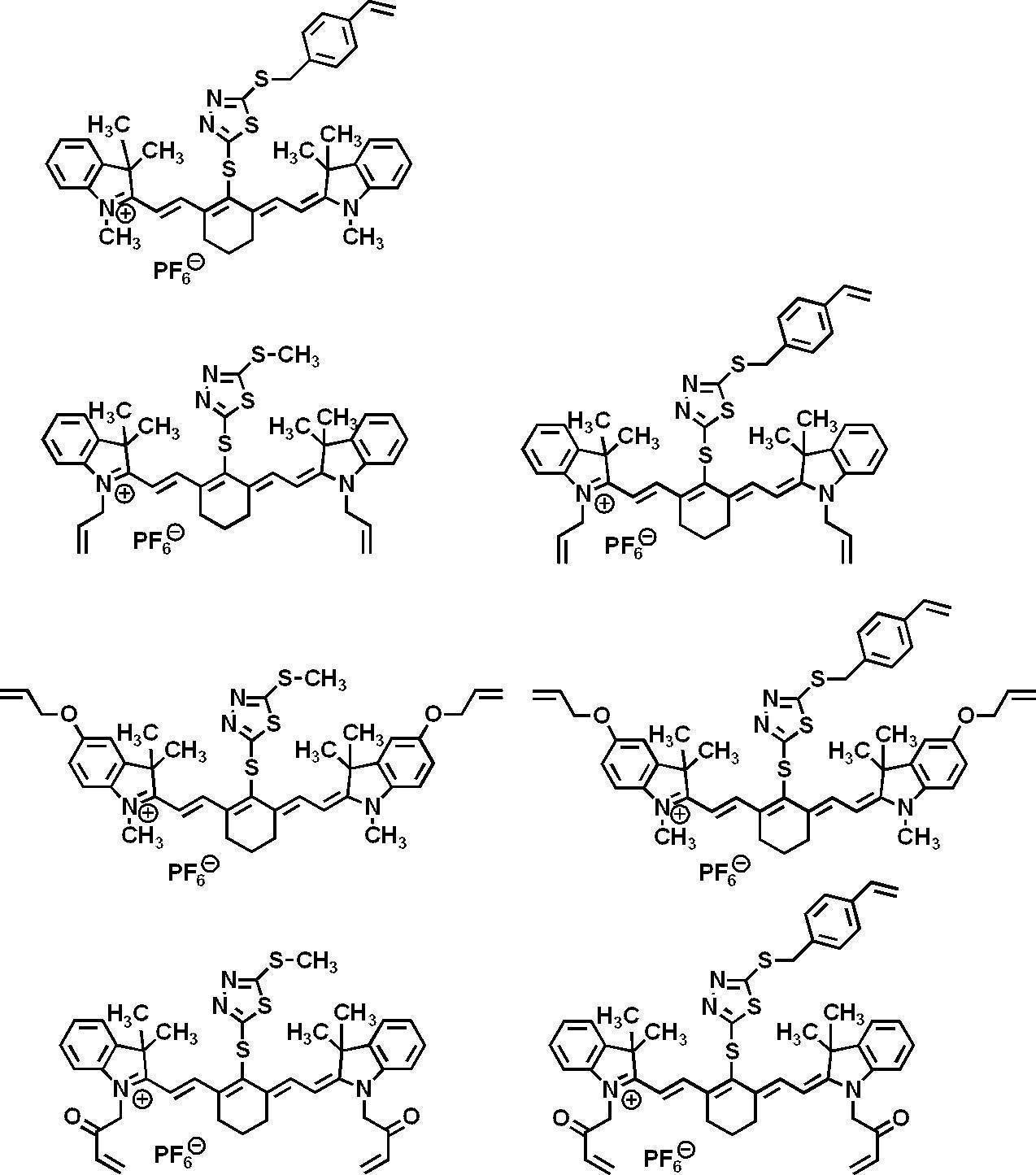

本開示に係る第一の輻射線感光性組成物において、分解型輻射線吸収化合物の含有量は、第一の輻射線感光性組成物の全固形分中、0.1~95質量%が好ましく、1~50質量%がより好ましく、1~20質量%が更に好ましい。 The decomposable radiation absorbing compounds may be used alone or in combination of two or more.
In the first radiation-sensitive composition according to the present disclosure, the content of the decomposable radiation absorbing compound is preferably 0.1 to 95% by mass in the total solid content of the first radiation-sensitive composition. 1 to 50% by mass is more preferable, and 1 to 20% by mass is more preferable.
本開示に係る第一の輻射線感光性組成物は、塗布性及び成膜性の観点から、バインダーポリマーを含有することが好ましい。ポリマーの種類は、公知のポリマーであれば特に限定されないが、皮膜形成用ポリマー、が好ましく挙げられる。皮膜形成用ポリマーとしては、(メタ)アクリル樹脂、ポリウレタン、ポリエステル、ポリアミド、ポリエーテル、ポリカーボネート、ポリウレア、ポリオレフィン、ビニル樹脂、ポリアミン等が挙げられる。第一の輻射線感光性組成物に用いるポリマーの形態は、組成物に溶解させて添加してもよい。組成物に溶解させて添加するポリマーとしては、(メタ)アクリル樹脂、ポリウレタン、ポリエステル、ビニル樹脂が好ましい。 [Binder polymer]
The first radiation-sensitive composition according to the present disclosure preferably contains a binder polymer from the viewpoint of coating properties and film forming properties. The type of polymer is not particularly limited as long as it is a known polymer, but film-forming polymers are preferably mentioned. Examples of the film-forming polymer include (meth) acrylic resins, polyurethanes, polyesters, polyamides, polyethers, polycarbonates, polyureas, polyolefins, vinyl resins, and polyamines. The form of the polymer used for the first radiation-sensitive composition may be dissolved in the composition and added. As the polymer to be dissolved and added to the composition, (meth) acrylic resin, polyurethane, polyester and vinyl resin are preferable.
上記バインダーポリマーとしては、アルキレンオキサイド鎖を有するポリマーが特に好ましい。アルキレンオキサイド鎖を有するポリマーは、ポリ(アルキレンオキサイド)部位を主鎖に有していても側鎖に有していてもよい。また、ポリ(アルキレンオキサイド)を側鎖に有するグラフトポリマーでも、ポリ(アルキレンオキサイド)含有繰返し単位で構成されるブロックと(アルキレンオキサイド)非含有繰返し単位で構成されるブロックとのブロックコポリマーでもよい。
ポリ(アルキレンオキサイド)部位を主鎖に有する場合は、ポリウレタンが好ましい。ポリ(アルキレンオキサイド)部位を側鎖に有する場合の主鎖のポリマーとしては、(メタ)アクリル樹脂、ポリビニルアセタール、ポリウレタン、ポリウレア、ポリイミド、ポリアミド、エポキシ樹脂、ポリスチレン、ノボラック型フェノール樹脂、ポリエステル、合成ゴム、及び、天然ゴムが挙げられ、(メタ)アクリル樹脂が特に好ましい。 When it is dissolved in a composition and added, as a binder polymer (also referred to as "binder polymer for on-press development") suitable for an on-press development type lithographic printing plate precursor, (meth) acrylic resin, polyurethane, polyester, vinyl Resin is preferable, and (meth) acrylic resin and polyurethane are more preferable.
As the above-mentioned binder polymer, a polymer having an alkylene oxide chain is particularly preferable. The polymer having an alkylene oxide chain may have a poly (alkylene oxide) moiety in its main chain or in its side chain. Further, it may be a graft polymer having a poly (alkylene oxide) in a side chain, or a block copolymer of a block constituted by a poly (alkylene oxide) -containing repeating unit and a block constituted by a (alkylene oxide) non-containing repeating unit.
When it has a poly (alkylene oxide) site in the main chain, polyurethane is preferred. (Meth) acrylic resin, polyvinyl acetal, polyurethane, polyurea, polyimide, polyamide, epoxy resin, polystyrene, novolac type phenol resin, polyester, synthetic, as a polymer of the main chain in the case of having a poly (alkylene oxide) site in a side chain Rubber and natural rubber are mentioned, and (meth) acrylic resin is particularly preferable.
ポリ(アルキレンオキサイド)部位におけるアルキレンオキサイドの繰返し数は、2~120が好ましく、2~70がより好ましく、2~50が更に好ましい。
アルキレンオキサイドの繰返し数が120以下であれば、皮膜強度の低下が抑制される。 As the alkylene oxide, an alkylene oxide having 2 to 6 carbon atoms is preferable, and ethylene oxide or propylene oxide is particularly preferable.
The repeating number of alkylene oxide in the poly (alkylene oxide) moiety is preferably 2 to 120, more preferably 2 to 70, and still more preferably 2 to 50.
If the number of repetitions of the alkylene oxide is 120 or less, the decrease in film strength is suppressed.

一価の有機基としては、炭素数1~6のアルキル基が好ましい。具体的には、メチル基、エチル基、n-プロピル基、イソプロピル基、n-ブチル基、sec-ブチル基、イソブチル基、tert-ブチル基、n-ペンチル基、イソペンチル基、ネオペンチル基、n-ヘキシル基、イソヘキシル基、1,1-ジメチルブチル基、2,2-ジメチルブチル基、シクロペンチル基及びシクロヘキシル基が挙げられる。
式(AO)において、yは2~70が好ましく、2~50がより好ましい。R1は水素原子又はメチル基が好ましく、水素原子が特に好ましい。R2は水素原子又はメチル基が特に好ましい。 In formula (AO), y represents 2 to 120, R 1 represents a hydrogen atom or an alkyl group, and R 2 represents a hydrogen atom or a monovalent organic group.
As the monovalent organic group, an alkyl group having 1 to 6 carbon atoms is preferable. Specifically, methyl group, ethyl group, n-propyl group, isopropyl group, n-butyl group, sec-butyl group, isobutyl group, tert-butyl group, n-pentyl group, isopentyl group, neopentyl group, n- And hexyl, isohexyl, 1,1-dimethylbutyl, 2,2-dimethylbutyl, cyclopentyl and cyclohexyl groups.
In the formula (AO), y is preferably 2 to 70, and more preferably 2 to 50. R 1 is preferably a hydrogen atom or a methyl group, particularly preferably a hydrogen atom. R 2 is particularly preferably a hydrogen atom or a methyl group.
主鎖にエチレン性不飽和結合を有するバインダーポリマーの例としては、ポリブタジエン、ポリイソプレンなどが挙げられる。
側鎖にエチレン性不飽和結合を有するバインダーポリマーの例としては、側鎖に(メタ)アクリレート基、(メタ)アクリルアミド基、ビニル基、又は、アリル基を有するポリマーが挙げられる。
ガラス転移温度を調整する方法としては、共重合するモノマーの組成やポリマーの分子量を変更し調整することができる。 The binder polymer is preferably crosslinkable in order to improve the film strength of the layer. In order to impart a crosslinkability to the binder polymer, a crosslinkable group such as an ethylenically unsaturated bond may be introduced to impart photocrosslinkability, or thermoplasticity may be imparted to impart heat crosslinkability. The crosslinkable group can be introduced at any position of the main chain or side chain of the polymer, and a method of introducing by copolymerization, and a method of introducing by polymer reaction after polymerization can be mentioned. In order to impart thermoplasticity, the glass transition temperature of the polymer may be adjusted.
Examples of binder polymers having an ethylenically unsaturated bond in the main chain include polybutadiene, polyisoprene and the like.
As an example of the binder polymer which has an ethylenically unsaturated bond in a side chain, the polymer which has a (meth) acrylate group, a (meth) acrylamide group, a vinyl group, or an allyl group in a side chain is mentioned.
As a method of adjusting the glass transition temperature, the composition of monomers to be copolymerized and the molecular weight of the polymer can be changed and adjusted.


また、本開示において、オリゴマーは、Mw800以上2,000未満のものとし、ポリマーは、Mw2,000以上のものとする。 The molecular weight of the binder polymer used in the present disclosure preferably has a weight average molecular weight (Mw) of 2,000 or more, preferably 5,000 or more, as a polystyrene conversion value by gel permeation chromatography (GPC) method Preferably, it is more preferably 10,000 to 300,000.
Also, in the present disclosure, the oligomer has a Mw of 800 or more and less than 2,000, and the polymer has a Mw of 2,000 or more.
バインダーポリマーは、第一の輻射線感光性組成物中に任意の量で含有させることができる。
バインダーポリマーの含有量は、第一の輻射線感光性組成物の用途などにより適宜選択できるが、第一の輻射線感光性組成物の全固形分に対して、1~90質量%が好ましく、5~80質量%がより好ましい。 In the first radiation-sensitive composition according to the present disclosure, one binder polymer may be used alone, or two or more binder polymers may be used in combination.
The binder polymer can be included in any amount in the first radiation-sensitive composition.
The content of the binder polymer can be appropriately selected depending on the application of the first radiation-sensitive composition and the like, but is preferably 1 to 90% by mass with respect to the total solid content of the first radiation-sensitive composition. 5 to 80% by mass is more preferable.
第一の輻射線感光性組成物の水溶性を向上させ、また、第一の輻射線感光性組成物を平版印刷版原版に用いた場合の機上現像性を向上させるために、第一の輻射線感光性組成物は、ミクロゲル及びポリマー粒子よりなる群から選ばれた少なくとも1つを含有してもよい。上記ミクロゲルやポリマー粒子は、赤外線照射による光や熱により架橋、溶融、又は、これら両方が生じる、或いは疎水性に変化することが好ましい。ミクロゲルやポリマー粒子は、非架橋性ミクロゲル、架橋性ミクロゲル、熱融着性粒子、熱反応性ポリマー粒子、及び、重合性基を有するポリマー粒子よりなる群から選ばれる少なくとも1つであることが好ましい。これらはコアシェル構造を有していてもよく、他の化合物を内包していてもよい。 [Microgel and polymer particles]
In order to improve the water solubility of the first radiation-sensitive composition and to improve the on-press developability when the first radiation-sensitive composition is used for a lithographic printing plate precursor, The radiation sensitive composition may contain at least one selected from the group consisting of microgels and polymer particles. The microgel and the polymer particles are preferably crosslinked, melted, or both generated or changed to hydrophobicity by light or heat due to infrared irradiation. The microgel and the polymer particles are preferably at least one selected from the group consisting of non-crosslinkable microgels, crosslinkable microgels, thermally fusible particles, thermally reactive polymer particles, and polymer particles having a polymerizable group. . These may have a core-shell structure, and may contain other compounds.
熱融着性粒子を構成するポリマーの具体例としては、エチレン、スチレン、塩化ビニル、アクリル酸メチル、アクリル酸エチル、メタクリル酸メチル、メタクリル酸エチル、塩化ビニリデン、アクリロニトリル、ビニルカルバゾール、ポリアルキレン構造を有するアクリレート又はメタクリレートなどのモノマーのホモポリマー若しくはコポリマー又はそれらの混合物が挙げられる。好ましくは、ポリスチレン、スチレン及びアクリロニトリルを含む共重合体、並びに、ポリメタクリル酸メチルが挙げられる。 As heat fusion particles, for example, Research Disclosure No. 1 in January 1992. Polymer particles described in 33303, JP-A-9-123387, JP-A-9-131850, JP-A-9-171249, JP-A-9-171250, European Patent 931647, and the like are preferably mentioned.
Specific examples of the polymer constituting the heat fusible particle include ethylene, styrene, vinyl chloride, methyl acrylate, ethyl acrylate, methyl methacrylate, ethyl methacrylate, vinylidene chloride, acrylonitrile, vinyl carbazole, polyalkylene structure And homopolymers or copolymers of monomers such as acrylates or methacrylates, or mixtures thereof. Preferably, polystyrene, copolymers containing styrene and acrylonitrile, and poly (methyl methacrylate) can be mentioned.
本開示に係る第一の輻射線感光性組成物中に、ポリマーを、マイクロカプセル、ミクロゲル又はポリマー粒子の形態で含む場合、マイクロカプセル、ミクロゲル又はポリマー粒子の平均一次粒子径は、10~1,000nmであることが好ましく、20~300nmであることがより好ましく、30~120nmであることが更に好ましい。
平均一次粒子径は光散乱法により測定することができる。
ミクロゲルやポリマー粒子の含有量は、第一の輻射線感光性組成物の全固形分に対して、5~90質量%が好ましい。 Known methods can be used to microencapsulate or microgelate the components of the first radiation-sensitive composition.
When the polymer is contained in the form of microcapsules, microgels or polymer particles in the first radiation-sensitive composition according to the present disclosure, the average primary particle size of the microcapsules, microgels or polymer particles is 10 to 1,1. The thickness is preferably 000 nm, more preferably 20 to 300 nm, and still more preferably 30 to 120 nm.
The average primary particle size can be measured by light scattering.
The content of the microgel and the polymer particles is preferably 5 to 90% by mass with respect to the total solid content of the first radiation-sensitive composition.
本開示に係る第一の輻射線感光性組成物は、赤外線吸収剤を含有することができる。赤外線吸収剤を含有することにより、本開示に係る第一の輻射線感光性組成物は、赤外線感光性組成物としてより好適に用いることができる。
本開示に係る第一の輻射線感光性組成物において、赤外線吸収剤には、上述の輻射線吸収化合物に該当する分解型輻射線吸収化合物は含まないものとする。
赤外線吸収剤は、吸収した赤外線を熱に変換する機能を有する化合物である。また、赤外線吸収剤は、赤外線により励起してラジカル開始剤等に電子移動やエネルギー移動する機能を有していてもよい。
赤外線吸収剤は、750~1,400nmの波長域に極大吸収を有することが好ましい。赤外線吸収剤としては、染料又は顔料が好ましく用いられる。 [Infrared absorber]
The first radiation-sensitive composition according to the present disclosure can contain an infrared absorber. By containing an infrared absorber, the first radiation-sensitive composition according to the present disclosure can be more suitably used as an infrared-sensitive composition.
In the first radiation-sensitive composition according to the present disclosure, the infrared ray absorbing agent does not include the decomposable radiation absorbing compound corresponding to the above-mentioned radiation absorbing compound.
The infrared absorber is a compound having a function of converting the absorbed infrared radiation into heat. In addition, the infrared absorber may have a function of being excited by infrared rays to cause electron transfer or energy transfer to a radical initiator or the like.
The infrared absorber preferably has maximum absorption in the wavelength range of 750 to 1,400 nm. As the infrared absorber, a dye or a pigment is preferably used.
これらの染料のうち好ましいものとしては、シアニン色素、スクアリリウム色素、及び、ピリリウム塩が挙げられる。中でも、シアニン色素が好ましく、インドレニンシアニン色素が特に好ましい。 As dyes, commercially available dyes and, for example, known dyes described in documents such as "Dye Handbook" (edited by the Society of Synthetic Organic Chemistry, published in 1945) can be used. Specifically, dyes such as azo dyes, metal complex salt azo dyes, pyrazolone azo dyes, naphthoquinone dyes, anthraquinone dyes, phthalocyanine dyes, carbonium dyes, quinoneimine dyes, methine dyes, cyanine dyes, squarylium dyes, pyrylium salts, metal thiolate complexes, etc. Can be mentioned.
Among these dyes, preferred are cyanine dyes, squarylium dyes and pyrylium salts. Among them, cyanine dyes are preferable, and indolenine cyanine dyes are particularly preferable.
また、特開平5-5005号公報の段落0008~0009、特開2001-222101号公報の段落0022~0025に記載の化合物も好ましく使用することができる。
顔料としては、特開2008-195018号公報の段落0072~0076に記載の化合物が好ましい。 Specific examples of the cyanine dye include compounds described in paragraphs 0017 to 0019 of JP-A 2001-133969, paragraphs 0016 to 0021 of JP-A 2002-023360, and paragraphs 0012 to 0037 of JP-A 2002-040638. Compounds described in JP-A-2002-278057, preferably compounds described in paragraphs 0034-0041 of JP-A-2002-195018, and particularly preferably compounds described in JP-A-2007-90850 The compounds described in 0043 can be mentioned.
Further, compounds described in paragraphs 0008 to 0009 of JP-A-5-5005 and paragraphs 0022 to 0025 of JP-A 2001-222101 can also be preferably used.
As the pigment, the compounds described in paragraphs 0072 to 0076 of JP-A-2008-195018 are preferable.
赤外線吸収剤は、第一の輻射線感光性組成物中に任意な量で含有させることができる。赤外線吸収剤の含有量は、第一の輻射線感光性組成物の全固形分100質量部に対し、0.05~30質量%であることが好ましく、0.1~20質量%であることがより好ましく、0.2~10質量%であることが更に好ましい。 The infrared absorber may be used alone or in combination of two or more. Moreover, you may use together a pigment and dye as an infrared rays absorber.
The infrared absorber can be contained in any amount in the first radiation-sensitive composition. The content of the infrared absorber is preferably 0.05 to 30% by mass, and more preferably 0.1 to 20% by mass, with respect to 100 parts by mass of the total solid content of the first radiation-sensitive composition. Is more preferable, and 0.2 to 10% by mass is more preferable.
本開示に係る第一の輻射線感光性組成物は、必要に応じて、上記以外の添加剤(例えば、界面活性剤)を含有することができる。 [Other ingredients]
The first radiation-sensitive composition according to the present disclosure can optionally contain other additives (for example, surfactants).
本開示に係る第一の輻射線感光性組成物に含有される各成分は、適当な溶剤に溶解又は分散して塗布液を調製し、塗布液を支持体等に塗布、乾燥して、組成物膜を形成することができる。
溶剤としては、公知の溶剤を用いることができる。具体的には例えば、水、アセトン、メチルエチルケトン(2-ブタノン)、シクロヘキサン、酢酸エチル、エチレンジクロライド、テトラヒドロフラン、トルエン、エチレングリコールモノメチルエーテル、エチレングリコールモノエチルエーテル、エチレングリコールジメチルエーテル、プロピレングリコールモノメチルエーテル、プロピレングリコールモノエチルエーテル、アセチルアセトン、シクロヘキサノン、ジアセトンアルコール、エチレングリコールモノメーチルエーテルアセテート、エチレングリコールエチルエーテルアセテート、エチレングリコールモノイソプロピルエーテル、エチレングリコールモノブチルエーテルアセテート、1-メトキシ-2-プロパノール、3-メトキシ-1-プロパノール、メトキシメトキシエタノール、ジエチレングリコールモノメチルエーテル、ジエチレングリコールモノエチルエーテル、ジエチレングリコールジメチルエーテル、ジエチレングリコールジエチルエーテル、プロピレングリコールモノメチルエーテルアセテート、プロピレングリコールモノエチルエーテルアセテート、3-メトキシプロピルアセテート、N,N-ジメチルホルムアミド、ジメチルスルホキシド、γ-ブチロラクトン、乳酸メチル、乳酸エチル等が挙げられる。溶剤は、1種単独、又は、2種以上を混合して使用することができる。塗布液中の固形分濃度は1~50質量%程度であることが好ましい。 [Formation of composition film]
Each component contained in the first radiation-sensitive composition according to the present disclosure is dissolved or dispersed in a suitable solvent to prepare a coating solution, and the coating solution is applied to a support or the like and dried to form a composition. An object film can be formed.
A well-known solvent can be used as a solvent. Specifically, for example, water, acetone, methyl ethyl ketone (2-butanone), cyclohexane, ethyl acetate, ethylene dichloride, tetrahydrofuran, toluene, ethylene glycol monomethyl ether, ethylene glycol monoethyl ether, ethylene glycol dimethyl ether, propylene glycol monomethyl ether, propylene Glycol monoethyl ether, acetylacetone, cyclohexanone, diacetone alcohol, ethylene glycol monomethyl ether acetate, ethylene glycol ethyl ether acetate, ethylene glycol monoisopropyl ether, ethylene glycol monobutyl ether acetate, 1-methoxy-2-propanol, 3-methoxy -1-propanol, methoxymethoxye Nole, diethylene glycol monomethyl ether, diethylene glycol monoethyl ether, diethylene glycol dimethyl ether, diethylene glycol diethyl ether, propylene glycol monomethyl ether acetate, propylene glycol monoethyl ether acetate, 3-methoxypropyl acetate, N, N-dimethylformamide, dimethyl sulfoxide, γ-butyrolactone And methyl lactate, ethyl lactate and the like. A solvent can be used individually by 1 type or in mixture of 2 or more types. The solid concentration in the coating solution is preferably about 1 to 50% by mass.
本開示に係る第二の輻射線感光性組成物は、ラジカル開始剤と、ラジカル重合性成分と、輻射線吸収化合物と、を含み、上記ラジカル開始剤が、電子供与型ラジカル開始剤、及び、電子受容型ラジカル開始剤を含み、画像形成輻射線の暴露後のラジカル発生量対時間曲線に2以上のラジカル発生量のピークを有する。
第二の輻射線感光性組成物は、例えば、下記反応式に示す反応により、第一のラジカル及び第二のラジカルを発生する。
その結果、第二の輻射線感光性組成物は、画像形成輻射線の暴露後のラジカル発生量対時間曲線に2以上のラジカル発生量のピークを有する。 <Second radiation-sensitive composition>
A second radiation-sensitive composition according to the present disclosure includes a radical initiator, a radically polymerizable component, and a radiation absorbing compound, and the radical initiator is an electron donating radical initiator, and An electron accepting radical initiator is included, and has a peak of two or more radical generation amounts in a radical generation amount vs. time curve after exposure to imaging radiation.
The second radiation-sensitive composition generates, for example, a first radical and a second radical by the reaction shown in the following reaction formula.
As a result, the second radiation-sensitive composition has a peak of two or more radical generations in a radical generation versus time curve after exposure of the imaging radiation.

また、電子供与型ラジカル開始剤から輻射線吸収化合物への電子移動が起こり、第二のラジカルが発生すると推測される。
上記第一のラジカルが発生する反応と、第二のラジカルが発生する反応の間に反応速度差があることにより、本開示に係る第二の輻射線感光性組成物においては、画像形成輻射線の暴露後のラジカル発生量対時間曲線に2以上のラジカル発生量のピークを有する。
また、輻射線吸収化合物の最高被占軌道(HOMO)と、電子供与型ラジカル開始剤のHOMOの差が大きいほど、第二以降のピークの発生が遅くなり、第二のラジカル発生量は減少すると推測される。
上記反応式中、Phはフェニル基を表す。 In the above reaction formula, it is presumed that irradiation of the image forming radiation excites the radiation absorbing compound to cause electron transfer to the electron accepting radical initiator to generate the first radical.
It is also presumed that electron transfer from the electron donating radical initiator to the radiation absorbing compound occurs to generate a second radical.
In the second radiation-sensitive composition according to the present disclosure, there is a difference in reaction rate between the reaction in which the first radical is generated and the reaction in which the second radical is generated. Has a peak of 2 or more of the radical generation amount in the radical generation amount versus time curve after the exposure.
In addition, as the difference between the highest occupied molecular orbital (HOMO) of the radiation absorbing compound and the HOMO of the electron donor radical initiator is larger, the generation of the second and subsequent peaks is delayed, and the second radical generation amount is decreased. It is guessed.
In the above reaction formula, Ph represents a phenyl group.
本開示に係る第二の輻射線感光性組成物におけるラジカル開始剤は、電子供与型ラジカル開始剤、及び、電子受容型ラジカル開始剤を含む。
ここで、第二の輻射線感光性組成物における電子供与型ラジカル開始剤は、上述の第一の輻射線感光性組成物における電子受容型ラジカル開始剤と同義であり、好ましい態様も同様である。 [Radical initiator]
The radical initiator in the second radiation-sensitive composition according to the present disclosure includes an electron donating radical initiator and an electron accepting radical initiator.
Here, the electron-donating radical initiator in the second radiation-sensitive composition has the same meaning as the electron-accepting radical initiator in the above-mentioned first radiation-sensitive composition, and the preferred embodiments are also the same. .
電子受容型ラジカル開始剤としては、例えば、(a)有機ハロゲン化物、(b)カルボニル化合物、(c)アゾ化合物、(d)有機過酸化物、(e)メタロセン化合物、(f)アジド化合物、(g)ヘキサアリールビイミダゾール化合物、(h)ジスルホン化合物、(i)オキシムエステル化合物、及び、(j)オニウム塩化合物が挙げられる。 -Electron Acceptable Radical Initiator-
Examples of electron accepting radical initiators include (a) organic halides, (b) carbonyl compounds, (c) azo compounds, (d) organic peroxides, (e) metallocene compounds, (f) azide compounds, (G) Hexaaryl biimidazole compounds, (h) disulfone compounds, (i) oxime ester compounds, and (j) onium salt compounds.
(b)カルボニル化合物としては、例えば、特開2008-195018号公報の段落0024に記載の化合物が好ましい。
(c)アゾ化合物としては、例えば、特開平8-108621号公報に記載のアゾ化合物等が挙げられる。
(d)有機過酸化物としては、例えば、特開2008-195018号公報の段落0025に記載の化合物が好ましい。
(e)メタロセン化合物としては、例えば、特開2008-195018号公報の段落0026に記載の化合物が好ましい。
(f)アジド化合物としては、例えば、2,6-ビス(4-アジドベンジリデン)-4-メチルシクロヘキサノン等の化合物が挙げられる。
(g)ヘキサアリールビイミダゾール化合物としては、例えば、特開2008-195018号公報の段落0027に記載の化合物が好ましい。
(h)ジスルホン化合物としては、例えば、特開昭61-166544号、特開2002-328465号の各公報に記載の化合物が挙げられる。
(i)オキシムエステル化合物としては、例えば、特開2008-195018号公報の段落0028~0030に記載の化合物が好ましい。 As the organic halide (a), for example, compounds described in paragraphs 0022 to 0023 of JP-A-2008-195018 are preferable.
(B) As a carbonyl compound, the compound as described in stage 0024 of Unexamined-Japanese-Patent No. 2008-195018 is preferable, for example.
Examples of the azo compound (c) include the azo compounds described in JP-A-8-108621.
As the organic peroxide (d), for example, a compound described in paragraph 0025 of JP-A-2008-195018 is preferable.
(E) As a metallocene compound, the compound as described in Paragraph 0026 of Unexamined-Japanese-Patent No. 2008-195018 is preferable, for example.
Examples of the azide compound (f) include compounds such as 2,6-bis (4-azidobenzylidene) -4-methylcyclohexanone.
(G) As a hexaaryl biimidazole compound, the compound as described in stage 0027 of Unexamined-Japanese-Patent No. 2008-195018 is preferable, for example.
Examples of the (h) disulfone compound include compounds described in JP-A-61-166544 and JP-A-2002-328465.
As the oxime ester compound (i), for example, compounds described in paragraphs 0028 to 0030 of JP-A-2008-195018 are preferable.
電子受容型ラジカル開始剤の含有量は、第二の輻射線感光性組成物の全固形分に対して、0.1~50質量%が好ましく、0.5~30質量%がより好ましく、0.8~20質量%が特に好ましい。 The electron accepting radical initiator may be used alone or in combination of two or more.
The content of the electron accepting radical initiator is preferably 0.1 to 50% by mass, more preferably 0.5 to 30% by mass, relative to the total solid content of the second radiation-sensitive composition. 8 to 20% by weight is particularly preferred.
第二の輻射線感光性組成物におけるラジカル重合性成分は、第一の輻射線感光性組成物におけるラジカル重合性成分と同義であり、好ましい態様も同様である。 [Radical polymerizable component]
The radically polymerizable component in the second radiation-sensitive composition has the same meaning as the radically polymerizable component in the first radiation-sensitive composition, and preferred embodiments are also the same.
第二の輻射線感光性組成物における輻射線吸収化合物としては、第一の輻射線感光性組成物における輻射線吸収化合物を用いてもよいし、第一の輻射線感光性組成物における赤外線吸収剤を用いてもよい。これらの化合物の好ましい態様は、第一の輻射線感光性組成物におけるこれらの化合物の好ましい態様と同様である。 [Radiation absorbing compound]
As the radiation absorbing compound in the second radiation-sensitive composition, the radiation absorbing compound in the first radiation-sensitive composition may be used, or the infrared absorption in the first radiation-sensitive composition An agent may be used. Preferred embodiments of these compounds are the same as preferred embodiments of these compounds in the first radiation-sensitive composition.
耐刷性及び調子再現性の観点から、第二の輻射線感光性組成物における上記輻射線吸収化合物の最高被占軌道(HOMO)と上記電子供与型ラジカル開始剤のHOMOとの差(電位差ΔG2、ΔG2=輻射線吸収化合物のHOMO-電子供与型ラジカル開始剤のHOMO)は、0.50eV以上が好ましく、0.60eV~1.50eVがより好ましく、0.61eV~1.30eVが更に好ましく、0.65eV~1.20eVが特に好ましい。
第二の輻射線吸収化合物が、輻射線吸収化合物、及び、電子供与型ラジカル開始剤の両方又は一方を複数種含有する場合、輻射線吸収化合物のHOMOと電子供与型ラジカル開始剤のHOMOの差が上記範囲内となる輻射線吸収化合物と電子供与型ラジカル開始剤との組み合わせが存在することが好ましい。 -Highest occupied orbit (HOMO) and lowest unoccupied orbit (LUMO)-
From the viewpoint of printing durability and tone reproducibility, the difference between the highest occupied molecular orbital (HOMO) of the radiation absorbing compound and the HOMO of the electron donor radical initiator in the second radiation-sensitive composition (potential difference ΔG 2 0.52 eV or more is preferable, 0.60 eV to 1.50 eV is more preferable, and 0.61 eV to 1.30 eV is more preferable, where ΔG 2 = HOMO of electron absorbing radical of radiation absorbing compound is preferably 0.50 eV or more. Particularly preferred is 0.65 eV to 1.20 eV.
When the second radiation absorbing compound contains both or one of the radiation absorbing compound and the electron donating radical initiator, the difference between the HOMO of the radiation absorbing compound and the HOMO of the electron donating radical initiator It is preferred that there be a combination of a radiation absorbing compound and an electron donating radical initiator such that is within the above range.
第二の輻射線吸収化合物が、輻射線吸収化合物、及び、電子受容型ラジカル開始剤の両方又は一方を複数種含有する場合、輻射線吸収化合物のLUMOと電子受容型ラジカル開始剤のLUMOの差が上記範囲内となる輻射線吸収化合物と電子受容型ラジカル開始剤との組み合わせが存在することが好ましい。 Also, from the viewpoint of printing durability and tone reproducibility, the difference between the lowest unoccupied orbital (LUMO) of the electron accepting radical initiator and the LUMO of the radiation absorbing compound in the second radiation-sensitive composition (potential difference [Delta] G3, [Delta] G3 = LUMO of electron accepting radical initiator-LUMO of the radiation absorbing compound is preferably 0.90 eV or less, preferably 0.85 eV or less, and more preferably 0.80 eV or less, Further, 0.75 eV or less is more preferable. The lower limit is not particularly limited, but is preferably 0.10 eV or more.
When the second radiation absorbing compound contains both or one of the radiation absorbing compound and the electron accepting radical initiator, the difference between the LUMO of the radiation absorbing compound and the LUMO of the electron accepting radical initiator It is preferred that there be a combination of a radiation absorbing compound and an electron accepting radical initiator such that is within the above range.
まず、計算対象となる化合物における対アニオンは無視する。
量子化学計算ソフトウェアGaussian09を用い、構造最適化はDFT(B3LYP/6-31G(d))で行う。
MO(分子軌道)エネルギー計算は、上記構造最適化で得た構造でDFT(B3LYP/6-31+G(d,p)/CPCM(solvent=methanol))で行う。
上記MOエネルギー計算で得られたMOエネルギーEbare(単位:hartree)を以下の公式により、本開示においてHOMO及びLUMOの値として用いるEscaled(単位:eV)へ変換する。
Escaled=0.823168×27.2114×Ebare-1.07634
なお、27.2114は単にhartreeをeVに変換するための係数であり、0.823168と-1.07634とは調節係数であり、計算対象となる化合物のHOMOとLUMOとを計算が実測の値に合うように定めた。
輻射線吸収化合物のHOMOと電子供与型ラジカル開始剤のHOMOとの差分からΔG2を求める(ΔG2=輻射線吸収化合物のHOMO-電子供与型ラジカル開始剤のHOMO)。
また、電子受容型ラジカル開始剤のLUMOと輻射線吸収化合物のLUMOとの差分からΔG3を求める(ΔG3=電子受容型ラジカル開始剤のLUMO-輻射線吸収化合物のLUMO)。 In the present disclosure, calculation of HOMO and LUMO is performed by the following method.
First, the counter anion in the compound to be calculated is ignored.
Structural optimization is performed by DFT (B3LYP / 6-31G (d)) using quantum chemistry calculation software Gaussian09.
MO (molecular orbital) energy calculation is performed by DFT (B3LYP / 6-31 + G (d, p) / CPCM (solvent = methanol)) with the structure obtained by the above-mentioned structure optimization.
The MO energy E bare (unit: hartree) obtained by the above MO energy calculation is converted to E scaled (unit: eV) used as the HOMO and LUMO values in the present disclosure according to the following formula.
Escaled = 0.823168 × 27.2114 × Ebare-1.07634
Note that 27.2114 is simply a coefficient to convert hartree to eV, and 0.823168 and -1.07634 are adjustment coefficients, and the HOMO and LUMO of the compound to be calculated are calculated by actual calculation. I decided to fit.
ΔG 2 is determined from the difference between the HOMO of the radiation absorbing compound and the HOMO of the electron donating radical initiator (ΔG 2 = HOMO of the radiation absorbing compound—HOMO of the electron donating radical initiator).
In addition, ΔG 3 is determined from the difference between LUMO of the electron accepting radical initiator and LUMO of the radiation absorbing compound (ΔG 3 = LUMO of electron accepting radical initiator—LUMO of the radiation absorbing compound).
また、上記電子受容型ラジカル開始剤のLUMOと上記輻射線吸収化合物のLUMOとの電位差が上記範囲内である場合、輻射線吸収化合物からの電子受容型ラジカル開始剤への電子の受け渡しが促進され、ラジカル重合性成分の重合が促進され、組成物の硬化性に優れると考えられる。 When the potential difference between the HOMO of the radiation absorbing compound and the HOMO of the electron donating radical initiator is within the above range, the stability of the electron donating radical initiator other than at the time of image forming radiation exposure is excellent and the image is During formation radiation exposure, electron transfer from HOMO of the electron donating radical initiator to HOMO of the radiation absorbing compound occurs, thereby promoting excitation of the radiation absorbing compound to the lowest unoccupied orbital (LUMO), It is believed to accelerate the decomposition of the radiation absorbing compound.
When the potential difference between the LUMO of the electron accepting radical initiator and the LUMO of the radiation absorbing compound is within the above range, transfer of electrons from the radiation absorbing compound to the electron accepting radical initiator is promoted. It is considered that the polymerization of the radically polymerizable component is promoted and the curability of the composition is excellent.
第二の輻射線感光性組成物は、バインダーポリマーを含むことが好ましい。
第二の輻射線感光性組成物におけるバインダーポリマーは、第一の輻射線感光性組成物におけるバインダーポリマーと同義であり、好ましい態様も同様である。 [Binder polymer]
The second radiation-sensitive composition preferably comprises a binder polymer.
The binder polymer in the second radiation-sensitive composition has the same meaning as the binder polymer in the first radiation-sensitive composition, and preferred embodiments are also the same.
第二の輻射線感光性組成物は、ミクロゲル及びポリマー粒子を含むことが好ましい。
第二の輻射線感光性組成物におけるミクロゲル及びポリマー粒子は、第一の輻射線感光性組成物におけるミクロゲル及びポリマー粒子と同義であり、好ましい態様も同様である。 [Microgel and polymer particles]
The second radiation-sensitive composition preferably comprises microgels and polymer particles.
The microgel and polymer particles in the second radiation-sensitive composition are the same as the microgel and polymer particles in the first radiation-sensitive composition, and preferred embodiments are also the same.
本開示に係る第二の輻射線感光性組成物は、必要に応じて、上記以外の添加剤(例えば、界面活性剤)を含有することができる。 [Other ingredients]
The second radiation-sensitive composition according to the present disclosure can optionally contain other additives (for example, surfactants).
本開示に係る第二の輻射線感光性組成物に含有される各成分は、適当な溶剤に溶解又は分散して塗布液を調製し、塗布液を支持体等に塗布、乾燥して、組成物膜を形成することができる。
上記調製において用いられる溶剤及び塗布液中の固形分濃度としては、上述の第一の輻射線感光性組成物を用いて塗布液を調製する場合の溶剤及び塗布液中の固形分濃度を用いることができる。 [Formation of composition film]
Each component contained in the second radiation-sensitive composition according to the present disclosure is dissolved or dispersed in a suitable solvent to prepare a coating solution, and the coating solution is applied to a support or the like and dried to form a composition. An object film can be formed.
As solid content concentration in the solvent and coating liquid used in the above-mentioned preparation, solid content concentration in the solvent and coating liquid in the case of preparing a coating liquid using the above-mentioned first radiation sensitive composition is used Can.
本開示に係る輻射線感光性組成物は、画像形成材料に好ましく用いられる。画像形成材料としては、平版印刷版原版、プリント配線基板、カラーフィルター、フォトマスクなどの画像露光による重合硬化を利用する画像形成材料が挙げられる。
本開示に係る第一の輻射線感光性組成物を使用した画像形成材料は、画像形成輻射線を放射する光源で露光されることにより硬化した領域を形成する。画像形成輻射線を放射する光源としては、赤外線を放射する固体レーザー及び半導体レーザー等が挙げられる。 <Application of radiation-sensitive composition>
The radiation-sensitive composition according to the present disclosure is preferably used in an image forming material. Examples of the image forming material include an image forming material utilizing polymerization and curing by image exposure such as a lithographic printing plate precursor, a printed wiring board, a color filter, and a photomask.
An imaging material using a first radiation-sensitive composition according to the present disclosure forms a cured area upon exposure to a light source emitting imaging radiation. Light sources that emit imaging radiation include solid-state lasers and semiconductor lasers that emit infrared light.
本開示に係る平版印刷版原版は、支持体と、ラジカル開始剤、ラジカル重合性成分、及び輻射線吸収化合物を含み、画像形成輻射線の暴露後のラジカル発生量対時間曲線に2以上のラジカル発生量のピークを有する画像記録層と、を有する。
また、本開示に係る平版印刷版原版は、赤外線による露光を可能とする観点から、含まれる輻射線吸収化合物が赤外線吸収化合物であることが好ましい。 (Lithographic printing plate precursor)
A lithographic printing plate precursor according to the present disclosure comprises a support, a radical initiator, a radically polymerizable component, and a radiation absorbing compound, and has two or more radicals in a radical generation amount vs. time curve after exposure to imaging radiation. And an image recording layer having a peak of generation amount.
Further, in the planographic printing plate precursor according to the present disclosure, the radiation absorbing compound contained is preferably an infrared absorbing compound from the viewpoint of enabling exposure by infrared light.
画像記録層が、画像形成輻射線の暴露後のラジカル発生量対時間曲線に2以上のラジカル発生量のピークを有することは、ナノ過渡吸収による測定により確認される。
具体的には、石英基板上に、平版印刷版原版の画像記録層を溶解した溶液を塗布、乾燥して、上記画像記録層の乾燥塗布量と同等の量になるように塗布膜を形成する。形成された塗布膜に、画像形成輻射線として用いられる波長のナノ秒レーザーパルスを照射する。それと同期してモニター用レーザー光(観測するラジカルが吸収を持つ波長)を発振させ、モニター用レーザー光の光子数の時間変化を光電子増倍管(PMT)により検出して、オシロスコープで計測する手法により測定される。
平版印刷版原版の画像記録層を溶解した溶液は、画像記録層を溶剤により溶解することにより得ることができる。
溶剤としては、画像記録層を溶解する溶剤であればよく、例えば、上述の組成物膜の形成において用いられる溶剤が挙げられる。
ただし、平版印刷版原版が保護層を有する場合など、画像記録層の溶解が困難である場合には、平版印刷版原版の画像記録層の形成に用いた組成物を、上述の平版印刷版原版の画像記録層を溶解した溶液の替わりに用いて上記測定を行う。
上記測定方法により、ラジカル発生量対時間曲線に2以上のラジカル発生量のピークが存在する場合に、画像形成輻射線の暴露後のラジカル発生量対時間曲線に2以上のラジカル発生量のピークを有する画像記録層を平版印刷版原版が有するとみなす。
その他、ナノ過渡吸収による測定方法の好ましい態様は、上述の輻射線感光性組成物におけるナノ過渡吸収による測定におけるナノ過渡吸収による測定方法の好ましい態様と同様である。 <Peak of radical generation amount>
It is confirmed by measurement by nanotransient absorption that the image recording layer has a peak of two or more radical generation amounts in a radical generation amount vs. time curve after exposure of the imaging radiation.
Specifically, a solution in which the image recording layer of a lithographic printing plate precursor is dissolved is applied onto a quartz substrate and dried to form a coating film in an amount equivalent to the dry coating amount of the image recording layer. . The coating film formed is irradiated with a nanosecond laser pulse of a wavelength used as imaging radiation. A method that oscillates the monitor laser light (the wavelength at which the observed radical absorbs) in synchronization with it, detects the time change of the number of photons of the monitor laser light with a photomultiplier tube (PMT), and measures with an oscilloscope Measured by
The solution in which the image recording layer of the lithographic printing plate precursor is dissolved can be obtained by dissolving the image recording layer with a solvent.
The solvent may be any solvent that dissolves the image recording layer, and examples thereof include the solvents used in the formation of the composition film described above.
However, in the case where dissolution of the image recording layer is difficult, such as when the lithographic printing plate precursor has a protective layer, the above-described lithographic printing plate precursor may be a composition used to form the image recording layer of the lithographic printing plate precursor. The above measurement is performed using a solution obtained by dissolving the image recording layer of
By the above measurement method, when there are two or more peaks of radical generation in the radical generation vs. time curve, two or more peaks of radical generation in the radical generation vs. time curve after exposure of the imaging radiation It is considered that the lithographic printing plate precursor has an image recording layer.
In addition, the preferable aspect of the measuring method by nano transient absorption is the same as the preferable aspect of the measuring method by nano transient absorption in the measurement by nano transient absorption in the above-mentioned radiation-sensitive composition.
上述の方法により、平版印刷版原版の画像記録層を溶解した溶液を用いて測定したピーク間隔は、平版印刷版の画像記録層におけるピーク間隔と同様であるとみなすことができる。 The image recording layer according to the present disclosure has, from the viewpoint of improvement of printing durability, a peak of the radical generation amount initially generated with respect to time after exposure of the image forming radiation, which is included in the peak of the radical generation amount; The peak interval of at least one of the peaks of the amount of radical generation occurring on the second and subsequent ones is preferably 30 ms or more, more preferably 40 ms or more, more preferably 40 ms to 500 ms, and 50 ms It is further preferable that it is ~ 300 ms.
The peak interval measured using the solution in which the image recording layer of the lithographic printing plate precursor is dissolved by the method described above can be considered to be similar to the peak interval in the image recording layer of the lithographic printing plate.
例えば、画像記録層が、上記分解型輻射線吸収化合物を含むことにより、時間に対して2番目以降に発生するラジカル発生量のピークの少なくとも1つが、上記輻射線吸収化合物の分解物に由来するピークとなる。 In addition, in the image recording layer according to the present disclosure, from the viewpoint of coexistence of printing durability and tone reproducibility, among the peaks of the radical generation amount, it occurs second or later with respect to time after exposure to image forming radiation. It is preferable that at least one of the peaks of the radical generation amount is a peak derived from the decomposition product of the radiation absorbing compound.
For example, when the image recording layer contains the above-described decomposed radiation absorbing compound, at least one of the peaks of the amount of radical generation occurring second or later with respect to time is derived from the decomposed product of the above radiation absorbing compound It becomes a peak.
本開示に係る平版印刷版原版の第一の態様(以下、「第一の平版印刷版原版」ともいう)は、
支持体と、ラジカル開始剤、ラジカル重合性成分、及び、輻射線吸収化合物を含み、画像形成輻射線の暴露後のラジカル発生量対時間曲線に2以上のラジカル発生量のピークを有する画像記録層と、を有し、
上記ラジカル開始剤が、電子供与型ラジカル開始剤を含み、かつ、上記輻射線吸収化合物が、画像形成輻射線の暴露により分解してラジカルを発生する化合物を含む、
平版印刷版原版である。
第一の平版印刷版原版における画像記録層は、例えば、第一の輻射線感光性組成物に、必要に応じて溶剤等のその他の成分を加えた塗布液を塗布することにより形成される。 <Aspect of planographic printing plate precursor>
The first aspect of the lithographic printing plate precursor according to the present disclosure (hereinafter also referred to as “first lithographic printing plate precursor”) is
Image recording layer comprising a support, a radical initiator, a radically polymerizable component, and a radiation absorbing compound and having a peak of two or more radical generation amounts in a radical generation amount vs. time curve after exposure to imaging radiation And
The radical initiator comprises an electron donating radical initiator and the radiation absorbing compound comprises a compound which decomposes upon exposure to imaging radiation to generate a radical
It is a lithographic printing plate precursor.
The image recording layer in the first lithographic printing plate precursor is formed, for example, by applying a coating solution obtained by adding other components such as a solvent as necessary to the first radiation-sensitive composition.
支持体と、ラジカル開始剤、ラジカル重合性成分、及び、輻射線吸収化合物を含み、画像形成輻射線の暴露後のラジカル発生量対時間曲線に2以上のラジカル発生量のピークを有する画像記録層と、を有し、
上記ラジカル開始剤が、電子供与型ラジカル開始剤、及び、電子受容型ラジカル開始剤を含む、
平版印刷版原版である。
なお、第二の平版印刷版原版には、上記ラジカル開始剤が、電子供与型ラジカル開始剤、及び、電子受容型ラジカル開始剤を含み、かつ、上記輻射線吸収化合物が、画像形成輻射線の暴露により分解してラジカルを発生する化合物を含む態様も含まれる。
第二の平版印刷版原版における画像記録層は、例えば、第二の輻射線感光性組成物に、必要に応じて溶剤等のその他の成分を加えた塗布液を塗布することにより形成される。
以下、第一の平版印刷版原版、又は、第二の平版印刷版原版における画像記録層、中間層、保護層、及び、支持体についてまとめて説明する。 The second aspect of the lithographic printing plate precursor according to the present disclosure (hereinafter, also referred to as “second lithographic printing plate precursor”) is
Image recording layer comprising a support, a radical initiator, a radically polymerizable component, and a radiation absorbing compound and having a peak of two or more radical generation amounts in a radical generation amount vs. time curve after exposure to imaging radiation And
The radical initiator includes an electron donating radical initiator and an electron accepting radical initiator.
It is a lithographic printing plate precursor.
In the second lithographic printing plate precursor, the radical initiator contains an electron donating radical initiator and an electron accepting radical initiator, and the radiation absorbing compound has an image forming radiation. Also included are embodiments that include compounds that decompose upon exposure to generate radicals.
The image recording layer in the second lithographic printing plate precursor is formed, for example, by applying a coating solution obtained by adding other components such as a solvent to the second radiation-sensitive composition as required.
Hereinafter, the image recording layer, the intermediate layer, the protective layer, and the support in the first lithographic printing plate precursor or the second lithographic printing plate precursor will be described collectively.
上記第一の平版印刷版原版、又は、第二の平版印刷版原版の画像記録層に含有されるラジカル開始剤、ラジカル重合性成分、輻射線吸収化合物、バインダーポリマー、ミクロゲル及びポリマー粒子、赤外線吸収剤、並びに、その他の成分などの各構成成分の詳細及びその含有量については、本開示に係る第一の輻射線感光性組成物、又は、第二の輻射線感光性組成物における記載を参照することができる。 <Image recording layer>
Radical initiator, radically polymerizable component, radiation absorbing compound, binder polymer, microgel and polymer particles, infrared radiation contained in the image recording layer of the first lithographic printing plate precursor or the second lithographic printing plate precursor For details of each component such as the agent and the other components and the content thereof, refer to the description in the first radiation-sensitive composition or the second radiation-sensitive composition according to the present disclosure. can do.
画像記録層は、耐刷性を低下させることを抑制しながら機上現像性を向上させるために、低分子親水性化合物を含有してもよい。低分子親水性化合物は、分子量1,000未満の化合物が好ましく、分子量800未満の化合物がより好ましく、分子量500未満の化合物が更に好ましい。
低分子親水性化合物としては、例えば、水溶性有機化合物としては、エチレングリコール、ジエチレングリコール、トリエチレングリコール、プロピレングリコール、ジプロピレングリコール、トリプロピレングリコール等のグリコール類及びそのエーテル又はエステル誘導体類、グリセリン、ペンタエリスリトール、トリス(2-ヒドロキシエチル)イソシアヌレート等のポリオール類、トリエタノールアミン、ジエタノールアミン、モノエタノールアミン等の有機アミン類及びその塩、アルキルスルホン酸、トルエンスルホン酸、ベンゼンスルホン酸等の有機スルホン酸類及びその塩、アルキルスルファミン酸等の有機スルファミン酸類及びその塩、アルキル硫酸、アルキルエーテル硫酸等の有機硫酸類及びその塩、フェニルホスホン酸等の有機ホスホン酸類及びその塩、酒石酸、シュウ酸、クエン酸、リンゴ酸、乳酸、グルコン酸、アミノ酸類等の有機カルボン酸類及びその塩、ベタイン類等が挙げられる。 [Low molecular weight hydrophilic compound]
The image recording layer may contain a low molecular weight hydrophilic compound in order to improve the on-press developability while suppressing the reduction of the printing durability. The low molecular weight hydrophilic compound is preferably a compound having a molecular weight of less than 1,000, more preferably a compound having a molecular weight of less than 800, and still more preferably a compound having a molecular weight of less than 500.
As low molecular weight hydrophilic compounds, for example, as water-soluble organic compounds, glycols such as ethylene glycol, diethylene glycol, triethylene glycol, propylene glycol, dipropylene glycol, tripropylene glycol and the like, ethers or ester derivatives thereof, glycerin, Polyols such as pentaerythritol, tris (2-hydroxyethyl) isocyanurate, organic amines such as triethanolamine, diethanolamine and monoethanolamine and salts thereof, organic sulfones such as alkyl sulfonic acid, toluene sulfonic acid and benzene sulfonic acid Acids and salts thereof, organic sulfamic acids such as alkyl sulfamic acids and salts thereof, organic sulfuric acids such as alkyl sulfuric acids and alkyl ether sulfuric acids and salts thereof, phenyl phosphonic acid Organic phosphonic acids and salts thereof, tartaric acid, oxalic acid, citric acid, malic acid, lactic acid, gluconic acid, organic carboxylic acids and salts thereof such as amino acids, betaines, and the like.
低分子親水性化合物は、1種単独で用いてもよく、2種以上を混合して用いてもよい。 The content of the low molecular weight hydrophilic compound is preferably 0.5 to 20% by mass, more preferably 1 to 15% by mass, and still more preferably 2 to 10% by mass with respect to the total solid content of the image recording layer. Within the above range, good on-press developability and press life can be obtained.
The low molecular weight hydrophilic compounds may be used alone or in combination of two or more.
画像記録層は、着肉性を向上させるために、ホスホニウム化合物、含窒素低分子化合物、アンモニウム基含有ポリマー等の感脂化剤を含有してもよい。特に、保護層に無機層状化合物を含有させる場合、これらの化合物は、無機層状化合物の表面被覆剤として機能し、無機層状化合物による印刷途中の着肉性低下を抑制することができる。
感脂化剤としては、ホスホニウム化合物と、含窒素低分子化合物と、アンモニウム基含有ポリマーとを併用することが好ましく、ホスホニウム化合物と、第四級アンモニウム塩類と、アンモニウム基含有ポリマーとを併用することがより好ましい。 [Sepetic agent]
The image recording layer may contain a sensitizing agent such as a phosphonium compound, a nitrogen-containing low molecular weight compound, or an ammonium group-containing polymer in order to improve the receptivity. In particular, when an inorganic stratiform compound is contained in the protective layer, these compounds function as a surface coating agent for the inorganic stratiform compound and can suppress the decrease in the receptivity during printing by the inorganic stratiform compound.
As a sensitizing agent, it is preferable to use a phosphonium compound, a nitrogen-containing low molecular weight compound, and an ammonium group-containing polymer in combination, and to use a phosphonium compound, a quaternary ammonium salt, and an ammonium group-containing polymer in combination. Is more preferred.
(1)2-(トリメチルアンモニオ)エチルメタクリレート=p-トルエンスルホナート/3,6-ジオキサヘプチルメタクリレート共重合体(モル比10/90、Mw4.5万)
(2)2-(トリメチルアンモニオ)エチルメタクリレート=ヘキサフルオロホスファート/3,6-ジオキサヘプチルメタクリレート共重合体(モル比20/80、Mw6.0万)
(3)2-(エチルジメチルアンモニオ)エチルメタクリレート=p-トルエンスルホナート/ヘキシルメタクリレート共重合体(モル比30/70、Mw4.5万)
(4)2-(トリメチルアンモニオ)エチルメタクリレート=ヘキサフルオロホスファート/2-エチルヘキシルメタクリレート共重合体(モル比20/80、Mw6.0万)
(5)2-(トリメチルアンモニオ)エチルメタクリレート=メチルスルファート/ヘキシルメタクリレート共重合体(モル比40/60、Mw7.0万)
(6)2-(ブチルジメチルアンモニオ)エチルメタクリレート=ヘキサフルオロホスファート/3,6-ジオキサヘプチルメタクリレート共重合体(モル比25/75、Mw6.5万)
(7)2-(ブチルジメチルアンモニオ)エチルアクリレート=ヘキサフルオロホスファート/3,6-ジオキサヘプチルメタクリレート共重合体(モル比20/80、Mw6.5万)
(8)2-(ブチルジメチルアンモニオ)エチルメタクリレート=13-エチル-5,8,11-トリオキサ-1-ヘプタデカンスルホナート/3,6-ジオキサヘプチルメタクリレート共重合体(モル比20/80、Mw7.5万)
(9)2-(ブチルジメチルアンモニオ)エチルメタクリレート=ヘキサフルオロホスファート/3,6-ジオキサヘプチルメタクリレート/2-ヒドロキシ-3-メタクリロイルオキシプロピルメタクリレート共重合体(モル比15/80/5、Mw6.5万) Below, the specific example of an ammonium group containing polymer is shown.
(1) 2- (trimethylammonio) ethyl methacrylate = p-toluenesulfonate / 3,6-dioxaheptyl methacrylate copolymer (molar ratio 10/90, Mw 45,000)
(2) 2- (trimethylammonio) ethyl methacrylate = hexafluorophosphate / 3,6-dioxaheptyl methacrylate copolymer (
(3) 2- (ethyldimethylammonio) ethyl methacrylate = p-toluenesulfonate / hexyl methacrylate copolymer (
(4) 2- (trimethylammonio) ethyl methacrylate = hexafluorophosphate / 2-ethylhexyl methacrylate copolymer (
(5) 2- (trimethylammonio) ethyl methacrylate = methyl sulfate / hexyl methacrylate copolymer (molar ratio 40/60, Mw 70000)
(6) 2- (Butyldimethylammonio) ethyl methacrylate = hexafluorophosphate / 3,6-dioxaheptyl methacrylate copolymer (molar ratio 25/75, Mw 65,000)
(7) 2- (butyldimethylammonio) ethyl acrylate = hexafluorophosphate / 3,6-dioxaheptyl methacrylate copolymer (
(8) 2- (butyldimethylammonio) ethyl methacrylate = 13-ethyl-5,8,11-trioxa-1-heptadecanesulfonate / 3,6-dioxaheptyl methacrylate copolymer (
(9) 2- (butyldimethylammonio) ethyl methacrylate = hexafluorophosphate / 3,6-dioxaheptyl methacrylate / 2-hydroxy-3-methacryloyloxypropyl methacrylate copolymer (
画像記録層には、その他の成分として、界面活性剤、重合禁止剤、高級脂肪酸誘導体、可塑剤、無機粒子、無機層状化合物等を含有することができる。具体的には、特開2008-284817号公報の段落0114~0159の記載を参照することができる。 [Other ingredients]
The image recording layer may contain, as other components, surfactants, polymerization inhibitors, higher fatty acid derivatives, plasticizers, inorganic particles, inorganic layered compounds, and the like. Specifically, the description in paragraphs [0114] to [0159] of JP-A-2008-284817 can be referred to.
本開示に係る平版印刷版原版における画像記録層は、例えば、特開2008-195018号公報の段落0142~0143に記載のように、必要な上記各成分を公知の溶剤に分散又は溶解して塗布液を調製し、塗布液を支持体上にバーコーター塗布など公知の方法で塗布し、乾燥することにより形成することができる。塗布、乾燥後における画像記録層の塗布量(固形分)は、用途によって異なるが、0.3~3.0g/m2が好ましい。上記範囲であると、良好な感度と画像記録層の良好な皮膜特性が得られる。 [Formation of image recording layer]
The image recording layer in the lithographic printing plate precursor according to the present disclosure is, for example, dispersed or dissolved in a known solvent and applied as described in paragraphs 0142 to 0143 of JP-A-2008-195018. The solution can be prepared, coated on a support by a known method such as bar coating, and dried. The coating amount (solid content) of the image recording layer after coating and drying varies depending on the use, but 0.3 to 3.0 g / m 2 is preferable. Within the above range, good sensitivity and good film properties of the image recording layer can be obtained.
本開示に係る平版印刷版原版は、画像記録層と支持体との間に中間層(下塗り層と呼ばれることもある。)を有することが好ましい。中間層は、露光部においては支持体と画像記録層との密着を強化し、未露光部においては画像記録層の支持体からのはく離を生じやすくさせるため、耐刷性を損なわずに現像性を向上させることに寄与する。また、赤外線レーザー露光の場合に、中間層が断熱層として機能することにより、露光により発生した熱が支持体に拡散して感度が低下するのを防ぐ効果も有する。 <Middle class>
The lithographic printing plate precursor according to the present disclosure preferably has an intermediate layer (sometimes referred to as a subbing layer) between the image recording layer and the support. The intermediate layer strengthens the adhesion between the support and the image recording layer in the exposed area, and facilitates the peeling of the image recording layer from the support in the unexposed area. Contribute to improving In addition, in the case of infrared laser exposure, the intermediate layer functions as a heat insulating layer, which also has an effect of preventing the heat generated by the exposure from being diffused to the support and the sensitivity being lowered.
支持体表面に吸着可能な吸着性基としては、フェノール性ヒドロキシ基、カルボキシ基、-PO3H2、-OPO3H2、-CONHSO2-、-SO2NHSO2-、-COCH2COCH3が好ましい。親水性基としては、スルホ基又はその塩、カルボキシ基の塩が好ましい。架橋性基としては、アクリル基、メタクリル基、アクリルアミド基、メタクリルアミド基、アリル基などが好ましい。
ポリマーは、ポリマーの極性置換基と、上記極性置換基と対荷電を有する置換基及びエチレン性不飽和結合を有する化合物との塩形成で導入された架橋性基を有してもよいし、上記以外のモノマー、好ましくは親水性モノマーが更に共重合されていてもよい。 When the compound used for the intermediate layer is a polymer, a copolymer of a monomer having an adsorptive group, a monomer having a hydrophilic group and a monomer having a crosslinkable group is preferred.
Examples of adsorptive groups capable of adsorbing to the surface of a support include phenolic hydroxy group, carboxy group, -PO 3 H 2 , -OPO 3 H 2 , -CONHSO 2- , -SO 2 NHSO 2- , -COCH 2 COCH 3 Is preferred. The hydrophilic group is preferably a sulfo group or a salt thereof, or a salt of a carboxy group. As the crosslinkable group, an acryl group, a methacryl group, an acrylamide group, a methacrylamide group, an allyl group and the like are preferable.
The polymer may have a crosslinkable group introduced by salt formation of a polar substituent of the polymer and a compound having a pair charge with the polar substituent and a compound having an ethylenically unsaturated bond, or Other monomers, preferably hydrophilic monomers, may be further copolymerized.
より好ましいものとして、特開2005-125749号公報及び特開2006-188038号公報に記載の支持体表面に吸着可能な吸着性基、親水性基及び架橋性基を有する高分子ポリマーが挙げられる。 Specifically, a silane coupling agent having an addition-polymerizable ethylenic double bond reactive group described in JP-A-10-282679, and an ethylene-based two coupling agent described in JP-A-2-304441. The phosphorus compound which has a heavy bond reactive group is mentioned suitably. Crosslinkable groups (preferably, ethylenically unsaturated bond groups) described in JP 2005-238816, JP 2005-125749, JP 2006-239867, and JP 2006-215263, and a support Low molecular weight or high molecular weight compounds having a functional group that interacts with the surface and a hydrophilic group are also preferably used.
More preferable examples include polymer polymers having an adsorptive group, a hydrophilic group and a crosslinkable group which can be adsorbed on the surface of a support as described in JP-A-2005-125749 and JP-A-2006-188038.
中間層に用いられるポリマーの重量平均分子量(Mw)は、5,000以上が好ましく、1万~30万がより好ましい。 The content of the ethylenically unsaturated bond group in the polymer used for the intermediate layer is preferably 0.1 to 10.0 mmol, more preferably 0.2 to 5.5 mmol, per 1 g of the polymer.
The weight average molecular weight (Mw) of the polymer used in the intermediate layer is preferably 5,000 or more, and more preferably 10,000 to 300,000.
本開示に係る平版印刷版原版は、画像記録層の上に保護層(オーバーコート層と呼ばれることもある。)を有することが好ましい。保護層は、酸素遮断により、特に第二以降のピークにおけるラジカル発生量を増加させ、耐刷性を向上させる機能の他、画像記録層における傷の発生防止及び高照度レーザー露光時のアブレーション防止の機能を有する。 <Protective layer>
The lithographic printing plate precursor according to the present disclosure preferably has a protective layer (sometimes referred to as an overcoat layer) on the image recording layer. The protective layer has a function to increase the amount of radical generation especially at the second and subsequent peaks by oxygen blocking, and to improve the printing durability, and also to prevent the generation of scratches in the image recording layer and to prevent the ablation during high illuminance laser exposure. It has a function.
変性ポリビニルアルコールとしてはカルボキシ基又はスルホ基を有する酸変性ポリビニルアルコールが好ましく用いられる。具体的には、特開2005-250216号公報及び特開2006-259137号公報に記載の変性ポリビニルアルコールが挙げられる。 The protective layer having such properties is described, for example, in US Pat. No. 3,458,311 and JP-B-55-49729. As the low oxygen permeability polymer to be used for the protective layer, either a water-soluble polymer or a water-insoluble polymer can be appropriately selected and used, and two or more types can be mixed and used as needed. it can. Specifically, for example, polyvinyl alcohol, modified polyvinyl alcohol, polyvinyl pyrrolidone, a water-soluble cellulose derivative, poly (meth) acrylonitrile and the like can be mentioned.
As the modified polyvinyl alcohol, an acid modified polyvinyl alcohol having a carboxy group or a sulfo group is preferably used. Specifically, modified polyvinyl alcohols described in JP-A-2005-250216 and JP-A-2006-259137 can be mentioned.
好ましく用いられる無機層状化合物は雲母化合物である。雲母化合物としては、例えば、式:A(B,C)2-5D4O10(OH,F,O)2〔ただし、Aは、K、Na及びCaよりなる群から選ばれた少なくとも1種の元素であり、B及びCは、Fe(II)、Fe(III)、Mn、Al、Mg及びVよりなる群から選ばれた少なくとも1種の元素であり、Dは、Si又はAlである。〕で表される天然雲母、合成雲母等の雲母群が挙げられる。 The protective layer preferably contains an inorganic stratiform compound to enhance the oxygen barrier property. The inorganic stratiform compound is a particle having a thin tabular shape, and, for example, a mica group such as natural mica and synthetic mica, talc represented by the formula: 3MgO.4SiO.H 2 O, teniolite, montmorillonite, saponite, hekto Light, zirconium phosphate and the like can be mentioned.
The inorganic layered compound preferably used is a mica compound. As the mica compound, for example, a compound represented by the formula: A (B, C) 2-5 D 4 O 10 (OH, F, O) 2 (wherein A represents at least one selected from the group consisting of K, Na and Ca) And B and C are at least one element selected from the group consisting of Fe (II), Fe (III), Mn, Al, Mg and V, and D is Si or Al. is there. And micas such as natural micas and synthetic micas.
本開示に係る平版印刷版原版の支持体は、公知の平版印刷版原版用支持体から適宜選択して用いることができる。
支持体としては、親水性表面を有する支持体が好ましい。
支持体としては、公知の方法で粗面化処理され、陽極酸化処理されたアルミニウム板が好ましい。
アルミニウム板は更に必要に応じて、特開2001-253181号公報及び特開2001-322365号公報に記載されている陽極酸化皮膜のマイクロポアの拡大処理や封孔処理、米国特許第2,714,066号、同第3,181,461号、同第3,280,734号及び同第3,902,734号の各明細書に記載されているようなアルカリ金属シリケートによる表面親水化処理、米国特許第3,276,868号、同第4,153,461号及び同第4,689,272号の各明細書に記載されているようなポリビニルホスホン酸などによる表面親水化処理を適宜選択して行ってもよい。
支持体は、中心線平均粗さが0.10~1.2μmであることが好ましい。 <Support>
The support of the lithographic printing plate precursor according to the present disclosure can be appropriately selected from known supports for lithographic printing plate precursors.
As the support, a support having a hydrophilic surface is preferred.
The support is preferably an aluminum plate which has been subjected to surface roughening and anodized by a known method.
The aluminum plate may further be subjected to micropore enlargement treatment or sealing treatment of the anodized film described in JP-A-2001-253181 and JP-A-2001-322365 as required, US Pat. No. 2,714, Surface hydrophilization treatment with an alkali metal silicate as described in the specifications of 066, 3,181,461, 3,280,734 and 3,902,734, US The surface hydrophilization treatment with polyvinyl phosphonic acid or the like as described in each specification of Patents 3,276,868, 4,153,461 and 4,689,272 is appropriately selected. It may be done.
The support preferably has a center line average roughness of 0.10 to 1.2 μm.
本開示に係る平版印刷版の製版方法の第一の態様は、本開示に係る平版印刷版原版を、画像様に露光する工程(露光工程)と、露光した上記平版印刷版原版を、pHが2~14の現像液の存在下で、非画像部の画像記録層を除去する工程(現像液現像工程)と、を含む。
本開示に係る平版印刷版の製版方法の第二の態様は、本開示に係る平版印刷版原版を、画像様に露光する工程(露光工程)と、印刷機上で印刷インキ及び湿し水のいずれか又は両方を供給して非画像部の画像記録層を除去する工程(機上現像工程)と、を含む。 (Method of making lithographic printing plate)
In the first aspect of the method for making a lithographic printing plate according to the present disclosure, the step of exposing the lithographic printing plate precursor according to the present disclosure in an image-like manner (exposure step) and the exposed lithographic printing plate precursor And b) removing the image recording layer in the non-image area in the presence of 2 to 14 developers (developer development step).
The second aspect of the method for making a lithographic printing plate according to the present disclosure comprises the steps of exposing the lithographic printing plate precursor according to the present disclosure imagewise (exposure step), printing ink and dampening water on a printing press And (d) supplying either or both to remove the image recording layer in the non-image area (on-press development step).
上記平版位刷版の製版方法の第一の態様と第二の態様において、露光工程は共通である。
露光工程における画像露光は、画像形成輻射線を平版印刷版原版に画像様に露光することにより行われるが、デジタルデータを赤外線レーザー等により走査露光する方法により行うことが好ましい。
露光光源の波長は、750~1,400nmが好ましく用いられる。750~1,400nmの光源としては、赤外線を放射する固体レーザー及び半導体レーザーが好適である。露光機構は内面ドラム方式、外面ドラム方式、フラットベッド方式等のいずれでもよい。
露光工程はプレートセッターなどにより公知の方法で行うことができる。また、露光装置を備えた印刷機を用いて、平版印刷版原版を印刷機に装着した後、印刷機上で露光を行ってもよい。 <Exposure process>
In the first and second embodiments of the plate-making method of the lithographic printing plate described above, the exposure step is common.
The image exposure in the exposure step is carried out by imagewise exposing the image forming radiation onto the lithographic printing plate precursor, but it is preferable to carry out the scanning exposure of digital data with an infrared laser or the like.
The wavelength of the exposure light source is preferably 750 to 1,400 nm. As a light source of 750 to 1,400 nm, a solid state laser and a semiconductor laser emitting infrared rays are preferable. The exposure mechanism may be any of an inner drum system, an outer drum system, a flat bed system, and the like.
The exposure step can be performed by a plate setter or the like by a known method. Alternatively, the lithographic printing plate precursor may be mounted on a printing press using a printing press equipped with an exposure device, and then exposure may be performed on the printing press.
本開示に係る平版印刷版原版は、画像記録層の構成成分であるポリマー等を適宜選択することにより、現像液を用いる現像処理によって平版印刷版を作製することができる。現像液を用いる現像処理は、アルカリ剤を含むpH14以下の高pHの現像液を用いる態様(アルカリ現像ともいう)、並びに、界面活性剤及び水溶性高分子化合物よりなる群から選ばれた少なくとも1種の化合物を含有するpH2~11程度の現像液を用いる態様(簡易現像ともいう)を含む。アルカリ現像及び簡易現像は公知の方法により実施することができる。 <Developer development process>
The lithographic printing plate precursor according to the present disclosure can produce a lithographic printing plate by development processing using a developer by appropriately selecting a polymer and the like which are constituent components of the image recording layer. The development processing using a developer includes at least one selected from the group consisting of a mode (also referred to as alkali development) using a developer with a high pH of 14 or less containing an alkaline agent, and a surfactant and a water-soluble polymer compound. The embodiment (also referred to as simple development) using a developer having a pH of about 2 to 11 containing a compound of a kind is included. The alkali development and the simple development can be carried out by known methods.
簡易処理現像液には、アニオン界面活性剤、ノニオン界面活性剤、カチオン界面活性剤、ベタイン界面活性剤などの界面活性剤を含有してもよい。
中でも、上記現像液は、耐キズ汚れ性及び着肉性の観点から、アニオン界面活性剤及びノニオン界面活性剤よりなる群から選ばれた少なくとも1種を含むことが好ましく、アニオン界面活性剤及びノニオン界面活性剤を含むことがより好ましい。 << Surfactant >>
The simplified processing developer may contain a surfactant such as an anionic surfactant, a nonionic surfactant, a cationic surfactant, or a betaine surfactant.
Among them, the developer preferably contains at least one selected from the group consisting of an anionic surfactant and a nonionic surfactant from the viewpoint of scratch resistance and adhesion, and an anionic surfactant and a nonionic surfactant. It is more preferred to include a surfactant.
R1-Y1-X1 (I)
式(I)中、R1は置換基を有していてもよい、アルキル基、シクロアルキル基、アルケニル基、アラルキル基又はアリール基を表す。
アルキル基としては、例えば、炭素数1~20のアルキル基が好ましく、具体的には、メチル基、エチル基、プロピル基、n-ブチル基、sec-ブチル基、ヘキシル基、2-エチルヘキシル基、オクチル基、デシル基、ドデシル基、ヘキサデシル基、ステアリル基等を好ましく挙げることができる。
シクロアルキル基としては、単環型でもよく、多環型でもよい。単環型としては、炭素数3~8の単環型シクロアルキル基であることが好ましく、シクロプロピル基、シクロペンチル基、シクロヘキシル基又はシクロオクチル基であることがより好ましい。多環型としては例えば、アダマンチル基、ノルボルニル基、イソボロニル基、カンファニル基、ジシクロペンチル基、α-ピネル基、トリシクロデカニル基等を好ましく挙げることができる。
アルケニル基としては、例えば、炭素数2~20のアルケニル基であることが好ましく、具体的には、ビニル基、アリル基、ブテニル基、シクロヘキセニル基等を好ましく挙げることができる。
アラルキル基としては、例えば、炭素数7~12のアラルキル基であることが好ましく、具体的には、ベンジル基、フェネチル基、ナフチルメチル基等を好ましく挙げることができる。
アリール基としては、例えば、炭素数6~15のアリール基であることが好ましく、具体的には、フェニル基、トリル基、ジメチルフェニル基、2,4,6-トリメチルフェニル基、ナフチル基、アントリル基、9,10-ジメトキシアントリル基等を好ましく挙げることができる。 As an anionic surfactant, the compound represented by following formula (I) is mentioned preferably.
R 1 -Y 1 -X 1 (I)
In formula (I), R 1 represents an alkyl group, a cycloalkyl group, an alkenyl group, an aralkyl group or an aryl group which may have a substituent.
As the alkyl group, for example, an alkyl group having 1 to 20 carbon atoms is preferable, and specifically, methyl group, ethyl group, propyl group, n-butyl group, sec-butyl group, hexyl group, 2-ethylhexyl group, Preferred examples include octyl group, decyl group, dodecyl group, hexadecyl group and stearyl group.
The cycloalkyl group may be monocyclic or polycyclic. The monocyclic type is preferably a monocyclic cycloalkyl group having a carbon number of 3 to 8, and more preferably a cyclopropyl group, a cyclopentyl group, a cyclohexyl group or a cyclooctyl group. Preferred examples of the polycyclic group include an adamantyl group, a norbornyl group, an isoboronyl group, a camphanyl group, a dicyclopentyl group, an α-pinel group and a tricyclodecanyl group.
The alkenyl group is preferably, for example, an alkenyl group having a carbon number of 2 to 20, and specific examples thereof preferably include a vinyl group, an allyl group, a butenyl group and a cyclohexenyl group.
The aralkyl group is preferably, for example, an aralkyl group having a carbon number of 7 to 12, and specific examples thereof preferably include a benzyl group, a phenethyl group and a naphthylmethyl group.
The aryl group is preferably, for example, an aryl group having a carbon number of 6 to 15, and specific examples thereof include a phenyl group, a tolyl group, a dimethylphenyl group, a 2,4,6-trimethylphenyl group, a naphthyl group and an anthryl group. Groups and 9,10-dimethoxyanthryl group etc. can be preferably mentioned.
Y1は、単結合、-CnH2n-、-Cn-mH2(n-m)OCmH2m-、-O-(CH2CH2O)n-、-O-(CH2CH2CH2O)n-、-CO-NH-、又は、これらの2以上の組み合わせからなる2価の連結基を表し、n≧1、n≧m≧0である。 X 1 represents a sulfonate group, a sulfate monoester base, a carboxylate group or a phosphate group.
Y 1 is a single bond, -C n H 2n- , -C n -m H 2 (n-m) OC m H 2m- , -O- (CH 2 CH 2 O) n- , -O- (CH 2 CH 2 CH 2 O) n- , -CO-NH-, or a divalent linking group composed of a combination of two or more of them, and n ≧ 1, n ≧ m ≧ 0.

式(I-A)又は式(I-B)で表される化合物におけるXA1及びXA2は、スルホン酸塩基、又は、カルボン酸塩基であることが好ましい。また、XA1及びXA2における塩構造は、アルカリ金属塩が特に水系溶媒への溶解性が良好であり、好ましい。中でも、ナトリウム塩、又は、カリウム塩が特に好ましい。
また、上記式(I-A)又は式(I-B)で表される化合物としては、特開2007-206348号公報の段落0019~0037の記載を参酌することができる。
更に、アニオン界面活性剤としては、特開2006-65321号公報の段落0023~0028に記載された化合物も好適に用いることができる。 The total carbon number of R A1 to R A5 and Y 1A , or R A6 to R A10 and Y A2 in the compound represented by the above formula (I-A) or formula (I-B) is 25 or less Is preferable, and 4 to 20 is more preferable. The structure of the alkyl group described above may be linear or branched.
X A1 and X A2 in the compound represented by the formula (IA) or the formula (IB) are preferably a sulfonate group or a carboxylate group. Moreover, as for the salt structure in X A1 and X A2 , alkali metal salts are particularly preferable because of their good solubility in aqueous solvents. Among them, sodium salts or potassium salts are particularly preferred.
Further, as a compound represented by the above formula (IA) or formula (IB), the description in paragraphs 0019 to 0037 of JP-A-2007-206348 can be referred to.
Further, as the anionic surfactant, compounds described in paragraphs 0023 to 0028 of JP-A-2006-65321 can also be suitably used.
また、アセチレングリコール系とアセチレンアルコール系のオキシエチレン付加物、フッ素系、シリコーン系等の界面活性剤も同様に使用することができる。これら界面活性剤は2種以上併用することもできる。 Further, as nonionic surfactants, polyoxyethylene alkyl ethers, polyoxyethylene alkyl phenyl ethers, polyoxyethylene polystyryl phenyl ether, glycerin fatty acid partial esters, sorbitan fatty acid partial esters, pentaerythritol fatty acid partial esters , Propylene glycol mono fatty acid ester, sucrose fatty acid partial ester, polyoxyethylene sorbitan fatty acid partial ester, polyoxyethylene sorbitol fatty acid partial ester, polyethylene glycol fatty acid ester, polyglycerin fatty acid partial ester, polyoxyethylene glycerin fatty acid part Esters, polyoxyethylene diglycerins, fatty acid diethanolamides, N, N-bis-2-hydroxyalkyl ester Emissions, polyoxyethylene alkylamine, triethanolamine fatty acid esters, trialkylamine oxides, polyoxyethylene alkyl phenyl ethers, polyoxyethylene - polyoxypropylene block copolymers, and the like.
In addition, acetylene glycol-based and acetylene alcohol-based oxyethylene adducts, fluorine-based and silicone-based surfactants can also be used in the same manner. These surfactants can be used in combination of two or more.
XN-YN-O-(A1)nB-(A2)mB-H (N1)
式中、XNは置換基を有していてもよい芳香族基を表し、YNは単結合又は炭素原子数1~10のアルキレン基を表し、A1及びA2は互いに異なる基であって、-CH2CH2O-又は-CH2CH(CH3)O-のいずれかを表し、nB及びmBはそれぞれ独立に、0~100の整数を表し、ただし、nBとmBとは同時に0ではなく、また、nB及びmBのいずれかが0である場合には、nB及びmBは1ではない。
式中、XNの芳香族基としてフェニル基、ナフチル基、アントラニル基などが挙げられる。これらの芳香族基は置換基を有していてもよい。置換基としては、炭素数1~100の有機基が挙げられる。なお、式中、A及びBがともに存在するとき、ランダムでもブロックの共重合体でもよい。
上記炭素数1~100の有機基の具体例としては、飽和でも不飽和でよく直鎖でも分岐鎖でもよい脂肪族炭化水素基、芳香族炭化水素基、例えば、アルキル基、アルケニル基、アルキニル基、アリール基、アラルキル基など、その他に、アルコキシ基、アリーロキシ基、N-アルキルアミノ基、N,N-ジアルキルアミノ基、N-アリールアミノ基、N,N-ジアリールアミノ基、N-アルキル-N-アリールアミノ基、アシルオキシ基、カルバモイルオキシ基、N-アルキルカルバモイルオキシ基、N-アリールカルバモイルオキシ基、N,N-ジアルキルカルバモイルオキシ基、N,N-ジアリールカルバモイルオキシ基、N-アルキル-N-アリールカルバモイルオキシ基、アシルアミノ基、N-アルキルアシルアミノ基、N-アリールアシルアミノ基、アシル基、アルコキシカルボニルアミノ基、アルコキシカルボニル基、アリーロキシカルボニル基、カルバモイル基、N-アルキルカルバモイル基、N,N-ジアルキルカルバモイル基、N-アリールカルバモイル基、N,N-ジアリールカルバモイル基、N-アルキル-N-アリールカルバモイル基、ポリオキシアルキレン鎖、ポリオキシアルキレン鎖が結合している上記の有機基などが挙げらえる。上記アルキル基は、直鎖であっても、分岐鎖であってもよい。
また、ノニオン界面活性剤としては、特開2006-65321号公報の段落0030~0040に記載された化合物も好適に用いることができる。 Particularly preferable nonionic surfactants include nonionic aromatic ether surfactants represented by the following formula (N1).
X N- Y N- O-(A 1 ) n B- (A 2 ) m B- H (N 1)
In the formula, X N represents an aromatic group which may have a substituent, Y N represents a single bond or an alkylene group having 1 to 10 carbon atoms, and A 1 and A 2 are groups different from each other And nB and mB each independently represent an integer of 0 to 100, provided that nB and mB simultaneously represent one of -CH 2 CH 2 O- or -CH 2 CH (CH 3 ) O- If non-zero and either nB or mB is zero, then nB and mB are not one.
In the formula, examples of the aromatic group of X N include a phenyl group, a naphthyl group and an anthranyl group. These aromatic groups may have a substituent. The substituent includes an organic group having 1 to 100 carbon atoms. In the formula, when both A and B are present, it may be a random or block copolymer.
Specific examples of the organic group having 1 to 100 carbon atoms include an aliphatic hydrocarbon group which may be saturated or unsaturated and may be linear or branched, an aromatic hydrocarbon group such as an alkyl group, an alkenyl group or an alkynyl group. , Aryl groups, aralkyl groups, etc. In addition, alkoxy group, aryloxy group, N-alkylamino group, N, N-dialkylamino group, N-arylamino group, N, N-diarylamino group, N-alkyl-N -Arylamino group, acyloxy group, carbamoyloxy group, N-alkylcarbamoyloxy group, N-arylcarbamoyloxy group, N, N-dialkylcarbamoyloxy group, N, N-diarylcarbamoyloxy group, N-alkyl-N- Arylcarbamoyloxy group, acylamino group, N-alkylacylamino group, N-ary Acylamino group, acyl group, alkoxycarbonylamino group, alkoxycarbonyl group, aryloxycarbonyl group, carbamoyl group, N-alkylcarbamoyl group, N, N-dialkylcarbamoyl group, N-arylcarbamoyl group, N, N-diarylcarbamoyl group And N-alkyl-N-arylcarbamoyl groups, polyoxyalkylene chains, the above-mentioned organic groups to which polyoxyalkylene chains are linked, and the like. The alkyl group may be linear or branched.
Further, as the nonionic surfactant, compounds described in paragraphs 0030 to 0040 of JP-A-2006-65321 can also be suitably used.
界面活性剤の含有量は、現像液の全質量に対し、1質量%~25質量%が好ましく、2質量%~20質量%がより好ましく、3質量%~15質量%が更に好ましく、5質量%~10質量%が特に好ましい。上記範囲であると、耐キズ汚れ性により優れ、現像カスの分散性に優れ、また、得られる平版印刷版の着肉性に優れる。 The surfactant may be used alone or in combination of two or more.
The content of the surfactant is preferably 1% by mass to 25% by mass, more preferably 2% by mass to 20% by mass, still more preferably 3% by mass to 15% by mass, with respect to the total mass of the developer. % To 10% by weight is particularly preferred. Within the above range, the scratch resistance is excellent, the dispersibility of development residue is excellent, and the receptivity of the obtained lithographic printing plate is excellent.
簡易処理現像液は、現像液の粘度調整及び得られる平版印刷版の版面の保護の観点から、水溶性高分子を含むことができる。
水溶性高分子としては、大豆多糖類、変性澱粉、アラビアガム、デキストリン、繊維素誘導体(例えば、カルボキシメチルセルロース、カルボキシエチルセルロース、メチルセルロース等)及びその変性体、プルラン、ポリビニルアルコール及びその誘導体、ポリビニルピロリドン、ポリアクリルアミド及びアクリルアミド共重合体、ビニルメチルエーテル/無水マレイン酸共重合体、酢酸ビニル/無水マレイン酸共重合体、スチレン/無水マレイン酸共重合体などの水溶性高分子化合物を含有することができる。 << water-soluble polymer compound >>
The simplified processing developing solution can contain a water-soluble polymer from the viewpoint of adjusting the viscosity of the developing solution and protecting the plate surface of the obtained lithographic printing plate.
Examples of water-soluble polymers include soybean polysaccharides, modified starches, gum arabic, dextrin, fibrin derivatives (eg, carboxymethyl cellulose, carboxyethyl cellulose, methyl cellulose etc.) and modified products thereof, pullulan, polyvinyl alcohol and derivatives thereof, polyvinyl pyrrolidone, Water-soluble polymer compounds such as polyacrylamide and acrylamide copolymer, vinyl methyl ether / maleic anhydride copolymer, vinyl acetate / maleic anhydride copolymer, styrene / maleic anhydride copolymer, etc. can be contained .

上記現像液は、水溶性高分子化合物を含まないか、又は、水溶性高分子化合物の含有量は、現像液の全質量に対し、0質量%を超え1質量%以下であることが好ましく、水溶性高分子化合物を含まないか、又は、水溶性高分子化合物の含有量は、現像液の全質量に対し、0質量%を超え0.1質量%以下であることがより好ましく、水溶性高分子化合物を含まないか、又は、水溶性高分子化合物の含有量は、現像液の全質量に対し、0質量%を超え0.05質量%以下であることが更に好ましく、水溶性高分子化合物を含有しないことが特に好ましい。上記態様であると、現像液の粘度が適度であり、自動現像機のローラー部材に現像カス等が堆積することを抑制することができる。 Two or more water-soluble polymer compounds can be used in combination.
Preferably, the developer does not contain a water-soluble polymer compound, or the content of the water-soluble polymer compound is more than 0% by mass and 1% by mass or less with respect to the total mass of the developer. It is more preferable that the content of the water-soluble polymer compound does not contain the water-soluble polymer compound, or the content of the water-soluble polymer compound is more than 0% by mass and 0.1% by mass or less with respect to the total mass of the developer. It is more preferable that the content of the water-soluble polymer compound does not contain the polymer compound, or the content of the water-soluble polymer compound is more than 0% by mass and 0.05% by mass or less with respect to the total mass of the developer. It is particularly preferred not to contain any compounds. The viscosity of a developing solution is moderate as it is the said aspect, and it can suppress that development debris etc. accumulate on the roller member of an automatic developing machine.
簡易処理現像液は、上記の他に、湿潤剤、防腐剤、キレート化合物、消泡剤、有機酸、有機溶剤、無機酸、無機塩などを含有することができる。 << Other Additives >>
The simplified processing developing solution may contain, in addition to the above, a wetting agent, a preservative, a chelating compound, an antifoaming agent, an organic acid, an organic solvent, an inorganic acid, an inorganic salt and the like.
防腐剤の添加量は、細菌、カビ、酵母等に対して、安定に効力を発揮する量であって、細菌、カビ、酵母の種類によっても異なるが、現像液の全質量に対し、0.01質量%~4質量%の範囲が好ましい。また、種々のカビ、殺菌に対して効力のあるように2種以上の防腐剤を併用することが好ましい。 As preservatives, phenol or derivatives thereof, formalin, imidazole derivative, sodium dehydroacetate, 4-isothiazolin-3-one derivative, benzisothiazolin-3-one, 2-methyl-4-isothiazolin-3-one, benztriazole derivative Amidine guanidine derivatives, quaternary ammonium salts, derivatives such as pyridine, quinoline, guanidine, etc., diazines, triazole derivatives, oxazoles, oxazine derivatives, 2-bromo-2-nitropropane-1,3-diol based on nitrobromo alcohol, 1,1-dibromo-1-nitro-2-ethanol, 1,1-dibromo-1-nitro-2-propanol and the like can be preferably used.
The amount of the preservative to be added is an amount that exerts a stable effect on bacteria, mold, yeast and the like, and varies depending on the type of bacteria, mold and yeast, but is 0. 0 to the total mass of the developer. The range of 01% by mass to 4% by mass is preferable. In addition, it is preferable to use two or more preservatives in combination so as to be effective against various molds and sterilization.
これらキレート剤は、処理液組成中に安定に存在し、印刷性を阻害しないものであることが好ましい。キレート剤の含有量としては、現像液の全質量に対し、0.001質量%~1.0質量%であることが好ましい。 As a chelate compound, for example, ethylenediaminetetraacetic acid, its potassium salt, its sodium salt; diethylenetriaminepentaacetic acid, its potassium salt, its sodium salt; triethylenetetraminehexaacetic acid, its potassium salt, its sodium salt, hydroxyethylethylenediaminetriacetic acid , Its potassium salt, its sodium salt; nitrilotriacetic acid, its sodium salt; 1-hydroxyethane-1,1-diphosphonic acid, its potassium salt, its sodium salt; aminotri (methylenephosphonic acid), its potassium salt, its sodium salt And organic phosphonic acids. Instead of the sodium and potassium salts of the above chelating agents, salts of organic amines are also effective.
These chelating agents are preferably present stably in the composition of the processing liquid and do not inhibit the printability. The content of the chelating agent is preferably 0.001% by mass to 1.0% by mass with respect to the total mass of the developer.
消泡剤の含有量は、現像液の全質量に対し、0.001質量%~1.0質量%の範囲が好適である。 As the antifoaming agent, compounds such as general silicone self-emulsifying type, emulsifying type, nonionic HLB (Hydrophilic-Lipophilic Balance) 5 or less, and the like can be used. Silicone antifoams are preferred.
The content of the antifoaming agent is preferably in the range of 0.001% by mass to 1.0% by mass with respect to the total mass of the developer.
また、簡易処理現像液は、水性の現像液であることが好ましい。
簡易処理現像液のpHは、5~10であり、6~9であることが好ましく、7~9であることがより好ましい。現像性や画像記録層の分散性の観点から言えば、pHの値を高めに設定するほうが有利であるが、印刷性、とりわけ汚れに関しては、pHの値を低めに設定するほうが有効である。 The simplified processing developer can be obtained by dissolving or dispersing the above-described components in water, as necessary. The solid content concentration of the developer is preferably 2% by mass to 25% by mass. Moreover, as a developing solution, a concentrate can be prepared and it can also be diluted and used with water at the time of use.
The simplified processing developer is preferably an aqueous developer.
The pH of the simplified processing developing solution is 5 to 10, preferably 6 to 9, and more preferably 7 to 9. From the viewpoint of developability and dispersibility of the image recording layer, it is more advantageous to set the pH value higher, but it is more effective to set the pH value lower for the printability, particularly the stain.
アルコール化合物としては、メタノール、エタノール、プロパノール、イソプロパノール、ベンジルアルコール等が挙げられる。中でも、ベンジルアルコールが好ましい。
アルコール化合物の含有量としては、現像カスの分散性の観点から、現像液の全質量に対し、0.01質量%~5質量%以下であることが好ましく、0.1質量%~2質量%以下であることがより好ましく、0.2質量%~1質量%以下であることが特に好ましい。 The simplified processing developer preferably contains an alcohol compound from the viewpoint of the dispersibility of development residues.
As the alcohol compound, methanol, ethanol, propanol, isopropanol, benzyl alcohol and the like can be mentioned. Among them, benzyl alcohol is preferred.
The content of the alcohol compound is preferably 0.01% by mass to 5% by mass or less, based on the total mass of the developer, from the viewpoint of the dispersibility of the development residue, and 0.1% by mass to 2% by mass The content is more preferably 0.2% by mass to 1% by mass or less.
上記除去する工程(現像処理工程)において、手処理の場合、現像処理方法としては、例えば、スポンジや脱脂綿に十分水溶液を含ませ、版面全体を擦りながら処理し、処理終了後は十分に乾燥する方法が好適に挙げられる。浸漬処理の場合は、例えば、平版印刷版原版を水溶液の入ったバットや深タンクに約60秒浸して撹拌した後、脱脂綿やスポンジなどで擦りながら十分乾燥する方法が好適に挙げられる。 -Development method-
In the removal step (development treatment step), in the case of manual treatment, as a development treatment method, for example, a sponge or cotton wool is sufficiently contained in an aqueous solution, treated while rubbing the entire plate surface, and sufficiently dried after processing. The method is preferably mentioned. In the case of the immersion treatment, for example, a method is preferably employed in which the lithographic printing plate precursor is immersed in a vat or a deep tank containing an aqueous solution for about 60 seconds and stirred, and then sufficiently dried while rubbing with absorbent cotton or a sponge.
従来の現像処理においては、前水洗工程により保護層を除去し、次いでアルカリ性現像液により現像を行い、その後、後水洗工程でアルカリを除去し、ガム引き工程でガム処理を行い、乾燥工程で乾燥する。
本開示においては、現像及びガム引きを1液で同時に行うことができる。よって、後水洗工程及びガム処理工程は特に必要とせず、1液で現像とガム引きとを行った後、乾燥工程を行うことが好ましい。ガムとしては、ポリマー、より好ましくは水溶性高分子化合物、及び、界面活性剤が挙げられる。
更に、前水洗工程も行うことなく、保護層の除去、現像及びガム引きを1液で同時に行うことが好ましい。また、現像及びガム引きの後に、スクイズローラーを用いて余剰の現像液を除去した後、乾燥を行うことが好ましい。 It is preferable that an apparatus having a simplified structure and a simplified process be used for the development processing.
In the conventional development processing, the protective layer is removed by a pre-water washing step, followed by development with an alkaline developer, after which the alkali is removed in a post-water washing step, gum treatment is performed in the gumming step, and drying is performed in the drying step. Do.
In the present disclosure, development and gumming can be performed simultaneously in one solution. Therefore, it is preferable to carry out the drying step after developing and gumming with one solution without particularly requiring the post-water washing step and the gum treatment step. The gums include polymers, more preferably water soluble polymeric compounds, and surfactants.
Furthermore, it is preferable to simultaneously perform removal of the protective layer, development and gumming in one solution without performing a pre-water washing step. Moreover, after developing and gumming, it is preferable to dry after removing an excess developing solution using a squeeze roller.
浸漬は、現像液が溜まった現像液槽中に露光済みの平版印刷版原版をくぐらせてもよいし、露光済みの平版印刷版原版の版面上にスプレーなどから現像液を吹き付けてもよい。
なお、本開示において、現像液に2回以上浸漬する場合であっても、同じ現像液、又は、現像液と現像処理により画像記録層の成分の溶解又は分散した現像液(疲労液)とを用いて2回以上浸漬する場合は、1液での現像処理(1液処理)という。 In the removal step (development treatment step) in the present disclosure, the method of immersion in the developer solution may be performed once, or the method of immersion may be performed twice or more. Among them, preferred is a method in which the developer is immersed once or twice.
In the immersion, the exposed lithographic printing plate precursor may be dipped in a developer tank containing the developer, or the developer may be sprayed from a spray or the like onto the plate surface of the exposed lithographic printing plate precursor.
In the present disclosure, even in the case of immersing in a developer two or more times, the same developer, or a developer and a developer (fatigue liquid) in which components of the image recording layer are dissolved or dispersed by development processing When using it and immersing it twice or more, it is called development processing with one solution (one solution processing).
本開示における現像処理は、常法に従って、好ましくは0℃~60℃、より好ましくは15℃~40℃の温度で、例えば、露光処理した平版印刷版原版を現像液に浸漬してブラシで擦る、又は、外部のタンクに仕込んだ処理液をポンプで汲み上げてスプレーノズルから吹き付けてブラシで擦る等により行うことができる。これらの現像処理は、複数回続けて行うこともできる。例えば、外部のタンクに仕込んだ現像液をポンプで汲み上げてスプレーノズルから吹き付けてブラシで擦った後に、再度スプレーノズルから現像液を吹き付けてブラシで擦る等により行うことができる。自動現像機を用いて現像処理を行う場合、処理量の増大により現像液が疲労してくるので、補充液又は新鮮な現像液を用いて処理能力を回復させることが好ましい。 Further, in the development processing, it is preferable to use a rubbing member, and it is preferable that a rubbing member such as a brush be installed in the developing bath for removing the non-image area of the image recording layer.
The development processing in the present disclosure is carried out, for example, by immersing the exposed lithographic printing plate precursor in a developer and rubbing it according to a conventional method, preferably at a temperature of 0 ° C. to 60 ° C., more preferably 15 ° C. to 40 ° C. Alternatively, the treatment liquid charged in the external tank can be pumped up, sprayed from a spray nozzle, and rubbed with a brush. These development processes can also be performed several times in succession. For example, after the developer charged in an external tank is pumped up and sprayed from a spray nozzle and rubbed with a brush, the developer can be sprayed again from a spray nozzle and rubbed with a brush. When development is carried out using an automatic developing machine, it is preferable to recover the processing ability using a replenisher or a fresh developer because the developer becomes fatigued due to the increase of the processing amount.
機上現像工程においては、画像露光後の平版印刷版原版に何らの現像処理を施すことなく、印刷機上において、印刷インキ及び湿し水よりなる群から選ばれた少なくとも一方、好ましくは印刷インキ及び湿し水を供給して印刷(機上現像)を開始すると、印刷途上の初期の段階で平版印刷版原版の未露光部分が除去され、それに伴って親水性支持体表面が露出し非画像部が形成される。印刷インキ及び湿し水としては、公知の平版印刷用の印刷インキ及び湿し水が用いられる。最初に平版印刷版原版表面に供給されるのは、印刷インキでも湿し水でもよいが、湿し水が除去された画像記録層成分によって汚染されることを防止する点で、最初に印刷インキを供給することが好ましい。
このようにして、平版印刷版原版はオフセット印刷機上で機上現像され、そのまま多数枚の印刷に用いられる。 <On-press development process>
In the on-press development step, at least one selected from the group consisting of printing ink and dampening water, preferably printing ink, on a printing press without subjecting the lithographic printing plate precursor after image exposure to any development treatment. And when dampening water is supplied to start printing (on-press development), the unexposed part of the lithographic printing plate precursor is removed at the early stage of printing, and the hydrophilic support surface is exposed accordingly, resulting in non-image A part is formed. Known printing inks and dampening solutions for lithographic printing are used as printing inks and dampening solutions. Although the printing ink or dampening solution may be supplied first to the surface of the lithographic printing plate precursor, the printing ink is the first to prevent the dampening solution from being contaminated by the removed image recording layer component. It is preferable to supply
Thus, the lithographic printing plate precursor is developed on the offset printing press and used as it is for printing a large number of sheets.
<支持体の作製>
厚さ0.3mmのアルミニウム板(材質JIS A 1050)の表面の圧延油を除去するため、10質量%アルミン酸ソーダ水溶液を用いて50℃で30秒間脱脂処理を施した後、毛径0.3mmの束植ナイロンブラシ3本とメジアン径25μmのパミス-水懸濁液(比重1.1g/cm3)とを用いアルミニウム板表面を砂目立てし、水でよく洗浄した。アルミニウム板を45℃の25質量%水酸化ナトリウム水溶液に9秒間浸漬してエッチングを行い、水洗後、更に60℃で20質量%硝酸水溶液に20秒間浸漬し、水洗した。砂目立て表面のエッチング量は約3g/m2であった。 (Examples 1 to 35 and Comparative Examples 1 to 4)
<Preparation of support>
In order to remove rolling oil on the surface of an aluminum plate (material JIS A 1050) with a thickness of 0.3 mm, a degreasing treatment is carried out at 50 ° C. for 30 seconds using a 10 mass% sodium aluminate aqueous solution. The surface of the aluminum plate was grained using three 3 mm bundle planting nylon brushes and a pumice-water suspension with a median diameter of 25 μm (specific gravity: 1.1 g / cm 3 ) and thoroughly washed with water. The aluminum plate was etched by immersing it in a 25% by mass aqueous solution of sodium hydroxide at 45 ° C. for 9 seconds, washed with water, and further immersed in a 20% by mass aqueous solution of nitric acid at 60 ° C. for 20 seconds and washed with water. The etching amount of the grained surface was about 3 g / m 2 .
次に、アルミニウム板に15質量%硫酸水溶液(アルミニウムイオンを0.5質量%含む)を電解液として電流密度15A/dm2で2.5g/m2の直流陽極酸化皮膜を形成した後、水洗、乾燥して支持体を作製した。陽極酸化皮膜の表層における平均ポア径(表面平均ポア径)は10nmであった。
陽極酸化皮膜の表層におけるポア径の測定は、超高分解能型SEM((株)日立製作所製S-900)を使用し、12Vという比較的低加速電圧で、導電性を付与する蒸着処理等を施すこと無しに、表面を15万倍の倍率で観察し、50個のポアを無作為抽出して平均値を求める方法で行った。標準偏差は±10%以下であった。 Subsequently, nitric acid electrolysis is carried out using a 0.5 mass% aqueous solution of hydrochloric acid (containing 0.5 mass% of aluminum ion) and an electrolytic solution with a liquid temperature of 50 ° C. under the condition that the aluminum plate has an electric quantity of 50 C / dm 2 at the anode Electrochemical roughening treatment was carried out in the same manner as in the above, followed by washing with spray.
Next, a direct current anodic oxide film of 2.5 g / m 2 is formed at a current density of 15 A / dm 2 using a 15 mass% sulfuric acid aqueous solution (containing 0.5 mass% of aluminum ion) as an electrolytic solution on an aluminum plate and then washed with water And dried to prepare a support. The average pore diameter (surface average pore diameter) in the surface layer of the anodized film was 10 nm.
The measurement of the pore diameter in the surface layer of the anodized film uses an ultra-high resolution SEM (S-900 manufactured by Hitachi, Ltd.), and uses a deposition process or the like to impart conductivity at a relatively low acceleration voltage of 12 V. The surface was observed at a magnification of 150,000 times without application, and 50 pores were randomly extracted to obtain an average value. The standard deviation was less than ± 10%.
次に、上記支持体上に、下記下塗り層用塗布液(1)を乾燥塗布量が20mg/m2になるよう塗布して、下塗り層を有する支持体を作製した。 <Formation of undercoat layer>
Next, the following undercoat layer coating liquid (1) was applied onto the support so that the dry coating amount would be 20 mg / m 2 , to prepare a support having an undercoat layer.
・下記構造の下塗り層用化合物(1):0.18部
・メタノール:55.24部
・水:6.15部 [Coating solution for undercoat layer (1)]
Compound (1) for undercoat layer of the following structure: 0.18 parts Methanol: 55.24 parts Water: 6.15 parts

下塗り層上に、下記画像記録層塗布液(1)をバー塗布し、100℃で60秒間オーブン乾燥して乾燥塗布量1.0g/m2の画像記録層を形成した。
画像記録層塗布液(1)は下記感光液(1)及びミクロゲル液を塗布直前に混合し撹拌することにより調製した。
なお、下記感光液(1)中、化合物Aは、第一のピークを発生する電子受容型ラジカル開始剤又は電子供与型ラジカル開始剤に、化合物Bは、第二以降のピークを発生する輻射線吸収化合物又は電子供与型ラジカル開始剤に、それぞれ該当する。 <Formation of image recording layer>
The following image recording layer coating solution (1) was bar-coated on the undercoat layer, and oven-dried at 100 ° C. for 60 seconds to form an image recording layer having a dry coating amount of 1.0 g / m 2 .
The image recording layer coating solution (1) was prepared by mixing and stirring the following photosensitive solution (1) and microgel solution immediately before coating.
In addition, in the following photosensitive solution (1), the compound A produces a first peak, and the compound B produces a second and subsequent peaks in the electron accepting radical initiator or the electron donating radical initiator which generates the first peak. It corresponds to the absorption compound or the electron donor radical initiator, respectively.
・バインダーポリマー(1)〔下記構造〕:0.240部
・輻射線吸収化合物:0.030部
・表2又は3に記載の化合物A:表2又は3に記載の量
・表2又は3に記載の化合物B:表2又は3に記載の量
・ラジカル重合性成分:0.192部、トリス(アクリロイルオキシエチル)イソシアヌレート(NKエステル A-9300、新中村化学工業(株)製)
・低分子親水性化合物:0.062部
トリス(2-ヒドロキシエチル)イソシアヌレート
・低分子親水性化合物(1)〔下記構造〕0.050部
・感脂化剤:0.055部、ホスホニウム化合物(1)〔下記構造〕
・感脂化剤:0.018部、ベンジル-ジメチル-オクチルアンモニウム・PF6塩
・感脂化剤0.035部、アンモニウム基含有ポリマー(1)〔下記構造、還元比粘度44ml/g〕
・フッ素系界面活性剤(1)〔下記構造〕:0.008部
・2-ブタノン:1.091部
・1-メトキシ-2-プロパノール:8.609部 [Photosensitive solution (1)]
Binder polymer (1) [the following structure]: 0.240 parts Radiation absorbing compound: 0.030 parts Compound A described in Table 2 or 3: amount described in Table 2 or 3 in Table 2 or 3 Compound B described: Amount described in Table 2 or 3 Radically polymerizable component: 0.192 parts, tris (acryloyloxyethyl) isocyanurate (NK ester A-9300, manufactured by Shin-Nakamura Chemical Co., Ltd.)
Low molecular weight hydrophilic compound: 0.062 parts Tris (2-hydroxyethyl) isocyanurate Low molecular weight hydrophilic compound (1) [structure shown below] 0.050 parts Oil-accepting agent: 0.055 parts phosphonium compound (1) [the following structure]
Oil-receptive agent: 0.018 parts, benzyl-dimethyl-octyl ammonium, PF 6 salt, 0.035 parts of oil-receptive agent, ammonium group-containing polymer (1) [structure below, reduced specific viscosity 44 ml / g]
-Fluorosurfactant (1) [the structure shown below]: 0.008 parts-2-butanone: 1.091 parts-1-methoxy-2-propanol: 8.609 parts
・ミクロゲル(1):2.640部
・蒸留水:2.425部 [Micro gel solution]
-Microgel (1): 2.640 parts-Distilled water: 2.425 parts


-多価イソシアネート化合物(1)の調製-
イソホロンジイソシアネート17.78部(80mmol)と下記多価フェノール化合物(1)7.35部(20mmol)との酢酸エチル(25.31部)懸濁溶液に、ビスマストリス(2-エチルヘキサノエート)(ネオスタン U-600、日東化成(株)製)0.043部を加えて撹拌した。発熱が収まった時点で反応温度を50℃に設定し、3時間撹拌して多価イソシアネート化合物(1)の酢酸エチル溶液(50質量%)を得た。 The preparation method of microgel (1) used for the said microgel liquid is shown below.
-Preparation of Polyvalent Isocyanate Compound (1)-
In ethyl acetate (25.31 parts) suspension solution of 17.78 parts (80 mmol) of isophorone diisocyanate and 7.35 parts (20 mmol) of the following polyhydric phenol compound (1): bismuthtris (2-ethylhexanoate) (Neostan U-600, manufactured by Nitto Kasei Co., Ltd.) 0.043 parts were added and stirred. When the exotherm had subsided, the reaction temperature was set to 50 ° C., and stirring was performed for 3 hours to obtain an ethyl acetate solution (50% by mass) of the polyvalent isocyanate compound (1).

下記油相成分及び水相成分を混合し、ホモジナイザーを用いて12000rpmで10分間乳化した。得られた乳化物を45℃で4時間撹拌後、1,8-ジアザビシクロ[5.4.0]ウンデカ-7-エン-オクチル酸塩(U-CAT SA102、サンアプロ(株)製)の10質量%水溶液5.20部を加え、室温で30分撹拌し、45℃で24時間静置した。蒸留水で、固形分濃度を20質量%になるよう調整し、ミクロゲル(1)の水分散液が得られた。レーザ回折/散乱式粒度分布測定装置 (LA-920、(株)堀場製作所製)を用いて、光散乱法により数平均粒径を測定したところ、0.28μmであった。 -Preparation of microgel (1)-
The following oil phase component and aqueous phase component were mixed and emulsified using a homogenizer at 12000 rpm for 10 minutes. After stirring the obtained emulsion at 45 ° C. for 4 hours, 10 mass of 1,8-diazabicyclo [5.4.0] undec-7-ene-octylate (U-CAT SA 102, manufactured by San Apro Ltd.) 5.20 parts of% aqueous solution was added, it stirred at room temperature for 30 minutes, and left still at 45 degreeC for 24 hours. The solid content concentration was adjusted to 20% by mass with distilled water, and an aqueous dispersion of microgel (1) was obtained. The number average particle size was measured by a light scattering method using a laser diffraction / scattering type particle size distribution analyzer (LA-920, manufactured by Horiba, Ltd.) to be 0.28 μm.
(成分1)酢酸エチル:12.0部
(成分2)トリメチロールプロパン(6モル)とキシレンジイソシアネート(18モル)を付加させ、更ににメチル辺末端ポリオキシエチレン(1モル、オキシエチレン単位の繰返し数:90)を付加させた付加体(50質量%酢酸エチル溶液、三井化学(株)製):3.76部
(成分3)多価イソシアネート化合物(1)(50質量%酢酸エチル溶液として):15.0部
(成分4)ジペンタエリスリトールペンタアクリレート(SR-399、サートマー社製)の65質量%酢酸エチル溶液:11.54部
(成分5)スルホン酸塩型界面活性剤(パイオニンA-41-C、竹本油脂(株)製)の10%酢酸エチル溶液:4.42部 <Oil phase component>
(Component 1) Ethyl acetate: 12.0 parts (Component 2) Trimethylolpropane (6 moles) and xylene diisocyanate (18 moles) are added, and methyl side-terminated polyoxyethylene (1 mole, repetition of oxyethylene units) The adduct (50 mass% ethyl acetate solution, Mitsui Chemicals Co., Ltd. product): 3.76 parts (component 3) polyvalent isocyanate compound (1) (as 50 mass% ethyl acetate solution) which the number: 90 was added : 15.0 parts (component 4) 65 mass% solution of dipentaerythritol pentaacrylate (SR-399, manufactured by Sartmar) in ethyl acetate: 11.54 parts (component 5) sulfonate type surfactant (Pionin A-) 41-C, 10% ethyl acetate solution of Takemoto Oil & Fat Co., Ltd .: 4.42 parts
蒸留水:46.87部 <Water phase component>
Distilled water: 46.87 parts
各実施例又は比較例において、画像記録層上に、下記組成の保護層塗布液をバー塗布し、120℃で60秒間オーブン乾燥して、乾燥塗布量が0.15g/m2の保護層を形成した。なお、表2又は3中の保護層の欄に「無し」と記載した例においては、保護層を形成しなかった。 <Formation of Protective Layer>
In each example or comparative example, a protective layer coating solution of the following composition is bar coated on the image recording layer, oven dried at 120 ° C. for 60 seconds, and a protective layer having a dry coating amount of 0.15 g / m 2 It formed. In addition, in the example described as "none" in the column of the protective layer in Table 2 or 3, the protective layer was not formed.
・無機層状化合物分散液(1)〔下記〕:1.5部
・ポリビニルアルコール(CKS50、日本合成化学工業(株)製、スルホン酸変性、
けん化度99モル%以上、重合度300)6質量%水溶液:0.55部
・ポリビニルアルコール(PVA-405、(株)クラレ製、けん化度81.5モル%、重合度500)6質量%水溶液:0.03部
・界面活性剤(ポリオキシエチレンラウリルエーテル、エマレックス710、日本エマルジョン(株)製)1質量%水溶液:0.86部
・イオン交換水:6.0部 [Protective layer coating solution]
Inorganic layered compound dispersion liquid (1) [below]: 1.5 parts polyvinyl alcohol (CKS 50, manufactured by Japan Synthetic Chemical Industry Co., Ltd., sulfonic acid modified,
Saponification degree 99 mol% or more, polymerization degree 300) 6 mass% aqueous solution: 0.55 parts polyvinyl alcohol (PVA-405, manufactured by Kuraray Co., Ltd., saponification degree 81.5 mol%, polymerization degree 500) 6 mass% aqueous solution 0.03 parts surfactant (polyoxyethylene lauryl ether, Emarex 710, manufactured by Nippon Emulsion Co., Ltd.) 1% by mass aqueous solution: 0.86 parts ion exchanged water 6.0 parts
-無機層状化合物分散液(1)の調製-
イオン交換水193.6部に合成雲母(ソマシフME-100、コープケミカル(株)製)6.4部を添加し、ホモジナイザーを用いて平均粒径(レーザー散乱法)が3μmになるまで分散した。得られた分散粒子のアスペクト比は100以上であった。 The preparation method of the inorganic stratiform compound dispersion liquid (1) used for the said protective layer coating liquid is shown below.
-Preparation of Inorganic Layered Compound Dispersion (1)-
To 193.6 parts of ion-exchanged water was added 6.4 parts of synthetic mica (Somasiv ME-100, manufactured by Coop Chemical Co., Ltd.), and dispersed using a homogenizer until the average particle size (laser scattering method) became 3 μm. . The aspect ratio of the obtained dispersed particles was 100 or more.


また、表2又は3中、LUMO、HOMO、化合物Aと輻射線吸収化合物とのLUMOの差(eV)、又は、輻射線吸収化合物と化合物BとのHOMOの差(eV)の欄における「-」の記載は、該当する化合物を含有していないか、HOMO又はLUMOの計算を行っていないことを示している。
更に、表2又は3中、化合物Bの欄の(IR-2)~(IR-5)の記載は、輻射線吸収化合物が化合物Bに該当するため、化合物Bとして新たな化合物を加えていないことを示している。
第二以降のラジカルピーク(ms)とは、ラジカル発生量対時間曲線における、第二以降のピークのうち面積値が最も大きいピークのピーク位置を表す。
なお、本実施例において、LUMO、HOMO、及び、第二以降のラジカルピーク(ms)の値は、上述の方法により計算又は測定した。 In Table 2 or 3, the description of "-" in the column of the type of compound indicates that the corresponding compound is not contained.
In Table 2 or 3, LUMO, HOMO, LUMO difference between compound A and radiation absorbing compound (eV), or HOMO difference between radiation absorbing compound and compound B (eV), “- The description of “indicates that the compound does not contain the corresponding compound or that the HOMO or LUMO is not calculated.
Furthermore, in Tables 2 and 3, the descriptions of (IR-2) to (IR-5) in the column of Compound B indicate that the radiation absorbing compound corresponds to Compound B, and thus no new compound is added as Compound B. It is shown that.
The second and subsequent radical peaks (ms) represent the peak position of the peak having the largest area value among the second and subsequent peaks in the radical generation amount versus time curve.
In the present example, values of LUMO, HOMO, and second and subsequent radical peaks (ms) were calculated or measured by the above-described method.


各実施例及び比較例において得られた平版印刷版原版を赤外線半導体レーザー搭載の富士フイルム(株)製Luxel PLATESETTER T-6000IIIにて、外面ドラム回転数1,000rpm、レーザー出力70%、解像度2,400dpi(dot per inch、1inch=2.54cm)の条件で露光した。露光画像にはベタ画像及び20μmドットFMスクリンの50%網点チャートを含んだ。
得られた露光済み平版印刷原版を現像処理することなく、(株)小森コーポレーション製印刷機LITHRONE26の版胴に取り付けた。版胴に対して給水ローラーを5%減速させた上で、Ecolity-2(富士フイルム(株)製)/水道水=2/98(容量比)の湿し水とスペースカラーフュージョンG墨インキ(DICグラフィックス(株)製)とを用い、LITHRONE26の標準自動印刷スタート方法で湿し水とインキとを供給して機上現像した後、毎時10,000枚の印刷速度で、特菱アート(76.5kg)紙に印刷を500枚行った。
500枚目の印刷物のベタ画像部の濃度(ベタ濃度)をDSとし、網点部の濃度をDTとして、以下のマーレイ・デービスの式(式M)により網点面積%を導出した。比較例1の平版印刷版原版を用いた場合よりも網点面積%が減少していればA、増加又は同等の場合Bとした。
網点面積%=(1-10-DT)/(1-10-DS)×100 式(M)
評価結果は表4に記載した。 <Evaluation of tone reproducibility (on-machine development)>
The planographic printing plate precursor obtained in each of Examples and Comparative Examples was manufactured by Fujifilm Co., Ltd. product Luxel PLATESETTER T-6000 III equipped with an infrared semiconductor laser, and the outer surface drum rotational speed 1,000 rpm, laser output 70%, resolution 2, It exposed on the conditions of 400 dpi (dot per inch, 1 inch = 2.54 cm). The exposed image contained a solid image and a 50% dot chart of a 20 μm dot FM screen.
The obtained exposed lithographic printing plate precursor was mounted on a plate cylinder of a printing machine LITHRONE 26 manufactured by Komori Corporation without development processing. The feed water roller is decelerated by 5% with respect to the plate cylinder, then dampening water of Ecolity-2 (Fujifilm Co., Ltd.) / Tap water = 2/98 (volume ratio) and space color fusion G black ink ( After supplying dampening water and ink by LITHRONE 26 standard automatic printing start method using DIC Graphics Co., Ltd.) and performing on-press development, Tokiwa Art (printed at 10,000 sheets per hour) 76.5 kg) 500 sheets were printed on paper.
Assuming that the density (solid density) of the solid image portion of the 500th printed matter is DS and the density of the halftone dot portion is DT, the halftone dot area% is derived by the following Marley-Davis formula (Formula M). When the halftone dot area% was reduced compared to the case of using the planographic printing plate precursor of Comparative Example 1, it was designated as A, and in the case of increase or equivalent, it was designated B.
Dot area% = (1-10- DT ) / (1-10- DS ) × 100 Formula (M)
The evaluation results are shown in Table 4.
上述した調子再現性の評価を行った後、更に印刷を続けた。印刷枚数の増加にともない、徐々に画像記録層が磨耗しインキ受容性が低下するため、印刷用紙におけるインキ濃度が低下した。同一露光量で露光した印刷版において、測定波長範囲:400~700nmにおけるインキの全光線反射濃度(測定装置:ビデオジェット・エックスライト株式会社製 eXact)が印刷開始時よりも0.1低下するまでの印刷枚数(印刷枚数X)により、耐刷性を評価した。耐刷性評価は、比較例1を基準平版印刷版原版として、以下のように定義した相対耐刷性で表した。相対耐刷性の数字が大きい程、耐刷性が高いことを表す。
相対耐刷性=(対象平版印刷版原版を用いた場合の印刷枚数X)/(基準平版印刷版原版を用いた場合の印刷枚数X)×100
評価結果は表4に記載した。 <Evaluation of printing durability (on-machine development)>
Printing was continued after the evaluation of the tone reproducibility described above. As the number of printed sheets increased, the image recording layer was gradually worn away and the ink receptivity decreased, so the ink density in the printing paper decreased. In the printing plate exposed with the same exposure amount, the measured wavelength range: Until the total light reflection density of the ink in the range of 400 to 700 nm (measuring device: eXact by Videojet X-Rite Co., Ltd.) decreases by 0.1 from the start of printing The printing durability was evaluated based on the number of printed sheets (number of printed sheets X). The evaluation of printing durability was expressed as a relative printing durability defined as follows, with Comparative Example 1 as a standard lithographic printing plate precursor. The larger the relative printing durability, the higher the printing durability.
Relative printing durability = (Number of printed sheets when using a target lithographic printing plate precursor X) / (Number of printed sheets when using a standard lithographic printing plate precursor) × 100
The evaluation results are shown in Table 4.
各実施例又は比較例における平版印刷版原版を、Creo社製Trendsetter3244VX(水冷式40W赤外線半導体レーザー(830nm)搭載)にて、出力9W、外面ドラム回転数210rpm、解像度2、400dpiの条件で50%平網の画像露光を行った。照射時間は2.38μ秒とした。次いで、現像液を用い、図2に示す構造の自動現像処理機にて、プレヒート部での版面到達温度が100℃となるヒーター設定、現像液中への浸漬時間(現像時間)が20秒となる搬送速度にて現像処理を実施した。なお、現像液は下記現像液1を使用した。 <Evaluation of tone reproducibility (developer development)>
The planographic printing plate precursor in each of Examples and Comparative Examples is 50% under the conditions of 9 W output, 210 rpm outer surface drum rotation speed, and 2,400 dpi resolution with a Trede Trendsetter 3244 VX (water-cooled 40 W infrared semiconductor laser (830 nm) mounted). Image exposure of the flat screen was performed. The irradiation time was 2.38 μsec. Then, using an developing solution, with an automatic development processor of the structure shown in FIG. 2, a heater setting for achieving a plate surface reaching temperature of 100 ° C. in the preheating section, and an immersion time (developing time) in the developing solution of 20 seconds. The development was carried out at the following transport speed. In addition, the following
・界面活性剤-1(川研ファインケミカル(株)製:ソフタゾリンLPB-R):15部
・界面活性剤-2(川研ファインケミカル(株)製:ソフタゾリンLAO):4部
・キレート剤 エチレンジアミンコハク酸 三ナトリウム(InnoSpec spec
ialty chemicals社製:オクタクエストE30):0.68部
・2-ブロモ-2-ニトロプロパン-1,3ジオール:0.025部
・2-メチル-4-イソチアゾリン3-オン:0.025部
・シリコーン系消泡剤(GE東芝シリコーン(株)社製:TSA739):0.15部
・グルコン酸ナトリウム:1.5部
・炭酸ナトリウム:1.06部
・炭酸水素ナトリウム:0.52部
・水:77.04部
・pH:9.8 <
-Surfactant 1 (Kawaken Fine Chemical Co., Ltd .: Softazoline LPB-R): 15 parts Surfactant-2 (Kawaken Fine Chemical Co., Ltd .: Softazoline LAO): 4 parts-Chelating agent ethylenediaminesuccinic acid Trisodium (InnoSpec spec
Manufactured by ialty chemicals: OctaQuest E30): 0.68 parts 2-bromo-2-nitropropane-1,3 diol: 0.025 parts 2-methyl-4-isothiazolin 3-one: 0.025 parts Silicone antifoam (manufactured by GE Toshiba Silicone Co., Ltd .: TSA 739): 0.15 parts Sodium gluconate: 1.5 parts Sodium carbonate: 1.06 parts Sodium hydrogen carbonate: 0.52 parts Water : 77.04 parts, pH: 9.8
500枚目の印刷物のベタ画像部の濃度(ベタ濃度)をDSとし、網点部の濃度をDTとして、以下のマーレイ・デービスの式(式M)により網点面積%を導出した。比較例1の平版印刷版原版を用いた場合よりも網点面積%が減少していればA、増加又は同等の場合Bとした。
網点面積%=(1-10-DT)/(1-10-DS)×100 式(M)
評価結果は表4に記載した。 The obtained lithographic printing plate is attached to a printing machine SOR-M manufactured by Heidelberg, and dampening water (EU-3 (Etching solution manufactured by Fujifilm Corporation) / water / isopropyl alcohol = 1/89/10 (volume ratio) ) And TRANS-G (N) black ink (manufactured by Dainippon Ink and Chemicals, Inc.), and printing was performed at a printing speed of 6,000 sheets per hour.
Assuming that the density (solid density) of the solid image portion of the 500th printed matter is DS and the density of the halftone dot portion is DT, the halftone dot area% is derived by the following Marley-Davis formula (Formula M). When the halftone dot area% was reduced compared to the case of using the planographic printing plate precursor of Comparative Example 1, it was designated as A, and in the case of increase or equivalent, it was designated B.
Dot area% = (1-10- DT ) / (1-10- DS ) × 100 Formula (M)
The evaluation results are shown in Table 4.
上述した調子再現性の評価を行った後、更に印刷を続けた。印刷枚数の増加にともない、徐々に画像記録層が磨耗しインキ受容性が低下するため、印刷用紙におけるインキ濃度が低下した。同一露光量で露光した印刷版において、測定波長範囲:400~700nmにおけるインキの全光線反射濃度(測定装置:ビデオジェット・エックスライト株式会社製 eXact)が印刷開始時よりも0.1低下するまでの印刷枚数(印刷枚数X)により、耐刷性を評価した。耐刷性評価は、比較例1を基準平版印刷版原版として、以下のように定義した相対耐刷性で表した。相対耐刷性の数字が大きい程、耐刷性が高いことを表す。
相対耐刷性=(対象平版印刷版原版を用いた場合の印刷枚数X)/(基準平版印刷版原版を用いた場合の印刷枚数X)×100
評価結果は表4に記載した。 <Evaluation of press life (developer development)>
Printing was continued after the evaluation of the tone reproducibility described above. As the number of printed sheets increased, the image recording layer was gradually worn away and the ink receptivity decreased, so the ink density in the printing paper decreased. In the printing plate exposed with the same exposure amount, the measured wavelength range: Until the total light reflection density of the ink in the range of 400 to 700 nm (measuring device: eXact by Videojet X-Rite Co., Ltd.) decreases by 0.1 from the start of printing The printing durability was evaluated based on the number of printed sheets (number of printed sheets X). The evaluation of printing durability was expressed as a relative printing durability defined as follows, with Comparative Example 1 as a standard lithographic printing plate precursor. The larger the relative printing durability, the higher the printing durability.
Relative printing durability = (Number of printed sheets when using a target lithographic printing plate precursor X) / (Number of printed sheets when using a standard lithographic printing plate precursor) × 100
The evaluation results are shown in Table 4.

<支持体の作製>
<アルミニウム板>
Si:0.06質量%、Fe:0.30質量%、Cu:0.005質量%、Mn:0.001質量%、Mg:0.001質量%、Zn:0.001質量%、Ti:0.03質量%を含有し、残部はAlと不可避不純物のアルミニウム合金を用いて溶湯を調製し、溶湯処理およびろ過を行った上で、厚さ500mm、幅1,200mmの鋳塊をDC鋳造法(半連続鋳造法)で作製した。表面を平均10mmの厚さで面削機により削り取った後、550℃で、約5時間均熱保持し、温度400℃に下がったところで、熱間圧延機を用いて厚さ2.7mmの圧延板とした。更に、連続焼鈍機を用いて熱処理を500℃で行った後、冷間圧延で、厚さ0.24mmに仕上げ、JIS 1050材のアルミニウム板を得た。このアルミニウム板を幅1,030mmにした後、以下に示す表面処理に供した。 (Examples 36 and 37 and Comparative Examples 5 to 8)
<Preparation of support>
<Aluminum plate>
Si: 0.06% by mass, Fe: 0.30% by mass, Cu: 0.005% by mass, Mn: 0.001% by mass, Mg: 0.001% by mass, Zn: 0.001% by mass, Ti: A molten metal is prepared using aluminum alloy of 0.03% by mass, the balance being Al and unavoidable impurities, subjected to molten metal treatment and filtration, and then DC cast an ingot of 500 mm in thickness and 1,200 mm in width. It manufactured by the method (semi-continuous casting method). After the surface is scraped off with an average thickness of 10 mm by a facing machine, soaking is maintained at 550 ° C. for about 5 hours, and when the temperature falls to 400 ° C., a 2.7 mm-thick rolling is performed using a hot rolling mill. It was a board. Furthermore, heat treatment was performed at 500 ° C. using a continuous annealing machine, and then cold rolling was performed to a thickness of 0.24 mm to obtain an aluminum plate of JIS 1050 material. After making this aluminum plate into 1,030 mm in width, it was subjected to the surface treatment shown below.
表面処理は、以下の(b)~(j)の各種処理を連続的に行うことにより行った。
なお、各処理および水洗の後にはニップローラで液切りを行った。 <Surface treatment>
The surface treatment was performed by continuously performing the various treatments of (b) to (j) below.
After each treatment and washing, the solution was drained by a nip roller.
処理上記で得られたアルミニウム板をカセイソーダ濃度2.6質量%、アルミニウムイオン濃度6.5質量%、温度70℃の水溶液を用いてスプレーによるエッチング処理を行い、アルミニウム板を6g/m2溶解した。その後、スプレーによる水洗を行った。 (B) Alkaline etching treatment The aluminum plate obtained above is subjected to etching treatment by spraying using an aqueous solution of caustic soda concentration 2.6 mass%, aluminum ion concentration 6.5 mass%, and temperature 70 ° C., and 6 g of aluminum plate / M 2 dissolved. After that, it was rinsed with a spray.
温度30℃の硝酸濃度1質量%水溶液(アルミニウムイオンを0.5質量%含む。)で、スプレーによるデスマット処理を行い、その後、スプレーで水洗した。デスマット処理に用いた硝酸水溶液は、硝酸水溶液中で交流を用いて電気化学的粗面化処理を行う工程の廃液を用いた。 (C) Desmut treatment Desmut treatment was performed by spraying an aqueous 1% by mass nitric acid solution (containing 0.5% by mass of aluminum ion) at a temperature of 30 ° C., and then washed with water by spraying. The aqueous solution of nitric acid used in the desmutting treatment was the waste solution from the step of electrochemical graining treatment using alternating current in aqueous nitric acid solution.
60Hzの交流電圧を用いて連続的に電気化学的な粗面化処理を行った。このときの電解液は、硝酸10.5g/L水溶液(アルミニウムイオンを5g/L、アンモニウムイオンを0.007質量%含む。)、液温50℃であった。交流電源波形は図4に示した波形であり、電流値がゼロからピークに達するまでの時間TPが0.8msec、duty比1:1、台形の矩形波交流を用いて、カーボン電極を対極として電気化学的な粗面化処理を行った。補助アノードにはフェライトを用いた。使用した電解槽は図3に示すものを使用した。電流密度は電流のピーク値で30A/dm2、電気量はアルミニウム板が陽極時の電気量の総和で220C/dm2であった。補助陽極には電源から流れる電流の5%を分流させた。その後、スプレーによる水洗を行った。 (D) Electrochemical surface roughening treatment Electrochemical surface roughening treatment was continuously performed using an alternating voltage of 60 Hz. The electrolytic solution used was an aqueous solution of 10.5 g / L of nitric acid (containing 5 g / L of aluminum ion and 0.007% by mass of ammonium ion), and the solution temperature was 50 ° C. The AC power supply waveform is the waveform shown in FIG. 4, and the time period until the current value reaches the peak from zero is 0.8 msec, the duty ratio is 1: 1, and the carbon electrode is used as the counter electrode using trapezoidal rectangular wave AC. An electrochemical roughening treatment was performed. Ferrite was used for the auxiliary anode. The electrolytic cell used used what is shown in FIG. The current density was 30 A / dm 2 at the peak value of the current, and the amount of electricity was 220 C / dm 2 at the sum of the amounts of electricity when the aluminum plate was an anode. The auxiliary anode was shunted 5% of the current flowing from the power supply. After that, it was rinsed with a spray.
アルミニウム板をカセイソーダ濃度26質量%、アルミニウムイオン濃度6.5質量%の水溶液を用いてスプレーによるエッチング処理を32℃で行い、アルミニウム板を0.25g/m2溶解し、前段の交流を用いて電気化学的粗面化処理を行ったときに生成した水酸化アルミニウムを主体とするスマット成分を除去し、また、生成したピットのエッジ部分を溶解してエッジ部分を滑らかにした。その後、スプレーによる水洗を行った。 (E) Alkaline etching treatment The aluminum plate is etched at 32 ° C. using an aqueous solution of caustic soda concentration 26 mass% and aluminum ion concentration 6.5 mass% at 32 ° C. to dissolve 0.25 g / m 2 of the aluminum plate, Removes the smut component mainly composed of aluminum hydroxide generated when electrochemical graining treatment is performed using an alternating current in the previous stage, and dissolves the edge portion of the generated pit to make the edge portion smoother did. After that, it was rinsed with a spray.
温度30℃の硫酸濃度15質量%水溶液(アルミニウムイオンを4.5質量%含む。)で、スプレーによるデスマット処理を行い、その後、スプレーで水洗した。デスマット処理に用いた硝酸水溶液は、硝酸水溶液中で交流を用いて電気化学的粗面化処理を行う工程の廃液を用いた。 (F) Desmut treatment Desmut treatment was performed by spraying an aqueous solution of 15 mass% sulfuric acid (containing 4.5 mass% of aluminum ions) at a temperature of 30 ° C., and then washed with water by spraying. The aqueous solution of nitric acid used in the desmutting treatment was the waste solution from the step of electrochemical graining treatment using alternating current in aqueous nitric acid solution.
60Hzの交流電圧を用いて連続的に電気化学的な粗面化処理を行った。このときの電解液は、塩酸2.5g/L水溶液(アルミニウムイオンを5g/L含む。)、温度35℃であった。交流電源波形は図4に示した波形であり、電流値がゼロからピークに達するまでの時間TPが0.8msec、duty比1:1、台形の矩形波交流を用いて、カーボン電極を対極として電気化学的粗面化処理を行った。補助アノードにはフェライトを用いた。使用した電解槽は図3に示すものを使用した。電流密度は電流のピーク値で25A/dm2、電気量はアルミニウム板が陽極時の電気量の総和で50C/dm2であった。その後、スプレーによる水洗を行った。 (G) Electrochemical surface roughening treatment Electrochemical surface roughening treatment was continuously performed using an alternating voltage of 60 Hz. The electrolytic solution used was a 2.5 g / L aqueous solution of hydrochloric acid (containing 5 g / L of aluminum ion) at a temperature of 35 ° C. The AC power supply waveform is the waveform shown in FIG. 4, and the time period until the current value reaches the peak from zero is 0.8 msec, the duty ratio is 1: 1, and the carbon electrode is used as the counter electrode using trapezoidal rectangular wave AC. Electrochemical graining treatment was performed. Ferrite was used for the auxiliary anode. The electrolytic cell used used what is shown in FIG. The current density was 25 A / dm 2 at the peak value of the current, and the amount of electricity was 50 C / dm 2 at the sum of the amounts of electricity when the aluminum plate was an anode. After that, it was rinsed with a spray.
アルミニウム板をカセイソーダ濃度26質量%、アルミニウムイオン濃度6.5質量%の水溶液を用いてスプレーによるエッチング処理を32℃で行い、アルミニウム板を0.1g/m2溶解し、前段の交流を用いて電気化学的粗面化処理を行ったときに生成した水酸化アルミニウムを主体とするスマット成分を除去し、また、生成したピットのエッジ部分を溶解してエッジ部分を滑らかにした。その後、スプレーによる水洗を行った。 (H) Alkaline etching treatment The aluminum plate is etched at 32 ° C. using an aqueous solution of caustic soda concentration 26 mass% and aluminum ion concentration 6.5 mass% at 32 ° C. to dissolve 0.1 g / m 2 of the aluminum plate, Removes the smut component mainly composed of aluminum hydroxide generated when electrochemical graining treatment is performed using an alternating current in the previous stage, and dissolves the edge portion of the generated pit to make the edge portion smoother did. After that, it was rinsed with a spray.
温度60℃の硫酸濃度25質量%水溶液(アルミニウムイオンを0.5質量%含む。)で、スプレーによるデスマット処理を行い、その後、スプレーによる水洗を行った。 (I) Desmut treatment Desmut treatment was performed by spraying an aqueous 25% by mass sulfuric acid solution (containing 0.5% by mass of aluminum ion) at a temperature of 60 ° C., and then water washing was performed by spraying.
図3に示す構造の陽極酸化装置を用いて陽極酸化処理を行い、実施例36及び37並びに比較例5~8の平版印刷版用支持体を得た。第一及び第二電解部に供給した電解液としては、硫酸を用いた。電解液は、いずれも、硫酸濃度170g/L(アルミニウムイオンを0.5質量%含む。)、温度38℃であった。その後、スプレーによる水洗を行った。最終的な酸化皮膜量は2.7g/m2であった。 (J) Anodizing Treatment Anodizing treatment was carried out using an anodizing apparatus having a structure shown in FIG. 3 to obtain lithographic printing plate supports of Examples 36 and 37 and Comparative Examples 5-8. Sulfuric acid was used as the electrolytic solution supplied to the first and second electrolysis units. The electrolytic solution had a sulfuric acid concentration of 170 g / L (containing 0.5% by mass of aluminum ion) and a temperature of 38 ° C. After that, it was rinsed with a spray. The final amount of oxide film was 2.7 g / m 2 .
・下記構造の下塗り層用化合物(2):0.18部
・エチレンジアミン四酢酸四ナトリウム:0.10部
・ポリオキシエチレンラウリルエーテル:0.03部
・水:61.39部 <Coating solution for undercoat layer (2)>
-Compound (2) for undercoat layer of the following structure: 0.18 parts-Ethylenediaminetetraacetic acid tetrasodium: 0.10 parts-Polyoxyethylene lauryl ether: 0.03 parts-Water: 61.39 parts

(3)画像記録層の形成
上記のようにして形成された支持体上の下塗り層上に、下記組成の画像記録層塗布液(2)をバー塗布した後、100℃60秒でオーブン乾燥し、乾燥塗布量1.0g/m2の画像記録層を形成した。
画像記録層塗布液(2)は下記感光液(2)及びミクロゲル液(2)を塗布直前に混合し撹拌することにより得た。 <Preparation of a lithographic printing plate precursor>
(3) Formation of Image Recording Layer After coating an image recording layer coating solution (2) of the following composition with a bar on the undercoat layer formed on the support as described above, it was oven dried at 100 ° C. for 60 seconds. An image recording layer having a dry coating amount of 1.0 g / m 2 was formed.
The image recording layer coating solution (2) was obtained by mixing and stirring the following photosensitive solution (2) and microgel solution (2) immediately before coating.
・バインダーポリマー(2):0.480部〔下記構造、Mw:50,000、n:エチレンオキサイド(EO)単位数=4〕)
・輻射線吸収化合物:0.030部
・表5に記載の化合物A:表5に記載の量
・表5に記載の化合物B:表5に記載の量
・ラジカル重合性化合物:0.192部、トリス(アクリロイルオキシエチル)イソシアヌレート(NKエステル A-9300、新中村化学工業(株)製)
・低分子親水性化合物:0.052部
トリス(2-ヒロドキシエチル)イソシアヌレート
・低分子親水性化合物(1):0.099部
・感脂化剤:0.12部、ホスホニウム化合物(1)〔上記構造〕
・感脂化剤:0.035部、アンモニウム基含有ポリマー(1)〔上記構造〕
・感脂化剤:0.032部、ベンジル-ジメチル-オクチルアンモニウム・PF6塩
・着色剤 エチルバイオレット〔下記構造〕:0.030部
・フッ素系界面活性剤(1):0.02部〔上記構造〕
・2-ブタノン:1.091部
・1-メトキシ-2-プロパノール:8.609部 <Photosensitive solution (2)>
· Binder polymer (2): 0.480 parts (the following structure, Mw: 50,000, n: number of ethylene oxide (EO) units = 4)
Radiation absorbing compound: 0.030 parts Compound A described in Table 5: amount described in Table 5 Compound B described in Table 5: amount described in Table 5 radically polymerizable compound: 0.192 parts Tris (acryloyloxyethyl) isocyanurate (NK ester A-9300, Shin-Nakamura Chemical Co., Ltd. product)
Low molecular weight hydrophilic compound: 0.052 parts Tris (2-hydroxyethyl) isocyanurate Low molecular weight hydrophilic compound (1): 0.099 parts Oil-receptive agent: 0.12 parts phosphonium compound (1) [ Above structure]
Oil-receptive agent: 0.035 parts, ammonium group-containing polymer (1) [structure above]
Oil-receptive agent: 0.032 parts, benzyl-dimethyl-octyl ammonium PF 6 salt Colorant ethyl violet [the following structure]: 0.030 parts fluorine-based surfactant (1): 0.02 parts [ Above structure]
-2-butanone: 1.091 parts-1-methoxy-2-propanol: 8.609 parts
・ミクロゲル(2):1.580部
・蒸留水:1.455部 <Micro gel solution (2)>
Microgel (2): 1.580 parts Distilled water: 1.455 parts


油相成分として、トリメチロールプロパンとキシレンジイソシアナートとの付加体(三井化学ポリウレタン(株)製、タケネートD-110N)10部、ジペンタエリスリトールペンタアクリレート(サートマー・ジャパン(株)製、SR399)5.54部及びパイオニンA-41C(竹本油脂(株)製)0.1部を酢酸エチル17部に溶解した。水相成分としてPVA-205の4質量%水溶液40部を調製した。油相成分及び水相成分を混合し、ホモジナイザーを用いて12,000rpmで10分間乳化した。得られた乳化物を、蒸留水25部に添加し、室温(25℃、以下同様)で30分撹拌後、50℃で3時間撹拌した。このようにして得られたミクロゲル液の固形分濃度を、15質量%になるように蒸留水を用いて希釈し、これを上記ミクロゲル(2)とした。ミクロゲルの平均粒径を光散乱法により測定したところ、平均粒径は0.2μmであった。 -Synthesis of microgel (2)-
10 parts of an adduct of trimethylolpropane and xylene diisocyanate (manufactured by Mitsui Chemicals Polyurethanes Co., Ltd., Takenate D-110N) as an oil phase component, dipentaerythritol pentaacrylate (manufactured by Sartomer Japan Co., Ltd., SR399) 5.54 parts and 0.1 part of Pionin A-41C (manufactured by Takemoto Yushi Co., Ltd.) were dissolved in 17 parts of ethyl acetate. As an aqueous phase component, 40 parts of a 4% by mass aqueous solution of PVA-205 was prepared. The oil phase component and the water phase component were mixed and emulsified for 10 minutes at 12,000 rpm using a homogenizer. The obtained emulsion was added to 25 parts of distilled water, and stirred for 30 minutes at room temperature (25 ° C., hereinafter the same) and then for 3 hours at 50 ° C. The solid content concentration of the microgel solution thus obtained was diluted with distilled water so as to be 15% by mass, and this was used as the above microgel (2). The average particle size of the microgel was measured by light scattering to be 0.2 μm.
各実施例又は比較例において、上記画像記録層上に、更に下記組成の保護層塗布液(2)をバー塗布した後、120℃、60秒でオーブン乾燥し、乾燥塗布量0.15g/m2の保護層を形成した。
なお、表5中、保護層の欄に「無し」と記載されている例については、保護層の形成を行わなかった。 (4) Formation of Protective Layer In each Example or Comparative Example, after coating a protective layer coating solution (2) of the following composition with a bar on the image recording layer, it is oven dried at 120 ° C. for 60 seconds, and dried. A protective layer with a coating amount of 0.15 g / m 2 was formed.
In addition, in the example described in Table 5 as "none" in the column of a protective layer, formation of a protective layer was not performed.
・上記無機質層状化合物分散液(1):1.5部
・親水性ポリマー(1):0.55部、〔下記構造、Mw:3万〕
・ポリビニルアルコール(日本合成化学工業(株)製CKS50、スルホン酸変性、けん化度99モル%以上、重合度300)6質量%水溶液:0.10部
・ポリビニルアルコール((株)クラレ製PVA-405、けん化度81.5モル%、重合度500)6質量%水溶液:0.03部
・界面活性剤(ラピゾールA-80、商品名:日油(株)製)、80質量%水溶液:0.011部
・イオン交換水:6.0部 <Protective layer coating solution (2)>
The above inorganic layered compound dispersion liquid (1): 1.5 parts Hydrophilic polymer (1): 0.55 parts, [the following structure, Mw: 30,000]
-Polyvinyl alcohol (manufactured by Japan Synthetic Chemical Industry Co., Ltd., CKS 50, sulfonic acid modified, saponification degree of 99 mol% or more, polymerization degree 300) 6 mass% aqueous solution: 0.10 parts Polyvinyl alcohol (Kuraray Co., Ltd. PVA-405 Saponification degree 81.5 mol%, polymerization degree 500) 6 mass% aqueous solution: 0.03 parts Surfactant (Lapisol A-80, trade name: manufactured by NOF Corporation), 80 mass% aqueous solution: 0. 011 parts ion exchange water: 6.0 parts


また、表5中、LUMO、HOMO、化合物Aと輻射線吸収化合物とのLUMOの差(eV)、又は、輻射線吸収化合物と化合物BとのHOMOの差(eV)の欄における「-」の記載は、該当する化合物を含有していないか、HOMO又はLUMOの計算を行っていないことを示している。 In Table 5, the description of "-" in the column of the type of compound indicates that the corresponding compound is not contained.
In Table 5, LUMO, HOMO, LUMO difference between compound A and radiation absorbing compound (eV), or HOMO difference between radiation absorbing compound and compound B (eV) in the column of “-” The description indicates that the corresponding compound is not contained or that HOMO or LUMO is not calculated.
〔露光〕
実施例35及び36又は比較例5~8の平版印刷版原版を、赤外線半導体レーザー搭載の富士フイルム(株)製Luxel PLATESETTER T-6000IIIにて、外面ドラム回転数1,000rpm、レーザー出力70%、解像度2,400dpi(dot per inch、1inch=2.54cm)の条件で露光した。露光画像にはベタ画像及び20μmドットFMスクリンの50%網点チャートを含んだ。 <Evaluation of tone reproducibility (developer development)>
〔exposure〕
Using the lithographic printing plate precursors of Examples 35 and 36 or Comparative Examples 5-8, the outer surface drum rotational speed of 1,000 rpm, the laser output of 70%, in Luxel PLATESETTER T-6000 III manufactured by Fujifilm Corp., equipped with an infrared semiconductor laser. The exposure was performed under the condition of resolution of 2,400 dpi (dot per inch, 1 inch = 2.54 cm). The exposed image contained a solid image and a 50% dot chart of a 20 μm dot FM screen.
次いで、平版印刷版原版は、図2に例示する現像処理機を用いて現像処理を施した。ここで、「現像処置」とは、画像形成層の現像の他に、保護層の除去、ガム引き及び乾燥よりなる群から選ばれた1以上の処理をも含む複合処理を意味するものとする。
現像処理に用いた処理液は、下記組成の処理液(1)又は処理液(2)のうち、表5に記載したものを使用した。 [Development processing]
Next, the lithographic printing plate precursor was subjected to development processing using a development processor illustrated in FIG. Here, “development treatment” refers to a combination treatment including one or more treatments selected from the group consisting of removal of a protective layer, gumming and drying, in addition to development of an image forming layer. .
The processing liquid used for development processing used what was described in Table 5 among the processing liquid (1) or processing liquid (2) of the following composition.
・pH=8.4
・ペレックスNBL(アルキルナフタレンスルホン酸ナトリウム、花王(株)製アニオン界面活性剤): 2.5質量%
・ニューコールB13(ポリオキシエチレンアリールエーテル、日本乳化剤(株)製ノニオン界面活性剤): 2.0質量%
・ベンジルアルコール(和光純薬工業(株)製):0.6質量%
・リン酸水素二ナトリウム(和光純薬工業(株)製):0.3質量%
・炭酸水素ナトリウム(和光純薬工業(株)製):0.225質量%
・グルコン酸ソーダ(扶桑化学工業(株)製):3.0質量%
・消泡剤(ポリジメチルシロキサン、Bluester Silicones社製SILCOLAPSE432):0.002質量%
・水 91.373質量% <Treatment solution (1)>
PH = 8.4
-Perex NBL (sodium alkyl naphthalene sulfonate, anionic surfactant made by Kao Corporation): 2.5% by mass
Newcol B13 (polyoxyethylene aryl ether, nonionic surfactant made by Nippon Emulsifier Co., Ltd.): 2.0% by mass
-Benzyl alcohol (manufactured by Wako Pure Chemical Industries, Ltd.): 0.6% by mass
-Disodium hydrogen phosphate (Wako Pure Chemical Industries, Ltd.): 0.3% by mass
Sodium bicarbonate (manufactured by Wako Pure Chemical Industries, Ltd.): 0.225% by mass
-Sodium gluconate (manufactured by Suga Chemical Industry Co., Ltd.): 3.0% by mass
Antifoaming agent (polydimethylsiloxane, SILCOLAPSE 432 manufactured by Bluester Silicones): 0.002% by mass
・ Water 91.373 mass%
・pH=8.4
・ペレックスNBL(アルキルナフタレンスルホン酸ナトリウム、花王(株)製アニオン界面活性剤):2.5質量%
・LUGALVAN BNO24(ポリオキシエチレンアリールエーテル、BASF製ノニオン界面活性剤):2.0質量%
・ベンジルアルコール(和光純薬工業(株)製):0.6質量%
・りん酸水素二ナトリウム(和光純薬工業(株)製):0.3質量%
・炭酸水素ナトリウム(和光純薬工業(株)製):0.225質量%
・グルコン酸ソーダ(扶桑化学工業(株)製):3.0質量%
・消泡剤(ポリジメチルシロキサン、Bluester Silicones社製SILCOLAPSE432):0.002質量%
・水:91.373質量% <Processing solution (2)>
PH = 8.4
-Perex NBL (sodium alkyl naphthalene sulfonate, anionic surfactant made by Kao Corporation): 2.5% by mass
-LUGALVAN BNO 24 (polyoxyethylene aryl ether, nonionic surfactant made by BASF): 2.0% by mass
-Benzyl alcohol (manufactured by Wako Pure Chemical Industries, Ltd.): 0.6% by mass
-Disodium hydrogen phosphate (Wako Pure Chemical Industries, Ltd.): 0.3% by mass
Sodium bicarbonate (manufactured by Wako Pure Chemical Industries, Ltd.): 0.225% by mass
-Sodium gluconate (manufactured by Suga Chemical Industry Co., Ltd.): 3.0% by mass
Antifoaming agent (polydimethylsiloxane, SILCOLAPSE 432 manufactured by Bluester Silicones): 0.002% by mass
Water: 91. 373 mass%
4カ所のスプレーパイプ15には、管路16によりフィルター17を通して、処理液タンク20に貯留された処理液を、循環ポンプ21により供給して、各スプレーパイプ15から版面にシャワーリングして供給した。なお、処理液タンク20の容量は、10リットルであり、処理液は循環使用した。現像処理機から排出された平版印刷版は、水洗することなく乾燥機22により乾燥した。
本開示において用いる回転ブラシロールの回転方向は、本開示に係る平版印刷版原版の搬送方向に対し、同一方向であっても、逆方向であってもよい。さらに、回転ブラシロールを、ブラシロールの回転軸方向に揺動させることも現像に効果的である。 The developing processor shown in FIG. 2 is an automatic processor having two rotating brush rolls 11. As the
The processing solution stored in the
The rotation direction of the rotating brush roll used in the present disclosure may be the same or opposite to the conveyance direction of the lithographic printing plate precursor according to the present disclosure. Furthermore, it is also effective for development to swing the rotating brush roll in the rotational axis direction of the brush roll.
500枚目の印刷物のベタ画像部の濃度(ベタ濃度)をDSとし、網点部の濃度をDTとして、以下のマーレイ・デービスの式(式M)により網点面積%を導出した。比較例5の平版印刷版原版を用いた場合よりも網点面積%が減少していればA、増加又は同等の場合Bとした。
網点面積%=(1-10-DT)/(1-10-DS)×100 式(M)
評価結果は表6に記載した。 The obtained lithographic printing plate is attached to a printing machine SOR-M manufactured by Heidelberg, and dampening water (EU-3 (Etching solution manufactured by Fujifilm Corporation) / water / isopropyl alcohol = 1/89/10 (volume ratio) ) And TRANS-G (N) black ink (manufactured by Dainippon Ink and Chemicals, Inc.), and printing was performed at a printing speed of 6,000 sheets per hour.
Assuming that the density (solid density) of the solid image portion of the 500th printed matter is DS and the density of the halftone dot portion is DT, the halftone dot area% is derived by the following Marley-Davis formula (Formula M). When the halftone dot area% was reduced compared to the case of using the planographic printing plate precursor of Comparative Example 5, it was designated as A, and when it was increased or equaled to B.
Dot area% = (1-10- DT ) / (1-10- DS ) × 100 Formula (M)
The evaluation results are shown in Table 6.
上述した調子再現性の評価を行った後、更に印刷を続けた。印刷枚数の増加にともない、徐々に画像記録層が磨耗しインキ受容性が低下するため、印刷用紙におけるインキ濃度が低下した。同一露光量で露光した印刷版において、測定波長範囲:400~700nmにおけるインキの全光線反射濃度(測定装置:ビデオジェット・エックスライト株式会社製 eXact)が印刷開始時よりも0.1低下するまでの印刷枚数(印刷枚数X)により、耐刷性を評価した。耐刷性評価は、比較例5を基準平版印刷版原版として、以下のように定義した相対耐刷性で表した。相対耐刷性の数字が大きい程、耐刷性が高いことを表す。
相対耐刷性=(対象平版印刷版原版を用いた場合の印刷枚数X)/(基準平版印刷版原版を用いた場合の印刷枚数X)×100
評価結果は表6に記載した。 <Evaluation of press life (developer development)>
Printing was continued after the evaluation of the tone reproducibility described above. As the number of printed sheets increased, the image recording layer was gradually worn away and the ink receptivity decreased, so the ink density in the printing paper decreased. In the printing plate exposed with the same exposure amount, the measured wavelength range: Until the total light reflection density of the ink in the range of 400 to 700 nm (measuring device: eXact by Videojet X-Rite Co., Ltd.) decreases by 0.1 from the start of printing The printing durability was evaluated based on the number of printed sheets (number of printed sheets X). The evaluation of printing durability was expressed by the relative printing durability defined as follows, with Comparative Example 5 as a standard lithographic printing plate precursor. The larger the relative printing durability, the higher the printing durability.
Relative printing durability = (Number of printed sheets when using a target lithographic printing plate precursor X) / (Number of printed sheets when using a standard lithographic printing plate precursor) × 100
The evaluation results are shown in Table 6.

Claims (20)
- ラジカル開始剤と、ラジカル重合性成分と、輻射線吸収化合物と、を含み、
画像形成輻射線の暴露後のラジカル発生量対時間曲線に2以上のラジカル発生量のピークを有する、
輻射線感光性組成物。 A radical initiator, a radically polymerizable component, and a radiation absorbing compound,
With more than one peak of radical formation in the radical formation versus time curve after exposure to imaging radiation,
Radiation-sensitive composition. - 前記ラジカル発生量のピークに含まれる、画像形成輻射線の暴露後に時間に対して最初に発生するラジカル発生量のピークと、2番目以降に発生するラジカル発生量のピークのうち、少なくとも1つと、のピーク間隔が40ms以上である、請求項1に記載の輻射線感光性組成物。 At least one of a peak of the radical generation amount which is generated first with respect to time after exposure of the imaging radiation and a peak of the radical generation amount which is generated after the second, which are included in the peaks of the radical generation amount; The radiation sensitive composition according to claim 1, wherein the peak interval of is 40 ms or more.
- 前記ラジカル発生量のピークのうち、画像形成輻射線の暴露後に時間に対して2番目以降に発生するラジカル発生量のピークの少なくとも1つが、前記輻射線吸収化合物の分解物に由来するピークである、請求項1又は請求項2に記載の輻射線感光性組成物。 Among the peaks of the amount of generated radicals, at least one of the peaks of the amounts of generated radicals second and later with respect to time after exposure to imaging radiation is a peak derived from the decomposition product of the radiation absorbing compound The radiation-sensitive composition according to claim 1 or 2.
- 前記ラジカル開始剤が、電子供与型ラジカル開始剤を含み、かつ、前記輻射線吸収化合物が、画像形成輻射線の暴露により分解してラジカルを発生する化合物を含む、請求項1~請求項3のいずれか1項に記載の輻射線感光性組成物。 4. The method according to claim 1, wherein the radical initiator comprises an electron donating radical initiator and the radiation absorbing compound comprises a compound which decomposes upon exposure to imaging radiation to generate a radical. The radiation sensitive composition according to any one of the above.
- 前記ラジカル開始剤が、電子供与型ラジカル開始剤、及び、電子受容型ラジカル開始剤を含む、請求項1~請求項3のいずれか1項に記載の輻射線感光性組成物。 The radiation-sensitive composition according to any one of claims 1 to 3, wherein the radical initiator comprises an electron donating radical initiator and an electron accepting radical initiator.
- 前記輻射線吸収化合物の最高被占軌道と、前記電子供与型ラジカル開始剤の最高被占軌道との差が0.61eV以上である、請求項5に記載の輻射線感光性組成物。 The radiation sensitive composition according to claim 5, wherein a difference between the highest occupied molecular orbital of the radiation absorbing compound and the highest occupied molecular orbital of the electron donating radical initiator is 0.61 eV or more.
- 前記電子受容型ラジカル開始剤の最低空軌道と、前記輻射線吸収化合物の最低空軌道の差が0.90eV以下である、請求項5又は請求項6に記載の輻射線感光性組成物。 The radiation sensitive composition according to claim 5 or 6, wherein the difference between the lowest unoccupied orbital of the electron accepting radical initiator and the lowest unoccupied orbital of the radiation absorbing compound is 0.90 eV or less.
- 支持体と、
ラジカル開始剤、ラジカル重合性成分、及び、輻射線吸収化合物を含み、画像形成輻射線の暴露後のラジカル発生量対時間曲線に2以上のラジカル発生量のピークを有する画像記録層と、を有する
平版印刷版原版。 A support,
An image recording layer containing a radical initiator, a radically polymerizable component, and a radiation absorbing compound and having a peak of two or more radical generation amounts in a radical generation amount vs. time curve after exposure of imaging radiation; Lithographic printing plate precursor. - 前記画像記録層上に、保護層を有する、請求項8に記載の平版印刷版原版。 The lithographic printing plate precursor as claimed in claim 8, having a protective layer on the image recording layer.
- 前記ラジカル発生量のピークに含まれる、画像形成輻射線の暴露後に時間に対して最初に発生するラジカル発生量のピークと、2番目以降に発生するラジカル発生量のピークのうち、少なくとも1つと、のピーク間隔が40ms以上である、請求項8又は請求項9に記載の平版印刷版原版。 At least one of a peak of the radical generation amount which is generated first with respect to time after exposure of the imaging radiation and a peak of the radical generation amount which is generated after the second, which are included in the peaks of the radical generation amount; The lithographic printing plate precursor as claimed in claim 8 or 9, wherein the peak interval of
- 前記ラジカル発生量のピークのうち、画像形成輻射線の暴露後に時間に対して2番目以降に発生するラジカル発生量のピークの少なくとも1つが、前記輻射線吸収化合物の分解物に由来するピークである、請求項8~請求項10のいずれか1項に記載の平版印刷版原版。 Among the peaks of the amount of generated radicals, at least one of the peaks of the amounts of generated radicals second and later with respect to time after exposure to imaging radiation is a peak derived from the decomposition product of the radiation absorbing compound A lithographic printing plate precursor according to any one of claims 8 to 10.
- 前記ラジカル開始剤が、電子供与型ラジカル開始剤を含み、かつ、前記輻射線吸収化合物が、画像形成輻射線の暴露により分解してラジカルを発生する化合物を含む、請求項8~請求項11のいずれか1項に記載の平版印刷版原版。 12. The method according to claim 8, wherein the radical initiator comprises an electron donating radical initiator, and the radiation absorbing compound comprises a compound which decomposes upon exposure to imaging radiation to generate a radical. The lithographic printing plate precursor as described in any one of the above.
- 前記ラジカル開始剤が、電子供与型ラジカル開始剤、及び、電子受容型ラジカル開始剤を含む、請求項8~請求項11のいずれか1項に記載の平版印刷版原版。 The lithographic printing plate precursor as claimed in any one of claims 8 to 11, wherein the radical initiator comprises an electron donating radical initiator and an electron accepting radical initiator.
- 前記電子供与型ラジカル開始剤の最高被占軌道と、前記輻射線吸収化合物の最高被占軌道との差が0.61eV以上である、請求項13に記載の平版印刷版原版。 The lithographic printing plate precursor as claimed in claim 13, wherein the difference between the highest occupied molecular orbital of the electron donating radical initiator and the highest occupied molecular orbital of the radiation absorbing compound is 0.61 eV or more.
- 前記電子受容型ラジカル開始剤の最低空軌道と、輻射線吸収化合物の最低空軌道の差が0.90eV以下である、請求項13又は請求項14に記載の平版印刷版原版。 The lithographic printing plate precursor as claimed in claim 13 or 14, wherein the difference between the lowest unoccupied orbit of the electron accepting radical initiator and the lowest unoccupied orbit of the radiation absorbing compound is 0.90 eV or less.
- 支持体と画像記録層との間に、中間層を有する、請求項8~請求項15のいずれか1項に記載の平版印刷版原版。 The lithographic printing plate precursor as claimed in any one of claims 8 to 15, which has an intermediate layer between the support and the image recording layer.
- 前記輻射線吸収化合物が赤外線吸収化合物である、請求項8~請求項16のいずれか1項に記載の平版印刷版原版。 The lithographic printing plate precursor as claimed in any one of claims 8 to 16, wherein the radiation absorbing compound is an infrared absorbing compound.
- 前記画像記録層が、湿し水及び印刷インキのいずれか又は両方により除去可能である請求項8~請求項17のいずれか1項に記載の平版印刷版原版。 The lithographic printing plate precursor as claimed in any one of claims 8 to 17, wherein the image recording layer is removable by one or both of a fountain solution and a printing ink.
- 請求項8~請求項17のいずれか1項に記載の平版印刷版原版を、画像様に露光する工程と、
露光した前記平版印刷版原版を、pHが2~14の現像液の存在下で、非画像部の画像記録層を除去する工程と、を含む
平版印刷版の製版方法。 And exposing the lithographic printing plate precursor according to any one of claims 8 to 17 in an imagewise manner.
Removing the image recording layer in the non-image area of the exposed lithographic printing plate precursor in the presence of a developer having a pH of 2 to 14. - 請求項8~請求項18のいずれか1項に記載の平版印刷版原版を、画像様に露光する工程と、
印刷機上で印刷インキ及び湿し水のいずれか又は両方を供給して非画像部の画像記録層を除去する工程と、を含む
平版印刷版の製版方法。 An image-wise exposure of the lithographic printing plate precursor according to any one of claims 8 to 18
A method of making a lithographic printing plate comprising: supplying either or both of printing ink and dampening water on a printing press to remove an image recording layer in a non-image area.
Priority Applications (5)
| Application Number | Priority Date | Filing Date | Title |
|---|---|---|---|
| CN201780070357.9A CN109952536B (en) | 2016-11-16 | 2017-11-08 | Radiation-sensitive composition, lithographic printing plate precursor, and method for making lithographic printing plate |
| EP17872234.4A EP3543790B1 (en) | 2016-11-16 | 2017-11-08 | Planographic printing plate precursor, and on-press plate-making method for a planographic printing plate |
| BR112019009802-0A BR112019009802B1 (en) | 2016-11-16 | 2017-11-08 | PLANOGRAPHIC PRESS PLATE PRECURSOR AND METHOD FOR MANUFACTURING PRESS PLATE FOR PLANOGRAPHIC PRESS PLATE |
| JP2018551587A JP6792633B2 (en) | 2016-11-16 | 2017-11-08 | Radiation ray photosensitive composition, lithographic printing plate original plate, and lithographic printing plate making method |
| US16/409,856 US11370862B2 (en) | 2016-11-16 | 2019-05-12 | Radiation-sensitive composition, planographic printing plate precursor, and plate-making method for planographic printing plate |
Applications Claiming Priority (4)
| Application Number | Priority Date | Filing Date | Title |
|---|---|---|---|
| JP2016-223580 | 2016-11-16 | ||
| JP2016223580 | 2016-11-16 | ||
| JP2017-080570 | 2017-04-14 | ||
| JP2017080570 | 2017-04-14 |
Related Child Applications (1)
| Application Number | Title | Priority Date | Filing Date |
|---|---|---|---|
| US16/409,856 Continuation US11370862B2 (en) | 2016-11-16 | 2019-05-12 | Radiation-sensitive composition, planographic printing plate precursor, and plate-making method for planographic printing plate |
Publications (1)
| Publication Number | Publication Date |
|---|---|
| WO2018092661A1 true WO2018092661A1 (en) | 2018-05-24 |
Family
ID=62146307
Family Applications (1)
| Application Number | Title | Priority Date | Filing Date |
|---|---|---|---|
| PCT/JP2017/040319 WO2018092661A1 (en) | 2016-11-16 | 2017-11-08 | Radiation sensitive composition, original plate for lithographic printing plate, and method of manufacturing lithographic printing plate |
Country Status (6)
| Country | Link |
|---|---|
| US (1) | US11370862B2 (en) |
| EP (1) | EP3543790B1 (en) |
| JP (1) | JP6792633B2 (en) |
| CN (1) | CN109952536B (en) |
| BR (1) | BR112019009802B1 (en) |
| WO (1) | WO2018092661A1 (en) |
Cited By (13)
| Publication number | Priority date | Publication date | Assignee | Title |
|---|---|---|---|---|
| WO2020090995A1 (en) * | 2018-10-31 | 2020-05-07 | 富士フイルム株式会社 | Lithographic printing plate original plate, method for producing lithographic printing plate and lithographic printing method |
| WO2020090996A1 (en) * | 2018-10-31 | 2020-05-07 | 富士フイルム株式会社 | Lithographic printing plate original plate, method for producing lithographic printing plate and lithographic printing method |
| WO2020111259A1 (en) * | 2018-11-30 | 2020-06-04 | 富士フイルム株式会社 | Planographic printing original plete, method for producing planographic printing plete, and planographic printing method |
| WO2020158138A1 (en) * | 2019-01-31 | 2020-08-06 | 富士フイルム株式会社 | Lithographic printing plate precursor, lithographic printing plate fabrication method, and lithographic printing method |
| WO2020158287A1 (en) * | 2019-01-31 | 2020-08-06 | 富士フイルム株式会社 | Lithographic printing plate original plate, method for fabricating lithographic printing plate, and lithographic printing method |
| CN112930266A (en) * | 2018-10-31 | 2021-06-08 | 富士胶片株式会社 | Lithographic printing plate precursor, method for producing lithographic printing plate, and lithographic printing method |
| CN113165410A (en) * | 2018-10-31 | 2021-07-23 | 富士胶片株式会社 | Lithographic printing plate precursor, method for producing lithographic printing plate, and lithographic printing method |
| JPWO2021172453A1 (en) * | 2020-02-28 | 2021-09-02 | ||
| WO2021241457A1 (en) * | 2020-05-29 | 2021-12-02 | 富士フイルム株式会社 | On-press-development-type lithographic printing plate precursor, lithographic printing plate production method, and lithographic printing method |
| WO2021241458A1 (en) * | 2020-05-29 | 2021-12-02 | 富士フイルム株式会社 | On-press-development-type lithographic printing plate precursor, lithographic printing plate production method, and lithographic printing method |
| WO2021241693A1 (en) * | 2020-05-29 | 2021-12-02 | 富士フイルム株式会社 | Layered body |
| US11294279B2 (en) * | 2017-07-13 | 2022-04-05 | Fujifilm Corporation | Lithographic printing plate precursor, and method for producing lithographic printing plate |
| EP4245542A1 (en) | 2022-03-18 | 2023-09-20 | FUJIFILM Corporation | Lithographic printing plate precursor, method of preparing lithographic printing plate, and lithographic printing method |
Families Citing this family (5)
| Publication number | Priority date | Publication date | Assignee | Title |
|---|---|---|---|---|
| US11185915B2 (en) | 2019-08-30 | 2021-11-30 | Applied Materials, Inc. | Deposition of reactive metals with protection layer for high volume manufacturing |
| US11714354B2 (en) * | 2020-03-25 | 2023-08-01 | Eastman Kodak Company | Lithographic printing plate precursor and method of use |
| WO2022212032A1 (en) | 2021-04-01 | 2022-10-06 | Eastman Kodak Company | Lithographic printing plate precursor and method of use |
| US20230314935A1 (en) | 2022-03-03 | 2023-10-05 | Eastman Kodak Company | Lithographic printing plate precursor and method of use |
| US20240069439A1 (en) | 2022-08-12 | 2024-02-29 | Eastman Kodak Company | Lithographic printing plate precursor and method of use |
Citations (91)
| Publication number | Priority date | Publication date | Assignee | Title |
|---|---|---|---|---|
| US2714066A (en) | 1950-12-06 | 1955-07-26 | Minnesota Mining & Mfg | Planographic printing plate |
| US3181461A (en) | 1963-05-23 | 1965-05-04 | Howard A Fromson | Photographic plate |
| US3276868A (en) | 1960-08-05 | 1966-10-04 | Azoplate Corp | Planographic printing plates |
| US3280734A (en) | 1963-10-29 | 1966-10-25 | Howard A Fromson | Photographic plate |
| US3458311A (en) | 1966-06-27 | 1969-07-29 | Du Pont | Photopolymerizable elements with solvent removable protective layers |
| JPS4841708B1 (en) | 1970-01-13 | 1973-12-07 | ||
| US3902734A (en) | 1974-03-14 | 1975-09-02 | Twm Mfg Co | Frames for axle suspension systems |
| JPS5137193A (en) | 1974-09-25 | 1976-03-29 | Toyo Boseki | |
| US4153461A (en) | 1967-12-04 | 1979-05-08 | Hoechst Aktiengesellschaft | Layer support for light-sensitive material adapted to be converted into a planographic printing plate |
| JPS5549729B2 (en) | 1973-02-07 | 1980-12-13 | ||
| JPS5617654B2 (en) | 1970-12-28 | 1981-04-23 | ||
| JPS5849860B2 (en) | 1973-12-07 | 1983-11-07 | ヘキスト アクチェンゲゼルシャフト | Kouji Yugosei Fuchsia Yazairiyo |
| JPS61166544A (en) | 1985-01-18 | 1986-07-28 | Fuji Photo Film Co Ltd | Photosolubilizable composition |
| JPS6239418B2 (en) | 1978-05-20 | 1987-08-22 | Hoechst Ag | |
| JPS6239417B2 (en) | 1978-05-20 | 1987-08-22 | Hoechst Ag | |
| US4689272A (en) | 1984-02-21 | 1987-08-25 | Hoechst Aktiengesellschaft | Process for a two-stage hydrophilizing post-treatment of aluminum oxide layers with aqueous solutions and use thereof in the manufacture of supports for offset printing plates |
| JPH0216765B2 (en) | 1980-09-29 | 1990-04-18 | Hoechst Ag | |
| JPH0232293B2 (en) | 1980-12-22 | 1990-07-19 | Hoechst Ag | |
| JPH02304441A (en) | 1989-05-18 | 1990-12-18 | Fuji Photo Film Co Ltd | Photosensitive planographic printing plate |
| JPH055005A (en) | 1991-04-26 | 1993-01-14 | Kyowa Hakko Kogyo Co Ltd | Photopolymerization initiator and photopolymerizable composition containing the same |
| JPH0545885A (en) | 1991-08-19 | 1993-02-26 | Fuji Photo Film Co Ltd | Photosensitive planographic printing plate |
| JPH0635174A (en) | 1992-07-16 | 1994-02-10 | Fuji Photo Film Co Ltd | Photosensitive planographic printing plate and processing method for the same |
| JPH08108621A (en) | 1994-10-06 | 1996-04-30 | Konica Corp | Image recording medium and image forming method using the medium |
| JPH08505958A (en) | 1993-01-20 | 1996-06-25 | アグファ−ゲヴェルト ナームロゼ ベンノートチャップ | Highly sensitive photopolymerizable composition and method for obtaining images therewith |
| JPH09123387A (en) | 1995-10-24 | 1997-05-13 | Agfa Gevaert Nv | Manufacture of lithographic printing plate including development on printing machine |
| JPH09131850A (en) | 1995-10-24 | 1997-05-20 | Agfa Gevaert Nv | Preparation of lithographic printing plate including development on press |
| JPH09171249A (en) | 1995-11-09 | 1997-06-30 | Agfa Gevaert Nv | Thermosensitive image formation element and method for manufacture of printing plate by using it |
| JPH09171250A (en) | 1995-11-09 | 1997-06-30 | Agfa Gevaert Nv | Thermosensitive image formation element and method for manufacture of printing plate by using it |
| JPH09179296A (en) | 1995-12-22 | 1997-07-11 | Mitsubishi Chem Corp | Photopolymerizable composition |
| JPH09179298A (en) | 1995-12-22 | 1997-07-11 | Mitsubishi Chem Corp | Photopolymerizable composition |
| JPH09179297A (en) | 1995-12-22 | 1997-07-11 | Mitsubishi Chem Corp | Photopolymerizable composition |
| JPH10282679A (en) | 1997-04-08 | 1998-10-23 | Fuji Photo Film Co Ltd | Negative type photosensitive planographic printing plate |
| JPH10333321A (en) | 1997-06-03 | 1998-12-18 | Mitsubishi Chem Corp | Photosensitive planographic printing plate developed by printing and photomechanical process for the same |
| JP2000250211A (en) | 1999-03-01 | 2000-09-14 | Fuji Photo Film Co Ltd | Photopolymerizable composition |
| JP2001133969A (en) | 1999-11-01 | 2001-05-18 | Fuji Photo Film Co Ltd | Negative type original plate of planographic printing plate |
| JP2001222101A (en) | 2000-02-09 | 2001-08-17 | Mitsubishi Paper Mills Ltd | Photosensitive composition and photosensitive planographic printing plate material |
| JP2001253181A (en) | 2000-03-09 | 2001-09-18 | Fuji Photo Film Co Ltd | Original plate for positive type heat sensitive lithographic printing |
| JP2001277742A (en) | 2000-01-27 | 2001-10-10 | Fuji Photo Film Co Ltd | Original plate for lithographic printing plate |
| JP2001277740A (en) | 2000-01-27 | 2001-10-10 | Fuji Photo Film Co Ltd | Original plate for lithographic printing plate |
| JP2001322365A (en) | 2000-05-16 | 2001-11-20 | Fuji Photo Film Co Ltd | Original plate for heat-sensitive lithographic printing |
| JP2001342222A (en) | 2000-03-30 | 2001-12-11 | Mitsubishi Chemicals Corp | Photocurable composition, low birefringent optical member and method for producing the same composition |
| JP2002023360A (en) | 2000-07-12 | 2002-01-23 | Fuji Photo Film Co Ltd | Negative type image recording material |
| JP2002040638A (en) | 2000-07-25 | 2002-02-06 | Fuji Photo Film Co Ltd | Negative-type image recording material and image- forming method |
| JP2002202592A (en) * | 2000-10-25 | 2002-07-19 | Mitsubishi Chemicals Corp | Photopolymerizable composition for near infrared laser exposure and photopolymerizable planographic printing plate |
| JP2002275129A (en) | 2001-03-14 | 2002-09-25 | Fuji Photo Film Co Ltd | Radical-polymerizable compound |
| JP2002278057A (en) | 2001-01-15 | 2002-09-27 | Fuji Photo Film Co Ltd | Negative type image recording material and cyanine dye |
| JP2002287344A (en) | 2001-03-27 | 2002-10-03 | Fuji Photo Film Co Ltd | Photopolymerizable planographic printing plate |
| JP2002328465A (en) | 2001-04-27 | 2002-11-15 | Fuji Photo Film Co Ltd | Original plate of planographic printing plate |
| JP2003005350A (en) * | 2001-06-21 | 2003-01-08 | Mitsubishi Chemicals Corp | Method for manufacturing negative planographic printing plate |
| JP2003064130A (en) | 2001-08-29 | 2003-03-05 | Fuji Photo Film Co Ltd | Photo-polymerizable composition |
| EP0931647B1 (en) | 1998-01-23 | 2003-04-02 | Agfa-Gevaert | A heat sensitive element and a method for producing lithographic plates therewith |
| JP2003280187A (en) | 2002-03-25 | 2003-10-02 | Fuji Photo Film Co Ltd | Photopolymerizable composition |
| JP2003344997A (en) | 2002-04-29 | 2003-12-03 | Agfa Gevaert Nv | Radiation-sensitive mixture and recording material produced therewith |
| JP2004294935A (en) | 2003-03-28 | 2004-10-21 | Mitsubishi Paper Mills Ltd | Photosensitive composition and photosensitive lithographic printing plate material |
| JP2004309976A (en) * | 2003-04-10 | 2004-11-04 | Fuji Photo Film Co Ltd | Photosensitive composition and lithographic printing original plate using the same |
| JP2005125749A (en) | 2003-09-30 | 2005-05-19 | Fuji Photo Film Co Ltd | Lithographic form original plate |
| JP2005238816A (en) | 2003-07-22 | 2005-09-08 | Fuji Photo Film Co Ltd | Original plate for lithographic printing plate, and lithographic printing method |
| JP2005250216A (en) | 2004-03-05 | 2005-09-15 | Fuji Photo Film Co Ltd | Original plate for negative planographic printing plate and method of manufacturing planographic printing plate |
| JP2006065210A (en) | 2004-08-30 | 2006-03-09 | Fuji Photo Film Co Ltd | Photosensitive lithographic printing plate |
| JP2006508380A (en) | 2002-11-28 | 2006-03-09 | コダック ポリクロウム グラフィクス ゲゼルシャフト ミット ベシュレンクテル ハフツング | Radiation sensitive element |
| JP2006065321A (en) | 2004-07-29 | 2006-03-09 | Fuji Photo Film Co Ltd | Plate-making method of lithographic printing plate |
| JP2006188038A (en) | 2004-12-10 | 2006-07-20 | Fuji Photo Film Co Ltd | Original lithographic printing plate and plate manufacturing method |
| JP2006215263A (en) | 2005-02-03 | 2006-08-17 | Fuji Photo Film Co Ltd | Lithographic printing original plate |
| JP2006243493A (en) | 2005-03-04 | 2006-09-14 | Fuji Photo Film Co Ltd | Photosensitive lithographic printing plate |
| JP2006239867A (en) | 2005-02-28 | 2006-09-14 | Fuji Photo Film Co Ltd | Original lithographic printing plate and lithographic printing method |
| JP2006259137A (en) | 2005-03-16 | 2006-09-28 | Fuji Photo Film Co Ltd | Negative lithographic printing forme original plate |
| JP2006297907A (en) | 2005-02-28 | 2006-11-02 | Fuji Photo Film Co Ltd | Original lithographic printing plate, method for manufacturing original lithographic printing plate and lithographic printing method |
| US7153632B1 (en) | 2005-08-03 | 2006-12-26 | Eastman Kodak Company | Radiation-sensitive compositions and imageable materials |
| JP2007050660A (en) | 2005-08-19 | 2007-03-01 | Fujifilm Corp | Lithographic printing plate original plate and lithographic printing method |
| JP2007090850A (en) | 2005-08-29 | 2007-04-12 | Fujifilm Corp | Lithographic printing plate precursor, lithographic printing method and novel cyanine dye |
| JP2007094138A (en) | 2005-09-29 | 2007-04-12 | Fujifilm Corp | Lithographic printing original plate and plate-making method for the same |
| JP2007206348A (en) | 2006-02-01 | 2007-08-16 | Fujifilm Corp | Development processing liquid for lithographic printing plate, and plate making method of the lithographic printing plate |
| JP2007276454A (en) | 2006-03-14 | 2007-10-25 | Fujifilm Corp | Lithographic printing plate original plate |
| JP2007293223A (en) | 2006-03-31 | 2007-11-08 | Fujifilm Corp | Photosensitive composition, original plate of planographic printing plate, and planographic printing method |
| JP2007293221A (en) | 2006-03-31 | 2007-11-08 | Fujifilm Corp | Method for making lithographic printing plate and original plate of lithographic printing plate |
| JP2008195018A (en) | 2007-02-15 | 2008-08-28 | Fujifilm Corp | Original plate of lithographic printing plate and lithographic printing method |
| JP2008256850A (en) | 2007-04-03 | 2008-10-23 | Mitsubishi Chemicals Corp | Photopolymerisable composition |
| JP2008284817A (en) | 2007-05-18 | 2008-11-27 | Fujifilm Corp | Planographic printing original plate and printing method using the same |
| JP2008284858A (en) | 2007-05-21 | 2008-11-27 | Fujifilm Corp | Original plate for lithographic printing plate, and printing method using the same |
| US7524614B2 (en) | 2006-05-26 | 2009-04-28 | Eastman Kodak Company | Negative-working radiation-sensitive compositions and imageable materials |
| JP2009090645A (en) | 2007-09-20 | 2009-04-30 | Fujifilm Corp | Original printing plate of lithographic printing plate and method for printing using it |
| JP2009154525A (en) | 2007-10-29 | 2009-07-16 | Fujifilm Corp | Lithographic printing original plate |
| JP2009208458A (en) | 2007-06-21 | 2009-09-17 | Fujifilm Corp | Original printing plate of lithographic printing plate and lithographic printing method |
| JP2013205519A (en) * | 2012-03-27 | 2013-10-07 | Fujifilm Corp | Lithographic printing original plate |
| JP2014024278A (en) * | 2012-07-27 | 2014-02-06 | Fujifilm Corp | Lithographic printing plate original plate and photomechanical method of the same |
| WO2014045783A1 (en) * | 2012-09-20 | 2014-03-27 | 富士フイルム株式会社 | Original planographic printing plate, and plate making method |
| WO2014050435A1 (en) * | 2012-09-26 | 2014-04-03 | 富士フイルム株式会社 | Lithographic printing original plate and plate making method |
| JP2014162156A (en) * | 2013-02-26 | 2014-09-08 | Fujifilm Corp | Lithographic printing original plate and method of producing plate using the same |
| WO2016027886A1 (en) * | 2014-08-22 | 2016-02-25 | 富士フイルム株式会社 | Color developing composition, lithographic printing original plate, method for making lithographic printing plate, and color developer |
| WO2016052443A1 (en) | 2014-09-30 | 2016-04-07 | 富士フイルム株式会社 | Lithographic printing plate master, manufacturing method therefor, and printing method using same |
| JP2017132227A (en) * | 2016-01-29 | 2017-08-03 | 富士フイルム株式会社 | Original plate for negative lithographic printing plate, and method of making lithographic printing plate |
Family Cites Families (16)
| Publication number | Priority date | Publication date | Assignee | Title |
|---|---|---|---|---|
| WO2002087882A1 (en) | 2001-04-26 | 2002-11-07 | Mitsubishi Chemical Corporation | Method and device for regenerative processing and printing |
| US7781143B2 (en) * | 2007-05-31 | 2010-08-24 | Eastman Kodak Company | Negative-working imageable elements and methods of use |
| US8084182B2 (en) * | 2008-04-29 | 2011-12-27 | Eastman Kodak Company | On-press developable elements and methods of use |
| JP5449898B2 (en) * | 2008-09-22 | 2014-03-19 | 富士フイルム株式会社 | Planographic printing plate precursor and printing method using the same |
| JP2010221692A (en) * | 2009-02-26 | 2010-10-07 | Fujifilm Corp | Original plate for lithographic printing plate and plate making method of the same |
| US8257907B2 (en) | 2009-06-12 | 2012-09-04 | Eastman Kodak Company | Negative-working imageable elements |
| JP5622484B2 (en) * | 2009-08-20 | 2014-11-12 | 富士フイルム株式会社 | Color developing photosensitive composition, lithographic printing plate precursor and novel cyanine dye |
| CN102812402B (en) * | 2010-03-19 | 2015-08-05 | 富士胶片株式会社 | Coloring photosensitive combination, original edition of lithographic printing plate and method for platemaking |
| US9029063B2 (en) * | 2011-09-22 | 2015-05-12 | Eastman Kodak Company | Negative-working lithographic printing plate precursors |
| US8632941B2 (en) * | 2011-09-22 | 2014-01-21 | Eastman Kodak Company | Negative-working lithographic printing plate precursors with IR dyes |
| JP5690696B2 (en) * | 2011-09-28 | 2015-03-25 | 富士フイルム株式会社 | Planographic printing plate making method |
| EP2778782B1 (en) * | 2013-03-13 | 2015-12-30 | Kodak Graphic Communications GmbH | Negative working radiation-sensitive elements |
| WO2015008578A1 (en) * | 2013-07-18 | 2015-01-22 | 富士フイルム株式会社 | Lithographic printing plate precursor, and method for producing same |
| US9201302B2 (en) * | 2013-10-03 | 2015-12-01 | Eastman Kodak Company | Negative-working lithographic printing plate precursor |
| CN108699344B (en) * | 2016-02-19 | 2020-12-04 | 富士胶片株式会社 | Color developing composition, lithographic printing plate precursor, method for producing lithographic printing plate, and color developing compound |
| EP3508553B1 (en) * | 2016-08-31 | 2022-01-12 | FUJIFILM Corporation | Color-assuming composition, lithographic printing plate precursor, method for forming lithographic printing plate, and compound |
-
2017
- 2017-11-08 JP JP2018551587A patent/JP6792633B2/en active Active
- 2017-11-08 WO PCT/JP2017/040319 patent/WO2018092661A1/en unknown
- 2017-11-08 BR BR112019009802-0A patent/BR112019009802B1/en active IP Right Grant
- 2017-11-08 CN CN201780070357.9A patent/CN109952536B/en active Active
- 2017-11-08 EP EP17872234.4A patent/EP3543790B1/en active Active
-
2019
- 2019-05-12 US US16/409,856 patent/US11370862B2/en active Active
Patent Citations (91)
| Publication number | Priority date | Publication date | Assignee | Title |
|---|---|---|---|---|
| US2714066A (en) | 1950-12-06 | 1955-07-26 | Minnesota Mining & Mfg | Planographic printing plate |
| US3276868A (en) | 1960-08-05 | 1966-10-04 | Azoplate Corp | Planographic printing plates |
| US3181461A (en) | 1963-05-23 | 1965-05-04 | Howard A Fromson | Photographic plate |
| US3280734A (en) | 1963-10-29 | 1966-10-25 | Howard A Fromson | Photographic plate |
| US3458311A (en) | 1966-06-27 | 1969-07-29 | Du Pont | Photopolymerizable elements with solvent removable protective layers |
| US4153461A (en) | 1967-12-04 | 1979-05-08 | Hoechst Aktiengesellschaft | Layer support for light-sensitive material adapted to be converted into a planographic printing plate |
| JPS4841708B1 (en) | 1970-01-13 | 1973-12-07 | ||
| JPS5617654B2 (en) | 1970-12-28 | 1981-04-23 | ||
| JPS5549729B2 (en) | 1973-02-07 | 1980-12-13 | ||
| JPS5849860B2 (en) | 1973-12-07 | 1983-11-07 | ヘキスト アクチェンゲゼルシャフト | Kouji Yugosei Fuchsia Yazairiyo |
| US3902734A (en) | 1974-03-14 | 1975-09-02 | Twm Mfg Co | Frames for axle suspension systems |
| JPS5137193A (en) | 1974-09-25 | 1976-03-29 | Toyo Boseki | |
| JPS6239417B2 (en) | 1978-05-20 | 1987-08-22 | Hoechst Ag | |
| JPS6239418B2 (en) | 1978-05-20 | 1987-08-22 | Hoechst Ag | |
| JPH0216765B2 (en) | 1980-09-29 | 1990-04-18 | Hoechst Ag | |
| JPH0232293B2 (en) | 1980-12-22 | 1990-07-19 | Hoechst Ag | |
| US4689272A (en) | 1984-02-21 | 1987-08-25 | Hoechst Aktiengesellschaft | Process for a two-stage hydrophilizing post-treatment of aluminum oxide layers with aqueous solutions and use thereof in the manufacture of supports for offset printing plates |
| JPS61166544A (en) | 1985-01-18 | 1986-07-28 | Fuji Photo Film Co Ltd | Photosolubilizable composition |
| JPH02304441A (en) | 1989-05-18 | 1990-12-18 | Fuji Photo Film Co Ltd | Photosensitive planographic printing plate |
| JPH055005A (en) | 1991-04-26 | 1993-01-14 | Kyowa Hakko Kogyo Co Ltd | Photopolymerization initiator and photopolymerizable composition containing the same |
| JPH0545885A (en) | 1991-08-19 | 1993-02-26 | Fuji Photo Film Co Ltd | Photosensitive planographic printing plate |
| JPH0635174A (en) | 1992-07-16 | 1994-02-10 | Fuji Photo Film Co Ltd | Photosensitive planographic printing plate and processing method for the same |
| JPH08505958A (en) | 1993-01-20 | 1996-06-25 | アグファ−ゲヴェルト ナームロゼ ベンノートチャップ | Highly sensitive photopolymerizable composition and method for obtaining images therewith |
| JPH08108621A (en) | 1994-10-06 | 1996-04-30 | Konica Corp | Image recording medium and image forming method using the medium |
| JPH09131850A (en) | 1995-10-24 | 1997-05-20 | Agfa Gevaert Nv | Preparation of lithographic printing plate including development on press |
| JPH09123387A (en) | 1995-10-24 | 1997-05-13 | Agfa Gevaert Nv | Manufacture of lithographic printing plate including development on printing machine |
| JPH09171249A (en) | 1995-11-09 | 1997-06-30 | Agfa Gevaert Nv | Thermosensitive image formation element and method for manufacture of printing plate by using it |
| JPH09171250A (en) | 1995-11-09 | 1997-06-30 | Agfa Gevaert Nv | Thermosensitive image formation element and method for manufacture of printing plate by using it |
| JPH09179296A (en) | 1995-12-22 | 1997-07-11 | Mitsubishi Chem Corp | Photopolymerizable composition |
| JPH09179298A (en) | 1995-12-22 | 1997-07-11 | Mitsubishi Chem Corp | Photopolymerizable composition |
| JPH09179297A (en) | 1995-12-22 | 1997-07-11 | Mitsubishi Chem Corp | Photopolymerizable composition |
| JPH10282679A (en) | 1997-04-08 | 1998-10-23 | Fuji Photo Film Co Ltd | Negative type photosensitive planographic printing plate |
| JPH10333321A (en) | 1997-06-03 | 1998-12-18 | Mitsubishi Chem Corp | Photosensitive planographic printing plate developed by printing and photomechanical process for the same |
| EP0931647B1 (en) | 1998-01-23 | 2003-04-02 | Agfa-Gevaert | A heat sensitive element and a method for producing lithographic plates therewith |
| JP2000250211A (en) | 1999-03-01 | 2000-09-14 | Fuji Photo Film Co Ltd | Photopolymerizable composition |
| JP2001133969A (en) | 1999-11-01 | 2001-05-18 | Fuji Photo Film Co Ltd | Negative type original plate of planographic printing plate |
| JP2001277742A (en) | 2000-01-27 | 2001-10-10 | Fuji Photo Film Co Ltd | Original plate for lithographic printing plate |
| JP2001277740A (en) | 2000-01-27 | 2001-10-10 | Fuji Photo Film Co Ltd | Original plate for lithographic printing plate |
| JP2001222101A (en) | 2000-02-09 | 2001-08-17 | Mitsubishi Paper Mills Ltd | Photosensitive composition and photosensitive planographic printing plate material |
| JP2001253181A (en) | 2000-03-09 | 2001-09-18 | Fuji Photo Film Co Ltd | Original plate for positive type heat sensitive lithographic printing |
| JP2001342222A (en) | 2000-03-30 | 2001-12-11 | Mitsubishi Chemicals Corp | Photocurable composition, low birefringent optical member and method for producing the same composition |
| JP2001322365A (en) | 2000-05-16 | 2001-11-20 | Fuji Photo Film Co Ltd | Original plate for heat-sensitive lithographic printing |
| JP2002023360A (en) | 2000-07-12 | 2002-01-23 | Fuji Photo Film Co Ltd | Negative type image recording material |
| JP2002040638A (en) | 2000-07-25 | 2002-02-06 | Fuji Photo Film Co Ltd | Negative-type image recording material and image- forming method |
| JP2002202592A (en) * | 2000-10-25 | 2002-07-19 | Mitsubishi Chemicals Corp | Photopolymerizable composition for near infrared laser exposure and photopolymerizable planographic printing plate |
| JP2002278057A (en) | 2001-01-15 | 2002-09-27 | Fuji Photo Film Co Ltd | Negative type image recording material and cyanine dye |
| JP2002275129A (en) | 2001-03-14 | 2002-09-25 | Fuji Photo Film Co Ltd | Radical-polymerizable compound |
| JP2002287344A (en) | 2001-03-27 | 2002-10-03 | Fuji Photo Film Co Ltd | Photopolymerizable planographic printing plate |
| JP2002328465A (en) | 2001-04-27 | 2002-11-15 | Fuji Photo Film Co Ltd | Original plate of planographic printing plate |
| JP2003005350A (en) * | 2001-06-21 | 2003-01-08 | Mitsubishi Chemicals Corp | Method for manufacturing negative planographic printing plate |
| JP2003064130A (en) | 2001-08-29 | 2003-03-05 | Fuji Photo Film Co Ltd | Photo-polymerizable composition |
| JP2003280187A (en) | 2002-03-25 | 2003-10-02 | Fuji Photo Film Co Ltd | Photopolymerizable composition |
| JP2003344997A (en) | 2002-04-29 | 2003-12-03 | Agfa Gevaert Nv | Radiation-sensitive mixture and recording material produced therewith |
| JP2006508380A (en) | 2002-11-28 | 2006-03-09 | コダック ポリクロウム グラフィクス ゲゼルシャフト ミット ベシュレンクテル ハフツング | Radiation sensitive element |
| JP2004294935A (en) | 2003-03-28 | 2004-10-21 | Mitsubishi Paper Mills Ltd | Photosensitive composition and photosensitive lithographic printing plate material |
| JP2004309976A (en) * | 2003-04-10 | 2004-11-04 | Fuji Photo Film Co Ltd | Photosensitive composition and lithographic printing original plate using the same |
| JP2005238816A (en) | 2003-07-22 | 2005-09-08 | Fuji Photo Film Co Ltd | Original plate for lithographic printing plate, and lithographic printing method |
| JP2005125749A (en) | 2003-09-30 | 2005-05-19 | Fuji Photo Film Co Ltd | Lithographic form original plate |
| JP2005250216A (en) | 2004-03-05 | 2005-09-15 | Fuji Photo Film Co Ltd | Original plate for negative planographic printing plate and method of manufacturing planographic printing plate |
| JP2006065321A (en) | 2004-07-29 | 2006-03-09 | Fuji Photo Film Co Ltd | Plate-making method of lithographic printing plate |
| JP2006065210A (en) | 2004-08-30 | 2006-03-09 | Fuji Photo Film Co Ltd | Photosensitive lithographic printing plate |
| JP2006188038A (en) | 2004-12-10 | 2006-07-20 | Fuji Photo Film Co Ltd | Original lithographic printing plate and plate manufacturing method |
| JP2006215263A (en) | 2005-02-03 | 2006-08-17 | Fuji Photo Film Co Ltd | Lithographic printing original plate |
| JP2006239867A (en) | 2005-02-28 | 2006-09-14 | Fuji Photo Film Co Ltd | Original lithographic printing plate and lithographic printing method |
| JP2006297907A (en) | 2005-02-28 | 2006-11-02 | Fuji Photo Film Co Ltd | Original lithographic printing plate, method for manufacturing original lithographic printing plate and lithographic printing method |
| JP2006243493A (en) | 2005-03-04 | 2006-09-14 | Fuji Photo Film Co Ltd | Photosensitive lithographic printing plate |
| JP2006259137A (en) | 2005-03-16 | 2006-09-28 | Fuji Photo Film Co Ltd | Negative lithographic printing forme original plate |
| US7153632B1 (en) | 2005-08-03 | 2006-12-26 | Eastman Kodak Company | Radiation-sensitive compositions and imageable materials |
| JP2007050660A (en) | 2005-08-19 | 2007-03-01 | Fujifilm Corp | Lithographic printing plate original plate and lithographic printing method |
| JP2007090850A (en) | 2005-08-29 | 2007-04-12 | Fujifilm Corp | Lithographic printing plate precursor, lithographic printing method and novel cyanine dye |
| JP2007094138A (en) | 2005-09-29 | 2007-04-12 | Fujifilm Corp | Lithographic printing original plate and plate-making method for the same |
| JP2007206348A (en) | 2006-02-01 | 2007-08-16 | Fujifilm Corp | Development processing liquid for lithographic printing plate, and plate making method of the lithographic printing plate |
| JP2007276454A (en) | 2006-03-14 | 2007-10-25 | Fujifilm Corp | Lithographic printing plate original plate |
| JP2007293223A (en) | 2006-03-31 | 2007-11-08 | Fujifilm Corp | Photosensitive composition, original plate of planographic printing plate, and planographic printing method |
| JP2007293221A (en) | 2006-03-31 | 2007-11-08 | Fujifilm Corp | Method for making lithographic printing plate and original plate of lithographic printing plate |
| US7524614B2 (en) | 2006-05-26 | 2009-04-28 | Eastman Kodak Company | Negative-working radiation-sensitive compositions and imageable materials |
| JP2008195018A (en) | 2007-02-15 | 2008-08-28 | Fujifilm Corp | Original plate of lithographic printing plate and lithographic printing method |
| JP2008256850A (en) | 2007-04-03 | 2008-10-23 | Mitsubishi Chemicals Corp | Photopolymerisable composition |
| JP2008284817A (en) | 2007-05-18 | 2008-11-27 | Fujifilm Corp | Planographic printing original plate and printing method using the same |
| JP2008284858A (en) | 2007-05-21 | 2008-11-27 | Fujifilm Corp | Original plate for lithographic printing plate, and printing method using the same |
| JP2009208458A (en) | 2007-06-21 | 2009-09-17 | Fujifilm Corp | Original printing plate of lithographic printing plate and lithographic printing method |
| JP2009090645A (en) | 2007-09-20 | 2009-04-30 | Fujifilm Corp | Original printing plate of lithographic printing plate and method for printing using it |
| JP2009154525A (en) | 2007-10-29 | 2009-07-16 | Fujifilm Corp | Lithographic printing original plate |
| JP2013205519A (en) * | 2012-03-27 | 2013-10-07 | Fujifilm Corp | Lithographic printing original plate |
| JP2014024278A (en) * | 2012-07-27 | 2014-02-06 | Fujifilm Corp | Lithographic printing plate original plate and photomechanical method of the same |
| WO2014045783A1 (en) * | 2012-09-20 | 2014-03-27 | 富士フイルム株式会社 | Original planographic printing plate, and plate making method |
| WO2014050435A1 (en) * | 2012-09-26 | 2014-04-03 | 富士フイルム株式会社 | Lithographic printing original plate and plate making method |
| JP2014162156A (en) * | 2013-02-26 | 2014-09-08 | Fujifilm Corp | Lithographic printing original plate and method of producing plate using the same |
| WO2016027886A1 (en) * | 2014-08-22 | 2016-02-25 | 富士フイルム株式会社 | Color developing composition, lithographic printing original plate, method for making lithographic printing plate, and color developer |
| WO2016052443A1 (en) | 2014-09-30 | 2016-04-07 | 富士フイルム株式会社 | Lithographic printing plate master, manufacturing method therefor, and printing method using same |
| JP2017132227A (en) * | 2016-01-29 | 2017-08-03 | 富士フイルム株式会社 | Original plate for negative lithographic printing plate, and method of making lithographic printing plate |
Non-Patent Citations (3)
| Title |
|---|
| "Research Disclosure", Database accession no. 33303 |
| HANSCH, C.LEO, A.TAFT, R. W., CHEM. REV., vol. 91, 1991, pages 165 - 195 |
| See also references of EP3543790A4 |
Cited By (28)
| Publication number | Priority date | Publication date | Assignee | Title |
|---|---|---|---|---|
| US11294279B2 (en) * | 2017-07-13 | 2022-04-05 | Fujifilm Corporation | Lithographic printing plate precursor, and method for producing lithographic printing plate |
| CN112930266A (en) * | 2018-10-31 | 2021-06-08 | 富士胶片株式会社 | Lithographic printing plate precursor, method for producing lithographic printing plate, and lithographic printing method |
| WO2020090995A1 (en) * | 2018-10-31 | 2020-05-07 | 富士フイルム株式会社 | Lithographic printing plate original plate, method for producing lithographic printing plate and lithographic printing method |
| CN112930266B (en) * | 2018-10-31 | 2023-02-28 | 富士胶片株式会社 | Lithographic printing plate precursor, method for producing lithographic printing plate, and lithographic printing method |
| WO2020090996A1 (en) * | 2018-10-31 | 2020-05-07 | 富士フイルム株式会社 | Lithographic printing plate original plate, method for producing lithographic printing plate and lithographic printing method |
| CN113165410B (en) * | 2018-10-31 | 2023-09-26 | 富士胶片株式会社 | Lithographic printing plate precursor, method for producing lithographic printing plate, and lithographic printing method |
| CN113165410A (en) * | 2018-10-31 | 2021-07-23 | 富士胶片株式会社 | Lithographic printing plate precursor, method for producing lithographic printing plate, and lithographic printing method |
| WO2020111259A1 (en) * | 2018-11-30 | 2020-06-04 | 富士フイルム株式会社 | Planographic printing original plete, method for producing planographic printing plete, and planographic printing method |
| CN113382869B (en) * | 2019-01-31 | 2023-02-17 | 富士胶片株式会社 | Lithographic printing plate precursor, method for producing lithographic printing plate, and lithographic printing method |
| US11635701B2 (en) | 2019-01-31 | 2023-04-25 | Fujifilm Corporation | Planographic printing plate precursor, method of preparing planographic printing plate, and planographic printing method |
| JP7351862B2 (en) | 2019-01-31 | 2023-09-27 | 富士フイルム株式会社 | Planographic printing plate original plate, method for preparing a planographic printing plate, and planographic printing method |
| JPWO2020158287A1 (en) * | 2019-01-31 | 2021-10-14 | 富士フイルム株式会社 | Planographic printing plate Original plate, lithographic printing plate manufacturing method, and lithographic printing method |
| WO2020158287A1 (en) * | 2019-01-31 | 2020-08-06 | 富士フイルム株式会社 | Lithographic printing plate original plate, method for fabricating lithographic printing plate, and lithographic printing method |
| EP3900943A4 (en) * | 2019-01-31 | 2022-05-25 | FUJIFILM Corporation | Lithographic printing plate original plate, method for fabricating lithographic printing plate, and lithographic printing method |
| JP7184931B2 (en) | 2019-01-31 | 2022-12-06 | 富士フイルム株式会社 | Lithographic printing plate precursor, method for preparing lithographic printing plate, and method for lithographic printing |
| JPWO2020158138A1 (en) * | 2019-01-31 | 2021-10-14 | 富士フイルム株式会社 | Planographic printing plate Original plate, lithographic printing plate manufacturing method, and lithographic printing method |
| WO2020158138A1 (en) * | 2019-01-31 | 2020-08-06 | 富士フイルム株式会社 | Lithographic printing plate precursor, lithographic printing plate fabrication method, and lithographic printing method |
| CN113382869A (en) * | 2019-01-31 | 2021-09-10 | 富士胶片株式会社 | Lithographic printing plate precursor, method for producing lithographic printing plate, and lithographic printing method |
| WO2021172453A1 (en) * | 2020-02-28 | 2021-09-02 | 富士フイルム株式会社 | Lithographic printing plate original plate, lithographic printing plate manufacturing method, and lithographic printing method |
| JPWO2021172453A1 (en) * | 2020-02-28 | 2021-09-02 | ||
| JP7397164B2 (en) | 2020-02-28 | 2023-12-12 | 富士フイルム株式会社 | Planographic printing plate original plate, method for preparing a planographic printing plate, and planographic printing method |
| WO2021241693A1 (en) * | 2020-05-29 | 2021-12-02 | 富士フイルム株式会社 | Layered body |
| WO2021241458A1 (en) * | 2020-05-29 | 2021-12-02 | 富士フイルム株式会社 | On-press-development-type lithographic printing plate precursor, lithographic printing plate production method, and lithographic printing method |
| WO2021241457A1 (en) * | 2020-05-29 | 2021-12-02 | 富士フイルム株式会社 | On-press-development-type lithographic printing plate precursor, lithographic printing plate production method, and lithographic printing method |
| JP7413526B2 (en) | 2020-05-29 | 2024-01-15 | 富士フイルム株式会社 | On-press development type lithographic printing plate precursor, method for producing a lithographic printing plate, and lithographic printing method |
| JP7430788B2 (en) | 2020-05-29 | 2024-02-13 | 富士フイルム株式会社 | On-press development type lithographic printing plate precursor, method for producing a lithographic printing plate, and lithographic printing method |
| JP7451702B2 (en) | 2020-05-29 | 2024-03-18 | 富士フイルム株式会社 | laminate |
| EP4245542A1 (en) | 2022-03-18 | 2023-09-20 | FUJIFILM Corporation | Lithographic printing plate precursor, method of preparing lithographic printing plate, and lithographic printing method |
Also Published As
| Publication number | Publication date |
|---|---|
| US11370862B2 (en) | 2022-06-28 |
| CN109952536B (en) | 2022-07-08 |
| EP3543790B1 (en) | 2023-12-13 |
| JPWO2018092661A1 (en) | 2019-08-08 |
| EP3543790A1 (en) | 2019-09-25 |
| EP3543790A4 (en) | 2019-12-11 |
| CN109952536A (en) | 2019-06-28 |
| US20190329545A1 (en) | 2019-10-31 |
| BR112019009802B1 (en) | 2022-12-13 |
| BR112019009802A2 (en) | 2019-08-13 |
| JP6792633B2 (en) | 2020-11-25 |
Similar Documents
| Publication | Publication Date | Title |
|---|---|---|
| WO2018092661A1 (en) | Radiation sensitive composition, original plate for lithographic printing plate, and method of manufacturing lithographic printing plate | |
| ES2322655T5 (en) | Method for manufacturing a lithographic printing plate | |
| JP7062635B2 (en) | Curable composition, lithographic printing plate original plate, lithographic printing plate preparation method, and compound | |
| JP6934939B2 (en) | How to make a lithographic printing plate original plate and a lithographic printing plate | |
| JP5789448B2 (en) | Planographic printing plate precursor and plate making method | |
| WO2018230412A1 (en) | Lithography original plate, platemaking method for lithography plate, organic polymer particles, and photosensitive resin composition | |
| JP2010234587A (en) | Original plate of lithographic printing plate and method for making the same | |
| JP5579217B2 (en) | Planographic printing plate precursor | |
| WO2010035697A1 (en) | Process for producing lithographic printing plate | |
| WO2011118457A1 (en) | Master planographic printing plate and manufacturing method therefor | |
| JP2010276989A (en) | Lithographic printing plate original plate and method for manufacturing lithographic printing plate | |
| WO2012026265A1 (en) | Master planographic printing plate for on-press development, and plate-making method using said master planographic printing plate | |
| EP2888630B1 (en) | Negative-working lithographic printing plate precursors and use | |
| JP6942799B2 (en) | How to make a lithographic printing plate original plate and a lithographic printing plate | |
| WO2014192509A1 (en) | Processing liquid and processing method for lithographic printing original plate | |
| WO2018221134A1 (en) | Lithographic printing plate precursor, resin composition for producing lithographic printing plate precursor, and production method for lithographic printing plate | |
| WO2019044431A1 (en) | Method for producing lithographic printing plate | |
| WO2019151361A1 (en) | Planographic printing plate precursor, and production method for planographic printing plate | |
| JP2009244421A (en) | Plate-making method of lithographic printing plate | |
| JP6621961B2 (en) | Preparation method of lithographic printing plate | |
| US20120199028A1 (en) | Preparing lithographic printing plates | |
| JP2017047564A (en) | Lithographic printing plate precursor and plate-making method of lithographic printing plate | |
| WO2019146769A1 (en) | Lithographic printing plate original plate, and method for producing lithographic printing plate | |
| WO2015146716A1 (en) | Lithographic printing method | |
| WO2014156449A1 (en) | Lithographic printing original plate and plate making method of same |
Legal Events
| Date | Code | Title | Description |
|---|---|---|---|
| 121 | Ep: the epo has been informed by wipo that ep was designated in this application |
Ref document number: 17872234 Country of ref document: EP Kind code of ref document: A1 |
|
| ENP | Entry into the national phase |
Ref document number: 2018551587 Country of ref document: JP Kind code of ref document: A |
|
| NENP | Non-entry into the national phase |
Ref country code: DE |
|
| REG | Reference to national code |
Ref country code: BR Ref legal event code: B01A Ref document number: 112019009802 Country of ref document: BR |
|
| ENP | Entry into the national phase |
Ref document number: 2017872234 Country of ref document: EP Effective date: 20190617 |
|
| ENP | Entry into the national phase |
Ref document number: 112019009802 Country of ref document: BR Kind code of ref document: A2 Effective date: 20190514 |