WO2018092437A1 - Drug solution filling unit, drug solution filling set, and filling adapter - Google Patents
Drug solution filling unit, drug solution filling set, and filling adapter Download PDFInfo
- Publication number
- WO2018092437A1 WO2018092437A1 PCT/JP2017/035682 JP2017035682W WO2018092437A1 WO 2018092437 A1 WO2018092437 A1 WO 2018092437A1 JP 2017035682 W JP2017035682 W JP 2017035682W WO 2018092437 A1 WO2018092437 A1 WO 2018092437A1
- Authority
- WO
- WIPO (PCT)
- Prior art keywords
- filling
- chemical solution
- chemical
- adapter
- storage device
- Prior art date
Links
Images


Classifications
-
- A—HUMAN NECESSITIES
- A61—MEDICAL OR VETERINARY SCIENCE; HYGIENE
- A61M—DEVICES FOR INTRODUCING MEDIA INTO, OR ONTO, THE BODY; DEVICES FOR TRANSDUCING BODY MEDIA OR FOR TAKING MEDIA FROM THE BODY; DEVICES FOR PRODUCING OR ENDING SLEEP OR STUPOR
- A61M5/00—Devices for bringing media into the body in a subcutaneous, intra-vascular or intramuscular way; Accessories therefor, e.g. filling or cleaning devices, arm-rests
- A61M5/14—Infusion devices, e.g. infusing by gravity; Blood infusion; Accessories therefor
- A61M5/142—Pressure infusion, e.g. using pumps
- A61M5/14244—Pressure infusion, e.g. using pumps adapted to be carried by the patient, e.g. portable on the body
- A61M5/14248—Pressure infusion, e.g. using pumps adapted to be carried by the patient, e.g. portable on the body of the skin patch type
-
- A—HUMAN NECESSITIES
- A61—MEDICAL OR VETERINARY SCIENCE; HYGIENE
- A61J—CONTAINERS SPECIALLY ADAPTED FOR MEDICAL OR PHARMACEUTICAL PURPOSES; DEVICES OR METHODS SPECIALLY ADAPTED FOR BRINGING PHARMACEUTICAL PRODUCTS INTO PARTICULAR PHYSICAL OR ADMINISTERING FORMS; DEVICES FOR ADMINISTERING FOOD OR MEDICINES ORALLY; BABY COMFORTERS; DEVICES FOR RECEIVING SPITTLE
- A61J1/00—Containers specially adapted for medical or pharmaceutical purposes
- A61J1/14—Details; Accessories therefor
- A61J1/20—Arrangements for transferring or mixing fluids, e.g. from vial to syringe
- A61J1/2003—Accessories used in combination with means for transfer or mixing of fluids, e.g. for activating fluid flow, separating fluids, filtering fluid or venting
- A61J1/2048—Connecting means
- A61J1/2058—Connecting means having multiple connecting ports
-
- A—HUMAN NECESSITIES
- A61—MEDICAL OR VETERINARY SCIENCE; HYGIENE
- A61J—CONTAINERS SPECIALLY ADAPTED FOR MEDICAL OR PHARMACEUTICAL PURPOSES; DEVICES OR METHODS SPECIALLY ADAPTED FOR BRINGING PHARMACEUTICAL PRODUCTS INTO PARTICULAR PHYSICAL OR ADMINISTERING FORMS; DEVICES FOR ADMINISTERING FOOD OR MEDICINES ORALLY; BABY COMFORTERS; DEVICES FOR RECEIVING SPITTLE
- A61J1/00—Containers specially adapted for medical or pharmaceutical purposes
- A61J1/14—Details; Accessories therefor
- A61J1/1406—Septums, pierceable membranes
-
- A—HUMAN NECESSITIES
- A61—MEDICAL OR VETERINARY SCIENCE; HYGIENE
- A61J—CONTAINERS SPECIALLY ADAPTED FOR MEDICAL OR PHARMACEUTICAL PURPOSES; DEVICES OR METHODS SPECIALLY ADAPTED FOR BRINGING PHARMACEUTICAL PRODUCTS INTO PARTICULAR PHYSICAL OR ADMINISTERING FORMS; DEVICES FOR ADMINISTERING FOOD OR MEDICINES ORALLY; BABY COMFORTERS; DEVICES FOR RECEIVING SPITTLE
- A61J1/00—Containers specially adapted for medical or pharmaceutical purposes
- A61J1/14—Details; Accessories therefor
- A61J1/20—Arrangements for transferring or mixing fluids, e.g. from vial to syringe
- A61J1/2003—Accessories used in combination with means for transfer or mixing of fluids, e.g. for activating fluid flow, separating fluids, filtering fluid or venting
- A61J1/2006—Piercing means
- A61J1/2013—Piercing means having two piercing ends
-
- A—HUMAN NECESSITIES
- A61—MEDICAL OR VETERINARY SCIENCE; HYGIENE
- A61M—DEVICES FOR INTRODUCING MEDIA INTO, OR ONTO, THE BODY; DEVICES FOR TRANSDUCING BODY MEDIA OR FOR TAKING MEDIA FROM THE BODY; DEVICES FOR PRODUCING OR ENDING SLEEP OR STUPOR
- A61M5/00—Devices for bringing media into the body in a subcutaneous, intra-vascular or intramuscular way; Accessories therefor, e.g. filling or cleaning devices, arm-rests
- A61M5/14—Infusion devices, e.g. infusing by gravity; Blood infusion; Accessories therefor
- A61M5/142—Pressure infusion, e.g. using pumps
- A61M5/14244—Pressure infusion, e.g. using pumps adapted to be carried by the patient, e.g. portable on the body
- A61M2005/14268—Pressure infusion, e.g. using pumps adapted to be carried by the patient, e.g. portable on the body with a reusable and a disposable component
-
- A—HUMAN NECESSITIES
- A61—MEDICAL OR VETERINARY SCIENCE; HYGIENE
- A61M—DEVICES FOR INTRODUCING MEDIA INTO, OR ONTO, THE BODY; DEVICES FOR TRANSDUCING BODY MEDIA OR FOR TAKING MEDIA FROM THE BODY; DEVICES FOR PRODUCING OR ENDING SLEEP OR STUPOR
- A61M5/00—Devices for bringing media into the body in a subcutaneous, intra-vascular or intramuscular way; Accessories therefor, e.g. filling or cleaning devices, arm-rests
- A61M5/14—Infusion devices, e.g. infusing by gravity; Blood infusion; Accessories therefor
Definitions
- the present invention relates to a chemical solution filling unit, a chemical solution filling set, and a filling adapter for filling a chemical solution storage device used in a chemical solution administration device.
- a drug solution for example, insulin
- a portable drug solution administration device that is portable while attached to a patient's body or clothes is known. Yes.
- the chemical solution administration device described in Patent Document 1 includes a chemical solution storage unit that stores a chemical solution, and a liquid feeding mechanism such as a plunger that sends out the chemical solution from the chemical solution storage unit.
- the chemical solution storage unit is not filled with the chemical solution.
- the user connects the chemical solution container (for example, vial) containing the chemical solution and the chemical solution storage unit of the chemical solution administration device, and transfers the chemical solution from the chemical solution container to the chemical solution storage unit.
- the chemical solution container and the chemical solution storage unit are in fluid communication with each other via a liquid-feeding channel through which the chemical solution can flow.
- a needle tube that can penetrate the seal member that seals the chemical solution container and the seal member that seals the chemical solution storage section can be used as the flow path for liquid feeding.
- the drug solution storage unit and the needle tube are provided to the user separately, the user must handle the needle tube with his / her fingers. On the other hand, the operation of penetrating the needle tube is very complicated.
- This invention is made in view of the said subject, can prevent the sealing performance of the sealing member of a chemical
- the chemical solution filling unit of the present invention includes a chemical solution storage device having a chemical solution storage unit for storing a chemical solution, a filling adapter detachably attached to the chemical solution storage device, and a relative movement of the filling adapter with respect to the chemical solution storage device.
- the liquid medicine storage device is arranged in the exterior case that houses the liquid medicine storage portion, the first port portion provided in the liquid medicine storage portion, and the first port portion.
- a first seal member, and the filling adapter is connected to a chemical solution container containing the chemical solution, and a first needle tube that is punctured by the first seal member, and the first needle tube is attached.
- An adapter main body, and the lock mechanism is configured to determine a relative position of the adapter main body with respect to the outer case in a state where the filling adapter is attached to the chemical solution storage device. There can be retained in a through position in which the first needle tube and the non-penetrating position which does not pass through the first sealing member penetrates the first seal member.
- the chemical solution filling set of the present invention includes the chemical solution filling unit and a chemical solution filling machine to which the chemical solution filling unit is detachably mounted, and the chemical solution filling machine fills the chemical solution filling machine with the chemical solution filling machine.
- a restriction release unit is provided to release the restriction by the lock mechanism when the unit is mounted.
- the filling adapter of the present invention is a filling adapter that is detachable from a chemical storage device having a chemical storage section for storing a chemical solution, and a lock mechanism that restricts relative movement of the filling adapter relative to the chemical storage device;
- An adapter main body portion mounted on an exterior case provided in the chemical solution storage device, a first needle tube connected to a chemical solution container containing the chemical solution and punctured by a first seal member provided in the chemical solution storage portion,
- the lock mechanism is configured such that the adapter body portion is positioned relative to the exterior case in a state where the filling adapter is attached to the drug solution storage device, and the first needle tube holds the first seal member.
- a non-penetrating position that does not penetrate and a penetrating position where the first needle tube penetrates the first seal member can be held.
- the user can start filling the chemical solution into the chemical solution storage device while the filling adapter is attached to the chemical solution storage device. It can prevent that the 1st needle tube of a filling adapter penetrates the 1st seal member of a chemical
- the medicinal solution filling unit, the medicinal solution filling set, and the filling adapter can prevent the sealing performance of the first seal member of the medicinal solution storage unit from being deteriorated, and with respect to the first seal member of the medicinal solution storage unit.
- the operation of penetrating the first needle tube can be easily performed.
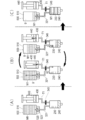
- FIGS. 16A to 16C are diagrams schematically showing the procedure of the filling operation by the chemical filling machine.
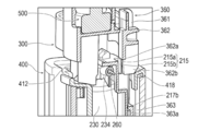
- FIG. 18 is a cross-sectional view showing a state when the chemical liquid filling unit is attached to the chemical liquid filling machine, and is a cross-sectional view taken along arrows 18A-18A in FIG.
- FIG. 18 is a perspective view which shows a mode at the time of mounting
- FIG. 18 shows a mode at the time of mounting
- the present invention is applied to an insulin pump that is a portable drug solution administration device.
- the present invention can be widely applied to various chemical solution administration devices used for the purpose of administering a chemical solution.
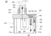
- the chemical solution filling set 10 the chemical solution filling unit 100, the chemical solution storage device 200, the filling adapter 300, the chemical solution filling machine 400, the chemical solution container 500, and the chemical solution administration device 600 will be described.
- FIGS. 1 and 2 are diagrams for explaining the chemical solution filling set 10
- FIG. 3 is a diagram for explaining the chemical solution storage device 200
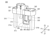
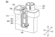
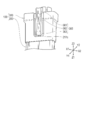
- FIGS. 4 to 7 are diagrams for explaining the filling adapter 300
- FIGS. FIGS. 10 to 14 are diagrams for explaining the chemical solution filling machine 400
- FIGS. 15 and 16 are diagrams for explaining examples of use of the chemical solution filling set 10
- FIGS. FIG. 25 is a diagram for explaining the operation of the lock mechanism 360
- FIG. 25 is a diagram for explaining the drug solution administration device 600.
- the width direction of the chemical liquid filling set 10 (chemical liquid storage device 200, filling adapter 300, chemical liquid filling machine 400) is indicated by the X1 axis-X2 axis, and the depth direction of the chemical liquid filling set 10 is Y1 axis-Y2 axis.
- the height direction of the chemical solution filling set 10 is indicated by the Z1 axis-Z2 axis.
- the chemical solution filling set 10 includes a chemical solution filling unit 100 and a chemical solution filling machine 400 used when the chemical solution storage device 200 is filled with the chemical solution.
- the chemical solution filling unit 100 includes a chemical solution storage device 200 that stores a chemical solution to be administered to a patient, and a filling adapter 300 that is detachably attached to the chemical solution storage device 200.
- the chemical storage device 200 is used as a part constituting a part (disposal part) of the chemical liquid administration device 600 as shown in FIG.
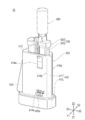
- the filling adapter 300 is an instrument for connecting a chemical solution container 500 (for example, a vial) containing a chemical solution and the chemical solution storage device 200.
- the chemical solution filling machine 400 is an instrument for transferring the chemical solution from the chemical solution container 500 to the chemical solution storage device 200.
- a user who uses the drug solution administration device 600 fills the drug solution storage unit 230 of the drug solution storage device 200 with the drug solution before using the drug solution administration device 600. Do work.
- the user connects the chemical solution container 500 and the chemical solution storage device 200 via the filling adapter 300.
- the user connects the chemical solution storage device 200 and the chemical solution filling machine 400 via the filling adapter 300.
- the flow path includes a main body 510 of the chemical liquid container 500, a first needle tube 321 included in the filling adapter 300, a chemical liquid storage part 230 of the chemical liquid storage device 200, and a first connection port part of the chemical liquid storage part 230.
- first port part corresponds to the “first port part” 232, the second connection port part (corresponding to the “third port part”) 234 of the chemical solution storage unit 230, the tube 260 of the chemical solution storage device 200, the first of the chemical solution storage device 200
- the third needle tube 471, the tube 470 of the chemical solution filling machine 400, and the syringe 430 of the chemical solution filling machine 400 are formed to communicate with each other.
- the user operates the chemical liquid filling machine 400 as described later to transfer the chemical liquid from the chemical liquid container 500 to the chemical liquid storage unit 230. Can be transported (see FIG. 16).
- the user takes out the chemical solution filling unit 100 from a predetermined packaging material or the like.
- the chemical solution container 500 is connected to the filling adapter 300 of the chemical solution filling unit 100 (STEP 1 in FIG. 15).
- the chemical solution filling unit 100 is mounted on the chemical solution filling machine 400 and a filling operation is performed (STEP 2 in FIG. 15).
- the chemical solution filling unit 100 is removed from the chemical solution filling machine 400 (STEP 3 in FIG. 15).
- the user removes the chemical solution container 500 from the filling adapter 300 and then removes the chemical solution storage device 200 from the filling adapter 300.
- the chemical liquid storage device 200 is used as a disposable part of the chemical liquid administration device 600 after being removed from the filling adapter 300 (see FIG. 25).
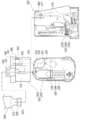
- the chemical solution storage device 200 includes a chemical solution storage unit 230 that stores the chemical solution, and an exterior case 210 that accommodates the chemical solution storage unit 230.
- the exterior case 210 is a housing in which an internal space 210a that can accommodate each component of the chemical solution storage device 200 is formed.
- the exterior case 210 is provided with a projecting housing portion 211 projecting inside the internal space 210a.
- the protruding housing part 211 is provided with a port 213 to which a tube 260 arranged in the internal space 210a is connected.
- a second needle tube 261 is attached to the port 213. As shown in FIG. 8, part of the port 213 and part of the second needle tube 261 are exposed to the outside of the exterior case 210 on the back side of the exterior case 210.
- the outer case 210 is provided with a first lock portion 215 and a second lock portion 216 that regulate the movement of the filling adapter 300 in cooperation with a locking mechanism 360 of the filling adapter 300 described later. It has been.
- the first lock portion 215 includes a contact portion 215a with which the stopper portion 362 of the lock mechanism 360 of the filling adapter 300 is abutted in a state where the filling adapter 300 is attached to the chemical solution storage device 200. And a groove portion 215b extending downward from the contact portion 215a along the height direction of the outer case 210 (the Z1-Z2 direction in FIG. 3).
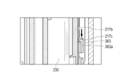
- the second lock portion 216 has a first groove portion 217a extending along the height direction of the outer case 210, and a direction intersecting the first groove portion 217a (direction X1-X2 in the drawing).
- a second groove portion (corresponding to “groove portion”) 217b extending and a third groove portion (corresponding to “groove portion”) 217c extending substantially parallel to the second groove portion 217b are provided.
- the second groove portion 217b is formed above the third groove portion 217c (upper side in FIG. 8) in the height direction of the exterior case 210. Further, between the second groove portion 217b and the third groove portion 217c in the height direction of the outer case 210, they are arranged to face each other along the width direction of the outer case 210 (direction X1-X2 in the figure). A pair of convex portions 218a and 218b are formed. An inclined wall whose thickness gradually decreases toward the upper side of the outer case 210 is formed at the upper end of each convex portion 218a, 218b.
- the drug solution storage device 200 includes a solution feeding mechanism 220 that sends the drug solution to the patient.
- the liquid feeding mechanism 220 includes a chemical liquid storage unit 230, a pusher member 240, and a driving unit 250.
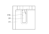
- the chemical solution storage unit 230 includes a storage unit main body 231 in which an internal space 231a that can store a chemical solution is formed, a first connection port unit 232 provided on one end side (the upper side in FIG. 3) of the storage unit main body 231,
- the storage unit main body 231 has a second connection port part 234 provided at a position different from the first connection port part 232.
- the storage unit body 231 has a conical shape with one end tapered.
- the other end side (lower side in FIG. 3) of the storage unit main body 231 is an open end that opens to the outside.
- the gasket 241 of the pusher member 240 is inserted into the internal space 231 a of the storage unit main body 231.
- the first connection port portion 232 is opened upward in FIG.
- a seal member (corresponding to a “first seal member”) 233 is disposed in the first connection port portion 232.
- the seal member 233 is punctured with the first needle tube 321 of the filling adapter 300.
- the second connection port portion 234 is open toward the right in FIG.
- a seal member 235 is disposed on the second connection port portion 234.
- the tube 260 of the chemical solution storage unit 230 is connected to the seal member 235.
- a second needle tube 261 is attached to one end of the tube 260 of the chemical solution storage unit 230.
- the second needle tube 261 is punctured into a seal member (corresponding to a “second seal member”) 333 disposed in the first connection port portion 330 of the filling adapter 300 (see FIG. 2).
- the chemical solution storage device 200 and the filling adapter 300 are connected to each other when provided to the user as the chemical solution filling unit 100, but the first needle tube 321 of the filling adapter 300 is the first connection of the chemical solution storage device 200.
- the seal member 233 disposed in the port portion 232 is held at a position not penetrating.
- the second needle tube 261 of the chemical solution storage device 200 is held at a position that does not penetrate the seal member 333 disposed in the first connection port portion 330 of the filling adapter 300. Is done.
- the user operates the medicinal solution storage device 200 and the filling adapter 300 when filling the medicinal solution storage device 200 with the first needle tube 321 of the filling adapter 300 to the first of the medicinal solution storage device 200.
- the seal member 233 of the connection port portion 232 is penetrated, and further, the second needle tube 261 of the chemical solution storage device 200 is penetrated to the seal member 333 of the first connection port portion 330 of the filling adapter 300.
- the pusher member 240 of the liquid feeding mechanism 220 is attached to the gasket 241 housed in the storage unit main body 231, the feed screw part 242 for moving the gasket 241, and the feed screw part 242.
- a shaft portion 243 and an engagement piece 245 attached to the shaft portion 243.
- the feed screw portion 242 rotates when rotational power is transmitted from the drive portion 250.
- the shaft portion 243 moves along the extending direction (vertical direction in FIG. 3) of the storage portion main body 231 in conjunction with the rotation.
- the gasket 241 moves inside the storage unit main body 231 in conjunction with the movement of the shaft portion 243. If the gasket 241 moves forward (moves upward in FIG. 3) while using the chemical solution administration device 600 (see FIG. 25), the chemical solution is removed from the chemical solution storage unit 230 via the second connection port unit 234. Sent out.
- the engaging piece 245 provided on the shaft portion 243 is configured to be connectable to an engaging portion 483 (see FIG. 10) provided in the chemical liquid filling machine 400. As will be described later, by adjusting the position of the engagement piece 245 in a state where the chemical solution filling unit 100 is mounted on the chemical solution filling machine 400, the amount of the chemical solution (initial filling amount) to be filled in the chemical solution storage unit 230 is adjusted. It is possible.
- the driving part 250 of the liquid feeding mechanism 220 is a mechanism for transmitting rotational power to the feed screw part 242.
- the drive unit 250 includes a gear group 251 that can freely mesh with a gear group 613b (see FIG. 25) included in the reuse unit 610 of the drug solution administration device 600.
- the gear group 251 rotates by receiving rotational power from the gear group 613b of the reuse unit 610 when the drug solution storage device 200 is used as a disposable unit of the drug solution administration device 600 to administer the drug solution to the patient.
- the feed screw portion 242 rotates in conjunction with the rotation of the gear group 251.
- the filling adapter 300 includes an adapter main body 310 to which the first needle tube 321 is attached, and a lock mechanism 360 provided integrally with the adapter main body 310. .
- the adapter main body 310 has a connection part 320 to which the chemical liquid container 500 is connected, a first connection port part (corresponding to a “second port part”) 330 through which the chemical liquid can flow, and a gas g such as air can flow.
- a seal member 333 is disposed on the first connection port portion 330 of the adapter main body 310. As described above, the seal member 333 is pierced with the second needle tube 261 of the drug solution storage device 200. However, when the drug solution filling unit 100 is provided to the user, the second needle tube 261 penetrates the seal member 333. It is held in a position that does not.
- a seal member 353 is disposed on the second connection port portion 350 of the adapter main body 310. As shown in FIG. 5, the third needle tube 471 of the chemical solution filling machine 400 passes through the seal member 353.
- the adapter main body 310 includes a pair of slide guide portions 311a and 311b formed on both side surfaces of the adapter main body 310, an inner surface guide portion 312 formed on the inner surface of the adapter main body 310, And an insertion port 313 formed at the lower end of the adapter main body 310.
- the slide guide portions 311 a and 311 b of the adapter main body 310 are in contact with the side surfaces 214 a and 214 b of the exterior case 210 of the chemical solution storage device 200 when the filling adapter 300 is attached to the chemical solution storage device 200.
- the inner surface guide portion 312 of the adapter main body 310 is disposed so as to contact the back surface of the exterior case 210 of the chemical solution storage device 200.
- the slide guide portions 311 a and 311 b and the inner surface guide portion 312 guide the slide movement of the adapter main body 310 when the adapter main body 310 is moved relative to the outer case 210.
- connection part 320 of the adapter main body part 310 is configured such that the lid part 520 of the chemical solution container 500 can be inserted.
- connection part 320 it protrudes and arrange
- the lid portion 520 of the chemical solution container 500 is inserted into the connection portion 320, the lid portion 520 is temporarily fixed to the connection portion 320.
- the first needle tube 321 passes through the seal member 523 disposed in the lid portion 520 of the chemical solution container 500 when the lid portion 520 is connected to the connection portion 320.
- the main body 510 of the chemical solution container 500 is communicated with the chemical solution storage unit 230 via the first needle tube 321 (see FIG. 2).
- the first connection port portion 330 and the second connection port portion 350 provided in the adapter main body 310 communicate with each other through a flow passage 341 defined inside the adapter main body 310.
- the flow passage 341 is formed by covering the space formed inside the adapter main body 310 with a lid member 343 disposed on the upper side of the adapter main body 310.
- the lid member 343 is fixed to the adapter main body 310 by welding or adhesion.
- a ventilation filter 345 is disposed in the flow passage 341 of the adapter main body 310.
- the ventilation filter 345 allows passage of a gas such as air while blocking passage of a liquid such as a chemical solution.
- the vent filter 345 prevents the chemical solution from flowing into the chemical solution filling machine 400 via the flow passage 341 when the chemical solution is stored in the chemical solution storage device 200 using the chemical solution filling device 400 ( (See FIG. 16C).
- the lock mechanism 360 provided in the adapter main body 310 includes a lever part 361, a stopper part 362, and a claw part 363.
- the lever portion 361 of the lock mechanism 360 is configured by a plate-like member that is recessed inside the adapter main body 310.
- the stopper portion 362 of the lock mechanism 360 has portions 362a and 362b protruding inside the adapter main body 310 (see FIG. 18). A portion 362a of the stopper portion 362 that protrudes to the inside of the adapter main body 310 regulates the movement of the filling adapter 300 in cooperation with the first lock portion 215 of the chemical solution storage device 200, as will be described later.
- the claw portion 363 of the lock mechanism 360 is formed on the lower end side of the lock mechanism 360. As shown in FIG. 6, the claw portion 363 has a protruding portion 363 a that protrudes inside the adapter main body portion 310. The protruding portion 363a of the claw portion 363 can be hooked with respect to the respective groove portions 217b and 217c (see FIG. 8) of the second lock portion 216 of the chemical solution storage device 200.
- the lock mechanism 360 is formed on the back surface of the adapter main body 310 (a surface disposed opposite to the back surface side of the chemical solution storage device 200). Further, in the adapter main body 310, a notch 365 for moving the lock mechanism 360 is formed around a portion where the lock mechanism 360 is formed.
- the lock mechanism 360 is connected to the adapter main body 310 via a lever portion 361 located on the upper side of the lock mechanism 360.
- the lock mechanism 360 is movable (oscillated) in the direction indicated by the arrow a starting from the lever portion 361. To do. Further, when the pressing of the lever portion 361 is released, the lock mechanism 360 moves in the direction indicated by the arrow a ′ and returns to the original position before the pressing.
- an end portion (downward end portion in FIG. 8) 362a of the lock portion 360 of the lock mechanism 360 is formed on the first lock portion 215 as shown in FIG. It abuts against the abutment portion 215a. Further, when the chemical solution filling unit 100 is provided to the user, the claw portion 363 of the lock mechanism 360 is hooked on the second groove portion 217 b of the second lock portion 216.
- the relative movement of the filling adapter 300 with respect to the chemical solution storage device 200 is regulated by the contact between the predetermined portion 362a of the stopper portion 362 and the contact portion 215a and the hook of the claw portion 363 with respect to the second groove portion 217b.
- the filling adapter 300 can be attached to the chemical solution storage device 200 by moving relatively close to the chemical solution storage device 200 as indicated by an arrow A in FIG. Moreover, the filling adapter 300 can be removed from the chemical solution storage device 200 by being moved away from the chemical solution storage device 200 as indicated by an arrow A ′ in FIG. 8. In addition, when removing the filling adapter 300 from the chemical
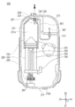
- FIG. 9 shows a state where the filling adapter 300 is mounted on the chemical storage device 200.
- the chemical solution filling unit 100 according to the present embodiment is provided to the user with the filling adapter 300 mounted on the chemical solution storage device 200 in this manner. Further, as described above, the chemical liquid filling unit 100 is provided to the user in a state where the relative movement of the filling adapter 300 with respect to the chemical liquid storage device 200 is restricted.
- the filling adapter 300 does not penetrate the seal member 233 in which the first needle tube 321 on the filling adapter 300 side is disposed in the chemical solution storage unit 230, And the 2nd needle tube 261 by the side of the chemical
- the first needle tube 321 on the filling adapter 300 side is connected to the drug solution storage unit 230.
- the chemical solution filling machine 400 includes an outer case 410 that houses each component of the chemical solution filling machine 400, a filling mechanism 420 that sends the chemical solution to the chemical solution storage device 200, and a second filling adapter 300.
- a filling amount adjusting mechanism 480 that adjusts the amount of the chemical solution stored in the storage device 200 and a holding mechanism 490 that holds the chemical solution storage device 200 in a fixed position with respect to the chemical solution filling machine 400 are provided.
- the exterior case 410 of the chemical solution filling machine 400 has a main body 411 and a pedestal 415.
- the pedestal portion 415 supports the chemical solution filling machine 400 with respect to the floor surface, the table or the like, and makes the chemical solution filling machine 400 upright.
- the main body portion 411 is formed to extend upward from the pedestal portion 415 and has a rounded side surface.
- a filling amount adjusting mechanism 480 and a holding mechanism 490 are disposed in the main body portion 411, and each component of the filling mechanism 420 is disposed in the pedestal portion 415.
- An upper opening 412 for inserting the chemical solution filling unit 100 is formed at the upper end of the exterior case 410 (see FIG. 1).
- a side opening 413 from which the lever portion 453 of the filling mechanism 420 protrudes is formed on the side surface of the outer case 410.
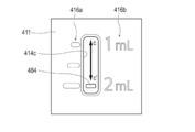
- a window portion 414c for exposing the display piece 484 of the filling amount adjusting mechanism 480 to the outside, and a window portion 414d for exposing the rotary dial 485 of the filling amount adjusting mechanism 480 to the outside are formed.
- the lever portion 491a of the holding mechanism 490 is exposed to the outside in a state where the chemical solution filling unit 100 is mounted on the chemical solution filling machine 400.
- the window part 414a to be made and a window part 414e that makes a part of the chemical solution filling unit 100 visible from the outside are formed.
- the filling mechanism 420 includes a syringe 430, a pusher member 440, and a drive unit 450.
- the syringe 430 includes a syringe body 431 having an internal space 431a capable of storing a gas g such as air, and a port portion 432 provided in the syringe body 431.
- the port part 432 of the syringe 430 is connected to a tube 470 accommodated in the outer case 410.
- a gas g such as air sent from the syringe 430 via the port portion 432 is sent to the second connection port portion 350 of the filling adapter 300 via the tube 470 and the third needle tube 471.
- the pusher member 440 includes a gasket 441 housed in the internal space 431a of the syringe body 431, and a shaft portion 442 attached to the gasket 441.
- the shaft portion 442 is connected to the link mechanism 452 of the driving portion 450.
- the shaft portion 442 moves in conjunction with an operation for gripping the lever portion 453 and an operation for releasing the gripping.
- the gasket 441 disposed at the tip of the shaft portion 442 moves along the extending direction (the left-right direction in FIG. 10) in the internal space 431a of the syringe body 431 as the shaft portion 442 moves.
- the drive unit 450 of the filling mechanism 420 is connected to the pusher member 440 via a biasing member 451 that applies a biasing force to the shaft portion 442 of the pusher member 440, a predetermined link mechanism 452, and the link mechanism 452.
- the biasing member 451 can be constituted by a known coil spring, for example.
- the urging member 451 applies an urging force (elastic force) in the direction of the arrow b ′ in FIG.
- the user moves the lever portion 453 connected to the urging member 451 via the link mechanism 452 in the direction of the arrow b in the figure, thereby resisting the urging force of the urging member 451 and pushing the member 440.
- a gas g such as air accommodated in the syringe body 431 is sent to the tube 470 via the port portion 432.
- the operating force (gripping force) of the lever portion 453 is loosened, the pusher member 440 moves backward (moves in the right direction in the figure) by the biasing force of the biasing member 451.
- the filling mechanism 420 moves the pusher member 440 against the urging force of the urging member 451 when transferring the chemical liquid from the chemical liquid filling machine 400 to the chemical liquid storage device 200 as described above. Since the (arrow b direction) and the operation direction of the lever portion 453 (arrow b direction) match, the user can easily grasp the progress of the filling operation sensuously.
- the filling amount adjusting mechanism 480 includes a feed screw portion 481, a movable member 482 connected to the feed screw portion 481, and an engagement piece 245 provided in the liquid feed mechanism 220 of the chemical solution storage device 200. (Refer to FIG. 3) having an engaging portion 483 that can be connected, a display piece 484 that indicates the initial filling amount of the drug solution storage device 200, and a rotary dial 485 for operating the feed screw portion 481. .
- the rotation dial 485 rotates the feed screw portion 481 and moves the movable member 482 connected to the feed screw portion 481 when a rotation operation is performed by the user. Specifically, when the rotary dial 485 is rotated in the direction of the arrow r shown in FIGS. 10 and 11, the movable member 482 moves in the direction of the arrow c (upward), and the rotary dial 485 is rotated in the direction of the arrow r ′. Then, the movable member 482 moves in the direction of arrow c ′ (downward).
- the engaging portion 483 is connected to an engagement piece 245 provided in the liquid feeding mechanism 220 of the chemical liquid storage device 200 in a state where the chemical liquid filling unit 100 is mounted on the chemical liquid filling machine 400 (see FIG. 3).
- the engaging portion 483 also moves together with the movable member 482.
- the shaft portion 243 of the liquid feeding mechanism 220 to which the engaging piece 245 is attached also moves (see FIG. 3).
- the movement of the movable member 482 is converted into the movement of the shaft portion 243 of the liquid feeding mechanism 220.
- the shaft portion 243 of the liquid feeding mechanism 220 is moved, and the gasket 241 is moved together with the shaft portion 243, whereby the volume of the chemical solution storage unit 230 that can be filled with the chemical solution is adjusted.
- the rotary dial 485 is exposed to the outside through the window 414d. For this reason, the user can easily rotate the rotary dial 485 with fingers.
- the display piece 484 moves in the direction of arrow c.
- the user can visually confirm that the volume of the chemical liquid that can be filled in the chemical liquid storage unit 230 is reduced by moving the display piece 484 in the direction of the arrow c.
- the display piece 484 is moved in the direction of the arrow c ′.
- the user can visually confirm that the volume of the chemical liquid that can be filled in the chemical liquid storage unit 230 is increased by moving the display piece 484 in the direction of the arrow c ′.
- a scale 416a and a number 416b indicating a reading of the scale 416a are attached around the window 414c exposing the display piece 484.
- the user confirms the scale 416a and the numeral 416b based on the position of the display piece 484, thereby starting the initial filling amount of the drug solution that can be filled in the drug solution storage unit 230 (the drug solution administration using the drug solution administration device 600 is started).
- the outer surface of the main body 411 of the exterior case 410 is relatively large and has a scale 416a and a numeral 416b. For this reason, the user can easily grasp the initial filling amount of the chemical solution visually.
- the window part 414b formed in the main body part 411 of the exterior case 410 makes it possible to visually recognize the storage part main body 231 of the chemical solution storage device 200 from the outside. Since the user can visually check the progress of the filling operation of the storage unit main body 231 through the window 414b while the storage unit main body 231 is filled with the chemical solution, it is necessary for the storage unit main body 231. It can prevent suitably that the above chemical
- the holding mechanism 490 of the chemical solution filling machine 400 includes a predetermined holding member 491 and a biasing member 493 that applies a biasing force to the holding member 491.
- the holding member 491 prevents the chemical solution storage device 200 from being displaced by pressing the chemical solution storage device 200 in a state where the chemical solution filling unit 100 is mounted on the chemical solution filling machine 400.
- the biasing member 493 can be constituted by a known coil spring, for example.
- the biasing member 493 applies a biasing force (elastic force) to the holding member 491 along the direction indicated by the arrow d in FIG.
- the holding member 491 receives the urging force applied by the urging member 493 and presses the chemical solution storage device 200 inserted into the outer case 410.
- the holding member 491 has a lever portion 491a exposed from a window portion 414a formed in the main body portion 411 of the exterior case 410.
- a push-up member 494 that operates when the chemical liquid filling unit 100 is removed from the chemical liquid filling machine 400 and a biasing member 495 that applies a biasing force to the push-up member 494 are disposed inside the main body 411 of the exterior case 410. ing.
- the biasing member 495 is pressed and contracted by the chemical solution storage device 200 in the direction of the arrow e ′ (downward in the drawing).
- the biasing member 495 can be comprised from a well-known coil spring, for example.
- the user moves the lever portion 491a exposed from the window portion 414a in the direction of the arrow d 'in FIG.
- the pressing of the chemical storage device 200 by the urging force of the urging member 493 is released.
- the urging member 495 extends in the direction of arrow e (upward in the drawing) and is filled with the chemical from the outer case 410 of the chemical filling machine 400.
- the upper side of the unit 100 (the upper side of the filling adapter 300) is protruded. Thereby, the user can extract the chemical filling unit 100 from the outer case 410 of the chemical filling machine 400.
- the chemical solution filling machine 400 includes a restriction release unit 418 that releases the restriction by the lock mechanism 360 when the chemical solution filling unit 100 is attached to the chemical solution filling machine 400.
- the regulation release part 418 is configured by a rib (convex part) formed in the outer case 410 of the chemical liquid filling machine 400.
- the restriction release portion 418 is formed at a position facing the lock mechanism 360 of the filling adapter 300 in the vicinity of the upper opening 412 of the outer case 410.
- the restriction release portion 418 has a shape protruding into the outer case 410.
- each sealing member 233, 235, 333, and 353 is not particularly limited.
- various materials such as natural rubber, butyl rubber, isoprene rubber, butadiene rubber, styrene-butadiene rubber, and silicone rubber are used.
- elastic materials such as rubber materials, various thermoplastic elastomers such as polyurethane, polyester, polyamide, olefin, and styrene, and mixtures thereof.
- each of the needle tubes 261, 321, and 471 for example, a known needle member or the like in which a flow path is formed can be used as appropriate, and the material, size, shape, and the like are not particularly limited. .
- each tube 260,470 which concerns on this embodiment can utilize suitably tubes (hollow member), such as metal and resin.
- the materials of the exterior cases 210 and 410 and the adapter main body 310 according to the present embodiment are not particularly limited, and examples thereof include resin materials such as polypropylene, polyethylene terephthalate, polymethyl methacrylate, and polycarbonate.
- a chemical solution container 500 includes a main body portion 510 that stores a chemical solution to be administered to a patient, a lid portion 520 configured to be connected to and separated from the filling adapter 300, and a lid portion 520. And a seal member 523 arranged.
- the chemical solution container 500 is constituted by, for example, a known vial.
- the chemical liquid stored in the chemical liquid container 500 is, for example, insulin.
- medical solution container 500 is formed transparent or semi-transparent so that the residual amount etc. of an internal chemical
- a user who uses the chemical solution administration device 600 sets the chemical solution container 500 in the chemical solution filling unit 100 when using it.
- the user causes the first needle tube 321 provided in the filling adapter 300 to penetrate the seal member 523 of the drug solution container 500.
- the inside of the chemical solution container 500 and the chemical solution storage unit 230 of the chemical solution storage device 200 are communicated with each other via the first needle tube 321 (see FIG. 2).
- the user takes out the chemical solution filling unit 100 from a predetermined packaging material or the like when administering the chemical solution using the chemical solution administration device 600.
- the position of the filling adapter 300 is such that the first needle tube 321 on the filling adapter 300 side does not penetrate the seal member 233 on the chemical solution storage unit 230 side and the first position on the chemical solution storage device 200 side in the state where the filling adapter 300 is taken out from the packaging material.
- the two-needle tube 261 is held at a position that does not penetrate the seal member 333 on the filling adapter 300 side (non-penetrating position P1).
- the user attaches the chemical solution container 500 to the chemical solution filling unit 100 (see STEP 1 in FIG. 15). Then, the user attaches the chemical solution filling unit 100 to the chemical solution filling machine 400.
- the position of the filling adapter 300 is such that the first needle tube 321 on the filling adapter 300 side penetrates the seal member 233 on the chemical solution storage unit 230 side and The second needle tube 261 on the storage device 200 side moves to a position (penetration position P2) that penetrates the seal member 333 on the filling adapter 300 side. Further, the position of the filling adapter 300 is held at the penetration position P2. In this state, the user operates the chemical solution filling machine 400 to transfer the chemical solution from the chemical solution container 500 to the chemical solution storage unit 230 (see STEP 2 in FIG. 15).
- the penetration of the third needle tube 471 into the seal member 353 disposed in the second connection port portion 350 of the filling adapter 300 was performed by attaching the chemical solution filling unit 100 to the chemical solution filling machine 400. Done when.
- the user removes the chemical solution filling unit 100 from the chemical solution filling machine 400 after the filling of the chemical solution into the chemical solution storage unit 230 is completed (see STEP 3 in FIG. 15). Thereafter, the chemical solution container 500 is removed from the filling adapter 300, and the filling adapter 300 is removed from the chemical solution storage device 200. As shown in FIG. 25, the chemical solution storage device 200 filled with the chemical solution is connected to other members (reuse unit 610, cradle 630) that constitute the chemical solution administration device 600. By performing the above procedure, the user can start the administration of the chemical solution using the chemical solution administration device 600.
- FIG. 16A shows a state in which the chemical solution filling unit 100 is mounted on the chemical solution filling machine 400 at the start of the filling operation.
- the main body 510 of the chemical solution container 500 is connected to the chemical solution storage unit 230 of the chemical solution storage device 200 via the first needle tube 321. Moreover, the chemical
- the filling channel T1 includes the tube 470 of the chemical solution filling machine 400, the third needle tube 471 of the chemical solution filling machine 400, the second connection port portion 350 of the filling adapter 300, the flow passage 341 of the filling adapter 300, and the first connection of the filling adapter 300. It is comprised by the port part 330, the 2nd needle tube 261 of the chemical
- the chemical solution container 500 is connected to the filling adapter 300 in a state where the lid portion 520 is disposed below in the vertical direction (see FIG. 1). Thereby, the lid 520 side (the lower side of FIG. 16A) of the main body 510 of the chemical liquid container 500 is filled with the chemical M1, and the bottom side of the main body 510 of the chemical liquid container 500 (FIG. 16). On the upper side of (A), a space capable of holding a gas g such as air is formed.
- the user performs an operation of transferring the chemical solution from the chemical solution container 500 to the chemical solution storage unit 230.
- a gas g such as air is pumped to the chemical solution container 500 via the filling flow path T1, the chemical solution storage unit 230, and the first needle tube 321 of the chemical solution filling machine 400.
- the chemical solution container 500 is pressurized by a gas g such as pressure-fed air.
- the gas g such as air fed to the chemical liquid container 500 moves in the main body 510 of the chemical liquid container 500 and stays on the bottom side of the main body 510 (upper side in FIG. 16B).
- the user releases the grip of the lever portion 453 of the chemical liquid filling machine 400 while the inside of the chemical liquid container 500 is pressurized.
- the pusher member 440 of the chemical solution filling machine 400 is moved backward (moved in the direction of the arrow b ′ in FIG. 10) by the urging force of the urging member 451.
- a negative pressure suction pressure
- the chemical solution M1 in the chemical solution container 500 moves to the chemical solution storage unit 230.
- the holding and release of the lever portion 453 of the chemical solution filling machine 400 are repeated to alternately perform pressurization and decompression (release), thereby storing the chemical solution.
- the unit 230 can be filled with a desired amount of the chemical solution M1.
- the user removes the chemical liquid filling unit 100 from the chemical liquid filling machine 400.
- the user removes the filling adapter 300 from the chemical solution storage device 200.
- the user pulls out the first needle tube 321 of the filling adapter 300 from the seal member 233 of the chemical solution storage unit 230.
- the seal member 233 of the chemical solution storage unit 230 maintains a good sealing property and prevents the chemical solution M1 from leaking from the first connection port unit 232 of the chemical solution storage unit 230.
- the user pulls out the second needle tube 261 on the chemical solution storage device 200 side from the seal member 333 of the filling adapter 300.
- the chemical solution storage device 200 can be filled with a desired amount of the chemical solution M1.
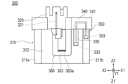
- FIG. 17 shows a state when the chemical solution filling unit 100 is mounted on the chemical solution filling machine 400.
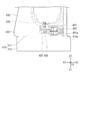
- FIG. 18 shows a cross-sectional view taken along arrows 18A-18A shown in FIG. 19 and 20 are perspective views showing a procedure for mounting the chemical solution filling unit 100 to the chemical solution filling machine 400 from the state shown in FIG. 21 to 23 are views showing a procedure for mounting the chemical solution filling unit 100 to the chemical solution filling machine 400, and correspond to the cross-sectional view shown in FIG.
- FIG. 24 is a cross-sectional view showing a main part of the lock mechanism 360.
- the filling adapter 300 is disposed at the non-penetrating position P1.
- the relative movement of the filling adapter 300 relative to the drug solution storage device 200 is restricted by the lock mechanism 360. More specifically, as shown in FIG. 18, a part 362a of the stopper portion 362 of the lock mechanism 360 is in contact with the contact portion 215a of the first lock portion 215, and the claw portion 363 of the lock mechanism 360 is the second groove portion. It is in a state of being hooked by 217b.
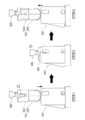
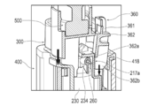
- the restriction by the lock mechanism 360 can be released by inserting the chemical solution filling unit 100 into the chemical solution filling machine 400 from the state shown in FIG. 17 as shown in FIG. As shown in FIG. 21, the stopper portion 362 of the lock mechanism 360 brings the lower end portion 362 b into contact with the restriction release portion 418 of the chemical liquid filling machine 400 when the filling adapter 300 is pushed into the chemical liquid filling machine 400.
- the restriction release portion 418 releases the contact between the stopper portion 362 and the first lock portion 215 by pushing the stopper portion 362 as indicated by an arrow a ′. Thereby, a part 362 a of the stopper portion 362 enters the groove portion 215 b of the first lock portion 215.
- the claw portion 363 of the lock mechanism 360 comes out of the second groove portion 217b when the stopper portion 362 is pushed in as indicated by an arrow a '(see FIG. 7).
- the filling is performed.
- the adapter 300 is in a state in which it can slide relative to the drug solution storage device 200.
- the filling adapter 300 can be moved to the penetrating position P2.
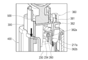
- the stopper portion 362 of the lock mechanism 360 moves along the first groove portion 217a.
- the claw portion 363 of the lock mechanism 360 moves to the third groove portion 217c and is caught by the third groove portion 217c (see FIG. 7).
- the filling adapter 300 moves to this position, the movement is restricted by the claw portion 363. Therefore, the filling adapter 300 is held at the penetration position P2.
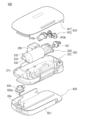
- the chemical solution administration device 600 includes a reuse unit 610, a chemical solution storage device (disposal unit) 200, and a cradle 630.
- the reuse unit 610 includes a lid 611 and a drive unit 613 accommodated inside the lid 611.
- the lid body 611 is configured to be removable from the outer case 210 of the chemical solution storage device 200.
- the drive unit 613 includes a motor 613a and a gear group 613b.
- the motor 613a can be configured by, for example, a known stepping motor.
- the gear group 613b is rotationally driven by a motor 613a.
- the gear group 613b is configured to be freely meshed with a gear group 251 provided in the chemical solution storage device 200.
- a battery box 280 including a battery serving as a power source for driving the motor 613a is disposed. Note that the battery box 280 may be disposed in the reuse unit 610.
- the cradle 630 includes a main body portion 631, a catheter port 634, and an administration port 635.
- the administration port 635 is provided with a needle portion 635a for administering the drug solution to the patient.
- the chemical solution administration device 600 is configured by mutually connecting a reuse unit 610, a chemical solution storage device 200 in which a chemical solution storage unit 230 is filled with a chemical solution, and a cradle 630.
- the cradle 630 is attached (fixed) to a part of the patient's body (for example, the abdomen or extremities).
- a predetermined operation command is transmitted by a controller or the like (not shown) to operate the motor 613a.
- the gear group 613b of the reuse unit 610 operates, and the gear group 251 of the chemical storage device 200 operates in conjunction with the operation of the gear group 613b.
- the pusher member 240 of the liquid feeding mechanism 220 of the drug solution storage device 200 starts to move, the drug solution is administered to the patient via the needle portion 635a.
- the chemical solution storage device 200 is removed from the reuse unit 610.
- the chemical solution storage device 200 can be discarded after use, and the reuse unit 610 can be reused when separately administering the chemical solution.
- the chemical solution filling unit 100 includes the chemical solution storage device 200 having the chemical solution storage unit 230 that stores the chemical solution, the filling adapter 300 that is detachably attached to the chemical solution storage device 200, and the chemical solution storage. And a lock mechanism 360 that restricts relative movement of the filling adapter 300 with respect to the tool 200.
- the chemical storage device 200 includes an exterior case 210 that accommodates the chemical storage unit 230, a first connection port unit 232 provided in the chemical storage unit 230, and a seal member 233 disposed in the first connection port unit 232. ,have.
- the filling adapter 300 includes a first needle tube 321 that is connected to the chemical solution container 500 that stores the chemical solution, and is punctured by the seal member 233, and an adapter main body 310 to which the first needle tube 321 is attached. ing.
- the lock mechanism 360 is configured so that the first needle tube 321 does not pass through the seal member 233 in the relative position of the adapter main body 310 with respect to the outer case 210 in a state where the filling adapter 300 is attached to the chemical solution storage device 200.
- the position P1 and the first needle tube 321 can be held at the penetrating position P2 through which the seal member 233 passes.
- the user fills the chemical solution storage device 200 before the filling of the chemical solution 200 is started in a state where the filling adapter 300 is attached to the chemical solution storage device 200. It is possible to prevent the first needle tube 321 of the adapter 300 from penetrating the seal member 233 of the chemical solution storage unit 230. Further, the user can penetrate the first needle tube 321 of the filling adapter 300 with respect to the seal member 233 by a simple operation of changing the relative position of the filling adapter 300 with respect to the drug solution storage device 200.
- the medicinal solution filling unit 100 can prevent the sealing performance of the seal member 233 of the medicinal solution storage unit 230 from being deteriorated, and allows the first needle tube 321 to penetrate the sealing member 233 of the medicinal solution storage unit 230. Work can be done easily.
- the lock mechanism 360 is provided integrally with the filling adapter 300, releases the restriction in accordance with the operation of sliding the filling adapter 300 relative to the chemical storage device 200, and moves from the non-penetrating position P1 to the penetrating position. Allows movement to P2. For this reason, the user can penetrate the first needle tube 321 with respect to the seal member 233 by a simple operation of sliding the filling adapter 300 with respect to the drug solution storage device 200.
- the lock mechanism 360 includes a claw portion 363 that restricts relative movement of the filling adapter 300 with respect to the chemical solution storage device 200 by being caught in the grooves 217b and 217c formed in the outer case 210 of the chemical solution storage device 200. Yes.
- the chemical solution filling unit 100 can restrict the movement of the filling adapter 300 with a simple configuration in which the claw portion 363 is hooked with respect to the grooves 217b and 217c, and the claw portion 363 with respect to the grooves 217b and 217c.
- limiting of the movement of the filling adapter 300 can be cancelled
- the lock mechanism 360 has a lever portion 361 that releases the catch of the claw portion 363 with respect to the groove portions 217b and 217c in accordance with the pressing operation. For this reason, the user can easily release the hook of the claw portion 363 from the groove portions 217b and 217c by operating the lever portion 361.
- the filling adapter 300 is formed in the adapter main body 310 and is disposed in the flow passage 341 capable of flowing the gas g such as air, the first connection port portion 330 communicating with the flow passage 341, and the first connection port portion 330.
- the sealing member 333 is provided.
- the chemical storage device 200 includes a second connection port 234 provided at a position different from the first connection port 232 in the chemical storage 230, a tube 260 connected to the second connection port 234, a tube And a second needle tube 261 attached to 260.
- the second needle tube 261 does not penetrate the seal member 333, and the relative position of the adapter main body 310 with respect to the outer case 210
- the seal member 333 is penetrated.
- the user can prevent the second needle tube 261 from penetrating the seal member 333 of the filling adapter 300 before the filling of the chemical solution into the chemical solution storage device 200 is started, and the sealing property of the seal member 333 can be improved. Can keep good.
- the user can penetrate the second needle tube 261 of the chemical solution storage device 200 through the seal member 333 by a simple operation of changing the relative position of the filling adapter 300 with respect to the chemical solution storage device 200.
- the chemical solution filling set 10 includes a chemical solution filling unit 100 and a chemical solution filling machine 400 to which the chemical solution filling unit 100 is detachably attached.
- medical solution filling machine 400 has the regulation cancellation
- the filling adapter 300 is configured to be detachable from the chemical liquid storage device 200 having the chemical liquid storage unit 230 that stores the chemical liquid.
- the filling adapter 300 contains a lock mechanism 360 that regulates relative movement of the filling adapter 300 with respect to the chemical solution storage device 200, an adapter main body 310 that is attached to an exterior case 210 provided in the chemical solution storage device 200, and a chemical solution.
- the first needle tube 321 is connected to the chemical solution container 500 and punctured into the seal member 233 provided in the chemical solution storage unit 230.
- the lock mechanism 360 is configured so that the first needle tube 321 does not pass through the seal member 233 in the relative position of the adapter main body 310 with respect to the outer case 210 in a state where the filling adapter 300 is attached to the chemical solution storage device 200.
- the position P1 and the first needle tube 321 are configured to be held at a penetrating position P2 penetrating the seal member 233.
- the user fills the chemical solution storage device 200 in a state in which the filling adapter 300 is attached to the chemical solution storage device 200 before starting to fill the chemical solution.
- the 300 first needle tubes 321 can be prevented from penetrating the seal member 233 of the chemical solution storage unit 230. Further, the user can penetrate the first needle tube 321 of the filling adapter 300 with respect to the seal member 233 by a simple operation of changing the relative position of the filling adapter 300 with respect to the drug solution storage device 200.
- the medicinal solution filling unit 100 can prevent the sealing performance of the seal member 233 of the medicinal solution storage unit 230 from being deteriorated, and allows the first needle tube 321 to penetrate the sealing member 233 of the medicinal solution storage unit 230. Work can be done easily.
- the shape of the lock mechanism, the connection (linkage) structure for restricting movement, the positional relationship with other members, etc. are not particularly limited.
- the form which provided the locking mechanism in the filling adapter was illustrated, you may provide a locking mechanism in a chemical
- the lock mechanism may be configured to release the restriction by moving the drug solution storage device with respect to the filling adapter.
- medical solution storage device is utilized as a lock mechanism, and the relative movement of the filling adapter and the chemical solution storage device is regulated via the lock mechanism, or each member Or the position may be held.
- the filling adapter only needs to be configured to connect the chemical solution storage unit and the chemical solution container via at least the first needle tube, and the second needle tube to be connected to the chemical solution filling machine is not provided. Also good. Further, the filling of the chemical solution may be performed by manually operating the liquid feeding mechanism (pushing member) of the chemical solution storage device without using the chemical solution filling machine, for example.
- the non-penetrating position described in the embodiment may be set to a position where a part of the needle tube is punctured (inserted) into the seal member.
- each of the penetrating position and the non-penetrating position is not limited to a single position. For example, a plurality of positions may be set as the penetrating position, or a plurality of positions may be set as the non-penetrating position. May be.
- the chemical liquid filling unit, the chemical liquid filling set, and the filling adapter are not limited to the contents described in the specification, and the shape, material, arrangement, connection form of the members, and the like can be changed as appropriate. Is possible.
Landscapes
- Health & Medical Sciences (AREA)
- Veterinary Medicine (AREA)
- Animal Behavior & Ethology (AREA)
- Public Health (AREA)
- Life Sciences & Earth Sciences (AREA)
- General Health & Medical Sciences (AREA)
- Pharmacology & Pharmacy (AREA)
- Engineering & Computer Science (AREA)
- Vascular Medicine (AREA)
- Anesthesiology (AREA)
- Biomedical Technology (AREA)
- Heart & Thoracic Surgery (AREA)
- Hematology (AREA)
- Fluid Mechanics (AREA)
- Physics & Mathematics (AREA)
- Dermatology (AREA)
- Infusion, Injection, And Reservoir Apparatuses (AREA)
- Medical Preparation Storing Or Oral Administration Devices (AREA)
Abstract
[Problem] To provide: a drug solution filling unit that is able to prevent deterioration in the seal performance of a seal member for a drug solution reservoir part while facilitating an operation of piercing the seal member for the drug solution reservoir part with a needle tube; a drug solution filling set; and a filling adapter. [Solution] This drug solution filling unit 100 is provided with: a drug solution reservoir instrument 200 having a drug solution reservoir part 230 in which a drug solution is stored; a filling adapter 300 that is detachably mounted to the drug solution reservoir instrument; and a lock mechanism 360 that restricts the movement of the filling adapter relative to the drug solution reservoir instrument, wherein in a state in which the filling adapter is mounted to the drug solution reservoir instrument, the lock mechanism is able to hold the relative position of an adapter body 310 with respect to an exterior case 210 at a non-piercing position where the seal member is not pierced with a first needle tube and at a piercing position where the seal member is pierced with the first needle tube.
Description
本発明は、薬液投与装置に使用される薬液貯蔵具へ薬液を充填する薬液充填ユニット、薬液充填セット、および充填アダプタに関する。
The present invention relates to a chemical solution filling unit, a chemical solution filling set, and a filling adapter for filling a chemical solution storage device used in a chemical solution administration device.
糖尿病患者等への薬液(例えば、インスリン)の投与に使用される医療機器として、患者の身体や衣服等に取り付けた状態で持ち運びできる携帯型の薬液投与装置(いわゆる、インスリンポンプ)が知られている。
2. Description of the Related Art As a medical device used for administration of a drug solution (for example, insulin) to a diabetic patient or the like, a portable drug solution administration device (so-called insulin pump) that is portable while attached to a patient's body or clothes is known. Yes.
従来、携帯型の薬液投与装置としては、特許文献1に記載されているようなものが存在する。特許文献1に記載されている薬液投与装置は、薬液を貯蔵する薬液貯蔵部と、薬液貯蔵部から薬液を送出するプランジャ等の送液機構と、を備えている。
Conventionally, there are devices as described in Patent Document 1 as portable drug solution administration devices. The chemical solution administration device described in Patent Document 1 includes a chemical solution storage unit that stores a chemical solution, and a liquid feeding mechanism such as a plunger that sends out the chemical solution from the chemical solution storage unit.
一般的に、薬液投与装置は、使用者の手元に届く際、薬液貯蔵部に薬液が充填されていない。このため、使用者は、薬液の投与に際し、薬液を収容した薬液容器(例えば、バイアル瓶)と薬液投与装置の薬液貯蔵部を接続して、薬液容器から薬液貯蔵部へ薬液を移送する作業を行う。
Generally, when the chemical solution administration device reaches the user, the chemical solution storage unit is not filled with the chemical solution. For this reason, when administering the chemical solution, the user connects the chemical solution container (for example, vial) containing the chemical solution and the chemical solution storage unit of the chemical solution administration device, and transfers the chemical solution from the chemical solution container to the chemical solution storage unit. Do.
また、上記のように薬液容器から薬液貯蔵部へ薬液を移送する作業を行う際、薬液容器と薬液貯蔵部は、薬液が流通可能な送液用の流路を介して流体連通される。例えば、送液用の流路としては、薬液容器を封止するシール部材と薬液貯蔵部を封止するシール部材に貫通可能な針管を用いることができる。
Further, when the operation of transferring the chemical solution from the chemical solution container to the chemical solution storage unit as described above is performed, the chemical solution container and the chemical solution storage unit are in fluid communication with each other via a liquid-feeding channel through which the chemical solution can flow. For example, a needle tube that can penetrate the seal member that seals the chemical solution container and the seal member that seals the chemical solution storage section can be used as the flow path for liquid feeding.
しかしながら、薬液貯蔵部のシール部材に針管を貫通させた状態が比較的長期に亘って維持されると、シール部材において針管が貫通した部位(針傷周辺)のシール性(気密性)が低下してしまう。このため、薬液貯蔵部のシール部材に対して針管を貫通させる作業は、薬液貯蔵部へ薬液を移送させる作業の直前に行うことが望ましい。
However, if the state in which the needle tube is passed through the seal member of the chemical solution storage unit is maintained for a relatively long period of time, the sealing performance (air tightness) of the portion of the seal member through which the needle tube passes (around the needle wound) decreases. End up. For this reason, it is desirable that the operation of penetrating the needle tube with respect to the sealing member of the chemical solution storage unit is performed immediately before the operation of transferring the chemical solution to the chemical solution storage unit.
また、仮に、薬液貯蔵部と針管とが別個に分離された状態で使用者に提供されると、使用者は、自身の手指で針管を取り扱わざるを得なくなるため、薬液貯蔵部のシール部材に対して針管を貫通させる作業が非常に煩雑なものとなる。
In addition, if the drug solution storage unit and the needle tube are provided to the user separately, the user must handle the needle tube with his / her fingers. On the other hand, the operation of penetrating the needle tube is very complicated.
本発明は、上記課題に鑑みてなされたものであり、薬液貯蔵部のシール部材のシール性が低下するのを防止することができ、かつ、薬液貯蔵部のシール部材に対して針管を貫通させる作業を容易に行うことができる薬液充填ユニット、薬液充填セット、および充填アダプタを提供することを目的とする。
This invention is made in view of the said subject, can prevent the sealing performance of the sealing member of a chemical | medical solution storage part falling, and makes a needle tube penetrate with respect to the sealing member of a chemical | medical solution storage part. It is an object of the present invention to provide a chemical solution filling unit, a chemical solution filling set, and a filling adapter that can be easily operated.
本発明の薬液充填ユニットは、薬液を貯蔵する薬液貯蔵部を有する薬液貯蔵具と、前記薬液貯蔵具に脱着可能に装着される充填アダプタと、前記薬液貯蔵具に対する前記充填アダプタの相対的な移動を規制するロック機構と、を備え、前記薬液貯蔵具は、前記薬液貯蔵部を収容する外装ケースと、前記薬液貯蔵部に設けられた第1ポート部と、前記第1ポート部に配置された第1シール部材と、を有し、前記充填アダプタは、前記薬液を収容した薬液容器に接続されるとともに、前記第1シール部材に穿刺される第1針管と、前記第1針管が取り付けられたアダプタ本体部と、を有し、前記ロック機構は、前記充填アダプタが前記薬液貯蔵具に装着された状態で、前記外装ケースに対する前記アダプタ本体部の相対的な位置を、前記第1針管が前記第1シール部材を貫通しない非貫通位置と前記第1針管が前記第1シール部材を貫通する貫通位置とにおいて保持可能である。
The chemical solution filling unit of the present invention includes a chemical solution storage device having a chemical solution storage unit for storing a chemical solution, a filling adapter detachably attached to the chemical solution storage device, and a relative movement of the filling adapter with respect to the chemical solution storage device. And the liquid medicine storage device is arranged in the exterior case that houses the liquid medicine storage portion, the first port portion provided in the liquid medicine storage portion, and the first port portion. A first seal member, and the filling adapter is connected to a chemical solution container containing the chemical solution, and a first needle tube that is punctured by the first seal member, and the first needle tube is attached. An adapter main body, and the lock mechanism is configured to determine a relative position of the adapter main body with respect to the outer case in a state where the filling adapter is attached to the chemical solution storage device. There can be retained in a through position in which the first needle tube and the non-penetrating position which does not pass through the first sealing member penetrates the first seal member.
また、本発明の薬液充填セットは、前記薬液充填ユニットと、前記薬液充填ユニットが脱着可能に装着される薬液充填機と、を備え、前記薬液充填機は、当該薬液充填機への前記薬液充填ユニットの装着に伴って前記ロック機構による前記規制を解除する規制解除部を有している。
In addition, the chemical solution filling set of the present invention includes the chemical solution filling unit and a chemical solution filling machine to which the chemical solution filling unit is detachably mounted, and the chemical solution filling machine fills the chemical solution filling machine with the chemical solution filling machine. A restriction release unit is provided to release the restriction by the lock mechanism when the unit is mounted.
また、本発明の充填アダプタは、薬液を貯蔵する薬液貯蔵部を有する薬液貯蔵具に脱着可能な充填アダプタであって、前記薬液貯蔵具に対する当該充填アダプタの相対的な移動を規制するロック機構と、前記薬液貯蔵具が備える外装ケースに装着されるアダプタ本体部と、前記薬液を収容した薬液容器に接続されるとともに、前記薬液貯蔵部が備える第1シール部材に穿刺される第1針管と、を有し、前記ロック機構は、前記充填アダプタが前記薬液貯蔵具に装着された状態で、前記外装ケースに対する前記アダプタ本体部の相対的な位置を、前記第1針管が前記第1シール部材を貫通しない非貫通位置と前記第1針管が前記第1シール部材を貫通する貫通位置とにおいて保持可能である。
The filling adapter of the present invention is a filling adapter that is detachable from a chemical storage device having a chemical storage section for storing a chemical solution, and a lock mechanism that restricts relative movement of the filling adapter relative to the chemical storage device; An adapter main body portion mounted on an exterior case provided in the chemical solution storage device, a first needle tube connected to a chemical solution container containing the chemical solution and punctured by a first seal member provided in the chemical solution storage portion, The lock mechanism is configured such that the adapter body portion is positioned relative to the exterior case in a state where the filling adapter is attached to the drug solution storage device, and the first needle tube holds the first seal member. A non-penetrating position that does not penetrate and a penetrating position where the first needle tube penetrates the first seal member can be held.
本発明の薬液充填ユニット、薬液充填セット、および充填アダプタによれば、使用者は、充填アダプタが薬液貯蔵具に装着された状態で、薬液貯蔵具への薬液の充填を開始するまでの間に充填アダプタの第1針管が薬液貯蔵部の第1シール部材を貫通するのを防止できる。また、使用者は、薬液貯蔵具に対する充填アダプタの相対的な位置を変更させる簡単な作業により、充填アダプタの第1針管を第1シール部材に対して貫通させることができる。したがって、薬液充填ユニット、薬液充填セット、および充填アダプタは、薬液貯蔵部の第1シール部材のシール性が低下するのを防止することができ、かつ、薬液貯蔵部の第1シール部材に対して第1針管を貫通させる作業を容易に行うことができる。
According to the chemical solution filling unit, the chemical solution filling set, and the filling adapter of the present invention, the user can start filling the chemical solution into the chemical solution storage device while the filling adapter is attached to the chemical solution storage device. It can prevent that the 1st needle tube of a filling adapter penetrates the 1st seal member of a chemical | medical solution storage part. Moreover, the user can penetrate the 1st needle tube of a filling adapter with respect to a 1st seal member by the simple operation | work which changes the relative position of the filling adapter with respect to a chemical | medical solution storage device. Therefore, the medicinal solution filling unit, the medicinal solution filling set, and the filling adapter can prevent the sealing performance of the first seal member of the medicinal solution storage unit from being deteriorated, and with respect to the first seal member of the medicinal solution storage unit. The operation of penetrating the first needle tube can be easily performed.
以下、添付した図面を参照しながら、本発明の実施形態を説明する。なお、以下の記載は特許請求の範囲に記載される技術的範囲や用語の意義を限定するものではない。また、図面の寸法比率は説明の都合上誇張されており、実際の比率とは異なる場合がある。
Hereinafter, embodiments of the present invention will be described with reference to the accompanying drawings. In addition, the following description does not limit the technical scope and terms used in the claims. In addition, the dimensional ratios in the drawings are exaggerated for convenience of explanation, and may differ from actual ratios.
本実施形態の説明においては、本発明を、携帯型の薬液投与装置であるインスリンポンプに適用した例を説明する。ただし、本発明は、薬液の投与を目的として使用される種々の薬液投与装置に広く適用することが可能である。
In the description of the present embodiment, an example will be described in which the present invention is applied to an insulin pump that is a portable drug solution administration device. However, the present invention can be widely applied to various chemical solution administration devices used for the purpose of administering a chemical solution.
以下、薬液充填セット10、薬液充填ユニット100、薬液貯蔵具200、充填アダプタ300、薬液充填機400、薬液容器500、および薬液投与装置600について説明する。
Hereinafter, the chemical solution filling set 10, the chemical solution filling unit 100, the chemical solution storage device 200, the filling adapter 300, the chemical solution filling machine 400, the chemical solution container 500, and the chemical solution administration device 600 will be described.
図1および図2は薬液充填セット10の説明に供する図、図3は薬液貯蔵具200の説明に供する図、図4~図7は充填アダプタ300の説明に供する図、図8および図9は薬液充填ユニット100の説明に供する図、図10~図14は薬液充填機400の説明に供する図、図15および図16は薬液充填セット10の使用例の説明に供する図、図17~図24はロック機構360の作用の説明に供する図、図25は薬液投与装置600の説明に供する図である。
1 and 2 are diagrams for explaining the chemical solution filling set 10, FIG. 3 is a diagram for explaining the chemical solution storage device 200, FIGS. 4 to 7 are diagrams for explaining the filling adapter 300, and FIGS. FIGS. 10 to 14 are diagrams for explaining the chemical solution filling machine 400, FIGS. 15 and 16 are diagrams for explaining examples of use of the chemical solution filling set 10, and FIGS. FIG. 25 is a diagram for explaining the operation of the lock mechanism 360, and FIG. 25 is a diagram for explaining the drug solution administration device 600.
なお、各図において、薬液充填セット10(薬液貯蔵具200、充填アダプタ300、薬液充填機400)の幅方向はX1軸-X2軸で示し、薬液充填セット10の奥行方向はY1軸-Y2軸で示し、薬液充填セット10の高さ方向はZ1軸-Z2軸で示す。
In each figure, the width direction of the chemical liquid filling set 10 (chemical liquid storage device 200, filling adapter 300, chemical liquid filling machine 400) is indicated by the X1 axis-X2 axis, and the depth direction of the chemical liquid filling set 10 is Y1 axis-Y2 axis. The height direction of the chemical solution filling set 10 is indicated by the Z1 axis-Z2 axis.
<薬液充填セット>
図1には、本実施形態に係る薬液充填セット10を示している。 <Chemical solution filling set>
In FIG. 1, the chemical | medical solution filling set 10 which concerns on this embodiment is shown.
図1には、本実施形態に係る薬液充填セット10を示している。 <Chemical solution filling set>
In FIG. 1, the chemical | medical solution filling set 10 which concerns on this embodiment is shown.
薬液充填セット10は、薬液充填ユニット100と、薬液貯蔵具200に薬液を充填する際に使用される薬液充填機400と、を有している。薬液充填ユニット100は、患者に投与する薬液を貯蔵する薬液貯蔵具200と、薬液貯蔵具200に脱着可能に装着される充填アダプタ300と、を有している。
The chemical solution filling set 10 includes a chemical solution filling unit 100 and a chemical solution filling machine 400 used when the chemical solution storage device 200 is filled with the chemical solution. The chemical solution filling unit 100 includes a chemical solution storage device 200 that stores a chemical solution to be administered to a patient, and a filling adapter 300 that is detachably attached to the chemical solution storage device 200.
薬液貯蔵具200は、図25に示すように、薬液投与装置600の一部(ディスポ部)を構成する部品として利用される。充填アダプタ300は、図1に示すように、薬液を収容した薬液容器500(例えば、バイアル瓶)と薬液貯蔵具200を接続するための器具である。薬液充填機400は、薬液容器500から薬液貯蔵具200へ薬液を移送するための器具である。
The chemical storage device 200 is used as a part constituting a part (disposal part) of the chemical liquid administration device 600 as shown in FIG. As illustrated in FIG. 1, the filling adapter 300 is an instrument for connecting a chemical solution container 500 (for example, a vial) containing a chemical solution and the chemical solution storage device 200. The chemical solution filling machine 400 is an instrument for transferring the chemical solution from the chemical solution container 500 to the chemical solution storage device 200.
図2を参照して、薬液容器500と薬液充填セット10の各部を繋ぐ流路について説明する。
Referring to FIG. 2, the flow path connecting each part of the chemical solution container 500 and the chemical solution filling set 10 will be described.
薬液投与装置600を使用する使用者(例えば、薬液を投与する患者や医師等の医療従事者)は、薬液投与装置600の使用に先立ち、薬液貯蔵具200の薬液貯蔵部230に薬液を充填する作業を行う。この作業に際して、使用者は、充填アダプタ300を介して薬液容器500と薬液貯蔵具200とを接続する。また、使用者は、充填アダプタ300を介して薬液貯蔵具200と薬液充填機400を接続する。上記のように各部材を接続すると、薬液容器500、充填アダプタ300、薬液貯蔵具200、および薬液充填機400の各々を連通する流路が形成される。
A user who uses the drug solution administration device 600 (for example, a medical worker who administers the drug solution, such as a medical worker such as a patient or a doctor) fills the drug solution storage unit 230 of the drug solution storage device 200 with the drug solution before using the drug solution administration device 600. Do work. During this operation, the user connects the chemical solution container 500 and the chemical solution storage device 200 via the filling adapter 300. The user connects the chemical solution storage device 200 and the chemical solution filling machine 400 via the filling adapter 300. When each member is connected as described above, a flow path that connects each of the chemical solution container 500, the filling adapter 300, the chemical solution storage device 200, and the chemical solution filling machine 400 is formed.
上記流路は、図2に示すように、薬液容器500の本体部510、充填アダプタ300が備える第1針管321、薬液貯蔵具200の薬液貯蔵部230、薬液貯蔵部230の第1接続ポート部(「第1ポート部」に相当する)232、薬液貯蔵部230の第2接続ポート部(「第3ポート部」に相当する)234、薬液貯蔵具200のチューブ260、薬液貯蔵具200の第2針管261、充填アダプタ300の第1接続ポート部(「第2ポート部」に相当する)330、充填アダプタ300の流通路341、充填アダプタ300の第2接続ポート部350、薬液充填機400の第3針管471、薬液充填機400のチューブ470、および薬液充填機400のシリンジ430を連通するように形成される。
As shown in FIG. 2, the flow path includes a main body 510 of the chemical liquid container 500, a first needle tube 321 included in the filling adapter 300, a chemical liquid storage part 230 of the chemical liquid storage device 200, and a first connection port part of the chemical liquid storage part 230. (Corresponding to the “first port part”) 232, the second connection port part (corresponding to the “third port part”) 234 of the chemical solution storage unit 230, the tube 260 of the chemical solution storage device 200, the first of the chemical solution storage device 200 Two-needle tube 261, first connection port portion (corresponding to “second port portion”) 330 of filling adapter 300, flow passage 341 of filling adapter 300, second connection port portion 350 of filling adapter 300, chemical solution filling machine 400 The third needle tube 471, the tube 470 of the chemical solution filling machine 400, and the syringe 430 of the chemical solution filling machine 400 are formed to communicate with each other.
使用者は、薬液容器500と薬液充填セット10とを接続して上記流路を形成した状態で、後述するように薬液充填機400を操作することにより、薬液容器500から薬液貯蔵部230へ薬液を移送することができる(図16を参照)。
In a state where the chemical liquid container 500 and the chemical liquid filling set 10 are connected and the flow path is formed, the user operates the chemical liquid filling machine 400 as described later to transfer the chemical liquid from the chemical liquid container 500 to the chemical liquid storage unit 230. Can be transported (see FIG. 16).
<薬液充填ユニット>
薬液充填ユニット100を構成する薬液貯蔵具200と充填アダプタ300は、使用者へ提供される際、互いに接続された状態で包材等の所定の容器内に収容することができる。 <Chemical solution filling unit>
When the chemicalsolution storage device 200 and the filling adapter 300 constituting the chemical solution filling unit 100 are provided to the user, they can be accommodated in a predetermined container such as a packaging material while being connected to each other.
薬液充填ユニット100を構成する薬液貯蔵具200と充填アダプタ300は、使用者へ提供される際、互いに接続された状態で包材等の所定の容器内に収容することができる。 <Chemical solution filling unit>
When the chemical
使用者は、薬液充填ユニット100の使用に際して、所定の包材等から薬液充填ユニット100を取り出す。次に、薬液充填ユニット100の充填アダプタ300に薬液容器500を接続する(図15のSTEP1)。次に、薬液充填ユニット100を薬液充填機400に装着し、充填作業を行う(図15のSTEP2)。次に、薬液充填機400から薬液充填ユニット100を取り外す(図15のSTEP3)。使用者は、充填アダプタ300から薬液容器500を取り外した後、薬液貯蔵具200を充填アダプタ300から取り外す。薬液貯蔵具200は、充填アダプタ300から取り外した後、薬液投与装置600のディスポ部として用いられる(図25を参照)。
When using the chemical solution filling unit 100, the user takes out the chemical solution filling unit 100 from a predetermined packaging material or the like. Next, the chemical solution container 500 is connected to the filling adapter 300 of the chemical solution filling unit 100 (STEP 1 in FIG. 15). Next, the chemical solution filling unit 100 is mounted on the chemical solution filling machine 400 and a filling operation is performed (STEP 2 in FIG. 15). Next, the chemical solution filling unit 100 is removed from the chemical solution filling machine 400 (STEP 3 in FIG. 15). The user removes the chemical solution container 500 from the filling adapter 300 and then removes the chemical solution storage device 200 from the filling adapter 300. The chemical liquid storage device 200 is used as a disposable part of the chemical liquid administration device 600 after being removed from the filling adapter 300 (see FIG. 25).
<薬液貯蔵具>
図3に示すように、薬液貯蔵具200は、薬液を貯蔵する薬液貯蔵部230と、薬液貯蔵部230を収容する外装ケース210と、を有している。 <Chemical solution storage device>
As shown in FIG. 3, the chemicalsolution storage device 200 includes a chemical solution storage unit 230 that stores the chemical solution, and an exterior case 210 that accommodates the chemical solution storage unit 230.
図3に示すように、薬液貯蔵具200は、薬液を貯蔵する薬液貯蔵部230と、薬液貯蔵部230を収容する外装ケース210と、を有している。 <Chemical solution storage device>
As shown in FIG. 3, the chemical
外装ケース210は、薬液貯蔵具200の各構成部材を収容可能な内部空間210aが形成された筐体である。
The exterior case 210 is a housing in which an internal space 210a that can accommodate each component of the chemical solution storage device 200 is formed.
外装ケース210には、内部空間210aの内側に突出した突出収容部211が設けられている。突出収容部211には、内部空間210a内に配置されたチューブ260が接続されるポート213が設けられている。また、このポート213には、第2針管261が取り付けられている。図8に示すように、ポート213の一部および第2針管261の一部は、外装ケース210の背面側において、外装ケース210の外部に露出している。
The exterior case 210 is provided with a projecting housing portion 211 projecting inside the internal space 210a. The protruding housing part 211 is provided with a port 213 to which a tube 260 arranged in the internal space 210a is connected. A second needle tube 261 is attached to the port 213. As shown in FIG. 8, part of the port 213 and part of the second needle tube 261 are exposed to the outside of the exterior case 210 on the back side of the exterior case 210.
また、図8に示すように、外装ケース210には、後述する充填アダプタ300のロック機構360と協働して充填アダプタ300の移動を規制する第1ロック部215および第2ロック部216が設けられている。
As shown in FIG. 8, the outer case 210 is provided with a first lock portion 215 and a second lock portion 216 that regulate the movement of the filling adapter 300 in cooperation with a locking mechanism 360 of the filling adapter 300 described later. It has been.
図18に示すように、第1ロック部215は、充填アダプタ300を薬液貯蔵具200に装着した状態において、充填アダプタ300のロック機構360のストッパー部362が当接される当接部215aと、当接部215aから外装ケース210の高さ方向(図3のZ1-図Z2方向)に沿って下方向に延びる溝部215bと、を有している。
As shown in FIG. 18, the first lock portion 215 includes a contact portion 215a with which the stopper portion 362 of the lock mechanism 360 of the filling adapter 300 is abutted in a state where the filling adapter 300 is attached to the chemical solution storage device 200. And a groove portion 215b extending downward from the contact portion 215a along the height direction of the outer case 210 (the Z1-Z2 direction in FIG. 3).
図8に示すように、第2ロック部216は、外装ケース210の高さ方向に沿って延びる第1溝部217aと、第1溝部217aと交差する方向(図中のX1-図X2方向)に延びる第2溝部(「溝部」に相当する)217bと、第2溝部217bと略平行に延びる第3溝部(「溝部」に相当する)217cと、を有している。
As shown in FIG. 8, the second lock portion 216 has a first groove portion 217a extending along the height direction of the outer case 210, and a direction intersecting the first groove portion 217a (direction X1-X2 in the drawing). A second groove portion (corresponding to “groove portion”) 217b extending and a third groove portion (corresponding to “groove portion”) 217c extending substantially parallel to the second groove portion 217b are provided.
第2溝部217bは、外装ケース210の高さ方向において、第3溝部217cよりも上方側(図8の上側)に形成されている。また、外装ケース210の高さ方向における第2溝部217bと第3溝部217cとの間には、外装ケース210の幅方向(図中のX1-図X2方向)に沿って対向して配置された一対の凸部218a、218bが形成されている。各凸部218a、218bの上端部には、外装ケース210の上部側に向けて厚みが漸減する傾斜壁が形成されている。
The second groove portion 217b is formed above the third groove portion 217c (upper side in FIG. 8) in the height direction of the exterior case 210. Further, between the second groove portion 217b and the third groove portion 217c in the height direction of the outer case 210, they are arranged to face each other along the width direction of the outer case 210 (direction X1-X2 in the figure). A pair of convex portions 218a and 218b are formed. An inclined wall whose thickness gradually decreases toward the upper side of the outer case 210 is formed at the upper end of each convex portion 218a, 218b.
図3に示すように、薬液貯蔵具200は、患者へ薬液を送液する送液機構220を有している。送液機構220は、薬液貯蔵部230と、押し子部材240と、駆動部250と、を有している。
As shown in FIG. 3, the drug solution storage device 200 includes a solution feeding mechanism 220 that sends the drug solution to the patient. The liquid feeding mechanism 220 includes a chemical liquid storage unit 230, a pusher member 240, and a driving unit 250.
薬液貯蔵部230は、薬液が収容可能な内部空間231aが形成された貯蔵部本体231と、貯蔵部本体231の一端部側(図3の上側)に設けられた第1接続ポート部232と、貯蔵部本体231において第1接続ポート部232と異なる位置に設けられた第2接続ポート部234と、を有している。
The chemical solution storage unit 230 includes a storage unit main body 231 in which an internal space 231a that can store a chemical solution is formed, a first connection port unit 232 provided on one end side (the upper side in FIG. 3) of the storage unit main body 231, The storage unit main body 231 has a second connection port part 234 provided at a position different from the first connection port part 232.
貯蔵部本体231は、一端部側が先細る錐状の形状を有している。貯蔵部本体231の他端部側(図3の下側)は、外部に開口した開口端となっている。貯蔵部本体231の内部空間231aには、押し子部材240のガスケット241が挿入されている。
The storage unit body 231 has a conical shape with one end tapered. The other end side (lower side in FIG. 3) of the storage unit main body 231 is an open end that opens to the outside. The gasket 241 of the pusher member 240 is inserted into the internal space 231 a of the storage unit main body 231.
第1接続ポート部232は、図3中の上方に向けて開口している。第1接続ポート部232にはシール部材(「第1シール部材」に相当する)233が配置されている。このシール部材233には、充填アダプタ300の第1針管321が穿刺される。
The first connection port portion 232 is opened upward in FIG. A seal member (corresponding to a “first seal member”) 233 is disposed in the first connection port portion 232. The seal member 233 is punctured with the first needle tube 321 of the filling adapter 300.
第2接続ポート部234は、図3中の右方向に向けて開口している。第2接続ポート部234にはシール部材235が配置されている。このシール部材235には、薬液貯蔵部230のチューブ260が接続されている。薬液貯蔵部230のチューブ260の一端部には、第2針管261が取り付けられている。第2針管261は、充填アダプタ300の第1接続ポート部330に配置されたシール部材(「第2シール部材」に相当する)333に穿刺される(図2を参照)。
The second connection port portion 234 is open toward the right in FIG. A seal member 235 is disposed on the second connection port portion 234. The tube 260 of the chemical solution storage unit 230 is connected to the seal member 235. A second needle tube 261 is attached to one end of the tube 260 of the chemical solution storage unit 230. The second needle tube 261 is punctured into a seal member (corresponding to a “second seal member”) 333 disposed in the first connection port portion 330 of the filling adapter 300 (see FIG. 2).
薬液貯蔵具200と充填アダプタ300は、薬液充填ユニット100として使用者に提供される際、互いに接続された状態にあるが、充填アダプタ300の第1針管321は、薬液貯蔵具200の第1接続ポート部232に配置されたシール部材233を貫通しない位置で保持される。同様に、薬液充填ユニット100が使用者に提供される際、薬液貯蔵具200の第2針管261は、充填アダプタ300の第1接続ポート部330に配置されたシール部材333を貫通しない位置で保持される。後述するように、使用者は、薬液貯蔵具200への薬液の充填に際して、薬液貯蔵具200および充填アダプタ300を操作することにより、充填アダプタ300の第1針管321を薬液貯蔵具200の第1接続ポート部232のシール部材233に貫通させ、さらに、薬液貯蔵具200の第2針管261を充填アダプタ300の第1接続ポート部330のシール部材333に貫通させる。
The chemical solution storage device 200 and the filling adapter 300 are connected to each other when provided to the user as the chemical solution filling unit 100, but the first needle tube 321 of the filling adapter 300 is the first connection of the chemical solution storage device 200. The seal member 233 disposed in the port portion 232 is held at a position not penetrating. Similarly, when the chemical solution filling unit 100 is provided to the user, the second needle tube 261 of the chemical solution storage device 200 is held at a position that does not penetrate the seal member 333 disposed in the first connection port portion 330 of the filling adapter 300. Is done. As will be described later, the user operates the medicinal solution storage device 200 and the filling adapter 300 when filling the medicinal solution storage device 200 with the first needle tube 321 of the filling adapter 300 to the first of the medicinal solution storage device 200. The seal member 233 of the connection port portion 232 is penetrated, and further, the second needle tube 261 of the chemical solution storage device 200 is penetrated to the seal member 333 of the first connection port portion 330 of the filling adapter 300.
図3に示すように、送液機構220の押し子部材240は、貯蔵部本体231に収容されたガスケット241と、ガスケット241を移動させるための送りねじ部242と、送りねじ部242に取り付けられたシャフト部243と、シャフト部243に取り付けられた係合片245と、を有している。
As shown in FIG. 3, the pusher member 240 of the liquid feeding mechanism 220 is attached to the gasket 241 housed in the storage unit main body 231, the feed screw part 242 for moving the gasket 241, and the feed screw part 242. A shaft portion 243 and an engagement piece 245 attached to the shaft portion 243.
送りねじ部242は、駆動部250から回転動力が伝達されることにより、回転する。シャフト部243は、送りねじ部242が回転すると、その回転に連動して貯蔵部本体231の延在方向(図3の上下方向)に沿って移動する。ガスケット241は、シャフト部243の移動に連動して、貯蔵部本体231の内部を移動する。薬液投与装置600(図25を参照)を使用している最中に、ガスケット241が前進(図3の上方向へ移動)すると、薬液は第2接続ポート部234を介して薬液貯蔵部230から送出される。
The feed screw portion 242 rotates when rotational power is transmitted from the drive portion 250. When the feed screw portion 242 rotates, the shaft portion 243 moves along the extending direction (vertical direction in FIG. 3) of the storage portion main body 231 in conjunction with the rotation. The gasket 241 moves inside the storage unit main body 231 in conjunction with the movement of the shaft portion 243. If the gasket 241 moves forward (moves upward in FIG. 3) while using the chemical solution administration device 600 (see FIG. 25), the chemical solution is removed from the chemical solution storage unit 230 via the second connection port unit 234. Sent out.
シャフト部243に設けられた係合片245は、薬液充填機400が備える係合部483(図10を参照)と連結可能に構成されている。後述するように、薬液充填ユニット100を薬液充填機400に装着した状態で、係合片245の位置を調整することにより、薬液貯蔵部230に充填する薬液の量(初期充填量)を調整することが可能となっている。
The engaging piece 245 provided on the shaft portion 243 is configured to be connectable to an engaging portion 483 (see FIG. 10) provided in the chemical liquid filling machine 400. As will be described later, by adjusting the position of the engagement piece 245 in a state where the chemical solution filling unit 100 is mounted on the chemical solution filling machine 400, the amount of the chemical solution (initial filling amount) to be filled in the chemical solution storage unit 230 is adjusted. It is possible.
送液機構220の駆動部250は、送りねじ部242に回転動力を伝達するための機構である。駆動部250は、薬液投与装置600のリユース部610が備える歯車群613b(図25を参照)と噛み合い自在な歯車群251を有している。歯車群251は、薬液貯蔵具200を薬液投与装置600のディスポ部として使用して患者へ薬液を投与する際、リユース部610の歯車群613bから回転動力が伝達されて回転する。歯車群251が回転すると、歯車群251の回転に連動して送りねじ部242が回転する。
The driving part 250 of the liquid feeding mechanism 220 is a mechanism for transmitting rotational power to the feed screw part 242. The drive unit 250 includes a gear group 251 that can freely mesh with a gear group 613b (see FIG. 25) included in the reuse unit 610 of the drug solution administration device 600. The gear group 251 rotates by receiving rotational power from the gear group 613b of the reuse unit 610 when the drug solution storage device 200 is used as a disposable unit of the drug solution administration device 600 to administer the drug solution to the patient. When the gear group 251 rotates, the feed screw portion 242 rotates in conjunction with the rotation of the gear group 251.
<充填アダプタ>
図4および図5に示すように、充填アダプタ300は、第1針管321が取り付けられたアダプタ本体部310と、アダプタ本体部310に一体的に設けられたロック機構360と、を有している。 <Filling adapter>
As shown in FIGS. 4 and 5, the fillingadapter 300 includes an adapter main body 310 to which the first needle tube 321 is attached, and a lock mechanism 360 provided integrally with the adapter main body 310. .
図4および図5に示すように、充填アダプタ300は、第1針管321が取り付けられたアダプタ本体部310と、アダプタ本体部310に一体的に設けられたロック機構360と、を有している。 <Filling adapter>
As shown in FIGS. 4 and 5, the filling
アダプタ本体部310は、薬液容器500が接続される接続部320と、薬液が流通可能な第1接続ポート部(「第2ポート部」に相当する)330と、空気等の気体gが流通可能な流通路341が区画された流路区画部340と、薬液が流通可能な第2接続ポート部350と、を有している。
The adapter main body 310 has a connection part 320 to which the chemical liquid container 500 is connected, a first connection port part (corresponding to a “second port part”) 330 through which the chemical liquid can flow, and a gas g such as air can flow. A flow path partitioning section 340 in which a simple flow passage 341 is partitioned, and a second connection port section 350 through which a chemical solution can flow.
アダプタ本体部310の第1接続ポート部330には、シール部材333が配置されている。前述したように、このシール部材333には薬液貯蔵具200の第2針管261が穿刺されるが、薬液充填ユニット100が使用者へ提供される段階では、第2針管261はシール部材333を貫通しない位置で保持される。
A seal member 333 is disposed on the first connection port portion 330 of the adapter main body 310. As described above, the seal member 333 is pierced with the second needle tube 261 of the drug solution storage device 200. However, when the drug solution filling unit 100 is provided to the user, the second needle tube 261 penetrates the seal member 333. It is held in a position that does not.
アダプタ本体部310の第2接続ポート部350には、シール部材353が配置されている。図5に示すように、このシール部材353には、薬液充填機400の第3針管471が貫通される。
A seal member 353 is disposed on the second connection port portion 350 of the adapter main body 310. As shown in FIG. 5, the third needle tube 471 of the chemical solution filling machine 400 passes through the seal member 353.
図6に示すように、アダプタ本体部310は、アダプタ本体部310の両側面に形成された一対のスライドガイド部311a、311bと、アダプタ本体部310の内面に形成された内面ガイド部312と、アダプタ本体部310の下端部に形成された挿入口313と、を有している。
As shown in FIG. 6, the adapter main body 310 includes a pair of slide guide portions 311a and 311b formed on both side surfaces of the adapter main body 310, an inner surface guide portion 312 formed on the inner surface of the adapter main body 310, And an insertion port 313 formed at the lower end of the adapter main body 310.
アダプタ本体部310のスライドガイド部311a、311bは、図8に示すように、薬液貯蔵具200に充填アダプタ300を装着した状態において、薬液貯蔵具200の外装ケース210の各側面214a、214bと接触するように配置される。また、アダプタ本体部310の内面ガイド部312は、薬液貯蔵具200の外装ケース210の背面と接触するように配置される。各スライドガイド部311a、311bおよび内面ガイド部312は、外装ケース210に対してアダプタ本体部310を移動させる際、アダプタ本体部310のスライド移動をガイドする。
As shown in FIG. 8, the slide guide portions 311 a and 311 b of the adapter main body 310 are in contact with the side surfaces 214 a and 214 b of the exterior case 210 of the chemical solution storage device 200 when the filling adapter 300 is attached to the chemical solution storage device 200. To be arranged. In addition, the inner surface guide portion 312 of the adapter main body 310 is disposed so as to contact the back surface of the exterior case 210 of the chemical solution storage device 200. The slide guide portions 311 a and 311 b and the inner surface guide portion 312 guide the slide movement of the adapter main body 310 when the adapter main body 310 is moved relative to the outer case 210.
アダプタ本体部310の接続部320は、薬液容器500の蓋部520を挿入可能に構成されている。接続部320には、第1針管321の一端部側が外部に臨むように突出して配置されている。薬液容器500の蓋部520を接続部320に挿入すると、蓋部520は接続部320に対して仮固定される。また、第1針管321は、蓋部520が接続部320に接続される際、薬液容器500の蓋部520に配置されたシール部材523を貫通する。薬液容器500の本体部510は、第1針管321を介して薬液貯蔵部230と連通される(図2を参照)。
The connection part 320 of the adapter main body part 310 is configured such that the lid part 520 of the chemical solution container 500 can be inserted. In the connection part 320, it protrudes and arrange | positions so that the one end part side of the 1st needle tube 321 may face the exterior. When the lid portion 520 of the chemical solution container 500 is inserted into the connection portion 320, the lid portion 520 is temporarily fixed to the connection portion 320. Further, the first needle tube 321 passes through the seal member 523 disposed in the lid portion 520 of the chemical solution container 500 when the lid portion 520 is connected to the connection portion 320. The main body 510 of the chemical solution container 500 is communicated with the chemical solution storage unit 230 via the first needle tube 321 (see FIG. 2).
図5に示すように、アダプタ本体部310に設けられた第1接続ポート部330と第2接続ポート部350は、アダプタ本体部310の内部に区画された流通路341を介して互いに連通している。流通路341は、アダプタ本体部310の内部に形成した空間を、アダプタ本体部310の上部側に配置された蓋部材343で覆うことにより形成されている。蓋部材343は、溶着や接着により、アダプタ本体部310に固定されている。
As shown in FIG. 5, the first connection port portion 330 and the second connection port portion 350 provided in the adapter main body 310 communicate with each other through a flow passage 341 defined inside the adapter main body 310. Yes. The flow passage 341 is formed by covering the space formed inside the adapter main body 310 with a lid member 343 disposed on the upper side of the adapter main body 310. The lid member 343 is fixed to the adapter main body 310 by welding or adhesion.
アダプタ本体部310の流通路341には、通気フィルタ345を配置している。通気フィルタ345は、空気等の気体の通過を許容する一方で、薬液等の液体の通過を阻止する。後述するように、通気フィルタ345は、薬液充填機400を使用して薬液貯蔵具200に薬液を貯蔵する際、流通路341を介して薬液が薬液充填機400側へ流入するのを防止する(図16(C)を参照)。
A ventilation filter 345 is disposed in the flow passage 341 of the adapter main body 310. The ventilation filter 345 allows passage of a gas such as air while blocking passage of a liquid such as a chemical solution. As will be described later, the vent filter 345 prevents the chemical solution from flowing into the chemical solution filling machine 400 via the flow passage 341 when the chemical solution is stored in the chemical solution storage device 200 using the chemical solution filling device 400 ( (See FIG. 16C).
アダプタ本体部310に設けられたロック機構360は、図7に示すように、レバー部361と、ストッパー部362と、爪部363と、を有している。
As shown in FIG. 7, the lock mechanism 360 provided in the adapter main body 310 includes a lever part 361, a stopper part 362, and a claw part 363.
ロック機構360のレバー部361は、アダプタ本体部310の内側に窪んだ板状の部材で構成されている。
The lever portion 361 of the lock mechanism 360 is configured by a plate-like member that is recessed inside the adapter main body 310.
ロック機構360のストッパー部362は、アダプタ本体部310の内側に突出した部分362a、362bを有している(図18を参照)。ストッパー部362においてアダプタ本体部310の内側に突出した部分362aは、後述するように、薬液貯蔵具200の第1ロック部215と協働して充填アダプタ300の移動を規制する。
The stopper portion 362 of the lock mechanism 360 has portions 362a and 362b protruding inside the adapter main body 310 (see FIG. 18). A portion 362a of the stopper portion 362 that protrudes to the inside of the adapter main body 310 regulates the movement of the filling adapter 300 in cooperation with the first lock portion 215 of the chemical solution storage device 200, as will be described later.
ロック機構360の爪部363は、ロック機構360の下端側に形成されている。図6に示すように、爪部363は、アダプタ本体部310の内側に突出した突出部363aを有している。爪部363の突出部363aは、薬液貯蔵具200の第2ロック部216の各溝部217b、217c(図8を参照)に対して引っ掛けることができる。
The claw portion 363 of the lock mechanism 360 is formed on the lower end side of the lock mechanism 360. As shown in FIG. 6, the claw portion 363 has a protruding portion 363 a that protrudes inside the adapter main body portion 310. The protruding portion 363a of the claw portion 363 can be hooked with respect to the respective groove portions 217b and 217c (see FIG. 8) of the second lock portion 216 of the chemical solution storage device 200.
ロック機構360は、アダプタ本体部310の背面(薬液貯蔵具200の背面側と対向して配置される面)に形成されている。また、アダプタ本体部310において、ロック機構360が形成された部分の周囲には、ロック機構360を可動させるための切り込み365が形成されている。
The lock mechanism 360 is formed on the back surface of the adapter main body 310 (a surface disposed opposite to the back surface side of the chemical solution storage device 200). Further, in the adapter main body 310, a notch 365 for moving the lock mechanism 360 is formed around a portion where the lock mechanism 360 is formed.
ロック機構360は、ロック機構360の上部側に位置するレバー部361を介してアダプタ本体部310と連結されている。図7の矢印pで示すようにレバー部361をアダプタ本体部310の奥行方向に沿って押圧すると、ロック機構360は、レバー部361を起点にして、矢印aで示す方向に可動(揺動)する。また、レバー部361の押圧を解除すると、ロック機構360は矢印a’で示す方向に可動して、押圧する前の元の位置に戻る。
The lock mechanism 360 is connected to the adapter main body 310 via a lever portion 361 located on the upper side of the lock mechanism 360. When the lever portion 361 is pressed along the depth direction of the adapter main body 310 as indicated by an arrow p in FIG. 7, the lock mechanism 360 is movable (oscillated) in the direction indicated by the arrow a starting from the lever portion 361. To do. Further, when the pressing of the lever portion 361 is released, the lock mechanism 360 moves in the direction indicated by the arrow a ′ and returns to the original position before the pressing.
薬液充填ユニット100が使用者に提供される際、ロック機構360のストッパー部362の端部(図8中の下方向の端部)362aは、図18に示すように、第1ロック部215の当接部215aに対して当接する。また、薬液充填ユニット100が使用者に提供される際、ロック機構360の爪部363は第2ロック部216の第2溝部217bに引っ掛けられる。充填アダプタ300の薬液貯蔵具200に対する相対的な移動は、ストッパー部362の所定の部分362aと当接部215aの当接、および第2溝部217bに対する爪部363の引っ掛かりにより規制される。
When the chemical solution filling unit 100 is provided to the user, an end portion (downward end portion in FIG. 8) 362a of the lock portion 360 of the lock mechanism 360 is formed on the first lock portion 215 as shown in FIG. It abuts against the abutment portion 215a. Further, when the chemical solution filling unit 100 is provided to the user, the claw portion 363 of the lock mechanism 360 is hooked on the second groove portion 217 b of the second lock portion 216. The relative movement of the filling adapter 300 with respect to the chemical solution storage device 200 is regulated by the contact between the predetermined portion 362a of the stopper portion 362 and the contact portion 215a and the hook of the claw portion 363 with respect to the second groove portion 217b.
充填アダプタ300は、図8の矢印Aに示すように、薬液貯蔵具200に対して相対的に接近移動させることにより、薬液貯蔵具200に装着することができる。また、充填アダプタ300は、図8の矢印A’に示すように、薬液貯蔵具200に対して相対的に離反移動させることにより、薬液貯蔵具200から取り外すことができる。なお、充填アダプタ300を薬液貯蔵具200から取り外す際は、後述するように、第2ロック部216の第3溝部217cに対する爪部363の引っ掛かりを解除する操作を行う(図24を参照)。
The filling adapter 300 can be attached to the chemical solution storage device 200 by moving relatively close to the chemical solution storage device 200 as indicated by an arrow A in FIG. Moreover, the filling adapter 300 can be removed from the chemical solution storage device 200 by being moved away from the chemical solution storage device 200 as indicated by an arrow A ′ in FIG. 8. In addition, when removing the filling adapter 300 from the chemical | medical solution storage tool 200, operation which cancels | releases the catch of the nail | claw part 363 with respect to the 3rd groove part 217c of the 2nd lock part 216 is performed so that it may mention later (refer FIG. 24).
図9には、充填アダプタ300を薬液貯蔵具200に装着した状態を示している。本実施形態に係る薬液充填ユニット100は、このように充填アダプタ300が薬液貯蔵具200に装着された状態で使用者に提供される。また、薬液充填ユニット100は、前述したように、薬液貯蔵具200に対する充填アダプタ300の相対的な移動が規制された状態で使用者に提供される。
FIG. 9 shows a state where the filling adapter 300 is mounted on the chemical storage device 200. The chemical solution filling unit 100 according to the present embodiment is provided to the user with the filling adapter 300 mounted on the chemical solution storage device 200 in this manner. Further, as described above, the chemical liquid filling unit 100 is provided to the user in a state where the relative movement of the filling adapter 300 with respect to the chemical liquid storage device 200 is restricted.
より具体的には、薬液充填ユニット100が使用者に提供される際、充填アダプタ300は、充填アダプタ300側の第1針管321が薬液貯蔵部230に配置されたシール部材233を貫通せず、かつ、薬液貯蔵具200側の第2針管261が充填アダプタ300の第1接続ポート部330に配置されたシール部材333を貫通しない位置(非貫通位置P1)に保持される。また、後述するように、使用者が薬液貯蔵具200への薬液の充填に際して、ロック機構360による規制を解除すると、充填アダプタ300は、充填アダプタ300側の第1針管321が薬液貯蔵部230に配置されたシール部材233を貫通し、かつ、薬液貯蔵具200側の第2針管261が充填アダプタ300の第1接続ポート部330に配置されたシール部材333を貫通する位置(貫通位置P2)へ移動することが可能になる。
More specifically, when the chemical solution filling unit 100 is provided to the user, the filling adapter 300 does not penetrate the seal member 233 in which the first needle tube 321 on the filling adapter 300 side is disposed in the chemical solution storage unit 230, And the 2nd needle tube 261 by the side of the chemical | medical solution storage device 200 is hold | maintained in the position (non-penetration position P1) which does not penetrate the sealing member 333 arrange | positioned at the 1st connection port part 330 of the filling adapter 300. Further, as will be described later, when the user releases the restriction by the lock mechanism 360 when filling the drug solution storage device 200 with the drug solution, the first needle tube 321 on the filling adapter 300 side is connected to the drug solution storage unit 230. To the position (penetration position P2) that penetrates the arranged seal member 233 and the second needle tube 261 on the side of the chemical solution storage device 200 penetrates the seal member 333 arranged in the first connection port portion 330 of the filling adapter 300. It becomes possible to move.
<薬液充填機>
図10に示すように、薬液充填機400は、薬液充填機400の各構成部材を収容する外装ケース410と、薬液貯蔵具200へ薬液を送液する充填機構420と、充填アダプタ300の第2接続ポート部350が接続される充填機側接続ポート部460と、充填アダプタ300の第2接続ポート部350に配置されたシール部材353を貫通する第3針管471が取り付けられたチューブ470と、薬液貯蔵具200に貯蔵する薬液量を調整する充填量調整機構480と、薬液貯蔵具200を薬液充填機400に対して位置固定的に保持する保持機構490と、を有している。 <Chemical liquid filling machine>
As shown in FIG. 10, the chemicalsolution filling machine 400 includes an outer case 410 that houses each component of the chemical solution filling machine 400, a filling mechanism 420 that sends the chemical solution to the chemical solution storage device 200, and a second filling adapter 300. A filling machine side connection port portion 460 to which the connection port portion 350 is connected, a tube 470 to which a third needle tube 471 penetrating the seal member 353 disposed in the second connection port portion 350 of the filling adapter 300 is attached, and a chemical solution A filling amount adjusting mechanism 480 that adjusts the amount of the chemical solution stored in the storage device 200 and a holding mechanism 490 that holds the chemical solution storage device 200 in a fixed position with respect to the chemical solution filling machine 400 are provided.
図10に示すように、薬液充填機400は、薬液充填機400の各構成部材を収容する外装ケース410と、薬液貯蔵具200へ薬液を送液する充填機構420と、充填アダプタ300の第2接続ポート部350が接続される充填機側接続ポート部460と、充填アダプタ300の第2接続ポート部350に配置されたシール部材353を貫通する第3針管471が取り付けられたチューブ470と、薬液貯蔵具200に貯蔵する薬液量を調整する充填量調整機構480と、薬液貯蔵具200を薬液充填機400に対して位置固定的に保持する保持機構490と、を有している。 <Chemical liquid filling machine>
As shown in FIG. 10, the chemical
薬液充填機400の外装ケース410は、本体部411と、台座部415と、を有している。台座部415は、薬液充填機400を床面や机台等に対して支持し、薬液充填機400を直立させる。本体部411は、台座部415から上方に延びて形成されており、側面が丸みを帯びた形状で形成されている。本体部411内には充填量調整機構480や保持機構490が配置されており、台座部415内には充填機構420の各構成部材が配置されている。
The exterior case 410 of the chemical solution filling machine 400 has a main body 411 and a pedestal 415. The pedestal portion 415 supports the chemical solution filling machine 400 with respect to the floor surface, the table or the like, and makes the chemical solution filling machine 400 upright. The main body portion 411 is formed to extend upward from the pedestal portion 415 and has a rounded side surface. A filling amount adjusting mechanism 480 and a holding mechanism 490 are disposed in the main body portion 411, and each component of the filling mechanism 420 is disposed in the pedestal portion 415.
外装ケース410の上端部には、薬液充填ユニット100を挿入するための上部開口部412が形成されている(図1を参照)。外装ケース410の側面には、充填機構420のレバー部453が突出される側面開口部413が形成されている。
An upper opening 412 for inserting the chemical solution filling unit 100 is formed at the upper end of the exterior case 410 (see FIG. 1). A side opening 413 from which the lever portion 453 of the filling mechanism 420 protrudes is formed on the side surface of the outer case 410.
図11に示すように、外装ケース410の正面方向における一の面410a側には、薬液充填機400に薬液充填ユニット100を装着した状態において、貯蔵部本体231を外部から視認可能にする窓部414bと、充填量調整機構480の表示片484を外部に露出させる窓部414cと、充填量調整機構480の回転ダイアル485を外部に露出させる窓部414dと、が形成されている。
As shown in FIG. 11, on one surface 410 a side in the front direction of the exterior case 410, a window portion that allows the storage unit main body 231 to be visually recognized from the outside in a state where the chemical solution filling unit 100 is attached to the chemical solution filling machine 400. 414b, a window portion 414c for exposing the display piece 484 of the filling amount adjusting mechanism 480 to the outside, and a window portion 414d for exposing the rotary dial 485 of the filling amount adjusting mechanism 480 to the outside are formed.
また、図1に示すように、外装ケース410の正面方向における他の面410b側には、薬液充填機400に薬液充填ユニット100を装着した状態において、保持機構490のレバー部491aを外部に露出させる窓部414aと、薬液充填ユニット100の一部を外部から視認可能にする窓部414eと、が形成されている。
Further, as shown in FIG. 1, on the other surface 410b side in the front direction of the exterior case 410, the lever portion 491a of the holding mechanism 490 is exposed to the outside in a state where the chemical solution filling unit 100 is mounted on the chemical solution filling machine 400. The window part 414a to be made and a window part 414e that makes a part of the chemical solution filling unit 100 visible from the outside are formed.
図10に示すように、充填機構420は、シリンジ430と、押し子部材440と、駆動部450と、を有している。
As shown in FIG. 10, the filling mechanism 420 includes a syringe 430, a pusher member 440, and a drive unit 450.
シリンジ430は、空気等の気体gを貯蔵可能な内部空間431aを備えるシリンジ本体431と、シリンジ本体431に設けられたポート部432と、を有している。
The syringe 430 includes a syringe body 431 having an internal space 431a capable of storing a gas g such as air, and a port portion 432 provided in the syringe body 431.
シリンジ430のポート部432は、外装ケース410に収容されたチューブ470と接続されている。ポート部432を介してシリンジ430から送出される空気等の気体gは、チューブ470および第3針管471を経由して、充填アダプタ300の第2接続ポート部350へ送られる。
The port part 432 of the syringe 430 is connected to a tube 470 accommodated in the outer case 410. A gas g such as air sent from the syringe 430 via the port portion 432 is sent to the second connection port portion 350 of the filling adapter 300 via the tube 470 and the third needle tube 471.
押し子部材440は、シリンジ本体431の内部空間431aに収容されたガスケット441と、ガスケット441に取り付けられたシャフト部442と、を有している。
The pusher member 440 includes a gasket 441 housed in the internal space 431a of the syringe body 431, and a shaft portion 442 attached to the gasket 441.
シャフト部442は、駆動部450のリンク機構452と接続されている。シャフト部442は、レバー部453を把持する操作および把持を解除する操作に連動して移動する。シャフト部442の先端に配置されたガスケット441は、シャフト部442の移動に伴ってシリンジ本体431の内部空間431aを延在方向(図10の左右方向)に沿って移動する。
The shaft portion 442 is connected to the link mechanism 452 of the driving portion 450. The shaft portion 442 moves in conjunction with an operation for gripping the lever portion 453 and an operation for releasing the gripping. The gasket 441 disposed at the tip of the shaft portion 442 moves along the extending direction (the left-right direction in FIG. 10) in the internal space 431a of the syringe body 431 as the shaft portion 442 moves.
充填機構420の駆動部450は、押し子部材440のシャフト部442に付勢力を付与する付勢部材451と、所定のリンク機構452と、リンク機構452を介して押し子部材440と連結されたレバー部453と、を有している。
The drive unit 450 of the filling mechanism 420 is connected to the pusher member 440 via a biasing member 451 that applies a biasing force to the shaft portion 442 of the pusher member 440, a predetermined link mechanism 452, and the link mechanism 452. Lever portion 453.
付勢部材451は、例えば、公知のコイルスプリングから構成することができる。付勢部材451は、図10中の矢印b’方向に付勢力(弾発力)を付与する。使用者は、リンク機構452を介して付勢部材451と接続されたレバー部453を図中の矢印b方向に移動させることにより、付勢部材451の付勢力に抗して、押し子部材440を前進(図中の左方向への移動)させることができる。押し子部材440が前進すると、シリンジ本体431に収容された空気等の気体gがポート部432を介してチューブ470へ送られる。また、レバー部453の操作力(把持力)を緩めると、付勢部材451の付勢力により、押し子部材440が後退(図中の右方向への移動)する。
The biasing member 451 can be constituted by a known coil spring, for example. The urging member 451 applies an urging force (elastic force) in the direction of the arrow b ′ in FIG. The user moves the lever portion 453 connected to the urging member 451 via the link mechanism 452 in the direction of the arrow b in the figure, thereby resisting the urging force of the urging member 451 and pushing the member 440. Can be moved forward (moved leftward in the figure). When the pusher member 440 moves forward, a gas g such as air accommodated in the syringe body 431 is sent to the tube 470 via the port portion 432. Further, when the operating force (gripping force) of the lever portion 453 is loosened, the pusher member 440 moves backward (moves in the right direction in the figure) by the biasing force of the biasing member 451.
本実施形態に係る充填機構420は、上記のように、薬液充填機400から薬液貯蔵具200へ薬液を移送する際、押し子部材440を付勢部材451の付勢力に抗して移動させる方向(矢印b方向)とレバー部453の操作方向(矢印b方向)とが一致するため、使用者は、充填作業の進行状況が感覚的に把握し易くなる。
The filling mechanism 420 according to the present embodiment moves the pusher member 440 against the urging force of the urging member 451 when transferring the chemical liquid from the chemical liquid filling machine 400 to the chemical liquid storage device 200 as described above. Since the (arrow b direction) and the operation direction of the lever portion 453 (arrow b direction) match, the user can easily grasp the progress of the filling operation sensuously.
図10に示すように、充填量調整機構480は、送りねじ部481と、送りねじ部481に連結された可動部材482と、薬液貯蔵具200の送液機構220に設けられた係合片245(図3を参照)に連結可能な係合部483と、薬液貯蔵具200の初期充填量を示す表示片484と、送りねじ部481を操作するための回転ダイアル485と、を有している。
As shown in FIG. 10, the filling amount adjusting mechanism 480 includes a feed screw portion 481, a movable member 482 connected to the feed screw portion 481, and an engagement piece 245 provided in the liquid feed mechanism 220 of the chemical solution storage device 200. (Refer to FIG. 3) having an engaging portion 483 that can be connected, a display piece 484 that indicates the initial filling amount of the drug solution storage device 200, and a rotary dial 485 for operating the feed screw portion 481. .
回転ダイアル485は、使用者により回転操作がなされると、送りねじ部481を回転させて、送りねじ部481に連結された可動部材482を移動させる。具体的には、回転ダイアル485を図10および図11に示す矢印r方向に回転させると、可動部材482は矢印c方向(上方向)に移動し、回転ダイアル485を矢印r’方向に回転させると、可動部材482は矢印c’方向(下方向)に移動する。
The rotation dial 485 rotates the feed screw portion 481 and moves the movable member 482 connected to the feed screw portion 481 when a rotation operation is performed by the user. Specifically, when the rotary dial 485 is rotated in the direction of the arrow r shown in FIGS. 10 and 11, the movable member 482 moves in the direction of the arrow c (upward), and the rotary dial 485 is rotated in the direction of the arrow r ′. Then, the movable member 482 moves in the direction of arrow c ′ (downward).
可動部材482が上記のように上下方向(c-c’方向)に移動すると、可動部材482に一体的に設けられた係合部483および表示片484も同様に上下方向に移動する。
When the movable member 482 moves in the vertical direction (c-c ′ direction) as described above, the engaging portion 483 and the display piece 484 provided integrally with the movable member 482 similarly move in the vertical direction.
係合部483は、薬液充填機400に薬液充填ユニット100を装着した状態において、薬液貯蔵具200の送液機構220に設けられた係合片245と連結される(図3を参照)。可動部材482を前述したように上下方向に移動させると、係合部483も可動部材482と一体になって移動する。また、係合部483が係合片245と連結した状態で移動すると、係合片245が取り付けられた送液機構220のシャフト部243も移動する(図3を参照)。このように、可動部材482の移動は、送液機構220のシャフト部243の移動に変換される。そして、送液機構220のシャフト部243が移動して、シャフト部243とともにガスケット241が移動することにより、薬液貯蔵部230の薬液を充填可能な容積が調整される。
The engaging portion 483 is connected to an engagement piece 245 provided in the liquid feeding mechanism 220 of the chemical liquid storage device 200 in a state where the chemical liquid filling unit 100 is mounted on the chemical liquid filling machine 400 (see FIG. 3). When the movable member 482 is moved in the vertical direction as described above, the engaging portion 483 also moves together with the movable member 482. Further, when the engaging portion 483 moves in a state of being connected to the engaging piece 245, the shaft portion 243 of the liquid feeding mechanism 220 to which the engaging piece 245 is attached also moves (see FIG. 3). As described above, the movement of the movable member 482 is converted into the movement of the shaft portion 243 of the liquid feeding mechanism 220. The shaft portion 243 of the liquid feeding mechanism 220 is moved, and the gasket 241 is moved together with the shaft portion 243, whereby the volume of the chemical solution storage unit 230 that can be filled with the chemical solution is adjusted.
図11に示すように、回転ダイアル485は、窓部414dを介して外部に露出している。このため、使用者は、回転ダイアル485を手指により容易に回転させることができる。回転ダイアル485を矢印r方向に回転させると、表示片484が矢印c方向に移動する。使用者は、表示片484が矢印c方向に移動することにより、薬液貯蔵部230に充填可能な薬液の容積が小さくなったことを目視により確認することが可能になる。また、回転ダイアル485を矢印r’方向に回転させると、表示片484が矢印c’方向に移動する。使用者は、表示片484が矢印c’方向に移動することにより、薬液貯蔵部230に充填可能な薬液の容積が大きくなったことを目視により確認することが可能になる。
As shown in FIG. 11, the rotary dial 485 is exposed to the outside through the window 414d. For this reason, the user can easily rotate the rotary dial 485 with fingers. When the rotary dial 485 is rotated in the direction of arrow r, the display piece 484 moves in the direction of arrow c. The user can visually confirm that the volume of the chemical liquid that can be filled in the chemical liquid storage unit 230 is reduced by moving the display piece 484 in the direction of the arrow c. Further, when the rotary dial 485 is rotated in the direction of the arrow r ′, the display piece 484 is moved in the direction of the arrow c ′. The user can visually confirm that the volume of the chemical liquid that can be filled in the chemical liquid storage unit 230 is increased by moving the display piece 484 in the direction of the arrow c ′.
図13に示すように、表示片484を露出する窓部414cの周辺には、目盛416aと、目盛416aの読み値を示す数字416bが付されている。使用者は、表示片484の位置に基づいて目盛416aや数字416bを確認することにより、薬液貯蔵部230に充填可能な薬液の初期充填量(薬液投与装置600を使用した薬液の投与を開始する際の容量)を容易に把握することできる。なお、本実施形態においては、外装ケース410の本体部411の外表面に比較的大きく目盛416aや数字416bを付している。このため、使用者は、薬液の初期充填量を目視により容易に把握することが可能となる。
As shown in FIG. 13, a scale 416a and a number 416b indicating a reading of the scale 416a are attached around the window 414c exposing the display piece 484. The user confirms the scale 416a and the numeral 416b based on the position of the display piece 484, thereby starting the initial filling amount of the drug solution that can be filled in the drug solution storage unit 230 (the drug solution administration using the drug solution administration device 600 is started). Can be easily grasped. In the present embodiment, the outer surface of the main body 411 of the exterior case 410 is relatively large and has a scale 416a and a numeral 416b. For this reason, the user can easily grasp the initial filling amount of the chemical solution visually.
図12に示すように、外装ケース410の本体部411に形成された窓部414bは、薬液貯蔵具200の貯蔵部本体231を外部から視認することを可能にする。使用者は、貯蔵部本体231に薬液を充填している最中に、窓部414bを介して貯蔵部本体231の充填作業の進行を目視により確認することができるため、貯蔵部本体231に必要以上の薬液が充填されるのを好適に防止することができる。
As shown in FIG. 12, the window part 414b formed in the main body part 411 of the exterior case 410 makes it possible to visually recognize the storage part main body 231 of the chemical solution storage device 200 from the outside. Since the user can visually check the progress of the filling operation of the storage unit main body 231 through the window 414b while the storage unit main body 231 is filled with the chemical solution, it is necessary for the storage unit main body 231. It can prevent suitably that the above chemical | medical solution is filled.
図10に示すように、薬液充填機400の保持機構490は、所定の保持部材491と、保持部材491に付勢力を付与する付勢部材493と、を有している。
As shown in FIG. 10, the holding mechanism 490 of the chemical solution filling machine 400 includes a predetermined holding member 491 and a biasing member 493 that applies a biasing force to the holding member 491.
保持部材491は、薬液充填機400に薬液充填ユニット100を装着した状態において、薬液貯蔵具200を押え付けることにより、薬液貯蔵具200が位置ずれ等するのを防止する。
The holding member 491 prevents the chemical solution storage device 200 from being displaced by pressing the chemical solution storage device 200 in a state where the chemical solution filling unit 100 is mounted on the chemical solution filling machine 400.
付勢部材493は、例えば、公知のコイルスプリングから構成することができる。付勢部材493は、図10の矢印dで示す方向に沿って保持部材491に対して付勢力(弾発力)を付与する。保持部材491は、付勢部材493が付与する付勢力を受けて、外装ケース410内に挿入された薬液貯蔵具200を押え付ける。
The biasing member 493 can be constituted by a known coil spring, for example. The biasing member 493 applies a biasing force (elastic force) to the holding member 491 along the direction indicated by the arrow d in FIG. The holding member 491 receives the urging force applied by the urging member 493 and presses the chemical solution storage device 200 inserted into the outer case 410.
保持部材491は、図14に示すように、外装ケース410の本体部411に形成された窓部414aから露出するレバー部491aを有している。
As shown in FIG. 14, the holding member 491 has a lever portion 491a exposed from a window portion 414a formed in the main body portion 411 of the exterior case 410.
また、外装ケース410の本体部411の内部には、薬液充填機400から薬液充填ユニット100を取り外す際に作動する押し上げ部材494と、押し上げ部材494に付勢力を付与する付勢部材495が配置されている。この付勢部材495は、薬液充填ユニット100が薬液充填機400に装着されると、薬液貯蔵具200により矢印e’方向(図中の下方向)に押し付けられて収縮する。なお、付勢部材495は、例えば、公知のコイルスプリングから構成することができる。
In addition, a push-up member 494 that operates when the chemical liquid filling unit 100 is removed from the chemical liquid filling machine 400 and a biasing member 495 that applies a biasing force to the push-up member 494 are disposed inside the main body 411 of the exterior case 410. ing. When the chemical solution filling unit 100 is attached to the chemical solution filling machine 400, the biasing member 495 is pressed and contracted by the chemical solution storage device 200 in the direction of the arrow e ′ (downward in the drawing). In addition, the biasing member 495 can be comprised from a well-known coil spring, for example.
薬液充填機400から薬液充填ユニット100を取り外す際、使用者は、窓部414aから露出したレバー部491aを図14の矢印d’方向へ移動させる。この操作を行うと、付勢部材493の付勢力による薬液貯蔵具200の押えが解除される。付勢部材493による薬液貯蔵具200の押えが解除されるのと同時に、付勢部材495が矢印e方向(図中の上方向)に伸長して、薬液充填機400の外装ケース410から薬液充填ユニット100の上部側(充填アダプタ300の上部側)を突出させる。これにより、使用者は、薬液充填機400の外装ケース410から薬液充填ユニット100を抜き取ることが可能になる。
When removing the chemical solution filling unit 100 from the chemical solution filling machine 400, the user moves the lever portion 491a exposed from the window portion 414a in the direction of the arrow d 'in FIG. When this operation is performed, the pressing of the chemical storage device 200 by the urging force of the urging member 493 is released. At the same time as the pressing of the chemical storage device 200 by the urging member 493 is released, the urging member 495 extends in the direction of arrow e (upward in the drawing) and is filled with the chemical from the outer case 410 of the chemical filling machine 400. The upper side of the unit 100 (the upper side of the filling adapter 300) is protruded. Thereby, the user can extract the chemical filling unit 100 from the outer case 410 of the chemical filling machine 400.
薬液充填機400は、図18および図21に示すように、薬液充填機400への薬液充填ユニット100の装着に伴ってロック機構360による規制を解除する規制解除部418を有している。
As shown in FIGS. 18 and 21, the chemical solution filling machine 400 includes a restriction release unit 418 that releases the restriction by the lock mechanism 360 when the chemical solution filling unit 100 is attached to the chemical solution filling machine 400.
規制解除部418は、薬液充填機400の外装ケース410に形成されたリブ(凸部)により構成している。規制解除部418は、外装ケース410の上部開口部412付近において、充填アダプタ300のロック機構360に対向する位置に形成されている。規制解除部418は、外装ケース410内に突出した形状を有している。
The regulation release part 418 is configured by a rib (convex part) formed in the outer case 410 of the chemical liquid filling machine 400. The restriction release portion 418 is formed at a position facing the lock mechanism 360 of the filling adapter 300 in the vicinity of the upper opening 412 of the outer case 410. The restriction release portion 418 has a shape protruding into the outer case 410.
なお、本実施形態に係る各シール部材233、235、333、353の材質は、特に限定されないが、例えば、天然ゴム、ブチルゴム、イソプレンゴム、ブタジエンゴム、スチレン-ブタジエンゴム、シリコーンゴムのような各種ゴム材料や、ポリウレタン系、ポリエステル系、ポリアミド系、オレフィン系、スチレン系等の各種熱可塑性エラストマー、あるいはそれらの混合物等の弾性材料を挙げることができる。
The material of each sealing member 233, 235, 333, and 353 according to the present embodiment is not particularly limited. For example, various materials such as natural rubber, butyl rubber, isoprene rubber, butadiene rubber, styrene-butadiene rubber, and silicone rubber are used. Examples thereof include elastic materials such as rubber materials, various thermoplastic elastomers such as polyurethane, polyester, polyamide, olefin, and styrene, and mixtures thereof.
また、本実施形態に係る各針管261、321、471は、例えば、内部に流路が形成された公知の針部材等を適宜利用することができ、材質、大きさ、形状等は特に限定されない。また、本実施形態に係る各チューブ260、470は、金属製や樹脂製等のチューブ(中空部材)を適宜利用することができる。
In addition, for each of the needle tubes 261, 321, and 471 according to the present embodiment, for example, a known needle member or the like in which a flow path is formed can be used as appropriate, and the material, size, shape, and the like are not particularly limited. . Moreover, each tube 260,470 which concerns on this embodiment can utilize suitably tubes (hollow member), such as metal and resin.
また、本実施形態に係る各外装ケース210、410およびアダプタ本体部310の材質は、特に限定されないが、例えば、ポリプロピレン、ポリエチレンテレフタレート、ポリメチルメタクリレート、ポリカーボネート等の樹脂材料を挙げることができる。
Further, the materials of the exterior cases 210 and 410 and the adapter main body 310 according to the present embodiment are not particularly limited, and examples thereof include resin materials such as polypropylene, polyethylene terephthalate, polymethyl methacrylate, and polycarbonate.
<薬液容器>
図1および図2に示すように、薬液容器500は、患者へ投与する薬液を収容する本体部510と、充填アダプタ300と接続および分離可能に構成された蓋部520と、蓋部520内に配置されたシール部材523と、を有している。 <Chemical solution container>
As shown in FIGS. 1 and 2, achemical solution container 500 includes a main body portion 510 that stores a chemical solution to be administered to a patient, a lid portion 520 configured to be connected to and separated from the filling adapter 300, and a lid portion 520. And a seal member 523 arranged.
図1および図2に示すように、薬液容器500は、患者へ投与する薬液を収容する本体部510と、充填アダプタ300と接続および分離可能に構成された蓋部520と、蓋部520内に配置されたシール部材523と、を有している。 <Chemical solution container>
As shown in FIGS. 1 and 2, a
薬液容器500は、例えば、公知のバイアル瓶により構成される。薬液容器500により収容される薬液は、例えば、インスリンである。また、薬液容器500は、例えば、内部の薬液の残存量等が外部から視認可能となるように透明または半透明で形成されていることが好ましい。
The chemical solution container 500 is constituted by, for example, a known vial. The chemical liquid stored in the chemical liquid container 500 is, for example, insulin. Moreover, it is preferable that the chemical | medical solution container 500 is formed transparent or semi-transparent so that the residual amount etc. of an internal chemical | medical solution can be visually recognized from the outside, for example.
前述したように、薬液投与装置600(図25を参照)を使用する使用者は、その使用に際して、薬液容器500を薬液充填ユニット100にセットする。使用者は、この際、充填アダプタ300に設けられた第1針管321を薬液容器500のシール部材523に貫通させる。薬液容器500の内部と薬液貯蔵具200の薬液貯蔵部230は、第1針管321を介して連通される(図2を参照)。
As described above, a user who uses the chemical solution administration device 600 (see FIG. 25) sets the chemical solution container 500 in the chemical solution filling unit 100 when using it. At this time, the user causes the first needle tube 321 provided in the filling adapter 300 to penetrate the seal member 523 of the drug solution container 500. The inside of the chemical solution container 500 and the chemical solution storage unit 230 of the chemical solution storage device 200 are communicated with each other via the first needle tube 321 (see FIG. 2).
図15を参照して、薬液充填ユニット100の使用手順を簡略的に説明する。
Referring to FIG. 15, a procedure for using the chemical solution filling unit 100 will be briefly described.
まず、使用者は、薬液投与装置600を使用した薬液の投与に際して、薬液充填ユニット100を所定の包材等から取り出す。充填アダプタ300の位置は、包材から取り出した状態において、充填アダプタ300側の第1針管321が薬液貯蔵部230側のシール部材233を貫通しておらず、かつ、薬液貯蔵具200側の第2針管261が充填アダプタ300側のシール部材333を貫通していない位置(非貫通位置P1)に保持されている。
First, the user takes out the chemical solution filling unit 100 from a predetermined packaging material or the like when administering the chemical solution using the chemical solution administration device 600. The position of the filling adapter 300 is such that the first needle tube 321 on the filling adapter 300 side does not penetrate the seal member 233 on the chemical solution storage unit 230 side and the first position on the chemical solution storage device 200 side in the state where the filling adapter 300 is taken out from the packaging material. The two-needle tube 261 is held at a position that does not penetrate the seal member 333 on the filling adapter 300 side (non-penetrating position P1).
次に、使用者は、薬液充填ユニット100に薬液容器500を装着させる(図15のSTEP1を参照)。そして、使用者は、薬液充填ユニット100を薬液充填機400に装着させる。
Next, the user attaches the chemical solution container 500 to the chemical solution filling unit 100 (see STEP 1 in FIG. 15). Then, the user attaches the chemical solution filling unit 100 to the chemical solution filling machine 400.
薬液充填ユニット100を薬液充填機400に装着する作業を行うと、充填アダプタ300の位置は、充填アダプタ300側の第1針管321が薬液貯蔵部230側のシール部材233を貫通し、かつ、薬液貯蔵具200側の第2針管261が充填アダプタ300側のシール部材333を貫通する位置(貫通位置P2)に移動する。また、充填アダプタ300の位置は、貫通位置P2に保持される。この状態で、使用者は、薬液充填機400を操作して、薬液容器500から薬液貯蔵部230へ薬液を移送させる(図15のSTEP2を参照)。
When the operation of mounting the chemical solution filling unit 100 on the chemical solution filling machine 400 is performed, the position of the filling adapter 300 is such that the first needle tube 321 on the filling adapter 300 side penetrates the seal member 233 on the chemical solution storage unit 230 side and The second needle tube 261 on the storage device 200 side moves to a position (penetration position P2) that penetrates the seal member 333 on the filling adapter 300 side. Further, the position of the filling adapter 300 is held at the penetration position P2. In this state, the user operates the chemical solution filling machine 400 to transfer the chemical solution from the chemical solution container 500 to the chemical solution storage unit 230 (see STEP 2 in FIG. 15).
なお、充填アダプタ300の第2接続ポート部350に配置されたシール部材353に対する第3針管471の貫通(図5を参照)は、薬液充填ユニット100を薬液充填機400に装着する作業を行った際に行われる。
The penetration of the third needle tube 471 into the seal member 353 disposed in the second connection port portion 350 of the filling adapter 300 (see FIG. 5) was performed by attaching the chemical solution filling unit 100 to the chemical solution filling machine 400. Done when.
使用者は、薬液貯蔵部230への薬液の充填が終了した後、薬液充填機400から薬液充填ユニット100を取り外す(図15のSTEP3を参照)。その後、薬液容器500を充填アダプタ300から取り外し、さらに薬液貯蔵具200から充填アダプタ300を取り外す。薬液が充填された薬液貯蔵具200は、図25に示すように、薬液投与装置600を構成する他の部材(リユース部610、クレードル630)と接続する。以上の手順を行うことにより、使用者は、薬液投与装置600を使用した薬液の投与を開始することが可能になる。
The user removes the chemical solution filling unit 100 from the chemical solution filling machine 400 after the filling of the chemical solution into the chemical solution storage unit 230 is completed (see STEP 3 in FIG. 15). Thereafter, the chemical solution container 500 is removed from the filling adapter 300, and the filling adapter 300 is removed from the chemical solution storage device 200. As shown in FIG. 25, the chemical solution storage device 200 filled with the chemical solution is connected to other members (reuse unit 610, cradle 630) that constitute the chemical solution administration device 600. By performing the above procedure, the user can start the administration of the chemical solution using the chemical solution administration device 600.
図16を参照して、薬液充填機400の使用手順を簡略的に説明する。
Referring to FIG. 16, a procedure for using the chemical filling machine 400 will be briefly described.
図16(A)は、充填作業の開始に際して、薬液充填ユニット100を薬液充填機400に装着した状態を示している。
FIG. 16A shows a state in which the chemical solution filling unit 100 is mounted on the chemical solution filling machine 400 at the start of the filling operation.
薬液容器500の本体部510は、第1針管321を介して、薬液貯蔵具200の薬液貯蔵部230に接続される。また、薬液貯蔵部230は、所定の充填流路T1を介して薬液充填機400のシリンジ430と接続される。
The main body 510 of the chemical solution container 500 is connected to the chemical solution storage unit 230 of the chemical solution storage device 200 via the first needle tube 321. Moreover, the chemical | medical solution storage part 230 is connected with the syringe 430 of the chemical | medical solution filling machine 400 via the predetermined filling flow path T1.
充填流路T1は、薬液充填機400のチューブ470、薬液充填機400の第3針管471、充填アダプタ300の第2接続ポート部350、充填アダプタ300の流通路341、充填アダプタ300の第1接続ポート部330、薬液貯蔵具200の第2針管261、および薬液貯蔵具200のチューブ260により構成される(図2を参照)。前述したように、充填アダプタ300の流通路341には、通気フィルタ345が配置されている(図5を参照)。
The filling channel T1 includes the tube 470 of the chemical solution filling machine 400, the third needle tube 471 of the chemical solution filling machine 400, the second connection port portion 350 of the filling adapter 300, the flow passage 341 of the filling adapter 300, and the first connection of the filling adapter 300. It is comprised by the port part 330, the 2nd needle tube 261 of the chemical | medical solution storage device 200, and the tube 260 of the chemical | medical solution storage device 200 (refer FIG. 2). As described above, the ventilation filter 345 is disposed in the flow passage 341 of the filling adapter 300 (see FIG. 5).
薬液容器500は、蓋部520が鉛直方向の下方に配置された状態で充填アダプタ300に接続する(図1を参照)。これにより、薬液容器500の本体部510の蓋部520側(図16(A)の下側)には、薬液M1が満たされた状態となり、薬液容器500の本体部510の底部側(図16(A)の上側)には、空気等の気体gが保持可能な空間が形成される。
The chemical solution container 500 is connected to the filling adapter 300 in a state where the lid portion 520 is disposed below in the vertical direction (see FIG. 1). Thereby, the lid 520 side (the lower side of FIG. 16A) of the main body 510 of the chemical liquid container 500 is filled with the chemical M1, and the bottom side of the main body 510 of the chemical liquid container 500 (FIG. 16). On the upper side of (A), a space capable of holding a gas g such as air is formed.
次に、使用者は、図16(B)に示すように、薬液容器500から薬液貯蔵部230へ薬液を移送する作業を行う。
Next, as shown in FIG. 16 (B), the user performs an operation of transferring the chemical solution from the chemical solution container 500 to the chemical solution storage unit 230.
使用者は、薬液充填機400のレバー部453を把持し、薬液充填機400の押し子部材440を前進(図10の矢印b方向への移動)させる。押し子部材440が前進すると、薬液充填機400の充填流路T1、薬液貯蔵部230、第1針管321を介して薬液容器500へ空気等の気体gが圧送される。薬液容器500は、圧送された空気等の気体gにより加圧される。薬液容器500へ圧送された空気等の気体gは、薬液容器500の本体部510内を移動し、本体部510の底部側(図16(B)中の上方側)に滞留する。
The user grasps the lever portion 453 of the chemical liquid filling machine 400 and moves the pusher member 440 of the chemical liquid filling machine 400 forward (movement in the direction of arrow b in FIG. 10). When the pusher member 440 moves forward, a gas g such as air is pumped to the chemical solution container 500 via the filling flow path T1, the chemical solution storage unit 230, and the first needle tube 321 of the chemical solution filling machine 400. The chemical solution container 500 is pressurized by a gas g such as pressure-fed air. The gas g such as air fed to the chemical liquid container 500 moves in the main body 510 of the chemical liquid container 500 and stays on the bottom side of the main body 510 (upper side in FIG. 16B).
使用者は、薬液容器500の内部が加圧された状態で、薬液充填機400のレバー部453の把持を解除する。レバー部453の把持を解除すると、薬液充填機400の押し子部材440は、付勢部材451の付勢力により、後退(図10の矢印b’方向への移動)する。押し子部材440が後退すると、薬液貯蔵部230には、充填流路T1を介して負圧(吸引圧)が作用する。その結果、薬液容器500内の薬液M1は、薬液貯蔵部230へ移動する。
The user releases the grip of the lever portion 453 of the chemical liquid filling machine 400 while the inside of the chemical liquid container 500 is pressurized. When the gripping of the lever portion 453 is released, the pusher member 440 of the chemical solution filling machine 400 is moved backward (moved in the direction of the arrow b ′ in FIG. 10) by the urging force of the urging member 451. When the pusher member 440 moves backward, a negative pressure (suction pressure) acts on the chemical solution storage unit 230 via the filling channel T1. As a result, the chemical solution M1 in the chemical solution container 500 moves to the chemical solution storage unit 230.
以下、同様にして、図16(B)に示すように、薬液充填機400のレバー部453の把持と把持の解除を繰り返して、加圧および減圧(開放)を交互に行うことにより、薬液貯蔵部230に所望量の薬液M1を充填させることができる。
Hereinafter, similarly, as shown in FIG. 16 (B), the holding and release of the lever portion 453 of the chemical solution filling machine 400 are repeated to alternately perform pressurization and decompression (release), thereby storing the chemical solution. The unit 230 can be filled with a desired amount of the chemical solution M1.
図16(C)に示すように、薬液M1が薬液貯蔵部230を満たして、さらに、通気フィルタ345に達すると、薬液M1は移動することができなくなる(吸引ができなくなる)。このタイミングで薬液貯蔵部230への薬液の充填を終える。
As shown in FIG. 16C, when the chemical solution M1 fills the chemical solution storage unit 230 and further reaches the ventilation filter 345, the chemical solution M1 cannot move (cannot be sucked). At this timing, the filling of the chemical solution into the chemical solution storage unit 230 is completed.
薬液M1の充填作業が終了した後、使用者は、薬液充填機400から薬液充填ユニット100を取り外す。次に、使用者は、充填アダプタ300を薬液貯蔵具200から取り外す。この際、使用者は、充填アダプタ300の第1針管321を薬液貯蔵部230のシール部材233から引き抜く。薬液貯蔵部230のシール部材233は、シール性を良好に維持し、薬液貯蔵部230の第1接続ポート部232から薬液M1が漏洩するのを防止する。また、使用者は、薬液貯蔵具200側の第2針管261を充填アダプタ300のシール部材333から引き抜く。
After the filling operation of the chemical liquid M1 is completed, the user removes the chemical liquid filling unit 100 from the chemical liquid filling machine 400. Next, the user removes the filling adapter 300 from the chemical solution storage device 200. At this time, the user pulls out the first needle tube 321 of the filling adapter 300 from the seal member 233 of the chemical solution storage unit 230. The seal member 233 of the chemical solution storage unit 230 maintains a good sealing property and prevents the chemical solution M1 from leaking from the first connection port unit 232 of the chemical solution storage unit 230. Further, the user pulls out the second needle tube 261 on the chemical solution storage device 200 side from the seal member 333 of the filling adapter 300.
以上の手順により、薬液貯蔵具200に所望量の薬液M1を充填することができる。
By the above procedure, the chemical solution storage device 200 can be filled with a desired amount of the chemical solution M1.
次に、図17~図24を参照して、充填アダプタ300が備えるロック機構360の作用について説明する。
Next, the operation of the lock mechanism 360 included in the filling adapter 300 will be described with reference to FIGS.
図17には、薬液充填ユニット100を薬液充填機400に装着する際の様子を示している。図18は、図17に示す矢印18A-18Aに沿う断面図を示している。図19および図20は、図17に示す状態から薬液充填ユニット100を薬液充填機400に装着する手順を示した斜視図である。図21~図23は、薬液充填ユニット100を薬液充填機400に装着する手順を示した図であり、図18に示す断面図に対応している。図24は、ロック機構360の要部を示す断面図である。
FIG. 17 shows a state when the chemical solution filling unit 100 is mounted on the chemical solution filling machine 400. FIG. 18 shows a cross-sectional view taken along arrows 18A-18A shown in FIG. 19 and 20 are perspective views showing a procedure for mounting the chemical solution filling unit 100 to the chemical solution filling machine 400 from the state shown in FIG. 21 to 23 are views showing a procedure for mounting the chemical solution filling unit 100 to the chemical solution filling machine 400, and correspond to the cross-sectional view shown in FIG. FIG. 24 is a cross-sectional view showing a main part of the lock mechanism 360.
図17に示す状態では、充填アダプタ300は、非貫通位置P1に配置されている。この状態において、充填アダプタ300は、ロック機構360により薬液貯蔵具200に対する相対的な移動が規制されている。より具体的には、図18に示すように、ロック機構360のストッパー部362の一部362aが第1ロック部215の当接部215aに当接し、ロック機構360の爪部363が第2溝部217bに引っ掛けられた状態となっている。
In the state shown in FIG. 17, the filling adapter 300 is disposed at the non-penetrating position P1. In this state, the relative movement of the filling adapter 300 relative to the drug solution storage device 200 is restricted by the lock mechanism 360. More specifically, as shown in FIG. 18, a part 362a of the stopper portion 362 of the lock mechanism 360 is in contact with the contact portion 215a of the first lock portion 215, and the claw portion 363 of the lock mechanism 360 is the second groove portion. It is in a state of being hooked by 217b.
ロック機構360による規制は、図17に示す状態から図19に示すように、薬液充填ユニット100を薬液充填機400内に挿入することにより解除することができる。図21に示すように、ロック機構360のストッパー部362は、充填アダプタ300が薬液充填機400に押し込まれると、下端部362bを薬液充填機400の規制解除部418に当接させる。規制解除部418は、ストッパー部362を矢印a’で示すように押し込むことで、ストッパー部362と第1ロック部215との当接を解除する。これにより、ストッパー部362の一部362aが、第1ロック部215の溝部215bに入り込む。
The restriction by the lock mechanism 360 can be released by inserting the chemical solution filling unit 100 into the chemical solution filling machine 400 from the state shown in FIG. 17 as shown in FIG. As shown in FIG. 21, the stopper portion 362 of the lock mechanism 360 brings the lower end portion 362 b into contact with the restriction release portion 418 of the chemical liquid filling machine 400 when the filling adapter 300 is pushed into the chemical liquid filling machine 400. The restriction release portion 418 releases the contact between the stopper portion 362 and the first lock portion 215 by pushing the stopper portion 362 as indicated by an arrow a ′. Thereby, a part 362 a of the stopper portion 362 enters the groove portion 215 b of the first lock portion 215.
また、図21に示すように、ロック機構360の爪部363は、ストッパー部362が矢印a’で示すように押し込まれた際に、第2溝部217bから抜け出る(図7を参照)。
Further, as shown in FIG. 21, the claw portion 363 of the lock mechanism 360 comes out of the second groove portion 217b when the stopper portion 362 is pushed in as indicated by an arrow a '(see FIG. 7).
上記のように、ロック機構360のストッパー部362と第1ロック部215の当接部215aとの当接が解除され、さらに、ロック機構360の爪部363が第2溝部217bから抜け出ると、充填アダプタ300は薬液貯蔵具200に対して相対的にスライド移動することが可能な状態になる。
As described above, when the contact between the stopper portion 362 of the lock mechanism 360 and the contact portion 215a of the first lock portion 215 is released, and the claw portion 363 of the lock mechanism 360 comes out of the second groove portion 217b, the filling is performed. The adapter 300 is in a state in which it can slide relative to the drug solution storage device 200.
ロック機構360による規制が解除された状態で、図20に示すように薬液充填ユニット100を移動させると、充填アダプタ300は、貫通位置P2まで移動することができる。この際、図22および図23に示すように、ロック機構360のストッパー部362が第1溝部217aに沿って移動する。また、図24に示すように、ロック機構360の爪部363は、第3溝部217cまで移動して、第3溝部217cに引っ掛かる(図7を参照)。充填アダプタ300は、この位置まで移動すると、爪部363により移動が規制された状態になる。したがって、充填アダプタ300は、貫通位置P2において保持される。
When the chemical solution filling unit 100 is moved as shown in FIG. 20 in a state where the restriction by the lock mechanism 360 is released, the filling adapter 300 can be moved to the penetrating position P2. At this time, as shown in FIGS. 22 and 23, the stopper portion 362 of the lock mechanism 360 moves along the first groove portion 217a. Further, as shown in FIG. 24, the claw portion 363 of the lock mechanism 360 moves to the third groove portion 217c and is caught by the third groove portion 217c (see FIG. 7). When the filling adapter 300 moves to this position, the movement is restricted by the claw portion 363. Therefore, the filling adapter 300 is held at the penetration position P2.
薬液貯蔵具200への薬液の充填が終了した後、充填アダプタ300から薬液貯蔵具200を取り外す際、図7中の矢印pで示すように、レバー部361を押し込む操作を行う。この操作を行うと、ロック機構360は矢印aで示す方向に可動する。ロック機構360が可動することにより、爪部363が第3溝部217cから抜け出るため、充填アダプタ300を薬液貯蔵具200から取り外すことが可能になる。
When the chemical solution storage device 200 is removed from the filling adapter 300 after filling of the chemical solution storage device 200 is completed, an operation of pushing the lever portion 361 is performed as indicated by an arrow p in FIG. When this operation is performed, the lock mechanism 360 moves in the direction indicated by the arrow a. By moving the lock mechanism 360, the claw portion 363 comes out of the third groove portion 217c, so that the filling adapter 300 can be detached from the chemical solution storage device 200.
<薬液投与装置>
図25に示すように、本実施形態に係る薬液投与装置600は、リユース部610と、薬液貯蔵具(ディスポ部)200と、クレードル630とを有している。 <Medical solution administration device>
As illustrated in FIG. 25, the chemicalsolution administration device 600 according to the present embodiment includes a reuse unit 610, a chemical solution storage device (disposal unit) 200, and a cradle 630.
図25に示すように、本実施形態に係る薬液投与装置600は、リユース部610と、薬液貯蔵具(ディスポ部)200と、クレードル630とを有している。 <Medical solution administration device>
As illustrated in FIG. 25, the chemical
リユース部610は、蓋体611と、蓋体611の内部に収容された駆動部613と、を有している。
The reuse unit 610 includes a lid 611 and a drive unit 613 accommodated inside the lid 611.
蓋体611は、薬液貯蔵具200の外装ケース210に対して脱着可能に構成されている。駆動部613は、モータ613aと、歯車群613bと、を有している。モータ613aは、例えば、公知のステッピングモータにより構成することができる。歯車群613bは、モータ613aにより回転駆動される。歯車群613bは、薬液貯蔵具200が備える歯車群251と噛み合い自在に構成されている。
The lid body 611 is configured to be removable from the outer case 210 of the chemical solution storage device 200. The drive unit 613 includes a motor 613a and a gear group 613b. The motor 613a can be configured by, for example, a known stepping motor. The gear group 613b is rotationally driven by a motor 613a. The gear group 613b is configured to be freely meshed with a gear group 251 provided in the chemical solution storage device 200.
薬液貯蔵具200には、モータ613aを駆動するための電源となる電池を備える電池ボックス280が配置される。なお、電池ボックス280は、リユース部610に配置されてもよい。
In the chemical storage device 200, a battery box 280 including a battery serving as a power source for driving the motor 613a is disposed. Note that the battery box 280 may be disposed in the reuse unit 610.
クレードル630は、本体部631と、カテーテルポート634と、投与ポート635と、を有している。投与ポート635には、薬液を患者に投与するための針部635aが配置されている。
The cradle 630 includes a main body portion 631, a catheter port 634, and an administration port 635. The administration port 635 is provided with a needle portion 635a for administering the drug solution to the patient.
薬液投与装置600は、リユース部610と、薬液貯蔵部230に薬液が充填された薬液貯蔵具200と、クレードル630を相互に接続して構成される。薬液投与装置600の使用に際し、患者の身体の一部(例えば、腹部や四肢)にクレードル630を装着(固定)する。そして、図示省略するコントローラ等により所定の動作指令を送信して、モータ613aを動作させる。モータ613aを動作させると、リユース部610の歯車群613bが動作し、歯車群613bの動作に連動して薬液貯蔵具200の歯車群251が動作する。そして、薬液貯蔵具200の送液機構220の押し子部材240が移動を開始することにより、針部635aを介して薬液が患者に投与される。
The chemical solution administration device 600 is configured by mutually connecting a reuse unit 610, a chemical solution storage device 200 in which a chemical solution storage unit 230 is filled with a chemical solution, and a cradle 630. When using the drug solution administration device 600, the cradle 630 is attached (fixed) to a part of the patient's body (for example, the abdomen or extremities). Then, a predetermined operation command is transmitted by a controller or the like (not shown) to operate the motor 613a. When the motor 613a is operated, the gear group 613b of the reuse unit 610 operates, and the gear group 251 of the chemical storage device 200 operates in conjunction with the operation of the gear group 613b. Then, when the pusher member 240 of the liquid feeding mechanism 220 of the drug solution storage device 200 starts to move, the drug solution is administered to the patient via the needle portion 635a.
患者への薬液の投与が終了した後、リユース部610から薬液貯蔵具200を取り外す。薬液貯蔵具200は使用後に廃棄することが可能であり、リユース部610は薬液を別途投与する際に再利用することが可能である。
After the administration of the chemical solution to the patient is completed, the chemical solution storage device 200 is removed from the reuse unit 610. The chemical solution storage device 200 can be discarded after use, and the reuse unit 610 can be reused when separately administering the chemical solution.
次に、本実施形態の作用効果について説明する。
Next, the function and effect of this embodiment will be described.
上述したように、本実施形態に係る薬液充填ユニット100は、薬液を貯蔵する薬液貯蔵部230を有する薬液貯蔵具200と、薬液貯蔵具200に脱着可能に装着される充填アダプタ300と、薬液貯蔵具200に対する充填アダプタ300の相対的な移動を規制するロック機構360と、を備えている。また、薬液貯蔵具200は、薬液貯蔵部230を収容する外装ケース210と、薬液貯蔵部230に設けられた第1接続ポート部232と、第1接続ポート部232に配置されたシール部材233と、を有している。また、充填アダプタ300は、薬液を収容した薬液容器500に接続されるとともに、シール部材233に穿刺される第1針管321と、第1針管321が取り付けられたアダプタ本体部310と、を有している。そして、ロック機構360は、充填アダプタ300が薬液貯蔵具200に装着された状態で、外装ケース210に対するアダプタ本体部310の相対的な位置を、第1針管321がシール部材233を貫通しない非貫通位置P1と第1針管321がシール部材233を貫通する貫通位置P2とにおいて保持可能である。
As described above, the chemical solution filling unit 100 according to this embodiment includes the chemical solution storage device 200 having the chemical solution storage unit 230 that stores the chemical solution, the filling adapter 300 that is detachably attached to the chemical solution storage device 200, and the chemical solution storage. And a lock mechanism 360 that restricts relative movement of the filling adapter 300 with respect to the tool 200. Further, the chemical storage device 200 includes an exterior case 210 that accommodates the chemical storage unit 230, a first connection port unit 232 provided in the chemical storage unit 230, and a seal member 233 disposed in the first connection port unit 232. ,have. The filling adapter 300 includes a first needle tube 321 that is connected to the chemical solution container 500 that stores the chemical solution, and is punctured by the seal member 233, and an adapter main body 310 to which the first needle tube 321 is attached. ing. The lock mechanism 360 is configured so that the first needle tube 321 does not pass through the seal member 233 in the relative position of the adapter main body 310 with respect to the outer case 210 in a state where the filling adapter 300 is attached to the chemical solution storage device 200. The position P1 and the first needle tube 321 can be held at the penetrating position P2 through which the seal member 233 passes.
上記のように構成した薬液充填ユニット100によれば、使用者は、充填アダプタ300が薬液貯蔵具200に装着された状態で、薬液貯蔵具200への薬液の充填を開始するまでの間に充填アダプタ300の第1針管321が薬液貯蔵部230のシール部材233を貫通するのを防止できる。また、使用者は、薬液貯蔵具200に対する充填アダプタ300の相対的な位置を変更させる簡単な作業により、充填アダプタ300の第1針管321をシール部材233に対して貫通させることができる。したがって、薬液充填ユニット100は、薬液貯蔵部230のシール部材233のシール性が低下するのを防止することができ、かつ、薬液貯蔵部230のシール部材233に対して第1針管321を貫通させる作業を容易に行うことができる。
According to the chemical solution filling unit 100 configured as described above, the user fills the chemical solution storage device 200 before the filling of the chemical solution 200 is started in a state where the filling adapter 300 is attached to the chemical solution storage device 200. It is possible to prevent the first needle tube 321 of the adapter 300 from penetrating the seal member 233 of the chemical solution storage unit 230. Further, the user can penetrate the first needle tube 321 of the filling adapter 300 with respect to the seal member 233 by a simple operation of changing the relative position of the filling adapter 300 with respect to the drug solution storage device 200. Therefore, the medicinal solution filling unit 100 can prevent the sealing performance of the seal member 233 of the medicinal solution storage unit 230 from being deteriorated, and allows the first needle tube 321 to penetrate the sealing member 233 of the medicinal solution storage unit 230. Work can be done easily.
ロック機構360は、充填アダプタ300に一体的に設けられており、薬液貯蔵具200に対して充填アダプタ300を相対的にスライド移動させる操作に伴って規制を解除し、非貫通位置P1から貫通位置P2への移動を可能にする。このため、使用者は、充填アダプタ300を薬液貯蔵具200に対してスライド移動させる簡単な作業により、第1針管321をシール部材233に対して貫通させることができる。
The lock mechanism 360 is provided integrally with the filling adapter 300, releases the restriction in accordance with the operation of sliding the filling adapter 300 relative to the chemical storage device 200, and moves from the non-penetrating position P1 to the penetrating position. Allows movement to P2. For this reason, the user can penetrate the first needle tube 321 with respect to the seal member 233 by a simple operation of sliding the filling adapter 300 with respect to the drug solution storage device 200.
ロック機構360は、薬液貯蔵具200の外装ケース210に形成された各溝部217b、217cへの引っ掛かりにより、薬液貯蔵具200に対する充填アダプタ300の相対的な移動を規制する爪部363を有している。このため、薬液充填ユニット100は、各溝部217b、217cに対して爪部363を引っ掛ける簡易な構成により充填アダプタ300の移動を規制することができ、かつ、各溝部217b、217cに対する爪部363の引っ掛かりを解除する簡単な動作により充填アダプタ300の移動の規制を解除することができる。
The lock mechanism 360 includes a claw portion 363 that restricts relative movement of the filling adapter 300 with respect to the chemical solution storage device 200 by being caught in the grooves 217b and 217c formed in the outer case 210 of the chemical solution storage device 200. Yes. For this reason, the chemical solution filling unit 100 can restrict the movement of the filling adapter 300 with a simple configuration in which the claw portion 363 is hooked with respect to the grooves 217b and 217c, and the claw portion 363 with respect to the grooves 217b and 217c. The restriction | limiting of the movement of the filling adapter 300 can be cancelled | released by simple operation | movement which cancels | releases a catch.
ロック機構360は、押圧操作に伴って各溝部217b、217cに対する爪部363の引っ掛かりを解除するレバー部361を有している。このため、使用者は、レバー部361を操作することにより、各溝部217b、217cに対する爪部363の引っ掛かりを容易に解除することができる。
The lock mechanism 360 has a lever portion 361 that releases the catch of the claw portion 363 with respect to the groove portions 217b and 217c in accordance with the pressing operation. For this reason, the user can easily release the hook of the claw portion 363 from the groove portions 217b and 217c by operating the lever portion 361.
充填アダプタ300は、アダプタ本体部310に形成されるとともに空気等の気体gを流通可能な流通路341と、流通路341と連通する第1接続ポート部330と、第1接続ポート部330に配置されたシール部材333と、を有している。また、薬液貯蔵具200は、薬液貯蔵部230において第1接続ポート部232とは異なる位置に設けられた第2接続ポート部234と、第2接続ポート部234に接続されたチューブ260と、チューブ260に取り付けられた第2針管261と、を有している。そして、第2針管261は、外装ケース210に対するアダプタ本体部310の相対的な位置が非貫通位置P1にあるとき、シール部材333を貫通せず、外装ケース210に対するアダプタ本体部310の相対的な位置が貫通位置P2にあるとき、シール部材333を貫通する。このため、使用者は、薬液貯蔵具200への薬液の充填を開始するまでの間に充填アダプタ300のシール部材333に第2針管261が貫通するのを防止でき、シール部材333のシール性を良好に保つことができる。また、使用者は、薬液貯蔵具200に対する充填アダプタ300の相対的な位置を変更させる簡単な作業により、薬液貯蔵具200の第2針管261をシール部材333に対して貫通させることができる。
The filling adapter 300 is formed in the adapter main body 310 and is disposed in the flow passage 341 capable of flowing the gas g such as air, the first connection port portion 330 communicating with the flow passage 341, and the first connection port portion 330. The sealing member 333 is provided. The chemical storage device 200 includes a second connection port 234 provided at a position different from the first connection port 232 in the chemical storage 230, a tube 260 connected to the second connection port 234, a tube And a second needle tube 261 attached to 260. When the relative position of the adapter main body 310 with respect to the outer case 210 is in the non-penetrating position P1, the second needle tube 261 does not penetrate the seal member 333, and the relative position of the adapter main body 310 with respect to the outer case 210 When the position is at the penetration position P2, the seal member 333 is penetrated. For this reason, the user can prevent the second needle tube 261 from penetrating the seal member 333 of the filling adapter 300 before the filling of the chemical solution into the chemical solution storage device 200 is started, and the sealing property of the seal member 333 can be improved. Can keep good. Further, the user can penetrate the second needle tube 261 of the chemical solution storage device 200 through the seal member 333 by a simple operation of changing the relative position of the filling adapter 300 with respect to the chemical solution storage device 200.
本実施形態に係る薬液充填セット10は、薬液充填ユニット100と、薬液充填ユニット100が脱着可能に装着される薬液充填機400と、を備えている。そして、薬液充填機400は、当該薬液充填機400への薬液充填ユニット100の装着に伴ってロック機構360による規制を解除する規制解除部418を有している。使用者は、薬液充填ユニット100を薬液充填機400に装着させる作業に伴ってロック機構360による規制を解除することができるため、ロック機構360を解除する作業負担を軽減することができる。
The chemical solution filling set 10 according to the present embodiment includes a chemical solution filling unit 100 and a chemical solution filling machine 400 to which the chemical solution filling unit 100 is detachably attached. And the chemical | medical solution filling machine 400 has the regulation cancellation | release part 418 which cancels | releases the regulation by the lock mechanism 360 with the mounting | wearing of the chemical | medical solution filling unit 100 to the said chemical | medical solution filling machine 400. Since the user can release the restriction by the lock mechanism 360 in association with the operation of mounting the chemical solution filling unit 100 on the chemical solution filling machine 400, the work burden of releasing the lock mechanism 360 can be reduced.
本実施形態に係る充填アダプタ300は、薬液を貯蔵する薬液貯蔵部230を有する薬液貯蔵具200に脱着可能に構成されている。充填アダプタ300は、薬液貯蔵具200に対する当該充填アダプタ300の相対的な移動を規制するロック機構360と、薬液貯蔵具200が備える外装ケース210に装着されるアダプタ本体部310と、薬液を収容した薬液容器500に接続されるとともに、薬液貯蔵部230が備えるシール部材233に穿刺される第1針管321と、を有している。そして、ロック機構360は、充填アダプタ300が薬液貯蔵具200に装着された状態で、外装ケース210に対するアダプタ本体部310の相対的な位置を、第1針管321がシール部材233を貫通しない非貫通位置P1と第1針管321がシール部材233を貫通する貫通位置P2とにおいて保持可能に構成されている。
The filling adapter 300 according to the present embodiment is configured to be detachable from the chemical liquid storage device 200 having the chemical liquid storage unit 230 that stores the chemical liquid. The filling adapter 300 contains a lock mechanism 360 that regulates relative movement of the filling adapter 300 with respect to the chemical solution storage device 200, an adapter main body 310 that is attached to an exterior case 210 provided in the chemical solution storage device 200, and a chemical solution. The first needle tube 321 is connected to the chemical solution container 500 and punctured into the seal member 233 provided in the chemical solution storage unit 230. The lock mechanism 360 is configured so that the first needle tube 321 does not pass through the seal member 233 in the relative position of the adapter main body 310 with respect to the outer case 210 in a state where the filling adapter 300 is attached to the chemical solution storage device 200. The position P1 and the first needle tube 321 are configured to be held at a penetrating position P2 penetrating the seal member 233.
上記のように構成した充填アダプタ300によれば、使用者は、充填アダプタ300が薬液貯蔵具200に装着された状態で、薬液貯蔵具200への薬液の充填を開始するまでの間に充填アダプタ300の第1針管321が薬液貯蔵部230のシール部材233を貫通するのを防止できる。また、使用者は、薬液貯蔵具200に対する充填アダプタ300の相対的な位置を変更させる簡単な作業により、充填アダプタ300の第1針管321をシール部材233に対して貫通させることができる。したがって、薬液充填ユニット100は、薬液貯蔵部230のシール部材233のシール性が低下するのを防止することができ、かつ、薬液貯蔵部230のシール部材233に対して第1針管321を貫通させる作業を容易に行うことができる。
According to the filling adapter 300 configured as described above, the user fills the chemical solution storage device 200 in a state in which the filling adapter 300 is attached to the chemical solution storage device 200 before starting to fill the chemical solution. The 300 first needle tubes 321 can be prevented from penetrating the seal member 233 of the chemical solution storage unit 230. Further, the user can penetrate the first needle tube 321 of the filling adapter 300 with respect to the seal member 233 by a simple operation of changing the relative position of the filling adapter 300 with respect to the drug solution storage device 200. Therefore, the medicinal solution filling unit 100 can prevent the sealing performance of the seal member 233 of the medicinal solution storage unit 230 from being deteriorated, and allows the first needle tube 321 to penetrate the sealing member 233 of the medicinal solution storage unit 230. Work can be done easily.
以上、実施形態を通じて本発明に係る薬液充填ユニット、薬液充填セット、充填アダプタを説明したが、本発明は明細書において説明した内容のみに限定されるものでなく、特許請求の範囲の記載に基づいて適宜変更することが可能である。
As mentioned above, although the chemical | medical solution filling unit, chemical | medical solution filling set, and filling adapter which concern on this invention were demonstrated through embodiment, this invention is not limited only to the content demonstrated in the specification, and is based on description of a claim. Can be changed as appropriate.
例えば、ロック機構の形状、移動を規制するための接続(連結)構造、他の部材との位置関係等は特に限定されない。また、ロック機構を充填アダプタに設けた形態を例示したが、ロック機構は薬液貯蔵具に設けてもよい。このように改変する場合、充填アダプタにロック機構と協働する溝部を設けることが可能である。また、ロック機構は薬液貯蔵具を充填アダプタに対して移動させることで、規制を解除するように構成してもよい。また、充填アダプタや薬液貯蔵具とは別体で構成された他の部材をロック機構として利用し、当該ロック機構を介して充填アダプタおよび薬液貯蔵具の相対的な移動を規制したり、各部材の位置を保持したりするようにしてもよい。
For example, the shape of the lock mechanism, the connection (linkage) structure for restricting movement, the positional relationship with other members, etc. are not particularly limited. Moreover, although the form which provided the locking mechanism in the filling adapter was illustrated, you may provide a locking mechanism in a chemical | medical solution storage tool. In this modification, it is possible to provide the filling adapter with a groove that cooperates with the locking mechanism. Further, the lock mechanism may be configured to release the restriction by moving the drug solution storage device with respect to the filling adapter. Moreover, the other member comprised separately from the filling adapter and the chemical | medical solution storage device is utilized as a lock mechanism, and the relative movement of the filling adapter and the chemical solution storage device is regulated via the lock mechanism, or each member Or the position may be held.
また、充填アダプタは、少なくとも第1針管を介して薬液貯蔵部と薬液容器とを接続するように構成されていればよく、薬液充填機との接続がなされる第2針管が設けられていなくてもよい。また、薬液の充填は、薬液充填機を使用せずに、例えば、薬液貯蔵具の送液機構(押し子部材)を使用者が手動等で操作して行うようにしてもよい。
The filling adapter only needs to be configured to connect the chemical solution storage unit and the chemical solution container via at least the first needle tube, and the second needle tube to be connected to the chemical solution filling machine is not provided. Also good. Further, the filling of the chemical solution may be performed by manually operating the liquid feeding mechanism (pushing member) of the chemical solution storage device without using the chemical solution filling machine, for example.
また、実施形態において説明した非貫通位置は、針管の一部がシール部材に穿刺(刺入)された位置に設定されていれもよい。ただし、シール部材のシール性をより良好に維持するためには、針管がシール部材に穿刺されていない位置を非貫通位置として設定することが好ましい。また、貫通位置と非貫通位置の各々は、一箇所の位置のみに限定されることはなく、例えば、貫通位置として複数の位置が設定されたり、非貫通位置として複数の位置が設定されたりしてもよい。
Further, the non-penetrating position described in the embodiment may be set to a position where a part of the needle tube is punctured (inserted) into the seal member. However, in order to better maintain the sealing performance of the seal member, it is preferable to set a position where the needle tube is not punctured by the seal member as a non-penetrating position. Further, each of the penetrating position and the non-penetrating position is not limited to a single position. For example, a plurality of positions may be set as the penetrating position, or a plurality of positions may be set as the non-penetrating position. May be.
また、薬液充填ユニット、薬液充填セット、および充填アダプタは明細書で説明した内容に限定されることはなく、各部材の形状、材質、配置、部材同士の接続形態等は、適宜変更することが可能である。
Further, the chemical liquid filling unit, the chemical liquid filling set, and the filling adapter are not limited to the contents described in the specification, and the shape, material, arrangement, connection form of the members, and the like can be changed as appropriate. Is possible.
本出願は、2016年11月21日に出願された日本国特許出願第2016-226230号に基づいており、その開示内容は、参照により全体として引用されている。
This application is based on Japanese Patent Application No. 2016-226230 filed on Nov. 21, 2016, the disclosure of which is incorporated by reference in its entirety.
10 薬液充填セット、
100 薬液充填ユニット、
200 薬液貯蔵具(ディスポ部)、
210 外装ケース、
215 第1ロック部、
216 第2ロック部、
217a 第1溝部、
217b 第2溝部(溝部)、
217c 第3溝部(溝部)、
220 送液機構、
230 薬液貯蔵部、
231 貯蔵部本体、
232 第1接続ポート部(第1ポート部)、
233 シール部材(第1シール部材)、
234 第2接続ポート部(第3ポート部)、
235 シール部材、
240 押し子部材、
261 第2針管、
300 充填アダプタ、
310 アダプタ本体部、
313 挿入口、
321 第1針管、
330 第1接続ポート部(第2ポート部)、
333 シール部材(第2シール部材)、
340 流路区画部、
341 流通路、
345 通気フィルタ、
350 第2接続ポート部、
353 シール部材、
360 ロック機構、
361 レバー部、
362 ストッパー部、
363 爪部、
400 薬液充填機、
410 外装ケース、
418 規制解除部、
420 充填機構、
430 シリンジ、
431 シリンジ本体、
432 ポート部、
440 押し子部材、
450 駆動部、
451 付勢部材、
452 リンク機構、
453 レバー部、
460 充填機側接続ポート部、
470 チューブ、
471 第3針管、
480 充填量調整機構、
490 保持機構、
500 薬液容器、
523 シール部材、
600 薬液投与装置、
610 リユース部、
630 クレードル、
g 気体、
M1 薬液、
T1 充填流路、
P1 非貫通位置、
P2 貫通位置。 10 chemical filling set,
100 chemical filling unit,
200 Chemical storage device (disposal part),
210 exterior case,
215 first lock part,
216 second lock part,
217a first groove,
217b second groove (groove),
217c third groove (groove),
220 liquid feeding mechanism,
230 chemical storage part,
231 storage unit body,
232 first connection port part (first port part),
233 seal member (first seal member),
234 second connection port part (third port part),
235 sealing member,
240 pusher member,
261 second needle tube,
300 filling adapter,
310 adapter body,
313 insertion slot,
321 first needle tube,
330 1st connection port part (2nd port part),
333 seal member (second seal member),
340 channel section,
341 flow path,
345 ventilation filter,
350 second connection port section,
353 sealing member,
360 locking mechanism,
361 lever part,
362 stopper,
363 nails,
400 chemical filling machine,
410 exterior case,
418 deregulation section,
420 filling mechanism,
430 syringe,
431 syringe body,
432 port section,
440 pusher member,
450 drive unit,
451 biasing member,
452 link mechanism,
453 lever part,
460 Filler side connection port,
470 tubes,
471 Third needle tube,
480 Filling amount adjustment mechanism,
490 holding mechanism,
500 chemical container,
523 sealing member,
600 chemical administration device,
610 Reuse Department,
630 Cradle,
g gas,
M1 chemical,
T1 filling channel,
P1 non-penetrating position,
P2 penetration position.
Claims (7)
- 薬液を貯蔵する薬液貯蔵部を有する薬液貯蔵具と、
前記薬液貯蔵具に脱着可能に装着される充填アダプタと、
前記薬液貯蔵具に対する前記充填アダプタの相対的な移動を規制するロック機構と、を備え、
前記薬液貯蔵具は、
前記薬液貯蔵部を収容する外装ケースと、
前記薬液貯蔵部に設けられた第1ポート部と、
前記第1ポート部に配置された第1シール部材と、を有し、
前記充填アダプタは、
前記薬液を収容した薬液容器に接続されるとともに、前記第1シール部材に穿刺される第1針管と、
前記第1針管が取り付けられたアダプタ本体部と、を有し、
前記ロック機構は、前記充填アダプタが前記薬液貯蔵具に装着された状態で、前記外装ケースに対する前記アダプタ本体部の相対的な位置を、前記第1針管が前記第1シール部材を貫通しない非貫通位置と前記第1針管が前記第1シール部材を貫通する貫通位置とにおいて保持可能である、薬液充填ユニット。 A chemical storage device having a chemical storage section for storing the chemical,
A filling adapter detachably attached to the liquid medicine storage device;
A locking mechanism for restricting relative movement of the filling adapter with respect to the drug solution storage device,
The chemical storage device is
An outer case for housing the chemical storage section;
A first port portion provided in the chemical solution storage unit;
A first seal member disposed in the first port portion,
The filling adapter is
A first needle tube connected to the chemical solution container containing the chemical solution and punctured by the first seal member;
An adapter main body to which the first needle tube is attached;
The lock mechanism is configured so that the first needle tube does not penetrate the first seal member in a relative position of the adapter main body with respect to the exterior case in a state where the filling adapter is mounted on the chemical storage device. A chemical solution filling unit capable of being held at a position and a penetrating position where the first needle tube penetrates the first seal member. - 前記ロック機構は、前記充填アダプタに一体的に設けられており、前記薬液貯蔵具に対して前記充填アダプタを相対的にスライド移動させる操作に伴って前記規制を解除し、前記非貫通位置から前記貫通位置への移動を可能にする、請求項1に記載の薬液充填ユニット。 The lock mechanism is provided integrally with the filling adapter, and the restriction is released in accordance with an operation of sliding the filling adapter relative to the chemical storage device, and from the non-penetrating position, The chemical solution filling unit according to claim 1, which enables movement to a penetrating position.
- 前記ロック機構は、前記外装ケースに形成された溝部への引っ掛かりにより、前記薬液貯蔵具に対する前記充填アダプタの相対的な移動を規制する爪部を有する、請求項2に記載の薬液充填ユニット。 3. The chemical solution filling unit according to claim 2, wherein the lock mechanism has a claw portion that restricts relative movement of the filling adapter with respect to the chemical solution storage device by being caught in a groove portion formed in the exterior case.
- 前記ロック機構は、押圧操作に伴って前記溝部に対する前記爪部の引っ掛かりを解除するレバー部を有する、請求項3に記載の薬液充填ユニット。 4. The chemical solution filling unit according to claim 3, wherein the lock mechanism includes a lever portion that releases the hook of the claw portion with respect to the groove portion in accordance with a pressing operation.
- 前記充填アダプタは、
前記アダプタ本体部に形成されるとともに気体を流通可能な流通路と、
前記流通路と連通する第2ポート部と、
前記第2ポート部に配置された第2シール部材と、を有し、
前記薬液貯蔵具は、
前記薬液貯蔵部において前記第1ポート部とは異なる位置に設けられた第3ポート部と、
前記第3ポート部に接続されたチューブと、
前記チューブに取り付けられた第2針管と、を有し、
前記第2針管は、前記外装ケースに対する前記アダプタ本体部の相対的な位置が前記非貫通位置にあるとき、前記第2シール部材を貫通せず、前記外装ケースに対する前記アダプタ本体部の相対的な位置が前記貫通位置にあるとき、前記第2シール部材を貫通する、請求項1~4のいずれか1項に記載の薬液充填ユニット。 The filling adapter is
A flow passage formed in the adapter main body and capable of circulating a gas;
A second port portion communicating with the flow passage;
A second seal member disposed in the second port portion,
The chemical storage device is
A third port portion provided at a position different from the first port portion in the chemical solution storage portion;
A tube connected to the third port part;
A second needle tube attached to the tube,
The second needle tube does not penetrate the second seal member when the relative position of the adapter main body portion with respect to the outer case is in the non-penetrating position, and the relative position of the adapter main body portion with respect to the outer case. The chemical solution filling unit according to any one of claims 1 to 4, wherein when the position is in the penetrating position, the second sealing member is penetrated. - 請求項1~5のいずれか1項に記載の前記薬液充填ユニットと、
前記薬液充填ユニットが脱着可能に装着される薬液充填機と、を備え、
前記薬液充填機は、当該薬液充填機への前記薬液充填ユニットの装着に伴って前記ロック機構による前記規制を解除する規制解除部を有する、薬液充填セット。 The chemical solution filling unit according to any one of claims 1 to 5,
A chemical filling machine on which the chemical filling unit is detachably mounted, and
The chemical solution filling machine has a restriction release unit that releases the restriction by the lock mechanism when the chemical solution filling unit is attached to the chemical solution filling machine. - 薬液を貯蔵する薬液貯蔵部を有する薬液貯蔵具に脱着可能な充填アダプタであって、
前記薬液貯蔵具に対する当該充填アダプタの相対的な移動を規制するロック機構と、
前記薬液貯蔵具が備える外装ケースに装着されるアダプタ本体部と、
前記薬液を収容した薬液容器に接続されるとともに、前記薬液貯蔵部が備える第1シール部材に穿刺される第1針管と、を有し、
前記ロック機構は、前記充填アダプタが前記薬液貯蔵具に装着された状態で、前記外装ケースに対する前記アダプタ本体部の相対的な位置を、前記第1針管が前記第1シール部材を貫通しない非貫通位置と前記第1針管が前記第1シール部材を貫通する貫通位置とにおいて保持可能である、充填アダプタ。 A filling adapter detachable from a chemical storage device having a chemical storage part for storing a chemical,
A lock mechanism for restricting relative movement of the filling adapter relative to the chemical storage device;
An adapter main body mounted on an exterior case provided in the chemical storage device;
A first needle tube that is connected to a chemical solution container containing the chemical solution and punctured by a first seal member provided in the chemical solution storage unit,
The lock mechanism is configured so that the first needle tube does not penetrate the first seal member in a relative position of the adapter main body with respect to the exterior case in a state where the filling adapter is mounted on the chemical storage device. A filling adapter capable of being held in a position and a penetrating position where the first needle tube penetrates the first seal member.
Priority Applications (4)
| Application Number | Priority Date | Filing Date | Title |
|---|---|---|---|
| EP17871780.7A EP3542772B1 (en) | 2016-11-21 | 2017-09-29 | Drug solution filling unit, drug solution filling set, and filling adapter |
| CN201780064575.1A CN109862863A (en) | 2016-11-21 | 2017-09-29 | Medical fluid fills unit, medical fluid fill assembly and filling connector |
| JP2018551061A JP6978428B2 (en) | 2016-11-21 | 2017-09-29 | Chemical filling unit, chemical filling set, and filling adapter |
| US16/413,449 US20190262232A1 (en) | 2016-11-21 | 2019-05-15 | Drug solution filling unit, drug solution filling set, and filling adapter |
Applications Claiming Priority (2)
| Application Number | Priority Date | Filing Date | Title |
|---|---|---|---|
| JP2016226230 | 2016-11-21 | ||
| JP2016-226230 | 2016-11-21 |
Related Child Applications (1)
| Application Number | Title | Priority Date | Filing Date |
|---|---|---|---|
| US16/413,449 Continuation US20190262232A1 (en) | 2016-11-21 | 2019-05-15 | Drug solution filling unit, drug solution filling set, and filling adapter |
Publications (1)
| Publication Number | Publication Date |
|---|---|
| WO2018092437A1 true WO2018092437A1 (en) | 2018-05-24 |
Family
ID=62146114
Family Applications (1)
| Application Number | Title | Priority Date | Filing Date |
|---|---|---|---|
| PCT/JP2017/035682 WO2018092437A1 (en) | 2016-11-21 | 2017-09-29 | Drug solution filling unit, drug solution filling set, and filling adapter |
Country Status (5)
| Country | Link |
|---|---|
| US (1) | US20190262232A1 (en) |
| EP (1) | EP3542772B1 (en) |
| JP (1) | JP6978428B2 (en) |
| CN (1) | CN109862863A (en) |
| WO (1) | WO2018092437A1 (en) |
Cited By (2)
| Publication number | Priority date | Publication date | Assignee | Title |
|---|---|---|---|---|
| WO2023167042A1 (en) * | 2022-03-01 | 2023-09-07 | テルモ株式会社 | Liquid medicine filling device and filling instrument |
| WO2023167044A1 (en) * | 2022-03-01 | 2023-09-07 | テルモ株式会社 | Liquid medicine filling device and filler |
Families Citing this family (1)
| Publication number | Priority date | Publication date | Assignee | Title |
|---|---|---|---|---|
| CN111053957A (en) * | 2019-12-24 | 2020-04-24 | 微泰医疗器械(杭州)有限公司 | Medicine storage device assembly and medicine delivery pump system |
Citations (8)
| Publication number | Priority date | Publication date | Assignee | Title |
|---|---|---|---|---|
| JPH08257101A (en) * | 1995-03-22 | 1996-10-08 | Nissho Corp | Dissolution liquid injection set |
| JPH119656A (en) * | 1997-06-19 | 1999-01-19 | Nissho Corp | Chemical casing with communicating means |
| JP2003126221A (en) * | 2001-08-31 | 2003-05-07 | Aventis Behring Gmbh | Apparatus for mixing ingredient in aseptic state |
| JP2009153720A (en) * | 2007-12-26 | 2009-07-16 | Terumo Corp | Connector |
| JP2010501283A (en) | 2006-08-23 | 2010-01-21 | メドトロニック ミニメド インコーポレイテッド | Infusion medium delivery device and method using a drive device for driving a plunger in a storage container |
| WO2011030787A1 (en) * | 2009-09-08 | 2011-03-17 | テルモ株式会社 | Mixing apparatus and piercing method for a double-ended needle |
| WO2015115435A1 (en) * | 2014-01-30 | 2015-08-06 | テルモ株式会社 | Liquid medicine filling unit, liquid medicine reservoir instrument, and filling adapter |
| JP2016226230A (en) | 2015-06-03 | 2016-12-28 | ローム株式会社 | Charge system using nfc, mobile equipment, and battery charger |
Family Cites Families (10)
| Publication number | Priority date | Publication date | Assignee | Title |
|---|---|---|---|---|
| US8141601B2 (en) * | 2008-10-02 | 2012-03-27 | Roche Diagnostics Operations, Inc. | Manual filling aid with push button fill |
| JP5591221B2 (en) * | 2009-03-11 | 2014-09-17 | テルモ株式会社 | Puncture device assembly and chemical injection device |
| JP5468082B2 (en) * | 2009-09-17 | 2014-04-09 | パナソニック株式会社 | Chemical solution injection apparatus and chemical solution injection method |
| EP2332600A1 (en) * | 2009-12-09 | 2011-06-15 | F. Hoffmann-La Roche AG | A method of filling a container with a liquid drug |
| WO2012026100A1 (en) * | 2010-08-23 | 2012-03-01 | Nanbu Plastics Co., Ltd. | A percutaneous medication device and a needle formation used for the device |
| DE102012113002B4 (en) * | 2012-10-01 | 2014-04-30 | Medac Gesellschaft für klinische Spezialpräparate mbH | Transfer device for removing or transferring a fluid |
| EP2982401B1 (en) * | 2013-04-05 | 2020-03-25 | Terumo Kabushiki Kaisha | Drug injection syringe |
| JP2016064015A (en) * | 2014-09-25 | 2016-04-28 | テルモ株式会社 | Charging adapter and chemical liquid charging set |
| WO2016051999A1 (en) * | 2014-09-29 | 2016-04-07 | テルモ株式会社 | Medicinal liquid storage device and medicinal liquid administration device |
| CA2978017A1 (en) * | 2015-03-02 | 2016-09-09 | Amgen Inc. | Device and method for making aseptic connections |
-
2017
- 2017-09-29 EP EP17871780.7A patent/EP3542772B1/en active Active
- 2017-09-29 WO PCT/JP2017/035682 patent/WO2018092437A1/en active Application Filing
- 2017-09-29 JP JP2018551061A patent/JP6978428B2/en active Active
- 2017-09-29 CN CN201780064575.1A patent/CN109862863A/en active Pending
-
2019
- 2019-05-15 US US16/413,449 patent/US20190262232A1/en not_active Abandoned
Patent Citations (8)
| Publication number | Priority date | Publication date | Assignee | Title |
|---|---|---|---|---|
| JPH08257101A (en) * | 1995-03-22 | 1996-10-08 | Nissho Corp | Dissolution liquid injection set |
| JPH119656A (en) * | 1997-06-19 | 1999-01-19 | Nissho Corp | Chemical casing with communicating means |
| JP2003126221A (en) * | 2001-08-31 | 2003-05-07 | Aventis Behring Gmbh | Apparatus for mixing ingredient in aseptic state |
| JP2010501283A (en) | 2006-08-23 | 2010-01-21 | メドトロニック ミニメド インコーポレイテッド | Infusion medium delivery device and method using a drive device for driving a plunger in a storage container |
| JP2009153720A (en) * | 2007-12-26 | 2009-07-16 | Terumo Corp | Connector |
| WO2011030787A1 (en) * | 2009-09-08 | 2011-03-17 | テルモ株式会社 | Mixing apparatus and piercing method for a double-ended needle |
| WO2015115435A1 (en) * | 2014-01-30 | 2015-08-06 | テルモ株式会社 | Liquid medicine filling unit, liquid medicine reservoir instrument, and filling adapter |
| JP2016226230A (en) | 2015-06-03 | 2016-12-28 | ローム株式会社 | Charge system using nfc, mobile equipment, and battery charger |
Cited By (2)
| Publication number | Priority date | Publication date | Assignee | Title |
|---|---|---|---|---|
| WO2023167042A1 (en) * | 2022-03-01 | 2023-09-07 | テルモ株式会社 | Liquid medicine filling device and filling instrument |
| WO2023167044A1 (en) * | 2022-03-01 | 2023-09-07 | テルモ株式会社 | Liquid medicine filling device and filler |
Also Published As
| Publication number | Publication date |
|---|---|
| EP3542772A1 (en) | 2019-09-25 |
| US20190262232A1 (en) | 2019-08-29 |
| EP3542772A4 (en) | 2020-06-03 |
| CN109862863A (en) | 2019-06-07 |
| JPWO2018092437A1 (en) | 2019-10-17 |
| JP6978428B2 (en) | 2021-12-08 |
| EP3542772B1 (en) | 2023-08-16 |
Similar Documents
| Publication | Publication Date | Title |
|---|---|---|
| WO2018092437A1 (en) | Drug solution filling unit, drug solution filling set, and filling adapter | |
| JP6431855B2 (en) | Chemical solution filling unit and filling adapter | |
| CZ20014040A3 (en) | Injection device and method for operating thereof | |
| KR20080110586A (en) | Packing for injection device | |
| JP2016533800A (en) | Portable infusion pump | |
| JPWO2018056050A1 (en) | Chemical solution filling apparatus and chemical solution filling method | |
| CN116173344A (en) | Patch pump system and device for managing diabetes and method thereof | |
| JP5495006B2 (en) | connector | |
| JP5318209B2 (en) | Syringe drive device | |
| JP2021525575A (en) | Equipment and methods for distributing at least one substance | |
| WO2017134966A1 (en) | Puncture device and method for retaining cannula | |
| US8551071B2 (en) | Gas-pressured medication delivery device | |
| JP6251064B2 (en) | Puncture unit and drug solution administration unit | |
| WO2016132936A1 (en) | Liquid drug administration device | |
| JP6280376B2 (en) | Chemical filling device | |
| WO2022202278A1 (en) | Pharmaceutical liquid administration device | |
| JP7429646B2 (en) | lancing device | |
| WO2022202279A1 (en) | Liquid medicine administration device | |
| JP2012501772A (en) | Cover with device activation function | |
| JP2020074915A (en) | Medicinal solution administration device | |
| JP2022136595A (en) | Drug solution administration device | |
| JP6416667B2 (en) | Chemical solution administration device | |
| JP2014036687A (en) | Injection syringe for kit preparation and kit preparation | |
| JP2019176983A (en) | Chemical liquid administration device | |
| JP2023127494A (en) | Liquid medicine administration device, control method thereof, and liquid medicine administration system |
Legal Events
| Date | Code | Title | Description |
|---|---|---|---|
| 121 | Ep: the epo has been informed by wipo that ep was designated in this application |
Ref document number: 17871780 Country of ref document: EP Kind code of ref document: A1 |
|
| ENP | Entry into the national phase |
Ref document number: 2018551061 Country of ref document: JP Kind code of ref document: A |
|
| NENP | Non-entry into the national phase |
Ref country code: DE |
|
| WWE | Wipo information: entry into national phase |
Ref document number: 2017871780 Country of ref document: EP |