WO2017170317A1 - Motor control device - Google Patents
Motor control device Download PDFInfo
- Publication number
- WO2017170317A1 WO2017170317A1 PCT/JP2017/012233 JP2017012233W WO2017170317A1 WO 2017170317 A1 WO2017170317 A1 WO 2017170317A1 JP 2017012233 W JP2017012233 W JP 2017012233W WO 2017170317 A1 WO2017170317 A1 WO 2017170317A1
- Authority
- WO
- WIPO (PCT)
- Prior art keywords
- unit
- torque
- controller
- motor
- collision
- Prior art date
Links
- 230000035945 sensitivity Effects 0.000 claims abstract description 38
- 230000005484 gravity Effects 0.000 claims abstract description 28
- 238000001514 detection method Methods 0.000 description 35
- 238000010586 diagram Methods 0.000 description 9
- 238000006243 chemical reaction Methods 0.000 description 8
- 230000010354 integration Effects 0.000 description 2
- 230000009191 jumping Effects 0.000 description 2
- 238000005070 sampling Methods 0.000 description 2
- 230000001133 acceleration Effects 0.000 description 1
- 230000007423 decrease Effects 0.000 description 1
- 230000002093 peripheral effect Effects 0.000 description 1
Images


Classifications
-
- H—ELECTRICITY
- H02—GENERATION; CONVERSION OR DISTRIBUTION OF ELECTRIC POWER
- H02P—CONTROL OR REGULATION OF ELECTRIC MOTORS, ELECTRIC GENERATORS OR DYNAMO-ELECTRIC CONVERTERS; CONTROLLING TRANSFORMERS, REACTORS OR CHOKE COILS
- H02P1/00—Arrangements for starting electric motors or dynamo-electric converters
- H02P1/02—Details of starting control
- H02P1/029—Restarting, e.g. after power failure
-
- B—PERFORMING OPERATIONS; TRANSPORTING
- B25—HAND TOOLS; PORTABLE POWER-DRIVEN TOOLS; MANIPULATORS
- B25J—MANIPULATORS; CHAMBERS PROVIDED WITH MANIPULATION DEVICES
- B25J9/00—Programme-controlled manipulators
- B25J9/16—Programme controls
- B25J9/1628—Programme controls characterised by the control loop
- B25J9/1638—Programme controls characterised by the control loop compensation for arm bending/inertia, pay load weight/inertia
-
- B—PERFORMING OPERATIONS; TRANSPORTING
- B25—HAND TOOLS; PORTABLE POWER-DRIVEN TOOLS; MANIPULATORS
- B25J—MANIPULATORS; CHAMBERS PROVIDED WITH MANIPULATION DEVICES
- B25J9/00—Programme-controlled manipulators
- B25J9/16—Programme controls
- B25J9/1674—Programme controls characterised by safety, monitoring, diagnostic
- B25J9/1676—Avoiding collision or forbidden zones
-
- H—ELECTRICITY
- H02—GENERATION; CONVERSION OR DISTRIBUTION OF ELECTRIC POWER
- H02P—CONTROL OR REGULATION OF ELECTRIC MOTORS, ELECTRIC GENERATORS OR DYNAMO-ELECTRIC CONVERTERS; CONTROLLING TRANSFORMERS, REACTORS OR CHOKE COILS
- H02P23/00—Arrangements or methods for the control of AC motors characterised by a control method other than vector control
- H02P23/0004—Control strategies in general, e.g. linear type, e.g. P, PI, PID, using robust control
-
- H—ELECTRICITY
- H02—GENERATION; CONVERSION OR DISTRIBUTION OF ELECTRIC POWER
- H02P—CONTROL OR REGULATION OF ELECTRIC MOTORS, ELECTRIC GENERATORS OR DYNAMO-ELECTRIC CONVERTERS; CONTROLLING TRANSFORMERS, REACTORS OR CHOKE COILS
- H02P23/00—Arrangements or methods for the control of AC motors characterised by a control method other than vector control
- H02P23/14—Estimation or adaptation of motor parameters, e.g. rotor time constant, flux, speed, current or voltage
-
- H—ELECTRICITY
- H02—GENERATION; CONVERSION OR DISTRIBUTION OF ELECTRIC POWER
- H02P—CONTROL OR REGULATION OF ELECTRIC MOTORS, ELECTRIC GENERATORS OR DYNAMO-ELECTRIC CONVERTERS; CONTROLLING TRANSFORMERS, REACTORS OR CHOKE COILS
- H02P23/00—Arrangements or methods for the control of AC motors characterised by a control method other than vector control
- H02P23/16—Controlling the angular speed of one shaft
-
- H—ELECTRICITY
- H02—GENERATION; CONVERSION OR DISTRIBUTION OF ELECTRIC POWER
- H02P—CONTROL OR REGULATION OF ELECTRIC MOTORS, ELECTRIC GENERATORS OR DYNAMO-ELECTRIC CONVERTERS; CONTROLLING TRANSFORMERS, REACTORS OR CHOKE COILS
- H02P29/00—Arrangements for regulating or controlling electric motors, appropriate for both AC and DC motors
- H02P29/04—Arrangements for regulating or controlling electric motors, appropriate for both AC and DC motors by means of a separate brake
-
- H—ELECTRICITY
- H02—GENERATION; CONVERSION OR DISTRIBUTION OF ELECTRIC POWER
- H02P—CONTROL OR REGULATION OF ELECTRIC MOTORS, ELECTRIC GENERATORS OR DYNAMO-ELECTRIC CONVERTERS; CONTROLLING TRANSFORMERS, REACTORS OR CHOKE COILS
- H02P29/00—Arrangements for regulating or controlling electric motors, appropriate for both AC and DC motors
- H02P29/40—Regulating or controlling the amount of current drawn or delivered by the motor for controlling the mechanical load
-
- G—PHYSICS
- G05—CONTROLLING; REGULATING
- G05B—CONTROL OR REGULATING SYSTEMS IN GENERAL; FUNCTIONAL ELEMENTS OF SUCH SYSTEMS; MONITORING OR TESTING ARRANGEMENTS FOR SUCH SYSTEMS OR ELEMENTS
- G05B19/00—Programme-control systems
- G05B19/02—Programme-control systems electric
- G05B19/18—Numerical control [NC], i.e. automatically operating machines, in particular machine tools, e.g. in a manufacturing environment, so as to execute positioning, movement or co-ordinated operations by means of programme data in numerical form
- G05B19/406—Numerical control [NC], i.e. automatically operating machines, in particular machine tools, e.g. in a manufacturing environment, so as to execute positioning, movement or co-ordinated operations by means of programme data in numerical form characterised by monitoring or safety
- G05B19/4067—Restoring data or position after power failure or other interruption
-
- G—PHYSICS
- G05—CONTROLLING; REGULATING
- G05B—CONTROL OR REGULATING SYSTEMS IN GENERAL; FUNCTIONAL ELEMENTS OF SUCH SYSTEMS; MONITORING OR TESTING ARRANGEMENTS FOR SUCH SYSTEMS OR ELEMENTS
- G05B19/00—Programme-control systems
- G05B19/02—Programme-control systems electric
- G05B19/18—Numerical control [NC], i.e. automatically operating machines, in particular machine tools, e.g. in a manufacturing environment, so as to execute positioning, movement or co-ordinated operations by means of programme data in numerical form
- G05B19/4093—Numerical control [NC], i.e. automatically operating machines, in particular machine tools, e.g. in a manufacturing environment, so as to execute positioning, movement or co-ordinated operations by means of programme data in numerical form characterised by part programming, e.g. entry of geometrical information as taken from a technical drawing, combining this with machining and material information to obtain control information, named part programme, for the NC machine
- G05B19/40937—Numerical control [NC], i.e. automatically operating machines, in particular machine tools, e.g. in a manufacturing environment, so as to execute positioning, movement or co-ordinated operations by means of programme data in numerical form characterised by part programming, e.g. entry of geometrical information as taken from a technical drawing, combining this with machining and material information to obtain control information, named part programme, for the NC machine concerning programming of machining or material parameters, pocket machining
- G05B19/40938—Tool management
-
- G—PHYSICS
- G05—CONTROLLING; REGULATING
- G05B—CONTROL OR REGULATING SYSTEMS IN GENERAL; FUNCTIONAL ELEMENTS OF SUCH SYSTEMS; MONITORING OR TESTING ARRANGEMENTS FOR SUCH SYSTEMS OR ELEMENTS
- G05B2219/00—Program-control systems
- G05B2219/30—Nc systems
- G05B2219/50—Machine tool, machine tool null till machine tool work handling
- G05B2219/50391—Robot
-
- H—ELECTRICITY
- H02—GENERATION; CONVERSION OR DISTRIBUTION OF ELECTRIC POWER
- H02P—CONTROL OR REGULATION OF ELECTRIC MOTORS, ELECTRIC GENERATORS OR DYNAMO-ELECTRIC CONVERTERS; CONTROLLING TRANSFORMERS, REACTORS OR CHOKE COILS
- H02P2205/00—Indexing scheme relating to controlling arrangements characterised by the control loops
- H02P2205/07—Speed loop, i.e. comparison of the motor speed with a speed reference
Definitions
- the present disclosure relates to a motor control device, and more particularly, to correction of the gravitational torque of the motor at the time of re-operation after stopping.
- a motor control device that stabilizes the behavior of the gravity axis and prevents the gravity axis from dropping when a servo motor that drives the gravity axis in a robot such as a manipulator is energized.
- FIG. 6 is a diagram showing a conventional motor control device 900.
- FIG. 7 is a diagram showing details of the PI controller 901 of the conventional motor control device 900.
- a conventional motor control device 900 includes a PI controller 901, a current control unit 902, an inverter circuit 903, a motor 904, an encoder 905, a conversion unit 906, a storage unit 907, And a brake device 908.
- the encoder 905 detects the position of the rotor of the motor 904 at a predetermined sampling period, and transmits the detected position information to the conversion unit 906.
- the conversion unit 906 obtains the rotational speed of the rotor of the motor 904 from the change in the position of the rotor based on the position information transmitted from the encoder 905. Then, the conversion unit 906 transmits the calculated rotation speed of the rotor to the PI controller 901 as a feedback speed V FB .
- the storage unit 907 receives the brake signal B SIG input to the brake device 908 and the torque command value T COM output from the PI controller 901, and stores the torque command value T COM . Further, when the brake signal B SIG changes from on to off, the storage unit 907 outputs the torque command value T COM at that time to the PI controller 901.
- a speed command V COM and a feedback speed V FB are input to the PI controller 901.
- the PI controller 901 performs an operation and outputs a torque command value T COM to the current control unit 902. Further, the torque command value T COM when the brake signal B SIG changes from on to off is input from the storage unit 907 to the PI controller 901.
- the current control unit 902 receives the torque command value T COM and the feedback current I FB of the current supplied to the motor 904, calculates an inverter drive command, and outputs it to the inverter circuit 903.
- the inverter circuit 903 controls the driving of the motor 904 by passing a current through the motor 904 based on the input inverter driving command.
- the PI controller 901 includes a proportional component calculation unit 911 and an integral component calculation unit 912.
- An error speed dV that is a difference between the speed command V COM and the feedback speed V FB is input to the proportional component calculation unit 911 and the integral component calculation unit 912.
- the value calculated by the proportional component calculation unit 911 from the error speed dV and the value calculated by the integral component calculation unit 912 from the error speed dV are added, and a torque command value T COM is output.
- the output torque command value T COM is stored in the storage unit 907. As described above, the torque command value T COM when the brake signal B SIG changes from on to off is output from the storage unit 907 to the integral component calculation unit 912 of the PI controller 901.
- the PI controller 901 uses the torque command value T COM when the brake signal B SIG changes from on to off as the holding torque, so that the brake signal B SIG changes again from off to on. It was possible to prevent the gravity axis from dropping when the motor 904 was energized (for example, see Patent Document 1).
- the motor control device of the present disclosure includes a PI controller that controls the speed of the motor, an input unit that receives specification information including information on the weight of the tool and the center of gravity of the tool, and gravity torque based on the specification information.
- An arithmetic unit to be calculated, the gravitational torque output from the arithmetic unit, and an integrated value output from the PI control unit are stored, and the gravitational torque and the integrated value are output according to a brake signal.
- FIG. 1 is a diagram illustrating a motor control device according to an embodiment.
- FIG. 2 is a flowchart illustrating the operation of the selection unit 32 of the motor control device according to the embodiment.
- FIG. 3 is a diagram for explaining a collision detection result detection method in the collision detection unit 200.
- FIG. 4 is a diagram illustrating a relationship between the collision sensitivity and the collision detection torque in the robot.
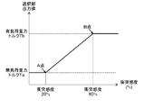
- FIG. 5 is a diagram illustrating the relationship between the collision sensitivity and the set holding torque in the robot.
- FIG. 6 is a diagram showing a conventional motor control device 900.
- FIG. 7 is a diagram showing details of the PI controller 901 of the conventional motor control device 900.
- the conventional motor control apparatus 900 described with reference to FIGS. 6 and 7, the following problem occurs.
- the torque command value T COM stored in the storage unit 907 is the holding torque of the motor 904.
- the torque command value T COM when the brake signal B SIG stored in the storage unit 907 changes from on to off is It is not an appropriate motor 904 holding torque. Therefore, when the motor 904 stops suddenly or stops due to a collision, the conventional motor control device 900 causes the gravitational axis to jump or fall when the motor 904 starts energization, and the arm moves to the peripheral device or workpiece. Risk of collision with workers.
- FIG. 1 is a diagram illustrating a motor control device 21 of the present disclosure. A case where the motor 24 is attached to the robot 100 will be described.
- the encoder 25 detects the position of the rotor of the motor 24 at a predetermined sampling period, and transmits the detected position information D1 of the motor 24 to the conversion unit 26.
- the converter 26 obtains the rotational speed of the rotor of the motor 24 from the time change of the position information D1 transmitted from the encoder 25.
- the rotation speed calculated by the conversion unit 26 is transmitted to the PI controller 22 as a feedback speed VFB. Further, the converter 26 transmits the feedback speed VFB and the position information D1 to the calculator 31.
- Spec information D2 including information about the weight of the tool and the position of the center of gravity of the tool, position information D1 of the motor 24, and feedback speed VFB are input to the calculation unit 31.
- the feedback speed VFB_2 based on the position information of the other motor and the position information D1_2 of the other motor are also calculated from other control blocks.
- the computing unit 31 calculates the gravitational torque TG acting on the motor 24 and transmits the gravitational torque TG to the storage unit 27.
- the PI controller 22 includes a proportional component calculation unit 29 and an integral component calculation unit 30.
- An error speed dV that is a difference between the speed command VCOM and the feedback speed VFB is input to the proportional component calculation unit 29 and the integral component calculation unit 30.
- the integral value VI calculated by the integral component calculation unit 30 is added to the value calculated by the proportional component calculation unit 29 based on the error speed dV, and the torque command value TCOM is supplied from the PI controller 22 to the current control unit 23. Is output.
- the storage unit 27 receives the brake signal BSIG input to the brake device 28, the integral value VI output from the integral component calculation unit 30, and the gravitational torque TG output from the calculation unit 31.
- storage part 27 memorize
- the integral value VI of the torque command value TCOM output from the storage unit 27 and the gravity torque TG are input to the selection unit 32, and the value set by the selection unit 32 is input to the integral component calculation unit 30 of the PI controller 22. Send.
- a value set when the brake signal BSIG changes from on to off is transmitted from the selection unit 32 to the integral component calculation unit 30 of the PI controller 22.
- the torque command value TCOM is input from the PI controller 22 to the current control unit 23.
- the motor control torque TFB is input to the current control unit 23.
- the current control unit 23 calculates a drive command value DCOM and causes a current to flow through the motor 24 based on the drive command value DCOM. Thus, the current control unit 23 controls the driving of the motor 24.
- the collision detection function includes the position information D1 of the motor 24 that can acquire the torque originally acting on the motor 24 from the encoder 25, speed and acceleration information (here, feedback speed VFB), tools, Based on the specification information D2 such as the mass of the robot body, the calculation unit 31 calculates the dynamic torque TD in advance. Then, the collision detection unit 200 compares the collision detection torque TC, which is the difference between the motor generated torque TFB actually applied to the motor 24 by the control from the current control unit 23 and the dynamic torque TD, with the collision detection threshold value Vt. .
- the collision detection threshold Vt is determined according to the collision sensitivity X set in advance.
- the collision detection result R is determined to be a collision.
- the collision sensitivity X can be set by the user, and a threshold width is provided according to the sensitivity to prevent an erroneous detection of the collision and perform an accurate collision detection.
- the collision detection unit 200 when the collision detection torque TC (maximum torque ratio) is 20%, if the collision sensitivity X is set to 20%, 50%, or 80%, it is not detected as “collision”. On the other hand, if the collision sensitivity X is set to 100%, it is detected as “collision”. That is, the collision detection threshold Vt is set to 80% or more and less than 100%.
- the collision detection threshold Vt is set so that the collision sensitivity X is not less than 50% and less than 80%. For example, the collision sensitivity X is set to 50%. If the collision sensitivity X is set to 80%, it is detected as “collision”.
- the collision detection threshold value Vt is set so that the collision sensitivity X is 20% or more and less than 50%. For example, the collision sensitivity X is set to 20%. If the collision sensitivity X is set to 50% or more, “collision” is detected.
- FIG. 4 is an example showing the relationship between the collision sensitivity X and the collision detection torque TC. If the setting of the collision detection threshold Vt is different, the relationship between the collision detection torque TC and the collision sensitivity X is different from that in FIG. If the collision sensitivity is set high, the frequency of collision detection increases, and if the collision sensitivity is set low, the frequency of collision detection decreases.
- collision sensitivity For example, if the collision sensitivity is set high, even a small impact is regarded as “collision”. On the other hand, if the collision sensitivity is set low, it is not regarded as “collision” only by a small impact.
- the size of the collision detection threshold Vt is determined by the set collision sensitivity X. Therefore, it can be said that the set collision sensitivity X represents the accuracy of the load information.
- the collision sensitivity X can be arbitrarily set in advance in the specification information input unit 300 by the user.
- the selection unit 32 receives the integral value VI from the integral component calculation unit 30 and the gravity torque TG from the calculation unit 31 to the storage unit 27 ( S2).
- the integral value VI and the gravitational torque TG are input from the storage unit 27 to the selection unit 32 (S3).
- the selector 32 compares the input integral value VI with the gravitational torque TG (S4). If the difference between the integral value VI and the gravitational torque TG is larger than a certain value (S4 is YES), it is considered that the motor 904 has stopped suddenly or has stopped due to a collision.
- the no-load gravity torque Ta is output to the integral component calculation unit 30 of the PI controller 22 (S5).
- the selector 32 selects the gravitational torque corresponding to the collision sensitivity X output from the spec information input unit 300, as the integral component.
- the result is output to the calculation unit 30 (S6 to S8).
- the gravity torque corresponding to the set sensitivity is applied from the selection unit 32 along the straight line passing through the points A and B to the integration of the PI controller 22. It outputs to the component calculating part 30 (S8).
- the user arbitrarily sets the collision sensitivity X in the specification information input unit 300 in advance. Further, the user sets the load information as the specification information D2 in the specification information input unit 300. And as above-mentioned, according to the collision detection result R of the collision detection part 200, the user can reset the specification information D2.
- the PI controller 22 uses the value input from the selection unit 32 to the integral component calculation unit 30 according to the collision sensitivity X as the holding torque. Therefore, even when the motor 24 is stopped due to a sudden stop or a collision, it is possible to prevent the gravity shaft from jumping up and dropping when the brake signal BSIG changes from OFF to ON again (at the start of energization of the motor). it can.
- the motor control device 21 of the present disclosure includes a PI controller 22, a specification information input unit 300, a calculation unit 31, a storage unit 27, and a selection unit 32.
- the specification information input unit 300 receives specification information D2 including information on the weight of the tool and the position of the center of gravity of the tool.
- the calculation unit 31 calculates the gravitational torque TG based on the specification information D2.
- the storage unit 27 stores the gravitational torque TG output from the calculation unit 31 and the integral value VI output from the PI controller 22. Further, the storage unit 27 outputs the gravity torque TG and the integral value VI in accordance with the brake signal BSIG.
- the selection unit 32 sets the integral value VI input from the storage unit 27 in the PI controller 22 according to the collision sensitivity X input from the specification information input unit 300.
- the selection unit 32 when the specification information D2 includes the load information and it is determined that the tool is not attached based on the load information of the specification information D2, the selection unit 32 generates the no-load gravity torque.
- the integral value VI is set in the PI controller 22.
- the selection unit 32 sets the loaded gravity torque as the integral value VI in the PI controller 22.
- the specification information D2 can be arbitrarily set by the user.
- the motor control device 21 of the present disclosure is industrially useful because it can prevent the gravitational axis from jumping or falling when the motor is energized even when the motor is stopped due to a sudden stop or a collision.
Landscapes
- Engineering & Computer Science (AREA)
- Power Engineering (AREA)
- Robotics (AREA)
- Mechanical Engineering (AREA)
- Control Of Electric Motors In General (AREA)
Abstract
Description
次に、衝突感度について図1および図3を参照しながら説明する。衝突検出機能は図3に示すように、モータ24に本来働くトルクを、エンコーダ25から取得できるモータ24の位置情報D1と、速度、加速度の情報(ここではフィードバック速度VFBとする)と、ツールやロボット本体の質量などのスペック情報D2と、から、演算部31で、あらかじ動力学トルクTDを演算しておく。そして、衝突検出部200で、実際に電流制御部23からの制御によりモータ24に働いたモータ発生トルクTFBと、動力学トルクTDとの差である衝突検出トルクTCを衝突検出閾値Vtと比較する。なお、衝突検出閾値Vtは、事前に設定されている衝突感度Xに応じて決まっている。衝突検出トルクTCが衝突検出閾値Vt以上であれば衝突したとする衝突検出結果Rとなる。また衝突感度Xは、ユーザーによって設定可能であり、感度に応じて閾値の幅を設け、衝突の誤検出を防ぎ正確な衝突検出を行っている。 [Operation of collision detection unit 200]
Next, the collision sensitivity will be described with reference to FIG. 1 and FIG. As shown in FIG. 3, the collision detection function includes the position information D1 of the
次に、図1、図2を用いて、選択部32の動作について、具体的に説明する。選択部32はブレーキ信号BSIGがオンからオフに変化した時(S1)、記憶部27には、積分成分演算部30から積分値VIが入力され、演算部31から重力トルクTGが入力される(S2)。次に、記憶部27から選択部32に、積分値VIおよび重力トルクTGが入力される(S3)。選択部32では入力された積分値VIと重力トルクTGを比較する(S4)。積分値VIと重力トルクTGの差が一定の値より大きければ(S4がYES)、モータ904が急停止した、または、衝突によって停止した、と考えられる。この時、無負荷重力トルクTaをPI制御器22の積分成分演算部30へと出力する(S5)。 [Description of the operation of the selection unit 32]
Next, the operation of the
本開示のモータ制御装置21は、PI制御器22と、スペック情報入力部300と、演算部31と、記憶部27と、選択部32と、を有する。 (Summary)
The
22 PI制御器
23 電流制御部
24 モータ
25 エンコーダ
26 変換部
27 記憶部
28 ブレーキ装置
29 比例成分演算部
30 積分成分演算部
31 演算部
32 選択部
100 ロボット
200 衝突検出部
300 スペック情報入力部
900 モータ制御装置
901 PI制御器
902 電流制御部
903 インバータ回路
904 モータ
905 エンコーダ
906 変換部
907 記憶部
908 ブレーキ装置
911 比例成分演算部
912 積分成分演算部
dV 誤差速度
BSIG ブレーキ信号
D1 位置情報
D2 スペック情報
DCOM 駆動指令値
Ta 無負荷重力トルク
Tb 有負荷重力トルク
TC 衝突検出トルク
TD 動力学トルク
TG 重力トルク
TFB モータ発生トルク
TCOM トルク指令値
R 衝突検出結果
VCOM 速度指令
VFB フィードバック速度
IFB フィードバック電流
X 衝突感度
Vt 衝突検出閾値
VI 積分値 21
Claims (3)
- モータの速度を制御するPI制御器と、
ツールの重量および前記ツールの重心位置の情報を含むスペック情報が入力される入力部と、
前記スペック情報に基づいて重力トルクを算出する演算部と、
前記演算部から出力される前記重力トルク、および、前記PI制御部から出力される積分値を記憶し、かつ、ブレーキ信号に応じて前記重力トルク及び前記積分値を出力する記憶部と、
前記記憶部から出力される前記積分値を前記入力部から入力される衝突感度に応じて前記PI制御器に設定する選択部と、
を備えたモータ制御装置。 A PI controller for controlling the speed of the motor;
An input unit for inputting spec information including information on the weight of the tool and the center of gravity of the tool;
A calculation unit for calculating a gravitational torque based on the spec information;
A storage unit that stores the gravitational torque output from the arithmetic unit and the integrated value output from the PI control unit, and outputs the gravitational torque and the integrated value in response to a brake signal;
A selection unit that sets the integral value output from the storage unit in the PI controller according to a collision sensitivity input from the input unit;
A motor control device comprising: - 前記スペック情報が負荷情報を含み、
前記スペック情報の前記負荷情報に基づいて前記ツールが取り付けられていないと判断された場合、前記選択部は無負荷重力トルクを前記積分値として前記PI制御器に設定し、
前記スペック情報の前記負荷情報に基づいて前記ツールが取り付けられていると判断された場合、前記選択部は有負荷重力トルクを前記積分値として前記PI制御器に設定する、請求項1記載のモータ制御装置。 The spec information includes load information,
When it is determined that the tool is not attached based on the load information of the spec information, the selection unit sets no-load gravity torque as the integral value in the PI controller,
2. The motor according to claim 1, wherein when it is determined that the tool is attached based on the load information of the spec information, the selection unit sets a loaded gravity torque as the integral value in the PI controller. Control device. - 前記スペック情報は任意に設定できる請求項1または2記載のモータ制御装置。 The motor control device according to claim 1 or 2, wherein the specification information can be arbitrarily set.
Priority Applications (4)
| Application Number | Priority Date | Filing Date | Title |
|---|---|---|---|
| US16/071,113 US10644619B2 (en) | 2016-03-29 | 2017-03-27 | Motor control device |
| CN201780009217.0A CN108604878B (en) | 2016-03-29 | 2017-03-27 | Motor control device |
| EP17774854.8A EP3439168B1 (en) | 2016-03-29 | 2017-03-27 | Motor control device |
| JP2018509298A JP6731583B2 (en) | 2016-03-29 | 2017-03-27 | Motor controller |
Applications Claiming Priority (2)
| Application Number | Priority Date | Filing Date | Title |
|---|---|---|---|
| JP2016065317 | 2016-03-29 | ||
| JP2016-065317 | 2016-03-29 |
Publications (1)
| Publication Number | Publication Date |
|---|---|
| WO2017170317A1 true WO2017170317A1 (en) | 2017-10-05 |
Family
ID=59965458
Family Applications (1)
| Application Number | Title | Priority Date | Filing Date |
|---|---|---|---|
| PCT/JP2017/012233 WO2017170317A1 (en) | 2016-03-29 | 2017-03-27 | Motor control device |
Country Status (5)
| Country | Link |
|---|---|
| US (1) | US10644619B2 (en) |
| EP (1) | EP3439168B1 (en) |
| JP (1) | JP6731583B2 (en) |
| CN (1) | CN108604878B (en) |
| WO (1) | WO2017170317A1 (en) |
Cited By (2)
| Publication number | Priority date | Publication date | Assignee | Title |
|---|---|---|---|---|
| CN110000815A (en) * | 2019-04-09 | 2019-07-12 | 深圳前海达闼云端智能科技有限公司 | Collision detection method and device, electronic equipment and storage medium |
| CN112041125A (en) * | 2018-05-10 | 2020-12-04 | 松下知识产权经营株式会社 | Robot control method |
Families Citing this family (3)
| Publication number | Priority date | Publication date | Assignee | Title |
|---|---|---|---|---|
| EP4052864A4 (en) * | 2019-10-30 | 2023-11-22 | Neuromeka | Method for automatically setting collision sensitivity of collaborative robot |
| CN113037141A (en) * | 2021-03-10 | 2021-06-25 | 深圳市微秒控制技术有限公司 | Anti-falling method for gravity load starting of servo motor |
| CN114505863B (en) * | 2022-03-09 | 2024-01-26 | 国汽朴津智能科技(合肥)有限公司 | Rotational speed control method and device for intelligent robot |
Citations (6)
| Publication number | Priority date | Publication date | Assignee | Title |
|---|---|---|---|---|
| US4858053A (en) * | 1985-11-01 | 1989-08-15 | Square D Company | Operational amplifier having an improved feedback system including an integrator having a hurry-up circuit, and an electric motor control using the same for inverse trip selection |
| JPH07322666A (en) * | 1994-05-23 | 1995-12-08 | Hitachi Ltd | Controller for variable speed drive system |
| JP2000501280A (en) * | 1996-09-16 | 2000-02-02 | ローベルト ボツシユ ゲゼルシヤフト ミツト ベシユレンクテル ハフツング | Device for identification of pinching situation in electric drive mechanism |
| JP2000333488A (en) * | 1999-05-18 | 2000-11-30 | Denso Corp | Dc motor drive and motor-driven power steering controller |
| CN103273852A (en) * | 2013-04-25 | 2013-09-04 | 华南农业大学 | Electric field carrier distribution type driving system and control method thereof |
| CN103312241A (en) * | 2013-06-08 | 2013-09-18 | 西北工业大学 | Optimization and restart control method for use in outage of large-inertial-load permanent magnet synchronous motor |
Family Cites Families (10)
| Publication number | Priority date | Publication date | Assignee | Title |
|---|---|---|---|---|
| JPS638912A (en) | 1986-06-30 | 1988-01-14 | Fanuc Ltd | Control system for robot |
| KR100439466B1 (en) * | 1995-09-11 | 2004-09-18 | 가부시키가이샤 야스가와덴끼 | Robot controller |
| JP4323351B2 (en) * | 2004-03-12 | 2009-09-02 | 川崎重工業株式会社 | Braking performance detection method and braking performance detection device |
| JP5189926B2 (en) | 2008-08-12 | 2013-04-24 | オークマ株式会社 | Motor control device |
| JP2010074915A (en) * | 2008-09-17 | 2010-04-02 | Jtekt Corp | Motor controller and electric power steering device |
| CN102378703B (en) * | 2009-03-31 | 2014-04-16 | 爱考斯研究株式会社 | Vehicle |
| JP4676551B1 (en) * | 2009-12-22 | 2011-04-27 | ファナック株式会社 | Motor control device having cogging torque correction amount calculation function |
| CN103025492B (en) | 2010-12-08 | 2015-07-22 | 松下电器产业株式会社 | Control device and control method for robot, and robot |
| JP5360254B2 (en) * | 2012-03-21 | 2013-12-04 | トヨタ自動車株式会社 | Torque detection method and arm device |
| JP2013226619A (en) | 2012-04-25 | 2013-11-07 | Jtekt Corp | Robot control method and robot control device |
-
2017
- 2017-03-27 US US16/071,113 patent/US10644619B2/en active Active
- 2017-03-27 CN CN201780009217.0A patent/CN108604878B/en active Active
- 2017-03-27 EP EP17774854.8A patent/EP3439168B1/en active Active
- 2017-03-27 JP JP2018509298A patent/JP6731583B2/en active Active
- 2017-03-27 WO PCT/JP2017/012233 patent/WO2017170317A1/en active Application Filing
Patent Citations (6)
| Publication number | Priority date | Publication date | Assignee | Title |
|---|---|---|---|---|
| US4858053A (en) * | 1985-11-01 | 1989-08-15 | Square D Company | Operational amplifier having an improved feedback system including an integrator having a hurry-up circuit, and an electric motor control using the same for inverse trip selection |
| JPH07322666A (en) * | 1994-05-23 | 1995-12-08 | Hitachi Ltd | Controller for variable speed drive system |
| JP2000501280A (en) * | 1996-09-16 | 2000-02-02 | ローベルト ボツシユ ゲゼルシヤフト ミツト ベシユレンクテル ハフツング | Device for identification of pinching situation in electric drive mechanism |
| JP2000333488A (en) * | 1999-05-18 | 2000-11-30 | Denso Corp | Dc motor drive and motor-driven power steering controller |
| CN103273852A (en) * | 2013-04-25 | 2013-09-04 | 华南农业大学 | Electric field carrier distribution type driving system and control method thereof |
| CN103312241A (en) * | 2013-06-08 | 2013-09-18 | 西北工业大学 | Optimization and restart control method for use in outage of large-inertial-load permanent magnet synchronous motor |
Non-Patent Citations (1)
| Title |
|---|
| See also references of EP3439168A4 * |
Cited By (7)
| Publication number | Priority date | Publication date | Assignee | Title |
|---|---|---|---|---|
| CN112041125A (en) * | 2018-05-10 | 2020-12-04 | 松下知识产权经营株式会社 | Robot control method |
| JPWO2019215998A1 (en) * | 2018-05-10 | 2021-05-20 | パナソニックIpマネジメント株式会社 | Robot control method |
| EP3792011A4 (en) * | 2018-05-10 | 2021-07-07 | Panasonic Intellectual Property Management Co., Ltd. | Robot control method |
| JP7165951B2 (en) | 2018-05-10 | 2022-11-07 | パナソニックIpマネジメント株式会社 | Robot control method |
| CN112041125B (en) * | 2018-05-10 | 2023-11-24 | 松下知识产权经营株式会社 | Robot control method |
| US11890759B2 (en) | 2018-05-10 | 2024-02-06 | Panasonic Intellectual Property Management Co., Ltd. | Robot control method |
| CN110000815A (en) * | 2019-04-09 | 2019-07-12 | 深圳前海达闼云端智能科技有限公司 | Collision detection method and device, electronic equipment and storage medium |
Also Published As
| Publication number | Publication date |
|---|---|
| CN108604878A (en) | 2018-09-28 |
| EP3439168A4 (en) | 2019-03-13 |
| JPWO2017170317A1 (en) | 2019-02-14 |
| JP6731583B2 (en) | 2020-07-29 |
| EP3439168B1 (en) | 2022-02-23 |
| CN108604878B (en) | 2021-09-28 |
| US10644619B2 (en) | 2020-05-05 |
| US20190260313A1 (en) | 2019-08-22 |
| EP3439168A1 (en) | 2019-02-06 |
Similar Documents
| Publication | Publication Date | Title |
|---|---|---|
| WO2017170317A1 (en) | Motor control device | |
| JP5024383B2 (en) | Robot abnormality determination method | |
| JP5015816B2 (en) | Tailstock controller | |
| US20060129348A1 (en) | System for collision a voidance of rotary atomizer | |
| JP2016087700A (en) | Control equipment having feature of verifying designation of load information | |
| JP2012039847A (en) | Motor controller and motor control method | |
| US20220226995A1 (en) | Control of a multipurpose robot arm | |
| WO1993008958A1 (en) | Abnormal load detecting method | |
| CN109085802B (en) | Control device for motor | |
| US10031507B2 (en) | Servo control device | |
| JP2013169609A (en) | Method for detecting collision of robot | |
| JP4453526B2 (en) | Servo control device | |
| JP2006123012A (en) | Robot control method | |
| JP3933158B2 (en) | Robot collision detection method | |
| US20080001567A1 (en) | Motor control device | |
| JP5929150B2 (en) | Robot device | |
| JPH1170490A (en) | Collision detecting method for industrial robot | |
| JP2004364396A (en) | Controller and control method for motor | |
| CN107894749B (en) | Servo motor control device, servo motor control method, and computer-readable recording medium | |
| JP5151994B2 (en) | Moment of inertia identification device, identification method thereof, and motor control device including the identification device | |
| JP5620452B2 (en) | Motor control device for controlling a plurality of motors for driving one driven body | |
| JP4807260B2 (en) | Motor control device and control method thereof | |
| EP3678290B1 (en) | Motor driving device | |
| JP3771110B2 (en) | Control device and control method for mechanical system | |
| US10599136B2 (en) | Motor controller and method for controlling motor |
Legal Events
| Date | Code | Title | Description |
|---|---|---|---|
| WWE | Wipo information: entry into national phase |
Ref document number: 2018509298 Country of ref document: JP |
|
| NENP | Non-entry into the national phase |
Ref country code: DE |
|
| WWE | Wipo information: entry into national phase |
Ref document number: 2017774854 Country of ref document: EP |
|
| ENP | Entry into the national phase |
Ref document number: 2017774854 Country of ref document: EP Effective date: 20181029 |
|
| 121 | Ep: the epo has been informed by wipo that ep was designated in this application |
Ref document number: 17774854 Country of ref document: EP Kind code of ref document: A1 |