EP3439168A1 - Motor control device - Google Patents
Motor control device Download PDFInfo
- Publication number
- EP3439168A1 EP3439168A1 EP17774854.8A EP17774854A EP3439168A1 EP 3439168 A1 EP3439168 A1 EP 3439168A1 EP 17774854 A EP17774854 A EP 17774854A EP 3439168 A1 EP3439168 A1 EP 3439168A1
- Authority
- EP
- European Patent Office
- Prior art keywords
- controller
- collision
- torque
- motor
- calculation unit
- Prior art date
- Legal status (The legal status is an assumption and is not a legal conclusion. Google has not performed a legal analysis and makes no representation as to the accuracy of the status listed.)
- Granted
Links
- 230000035945 sensitivity Effects 0.000 claims abstract description 39
- 238000001514 detection method Methods 0.000 description 28
- 230000005484 gravity Effects 0.000 description 7
- 238000005070 sampling Methods 0.000 description 2
- 230000001133 acceleration Effects 0.000 description 1
- 230000007423 decrease Effects 0.000 description 1
- 230000010354 integration Effects 0.000 description 1
- 238000000034 method Methods 0.000 description 1
- 230000002093 peripheral effect Effects 0.000 description 1
- 230000002123 temporal effect Effects 0.000 description 1
Images


Classifications
-
- H—ELECTRICITY
- H02—GENERATION; CONVERSION OR DISTRIBUTION OF ELECTRIC POWER
- H02P—CONTROL OR REGULATION OF ELECTRIC MOTORS, ELECTRIC GENERATORS OR DYNAMO-ELECTRIC CONVERTERS; CONTROLLING TRANSFORMERS, REACTORS OR CHOKE COILS
- H02P1/00—Arrangements for starting electric motors or dynamo-electric converters
- H02P1/02—Details of starting control
- H02P1/029—Restarting, e.g. after power failure
-
- B—PERFORMING OPERATIONS; TRANSPORTING
- B25—HAND TOOLS; PORTABLE POWER-DRIVEN TOOLS; MANIPULATORS
- B25J—MANIPULATORS; CHAMBERS PROVIDED WITH MANIPULATION DEVICES
- B25J9/00—Programme-controlled manipulators
- B25J9/16—Programme controls
- B25J9/1628—Programme controls characterised by the control loop
- B25J9/1638—Programme controls characterised by the control loop compensation for arm bending/inertia, pay load weight/inertia
-
- B—PERFORMING OPERATIONS; TRANSPORTING
- B25—HAND TOOLS; PORTABLE POWER-DRIVEN TOOLS; MANIPULATORS
- B25J—MANIPULATORS; CHAMBERS PROVIDED WITH MANIPULATION DEVICES
- B25J9/00—Programme-controlled manipulators
- B25J9/16—Programme controls
- B25J9/1674—Programme controls characterised by safety, monitoring, diagnostic
- B25J9/1676—Avoiding collision or forbidden zones
-
- H—ELECTRICITY
- H02—GENERATION; CONVERSION OR DISTRIBUTION OF ELECTRIC POWER
- H02P—CONTROL OR REGULATION OF ELECTRIC MOTORS, ELECTRIC GENERATORS OR DYNAMO-ELECTRIC CONVERTERS; CONTROLLING TRANSFORMERS, REACTORS OR CHOKE COILS
- H02P23/00—Arrangements or methods for the control of AC motors characterised by a control method other than vector control
- H02P23/0004—Control strategies in general, e.g. linear type, e.g. P, PI, PID, using robust control
-
- H—ELECTRICITY
- H02—GENERATION; CONVERSION OR DISTRIBUTION OF ELECTRIC POWER
- H02P—CONTROL OR REGULATION OF ELECTRIC MOTORS, ELECTRIC GENERATORS OR DYNAMO-ELECTRIC CONVERTERS; CONTROLLING TRANSFORMERS, REACTORS OR CHOKE COILS
- H02P23/00—Arrangements or methods for the control of AC motors characterised by a control method other than vector control
- H02P23/14—Estimation or adaptation of motor parameters, e.g. rotor time constant, flux, speed, current or voltage
-
- H—ELECTRICITY
- H02—GENERATION; CONVERSION OR DISTRIBUTION OF ELECTRIC POWER
- H02P—CONTROL OR REGULATION OF ELECTRIC MOTORS, ELECTRIC GENERATORS OR DYNAMO-ELECTRIC CONVERTERS; CONTROLLING TRANSFORMERS, REACTORS OR CHOKE COILS
- H02P23/00—Arrangements or methods for the control of AC motors characterised by a control method other than vector control
- H02P23/16—Controlling the angular speed of one shaft
-
- H—ELECTRICITY
- H02—GENERATION; CONVERSION OR DISTRIBUTION OF ELECTRIC POWER
- H02P—CONTROL OR REGULATION OF ELECTRIC MOTORS, ELECTRIC GENERATORS OR DYNAMO-ELECTRIC CONVERTERS; CONTROLLING TRANSFORMERS, REACTORS OR CHOKE COILS
- H02P29/00—Arrangements for regulating or controlling electric motors, appropriate for both AC and DC motors
- H02P29/04—Arrangements for regulating or controlling electric motors, appropriate for both AC and DC motors by means of a separate brake
-
- H—ELECTRICITY
- H02—GENERATION; CONVERSION OR DISTRIBUTION OF ELECTRIC POWER
- H02P—CONTROL OR REGULATION OF ELECTRIC MOTORS, ELECTRIC GENERATORS OR DYNAMO-ELECTRIC CONVERTERS; CONTROLLING TRANSFORMERS, REACTORS OR CHOKE COILS
- H02P29/00—Arrangements for regulating or controlling electric motors, appropriate for both AC and DC motors
- H02P29/40—Regulating or controlling the amount of current drawn or delivered by the motor for controlling the mechanical load
-
- G—PHYSICS
- G05—CONTROLLING; REGULATING
- G05B—CONTROL OR REGULATING SYSTEMS IN GENERAL; FUNCTIONAL ELEMENTS OF SUCH SYSTEMS; MONITORING OR TESTING ARRANGEMENTS FOR SUCH SYSTEMS OR ELEMENTS
- G05B19/00—Programme-control systems
- G05B19/02—Programme-control systems electric
- G05B19/18—Numerical control [NC], i.e. automatically operating machines, in particular machine tools, e.g. in a manufacturing environment, so as to execute positioning, movement or co-ordinated operations by means of programme data in numerical form
- G05B19/406—Numerical control [NC], i.e. automatically operating machines, in particular machine tools, e.g. in a manufacturing environment, so as to execute positioning, movement or co-ordinated operations by means of programme data in numerical form characterised by monitoring or safety
- G05B19/4067—Restoring data or position after power failure or other interruption
-
- G—PHYSICS
- G05—CONTROLLING; REGULATING
- G05B—CONTROL OR REGULATING SYSTEMS IN GENERAL; FUNCTIONAL ELEMENTS OF SUCH SYSTEMS; MONITORING OR TESTING ARRANGEMENTS FOR SUCH SYSTEMS OR ELEMENTS
- G05B19/00—Programme-control systems
- G05B19/02—Programme-control systems electric
- G05B19/18—Numerical control [NC], i.e. automatically operating machines, in particular machine tools, e.g. in a manufacturing environment, so as to execute positioning, movement or co-ordinated operations by means of programme data in numerical form
- G05B19/4093—Numerical control [NC], i.e. automatically operating machines, in particular machine tools, e.g. in a manufacturing environment, so as to execute positioning, movement or co-ordinated operations by means of programme data in numerical form characterised by part programming, e.g. entry of geometrical information as taken from a technical drawing, combining this with machining and material information to obtain control information, named part programme, for the NC machine
- G05B19/40937—Numerical control [NC], i.e. automatically operating machines, in particular machine tools, e.g. in a manufacturing environment, so as to execute positioning, movement or co-ordinated operations by means of programme data in numerical form characterised by part programming, e.g. entry of geometrical information as taken from a technical drawing, combining this with machining and material information to obtain control information, named part programme, for the NC machine concerning programming of machining or material parameters, pocket machining
- G05B19/40938—Tool management
-
- G—PHYSICS
- G05—CONTROLLING; REGULATING
- G05B—CONTROL OR REGULATING SYSTEMS IN GENERAL; FUNCTIONAL ELEMENTS OF SUCH SYSTEMS; MONITORING OR TESTING ARRANGEMENTS FOR SUCH SYSTEMS OR ELEMENTS
- G05B2219/00—Program-control systems
- G05B2219/30—Nc systems
- G05B2219/50—Machine tool, machine tool null till machine tool work handling
- G05B2219/50391—Robot
-
- H—ELECTRICITY
- H02—GENERATION; CONVERSION OR DISTRIBUTION OF ELECTRIC POWER
- H02P—CONTROL OR REGULATION OF ELECTRIC MOTORS, ELECTRIC GENERATORS OR DYNAMO-ELECTRIC CONVERTERS; CONTROLLING TRANSFORMERS, REACTORS OR CHOKE COILS
- H02P2205/00—Indexing scheme relating to controlling arrangements characterised by the control loops
- H02P2205/07—Speed loop, i.e. comparison of the motor speed with a speed reference
Definitions
- the present disclosure relates to a motor control device, and, in particular, to the correction of the gravitational torque of the motor at the time of re-operation after stopping.
- a motor control device which stabilizes the behavior of the gravity shaft in a robot such as a manipulator to prevent the gravity shaft from falling when power is supplied to the servomotor which drives the gravity shaft.
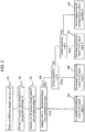
- FIG. 6 illustrates conventional motor control device 900.
- FIG. 7 illustrates the details of proportional-integral (PI) controller 901 of conventional motor control device 900.
- PI proportional-integral
- conventional motor control device 900 includes PI controller 901, current controller 902, inverter circuit 903, motor 904, encoder 905, converter 906, storage 907, and breaking device 908.
- Encoder 905 detects the position of the rotor of motor 904 at a predetermined sampling period, and transmits the detected positional information to converter 906.
- Converter 906 calculates the rotational velocity of the rotor of motor 904 from the change in position of the rotor based on the positional information transmitted from encoder 905.
- Converter 906 then transmits, to PI controller 901, the calculated rotational velocity of the rotor as feedback velocity V FB .
- Storage 907 receives break signal B SIG to be input to breaking device 908, and torque command value T COM output from PI controller 901, and stores torque command value T COM . Moreover, when break signal B SIG is changed from ON to OFF, storage 907 outputs torque command value T COM at that time to PI controller 901.
- PI controller 901 receives velocity command V COM and feedback velocity V FB . PI controller 901 performs calculation to output torque command value T COM to current controller 902. Moreover, PI controller 901 receives, from storage 907, torque command value T COM obtained when brake signal B SIG is changed from ON to OFF.
- Current controller 902 receives torque command value T COM and feedback current I FB of the current to be supplied to motor 904, calculates an inverter drive command, and outputs the calculated inverter drive command to inverter circuit 903.
- Inverter circuit 903 supplies current to motor 904 based on the received inverter drive command to control the driving of motor 904.
- PI controller 901 includes proportional component calculation unit 911 and integral component calculation unit 912.
- Proportional component calculation unit 911 and integral component calculation unit 912 each receive error velocity dV which is the difference between velocity command V COM and feedback velocity V FB .
- the value calculated by proportional component calculation unit 911 from error velocity dV and the value calculated by integral component calculation unit 912 from error velocity dV are added, and torque command value T COM is output.
- the output torque command value T COM is stored in storage 907. Subsequently, as described above, torque command value T COM obtained when brake signal B SIG is changed from ON to OFF is output from storage 907 to integral component calculation unit 912 of PI controller 901.
- PI controller 901 uses torque command value T COM obtained when brake signal B SIG is changed from ON to OFF as a holding torque, so that the falling of the gravity shaft can be prevented when brake signal B SIG is changed again from OFF to ON (when power starts to be supplied to motor 904) (for example, see Patent Literature (PTL) 1).
- a motor control device includes: a PI controller which controls the velocity of a motor; an input unit which receives specification information including information of the weight and the center of mass of a tool; a calculation unit which calculates a gravitational torque based on the specification information; a storage which stores an integral value output from the PI controller and outputs the gravitational torque and the integral value in response to a break signal, and a selection unit which sets, to the PI controller, the integral value output from the storage, according to a collision sensitivity input from the input unit.
- Conventional motor control device 900 which has been described with reference to FIG. 6 and FIG. 7 has the following problem.
- torque command value T COM stored in storage 907 is the holding torque of motor 904.
- torque command value T COM obtained when brake signal B SIG stored in storage 907 is changed from ON to OFF is not an appropriate holding torque of motor 904 at such a time. Therefore, when motor 904 has stopped suddenly or when motor 904 has been stopped by a collision in conventional motor control device 900, the gravity shaft bounces or falls when power starts to be supplied to motor 904, which poses a risk that the arm collides with peripheral devices or workers.
- FIG. 1 illustrates motor control device 21 according to the present disclosure. The case where motor 24 has been attached to robot 100 will be described.
- Encoder 25 detects the position of the rotor of motor 24 at a predetermined sampling period, and transmits detected positional information D1 of motor 24 to converter 26.
- Converter 26 calculates the rotational velocity of the rotor of motor 24 from the temporal change in positional information D1 transmitted from encoder 25. The rotational velocity calculated by converter 26 is transmitted as feedback velocity VFB to PI controller 22. Moreover, converter 26 transmits feedback velocity VFB and positional information D1 to calculation unit 31.
- Calculation unit 31 receives: specification information D2 including information of the weight and the center of mass of a tool; positional information D1 of motor 24; and feedback velocity VFB. Moreover, when robot 100 includes another motor (not illustrated) in addition to motor 24, feedback velocity VFB_2 based on the positional information of the other motor and positional information D1_2 of the other motor are also input to calculation unit 31 from another control block. Calculation unit 31 calculates gravitational torque TG which acts on motor 24, and transmits gravitational torque TG to storage 27.
- PI controller 22 includes proportional component calculation unit 29 and integral component calculation unit 30.
- Proportional component calculation unit 29 and integral component calculation unit 30 each receive error velocity dV which is the difference between velocity command VCOM and feedback velocity VFB.
- Integral value VI calculated by integral component calculation unit 30 is added to the value calculated by proportional component calculation unit 29 based on error velocity dV, so that torque command value TCOM is output from PI controller 22 to current controller 23.
- Storage 27 receives break signal BSIG to be input to breaking device 28, integral value VI output from integral component calculation unit 30, and gravitational torque TG output from calculation unit 31.
- Storage 27 then stores integrated value VI output from integral component calculation unit 30 and gravitational torque TG.
- Storage 27 transmits, to selection unit 32, integral value VI and gravitational torque TG obtained when brake signal BSIG is changed from ON to OFF.
- Selection unit 32 receives integral value VI of torque command value TCOM and gravitational torque TG output from storage 27, and transmits the value set by selection unit 32 to integral component calculation unit 30 of PI controller 22.
- the value set when brake signal BSIG is changed from ON to OFF is transmitted from selection unit 32 to integral component calculation unit 30 of PI controller 22.
- Current controller 23 receives torque command value TCOM from PI controller 22. Moreover, current controller 23 receives motor-generated torque TFB. Current controller 23 calculates drive command value DCOM, and supplies current to motor 24 based on drive command value DCOM. In such a manner, current controller 23 controls the driving of motor 24.
- collision detection function calculates, in advance, the torque which originally acts on motor 24 as dynamic torque TD from positional information D1 of motor 24 that can be obtained from encoder 25, information of the velocity and acceleration (here, feedback velocity VFB), and specification information D2 such as the mass of the tool and the robot body.
- Collision detector 200 compares, with collision detection threshold Vt, collision detection torque TC which is the difference between motor-generated torque TFB which has actually acted on motor 24 under the control of current controller 23 and dynamic torque TD. Note that collision detection threshold Vt is determined according to collision sensitivity X set in advance.
- collision detection result R indicates that a collision has occurred.
- collision sensitivity X can be set by a user. The range of the threshold is set according to the sensitivity, so that a collision is correctly detected while preventing a false detection of a collision.
- collision detection threshold Vt is set to a value in a range from greater than or equal to 80% to less than 100% of collision sensitivity X.
- collision detection torque TC maximum torque ratio
- an operation is performed in a similar manner to the operation performed when collision detection torque TC is 20%.
- collision detection threshold Vt is set to a value in a range from greater than or equal to 50% to less than 80% of collision sensitivity X.
- collision detection torque TC maximum torque ratio
- collision detection threshold Vt is set to a value in a range from greater than or equal to 50% to less than 80% of collision sensitivity X.
- collision detection threshold Vt is set to a value in a range from greater than or equal to 20% to less than 50% of collision sensitivity X.
- collision detection torque TC maximum torque ratio
- collision detection threshold Vt is set to a value in a range from greater than or equal to 20% to less than 50% of collision sensitivity X.
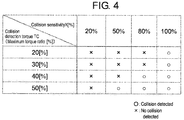
- FIG. 4 illustrates an example of a relationship between collision sensitivity X and collision detection torque TC. Note that when collision detection threshold Vt is set differently, the relationship between collision detection torque TC and collision sensitivity X is different from FIG. 4 . When the collision sensitivity is set to be higher, the frequency of the detection of a collision increases, and when the collision sensitivity is set to be lower, the frequency of the detection of a collision decreases.
- collision sensitivity when the collision sensitivity is set to be higher, even if a small impact is made, a "collision" is detected. In contrast, when the collision sensitivity is set to be lower, a small impact is not considered as a "collision".
- collision sensitivity X when a collision torque is detected when power starts to be supplied to motor 24, the magnitude of collision detection threshold Vt is determined according to collision sensitivity X which has been set. Accordingly, it can be said that collision sensitivity X which has been set indicates the accuracy of load information. Note that collision sensitivity X can be arbitrarily set to specification information input unit 300 by a user in advance.
- selection unit 32 when break signal BSIG is changed from ON to OFF (S1), storage 27 receives integral value VI from integral component calculation unit 30 and gravitational torque TG from calculation unit 31 (S2). Next, integral value VI and gravitational torque TG are input to selection unit 32 from storage 27 (S3). Selection unit 32 compares integration value VI and gravitational torque TG which have been input (S4). When the difference between integral value VI and gravitational torque TG is greater than a predetermined value (YES in S4), it is considered that motor 904 has stopped suddenly or motor 904 has been stopped by a collision. Here, an unloaded gravitational torque Ta is output to integral component calculation unit 30 of PI controller 22 (S5).
- selection unit 32 outputs, to integral component calculation unit 30, the gravitational torque corresponding to collision sensitivity X output from specification information input unit 300 (S6 to S8).
- selection unit 32 When collision sensitivity X is less than 20%, selection unit 32 outputs unloaded gravitational torque Ta to integral component calculation unit 30 of PI controller 22 (S6). When collision sensitivity X is greater than 80%, selection unit 32 outputs loaded gravitational torque Tb to integral component calculation unit 30 of PI controller 22 (S7). When collision sensitivity X is greater than or equal to 20% and less than or equal to 80%, as illustrated in FIG. 5 , loaded gravitational torque Tb is output when collision sensitivity X is 80% and unloaded gravitational torque Ta is output when collision sensitivity X is 20%.
- selection unit 32 When collision sensitivity X is greater than or equal to 20% and less than or equal to 80%, selection unit 32 outputs, to integral component calculation unit 30 of PI controller 22, the gravitational torque corresponding to the set sensitivity along the straight line passing through points A and B (S8).
- the user arbitrarily sets collision sensitivity X in advance to specification information input unit 300. Moreover, the user sets load information as specification information D2 in advance to specification information input unit 300. Subsequently, as described above, the user can reset specification information D2 according to collision detection result R of collision detector 200.
- PI controller 22 uses, as a holding torque, the value input by selection unit 32 to integral component calculation unit 30 according to collision sensitivity X. Therefore, even when motor 24 has stopped suddenly or has been stopped by a collision, it is possible to prevent the gravity shaft from bouncing or falling when break signal BSIG is changed from OFF to ON again (when power starts to be supplied to the motor).
- Motor control device 21 includes PI controller 22, specification information input unit 300, calculation unit 31, storage 27, and selection unit 32.
- Specification information input unit 300 receives specification information D2 including information of the weight and the center of mass of the tool.
- Calculation unit 31 calculates gravitational torque TG based on specification information D2.
- Storage 27 stores gravitational torque TG output from calculation unit 31 and integral value VI output from PI controller 22. Storage 27 further outputs gravitational torque TG and integral value VI in response to break signal BSIG.
- Selection unit 32 sets, to PI controller 22, integral value VI input from storage unit 27, according to collision sensitivity X input from specification information input unit 300.
- specification information D2 includes load information, and when it is determined based on the load information of specification information D2 that no tool has been attached, selection unit 32 sets, to PI controller 22, unloaded gravitational torque as integral value VI. When it is determined based on the load information of specification information D2 that a tool has been attached, selection unit 32 sets, to PI controller 22, loaded gravitational torque as integral value VI.
- specification information D2 can be arbitrarily set by a user.
- Motor control device 21 according to the present disclosure can prevent the gravity shaft from bouncing or falling when power starts to be supplied to the motor, even when the motor has stopped suddenly or the motor has been stopped by a collision. Hence, motor control device 21 according to the present disclosure is industrially useful.
Landscapes
- Engineering & Computer Science (AREA)
- Power Engineering (AREA)
- Robotics (AREA)
- Mechanical Engineering (AREA)
- Control Of Electric Motors In General (AREA)
Abstract
Description
- The present disclosure relates to a motor control device, and, in particular, to the correction of the gravitational torque of the motor at the time of re-operation after stopping.
- Conventionally, a motor control device has been developed which stabilizes the behavior of the gravity shaft in a robot such as a manipulator to prevent the gravity shaft from falling when power is supplied to the servomotor which drives the gravity shaft.
- Conventional
motor control device 900 will be described with reference toFIG. 6 andFIG. 7 .FIG. 6 illustrates conventionalmotor control device 900.FIG. 7 illustrates the details of proportional-integral (PI)controller 901 of conventionalmotor control device 900. - As illustrated in
FIG. 6 , conventionalmotor control device 900 includesPI controller 901,current controller 902,inverter circuit 903,motor 904,encoder 905,converter 906,storage 907, andbreaking device 908.Encoder 905 detects the position of the rotor ofmotor 904 at a predetermined sampling period, and transmits the detected positional information to converter 906.Converter 906 calculates the rotational velocity of the rotor ofmotor 904 from the change in position of the rotor based on the positional information transmitted fromencoder 905.Converter 906 then transmits, toPI controller 901, the calculated rotational velocity of the rotor as feedback velocity VFB. -
Storage 907 receives break signal BSIG to be input to breakingdevice 908, and torque command value TCOM output fromPI controller 901, and stores torque command value TCOM. Moreover, when break signal BSIG is changed from ON to OFF,storage 907 outputs torque command value TCOM at that time toPI controller 901. -
PI controller 901 receives velocity command VCOM and feedback velocity VFB. PI controller 901 performs calculation to output torque command value TCOM tocurrent controller 902. Moreover,PI controller 901 receives, fromstorage 907, torque command value TCOM obtained when brake signal BSIG is changed from ON to OFF. -
Current controller 902 receives torque command value TCOM and feedback current IFB of the current to be supplied tomotor 904, calculates an inverter drive command, and outputs the calculated inverter drive command to invertercircuit 903.Inverter circuit 903 supplies current tomotor 904 based on the received inverter drive command to control the driving ofmotor 904. - Next, with reference to
FIG. 7 ,PI controller 901 will be specifically described.PI controller 901 includes proportionalcomponent calculation unit 911 and integralcomponent calculation unit 912. Proportionalcomponent calculation unit 911 and integralcomponent calculation unit 912 each receive error velocity dV which is the difference between velocity command VCOM and feedback velocity VFB. The value calculated by proportionalcomponent calculation unit 911 from error velocity dV and the value calculated by integralcomponent calculation unit 912 from error velocity dV are added, and torque command value TCOM is output. The output torque command value TCOM is stored instorage 907. Subsequently, as described above, torque command value TCOM obtained when brake signal BSIG is changed from ON to OFF is output fromstorage 907 to integralcomponent calculation unit 912 ofPI controller 901. - Accordingly,
PI controller 901 uses torque command value TCOM obtained when brake signal BSIG is changed from ON to OFF as a holding torque, so that the falling of the gravity shaft can be prevented when brake signal BSIG is changed again from OFF to ON (when power starts to be supplied to motor 904) (for example, see Patent Literature (PTL) 1). - PTL 1: Japanese Unexamined Patent Application Publication No.
2010-45912 - A motor control device according to the present disclosure includes: a PI controller which controls the velocity of a motor; an input unit which receives specification information including information of the weight and the center of mass of a tool; a calculation unit which calculates a gravitational torque based on the specification information; a storage which stores an integral value output from the PI controller and outputs the gravitational torque and the integral value in response to a break signal, and a selection unit which sets, to the PI controller, the integral value output from the storage, according to a collision sensitivity input from the input unit.
-
- [
FIG. 1] FIG. 1 illustrates a motor control device according to an embodiment. - [
FIG. 2] FIG. 2 is a flowchart of an operation ofselection unit 32 of the motor control device according to the embodiment. - [
FIG. 3] FIG. 3 illustrates a method for detecting a collision detection result performed bycollision detector 200. - [
FIG. 4] FIG. 4 illustrates a relationship between collision sensitivity and collision detection torque in a robot. - [
FIG. 5] FIG. 5 illustrates a relationship between collision sensitivity and set holding torque in a robot. - [
FIG. 6] FIG. 6 illustrates conventionalmotor control device 900. - [
FIG. 7] FIG. 7 illustrates the details ofPI controller 901 of conventionalmotor control device 900. - Prior to the description of an embodiment of the present disclosure, a problem in the conventional motor control device will be briefly described.
- Conventional
motor control device 900 which has been described with reference toFIG. 6 andFIG. 7 has the following problem. In the conventional motor control device, when brake signal BSIG is changed from ON to OFF in a state wheremotor 904 is stationary, torque command value TCOM stored instorage 907 is the holding torque ofmotor 904. However, whenmotor 904 has stopped suddenly or whenmotor 904 has been stopped by a collision, torque command value TCOM obtained when brake signal BSIG stored instorage 907 is changed from ON to OFF is not an appropriate holding torque ofmotor 904 at such a time. Therefore, whenmotor 904 has stopped suddenly or whenmotor 904 has been stopped by a collision in conventionalmotor control device 900, the gravity shaft bounces or falls when power starts to be supplied tomotor 904, which poses a risk that the arm collides with peripheral devices or workers. - Hereinafter, an embodiment of the present disclosure will be described with reference to
FIG. 1 to FIG. 5 . -
FIG. 1 illustratesmotor control device 21 according to the present disclosure. The case wheremotor 24 has been attached torobot 100 will be described. -
Encoder 25 detects the position of the rotor ofmotor 24 at a predetermined sampling period, and transmits detected positional information D1 ofmotor 24 to converter 26. Converter 26 calculates the rotational velocity of the rotor ofmotor 24 from the temporal change in positional information D1 transmitted fromencoder 25. The rotational velocity calculated byconverter 26 is transmitted as feedback velocity VFB toPI controller 22. Moreover, converter 26 transmits feedback velocity VFB and positional information D1 tocalculation unit 31. -
Calculation unit 31 receives: specification information D2 including information of the weight and the center of mass of a tool; positional information D1 ofmotor 24; and feedback velocity VFB. Moreover, whenrobot 100 includes another motor (not illustrated) in addition tomotor 24, feedback velocity VFB_2 based on the positional information of the other motor and positional information D1_2 of the other motor are also input tocalculation unit 31 from another control block.Calculation unit 31 calculates gravitational torque TG which acts onmotor 24, and transmits gravitational torque TG tostorage 27. -
PI controller 22 includes proportionalcomponent calculation unit 29 and integralcomponent calculation unit 30. Proportionalcomponent calculation unit 29 and integralcomponent calculation unit 30 each receive error velocity dV which is the difference between velocity command VCOM and feedback velocity VFB. Integral value VI calculated by integralcomponent calculation unit 30 is added to the value calculated by proportionalcomponent calculation unit 29 based on error velocity dV, so that torque command value TCOM is output fromPI controller 22 tocurrent controller 23.Storage 27 receives break signal BSIG to be input to breakingdevice 28, integral value VI output from integralcomponent calculation unit 30, and gravitational torque TG output fromcalculation unit 31.Storage 27 then stores integrated value VI output from integralcomponent calculation unit 30 and gravitational torque TG.Storage 27 then transmits, toselection unit 32, integral value VI and gravitational torque TG obtained when brake signal BSIG is changed from ON to OFF. -
Selection unit 32 receives integral value VI of torque command value TCOM and gravitational torque TG output fromstorage 27, and transmits the value set byselection unit 32 to integralcomponent calculation unit 30 ofPI controller 22. - Moreover, the value set when brake signal BSIG is changed from ON to OFF is transmitted from
selection unit 32 to integralcomponent calculation unit 30 ofPI controller 22. -
Current controller 23 receives torque command value TCOM fromPI controller 22. Moreover,current controller 23 receives motor-generated torque TFB.Current controller 23 calculates drive command value DCOM, and supplies current to motor 24 based on drive command value DCOM. In such a manner,current controller 23 controls the driving ofmotor 24. - Next, collision sensitivity will be described with reference to
FIG. 1 andFIG. 3 . As illustrated inFIG. 3 , in the collision detection function,calculation unit 31 calculates, in advance, the torque which originally acts onmotor 24 as dynamic torque TD from positional information D1 ofmotor 24 that can be obtained fromencoder 25, information of the velocity and acceleration (here, feedback velocity VFB), and specification information D2 such as the mass of the tool and the robot body.Collision detector 200 then compares, with collision detection threshold Vt, collision detection torque TC which is the difference between motor-generated torque TFB which has actually acted onmotor 24 under the control ofcurrent controller 23 and dynamic torque TD. Note that collision detection threshold Vt is determined according to collision sensitivity X set in advance. When collision detection torque TC is greater than or equal to collision detection threshold Vt, collision detection result R indicates that a collision has occurred. Moreover, collision sensitivity X can be set by a user. The range of the threshold is set according to the sensitivity, so that a collision is correctly detected while preventing a false detection of a collision. - Next, a specific example of an operation of
collision detector 200 will be described with reference toFIG. 4 . In the example illustrated inFIG. 4 , when collision detection torque TC (maximum torque ratio) is 20%, if collision sensitivity X is set to 20%, 50%, or 80%, a "collision" is not detected. In contrast, when collision sensitivity X is set to 100%, a "collision" is detected. In other words, collision detection threshold Vt is set to a value in a range from greater than or equal to 80% to less than 100% of collision sensitivity X. - When collision detection torque TC (maximum torque ratio) is 30%, an operation is performed in a similar manner to the operation performed when collision detection torque TC is 20%.
- When collision detection torque TC (maximum torque ratio) is 40%, collision detection threshold Vt is set to a value in a range from greater than or equal to 50% to less than 80% of collision sensitivity X. Hence, for example, when collision sensitivity X is set to 50%, a "collision" is not detected, but when collision sensitivity X is set to 80%, a "collision" is detected.
- When collision detection torque TC (maximum torque ratio) is 50%, collision detection threshold Vt is set to a value in a range from greater than or equal to 20% to less than 50% of collision sensitivity X. Hence, for example, when collision sensitivity X is set to 20%, a "collision" is not detected, but when collision sensitivity X is set to greater than or equal to 50%, a "collision" is detected.
-
FIG. 4 illustrates an example of a relationship between collision sensitivity X and collision detection torque TC. Note that when collision detection threshold Vt is set differently, the relationship between collision detection torque TC and collision sensitivity X is different fromFIG. 4 . When the collision sensitivity is set to be higher, the frequency of the detection of a collision increases, and when the collision sensitivity is set to be lower, the frequency of the detection of a collision decreases. - For example, when the collision sensitivity is set to be higher, even if a small impact is made, a "collision" is detected. In contrast, when the collision sensitivity is set to be lower, a small impact is not considered as a "collision".
- Moreover, when a collision torque is detected when power starts to be supplied to
motor 24, the magnitude of collision detection threshold Vt is determined according to collision sensitivity X which has been set. Accordingly, it can be said that collision sensitivity X which has been set indicates the accuracy of load information. Note that collision sensitivity X can be arbitrarily set to specificationinformation input unit 300 by a user in advance. - Next, an operation of
selection unit 32 will be specifically descried with reference toFIG. 1 andFIG. 2 . Inselection unit 32, when break signal BSIG is changed from ON to OFF (S1),storage 27 receives integral value VI from integralcomponent calculation unit 30 and gravitational torque TG from calculation unit 31 (S2). Next, integral value VI and gravitational torque TG are input toselection unit 32 from storage 27 (S3).Selection unit 32 compares integration value VI and gravitational torque TG which have been input (S4). When the difference between integral value VI and gravitational torque TG is greater than a predetermined value (YES in S4), it is considered thatmotor 904 has stopped suddenly ormotor 904 has been stopped by a collision. Here, an unloaded gravitational torque Ta is output to integralcomponent calculation unit 30 of PI controller 22 (S5). - Next, when the difference between integral value VI and gravitational torque TG is equal to or less than the predetermined value (NO in S4),
selection unit 32 outputs, to integralcomponent calculation unit 30, the gravitational torque corresponding to collision sensitivity X output from specification information input unit 300 (S6 to S8). - Next, S6 to S8 will be described with reference to
FIG. 2 andFIG. 5 . When collision sensitivity X is less than 20%,selection unit 32 outputs unloaded gravitational torque Ta to integralcomponent calculation unit 30 of PI controller 22 (S6). When collision sensitivity X is greater than 80%,selection unit 32 outputs loaded gravitational torque Tb to integralcomponent calculation unit 30 of PI controller 22 (S7). When collision sensitivity X is greater than or equal to 20% and less than or equal to 80%, as illustrated inFIG. 5 , loaded gravitational torque Tb is output when collision sensitivity X is 80% and unloaded gravitational torque Ta is output when collision sensitivity X is 20%. When collision sensitivity X is greater than or equal to 20% and less than or equal to 80%,selection unit 32 outputs, to integralcomponent calculation unit 30 ofPI controller 22, the gravitational torque corresponding to the set sensitivity along the straight line passing through points A and B (S8). - Note that the user arbitrarily sets collision sensitivity X in advance to specification
information input unit 300. Moreover, the user sets load information as specification information D2 in advance to specificationinformation input unit 300. Subsequently, as described above, the user can reset specification information D2 according to collision detection result R ofcollision detector 200. - As described above,
PI controller 22 uses, as a holding torque, the value input byselection unit 32 to integralcomponent calculation unit 30 according to collision sensitivity X. Therefore, even whenmotor 24 has stopped suddenly or has been stopped by a collision, it is possible to prevent the gravity shaft from bouncing or falling when break signal BSIG is changed from OFF to ON again (when power starts to be supplied to the motor). -
Motor control device 21 according to the present disclosure includesPI controller 22, specificationinformation input unit 300,calculation unit 31,storage 27, andselection unit 32. -
PI controller 22 controls the velocity of the motor. Specificationinformation input unit 300 receives specification information D2 including information of the weight and the center of mass of the tool.Calculation unit 31 calculates gravitational torque TG based on specification information D2.Storage 27 stores gravitational torque TG output fromcalculation unit 31 and integral value VI output fromPI controller 22.Storage 27 further outputs gravitational torque TG and integral value VI in response to break signal BSIG.Selection unit 32 sets, toPI controller 22, integral value VI input fromstorage unit 27, according to collision sensitivity X input from specificationinformation input unit 300. - Moreover, in
motor control device 21 according to the present disclosure, specification information D2 includes load information, and when it is determined based on the load information of specification information D2 that no tool has been attached,selection unit 32 sets, toPI controller 22, unloaded gravitational torque as integral value VI. When it is determined based on the load information of specification information D2 that a tool has been attached,selection unit 32 sets, toPI controller 22, loaded gravitational torque as integral value VI. - Note that specification information D2 can be arbitrarily set by a user.
-
Motor control device 21 according to the present disclosure can prevent the gravity shaft from bouncing or falling when power starts to be supplied to the motor, even when the motor has stopped suddenly or the motor has been stopped by a collision. Hence,motor control device 21 according to the present disclosure is industrially useful. -
- 21
- motor control device
- 22
- PI controller
- 23
- current controller
- 24
- motor
- 25
- encoder
- 26
- converter
- 27
- storage
- 28
- breaking device
- 29
- proportional component calculation unit
- 30
- integral component calculation unit
- 31
- calculation unit
- 32
- selection unit
- 100
- robot
- 200
- collision detector
- 300
- specification information input unit
- 900
- motor control device
- 901
- PI controller
- 902
- current controller
- 903
- inverter circuit
- 904
- motor
- 905
- encoder
- 906
- converter
- 907
- storage
- 908
- breaking device
- 911
- proportional component calculation unit
- 912
- integral component calculation unit
- dV
- error velocity
- BSIG
- break signal
- D1
- positional information
- D2
- specification information
- DCOM
- drive command value
- Ta
- unloaded gravitational torque
- Tb
- loaded gravitational torque
- TC
- collision detection torque
- TD
- dynamic torque
- TG
- gravitational torque
- TFB
- motor-generated torque
- TCOM
- torque command value
- R
- collision detection result
- VCOM
- velocity command
- VFB
- feedback velocity
- IFB
- feedback current
- X
- collision sensitivity
- Vt
- collision detection threshold
- VI
- integral value
Claims (3)
- A motor control device comprising:a proportional-integral (PI) controller which controls a velocity of a motor;an input unit which receives specification information including information of a weight and a center of mass of a tool;a calculation unit which calculates a gravitational torque based on the specification information;a storage which stores the gravitational torque output from the calculation unit and an integral value output from the PI controller, and outputs the gravitational torque and the integral value in response to a break signal; anda selection unit which sets, to the PI controller, the integral value output from the storage, according to a collision sensitivity input from the input unit.
- The motor control device according to claim 1,
wherein the specification information includes load information,
when a determination is made based on the load information of the specification information that the tool is not attached, the selection unit sets, to the PI controller, an unloaded gravitational torque as the integral value, and
when a determination is made based on the load information of the specification information that the tool is attached, the selection unit sets, to the PI controller, a loaded gravitational torque as the integral value. - The motor control device according to claim 1 or claim 2, wherein the specification information can be arbitrarily set.
Applications Claiming Priority (2)
| Application Number | Priority Date | Filing Date | Title |
|---|---|---|---|
| JP2016065317 | 2016-03-29 | ||
| PCT/JP2017/012233 WO2017170317A1 (en) | 2016-03-29 | 2017-03-27 | Motor control device |
Publications (3)
| Publication Number | Publication Date |
|---|---|
| EP3439168A1 true EP3439168A1 (en) | 2019-02-06 |
| EP3439168A4 EP3439168A4 (en) | 2019-03-13 |
| EP3439168B1 EP3439168B1 (en) | 2022-02-23 |
Family
ID=59965458
Family Applications (1)
| Application Number | Title | Priority Date | Filing Date |
|---|---|---|---|
| EP17774854.8A Active EP3439168B1 (en) | 2016-03-29 | 2017-03-27 | Motor control device |
Country Status (5)
| Country | Link |
|---|---|
| US (1) | US10644619B2 (en) |
| EP (1) | EP3439168B1 (en) |
| JP (1) | JP6731583B2 (en) |
| CN (1) | CN108604878B (en) |
| WO (1) | WO2017170317A1 (en) |
Cited By (1)
| Publication number | Priority date | Publication date | Assignee | Title |
|---|---|---|---|---|
| EP3792011A4 (en) * | 2018-05-10 | 2021-07-07 | Panasonic Intellectual Property Management Co., Ltd. | Robot control method |
Families Citing this family (4)
| Publication number | Priority date | Publication date | Assignee | Title |
|---|---|---|---|---|
| CN110000815B (en) * | 2019-04-09 | 2022-03-01 | 达闼机器人有限公司 | Collision detection method and device, electronic equipment and storage medium |
| EP4052864A4 (en) * | 2019-10-30 | 2023-11-22 | Neuromeka | Method for automatically setting collision sensitivity of collaborative robot |
| CN113037141A (en) * | 2021-03-10 | 2021-06-25 | 深圳市微秒控制技术有限公司 | Anti-falling method for gravity load starting of servo motor |
| CN114505863B (en) * | 2022-03-09 | 2024-01-26 | 国汽朴津智能科技(合肥)有限公司 | Rotational speed control method and device for intelligent robot |
Family Cites Families (16)
| Publication number | Priority date | Publication date | Assignee | Title |
|---|---|---|---|---|
| US4858053A (en) * | 1985-11-01 | 1989-08-15 | Square D Company | Operational amplifier having an improved feedback system including an integrator having a hurry-up circuit, and an electric motor control using the same for inverse trip selection |
| JPS638912A (en) | 1986-06-30 | 1988-01-14 | Fanuc Ltd | Control system for robot |
| JPH07322666A (en) * | 1994-05-23 | 1995-12-08 | Hitachi Ltd | Controller for variable speed drive system |
| KR100439466B1 (en) * | 1995-09-11 | 2004-09-18 | 가부시키가이샤 야스가와덴끼 | Robot controller |
| DE19637631A1 (en) * | 1996-09-16 | 1998-04-02 | Bosch Gmbh Robert | Arrangement for the detection of pinching situations in electrical drives |
| JP3988065B2 (en) * | 1999-05-18 | 2007-10-10 | 株式会社デンソー | DC motor drive device and electric power steering control device |
| JP4323351B2 (en) * | 2004-03-12 | 2009-09-02 | 川崎重工業株式会社 | Braking performance detection method and braking performance detection device |
| JP5189926B2 (en) | 2008-08-12 | 2013-04-24 | オークマ株式会社 | Motor control device |
| JP2010074915A (en) * | 2008-09-17 | 2010-04-02 | Jtekt Corp | Motor controller and electric power steering device |
| CN102378703B (en) * | 2009-03-31 | 2014-04-16 | 爱考斯研究株式会社 | Vehicle |
| JP4676551B1 (en) * | 2009-12-22 | 2011-04-27 | ファナック株式会社 | Motor control device having cogging torque correction amount calculation function |
| CN103025492B (en) | 2010-12-08 | 2015-07-22 | 松下电器产业株式会社 | Control device and control method for robot, and robot |
| JP5360254B2 (en) * | 2012-03-21 | 2013-12-04 | トヨタ自動車株式会社 | Torque detection method and arm device |
| JP2013226619A (en) | 2012-04-25 | 2013-11-07 | Jtekt Corp | Robot control method and robot control device |
| CN103273852B (en) * | 2013-04-25 | 2016-04-27 | 华南农业大学 | A kind of electric field carrier distribution type drive system and control method thereof |
| CN103312241B (en) * | 2013-06-08 | 2015-12-02 | 西北工业大学 | Tester in power-down state-the optimizing of a kind of large inertia load permanent magnet synchronous electric heavily throws control method |
-
2017
- 2017-03-27 US US16/071,113 patent/US10644619B2/en active Active
- 2017-03-27 CN CN201780009217.0A patent/CN108604878B/en active Active
- 2017-03-27 EP EP17774854.8A patent/EP3439168B1/en active Active
- 2017-03-27 JP JP2018509298A patent/JP6731583B2/en active Active
- 2017-03-27 WO PCT/JP2017/012233 patent/WO2017170317A1/en active Application Filing
Cited By (1)
| Publication number | Priority date | Publication date | Assignee | Title |
|---|---|---|---|---|
| EP3792011A4 (en) * | 2018-05-10 | 2021-07-07 | Panasonic Intellectual Property Management Co., Ltd. | Robot control method |
Also Published As
| Publication number | Publication date |
|---|---|
| WO2017170317A1 (en) | 2017-10-05 |
| CN108604878A (en) | 2018-09-28 |
| EP3439168A4 (en) | 2019-03-13 |
| JPWO2017170317A1 (en) | 2019-02-14 |
| JP6731583B2 (en) | 2020-07-29 |
| EP3439168B1 (en) | 2022-02-23 |
| CN108604878B (en) | 2021-09-28 |
| US10644619B2 (en) | 2020-05-05 |
| US20190260313A1 (en) | 2019-08-22 |
Similar Documents
| Publication | Publication Date | Title |
|---|---|---|
| EP3439168A1 (en) | Motor control device | |
| US9701022B2 (en) | Robot malfunction indication method | |
| US9533417B2 (en) | Human interactive type robot system | |
| US10690558B2 (en) | Robot collision detection method | |
| US10011017B2 (en) | Industrial robot system and control method thereof | |
| US9737989B2 (en) | Human cooperation robot system in which robot is caused to perform retreat operation | |
| US9505129B2 (en) | Robot control device for stopping robot by detecting contact force with person | |
| US7328123B2 (en) | System for collision avoidance of rotary atomizer | |
| US9782898B2 (en) | Robot controller for avoiding problem regarding robot at the time of emergency stop | |
| US10232513B2 (en) | Robot control device, robot system and method of controlling robot which carries object in cooperation with person | |
| JP2016087700A (en) | Control equipment having feature of verifying designation of load information | |
| JP2006273541A (en) | Position sensing system and method for moving body | |
| JP2013169609A (en) | Method for detecting collision of robot | |
| EP3576298A1 (en) | Robot control method | |
| JP3933158B2 (en) | Robot collision detection method | |
| CN113352331B (en) | Method for force cooperation between robot and external object and cooperative robot | |
| EP1046470A2 (en) | Industrial robot with means for detecting collision and preventing re-collision | |
| US20150153747A1 (en) | Torque control device | |
| US10599136B2 (en) | Motor controller and method for controlling motor | |
| JPS63308607A (en) | Controller for industrial robot | |
| JP2020010447A (en) | Electric motor control device and collision detection method | |
| JP2005080332A (en) | Method for detecting abnormal following of motor |
Legal Events
| Date | Code | Title | Description |
|---|---|---|---|
| STAA | Information on the status of an ep patent application or granted ep patent |
Free format text: STATUS: THE INTERNATIONAL PUBLICATION HAS BEEN MADE |
|
| PUAI | Public reference made under article 153(3) epc to a published international application that has entered the european phase |
Free format text: ORIGINAL CODE: 0009012 |
|
| STAA | Information on the status of an ep patent application or granted ep patent |
Free format text: STATUS: REQUEST FOR EXAMINATION WAS MADE |
|
| 17P | Request for examination filed |
Effective date: 20180725 |
|
| AK | Designated contracting states |
Kind code of ref document: A1 Designated state(s): AL AT BE BG CH CY CZ DE DK EE ES FI FR GB GR HR HU IE IS IT LI LT LU LV MC MK MT NL NO PL PT RO RS SE SI SK SM TR |
|
| AX | Request for extension of the european patent |
Extension state: BA ME |
|
| A4 | Supplementary search report drawn up and despatched |
Effective date: 20190212 |
|
| RIC1 | Information provided on ipc code assigned before grant |
Ipc: G05B 19/4067 20060101ALN20190206BHEP Ipc: H02P 1/02 20060101ALI20190206BHEP Ipc: H02P 23/16 20160101ALI20190206BHEP Ipc: H02P 29/04 20060101ALI20190206BHEP Ipc: B25J 9/16 20060101ALI20190206BHEP Ipc: H02P 29/40 20160101AFI20190206BHEP Ipc: G05B 19/4093 20060101ALN20190206BHEP |
|
| DAV | Request for validation of the european patent (deleted) | ||
| DAX | Request for extension of the european patent (deleted) | ||
| STAA | Information on the status of an ep patent application or granted ep patent |
Free format text: STATUS: EXAMINATION IS IN PROGRESS |
|
| 17Q | First examination report despatched |
Effective date: 20200915 |
|
| STAA | Information on the status of an ep patent application or granted ep patent |
Free format text: STATUS: EXAMINATION IS IN PROGRESS |
|
| REG | Reference to a national code |
Ref country code: DE Ref legal event code: R079 Ref document number: 602017053729 Country of ref document: DE Free format text: PREVIOUS MAIN CLASS: H02P0029400000 Ipc: H02P0001020000 |
|
| GRAP | Despatch of communication of intention to grant a patent |
Free format text: ORIGINAL CODE: EPIDOSNIGR1 |
|
| STAA | Information on the status of an ep patent application or granted ep patent |
Free format text: STATUS: GRANT OF PATENT IS INTENDED |
|
| RIC1 | Information provided on ipc code assigned before grant |
Ipc: H02P 23/16 20160101ALI20211029BHEP Ipc: H02P 29/04 20060101ALI20211029BHEP Ipc: H02P 1/02 20060101AFI20211029BHEP |
|
| INTG | Intention to grant announced |
Effective date: 20211125 |
|
| GRAS | Grant fee paid |
Free format text: ORIGINAL CODE: EPIDOSNIGR3 |
|
| GRAA | (expected) grant |
Free format text: ORIGINAL CODE: 0009210 |
|
| STAA | Information on the status of an ep patent application or granted ep patent |
Free format text: STATUS: THE PATENT HAS BEEN GRANTED |
|
| AK | Designated contracting states |
Kind code of ref document: B1 Designated state(s): AL AT BE BG CH CY CZ DE DK EE ES FI FR GB GR HR HU IE IS IT LI LT LU LV MC MK MT NL NO PL PT RO RS SE SI SK SM TR |
|
| REG | Reference to a national code |
Ref country code: GB Ref legal event code: FG4D |
|
| REG | Reference to a national code |
Ref country code: CH Ref legal event code: EP |
|
| REG | Reference to a national code |
Ref country code: AT Ref legal event code: REF Ref document number: 1471225 Country of ref document: AT Kind code of ref document: T Effective date: 20220315 |
|
| REG | Reference to a national code |
Ref country code: IE Ref legal event code: FG4D |
|
| REG | Reference to a national code |
Ref country code: DE Ref legal event code: R096 Ref document number: 602017053729 Country of ref document: DE |
|
| REG | Reference to a national code |
Ref country code: NL Ref legal event code: FP |
|
| REG | Reference to a national code |
Ref country code: LT Ref legal event code: MG9D |
|
| REG | Reference to a national code |
Ref country code: AT Ref legal event code: MK05 Ref document number: 1471225 Country of ref document: AT Kind code of ref document: T Effective date: 20220223 |
|
| PG25 | Lapsed in a contracting state [announced via postgrant information from national office to epo] |
Ref country code: SE Free format text: LAPSE BECAUSE OF FAILURE TO SUBMIT A TRANSLATION OF THE DESCRIPTION OR TO PAY THE FEE WITHIN THE PRESCRIBED TIME-LIMIT Effective date: 20220223 Ref country code: RS Free format text: LAPSE BECAUSE OF FAILURE TO SUBMIT A TRANSLATION OF THE DESCRIPTION OR TO PAY THE FEE WITHIN THE PRESCRIBED TIME-LIMIT Effective date: 20220223 Ref country code: PT Free format text: LAPSE BECAUSE OF FAILURE TO SUBMIT A TRANSLATION OF THE DESCRIPTION OR TO PAY THE FEE WITHIN THE PRESCRIBED TIME-LIMIT Effective date: 20220623 Ref country code: NO Free format text: LAPSE BECAUSE OF FAILURE TO SUBMIT A TRANSLATION OF THE DESCRIPTION OR TO PAY THE FEE WITHIN THE PRESCRIBED TIME-LIMIT Effective date: 20220523 Ref country code: LT Free format text: LAPSE BECAUSE OF FAILURE TO SUBMIT A TRANSLATION OF THE DESCRIPTION OR TO PAY THE FEE WITHIN THE PRESCRIBED TIME-LIMIT Effective date: 20220223 Ref country code: HR Free format text: LAPSE BECAUSE OF FAILURE TO SUBMIT A TRANSLATION OF THE DESCRIPTION OR TO PAY THE FEE WITHIN THE PRESCRIBED TIME-LIMIT Effective date: 20220223 Ref country code: ES Free format text: LAPSE BECAUSE OF FAILURE TO SUBMIT A TRANSLATION OF THE DESCRIPTION OR TO PAY THE FEE WITHIN THE PRESCRIBED TIME-LIMIT Effective date: 20220223 Ref country code: BG Free format text: LAPSE BECAUSE OF FAILURE TO SUBMIT A TRANSLATION OF THE DESCRIPTION OR TO PAY THE FEE WITHIN THE PRESCRIBED TIME-LIMIT Effective date: 20220523 |
|
| PG25 | Lapsed in a contracting state [announced via postgrant information from national office to epo] |
Ref country code: PL Free format text: LAPSE BECAUSE OF FAILURE TO SUBMIT A TRANSLATION OF THE DESCRIPTION OR TO PAY THE FEE WITHIN THE PRESCRIBED TIME-LIMIT Effective date: 20220223 Ref country code: LV Free format text: LAPSE BECAUSE OF FAILURE TO SUBMIT A TRANSLATION OF THE DESCRIPTION OR TO PAY THE FEE WITHIN THE PRESCRIBED TIME-LIMIT Effective date: 20220223 Ref country code: GR Free format text: LAPSE BECAUSE OF FAILURE TO SUBMIT A TRANSLATION OF THE DESCRIPTION OR TO PAY THE FEE WITHIN THE PRESCRIBED TIME-LIMIT Effective date: 20220524 Ref country code: FI Free format text: LAPSE BECAUSE OF FAILURE TO SUBMIT A TRANSLATION OF THE DESCRIPTION OR TO PAY THE FEE WITHIN THE PRESCRIBED TIME-LIMIT Effective date: 20220223 Ref country code: AT Free format text: LAPSE BECAUSE OF FAILURE TO SUBMIT A TRANSLATION OF THE DESCRIPTION OR TO PAY THE FEE WITHIN THE PRESCRIBED TIME-LIMIT Effective date: 20220223 |
|
| PG25 | Lapsed in a contracting state [announced via postgrant information from national office to epo] |
Ref country code: IS Free format text: LAPSE BECAUSE OF FAILURE TO SUBMIT A TRANSLATION OF THE DESCRIPTION OR TO PAY THE FEE WITHIN THE PRESCRIBED TIME-LIMIT Effective date: 20220623 |
|
| PG25 | Lapsed in a contracting state [announced via postgrant information from national office to epo] |
Ref country code: SM Free format text: LAPSE BECAUSE OF FAILURE TO SUBMIT A TRANSLATION OF THE DESCRIPTION OR TO PAY THE FEE WITHIN THE PRESCRIBED TIME-LIMIT Effective date: 20220223 Ref country code: SK Free format text: LAPSE BECAUSE OF FAILURE TO SUBMIT A TRANSLATION OF THE DESCRIPTION OR TO PAY THE FEE WITHIN THE PRESCRIBED TIME-LIMIT Effective date: 20220223 Ref country code: RO Free format text: LAPSE BECAUSE OF FAILURE TO SUBMIT A TRANSLATION OF THE DESCRIPTION OR TO PAY THE FEE WITHIN THE PRESCRIBED TIME-LIMIT Effective date: 20220223 Ref country code: EE Free format text: LAPSE BECAUSE OF FAILURE TO SUBMIT A TRANSLATION OF THE DESCRIPTION OR TO PAY THE FEE WITHIN THE PRESCRIBED TIME-LIMIT Effective date: 20220223 Ref country code: DK Free format text: LAPSE BECAUSE OF FAILURE TO SUBMIT A TRANSLATION OF THE DESCRIPTION OR TO PAY THE FEE WITHIN THE PRESCRIBED TIME-LIMIT Effective date: 20220223 Ref country code: CZ Free format text: LAPSE BECAUSE OF FAILURE TO SUBMIT A TRANSLATION OF THE DESCRIPTION OR TO PAY THE FEE WITHIN THE PRESCRIBED TIME-LIMIT Effective date: 20220223 |
|
| REG | Reference to a national code |
Ref country code: CH Ref legal event code: PL |
|
| REG | Reference to a national code |
Ref country code: DE Ref legal event code: R097 Ref document number: 602017053729 Country of ref document: DE |
|
| PG25 | Lapsed in a contracting state [announced via postgrant information from national office to epo] |
Ref country code: MC Free format text: LAPSE BECAUSE OF FAILURE TO SUBMIT A TRANSLATION OF THE DESCRIPTION OR TO PAY THE FEE WITHIN THE PRESCRIBED TIME-LIMIT Effective date: 20220223 Ref country code: AL Free format text: LAPSE BECAUSE OF FAILURE TO SUBMIT A TRANSLATION OF THE DESCRIPTION OR TO PAY THE FEE WITHIN THE PRESCRIBED TIME-LIMIT Effective date: 20220223 |
|
| REG | Reference to a national code |
Ref country code: BE Ref legal event code: MM Effective date: 20220331 |
|
| PLBE | No opposition filed within time limit |
Free format text: ORIGINAL CODE: 0009261 |
|
| STAA | Information on the status of an ep patent application or granted ep patent |
Free format text: STATUS: NO OPPOSITION FILED WITHIN TIME LIMIT |
|
| GBPC | Gb: european patent ceased through non-payment of renewal fee |
Effective date: 20220523 |
|
| PG25 | Lapsed in a contracting state [announced via postgrant information from national office to epo] |
Ref country code: LU Free format text: LAPSE BECAUSE OF NON-PAYMENT OF DUE FEES Effective date: 20220327 Ref country code: LI Free format text: LAPSE BECAUSE OF NON-PAYMENT OF DUE FEES Effective date: 20220331 Ref country code: IE Free format text: LAPSE BECAUSE OF NON-PAYMENT OF DUE FEES Effective date: 20220327 Ref country code: CH Free format text: LAPSE BECAUSE OF NON-PAYMENT OF DUE FEES Effective date: 20220331 Ref country code: FR Free format text: LAPSE BECAUSE OF NON-PAYMENT OF DUE FEES Effective date: 20220423 |
|
| 26N | No opposition filed |
Effective date: 20221124 |
|
| PG25 | Lapsed in a contracting state [announced via postgrant information from national office to epo] |
Ref country code: SI Free format text: LAPSE BECAUSE OF FAILURE TO SUBMIT A TRANSLATION OF THE DESCRIPTION OR TO PAY THE FEE WITHIN THE PRESCRIBED TIME-LIMIT Effective date: 20220223 Ref country code: BE Free format text: LAPSE BECAUSE OF NON-PAYMENT OF DUE FEES Effective date: 20220331 |
|
| PG25 | Lapsed in a contracting state [announced via postgrant information from national office to epo] |
Ref country code: GB Free format text: LAPSE BECAUSE OF NON-PAYMENT OF DUE FEES Effective date: 20220523 |
|
| PG25 | Lapsed in a contracting state [announced via postgrant information from national office to epo] |
Ref country code: IT Free format text: LAPSE BECAUSE OF FAILURE TO SUBMIT A TRANSLATION OF THE DESCRIPTION OR TO PAY THE FEE WITHIN THE PRESCRIBED TIME-LIMIT Effective date: 20220223 |
|
| PG25 | Lapsed in a contracting state [announced via postgrant information from national office to epo] |
Ref country code: HU Free format text: LAPSE BECAUSE OF FAILURE TO SUBMIT A TRANSLATION OF THE DESCRIPTION OR TO PAY THE FEE WITHIN THE PRESCRIBED TIME-LIMIT; INVALID AB INITIO Effective date: 20170327 |
|
| PGFP | Annual fee paid to national office [announced via postgrant information from national office to epo] |
Ref country code: NL Payment date: 20240320 Year of fee payment: 8 |
|
| PG25 | Lapsed in a contracting state [announced via postgrant information from national office to epo] |
Ref country code: MK Free format text: LAPSE BECAUSE OF FAILURE TO SUBMIT A TRANSLATION OF THE DESCRIPTION OR TO PAY THE FEE WITHIN THE PRESCRIBED TIME-LIMIT Effective date: 20220223 Ref country code: CY Free format text: LAPSE BECAUSE OF FAILURE TO SUBMIT A TRANSLATION OF THE DESCRIPTION OR TO PAY THE FEE WITHIN THE PRESCRIBED TIME-LIMIT Effective date: 20220223 |
|
| PGFP | Annual fee paid to national office [announced via postgrant information from national office to epo] |
Ref country code: DE Payment date: 20240320 Year of fee payment: 8 |