WO2017159509A1 - Vehicle control system, vehicle control method, and vehicle control program - Google Patents
Vehicle control system, vehicle control method, and vehicle control program Download PDFInfo
- Publication number
- WO2017159509A1 WO2017159509A1 PCT/JP2017/009322 JP2017009322W WO2017159509A1 WO 2017159509 A1 WO2017159509 A1 WO 2017159509A1 JP 2017009322 W JP2017009322 W JP 2017009322W WO 2017159509 A1 WO2017159509 A1 WO 2017159509A1
- Authority
- WO
- WIPO (PCT)
- Prior art keywords
- vehicle
- target position
- lane
- control unit
- traveling
- Prior art date
Links
- 238000000034 method Methods 0.000 title claims description 21
- 230000008859 change Effects 0.000 claims abstract description 94
- 230000008569 process Effects 0.000 claims description 12
- 238000012545 processing Methods 0.000 claims description 10
- 238000013459 approach Methods 0.000 claims description 4
- 230000004044 response Effects 0.000 claims description 3
- 239000013256 coordination polymer Substances 0.000 description 60
- 230000009471 action Effects 0.000 description 26
- 238000001514 detection method Methods 0.000 description 16
- 238000010586 diagram Methods 0.000 description 15
- 238000011156 evaluation Methods 0.000 description 8
- 230000002093 peripheral effect Effects 0.000 description 7
- 230000001133 acceleration Effects 0.000 description 6
- 238000004891 communication Methods 0.000 description 6
- 230000005540 biological transmission Effects 0.000 description 3
- 238000002485 combustion reaction Methods 0.000 description 3
- 239000000446 fuel Substances 0.000 description 3
- 230000006870 function Effects 0.000 description 3
- 230000005484 gravity Effects 0.000 description 3
- 238000009434 installation Methods 0.000 description 3
- 230000004048 modification Effects 0.000 description 3
- 238000012986 modification Methods 0.000 description 3
- 238000010276 construction Methods 0.000 description 2
- 238000005401 electroluminescence Methods 0.000 description 2
- 238000003384 imaging method Methods 0.000 description 2
- 238000004519 manufacturing process Methods 0.000 description 2
- 230000007246 mechanism Effects 0.000 description 2
- 230000001172 regenerating effect Effects 0.000 description 2
- LFQSCWFLJHTTHZ-UHFFFAOYSA-N Ethanol Chemical compound CCO LFQSCWFLJHTTHZ-UHFFFAOYSA-N 0.000 description 1
- UFHFLCQGNIYNRP-UHFFFAOYSA-N Hydrogen Chemical compound [H][H] UFHFLCQGNIYNRP-UHFFFAOYSA-N 0.000 description 1
- 206010039203 Road traffic accident Diseases 0.000 description 1
- 230000003213 activating effect Effects 0.000 description 1
- 230000004913 activation Effects 0.000 description 1
- 238000004458 analytical method Methods 0.000 description 1
- 238000004364 calculation method Methods 0.000 description 1
- 230000000295 complement effect Effects 0.000 description 1
- 238000005516 engineering process Methods 0.000 description 1
- 229910052739 hydrogen Inorganic materials 0.000 description 1
- 239000001257 hydrogen Substances 0.000 description 1
- 230000010354 integration Effects 0.000 description 1
- 239000004973 liquid crystal related substance Substances 0.000 description 1
- 239000002184 metal Substances 0.000 description 1
- 229910044991 metal oxide Inorganic materials 0.000 description 1
- 150000004706 metal oxides Chemical class 0.000 description 1
- 238000011160 research Methods 0.000 description 1
- 239000004065 semiconductor Substances 0.000 description 1
- 238000001228 spectrum Methods 0.000 description 1
- 238000006467 substitution reaction Methods 0.000 description 1
Images


Classifications
-
- B—PERFORMING OPERATIONS; TRANSPORTING
- B60—VEHICLES IN GENERAL
- B60W—CONJOINT CONTROL OF VEHICLE SUB-UNITS OF DIFFERENT TYPE OR DIFFERENT FUNCTION; CONTROL SYSTEMS SPECIALLY ADAPTED FOR HYBRID VEHICLES; ROAD VEHICLE DRIVE CONTROL SYSTEMS FOR PURPOSES NOT RELATED TO THE CONTROL OF A PARTICULAR SUB-UNIT
- B60W30/00—Purposes of road vehicle drive control systems not related to the control of a particular sub-unit, e.g. of systems using conjoint control of vehicle sub-units
- B60W30/18—Propelling the vehicle
- B60W30/18009—Propelling the vehicle related to particular drive situations
- B60W30/18163—Lane change; Overtaking manoeuvres
-
- B—PERFORMING OPERATIONS; TRANSPORTING
- B60—VEHICLES IN GENERAL
- B60Q—ARRANGEMENT OF SIGNALLING OR LIGHTING DEVICES, THE MOUNTING OR SUPPORTING THEREOF OR CIRCUITS THEREFOR, FOR VEHICLES IN GENERAL
- B60Q1/00—Arrangement of optical signalling or lighting devices, the mounting or supporting thereof or circuits therefor
- B60Q1/26—Arrangement of optical signalling or lighting devices, the mounting or supporting thereof or circuits therefor the devices being primarily intended to indicate the vehicle, or parts thereof, or to give signals, to other traffic
- B60Q1/34—Arrangement of optical signalling or lighting devices, the mounting or supporting thereof or circuits therefor the devices being primarily intended to indicate the vehicle, or parts thereof, or to give signals, to other traffic for indicating change of drive direction
- B60Q1/346—Arrangement of optical signalling or lighting devices, the mounting or supporting thereof or circuits therefor the devices being primarily intended to indicate the vehicle, or parts thereof, or to give signals, to other traffic for indicating change of drive direction with automatic actuation
-
- B—PERFORMING OPERATIONS; TRANSPORTING
- B60—VEHICLES IN GENERAL
- B60Q—ARRANGEMENT OF SIGNALLING OR LIGHTING DEVICES, THE MOUNTING OR SUPPORTING THEREOF OR CIRCUITS THEREFOR, FOR VEHICLES IN GENERAL
- B60Q1/00—Arrangement of optical signalling or lighting devices, the mounting or supporting thereof or circuits therefor
- B60Q1/26—Arrangement of optical signalling or lighting devices, the mounting or supporting thereof or circuits therefor the devices being primarily intended to indicate the vehicle, or parts thereof, or to give signals, to other traffic
- B60Q1/48—Arrangement of optical signalling or lighting devices, the mounting or supporting thereof or circuits therefor the devices being primarily intended to indicate the vehicle, or parts thereof, or to give signals, to other traffic for parking purposes
- B60Q1/488—Arrangement of optical signalling or lighting devices, the mounting or supporting thereof or circuits therefor the devices being primarily intended to indicate the vehicle, or parts thereof, or to give signals, to other traffic for parking purposes for indicating intention to park
-
- B—PERFORMING OPERATIONS; TRANSPORTING
- B60—VEHICLES IN GENERAL
- B60W—CONJOINT CONTROL OF VEHICLE SUB-UNITS OF DIFFERENT TYPE OR DIFFERENT FUNCTION; CONTROL SYSTEMS SPECIALLY ADAPTED FOR HYBRID VEHICLES; ROAD VEHICLE DRIVE CONTROL SYSTEMS FOR PURPOSES NOT RELATED TO THE CONTROL OF A PARTICULAR SUB-UNIT
- B60W30/00—Purposes of road vehicle drive control systems not related to the control of a particular sub-unit, e.g. of systems using conjoint control of vehicle sub-units
- B60W30/08—Active safety systems predicting or avoiding probable or impending collision or attempting to minimise its consequences
- B60W30/09—Taking automatic action to avoid collision, e.g. braking and steering
-
- B—PERFORMING OPERATIONS; TRANSPORTING
- B60—VEHICLES IN GENERAL
- B60W—CONJOINT CONTROL OF VEHICLE SUB-UNITS OF DIFFERENT TYPE OR DIFFERENT FUNCTION; CONTROL SYSTEMS SPECIALLY ADAPTED FOR HYBRID VEHICLES; ROAD VEHICLE DRIVE CONTROL SYSTEMS FOR PURPOSES NOT RELATED TO THE CONTROL OF A PARTICULAR SUB-UNIT
- B60W30/00—Purposes of road vehicle drive control systems not related to the control of a particular sub-unit, e.g. of systems using conjoint control of vehicle sub-units
- B60W30/08—Active safety systems predicting or avoiding probable or impending collision or attempting to minimise its consequences
- B60W30/095—Predicting travel path or likelihood of collision
- B60W30/0956—Predicting travel path or likelihood of collision the prediction being responsive to traffic or environmental parameters
-
- B—PERFORMING OPERATIONS; TRANSPORTING
- B60—VEHICLES IN GENERAL
- B60W—CONJOINT CONTROL OF VEHICLE SUB-UNITS OF DIFFERENT TYPE OR DIFFERENT FUNCTION; CONTROL SYSTEMS SPECIALLY ADAPTED FOR HYBRID VEHICLES; ROAD VEHICLE DRIVE CONTROL SYSTEMS FOR PURPOSES NOT RELATED TO THE CONTROL OF A PARTICULAR SUB-UNIT
- B60W2554/00—Input parameters relating to objects
- B60W2554/80—Spatial relation or speed relative to objects
- B60W2554/801—Lateral distance
Definitions
- the present invention relates to a vehicle control system, a vehicle control method, and a vehicle control program.
- Priority is claimed on Japanese Patent Application No. 2016-051332, filed March 15, 2016, the content of which is incorporated herein by reference.
- the support start unit that starts the support for the lane change based on the input of the input device
- the detection unit that detects the relative distance and the relative speed of the own vehicle and the other vehicle, and the relative distance detected by the detection unit
- a calculation unit that calculates the collision risk with respect to the other vehicle when the host vehicle changes lanes based on the relative speed, and whether to change lanes based on the relative distance, the relative speed, and the collision risk If the first determination unit determines that the lane can not be changed, the determination unit determines the target space for the lane change based on the relative distance and the relative speed, and whether the target space has a space for the lane change.
- the target speed is set toward the lane change waiting position, and if it is judged that there is a space, the lane change is possible.
- Target speed towards position A setting unit that sets a driving support apparatus is known the speed of the vehicle is provided with a control unit that controls so that the target speed (for example, see Patent Document 1).
- An object of the aspect of the present invention is to provide a vehicle control system, a vehicle control method, and a vehicle control program capable of giving notice of a lane change at an appropriate timing.
- the vehicle control system sets a target position to be targeted when changing the lane of the host vehicle in an adjacent lane adjacent to the host lane where the host vehicle is traveling,
- the control unit which changes the lane of the vehicle toward the set target position, the vehicle traveling immediately before or after the target position set by the controller, and the relative relationship between the vehicle and the vehicle
- a direction indicator control unit that determines the timing of operating the direction indicator provided on the host vehicle.
- the relative relationship may be a relative positional relationship between the position of the direction indicator and a reference position of a vehicle traveling immediately before or immediately after the target position.
- the direction indicator control unit activates the direction indicator.
- the timing may be determined as a timing after the timing at which the position of the turn signal indicator is behind with respect to the traveling direction of the host vehicle relative to the reference position of the vehicle traveling immediately before the target position.
- the direction indicator control unit when the target position set by the control unit is ahead of the reference position of the host vehicle, the direction instruction The timing at which the actuating device operates is determined as the timing after the timing when the position of the direction indicator is forward with respect to the traveling direction of the vehicle relative to the reference position of the vehicle traveling immediately after the target position. It is also good.
- the direction indicator controller may be configured to determine the speed of the host vehicle and the speed of a vehicle traveling immediately before or after the target position. Based on the reference position of the vehicle traveling immediately before or after the target position may be changed.
- the turn signal controller control section is configured to immediately follow the target position in response to an increase in the relative speed of the host vehicle to the speed of the vehicle traveling immediately after the target position.
- the reference position set for the vehicle traveling on the target may be set to approach the rear end side of the vehicle traveling immediately after the target position.
- the direction indicator controller causes the relative speed of the host vehicle to increase at a negative value with respect to the vehicle traveling immediately before the target position.
- the reference position set for the vehicle traveling immediately before the target position may be set to approach the front end side of the vehicle traveling immediately before the target position.
- the control unit determines whether or not the lane change of the host vehicle to the set target position is possible, and the lane change If it is determined that it is not possible, the target position is changed to the front of the vehicle traveling immediately before the set target position or to the rear of the vehicle traveling immediately after the set target position, and the direction indicator control When the target position is changed by the control unit, the unit continues to operate the turn indicator provided on the vehicle until the lane change of the vehicle for the changed target position is completed. You may decide that.
- the direction indicator control unit is configured to: a vehicle traveling immediately before the target position after actuation of the direction indicator; If the inter-vehicle distance with the vehicle traveling immediately after the vehicle becomes large compared to before the operation of the direction indicator, and further, after the lane change to the target position is completed, the vehicle It may be decided to activate a turn indicator directed to the rear side of the.
- the reference position of the vehicle traveling immediately before or after the target position may be the position of the driver.
- a computer-implemented method for vehicle control according to an aspect of the present invention is a target position targeted when changing the lane of the host vehicle to an adjacent lane adjacent to the host lane where the host vehicle travels. Is set, and the host vehicle is changed toward the set target position based on the relative relationship between the host vehicle and the vehicle traveling immediately before or after the set target position. Determine the timing to activate the turn signal provided on the
- the vehicle control program causes the in-vehicle computer to target a target position when changing the lane of the host vehicle to an adjacent lane adjacent to the host lane where the host vehicle travels.
- the vehicle can be controlled based on the relative relationship between the vehicle traveling immediately before or after the target position and the vehicle.
- the timing for activating the provided turn signal is determined. Therefore, it is possible to give notice of lane change at an appropriate timing.
- the timing at which the direction indicator is operated when the target position is behind the reference position of the vehicle, the timing at which the direction indicator is operated, the position of the direction indicator travels immediately before the target position.
- the timing after the timing at which the vehicle travels in the direction of travel relative to the reference position is determined. Therefore, it is possible to give notice of lane change at a more appropriate timing.
- the timing at which the direction indicator is operated when the target position is ahead of the reference position of the host vehicle, the timing at which the direction indicator is operated, the position of the direction indicator travels immediately after the target position
- the timing is determined after the timing when the vehicle travels forward with respect to the traveling direction of the host vehicle relative to the reference position. Therefore, it is possible to give notice of lane change at a more appropriate timing.
- the reference position of the vehicle traveling immediately before or immediately after the target position based on the velocity of the host vehicle and the velocity of the vehicle traveling immediately before or immediately after the target position. Is changed. Therefore, it is possible to give notice of lane change at a more appropriate timing.
- the inter-vehicle distance between the vehicle traveling immediately before the target position and the vehicle traveling immediately after the target position after activation of the turn indicator is greater than before the operation of the turn indicator. If it becomes larger, it is further decided to activate the turn indicator, which is directed to the rear side of the host vehicle, after the lane change to the target position is completed. Therefore, thoughtful consideration can be given to the surrounding vehicles.
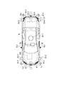
- FIG. 1 is a diagram showing components of a vehicle (hereinafter referred to as a host vehicle M) on which the vehicle control system 100 of the embodiment is mounted.
- the vehicle on which the vehicle control system 100 is mounted is, for example, a two-, three-, or four-wheeled vehicle, such as a vehicle powered by an internal combustion engine such as a diesel engine or gasoline engine, or an electric vehicle powered by a motor.
- hybrid vehicles having an internal combustion engine and an electric motor.
- An electric car is driven using electric power discharged by cells, such as a secondary battery, a hydrogen fuel cell, a metal fuel cell, and an alcohol fuel cell, for example.
- the vehicle M has sensors such as finders 20-1 to 20-7, radars 30-1 to 30-6, and a camera 40, a navigation device 50, and direction indicators TL1 to TL6. And the vehicle control system 100 are mounted.
- sensors such as finders 20-1 to 20-7, radars 30-1 to 30-6, and a camera 40, a navigation device 50, and direction indicators TL1 to TL6.
- vehicle control system 100 are mounted.
- the finders 20-1 to 20-7 are, for example, LIDAR (Light Detection and Ranging, or Laser Imaging Detection and Ranging) which measures the scattered light with respect to the irradiation light and measures the distance to the object.
- LIDAR Light Detection and Ranging, or Laser Imaging Detection and Ranging
- the finder 20-1 is attached to a front grill or the like
- the finders 20-2 and 20-3 are attached to the side of a vehicle body, a door mirror, the inside of a headlight, the vicinity of a side light, or the like.
- the finder 20-4 is attached to the trunk lid or the like
- the finders 20-5 and 20-6 are attached to the side of the vehicle body, the inside of the taillight, or the like.
- the finders 20-1 to 20-6 described above have, for example, a detection area of about 150 degrees in the horizontal direction.
- the finder 20-7 is attached to the roof or the like.
- the finder 20-7 has, for example, a detection area of 360 degrees in the horizontal direction.
- the radars 30-1 and 30-4 are, for example, long-distance millimeter-wave radars whose detection region in the depth direction is wider than other radars.
- the radars 30-2, 30-3, 30-5, and 30-6 are middle-range millimeter-wave radars that have a narrower detection area in the depth direction than the radars 30-1 and 30-4.
- the radar 30 detects an object by, for example, a frequency modulated continuous wave (FM-CW) method.
- FM-CW frequency modulated continuous wave
- the camera 40 is, for example, a digital camera using an individual imaging device such as a charge coupled device (CCD) or a complementary metal oxide semiconductor (CMOS).
- the camera 40 is attached to the top of the front windshield, the rear of the rearview mirror, and the like.
- the camera 40 for example, periodically and repeatedly images the front of the host vehicle M.
- the camera 40 may be a stereo camera including a plurality of cameras.
- the direction indicators TL1 to TL6 operate, for example, under the control of the vehicle control system 100.
- the direction indicators TL1 to TL6 include, for example, turn lamps that repeatedly turn on and off (flashing) in the operating state and turn off in the non-operating state.
- the direction indicators TL1 to TL6 may be constantly lit in the operating state.
- the direction indicators TL1 and TL2 are provided at the front end of the vehicle body such as the inside of a headlight
- the direction indicators TL3 and TL4 are provided at the side surface of the vehicle body, a door mirror, etc.
- the direction indicators TL5 and TL6 are It is provided at the rear end of the car body such as inside the taillight.
- the direction indicators TL3 and TL4 may be integral with the side lights, and the direction indicators TL5 and TL6 may be integral with a taillight such as a hazard lamp.
- a taillight such as a hazard lamp.
- the configuration shown in FIG. 1 is merely an example, and a part of the configuration may be omitted, or another configuration may be added.
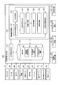
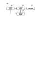
- FIG. 2 is a functional configuration diagram of a host vehicle M equipped with the vehicle control system 100 according to the embodiment.
- the navigation apparatus 50 the vehicle sensor 60, the display unit 62, the speaker 64, the accelerator pedal, the brake pedal, and the shift lever (or paddle shift)
- An operation device (an operator) 70 such as a steering wheel, and an operation detection sensor 72 such as an accelerator opening sensor, a brake depression sensor (brake switch), a shift position sensor, a steering angle sensor (or a steering torque sensor);
- a changeover switch 80, a driving force output device 90 for outputting a driving force for traveling, a steering device 92, a braking device 94, and a vehicle control system 100 are mounted.
- a multiplex communication line such as a CAN (Controller Area Network) communication line, a serial communication line, a wireless communication network or the like.
- the illustrated operation device is merely an example, and a joystick, a button, a dial switch, a GUI (Graphical User Interface) switch, etc. may be mounted on the vehicle M.
- the vehicle control system in the claims may include not only the vehicle control system 100 but also a configuration (such as the finder 20) other than the vehicle control system 100 among the configurations shown in FIG.
- the navigation device 50 has a GNSS (Global Navigation Satellite System) receiver, map information (navigation map), a touch panel display device functioning as a user interface, a speaker, a microphone, and the like.
- the navigation device 50 specifies the position of the host vehicle M by the GNSS receiver, and derives the route from the position to the destination specified by the user.
- the route derived by the navigation device 50 is provided to the target lane determination unit 110 of the vehicle control system 100.
- the position of the host vehicle M may be identified or supplemented by an INS (Inertial Navigation System) using the output of the vehicle sensor 60.
- INS Inertial Navigation System
- the navigation device 50 provides guidance by voice or navigation display on the route to the destination.
- the configuration for specifying the position of the host vehicle M may be provided independently of the navigation device 50.
- the navigation device 50 may be realized by, for example, the function of a terminal device such as a smartphone or a tablet terminal owned by the user. In this case, transmission and reception of information are performed between the terminal device and the vehicle control system 100 by wireless or wired communication.
- the vehicle sensor 60 includes a vehicle speed sensor that detects a vehicle speed, an acceleration sensor that detects an acceleration, a yaw rate sensor that detects an angular velocity about a vertical axis, an orientation sensor that detects the direction of the host vehicle M, and the like.
- the display unit 62 displays information as an image.
- the display unit 62 includes, for example, a liquid crystal display (LCD), an organic electroluminescence (EL) display device, a head-up display, and the like.
- the display unit 62 may be a display unit provided in the navigation device 50 or a display unit of an instrument panel that displays the state (speed, etc.) of the host vehicle M.
- the speaker 64 outputs the information as sound.
- the operation detection sensor 72 detects the amount of operation of the operation device 70.
- the operation detection sensor 72 outputs, to the vehicle control system 100, an accelerator opening degree, a brake depression amount, a shift position, a steering angle, a steering torque, and the like as detection results.
- the detection result of the operation detection sensor 72 may be directly output to the driving force output device 90, the steering device 92, or the brake device 94 depending on the operation mode.
- the changeover switch 80 is a switch operated by a vehicle occupant.
- the switch 80 receives an operation of the vehicle occupant, generates a driving mode designation signal for specifying the driving mode of the host vehicle M, and outputs the driving mode designation signal to the switching control unit 170.
- the changeover switch 80 may be either a GUI switch or a mechanical switch.
- the driving force output device 90 outputs traveling driving force (torque) for the vehicle to travel to the driving wheels.
- the driving force output device 90 includes an engine, a transmission, and an engine ECU (Electronic Control Unit) that controls the engine.
- the driving force output device 90 includes a traveling motor and a motor ECU that controls the traveling motor.
- the driving force output device 90 includes an engine, a transmission, an engine ECU, a traveling motor, and a motor ECU.
- the engine ECU adjusts the throttle opening degree, shift stage, and the like of the engine according to the information input from the traveling control unit 160 described later.
- the motor ECU adjusts the duty ratio of the PWM signal given to the traveling motor in accordance with the information input from the traveling control unit 160.
- the driving force output device 90 includes an engine and a traveling motor, the engine ECU and the motor ECU control the traveling driving force in coordination with each other in accordance with the information input from the traveling control unit 160.
- the steering device 92 includes, for example, a steering ECU and an electric motor.
- the electric motor for example, applies a force to the rack and pinion mechanism to change the direction of the steered wheels.
- the steering ECU drives the electric motor according to the information input from the vehicle control system 100 or the information of the steering angle or steering torque input, and changes the direction of the steered wheels.
- the brake device 94 is, for example, an electric servo brake device including a brake caliper, a cylinder that transmits hydraulic pressure to the brake caliper, an electric motor that generates hydraulic pressure in the cylinder, and a braking control unit.
- the braking control unit of the electric servo brake device controls the electric motor in accordance with the information input from the traveling control unit 160 so that the brake torque corresponding to the braking operation is output to each wheel.
- the electric servo brake device may be provided with a mechanism for transmitting the hydraulic pressure generated by the operation of the brake pedal to the cylinder via the master cylinder as a backup.
- the brake device 94 is not limited to the electric servo brake device described above, but may be an electronically controlled hydraulic brake device.
- the electronically controlled hydraulic brake device controls the actuator according to the information input from the travel control unit 160 to transmit the hydraulic pressure of the master cylinder to the cylinder.
- the brake device 94 may include a regenerative brake by a traveling motor that may be included in the driving force output device 90.
- the regenerative brake uses the electric power generated by the traveling motor which may be included in the driving force output device 90.
- the vehicle control system 100 is realized by, for example, one or more processors or hardware having equivalent functions.
- the vehicle control system 100 may have a combination of a processor such as a central processing unit (CPU), a storage device, an ECU in which a communication interface is connected by an internal bus, or an MPU.
- a processor such as a central processing unit (CPU), a storage device, an ECU in which a communication interface is connected by an internal bus, or an MPU.
- the vehicle control system 100 includes, for example, a target lane determination unit 110, an automatic driving control unit 120, and a storage unit 190.
- the autonomous driving control unit 120 includes a vehicle position recognition unit 122, an external world recognition unit 130, an action plan generation unit 140, a track generation unit 150, a travel control unit 160, a switching control unit 170, and direction instructions. And a controller control unit 180.
- the track generation unit 150 and the travel control unit 160 are examples of a “control unit”.
- the processor executes a program (software) to realize part or all of the target lane determination unit 110 and each part of the autonomous driving control unit 120. Also, some or all of these may be realized by hardware such as LSI (Large Scale Integration) or ASIC (Application Specific Integrated Circuit), or may be realized by a combination of software and hardware.
- LSI Large Scale Integration
- ASIC Application Specific Integrated Circuit
- the storage unit 190 stores, for example, information such as high accuracy map information 192, target lane information 194, action plan information 196, and the like.
- the storage unit 190 is realized by a read only memory (ROM), a random access memory (RAM), a hard disk drive (HDD), a flash memory, or the like.
- the program executed by the processor may be stored in advance in the storage unit 190, or may be downloaded from an external device via an in-vehicle Internet facility or the like.
- the program may be installed in the storage unit 190 by mounting a portable storage medium storing the program in a drive device (not shown).
- the vehicle control system 100 may be distributed by a plurality of computer devices.
- the target lane determination unit 110 is realized by, for example, an MPU.
- the target lane determination unit 110 divides the route provided from the navigation device 50 into a plurality of blocks (for example, in units of 100 [m] in the traveling direction of the vehicle), and refers to the high accuracy map information 192 for each block Determine your target lane.
- the target lane determination unit 110 determines, for example, which lane from the left the vehicle should travel.
- the target lane determination unit 110 determines the target lane so that the host vehicle M can travel on a rational travel route for advancing to the branch destination, for example, when there is a branch point or a junction point in the route. .
- the target lane determined by the target lane determination unit 110 is stored in the storage unit 190 as target lane information 194.
- the high accuracy map information 192 is map information that is more accurate than the navigation map of the navigation device 50.
- the high accuracy map information 192 includes, for example, information on the center of the lane or information on the boundary of the lane. Also, the high accuracy map information 192 may include road information, traffic regulation information, address information (address / zip code), facility information, telephone number information, and the like.
- the road information includes information indicating the type of road such as expressways, toll roads, national roads, and prefectural roads, the number of lanes of the road, the width of each lane, the slope of the road, the position of the road (longitude, latitude, height 3) (including three-dimensional coordinates), curvature of a curve of a lane, locations of merging and branching points of lanes, and information such as signs provided on roads.
- the traffic regulation information includes information that the lane is blocked due to construction work, traffic accident, traffic jam or the like.
- the vehicle position recognition unit 122 of the automatic driving control unit 120 receives information from the high accuracy map information 192 stored in the storage unit 190, the finder 20, the radar 30, the camera 40, the navigation device 50, or the vehicle sensor 60. And recognizes the relative position of the host vehicle M with respect to the travel lane and the lane in which the host vehicle M is traveling (traveling lane).
- FIG. 3 is a diagram showing how the vehicle position recognition unit 122 recognizes the relative position of the vehicle M with respect to the traveling lane L1.
- the host vehicle position recognition unit 122 receives the deviation OS from the center CL of the travel lane of the reference point (for example, the center of gravity or the center of the rear wheel axis) of the host vehicle M and the center CL of the travel lane
- the angle ⁇ to be formed is recognized as the relative position of the host vehicle M with respect to the traveling lane L1.
- the host vehicle position recognition unit 122 recognizes the position of the reference point of the host vehicle M with respect to any one side end of the host lane L1 as the relative position of the host vehicle M with respect to the traveling lane. It is also good.
- the relative position of the host vehicle M recognized by the host vehicle position recognition unit 122 is provided to the target lane determination unit 110.
- the external world recognition unit 130 recognizes the position of the surrounding vehicle and the state of the speed, acceleration, and the like based on the information input from the finder 20, the radar 30, the camera 40 and the like.
- the surrounding vehicle is, for example, a vehicle traveling around the host vehicle M and traveling in the same direction as the host vehicle M.
- the position of the surrounding vehicle may be represented by a representative point such as the center of gravity or a corner of the other vehicle, or may be represented by an area represented by the contour of the other vehicle.
- the "state" of the surrounding vehicle may include the acceleration of the surrounding vehicle, whether it is changing lanes (or whether it is going to change lanes), which is grasped based on the information of the various devices.
- the external world recognition unit 130 recognizes the position of the driver in the recognized peripheral vehicle. For example, the external world recognition unit 130 estimates the position of the window frame from the shape of the vehicle body of the surrounding vehicle, predicts the seat position of the driver from the arrangement pattern of the window frame, and recognizes this predicted position as the driver position. Do. In addition, the external world recognition unit 130 may recognize the position of the driver by estimating the seat position in the vehicle based on the position of the door mirror of the peripheral vehicle, the position of the wheel (tire), and the like.
- the external world recognition unit 130 may perform image processing such as feature point matching on the captured image of the camera 40 to recognize the position of the driver (human) from the captured image, or the finder 20 or The position of the driver may be recognized by performing analysis processing of a spectrum indicating characteristics of light and radio waves reflected by a human on the detection result by the radar 30.
- the outside world recognition unit 130 may also recognize positions of guardrails, utility poles, parked vehicles, pedestrians, and other objects.
- the external world recognition unit 130 is configured to drop objects on the roadway, stop nearby vehicles, targets in the vicinity of the construction site (for example, pylons and billboards), and walk on the target lane determined by the target lane determination unit 110. Recognize obstacles such as people.
- the action plan generation unit 140 sets a start point of the autonomous driving and / or a destination of the autonomous driving.
- the starting point of the autonomous driving may be the current position of the host vehicle M or a point at which the operation for instructing the autonomous driving is performed.
- the action plan generation unit 140 generates an action plan in the section between the starting point and the destination of the automatic driving.
- generation part 140 may produce
- the action plan is composed of, for example, a plurality of events that are sequentially executed.
- Events include, for example, a deceleration event for decelerating the host vehicle M, an acceleration event for accelerating the host vehicle M, a lane keep event for traveling the host vehicle M not to deviate from the target lane, and a lane change event for changing the target lane
- an overtaking event that causes the host vehicle M to overtake the preceding vehicle
- a branch event that changes the lane to a desired lane at a branch point, or causes the host vehicle M to travel so as not to deviate from the current target lane.
- a merging event or the like which accelerates / decelerates the host vehicle M in the confluence lane of and changes the target lane is included.
- the action plan generation unit 140 sets a lane change event, a branch event, or a merging event at a point where the target lane determined by the target lane determination unit 110 is switched.
- Information indicating the action plan generated by the action plan generation unit 140 is stored in the storage unit 190 as action plan information 196.
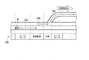
- FIG. 4 is a diagram showing an example of an action plan generated for a certain section.
- the action plan generation unit 140 generates an action plan necessary for the host vehicle M to travel on the target lane indicated by the target lane information 194.
- the action plan generation unit 140 may dynamically change the action plan according to the change in the situation of the host vehicle M, regardless of the target lane information 194. For example, in the action plan generation unit 140, the speed of the peripheral vehicle recognized by the external world recognition unit 130 exceeds the threshold while the vehicle is traveling, or the movement direction of the peripheral vehicle traveling in the lane adjacent to the own lane In the case of turning, the event set in the driving section where the host vehicle M is to travel is changed.
- the recognition result of the external world recognition unit 130 causes the vehicle to exceed the threshold from the rear of the lane in the lane change destination during the lane keep event. If it is determined that the vehicle has progressed at the speed of 1, the action plan generation unit 140 may change the event following the lane keeping event from a lane change event to a deceleration event or a lane keeping event. As a result, the vehicle control system 100 can safely cause the host vehicle M to travel automatically even when a change occurs in the state of the outside world.
- FIG. 5 is a diagram showing an example of the configuration of the trajectory generation unit 150.
- the track generation unit 150 includes, for example, a traveling mode determination unit 151, a track candidate generation unit 152, an evaluation / selection unit 153, and a lane change control unit 154.
- the traveling mode determination unit 151 determines one of the traveling modes among constant speed traveling, follow-up traveling, deceleration traveling, curve traveling, obstacle avoidance traveling, and the like. For example, when there is no other vehicle ahead of the host vehicle M, the traveling mode determination unit 151 determines that the traveling mode is constant speed traveling. In addition, the traveling mode determination unit 151 determines the traveling mode as the following traveling when following the traveling vehicle. Further, the traveling mode determining unit 151 determines the traveling mode to be the decelerating traveling when the external world recognition unit 130 recognizes the deceleration of the leading vehicle, or when an event such as stopping or parking is performed.
- the traveling mode determination unit 151 determines the traveling mode to be a curve traveling when the external world recognition unit 130 recognizes that the host vehicle M is approaching a curved road. In addition, when the external world recognition unit 130 recognizes an obstacle ahead of the host vehicle M, the traveling mode determination unit 151 determines the traveling mode as obstacle avoidance traveling.
- the track candidate generation unit 152 generates track candidates based on the traveling mode determined by the traveling mode determination unit 151.
- the track in the present embodiment is a set of target positions (track points) to be reached by the reference point (for example, the center of gravity or the rear wheel axis center) of the vehicle M at predetermined future time intervals (or at predetermined travel distances). .
- the trajectory candidate generation unit 152 sets the target velocity of the host vehicle M based on at least the speed of the target OB existing in front of the host vehicle M recognized by the external world recognition unit 130 and the distance between the host vehicle M and the target OB. calculate.
- the trajectory candidate generation unit 152 generates one or more trajectories based on the calculated target velocity.
- the target OB includes a vehicle ahead, a junction such as a junction, a junction, a point such as a target point, and an object such as an obstacle.
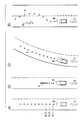
- FIG. 6 is a diagram showing an example of trajectory candidates generated by the trajectory candidate generation unit 152. As shown in FIG. In FIG. 6 and FIG. 9 described later, only representative trajectories or trajectories selected by the evaluation / selection unit 153 out of a plurality of trajectory candidates that can be set will be described. As shown in (A) of FIG. 6, for example, the trajectory candidate generation unit 152 sets K (1) and K (2) every time a predetermined time ⁇ t has elapsed from the current time based on the current position of the host vehicle M. , K (3),... Hereinafter, when these orbital points are not distinguished, they may be simply described as "orbital point K".
- the trajectory candidate generation unit 152 sets a plurality of trajectory points K at equal intervals as shown in (A) in FIG.
- the trajectory candidate generation unit 152 may generate only one trajectory.
- the track candidate generation unit 152 is reached as shown in (B) in FIG.
- the interval is made wider as the trajectory point K is earlier, and the trajectory is made narrower as the trajectory point K is later.
- a leading vehicle may be set as the target OB, or a junction other than the leading vehicle, a branch point, a point such as a target point, an obstacle, or the like may be set as the target OB.
- the traveling control unit 160 described later decelerates the host vehicle M.
- the trajectory candidate generation unit 152 When the traveling mode is determined to be curve traveling by the traveling mode determination unit 151, as illustrated in (C) in FIG. 6, the trajectory candidate generation unit 152 performs a plurality of trajectory points K according to the curvature of the road. Arrange while changing the lateral position (position in the lane width direction) to the traveling direction of M. Further, as shown in (D) of FIG. 6, when there is an obstacle OB such as a person or a stopped vehicle on the road in front of the own vehicle M, the trajectory candidate generation unit 152 avoids the obstacle OB. A plurality of track points K are arranged so as to travel.
- the evaluation / selection unit 153 evaluates the track candidates generated by the track candidate generation unit 152, for example, from two viewpoints of planability and safety, and selects a track to be output to the traveling control unit 160. .
- the track is highly evaluated if the trackability to the already generated plan (for example, the action plan) is high and the total length of the track is short. For example, if it is desired to change lanes to the right, a track that once changes lanes to the left and then back is a low rating.
- viewpoint of safety for example, the distance between the host vehicle M and an object (such as a surrounding vehicle) is longer, and the smaller the acceleration / deceleration, the change amount of the steering angle, etc.
- the lane change control unit 154 operates when a lane change event, a branch event, a merging event or the like is performed, that is, when a broad lane change is performed.
- FIG. 7 is a flowchart showing an example of the flow of processing executed when a lane change event is performed. The process will be described with reference to FIGS. 7 and 8.
- the lane change control unit 154 selects two peripheral vehicles from the adjacent vehicles that are adjacent lanes adjacent to the lane where the host vehicle M is traveling (the own lane) and that travels in the adjacent lanes of the lane change destination.
- the target position TA is set between these surrounding vehicles (step S100).
- peripheral vehicles traveling immediately before the target position TA in the adjacent lane will be referred to as a front reference vehicle mB
- peripheral vehicles traveling immediately after the target position TA in the adjacent lane will be referred to as a rear reference vehicle mC.
- the target position TA is a relative position based on the positional relationship between the host vehicle M and the front reference vehicle mB and the rear reference vehicle mC.
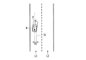
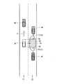
- FIG. 8 is a diagram showing how the target position TA is set.
- mA represents a front vehicle
- mB represents a front reference vehicle
- mC represents a rear reference vehicle.
- the arrow d indicates the traveling (traveling) direction of the host vehicle M
- L1 indicates the host lane
- L2 indicates the adjacent lane.
- the lane change control unit 154 sets the target position TA between the front reference vehicle mB and the rear reference vehicle mC on the adjacent lane L2.
- the lane change control unit 154 determines whether the primary condition for determining whether the lane change is possible at the target position TA (that is, between the front reference vehicle mB and the rear reference vehicle mC) is satisfied or not. It determines (step S102).
- the primary condition is that, for example, there are no surrounding vehicles in the prohibited area RA provided in the adjacent lane, and TTCs of the own vehicle M and the front reference vehicle mB and the rear reference vehicle mC are respectively larger than the threshold It is.
- this determination condition is an example when the target position TA is set on the side of the host vehicle M. If the primary condition is not satisfied, the lane change control unit 154 returns the process to step S100 and resets the target position TA. At this time, speed control for moving to the side of the target position TA is performed by waiting until the timing at which the target position TA that satisfies the primary condition can be set or changing the target position TA. May be
- the lane change control unit 154 projects the vehicle M on the lane L2 as the lane change destination, and sets a prohibited area RA with a slight allowance distance before and after.
- the prohibited area RA is set as an area extending from one end of the lane L2 in the lateral direction to the other end.
- the lane change control unit 154 calculates the extension line FM and the collision margin time TTC (B) of the front reference vehicle mB, and the rear line reference vehicle TTC (C) of the extension line RM and the rear reference vehicle mC.
- the collision margin time TTC (B) is a time derived by dividing the distance between the extension line FM and the front reference vehicle mB by the relative speed of the host vehicle M and the front reference vehicle mB.
- the collision margin time TTC (C) is a time derived by dividing the distance between the extension line RM and the rear reference vehicle mC by the relative speed of the host vehicle M and the rear reference vehicle mC.
- the trajectory candidate generation unit 152 determines that the primary condition is satisfied when the collision margin time TTC (B) is larger than the threshold Th (B) and the collision margin time TTC (C) is larger than the threshold Th (C). Do.
- the thresholds Th (B) and Th (C) may be the same value or different values.
- the lane change control unit 154 causes the trajectory candidate generation unit 152 to generate a trajectory candidate for lane change (step S104).
- FIG. 9 is a diagram showing how a track for lane change is generated.
- the track candidate generation unit 152 assumes that the front vehicle mA, the front reference vehicle mB and the rear reference vehicle mC travel with a predetermined speed model, and the speed models of these three vehicles and the speed of the host vehicle M And generates a candidate for a trajectory such that the host vehicle M is located between the front reference vehicle mB and the rear reference vehicle mC at a certain time in the future without interference or contact with the forward vehicle mA. .
- the track candidate generation unit 152 generates a spline curve or the like from the current position of the host vehicle M to the position of the front reference vehicle mB at a certain time in the future, the center of the lane to be changed, and the lane change end point It connects smoothly using a polynomial curve, and a predetermined number of orbital points K are arranged on this curve at equal or unequal intervals.
- the trajectory candidate generation unit 152 generates a trajectory such that at least one of the trajectory points K is disposed within the target position TA.
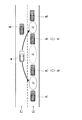
- FIG. 10 is a diagram showing an example of the scene where the target position TA is reset.
- the lane change control unit 154 refers to the rear reference vehicle mC referenced when setting the target position TA.
- a new front reference vehicle mB is set, and a vehicle existing behind the newly set front reference vehicle mB is set as a new rear reference vehicle mC, and the reset front reference vehicle mB and rear reference vehicle mC are set. And reset the target position TA.
- the lane change control unit 154 similarly sets the front reference vehicle mB referred to when setting the target position TA as a new rear reference vehicle mC, and in front of the newly set rear reference vehicle mC.
- the existing vehicle may be set as a new front reference vehicle mB, and the target position TA may be reset between the reset front reference vehicle mB and the rear reference vehicle mC.
- the track candidate generation unit 152 generates a track for changing the lane of the host vehicle M between the reset front reference vehicle mB and the rear reference vehicle mC.
- the evaluation / selection unit 153 determines whether or not the trajectory candidate satisfying the setting condition has been generated (step S106).
- the setting condition is, for example, that an evaluation value equal to or greater than a threshold value is obtained from the viewpoint of the planability and safety described above.
- the evaluation / selection unit 153 selects, for example, the candidate of the track with the highest evaluation value, outputs information of the track to the travel control unit 160, and causes lane change. (Step S108).
- step S100 if a trajectory satisfying the set condition can not be generated, the process returns to step S100. At this time, as in the case where a negative determination is obtained in step S102, processing may be performed to be in the standby state or to reset the target position TA.
- the traveling control unit 160 controls the driving force output device 90, the steering device 92, and the braking device 94 so that the vehicle M passes the track generated by the track candidate generating unit 152 as scheduled.
- the switching control unit 170 switches the driving mode based on an operation for instructing the operating device 70 to accelerate, decelerate or steer, as well as switching the driving mode based on the driving mode designation signal input from the changeover switch 80. For example, the switching control unit 170 switches from the automatic driving mode to the manual driving mode when the state where the operation amount input from the operation detecting sensor 72 exceeds the threshold continues for the reference time or more. In addition, the switching control unit 170 switches the operation mode from the automatic operation mode to the manual operation mode near the destination of the automatic operation.
- the switching control unit 170 When switching from the manual operation mode to the automatic operation mode, the switching control unit 170 performs this based on the operation mode designation signal input from the switching switch 80. In addition, after switching from the automatic driving mode to the manual driving mode, if the operation for instructing the operating device 70 to accelerate, decelerate or steer is not detected for a predetermined time, control to return to the automatic driving mode is performed. It may be
- FIG. 11 is a diagram showing an example of the configuration of the direction indicator control unit 180.
- the direction indicator control unit 180 includes, for example, an operation timing determination unit 181, an operation continuation determination unit 182, and an operation control unit 183.
- the operation timing determination unit 181 causes the vehicle M and one or both of the front reference vehicle mB and the rear reference vehicle mC to Set the reference position to be referenced when comparing the position of.
- the reference position to be set to the host vehicle M is denoted by reference symbol CP M
- the reference position to be set to the front reference vehicle mB is denoted by reference symbol CP mB
- the reference position to be set to the rear reference vehicle mC is denoted by CP mC Do.
- Operation timing determination unit 181 compares the reference position CP M of the vehicle M, and one or both of the reference position CP mC reference position CP mB and rear reference vehicle mC forward reference vehicle mB, direction indicator Determine the timing to operate the machine TL.
- the reference position CPM of the host vehicle M is, for example, a position where the direction indicator TL is provided, and the installation position of the direction indicators TL1 and TL2 on the front end of the vehicle, and the direction indicators TL3 and TL4 on the vehicle side. It may be either the installation position, the installation position of the direction indicators TL5 and TL6 on the rear end side of the vehicle, or the center of these positions.
- the reference position CP mB of the front reference vehicle mB and the reference position CP mC of the rear reference vehicle mC are, for example, positions of drivers of the respective vehicles.
- the actuation timing determination unit 181 determines that the reference position CP mB of the forward reference vehicle mB matches the reference position CP M of the subject vehicle M. or compared to the reference position CP mB of the forward reference vehicle mB, the reference position CP M of the own vehicle M, the timing at which the rear with respect to the traveling direction of the vehicle (timing later than the matching timing), the target position It is decided to activate the turn indicator TL on the adjacent lane side where TA is set.
- the "target position TA is behind the vehicle", for example, the reference position CP M of the vehicle M than the reference position CP mB of the forward reference vehicle mB referenced when setting the target position TA is self It means being forward with respect to the direction of travel of the vehicle.
- the operation timing determining unit 181 if the target position TA set in the adjacent lane is ahead of the vehicle, and the reference position CP M of the reference position CP mC and the vehicle M of backward reference vehicle mC match timing or compared to the reference position CP mC backward reference vehicle mC, the reference position CP M of the own vehicle M, the timing at which the front with respect to the traveling direction of the vehicle (timing later than the matching timing), the target position The timing is determined as the timing at which the turn indicator TL on the adjacent lane side where the TA is set is activated.
- the "target position TA is ahead of the vehicle", for example, the reference position CP M of the vehicle M than the reference position CP mC backward reference vehicle mC referenced when setting the target position TA is self It says that it is the rear in the direction of movement of the vehicle.
- the operation timing determining section 181 the reference position CP M of the own vehicle M, it becomes forward than the reference position CP mC backward reference vehicle mC described above, the ratio to the reference position CP mB of the forward reference vehicle mB It is also possible to decide to activate the turn indicator TL on the adjacent lane side where the target position TA has been set, at the timing when it comes to the rear.
- the operation continuation determination unit 182 is a direction indicator based on the change of the action plan (event) by the action plan generation unit 140, the determination of the possibility of the lane change by the lane change control unit 154, the switching of the control mode by the switching control unit 170, etc. After TL is activated, it is determined whether to continue lighting (flashing) or turning it off.
- the direction changer TL is activated, and the direction change event is changed to another event by the action plan generation unit 140 before the host vehicle M reaches the target position TA. It is decided to turn off the indicator TL.
- the operation continuation determination unit 182 determines to turn off the turn indicator TL when the switching control unit 170 switches to the manual operation mode by the operation by the driver during the automatic operation mode.
- the operation continuation determination unit 182 changes the lane by the rear reference vehicle mC approaching the front reference vehicle mB, etc. If it is continuously determined whether or not the lane change with respect to the other target position TA is to be made if the necessary inter-vehicle distance is not sufficiently secured, it is decided to continue the operation of the direction indicator TL.
- the operation control unit 183 operates (always lights or blinks) the turn indicator TL on the adjacent lane side where the target position TA is set at the timing determined by the operation timing determination unit 181. Further, the operation control unit 183 keeps the direction indicator TL activated or extinguished according to the determination result by the operation continuation determination unit 182.
- FIG. 12 is a flowchart showing an example of the flow of processing by the direction indicator control unit 180.
- the operation timing determination unit 181 determines whether the target position TA set by the lane change control unit 154 is ahead of the host vehicle (step S200). When the target position TA is in front of the host vehicle, the operation timing determination unit 181 derives the time when the reference position CP M of the host vehicle M reaches the reference position CP mC of the rear reference vehicle mC (step S202). For example, when the operation timing determination unit 181 sets the current speed of the host vehicle M and the speed of the rear reference vehicle mC constant, the relative distance from the reference position CP M to the reference position CP mC is constant. The operation time of the turn indicator TL is derived by deriving the time required to run through the road.
- the operation timing determination unit 181 derives the time when the reference position CP mB of the front reference vehicle mB reaches the reference position CPM of the vehicle M (Step S204). For example, when the operation timing determination unit 181 sets the current speed of the host vehicle M and the speed of the forward reference vehicle mB constant, the relative distance from the forward reference vehicle mB to the reference position CP M from the reference position CP mB The operation time of the turn indicator TL is derived by calculating the time required to run through the road.
- the operation control unit 183 waits until the current time reaches the operation time derived by the operation timing determination unit 181 (step S206), and the timing when the current time becomes the operation time or from the operation time
- the turn indicator TL is activated at the timing when a certain remaining time has passed (step S208).
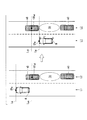
- FIG. 13 is a view showing an example of a scene in which the target position TA is set in front of the host vehicle M.
- the turn indicator TL indicates that the reference position CPM of the host vehicle M coincides with the reference position CP mC of the rear reference vehicle mC, or the reference position CP mC of the rear reference vehicle mC is the host It is operated at a timing behind the M reference position CPM.
- the reference position CP M of the vehicle M may be a right front turn signals TL2, middle right turn signal TL4, it may be a right rear direction indicators TL6.
- the operation timing determination unit 181 sets a reference line L mC virtually extended in the lane width direction from the reference position CP mC of the rear reference vehicle mC, and a reference position CP of the own vehicle M. Assuming a reference line LM virtually extending in the lane width direction from M , the operation timing is determined from the anteroposterior relationship between these reference lines.
- Direction indicator control unit 180 by operating the reference line L M timing coincides with the reference line L mC or reference line L M is the reference line L direction indicator TL at the timing located behind the mC,, e.g.
- the intention of the host vehicle M to break in front of the rear reference vehicle mC can be transmitted to the driver of the rear reference vehicle mC, and the driver of the rear reference vehicle mC can be considered.
- FIG. 14 is a diagram showing an example of a scene in which the target position TA is set to the rear of the host vehicle M.
- the turn indicator TL indicates that the reference position CPM of the host vehicle M coincides with the reference position CP mB of the front reference vehicle mB, or that the reference position CP mB of the front reference vehicle mB is the host It is operated at the timing ahead of the reference position CPM of M.
- the reference position CP M of the vehicle M is preferably a right front turn signal TL2.
- the operation timing determination unit 181 assumes a reference line L mB virtually extended in the lane width direction from the reference position CP mB of the front reference vehicle mB and the reference line L M.
- the operation timing is determined from the anteroposterior relationship between these reference lines.
- Direction indicator control unit 180 by operating the reference line L M is the reference line L mB Match timing or the reference line L M is the reference line L direction indicator TL at the timing located in front of the mB, e.g. It is possible to prevent misunderstanding that the lighting of the direction indicator TL is less likely to be visually recognized by the driver of the front reference vehicle mB, and has an intention to cut in front of the front reference vehicle mB.
- the actuation continuation determination unit 182 determines whether or not the lane change is completed (FIG. 12: step S210). When the lane change is completed, the operation control unit 183 turns off the operated direction indicator TL (step S212).
- the operation continuation determination unit 182 determines whether the target position TA is reset by the lane change control unit 154 (step S214). When the target position TA is not reset, the operation continuation determination unit 182 determines that the lane change event has been changed to another event or the operation mode has been switched to the automatic operation mode, and the operation control unit 183 described above. The processing of S212 is performed.
- the operation continuation determination unit 182 determines to continue the operation (step S216), and returns to the process of S200 described above.
- the process of this flowchart is complete
- FIG. 15 is a diagram showing an example of a situation in which the operation of the turn indicator TL is continued.
- the target position TA1 is set between the vehicle m1 and the vehicle m2 by the lane change control unit 154
- the traveling control unit 160 controls the driving force output device 90, the steering device 92, and the braking device 94 to control the vehicle M.
- the vehicle travels toward the target position TA1.
- the turn signal control unit 180 the reference position CP M of the vehicle M overtakes the reference position CP mC vehicle m2 is a rear reference vehicle mC, operates the direction indicator TL, the driver of the vehicle m2 Tell your intention to interrupt.
- the vehicle m2 may accelerate and a sufficient inter-vehicle distance may not be secured between the vehicle m1 and the vehicle m2.
- the lane change control unit 154 newly resets the target position TA2 between the vehicle m2 and the vehicle m3. If it is determined that the lane change is possible for this target position TA2, the direction indicator control unit 180 continues the operation of the direction indicator TL.
- the vehicle control system 100 causes the host vehicle M to travel toward the target position TA2
- the vehicle control system 100 transmits the intention to change lanes to drivers of surrounding vehicles by constantly operating the direction indicator TL. Can.
- the possibility that the host vehicle M can change lanes to the adjacent lane L2 is improved.
- the direction indicator TL is operated based on the relative position between the front reference vehicle mB traveling immediately before the target position TA or the rear reference vehicle mC traveling immediately after and the host vehicle M.
- the timing is determined. Therefore, it is possible to give notice of lane change at an appropriate timing.
- the timing reference position CP M of the vehicle M is equal to the reference position CP mC backward reference vehicle mC or reference position CP mC backward reference vehicle mC is the vehicle M based direction indicator TL is operated at timing at which the rear position CP M. Therefore, the intention of the host vehicle M to break in front of the rear reference vehicle mC can be transmitted to the driver of the rear reference vehicle mC, and the driver of the rear reference vehicle mC can be considered.
- the timing reference position CP M of the vehicle M is equal to the reference position CP mB of the forward reference vehicle mB
- the reference position CP mB of the forward reference vehicle mB of the vehicle M based direction indicator TL is operated at timing at which the forward position CP M. Therefore, it is difficult for the driver of the front reference vehicle mB to visually recognize that the turn indicator TL is lit, and it is possible to prevent misunderstanding that the driver has an intention to cut in front of the front reference vehicle mB.
- the turn indicator TL is not turned off even when it is not possible to change the lane for one target position TA, and while the lane change feasibility determination for the other target positions TA is performed.
- the turn indicator TL continues to operate. Therefore, the certainty of lane change can be enhanced.
- the operation timing determination unit 181 described above changes the setting position of the reference position CP mB based on the relative speed between the host vehicle M and the front reference vehicle mB.
- the operation timing determination unit 181 changes the setting position of the reference position CP mC based on the relative speed of the host vehicle M and the rear reference vehicle mC.
- FIG. 16 is a diagram for describing a method of determining the setting positions of the reference positions CP mB and CP mC .
- the horizontal axis represents the setting position of the reference position CP mB and CP mC, vertical axis, and the velocity V M of the vehicle M, the speed of the speed V mB or rear reference vehicle mC forward reference vehicle mB It represents the relative velocity with VmC .
- the reference position CP mC is higher as the velocity V M of the host vehicle M is larger than the speed V mC of the rear reference vehicle mC.
- the actuation timing determination unit 181 sets the reference position CP mC to the rear reference as the relative velocity of the host vehicle M with respect to the rear reference vehicle mC increases as a positive value. It is set to be closer to the rear end side of the vehicle mC.
- the direction indicator control unit 180 operates the direction indicator TL earlier when the host vehicle M passes the rear reference vehicle mC.
- the direction indicator control unit 180 can more reliably perform the driver of the rear reference vehicle mC even in a situation where the error in the position of the rear reference vehicle mC recognized becomes larger as the relative speed increases.
- the lighting of the direction indicator TL can be visually recognized.
- the reference position CP mB is lower as the velocity VM of the host vehicle M is smaller than the speed V mB of the front reference vehicle mB.
- And is set to be closer to the front end side of the front reference vehicle mB.
- the operation timing determination unit 181 sets the reference position according to the relative speed of the host vehicle M relative to the front reference vehicle mB becoming a negative value.
- CP mB is set to be closer to the front end side of the front reference vehicle mB.
- the rear end of the front reference vehicle mB Since the reference position CP mB is set on the side, the turn indicator TL is turned on further rearward than the position of the driver of the front reference vehicle mB. As a result, it becomes more difficult for the driver of the front reference vehicle mB to visually recognize lighting of the direction indicator TL.
- the direction indicator TL is activated in front of the driver's position of the front reference vehicle mB.
- the forward reference vehicle mB is faster than the own vehicle M, the intention to change the lane of the own vehicle M tends to be ignored, and has an intention to cut in front of the forward reference vehicle mB. It is possible to activate the turn indicator TL earlier without giving a misunderstanding.
- FIG. 17 is a diagram showing an example of a scene in which the inter-vehicle distance between the front reference vehicle mB and the rear reference vehicle mC is enlarged.
- ⁇ L represents the inter-vehicle distance before the turn indicator TL is activated
- ⁇ L # represents the inter-vehicle distance after the turn indicator TL is activated.
- the turn indicator controller 180 changes the lane ahead of the rear reference vehicle mC, and then turns the turn indicators TL5 and TL6. Operate. Thereby, the vehicle control system 100 can convey the intention of appreciation to the driver of the rear reference vehicle mC.
Landscapes
- Engineering & Computer Science (AREA)
- Mechanical Engineering (AREA)
- Transportation (AREA)
- Automation & Control Theory (AREA)
- Traffic Control Systems (AREA)
- Control Of Driving Devices And Active Controlling Of Vehicle (AREA)
Abstract
This vehicle control system (100) is provided with: a control unit that sets a target position, which is used as a target when a host vehicle is made to change lanes, to an adjacent lane which is adjacent to a host vehicle lane along which the host vehicle is traveling, and causes the host vehicle to change lanes toward the target position; and a direction indicator control unit (180) that decides, on the basis of the relative relationship between the host vehicle and a vehicle that is traveling directly in front of or directly behind the target position set by the control unit, the timing at which a direction indicator provided in the host vehicle is actuated.
Description
本発明は、車両制御システム、車両制御方法、および車両制御プログラムに関する。
本願は、2016年3月15日に出願された日本国特願2016-051332号に基づき優先権を主張し、その内容をここに援用する。 The present invention relates to a vehicle control system, a vehicle control method, and a vehicle control program.
Priority is claimed on Japanese Patent Application No. 2016-051332, filed March 15, 2016, the content of which is incorporated herein by reference.
近年、自車両と周辺車両との相対関係に基づいて走行時に車線変更を自動で行う技術について研究が進められている。これに関連して、入力装置の入力に基づいて車線変更の支援を開始する支援開始部と、自車と他車の相対距離及び相対速度を検出する検出部と、検出部が検出した相対距離及び相対速度に基づいて自車が車線変更した時の衝突危険度を他車に対して算出する算出部と、相対距離,相対速度及び衝突危険度に基づいて車線変更の可否を判断する第1の判断部と、第1の判断部が車線変更できないと判断した場合、相対距離及び相対速度に基づいて車線変更する目標スペースを決定する決定部と、目標スペースに車線変更できるスペースがあるか否かを判断する第2の判断部と、第2の判断部が前記スペースがないと判断した場合、車線変更待機位置へ向けて目標速度を設定し、スペースがあると判断した場合、車線変更可能位置へ向けて目標速度を設定する設定部と、自車の速度が目標速度となるように制御する制御部とを備える走行支援装置が知られている(例えば、特許文献1参照)。
In recent years, research has been conducted on a technology for automatically changing lanes at the time of traveling based on the relative relationship between the host vehicle and surrounding vehicles. In relation to this, the support start unit that starts the support for the lane change based on the input of the input device, the detection unit that detects the relative distance and the relative speed of the own vehicle and the other vehicle, and the relative distance detected by the detection unit And a calculation unit that calculates the collision risk with respect to the other vehicle when the host vehicle changes lanes based on the relative speed, and whether to change lanes based on the relative distance, the relative speed, and the collision risk If the first determination unit determines that the lane can not be changed, the determination unit determines the target space for the lane change based on the relative distance and the relative speed, and whether the target space has a space for the lane change. If the second judgment unit that judges the second judgment unit judges that there is no space, the target speed is set toward the lane change waiting position, and if it is judged that there is a space, the lane change is possible. Target speed towards position A setting unit that sets a driving support apparatus is known the speed of the vehicle is provided with a control unit that controls so that the target speed (for example, see Patent Document 1).
しかしながら、従来の技術では、車線変更を行う際に、車線変更の方向を適切なタイミングで周囲の車両に示すことができない場合があった。
However, in the prior art, when performing a lane change, it may not be possible to indicate the direction of the lane change to surrounding vehicles at an appropriate timing.
本発明の態様は、車線変更の予告を適切なタイミングで行うことができる車両制御システム、車両制御方法、および車両制御プログラムを提供することを目的の一つとする。
An object of the aspect of the present invention is to provide a vehicle control system, a vehicle control method, and a vehicle control program capable of giving notice of a lane change at an appropriate timing.
(1)本発明の一態様に係る車両制御システムは、自車両が走行する自車線に対して隣接する隣接車線に、前記自車両を車線変更させる際に目標とするターゲット位置を設定し、前記設定したターゲット位置に向けて前記自車両を車線変更させる制御部と、前記制御部により設定された前記ターゲット位置の直前または直後を走行する車両と、前記自車両との相対関係に基づいて、前記自車両に設けられた方向指示器を作動させるタイミングを決定する方向指示器制御部と、を備える。
(1) The vehicle control system according to an aspect of the present invention sets a target position to be targeted when changing the lane of the host vehicle in an adjacent lane adjacent to the host lane where the host vehicle is traveling, The control unit which changes the lane of the vehicle toward the set target position, the vehicle traveling immediately before or after the target position set by the controller, and the relative relationship between the vehicle and the vehicle And a direction indicator control unit that determines the timing of operating the direction indicator provided on the host vehicle.
(2)上記(1)の態様において、前記相対関係は、前記方向指示器の位置と、前記ターゲット位置の直前または直後を走行する車両の基準位置との相対的な位置関係であってもよい。
(2) In the aspect of (1), the relative relationship may be a relative positional relationship between the position of the direction indicator and a reference position of a vehicle traveling immediately before or immediately after the target position. .
(3)上記(2)の態様において、前記方向指示器制御部は、前記制御部により設定された前記ターゲット位置が前記自車両の基準位置よりも後方である場合、前記方向指示器を作動させるタイミングを、前記方向指示器の位置が、前記ターゲット位置の直前を走行する車両の基準位置に比して、前記自車両の進行方向に関して後方になるタイミング以降のタイミングに決定してもよい。
(3) In the aspect of (2), when the target position set by the control unit is behind the reference position of the host vehicle, the direction indicator control unit activates the direction indicator. The timing may be determined as a timing after the timing at which the position of the turn signal indicator is behind with respect to the traveling direction of the host vehicle relative to the reference position of the vehicle traveling immediately before the target position.
(4)上記(2)または(3)の態様において、前記方向指示器制御部は、前記制御部により設定された前記ターゲット位置が前記自車両の基準位置よりも前方である場合、前記方向指示器を作動させるタイミングを、前記方向指示器の位置が、前記ターゲット位置の直後を走行する車両の基準位置に比して、前記自車両の進行方向に関して前方になるタイミング以降のタイミングに決定してもよい。
(4) In the aspect of the above (2) or (3), the direction indicator control unit, when the target position set by the control unit is ahead of the reference position of the host vehicle, the direction instruction The timing at which the actuating device operates is determined as the timing after the timing when the position of the direction indicator is forward with respect to the traveling direction of the vehicle relative to the reference position of the vehicle traveling immediately after the target position. It is also good.
(5)上記(1)から(4)のいずれか一項の態様において、前記方向指示器制御部は、前記自車両の速度と、前記ターゲット位置の直前または直後を走行する車両の速度とに基づいて、前記ターゲット位置の直前または直後を走行する車両の基準位置を変更してもよい。
(5) In the aspect according to any one of (1) to (4), the direction indicator controller may be configured to determine the speed of the host vehicle and the speed of a vehicle traveling immediately before or after the target position. Based on the reference position of the vehicle traveling immediately before or after the target position may be changed.
(6)上記(5)の態様において、前記方向指示器制御部は、前記ターゲット位置の直後を走行する車両の速度に対する前記自車両の相対速度が大きくなるのに応じて、前記ターゲット位置の直後を走行する車両に設定する前記基準位置を、前記ターゲット位置の直後を走行する車両の後端側に近づくように設定してもよい。
(6) In the aspect of the above (5), the turn signal controller control section is configured to immediately follow the target position in response to an increase in the relative speed of the host vehicle to the speed of the vehicle traveling immediately after the target position. The reference position set for the vehicle traveling on the target may be set to approach the rear end side of the vehicle traveling immediately after the target position.
(7)上記(5)または(6)の態様において、前記方向指示器制御部は、前記ターゲット位置の直前を走行する車両に対する前記自車両の相対速度が負値で大きくなるのに応じて、前記ターゲット位置の直前を走行する車両に設定する前記基準位置を、前記ターゲット位置の直前を走行する車両の前端側に近づくように設定してもよい。
(7) In the aspect of the above (5) or (6), the direction indicator controller causes the relative speed of the host vehicle to increase at a negative value with respect to the vehicle traveling immediately before the target position. The reference position set for the vehicle traveling immediately before the target position may be set to approach the front end side of the vehicle traveling immediately before the target position.
(8)上記(1)から(7)のいずれか一項の態様において、前記制御部は、前記設定したターゲット位置への前記自車両の車線変更が可能か否かを判定し、前記車線変更が可能でないと判定した場合、前記設定したターゲット位置の直前を走行する車両の前方、または前記設定したターゲット位置の直後を走行する車両の後方に、前記ターゲット位置を変更し、前記方向指示器制御部は、前記制御部により前記ターゲット位置が変更された場合、前記変更されたターゲット位置に対する前記自車両の車線変更が完了するまでの間、前記自車両に設けられた方向指示器を作動させ続けることを決定してもよい。
(8) In the aspect according to any one of (1) to (7), the control unit determines whether or not the lane change of the host vehicle to the set target position is possible, and the lane change If it is determined that it is not possible, the target position is changed to the front of the vehicle traveling immediately before the set target position or to the rear of the vehicle traveling immediately after the set target position, and the direction indicator control When the target position is changed by the control unit, the unit continues to operate the turn indicator provided on the vehicle until the lane change of the vehicle for the changed target position is completed. You may decide that.
(9)上記(1)から(8)のいずれか一項の態様において、前記方向指示器制御部は、前記方向指示器の作動後に、前記ターゲット位置の直前を走行する車両と、前記ターゲット位置の直後を走行する車両との車間距離が、前記方向指示器の作動前に比して大きくなった場合、さらに、前記ターゲット位置への車線変更が完了した後に前記方向指示器のうち前記自車両の後方側に向けられた方向指示器を作動させることを決定してもよい。
(9) In the aspect according to any one of (1) to (8), the direction indicator control unit is configured to: a vehicle traveling immediately before the target position after actuation of the direction indicator; If the inter-vehicle distance with the vehicle traveling immediately after the vehicle becomes large compared to before the operation of the direction indicator, and further, after the lane change to the target position is completed, the vehicle It may be decided to activate a turn indicator directed to the rear side of the.
(10)上記(2)から(9)のいずれか一項の態様において、前記ターゲット位置の直前または直後を走行する車両の基準位置は、運転者の位置であってもよい。
(10) In the aspect of any one of (2) to (9), the reference position of the vehicle traveling immediately before or after the target position may be the position of the driver.
(11)本発明の一態様に係る車両制御のためのコンピュータ実装方法は、自車両が走行する自車線に対して隣接する隣接車線に、前記自車両を車線変更させる際に目標とするターゲット位置を設定し、前記設定したターゲット位置に向けて前記自車両を車線変更させ、前記設定した前記ターゲット位置の直前または直後を走行する車両と、前記自車両との相対関係に基づいて、前記自車両に設けられた方向指示器を作動させるタイミングを決定する。
(11) A computer-implemented method for vehicle control according to an aspect of the present invention is a target position targeted when changing the lane of the host vehicle to an adjacent lane adjacent to the host lane where the host vehicle travels. Is set, and the host vehicle is changed toward the set target position based on the relative relationship between the host vehicle and the vehicle traveling immediately before or after the set target position. Determine the timing to activate the turn signal provided on the
(12)本発明の一態様に係る車両制御プログラムは、車載コンピュータに、自車両が走行する自車線に対して隣接する隣接車線に、前記自車両を車線変更させる際に目標とするターゲット位置を設定する処理と、前記設定したターゲット位置に向けて前記自車両を車線変更させる処理と、前記設定した前記ターゲット位置の直前または直後を走行する車両と、前記自車両との相対関係に基づいて、前記自車両に設けられた方向指示器を作動させるタイミングを決定する処理と、を実行させる。
(12) The vehicle control program according to an aspect of the present invention causes the in-vehicle computer to target a target position when changing the lane of the host vehicle to an adjacent lane adjacent to the host lane where the host vehicle travels. The process of setting, the process of changing the lane of the vehicle toward the set target position, and the relative relationship between the vehicle traveling immediately before or after the set target position and the vehicle. And a process of determining a timing at which the turn signal indicator provided on the host vehicle is operated.
上記(1)、(2)、(10)、(11)、(12)の態様によれば、ターゲット位置の直前または直後を走行する車両と自車両との相対関係に基づいて、自車両に設けられた方向指示器を作動させるタイミングが決定される。そのため、車線変更の予告を適切なタイミングで行うことができる。
According to the aspects (1), (2), (10), (11), and (12), the vehicle can be controlled based on the relative relationship between the vehicle traveling immediately before or after the target position and the vehicle. The timing for activating the provided turn signal is determined. Therefore, it is possible to give notice of lane change at an appropriate timing.
上記(3)の態様によれば、ターゲット位置が自車両の基準位置よりも後方である場合、方向指示器を作動させるタイミングを、方向指示器の位置が、ターゲット位置の直前を走行する車両の基準位置に比して、自車両の進行方向に関して後方になるタイミング以降のタイミングに決定される。そのため、車線変更の予告をさらに適切なタイミングで行うことができることができる。
According to the above aspect (3), when the target position is behind the reference position of the vehicle, the timing at which the direction indicator is operated, the position of the direction indicator travels immediately before the target position. The timing after the timing at which the vehicle travels in the direction of travel relative to the reference position is determined. Therefore, it is possible to give notice of lane change at a more appropriate timing.
上記(4)の態様によれば、ターゲット位置が自車両の基準位置よりも前方である場合、方向指示器を作動させるタイミングを、方向指示器の位置が、ターゲット位置の直後を走行する車両の基準位置に比して、自車両の進行方向に関して前方になるタイミング以降のタイミングに決定される。そのため、車線変更の予告をさらに適切なタイミングで行うことができることができる。
According to the above aspect (4), when the target position is ahead of the reference position of the host vehicle, the timing at which the direction indicator is operated, the position of the direction indicator travels immediately after the target position The timing is determined after the timing when the vehicle travels forward with respect to the traveling direction of the host vehicle relative to the reference position. Therefore, it is possible to give notice of lane change at a more appropriate timing.
上記(5)から(7)の態様によれば、自車両の速度と、ターゲット位置の直前または直後を走行する車両の速度とに基づいて、ターゲット位置の直前または直後を走行する車両の基準位置が変更される。そのため、車線変更の予告をさらに適切なタイミングで行うことができることができる。
According to the above aspects (5) to (7), the reference position of the vehicle traveling immediately before or immediately after the target position based on the velocity of the host vehicle and the velocity of the vehicle traveling immediately before or immediately after the target position. Is changed. Therefore, it is possible to give notice of lane change at a more appropriate timing.
上記(8)の態様によれば、設定したターゲット位置への車線変更が可能でない場合、設定したターゲット位置の直前を走行する車両の前方、または設定したターゲット位置の直後を走行する車両の後方に、ターゲット位置を変更し、変更されたターゲット位置に対する自車両の車線変更が完了するまでの間、自車両に設けられた方向指示器を作動させ続けることが決定される。そのため、車線変更の確実性を高めることができる。
According to the aspect of (8), if lane change to the set target position is not possible, in front of the vehicle traveling immediately before the set target position or in rear of the vehicle traveling immediately after the set target position It is determined that the target position is changed, and the turn signal provided on the host vehicle is kept activated until the lane change of the host vehicle for the changed target position is completed. Therefore, the certainty of lane change can be enhanced.
上記(9)の態様によれば、方向指示器の作動後に、ターゲット位置の直前を走行する車両と、ターゲット位置の直後を走行する車両との車間距離が、方向指示器の作動前に比して大きくなった場合、さらに、ターゲット位置への車線変更が完了した後に方向指示器のうち自車両の後方側に向けられた方向指示器を作動させることが決定される。そのため、周辺車両に対して思いやりのある配慮を行うことができる。
According to the above aspect (9), the inter-vehicle distance between the vehicle traveling immediately before the target position and the vehicle traveling immediately after the target position after activation of the turn indicator is greater than before the operation of the turn indicator. If it becomes larger, it is further decided to activate the turn indicator, which is directed to the rear side of the host vehicle, after the lane change to the target position is completed. Therefore, thoughtful consideration can be given to the surrounding vehicles.
以下、図面を参照し、本発明の車両制御システム、車両制御方法、および車両制御プログラムの実施形態について説明する。
<構成>
図1は、実施形態の車両制御システム100が搭載される車両(以下、自車両Mと称する)の構成要素を示す図である。車両制御システム100が搭載される車両は、例えば、二輪や三輪、四輪等の自動車であり、ディーゼルエンジンやガソリンエンジン等の内燃機関を動力源とした自動車や、電動機を動力源とした電気自動車、内燃機関および電動機を兼ね備えたハイブリッド自動車等を含む。電気自動車は、例えば、二次電池、水素燃料電池、金属燃料電池、アルコール燃料電池等の電池により放電される電力を使用して駆動される。 Hereinafter, embodiments of a vehicle control system, a vehicle control method, and a vehicle control program according to the present invention will be described with reference to the drawings.
<Configuration>
FIG. 1 is a diagram showing components of a vehicle (hereinafter referred to as a host vehicle M) on which thevehicle control system 100 of the embodiment is mounted. The vehicle on which the vehicle control system 100 is mounted is, for example, a two-, three-, or four-wheeled vehicle, such as a vehicle powered by an internal combustion engine such as a diesel engine or gasoline engine, or an electric vehicle powered by a motor. And hybrid vehicles having an internal combustion engine and an electric motor. An electric car is driven using electric power discharged by cells, such as a secondary battery, a hydrogen fuel cell, a metal fuel cell, and an alcohol fuel cell, for example.
<構成>
図1は、実施形態の車両制御システム100が搭載される車両(以下、自車両Mと称する)の構成要素を示す図である。車両制御システム100が搭載される車両は、例えば、二輪や三輪、四輪等の自動車であり、ディーゼルエンジンやガソリンエンジン等の内燃機関を動力源とした自動車や、電動機を動力源とした電気自動車、内燃機関および電動機を兼ね備えたハイブリッド自動車等を含む。電気自動車は、例えば、二次電池、水素燃料電池、金属燃料電池、アルコール燃料電池等の電池により放電される電力を使用して駆動される。 Hereinafter, embodiments of a vehicle control system, a vehicle control method, and a vehicle control program according to the present invention will be described with reference to the drawings.
<Configuration>
FIG. 1 is a diagram showing components of a vehicle (hereinafter referred to as a host vehicle M) on which the
図1に示すように、自車両Mには、ファインダ20-1から20-7、レーダ30-1から30-6、およびカメラ40等のセンサと、ナビゲーション装置50と、方向指示器TL1からTL6と、車両制御システム100とが搭載される。
As shown in FIG. 1, the vehicle M has sensors such as finders 20-1 to 20-7, radars 30-1 to 30-6, and a camera 40, a navigation device 50, and direction indicators TL1 to TL6. And the vehicle control system 100 are mounted.
ファインダ20-1から20-7は、例えば、照射光に対する散乱光を測定し、対象までの距離を測定するLIDAR(Light Detection and Ranging、或いはLaser Imaging Detection and Ranging)である。例えば、ファインダ20-1は、フロントグリル等に取り付けられ、ファインダ20-2および20-3は、車体の側面やドアミラー、前照灯内部、側方灯付近等に取り付けられる。ファインダ20-4は、トランクリッド等に取り付けられ、ファインダ20-5および20-6は、車体の側面や尾灯内部等に取り付けられる。上述したファインダ20-1から20-6は、例えば、水平方向に関して150度程度の検出領域を有している。また、ファインダ20-7は、ルーフ等に取り付けられる。
ファインダ20-7は、例えば、水平方向に関して360度の検出領域を有している。 The finders 20-1 to 20-7 are, for example, LIDAR (Light Detection and Ranging, or Laser Imaging Detection and Ranging) which measures the scattered light with respect to the irradiation light and measures the distance to the object. For example, the finder 20-1 is attached to a front grill or the like, and the finders 20-2 and 20-3 are attached to the side of a vehicle body, a door mirror, the inside of a headlight, the vicinity of a side light, or the like. The finder 20-4 is attached to the trunk lid or the like, and the finders 20-5 and 20-6 are attached to the side of the vehicle body, the inside of the taillight, or the like. The finders 20-1 to 20-6 described above have, for example, a detection area of about 150 degrees in the horizontal direction. The finder 20-7 is attached to the roof or the like.
The finder 20-7 has, for example, a detection area of 360 degrees in the horizontal direction.
レーダ30-1および30-4は、例えば、奥行き方向の検出領域が他のレーダよりも広い長距離ミリ波レーダである。また、レーダ30-2、30-3、30-5、30-6は、レーダ30-1および30-4よりも奥行き方向の検出領域が狭い中距離ミリ波レーダである。
The radars 30-1 and 30-4 are, for example, long-distance millimeter-wave radars whose detection region in the depth direction is wider than other radars. The radars 30-2, 30-3, 30-5, and 30-6 are middle-range millimeter-wave radars that have a narrower detection area in the depth direction than the radars 30-1 and 30-4.
以下、ファインダ20-1から20-7を特段区別しない場合は、単に「ファインダ20」と記載し、レーダ30-1から30-6を特段区別しない場合は、単に「レーダ30」と記載する。レーダ30は、例えば、FM-CW(Frequency Modulated Continuous Wave)方式によって物体を検出する。
Hereinafter, when the finders 20-1 to 20-7 are not particularly distinguished, they are simply described as "finder 20", and when the radars 30-1 to 30-6 are not distinguished particularly, they are simply described as "radar 30". The radar 30 detects an object by, for example, a frequency modulated continuous wave (FM-CW) method.
カメラ40は、例えば、CCD(Charge Coupled Device)やCMOS(Complementary Metal Oxide Semiconductor)等の個体撮像素子を利用したデジタルカメラである。カメラ40は、フロントウィンドシールド上部やルームミラー裏面等に取り付けられる。カメラ40は、例えば、周期的に繰り返し自車両Mの前方を撮像する。カメラ40は、複数のカメラを含むステレオカメラであってもよい。
The camera 40 is, for example, a digital camera using an individual imaging device such as a charge coupled device (CCD) or a complementary metal oxide semiconductor (CMOS). The camera 40 is attached to the top of the front windshield, the rear of the rearview mirror, and the like. The camera 40, for example, periodically and repeatedly images the front of the host vehicle M. The camera 40 may be a stereo camera including a plurality of cameras.
方向指示器TL1からTL6は、例えば、車両制御システム100による制御によって作動する。方向指示器TL1からTL6は、例えば、作動状態において点灯と消灯を繰り返し(点滅し)、非作動状態において消灯するターンランプを含む。なお、方向指示器TL1からTL6は、作動状態において常時点灯してもよい。例えば、方向指示器TL1およびTL2は、前照灯内部等の車体の前端部に設けられ、方向指示器TL3およびTL4は、車体の側面やドアミラーなどに設けられ、方向指示器TL5およびTL6は、尾灯内部等の車体の後端部に設けられる。方向指示器TL3およびTL4は、側方灯と一体であってもよいし、方向指示器TL5およびTL6は、ハザードランプ等の尾灯と一体であってもよい。以下、方向指示器TL1からTL6を特段区別しない場合は、単に「方向指示器TL」と記載する。
The direction indicators TL1 to TL6 operate, for example, under the control of the vehicle control system 100. The direction indicators TL1 to TL6 include, for example, turn lamps that repeatedly turn on and off (flashing) in the operating state and turn off in the non-operating state. The direction indicators TL1 to TL6 may be constantly lit in the operating state. For example, the direction indicators TL1 and TL2 are provided at the front end of the vehicle body such as the inside of a headlight, the direction indicators TL3 and TL4 are provided at the side surface of the vehicle body, a door mirror, etc., and the direction indicators TL5 and TL6 are It is provided at the rear end of the car body such as inside the taillight. The direction indicators TL3 and TL4 may be integral with the side lights, and the direction indicators TL5 and TL6 may be integral with a taillight such as a hazard lamp. Hereinafter, in the case where the direction indicators TL1 to TL6 are not particularly distinguished from one another, they are simply described as “the direction indicator TL”.
なお、図1に示す構成はあくまで一例であり、構成の一部が省略されてもよいし、更に別の構成が追加されてもよい。
The configuration shown in FIG. 1 is merely an example, and a part of the configuration may be omitted, or another configuration may be added.
図2は、実施形態に係る車両制御システム100を搭載した自車両Mの機能構成図である。
自車両Mには、ファインダ20、レーダ30、およびカメラ40の他、ナビゲーション装置50と、車両センサ60と、表示部62と、スピーカ64と、アクセルペダル、ブレーキペダル、シフトレバー(或いはパドルシフト)、ステアリングホイールなどの操作デバイス(操作子)70と、アクセル開度センサ、ブレーキ踏量センサ(ブレーキスイッチ)、シフト位置センサ、ステアリング操舵角センサ(またはステアリングトルクセンサ)などの操作検出センサ72と、切替スイッチ80と、走行するための駆動力を出力する駆動力出力装置90、ステアリング装置92、ブレーキ装置94と、車両制御システム100とが搭載される。
これらの装置や機器は、CAN(Controller Area Network)通信線等の多重通信線やシリアル通信線、無線通信網等によって互いに接続される。例示した操作デバイスはあくまで一例であり、ジョイスティック、ボタン、ダイヤルスイッチ、GUI(Graphical User Interface)スイッチなどが自車両Mに搭載されても構わない。なお、特許請求の範囲における車両制御システムは、車両制御システム100だけでなく、図2に示した構成のうち、車両制御システム100以外の構成(ファインダ20など)を含んでもよい。 FIG. 2 is a functional configuration diagram of a host vehicle M equipped with thevehicle control system 100 according to the embodiment.
In addition to thefinder 20, the radar 30, and the camera 40, the navigation apparatus 50, the vehicle sensor 60, the display unit 62, the speaker 64, the accelerator pedal, the brake pedal, and the shift lever (or paddle shift) An operation device (an operator) 70 such as a steering wheel, and an operation detection sensor 72 such as an accelerator opening sensor, a brake depression sensor (brake switch), a shift position sensor, a steering angle sensor (or a steering torque sensor); A changeover switch 80, a driving force output device 90 for outputting a driving force for traveling, a steering device 92, a braking device 94, and a vehicle control system 100 are mounted.
These devices and devices are mutually connected by a multiplex communication line such as a CAN (Controller Area Network) communication line, a serial communication line, a wireless communication network or the like. The illustrated operation device is merely an example, and a joystick, a button, a dial switch, a GUI (Graphical User Interface) switch, etc. may be mounted on the vehicle M. Note that the vehicle control system in the claims may include not only thevehicle control system 100 but also a configuration (such as the finder 20) other than the vehicle control system 100 among the configurations shown in FIG.
自車両Mには、ファインダ20、レーダ30、およびカメラ40の他、ナビゲーション装置50と、車両センサ60と、表示部62と、スピーカ64と、アクセルペダル、ブレーキペダル、シフトレバー(或いはパドルシフト)、ステアリングホイールなどの操作デバイス(操作子)70と、アクセル開度センサ、ブレーキ踏量センサ(ブレーキスイッチ)、シフト位置センサ、ステアリング操舵角センサ(またはステアリングトルクセンサ)などの操作検出センサ72と、切替スイッチ80と、走行するための駆動力を出力する駆動力出力装置90、ステアリング装置92、ブレーキ装置94と、車両制御システム100とが搭載される。
これらの装置や機器は、CAN(Controller Area Network)通信線等の多重通信線やシリアル通信線、無線通信網等によって互いに接続される。例示した操作デバイスはあくまで一例であり、ジョイスティック、ボタン、ダイヤルスイッチ、GUI(Graphical User Interface)スイッチなどが自車両Mに搭載されても構わない。なお、特許請求の範囲における車両制御システムは、車両制御システム100だけでなく、図2に示した構成のうち、車両制御システム100以外の構成(ファインダ20など)を含んでもよい。 FIG. 2 is a functional configuration diagram of a host vehicle M equipped with the
In addition to the
These devices and devices are mutually connected by a multiplex communication line such as a CAN (Controller Area Network) communication line, a serial communication line, a wireless communication network or the like. The illustrated operation device is merely an example, and a joystick, a button, a dial switch, a GUI (Graphical User Interface) switch, etc. may be mounted on the vehicle M. Note that the vehicle control system in the claims may include not only the
ナビゲーション装置50は、GNSS(Global Navigation Satellite System)受信機や地図情報(ナビ地図)、ユーザインターフェースとして機能するタッチパネル式表示装置、スピーカ、マイク等を有する。ナビゲーション装置50は、GNSS受信機によって自車両Mの位置を特定し、その位置からユーザによって指定された目的地までの経路を導出する。
ナビゲーション装置50により導出された経路は、車両制御システム100の目標車線決定部110に提供される。自車両Mの位置は、車両センサ60の出力を利用したINS(Inertial Navigation System)によって特定または補完されてもよい。
また、ナビゲーション装置50は、車両制御システム100が手動運転モードを実行している際に、目的地に至る経路について音声やナビ表示によって案内を行う。
なお、自車両Mの位置を特定するための構成は、ナビゲーション装置50とは独立して設けられてもよい。
また、ナビゲーション装置50は、例えば、ユーザの保有するスマートフォンやタブレット端末等の端末装置の機能によって実現されてもよい。この場合、端末装置と車両制御システム100との間で、無線または有線による通信によって情報の送受信が行われる。 Thenavigation device 50 has a GNSS (Global Navigation Satellite System) receiver, map information (navigation map), a touch panel display device functioning as a user interface, a speaker, a microphone, and the like. The navigation device 50 specifies the position of the host vehicle M by the GNSS receiver, and derives the route from the position to the destination specified by the user.
The route derived by thenavigation device 50 is provided to the target lane determination unit 110 of the vehicle control system 100. The position of the host vehicle M may be identified or supplemented by an INS (Inertial Navigation System) using the output of the vehicle sensor 60.
In addition, when thevehicle control system 100 is executing the manual operation mode, the navigation device 50 provides guidance by voice or navigation display on the route to the destination.
The configuration for specifying the position of the host vehicle M may be provided independently of thenavigation device 50.
In addition, thenavigation device 50 may be realized by, for example, the function of a terminal device such as a smartphone or a tablet terminal owned by the user. In this case, transmission and reception of information are performed between the terminal device and the vehicle control system 100 by wireless or wired communication.
ナビゲーション装置50により導出された経路は、車両制御システム100の目標車線決定部110に提供される。自車両Mの位置は、車両センサ60の出力を利用したINS(Inertial Navigation System)によって特定または補完されてもよい。
また、ナビゲーション装置50は、車両制御システム100が手動運転モードを実行している際に、目的地に至る経路について音声やナビ表示によって案内を行う。
なお、自車両Mの位置を特定するための構成は、ナビゲーション装置50とは独立して設けられてもよい。
また、ナビゲーション装置50は、例えば、ユーザの保有するスマートフォンやタブレット端末等の端末装置の機能によって実現されてもよい。この場合、端末装置と車両制御システム100との間で、無線または有線による通信によって情報の送受信が行われる。 The
The route derived by the
In addition, when the
The configuration for specifying the position of the host vehicle M may be provided independently of the
In addition, the
車両センサ60は、車速を検出する車速センサ、加速度を検出する加速度センサ、鉛直軸回りの角速度を検出するヨーレートセンサ、自車両Mの向きを検出する方位センサ等を含む。
The vehicle sensor 60 includes a vehicle speed sensor that detects a vehicle speed, an acceleration sensor that detects an acceleration, a yaw rate sensor that detects an angular velocity about a vertical axis, an orientation sensor that detects the direction of the host vehicle M, and the like.
表示部62は、情報を画像として表示する。表示部62は、例えばLCD(Liquid Crystal Display)や、有機EL(Electroluminescence)表示装置、ヘッドアップディスプレイなどを含む。表示部62は、ナビゲーション装置50が備える表示部や、自車両Mの状態(速度等)を表示するインストルメントパネルの表示部であってもよい。スピーカ64は、情報を音声として出力する。
The display unit 62 displays information as an image. The display unit 62 includes, for example, a liquid crystal display (LCD), an organic electroluminescence (EL) display device, a head-up display, and the like. The display unit 62 may be a display unit provided in the navigation device 50 or a display unit of an instrument panel that displays the state (speed, etc.) of the host vehicle M. The speaker 64 outputs the information as sound.
操作検出センサ72は、操作デバイス70の操作量を検出する。例えば、操作検出センサ72は、検出結果としてのアクセル開度、ブレーキ踏量、シフト位置、ステアリング操舵角、ステアリングトルクなどを車両制御システム100に出力する。なお、これに代えて、運転モードによっては操作検出センサ72の検出結果が、直接的に駆動力出力装置90、ステアリング装置92、またはブレーキ装置94に出力されてもよい。
The operation detection sensor 72 detects the amount of operation of the operation device 70. For example, the operation detection sensor 72 outputs, to the vehicle control system 100, an accelerator opening degree, a brake depression amount, a shift position, a steering angle, a steering torque, and the like as detection results. Alternatively, the detection result of the operation detection sensor 72 may be directly output to the driving force output device 90, the steering device 92, or the brake device 94 depending on the operation mode.
切替スイッチ80は、車両乗員によって操作されるスイッチである。切替スイッチ80は、車両乗員の操作を受け付け、自車両Mの運転モードを指定する運転モード指定信号を生成し、切替制御部170に出力する。切替スイッチ80は、GUIスイッチ、機械式スイッチのいずれであってもよい。
The changeover switch 80 is a switch operated by a vehicle occupant. The switch 80 receives an operation of the vehicle occupant, generates a driving mode designation signal for specifying the driving mode of the host vehicle M, and outputs the driving mode designation signal to the switching control unit 170. The changeover switch 80 may be either a GUI switch or a mechanical switch.
駆動力出力装置90は、車両が走行するための走行駆動力(トルク)を駆動輪に出力する。駆動力出力装置90は、例えば、自車両Mが内燃機関を動力源とした自動車である場合、エンジン、変速機、およびエンジンを制御するエンジンECU(Electronic Control Unit)を備える。また、自車両Mが電動機を動力源とした電気自動車である場合、駆動力出力装置90は、走行用モータおよび走行用モータを制御するモータECUを備える。また、自車両Mがハイブリッド自動車である場合、駆動力出力装置90は、エンジン、変速機、およびエンジンECUと走行用モータおよびモータECUとを備える。
駆動力出力装置90がエンジンのみを含む場合、エンジンECUは、後述する走行制御部160から入力される情報に従って、エンジンのスロットル開度やシフト段等を調整する。
駆動力出力装置90が走行用モータのみを含む場合、モータECUは、走行制御部160から入力される情報に従って、走行用モータに与えるPWM信号のデューティ比を調整する。
駆動力出力装置90がエンジンおよび走行用モータを含む場合、エンジンECUおよびモータECUは、走行制御部160から入力される情報に従って、互いに協調して走行駆動力を制御する。 The drivingforce output device 90 outputs traveling driving force (torque) for the vehicle to travel to the driving wheels. For example, when the host vehicle M is an automobile using an internal combustion engine as a power source, the driving force output device 90 includes an engine, a transmission, and an engine ECU (Electronic Control Unit) that controls the engine. In addition, when the host vehicle M is an electric vehicle using an electric motor as a power source, the driving force output device 90 includes a traveling motor and a motor ECU that controls the traveling motor. Further, when the host vehicle M is a hybrid vehicle, the driving force output device 90 includes an engine, a transmission, an engine ECU, a traveling motor, and a motor ECU.
When the drivingforce output device 90 includes only the engine, the engine ECU adjusts the throttle opening degree, shift stage, and the like of the engine according to the information input from the traveling control unit 160 described later.
When the drivingforce output device 90 includes only the traveling motor, the motor ECU adjusts the duty ratio of the PWM signal given to the traveling motor in accordance with the information input from the traveling control unit 160.
When the drivingforce output device 90 includes an engine and a traveling motor, the engine ECU and the motor ECU control the traveling driving force in coordination with each other in accordance with the information input from the traveling control unit 160.
駆動力出力装置90がエンジンのみを含む場合、エンジンECUは、後述する走行制御部160から入力される情報に従って、エンジンのスロットル開度やシフト段等を調整する。
駆動力出力装置90が走行用モータのみを含む場合、モータECUは、走行制御部160から入力される情報に従って、走行用モータに与えるPWM信号のデューティ比を調整する。
駆動力出力装置90がエンジンおよび走行用モータを含む場合、エンジンECUおよびモータECUは、走行制御部160から入力される情報に従って、互いに協調して走行駆動力を制御する。 The driving
When the driving
When the driving
When the driving
ステアリング装置92は、例えば、ステアリングECUと、電動モータとを備える。電動モータは、例えば、ラックアンドピニオン機構に力を作用させて転舵輪の向きを変更する。
ステアリングECUは、車両制御システム100から入力される情報、或いは入力されるステアリング操舵角またはステアリングトルクの情報に従って電動モータを駆動し、転舵輪の向きを変更させる。 Thesteering device 92 includes, for example, a steering ECU and an electric motor. The electric motor, for example, applies a force to the rack and pinion mechanism to change the direction of the steered wheels.
The steering ECU drives the electric motor according to the information input from thevehicle control system 100 or the information of the steering angle or steering torque input, and changes the direction of the steered wheels.
ステアリングECUは、車両制御システム100から入力される情報、或いは入力されるステアリング操舵角またはステアリングトルクの情報に従って電動モータを駆動し、転舵輪の向きを変更させる。 The
The steering ECU drives the electric motor according to the information input from the
ブレーキ装置94は、例えば、ブレーキキャリパーと、ブレーキキャリパーに油圧を伝達するシリンダと、シリンダに油圧を発生させる電動モータと、制動制御部とを備える電動サーボブレーキ装置である。
電動サーボブレーキ装置の制動制御部は、走行制御部160から入力される情報に従って電動モータを制御し、制動操作に応じたブレーキトルクが各車輪に出力されるようにする。
電動サーボブレーキ装置は、ブレーキペダルの操作によって発生させた油圧を、マスターシリンダを介してシリンダに伝達する機構をバックアップとして備えてよい。
なお、ブレーキ装置94は、上記説明した電動サーボブレーキ装置に限らず、電子制御式油圧ブレーキ装置であってもよい。電子制御式油圧ブレーキ装置は、走行制御部160から入力される情報に従ってアクチュエータを制御して、マスターシリンダの油圧をシリンダに伝達する。
また、ブレーキ装置94は、駆動力出力装置90に含まれ得る走行用モータによる回生ブレーキを含んでもよい。この回生ブレーキは、駆動力出力装置90に含まれ得る走行用モータにより発電された電力を利用する。 Thebrake device 94 is, for example, an electric servo brake device including a brake caliper, a cylinder that transmits hydraulic pressure to the brake caliper, an electric motor that generates hydraulic pressure in the cylinder, and a braking control unit.
The braking control unit of the electric servo brake device controls the electric motor in accordance with the information input from the travelingcontrol unit 160 so that the brake torque corresponding to the braking operation is output to each wheel.
The electric servo brake device may be provided with a mechanism for transmitting the hydraulic pressure generated by the operation of the brake pedal to the cylinder via the master cylinder as a backup.
Thebrake device 94 is not limited to the electric servo brake device described above, but may be an electronically controlled hydraulic brake device. The electronically controlled hydraulic brake device controls the actuator according to the information input from the travel control unit 160 to transmit the hydraulic pressure of the master cylinder to the cylinder.
In addition, thebrake device 94 may include a regenerative brake by a traveling motor that may be included in the driving force output device 90. The regenerative brake uses the electric power generated by the traveling motor which may be included in the driving force output device 90.
電動サーボブレーキ装置の制動制御部は、走行制御部160から入力される情報に従って電動モータを制御し、制動操作に応じたブレーキトルクが各車輪に出力されるようにする。
電動サーボブレーキ装置は、ブレーキペダルの操作によって発生させた油圧を、マスターシリンダを介してシリンダに伝達する機構をバックアップとして備えてよい。
なお、ブレーキ装置94は、上記説明した電動サーボブレーキ装置に限らず、電子制御式油圧ブレーキ装置であってもよい。電子制御式油圧ブレーキ装置は、走行制御部160から入力される情報に従ってアクチュエータを制御して、マスターシリンダの油圧をシリンダに伝達する。
また、ブレーキ装置94は、駆動力出力装置90に含まれ得る走行用モータによる回生ブレーキを含んでもよい。この回生ブレーキは、駆動力出力装置90に含まれ得る走行用モータにより発電された電力を利用する。 The
The braking control unit of the electric servo brake device controls the electric motor in accordance with the information input from the traveling
The electric servo brake device may be provided with a mechanism for transmitting the hydraulic pressure generated by the operation of the brake pedal to the cylinder via the master cylinder as a backup.
The
In addition, the
[車両制御システム]
以下、車両制御システム100について説明する。車両制御システム100は、例えば、一以上のプロセッサまたは同等の機能を有するハードウェアにより実現される。車両制御システム100は、CPU(Central Processing Unit)などのプロセッサ、記憶装置、および通信インターフェースが内部バスによって接続されたECU、或いはMPUなどが組み合わされた構成であってよい。 [Vehicle control system]
Hereinafter, thevehicle control system 100 will be described. The vehicle control system 100 is realized by, for example, one or more processors or hardware having equivalent functions. The vehicle control system 100 may have a combination of a processor such as a central processing unit (CPU), a storage device, an ECU in which a communication interface is connected by an internal bus, or an MPU.
以下、車両制御システム100について説明する。車両制御システム100は、例えば、一以上のプロセッサまたは同等の機能を有するハードウェアにより実現される。車両制御システム100は、CPU(Central Processing Unit)などのプロセッサ、記憶装置、および通信インターフェースが内部バスによって接続されたECU、或いはMPUなどが組み合わされた構成であってよい。 [Vehicle control system]
Hereinafter, the
車両制御システム100は、例えば、目標車線決定部110と、自動運転制御部120と、記憶部190とを備える。
自動運転制御部120は、例えば、自車位置認識部122と、外界認識部130と、行動計画生成部140と、軌道生成部150と、走行制御部160と、切替制御部170と、方向指示器制御部180とを備える。
軌道生成部150および走行制御部160は、「制御部」の一例である。 Thevehicle control system 100 includes, for example, a target lane determination unit 110, an automatic driving control unit 120, and a storage unit 190.
For example, the autonomousdriving control unit 120 includes a vehicle position recognition unit 122, an external world recognition unit 130, an action plan generation unit 140, a track generation unit 150, a travel control unit 160, a switching control unit 170, and direction instructions. And a controller control unit 180.
Thetrack generation unit 150 and the travel control unit 160 are examples of a “control unit”.
自動運転制御部120は、例えば、自車位置認識部122と、外界認識部130と、行動計画生成部140と、軌道生成部150と、走行制御部160と、切替制御部170と、方向指示器制御部180とを備える。
軌道生成部150および走行制御部160は、「制御部」の一例である。 The
For example, the autonomous
The
目標車線決定部110、および自動運転制御部120の各部のうち一部または全部は、プロセッサがプログラム(ソフトウェア)を実行することにより実現される。また、これらのうち一部または全部は、LSI(Large Scale Integration)やASIC(Application Specific Integrated Circuit)等のハードウェアによって実現されてもよいし、ソフトウェアとハードウェアの組み合わせによって実現されてもよい。
The processor executes a program (software) to realize part or all of the target lane determination unit 110 and each part of the autonomous driving control unit 120. Also, some or all of these may be realized by hardware such as LSI (Large Scale Integration) or ASIC (Application Specific Integrated Circuit), or may be realized by a combination of software and hardware.
記憶部190には、例えば、高精度地図情報192、目標車線情報194、行動計画情報196などの情報が格納される。
記憶部190は、ROM(Read Only Memory)やRAM(Random Access Memory)、HDD(Hard Disk Drive)、フラッシュメモリ等で実現される。プロセッサが実行するプログラムは、予め記憶部190に格納されていてもよいし、車載インターネット設備等を介して外部装置からダウンロードされてもよい。
また、プログラムは、そのプログラムを格納した可搬型記憶媒体が図示しないドライブ装置に装着されることで記憶部190にインストールされてもよい。
また、車両制御システム100は、複数のコンピュータ装置によって分散化されたものであってもよい。 Thestorage unit 190 stores, for example, information such as high accuracy map information 192, target lane information 194, action plan information 196, and the like.
Thestorage unit 190 is realized by a read only memory (ROM), a random access memory (RAM), a hard disk drive (HDD), a flash memory, or the like. The program executed by the processor may be stored in advance in the storage unit 190, or may be downloaded from an external device via an in-vehicle Internet facility or the like.
The program may be installed in thestorage unit 190 by mounting a portable storage medium storing the program in a drive device (not shown).
In addition, thevehicle control system 100 may be distributed by a plurality of computer devices.
記憶部190は、ROM(Read Only Memory)やRAM(Random Access Memory)、HDD(Hard Disk Drive)、フラッシュメモリ等で実現される。プロセッサが実行するプログラムは、予め記憶部190に格納されていてもよいし、車載インターネット設備等を介して外部装置からダウンロードされてもよい。
また、プログラムは、そのプログラムを格納した可搬型記憶媒体が図示しないドライブ装置に装着されることで記憶部190にインストールされてもよい。
また、車両制御システム100は、複数のコンピュータ装置によって分散化されたものであってもよい。 The
The
The program may be installed in the
In addition, the
目標車線決定部110は、例えば、MPUにより実現される。目標車線決定部110は、ナビゲーション装置50から提供された経路を複数のブロックに分割し(例えば、車両進行方向に関して100[m]毎に分割し)、高精度地図情報192を参照してブロックごとに目標車線を決定する。目標車線決定部110は、例えば、左から何番目の車線を走行するといった決定を行う。目標車線決定部110は、例えば、経路において分岐箇所や合流箇所などが存在する場合、自車両Mが、分岐先に進行するための合理的な走行経路を走行できるように、目標車線を決定する。目標車線決定部110により決定された目標車線は、目標車線情報194として記憶部190に記憶される。
The target lane determination unit 110 is realized by, for example, an MPU. The target lane determination unit 110 divides the route provided from the navigation device 50 into a plurality of blocks (for example, in units of 100 [m] in the traveling direction of the vehicle), and refers to the high accuracy map information 192 for each block Determine your target lane. The target lane determination unit 110 determines, for example, which lane from the left the vehicle should travel. The target lane determination unit 110 determines the target lane so that the host vehicle M can travel on a rational travel route for advancing to the branch destination, for example, when there is a branch point or a junction point in the route. . The target lane determined by the target lane determination unit 110 is stored in the storage unit 190 as target lane information 194.
高精度地図情報192は、ナビゲーション装置50が有するナビ地図よりも高精度な地図情報である。高精度地図情報192は、例えば、車線の中央の情報あるいは車線の境界の情報等を含んでいる。
また、高精度地図情報192には、道路情報、交通規制情報、住所情報(住所・郵便番号)、施設情報、電話番号情報などが含まれてよい。道路情報には、高速道路、有料道路、国道、都道府県道といった道路の種別を表す情報や、道路の車線数、各車線の幅員、道路の勾配、道路の位置(経度、緯度、高さを含む3次元座標)、車線のカーブの曲率、車線の合流および分岐ポイントの位置、道路に設けられた標識等の情報が含まれる。
交通規制情報には、工事や交通事故、渋滞等によって車線が封鎖されているといった情報が含まれる。 The highaccuracy map information 192 is map information that is more accurate than the navigation map of the navigation device 50. The high accuracy map information 192 includes, for example, information on the center of the lane or information on the boundary of the lane.
Also, the highaccuracy map information 192 may include road information, traffic regulation information, address information (address / zip code), facility information, telephone number information, and the like. The road information includes information indicating the type of road such as expressways, toll roads, national roads, and prefectural roads, the number of lanes of the road, the width of each lane, the slope of the road, the position of the road (longitude, latitude, height 3) (including three-dimensional coordinates), curvature of a curve of a lane, locations of merging and branching points of lanes, and information such as signs provided on roads.
The traffic regulation information includes information that the lane is blocked due to construction work, traffic accident, traffic jam or the like.
また、高精度地図情報192には、道路情報、交通規制情報、住所情報(住所・郵便番号)、施設情報、電話番号情報などが含まれてよい。道路情報には、高速道路、有料道路、国道、都道府県道といった道路の種別を表す情報や、道路の車線数、各車線の幅員、道路の勾配、道路の位置(経度、緯度、高さを含む3次元座標)、車線のカーブの曲率、車線の合流および分岐ポイントの位置、道路に設けられた標識等の情報が含まれる。
交通規制情報には、工事や交通事故、渋滞等によって車線が封鎖されているといった情報が含まれる。 The high
Also, the high
The traffic regulation information includes information that the lane is blocked due to construction work, traffic accident, traffic jam or the like.
自動運転制御部120の自車位置認識部122は、記憶部190に格納された高精度地図情報192と、ファインダ20、レーダ30、カメラ40、ナビゲーション装置50、または車両センサ60から入力される情報とに基づいて、自車両Mが走行している車線(走行車線)、および、走行車線に対する自車両Mの相対位置を認識する。
The vehicle position recognition unit 122 of the automatic driving control unit 120 receives information from the high accuracy map information 192 stored in the storage unit 190, the finder 20, the radar 30, the camera 40, the navigation device 50, or the vehicle sensor 60. And recognizes the relative position of the host vehicle M with respect to the travel lane and the lane in which the host vehicle M is traveling (traveling lane).
図3は、自車位置認識部122により走行車線L1に対する自車両Mの相対位置が認識される様子を示す図である。自車位置認識部122は、例えば、自車両Mの基準点(例えば重心や後輪軸中心など)の走行車線中央CLからの乖離OS、および自車両Mの進行方向の走行車線中央CLに対してなす角度θを、走行車線L1に対する自車両Mの相対位置として認識する。
なお、これに代えて、自車位置認識部122は、自車線L1のいずれかの側端部に対する自車両Mの基準点の位置などを、走行車線に対する自車両Mの相対位置として認識してもよい。自車位置認識部122により認識される自車両Mの相対位置は、目標車線決定部110に提供される。 FIG. 3 is a diagram showing how the vehicle position recognition unit 122 recognizes the relative position of the vehicle M with respect to the traveling lane L1. The host vehicle position recognition unit 122, for example, receives the deviation OS from the center CL of the travel lane of the reference point (for example, the center of gravity or the center of the rear wheel axis) of the host vehicle M and the center CL of the travel lane The angle θ to be formed is recognized as the relative position of the host vehicle M with respect to the traveling lane L1.
Instead of this, the host vehicle position recognition unit 122 recognizes the position of the reference point of the host vehicle M with respect to any one side end of the host lane L1 as the relative position of the host vehicle M with respect to the traveling lane. It is also good. The relative position of the host vehicle M recognized by the host vehicle position recognition unit 122 is provided to the targetlane determination unit 110.
なお、これに代えて、自車位置認識部122は、自車線L1のいずれかの側端部に対する自車両Mの基準点の位置などを、走行車線に対する自車両Mの相対位置として認識してもよい。自車位置認識部122により認識される自車両Mの相対位置は、目標車線決定部110に提供される。 FIG. 3 is a diagram showing how the vehicle position recognition unit 122 recognizes the relative position of the vehicle M with respect to the traveling lane L1. The host vehicle position recognition unit 122, for example, receives the deviation OS from the center CL of the travel lane of the reference point (for example, the center of gravity or the center of the rear wheel axis) of the host vehicle M and the center CL of the travel lane The angle θ to be formed is recognized as the relative position of the host vehicle M with respect to the traveling lane L1.
Instead of this, the host vehicle position recognition unit 122 recognizes the position of the reference point of the host vehicle M with respect to any one side end of the host lane L1 as the relative position of the host vehicle M with respect to the traveling lane. It is also good. The relative position of the host vehicle M recognized by the host vehicle position recognition unit 122 is provided to the target
外界認識部130は、ファインダ20、レーダ30、カメラ40等から入力される情報に基づいて、周辺車両の位置、および速度、加速度等の状態を認識する。
周辺車両とは、例えば、自車両Mの周辺を走行する車両であって、自車両Mと同じ方向に走行する車両である。周辺車両の位置は、他車両の重心やコーナー等の代表点で表されてもよいし、他車両の輪郭で表現された領域で表されてもよい。
周辺車両の「状態」とは、上記各種機器の情報に基づいて把握される、周辺車両の加速度、車線変更をしているか否か(あるいは車線変更をしようとしているか否か)を含んでもよい。 The externalworld recognition unit 130 recognizes the position of the surrounding vehicle and the state of the speed, acceleration, and the like based on the information input from the finder 20, the radar 30, the camera 40 and the like.
The surrounding vehicle is, for example, a vehicle traveling around the host vehicle M and traveling in the same direction as the host vehicle M. The position of the surrounding vehicle may be represented by a representative point such as the center of gravity or a corner of the other vehicle, or may be represented by an area represented by the contour of the other vehicle.
The "state" of the surrounding vehicle may include the acceleration of the surrounding vehicle, whether it is changing lanes (or whether it is going to change lanes), which is grasped based on the information of the various devices.
周辺車両とは、例えば、自車両Mの周辺を走行する車両であって、自車両Mと同じ方向に走行する車両である。周辺車両の位置は、他車両の重心やコーナー等の代表点で表されてもよいし、他車両の輪郭で表現された領域で表されてもよい。
周辺車両の「状態」とは、上記各種機器の情報に基づいて把握される、周辺車両の加速度、車線変更をしているか否か(あるいは車線変更をしようとしているか否か)を含んでもよい。 The external
The surrounding vehicle is, for example, a vehicle traveling around the host vehicle M and traveling in the same direction as the host vehicle M. The position of the surrounding vehicle may be represented by a representative point such as the center of gravity or a corner of the other vehicle, or may be represented by an area represented by the contour of the other vehicle.
The "state" of the surrounding vehicle may include the acceleration of the surrounding vehicle, whether it is changing lanes (or whether it is going to change lanes), which is grasped based on the information of the various devices.
また、外界認識部130は、認識した周辺車両における運転者の位置を認識する。例えば、外界認識部130は、周辺車両の車体の形状から窓枠の位置を推定し、この窓枠の配置パターンから運転者の座席位置を予測し、この予測した位置を運転者の位置として認識する。
また、外界認識部130は、周辺車両のドアミラーの位置や車輪(タイヤ)の位置等に基づいて車内の座席位置を推定することで、運転者の位置を認識してよい。
また、外界認識部130は、カメラ40の撮像画像に対して特徴点マッチング等の画像処理を行って、撮像画像の中から運転者(人間)の位置を認識してもよいし、ファインダ20やレーダ30による検出結果に対して、人間が反射する光や電波の特徴を示すスペクトルの分析処理を行うことで運転者の位置を認識してもよい。 Further, the externalworld recognition unit 130 recognizes the position of the driver in the recognized peripheral vehicle. For example, the external world recognition unit 130 estimates the position of the window frame from the shape of the vehicle body of the surrounding vehicle, predicts the seat position of the driver from the arrangement pattern of the window frame, and recognizes this predicted position as the driver position. Do.
In addition, the externalworld recognition unit 130 may recognize the position of the driver by estimating the seat position in the vehicle based on the position of the door mirror of the peripheral vehicle, the position of the wheel (tire), and the like.
Further, the externalworld recognition unit 130 may perform image processing such as feature point matching on the captured image of the camera 40 to recognize the position of the driver (human) from the captured image, or the finder 20 or The position of the driver may be recognized by performing analysis processing of a spectrum indicating characteristics of light and radio waves reflected by a human on the detection result by the radar 30.
また、外界認識部130は、周辺車両のドアミラーの位置や車輪(タイヤ)の位置等に基づいて車内の座席位置を推定することで、運転者の位置を認識してよい。
また、外界認識部130は、カメラ40の撮像画像に対して特徴点マッチング等の画像処理を行って、撮像画像の中から運転者(人間)の位置を認識してもよいし、ファインダ20やレーダ30による検出結果に対して、人間が反射する光や電波の特徴を示すスペクトルの分析処理を行うことで運転者の位置を認識してもよい。 Further, the external
In addition, the external
Further, the external
また、外界認識部130は、周辺車両に加えて、ガードレールや電柱、駐車車両、歩行者、その他の物体の位置を認識してもよい。特に、外界認識部130は、目標車線決定部110により決定された目標車線上において、車道上の落下物や、停車している周辺車両、工事現場付近の物標(例えばパイロンや看板)、歩行者などの障害物を認識する。
In addition to the surrounding vehicles, the outside world recognition unit 130 may also recognize positions of guardrails, utility poles, parked vehicles, pedestrians, and other objects. In particular, the external world recognition unit 130 is configured to drop objects on the roadway, stop nearby vehicles, targets in the vicinity of the construction site (for example, pylons and billboards), and walk on the target lane determined by the target lane determination unit 110. Recognize obstacles such as people.
行動計画生成部140は、自動運転のスタート地点、および/または自動運転の目的地を設定する。自動運転のスタート地点は、自車両Mの現在位置であってもよいし、自動運転を指示する操作がなされた地点でもよい。行動計画生成部140は、そのスタート地点と自動運転の目的地との間の区間において、行動計画を生成する。なお、これに限らず、行動計画生成部140は、任意の区間について行動計画を生成してもよい。
The action plan generation unit 140 sets a start point of the autonomous driving and / or a destination of the autonomous driving. The starting point of the autonomous driving may be the current position of the host vehicle M or a point at which the operation for instructing the autonomous driving is performed. The action plan generation unit 140 generates an action plan in the section between the starting point and the destination of the automatic driving. In addition, not only this but the action plan production | generation part 140 may produce | generate an action plan about arbitrary areas.
行動計画は、例えば、順次実行される複数のイベントで構成される。
イベントには、例えば、自車両Mを減速させる減速イベントや、自車両Mを加速させる加速イベント、目標車線を逸脱しないように自車両Mを走行させるレーンキープイベント、目標車線を変更させる車線変更イベント、自車両Mに前走車両を追い越させる追い越しイベント、分岐ポイントにおいて所望の車線に変更させたり、現在の目標車線を逸脱しないように自車両Mを走行させたりする分岐イベント、本線に合流するための合流車線において自車両Mを加減速させ、目標車線を変更させる合流イベント等が含まれる。
行動計画生成部140は、目標車線決定部110により決定された目標車線が切り替わる箇所において、車線変更イベント、分岐イベント、または合流イベントを設定する。
行動計画生成部140によって生成された行動計画を示す情報は、行動計画情報196として記憶部190に格納される。 The action plan is composed of, for example, a plurality of events that are sequentially executed.
Events include, for example, a deceleration event for decelerating the host vehicle M, an acceleration event for accelerating the host vehicle M, a lane keep event for traveling the host vehicle M not to deviate from the target lane, and a lane change event for changing the target lane In order to join the main line, an overtaking event that causes the host vehicle M to overtake the preceding vehicle, a branch event that changes the lane to a desired lane at a branch point, or causes the host vehicle M to travel so as not to deviate from the current target lane. A merging event or the like which accelerates / decelerates the host vehicle M in the confluence lane of and changes the target lane is included.
The actionplan generation unit 140 sets a lane change event, a branch event, or a merging event at a point where the target lane determined by the target lane determination unit 110 is switched.
Information indicating the action plan generated by the actionplan generation unit 140 is stored in the storage unit 190 as action plan information 196.
イベントには、例えば、自車両Mを減速させる減速イベントや、自車両Mを加速させる加速イベント、目標車線を逸脱しないように自車両Mを走行させるレーンキープイベント、目標車線を変更させる車線変更イベント、自車両Mに前走車両を追い越させる追い越しイベント、分岐ポイントにおいて所望の車線に変更させたり、現在の目標車線を逸脱しないように自車両Mを走行させたりする分岐イベント、本線に合流するための合流車線において自車両Mを加減速させ、目標車線を変更させる合流イベント等が含まれる。
行動計画生成部140は、目標車線決定部110により決定された目標車線が切り替わる箇所において、車線変更イベント、分岐イベント、または合流イベントを設定する。
行動計画生成部140によって生成された行動計画を示す情報は、行動計画情報196として記憶部190に格納される。 The action plan is composed of, for example, a plurality of events that are sequentially executed.
Events include, for example, a deceleration event for decelerating the host vehicle M, an acceleration event for accelerating the host vehicle M, a lane keep event for traveling the host vehicle M not to deviate from the target lane, and a lane change event for changing the target lane In order to join the main line, an overtaking event that causes the host vehicle M to overtake the preceding vehicle, a branch event that changes the lane to a desired lane at a branch point, or causes the host vehicle M to travel so as not to deviate from the current target lane. A merging event or the like which accelerates / decelerates the host vehicle M in the confluence lane of and changes the target lane is included.
The action
Information indicating the action plan generated by the action
図4は、ある区間について生成された行動計画の一例を示す図である。図4に示すように、行動計画生成部140は、目標車線情報194が示す目標車線上を自車両Mが走行するために必要な行動計画を生成する。なお、行動計画生成部140は、自車両Mの状況変化に応じて、目標車線情報194に拘わらず、動的に行動計画を変更してもよい。
例えば、行動計画生成部140は、車両走行中に外界認識部130によって認識された周辺車両の速度が閾値を超えたり、自車線に隣接する車線を走行する周辺車両の移動方向が自車線方向に向いたりした場合に、自車両Mが走行予定の運転区間に設定されたイベントを変更する。
例えば、レーンキープイベントの後に車線変更イベントが実行されるようにイベントが設定されている場合において、外界認識部130の認識結果によって当該レーンキープイベント中に車線変更先の車線後方から車両が閾値以上の速度で進行してきたことが判明した場合、行動計画生成部140は、レーンキープイベントの次のイベントを、車線変更イベントから減速イベントやレーンキープイベント等に変更してよい。この結果、車両制御システム100は、外界の状態に変化が生じた場合においても、安全に自車両Mを自動走行させることができる。 FIG. 4 is a diagram showing an example of an action plan generated for a certain section. As shown in FIG. 4, the actionplan generation unit 140 generates an action plan necessary for the host vehicle M to travel on the target lane indicated by the target lane information 194. Note that the action plan generation unit 140 may dynamically change the action plan according to the change in the situation of the host vehicle M, regardless of the target lane information 194.
For example, in the actionplan generation unit 140, the speed of the peripheral vehicle recognized by the external world recognition unit 130 exceeds the threshold while the vehicle is traveling, or the movement direction of the peripheral vehicle traveling in the lane adjacent to the own lane In the case of turning, the event set in the driving section where the host vehicle M is to travel is changed.
For example, when an event is set such that a lane change event is executed after a lane keep event, the recognition result of the externalworld recognition unit 130 causes the vehicle to exceed the threshold from the rear of the lane in the lane change destination during the lane keep event. If it is determined that the vehicle has progressed at the speed of 1, the action plan generation unit 140 may change the event following the lane keeping event from a lane change event to a deceleration event or a lane keeping event. As a result, the vehicle control system 100 can safely cause the host vehicle M to travel automatically even when a change occurs in the state of the outside world.
例えば、行動計画生成部140は、車両走行中に外界認識部130によって認識された周辺車両の速度が閾値を超えたり、自車線に隣接する車線を走行する周辺車両の移動方向が自車線方向に向いたりした場合に、自車両Mが走行予定の運転区間に設定されたイベントを変更する。
例えば、レーンキープイベントの後に車線変更イベントが実行されるようにイベントが設定されている場合において、外界認識部130の認識結果によって当該レーンキープイベント中に車線変更先の車線後方から車両が閾値以上の速度で進行してきたことが判明した場合、行動計画生成部140は、レーンキープイベントの次のイベントを、車線変更イベントから減速イベントやレーンキープイベント等に変更してよい。この結果、車両制御システム100は、外界の状態に変化が生じた場合においても、安全に自車両Mを自動走行させることができる。 FIG. 4 is a diagram showing an example of an action plan generated for a certain section. As shown in FIG. 4, the action
For example, in the action
For example, when an event is set such that a lane change event is executed after a lane keep event, the recognition result of the external
図5は、軌道生成部150の構成の一例を示す図である。軌道生成部150は、例えば、走行態様決定部151と、軌道候補生成部152と、評価・選択部153と、車線変更制御部154とを備える。
FIG. 5 is a diagram showing an example of the configuration of the trajectory generation unit 150. As shown in FIG. The track generation unit 150 includes, for example, a traveling mode determination unit 151, a track candidate generation unit 152, an evaluation / selection unit 153, and a lane change control unit 154.
走行態様決定部151は、レーンキープイベントを実施する際に、定速走行、追従走行、減速走行、カーブ走行、障害物回避走行などのうちいずれかの走行態様を決定する。
例えば、走行態様決定部151は、自車両Mの前方に他車両が存在しない場合に、走行態様を定速走行に決定する。
また、走行態様決定部151は、前走車両に対して追従走行するような場合に、走行態様を追従走行に決定する。
また、走行態様決定部151は、外界認識部130により前走車両の減速が認識された場合や、停車や駐車などのイベントを実施する場合に、走行態様を減速走行に決定する。
また、走行態様決定部151は、外界認識部130により自車両Mがカーブ路に差し掛かったことが認識された場合に、走行態様をカーブ走行に決定する。
また、走行態様決定部151は、外界認識部130により自車両Mの前方に障害物が認識された場合に、走行態様を障害物回避走行に決定する。 When the lane keeping event is performed, the travelingmode determination unit 151 determines one of the traveling modes among constant speed traveling, follow-up traveling, deceleration traveling, curve traveling, obstacle avoidance traveling, and the like.
For example, when there is no other vehicle ahead of the host vehicle M, the travelingmode determination unit 151 determines that the traveling mode is constant speed traveling.
In addition, the travelingmode determination unit 151 determines the traveling mode as the following traveling when following the traveling vehicle.
Further, the travelingmode determining unit 151 determines the traveling mode to be the decelerating traveling when the external world recognition unit 130 recognizes the deceleration of the leading vehicle, or when an event such as stopping or parking is performed.
In addition, the travelingmode determination unit 151 determines the traveling mode to be a curve traveling when the external world recognition unit 130 recognizes that the host vehicle M is approaching a curved road.
In addition, when the externalworld recognition unit 130 recognizes an obstacle ahead of the host vehicle M, the traveling mode determination unit 151 determines the traveling mode as obstacle avoidance traveling.
例えば、走行態様決定部151は、自車両Mの前方に他車両が存在しない場合に、走行態様を定速走行に決定する。
また、走行態様決定部151は、前走車両に対して追従走行するような場合に、走行態様を追従走行に決定する。
また、走行態様決定部151は、外界認識部130により前走車両の減速が認識された場合や、停車や駐車などのイベントを実施する場合に、走行態様を減速走行に決定する。
また、走行態様決定部151は、外界認識部130により自車両Mがカーブ路に差し掛かったことが認識された場合に、走行態様をカーブ走行に決定する。
また、走行態様決定部151は、外界認識部130により自車両Mの前方に障害物が認識された場合に、走行態様を障害物回避走行に決定する。 When the lane keeping event is performed, the traveling
For example, when there is no other vehicle ahead of the host vehicle M, the traveling
In addition, the traveling
Further, the traveling
In addition, the traveling
In addition, when the external
軌道候補生成部152は、走行態様決定部151により決定された走行態様に基づいて、軌道の候補を生成する。本実施形態における軌道とは、将来の所定時間ごと(或いは所定走行距離ごと)に、自車両Mの基準点(例えば重心や後輪軸中心)が到達すべき目標位置(軌道点)の集まりである。
軌道候補生成部152は、少なくとも、外界認識部130により認識された自車両Mの前方に存在する対象OBの速度、および自車両Mと対象OBとの距離に基づいて自車両Mの目標速度を算出する。
軌道候補生成部152は、算出した目標速度に基づいて一以上の軌道を生成する。対象OBとは、前走車両や、合流地点、分岐地点、目標地点などの地点、障害物などの物体等を含む。 The trackcandidate generation unit 152 generates track candidates based on the traveling mode determined by the traveling mode determination unit 151. The track in the present embodiment is a set of target positions (track points) to be reached by the reference point (for example, the center of gravity or the rear wheel axis center) of the vehicle M at predetermined future time intervals (or at predetermined travel distances). .
The trajectorycandidate generation unit 152 sets the target velocity of the host vehicle M based on at least the speed of the target OB existing in front of the host vehicle M recognized by the external world recognition unit 130 and the distance between the host vehicle M and the target OB. calculate.
The trajectorycandidate generation unit 152 generates one or more trajectories based on the calculated target velocity. The target OB includes a vehicle ahead, a junction such as a junction, a junction, a point such as a target point, and an object such as an obstacle.
軌道候補生成部152は、少なくとも、外界認識部130により認識された自車両Mの前方に存在する対象OBの速度、および自車両Mと対象OBとの距離に基づいて自車両Mの目標速度を算出する。
軌道候補生成部152は、算出した目標速度に基づいて一以上の軌道を生成する。対象OBとは、前走車両や、合流地点、分岐地点、目標地点などの地点、障害物などの物体等を含む。 The track
The trajectory
The trajectory
図6は、軌道候補生成部152により生成される軌道の候補の一例を示す図である。
なお、図6および後述する図9において、複数設定され得る軌道の候補のうち代表的な軌道または評価・選択部153により選択された軌道のみ表記して説明する。図6中(A)に示すように、例えば、軌道候補生成部152は、自車両Mの現在位置を基準に、現時刻から所定時間Δt経過するごとに、K(1)、K(2)、K(3)、…といった軌道点を設定する。以下、これら軌道点を区別しない場合、単に「軌道点K」と表記する場合がある。 FIG. 6 is a diagram showing an example of trajectory candidates generated by the trajectorycandidate generation unit 152. As shown in FIG.
In FIG. 6 and FIG. 9 described later, only representative trajectories or trajectories selected by the evaluation /selection unit 153 out of a plurality of trajectory candidates that can be set will be described. As shown in (A) of FIG. 6, for example, the trajectory candidate generation unit 152 sets K (1) and K (2) every time a predetermined time Δt has elapsed from the current time based on the current position of the host vehicle M. , K (3),... Hereinafter, when these orbital points are not distinguished, they may be simply described as "orbital point K".
なお、図6および後述する図9において、複数設定され得る軌道の候補のうち代表的な軌道または評価・選択部153により選択された軌道のみ表記して説明する。図6中(A)に示すように、例えば、軌道候補生成部152は、自車両Mの現在位置を基準に、現時刻から所定時間Δt経過するごとに、K(1)、K(2)、K(3)、…といった軌道点を設定する。以下、これら軌道点を区別しない場合、単に「軌道点K」と表記する場合がある。 FIG. 6 is a diagram showing an example of trajectory candidates generated by the trajectory
In FIG. 6 and FIG. 9 described later, only representative trajectories or trajectories selected by the evaluation /
走行態様決定部151により走行態様が定速走行に決定された場合、軌道候補生成部152は、図6中(A)に示すように、等間隔で複数の軌道点Kを設定する。このような単純な軌道が生成される場合、軌道候補生成部152は、軌道を一つのみ生成するものとしてよい。
When the traveling mode is determined to be constant speed traveling by the traveling mode determination unit 151, the trajectory candidate generation unit 152 sets a plurality of trajectory points K at equal intervals as shown in (A) in FIG. When such a simple trajectory is generated, the trajectory candidate generation unit 152 may generate only one trajectory.
走行態様決定部151により走行態様が減速走行に決定された場合(追従走行において前走車両が減速した場合も含む)、軌道候補生成部152は、図6中(B)に示すように、到達する時刻がより早い軌道点Kほど間隔を広くし、到達する時刻がより遅い軌道点Kほど間隔を狭くして軌道を生成する。この場合において、前走車両が対象OBに設定されたり、前走車両以外の合流地点や、分岐地点、目標地点などの地点、障害物等が対象OBに設定されたりすることがある。これにより、自車両Mからの到達する時刻が遅い軌道点Kが自車両Mの現在位置と近づくため、後述する走行制御部160が自車両Mを減速させることになる。
When the traveling mode is determined to be decelerating traveling by the traveling mode determination unit 151 (including the case where the preceding vehicle is decelerated in following operation), the track candidate generation unit 152 is reached as shown in (B) in FIG. The interval is made wider as the trajectory point K is earlier, and the trajectory is made narrower as the trajectory point K is later. In this case, a leading vehicle may be set as the target OB, or a junction other than the leading vehicle, a branch point, a point such as a target point, an obstacle, or the like may be set as the target OB. As a result, since the track point K arriving late from the host vehicle M comes close to the current position of the host vehicle M, the traveling control unit 160 described later decelerates the host vehicle M.
走行態様決定部151により走行態様がカーブ走行に決定された場合、図6中(C)に示すように、軌道候補生成部152は、道路の曲率に応じて、複数の軌道点Kを自車両Mの進行方向に対する横位置(車線幅方向の位置)を変更しながら配置する。
また、図6中(D)に示すように、自車両Mの前方の道路上に人間や停止車両等の障害物OBが存在する場合、軌道候補生成部152は、この障害物OBを回避して走行するように、複数の軌道点Kを配置する。 When the traveling mode is determined to be curve traveling by the travelingmode determination unit 151, as illustrated in (C) in FIG. 6, the trajectory candidate generation unit 152 performs a plurality of trajectory points K according to the curvature of the road. Arrange while changing the lateral position (position in the lane width direction) to the traveling direction of M.
Further, as shown in (D) of FIG. 6, when there is an obstacle OB such as a person or a stopped vehicle on the road in front of the own vehicle M, the trajectorycandidate generation unit 152 avoids the obstacle OB. A plurality of track points K are arranged so as to travel.
また、図6中(D)に示すように、自車両Mの前方の道路上に人間や停止車両等の障害物OBが存在する場合、軌道候補生成部152は、この障害物OBを回避して走行するように、複数の軌道点Kを配置する。 When the traveling mode is determined to be curve traveling by the traveling
Further, as shown in (D) of FIG. 6, when there is an obstacle OB such as a person or a stopped vehicle on the road in front of the own vehicle M, the trajectory
評価・選択部153は、軌道候補生成部152により生成された軌道の候補に対して、例えば、計画性と安全性の二つの観点で評価を行い、走行制御部160に出力する軌道を選択する。計画性の観点からは、例えば、既に生成されたプラン(例えば行動計画)に対する追従性が高く、軌道の全長が短い場合に軌道が高く評価される。例えば、右方向に車線変更することが望まれる場合に、一旦左方向に車線変更して戻るといった軌道は、低い評価となる。安全性の観点からは、例えば、自車両Mと物体(周辺車両等)との距離が遠く、加減速度や操舵角の変化量などが小さいほど高く評価される。
The evaluation / selection unit 153 evaluates the track candidates generated by the track candidate generation unit 152, for example, from two viewpoints of planability and safety, and selects a track to be output to the traveling control unit 160. . From the viewpoint of planability, for example, the track is highly evaluated if the trackability to the already generated plan (for example, the action plan) is high and the total length of the track is short. For example, if it is desired to change lanes to the right, a track that once changes lanes to the left and then back is a low rating. From the viewpoint of safety, for example, the distance between the host vehicle M and an object (such as a surrounding vehicle) is longer, and the smaller the acceleration / deceleration, the change amount of the steering angle, etc.
車線変更制御部154は、車線変更イベント、分岐イベント、合流イベントなどが実施される場合、すなわち広義の車線変更が行われる場合に動作する。
図7は、車線変更イベントが実施される場合に実行される処理の流れの一例を示すフローチャートである。図7および図8を参照しながら処理について説明する。 The lanechange control unit 154 operates when a lane change event, a branch event, a merging event or the like is performed, that is, when a broad lane change is performed.
FIG. 7 is a flowchart showing an example of the flow of processing executed when a lane change event is performed. The process will be described with reference to FIGS. 7 and 8.
図7は、車線変更イベントが実施される場合に実行される処理の流れの一例を示すフローチャートである。図7および図8を参照しながら処理について説明する。 The lane
FIG. 7 is a flowchart showing an example of the flow of processing executed when a lane change event is performed. The process will be described with reference to FIGS. 7 and 8.
まず、車線変更制御部154は、自車両Mが走行する車線(自車線)に対して隣接する隣接車線であって、車線変更先の隣接車線を走行する周辺車両から2台の周辺車両を選択し、これらの周辺車両の間にターゲット位置TAを設定する(ステップS100)。
以下、隣接車線においてターゲット位置TAの直前を走行する周辺車両を前方基準車両mBと称し、隣接車線においてターゲット位置TAの直後を走行する周辺車両を後方基準車両mCと称して説明する。ターゲット位置TAは、自車両Mと前方基準車両mBおよび後方基準車両mCとの位置関係に基づく相対的な位置である。 First, the lanechange control unit 154 selects two peripheral vehicles from the adjacent vehicles that are adjacent lanes adjacent to the lane where the host vehicle M is traveling (the own lane) and that travels in the adjacent lanes of the lane change destination. The target position TA is set between these surrounding vehicles (step S100).
Hereinafter, peripheral vehicles traveling immediately before the target position TA in the adjacent lane will be referred to as a front reference vehicle mB, and peripheral vehicles traveling immediately after the target position TA in the adjacent lane will be referred to as a rear reference vehicle mC. The target position TA is a relative position based on the positional relationship between the host vehicle M and the front reference vehicle mB and the rear reference vehicle mC.
以下、隣接車線においてターゲット位置TAの直前を走行する周辺車両を前方基準車両mBと称し、隣接車線においてターゲット位置TAの直後を走行する周辺車両を後方基準車両mCと称して説明する。ターゲット位置TAは、自車両Mと前方基準車両mBおよび後方基準車両mCとの位置関係に基づく相対的な位置である。 First, the lane
Hereinafter, peripheral vehicles traveling immediately before the target position TA in the adjacent lane will be referred to as a front reference vehicle mB, and peripheral vehicles traveling immediately after the target position TA in the adjacent lane will be referred to as a rear reference vehicle mC. The target position TA is a relative position based on the positional relationship between the host vehicle M and the front reference vehicle mB and the rear reference vehicle mC.
図8は、ターゲット位置TAが設定される様子を示す図である。図8中、mAは前走車両を表し、mBは前方基準車両を表し、mCは後方基準車両を表している。また、矢印dは自車両Mの進行(走行)方向を表し、L1は自車線を表し、L2は隣接車線を表している。
図8の例の場合、車線変更制御部154は、隣接車線L2上において、前方基準車両mBと後方基準車両mCとの間にターゲット位置TAを設定する。 FIG. 8 is a diagram showing how the target position TA is set. In FIG. 8, mA represents a front vehicle, mB represents a front reference vehicle, and mC represents a rear reference vehicle. The arrow d indicates the traveling (traveling) direction of the host vehicle M, L1 indicates the host lane, and L2 indicates the adjacent lane.
In the example of FIG. 8, the lanechange control unit 154 sets the target position TA between the front reference vehicle mB and the rear reference vehicle mC on the adjacent lane L2.
図8の例の場合、車線変更制御部154は、隣接車線L2上において、前方基準車両mBと後方基準車両mCとの間にターゲット位置TAを設定する。 FIG. 8 is a diagram showing how the target position TA is set. In FIG. 8, mA represents a front vehicle, mB represents a front reference vehicle, and mC represents a rear reference vehicle. The arrow d indicates the traveling (traveling) direction of the host vehicle M, L1 indicates the host lane, and L2 indicates the adjacent lane.
In the example of FIG. 8, the lane
次に、車線変更制御部154は、ターゲット位置TAに(すなわち前方基準車両mBと後方基準車両mCとの間に)車線変更が可能か否かを判定するための一次条件を満たすか否かを判定する(ステップS102)。
Next, the lane change control unit 154 determines whether the primary condition for determining whether the lane change is possible at the target position TA (that is, between the front reference vehicle mB and the rear reference vehicle mC) is satisfied or not. It determines (step S102).
一次条件は、例えば、隣接車線に設けた禁止領域RAに周辺車両が一部でも存在せず、且つ、自車両Mと、前方基準車両mBおよび後方基準車両mCとのTTCがそれぞれ閾値よりも大きいことである。
なお、この判定条件は、自車両Mの側方にターゲット位置TAを設定した場合の一例である。
一次条件を満たさない場合、車線変更制御部154は、ステップS100に処理を戻し、ターゲット位置TAを再設定する。
この際に、一次条件を満たすようなターゲット位置TAが設定できるタイミングまで待機したり、或いはターゲット位置TAを変更したりすることで、ターゲット位置TAの側方に移動するための速度制御が行われてもよい。 The primary condition is that, for example, there are no surrounding vehicles in the prohibited area RA provided in the adjacent lane, and TTCs of the own vehicle M and the front reference vehicle mB and the rear reference vehicle mC are respectively larger than the threshold It is.
Note that this determination condition is an example when the target position TA is set on the side of the host vehicle M.
If the primary condition is not satisfied, the lanechange control unit 154 returns the process to step S100 and resets the target position TA.
At this time, speed control for moving to the side of the target position TA is performed by waiting until the timing at which the target position TA that satisfies the primary condition can be set or changing the target position TA. May be
なお、この判定条件は、自車両Mの側方にターゲット位置TAを設定した場合の一例である。
一次条件を満たさない場合、車線変更制御部154は、ステップS100に処理を戻し、ターゲット位置TAを再設定する。
この際に、一次条件を満たすようなターゲット位置TAが設定できるタイミングまで待機したり、或いはターゲット位置TAを変更したりすることで、ターゲット位置TAの側方に移動するための速度制御が行われてもよい。 The primary condition is that, for example, there are no surrounding vehicles in the prohibited area RA provided in the adjacent lane, and TTCs of the own vehicle M and the front reference vehicle mB and the rear reference vehicle mC are respectively larger than the threshold It is.
Note that this determination condition is an example when the target position TA is set on the side of the host vehicle M.
If the primary condition is not satisfied, the lane
At this time, speed control for moving to the side of the target position TA is performed by waiting until the timing at which the target position TA that satisfies the primary condition can be set or changing the target position TA. May be
図8に示すように、車線変更制御部154は、例えば、自車両Mを車線変更先の車線L2に射影し、前後に若干の余裕距離を持たせた禁止領域RAを設定する。禁止領域RAは、車線L2の横方向の一端から他端まで延在する領域として設定される。
As shown in FIG. 8, for example, the lane change control unit 154 projects the vehicle M on the lane L2 as the lane change destination, and sets a prohibited area RA with a slight allowance distance before and after. The prohibited area RA is set as an area extending from one end of the lane L2 in the lateral direction to the other end.
禁止領域RA内に周辺車両が存在しない場合、車線変更制御部154は、例えば、自車両Mの前端および後端を車線変更先の車線L2側に仮想的に延出させた延出線FMおよび延出線RMを想定する。
車線変更制御部154は、延出線FMと前方基準車両mBの衝突余裕時間TTC(B)、および延出線RMと後方基準車両mCの後方基準車両TTC(C)を算出する。
衝突余裕時間TTC(B)は、延出線FMと前方基準車両mBとの距離を、自車両Mおよび前方基準車両mBの相対速度で除算することで導出される時間である。
衝突余裕時間TTC(C)は、延出線RMと後方基準車両mCとの距離を、自車両Mおよび後方基準車両mCの相対速度で除算することで導出される時間である。
軌道候補生成部152は、衝突余裕時間TTC(B)が閾値Th(B)よりも大きく、且つ衝突余裕時間TTC(C)が閾値Th(C)よりも大きい場合に、一次条件を満たすと判定する。
閾値Th(B)とTh(C)は同じ値であってもよいし、異なる値であってもよい。 If there is no surrounding vehicle in the prohibited area RA, the lanechange control unit 154, for example, extends the front end and the rear end of the own vehicle M virtually to the lane L2 side of lane change destination, extending line FM and Assume an extension line RM.
The lanechange control unit 154 calculates the extension line FM and the collision margin time TTC (B) of the front reference vehicle mB, and the rear line reference vehicle TTC (C) of the extension line RM and the rear reference vehicle mC.
The collision margin time TTC (B) is a time derived by dividing the distance between the extension line FM and the front reference vehicle mB by the relative speed of the host vehicle M and the front reference vehicle mB.
The collision margin time TTC (C) is a time derived by dividing the distance between the extension line RM and the rear reference vehicle mC by the relative speed of the host vehicle M and the rear reference vehicle mC.
The trajectorycandidate generation unit 152 determines that the primary condition is satisfied when the collision margin time TTC (B) is larger than the threshold Th (B) and the collision margin time TTC (C) is larger than the threshold Th (C). Do.
The thresholds Th (B) and Th (C) may be the same value or different values.
車線変更制御部154は、延出線FMと前方基準車両mBの衝突余裕時間TTC(B)、および延出線RMと後方基準車両mCの後方基準車両TTC(C)を算出する。
衝突余裕時間TTC(B)は、延出線FMと前方基準車両mBとの距離を、自車両Mおよび前方基準車両mBの相対速度で除算することで導出される時間である。
衝突余裕時間TTC(C)は、延出線RMと後方基準車両mCとの距離を、自車両Mおよび後方基準車両mCの相対速度で除算することで導出される時間である。
軌道候補生成部152は、衝突余裕時間TTC(B)が閾値Th(B)よりも大きく、且つ衝突余裕時間TTC(C)が閾値Th(C)よりも大きい場合に、一次条件を満たすと判定する。
閾値Th(B)とTh(C)は同じ値であってもよいし、異なる値であってもよい。 If there is no surrounding vehicle in the prohibited area RA, the lane
The lane
The collision margin time TTC (B) is a time derived by dividing the distance between the extension line FM and the front reference vehicle mB by the relative speed of the host vehicle M and the front reference vehicle mB.
The collision margin time TTC (C) is a time derived by dividing the distance between the extension line RM and the rear reference vehicle mC by the relative speed of the host vehicle M and the rear reference vehicle mC.
The trajectory
The thresholds Th (B) and Th (C) may be the same value or different values.
一次条件を満たす場合、車線変更制御部154は、車線変更のための軌道の候補を軌道候補生成部152に生成させる(ステップS104)。
図9は、車線変更のための軌道が生成される様子を示す図である。例えば、軌道候補生成部152は、前走車両mA、前方基準車両mBおよび後方基準車両mCが所定の速度モデルで走行するものと仮定し、これら3台の車両の速度モデルと自車両Mの速度とに基づいて、自車両Mが前走車両mAと干渉、又は接触せずに、将来のある時刻において前方基準車両mBと後方基準車両mCとの間に位置するように軌道の候補を生成する。
例えば、軌道候補生成部152は、現在の自車両Mの位置から、将来のある時刻における前方基準車両mBの位置や、車線変更先の車線の中央、且つ車線変更の終了地点までをスプライン曲線等の多項式曲線を用いて滑らかに繋ぎ、この曲線上に等間隔あるいは不等間隔で軌道点Kを所定個数配置する。
この際、軌道候補生成部152は、軌道点Kの少なくとも1つがターゲット位置TA内に配置されるように軌道を生成する。 If the primary condition is satisfied, the lanechange control unit 154 causes the trajectory candidate generation unit 152 to generate a trajectory candidate for lane change (step S104).
FIG. 9 is a diagram showing how a track for lane change is generated. For example, the trackcandidate generation unit 152 assumes that the front vehicle mA, the front reference vehicle mB and the rear reference vehicle mC travel with a predetermined speed model, and the speed models of these three vehicles and the speed of the host vehicle M And generates a candidate for a trajectory such that the host vehicle M is located between the front reference vehicle mB and the rear reference vehicle mC at a certain time in the future without interference or contact with the forward vehicle mA. .
For example, the trackcandidate generation unit 152 generates a spline curve or the like from the current position of the host vehicle M to the position of the front reference vehicle mB at a certain time in the future, the center of the lane to be changed, and the lane change end point It connects smoothly using a polynomial curve, and a predetermined number of orbital points K are arranged on this curve at equal or unequal intervals.
At this time, the trajectorycandidate generation unit 152 generates a trajectory such that at least one of the trajectory points K is disposed within the target position TA.
図9は、車線変更のための軌道が生成される様子を示す図である。例えば、軌道候補生成部152は、前走車両mA、前方基準車両mBおよび後方基準車両mCが所定の速度モデルで走行するものと仮定し、これら3台の車両の速度モデルと自車両Mの速度とに基づいて、自車両Mが前走車両mAと干渉、又は接触せずに、将来のある時刻において前方基準車両mBと後方基準車両mCとの間に位置するように軌道の候補を生成する。
例えば、軌道候補生成部152は、現在の自車両Mの位置から、将来のある時刻における前方基準車両mBの位置や、車線変更先の車線の中央、且つ車線変更の終了地点までをスプライン曲線等の多項式曲線を用いて滑らかに繋ぎ、この曲線上に等間隔あるいは不等間隔で軌道点Kを所定個数配置する。
この際、軌道候補生成部152は、軌道点Kの少なくとも1つがターゲット位置TA内に配置されるように軌道を生成する。 If the primary condition is satisfied, the lane
FIG. 9 is a diagram showing how a track for lane change is generated. For example, the track
For example, the track
At this time, the trajectory
一次条件を満たさない場合、車線変更制御部154は、上述したS100の処理に戻り、新たにターゲット位置TAを設定してよい。
図10は、ターゲット位置TAを再設定する場面の一例を示す図である。上述した図8のような場面で設定されたターゲット位置TAに対して、一次条件を満たさない場合、車線変更制御部154は、例えば、ターゲット位置TAを設定した際に参照した後方基準車両mCを新たな前方基準車両mBに設定すると共に、この新たに設定した前方基準車両mBの後方に存在する車両を新たな後方基準車両mCに設定して、再設定した前方基準車両mBおよび後方基準車両mCの間にターゲット位置TAを再設定する。
なお、車線変更制御部154は、同様に、ターゲット位置TAを設定した際に参照した前方基準車両mBを新たな後方基準車両mCに設定すると共に、この新たに設定した後方基準車両mCの前方に存在する車両を新たな前方基準車両mBに設定して、再設定した前方基準車両mBおよび後方基準車両mCの間にターゲット位置TAを再設定してよい。
これによって、軌道候補生成部152は、再設定された前方基準車両mBおよび後方基準車両mCの間に自車両Mを車線変更させる軌道を生成する。 When the primary condition is not satisfied, the lanechange control unit 154 may return to the process of S100 described above and newly set the target position TA.
FIG. 10 is a diagram showing an example of the scene where the target position TA is reset. When the primary condition is not satisfied with respect to the target position TA set in the scene as shown in FIG. 8 described above, the lanechange control unit 154, for example, refers to the rear reference vehicle mC referenced when setting the target position TA. A new front reference vehicle mB is set, and a vehicle existing behind the newly set front reference vehicle mB is set as a new rear reference vehicle mC, and the reset front reference vehicle mB and rear reference vehicle mC are set. And reset the target position TA.
The lanechange control unit 154 similarly sets the front reference vehicle mB referred to when setting the target position TA as a new rear reference vehicle mC, and in front of the newly set rear reference vehicle mC. The existing vehicle may be set as a new front reference vehicle mB, and the target position TA may be reset between the reset front reference vehicle mB and the rear reference vehicle mC.
Thus, the trackcandidate generation unit 152 generates a track for changing the lane of the host vehicle M between the reset front reference vehicle mB and the rear reference vehicle mC.
図10は、ターゲット位置TAを再設定する場面の一例を示す図である。上述した図8のような場面で設定されたターゲット位置TAに対して、一次条件を満たさない場合、車線変更制御部154は、例えば、ターゲット位置TAを設定した際に参照した後方基準車両mCを新たな前方基準車両mBに設定すると共に、この新たに設定した前方基準車両mBの後方に存在する車両を新たな後方基準車両mCに設定して、再設定した前方基準車両mBおよび後方基準車両mCの間にターゲット位置TAを再設定する。
なお、車線変更制御部154は、同様に、ターゲット位置TAを設定した際に参照した前方基準車両mBを新たな後方基準車両mCに設定すると共に、この新たに設定した後方基準車両mCの前方に存在する車両を新たな前方基準車両mBに設定して、再設定した前方基準車両mBおよび後方基準車両mCの間にターゲット位置TAを再設定してよい。
これによって、軌道候補生成部152は、再設定された前方基準車両mBおよび後方基準車両mCの間に自車両Mを車線変更させる軌道を生成する。 When the primary condition is not satisfied, the lane
FIG. 10 is a diagram showing an example of the scene where the target position TA is reset. When the primary condition is not satisfied with respect to the target position TA set in the scene as shown in FIG. 8 described above, the lane
The lane
Thus, the track
次に、評価・選択部153は、設定条件を満たす軌道の候補を生成できたか否かを判定する(ステップS106)。
設定条件とは、例えば、前述した計画性や安全性の観点から閾値以上の評価値が得られたことである。設定条件を満たす軌道の候補を生成できた場合、評価・選択部153は、例えば最も評価値の高い軌道の候補を選択し、軌道の情報を走行制御部160に出力し、車線変更を実施させる(ステップS108)。 Next, the evaluation /selection unit 153 determines whether or not the trajectory candidate satisfying the setting condition has been generated (step S106).
The setting condition is, for example, that an evaluation value equal to or greater than a threshold value is obtained from the viewpoint of the planability and safety described above. When the candidate of the track satisfying the setting condition can be generated, the evaluation /selection unit 153 selects, for example, the candidate of the track with the highest evaluation value, outputs information of the track to the travel control unit 160, and causes lane change. (Step S108).
設定条件とは、例えば、前述した計画性や安全性の観点から閾値以上の評価値が得られたことである。設定条件を満たす軌道の候補を生成できた場合、評価・選択部153は、例えば最も評価値の高い軌道の候補を選択し、軌道の情報を走行制御部160に出力し、車線変更を実施させる(ステップS108)。 Next, the evaluation /
The setting condition is, for example, that an evaluation value equal to or greater than a threshold value is obtained from the viewpoint of the planability and safety described above. When the candidate of the track satisfying the setting condition can be generated, the evaluation /
一方、設定条件を満たす軌道を生成できなかった場合、ステップS100に処理を戻す。この際に、ステップS102で否定的な判定を得た場合と同様に、待機状態になったり、ターゲット位置TAを再設定したりする処理が行われてもよい。
On the other hand, if a trajectory satisfying the set condition can not be generated, the process returns to step S100. At this time, as in the case where a negative determination is obtained in step S102, processing may be performed to be in the standby state or to reset the target position TA.
走行制御部160は、軌道候補生成部152によって生成された軌道を、予定の時刻通りに自車両Mが通過するように、駆動力出力装置90、ステアリング装置92、およびブレーキ装置94を制御する。
The traveling control unit 160 controls the driving force output device 90, the steering device 92, and the braking device 94 so that the vehicle M passes the track generated by the track candidate generating unit 152 as scheduled.
切替制御部170は、切替スイッチ80から入力される運転モード指定信号に基づいて運転モードを切り替える他、操作デバイス70に対する加速、減速または操舵を指示する操作に基づいて、運転モードを切り替える。
例えば、切替制御部170は、操作検出センサ72から入力された操作量が閾値を超えた状態が、基準時間以上継続した場合に、自動運転モードから手動運転モードに切り替える。
また、切替制御部170は、自動運転の目的地付近において、運転モードを自動運転モードから手動運転モードに切り替える。 The switchingcontrol unit 170 switches the driving mode based on an operation for instructing the operating device 70 to accelerate, decelerate or steer, as well as switching the driving mode based on the driving mode designation signal input from the changeover switch 80.
For example, the switchingcontrol unit 170 switches from the automatic driving mode to the manual driving mode when the state where the operation amount input from the operation detecting sensor 72 exceeds the threshold continues for the reference time or more.
In addition, the switchingcontrol unit 170 switches the operation mode from the automatic operation mode to the manual operation mode near the destination of the automatic operation.
例えば、切替制御部170は、操作検出センサ72から入力された操作量が閾値を超えた状態が、基準時間以上継続した場合に、自動運転モードから手動運転モードに切り替える。
また、切替制御部170は、自動運転の目的地付近において、運転モードを自動運転モードから手動運転モードに切り替える。 The switching
For example, the switching
In addition, the switching
切替制御部170は、手動運転モードから自動運転モードに切り替える場合、切替スイッチ80から入力される運転モード指定信号に基づいて、これを行う。
また、自動運転モードから手動運転モードに切り替わった後、所定時間の間、操作デバイス70に対する加速、減速または操舵を指示する操作が検出されなかった場合に、自動運転モードに復帰するといった制御が行われてもよい。 When switching from the manual operation mode to the automatic operation mode, the switchingcontrol unit 170 performs this based on the operation mode designation signal input from the switching switch 80.
In addition, after switching from the automatic driving mode to the manual driving mode, if the operation for instructing the operatingdevice 70 to accelerate, decelerate or steer is not detected for a predetermined time, control to return to the automatic driving mode is performed. It may be
また、自動運転モードから手動運転モードに切り替わった後、所定時間の間、操作デバイス70に対する加速、減速または操舵を指示する操作が検出されなかった場合に、自動運転モードに復帰するといった制御が行われてもよい。 When switching from the manual operation mode to the automatic operation mode, the switching
In addition, after switching from the automatic driving mode to the manual driving mode, if the operation for instructing the operating
図11は、方向指示器制御部180の構成の一例を示す図である。方向指示器制御部180は、例えば、作動タイミング決定部181と、作動継続判定部182と、作動制御部183とを備える。
FIG. 11 is a diagram showing an example of the configuration of the direction indicator control unit 180. As shown in FIG. The direction indicator control unit 180 includes, for example, an operation timing determination unit 181, an operation continuation determination unit 182, and an operation control unit 183.
作動タイミング決定部181は、車線変更制御部154によりターゲット位置TAが設定されると、自車両Mと、前方基準車両mBおよび後方基準車両mCのいずれか一方または双方とに対して、これら車両同士の位置を比較する際に参照する基準位置を設定する。
以下、自車両Mに設定する基準位置には符号CPM、前方基準車両mBに設定する基準位置には符号CPmB、後方基準車両mCに設定する基準位置には符号CPmCを付して説明する。 When the target position TA is set by the lanechange control unit 154, the operation timing determination unit 181 causes the vehicle M and one or both of the front reference vehicle mB and the rear reference vehicle mC to Set the reference position to be referenced when comparing the position of.
In the following description, the reference position to be set to the host vehicle M is denoted by reference symbol CP M , the reference position to be set to the front reference vehicle mB is denoted by reference symbol CP mB and the reference position to be set to the rear reference vehicle mC is denoted by CP mC Do.
以下、自車両Mに設定する基準位置には符号CPM、前方基準車両mBに設定する基準位置には符号CPmB、後方基準車両mCに設定する基準位置には符号CPmCを付して説明する。 When the target position TA is set by the lane
In the following description, the reference position to be set to the host vehicle M is denoted by reference symbol CP M , the reference position to be set to the front reference vehicle mB is denoted by reference symbol CP mB and the reference position to be set to the rear reference vehicle mC is denoted by CP mC Do.
作動タイミング決定部181は、自車両Mの基準位置CPMと、前方基準車両mBの基準位置CPmBおよび後方基準車両mCの基準位置CPmCのいずれか一方または双方とを比較して、方向指示器TLを作動させるタイミングを決定する。
Operation timing determination unit 181 compares the reference position CP M of the vehicle M, and one or both of the reference position CP mC reference position CP mB and rear reference vehicle mC forward reference vehicle mB, direction indicator Determine the timing to operate the machine TL.
自車両Mの基準位置CPMは、例えば、方向指示器TLが設けられた位置であり、車両前端部側の方向指示器TL1およびTL2の設置位置、車両側方の方向指示器TL3およびTL4の設置位置、車両後端部側の方向指示器TL5およびTL6の設置位置のいずれか、またはこれら位置の中心であってよい。
The reference position CPM of the host vehicle M is, for example, a position where the direction indicator TL is provided, and the installation position of the direction indicators TL1 and TL2 on the front end of the vehicle, and the direction indicators TL3 and TL4 on the vehicle side. It may be either the installation position, the installation position of the direction indicators TL5 and TL6 on the rear end side of the vehicle, or the center of these positions.
前方基準車両mBの基準位置CPmB、および後方基準車両mCの基準位置CPmCは、例えば、それぞれの車両における運転者の位置である。
The reference position CP mB of the front reference vehicle mB and the reference position CP mC of the rear reference vehicle mC are, for example, positions of drivers of the respective vehicles.
例えば、作動タイミング決定部181は、隣接車線に設定されたターゲット位置TAが自車両の後方である場合、前方基準車両mBの基準位置CPmBと自車両Mの基準位置CPMとが一致するタイミング、または前方基準車両mBの基準位置CPmBに比して、自車両Mの基準位置CPMが、自車両の進行方向に関して後方になるタイミング(一致するタイミングよりも後のタイミング)において、ターゲット位置TAが設定された隣接車線側の方向指示器TLを作動させることを決定する。
「ターゲット位置TAが自車両の後方である」とは、例えば、ターゲット位置TAの設定時に参照された前方基準車両mBの基準位置CPmBに比して自車両Mの基準位置CPMが、自車両の進行方向に関して前方であることをいう。 For example, when the target position TA set in the adjacent lane is behind the subject vehicle, the actuationtiming determination unit 181 determines that the reference position CP mB of the forward reference vehicle mB matches the reference position CP M of the subject vehicle M. or compared to the reference position CP mB of the forward reference vehicle mB, the reference position CP M of the own vehicle M, the timing at which the rear with respect to the traveling direction of the vehicle (timing later than the matching timing), the target position It is decided to activate the turn indicator TL on the adjacent lane side where TA is set.
The "target position TA is behind the vehicle", for example, the reference position CP M of the vehicle M than the reference position CP mB of the forward reference vehicle mB referenced when setting the target position TA is self It means being forward with respect to the direction of travel of the vehicle.
「ターゲット位置TAが自車両の後方である」とは、例えば、ターゲット位置TAの設定時に参照された前方基準車両mBの基準位置CPmBに比して自車両Mの基準位置CPMが、自車両の進行方向に関して前方であることをいう。 For example, when the target position TA set in the adjacent lane is behind the subject vehicle, the actuation
The "target position TA is behind the vehicle", for example, the reference position CP M of the vehicle M than the reference position CP mB of the forward reference vehicle mB referenced when setting the target position TA is self It means being forward with respect to the direction of travel of the vehicle.
また、作動タイミング決定部181は、隣接車線に設定されたターゲット位置TAが自車両の前方である場合、後方基準車両mCの基準位置CPmCと自車両Mの基準位置CPMとが一致するタイミング、または後方基準車両mCの基準位置CPmCに比して、自車両Mの基準位置CPMが、自車両の進行方向に関して前方になるタイミング(一致するタイミングよりも後のタイミング)において、ターゲット位置TAが設定された隣接車線側の方向指示器TLを作動させるタイミングとして決定する。
「ターゲット位置TAが自車両の前方である」とは、例えば、ターゲット位置TAの設定時に参照された後方基準車両mCの基準位置CPmCに比して自車両Mの基準位置CPMが、自車両の進行方向に関して後方であることをいう。 Also, the operationtiming determining unit 181, if the target position TA set in the adjacent lane is ahead of the vehicle, and the reference position CP M of the reference position CP mC and the vehicle M of backward reference vehicle mC match timing or compared to the reference position CP mC backward reference vehicle mC, the reference position CP M of the own vehicle M, the timing at which the front with respect to the traveling direction of the vehicle (timing later than the matching timing), the target position The timing is determined as the timing at which the turn indicator TL on the adjacent lane side where the TA is set is activated.
The "target position TA is ahead of the vehicle", for example, the reference position CP M of the vehicle M than the reference position CP mC backward reference vehicle mC referenced when setting the target position TA is self It says that it is the rear in the direction of movement of the vehicle.
「ターゲット位置TAが自車両の前方である」とは、例えば、ターゲット位置TAの設定時に参照された後方基準車両mCの基準位置CPmCに比して自車両Mの基準位置CPMが、自車両の進行方向に関して後方であることをいう。 Also, the operation
The "target position TA is ahead of the vehicle", for example, the reference position CP M of the vehicle M than the reference position CP mC backward reference vehicle mC referenced when setting the target position TA is self It says that it is the rear in the direction of movement of the vehicle.
また、作動タイミング決定部181は、自車両Mの基準位置CPMが、上述した後方基準車両mCの基準位置CPmCに比して前方になると共に、前方基準車両mBの基準位置CPmBに比して後方になるタイミングにおいて、ターゲット位置TAが設定された隣接車線側の方向指示器TLを作動させることを決定してもよい。
Also, the operation timing determining section 181, the reference position CP M of the own vehicle M, it becomes forward than the reference position CP mC backward reference vehicle mC described above, the ratio to the reference position CP mB of the forward reference vehicle mB It is also possible to decide to activate the turn indicator TL on the adjacent lane side where the target position TA has been set, at the timing when it comes to the rear.
作動継続判定部182は、行動計画生成部140による行動計画(イベント)の変更、車線変更制御部154による車線変更の可否判定、切替制御部170による制御モードの切り替え等に基づいて、方向指示器TLが作動された後、そのまま点灯(点滅)を継続させるのか、あるいは消灯させるのかを判定する。
The operation continuation determination unit 182 is a direction indicator based on the change of the action plan (event) by the action plan generation unit 140, the determination of the possibility of the lane change by the lane change control unit 154, the switching of the control mode by the switching control unit 170, etc. After TL is activated, it is determined whether to continue lighting (flashing) or turning it off.
例えば、作動継続判定部182は、方向指示器TLが作動され、自車両Mがターゲット位置TAに至る前に、行動計画生成部140により当該車線変更イベントが他のイベントに変更された場合、方向指示器TLを消灯させることを決定する。
また、作動継続判定部182は、自動運転モード中に運転者による操作によって切替制御部170が手動運転モードに切り替えた場合、方向指示器TLを消灯させることを決定する。 For example, in the operationcontinuation determination unit 182, the direction changer TL is activated, and the direction change event is changed to another event by the action plan generation unit 140 before the host vehicle M reaches the target position TA. It is decided to turn off the indicator TL.
In addition, the operationcontinuation determination unit 182 determines to turn off the turn indicator TL when the switching control unit 170 switches to the manual operation mode by the operation by the driver during the automatic operation mode.
また、作動継続判定部182は、自動運転モード中に運転者による操作によって切替制御部170が手動運転モードに切り替えた場合、方向指示器TLを消灯させることを決定する。 For example, in the operation
In addition, the operation
また、作動継続判定部182は、車線変更制御部154により一度ターゲット位置TAに対する車線変更が可能であると判定された後に、後方基準車両mCが前方基準車両mBに接近するなどして車線変更に必要な車間距離が十分に確保されない場合に、継続して他のターゲット位置TAに対する車線変更の可否が判定される際には、方向指示器TLの作動を継続させることを決定する。
In addition, after the lane change control unit 154 once determines that the lane change to the target position TA is possible, the operation continuation determination unit 182 changes the lane by the rear reference vehicle mC approaching the front reference vehicle mB, etc. If it is continuously determined whether or not the lane change with respect to the other target position TA is to be made if the necessary inter-vehicle distance is not sufficiently secured, it is decided to continue the operation of the direction indicator TL.
作動制御部183は、作動タイミング決定部181により決定されたタイミングでターゲット位置TAが設定された隣接車線側の方向指示器TLを作動(常時点灯または点滅)させる。
また、作動制御部183は、作動継続判定部182による判定結果に従って、方向指示器TLを作動させ続けたり消灯させたりする。 Theoperation control unit 183 operates (always lights or blinks) the turn indicator TL on the adjacent lane side where the target position TA is set at the timing determined by the operation timing determination unit 181.
Further, theoperation control unit 183 keeps the direction indicator TL activated or extinguished according to the determination result by the operation continuation determination unit 182.
また、作動制御部183は、作動継続判定部182による判定結果に従って、方向指示器TLを作動させ続けたり消灯させたりする。 The
Further, the
以下、方向指示器制御部180による一連の処理について説明する、図12は、方向指示器制御部180による処理の流れの一例を示すフローチャートである。
Hereinafter, a series of processing by the direction indicator control unit 180 will be described. FIG. 12 is a flowchart showing an example of the flow of processing by the direction indicator control unit 180.
まず、作動タイミング決定部181は、車線変更制御部154により設定されたターゲット位置TAが自車両の前方であるか否かを判定する(ステップS200)。
ターゲット位置TAが自車両の前方である場合、作動タイミング決定部181は、後方基準車両mCの基準位置CPmCに、自車両Mの基準位置CPMが到達する時刻を導出する(ステップS202)。
例えば、作動タイミング決定部181は、現在の自車両Mの速度、および後方基準車両mCの速度を一定とした場合に、自車両Mが基準位置CPMから基準位置CPmCまでの相対的な距離を走破するのに要する時間を導出することで方向指示器TLの作動時刻を導出する。 First, the operationtiming determination unit 181 determines whether the target position TA set by the lane change control unit 154 is ahead of the host vehicle (step S200).
When the target position TA is in front of the host vehicle, the operationtiming determination unit 181 derives the time when the reference position CP M of the host vehicle M reaches the reference position CP mC of the rear reference vehicle mC (step S202).
For example, when the operationtiming determination unit 181 sets the current speed of the host vehicle M and the speed of the rear reference vehicle mC constant, the relative distance from the reference position CP M to the reference position CP mC is constant. The operation time of the turn indicator TL is derived by deriving the time required to run through the road.
ターゲット位置TAが自車両の前方である場合、作動タイミング決定部181は、後方基準車両mCの基準位置CPmCに、自車両Mの基準位置CPMが到達する時刻を導出する(ステップS202)。
例えば、作動タイミング決定部181は、現在の自車両Mの速度、および後方基準車両mCの速度を一定とした場合に、自車両Mが基準位置CPMから基準位置CPmCまでの相対的な距離を走破するのに要する時間を導出することで方向指示器TLの作動時刻を導出する。 First, the operation
When the target position TA is in front of the host vehicle, the operation
For example, when the operation
一方、ターゲット位置TAが自車両の前方でなく後方である場合、作動タイミング決定部181は、自車両Mの基準位置CPMに、前方基準車両mBの基準位置CPmBが到達する時刻を導出する(ステップS204)。
例えば、作動タイミング決定部181は、現在の自車両Mの速度および前方基準車両mBの速度を一定とした場合に、前方基準車両mBが基準位置CPmBから基準位置CPMまでの相対的な距離を走破するのに要する時間を算出することで方向指示器TLの作動時刻を導出する。 On the other hand, when the target position TA is not the front of the vehicle but the rear, the operationtiming determination unit 181 derives the time when the reference position CP mB of the front reference vehicle mB reaches the reference position CPM of the vehicle M (Step S204).
For example, when the operationtiming determination unit 181 sets the current speed of the host vehicle M and the speed of the forward reference vehicle mB constant, the relative distance from the forward reference vehicle mB to the reference position CP M from the reference position CP mB The operation time of the turn indicator TL is derived by calculating the time required to run through the road.
例えば、作動タイミング決定部181は、現在の自車両Mの速度および前方基準車両mBの速度を一定とした場合に、前方基準車両mBが基準位置CPmBから基準位置CPMまでの相対的な距離を走破するのに要する時間を算出することで方向指示器TLの作動時刻を導出する。 On the other hand, when the target position TA is not the front of the vehicle but the rear, the operation
For example, when the operation
次に、作動制御部183は、現在の時刻が、作動タイミング決定部181により導出された作動時刻になるまで待機し(ステップS206)、現在の時刻が作動時刻になったタイミング、あるいは作動時刻からある程度の有余時間が経過したタイミングで方向指示器TLを作動する(ステップS208)。
Next, the operation control unit 183 waits until the current time reaches the operation time derived by the operation timing determination unit 181 (step S206), and the timing when the current time becomes the operation time or from the operation time The turn indicator TL is activated at the timing when a certain remaining time has passed (step S208).
図13は、ターゲット位置TAが自車両Mの前方に設定された場面の一例を示す図である。図13に示す場面では、方向指示器TLは、自車両Mの基準位置CPMが後方基準車両mCの基準位置CPmCと一致するタイミング、あるいは、後方基準車両mCの基準位置CPmCが自車両Mの基準位置CPMの後方になるタイミングで作動される。この場合、自車両Mの基準位置CPMは、右前方の方向指示器TL2であってもよいし、右中央の方向指示器TL4、右後方の方向指示器TL6であってもよい。
FIG. 13 is a view showing an example of a scene in which the target position TA is set in front of the host vehicle M. As shown in FIG. In the scene shown in FIG. 13, the turn indicator TL indicates that the reference position CPM of the host vehicle M coincides with the reference position CP mC of the rear reference vehicle mC, or the reference position CP mC of the rear reference vehicle mC is the host It is operated at a timing behind the M reference position CPM. In this case, the reference position CP M of the vehicle M may be a right front turn signals TL2, middle right turn signal TL4, it may be a right rear direction indicators TL6.
図13に示すように、例えば、作動タイミング決定部181は、後方基準車両mCの基準位置CPmCから車線幅方向に仮想的に延出させた基準線LmCと、自車両Mの基準位置CPMから車線幅方向に仮想的に延出させた基準線LMとを想定し、これら基準線同士の前後関係から作動タイミングを決定する。
方向指示器制御部180は、基準線LMが基準線LmCと一致するタイミング、または基準線LMが基準線LmCの後方に位置するタイミングで方向指示器TLを作動することにより、例えば、自車両Mが後方基準車両mCの前方に割り込む意思を後方基準車両mCの運転者に対して伝えることができ、後方基準車両mCの運転者に対して配慮することができる。 As shown in FIG. 13, for example, the operationtiming determination unit 181 sets a reference line L mC virtually extended in the lane width direction from the reference position CP mC of the rear reference vehicle mC, and a reference position CP of the own vehicle M. Assuming a reference line LM virtually extending in the lane width direction from M , the operation timing is determined from the anteroposterior relationship between these reference lines.
Directionindicator control unit 180, by operating the reference line L M timing coincides with the reference line L mC or reference line L M is the reference line L direction indicator TL at the timing located behind the mC,, e.g. The intention of the host vehicle M to break in front of the rear reference vehicle mC can be transmitted to the driver of the rear reference vehicle mC, and the driver of the rear reference vehicle mC can be considered.
方向指示器制御部180は、基準線LMが基準線LmCと一致するタイミング、または基準線LMが基準線LmCの後方に位置するタイミングで方向指示器TLを作動することにより、例えば、自車両Mが後方基準車両mCの前方に割り込む意思を後方基準車両mCの運転者に対して伝えることができ、後方基準車両mCの運転者に対して配慮することができる。 As shown in FIG. 13, for example, the operation
Direction
図14は、ターゲット位置TAが自車両Mの後方に設定された場面の一例を示す図である。図14に示す場面では、方向指示器TLは、自車両Mの基準位置CPMが前方基準車両mBの基準位置CPmBと一致するタイミング、あるいは、前方基準車両mBの基準位置CPmBが自車両Mの基準位置CPMの前方になるタイミングで作動される。この場合、自車両Mの基準位置CPMは、右前方の方向指示器TL2であることが好ましい。
FIG. 14 is a diagram showing an example of a scene in which the target position TA is set to the rear of the host vehicle M. In the scene shown in FIG. 14, the turn indicator TL indicates that the reference position CPM of the host vehicle M coincides with the reference position CP mB of the front reference vehicle mB, or that the reference position CP mB of the front reference vehicle mB is the host It is operated at the timing ahead of the reference position CPM of M. In this case, the reference position CP M of the vehicle M is preferably a right front turn signal TL2.
図14に示すように、例えば、作動タイミング決定部181は、前方基準車両mBの基準位置CPmBから車線幅方向に仮想的に延出させた基準線LmBと、基準線LMとを想定し、これら基準線同士の前後関係から作動タイミングを決定する。
方向指示器制御部180は、基準線LMが基準線LmBと一致するタイミング、または基準線LMが基準線LmBの前方に位置するタイミングで方向指示器TLを作動することにより、例えば、方向指示器TLの点灯が前方基準車両mBの運転者によって視認されにくくなり、前方基準車両mBの前方に割り込む意思を有しているという誤解を与えることを防止することができる。 As shown in FIG. 14, for example, the operationtiming determination unit 181 assumes a reference line L mB virtually extended in the lane width direction from the reference position CP mB of the front reference vehicle mB and the reference line L M. The operation timing is determined from the anteroposterior relationship between these reference lines.
Directionindicator control unit 180, by operating the reference line L M is the reference line L mB Match timing or the reference line L M is the reference line L direction indicator TL at the timing located in front of the mB,, e.g. It is possible to prevent misunderstanding that the lighting of the direction indicator TL is less likely to be visually recognized by the driver of the front reference vehicle mB, and has an intention to cut in front of the front reference vehicle mB.
方向指示器制御部180は、基準線LMが基準線LmBと一致するタイミング、または基準線LMが基準線LmBの前方に位置するタイミングで方向指示器TLを作動することにより、例えば、方向指示器TLの点灯が前方基準車両mBの運転者によって視認されにくくなり、前方基準車両mBの前方に割り込む意思を有しているという誤解を与えることを防止することができる。 As shown in FIG. 14, for example, the operation
Direction
次に、作動継続判定部182は、車線変更が完了したか否かを判定する(図12:ステップS210)。車線変更が完了した場合、作動制御部183は、作動させた方向指示器TLを消灯させる(ステップS212)。
Next, the actuation continuation determination unit 182 determines whether or not the lane change is completed (FIG. 12: step S210). When the lane change is completed, the operation control unit 183 turns off the operated direction indicator TL (step S212).
一方、車線変更が完了しない場合、作動継続判定部182は、車線変更制御部154によりターゲット位置TAが再設定されたか否かを判定する(ステップS214)。
ターゲット位置TAが再設定されない場合、作動継続判定部182は、車線変更イベントが他のイベントに変更されたり、運転モードが自動運転モードに切り替わったりしたものと判定し、作動制御部183に上述したS212の処理を行わせる。 On the other hand, when the lane change is not completed, the operationcontinuation determination unit 182 determines whether the target position TA is reset by the lane change control unit 154 (step S214).
When the target position TA is not reset, the operationcontinuation determination unit 182 determines that the lane change event has been changed to another event or the operation mode has been switched to the automatic operation mode, and the operation control unit 183 described above. The processing of S212 is performed.
ターゲット位置TAが再設定されない場合、作動継続判定部182は、車線変更イベントが他のイベントに変更されたり、運転モードが自動運転モードに切り替わったりしたものと判定し、作動制御部183に上述したS212の処理を行わせる。 On the other hand, when the lane change is not completed, the operation
When the target position TA is not reset, the operation
一方、ターゲット位置TAが再設定された場合、作動継続判定部182は、作動を継続することを決定し(ステップS216)、上述したS200の処理に戻す。これによって本フローチャートの処理が終了する。
On the other hand, when the target position TA is reset, the operation continuation determination unit 182 determines to continue the operation (step S216), and returns to the process of S200 described above. The process of this flowchart is complete | finished by this.
図15は、方向指示器TLの作動を継続する場面の一例を示す図である。図15に示すように、例えば、隣接車線L2上に、3台の車両m1、m2、m3が存在する状況において、車線変更制御部154により車両m1と車両m2の間にターゲット位置TA1が設定されると共に、このターゲット位置TA1に対する車線変更が可能であると判定されると、走行制御部160は、駆動力出力装置90、ステアリング装置92、およびブレーキ装置94を制御することで、自車両Mをターゲット位置TA1に向けて走行させる。
このとき、方向指示器制御部180は、自車両Mの基準位置CPMが後方基準車両mCである車両m2の基準位置CPmCを追い越すと、方向指示器TLを作動し、車両m2の運転者に割り込む意思を伝える。 FIG. 15 is a diagram showing an example of a situation in which the operation of the turn indicator TL is continued. As shown in FIG. 15, for example, in a situation where three vehicles m1, m2 and m3 exist on the adjacent lane L2, the target position TA1 is set between the vehicle m1 and the vehicle m2 by the lanechange control unit 154 When it is determined that the lane change to the target position TA1 is possible, the traveling control unit 160 controls the driving force output device 90, the steering device 92, and the braking device 94 to control the vehicle M. The vehicle travels toward the target position TA1.
At this time, the turnsignal control unit 180, the reference position CP M of the vehicle M overtakes the reference position CP mC vehicle m2 is a rear reference vehicle mC, operates the direction indicator TL, the driver of the vehicle m2 Tell your intention to interrupt.
このとき、方向指示器制御部180は、自車両Mの基準位置CPMが後方基準車両mCである車両m2の基準位置CPmCを追い越すと、方向指示器TLを作動し、車両m2の運転者に割り込む意思を伝える。 FIG. 15 is a diagram showing an example of a situation in which the operation of the turn indicator TL is continued. As shown in FIG. 15, for example, in a situation where three vehicles m1, m2 and m3 exist on the adjacent lane L2, the target position TA1 is set between the vehicle m1 and the vehicle m2 by the lane
At this time, the turn
しかしながら、このような状況において、例えば、車両m2が加速して車両m1と車両m2との間に十分な車間距離が確保されない場合がある。この場合、例えば、車線変更制御部154は、図15に示すように、車両m2と車両m3の間に新たにターゲット位置TA2を再設定する。
このターゲット位置TA2に対して、車線変更が可能であると判定されると、方向指示器制御部180は、方向指示器TLの作動を継続する。
これによって、車両制御システム100は、自車両Mをターゲット位置TA2に向けて走行させる間、常時方向指示器TLを作動することで、周囲の車両の運転者に対して車線変更する意思を伝えることができる。この結果、自車両Mが隣接車線L2に車線変更できる可能性が向上する。 However, in such a situation, for example, the vehicle m2 may accelerate and a sufficient inter-vehicle distance may not be secured between the vehicle m1 and the vehicle m2. In this case, for example, as illustrated in FIG. 15, the lanechange control unit 154 newly resets the target position TA2 between the vehicle m2 and the vehicle m3.
If it is determined that the lane change is possible for this target position TA2, the directionindicator control unit 180 continues the operation of the direction indicator TL.
Thus, while thevehicle control system 100 causes the host vehicle M to travel toward the target position TA2, the vehicle control system 100 transmits the intention to change lanes to drivers of surrounding vehicles by constantly operating the direction indicator TL. Can. As a result, the possibility that the host vehicle M can change lanes to the adjacent lane L2 is improved.
このターゲット位置TA2に対して、車線変更が可能であると判定されると、方向指示器制御部180は、方向指示器TLの作動を継続する。
これによって、車両制御システム100は、自車両Mをターゲット位置TA2に向けて走行させる間、常時方向指示器TLを作動することで、周囲の車両の運転者に対して車線変更する意思を伝えることができる。この結果、自車両Mが隣接車線L2に車線変更できる可能性が向上する。 However, in such a situation, for example, the vehicle m2 may accelerate and a sufficient inter-vehicle distance may not be secured between the vehicle m1 and the vehicle m2. In this case, for example, as illustrated in FIG. 15, the lane
If it is determined that the lane change is possible for this target position TA2, the direction
Thus, while the
以上説明した実施形態によれば、ターゲット位置TAの直前を走行する前方基準車両mBまたは直後を走行する後方基準車両mCと、自車両Mとの相対位置に基づいて、方向指示器TLを作動させるタイミングが決定される。そのため、車線変更の予告を適切なタイミングで行うことができる。
According to the embodiment described above, the direction indicator TL is operated based on the relative position between the front reference vehicle mB traveling immediately before the target position TA or the rear reference vehicle mC traveling immediately after and the host vehicle M. The timing is determined. Therefore, it is possible to give notice of lane change at an appropriate timing.
また、上述した実施形態によれば、自車両Mの基準位置CPMが後方基準車両mCの基準位置CPmCと一致するタイミング、あるいは、後方基準車両mCの基準位置CPmCが自車両Mの基準位置CPMの後方になるタイミングで方向指示器TLが作動される。そのため、自車両Mが後方基準車両mCの前方に割り込む意思を後方基準車両mCの運転者に対して伝えることができ、後方基準車両mCの運転者に対して配慮することができる。
Further, according to the embodiment described above, the timing reference position CP M of the vehicle M is equal to the reference position CP mC backward reference vehicle mC or reference position CP mC backward reference vehicle mC is the vehicle M based direction indicator TL is operated at timing at which the rear position CP M. Therefore, the intention of the host vehicle M to break in front of the rear reference vehicle mC can be transmitted to the driver of the rear reference vehicle mC, and the driver of the rear reference vehicle mC can be considered.
また、上述した実施形態によれば、自車両Mの基準位置CPMが前方基準車両mBの基準位置CPmBと一致するタイミング、あるいは、前方基準車両mBの基準位置CPmBが自車両Mの基準位置CPMの前方になるタイミングで方向指示器TLが作動される。そのため、方向指示器TLの点灯が前方基準車両mBの運転者によって視認されにくくなり、前方基準車両mBの前方に割り込む意思を有しているという誤解を与えることを防止することができる。
Further, according to the embodiment described above, the timing reference position CP M of the vehicle M is equal to the reference position CP mB of the forward reference vehicle mB Alternatively, the reference position CP mB of the forward reference vehicle mB of the vehicle M based direction indicator TL is operated at timing at which the forward position CP M. Therefore, it is difficult for the driver of the front reference vehicle mB to visually recognize that the turn indicator TL is lit, and it is possible to prevent misunderstanding that the driver has an intention to cut in front of the front reference vehicle mB.
また、上述した実施形態によれば、一つのターゲット位置TAに対する車線変更が不可能な場合でも方向指示器TLを消灯せず、他のターゲット位置TAに対する車線変更の可否判定が行われている間も方向指示器TLが作動し続けられる。そのため、車線変更の確実性を高めることができる。
Further, according to the above-described embodiment, the turn indicator TL is not turned off even when it is not possible to change the lane for one target position TA, and while the lane change feasibility determination for the other target positions TA is performed. The turn indicator TL continues to operate. Therefore, the certainty of lane change can be enhanced.
<第1の変形例>
以下、上述した実施形態の第1の変形例について説明する。上述した作動タイミング決定部181は、自車両Mと前方基準車両mBとの相対速度に基づいて、基準位置CPmBの設定位置を変更する。
また、作動タイミング決定部181は、自車両Mと後方基準車両mCとの相対速度に基づいて、基準位置CPmCの設定位置を変更する。 First Modification
Hereinafter, a first modified example of the above-described embodiment will be described. The operationtiming determination unit 181 described above changes the setting position of the reference position CP mB based on the relative speed between the host vehicle M and the front reference vehicle mB.
In addition, the operationtiming determination unit 181 changes the setting position of the reference position CP mC based on the relative speed of the host vehicle M and the rear reference vehicle mC.
以下、上述した実施形態の第1の変形例について説明する。上述した作動タイミング決定部181は、自車両Mと前方基準車両mBとの相対速度に基づいて、基準位置CPmBの設定位置を変更する。
また、作動タイミング決定部181は、自車両Mと後方基準車両mCとの相対速度に基づいて、基準位置CPmCの設定位置を変更する。 First Modification
Hereinafter, a first modified example of the above-described embodiment will be described. The operation
In addition, the operation
図16は、基準位置CPmBおよびCPmCの設定位置の決定の方法を説明するための図である。図16中において、横軸は、基準位置CPmBおよびCPmCの設定位置を表し、縦軸は、自車両Mの速度VMと、前方基準車両mBの速度VmBまたは後方基準車両mCの速度VmCとの相対速度を表している。
FIG. 16 is a diagram for describing a method of determining the setting positions of the reference positions CP mB and CP mC . In FIG 16, the horizontal axis represents the setting position of the reference position CP mB and CP mC, vertical axis, and the velocity V M of the vehicle M, the speed of the speed V mB or rear reference vehicle mC forward reference vehicle mB It represents the relative velocity with VmC .
例えば、自車両Mが後方基準車両mCよりも後方を走行している場合において、後方基準車両mCの速度VmCに比して自車両Mの速度VMがより大きいほど、基準位置CPmCは、後方基準車両mCの後端側により近づくように設定される。
言い換えると、自車両Mが加速する場面において、作動タイミング決定部181は、後方基準車両mCに対する自車両Mの相対速度が正の値として大きくなるのに応じて、基準位置CPmCを、後方基準車両mCの後端側により近づくように設定する。これによって、方向指示器制御部180は、自車両Mが後方基準車両mCを追い抜く際に、早めに方向指示器TLを作動させる。
この結果、方向指示器制御部180は、相対速度が大きくなるに連れて、認識される後方基準車両mCの位置の誤差が大きくなる状況であっても、より確実に後方基準車両mCの運転者に方向指示器TLの点灯を視認させることができる。 For example, when the host vehicle M is traveling behind the rear reference vehicle mC, the reference position CP mC is higher as the velocity V M of the host vehicle M is larger than the speed V mC of the rear reference vehicle mC. , Is set to be closer to the rear end side of the rear reference vehicle mC.
In other words, in a scene where the host vehicle M accelerates, the actuationtiming determination unit 181 sets the reference position CP mC to the rear reference as the relative velocity of the host vehicle M with respect to the rear reference vehicle mC increases as a positive value. It is set to be closer to the rear end side of the vehicle mC. Thus, the direction indicator control unit 180 operates the direction indicator TL earlier when the host vehicle M passes the rear reference vehicle mC.
As a result, the directionindicator control unit 180 can more reliably perform the driver of the rear reference vehicle mC even in a situation where the error in the position of the rear reference vehicle mC recognized becomes larger as the relative speed increases. The lighting of the direction indicator TL can be visually recognized.
言い換えると、自車両Mが加速する場面において、作動タイミング決定部181は、後方基準車両mCに対する自車両Mの相対速度が正の値として大きくなるのに応じて、基準位置CPmCを、後方基準車両mCの後端側により近づくように設定する。これによって、方向指示器制御部180は、自車両Mが後方基準車両mCを追い抜く際に、早めに方向指示器TLを作動させる。
この結果、方向指示器制御部180は、相対速度が大きくなるに連れて、認識される後方基準車両mCの位置の誤差が大きくなる状況であっても、より確実に後方基準車両mCの運転者に方向指示器TLの点灯を視認させることができる。 For example, when the host vehicle M is traveling behind the rear reference vehicle mC, the reference position CP mC is higher as the velocity V M of the host vehicle M is larger than the speed V mC of the rear reference vehicle mC. , Is set to be closer to the rear end side of the rear reference vehicle mC.
In other words, in a scene where the host vehicle M accelerates, the actuation
As a result, the direction
また、自車両Mが前方基準車両mBよりも前方を走行している場合において、前方基準車両mBの速度VmBに比して自車両Mの速度VMがより小さいほど、基準位置CPmBは、前方基準車両mBの前端側により近づくように設定される。
言い換えると、自車両Mが減速する場面または速度を維持する場面において、作動タイミング決定部181は、前方基準車両mBに対する自車両Mの相対速度が負の値として大きくなるのに応じて、基準位置CPmBを、前方基準車両mBの前端側により近づくように設定する。これによって、例えば、自車両Mが前方基準車両mBとすれ違う際に、自車両Mの速度VMと前方基準車両mBの速度VmBとにおいて速度差が小さい場合では、前方基準車両mBの後端側に基準位置CPmBが設定されるため、前方基準車両mBの運転者の位置よりも更に後方において方向指示器TLが点灯される。
この結果、前方基準車両mBの運転者は、方向指示器TLの点灯をより視認し難くなる。 Further, when the host vehicle M is traveling ahead of the front reference vehicle mB, the reference position CP mB is lower as the velocity VM of the host vehicle M is smaller than the speed V mB of the front reference vehicle mB. , And is set to be closer to the front end side of the front reference vehicle mB.
In other words, in a scene where the host vehicle M decelerates or a scene where the speed is maintained, the operationtiming determination unit 181 sets the reference position according to the relative speed of the host vehicle M relative to the front reference vehicle mB becoming a negative value. CP mB is set to be closer to the front end side of the front reference vehicle mB. Thus, for example, when the vehicle M pass each other the front reference vehicle mB, in the case the speed difference in the velocity V mB speed V M and the forward reference vehicle mB of the own vehicle M is small, the rear end of the front reference vehicle mB Since the reference position CP mB is set on the side, the turn indicator TL is turned on further rearward than the position of the driver of the front reference vehicle mB.
As a result, it becomes more difficult for the driver of the front reference vehicle mB to visually recognize lighting of the direction indicator TL.
言い換えると、自車両Mが減速する場面または速度を維持する場面において、作動タイミング決定部181は、前方基準車両mBに対する自車両Mの相対速度が負の値として大きくなるのに応じて、基準位置CPmBを、前方基準車両mBの前端側により近づくように設定する。これによって、例えば、自車両Mが前方基準車両mBとすれ違う際に、自車両Mの速度VMと前方基準車両mBの速度VmBとにおいて速度差が小さい場合では、前方基準車両mBの後端側に基準位置CPmBが設定されるため、前方基準車両mBの運転者の位置よりも更に後方において方向指示器TLが点灯される。
この結果、前方基準車両mBの運転者は、方向指示器TLの点灯をより視認し難くなる。 Further, when the host vehicle M is traveling ahead of the front reference vehicle mB, the reference position CP mB is lower as the velocity VM of the host vehicle M is smaller than the speed V mB of the front reference vehicle mB. , And is set to be closer to the front end side of the front reference vehicle mB.
In other words, in a scene where the host vehicle M decelerates or a scene where the speed is maintained, the operation
As a result, it becomes more difficult for the driver of the front reference vehicle mB to visually recognize lighting of the direction indicator TL.
一方、自車両Mの速度VMと前方基準車両mBの速度VmBとにおいて速度差が大きい場合では、前方基準車両mBの運転者の位置よりも前方において方向指示器TLが作動される。この場合、自車両Mに対して前方基準車両mBの方が速いことから、自車両Mの車線変更の意思は無視される傾向があり、前方基準車両mBの前方に割り込む意思を有しているという誤解を与えずに、より早めに方向指示器TLを作動させることができる。
On the other hand, when the speed difference between the speed V M of the host vehicle M and the speed V mB of the front reference vehicle mB is large, the direction indicator TL is activated in front of the driver's position of the front reference vehicle mB. In this case, since the forward reference vehicle mB is faster than the own vehicle M, the intention to change the lane of the own vehicle M tends to be ignored, and has an intention to cut in front of the forward reference vehicle mB. It is possible to activate the turn indicator TL earlier without giving a misunderstanding.
<第2の変形例>
以下、上述した実施形態の第2の変形例について説明する。上述した作動タイミング決定部181は、方向指示器TLの作動後に、前方基準車両mBと後方基準車両mCとの間の車間距離が、方向指示器TLの作動前に比して大きくなった場合、さらに、これら車両の間に車線変更した後に、自車両Mの後端側の方向指示器TL5およびTL6を作動させることを決定する。 Second Modified Example
Hereinafter, a second modification of the above-described embodiment will be described. When the inter-vehicle distance between the front reference vehicle mB and the rear reference vehicle mC becomes larger than that before the operation of the turn indicator TL, the above-described operationtiming determination unit 181 determines that the following operation is performed. Furthermore, after changing lanes between these vehicles, it is decided to activate the turn indicators TL5 and TL6 on the rear end side of the own vehicle M.
以下、上述した実施形態の第2の変形例について説明する。上述した作動タイミング決定部181は、方向指示器TLの作動後に、前方基準車両mBと後方基準車両mCとの間の車間距離が、方向指示器TLの作動前に比して大きくなった場合、さらに、これら車両の間に車線変更した後に、自車両Mの後端側の方向指示器TL5およびTL6を作動させることを決定する。 Second Modified Example
Hereinafter, a second modification of the above-described embodiment will be described. When the inter-vehicle distance between the front reference vehicle mB and the rear reference vehicle mC becomes larger than that before the operation of the turn indicator TL, the above-described operation
図17は、前方基準車両mBと後方基準車両mCとの間の車間距離が拡大する場面の一例を示す図である。図17中ΔLは、方向指示器TLが作動される前の車間距離を表し、ΔL#は、方向指示器TLが作動された後の車間距離を表している。図17に示すように、方向指示器TLの作動前後において、車間距離が拡大した場合、方向指示器制御部180は、後方基準車両mCの前方に車線変更した後、方向指示器TL5およびTL6を作動する。
これによって、車両制御システム100は、後方基準車両mCの運転者に対して感謝の意思を伝えることができる。 FIG. 17 is a diagram showing an example of a scene in which the inter-vehicle distance between the front reference vehicle mB and the rear reference vehicle mC is enlarged. In FIG. 17, ΔL represents the inter-vehicle distance before the turn indicator TL is activated, and ΔL # represents the inter-vehicle distance after the turn indicator TL is activated. As shown in FIG. 17, when the inter-vehicle distance is expanded before and after the operation of the turn indicator TL, theturn indicator controller 180 changes the lane ahead of the rear reference vehicle mC, and then turns the turn indicators TL5 and TL6. Operate.
Thereby, thevehicle control system 100 can convey the intention of appreciation to the driver of the rear reference vehicle mC.
これによって、車両制御システム100は、後方基準車両mCの運転者に対して感謝の意思を伝えることができる。 FIG. 17 is a diagram showing an example of a scene in which the inter-vehicle distance between the front reference vehicle mB and the rear reference vehicle mC is enlarged. In FIG. 17, ΔL represents the inter-vehicle distance before the turn indicator TL is activated, and ΔL # represents the inter-vehicle distance after the turn indicator TL is activated. As shown in FIG. 17, when the inter-vehicle distance is expanded before and after the operation of the turn indicator TL, the
Thereby, the
以上、本発明を実施するための形態について実施形態を用いて説明したが、本発明はこうした実施形態に何等限定されるものではなく、本発明の要旨を逸脱しない範囲内において種々の変形及び置換を加えることができる。
As mentioned above, although the form for carrying out the present invention was explained using an embodiment, the present invention is not limited at all by such an embodiment, and various modification and substitution within the range which does not deviate from the gist of the present invention Can be added.
20…ファインダ、30…レーダ、40…カメラ、50…ナビゲーション装置、60…車両センサ、62…表示部、64…スピーカ、70…操作デバイス、72…操作検出センサ、80…切替スイッチ、90…駆動力出力装置、92…ステアリング装置、94…ブレーキ装置、TL…方向指示器、100…車両制御システム、110…目標車線決定部、120…自動運転制御部、122…自車位置認識部、130…外界認識部、140…行動計画生成部、150…軌道生成部、151…走行態様決定部、152…軌道候補生成部、153…評価・選択部、154…車線変更制御部、160…走行制御部、170…切替制御部、180…方向指示器制御部、181…作動タイミング決定部、182…作動継続判定部、183…作動制御部、190…記憶部、M…自車両
20: finder, 30: radar, 40: camera, 50: navigation device, 60: vehicle sensor, 62: display unit, 64: speaker, 70: operation device, 72: operation detection sensor, 80: changeover switch, 90: drive Power output device 92 Steering device 94 Brake device TL Directional indicator 100 Vehicle control system 110 Target lane determination unit 120 Automatic operation control unit 122 Vehicle position recognition unit 130 External world recognition unit 140 Action plan generation unit 150 Trajectory generation unit 151 Travel mode determination unit 152 Trajectory candidate generation unit 153 Evaluation / selection unit 154 Lane change control unit 160 Travel control unit , 170: switching control unit, 180: direction indicator control unit, 181: operation timing determination unit, 182: operation continuation determination unit, 183: operation control unit, 1 0 ... storage unit, M ... vehicle
Claims (12)
- 自車両が走行する自車線に対して隣接する隣接車線に、前記自車両を車線変更させる際に目標とするターゲット位置を設定し、前記設定したターゲット位置に向けて前記自車両を車線変更させる制御部と、
前記制御部により設定された前記ターゲット位置の直前または直後を走行する車両と、前記自車両との相対関係に基づいて、前記自車両に設けられた方向指示器を作動させるタイミングを決定する方向指示器制御部と、
を備える車両制御システム。 A target position to be targeted when changing the lane of the vehicle is set in an adjacent lane adjacent to the lane in which the vehicle is traveling, and control to change the lane of the vehicle toward the set target position Department,
Direction indication for determining the timing for operating the direction indicator provided on the host vehicle based on the relative relationship between the host vehicle and a vehicle traveling immediately before or after the target position set by the control unit Controller control unit,
Vehicle control system comprising: - 前記相対関係は、前記方向指示器の位置と、前記ターゲット位置の直前または直後を走行する車両の基準位置との相対的な位置関係である、
請求項1に記載の車両制御システム。 The relative relationship is a relative positional relationship between the position of the turn signal and a reference position of a vehicle traveling immediately before or after the target position.
The vehicle control system according to claim 1. - 前記方向指示器制御部は、前記制御部により設定された前記ターゲット位置が前記自車両の基準位置よりも後方である場合、前記方向指示器を作動させるタイミングを、前記方向指示器の位置が、前記ターゲット位置の直前を走行する車両の基準位置に比して、前記自車両の進行方向に関して後方になるタイミング以降のタイミングに決定する、
請求項2に記載の車両制御システム。 When the target position set by the control unit is behind the reference position of the host vehicle, the direction indicator control unit operates the direction indicator according to a position of the direction indicator, The timing after the timing at which the host vehicle travels behind with respect to the traveling direction of the host vehicle is determined as compared to the reference position of the vehicle traveling immediately before the target position.
The vehicle control system according to claim 2. - 前記方向指示器制御部は、前記制御部により設定された前記ターゲット位置が前記自車両の基準位置よりも前方である場合、前記方向指示器を作動させるタイミングを、前記方向指示器の位置が、前記ターゲット位置の直後を走行する車両の基準位置に比して、前記自車両の進行方向に関して前方になるタイミング以降のタイミングに決定する、
請求項2または3に記載の車両制御システム。 When the target position set by the control unit is ahead of the reference position of the host vehicle, the direction indicator control unit is configured to operate the direction indicator according to a position of the direction indicator, The timing is determined after the timing at which the vehicle travels forward with respect to the traveling direction of the vehicle relative to the reference position of the vehicle traveling immediately after the target position.
A vehicle control system according to claim 2 or 3. - 前記方向指示器制御部は、前記自車両の速度と、前記ターゲット位置の直前または直後を走行する車両の速度とに基づいて、前記ターゲット位置の直前または直後を走行する車両の基準位置を変更する、
請求項1から4のうちいずれか1項に記載の車両制御システム。 The direction indicator control unit changes the reference position of the vehicle traveling immediately before or immediately after the target position based on the velocity of the host vehicle and the velocity of the vehicle traveling immediately before or immediately after the target position. ,
The vehicle control system according to any one of claims 1 to 4. - 前記方向指示器制御部は、前記ターゲット位置の直後を走行する車両の速度に対する前記自車両の相対速度が大きくなるのに応じて、前記ターゲット位置の直後を走行する車両に設定する前記基準位置を、前記ターゲット位置の直後を走行する車両の後端側に近づくように設定する、
請求項5に記載の車両制御システム。 The direction indicator control unit sets the reference position to be set to a vehicle traveling immediately after the target position in response to an increase in the relative velocity of the vehicle relative to the velocity of the vehicle traveling immediately after the target position. Setting so as to approach the rear end side of the vehicle traveling immediately after the target position,
The vehicle control system according to claim 5. - 前記方向指示器制御部は、前記ターゲット位置の直前を走行する車両に対する前記自車両の相対速度が負値で大きくなるのに応じて、前記ターゲット位置の直前を走行する車両に設定する前記基準位置を、前記ターゲット位置の直前を走行する車両の前端側に近づくように設定する、
請求項5または6に記載の車両制御システム。 The direction indicator control unit sets the reference position to be set to a vehicle traveling immediately before the target position in response to the relative speed of the vehicle relative to the vehicle traveling immediately before the target position becoming a negative value. Is set so as to approach the front end side of the vehicle traveling immediately before the target position,
A vehicle control system according to claim 5 or 6. - 前記制御部は、前記設定したターゲット位置への前記自車両の車線変更が可能か否かを判定し、前記車線変更が可能でないと判定した場合、前記設定したターゲット位置の直前を走行する車両の前方、または前記設定したターゲット位置の直後を走行する車両の後方に、前記ターゲット位置を変更し、
前記方向指示器制御部は、前記制御部により前記ターゲット位置が変更された場合、前記変更されたターゲット位置に対する前記自車両の車線変更が完了するまでの間、前記自車両に設けられた方向指示器を作動させ続けることを決定する、
請求項1から7のうちいずれか1項に記載の車両制御システム。 The control unit determines whether or not it is possible to change the lane of the host vehicle to the set target position, and if it is determined that the lane change is not possible, the vehicle running immediately before the set target position Changing the target position to the rear of the vehicle traveling ahead or immediately after the set target position,
The direction indicator control unit, when the target position is changed by the control unit, is a direction instruction provided on the vehicle until the lane change of the vehicle relative to the changed target position is completed. Decide to keep the machine operating,
The vehicle control system according to any one of claims 1 to 7. - 前記方向指示器制御部は、前記方向指示器の作動後に、前記ターゲット位置の直前を走行する車両と、前記ターゲット位置の直後を走行する車両との車間距離が、前記方向指示器の作動前に比して大きくなった場合、さらに、前記ターゲット位置への車線変更が完了した後に前記方向指示器のうち前記自車両の後方側に向けられた方向指示器を作動させることを決定する、
請求項1から8のうちいずれか1項に記載の車両制御システム。 The direction indicator control unit is configured such that, after the operation of the direction indicator, an inter-vehicle distance between a vehicle traveling immediately before the target position and a vehicle traveling immediately after the target position is before the operation of the direction indicator When it becomes relatively large, it is further decided to activate the turn indicator, which is directed to the rear side of the host vehicle, of the turn indicator after the lane change to the target position is completed.
The vehicle control system according to any one of claims 1 to 8. - 前記ターゲット位置の直前または直後を走行する車両の基準位置は、運転者の位置である、
請求項2から9のうちいずれか1項に記載の車両制御システム。 The reference position of the vehicle traveling immediately before or after the target position is the position of the driver,
The vehicle control system according to any one of claims 2 to 9. - 自車両が走行する自車線に対して隣接する隣接車線に、前記自車両を車線変更させる際に目標とするターゲット位置を設定し、
前記設定したターゲット位置に向けて前記自車両を車線変更させ、
前記設定した前記ターゲット位置の直前または直後を走行する車両と、前記自車両との相対関係に基づいて、前記自車両に設けられた方向指示器を作動させるタイミングを決定する、
車両制御のためのコンピュータ実装方法。 In the adjacent lane adjacent to the own lane where the own vehicle travels, a target position to be targeted when changing the lane of the own vehicle is set,
Change the vehicle lane to the set target position,
Based on a relative relationship between a vehicle traveling immediately before or after the set target position and the vehicle, a timing at which a direction indicator provided on the vehicle is operated is determined.
Computer-implemented method for vehicle control. - 車載コンピュータに、
自車両が走行する自車線に対して隣接する隣接車線に、前記自車両を車線変更させる際に目標とするターゲット位置を設定する処理と、
前記設定したターゲット位置に向けて前記自車両を車線変更させる処理と、
前記設定した前記ターゲット位置の直前または直後を走行する車両と、前記自車両との相対関係に基づいて、前記自車両に設けられた方向指示器を作動させるタイミングを決定する処理と、を実行させる、
車両制御プログラム。 In-vehicle computers,
Processing for setting a target position to be targeted when changing the lane of the host vehicle to an adjacent lane adjacent to the host lane where the host vehicle is traveling;
A process of changing the vehicle lane to the set target position;
A process of determining the timing of operating the turn indicator provided on the host vehicle based on the relative relationship between the vehicle traveling immediately before or after the set target position and the host vehicle is executed. ,
Vehicle control program.
Priority Applications (3)
| Application Number | Priority Date | Filing Date | Title |
|---|---|---|---|
| JP2018505862A JP6600897B2 (en) | 2016-03-15 | 2017-03-08 | Vehicle control system, vehicle control method, and vehicle control program |
| US16/082,321 US11066073B2 (en) | 2016-03-15 | 2017-03-08 | Vehicle control system, vehicle control method, and vehicle control program |
| CN201780014932.3A CN108778879B (en) | 2016-03-15 | 2017-03-08 | Vehicle control system, vehicle control method, and storage medium |
Applications Claiming Priority (2)
| Application Number | Priority Date | Filing Date | Title |
|---|---|---|---|
| JP2016051332 | 2016-03-15 | ||
| JP2016-051332 | 2016-03-15 |
Publications (1)
| Publication Number | Publication Date |
|---|---|
| WO2017159509A1 true WO2017159509A1 (en) | 2017-09-21 |
Family
ID=59850389
Family Applications (1)
| Application Number | Title | Priority Date | Filing Date |
|---|---|---|---|
| PCT/JP2017/009322 WO2017159509A1 (en) | 2016-03-15 | 2017-03-08 | Vehicle control system, vehicle control method, and vehicle control program |
Country Status (4)
| Country | Link |
|---|---|
| US (1) | US11066073B2 (en) |
| JP (1) | JP6600897B2 (en) |
| CN (1) | CN108778879B (en) |
| WO (1) | WO2017159509A1 (en) |
Cited By (19)
| Publication number | Priority date | Publication date | Assignee | Title |
|---|---|---|---|---|
| JP2017206241A (en) * | 2016-05-16 | 2017-11-24 | 株式会社デンソー | Support device, and support method |
| CN109515439A (en) * | 2018-11-13 | 2019-03-26 | 北京四维图新科技股份有限公司 | Automatic Pilot control method, device, system and storage medium |
| JP2019093950A (en) * | 2017-11-24 | 2019-06-20 | トヨタ自動車株式会社 | Vehicular outer mirror |
| US20190193726A1 (en) * | 2017-12-27 | 2019-06-27 | Honda Motor Co., Ltd. | Vehicle control device, vehicle control method, and storage medium |
| CN110070755A (en) * | 2018-01-24 | 2019-07-30 | 丰田自动车株式会社 | Vehicle control system |
| CN110119138A (en) * | 2018-02-07 | 2019-08-13 | 百度(美国)有限责任公司 | For the method for self-locating of automatic driving vehicle, system and machine readable media |
| JP2019217826A (en) * | 2018-06-15 | 2019-12-26 | 本田技研工業株式会社 | Vehicle control device, vehicle control method, and program |
| WO2020058739A1 (en) * | 2018-09-21 | 2020-03-26 | 日産自動車株式会社 | Vehicle control method and vehicle control device |
| WO2020058737A1 (en) * | 2018-09-21 | 2020-03-26 | 日産自動車株式会社 | Vehicle control method and vehicle control device |
| JP2020157831A (en) * | 2019-03-25 | 2020-10-01 | 本田技研工業株式会社 | Vehicle control device, vehicle control method, and program |
| JP2020157830A (en) * | 2019-03-25 | 2020-10-01 | 本田技研工業株式会社 | Vehicle control device, vehicle control method, and program |
| JP2020166625A (en) * | 2019-03-29 | 2020-10-08 | 日産自動車株式会社 | Vehicle control method and vehicle control device |
| WO2020201795A1 (en) * | 2019-03-29 | 2020-10-08 | 日産自動車株式会社 | Vehicle control method and vehicle control device |
| JP2021039690A (en) * | 2019-09-05 | 2021-03-11 | 日産自動車株式会社 | Vehicle driving support method and vehicle driving support system |
| JP2021041757A (en) * | 2019-09-09 | 2021-03-18 | 本田技研工業株式会社 | Vehicle control device, and vehicle control method and program |
| JP2021047510A (en) * | 2019-09-17 | 2021-03-25 | 株式会社デンソー | Unmanned conveyance system |
| JP2021075241A (en) * | 2019-11-13 | 2021-05-20 | 株式会社Subaru | Hazard flasher control device |
| JP2021149119A (en) * | 2020-03-16 | 2021-09-27 | 本田技研工業株式会社 | Movable body control device, movable body, and movable body control method |
| US11358599B2 (en) | 2019-03-25 | 2022-06-14 | Honda Motor Co., Ltd. | Traveling control apparatus, traveling control method, and non-transitory computer-readable storage medium storing program |
Families Citing this family (18)
| Publication number | Priority date | Publication date | Assignee | Title |
|---|---|---|---|---|
| JP6589840B2 (en) * | 2016-12-07 | 2019-10-16 | トヨタ自動車株式会社 | Driving assistance device |
| CN108632934B (en) | 2017-03-24 | 2021-01-01 | 华为技术有限公司 | Method and device for switching |
| US11008039B2 (en) * | 2017-04-12 | 2021-05-18 | Toyota Jidosha Kabushiki Kaisha | Lane change assist apparatus for vehicle |
| KR102371616B1 (en) * | 2017-11-07 | 2022-03-07 | 현대자동차주식회사 | Apparatus and method for associating sensor data of vehicle |
| DE102018205849B3 (en) * | 2017-12-22 | 2019-06-13 | Continental Automotive Gmbh | Camera arm of a camera-based mirror replacement system for a motor vehicle |
| EP3530538B1 (en) * | 2018-02-26 | 2022-11-23 | Toyota Jidosha Kabushiki Kaisha | Vehicle control system and vehicle control method |
| JP7087878B2 (en) | 2018-02-26 | 2022-06-21 | トヨタ自動車株式会社 | Vehicle control system |
| DE112018007810T5 (en) * | 2018-07-06 | 2021-04-08 | Bayerische Motoren Werke Aktiengesellschaft | Object tracking based on several measurement hypotheses |
| CN111746383A (en) * | 2019-03-26 | 2020-10-09 | 长城汽车股份有限公司 | Vehicle steering safety control system and vehicle |
| US11485365B2 (en) * | 2019-03-29 | 2022-11-01 | Nissan Motor Co., Ltd. | Vehicle control method and vehicle control device |
| CN110126713A (en) * | 2019-05-15 | 2019-08-16 | 大茂伟瑞柯车灯有限公司 | A method of car bulb is controlled based on wireless telecommunications |
| CN110341708B (en) * | 2019-08-21 | 2021-01-15 | 浙江吉利汽车研究院有限公司 | Automatic driving control method and system for blind area |
| JP7276112B2 (en) * | 2019-12-19 | 2023-05-18 | トヨタ自動車株式会社 | Lane change decision device |
| JP7431081B2 (en) * | 2020-03-27 | 2024-02-14 | 本田技研工業株式会社 | Vehicle control device, vehicle control method, and program |
| CN111703420B (en) * | 2020-06-29 | 2021-10-19 | 嘉善新石器智牛科技有限公司 | Anti-collision method for unmanned vehicle |
| JP2022037448A (en) * | 2020-08-25 | 2022-03-09 | スズキ株式会社 | Driving assist system |
| JP2022041288A (en) * | 2020-08-31 | 2022-03-11 | トヨタ自動車株式会社 | Vehicular display apparatus, display method, and program |
| CN112977453A (en) * | 2021-04-06 | 2021-06-18 | 蔚来汽车科技(安徽)有限公司 | Automatic lane changing device and method for vehicle |
Citations (3)
| Publication number | Priority date | Publication date | Assignee | Title |
|---|---|---|---|---|
| JP2009078735A (en) * | 2007-09-27 | 2009-04-16 | Hitachi Ltd | Drive supporting apparatus |
| JP2010095033A (en) * | 2008-10-14 | 2010-04-30 | Toyota Motor Corp | Vehicle cruise control device |
| JP2013177054A (en) * | 2012-02-28 | 2013-09-09 | Nippon Soken Inc | Inter-vehicle distance control device |
Family Cites Families (8)
| Publication number | Priority date | Publication date | Assignee | Title |
|---|---|---|---|---|
| DE4313568C1 (en) | 1993-04-26 | 1994-06-16 | Daimler Benz Ag | Guiding motor vehicle driver when changing traffic lanes - using radar devices to detect velocity and spacing of vehicles in next lane and indicate when lane changing is possible |
| JP2969176B1 (en) * | 1998-06-03 | 1999-11-02 | 建設省土木研究所長 | Automatic merging control method and device for car |
| JP2002279599A (en) | 2001-03-22 | 2002-09-27 | Toyota Motor Corp | Travel supporting device |
| DE102006020631A1 (en) | 2006-05-04 | 2007-11-08 | Valeo Schalter Und Sensoren Gmbh | Control system for direction indicator in vehicle with both visual and radar monitoring of nearby vehicles |
| JP5716343B2 (en) * | 2010-10-01 | 2015-05-13 | トヨタ自動車株式会社 | Vehicle object recognition system |
| CN103229222B (en) * | 2011-01-20 | 2015-09-16 | 丰田自动车株式会社 | Drive supporting device |
| JP5965759B2 (en) * | 2012-07-13 | 2016-08-10 | 矢崎総業株式会社 | Direction indicator |
| JP6560050B2 (en) | 2015-07-30 | 2019-08-14 | クラリオン株式会社 | Lighting control device for direction indicator |
-
2017
- 2017-03-08 WO PCT/JP2017/009322 patent/WO2017159509A1/en active Application Filing
- 2017-03-08 CN CN201780014932.3A patent/CN108778879B/en active Active
- 2017-03-08 US US16/082,321 patent/US11066073B2/en active Active
- 2017-03-08 JP JP2018505862A patent/JP6600897B2/en active Active
Patent Citations (3)
| Publication number | Priority date | Publication date | Assignee | Title |
|---|---|---|---|---|
| JP2009078735A (en) * | 2007-09-27 | 2009-04-16 | Hitachi Ltd | Drive supporting apparatus |
| JP2010095033A (en) * | 2008-10-14 | 2010-04-30 | Toyota Motor Corp | Vehicle cruise control device |
| JP2013177054A (en) * | 2012-02-28 | 2013-09-09 | Nippon Soken Inc | Inter-vehicle distance control device |
Cited By (41)
| Publication number | Priority date | Publication date | Assignee | Title |
|---|---|---|---|---|
| JP2017206241A (en) * | 2016-05-16 | 2017-11-24 | 株式会社デンソー | Support device, and support method |
| JP2019093950A (en) * | 2017-11-24 | 2019-06-20 | トヨタ自動車株式会社 | Vehicular outer mirror |
| US20190193726A1 (en) * | 2017-12-27 | 2019-06-27 | Honda Motor Co., Ltd. | Vehicle control device, vehicle control method, and storage medium |
| CN110070755A (en) * | 2018-01-24 | 2019-07-30 | 丰田自动车株式会社 | Vehicle control system |
| EP3517382A1 (en) * | 2018-01-24 | 2019-07-31 | Toyota Jidosha Kabushiki Kaisha | Vehicle control system |
| JP2019128774A (en) * | 2018-01-24 | 2019-08-01 | トヨタ自動車株式会社 | Vehicle control system |
| US10858007B2 (en) | 2018-01-24 | 2020-12-08 | Toyota Jidosha Kabushiki Kaisha | Vehicle control system |
| CN110070755B (en) * | 2018-01-24 | 2021-12-10 | 丰田自动车株式会社 | Vehicle control system |
| CN110119138A (en) * | 2018-02-07 | 2019-08-13 | 百度(美国)有限责任公司 | For the method for self-locating of automatic driving vehicle, system and machine readable media |
| JP2019137391A (en) * | 2018-02-07 | 2019-08-22 | バイドゥ ユーエスエイ エルエルシーBaidu USA LLC | Self position estimation method for autonomous driving vehicle, system, and machine readable medium |
| US11203343B2 (en) | 2018-06-15 | 2021-12-21 | Honda Motor Co., Ltd. | Vehicle control device, vehicle control method, and storage medium |
| JP2019217826A (en) * | 2018-06-15 | 2019-12-26 | 本田技研工業株式会社 | Vehicle control device, vehicle control method, and program |
| WO2020058739A1 (en) * | 2018-09-21 | 2020-03-26 | 日産自動車株式会社 | Vehicle control method and vehicle control device |
| JP7062782B2 (en) | 2018-09-21 | 2022-05-06 | 日産自動車株式会社 | Vehicle control method and vehicle control device |
| RU2763445C1 (en) * | 2018-09-21 | 2021-12-29 | Ниссан Мотор Ко., Лтд. | Method for vehicle control and vehicle control device |
| WO2020058737A1 (en) * | 2018-09-21 | 2020-03-26 | 日産自動車株式会社 | Vehicle control method and vehicle control device |
| JPWO2020058739A1 (en) * | 2018-09-21 | 2021-09-16 | 日産自動車株式会社 | Vehicle control method and vehicle control device |
| CN109515439A (en) * | 2018-11-13 | 2019-03-26 | 北京四维图新科技股份有限公司 | Automatic Pilot control method, device, system and storage medium |
| CN109515439B (en) * | 2018-11-13 | 2021-02-02 | 北京四维图新科技股份有限公司 | Automatic driving control method, device, system and storage medium |
| US11358599B2 (en) | 2019-03-25 | 2022-06-14 | Honda Motor Co., Ltd. | Traveling control apparatus, traveling control method, and non-transitory computer-readable storage medium storing program |
| US11465627B2 (en) * | 2019-03-25 | 2022-10-11 | Honda Motor Co., Ltd. | Traveling control apparatus, traveling control method, and non-transitory computer-readable storage medium storing program for controlling traveling of a vehicle |
| CN111731294B (en) * | 2019-03-25 | 2023-08-01 | 本田技研工业株式会社 | Travel control device, travel control method, and storage medium storing program |
| JP7156988B2 (en) | 2019-03-25 | 2022-10-19 | 本田技研工業株式会社 | Travel control device, travel control method, and program |
| CN111731294A (en) * | 2019-03-25 | 2020-10-02 | 本田技研工业株式会社 | Travel control device, travel control method, and storage medium storing program |
| JP2020157830A (en) * | 2019-03-25 | 2020-10-01 | 本田技研工業株式会社 | Vehicle control device, vehicle control method, and program |
| JP2020157831A (en) * | 2019-03-25 | 2020-10-01 | 本田技研工業株式会社 | Vehicle control device, vehicle control method, and program |
| JP7156989B2 (en) | 2019-03-25 | 2022-10-19 | 本田技研工業株式会社 | Travel control device, travel control method, and program |
| JP7204565B2 (en) | 2019-03-29 | 2023-01-16 | 日産自動車株式会社 | Vehicle control method and vehicle control device |
| WO2020201795A1 (en) * | 2019-03-29 | 2020-10-08 | 日産自動車株式会社 | Vehicle control method and vehicle control device |
| JP2020166625A (en) * | 2019-03-29 | 2020-10-08 | 日産自動車株式会社 | Vehicle control method and vehicle control device |
| JP7269846B2 (en) | 2019-09-05 | 2023-05-09 | 日産自動車株式会社 | Vehicle driving support method and vehicle driving support system |
| JP2021039690A (en) * | 2019-09-05 | 2021-03-11 | 日産自動車株式会社 | Vehicle driving support method and vehicle driving support system |
| JP7161458B2 (en) | 2019-09-09 | 2022-10-26 | 本田技研工業株式会社 | VEHICLE CONTROL DEVICE, VEHICLE CONTROL METHOD, AND PROGRAM |
| JP2021041757A (en) * | 2019-09-09 | 2021-03-18 | 本田技研工業株式会社 | Vehicle control device, and vehicle control method and program |
| CN112550292A (en) * | 2019-09-09 | 2021-03-26 | 本田技研工业株式会社 | Vehicle control device, vehicle control method, and storage medium |
| JP2021047510A (en) * | 2019-09-17 | 2021-03-25 | 株式会社デンソー | Unmanned conveyance system |
| JP7375401B2 (en) | 2019-09-17 | 2023-11-08 | 株式会社デンソー | Unmanned transportation system |
| JP2021075241A (en) * | 2019-11-13 | 2021-05-20 | 株式会社Subaru | Hazard flasher control device |
| JP7398247B2 (en) | 2019-11-13 | 2023-12-14 | 株式会社Subaru | Emergency flashing indicator light control device |
| JP7125957B2 (en) | 2020-03-16 | 2022-08-25 | 本田技研工業株式会社 | Mobile body control device, mobile body and mobile body control method |
| JP2021149119A (en) * | 2020-03-16 | 2021-09-27 | 本田技研工業株式会社 | Movable body control device, movable body, and movable body control method |
Also Published As
| Publication number | Publication date |
|---|---|
| JP6600897B2 (en) | 2019-11-06 |
| US11066073B2 (en) | 2021-07-20 |
| CN108778879B (en) | 2021-07-27 |
| JPWO2017159509A1 (en) | 2018-10-18 |
| US20190092333A1 (en) | 2019-03-28 |
| CN108778879A (en) | 2018-11-09 |
Similar Documents
| Publication | Publication Date | Title |
|---|---|---|
| WO2017159509A1 (en) | Vehicle control system, vehicle control method, and vehicle control program | |
| JP6768787B2 (en) | Vehicle control systems, vehicle control methods, and vehicle control programs | |
| JP6792608B2 (en) | Vehicle control systems, vehicle control methods, and vehicle control programs | |
| JP6246844B2 (en) | Vehicle control system, vehicle control method, and vehicle control program | |
| JP6344695B2 (en) | Vehicle control device, vehicle control method, and vehicle control program | |
| JP6648256B2 (en) | Vehicle control system, vehicle control method, and vehicle control program | |
| JP6303217B2 (en) | Vehicle control device, vehicle control method, and vehicle control program | |
| JP6623501B2 (en) | Vehicle control device, vehicle control method, and vehicle control program | |
| JP6537208B2 (en) | Vehicle control device, vehicle control method, and vehicle control program | |
| JP6332875B2 (en) | Vehicle control device, vehicle control method, and vehicle control program | |
| WO2017138513A1 (en) | Vehicle control device, vehicle control method, and vehicle control program | |
| JP6645649B2 (en) | Vehicle control device, vehicle control method, and vehicle control program | |
| WO2017179151A1 (en) | Vehicle control system, vehicle control method and vehicle control program | |
| JP6319914B2 (en) | Vehicle control system, vehicle control method, and vehicle control program | |
| US20170261989A1 (en) | Vehicle control system, vehicle control method, and vehicle control program | |
| WO2017208786A1 (en) | Vehicle control system, vehicle control method, and vehicle control program | |
| JP2020163908A (en) | Vehicle control device, vehicle control method, and program | |
| JP6327424B2 (en) | Vehicle control system, vehicle control method, and vehicle control program | |
| JP6304504B2 (en) | Vehicle control device, vehicle control method, and vehicle control program | |
| JP6394931B2 (en) | Vehicle control system, vehicle control method, and vehicle control program | |
| JP2020163900A (en) | Vehicle control device, vehicle control method, and program | |
| JP6270888B2 (en) | Vehicle control system, vehicle control method, and vehicle control program | |
| JP2017081421A (en) | Vehicle control apparatus, vehicle control method, and vehicle control program | |
| JP6375538B2 (en) | Vehicle control system, vehicle control method, and vehicle control program |
Legal Events
| Date | Code | Title | Description |
|---|---|---|---|
| ENP | Entry into the national phase |
Ref document number: 2018505862 Country of ref document: JP Kind code of ref document: A |
|
| NENP | Non-entry into the national phase |
Ref country code: DE |
|
| 121 | Ep: the epo has been informed by wipo that ep was designated in this application |
Ref document number: 17766510 Country of ref document: EP Kind code of ref document: A1 |
|
| 122 | Ep: pct application non-entry in european phase |
Ref document number: 17766510 Country of ref document: EP Kind code of ref document: A1 |