WO2017158958A1 - Image processing apparatus, object recognition apparatus, device control system, image processing method, and program - Google Patents
Image processing apparatus, object recognition apparatus, device control system, image processing method, and program Download PDFInfo
- Publication number
- WO2017158958A1 WO2017158958A1 PCT/JP2016/086640 JP2016086640W WO2017158958A1 WO 2017158958 A1 WO2017158958 A1 WO 2017158958A1 JP 2016086640 W JP2016086640 W JP 2016086640W WO 2017158958 A1 WO2017158958 A1 WO 2017158958A1
- Authority
- WO
- WIPO (PCT)
- Prior art keywords
- area
- unit
- distance
- detection
- image
- Prior art date
Links
- 238000012545 processing Methods 0.000 title claims abstract description 164
- 238000003672 processing method Methods 0.000 title claims abstract description 6
- 238000001514 detection method Methods 0.000 claims abstract description 170
- 238000004364 calculation method Methods 0.000 claims abstract description 70
- 238000000034 method Methods 0.000 claims abstract description 69
- 238000003384 imaging method Methods 0.000 claims description 73
- 238000010586 diagram Methods 0.000 description 42
- 230000000875 corresponding effect Effects 0.000 description 30
- 238000000605 extraction Methods 0.000 description 21
- 238000006243 chemical reaction Methods 0.000 description 20
- 235000019557 luminance Nutrition 0.000 description 19
- 230000006870 function Effects 0.000 description 13
- 238000009795 derivation Methods 0.000 description 11
- 238000004891 communication Methods 0.000 description 5
- 238000005516 engineering process Methods 0.000 description 5
- 238000011156 evaluation Methods 0.000 description 5
- 238000002372 labelling Methods 0.000 description 4
- 239000000284 extract Substances 0.000 description 3
- 238000005259 measurement Methods 0.000 description 3
- 230000002596 correlated effect Effects 0.000 description 2
- 238000011161 development Methods 0.000 description 2
- 238000009499 grossing Methods 0.000 description 2
- 238000005070 sampling Methods 0.000 description 2
- 239000004065 semiconductor Substances 0.000 description 2
- 230000000903 blocking effect Effects 0.000 description 1
- 230000000295 complement effect Effects 0.000 description 1
- 238000012217 deletion Methods 0.000 description 1
- 230000037430 deletion Effects 0.000 description 1
- 239000006185 dispersion Substances 0.000 description 1
- 230000010365 information processing Effects 0.000 description 1
- 230000009191 jumping Effects 0.000 description 1
- 229910044991 metal oxide Inorganic materials 0.000 description 1
- 150000004706 metal oxides Chemical class 0.000 description 1
- 230000003287 optical effect Effects 0.000 description 1
- 238000006467 substitution reaction Methods 0.000 description 1
Images


Classifications
-
- G—PHYSICS
- G06—COMPUTING; CALCULATING OR COUNTING
- G06T—IMAGE DATA PROCESSING OR GENERATION, IN GENERAL
- G06T7/00—Image analysis
- G06T7/50—Depth or shape recovery
- G06T7/55—Depth or shape recovery from multiple images
- G06T7/593—Depth or shape recovery from multiple images from stereo images
-
- B—PERFORMING OPERATIONS; TRANSPORTING
- B60—VEHICLES IN GENERAL
- B60W—CONJOINT CONTROL OF VEHICLE SUB-UNITS OF DIFFERENT TYPE OR DIFFERENT FUNCTION; CONTROL SYSTEMS SPECIALLY ADAPTED FOR HYBRID VEHICLES; ROAD VEHICLE DRIVE CONTROL SYSTEMS FOR PURPOSES NOT RELATED TO THE CONTROL OF A PARTICULAR SUB-UNIT
- B60W30/00—Purposes of road vehicle drive control systems not related to the control of a particular sub-unit, e.g. of systems using conjoint control of vehicle sub-units
- B60W30/08—Active safety systems predicting or avoiding probable or impending collision or attempting to minimise its consequences
-
- G—PHYSICS
- G01—MEASURING; TESTING
- G01C—MEASURING DISTANCES, LEVELS OR BEARINGS; SURVEYING; NAVIGATION; GYROSCOPIC INSTRUMENTS; PHOTOGRAMMETRY OR VIDEOGRAMMETRY
- G01C3/00—Measuring distances in line of sight; Optical rangefinders
- G01C3/02—Details
- G01C3/06—Use of electric means to obtain final indication
- G01C3/08—Use of electric radiation detectors
-
- G—PHYSICS
- G06—COMPUTING; CALCULATING OR COUNTING
- G06T—IMAGE DATA PROCESSING OR GENERATION, IN GENERAL
- G06T7/00—Image analysis
-
- G—PHYSICS
- G06—COMPUTING; CALCULATING OR COUNTING
- G06T—IMAGE DATA PROCESSING OR GENERATION, IN GENERAL
- G06T7/00—Image analysis
- G06T7/10—Segmentation; Edge detection
- G06T7/11—Region-based segmentation
-
- G—PHYSICS
- G06—COMPUTING; CALCULATING OR COUNTING
- G06T—IMAGE DATA PROCESSING OR GENERATION, IN GENERAL
- G06T7/00—Image analysis
- G06T7/20—Analysis of motion
-
- G—PHYSICS
- G06—COMPUTING; CALCULATING OR COUNTING
- G06V—IMAGE OR VIDEO RECOGNITION OR UNDERSTANDING
- G06V20/00—Scenes; Scene-specific elements
- G06V20/50—Context or environment of the image
- G06V20/56—Context or environment of the image exterior to a vehicle by using sensors mounted on the vehicle
- G06V20/58—Recognition of moving objects or obstacles, e.g. vehicles or pedestrians; Recognition of traffic objects, e.g. traffic signs, traffic lights or roads
- G06V20/584—Recognition of moving objects or obstacles, e.g. vehicles or pedestrians; Recognition of traffic objects, e.g. traffic signs, traffic lights or roads of vehicle lights or traffic lights
-
- G—PHYSICS
- G08—SIGNALLING
- G08G—TRAFFIC CONTROL SYSTEMS
- G08G1/00—Traffic control systems for road vehicles
- G08G1/16—Anti-collision systems
-
- H—ELECTRICITY
- H04—ELECTRIC COMMUNICATION TECHNIQUE
- H04N—PICTORIAL COMMUNICATION, e.g. TELEVISION
- H04N13/00—Stereoscopic video systems; Multi-view video systems; Details thereof
- H04N13/20—Image signal generators
- H04N13/204—Image signal generators using stereoscopic image cameras
-
- G—PHYSICS
- G06—COMPUTING; CALCULATING OR COUNTING
- G06T—IMAGE DATA PROCESSING OR GENERATION, IN GENERAL
- G06T2207/00—Indexing scheme for image analysis or image enhancement
- G06T2207/30—Subject of image; Context of image processing
- G06T2207/30248—Vehicle exterior or interior
- G06T2207/30252—Vehicle exterior; Vicinity of vehicle
-
- G—PHYSICS
- G08—SIGNALLING
- G08G—TRAFFIC CONTROL SYSTEMS
- G08G1/00—Traffic control systems for road vehicles
- G08G1/16—Anti-collision systems
- G08G1/165—Anti-collision systems for passive traffic, e.g. including static obstacles, trees
-
- G—PHYSICS
- G08—SIGNALLING
- G08G—TRAFFIC CONTROL SYSTEMS
- G08G1/00—Traffic control systems for road vehicles
- G08G1/16—Anti-collision systems
- G08G1/166—Anti-collision systems for active traffic, e.g. moving vehicles, pedestrians, bikes
Definitions
- the present invention relates to an image processing apparatus, an object recognition apparatus, a device control system, an image processing method, and a program.
- the parallax of each object reflected in the two luminance images taken on the left and right is derived to generate a parallax image, and one pixel having a similar parallax value is generated. Recognize objects by putting them together. At this time, the height, width, and depth of the object and the three-dimensional position of the object can be detected by extracting the parallax mass of the parallax image.
- the present invention has been made in view of the above, and an object of the present invention is to provide an image processing apparatus, an object recognition apparatus, an apparatus control system, an image processing method, and a program that appropriately perform rejection processing.
- the present invention is a first calculation means for calculating the distance in the depth direction between two objects in the detection area of two objects detected based on distance information of the objects.
- second calculating means for calculating an overlapping area which is an area of an overlapping portion related to the two detection areas by a method according to the distance calculated by the first calculating means, and a size of the overlapping area
- a rejection means for determining whether or not rejection is necessary for each of the objects in the two detection areas.
- the rejection process can be appropriately performed.
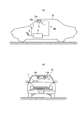
- FIG. 1 is a diagram showing an example in which a device control system according to the embodiment is mounted on a vehicle.
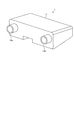
- FIG. 2 is a view showing an example of the appearance of the object recognition apparatus according to the embodiment.
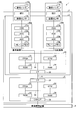
- FIG. 3 is a diagram showing an example of the hardware configuration of the object recognition apparatus according to the embodiment.
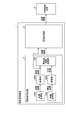
- FIG. 4 is a diagram showing an example of a functional block configuration of the object recognition device according to the embodiment.
- FIG. 5 is a diagram showing an example of a functional block configuration of a disparity value calculation processing unit of the object recognition device according to the embodiment.
- FIG. 6 is a diagram for explaining the principle of deriving the distance from the imaging unit to the object.
- FIG. 1 is a diagram showing an example in which a device control system according to the embodiment is mounted on a vehicle.
- FIG. 2 is a view showing an example of the appearance of the object recognition apparatus according to the embodiment.
- FIG. 3 is a diagram showing an example of the hardware configuration of the object recognition apparatus according to the embodiment.
- FIG. 7 is an explanatory diagram in the case of finding a corresponding pixel in a comparison image corresponding to a reference pixel in a reference image.
- FIG. 8 is a diagram showing an example of a graph of the result of the block matching process.
- FIG. 9 is a diagram showing an example of a functional block configuration of a recognition processing unit of the object recognition device according to the embodiment.
- FIG. 10 is a diagram illustrating an example of a V map generated from a parallax image.
- FIG. 11 is a diagram illustrating an example of a U map generated from a parallax image.
- FIG. 12 is a diagram showing an example of a real U map generated from the U map.
- FIG. 13 is a diagram for explaining the process of extracting an isolated area from the real U map.
- FIG. 10 is a diagram illustrating an example of a V map generated from a parallax image.
- FIG. 11 is a diagram illustrating an example of a U map generated from a par
- FIG. 14 is a diagram for explaining the process of creating a detection frame.
- FIG. 15 is a diagram for explaining the case where the inter-frame distance is short.
- FIG. 16 is a diagram for explaining the case where the inter-frame distance is a long distance.
- FIG. 17 is a flowchart illustrating an example of the block matching process performed by the disparity value deriving unit according to the embodiment.
- FIG. 18 is a flowchart illustrating an example of the operation of the object recognition processing of the recognition processing unit according to the embodiment.
- FIG. 19 is a flowchart illustrating an example of the overlap processing operation of the recognition processing unit according to the embodiment.
- FIG. 20 is a diagram for explaining the overlapping area when the interframe distance is a short distance.
- FIG. 21 is a diagram for explaining an operation of discarding a detected object when the inter-frame distance is short.
- FIG. 22 is a diagram for explaining the overlapping area when the interframe distance is a long distance.
- FIG. 23 is a diagram for explaining the case where the overlapping area does not occur when the inter-frame distance is a long distance.
- FIG. 24 is a diagram for explaining the case where the detected object is not rejected when the inter-frame distance is a long distance.
- FIG. 1 is a diagram showing an example in which a device control system according to the embodiment is mounted on a vehicle. The case where the device control system 60 of the present embodiment is mounted on a vehicle 70 will be described as an example with reference to FIG. 1.
- FIG. 1A is a side view of a vehicle 70 equipped with the device control system 60
- FIG. 1B is a front view of the vehicle 70. As shown in FIG.
- a vehicle 70 which is a car is equipped with a device control system 60.
- the device control system 60 includes an object recognition device 1 installed in a cabin which is a room space of the vehicle 70, a vehicle control device 6 (control device), a steering wheel 7, and a brake pedal 8.
- the object recognition device 1 has an imaging function of imaging the traveling direction of the vehicle 70 and is installed, for example, in the vicinity of a rearview mirror inside a front window of the vehicle 70.
- the object recognition device 1 includes the main body 2, an imaging unit 10 a fixed to the main body 2, and an imaging unit 10 b, the details of the configuration and operation will be described later.
- the imaging units 10 a and 10 b are fixed to the main unit 2 so as to be able to capture an object in the traveling direction of the vehicle 70.
- the vehicle control device 6 is an ECU (Electronic Control Unit) that executes control of various vehicles based on the recognition information received from the object recognition device 1.
- the vehicle control device 6 controls steering system (control target) including the steering wheel 7 based on the recognition information received from the object recognition device 1 as an example of vehicle control, or steering control to avoid an obstacle, or A brake control or the like is performed to control the brake pedal 8 (control target) to decelerate and stop the vehicle 70.
- vehicle safety such as steering control or brake control is performed to improve the driving safety of the vehicle 70. it can.
- the object recognition apparatus 1 shall image the front of the vehicle 70 as mentioned above, it is not limited to this. That is, the object recognition device 1 may be installed to image the rear or side of the vehicle 70. In this case, the object recognition device 1 can detect the position of a succeeding vehicle and a person behind the vehicle 70 or other vehicles and people on the side. Then, the vehicle control device 6 can execute the above-described vehicle control by detecting a danger at the time of lane change of the vehicle 70 or lane merging. Further, in the back operation when the vehicle 70 is parked, etc., the vehicle control device 6 determines that there is a danger of collision based on the recognition information on the obstacle behind the vehicle 70 output by the object recognition device 1 In some cases, the vehicle control described above can be performed.
- FIG. 2 is a view showing an example of the appearance of the object recognition apparatus according to the embodiment.
- the object recognition device 1 includes the main body 2, the imaging unit 10 a fixed to the main body 2, and the imaging unit 10 b as described above.
- the imaging units 10 a and 10 b are configured by a pair of cylindrical cameras arranged in parallel with the main unit 2. Further, for convenience of description, the imaging unit 10a illustrated in FIG. 2 may be referred to as a right camera, and the imaging unit 10b may be referred to as a left camera.
- FIG. 3 is a diagram showing an example of the hardware configuration of the object recognition apparatus according to the embodiment. The hardware configuration of the object recognition device 1 will be described with reference to FIG.
- the object recognition device 1 includes a parallax value deriving unit 3 and a recognition processing unit 5 in the main body unit 2.
- the parallax value deriving unit 3 derives a parallax value dp indicating parallax for the object from a plurality of images obtained by imaging the object, and outputs a parallax image (an example of distance information) indicating the parallax value dp in each pixel Device.
- the recognition processing unit 5 performs an object recognition process or the like on an object such as a person or a car reflected in a captured image based on the parallax image output from the parallax value derivation unit 3, and information indicating the result of the object recognition process It is an apparatus which outputs the recognition information which is these to the vehicle control apparatus 6.
- the parallax value deriving unit 3 includes an imaging unit 10 a, an imaging unit 10 b, a signal conversion unit 20 a, a signal conversion unit 20 b, and an image processing unit 30.
- the imaging unit 10a is a processing unit that images an object in front and generates an analog image signal.
- the imaging unit 10a includes an imaging lens 11a, an aperture 12a, and an image sensor 13a.
- the imaging lens 11a is an optical element for refracting incident light to form an image of an object on the image sensor 13a.
- the diaphragm 12a is a member that adjusts the amount of light input to the image sensor 13a by blocking part of the light that has passed through the imaging lens 11a.
- the image sensor 13a is a semiconductor element which is incident on the imaging lens 11a and converts the light passing through the diaphragm 12a into an electrical analog image signal.
- the image sensor 13a is realized by, for example, a solid-state imaging device such as a charge coupled device (CCD) or a complementary metal oxide semiconductor (CMOS).
- CCD charge coupled device
- CMOS complementary metal oxide semiconductor
- the imaging unit 10 b is a processing unit that captures an image of a subject in front and generates an analog image signal.
- the imaging unit 10 b includes an imaging lens 11 b, an aperture 12 b, and an image sensor 13 b.
- the functions of the imaging lens 11b, the diaphragm 12b, and the image sensor 13b are the same as the functions of the imaging lens 11a, the diaphragm 12a, and the image sensor 13a described above. Further, the imaging lens 11a and the imaging lens 11b are installed such that the main surfaces thereof are on the same plane so that the left and right cameras can be imaged under the same condition.
- the signal conversion unit 20a is a processing unit that converts an analog image signal generated by the imaging unit 10a into digital image data.
- the signal conversion unit 20a includes a CDS (Correlated Double Sampling) 21a, an AGC (Auto Gain Control) 22a, an ADC (Analog Digital Converter) 23a, and a frame memory 24a.
- CDS Correlated Double Sampling
- AGC Auto Gain Control
- ADC Analog Digital Converter
- the CDS 21a removes noise from the analog image signal generated by the image sensor 13a by correlated double sampling, a horizontal differential filter, or a vertical smoothing filter.
- the AGC 22a performs gain control to control the intensity of an analog image signal from which noise has been removed by the CDS 21a.
- the ADC 23a converts an analog image signal whose gain is controlled by the AGC 22a into digital image data.
- the frame memory 24a stores the image data converted by the ADC 23a.
- the signal conversion unit 20 b is a processing unit that converts an analog image signal generated by the imaging unit 10 b into digital image data.
- the signal conversion unit 20 b includes a CDS 21 b, an AGC 22 b, an ADC 23 b, and a frame memory 24 b.
- the functions of the CDS 21b, the AGC 22b, the ADC 23b, and the frame memory 24b are the same as the functions of the CDS 21a, the AGC 22a, the ADC 23a, and the frame memory 24a described above.
- the image processing unit 30 is a device that performs image processing on image data converted by the signal conversion unit 20a and the signal conversion unit 20b.
- the image processing unit 30 includes an FPGA (field programmable gate array) 31, a central processing unit (CPU) 32, a read only memory (ROM) 33, a random access memory (RAM) 34, and an interface (I / F) 35. And a bus line 39.
- FPGA field programmable gate array
- the FPGA 31 is an integrated circuit, and here performs processing of deriving a parallax value dp in an image based on image data.
- the CPU 32 controls each function of the disparity value deriving unit 3.
- the ROM 33 stores an image processing program that the CPU 32 executes to control each function of the disparity value deriving unit 3.
- the RAM 34 is used as a work area of the CPU 32.
- the I / F 35 is an interface for communicating with the I / F 55 in the recognition processing unit 5 and the communication line 4.
- the bus line 39 is, as shown in FIG. 3, an address bus, a data bus, and the like that connect the FPGA 31, the CPU 32, the ROM 33, the RAM 34, and the I / F 35 so that they can communicate with each other.
- the image processing unit 30 includes the FPGA 31 as an integrated circuit for deriving the parallax value dp, the present invention is not limited to this, and an integrated circuit such as an application specific integrated circuit (ASIC) may be used. .
- ASIC application specific integrated circuit
- the recognition processing unit 5 includes an FPGA 51, a CPU 52, a ROM 53, a RAM 54, an I / F 55, a CAN (Controller Area Network) I / F 58, and a bus line 59. .
- the FPGA 51 is an integrated circuit, and here performs object recognition processing on an object based on a parallax image or the like received from the image processing unit 30.
- the CPU 52 controls each function of the recognition processing unit 5.
- the ROM 53 stores a program for object recognition processing in which the CPU 52 executes the object recognition processing of the recognition processing unit 5.
- the RAM 54 is used as a work area of the CPU 52.
- the I / F 55 is an interface for performing data communication with the I / F 35 of the image processing unit 30 and the communication line 4.
- the CAN I / F 58 is an interface for communicating with an external controller (for example, the vehicle control device 6 shown in FIG. 3).
- the FPGA 51, the CPU 52, the ROM 53, the RAM 54, the I / F 55, and the CANI / F 58 are an address bus, a data bus, and the like connected so as to be able to communicate with each other.
- the FPGA 51 converts the parallax image into a parallax image according to an instruction of the CPU 52 in the recognition processing unit 5. Based on the object recognition processing of an object such as a person and a car reflected in a captured image is executed.
- Each of the above programs may be distributed in a computer readable recording medium as an installable or executable file.
- This recording medium is, for example, a compact disc read only memory (CD-ROM) or a secure digital (SD) memory card.
- the image processing unit 30 of the disparity value deriving unit 3 and the recognition processing unit 5 are separate devices, the present invention is not limited to this.
- the image processing unit 30 The parallax image generation and the object recognition processing may be performed using the same device as the recognition processing unit 5 and the recognition processing unit 5.
- FIG. 4 is a diagram showing an example of a functional block configuration of the object recognition device according to the embodiment. First, the configuration and operation of the functional blocks of the main part of the object recognition device 1 will be described with reference to FIG.
- the object recognition device 1 includes the parallax value deriving unit 3 and the recognition processing unit 5.
- the parallax value deriving unit 3 includes an image acquiring unit 100 a (first imaging unit), an image acquiring unit 100 b (second imaging unit), conversion units 200 a and 200 b, and a parallax value arithmetic processing unit 300 (generation unit And.
- the image acquisition unit 100a is a functional unit that captures an object in front with the right camera, generates an analog image signal, and obtains a luminance image that is an image based on the image signal.
- the image acquisition unit 100a is realized by the imaging unit 10a illustrated in FIG.
- the image acquisition unit 100 b is a functional unit that captures an object in front with the left camera, generates an analog image signal, and obtains a luminance image that is an image based on the image signal.
- the image acquisition unit 100b is realized by the imaging unit 10b illustrated in FIG.
- the conversion unit 200a is a functional unit that removes noise from the image data of the luminance image obtained by the image acquisition unit 100a, converts the image data into digital image data, and outputs the image data.
- the converter 200a is realized by the signal converter 20a shown in FIG.
- the conversion unit 200b is a functional unit that removes noise from the image data of the luminance image obtained by the image acquisition unit 100b, converts the image data into digital image data, and outputs the image data.
- the converter 200b is realized by the signal converter 20b shown in FIG.
- the luminances captured by the image acquisition unit 100a that is the right camera (the imaging unit 10a) The image is used as the image data of the reference image Ia (hereinafter simply referred to as the reference image Ia) (first captured image), and the luminance image captured by the image acquisition unit 100b which is the left camera (imaging unit 10b) is compared with the image Image data of Ib (hereinafter, simply referred to as comparison image Ib) (second captured image). That is, the conversion units 200a and 200b output the reference image Ia and the comparison image Ib, respectively, based on the two luminance images output from the image acquisition units 100a and 100b.
- the parallax value calculation processing unit 300 derives the parallax value dp for each pixel of the reference image Ia based on the reference image Ia and the comparison image Ib received from each of the conversion units 200a and 200b, and sets each pixel of the reference image Ia. It is a functional unit that generates a parallax image corresponding to the parallax value dp.
- the disparity value calculation processing unit 300 outputs the generated disparity image to the recognition processing unit 5.
- the recognition processing unit 5 is a functional unit that recognizes (detects) an object based on the reference image Ia and the parallax image received from the parallax value derivation unit 3 and performs tracking processing on the recognized object. is there.
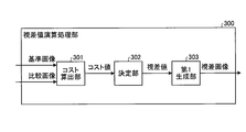
- FIG. 5 is a diagram showing an example of a functional block configuration of a disparity value calculation processing unit of the object recognition device according to the embodiment.
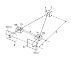
- FIG. 6 is a diagram for explaining the principle of deriving the distance from the imaging unit to the object.
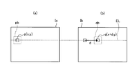
- FIG. 7 is an explanatory diagram in the case of finding a corresponding pixel in a comparison image corresponding to a reference pixel in a reference image.
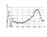
- FIG. 8 is a diagram showing an example of a graph of the result of the block matching process.
- the imaging system shown in FIG. 6 is assumed to have an imaging unit 10a and an imaging unit 10b arranged in parallel equilibria.
- the imaging units 10a and 10b respectively include imaging lenses 11a and 11b that refract incident light to form an image of an object on an image sensor that is a solid-state imaging device.
- the images captured by the imaging unit 10a and the imaging unit 10b are respectively referred to as a reference image Ia and a comparison image Ib.
- a point S on the object E in a three-dimensional space is mapped at a position on a straight line parallel to a straight line connecting the imaging lens 11a and the imaging lens 11b in each of the reference image Ia and the comparison image Ib.
- a point S mapped to each image is taken as a point Sa (x, y) in the reference image Ia, and taken as a point Sb (X, y) in the comparison image Ib.
- the parallax value dp is given by the following (formula 1) Is represented by
- the distance between the point Sa (x, y) in the reference image Ia and the intersection of the perpendicular drawn from the imaging lens 11a onto the imaging surface is ⁇ a
- the distance Z between the imaging units 10a and 10b and the object E is derived by using the parallax value dp.
- the distance Z is a distance from a straight line connecting the focal position of the imaging lens 11a and the focal position of the imaging lens 11b to the point S on the object E.
- the distance Z can be calculated by 2).
- C (p, d) A method of calculating the cost value C (p, d) will be described with reference to FIGS. 7 and 8.
- C (p, d) will be described as representing C (x, y, d).
- FIG. 7A shows a conceptual diagram showing the reference pixel p and the reference area pb in the reference image Ia
- FIG. 7B corresponds to the reference pixel p shown in FIG. 7A.
- the corresponding pixel indicates a pixel in the comparison image Ib most similar to the reference pixel p in the reference image Ia.
- the cost value C is an evaluation value (coincidence) indicating the similarity or dissimilarity of each pixel in the comparison image Ib with respect to the reference pixel p in the reference image Ia.
- the cost value C shown below is described as an evaluation value representing a dissimilarity indicating that the pixel in the comparison image Ib is similar to the reference pixel p as the value is smaller.
- candidates for corresponding pixels on the epipolar line EL in the comparison image Ib with respect to the reference pixel p (x, y) in the reference image Ia and the reference pixel p (x, y) are candidates.
- d is the shift amount (shift amount) between the reference pixel p and the candidate pixel q, and the shift amount d is shifted in pixel units.
- the candidate pixel q (x + d, y) and the reference pixel p (x, y) are sequentially shifted while sequentially shifting the candidate pixel q (x + d, y) by one pixel in a predetermined range (for example, 0 ⁇ d ⁇ 25).
- Cost value C (p, d) which is the dissimilarity of the luminance value with.
- block matching processing is performed as stereo matching processing in order to obtain a corresponding pixel of the reference pixel p.
- a reference area pb which is a predetermined area centered on the reference pixel p of the reference image Ia, and a candidate area qb centered on the candidate pixel q of the comparison image Ib (the size is the same as the reference area pb).
- the average value of each block is subtracted from the value of SAD (Sum of Absolute Difference), SSD (Sum of Squared Difference), or SSD.
- ZSSD Zero-mean-Sum of Squared Difference
- the reference image Ia and the comparison image Ib also have parallel equidistant relationships. Therefore, the corresponding pixel in the comparison image Ib corresponding to the reference pixel p in the reference image Ia is present on the epipolar line EL shown as a line in the lateral direction of the drawing in FIG. In order to obtain it, the pixels on the epipolar line EL of the comparison image Ib may be searched.
- the cost value C (p, d) calculated by such block matching processing is represented by, for example, a graph shown in FIG. 8 in relation to the shift amount d.
- the disparity value calculation processing unit 300 includes a cost calculation unit 301, a determination unit 302, and a first generation unit 303.
- the cost calculation unit 301 determines the luminance value of the reference pixel p (x, y) in the reference image Ia and the reference pixel p (x, x) on the epipolar line EL in the comparison image Ib based on the reference pixel p (x, y).
- Each candidate pixel q (x + d, y) is identified based on each luminance value of candidate pixel q (x + d, y), which is a candidate for the corresponding pixel, identified by shifting from the pixel corresponding to the position y) by the shift amount d. It is a functional unit that calculates the cost value C (p, d) of y).
- the cost calculation unit 301 performs block matching processing on a reference area pb which is a predetermined area centered on the reference pixel p of the reference image Ia and a candidate area qb centered on the candidate pixel q of the comparison image Ib.
- the degree of dissimilarity with (the size is the same as that of the reference area pb) is calculated as the cost value C.
- the determination unit 302 determines the shift amount d corresponding to the minimum value of the cost value C calculated by the cost calculation unit 301 as the parallax value dp for the pixel of the reference image Ia which is the target of the calculation of the cost value C. It is a functional unit.
- the first generation unit 303 generates a parallax image which is an image in which the pixel value of each pixel of the reference image Ia is replaced with the parallax value dp corresponding to the pixel based on the parallax value dp determined by the determination unit 302 Functional unit.
- the cost calculation unit 301, the determination unit 302, and the first generation unit 303 shown in FIG. 5 are each realized by the FPGA 31 shown in FIG. Note that some or all of the cost calculation unit 301, the determination unit 302, and the first generation unit 303 are realized by the CPU 32 executing a program stored in the ROM 33 instead of the FPGA 31, which is a hardware circuit. It is good also as things.
- the cost calculation unit 301, the determination unit 302, and the first generation unit 303 of the disparity value calculation processing unit 300 shown in FIG. 5 conceptually show the functions, and are limited to such a configuration. is not.
- a plurality of functional units illustrated as independent functional units in the parallax value calculation processing unit 300 illustrated in FIG. 5 may be configured as one functional unit.
- the parallax value arithmetic processing unit 300 illustrated in FIG. 5 may divide the function of one functional unit into a plurality of units and configure the plurality of functional units.
- FIG. 9 is a diagram showing an example of a functional block configuration of a recognition processing unit of the object recognition device according to the embodiment.
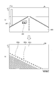
- FIG. 10 is a diagram illustrating an example of a V map generated from a parallax image.
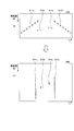
- FIG. 11 is a diagram illustrating an example of a U map generated from a parallax image.
- FIG. 12 is a diagram showing an example of a real U map generated from the U map.
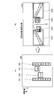
- FIG. 13 is a diagram for explaining the process of extracting an isolated area from the real U map.
- FIG. 14 is a diagram for explaining the process of creating a detection frame.
- FIG. 15 is a diagram for explaining the case where the inter-frame distance is short.
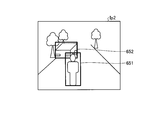
- FIG. 16 is a diagram for explaining the case where the inter-frame distance is a long distance.
- the recognition processing unit 5 includes a second generation unit 501, a clustering processing unit 502, and a tracking unit 503.
- the second generation unit 501 receives the parallax image from the parallax value calculation processing unit 300, and receives the reference image Ia from the parallax value derivation unit 3, and generates a V-Disparity map, a U-Disparity map, and a Real U-Disparity. It is a functional unit that generates maps and the like. Specifically, the second generation unit 501 generates a V map VM, which is a V-Disparity map shown in FIG. 10B, in order to detect the road surface from the parallax image input from the parallax value calculation processing unit 300. .
- the V-Disparity map is a two-dimensional histogram showing the frequency distribution of the parallax value dp, with the vertical axis as the y-axis of the reference image Ia and the horizontal axis as the parallax value dp (or distance) of the parallax image.
- a road surface 600, a telephone pole 601, and a car 602 are reflected.
- the road surface 600 of the reference image Ia corresponds to the road surface portion 600a in the V map VM
- the electric pole 601 corresponds to the electric pole portion 601a
- the car 602 corresponds to the car portion 602a.
- the second generation unit 501 linearly approximates the position estimated to be a road surface from the generated V map VM.
- the road surface is flat, it can be approximated by one straight line, but in the case of a road surface where the slope changes, it is necessary to divide the section of the V map VM and perform linear approximation with high accuracy.
- the linear approximation the Hough transform or the least squares method, which is a known technique, can be used.
- the electric pole portion 601a and the car portion 602a which are blocks located above the detected road surface portion 600a correspond to the electric pole 601 and the car 602 which are objects on the road surface 600, respectively.
- the second generation unit 501 uses only the information located above the road surface detected by the V map VM, that is, the left guard rail 611, the right guard rail 612, and the car 613 in the reference image Ia shown in FIG. And, in order to recognize an object using information on the parallax image corresponding to the car 614, a U map UM which is a U-Disparity map shown in FIG. 11B is generated.
- the U map UM is a two-dimensional histogram showing the frequency distribution of the parallax values dp, with the horizontal axis as the x axis of the reference image Ia and the vertical axis as the parallax values dp (or distance) of parallax images.
- the left guardrail 611 of the reference image Ia shown in FIG. 11A corresponds to the left guardrail 611a in the U map UM
- the right guardrail 612 corresponds to the right guardrail 612a
- the car 613 corresponds to the car 613a
- the car 614 corresponds to the car portion 614a.
- the second generation unit 501 uses only the information located above the road surface detected by the V map VM, that is, the left guard rail 611, the right guard rail 612, and the car 613 in the reference image Ia shown in FIG. And information on the parallax image corresponding to the car 614 is used to generate a U map UM_H which is an example of the U-Disparity map shown in FIG.
- a U map UM_H which is an example of the U-Disparity map is an image in which the horizontal axis is the x axis of the reference image Ia, the vertical axis is the parallax value dp of the parallax image, and the pixel value is the height of the object.
- the left guard rail 611 of the reference image Ia shown in FIG. 11A corresponds to the left guard rail portion 611 b in U map UM_H
- the right guard rail 612 corresponds to the right guard rail portion 612 b
- the car 613 corresponds to the car portion 613 b
- the car 614 corresponds to the car portion 614 b.
- the second generation unit 501 is a real U map RM which is a Real U-Disparity map shown in FIG. 12 (b) obtained by converting the horizontal axis into an actual distance from the generated U map UM shown in FIG. 12 (a).
- the horizontal axis is the actual distance in the direction from the imaging unit 10b (left camera) to the imaging unit 10a (right camera)
- the vertical axis is the parallax value dp of parallax images (or It is a two-dimensional histogram which is a distance in the depth direction converted from the parallax value dp.
- the second generation unit 501 does not thin out the parallax information because the object is small at a distance (the parallax value dp is small) and the parallax information is small and the resolution of the distance is small.
- a real U map RM corresponding to an overhead view is generated.
- an object can be detected by extracting a block (object) of pixel values (an “isolated region” described later) from the real U map RM.
- the width of the rectangle surrounding the block corresponds to the width of the extracted object
- the height corresponds to the depth of the extracted object.
- the second generation unit 501 is not limited to the generation of the real U map RM from the U map UM, and can also generate the real U map RM directly from parallax images.
- the image input from the parallax value derivation unit 3 to the second generation unit 501 is not limited to the reference image Ia, and the comparison image Ib may be used as a target.
- the second generation unit 501 is realized by the FPGA 51 shown in FIG.
- the second generation unit 501 may be realized by the CPU 52 executing a program stored in the ROM 53 instead of the FPGA 51 which is a hardware circuit.
- the clustering processing unit 502 is a functional unit that performs clustering processing for detecting an object appearing in a parallax image based on each map output from the second generation unit 501. As illustrated in FIG. 9, the clustering processing unit 502 includes an area extracting unit 511 (extracting unit), a frame creating unit 512 (determining unit), a first rejection unit 513, and an overlap processing unit 514.
- the area extraction unit 511 is a functional unit that extracts an isolated area that is a block of pixel values from the real U map RM among the maps (images) output from the second generation unit 501. Specifically, the region extraction unit 511 performs binarization processing, labeling processing, and the like on the real U map RM, and extracts an isolated region for each piece of identification information of the labeling processing. For example, FIG. 13 shows a state in which an isolated area is extracted in the real U map RM. The example of the real U map RM shown in FIG. 13 shows the case where the isolated regions 621 to 624 are extracted as isolated regions by the region extraction unit 511.
- the isolated area extracted by the area extraction unit 511 corresponds to the object appearing in the reference image Ia, and indicates the recognition area of the object in the reference image Ia.
- the region extraction unit 511 determines the position and width in the x-axis direction of the parallax image of the object in the isolated region and the reference image Ia from the U map UM or real U map RM generated by the second generation unit 501 (x min, x max Can be identified.
- the region extraction unit 511 can specify the actual depth of the object from the information (dmin, dmax) of the height of the object in the U map UM or the real U map RM.
- the region extraction unit 511 calculates the actual value of the object from the width (xmin, xmax) in the x-axis direction, the height (ymin, ymax) in the y-axis direction of the object specified in the parallax image and the parallax value dp corresponding to each.
- the size in the x-axis direction and the y-axis direction can be identified.
- the region extraction unit 511 uses the V map VM, the U map UM, and the real U map RM to determine the position of the isolated region object and the actual width, height, and depth in the reference image Ia. It can be identified.
- the region extraction unit 511 can also determine the position in the parallax image and can specify the distance to the object.
- the area extraction unit 511 generates recognition area information, which is information on the isolated area, for each of the extracted isolated areas, and here, for example, identification information of the labeling process and the reference image Ia, V map VM, U map Information on the position and size of the isolated area on the UM and the real U map RM is included in the recognition area information.
- the area extraction unit 511 sends the generated recognition area information to the frame generation unit 512.
- the region extraction unit 511 performs smoothing on the extracted isolated region to reduce noise, parallax dispersion, and the like present on the real U map RM, surface detection of an object in the isolated region, or deletion of unnecessary regions. Or the like may be performed.
- the frame creating unit 512 refers to an area of the object corresponding to the isolated area in the parallax image Ip (or the reference image Ia) with respect to the isolated area of the object in the real U map RM extracted by the area extracting unit 511 It is a functional unit that creates a frame in Specifically, as shown in FIG. 14A, the frame creating unit 512 sets detection regions 631 to 634 corresponding to the isolated regions 621 to 624 extracted by the region extraction unit 511 on the real U map RM. In a corresponding manner, detection frames 631a to 634a are created on the parallax image Ip or the reference image Ia, respectively, as shown in FIG. 14 (b).
- the frame creating unit 512 includes information of a frame created by the parallax image Ip or the reference image Ia in the recognition area information and sends the recognition region information to the first discarding unit 513.
- the first rejection unit 513 determines the actual size (width, height, depth) of an object in the detection area (hereinafter, may be referred to as a detection object) from the size of the detection area indicated by the frame by the frame generation unit 512. Is a functional unit that identifies what the object is from and discards according to the type of the object.
- the first rejection unit 513 specifies what the detected object is, for example, using (Table 1) below. For example, if the width of the object is 1300 mm, the height is 1800 mm, and the depth is 2000 mm, the object can be identified as a “normal vehicle” vehicle.
- the information that associates the width, height and depth as shown in Table 1 with the type of the object (object type) may be stored as a table in the RAM 54 or the like. Further, the relationship between the size shown in (Table 1) and the type of object (object type) is an example, and may be defined by the relationship between other sizes and types of object.
- the first discarding unit 513 discards the object determined to be excluded from the target of the processing of the latter stage (such as overlap processing and tracking processing described later) according to the type of the detected object identified. For example, when the pedestrian (person) and the vehicle are targets of the subsequent processing, the first rejection unit 513 is a side wall object (guard rail) indicated by the detection frames 631a and 632a illustrated in FIG. Therefore, we reject these.
- the first discarding unit 513 includes, for example, a flag (rejection flag) indicating rejection in the recognition area information of the detected object. The first discarding unit 513 determines whether or not to reject the detected object according to the type of the detected object identified.
- the present invention is not limited to this, and the size of the detection area is not limited to this. It may be determined based on whether or not the object in the detection area is to be rejected.
- the first rejection unit 513 includes a rejection flag indicating whether or not to discard the detected object in the recognition area information, and sends the recognition region information to the overlap processing unit 514. In the following description of overlap processing and tracking processing, it is assumed that the rejection flag included in the recognition area information of the detected object is OFF, that is, it is not rejected.
- the overlap processing unit 514 has a function of performing an overlap process to determine whether or not to reject an object in these detection areas based on the area where these detection areas overlap. It is a department.
- the overlap processing unit 514 includes a first determination unit 521, a distance calculation unit 522 (first calculation unit), a second determination unit 523 (determination unit), and an overlapping area calculation unit 524 (second calculation unit).
- a third determination unit 525 and a second rejection unit 526 (rejection means) are included.
- the first determination unit 521 is a functional unit that determines whether or not two detection areas overlap.
- the distance calculation unit 522 calculates the distance in the depth direction between the objects of the overlapping detection areas (hereinafter may be referred to as an interframe distance). Functional unit.
- the second determination unit 523 is a functional unit that determines whether the inter-frame distance calculated by the distance calculation unit 522 is less than a predetermined threshold.
- a distance greater than a predetermined threshold is referred to as a “far distance” (second distance range)
- a distance less than the predetermined threshold is referred to as a “short distance” (first distance range).
- the second determination unit 523 switches a predetermined threshold value to be compared with the inter-frame distance, for example, as shown in (Table 2) below, according to the distance to the near object of the two detected objects.
- the second determination unit 523 compares the distance with the inter-frame distance when the distance to the near object of the two detected objects is 15 [m] or more and less than 35 [m].
- the predetermined threshold is set to 4.5 [m].
- the relationship between the distance of the detected object shown in (Table 2) and the threshold value to be compared with the distance between the frames is an example, and may be defined by another relationship. Details of the determination processing by the second determination unit 523 will be described later with reference to FIG.
- FIG. 15 shows an example where the inter-frame distance is short.
- a detection area 641 in which the detected object is a pedestrian and a detection area 642 in which the detected object is a vehicle are near and a part of each of the detection areas 641 and 642 is It is shown that they overlap.
- FIG. 16 shows an example where the inter-frame distance is far.
- the detection area 651 in which the detection object is a pedestrian and the detection area 652 in which the detection object is a vehicle are at a long distance, and each of the detection areas 651 and 652 is It is shown that they overlap.
- the overlapping area calculation unit 524 is a functional unit that calculates the area of a portion where two detection areas overlap (hereinafter, may be referred to as an overlapping area). Details of the calculation process of the overlap area by the overlap area calculation unit 524 will be described later with reference to FIGS. 19, 20, 22 and 23.
- the third determination unit 525 determines whether the overlapping area calculated by the overlapping area calculation unit 524 is larger than a predetermined ratio of one of the two detection areas (a threshold value for the overlapping ratio of detection areas). It is a functional unit that determines whether the Here, the third determination unit 525 switches a predetermined ratio (threshold value) as shown in (Table 3) below, for example, according to whether the inter-frame distance between the two detection areas is a short distance or a long distance. . For example, as shown in (Table 3), when the inter-frame distance between two detection areas is a long distance, the third determination unit 525 sets the threshold for the overlap ratio of the detection areas to any one of the two detection areas. Or 15% of one of the areas.
- the relationship between the interframe distance shown in (Table 3) and the threshold value for the overlap ratio of the detection area is an example, and may be defined by other relationships. Details of the determination processing by the third determination unit 525 will be described later with reference to FIG.
- the second rejection unit 526 is a functional unit that determines whether or not to reject an object in two detection areas according to the determination result on the size of the overlapping area by the third determination unit 525.
- the second rejection unit 526 includes a rejection flag indicating whether or not the detected object is to be rejected in the recognition area information, and sends the recognition region information to the tracking unit 503. Details of the rejection processing by the second rejection unit 526 will be described later with reference to FIG.
- the area calculation unit 524, the third determination unit 525, and the second rejection unit 526 are each realized by the FPGA 51 shown in FIG.
- Some or all of the unit 524, the third determination unit 525, and the second rejection unit 526 are realized as a result that the program stored in the ROM 53 is executed by the CPU 52 instead of the FPGA 51 which is a hardware circuit. It is also good.
- the tracking unit 503 is a functional unit that executes tracking processing for tracking the detected object whose rejection flag is OFF, based on the recognition area information that is information on the object detected by the clustering processing unit 502.
- the tracking unit 503 outputs recognition area information including the result of the tracking process to the vehicle control device 6 (see FIG. 3) as recognition information.
- the tracking unit 503 is realized by the FPGA 51 shown in FIG.
- the tracking unit 503 may be realized by the CPU 52 executing a program stored in the ROM 53 instead of the FPGA 51 which is a hardware circuit.
- the “image processing apparatus” may be the clustering processing unit 502 or may be the recognition processing unit 5 including the clustering processing unit 502.
- each functional unit of the recognition processing unit 5 shown in FIG. 9 conceptually shows a function, and is not limited to such a configuration.
- a plurality of functional units illustrated as independent functional units in the recognition processing unit 5 illustrated in FIG. 9 may be configured as one functional unit.
- the function of one functional unit may be divided into a plurality of parts by the recognition processing unit 5 shown in FIG. 9 and configured as a plurality of functional units.
- FIG. 17 is a flowchart illustrating an example of the block matching process performed by the disparity value deriving unit according to the embodiment. The flow of the block matching process of the disparity value deriving unit 3 of the object recognition device 1 will be described with reference to FIG.
- Step S1-1 The image acquiring unit 100b of the parallax value deriving unit 3 captures an object in front with the left camera (imaging unit 10b), generates an analog image signal, and obtains a luminance image that is an image based on the image signal. . As a result, an image signal to be subjected to image processing in the subsequent stage can be obtained. Then, the process proceeds to step S2-1.
- Step S1-2> The image acquiring unit 100a of the parallax value deriving unit 3 captures an object in front with the right camera (imaging unit 10a), generates an analog image signal, and obtains a luminance image that is an image based on the image signal. . As a result, an image signal to be subjected to image processing in the subsequent stage can be obtained. Then, the process proceeds to step S2-2.
- Step S2-1> The conversion unit 200b of the parallax value derivation unit 3 removes noise from the analog image signal obtained by imaging by the imaging unit 10b and converts the signal into digital image data. As described above, by converting into image data of digital format, image processing for each pixel can be performed on an image based on the image data. Then, the process proceeds to step S3-1.
- Step S2-2> The conversion unit 200a of the parallax value derivation unit 3 removes noise from the analog image signal obtained by imaging by the imaging unit 10a, and converts it into digital image data. As described above, by converting into image data of digital format, image processing for each pixel can be performed on an image based on the image data. Then, the process proceeds to step S3-2.
- Step S3-1 The conversion unit 200b outputs an image based on the digital format image data converted in step S2-1 as a comparison image Ib in the block matching process. As a result, an image to be compared to obtain a parallax value in the block matching process is obtained. Then, the process proceeds to step S4.
- Step S3-2> The conversion unit 200a outputs an image based on the digital format image data converted in step S2-2 as a reference image Ia in the block matching process. As a result, an image serving as a reference for determining the parallax value in the block matching process is obtained. Then, the process proceeds to step S4.
- the cost calculation unit 301 of the disparity value calculation processing unit 300 of the disparity value derivation unit 3 compares the luminance value of the reference pixel p (x, y) in the reference image Ia and the comparison image Ib based on the reference pixel p (x, y). For each luminance value of the candidate pixel q (x + d, y) of the corresponding pixel, specified by shifting from the pixel corresponding to the position of the reference pixel p (x, y) by the shift amount d on the epipolar line EL in Based on this, the cost value C (p, d) of each candidate pixel q (x + d, y) is obtained by calculation.
- the cost calculation unit 301 performs block matching processing on a reference area pb which is a predetermined area centered on the reference pixel p of the reference image Ia and a candidate area qb centered on the candidate pixel q of the comparison image Ib.
- the degree of dissimilarity with (the size is the same as that of the reference area pb) is calculated as the cost value C. Then, the process proceeds to step S5.
- Step S5> The determination unit 302 of the disparity value calculation processing unit 300 of the disparity value derivation unit 3 has made the shift amount d corresponding to the minimum value of the cost value C calculated by the cost calculation unit 301 the target of the calculation of the cost value C.
- the parallax value dp for the pixels of the reference image Ia is determined.
- the first generation unit 303 of the parallax value calculation processing unit 300 of the parallax value derivation unit 3 sets the luminance value of each pixel of the reference image Ia to that pixel based on the parallax value dp determined by the determination unit 302.
- a parallax image that is an image represented by the corresponding parallax value dp is generated.
- the first generation unit 303 outputs the generated parallax image to the recognition processing unit 5.
- the present invention is not limited to this and may be processing using a SGM (Semi-Global Matching) method.
- SGM Semi-Global Matching
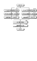
- FIG. 18 is a flowchart illustrating an example of the operation of the object recognition processing of the recognition processing unit according to the embodiment.
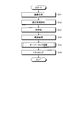
- FIG. 19 is a flowchart illustrating an example of the overlap processing operation of the recognition processing unit according to the embodiment.
- FIG. 20 is a diagram for explaining the overlapping area when the interframe distance is a short distance.
- FIG. 21 is a diagram for explaining an operation of discarding a detected object when the inter-frame distance is short.
- FIG. 22 is a diagram for explaining the overlapping area when the interframe distance is a long distance.
- FIG. 23 is a diagram for explaining the case where the overlapping area does not occur when the inter-frame distance is a long distance.
- FIG. 24 is a diagram for explaining the case where the detected object is not rejected when the inter-frame distance is a long distance.
- the flow of the object recognition process of the recognition processing unit 5 of the object recognition device 1 will be described with reference to FIGS. 18 to 24.
- the second generation unit 501 receives the parallax image Ip from the parallax value calculation processing unit 300, and receives the reference image Ia from the parallax value derivation unit 3, and the V map VM, U map UM, U map UM_H, and real Generate various images of U map RM. Then, the process proceeds to step S12.
- the area extraction unit 511 of the clustering processing unit 502 extracts an isolated area which is a block of pixel values from the real U map RM among the maps (images) output from the second generation unit 501.
- the region extraction unit 511 uses the V map VM, the U map UM and the real U map RM to position the object in the isolated region and the actual width, height, and depth in the reference image Ia or the parallax image Ip.
- the area extraction unit 511 generates recognition area information that is information related to the isolated area for each extracted isolated area, and here, for example, identification information of the labeling process, the reference image Ia, the V map VM, Information on the position and size of the isolated area on the U map UM and the real U map RM is included in the recognition area information.
- the area extraction unit 511 sends the generated recognition area information to the frame generation unit 512. Then, the process proceeds to step S13.
- the frame creating unit 512 of the clustering processing unit 502 detects the detection region of the object corresponding to the isolated region in the parallax image Ip (or the reference image Ia) for the isolated region of the object on the real U map RM extracted by the region extracting unit 511 Is a functional unit that creates a frame.
- the frame creating unit 512 includes information of a frame created by the parallax image Ip or the reference image Ia in the recognition area information and sends the recognition region information to the first discarding unit 513. Then, the process proceeds to step S14.
- the first rejection unit 513 of the clustering processing unit 502 determines what the object is from the actual size (width, height, depth) of the detection object in the detection region from the size of the detection region indicated by the frame by the frame generation unit 512 Identify if there is, and reject according to the type of object.
- the first discarding unit 513 includes, for example, a flag (rejection flag) indicating rejection in the recognition area information of the detected object.
- the first rejection unit 513 includes a rejection flag indicating whether or not to discard the detected object in the recognition area information, and sends the recognition region information to the overlap processing unit 514. Then, the process proceeds to step S15.
- the overlap processing unit 514 performs overlap processing to determine whether or not to discard an object in the detection areas based on the area where the detection areas overlap.
- the overlap processing by the overlap processing unit 514 will be described with reference to FIG.
- Step S151 The first determination unit 521 of the overlap processing unit 514 specifies arbitrary two detection objects among detection objects corresponding to the recognition area information received from the first rejection unit 513. Then, the process proceeds to step S152.
- Step S152 The first determination unit 521 determines whether the detection areas of the two specified detection objects overlap with each other. If the two detection areas overlap (step S152: Yes), the process proceeds to step S153. If the two detection areas do not overlap (step S152: No), the process returns to step S151, and the first determination unit 521 detects two different detection objects. Identify
- Step S153 If the first determination unit 521 determines that the detection areas overlap, the distance calculation unit 522 of the overlap processing unit 514 calculates an inter-frame distance in the depth direction between objects of the overlapping detection areas. Then, the process proceeds to step S154.
- Step S154 The second determination unit 523 of the overlap processing unit 514 determines whether the inter-frame distance calculated by the distance calculation unit 522 is less than a predetermined threshold. If the interframe distance is less than the predetermined threshold, that is, if the interframe distance is close (step S154: Yes), the process proceeds to step S155, and if it is larger than the predetermined threshold, that is, the interframe distance is far When it is (step S154: No), it transfers to step S159.
- Step S 155 When the second determination unit 523 determines that the inter-frame distance is a short distance, the overlap area calculation unit 524 of the overlap processing unit 514 calculates an overlap area of a portion where two detection areas overlap. For example, as shown in FIG. 20, when the detection area 661 and the detection area 662 overlap, the overlapping area calculation unit 524 sets the area of the overlapping area 663 which is the overlapping area to (height OL_H) ⁇ (width) Calculated by OL_W). Then, the process proceeds to step S156.
- Step S156 The third determination unit 525 of the overlap processing unit 514 determines that the overlap area calculated by the overlap area calculation unit 524 is a predetermined ratio of one of the two detection areas (a threshold value for the overlap ratio of the detection areas). It is determined whether or not it is larger than. If the overlapping area is larger than the predetermined ratio of one of the two detection areas (step S156: Yes), the process proceeds to step S157, and if the predetermined ratio is also smaller (step S156: No), It transfers to step S158.
- a predetermined ratio of one of the two detection areas a threshold value for the overlap ratio of the detection areas
- Step S 157 When the two detected objects are both vehicles, the second discarding unit 526 of the overlap processing unit 514 does not reject the detected object having a higher distance of high importance as an object of the tracking processing, and the second discarding unit 526 of the longer processing distance Discard detected objects.
- the second rejection unit 526 includes a rejection flag indicating that rejection is not performed in the recognition region information of the detected object at a shorter distance, and a rejection flag indicating rejection in the recognition region information of the detection object at a longer distance. And to the tracking unit 503.
- the second discarding unit 526 does not reject the detected object, which is a vehicle, But discards the detected object smaller in size than the vehicle.
- a detected object which is not a vehicle and which is smaller than the vehicle is, for example, rejected because it is highly likely that a part of the vehicle is erroneously detected as a pedestrian.
- the second discarding unit 526 has a short distance between the detection area indicated by the detection frame 671 and the detection area indicated by the detection frame 672, and the detected object indicated by the detection frame 671.
- the second rejection unit 526 includes a rejection flag indicating that the vehicle is not rejected, in the recognition area information of the detected object which is a vehicle, and includes a rejection flag indicating that the object is not vehicle, in the recognition area information. Send to section 503.
- Step S158 When it is determined by the third determination unit 525 that the overlapping area is smaller than the predetermined ratio of the area of either one of the two detection areas, the second rejection unit 526 performs tracking processing on objects in any of the detection areas. It is judged that the degree of importance is high as the target of, and any detected objects are not rejected. The second rejection unit 526 transmits a recognition flag indicating that the rejection is not to be included in the recognition area information of each of the two detected objects, to the tracking unit 503.
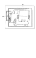
- Step S159 When the second determination unit 523 determines that the inter-frame distance is a long distance, the overlapping area calculation unit 524 determines that the center region (one example of the partial region of the detection region in which the detection object is closer) of the two detection regions. Calculate). Specifically, as shown in FIG. 22, the overlapping area calculation unit 524 sets, for example, a central area in the left-right direction (for example, the left-right direction) for the detection area 681 closer to the detection object The central area 681a which is an area of 80 [%] of the width of 2 is calculated.
- the overlapping area calculation unit 524 calculates the central area of the detection area closer to the detection object
- the present invention is not limited to this, and for example, a predetermined ratio (for example, 85) from the right end of the detection area The area of [%] may be calculated. Then, the process proceeds to step S160.
- Step S160 The overlapping area calculation unit 524 calculates an overlapping area of a portion of the two detection areas in which the central area of the detection area closer to the detected object and the detection area farther to the detected object overlap. For example, as shown in FIG. 22, when the central area 681a of the detection area 681 and the detection area 682 overlap, the overlapping area calculation unit 524 sets the area of the overlapping area 683 which is the overlapping area to (high Calculated by: OL_H1 ⁇ (width OL_W1). Then, the process proceeds to step S161.
- Step S161 The third determination unit 525 determines that the overlap area calculated by the overlap area calculation unit 524 is one of the central area of the detection area closer to the detected object and the detection area farther to the detected object. It is determined whether or not it is larger than the ratio (the threshold for the overlap rate). If the overlapping area is larger than the predetermined ratio of one of the areas (step S161: Yes), the process proceeds to step S162. If the predetermined ratio is smaller than the predetermined area (step S161: No), the process proceeds to step S163.
- the second discarding unit 526 does not reject the detected object having a shorter distance of high importance as an object of tracking processing among the two detected objects, but rejects the detected object having a longer distance.
- the detection area of the closer one is Instead of discarding the detected object of 681, the detected object of the detection area 682 which is farther is discarded.
- the second rejection unit 526 includes a rejection flag indicating that rejection is not performed in the recognition region information of the detected object at a shorter distance, and a rejection flag indicating rejection in the recognition region information of the detection object at a longer distance. And to the tracking unit 503.
- the second discarding unit 526 is controlled by the third determining unit 525 based on a predetermined ratio of the area of either one of the central area of the detection area closer to the detected object and the detection area farther to the detected object. If it is determined that the size of the object is also small, it is determined that the object in any of the detection areas is highly important as the target of the tracking processing, and no detected object is rejected. That is, when it is determined that the overlapping area of the two detection areas is simply larger than a predetermined ratio of the area of one of the two detection areas, the detection object having the longer distance is rejected. Because the overlapping area of the central area of the detection area with the shorter distance is determined, detection should not be performed for the detection area where the overlapping distance at the end is longer. It is possible to suppress that an object (for example, a pedestrian) is rejected.
- the second rejection unit 526 transmits a recognition flag indicating that the rejection is not to be included in the recognition area information of each of the two detected objects, to the tracking unit 503.
- the two detection areas 681 and 682a overlap, but the central area 681a of the detection area 681 and the detection area 682a do not overlap. It is determined that the area is smaller than a predetermined ratio of the area of either one of the central area of the detection area closer to the detection object and the detection area farther to the detection object. In this case, the second discarding unit 526 determines that any of the detection objects in the detection regions 681 and 682a has a high degree of importance as a target of tracking processing, and neither of the detection objects is rejected.
- the second discarding unit 526 has a long distance between the detection area indicated by the detection frame 691 and the detection area indicated by the detection frame 692, and the third judging unit 525. It is determined that the overlapping area is smaller than the predetermined ratio of the area of the central area of the detection area of the detection frame 691 closer to the detected object and the detection area of the detection frame 692 farther to the detected object If it is detected, the detected object indicated by both of the detection frames 691 and 692 is not rejected.
- step S157, S158, S162 or S163 After the process of step S157, S158, S162 or S163 is completed, the process proceeds to step S16.
- the tracking unit 503 executes tracking processing for tracking the detected object whose rejection flag is OFF, based on the recognition area information which is information on the object detected by the clustering processing unit 502.
- the tracking unit 503 outputs recognition area information including the result of the tracking process to the vehicle control device 6 (see FIG. 3) as recognition information.
- the object recognition process is performed by the processes of steps S11 to S16 shown in FIG. 18, and the overlap process is performed by the process of steps S151 to S163 shown in FIG. 19 in step S15.
- the method of calculating the inter-frame distance between the detection regions of the two detected objects and calculating the area of the overlapping portion of the detection regions of the two objects in accordance with the inter-frame distance is switched. In accordance with this, it is determined whether to discard the detected object. This allows the rejection process to be properly performed. That is, in the present embodiment, the object to be rejected can be rejected, and the rejection of the object other than the vehicle that should not be rejected can be suppressed.
- the central area of the detection area closer to the detected object is calculated among the two detection areas, and the central area and the detection area farther to the detected object overlap
- the overlapping area of the part is calculated, and it is determined whether or not the central area and the detection object are larger than a predetermined ratio of the area of one of the detection areas which is farther. Not reject it.
- the detection object having the longer distance is obtained.
- the detection areas should be rejected if the overlapping distance at the end is longer It is possible to suppress the rejection of a detected object (for example, a pedestrian) who is not
- the area of the overlapping part of the two detection areas is calculated, and it is determined whether the area ratio of one of the two detection areas is larger than a predetermined ratio
- the detected object which is a vehicle is not rejected but not the vehicle.
- the detection object smaller in size than the vehicle is rejected. In this way, objects that are not vehicles can be accurately rejected as objects that have a high possibility of false detection.
- the cost value C is an evaluation value representing the dissimilarity, but may be an evaluation value representing the similarity.
- the shift amount d at which the cost value C, which is the similarity, is maximum (extreme value) is the disparity value dp.
- the vehicle 70 may be mounted on a vehicle such as a motorcycle, a bicycle, a wheelchair, or an agricultural cultivator as an example of another vehicle.
- the vehicle may be mounted on a vehicle such as a motorcycle, a bicycle, a wheelchair, or an agricultural cultivator as an example of another vehicle.
- the vehicle may be mounted on a vehicle such as a motorcycle, a bicycle, a wheelchair, or an agricultural cultivator as an example of another vehicle.
- the vehicle may be mounted on a vehicle such as a motorcycle, a bicycle, a wheelchair, or an agricultural cultivator as an example of another vehicle.
- a mobile body such as a robot
- the program when at least one of the parallax value deriving unit 3 of the object recognition device 1 and each functional unit of the recognition processing unit 5 is realized by execution of a program, the program is stored in advance in the ROM or the like. Provided built-in. Moreover, the program executed by the object recognition device 1 according to the above-described embodiment is a file of an installable format or an executable format, and is a CD-ROM, a flexible disk (FD), a CD-R (Compact Disk-Recordable) , And may be provided by being recorded on a computer-readable recording medium such as a DVD (Digital Versatile Disc).
- the program executed by the object recognition device 1 according to the above-described embodiment may be stored on a computer connected to a network such as the Internet and provided by being downloaded via the network. Furthermore, the program executed by the object recognition device 1 according to the above-described embodiment may be configured to be provided or distributed via a network such as the Internet.
- the program executed by the object recognition device 1 according to the above-described embodiment has a module configuration including at least one of the above-described functional units, and the CPU 52 (CPU 32) described above as an actual hardware.
- the above-described functional units are loaded and generated on the main storage device (RAM 54 (RAM 34) or the like) by reading and executing the program from the ROM 53 (ROM 33).
Landscapes
- Engineering & Computer Science (AREA)
- Physics & Mathematics (AREA)
- General Physics & Mathematics (AREA)
- Theoretical Computer Science (AREA)
- Computer Vision & Pattern Recognition (AREA)
- Multimedia (AREA)
- Electromagnetism (AREA)
- Radar, Positioning & Navigation (AREA)
- Remote Sensing (AREA)
- Signal Processing (AREA)
- Automation & Control Theory (AREA)
- Transportation (AREA)
- Mechanical Engineering (AREA)
- Image Analysis (AREA)
- Traffic Control Systems (AREA)
- Measurement Of Optical Distance (AREA)
Abstract
Description
図1は、実施の形態に係る機器制御システムを車両に搭載した例を示す図である。図1を参照しながら、本実施の形態の機器制御システム60が車両70に搭載される場合を例に説明する。 [Schematic Configuration of Vehicle Equipped with Object Recognition Device]
FIG. 1 is a diagram showing an example in which a device control system according to the embodiment is mounted on a vehicle. The case where the
図2は、実施の形態に係る物体認識装置の外観の一例を示す図である。図2に示すように、物体認識装置1は、上述のように、本体部2と、本体部2に固定された撮像部10aと、撮像部10bとを備えている。撮像部10a、10bは、本体部2に対して平行等位に配置された一対の円筒形状のカメラで構成されている。また、説明の便宜上、図2に示す撮像部10aを右のカメラと称し、撮像部10bを左のカメラと称する場合がある。 [Configuration of Object Recognition Device]
FIG. 2 is a view showing an example of the appearance of the object recognition apparatus according to the embodiment. As shown in FIG. 2, the
図3は、実施の形態に係る物体認識装置にハードウェア構成の一例を示す図である。図3を参照しながら、物体認識装置1のハードウェア構成について説明する。 (Hardware configuration of object recognition device)
FIG. 3 is a diagram showing an example of the hardware configuration of the object recognition apparatus according to the embodiment. The hardware configuration of the
図4は、実施の形態に係る物体認識装置の機能ブロック構成の一例を示す図である。まず、図4を参照しながら、物体認識装置1の要部の機能ブロックの構成および動作について説明する。 (Arrangement and operation of functional blocks of object recognition device)
FIG. 4 is a diagram showing an example of a functional block configuration of the object recognition device according to the embodiment. First, the configuration and operation of the functional blocks of the main part of the
図5は、実施の形態に係る物体認識装置の視差値演算処理部の機能ブロック構成の一例を示す図である。図6は、撮像部から物体までの距離を導き出す原理を説明する図である。図7は、基準画像における基準画素に対応する比較画像における対応画素を求める場合の説明図である。図8は、ブロックマッチング処理の結果のグラフの一例を示す図である。 <Configuration and Operation of Functional Block of Disparity Value Calculation Processing Unit>
FIG. 5 is a diagram showing an example of a functional block configuration of a disparity value calculation processing unit of the object recognition device according to the embodiment. FIG. 6 is a diagram for explaining the principle of deriving the distance from the imaging unit to the object. FIG. 7 is an explanatory diagram in the case of finding a corresponding pixel in a comparison image corresponding to a reference pixel in a reference image. FIG. 8 is a diagram showing an example of a graph of the result of the block matching process.
図6を参照しながら、ステレオマッチング処理により、ステレオカメラから物体に対する視差を導出し、この視差を示す視差値によって、ステレオカメラから物体までの距離を測定する原理について説明する。 << Principle of distance measurement >>
With reference to FIG. 6, the principle of deriving the parallax for the object from the stereo camera by stereo matching processing and measuring the distance from the stereo camera to the object by the parallax value indicating the parallax will be described.
次に、図7および8を用いて、ブロックマッチング処理による測距方法について説明する。 << block matching process >>
Next, a ranging method by block matching processing will be described with reference to FIGS. 7 and 8.
図5を参照しながら、視差値演算処理部300の機能ブロックの具体的な構成および動作について説明する。 << Specific configuration and operation of functional block of disparity value calculation processing unit >>
The specific configuration and operation of the functional blocks of the disparity value
図9は、実施の形態に係る物体認識装置の認識処理部の機能ブロック構成の一例を示す図である。図10は、視差画像から生成されるVマップの例を示す図である。図11は、視差画像から生成されるUマップの例を示す図である。図12は、Uマップから生成されるリアルUマップの例を示す図である。図13は、リアルUマップから孤立領域を抽出する処理を説明する図である。図14は、検出枠を作成する処理を説明する図である。図15は、枠間距離が近距離である場合を説明する図である。図16は、枠間距離が遠距離である場合を説明する図である。図9~16を参照しながら、認識処理部5の機能ブロックの構成および動作について説明する。 <Configuration and Operation of Functional Block of Recognition Processing Unit>
FIG. 9 is a diagram showing an example of a functional block configuration of a recognition processing unit of the object recognition device according to the embodiment. FIG. 10 is a diagram illustrating an example of a V map generated from a parallax image. FIG. 11 is a diagram illustrating an example of a U map generated from a parallax image. FIG. 12 is a diagram showing an example of a real U map generated from the U map. FIG. 13 is a diagram for explaining the process of extracting an isolated area from the real U map. FIG. 14 is a diagram for explaining the process of creating a detection frame. FIG. 15 is a diagram for explaining the case where the inter-frame distance is short. FIG. 16 is a diagram for explaining the case where the inter-frame distance is a long distance. The configuration and operation of functional blocks of the

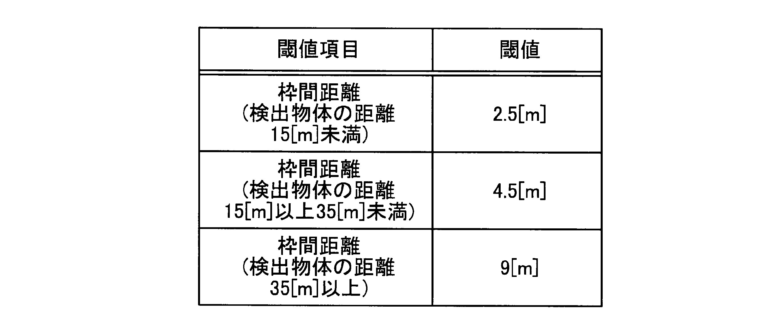

次に、図17~24を参照しながら、物体認識装置1の具体的な動作について説明する。 [Operation of Object Recognition Device]
Next, specific operations of the
図17は、実施の形態に係る視差値導出部のブロックマッチング処理の動作の一例を示すフローチャートである。図17を参照しながら、物体認識装置1の視差値導出部3のブロックマッチング処理の動作の流れについて説明する。 (Block matching process of disparity value deriving unit)
FIG. 17 is a flowchart illustrating an example of the block matching process performed by the disparity value deriving unit according to the embodiment. The flow of the block matching process of the disparity value deriving unit 3 of the
視差値導出部3の画像取得部100bは、左のカメラ(撮像部10b)により前方の被写体を撮像して、それぞれアナログの画像信号を生成し、その画像信号に基づく画像である輝度画像を得る。これによって、後段の画像処理の対象となる画像信号が得られることになる。そして、ステップS2-1へ移行する。 <Step S1-1>
The
視差値導出部3の画像取得部100aは、右のカメラ(撮像部10a)により前方の被写体を撮像して、それぞれアナログの画像信号を生成し、その画像信号に基づく画像である輝度画像を得る。これによって、後段の画像処理の対象となる画像信号が得られることになる。そして、ステップS2-2へ移行する。 <Step S1-2>
The
視差値導出部3の変換部200bは、撮像部10bにより撮像されて得られたアナログの画像信号に対して、ノイズを除去し、デジタル形式の画像データに変換する。このように、デジタル形式の画像データに変換することによって、その画像データに基づく画像に対して画素ごとの画像処理が可能となる。そして、ステップS3-1へ移行する。 <Step S2-1>
The conversion unit 200b of the parallax value derivation unit 3 removes noise from the analog image signal obtained by imaging by the
視差値導出部3の変換部200aは、撮像部10aにより撮像されて得られたアナログの画像信号に対して、ノイズを除去し、デジタル形式の画像データに変換する。このように、デジタル形式の画像データに変換することによって、その画像データに基づく画像に対して画素ごとの画像処理が可能となる。そして、ステップS3-2へ移行する。 <Step S2-2>
The
変換部200bは、ステップS2-1において変換したデジタル形式の画像データに基づく画像をブロックマッチング処理における比較画像Ibとして出力する。これによって、ブロックマッチング処理において視差値を求めるための比較対象となる画像を得る。そして、ステップS4へ移行する。 <Step S3-1>
The conversion unit 200b outputs an image based on the digital format image data converted in step S2-1 as a comparison image Ib in the block matching process. As a result, an image to be compared to obtain a parallax value in the block matching process is obtained. Then, the process proceeds to step S4.
変換部200aは、ステップS2-2において変換したデジタル形式の画像データに基づく画像をブロックマッチング処理における基準画像Iaとして出力する。これによって、ブロックマッチング処理において視差値を求めるための基準となる画像を得る。そして、ステップS4へ移行する。 <Step S3-2>
The
視差値導出部3の視差値演算処理部300のコスト算出部301は、基準画像Iaにおける基準画素p(x,y)の輝度値、および、基準画素p(x,y)に基づく比較画像Ibにおけるエピポーラ線EL上で、基準画素p(x,y)の位置に相当する画素からシフト量dでシフトすることにより特定される、対応画素の候補画素q(x+d,y)の各輝度値に基づいて、各候補画素q(x+d,y)のコスト値C(p,d)を算出することにより取得する。具体的には、コスト算出部301は、ブロックマッチング処理により、基準画像Iaの基準画素pを中心とする所定領域である基準領域pbと、比較画像Ibの候補画素qを中心とする候補領域qb(大きさは基準領域pbと同一)との非類似度をコスト値Cとして算出する。そして、ステップS5へ進む。 <Step S4>
The
視差値導出部3の視差値演算処理部300の決定部302は、コスト算出部301により算出されたコスト値Cの最小値に対応するシフト量dを、コスト値Cの算出の対象となった基準画像Iaの画素についての視差値dpとして決定する。そして、視差値導出部3の視差値演算処理部300の第1生成部303は、決定部302により決定された視差値dpに基づいて、基準画像Iaの各画素の輝度値を、その画素に対応する視差値dpで表した画像である視差画像を生成する。第1生成部303は、生成した視差画像を、認識処理部5に出力する。 <Step S5>
The
図18は、実施の形態に係る認識処理部の物体認識処理の動作の一例を示すフローチャートである。図19は、実施の形態に係る認識処理部のオーバーラップ処理の動作の一例を示すフローチャートである。図20は、枠間距離が近距離である場合の重なり面積を説明する図である。図21は、枠間距離が近距離である場合に検出物体を棄却する動作を説明する図である。図22は、枠間距離が遠距離である場合の重なり面積を説明する図である。図23は、枠間距離が遠距離である場合に重なり面積が生じない場合を説明する図である。図24は、枠間距離が遠距離である場合に検出物体を棄却しない場合を説明する図である。図18~24を参照しながら、物体認識装置1の認識処理部5の物体認識処理の動作の流れについて説明する。 (Object recognition processing of recognition processing unit)
FIG. 18 is a flowchart illustrating an example of the operation of the object recognition processing of the recognition processing unit according to the embodiment. FIG. 19 is a flowchart illustrating an example of the overlap processing operation of the recognition processing unit according to the embodiment. FIG. 20 is a diagram for explaining the overlapping area when the interframe distance is a short distance. FIG. 21 is a diagram for explaining an operation of discarding a detected object when the inter-frame distance is short. FIG. 22 is a diagram for explaining the overlapping area when the interframe distance is a long distance. FIG. 23 is a diagram for explaining the case where the overlapping area does not occur when the inter-frame distance is a long distance. FIG. 24 is a diagram for explaining the case where the detected object is not rejected when the inter-frame distance is a long distance. The flow of the object recognition process of the
第2生成部501は、視差値演算処理部300から視差画像Ipを入力し、かつ、視差値導出部3から基準画像Iaを入力し、VマップVM、UマップUM、UマップUM_H、およびリアルUマップRMの各種画像を生成する。そして、ステップS12へ移行する。 <Step S11>
The
クラスタリング処理部502の領域抽出部511は、第2生成部501から出力された各マップ(画像)のうちリアルUマップRMから、画素値の塊である孤立領域を抽出する。また、領域抽出部511は、VマップVM、UマップUMおよびリアルUマップRMを利用して、基準画像Iaまたは視差画像Ipにおいて、孤立領域の物体の位置、ならびに実際の幅、高さおよび奥行きの特定する。そして、領域抽出部511は、抽出した孤立領域ごとに、その孤立領域に関する情報である認識領域情報を生成し、ここでは、例えば、ラベリング処理の識別情報、ならびに、基準画像Ia、VマップVM、UマップUMおよびリアルUマップRM上における孤立領域の位置および大きさの情報を認識領域情報に含める。領域抽出部511は、生成した認識領域情報を、枠作成部512に送る。そして、ステップS13へ移行する。 <Step S12>
The area extraction unit 511 of the
クラスタリング処理部502の枠作成部512は、領域抽出部511により抽出されたリアルUマップRM上の物体の孤立領域について、視差画像Ip(または基準画像Ia)における孤立領域に対応する物体の検出領域に枠を作成する機能部である。枠作成部512は、視差画像Ipまたは基準画像Iaで作成した枠の情報を認識領域情報に含めて、第1棄却部513に送る。そして、ステップS14へ移行する。 <Step S13>
The
クラスタリング処理部502の第1棄却部513は、枠作成部512により枠で示される検出領域の大きさから、検出領域の検出物体についての実際のサイズ(幅、高さ、奥行き)から物体が何であるかを特定し、物体の種類に応じて棄却する。第1棄却部513は、検出物体を棄却する場合は、例えば、その検出物体の認識領域情報に棄却する旨のフラグ(棄却フラグ)を含める。第1棄却部513は、検出物体を棄却するか否かを示す棄却フラグを認識領域情報に含めて、オーバーラップ処理部514に送る。そして、ステップS15へ移行する。 <Step S14>
The
オーバーラップ処理部514は、検出領域が重なっている場合に、これらの検出領域が重なっている面積に基づいて、これらの検出領域の物体を棄却するか否かを決定するオーバーラップ処理を行う。オーバーラップ処理部514によるオーバーラップ処理について、図19を参照しながら説明する。 <Step S15>
When the detection areas overlap, the
オーバーラップ処理部514の第1判定部521は、第1棄却部513から受け取った認識領域情報に対応する検出物体のうち、任意の2つの検出物体を特定する。そして、ステップS152へ移行する。 << Step S151 >>
The
第1判定部521は、特定した2つの検出物体の検出領域が重なっているか否かを判定する。2つの検出領域が重なっている場合(ステップS152:Yes)、ステップS153へ移行し、重なっていない場合(ステップS152:No)、ステップS151へ戻り、第1判定部521は、異なる2つの検出物体を特定する。 << Step S152 >>
The
オーバーラップ処理部514の距離算出部522は、第1判定部521により検出領域が重なっていると判定された場合、重なっている検出領域の物体間の奥行き方向の枠間距離を算出する。そして、ステップS154へ移行する。 << Step S153 >>
If the
オーバーラップ処理部514の第2判定部523は、距離算出部522により算出された枠間距離が所定の閾値未満か否かを判定する。枠間距離が所定の閾値未満である場合、すなわち枠間距離が近距離である場合(ステップS154:Yes)、ステップS155へ移行し、所定の閾値よりも大きい場合、すなわち枠間距離が遠距離である場合(ステップS154:No)、ステップS159へ移行する。 << Step S154 >>
The
オーバーラップ処理部514の重なり面積算出部524は、第2判定部523により枠間距離が近距離であると判定された場合、2つの検出領域が重なっている部分の重なり面積を算出する。例えば、図20に示すように、検出領域661および検出領域662が重なり合っている場合、重なり面積算出部524は、重なり合っている領域である重なり領域663の面積を、(高さOL_H)×(幅OL_W)により算出する。そして、ステップS156へ移行する。 << Step S 155 >>
When the
オーバーラップ処理部514の第3判定部525は、重なり面積算出部524により算出された重なり面積が、2つの検出領域のうちいずれか一方の面積の所定の割合(検出領域の重なり率についての閾値)よりも大きいか否かを判定する。重なり面積が2つの検出領域のうちいずれか一方の面積の所定の割合よりも大きい場合(ステップS156:Yes)、ステップS157へ移行し、所定の割合もよりも小さい場合(ステップS156:No)、ステップS158へ移行する。 << Step S156 >>
The
オーバーラップ処理部514の第2棄却部526は、2つの検出物体が共に車両である場合、トラッキング処理の対象として重要度の高い距離が近い方の検出物体を棄却せず、距離が遠い方の検出物体を棄却する。第2棄却部526は、距離が近い方の検出物体の認識領域情報に、棄却しない旨を示す棄却フラグを含め、距離が遠い方の検出物体の認識領域情報に、棄却する旨を示す棄却フラグを含めて、トラッキング部503に送る。 << Step S 157 >>
When the two detected objects are both vehicles, the second discarding
第2棄却部526は、第3判定部525により重なり面積が、2つの検出領域のうちいずれか一方の面積の所定の割合よりも小さいと判定された場合、いずれの検出領域の物体もトラッキング処理の対象として重要度が高いと判断し、いずれの検出物体も棄却しない。第2棄却部526は、2つの検出物体のそれぞれの認識領域情報に、棄却しない旨を示す棄却フラグを含め、トラッキング部503に送る。 << Step S158 >>
When it is determined by the
重なり面積算出部524は、第2判定部523により枠間距離が遠距離であると判定された場合、2つの検出領域のうち、検出物体が近い方の検出領域の中央領域(部分領域の一例)を算出する。具体的には、図22に示すように、重なり面積算出部524は、2つの検出領域681、682のうち検出物体が近い検出領域681について、例えば、左右方向における中央の領域(例えば、左右方向の幅の80[%]の領域)の面積である中央領域681aを算出する。なお、重なり面積算出部524は、検出物体が近い方の検出領域の中央領域を算出するものとしたが、これに限定されるものではなく、例えば、検出領域の右端から所定割合(例えば、85[%])の領域を算出するものとしてもよい。そして、ステップS160へ移行する。 << Step S159 >>
When the
重なり面積算出部524は、2つの検出領域のうち、検出物体が近い方の検出領域の中央領域と、検出物体が遠い方の検出領域とが重なっている部分の重なり面積を算出する。例えば、図22に示すように、検出領域681の中央領域681aと、検出領域682とが重なり合っている場合、重なり面積算出部524は、重なり合っている領域である重なり領域683の面積を、(高さOL_H1)×(幅OL_W1)により算出する。そして、ステップS161へ移行する。 << Step S160 >>
The overlapping
第3判定部525は、重なり面積算出部524により算出された重なり面積が、検出物体が近い方の検出領域の中央領域、および検出物体が遠い方の検出領域のうちいずれか一方の面積の所定の割合(重なり率についての閾値)よりも大きいか否かを判定する。重なり面積がいずれか一方の面積の所定の割合よりも大きい場合(ステップS161:Yes)、ステップS162へ移行し、所定の割合もよりも小さい場合(ステップS161:No)、ステップS163へ移行する。 << Step S161 >>
The
第2棄却部526は、2つの検出物体のうち、トラッキング処理の対象として重要度の高い距離が近い方の検出物体を棄却せず、距離が遠い方の検出物体を棄却する。図22に示す例で、第2棄却部526は、重なり領域683の面積(重なり面積)が、中央領域681aまたは検出領域682の面積の所定の割合よりも大きい場合、距離が近い方の検出領域681の検出物体を棄却せず、距離が遠い方の検出領域682の検出物体を棄却する。第2棄却部526は、距離が近い方の検出物体の認識領域情報に、棄却しない旨を示す棄却フラグを含め、距離が遠い方の検出物体の認識領域情報に、棄却する旨を示す棄却フラグを含めて、トラッキング部503に送る。 << Step S162 >>
The second discarding
第2棄却部526は、第3判定部525により重なり面積が、検出物体が近い方の検出領域の中央領域、および検出物体が遠い方の検出領域のうちいずれか一方の面積の所定の割合よりも小さいと判定された場合、いずれの検出領域の物体もトラッキング処理の対象として重要度が高いと判断し、いずれの検出物体も棄却しない。すなわち、単純に、2つの検出領域の重なり面積が、2つの検出領域の面積のうちいずれか一方の面積の所定の割合よりも大きいと判定された場合、距離が遠い方の検出物体は棄却される可能性があるが、距離が近い方の検出領域の中央領域についての重なり面積を求めているので、検出領域同士としては端の方で重なっている距離が遠い方の棄却すべきではない検出物体(例えば、歩行者)が棄却されることを抑制することができる。第2棄却部526は、2つの検出物体のそれぞれの認識領域情報に、棄却しない旨を示す棄却フラグを含め、トラッキング部503に送る。 << Step S163 >>
The second discarding
トラッキング部503は、クラスタリング処理部502により検出された物体に関する情報である認識領域情報に基づいて、棄却フラグがOFFとなっている検出物体に対する追跡処理をするトラッキング処理を実行する。トラッキング部503は、トラッキング処理の結果を含む認識領域情報を、認識情報として車両制御装置6(図3参照)に出力する。 <Step S16>
The
In addition, when the inter-frame distance is a short distance, the area of the overlapping part of the two detection areas is calculated, and it is determined whether the area ratio of one of the two detection areas is larger than a predetermined ratio In the case where one of the two detected objects is a vehicle and the other is not a vehicle and an object smaller in size than the vehicle, the detected object which is a vehicle is not rejected but not the vehicle. And, it is assumed that the detection object smaller in size than the vehicle is rejected. In this way, objects that are not vehicles can be accurately rejected as objects that have a high possibility of false detection.
2 本体部
3 視差値導出部
4 通信線
5 認識処理部
6 車両制御装置
7 ステアリングホイール
8 ブレーキペダル
10a、10b 撮像部
11a、11b 撮像レンズ
12a、12b 絞り
13a、13b 画像センサ
20a、20b 信号変換部
21a、21b CDS
22a、22b AGC
23a、23b ADC
24a、24b フレームメモリ
30 画像処理部
31 FPGA
32 CPU
33 ROM
34 RAM
35 I/F
39 バスライン
51 FPGA
52 CPU
53 ROM
54 RAM
55 I/F
58 CANI/F
59 バスライン
60 機器制御システム
70 車両
100a、100b 画像取得部
200a、200b 変換部
300 視差値演算処理部
301 コスト算出部
302 決定部
303 第1生成部
501 第2生成部
502 クラスタリング処理部
503 トラッキング部
511 領域抽出部
512 枠作成部
513 第1棄却部
514 オーバーラップ処理部
521 第1判定部
522 距離算出部
523 第2判定部
524 重なり面積算出部
525 第3判定部
526 第2棄却部
600 路面
600a 路面部
601 電柱
601a 電柱部
602 車
602a 車部
611 左ガードレール
611a~611c 左ガードレール部
612 右ガードレール
612a~612c 右ガードレール部
613 車
613a~613c 車部
614 車
614a~614c 車部
621~624 孤立領域
631~634 検出領域
631a~634a 検出枠
641、642、651、652 検出領域
661、662 検出領域
663 重なり領域
671、672 検出枠
681 検出領域
681a 中央領域
682、682a 検出領域
683 重なり領域
691、692 検出枠
B 基線長
C コスト値
d シフト量
dp 視差値
E 物体
EL エピポーラ線
f 焦点距離
Ia 基準画像
Ib 比較画像
Ip、Ip1、Ip2 視差画像
OL_H、OL_H1 高さ
OL_W、OL_W1 幅
p 基準画素
pb 基準領域
q 候補画素
qb 候補領域
RM リアルUマップ
S、Sa、Sb 点
UM Uマップ
UM_H Uマップ
VM Vマップ
Z 距離 DESCRIPTION OF
22a, 22b AGC
23a, 23b ADC
24a, 24b Frame Memory 30 Image Processing Unit 31 FPGA
32 CPU
33 ROM
34 RAM
35 I / F
39 bus lines 51 FPGA
52 CPU
53 ROM
54 RAM
55 I / F
58 CAN I / F
59 bus line 60 device control system 70 vehicle 100a, 100b image acquisition unit 200a, 200b conversion unit 300 disparity value calculation processing unit 301 cost calculation unit 302 determination unit 303 first generation unit 501 second generation unit 502 clustering processing unit 503 tracking unit 511 area extraction unit 512 frame creation unit 513 first rejection unit 514 overlap processing unit 521 first determination unit 522 distance calculation unit 523 second determination unit 524 overlapping area calculation unit 525 third determination unit 526 second rejection unit 600 road surface 600 a Road surface portion 601 Power pole 601a Power pole portion 602 Car 602a Car portion 611 Left guard rail 611a to 611c Left guard rail portion 612 Right guard rail 612a to 612c Right guard rail portion 613 Car 613a to 613c Car portion 614 Car 614a 614 Car part 621 to 624 Isolated area 631 to 634 Detection area 631a to 634a Detection frame 641, 642, 651 and 652 Detection area 661 and 662 Detection area 663 Overlap area 671 and 672 Detection frame 681 Detection area 681a Central area 682 and 682a Detection area 683 Overlap area 691, 692 Detection frame B Baseline length C Cost value d Shift amount dp Parallax value E Object EL epipolar line f Focal length Ia Reference image Ib Comparison image Ip, Ip1, Ip2 Parallax image OL_H, OL_H1 Height OL_W, OL_W1 Width p Reference pixel pb Reference area q Candidate pixel qb Candidate area RM Real U map S, Sa, Sb point UM U map UM_H U map VM V map Z distance
Claims (12)
- 物体の距離情報に基づいて検出された2つの物体の検出領域における該物体間の奥行き方向の距離を算出する第1算出手段と、
前記第1算出手段により算出された前記距離に応じた方法により、2つの前記検出領域に関する重なりの部分の面積である重なり面積を算出する第2算出手段と、
前記重なり面積の大きさに基づいて、2つの前記検出領域の物体それぞれについて棄却の要否を決定する棄却手段と、
を備えた画像処理装置。 First calculation means for calculating the distance in the depth direction between the objects in the detection area of the two objects detected based on the distance information of the objects;
Second calculating means for calculating an overlapping area which is an area of an overlapping portion related to the two detection areas by a method according to the distance calculated by the first calculating means;
Rejecting means for determining whether or not to reject each of the objects in the two detection areas based on the size of the overlapping area;
Image processing device equipped with - 前記第1算出手段により算出された前記距離が、第1距離域に含まれるか、前記第1距離域よりも遠い第2距離域に含まれるかを判定する判定手段を、さらに備え、
前記第2算出手段は、前記判定手段により前記距離が前記第2距離域に含まれる場合、2つの前記検出領域のうち、近い物体の前記検出領域の部分領域と、遠い物体の前記検出領域とが重なった部分の面積を前記重なり面積として算出し、
前記棄却手段は、前記重なり面積が、前記部分領域、および前記遠い物体の前記検出領域のうちいずれか一方の面積の所定の割合よりも小さい場合、前記近い物体および前記遠い物体のいずれも棄却をしない請求項1に記載の画像処理装置。 It further comprises a determination means for determining whether the distance calculated by the first calculation means is included in a first distance range or in a second distance range farther than the first distance range,
When the distance is included in the second distance area by the determination means, the second calculation means may, of the two detection areas, a partial area of the detection area of the near object and the detection area of the far object. Calculating the area of the overlapping portion as the overlapping area,
When the overlapping area is smaller than a predetermined ratio of the area of either the partial area or the detection area of the distant object, the rejection means rejects both the near object and the distant object. The image processing apparatus according to claim 1. - 前記第2算出手段は、前記判定手段により前記距離が前記第2距離域に含まれる場合、前記部分領域として、前記近い物体の前記検出領域の左右方向における所定の中央領域を求め、前記中央領域と、前記遠い物体の前記検出領域とが重なった部分の面積を前記重なり面積として算出する請求項2に記載の画像処理装置。 When the distance is included in the second distance area, the second calculation means determines a predetermined central area in the lateral direction of the detection area of the near object as the partial area when the distance is included in the second distance area, and the central area The image processing apparatus according to claim 2, wherein an area of a portion where the detection area of the distant object overlaps the area of the distant object is calculated as the overlapping area.
- 前記棄却手段は、前記重なり面積が、前記部分領域、および前記遠い物体の前記検出領域のうちいずれか一方の面積の前記所定の割合よりも大きい場合、前記近い物体を棄却せず、かつ、前記遠い物体を棄却する請求項2または3に記載の画像処理装置。 The rejection means does not reject the near object when the overlapping area is larger than the predetermined ratio of the area of one of the partial region and the detection region of the far object, and The image processing apparatus according to claim 2 or 3, which rejects a distant object.
- 前記第2算出手段は、前記判定手段により前記距離が前記第1距離域に含まれる場合、2つの前記検出領域が重なった部分の面積を前記重なり面積として算出し、
前記棄却手段は、前記重なり面積が2つの前記検出領域のうちいずれか一方の面積の所定の割合よりも大きい場合、かつ、2つの前記検出領域のうち一方が車両を示し、他方が車両以外の物体を示す場合、車両である物体を棄却せず、かつ、車両以外の物体を棄却する請求項2~4のいずれか一項に記載の画像処理装置。 When the distance is included in the first distance area, the second calculating unit calculates the area of the overlapping portion of the two detection areas as the overlapping area by the determining unit.
When the overlapping area is larger than a predetermined ratio of the area of any one of the two detection areas, the rejection means indicates that one of the two detection areas indicates a vehicle and the other indicates a vehicle other than the vehicle. The image processing apparatus according to any one of claims 2 to 4, wherein when the object is indicated, the object which is a vehicle is not rejected and an object other than the vehicle is rejected. - 前記棄却手段は、前記重なり面積が2つの前記検出領域のうちいずれか一方の面積の所定の割合よりも大きい場合、かつ、2つの前記検出領域の双方が車両を示す場合、2つの前記検出領域が示す物体のうち、近い物体を棄却せず、かつ、遠い物体を棄却する請求項5に記載の画像処理装置。 When the overlapping area is larger than a predetermined ratio of the area of any one of the two detection areas, and when both of the two detection areas indicate a vehicle, the rejection means determines the two detection areas. The image processing apparatus according to claim 5, wherein among the objects indicated by, the near object is not discarded and the far object is discarded.
- 前記棄却手段は、前記重なり面積が2つの前記検出領域のうちいずれか一方の面積の所定の割合よりも小さい場合、2つの前記検出領域が示す物体のうち、近い物体および遠い物体のいずれも棄却をしない請求項5または6に記載の画像処理装置。 When the overlapping area is smaller than a predetermined ratio of the area of one of the two detection areas, the rejection means rejects both a near object and a distant object among the objects indicated by the two detection areas. The image processing apparatus according to claim 5 or 6, which does not.
- 前記距離情報に基づいて、物体を示す孤立領域を抽出する抽出手段と、
前記孤立領域に対して枠を作成することにより前記検出領域を決定する決定手段と、
をさらに備えた請求項1~7のいずれか一項に記載の画像処理装置。 Extracting means for extracting an isolated area indicating an object based on the distance information;
Determining means for determining the detection area by creating a frame for the isolated area;
The image processing apparatus according to any one of claims 1 to 7, further comprising: - 被写体を撮像することにより第1撮像画像を得る第1撮像手段と、
前記第1撮像手段の位置とは異なる位置に配置され、前記被写体を撮像することにより第2撮像画像を得る第2撮像手段と、
前記第1撮像画像および前記第2撮像画像から前記被写体に対して求めた視差値に基づいて、前記距離情報を生成する生成手段と、
請求項1~8のいずれか一項に記載の画像処理装置と、
を備えた物体認識装置。 A first imaging unit that obtains a first captured image by capturing an object;
A second imaging unit disposed at a position different from the position of the first imaging unit and acquiring a second captured image by imaging the subject;
Generation means for generating the distance information based on the parallax value determined for the subject from the first captured image and the second captured image;
An image processing apparatus according to any one of claims 1 to 8.
Object recognition device equipped with - 請求項9に記載の物体認識装置と、
前記物体認識装置により検出された物体の情報に基づいて、制御対象を制御する制御装置と、
を備えた機器制御システム。 An object recognition apparatus according to claim 9;
A control device that controls a control target based on information of the object detected by the object recognition device;
Equipment control system with. - 物体の距離情報に基づいて検出された2つの物体の検出領域における該物体間の奥行き方向の距離を算出する第1算出ステップと、
算出した前記距離に応じた方法により、2つの前記検出領域に関する重なりの部分の面積である重なり面積を算出する第2算出ステップと、
前記重なり面積の大きさに基づいて、2つの前記検出領域の物体それぞれについて棄却の要否を決定する棄却ステップと、
を有する画像処理方法。 A first calculation step of calculating a distance in a depth direction between the objects in detection areas of two objects detected based on distance information of the objects;
A second calculation step of calculating an overlapping area which is an area of overlapping portions of the two detection areas by a method according to the calculated distance;
A rejection step of determining necessity of rejection for each of the objects of the two detection areas based on the size of the overlapping area;
An image processing method having: - コンピュータを、
物体の距離情報に基づいて検出された2つの物体の検出領域における該物体間の奥行き方向の距離を算出する第1算出手段と、
前記第1算出手段により算出された前記距離に応じた方法により、2つの前記検出領域に関する重なりの部分の面積である重なり面積を算出する第2算出手段と、
前記重なり面積の大きさに基づいて、2つの前記検出領域の物体それぞれについて棄却の要否を決定する棄却手段と、
して機能させるためのプログラム。
Computer,
First calculation means for calculating the distance in the depth direction between the objects in the detection area of the two objects detected based on the distance information of the objects;
Second calculating means for calculating an overlapping area which is an area of an overlapping portion related to the two detection areas by a method according to the distance calculated by the first calculating means;
Rejecting means for determining whether or not to reject each of the objects in the two detection areas based on the size of the overlapping area;
Program to make it work.
Priority Applications (3)
| Application Number | Priority Date | Filing Date | Title |
|---|---|---|---|
| JP2018505252A JP6795027B2 (en) | 2016-03-15 | 2016-12-08 | Information processing equipment, object recognition equipment, device control systems, moving objects, image processing methods and programs |
| EP16894575.6A EP3432291A4 (en) | 2016-03-15 | 2016-12-08 | Image processing apparatus, object recognition apparatus, device control system, image processing method, and program |
| US16/130,062 US10937181B2 (en) | 2016-03-15 | 2018-09-13 | Information processing apparatus, object recognition apparatus, device control system, movable body, image processing method, and computer-readable recording medium |
Applications Claiming Priority (2)
| Application Number | Priority Date | Filing Date | Title |
|---|---|---|---|
| JP2016051447 | 2016-03-15 | ||
| JP2016-051447 | 2016-03-15 |
Related Child Applications (1)
| Application Number | Title | Priority Date | Filing Date |
|---|---|---|---|
| US16/130,062 Continuation US10937181B2 (en) | 2016-03-15 | 2018-09-13 | Information processing apparatus, object recognition apparatus, device control system, movable body, image processing method, and computer-readable recording medium |
Publications (1)
| Publication Number | Publication Date |
|---|---|
| WO2017158958A1 true WO2017158958A1 (en) | 2017-09-21 |
Family
ID=59852209
Family Applications (1)
| Application Number | Title | Priority Date | Filing Date |
|---|---|---|---|
| PCT/JP2016/086640 WO2017158958A1 (en) | 2016-03-15 | 2016-12-08 | Image processing apparatus, object recognition apparatus, device control system, image processing method, and program |
Country Status (4)
| Country | Link |
|---|---|
| US (1) | US10937181B2 (en) |
| EP (1) | EP3432291A4 (en) |
| JP (1) | JP6795027B2 (en) |
| WO (1) | WO2017158958A1 (en) |
Cited By (5)
| Publication number | Priority date | Publication date | Assignee | Title |
|---|---|---|---|---|
| CN109740518A (en) * | 2018-12-29 | 2019-05-10 | 上海依图网络科技有限公司 | The determination method and device of object in a kind of video |
| CN109800684A (en) * | 2018-12-29 | 2019-05-24 | 上海依图网络科技有限公司 | The determination method and device of object in a kind of video |
| JP2020013562A (en) * | 2018-07-16 | 2020-01-23 | 株式会社リコー | Visual odometry method, apparatus and computer-readable recording medium |
| CN111857501A (en) * | 2020-07-03 | 2020-10-30 | Oppo广东移动通信有限公司 | Information display method and device and storage medium |
| JPWO2021100115A1 (en) * | 2019-11-19 | 2021-05-27 |
Families Citing this family (11)
| Publication number | Priority date | Publication date | Assignee | Title |
|---|---|---|---|---|
| JP6516012B2 (en) * | 2015-09-15 | 2019-05-22 | 株式会社リコー | Image processing apparatus, object recognition apparatus, device control system, image processing method and program |
| EP3399499A4 (en) * | 2015-12-28 | 2019-01-09 | Ricoh Company, Ltd. | Image processing device, object recognition device, machinery control system, image processing method, and image processing program |
| US9886841B1 (en) | 2016-04-27 | 2018-02-06 | State Farm Mutual Automobile Insurance Company | Systems and methods for reconstruction of a vehicular crash |
| JP6950170B2 (en) * | 2016-11-30 | 2021-10-13 | 株式会社リコー | Information processing device, imaging device, device control system, information processing method, and program |
| WO2018119744A1 (en) * | 2016-12-28 | 2018-07-05 | 深圳前海达闼云端智能科技有限公司 | False alarm obstacle detection method and device |
| US11568554B2 (en) * | 2019-10-25 | 2023-01-31 | 7-Eleven, Inc. | Contour-based detection of closely spaced objects |
| JP7209198B2 (en) * | 2019-03-27 | 2023-01-20 | パナソニックIpマネジメント株式会社 | Distance measuring device and image generation method |
| JP2020190438A (en) | 2019-05-20 | 2020-11-26 | 株式会社リコー | Measuring device and measuring system |
| US11430134B2 (en) * | 2019-09-03 | 2022-08-30 | Nvidia Corporation | Hardware-based optical flow acceleration |
| JP7408337B2 (en) * | 2019-10-10 | 2024-01-05 | キヤノン株式会社 | Image processing method and image processing device |
| US11343485B1 (en) * | 2020-08-24 | 2022-05-24 | Ambarella International Lp | Virtual horizontal stereo camera |
Citations (4)
| Publication number | Priority date | Publication date | Assignee | Title |
|---|---|---|---|---|
| JPH07129898A (en) * | 1993-11-05 | 1995-05-19 | Toyota Central Res & Dev Lab Inc | Obstacle detecting device |
| JP2003150938A (en) * | 2001-11-09 | 2003-05-23 | Honda Motor Co Ltd | Image recognizing device |
| JP2014032542A (en) * | 2012-08-03 | 2014-02-20 | Denso Corp | Image processor and, vehicle control system using image processor |
| JP2014146267A (en) | 2013-01-30 | 2014-08-14 | Toyota Motor Corp | Pedestrian detection device and driving support device |
Family Cites Families (31)
| Publication number | Priority date | Publication date | Assignee | Title |
|---|---|---|---|---|
| US7227526B2 (en) * | 2000-07-24 | 2007-06-05 | Gesturetek, Inc. | Video-based image control system |
| US8744122B2 (en) * | 2008-10-22 | 2014-06-03 | Sri International | System and method for object detection from a moving platform |
| JP5316805B2 (en) | 2009-03-16 | 2013-10-16 | 株式会社リコー | In-vehicle camera device image adjustment device and in-vehicle camera device |
| JP5376313B2 (en) | 2009-09-03 | 2013-12-25 | 株式会社リコー | Image processing apparatus and image pickup apparatus |
| JP5664152B2 (en) | 2009-12-25 | 2015-02-04 | 株式会社リコー | Imaging device, in-vehicle imaging system, and object identification device |
| US8861842B2 (en) * | 2010-02-05 | 2014-10-14 | Sri International | Method and apparatus for real-time pedestrian detection for urban driving |
| JP5371845B2 (en) * | 2010-03-18 | 2013-12-18 | 富士フイルム株式会社 | Imaging apparatus, display control method thereof, and three-dimensional information acquisition apparatus |
| US8824779B1 (en) * | 2011-12-20 | 2014-09-02 | Christopher Charles Smyth | Apparatus and method for determining eye gaze from stereo-optic views |
| RU2582853C2 (en) * | 2012-06-29 | 2016-04-27 | Общество с ограниченной ответственностью "Системы Компьютерного зрения" | Device for determining distance and speed of objects based on stereo approach |
| US20140139635A1 (en) * | 2012-09-17 | 2014-05-22 | Nec Laboratories America, Inc. | Real-time monocular structure from motion |
| JP2014115978A (en) | 2012-11-19 | 2014-06-26 | Ricoh Co Ltd | Mobile object recognition device, notification apparatus using the device, mobile object recognition program for use in the mobile object recognition device, and mobile object with the mobile object recognition device |
| JP6467798B2 (en) | 2013-07-25 | 2019-02-13 | 株式会社リコー | Image processing apparatus, three-dimensional object detection method, three-dimensional object detection program, and moving object control system |
| JP6398347B2 (en) | 2013-08-15 | 2018-10-03 | 株式会社リコー | Image processing apparatus, recognition object detection method, recognition object detection program, and moving object control system |
| JP6174975B2 (en) * | 2013-11-14 | 2017-08-02 | クラリオン株式会社 | Ambient environment recognition device |
| JP6417886B2 (en) | 2013-12-12 | 2018-11-07 | 株式会社リコー | Parallax value deriving device, moving body, robot, parallax value production method, and program |
| JP6340850B2 (en) | 2014-03-18 | 2018-06-13 | 株式会社リコー | Three-dimensional object detection device, three-dimensional object detection method, three-dimensional object detection program, and mobile device control system |
| JP6519262B2 (en) * | 2014-04-10 | 2019-05-29 | 株式会社リコー | Three-dimensional object detection device, three-dimensional object detection method, three-dimensional object detection program, and mobile device control system |
| JP2016001170A (en) | 2014-05-19 | 2016-01-07 | 株式会社リコー | Processing unit, processing program and processing method |
| JP2016001464A (en) | 2014-05-19 | 2016-01-07 | 株式会社リコー | Processor, processing system, processing program, and processing method |
| JP6190758B2 (en) * | 2014-05-21 | 2017-08-30 | 本田技研工業株式会社 | Object recognition device and vehicle |
| JP6417729B2 (en) * | 2014-06-09 | 2018-11-07 | 株式会社リコー | Image processing apparatus, image processing method, program, parallax data production method, device control system |
| JP6550881B2 (en) * | 2014-07-14 | 2019-07-31 | 株式会社リコー | Three-dimensional object detection device, three-dimensional object detection method, three-dimensional object detection program, and mobile device control system |
| US20160019429A1 (en) | 2014-07-17 | 2016-01-21 | Tomoko Ishigaki | Image processing apparatus, solid object detection method, solid object detection program, and moving object control system |
| US9726604B2 (en) * | 2014-11-12 | 2017-08-08 | Ricoh Company, Ltd. | Adhering detection apparatus, adhering substance detection method, storage medium, and device control system for controlling vehicle-mounted devices |
| US9794543B2 (en) * | 2015-03-02 | 2017-10-17 | Ricoh Company, Ltd. | Information processing apparatus, image capturing apparatus, control system applicable to moveable apparatus, information processing method, and storage medium of program of method |
| US10043282B2 (en) * | 2015-04-13 | 2018-08-07 | Gerard Dirk Smits | Machine vision for ego-motion, segmenting, and classifying objects |
| JP2016206774A (en) * | 2015-04-17 | 2016-12-08 | トヨタ自動車株式会社 | Three-dimensional object detection apparatus and three-dimensional object detection method |
| JP6516012B2 (en) * | 2015-09-15 | 2019-05-22 | 株式会社リコー | Image processing apparatus, object recognition apparatus, device control system, image processing method and program |
| EP3399499A4 (en) | 2015-12-28 | 2019-01-09 | Ricoh Company, Ltd. | Image processing device, object recognition device, machinery control system, image processing method, and image processing program |
| WO2017145600A1 (en) * | 2016-02-23 | 2017-08-31 | 株式会社リコー | Image processing device, imaging device, mobile entity apparatus control system, image processing method, and program |
| US11087553B2 (en) * | 2019-01-04 | 2021-08-10 | University Of Maryland, College Park | Interactive mixed reality platform utilizing geotagged social media |
-
2016
- 2016-12-08 JP JP2018505252A patent/JP6795027B2/en active Active
- 2016-12-08 EP EP16894575.6A patent/EP3432291A4/en active Pending
- 2016-12-08 WO PCT/JP2016/086640 patent/WO2017158958A1/en active Application Filing
-
2018
- 2018-09-13 US US16/130,062 patent/US10937181B2/en active Active
Patent Citations (4)
| Publication number | Priority date | Publication date | Assignee | Title |
|---|---|---|---|---|
| JPH07129898A (en) * | 1993-11-05 | 1995-05-19 | Toyota Central Res & Dev Lab Inc | Obstacle detecting device |
| JP2003150938A (en) * | 2001-11-09 | 2003-05-23 | Honda Motor Co Ltd | Image recognizing device |
| JP2014032542A (en) * | 2012-08-03 | 2014-02-20 | Denso Corp | Image processor and, vehicle control system using image processor |
| JP2014146267A (en) | 2013-01-30 | 2014-08-14 | Toyota Motor Corp | Pedestrian detection device and driving support device |
Non-Patent Citations (1)
| Title |
|---|
| See also references of EP3432291A4 |
Cited By (9)
| Publication number | Priority date | Publication date | Assignee | Title |
|---|---|---|---|---|
| JP2020013562A (en) * | 2018-07-16 | 2020-01-23 | 株式会社リコー | Visual odometry method, apparatus and computer-readable recording medium |
| CN109740518A (en) * | 2018-12-29 | 2019-05-10 | 上海依图网络科技有限公司 | The determination method and device of object in a kind of video |
| CN109800684A (en) * | 2018-12-29 | 2019-05-24 | 上海依图网络科技有限公司 | The determination method and device of object in a kind of video |
| CN109800684B (en) * | 2018-12-29 | 2022-06-21 | 上海依图网络科技有限公司 | Method and device for determining object in video |
| CN109740518B (en) * | 2018-12-29 | 2022-09-27 | 上海依图网络科技有限公司 | Method and device for determining object in video |
| JPWO2021100115A1 (en) * | 2019-11-19 | 2021-05-27 | ||
| WO2021100115A1 (en) * | 2019-11-19 | 2021-05-27 | 日本電気株式会社 | Object detection device, object detection method, and program |
| JP7298708B2 (en) | 2019-11-19 | 2023-06-27 | 日本電気株式会社 | OBJECT DETECTION DEVICE, OBJECT DETECTION METHOD, AND PROGRAM |
| CN111857501A (en) * | 2020-07-03 | 2020-10-30 | Oppo广东移动通信有限公司 | Information display method and device and storage medium |
Also Published As
| Publication number | Publication date |
|---|---|
| EP3432291A1 (en) | 2019-01-23 |
| JPWO2017158958A1 (en) | 2018-10-04 |
| EP3432291A4 (en) | 2019-03-27 |
| JP6795027B2 (en) | 2020-12-02 |
| US10937181B2 (en) | 2021-03-02 |
| US20190012798A1 (en) | 2019-01-10 |
Similar Documents
| Publication | Publication Date | Title |
|---|---|---|
| WO2017158958A1 (en) | Image processing apparatus, object recognition apparatus, device control system, image processing method, and program | |
| EP2889641B1 (en) | Image processing apparatus, image processing method, program and image processing system | |
| JP6614247B2 (en) | Image processing apparatus, object recognition apparatus, device control system, image processing method and program | |
| US20200074212A1 (en) | Information processing device, imaging device, equipment control system, mobile object, information processing method, and computer-readable recording medium | |
| JP6597795B2 (en) | Image processing apparatus, object recognition apparatus, device control system, image processing method and program | |
| US10832431B2 (en) | Image processing apparatus, object recognition apparatus, equipment control system, image processing method, and computer-readable recording medium | |
| JP6547841B2 (en) | Image processing apparatus, object recognition apparatus, device control system, image processing method and program | |
| US10672141B2 (en) | Device, method, system and computer-readable medium for determining collision target object rejection | |
| JP2017151535A (en) | Image processing device, object recognition device, equipment control system, image processing method, and program | |
| JP6572696B2 (en) | Image processing apparatus, object recognition apparatus, device control system, image processing method and program | |
| JP6992356B2 (en) | Information processing equipment, image pickup equipment, equipment control system, mobile body, information processing method and program | |
| JP2005156199A (en) | Vehicle detection method and vehicle detector | |
| JP2017167970A (en) | Image processing apparatus, object recognition apparatus, device control system, image processing method, and program | |
| WO2018097269A1 (en) | Information processing device, imaging device, equipment control system, mobile object, information processing method, and computer-readable recording medium | |
| EP3540643A1 (en) | Image processing apparatus and image processing method | |
| JP6828332B2 (en) | Image processing equipment, object recognition equipment, equipment control systems, image processing methods and programs | |
| JP6701738B2 (en) | Parallax value deriving device, parallax value deriving method and program |
Legal Events
| Date | Code | Title | Description |
|---|---|---|---|
| ENP | Entry into the national phase |
Ref document number: 2018505252 Country of ref document: JP Kind code of ref document: A |
|
| NENP | Non-entry into the national phase |
Ref country code: DE |
|
| WWE | Wipo information: entry into national phase |
Ref document number: 2016894575 Country of ref document: EP |
|
| ENP | Entry into the national phase |
Ref document number: 2016894575 Country of ref document: EP Effective date: 20181015 |
|
| 121 | Ep: the epo has been informed by wipo that ep was designated in this application |
Ref document number: 16894575 Country of ref document: EP Kind code of ref document: A1 |