WO2017126533A1 - Gas collection method - Google Patents
Gas collection method Download PDFInfo
- Publication number
- WO2017126533A1 WO2017126533A1 PCT/JP2017/001500 JP2017001500W WO2017126533A1 WO 2017126533 A1 WO2017126533 A1 WO 2017126533A1 JP 2017001500 W JP2017001500 W JP 2017001500W WO 2017126533 A1 WO2017126533 A1 WO 2017126533A1
- Authority
- WO
- WIPO (PCT)
- Prior art keywords
- gas
- water
- collection
- methane
- film
- Prior art date
Links
Images


Classifications
-
- C—CHEMISTRY; METALLURGY
- C02—TREATMENT OF WATER, WASTE WATER, SEWAGE, OR SLUDGE
- C02F—TREATMENT OF WATER, WASTE WATER, SEWAGE, OR SLUDGE
- C02F1/00—Treatment of water, waste water, or sewage
- C02F1/20—Treatment of water, waste water, or sewage by degassing, i.e. liberation of dissolved gases
-
- C—CHEMISTRY; METALLURGY
- C02—TREATMENT OF WATER, WASTE WATER, SEWAGE, OR SLUDGE
- C02F—TREATMENT OF WATER, WASTE WATER, SEWAGE, OR SLUDGE
- C02F1/00—Treatment of water, waste water, or sewage
- C02F1/44—Treatment of water, waste water, or sewage by dialysis, osmosis or reverse osmosis
-
- E—FIXED CONSTRUCTIONS
- E21—EARTH DRILLING; MINING
- E21B—EARTH DRILLING, e.g. DEEP DRILLING; OBTAINING OIL, GAS, WATER, SOLUBLE OR MELTABLE MATERIALS OR A SLURRY OF MINERALS FROM WELLS
- E21B41/00—Equipment or details not covered by groups E21B15/00 - E21B40/00
- E21B41/0099—Equipment or details not covered by groups E21B15/00 - E21B40/00 specially adapted for drilling for or production of natural hydrate or clathrate gas reservoirs; Drilling through or monitoring of formations containing gas hydrates or clathrates
-
- E—FIXED CONSTRUCTIONS
- E21—EARTH DRILLING; MINING
- E21B—EARTH DRILLING, e.g. DEEP DRILLING; OBTAINING OIL, GAS, WATER, SOLUBLE OR MELTABLE MATERIALS OR A SLURRY OF MINERALS FROM WELLS
- E21B43/00—Methods or apparatus for obtaining oil, gas, water, soluble or meltable materials or a slurry of minerals from wells
- E21B43/01—Methods or apparatus for obtaining oil, gas, water, soluble or meltable materials or a slurry of minerals from wells specially adapted for obtaining from underwater installations
- E21B43/0122—Collecting oil or the like from a submerged leakage
-
- C—CHEMISTRY; METALLURGY
- C02—TREATMENT OF WATER, WASTE WATER, SEWAGE, OR SLUDGE
- C02F—TREATMENT OF WATER, WASTE WATER, SEWAGE, OR SLUDGE
- C02F2101/00—Nature of the contaminant
- C02F2101/30—Organic compounds
- C02F2101/32—Hydrocarbons, e.g. oil
-
- C—CHEMISTRY; METALLURGY
- C02—TREATMENT OF WATER, WASTE WATER, SEWAGE, OR SLUDGE
- C02F—TREATMENT OF WATER, WASTE WATER, SEWAGE, OR SLUDGE
- C02F2103/00—Nature of the water, waste water, sewage or sludge to be treated
- C02F2103/007—Contaminated open waterways, rivers, lakes or ponds
-
- C—CHEMISTRY; METALLURGY
- C02—TREATMENT OF WATER, WASTE WATER, SEWAGE, OR SLUDGE
- C02F—TREATMENT OF WATER, WASTE WATER, SEWAGE, OR SLUDGE
- C02F2103/00—Nature of the water, waste water, sewage or sludge to be treated
- C02F2103/08—Seawater, e.g. for desalination
-
- C—CHEMISTRY; METALLURGY
- C02—TREATMENT OF WATER, WASTE WATER, SEWAGE, OR SLUDGE
- C02F—TREATMENT OF WATER, WASTE WATER, SEWAGE, OR SLUDGE
- C02F2209/00—Controlling or monitoring parameters in water treatment
- C02F2209/02—Temperature
Definitions
- the present invention relates to a gas collecting method that collects a gas such as methane gas emitted from the sea bottom (hereinafter also including a lake bottom).
- Patent Document 1 discloses a method for recovering seabed resources.
- crude oil ejected from the seabed is collected by a dome-shaped frame, and is collected by a crude oil recovery ship on the sea surface via a pipe connected to the frame.
- Patent Document 1 since the purpose of the method disclosed in Patent Document 1 is to recover crude oil, it is necessary to sink the dome-shaped frame and fix it stably. For this reason, the anchor which divides
- An object of the present invention is to provide a gas collection method capable of efficiently collecting gas released from the seabed (lake bottom) without affecting marine resources on the seabed (lake bottom).
- a feature of the present invention is a gas collection method for collecting a gas generated from a raw material existing on the seabed or lake bottom, which comprises a film body having a fixture connected to the lower end and extending downward from the top.
- the film collecting is dropped into water, the three-dimensional position of the fixture in the water is grasped by a position maintainer provided in the fixture, and the three-dimensional position of the fixture is determined by autonomous navigation.
- the lower end of the trapping membrane is higher than the seabed or the lake bottom, and the raw material is separated from a solid state into water and gas based on the vertical water temperature distribution obtained by CTD.
- the lower end of the collection membrane is set at a position higher than the seabed (lake bottom) and shallower than the water depth at which the raw material separates into water and gas from the solid state. Can be collected. Furthermore, it is possible to prevent the fishery resources on the seabed (lake bottom) from being affected.
- FIG. 1 is an explanatory diagram illustrating a basic configuration [fundamental configuration] of a gas collection device that performs a gas collection method.
- FIG. 2 is a graph showing the relationship between seawater temperature and water depth at which methane hydrate is separated into water and methane.
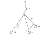
- FIG. 3 is a perspective view of the gas collecting device.
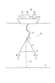
- Drawing 4 is an explanatory view showing the composition of the gas collection device which performs the gas collection method concerning an embodiment.
- FIG. 5 is a flowchart showing a collection procedure using the gas collection device.
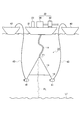
- FIG. 6 is an explanatory view showing a configuration of a modified example of the gas collection device.
- the gas collecting device 10 is subtracted from a ship 21 floating on the sea toward the sea bottom (lake bottom) L1, and spreads downward [flare (s) downward] collecting membrane [collecting membrane] ] 11. That is, the collection film 11 is formed of a film body that spreads downward from the top T1. The distance from the lower end of the collection film
- the collection film 11 is supported by four wires 12.
- a weight 13 fixed to the seabed L1 is connected to each lower end of the wire 12. That is, the weight 13 is attached to the lower end of the collection film 11 and functions as a fixture for maintaining (fixing) the collection film 11 at a desired water depth.
- the trapping film 11 supported by the wire 12 has the top T1 at the highest point.
- gas plumes gas ⁇ plume (s)] PL formed by releasing gas and gas hydrate (raw material) grains (for example, methane gas and hydrate particles) from the seabed L1.
- gas and gas hydrate raw material grains
- methane gas and hydrate particles for example, methane gas and hydrate particles
- a tube 14 (for example, a double spiral tube) is connected to the top T1 (or the vicinity thereof) of the collection film 11.
- the other end of the tube 14 is connected to an onboard unit 22 provided on the ship 21. That is, the methane gas collected by the collection film 11 is supplied to the shipboard unit 22 via the tube 14.
- the onboard unit 22 includes equipment such as a gas-liquid separator 30 connected to the tube 14 and a pressure accumulating tank 32 that accumulates recovered methane.
- the onboard unit 22 takes out the methane gas from the methane gas collected via the tube 14 and the gas-liquid mixture collected along with the methane gas, and sends the methane gas to downstream equipment.
- the extracted methane gas is sent to a gas storage tank via a pipeline.
- the trapping film 11 is made of a material that can withstand long-term use without being stretched or deteriorated even when placed in seawater for a long time.
- the lower end of the collecting film 11 is separated from the seabed L1 (see distance P1 in FIG. 1). That is, the weight 13 is sunk on the seabed L1, but the lower end of the collection film 11 is disposed at a position (shallow position) higher than the seabed L1. Moreover, the top part T1 of the collection film
- membrane 11 is arrange
- the water depth at which methane hydrate (raw material) separates into water and gas and the water depth at which the bubbles of methane gas disappear vary depending on the seawater temperature.
- the relationship between the water depth at which methane hydrate is separated into water and gas and the seawater temperature will be described with reference to FIG.
- the horizontal axis of the graph shown in FIG. 2 indicates the seawater temperature (° C.), and the vertical axis indicates the depth (m) from the sea surface.
- the + mark indicated by the reference sign Q1 indicates the seawater temperature and water depth at which methane hydrate (solid) is separated into water and gas, which is obtained by calculation. Therefore, the (approximate) curve (Q1) obtained from the + mark indicated by the reference sign Q1 is a methane hydrate stable region curve [methane hydrate stability zone curve]. On the left side of this curve Q1, methane hydrate exists as a solid. On the right side of curve Q1, methane hydrate separates into water and methane gas.
- the lower the seawater temperature the shallower the water depth that exists as methane hydrate (solid).
- methane hydrate is separated into water and gas.
- methane hydrate is separated into water and gas.
- a curve Q2 shown in FIG. 2 shows a typical water temperature change in the sea area of Japan.
- the water temperature rises rapidly when the water depth is shallower than 300 m. That is, based on the correspondence between the curve Q2 of the target sea area (here, the Japan Sea area) and the methane hydrate stable area curve Q1, the water depth at which methane gas disappears can be obtained.
- the target sea area here, the Japan Sea area
- the methane hydrate stable area curve Q1 the water depth at which methane gas disappears can be obtained.
- methane gas is generated from methane hydrate in the vicinity of a water depth of 300 m. Therefore, if the collection film 11 is installed so that the lower end of the collection film 11 is at a position shallower than the water depth of 300 m, methane gas generated from methane hydrate can be collected.
- the ship 21 is moved to the sea level above the methane plume PL.
- the weight 13 is sunk on the seabed, and the weight 13 is moved to a desired position using a robot operating in the sea. Specifically, the weight 13 is moved by remote control by the robot so that the methane plume PL is positioned at the approximate center of the spread collection film 11.
- Various robots that operate in the sea are known, and detailed description of the configuration and operation of the robot is omitted.
- a wire 12 is connected to the weight 13, and a collecting film 11 is attached to the wire 12. Accordingly, the trapping film 11 spreads downward in a quadrangular pyramid shape from the top T1 (see FIG. 3).
- the collection film 11 was expanded in a quadrangular pyramid shape using four weights 13.
- the collection film 11 may be spread in a polygonal pyramid shape using three or five or more weights 13.
- membrane 11 is a polygonal cone shape or a cone-shaped cone shape, it is not limited to these shapes.
- the collection film 11 only needs to be expanded in a shape that expands downward and has the top portion T1 as the uppermost point.
- the lower end of the collection film 11 is arranged at a position higher than the seabed L1. Therefore, as indicated by the distance P1 (see FIG. 1), a gap is formed between the seabed L1 and the lower end of the trapping film 11, so that the influence on marine resources that inhabit the seabed can be reduced.
- the top portion T1 of the collection membrane 11 is disposed at a position deeper than the water depth at which methane gas is mixed with seawater and cannot be confirmed by acoustic sonar. Methane gas separated from methane hydrate is mixed with seawater while ascending about 100 to 200 m and cannot be confirmed with acoustic sonar.
- the top T1 of the collection film 11 is disposed at a position deeper than the water depth at which methane gas is mixed with seawater and cannot be confirmed by acoustic sonar. For this reason, methane gas can be collected by the collection film
- the collected methane gas is introduced into the tube 14 connected to the top portion T ⁇ b> 1 of the collection film 11, and supplied to the onboard unit 22 provided on the ship 21.
- the supplied methane gas is separated by the gas-liquid separator 30 and stored in the pressure accumulation tank 32.
- the methane gas is collected by the collection film 11 spreading downward, so that the methane gas generated from the methane plume PL can be collected efficiently.
- the lower end of the collection film 11 is disposed at a position higher (shallow) than the seabed L1, it is possible to prevent the marine resources of the seabed L1 from being affected. Furthermore, since the lower end of the collection film 11 is disposed at a position shallower than the water depth at which the methane hydrate is separated into water and methane gas, the methane gas can be collected efficiently.
- methane gas generated from the methane plume PL is collected. Can be moved. Moreover, since the movement is easy, it is possible to easily collect methane gas released from the surface layer type methane hydrate.
- the gas collection method gas collection device 50
- the weight 13 is sunk to the seabed L 1, and the collection film 11 is spread by the wire 12 connected to the weight 13.
- the end of the wire 12 is connected to a non-cable type (non-cable type) underwater robot 31 that functions as a weight.
- the underwater robot 31 is placed at a desired depth in the sea, and the collection film 11 is spread through the wire 12. That is, the underwater robot 31 functions as a fixture for maintaining the collection film 11 at a desired water depth. Furthermore, the underwater robot 31 also functions as a position maintainer for maintaining the position of the fixture.
- the gas collection device 50 in the present embodiment includes a collection film 11 that hangs down from the ship 21 floating on the sea toward the sea bottom L1 and spreads downward.
- the collection film 11 has a configuration including a film body that spreads downward from the top T1.
- the trapping film 11 is supported by four wires 12, and an underwater robot 31 for holding at a desired position in the sea is connected to the lower end of each wire 12.
- One end side of the tube 14 is connected to the top portion T ⁇ b> 1 of the collecting film 11, and the other end side of the tube 14 is connected to an onboard unit 22 provided on the ship 21. That is, the methane gas collected by the collection film 11 is supplied to the onboard unit 22 via the tube 14.
- the underwater robot 31 has a function of grasping its own position, and can navigate in the direction of 360 degrees autonomously. That is, if the coordinates of the target position are set, the underwater robot 31 recognizes the target position by the above function, autonomously navigates to the target position, and maintains the target position. Therefore, even if a force acts from the lateral direction of the collection film 11 due to the influence of the tidal current or the like, the underwater robot 31 autonomously navigates against the tidal current and maintains the target position. Therefore, the trapping film 11 can be maintained at a desired position without causing the weight 13 to sink to the seabed L1 as in the basic configuration described above.
- step S10 the ship 21 is moved to the sea level above the methane plume PL.
- step S50 the underwater robot 31 is moved so that the methane plume PL is positioned at the approximate center of the spread collection film 11.
- the position of the underwater robot 31 can be grasped by radio or sonar.
- the wire 12 is connected to the underwater robot 31, and the collecting film 11 is attached to the wire 12. Accordingly, the trapping film 11 spreads downward in a quadrangular pyramid shape from the top portion T1 (see FIG. 4).
- the target position of the underwater robot 31 is determined (step S40)
- the underwater robot 31 is made to recognize the coordinates of the target position.
- the acquisition of the water temperature distribution (step S30) and the determination of the target position based on the water temperature distribution (step S40) will be described later.
- the target position may be set in advance before the underwater robot 31 is dropped into the sea, or may be set wirelessly. Since the underwater robot 31 performs autonomous navigation so as to remain at the target position, the trapping film 11 can stably collect methane gas from the methane plume PL (step S60).
- the metagas of the methane plume released from the seabed L1 is collected by the collection film 11 and collected by the tube 14.
- the advantages of the basic configuration described above are also brought about in this embodiment. Further, in the present embodiment, the use of the underwater robot 31 capable of autonomous navigation instead of the weight 13 provides further advantages.
- the underwater robot 31 is connected to the end of the wire 12, and the collection film 11 is maintained at a desired target position by autonomous navigation of the underwater robot 31. Therefore, it is not necessary to sink the weight 13 to the sea bottom L1 as in the basic configuration, and the collection film 11 can be installed at a desired depth even when the water depth of the sea bottom L1 is deep. As a result, methane gas can be reliably collected without being affected by the topography of the seabed L1.
- the lower end of the collection film 11 is disposed at a position (shallow) higher than the depth at which the solid methane hydrate is separated into water and methane gas, the methane gas can be collected efficiently.
- the top portion T1 of the collection membrane 11 is disposed at a position deeper than the water depth at which methane gas is mixed with seawater and cannot be confirmed by acoustic sonar. Methane gas separated from methane hydrate is mixed with seawater while ascending about 100 to 200 m and cannot be confirmed with acoustic sonar.
- the top portion T1 of the collection film 11 is disposed at a position deeper than the water depth at which methane gas is mixed with seawater and cannot be confirmed by acoustic sonar. For this reason, methane gas can be collected by the collection film
- the collected methane gas is introduced into the tube 14 connected to the top portion T ⁇ b> 1 of the collection film 11, and supplied to the onboard unit 22 provided on the ship 21.
- the supplied methane gas is separated by the gas-liquid separator 30 and stored in the pressure accumulation tank 32.
- the underwater robot 31 is connected to each end of the wire 12.
- a weight can be connected together with the underwater robot 31 in order to obtain a desired weight.
- the gas collection device 51 is a collection that hangs down from the ship 21 floating on the sea toward the sea bottom (lake bottom) L1 and spreads downward.
- a membrane 11 is provided. That is, the collection film 11 is formed of a film body that spreads downward from the top T1.
- the collection film 11 is supported by four wires 12.
- a cabled underwater robot 41 for maintaining the collecting film 11 at a desired position in the sea is connected to each lower end of the wire 12.
- a plurality of support vessels 42 for maintaining the position of each underwater robot 41 in the sea floats on the sea surface.
- Each support ship 42 is connected to the underwater robot 41 by a support wire 43.
- FIG. 6 only two sets of the underwater robot 41 and the support ship 42 are shown, but the collection film 11 is expanded by the four sets of the underwater robot 41 and the support ship 42.
- Each support ship 42 has a function of grasping its own position, and can recognize the position (latitude / longitude) of the underwater robot 41 based on the relative positional relationship with the underwater robot 41. Therefore, the underwater robot 41 can be maintained at a desired target position by controlling the position of the support ship 42 even if the underwater robot 41 itself does not have an autonomous navigation function or a function of grasping its own position.
- the target position may be set in advance before dropping the underwater robot 41 into the sea, may be set wirelessly, or may be set by wire via the support wire 43. Also, the position of the underwater robot 31 can be grasped by wire, wireless or sonar.
- a roped underwater robot 41 is connected to the end of the wire 12, and the underwater robot 41 is connected to the support ship 42.
- the underwater robot 41 is moved by the navigation of the support ship 42 to maintain the collection film 11 at a desired target position. Therefore, it is not necessary to sink the weight 13 to the sea bottom L1 as in the basic configuration, and the collection film 11 can be installed at a desired depth even when the water depth of the sea bottom L1 is deep. As a result, methane gas can be reliably collected without being affected by the topography of the seabed L1.
- the underwater robot 41 since the underwater robot 41 is connected to the support ship 42 by the support wire 43, it is not necessary for the underwater robot 41 to have an autonomous navigation function. Therefore, the configuration of the underwater robot 41 can be simplified, and the apparatus scale can be reduced.
- the water temperature distribution in the vertical direction of the sea area is acquired in advance using a measuring device 23 such as CTD (Conductivity Temperature Depth profiler) (step S30).
- CTD Conductivity Temperature Depth profiler
- the water depth at the target position of the collection membrane 11 is determined based on the water depth at the intersection of the curve Q2 in the middle) and the methane hydrate stable region curve (see the curve Q1 in FIG. 2). Further, the horizontal coordinate of the target position of the collection film 11 is determined in consideration of the position (path) of the methane plume PL.
- the lower end of the collection film 11 is set at a position higher than the seabed and shallower than the water depth at which methane hydrate is separated into water and gas, and the top T1 of the collection film 11 is filled with seawater.
- the position of the collection film 11 that is set at a position deeper than the water depth at which the bubbles disappear is mixed as the target position (step S40).
- the gas collection method of the present invention is not limited to the above embodiment (and its modifications).
- the configuration of each part can be replaced with any configuration having the same function.
- methane gas released from methane hydrate existing under the seabed is collected.
- the present invention can also be applied to collecting gas hydrates other than methane hydrate, for example, gas released from ethane hydrate or butane hydrate.
- the acquisition of the water temperature distribution may be performed before the determination of the target position (step S40). Further, the determination of the target position (step S40) may be performed before the underwater robot 31 (41) is dropped into the sea, or may be performed after the drop. However, the determination of the target position (step S40) must be performed before maintaining (moving) the underwater robot 31 (41) at the target position (step S50).
Abstract
Description
まず、実施形態に先立って、ガス捕集方法を行うガス捕集装置の基本構成について説明する。図1に示されるように、ガス捕集装置10は、海上に浮く船21から海底(湖底)L1に向けて沈下され、下方に向けて広がる[flare(s) downward]捕集膜[collecting membrane]11を備えている。即ち、捕集膜11は、その頂部T1から下方に向けて広がる膜体で構成されている。捕集膜11の下端から頂部T1までの距離は、例えば100mである。捕集膜11は4本のワイヤー12によって支持されている。ワイヤー12の各下端には、海底L1に固定される錘13が連結されている。即ち、錘13は、捕集膜11の下端に取り付けられ、捕集膜11を所望の水深に維持する(固定する)固定具[fixture]として機能する。 [Basic configuration]
First, prior to the embodiment, a basic configuration of a gas collection device that performs a gas collection method will be described. As shown in FIG. 1, the gas collecting
次に、実施形態に係るガス捕集方法(ガス捕集装置50)について説明する。上述した基本構成では、錘13を海底L1に沈下させ、錘13に接続されたワイヤー12で捕集膜11が広げられた。本実施形態では、ワイヤー12の端部は錘として機能する無索の[non-cable type](紐付されていない[untethered])水中ロボット31に接続されている。水中ロボット31を海中の所望の水深に配置して、ワイヤー12を介して捕集膜11を広げる。即ち、水中ロボット31は、捕集膜11を所望の水深に維持する固定具として機能する。更に、水中ロボット31は、固定具の位置を維持するための位置維持器[position maintainer]としても機能する。 [Embodiment]
Next, the gas collection method (gas collection device 50) according to the embodiment will be described. In the basic configuration described above, the
次に、上記実施形態の変形例について説明する。上記実施形態では、無索の水中ロボット31の自律航行によって、捕集膜11が所望の目標位置に維持された。これに対して、本変形例では、有索の[cable type](紐付されている[tethered])水中ロボット41によって、捕集膜11が所望の目標位置に維持される。以下、図6を参照して変形例を詳細に説明する。 [Modification]
Next, a modification of the above embodiment will be described. In the above embodiment, the trapping
Claims (2)
- 海底又は湖底に存在する原料から発生するガスを捕集するガス捕集方法であって、
下端に固定具が接続された、頂部から下方に向けて広がる膜体からなる捕集膜を、水中に投下し、
前記固定具に設けられた位置維持器によって前記固定具の前記水中での三次元位置を把握して、自律航行によって前記固定具の前記三次元位置を目標位置に維持し、
CTDによって取得される鉛直方向の水温分布に基づいて、前記捕集膜の前記下端を、前記海底又は前記湖底よりも高く、かつ、前記原料が固体状態から水とガスとに分離する水深よりも浅い位置に設定すると共に、前記捕集膜の前記頂部を、前記ガスが海水又は湖水に混じって前記ガスの気泡が消失する水深よりも深い位置に設定し、
前記海底又は前記湖底より放出されるガスを前記捕集膜で捕集する、ガス捕集方法。 A gas collection method for collecting gas generated from raw materials existing on the seabed or lake bottom,
A trapping membrane consisting of a membrane body, which has a fixture connected to the lower end and spreads downward from the top, is dropped into water,
By grasping the three-dimensional position of the fixture in the water by a position maintainer provided in the fixture, maintaining the three-dimensional position of the fixture at a target position by autonomous navigation,
Based on the vertical water temperature distribution obtained by CTD, the lower end of the collection membrane is higher than the sea bottom or the lake bottom, and more than the water depth at which the raw material is separated into water and gas from a solid state. While setting to a shallow position, the top of the collection membrane is set to a position deeper than the water depth where the gas is mixed with seawater or lake water and the gas bubbles disappear,
A gas collection method for collecting gas released from the seabed or the lake bottom with the collection film. - 請求項1に記載のガス捕集方法であって、
前記原料が、メタンハイドレートであり、
前記メタンハイドレートが水とガスとに分離する水深と水温との関係を示すメタンハイドレート安定領域曲線を取得し、
前記水温分布と前記メタンハイドレート安定領域曲線との交点近傍の水深を、前記捕集膜の前記下端の位置として設定する、ガス捕集方法。 The gas collection method according to claim 1,
The raw material is methane hydrate,
Obtain a methane hydrate stable region curve indicating the relationship between the water depth and water temperature at which the methane hydrate separates into water and gas,
The gas collection method of setting the water depth near the intersection of the water temperature distribution and the methane hydrate stable region curve as the position of the lower end of the collection membrane.
Priority Applications (6)
| Application Number | Priority Date | Filing Date | Title |
|---|---|---|---|
| AU2017210423A AU2017210423B2 (en) | 2016-01-21 | 2017-01-18 | Gas Collecting Method |
| KR1020187024057A KR20180102178A (en) | 2016-01-21 | 2017-01-18 | Gas collection method |
| RU2018130067A RU2698338C1 (en) | 2016-01-21 | 2017-01-18 | Gas collection method |
| US16/071,305 US11370672B2 (en) | 2016-01-21 | 2017-01-18 | Gas collecting method |
| EP17741410.9A EP3428384B1 (en) | 2016-01-21 | 2017-01-18 | Gas collection method |
| CN201780007397.9A CN108699900A (en) | 2016-01-21 | 2017-01-18 | Gas trapping method |
Applications Claiming Priority (2)
| Application Number | Priority Date | Filing Date | Title |
|---|---|---|---|
| JP2016009815A JP2017128950A (en) | 2016-01-21 | 2016-01-21 | Gas collecting method |
| JP2016-009815 | 2016-01-21 |
Publications (1)
| Publication Number | Publication Date |
|---|---|
| WO2017126533A1 true WO2017126533A1 (en) | 2017-07-27 |
Family
ID=59362136
Family Applications (1)
| Application Number | Title | Priority Date | Filing Date |
|---|---|---|---|
| PCT/JP2017/001500 WO2017126533A1 (en) | 2016-01-21 | 2017-01-18 | Gas collection method |
Country Status (8)
| Country | Link |
|---|---|
| US (1) | US11370672B2 (en) |
| EP (1) | EP3428384B1 (en) |
| JP (1) | JP2017128950A (en) |
| KR (1) | KR20180102178A (en) |
| CN (1) | CN108699900A (en) |
| AU (1) | AU2017210423B2 (en) |
| RU (1) | RU2698338C1 (en) |
| WO (1) | WO2017126533A1 (en) |
Cited By (2)
| Publication number | Priority date | Publication date | Assignee | Title |
|---|---|---|---|---|
| CN108190759A (en) * | 2017-12-22 | 2018-06-22 | 国家海洋局第海洋研究所 | Protective device is recycled in a kind of dispensing for CTD seawater sampling equipments |
| JP7141653B1 (en) | 2022-05-21 | 2022-09-26 | ▲昇▼ 蓮池 | Gas sampling device |
Families Citing this family (5)
| Publication number | Priority date | Publication date | Assignee | Title |
|---|---|---|---|---|
| CN110631870A (en) * | 2018-06-21 | 2019-12-31 | 中国石油化工股份有限公司 | Gas taking device and gas taking method suitable for seabed free gas |
| CN112145133B (en) * | 2020-09-25 | 2021-12-14 | 中国石油大学(华东) | Deep sea seabed natural gas hydrate acquisition method and production greenhouse |
| CN112253058B (en) * | 2020-10-19 | 2021-07-27 | 青岛海洋地质研究所 | System and method for artificially enriching and exploiting deep-water shallow-layer low-abundance unconventional natural gas |
| CN112282707B (en) * | 2020-12-18 | 2021-11-19 | 福州大学 | Sea natural gas hydrate barrel type mining device and method thereof |
| CN113431539A (en) * | 2021-07-05 | 2021-09-24 | 湖北茂思晟石油新技术开发有限公司 | Throwing-fishing type cableless concentric intelligent water distributor device |
Citations (8)
| Publication number | Priority date | Publication date | Assignee | Title |
|---|---|---|---|---|
| US3926056A (en) * | 1974-09-26 | 1975-12-16 | Us Navy | Conductivity, temperature and pressure measuring system |
| US4749254A (en) * | 1985-04-03 | 1988-06-07 | Seaver George A | Optical sensor system |
| JPH1029785A (en) * | 1996-07-12 | 1998-02-03 | Ishikawajima Harima Heavy Ind Co Ltd | Hoisting device provided with slack prevention shaeve |
| JP2000282775A (en) * | 1999-03-29 | 2000-10-10 | Taiyo Kogyo Corp | Method and device for collecting methane hydrate gas |
| WO2006070577A1 (en) * | 2004-12-28 | 2006-07-06 | Independent Administrative Institution, Japan Agency For Marine-Earth Science And Technology | Sinkable float and method of using sinkable float |
| JP2012021357A (en) | 2010-07-16 | 2012-02-02 | Taiyo Kogyo Corp | Recovery method of crude oil spouting on sea bottom |
| JP3184629U (en) * | 2010-07-13 | 2013-07-11 | スピリットステッサー,ウルフ | Protective device for collecting fluid leaking into water |
| US20150354957A1 (en) * | 2014-06-09 | 2015-12-10 | Ocean University Of China | Reciprocating ocean microstructure profiler |
Family Cites Families (14)
| Publication number | Priority date | Publication date | Assignee | Title |
|---|---|---|---|---|
| RU2078199C1 (en) * | 1994-06-16 | 1997-04-27 | Флориан Александрович Шестаченко | Method of offshore gas production |
| JP4261813B2 (en) * | 2002-03-28 | 2009-04-30 | 三井造船株式会社 | Gas hydrate undersea generation method, gas hydrate generation apparatus, and carbon dioxide underwater storage system |
| RO119637B1 (en) * | 2002-06-03 | 2005-01-28 | Petru Baciu | Process and installation for extracting pit gas from sea bottom |
| JP2004271326A (en) * | 2003-03-07 | 2004-09-30 | Taisei Corp | Seabed behavior measurement system |
| US7546880B2 (en) * | 2006-12-12 | 2009-06-16 | The University Of Tulsa | Extracting gas hydrates from marine sediments |
| JP5294110B2 (en) | 2008-07-07 | 2013-09-18 | 清水建設株式会社 | Methane gas production method from methane hydrate and apparatus for producing methane gas from methane hydrate |
| JP5523737B2 (en) | 2009-05-08 | 2014-06-18 | 一般財団法人電力中央研究所 | Methane hydrate mining method using carbon dioxide |
| RU87263U1 (en) * | 2009-05-25 | 2009-09-27 | Тихоокеанский океанологический институт им. В.И. Ильичева Дальневосточного отделения Российской академии наук (ТОИ ДВО РАН) | DEVICE FOR DETERMINING THE LOCATION OF THE SOURCES OF GAS "TORCHES" ON THE BOTTOM OF THE RESERVOIRS |
| JP5208862B2 (en) | 2009-06-12 | 2013-06-12 | 一般財団法人電力中央研究所 | Emulsion production / injection apparatus and method, and methane hydrate mining method |
| JP5365865B2 (en) | 2009-09-03 | 2013-12-11 | 清水建設株式会社 | Methane gas production apparatus from methane hydrate and method for producing methane gas from methane hydrate using the same |
| JP5748985B2 (en) | 2010-11-24 | 2015-07-15 | 一般財団法人電力中央研究所 | Gas hydrate production promotion method and gas resource enhanced recovery method |
| AU2012396842B2 (en) * | 2012-12-13 | 2016-02-04 | Halliburton Energy Services, Inc. | Assembly and method for subsea hydrocarbon gas recovery |
| EP2824276A1 (en) * | 2013-07-09 | 2015-01-14 | The European Union, represented by the European Commission | A device for collecting methane gas |
| CN105019868B (en) * | 2015-07-30 | 2018-01-30 | 迈瑞尔实验设备(上海)有限公司 | A kind of recovery method of seabed combustible ice |
-
2016
- 2016-01-21 JP JP2016009815A patent/JP2017128950A/en active Pending
-
2017
- 2017-01-18 CN CN201780007397.9A patent/CN108699900A/en active Pending
- 2017-01-18 KR KR1020187024057A patent/KR20180102178A/en not_active Application Discontinuation
- 2017-01-18 US US16/071,305 patent/US11370672B2/en active Active
- 2017-01-18 EP EP17741410.9A patent/EP3428384B1/en active Active
- 2017-01-18 AU AU2017210423A patent/AU2017210423B2/en active Active
- 2017-01-18 WO PCT/JP2017/001500 patent/WO2017126533A1/en active Application Filing
- 2017-01-18 RU RU2018130067A patent/RU2698338C1/en active
Patent Citations (8)
| Publication number | Priority date | Publication date | Assignee | Title |
|---|---|---|---|---|
| US3926056A (en) * | 1974-09-26 | 1975-12-16 | Us Navy | Conductivity, temperature and pressure measuring system |
| US4749254A (en) * | 1985-04-03 | 1988-06-07 | Seaver George A | Optical sensor system |
| JPH1029785A (en) * | 1996-07-12 | 1998-02-03 | Ishikawajima Harima Heavy Ind Co Ltd | Hoisting device provided with slack prevention shaeve |
| JP2000282775A (en) * | 1999-03-29 | 2000-10-10 | Taiyo Kogyo Corp | Method and device for collecting methane hydrate gas |
| WO2006070577A1 (en) * | 2004-12-28 | 2006-07-06 | Independent Administrative Institution, Japan Agency For Marine-Earth Science And Technology | Sinkable float and method of using sinkable float |
| JP3184629U (en) * | 2010-07-13 | 2013-07-11 | スピリットステッサー,ウルフ | Protective device for collecting fluid leaking into water |
| JP2012021357A (en) | 2010-07-16 | 2012-02-02 | Taiyo Kogyo Corp | Recovery method of crude oil spouting on sea bottom |
| US20150354957A1 (en) * | 2014-06-09 | 2015-12-10 | Ocean University Of China | Reciprocating ocean microstructure profiler |
Non-Patent Citations (1)
| Title |
|---|
| See also references of EP3428384A4 |
Cited By (4)
| Publication number | Priority date | Publication date | Assignee | Title |
|---|---|---|---|---|
| CN108190759A (en) * | 2017-12-22 | 2018-06-22 | 国家海洋局第海洋研究所 | Protective device is recycled in a kind of dispensing for CTD seawater sampling equipments |
| CN108190759B (en) * | 2017-12-22 | 2019-12-13 | 自然资源部第一海洋研究所 | A put in and retrieve protector for CTD sea water sampling equipment |
| JP7141653B1 (en) | 2022-05-21 | 2022-09-26 | ▲昇▼ 蓮池 | Gas sampling device |
| JP2023171696A (en) * | 2022-05-21 | 2023-12-04 | ▲昇▼ 蓮池 | gas sampling device |
Also Published As
| Publication number | Publication date |
|---|---|
| AU2017210423B2 (en) | 2020-02-06 |
| US20210206659A1 (en) | 2021-07-08 |
| JP2017128950A (en) | 2017-07-27 |
| EP3428384A1 (en) | 2019-01-16 |
| CN108699900A (en) | 2018-10-23 |
| EP3428384A4 (en) | 2019-09-18 |
| RU2698338C1 (en) | 2019-08-26 |
| US11370672B2 (en) | 2022-06-28 |
| EP3428384B1 (en) | 2023-06-14 |
| AU2017210423A1 (en) | 2018-08-09 |
| KR20180102178A (en) | 2018-09-14 |
Similar Documents
| Publication | Publication Date | Title |
|---|---|---|
| WO2017126533A1 (en) | Gas collection method | |
| US4643612A (en) | Oil cleanup barge | |
| US7025533B1 (en) | Concentrated buoyancy subsea pipeline apparatus and method | |
| WO2011106070A3 (en) | Vertical glider robot | |
| CA2918079A1 (en) | Riser flow control | |
| US20160077212A1 (en) | Tracking buoy | |
| WO2008105302A1 (en) | Foam recovering apparatus and foam recovering system | |
| KR101487513B1 (en) | Wave absorbing apparatus of moonpool | |
| US20120000411A1 (en) | Anchor device for coral rock | |
| JP2017075469A (en) | Collection device for water bottom flowing methane gas and collection method for the same | |
| KR101472828B1 (en) | Floating module and device for TRBM | |
| KR101563671B1 (en) | Separation device for floating Offshore Structure | |
| KR101835154B1 (en) | Ice collision preventing structure of Half-Submerging Drilling Ship | |
| CN115867830A (en) | Seismic data acquisition unit device and positioning system and method | |
| KR101753968B1 (en) | Marine structure | |
| US20120037063A1 (en) | Subsea collection and containment system for hydrocarbon emissions. | |
| KR200479276Y1 (en) | Anchor for mooring of ship and marine structure | |
| KR101722079B1 (en) | Apparatus for mooring | |
| TW200622140A (en) | Deep ocean water drawing device | |
| KR101750962B1 (en) | Cylinder type structure for subsea process | |
| KR101588718B1 (en) | Marine structure | |
| KR101556187B1 (en) | Wave absorbing apparatus of moonpool | |
| KR20120018902A (en) | Drill ship having inclined moonpool | |
| KR20160057959A (en) | Offshore structure | |
| KR102372850B1 (en) | Bubble-type skim pile |
Legal Events
| Date | Code | Title | Description |
|---|---|---|---|
| 121 | Ep: the epo has been informed by wipo that ep was designated in this application |
Ref document number: 17741410 Country of ref document: EP Kind code of ref document: A1 |
|
| NENP | Non-entry into the national phase |
Ref country code: DE |
|
| ENP | Entry into the national phase |
Ref document number: 2017210423 Country of ref document: AU Date of ref document: 20170118 Kind code of ref document: A |
|
| ENP | Entry into the national phase |
Ref document number: 20187024057 Country of ref document: KR Kind code of ref document: A |
|
| WWE | Wipo information: entry into national phase |
Ref document number: 1020187024057 Country of ref document: KR Ref document number: 2017741410 Country of ref document: EP |
|
| ENP | Entry into the national phase |
Ref document number: 2017741410 Country of ref document: EP Effective date: 20180821 |