WO2017094620A1 - Voltage measurement device, voltage measurement system - Google Patents
Voltage measurement device, voltage measurement system Download PDFInfo
- Publication number
- WO2017094620A1 WO2017094620A1 PCT/JP2016/085014 JP2016085014W WO2017094620A1 WO 2017094620 A1 WO2017094620 A1 WO 2017094620A1 JP 2016085014 W JP2016085014 W JP 2016085014W WO 2017094620 A1 WO2017094620 A1 WO 2017094620A1
- Authority
- WO
- WIPO (PCT)
- Prior art keywords
- voltage
- storage device
- relay
- power storage
- voltage measurement
- Prior art date
Links
Images


Classifications
-
- G—PHYSICS
- G01—MEASURING; TESTING
- G01R—MEASURING ELECTRIC VARIABLES; MEASURING MAGNETIC VARIABLES
- G01R31/00—Arrangements for testing electric properties; Arrangements for locating electric faults; Arrangements for electrical testing characterised by what is being tested not provided for elsewhere
- G01R31/36—Arrangements for testing, measuring or monitoring the electrical condition of accumulators or electric batteries, e.g. capacity or state of charge [SoC]
- G01R31/382—Arrangements for monitoring battery or accumulator variables, e.g. SoC
- G01R31/3835—Arrangements for monitoring battery or accumulator variables, e.g. SoC involving only voltage measurements
-
- B—PERFORMING OPERATIONS; TRANSPORTING
- B60—VEHICLES IN GENERAL
- B60R—VEHICLES, VEHICLE FITTINGS, OR VEHICLE PARTS, NOT OTHERWISE PROVIDED FOR
- B60R16/00—Electric or fluid circuits specially adapted for vehicles and not otherwise provided for; Arrangement of elements of electric or fluid circuits specially adapted for vehicles and not otherwise provided for
- B60R16/02—Electric or fluid circuits specially adapted for vehicles and not otherwise provided for; Arrangement of elements of electric or fluid circuits specially adapted for vehicles and not otherwise provided for electric constitutive elements
- B60R16/03—Electric or fluid circuits specially adapted for vehicles and not otherwise provided for; Arrangement of elements of electric or fluid circuits specially adapted for vehicles and not otherwise provided for electric constitutive elements for supply of electrical power to vehicle subsystems or for
- B60R16/033—Electric or fluid circuits specially adapted for vehicles and not otherwise provided for; Arrangement of elements of electric or fluid circuits specially adapted for vehicles and not otherwise provided for electric constitutive elements for supply of electrical power to vehicle subsystems or for characterised by the use of electrical cells or batteries
-
- B—PERFORMING OPERATIONS; TRANSPORTING
- B60—VEHICLES IN GENERAL
- B60R—VEHICLES, VEHICLE FITTINGS, OR VEHICLE PARTS, NOT OTHERWISE PROVIDED FOR
- B60R16/00—Electric or fluid circuits specially adapted for vehicles and not otherwise provided for; Arrangement of elements of electric or fluid circuits specially adapted for vehicles and not otherwise provided for
- B60R16/02—Electric or fluid circuits specially adapted for vehicles and not otherwise provided for; Arrangement of elements of electric or fluid circuits specially adapted for vehicles and not otherwise provided for electric constitutive elements
- B60R16/04—Arrangement of batteries
-
- H—ELECTRICITY
- H01—ELECTRIC ELEMENTS
- H01M—PROCESSES OR MEANS, e.g. BATTERIES, FOR THE DIRECT CONVERSION OF CHEMICAL ENERGY INTO ELECTRICAL ENERGY
- H01M10/00—Secondary cells; Manufacture thereof
- H01M10/42—Methods or arrangements for servicing or maintenance of secondary cells or secondary half-cells
- H01M10/48—Accumulators combined with arrangements for measuring, testing or indicating the condition of cells, e.g. the level or density of the electrolyte
-
- H—ELECTRICITY
- H02—GENERATION; CONVERSION OR DISTRIBUTION OF ELECTRIC POWER
- H02J—CIRCUIT ARRANGEMENTS OR SYSTEMS FOR SUPPLYING OR DISTRIBUTING ELECTRIC POWER; SYSTEMS FOR STORING ELECTRIC ENERGY
- H02J7/00—Circuit arrangements for charging or depolarising batteries or for supplying loads from batteries
- H02J7/0047—Circuit arrangements for charging or depolarising batteries or for supplying loads from batteries with monitoring or indicating devices or circuits
- H02J7/0048—Detection of remaining charge capacity or state of charge [SOC]
-
- H—ELECTRICITY
- H02—GENERATION; CONVERSION OR DISTRIBUTION OF ELECTRIC POWER
- H02J—CIRCUIT ARRANGEMENTS OR SYSTEMS FOR SUPPLYING OR DISTRIBUTING ELECTRIC POWER; SYSTEMS FOR STORING ELECTRIC ENERGY
- H02J7/00—Circuit arrangements for charging or depolarising batteries or for supplying loads from batteries
- H02J7/14—Circuit arrangements for charging or depolarising batteries or for supplying loads from batteries for charging batteries from dynamo-electric generators driven at varying speed, e.g. on vehicle
-
- Y—GENERAL TAGGING OF NEW TECHNOLOGICAL DEVELOPMENTS; GENERAL TAGGING OF CROSS-SECTIONAL TECHNOLOGIES SPANNING OVER SEVERAL SECTIONS OF THE IPC; TECHNICAL SUBJECTS COVERED BY FORMER USPC CROSS-REFERENCE ART COLLECTIONS [XRACs] AND DIGESTS
- Y02—TECHNOLOGIES OR APPLICATIONS FOR MITIGATION OR ADAPTATION AGAINST CLIMATE CHANGE
- Y02E—REDUCTION OF GREENHOUSE GAS [GHG] EMISSIONS, RELATED TO ENERGY GENERATION, TRANSMISSION OR DISTRIBUTION
- Y02E60/00—Enabling technologies; Technologies with a potential or indirect contribution to GHG emissions mitigation
- Y02E60/10—Energy storage using batteries
-
- Y—GENERAL TAGGING OF NEW TECHNOLOGICAL DEVELOPMENTS; GENERAL TAGGING OF CROSS-SECTIONAL TECHNOLOGIES SPANNING OVER SEVERAL SECTIONS OF THE IPC; TECHNICAL SUBJECTS COVERED BY FORMER USPC CROSS-REFERENCE ART COLLECTIONS [XRACs] AND DIGESTS
- Y02—TECHNOLOGIES OR APPLICATIONS FOR MITIGATION OR ADAPTATION AGAINST CLIMATE CHANGE
- Y02T—CLIMATE CHANGE MITIGATION TECHNOLOGIES RELATED TO TRANSPORTATION
- Y02T10/00—Road transport of goods or passengers
- Y02T10/60—Other road transportation technologies with climate change mitigation effect
- Y02T10/70—Energy storage systems for electromobility, e.g. batteries
Definitions
- the present invention relates to a voltage measurement apparatus, and more particularly to a technology for measuring an open circuit voltage of an on-vehicle storage device.
- Patent Document 1 discloses a technique in which a main battery and a sub battery are provided side by side, and the internal resistance of the sub battery is measured from the current value and the voltage value when charging the smoothing capacitor with the sub battery.
- power supply to the on-board electrical load may require not only the alternator but also the discharge current of the storage device while the vehicle is traveling. And since this discharge path has a common part with the above-mentioned charge path, if the charge path is merely shut off, there is a possibility that the electric load is not sufficiently fed.
- this invention aims at providing the technique which avoids that the electric power in driving
- the voltage measurement device measures an open circuit voltage of a first power storage device indirectly connected to a generator mounted on the vehicle and a DC bus connected to the vehicle load.
- the voltage measurement device includes a power supply circuit connected to the DC bus, a first voltage measurement unit that measures a first voltage applied to the power supply circuit, and an intervening unit between the DC bus and the first power storage device.
- a relay having a first end connected to the DC bus and a second end connected to the first power storage device, and receiving operating power from the power supply circuit to control the opening and closing of the relay;
- a control circuit that closes between the first end and the second end when a first voltage is less than a first threshold, and a second voltage applied to the second end, at least the relay is open
- a second voltage measuring unit that measures the time.
- FIG. 1 is a block diagram illustrating the configuration of the voltage measurement device 2A and the configuration around it.
- the voltage measurement device 2A has a function of measuring the open circuit voltage of the power storage device 1 (indicated as "BAT” in the figure) mounted on the vehicle.
- Power storage device 1 is connected to alternator 4 (denoted by “ALT” in the drawing) via DC bus 211.
- the alternator 4 functions as an on-vehicle generator that generates electric power by rotation of an engine (not shown), and charges the power storage device 1 with the DC bus 211 as a charging path.
- a positive potential is applied to the DC bus 211.
- the voltage (generated voltage) generated by the alternator 4 is controlled by the engine ECU (Electronic Control Unit) 5 to be a predetermined voltage value.
- ECU Electronic Control Unit
- Power storage device 1 may be, for example, a lead storage battery or an electric double layer capacitor.
- the vehicle load 3 is an on-vehicle electrical load, and can be supplied with power from either the alternator 4 or the storage device 1 via the DC bus 211.
- the voltage measurement device 2A includes a relay 200, a power supply circuit 203, voltage measurement units 201 and 202, and a control circuit 204.
- the power supply circuit 203 is connected to the DC bus 211, converts the voltage Vb supplied from the DC bus 211, and supplies the converted voltage Vb to the control circuit 204.
- the voltage Vb is measured by a voltage measurement unit 202 (indicated as “voltage monitor B” in the drawing).
- Relay 200 is interposed between power storage device 1 and DC bus 211, and has ends 200a and 200b.
- power storage device 1 is indirectly connected to DC bus 211 via relay 200.
- End 200 a is connected to power storage device 1
- end 200 b is connected to DC bus 211.
- the voltage Vb is closed (short circuit) when the voltage Vb is lower than the first threshold and is opened (opened) when the voltage Vb is higher than the second threshold.
- the first threshold is smaller than the second threshold.
- the ends 200b and 200a can be grasped as a first end and a second end, respectively.
- the control circuit 204 (denoted as “CPU” in the figure) operates by receiving operating power from the power supply circuit 203.
- the control circuit 204 can be realized using a known microcomputer.
- a specific first operation of the control circuit 204 is to make the engine ECU 5 control the generated voltage of the alternator 4.
- a specific second operation is to make the voltage measurement unit 202 measure the voltage Vb applied to the power supply circuit 203, and control the opening / closing of the relay 200 based on the value.
- a specific third operation is to cause the voltage measurement unit 201 (indicated as “voltage monitor A” in the drawing) to measure the voltage Va applied to the end 200 a at least when the relay 200 is in the open state. .
- the voltage measuring units 202 and 201 can be grasped as a first voltage measuring unit and a second voltage measuring unit, respectively.
- FIG. 2 is a flowchart illustrating the operation of the voltage measurement device 2A according to the first embodiment, and shows control by the control circuit 204. Steps S101 to S104, S106, and S108 correspond to the above-described second operation, and steps S105 and S107 correspond to the above-described third operation. “Battery diagnosis” in FIG. 2 refers to a diagnosis of the power storage device 1. The diagnosis includes the acquisition of the open circuit voltage of the power storage device 1.
- step S101 the relay 200 is closed (ON) by the control circuit 204 once. Normally, since power storage device 1 is charged from alternator 4 via DC bus 211 and discharged to vehicle load 3 via DC bus 211, relay 200 is closed while the vehicle is traveling. Step S101 may be omitted.
- step S102 it is determined in step S102 whether the voltage Vb is equal to or greater than a second threshold.
- the second threshold is a voltage value at which power supply to the vehicle load 3 is sufficient.
- the voltage value can be preset from the characteristics of the vehicle load 3.
- the voltage Vb is a voltage generated by the alternator 4 and it is determined whether or not there is enough power for power supply to the vehicle load 3. Therefore, in FIG. . If the determination is affirmative (if the voltage Vb is equal to or higher than the second threshold), the relay 200 is opened (turned off) in step S103. As a result, the power storage device 1 is disconnected from the vehicle load 3 and the alternator 4 and is not charged or discharged. In this manner, measurement of the open circuit voltage (denoted as "OCV" in the figure) of the power storage device 1 becomes possible.
- step S102 If the determination in step S102 is negative (if the voltage Vb is less than the second threshold), the relay 200 is closed in step S108. This is because when the relay 200 is opened and measurement of the open time voltage is started, it is predicted that power supply to the vehicle load 3 will be insufficient due to the absence of power supply from the storage device 1 to the vehicle load 3 . In order to avoid such power shortage, a determination step of step S102 is provided.
- the open circuit voltage is a voltage Va measured by the voltage measurement unit 201 when the relay 200 is open.
- the voltage measurement unit 201 may measure the voltage Va when the relay 200 is closed, but at least when the relay 200 is open, it measures the voltage Va.
- step S104 battery diagnosis is performed in step S105. This includes the measurement of the voltage Va.
- step S104 it may be determined that the open circuit voltage is stable when the fluctuation of the voltage Va falls within a predetermined range. After the relay 200 is opened in step S103, it may be determined that the open circuit voltage is stabilized when a predetermined time assumed to be necessary for the open circuit voltage to stabilize has elapsed.
- step S102 is executed again, and it is determined whether the open circuit voltage Vb is greater than or equal to the second threshold. . As described above, even while waiting for the open-time voltage to stabilize, step S102 is executed again, whereby the shortage of power supply to the vehicle load 3 is avoided.
- step S106 determines whether the voltage Vb is larger than the first threshold.
- the first threshold is a voltage value required to supply power to the vehicle load 3.
- the voltage value can be preset from the characteristics of the vehicle load 3. If the voltage Vb falls below the first threshold during battery diagnosis, the battery diagnosis is stopped, and the relay 200 is closed to enable power supply from the storage device 1 to the vehicle load 3. That is, if the determination result of step S106 is negative, step S108 is executed.
- step S106 determines whether the battery diagnosis has ended. This is because the diagnosis of the storage device 1 requires not only the voltage Va of the open circuit voltage but also a comprehensive judgment using, for example, the internal resistance of the storage device 1 which has already been acquired, so that only the acquisition of the voltage Va is necessarily required. Step is provided in view of the fact that the diagnosis is not completed. If the determination result of step S107 is negative (if the battery diagnosis is not completed), steps S105 and S106 are repeatedly executed. As described above, even at the battery diagnosis time, the shortage of the power supply to the vehicle load 3 is avoided by executing step S106 again.
- step S107 If the determination result in step S107 is affirmative (if the battery diagnosis is completed), relay 200 is closed (ON) in step S108 in order to enable charging / discharging of power storage device 1.
- priority is given to the power supply to the traveling vehicle load 3 using the first threshold, so that the shortage of the power during traveling of the vehicle can be avoided by the measurement of the open time voltage of the storage device 1.
- FIGS. 3 and 4 are graphs in which time is plotted on the horizontal axis, and the voltage Vb, the operation of the relay 200, and the state of battery diagnosis are shown.
- FIG. 3 shows the case where the diagnosis is not interrupted
- FIG. 4 shows the case where the diagnosis is interrupted.
- an event corresponding to the above-described first operation occurs at time t01.
- the engine ECU 5 instructs the alternator 4 to generate power at a predetermined voltage value Vb0 (> 0).
- Vb0 a predetermined voltage value
- Steps S102 and S108 are performed until the voltage Vb reaches the second threshold.
- the second threshold is set to a voltage value Vb0 or less, for example, to the voltage value Vb0.
- step S103 is executed at time t1.
- the relay 200 is turned off (opened).
- steps S104, S102, and S103 are repeatedly executed, and step S105 is executed at time t2.
- step S103 is performed, the case where the voltage Vb does not become less than a 2nd threshold value is illustrated until step S105 is performed.
- FIG. 3 shows the case where the voltage Vb maintains the voltage value Vb0 and does not fall below the first threshold (which is smaller than the second threshold) until a positive determination is obtained in step S107. In this case, the determination result of step S106 will not be negative. At time t3, a positive determination is obtained in step S107, and the relay 200 is turned on (closed) by executing step S108.
- FIG. 4 exemplifies a case where a value (Vb 0 ⁇ V) (where ⁇ V> 0) is adopted as the first threshold. While steps S105 to S107 are repeatedly executed, the voltage Vb decreases and reaches the first threshold at time t4. As a result, the determination result in step S106 becomes negative, and the relay 200 is turned on (closed) in step S108. And since step S108 was performed before an affirmative judgment is obtained by step S107, battery diagnosis is interrupted.
- the relay 200 is desirably a normally closed type. Even in the case of the normally closed type, the above operation is not hindered.
- a normally closed type Since the relay 200 is closed, the power storage device 1 can be used to supply power to the vehicle load 3. This is desirable from the viewpoint of not interfering with the power supply to the vehicle load 3 during traveling.
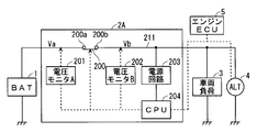
- FIG. 5 is a block diagram illustrating the configuration of the voltage measurement device 2C and the configuration around it.
- the same components as those described in the first embodiment are denoted by the same reference numerals, and the description thereof is omitted.
- the voltage measurement device 2C has a configuration in which a power storage device 206 and a step-up / down circuit 208 are added to the voltage measurement device 2A.
- the power storage device 206 is, for example, an electric double layer capacitor, and its capacitance is, for example, about several to several tens of F.
- the power storage devices 1 and 206 can be grasped as a first power storage device and a second power storage device, respectively.
- a bidirectional buck-boost circuit is adopted as the buck-boost circuit 208.
- the step-up / step-down circuit 208 is connected to the DC bus 211, and the storage device 206 is connected to the DC bus 211 via the step-up / step-down circuit 208.
- the conversion of the voltage between power storage device 206 and DC bus 211 is performed by step-up / step-down circuit 208.
- the step-up / step-down circuit 208 enables either charging from the DC bus 211 to the power storage device 206 or discharging from the power storage device 206 to the DC bus 211.
- the discharge can be employed for either the power supply from the storage device 206 to the vehicle load 3 or the power supply to the power supply circuit 203.
- the voltage measuring unit 202 measures the voltage Vb as in the first embodiment. Therefore, the voltage measuring device 2C can also execute the flowchart shown in FIG. 2 similarly to the voltage measuring device 2A, whereby the measurement of the open circuit voltage of the storage device 1 causes the shortage of electric power while the vehicle is traveling. Is avoided.
- the alternator 4 does not generate power, but it is necessary to supply power to the vehicle load 3.
- the current required for such power supply is called dark current, and is required for wireless communication such as the function of opening a door wirelessly.
- dark current is obtained by discharge of power storage device 1. Therefore, when the relay 200 is opened and the open circuit voltage is measured, this dark current is interrupted. Moreover, power is not supplied from the alternator 4 to the power supply circuit 203. Therefore, even if the relay 200 is opened to measure the open circuit voltage when the vehicle is stopped, the control circuit 204 does not operate.
- the open circuit voltage of the storage device 1 is measured without blocking the dark current even when the vehicle is stopped.
- the engine ECU 5 shown in FIG. 1 for instructing the generated voltage to the alternator 4 is omitted.
- FIG. 6 is a flowchart illustrating the operation of the voltage measurement device 2C according to the second embodiment, and shows control by the control circuit 204.
- Steps S301, S303, S304, S305, S307, and S308 are the same steps as steps S101, S103, S104, S105, S107, and S108 of FIG. 2, respectively.
- steps S302a and S302b are executed in place of step S102 of the first embodiment.
- control circuit 204 determines whether or not voltage Vc of power storage device 206 serving as the auxiliary power is normal. Similar to step S102, if the determination result is negative, step S308 is executed, and the control circuit 204 turns on (closes) the relay 200. Then, in step S309, power storage device 206 is charged from power storage device 1 via relay 200 and DC bus 211. On the other hand, if the determination result is affirmative, step S302 b is executed.
- control circuit 204 detects voltage Vc via step-up / step-down circuit 208.
- the voltage Vc is equal to or higher than the third threshold, the voltage of the auxiliary power supply is normal.
- the voltage Vc is lower than the third threshold, it is determined that the voltage is not normal.
- the third threshold is a threshold for the voltage Vc which can convert the voltage Vb to a voltage sufficient to allow the step-up / step-down circuit 208 to supply the dark current to the vehicle load 3 sufficiently. Since the detection of the voltage Vc is a known technique, the detailed description is omitted here.
- step S302 b since it is determined in step S302 a that the dark current is secured even if the relay 200 is turned off, the power storage device 206 is discharged via the step-up / step-down circuit 208. Since the dark current can be secured by execution of step S302 b, step S303 is executed, and the control circuit 204 turns off (opens) the relay 200.
- step S306 is executed instead of step S106 of the first embodiment.
- step S306 the same determination as in step S302a is performed. If the determination result is negative, steps S308 and S309 are executed. If the determination result is affirmative, step S307 is executed, and step S305 or steps S308 and S309 are executed as in step S107.
- control circuit 204 opens / closes between the ends 200 a and 200 b depending on whether the voltage Vc of the power storage device 206 is equal to or higher than the third threshold.
- the open circuit voltage can be measured even while the vehicle is stopped, and the dark current is secured. Ru.
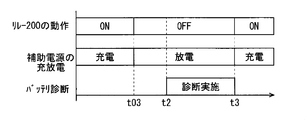
- FIG. 7 is a graph in which the horizontal axis represents time, and shows the operation of the relay 200, charging / discharging of the power storage device 206 (denoted as "auxiliary power supply” in the figure), and the state of battery diagnosis.
- step S302a At time t03, an affirmative determination is made in step S302a, steps S302b and S303 are executed, and the relay 200 is turned off (opened). Thereafter, steps S304, S302a, S302b, and S303 are repeatedly executed, and step S305 is executed at time t2. Thus, after step S303 is performed, the case where negative determination is not made by step S302a until step S305 is performed is illustrated.
- step S306 a negative determination is not made in step S306 until a positive determination is obtained in step S307.
- a positive determination is obtained in step S307, and the relay 200 is turned on (closed) by executing step S308.
- step S306 the battery determination is interrupted, the relay 200 is turned on (closed) by executing step S308, and the power storage device 206 is charged in step S309.
- power storage device 206 as an auxiliary power supply as described above, power is supplied to power supply circuit 203 even while the vehicle is parked, operation failure of control circuit 204 is avoided, and the open circuit voltage of power storage device 1 is measured. . Moreover, the dark current can be secured by adopting the determinations of steps S302a and S306a.
- the relay 200 be a normally closed type. Even in the case of the normally closed type, the above operation is not disturbed, and even if the power supply from the storage device 206 is insufficient to cause the control circuit 204 to malfunction, the storage device 1 is not connected via the closed relay 200. This is because the power supply circuit 203 is supplied with power, and the operation of the control circuit 204 is restored.
- step S106 whether the current flowing to the vehicle load 3 has increased may be adopted as the basis of the determination of step S106.
- the increase of the current causes a shortage of power supply to the vehicle load 3 when the relay 200 is open.
- step S108 is executed, and if the current does not increase, step S107 is executed.
- the ability of the step-up / step-down circuit 208 to convert the voltage Vc into the voltage Vb is preset.
- the first threshold may be set to K times the third threshold, and step S102 may be used instead for either of steps S302a and S306. That is, also in the second embodiment, by setting the first threshold as described above, the control circuit 204 closes the voltage between the ends 200a and 200b when the voltage Vb is lower than the first threshold. It is possible to close between the ends 200a and 200b when Vc is less than or equal to the third threshold.
- power storage device 206 may be incorporated in voltage measurement device 2C as illustrated in FIG. 5 or may be provided outside voltage measurement device 2C.
- the power storage device 206 and the voltage measurement device 2C are collectively a voltage measurement system that measures the open-circuit voltage of the power storage device 1.
- Voltage measuring devices 2A and 2C may be built in a relay box mounted on a vehicle, or may be provided between power storage device 1 and the relay box.
- each structure demonstrated by said each embodiment and each modification can be combined suitably, as long as there is no contradiction mutually.
- Power storage device (first power storage device) 2A voltage measuring device 2C voltage measuring device 3 vehicle load 4 alternator 200 relay 200a end (second end) 200b end (first end) 201 Voltage measurement unit (second voltage measurement unit) 202 Voltage Measurement Unit (First Voltage Measurement Unit) 203 power supply circuit 204 control circuit 206 power storage device (second power storage device) 208 Buck-Boost Circuit 211 DC Bus
Landscapes
- Engineering & Computer Science (AREA)
- Power Engineering (AREA)
- Mechanical Engineering (AREA)
- Chemical Kinetics & Catalysis (AREA)
- Electrochemistry (AREA)
- General Chemical & Material Sciences (AREA)
- Chemical & Material Sciences (AREA)
- Physics & Mathematics (AREA)
- General Physics & Mathematics (AREA)
- Manufacturing & Machinery (AREA)
- Secondary Cells (AREA)
- Charge And Discharge Circuits For Batteries Or The Like (AREA)
- Measurement Of Current Or Voltage (AREA)
- Tests Of Electric Status Of Batteries (AREA)
Abstract
The present invention avoids electric power shortages that occur during vehicle travel as a result of the measurement of the open-state voltage of an onboard power storage device. A voltage measurement device that comprises a relay, a first voltage measurement part, a second voltage measurement part, a power supply circuit, and a control circuit. The power supply circuit is indirectly connected to a direct-current bus. The first voltage measurement part measures a first voltage, which is applied to the power supply circuit. The relay is interposed between the direct-current bus and a power storage device. A first end of the relay is connected to the direct-current bus, and a second end of the relay is connected to the power storage device 1. The control circuit receives operating power from the power supply circuit and thereby controls the opening/closing of the relay. When the first voltage is at or below a first threshold value, the control circuit closes the first end and the second end. The second voltage measurement part measures a second voltage, which is applied to the second end, at least when the relay is open.
Description
この発明は、電圧測定装置に関し、特に車載用蓄電装置の開放時電圧を測定する技術に関する。
The present invention relates to a voltage measurement apparatus, and more particularly to a technology for measuring an open circuit voltage of an on-vehicle storage device.
車両に搭載される蓄電装置(いわゆるバッテリ、電気二重層キャパシタを含む)の診断において、内部抵抗の測定を利用することが知られている。例えば下記の特許文献1にはメインバッテリとサブバッテリとを併設し、サブバッテリで平滑コンデンサを充電する際の電流値及び電圧値から、サブバッテリの内部抵抗を測定する技術が開示されている。
It is known to use the measurement of internal resistance in the diagnosis of a power storage device (including a so-called battery and an electric double layer capacitor) mounted on a vehicle. For example, Patent Document 1 below discloses a technique in which a main battery and a sub battery are provided side by side, and the internal resistance of the sub battery is measured from the current value and the voltage value when charging the smoothing capacitor with the sub battery.
蓄電装置の診断には内部抵抗のみを用いるよりも、蓄電装置の開放時の電圧(開放時電圧)をも用いる方が、精度が高いことも知られている。しかし蓄電装置が搭載される車両が走行中であれば、蓄電装置は当該車両が備えるオルタネーターによって充電されるので、開放時電圧を測定するときにはオルタネーターから蓄電装置への充電経路を遮断する必要がある。
It is also known that using the voltage at the time of opening the storage device (opening voltage) is also more accurate than using only the internal resistance for diagnosing the storage device. However, if the vehicle on which the storage device is mounted is traveling, the storage device is charged by the alternator provided in the vehicle, so when measuring the open circuit voltage, it is necessary to shut off the charging path from the alternator to the storage device .
他方、車載される電気負荷に対する給電は、当該車両の走行中において、オルタネーターのみならず蓄電装置の放電電流も必要となる場合がある。そしてこの放電経路は上記の充電経路と共通する部分があるため、単に充電経路を遮断すると、電気負荷への給電が十分に行われない可能性がある。
On the other hand, power supply to the on-board electrical load may require not only the alternator but also the discharge current of the storage device while the vehicle is traveling. And since this discharge path has a common part with the above-mentioned charge path, if the charge path is merely shut off, there is a possibility that the electric load is not sufficiently fed.
そこで、本発明は、車載された蓄電装置の開放時電圧の測定によって車両の走行中の電力が不足することを回避する技術を提供することを目的とする。
Then, this invention aims at providing the technique which avoids that the electric power in driving | running | working of a vehicle runs short by measurement of the open time voltage of the electrical storage apparatus carried in-vehicle.
電圧測定装置は、車両に搭載された発電機及び車両負荷に接続される直流バスに間接的に接続される第1蓄電装置の開放時電圧を測定する。電圧測定装置は、前記直流バスに接続された電源回路と、前記電源回路に印加される第1電圧を測定する第1電圧測定部と、前記直流バスと前記第1蓄電装置との間に介在し、前記直流バスに接続された第1端と、前記第1蓄電装置に接続された第2端とを有するリレーと、前記電源回路から動作電力を受け、前記リレーの開閉を制御し、前記第1電圧が第1閾値以下のときに前記第1端と前記第2端との間をクローズする制御回路と、前記第2端に印加される第2電圧を、少なくとも前記リレーが開放状態のときに測定する第2電圧測定部とを備える。
The voltage measurement device measures an open circuit voltage of a first power storage device indirectly connected to a generator mounted on the vehicle and a DC bus connected to the vehicle load. The voltage measurement device includes a power supply circuit connected to the DC bus, a first voltage measurement unit that measures a first voltage applied to the power supply circuit, and an intervening unit between the DC bus and the first power storage device. A relay having a first end connected to the DC bus and a second end connected to the first power storage device, and receiving operating power from the power supply circuit to control the opening and closing of the relay; A control circuit that closes between the first end and the second end when a first voltage is less than a first threshold, and a second voltage applied to the second end, at least the relay is open And a second voltage measuring unit that measures the time.
車載された蓄電装置の開放時電圧の測定によって車両の走行中の電力が不足することは回避される。
By measuring the open circuit voltage of the on-board power storage device, shortage of electric power while the vehicle is traveling can be avoided.
{第1実施形態}
第1実施形態に係る電圧測定装置2Aについて説明する。図1は電圧測定装置2Aの構成及びその周辺の構成を例示するブロック図である。電圧測定装置2Aは車載される蓄電装置1(図中「BAT」と表記)の開放時電圧を測定する機能を担う。蓄電装置1は、直流バス211を介してオルタネーター4(図中「ALT」と表記)に接続される。オルタネーター4は、エンジン(不図示)の回転によって発電する車載用の発電機として機能し、直流バス211を充電経路として蓄電装置1を充電する。通常、直流バス211には正電位が引加される。但しオルタネーター4が発電する電圧(発電電圧)は、エンジンECU(エレクトロニックコントロールユニット)5によって所定の電圧値となるように制御される。 First Embodiment
Thevoltage measurement device 2A according to the first embodiment will be described. FIG. 1 is a block diagram illustrating the configuration of the voltage measurement device 2A and the configuration around it. The voltage measurement device 2A has a function of measuring the open circuit voltage of the power storage device 1 (indicated as "BAT" in the figure) mounted on the vehicle. Power storage device 1 is connected to alternator 4 (denoted by “ALT” in the drawing) via DC bus 211. The alternator 4 functions as an on-vehicle generator that generates electric power by rotation of an engine (not shown), and charges the power storage device 1 with the DC bus 211 as a charging path. Usually, a positive potential is applied to the DC bus 211. However, the voltage (generated voltage) generated by the alternator 4 is controlled by the engine ECU (Electronic Control Unit) 5 to be a predetermined voltage value.
第1実施形態に係る電圧測定装置2Aについて説明する。図1は電圧測定装置2Aの構成及びその周辺の構成を例示するブロック図である。電圧測定装置2Aは車載される蓄電装置1(図中「BAT」と表記)の開放時電圧を測定する機能を担う。蓄電装置1は、直流バス211を介してオルタネーター4(図中「ALT」と表記)に接続される。オルタネーター4は、エンジン(不図示)の回転によって発電する車載用の発電機として機能し、直流バス211を充電経路として蓄電装置1を充電する。通常、直流バス211には正電位が引加される。但しオルタネーター4が発電する電圧(発電電圧)は、エンジンECU(エレクトロニックコントロールユニット)5によって所定の電圧値となるように制御される。 First Embodiment
The
蓄電装置1は例えば鉛蓄電池であってもよいし、電気二重層キャパシタであってもよい。車両負荷3は車載される電気負荷であり、直流バス211を介してオルタネーター4及び蓄電装置1のいずれからも給電され得る。
Power storage device 1 may be, for example, a lead storage battery or an electric double layer capacitor. The vehicle load 3 is an on-vehicle electrical load, and can be supplied with power from either the alternator 4 or the storage device 1 via the DC bus 211.
電圧測定装置2Aは、リレー200と、電源回路203と、電圧測定部201,202と、制御回路204とを備える。電源回路203は直流バス211に接続され、直流バス211から引加される電圧Vbを変換して制御回路204に与える。電圧Vbは電圧測定部202(図中で「電圧モニタB」と表記)によって測定される。
The voltage measurement device 2A includes a relay 200, a power supply circuit 203, voltage measurement units 201 and 202, and a control circuit 204. The power supply circuit 203 is connected to the DC bus 211, converts the voltage Vb supplied from the DC bus 211, and supplies the converted voltage Vb to the control circuit 204. The voltage Vb is measured by a voltage measurement unit 202 (indicated as “voltage monitor B” in the drawing).
リレー200は蓄電装置1と直流バス211との間に介在し、端200a,200bを有する。つまり蓄電装置1はリレー200を介して間接的に直流バス211に接続される。端200aは蓄電装置1に接続され、端200bは直流バス211に接続される。リレー200において、端200a,200bの間は、電圧Vbが第1閾値以下のときにクローズ(短絡)し、第2閾値以上のときにオープン(開放)する。但し、第1閾値は第2閾値よりも小さい。端200b,200aはそれぞれ第1端、第2端として把握することができる。
Relay 200 is interposed between power storage device 1 and DC bus 211, and has ends 200a and 200b. In other words, power storage device 1 is indirectly connected to DC bus 211 via relay 200. End 200 a is connected to power storage device 1, and end 200 b is connected to DC bus 211. In the relay 200, between the ends 200a and 200b, the voltage Vb is closed (short circuit) when the voltage Vb is lower than the first threshold and is opened (opened) when the voltage Vb is higher than the second threshold. However, the first threshold is smaller than the second threshold. The ends 200b and 200a can be grasped as a first end and a second end, respectively.
制御回路204(図中で「CPU」と表記)は電源回路203から動作電力を受けて動作する。制御回路204は公知のマイクロコンピュータを用いて実現することができる。制御回路204の具体的な第1の動作は、エンジンECU5に対し、オルタネーター4の発電電圧を制御させることである。具体的な第2の動作は、電圧測定部202に対して電源回路203に引加される電圧Vbを測定させ、その値に基づいてリレー200の開閉を制御することである。具体的な第3の動作は、端200aに印加される電圧Vaを、少なくともリレー200が開放状態のときに電圧測定部201(図中で「電圧モニタA」と表記)に測定させることである。電圧測定部202,201はそれぞれ第1電圧測定部、第2電圧測定部として把握することができる。
The control circuit 204 (denoted as “CPU” in the figure) operates by receiving operating power from the power supply circuit 203. The control circuit 204 can be realized using a known microcomputer. A specific first operation of the control circuit 204 is to make the engine ECU 5 control the generated voltage of the alternator 4. A specific second operation is to make the voltage measurement unit 202 measure the voltage Vb applied to the power supply circuit 203, and control the opening / closing of the relay 200 based on the value. A specific third operation is to cause the voltage measurement unit 201 (indicated as “voltage monitor A” in the drawing) to measure the voltage Va applied to the end 200 a at least when the relay 200 is in the open state. . The voltage measuring units 202 and 201 can be grasped as a first voltage measuring unit and a second voltage measuring unit, respectively.
図2は第1実施形態に係る電圧測定装置2Aの動作を例示するフローチャートであり、制御回路204による制御を示す。ステップS101~S104,S106,S108は上述の第2の動作に対応し、ステップS105,S107は上述の第3の動作に対応する。図2において「バッテリ診断」とは、蓄電装置1の診断を指す。当該診断には、蓄電装置1の開放時電圧の取得が含まれる。
FIG. 2 is a flowchart illustrating the operation of the voltage measurement device 2A according to the first embodiment, and shows control by the control circuit 204. Steps S101 to S104, S106, and S108 correspond to the above-described second operation, and steps S105 and S107 correspond to the above-described third operation. “Battery diagnosis” in FIG. 2 refers to a diagnosis of the power storage device 1. The diagnosis includes the acquisition of the open circuit voltage of the power storage device 1.
ステップS101では一旦、制御回路204によってリレー200がクローズ(ON)される。通常、蓄電装置1はオルタネーター4から直流バス211を介して充電され、直流バス211を介して車両負荷3へ放電するので、車両走行中はリレー200はクローズされている。ステップS101を省略してもよい。
In step S101, the relay 200 is closed (ON) by the control circuit 204 once. Normally, since power storage device 1 is charged from alternator 4 via DC bus 211 and discharged to vehicle load 3 via DC bus 211, relay 200 is closed while the vehicle is traveling. Step S101 may be omitted.
ステップS101の実行後、ステップS102において電圧Vbが第2閾値以上か否かが判断される。第2閾値は車両負荷3への給電が十分となる電圧値である。かかる電圧値は車両負荷3の特性から予め設定できる。電圧Vbはオルタネーター4が発電する電圧であり、これが車両負荷3への給電に対して余力があるか否かが判断されるので、図2ではステップS102において「発電電圧余力あり?」と表記した。当該判断が肯定的であれば(電圧Vbが第2閾値以上であれば)、ステップS103においてリレー200がオープン(OFF)される。これにより、蓄電装置1は車両負荷3、オルタネーター4から遮断され、充放電しなくなる。このようにして、蓄電装置1の開放時電圧(図において「OCV」と表記)の測定が可能となる。
After execution of step S101, it is determined in step S102 whether the voltage Vb is equal to or greater than a second threshold. The second threshold is a voltage value at which power supply to the vehicle load 3 is sufficient. The voltage value can be preset from the characteristics of the vehicle load 3. The voltage Vb is a voltage generated by the alternator 4 and it is determined whether or not there is enough power for power supply to the vehicle load 3. Therefore, in FIG. . If the determination is affirmative (if the voltage Vb is equal to or higher than the second threshold), the relay 200 is opened (turned off) in step S103. As a result, the power storage device 1 is disconnected from the vehicle load 3 and the alternator 4 and is not charged or discharged. In this manner, measurement of the open circuit voltage (denoted as "OCV" in the figure) of the power storage device 1 becomes possible.
ステップS102において判断が否定的であれば(電圧Vbが第2閾値未満であれば)、ステップS108においてリレー200がクローズされる。これは、リレー200がオープンして開放時電圧の測定を開始すると、蓄電装置1から車両負荷3への給電がなくなることによって、車両負荷3への給電が不足することが予測されるからである。かかる給電不足を回避するため、ステップS102という判断工程が設けられる。
If the determination in step S102 is negative (if the voltage Vb is less than the second threshold), the relay 200 is closed in step S108. This is because when the relay 200 is opened and measurement of the open time voltage is started, it is predicted that power supply to the vehicle load 3 will be insufficient due to the absence of power supply from the storage device 1 to the vehicle load 3 . In order to avoid such power shortage, a determination step of step S102 is provided.
開放時電圧は、具体的には、リレー200がオープンのときに、電圧測定部201が測定する電圧Vaである。もちろん、電圧測定部201は、リレー200がクローズのときに電圧Vaを測定してもよいが、少なくともリレー200がオープンのときには電圧Vaを測定する。
Specifically, the open circuit voltage is a voltage Va measured by the voltage measurement unit 201 when the relay 200 is open. Of course, the voltage measurement unit 201 may measure the voltage Va when the relay 200 is closed, but at least when the relay 200 is open, it measures the voltage Va.
但し、蓄電装置1の開放時電圧は、特に蓄電装置1に鉛蓄電池のような化学電池が採用された場合、安定するまでに時間がかかる。よってステップS104において開放時電圧が安定したと判断されてから、ステップS105においてバッテリ診断が行われる。これは電圧Vaの測定を含む。
However, the open circuit voltage of the storage device 1 takes time to be stabilized particularly when a chemical battery such as a lead storage battery is adopted for the storage device 1. Therefore, after it is determined in step S104 that the open circuit voltage is stable, battery diagnosis is performed in step S105. This includes the measurement of the voltage Va.
ステップS104では、電圧Vaの変動が所定範囲に収まることをもって開放時電圧が安定したと判断してもよい。ステップS103によってリレー200がオープンとなってから、開放時電圧が安定するのに必要と想定される所定の時間が経過したことをもって、開放時電圧が安定したと判断してもよい。
In step S104, it may be determined that the open circuit voltage is stable when the fluctuation of the voltage Va falls within a predetermined range. After the relay 200 is opened in step S103, it may be determined that the open circuit voltage is stabilized when a predetermined time assumed to be necessary for the open circuit voltage to stabilize has elapsed.
ステップS104の判断が否定的(開放時電圧が安定していないという判断)であれば、ステップS102が再び実行され、開放時電圧の電圧Vbが第2閾値以上であるか否かが判断される。このように開放時電圧が安定するのを待機している間でも、ステップS102が再び実行されることにより、車両負荷3への給電不足が回避される。
If the determination in step S104 is negative (determination that the open circuit voltage is not stable), step S102 is executed again, and it is determined whether the open circuit voltage Vb is greater than or equal to the second threshold. . As described above, even while waiting for the open-time voltage to stabilize, step S102 is executed again, whereby the shortage of power supply to the vehicle load 3 is avoided.
同様に、ステップS105によってバッテリ診断を開始した後も、ステップS106によって電圧Vbが第1閾値よりも大きいか否かが判断される。第1閾値は車両負荷3への給電に必要な電圧値である。かかる電圧値は車両負荷3の特性から予め設定できる。バッテリ診断中に電圧Vbが第1閾値以下になれば、バッテリ診断を中止し、蓄電装置1から車両負荷3への給電を可能とすべくリレー200をクローズする。つまり、ステップS106の判断結果が否定的であれば、ステップS108が実行される。
Similarly, after the battery diagnosis is started in step S105, it is determined in step S106 whether the voltage Vb is larger than the first threshold. The first threshold is a voltage value required to supply power to the vehicle load 3. The voltage value can be preset from the characteristics of the vehicle load 3. If the voltage Vb falls below the first threshold during battery diagnosis, the battery diagnosis is stopped, and the relay 200 is closed to enable power supply from the storage device 1 to the vehicle load 3. That is, if the determination result of step S106 is negative, step S108 is executed.
バッテリ診断中に電圧Vbが第1閾値よりも大きな値を維持していれば、ステップS106の判断は肯定的となり、ステップS107においてバッテリ診断が終了したか否かが判断される。これは蓄電装置1の診断が、開放時電圧の電圧Vaのみならず、例えば既に取得されていた蓄電装置1の内部抵抗を用いた総合的な判断を必要とするため、必ずしも電圧Vaの取得のみで診断が終了しないことに鑑みて設けられた工程である。ステップS107の判断結果が否定的であれば(バッテリ診断が終了していなければ)ステップS105,S106が繰り返し実行される。このようにバッテリ診断時でも、ステップS106が再び実行されることにより、車両負荷3への給電不足が回避される。
If voltage Vb maintains a value larger than the first threshold during battery diagnosis, the determination in step S106 is affirmative, and in step S107, it is determined whether the battery diagnosis has ended. This is because the diagnosis of the storage device 1 requires not only the voltage Va of the open circuit voltage but also a comprehensive judgment using, for example, the internal resistance of the storage device 1 which has already been acquired, so that only the acquisition of the voltage Va is necessarily required. Step is provided in view of the fact that the diagnosis is not completed. If the determination result of step S107 is negative (if the battery diagnosis is not completed), steps S105 and S106 are repeatedly executed. As described above, even at the battery diagnosis time, the shortage of the power supply to the vehicle load 3 is avoided by executing step S106 again.
ステップS107の判断結果が肯定的であれば(バッテリ診断が終了していれば)、蓄電装置1への充放電を可能にするため、ステップS108においてリレー200がクローズ(ON)される。
If the determination result in step S107 is affirmative (if the battery diagnosis is completed), relay 200 is closed (ON) in step S108 in order to enable charging / discharging of power storage device 1.
このように第1閾値を用いて走行中の車両負荷3への給電を優先するので、蓄電装置1の開放時電圧の測定によって車両の走行中の電力が不足することが回避される。
As described above, priority is given to the power supply to the traveling vehicle load 3 using the first threshold, so that the shortage of the power during traveling of the vehicle can be avoided by the measurement of the open time voltage of the storage device 1.
以下、上記の動作を時間的推移の観点で説明する。図3及び図4はいずれも横軸に時間をとり、電圧Vb、リレー200の動作、バッテリ診断の状況を示すグラフである。但し図3は診断が中断されない場合を、図4は診断が中断される場合を、それぞれ示す。
Hereinafter, the above operation will be described in terms of time transition. FIGS. 3 and 4 are graphs in which time is plotted on the horizontal axis, and the voltage Vb, the operation of the relay 200, and the state of battery diagnosis are shown. However, FIG. 3 shows the case where the diagnosis is not interrupted, and FIG. 4 shows the case where the diagnosis is interrupted.
図3、図4のいずれの場合でも時刻t01において、上述の第1の動作に対応した事象が発生する。具体的には制御回路204の制御のもと、エンジンECU5がオルタネーター4に対して所定の電圧値Vb0(>0)で発電するように指示する。これにより、電圧Vbは上昇し、電圧値Vb0に至る。電圧Vbが第2閾値に至るまでは、ステップS102,S108が実行される。第2閾値は電圧値Vb0以下に、例えば電圧値Vb0に設定される。
In any case of FIG. 3 and FIG. 4, an event corresponding to the above-described first operation occurs at time t01. Specifically, under the control of the control circuit 204, the engine ECU 5 instructs the alternator 4 to generate power at a predetermined voltage value Vb0 (> 0). As a result, the voltage Vb rises and reaches the voltage value Vb0. Steps S102 and S108 are performed until the voltage Vb reaches the second threshold. The second threshold is set to a voltage value Vb0 or less, for example, to the voltage value Vb0.
図3、図4のいずれの場合でも、時刻t1までに電圧Vbが電圧値Vb0に至り、時刻t1でステップS103が実行される。これによりリレー200はOFF(オープン)する。その後、ステップS104,S102,S103が繰り返し実行され、時刻t2においてステップS105が実行される。このように図3、図4のいずれの場合でも、ステップS103が実行された後はステップS105が実行されるまで、電圧Vbは第2閾値未満とはならなかった場合を例示する。
In either case of FIGS. 3 and 4, the voltage Vb reaches the voltage value Vb0 by time t1, and step S103 is executed at time t1. Thus, the relay 200 is turned off (opened). Thereafter, steps S104, S102, and S103 are repeatedly executed, and step S105 is executed at time t2. Thus, in any case of FIG. 3 and FIG. 4, after step S103 is performed, the case where the voltage Vb does not become less than a 2nd threshold value is illustrated until step S105 is performed.
図3ではステップS107で肯定的な判断が得られるまでの間、電圧Vbが電圧値Vb0を維持し、(第2閾値よりも小さな)第1閾値以下にはならなかった場合を示す。この場合ステップS106の判断結果は否定的となることはない。時刻t3においてステップS107で肯定的な判断が得られ、ステップS108が実行されることによりリレー200はON(クローズ)する。
FIG. 3 shows the case where the voltage Vb maintains the voltage value Vb0 and does not fall below the first threshold (which is smaller than the second threshold) until a positive determination is obtained in step S107. In this case, the determination result of step S106 will not be negative. At time t3, a positive determination is obtained in step S107, and the relay 200 is turned on (closed) by executing step S108.
図4では第1閾値として値(Vb0-ΔV)(但しΔV>0)を採用した場合が例示される。ステップS105~S107が繰り返し実行されている途中で、電圧Vbが低下し、時刻t4において第1閾値に達する。これによりステップS106の判断結果が否定的となり、ステップS108によってリレー200はON(クローズ)する。そしてステップS107で肯定的な判断が得られる前にステップS108が実行されたので、バッテリ診断は中断される。
FIG. 4 exemplifies a case where a value (Vb 0 −ΔV) (where ΔV> 0) is adopted as the first threshold. While steps S105 to S107 are repeatedly executed, the voltage Vb decreases and reaches the first threshold at time t4. As a result, the determination result in step S106 becomes negative, and the relay 200 is turned on (closed) in step S108. And since step S108 was performed before an affirmative judgment is obtained by step S107, battery diagnosis is interrupted.
なお、リレー200はノーマリークローズ形であることが望ましい。ノーマリークローズ形であっても上記の動作は妨げられない。バッテリ診断の途中のリレー200がオープンの状態において、オルタネーター4の発電能力が低下、あるいは更に不全となった場合、あるいは電源回路203の機能が低下、あるいは更に不全となった場合、ノーマリークローズ形のリレー200はクローズするので、車両負荷3への給電に蓄電装置1を利用することができる。これは走行中の車両負荷3への給電を妨げない観点で望ましい。
The relay 200 is desirably a normally closed type. Even in the case of the normally closed type, the above operation is not hindered. When relay 200 in the middle of battery diagnosis is in an open state, if the power generation capacity of alternator 4 is reduced or further fails, or if the function of power supply circuit 203 is reduced or further failed, a normally closed type Since the relay 200 is closed, the power storage device 1 can be used to supply power to the vehicle load 3. This is desirable from the viewpoint of not interfering with the power supply to the vehicle load 3 during traveling.
{第2実施形態}
第2実施形態に係る電圧測定装置2Cについて説明する。図5は、電圧測定装置2Cの構成及びその周辺の構成を例示するブロック図である。なお、本実施形態の説明において、第1実施形態で説明したものと同様の構成要素については同一符号を付してその説明を省略する。 Second Embodiment
A voltage measurement device 2C according to a second embodiment will be described. FIG. 5 is a block diagram illustrating the configuration of the voltage measurement device 2C and the configuration around it. In the description of the present embodiment, the same components as those described in the first embodiment are denoted by the same reference numerals, and the description thereof is omitted.
電圧測定装置2Cは電圧測定装置2Aに対して蓄電装置206及び昇降圧回路208を追加した構成を有している。蓄電装置206は例えば電気二重層キャパシタであり、例えばその静電容量は数~十数F程度である。蓄電装置1,206はそれぞれ第1蓄電装置、第2蓄電装置として把握することができる。昇降圧回路208には例えば双方向昇降圧回路が採用される。昇降圧回路208は直流バス211に接続され、蓄電装置206は昇降圧回路208を介して直流バス211に接続される。蓄電装置206と直流バス211との間の電圧の変換は、昇降圧回路208によって行われる。
The voltage measurement device 2C has a configuration in which a power storage device 206 and a step-up / down circuit 208 are added to the voltage measurement device 2A. The power storage device 206 is, for example, an electric double layer capacitor, and its capacitance is, for example, about several to several tens of F. The power storage devices 1 and 206 can be grasped as a first power storage device and a second power storage device, respectively. For example, a bidirectional buck-boost circuit is adopted as the buck-boost circuit 208. The step-up / step-down circuit 208 is connected to the DC bus 211, and the storage device 206 is connected to the DC bus 211 via the step-up / step-down circuit 208. The conversion of the voltage between power storage device 206 and DC bus 211 is performed by step-up / step-down circuit 208.
制御回路204の制御のもと、昇降圧回路208は直流バス211から蓄電装置206への充電、及び蓄電装置206から直流バス211への放電のいずれをも可能とする。かかる放電は、蓄電装置206から車両負荷3への給電及び電源回路203への給電のいずれにも採用できる。
Under control of the control circuit 204, the step-up / step-down circuit 208 enables either charging from the DC bus 211 to the power storage device 206 or discharging from the power storage device 206 to the DC bus 211. The discharge can be employed for either the power supply from the storage device 206 to the vehicle load 3 or the power supply to the power supply circuit 203.
電圧測定部202は、第1実施形態と同様に、電圧Vbを測定する。よって電圧測定装置2Cも電圧測定装置2Aと同様に、図2に示されたフローチャートを実行することができ、以て蓄電装置1の開放時電圧の測定によって車両の走行中の電力が不足することは回避される。
The voltage measuring unit 202 measures the voltage Vb as in the first embodiment. Therefore, the voltage measuring device 2C can also execute the flowchart shown in FIG. 2 similarly to the voltage measuring device 2A, whereby the measurement of the open circuit voltage of the storage device 1 causes the shortage of electric power while the vehicle is traveling. Is avoided.
さて、車両が停車している間はオルタネーター4は発電しないが、車両負荷3に給電する必要がある。このような給電に必要な電流は暗電流といわれ、例えば無線でドアを開扉する機能のような無線通信に必要とされる。通常、暗電流は蓄電装置1の放電によって得られる。よってリレー200をオープンにして開放時電圧を測定すると、この暗電流を遮断してしまうことになる。しかもオルタネーター4から電源回路203には給電されない。よって車両が停車している場合にリレー200をオープンにして開放時電圧を測定しようとしても、制御回路204は動作しない。
Now, while the vehicle is stopped, the alternator 4 does not generate power, but it is necessary to supply power to the vehicle load 3. The current required for such power supply is called dark current, and is required for wireless communication such as the function of opening a door wirelessly. Usually, dark current is obtained by discharge of power storage device 1. Therefore, when the relay 200 is opened and the open circuit voltage is measured, this dark current is interrupted. Moreover, power is not supplied from the alternator 4 to the power supply circuit 203. Therefore, even if the relay 200 is opened to measure the open circuit voltage when the vehicle is stopped, the control circuit 204 does not operate.
そこで第2実施形態では、車両が停車している場合にも暗電流を遮断せずに蓄電装置1の開放時電圧を測定する技術を示す。このような技術を説明するので、図5では、オルタネーター4に対して発電電圧を指示する(図1に示された)エンジンECU5を省略している。
Therefore, in the second embodiment, a technique is described in which the open circuit voltage of the storage device 1 is measured without blocking the dark current even when the vehicle is stopped. In order to explain such a technique, in FIG. 5, the engine ECU 5 (shown in FIG. 1) for instructing the generated voltage to the alternator 4 is omitted.
図6は第2実施形態に係る電圧測定装置2Cの動作を例示するフローチャートであり、制御回路204による制御を示す。ステップS301,S303,S304,S305,S307,S308は、それぞれ図2のステップS101,S103,S104,S105,S107,S108と同じ工程である。
FIG. 6 is a flowchart illustrating the operation of the voltage measurement device 2C according to the second embodiment, and shows control by the control circuit 204. Steps S301, S303, S304, S305, S307, and S308 are the same steps as steps S101, S103, S104, S105, S107, and S108 of FIG. 2, respectively.
第2実施形態では、第1実施形態のステップS102に代替してステップS302a,S302bが実行される。ステップS302aにおいて、制御回路204は第4の動作として、補助電源たる蓄電装置206の電圧Vcが正常であるか否かを判断する。ステップS102と類似して、その判断結果が否定的であればステップS308が実行され、制御回路204がリレー200をON(クローズ)する。そしてステップS309により蓄電装置1からリレー200、直流バス211を介して蓄電装置206が充電される。他方、当該判断結果が肯定的であればステップS302bが実行される。
In the second embodiment, steps S302a and S302b are executed in place of step S102 of the first embodiment. In step S302a, as a fourth operation, control circuit 204 determines whether or not voltage Vc of power storage device 206 serving as the auxiliary power is normal. Similar to step S102, if the determination result is negative, step S308 is executed, and the control circuit 204 turns on (closes) the relay 200. Then, in step S309, power storage device 206 is charged from power storage device 1 via relay 200 and DC bus 211. On the other hand, if the determination result is affirmative, step S302 b is executed.
ステップS302aでは具体的には、制御回路204が昇降圧回路208を介して電圧Vcを検出する。そして電圧Vcが第3閾値以上であれば補助電源の電圧は正常であり、第3閾値未満であれば正常ではないと判断される。第3閾値は、昇降圧回路208が電圧Vcを、車両負荷3への暗電流の供給を十分に行える電圧にまで電圧Vbを変換しうる、電圧Vcに対する閾値である。電圧Vcの検出は周知の技術であるので、ここでは詳細な説明を省略する。
Specifically, in step S302a, control circuit 204 detects voltage Vc via step-up / step-down circuit 208. When the voltage Vc is equal to or higher than the third threshold, the voltage of the auxiliary power supply is normal. When the voltage Vc is lower than the third threshold, it is determined that the voltage is not normal. The third threshold is a threshold for the voltage Vc which can convert the voltage Vb to a voltage sufficient to allow the step-up / step-down circuit 208 to supply the dark current to the vehicle load 3 sufficiently. Since the detection of the voltage Vc is a known technique, the detailed description is omitted here.
ステップS302bでは、ステップS302aによってリレー200をオフしても暗電流が確保されると判断されたので、昇降圧回路208を介して蓄電装置206を放電する。ステップS302bの実行により暗電流を確保できるので、ステップS303が実行され、制御回路204がリレー200をOFF(オープン)する。
In step S302 b, since it is determined in step S302 a that the dark current is secured even if the relay 200 is turned off, the power storage device 206 is discharged via the step-up / step-down circuit 208. Since the dark current can be secured by execution of step S302 b, step S303 is executed, and the control circuit 204 turns off (opens) the relay 200.
第2実施形態では、ステップS305でバッテリ診断が実行された後、第1実施形態のステップS106に代替してステップS306が実行される。ステップS306ではステップS302aと同じ判断が行われ、判断結果が否定的であればステップS308,S309が実行される。判断結果が肯定的であればステップS307が実行され、ステップS107と同様にステップS305あるいはステップS308,S309が実行される。
In the second embodiment, after the battery diagnosis is executed in step S305, step S306 is executed instead of step S106 of the first embodiment. In step S306, the same determination as in step S302a is performed. If the determination result is negative, steps S308 and S309 are executed. If the determination result is affirmative, step S307 is executed, and step S305 or steps S308 and S309 are executed as in step S107.
このように制御回路204は端200a,200bの間を、蓄電装置206の電圧Vcが第3閾値以上であるか否かに応じて、それぞれオープン/クローズする。以上のようにして、図6のフローチャートでは、補助電源電圧が正常であると判断される値を第3閾値として採用することにより、停車中でも開放時電圧の測定ができ、しかも暗電流が確保される。
As described above, the control circuit 204 opens / closes between the ends 200 a and 200 b depending on whether the voltage Vc of the power storage device 206 is equal to or higher than the third threshold. As described above, in the flowchart of FIG. 6, by using the value at which the auxiliary power supply voltage is determined to be normal as the third threshold, the open circuit voltage can be measured even while the vehicle is stopped, and the dark current is secured. Ru.
以下、上記の動作を時間的推移の観点で説明する。図7は横軸に時間をとり、リレー200の動作、蓄電装置206(図中「補助電源」と表記)の充放電、バッテリ診断の状況を示すグラフである。
Hereinafter, the above operation will be described in terms of time transition. FIG. 7 is a graph in which the horizontal axis represents time, and shows the operation of the relay 200, charging / discharging of the power storage device 206 (denoted as "auxiliary power supply" in the figure), and the state of battery diagnosis.
時刻t03において、ステップS302aで肯定的判断がなされ、ステップS302b,S303が実行され、リレー200はOFF(オープン)する。その後、ステップS304,S302a,S302b,S303が繰り返し実行され、時刻t2においてステップS305が実行される。このように、ステップS303が実行された後は、ステップS305が実行されるまでステップS302aで否定的判断はなされなかった場合が例示される。
At time t03, an affirmative determination is made in step S302a, steps S302b and S303 are executed, and the relay 200 is turned off (opened). Thereafter, steps S304, S302a, S302b, and S303 are repeatedly executed, and step S305 is executed at time t2. Thus, after step S303 is performed, the case where negative determination is not made by step S302a until step S305 is performed is illustrated.
またステップS307で肯定的な判断が得られるまでの間、ステップS306で否定的判断がなされなかった場合を示す。時刻t3においてステップS307で肯定的な判断が得られ、ステップS308が実行されることによりリレー200はON(クローズ)する。
Also, a case is shown where a negative determination is not made in step S306 until a positive determination is obtained in step S307. At time t3, a positive determination is obtained in step S307, and the relay 200 is turned on (closed) by executing step S308.
もちろん、ステップS306で否定的判断がなされれば、バッテリ判断は中断され、ステップS308が実行されることによりリレー200はON(クローズ)し、ステップS309によって蓄電装置206が充電される。
Of course, if a negative determination is made in step S306, the battery determination is interrupted, the relay 200 is turned on (closed) by executing step S308, and the power storage device 206 is charged in step S309.
このように蓄電装置206を補助電源として用いることにより、車両が駐車中であっても電源回路203へ給電され、制御回路204の動作不全を回避し、蓄電装置1の開放時電圧が測定される。しかもステップS302a,S306aの判断を採用することにより、暗電流を確保できる。
By using power storage device 206 as an auxiliary power supply as described above, power is supplied to power supply circuit 203 even while the vehicle is parked, operation failure of control circuit 204 is avoided, and the open circuit voltage of power storage device 1 is measured. . Moreover, the dark current can be secured by adopting the determinations of steps S302a and S306a.
本実施形態においてもリレー200はノーマリークローズ形であることが望ましい。ノーマリークローズ形であっても上記の動作は妨げられないし、もしも蓄電装置206からの給電が不足して制御回路204の動作不全が発生したとしても、クローズしたリレー200を介して蓄電装置1から電源回路203に給電され、ひいては制御回路204の動作を復活させるからである。
Also in the present embodiment, it is desirable that the relay 200 be a normally closed type. Even in the case of the normally closed type, the above operation is not disturbed, and even if the power supply from the storage device 206 is insufficient to cause the control circuit 204 to malfunction, the storage device 1 is not connected via the closed relay 200. This is because the power supply circuit 203 is supplied with power, and the operation of the control circuit 204 is restored.
{変形例}
第1実施形態において、ステップS106の判断の根拠として、車両負荷3に流れる電流が増加したか否かを採用してもよい。かかる電流の増大はリレー200がオープンしているときの車両負荷3への給電不足を招来するからである。この場合、当該電流が増加したらステップS108が実行され、増加していなければステップS107が実行される。 {Modification}
In the first embodiment, whether the current flowing to the vehicle load 3 has increased may be adopted as the basis of the determination of step S106. The increase of the current causes a shortage of power supply to the vehicle load 3 when therelay 200 is open. In this case, if the current increases, step S108 is executed, and if the current does not increase, step S107 is executed.
第1実施形態において、ステップS106の判断の根拠として、車両負荷3に流れる電流が増加したか否かを採用してもよい。かかる電流の増大はリレー200がオープンしているときの車両負荷3への給電不足を招来するからである。この場合、当該電流が増加したらステップS108が実行され、増加していなければステップS107が実行される。 {Modification}
In the first embodiment, whether the current flowing to the vehicle load 3 has increased may be adopted as the basis of the determination of step S106. The increase of the current causes a shortage of power supply to the vehicle load 3 when the
第2実施形態において、昇降圧回路208が電圧Vcを電圧Vbへ変換する能力は予め設定される。この変換倍率をK(>0)とすると、第1閾値を第3閾値のK倍に設定して、ステップS302a,S306のいずれについても、ステップS102を代わりに用いることもできる。つまり、第2実施形態においても、上記のように第1閾値を設定することにより、制御回路204は、電圧Vbが第1閾値以下のときに端200a,200bの間をクローズすることにより、電圧Vcが第3閾値以下のときに端200a,200bの間をクローズすることを実現できる。
In the second embodiment, the ability of the step-up / step-down circuit 208 to convert the voltage Vc into the voltage Vb is preset. Assuming that the conversion magnification is K (> 0), the first threshold may be set to K times the third threshold, and step S102 may be used instead for either of steps S302a and S306. That is, also in the second embodiment, by setting the first threshold as described above, the control circuit 204 closes the voltage between the ends 200a and 200b when the voltage Vb is lower than the first threshold. It is possible to close between the ends 200a and 200b when Vc is less than or equal to the third threshold.
第2実施形態において、蓄電装置206は、図5で例示されるように電圧測定装置2Cに内蔵されてもよいし、電圧測定装置2Cの外部に設けてもよい。また、蓄電装置206と電圧測定装置2Cとをまとめて、蓄電装置1の開放時電圧を測定する電圧測定システムであると考えることができる。
In the second embodiment, power storage device 206 may be incorporated in voltage measurement device 2C as illustrated in FIG. 5 or may be provided outside voltage measurement device 2C. In addition, it can be considered that the power storage device 206 and the voltage measurement device 2C are collectively a voltage measurement system that measures the open-circuit voltage of the power storage device 1.
電圧測定装置2A,2Cは、車両に搭載されるリレーボックスに内蔵してもよいし、蓄電装置1とリレーボックスとの間に設けてもよい。
Voltage measuring devices 2A and 2C may be built in a relay box mounted on a vehicle, or may be provided between power storage device 1 and the relay box.
なお、上記各実施形態及び各変形例で説明した各構成は、相互に矛盾しない限り適宜組み合わせることができる。
In addition, each structure demonstrated by said each embodiment and each modification can be combined suitably, as long as there is no contradiction mutually.
以上のようにこの発明は詳細に説明されたが、上記した説明は、すべての局面において、例示であって、この発明がそれに限定されるものではない。例示されていない無数の変形例が、この発明の範囲から外れることなく想定され得るものと解される。
As mentioned above, although this invention was explained in detail, the above-mentioned explanation is illustration in all the aspects, and this invention is not limited to it. It is understood that countless variations not illustrated are conceivable without departing from the scope of the present invention.
1 蓄電装置(第1蓄電装置)
2A 電圧測定装置
2C 電圧測定装置
3 車両負荷
4 オルタネーター
200 リレー
200a 端(第2端)
200b 端(第1端)
201 電圧測定部(第2電圧測定部)
202 電圧測定部(第1電圧測定部)
203 電源回路
204 制御回路
206 蓄電装置(第2蓄電装置)
208 昇降圧回路
211 直流バス 1 Power storage device (first power storage device)
2A voltage measuring device 2C voltage measuring device 3vehicle load 4 alternator 200 relay 200a end (second end)
200b end (first end)
201 Voltage measurement unit (second voltage measurement unit)
202 Voltage Measurement Unit (First Voltage Measurement Unit)
203power supply circuit 204 control circuit 206 power storage device (second power storage device)
208 Buck-Boost Circuit 211 DC Bus
2A 電圧測定装置
2C 電圧測定装置
3 車両負荷
4 オルタネーター
200 リレー
200a 端(第2端)
200b 端(第1端)
201 電圧測定部(第2電圧測定部)
202 電圧測定部(第1電圧測定部)
203 電源回路
204 制御回路
206 蓄電装置(第2蓄電装置)
208 昇降圧回路
211 直流バス 1 Power storage device (first power storage device)
2A voltage measuring device 2C voltage measuring device 3
200b end (first end)
201 Voltage measurement unit (second voltage measurement unit)
202 Voltage Measurement Unit (First Voltage Measurement Unit)
203
208 Buck-
Claims (7)
- 車両に搭載された発電機及び車両負荷に接続される直流バスに間接的に接続される第1蓄電装置の開放時電圧を測定する電圧測定装置であって、
前記直流バスに接続された電源回路と、
前記電源回路に印加される第1電圧を測定する第1電圧測定部と、
前記直流バスと前記第1蓄電装置との間に介在し、前記直流バスに接続された第1端と、前記第1蓄電装置に接続された第2端とを有するリレーと、
前記電源回路から動作電力を受け、前記リレーの開閉を制御し、前記第1電圧が第1閾値以下のときに前記第1端と前記第2端との間をクローズする制御回路と、
前記第2端に印加される第2電圧を、少なくとも前記リレーが開放状態のときに測定する第2電圧測定部と
を備える電圧測定装置。 A voltage measuring device for measuring an open circuit voltage of a first power storage device indirectly connected to a generator mounted on a vehicle and a DC bus connected to a vehicle load,
A power supply circuit connected to the DC bus;
A first voltage measurement unit configured to measure a first voltage applied to the power supply circuit;
A relay interposed between the DC bus and the first power storage device and having a first end connected to the DC bus and a second end connected to the first power storage device;
A control circuit that receives operating power from the power supply circuit and controls opening and closing of the relay, and closes between the first end and the second end when the first voltage is less than a first threshold;
And a second voltage measuring unit configured to measure a second voltage applied to the second end at least when the relay is in an open state. - 請求項1記載の電圧測定装置であって、
前記制御回路は、前記第1電圧が前記第1閾値よりも大きな第2閾値以上のときに前記第1端と前記第2端との間をオープンする、電圧測定装置。 The voltage measuring device according to claim 1,
The control circuit is configured to open between the first end and the second end when the first voltage is equal to or greater than a second threshold that is greater than the first threshold. - 請求項1記載の電圧測定装置であって、
前記直流バスに接続された昇降圧回路
を更に有し、
前記直流バスには前記昇降圧回路を介して第2蓄電装置も接続される、電圧測定装置。 The voltage measuring device according to claim 1,
It further comprises a buck-boost circuit connected to the DC bus,
A second power storage device is also connected to the DC bus via the step-up / step-down circuit. - 請求項3記載の電圧測定装置であって、
前記制御回路は前記第1端と前記第2端との間を、前記第2蓄電装置の電圧が第3閾値以上であるか否かに応じて、それぞれオープン/クローズする、電圧測定装置。 The voltage measuring device according to claim 3,
The control circuit opens / closes between the first end and the second end depending on whether the voltage of the second power storage device is equal to or higher than a third threshold. - 請求項1、請求項2、請求項3、請求項4のいずれか一項に記載の電圧測定装置であって、
前記リレーはノーマリークローズ形である、電圧測定装置。 A voltage measurement device according to any one of claims 1, 2, 3 and 4, wherein
The voltage measuring device is that the relay is normally closed. - 請求項3又は請求項4に記載の電圧測定装置と、
前記第2蓄電装置と
を備える電圧測定システム。 A voltage measurement device according to claim 3 or claim 4,
A voltage measurement system comprising the second power storage device. - 請求項6に記載の電圧測定システムであって、
前記リレーはノーマリークローズ形である、電圧測定システム。 The voltage measurement system according to claim 6, wherein
The voltage measurement system, wherein the relay is normally closed.
Priority Applications (2)
| Application Number | Priority Date | Filing Date | Title |
|---|---|---|---|
| CN201680066058.3A CN108352716B (en) | 2015-11-30 | 2016-11-25 | Voltage measurement device and voltage measurement system |
| US15/773,401 US10677851B2 (en) | 2015-11-30 | 2016-11-25 | Voltage measurement device, voltage measurement system |
Applications Claiming Priority (2)
| Application Number | Priority Date | Filing Date | Title |
|---|---|---|---|
| JP2015233025A JP6418141B2 (en) | 2015-11-30 | 2015-11-30 | Voltage measuring device, voltage measuring system |
| JP2015-233025 | 2015-11-30 |
Publications (1)
| Publication Number | Publication Date |
|---|---|
| WO2017094620A1 true WO2017094620A1 (en) | 2017-06-08 |
Family
ID=58797298
Family Applications (1)
| Application Number | Title | Priority Date | Filing Date |
|---|---|---|---|
| PCT/JP2016/085014 WO2017094620A1 (en) | 2015-11-30 | 2016-11-25 | Voltage measurement device, voltage measurement system |
Country Status (4)
| Country | Link |
|---|---|
| US (1) | US10677851B2 (en) |
| JP (1) | JP6418141B2 (en) |
| CN (1) | CN108352716B (en) |
| WO (1) | WO2017094620A1 (en) |
Families Citing this family (5)
| Publication number | Priority date | Publication date | Assignee | Title |
|---|---|---|---|---|
| JP6520665B2 (en) * | 2015-11-30 | 2019-05-29 | 株式会社オートネットワーク技術研究所 | Voltage measuring device, voltage measuring system |
| JP6750288B2 (en) * | 2016-04-15 | 2020-09-02 | 株式会社オートネットワーク技術研究所 | Relay device |
| US10549649B2 (en) * | 2017-11-10 | 2020-02-04 | GM Global Technology Operations LLC | Maximum current calculation and power prediction for a battery pack |
| JP6819719B2 (en) * | 2019-04-24 | 2021-01-27 | スズキ株式会社 | Vehicle power supply |
| KR20210042655A (en) | 2019-10-10 | 2021-04-20 | 주식회사 엘지화학 | Apparatus for controlling heating pad |
Citations (4)
| Publication number | Priority date | Publication date | Assignee | Title |
|---|---|---|---|---|
| JP2003291754A (en) * | 2002-04-01 | 2003-10-15 | Toyota Motor Corp | Electric power source for vehicle |
| JP2011230685A (en) * | 2010-04-28 | 2011-11-17 | Denso Corp | Electronic control device for vehicle |
| JP2013051823A (en) * | 2011-08-31 | 2013-03-14 | Toyota Industries Corp | Battery state monitoring system and method |
| JP2015020619A (en) * | 2013-07-19 | 2015-02-02 | 株式会社オートネットワーク技術研究所 | Vehicle power feed device |
Family Cites Families (11)
| Publication number | Priority date | Publication date | Assignee | Title |
|---|---|---|---|---|
| US4733100A (en) * | 1987-01-14 | 1988-03-22 | Fox Technology, Inc. | Automatic on/off circuit with time delay |
| JP2812066B2 (en) * | 1992-06-04 | 1998-10-15 | 三菱電機株式会社 | Power supply voltage switching device for vehicles |
| JP5094797B2 (en) * | 2009-08-07 | 2012-12-12 | 日立オートモティブシステムズ株式会社 | DC power supply smoothing capacitor discharge circuit |
| EP2781002B1 (en) * | 2011-11-15 | 2016-11-02 | Maxwell Technologies, Inc. | System and methods for managing a degraded state of a capacitor system |
| JP5477409B2 (en) * | 2012-03-12 | 2014-04-23 | 株式会社デンソー | Power system |
| JP5966583B2 (en) * | 2012-05-11 | 2016-08-10 | 日産自動車株式会社 | Power control device |
| JP5961854B2 (en) * | 2012-07-23 | 2016-08-02 | 株式会社明電舎 | Motor drive circuit |
| JP5983171B2 (en) * | 2012-08-10 | 2016-08-31 | 株式会社Gsユアサ | Switch failure diagnosis device, power storage device |
| JP5772781B2 (en) * | 2012-10-10 | 2015-09-02 | トヨタ自動車株式会社 | Vehicle, power supply system, and control method for power supply system |
| US20160016483A1 (en) * | 2013-04-03 | 2016-01-21 | Autonetworks Technologies, Ltd. | Control apparatus, power supply control apparatus, charge control method, charge control apparatus, and power supply apparatus for vehicles |
| US9970988B2 (en) * | 2015-11-20 | 2018-05-15 | Tabuchi Electric Co., Ltd. | Relay abnormality detection device and power conditioner |
-
2015
- 2015-11-30 JP JP2015233025A patent/JP6418141B2/en active Active
-
2016
- 2016-11-25 WO PCT/JP2016/085014 patent/WO2017094620A1/en active Application Filing
- 2016-11-25 CN CN201680066058.3A patent/CN108352716B/en active Active
- 2016-11-25 US US15/773,401 patent/US10677851B2/en active Active
Patent Citations (4)
| Publication number | Priority date | Publication date | Assignee | Title |
|---|---|---|---|---|
| JP2003291754A (en) * | 2002-04-01 | 2003-10-15 | Toyota Motor Corp | Electric power source for vehicle |
| JP2011230685A (en) * | 2010-04-28 | 2011-11-17 | Denso Corp | Electronic control device for vehicle |
| JP2013051823A (en) * | 2011-08-31 | 2013-03-14 | Toyota Industries Corp | Battery state monitoring system and method |
| JP2015020619A (en) * | 2013-07-19 | 2015-02-02 | 株式会社オートネットワーク技術研究所 | Vehicle power feed device |
Also Published As
| Publication number | Publication date |
|---|---|
| CN108352716B (en) | 2021-07-16 |
| JP6418141B2 (en) | 2018-11-07 |
| CN108352716A (en) | 2018-07-31 |
| JP2017103845A (en) | 2017-06-08 |
| US10677851B2 (en) | 2020-06-09 |
| US20180328993A1 (en) | 2018-11-15 |
Similar Documents
| Publication | Publication Date | Title |
|---|---|---|
| WO2017094620A1 (en) | Voltage measurement device, voltage measurement system | |
| JP6546617B2 (en) | Power distribution system | |
| JP6527906B2 (en) | Power distribution system | |
| CN108011433B (en) | Power storage device, power storage device monitoring system, storage medium, and power storage device control method | |
| US8823206B2 (en) | Power-supply control device | |
| US10916962B2 (en) | Dual energy store and dual charging source vehicle power supply system and vehicle drive system | |
| JP2019146305A (en) | Power supply system | |
| US10161992B2 (en) | Power supply apparatus, transport device including power supply apparatus, determination method of determining state of sensor detecting current value, and computer readable medium for determining state | |
| US20150203060A1 (en) | Power supply management system and power supply management method | |
| JP2009259762A (en) | Power source having a plurality of relays | |
| US20180326925A1 (en) | Charge/discharge device | |
| US20190305587A1 (en) | Vehicle backup device | |
| US11404899B2 (en) | Battery system and battery management device for cancelling polarization voltage by applying a reverse current | |
| WO2017068874A1 (en) | On-vehicle power source device | |
| JP6520665B2 (en) | Voltage measuring device, voltage measuring system | |
| JP7101506B2 (en) | Battery deterioration judgment device | |
| JP6220158B2 (en) | Relay diagnostic device | |
| JP6409635B2 (en) | Power storage system | |
| WO2022210441A1 (en) | Auxiliary power supply device and method for controlling auxiliary power supply device | |
| US20130241564A1 (en) | Method for Determining a Charge State of a Battery | |
| JP5411046B2 (en) | Vehicle battery management apparatus and current sensor offset detection method | |
| JP2015209126A (en) | Power supply device and control method therefor | |
| JP2024045998A (en) | vehicle power system | |
| CN109643906B (en) | Management device and power supply system | |
| JP2021114869A (en) | Power source system |
Legal Events
| Date | Code | Title | Description |
|---|---|---|---|
| 121 | Ep: the epo has been informed by wipo that ep was designated in this application |
Ref document number: 16870557 Country of ref document: EP Kind code of ref document: A1 |
|
| WWE | Wipo information: entry into national phase |
Ref document number: 15773401 Country of ref document: US |
|
| NENP | Non-entry into the national phase |
Ref country code: DE |
|
| 122 | Ep: pct application non-entry in european phase |
Ref document number: 16870557 Country of ref document: EP Kind code of ref document: A1 |