WO2017006426A1 - Système d'affichage, dispositif portable sur soi, et dispositif d'affichage vidéo - Google Patents
Système d'affichage, dispositif portable sur soi, et dispositif d'affichage vidéo Download PDFInfo
- Publication number
- WO2017006426A1 WO2017006426A1 PCT/JP2015/069498 JP2015069498W WO2017006426A1 WO 2017006426 A1 WO2017006426 A1 WO 2017006426A1 JP 2015069498 W JP2015069498 W JP 2015069498W WO 2017006426 A1 WO2017006426 A1 WO 2017006426A1
- Authority
- WO
- WIPO (PCT)
- Prior art keywords
- control information
- wearable device
- video
- unit
- display device
- Prior art date
Links
Images


Classifications
-
- G—PHYSICS
- G06—COMPUTING; CALCULATING OR COUNTING
- G06F—ELECTRIC DIGITAL DATA PROCESSING
- G06F3/00—Input arrangements for transferring data to be processed into a form capable of being handled by the computer; Output arrangements for transferring data from processing unit to output unit, e.g. interface arrangements
- G06F3/01—Input arrangements or combined input and output arrangements for interaction between user and computer
- G06F3/03—Arrangements for converting the position or the displacement of a member into a coded form
- G06F3/033—Pointing devices displaced or positioned by the user, e.g. mice, trackballs, pens or joysticks; Accessories therefor
- G06F3/0346—Pointing devices displaced or positioned by the user, e.g. mice, trackballs, pens or joysticks; Accessories therefor with detection of the device orientation or free movement in a 3D space, e.g. 3D mice, 6-DOF [six degrees of freedom] pointers using gyroscopes, accelerometers or tilt-sensors
Definitions
- the present invention relates to a display system, a wearable device, and a video display device, and more particularly to a technique effective for improving the operability of an image display device.
- Projectors are widely used as projection equipment for projecting monitor images on screens.
- As an indication technique of an instruction destination in a projector for example, a technique using a laser type pointer independent of a projector or a technique using a cursor image is widely used.
- the cursor image is output by superimposing the cursor image on the video by connecting an information device such as a personal computer or a smartphone storing the video to the projector.
- the pointer when a pointer is used, the pointer must be held in either the left or right hand, and the hand is blocked. Similarly, when moving the cursor on the cursor screen, the keys of the information device have to be operated, and the hands are blocked.
- Patent Document 1 recognizes a gesture operation of a human hand and updates the display position of the cursor. However, since there is no description other than the operation of moving the cursor, it cannot be expanded to other operations utilizing the projection function.
- the information device or the like when displaying the next page, the information device or the like must be operated, and the presenter's hand is blocked during the operation.
- the presenter's hand is blocked during the operation.
- the user at the time of presentation, as described above, there are many cases where the user possesses materials, tablets, and the like, and it is considered that the operation of the information device becomes difficult.
- An object of the present invention is to provide a technique capable of efficiently controlling an output video by a gesture operation in addition to a cursor movement operation.
- a typical display system includes a video display device and a wearable device capable of operating the video display device by communicating with the video display device.
- the wearable device includes a first communication unit, a displacement sensor, a contact detection unit, and a control information generation unit.
- the first communication unit communicates with the video display device.
- the displacement sensor detects the inclination of the wearable device and the displacement of the wearable device.
- the contact detection unit detects contact of an object.
- the control information generation unit generates control information to be transmitted to the video display device via the first communication unit.
- the video display device includes a video output unit, a second communication unit, and a video generation unit.
- the video output unit displays or projects the video.
- the second communication unit communicates with the wearable device.
- the video generation unit changes the content of the output video from the video output unit in accordance with control information received from the wearable device via the second communication unit.
- the wearable device control information generation unit controls the wearable device detected by the displacement sensor during a period in which contact detection is performed by the contact detection unit or a period after contact detection is performed by the contact detection unit. Information is generated, and the generated control information and the displacement of the wearable device detected by the displacement sensor are output from the first communication unit.
- the control information generated by the control information generation unit includes the first control information or the second control information, and the first control information changes the position of the cursor or pointer displayed in the output video of the video display device.
- the second control information is control information for controlling a video display device different from the first control information.
- the wearable device includes a vibration generating unit that vibrates the wearable device.
- the video display device indicates that the cursor or pointer has overlapped with the position from the second communication unit.
- the first notification information is transmitted to the communication unit of the wearable device.
- the vibration generating unit generates vibration when the communication unit of the wearable device receives the first notification information.
- the operability of the video display device can be improved.
- FIG. 10 is an explanatory diagram illustrating an example of a configuration of a projection device according to a second embodiment.
- FIG. 10 is an explanatory diagram illustrating an example of a configuration of a wearable information processing apparatus according to a second embodiment. It is a flowchart which shows an example of the process by the mounting
- the constituent elements are not necessarily indispensable unless otherwise specified and apparently essential in principle. Needless to say.
- the display system includes a projection device 1 shown in FIG. 1 and a wearable information processing device 2 shown in FIG. Further, the wearable information processing apparatus 2 can operate the projection apparatus 1 by communicating with the projection apparatus 1.
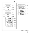
- FIG. 1 is an explanatory diagram showing an example of the configuration of the projection apparatus 1 according to the first embodiment.
- the projection device 1 that is a video display device includes an image input unit 101, a control unit 102, an output unit 103, a communication unit 104, and a storage unit 105.
- the projection apparatus 1 also includes a cursor position recognition function unit 111, an operable state recognition function unit 112, a superimposition determination function unit 113, a response function unit 114, an operation mode switching function unit 115, and an operation instruction recognition function unit 116.
- a cursor position recognition function unit 111 an operable state recognition function unit 112
- a superimposition determination function unit 113 a response function unit 114
- an operation mode switching function unit 115 an operation instruction recognition function unit 116.
- Each of these functional units is realized when the control unit 102 described later executes based on a program that is software, for example.
- each of the functional units described above is realized by software.
- each functional unit may be realized by hardware, part or all of them.
- hardware and software may be used in combination.
- the image input unit 101 serving as a video generation unit is a connection interface that can input video or audio signals from the outside or the inside.
- the image input unit 101 may be an RGB input terminal, an HDMI (High Definition Multimedia Interface) terminal, a USB (Universal Serial Bus) terminal, an SD card slot, or the like.
- RGB input terminal is a terminal that can input video.
- the HDMI terminal is a terminal corresponding to an interface standard such as digital video or audio, and inputs a moving image to an externally connected high-vision monitor or the like.
- the USB terminal is a connection terminal with an external device, and inputs a moving image to an external memory, for example.
- the SD card slot is a slot into which an SD memory card is inserted.
- the control unit 102 serving as a video generation unit includes a CPU (Central Processing Unit) that controls a communication unit 104 and functional units described later, a memory, peripheral devices, and the like. Realize the functions.
- CPU Central Processing Unit
- the output unit 103 serving as a video output unit has a function of displaying and outputting a video signal and an audio signal input via the image input unit 101.
- the output unit 103 is, for example, a projector that projects video or a direct-view display that outputs video and audio.
- the communication unit 104 is a communication module that receives an operation instruction of the projection apparatus 1 from another device and transmits a response thereof, and corresponds to, for example, Bluetooth communication.
- the communication between the projection apparatus 1 and the wearable information processing apparatus 2 shown in FIG. 2 is performed by Bluetooth communication, but the communication method is not limited to this, and other communication methods are used. May be.
- the storage unit 105 is an information storage medium and includes a semiconductor memory, an HDD (Hard Disc Drive), or the like.
- the storage unit 105 may be a fixed type that cannot be removed from the projection apparatus 1 or a removable type that can be removed.
- the storage unit 105 stores cursor position information 130, authentication information 131, gesture pattern information 132, input image information 133, and operable object information 134, which will be described later.
- the cursor position recognition function unit 111 reads the current cursor position information 130 stored in the storage unit 105.
- the operable state recognition function unit 112 determines whether the object on which the cursor is superimposed is operable. For example, operation information 1343 related to the object on which the cursor is superimposed is read from the storage unit 105, and when there is operation information 1343, it is determined that the operation is possible.
- the video generation unit superimposition determination function unit 113 determines whether or not the current cursor position information 130 is included in the set of position information 1341 constituting the operable object in the video displayed via the output unit 103. Determine.
- the response function unit 114 transmits advance notification information 1345, intermediate response information 1346, and final response information 1347 regarding the operation via the communication unit 104.
- the operation mode switching function unit 115 receives an instruction from the control unit 102 and switches the operation mode to the cursor operation mode or the gesture operation mode.
- the cursor operation mode is mainly intended to simply move the cursor image output via the output unit 103 or to select an operable object described later.
- the gesture operation mode includes switching of the input image information 133 output via the output unit 103, advance / retreat, and enlargement / reduction, and processing associated with an operable object image to be combined with the input image information 133.
- the main purpose is to instruct execution using gestures.
- the operation instruction recognition function unit 116 compares the gesture pattern information 132 stored in the storage unit 105 with the displacement information 221 and recognizes the gesture operation.
- the cursor position information 130 is a coordinate value representing the current position of the cursor projected and displayed via the output unit 103.
- the authentication information 131 is shared data for enabling communication between the projection apparatus 1 and the wearable information processing apparatus 2.
- the authentication information 131 is a password or PIN (Personal Identification ⁇ ⁇ Number) that can be input by the projection apparatus 1 or the wearable information processing apparatus 2. ) Indicates a number.
- the gesture pattern information 132 serving as operation pattern information is a set of gesture operations that can be recognized by an operation instruction recognition function unit 116 described later. For example, when a displacement in the right direction from the initial position can be detected, a function for controlling the projection apparatus 1 is assigned to each gesture operation, such as performing an operation to advance the projection image.
- the input image information 133 is a video or image input via the image input unit 101. This is an image that is a basis for generating a projection image that is output through the output unit 103 by superimposing a cursor image or the like.
- the operable object information 134 includes position information 1341 of the operable object, image information 1342 of the operable object, and operation information 1343 of the operable object, and a plurality of the operable object information 134 may be provided depending on the number of operable objects. it can.
- the position information 1341 of the manipulable object is a coordinate value indicating an area to which a specific operation execution instruction is assigned on the image projected via the output unit 103.
- this area is a polygon, it may be expressed as a set of coordinate values of points surrounding this area.
- the image information 1342 of the manipulable object is an image that visually indicates an area to which a specific operation execution instruction is assigned.
- the image input unit 101 may be superimposed on the video input and projected via the output unit 103, or the image information 1342 alone may be projected via the output unit 103.
- the operation information 1343 of the operable object includes execution information 1344, advance notification information 1345, intermediate response information 1346, and final response information 1347.
- the execution information 1344 is information representing processing to be executed on the control unit 102.
- the execution information 1344 can be assigned to power on / off, projection resumption stop, projection screen switching or advance / retreat, enlargement / reduction, volume change, etc.
- the prior notification information 1345 serving as the first and second notification information is data that is notified in advance to the wearable information processing apparatus 2 via the communication unit 104 when the operable object enters an operable standby state.
- data such as 5 seconds is specified for the prior notification information 1345 of an operable object that is intermittently vibrated at intervals of 1 second and the total time of the prior notification is 5 seconds.
- the intermediate response information 1346 indicates at least one of reception of an operation instruction when an operation execution instruction is given to an operable object, and whether or not the operation instruction is successfully executed when the operation continues thereafter. Data sent back to the wearable information processing apparatus 2 via the network.
- the specified content is not limited to this, and when there are a plurality of intermediate states, a plurality of specified states may be specified.
- the final response information 1347 is returned to the wearable information processing apparatus 2 via the communication unit 104 regarding the success or failure of the operation instruction when the operation is completed by this instruction when an operation execution instruction is given to the operable object.
- Data For example, the same kind of data as the intermediate response information 1346 described above may be stored, and the same data as the intermediate response information 1346 may be stored.
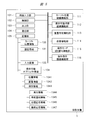
- FIG. 2 is an explanatory diagram showing an example of the configuration of the wearable information processing apparatus 2 according to the first embodiment.
- the wearable information processing apparatus 2 that is a wearable device includes a displacement detection unit 201, a control unit 202, an input unit 203, an output unit 204, a communication unit 205, and a storage unit 206.
- the wearable information processing apparatus 2 includes a displacement detection process execution instruction function unit 210, an inclination detection process execution instruction function unit 211, and a response result determination function unit 212.
- Each of these functional units is realized by the control unit 202 executing based on a program that is software, for example.
- each functional unit described above is realized by software, but each functional unit may be realized by hardware, part or all of them. Alternatively, hardware and software may be used in combination.
- the displacement detection unit 201 which is a displacement sensor, is a sensor that can detect the tilt and displacement of the wearable information processing apparatus 2, and is realized by using, for example, a 3D acceleration sensor that can detect acceleration or a 3D gyroscope that can detect angular velocity. Also good.
- the control unit 202 that constitutes the control information generation unit includes a CPU and a memory that control an input unit 203 and a communication unit 205, which will be described later, and these peripheral devices, and implements various functions by executing programs.
- the input unit 203 that is a contact unit inputs a timing for executing the detection process to the displacement detection unit 201.
- a timing for executing the detection process For example, it may be a button that inputs an execution timing by pressing, or a microphone that can recognize a specific instruction voice and input the execution timing.
- the output unit 204 serving as a vibration generating unit is a device for outputting prior notification information 1345, intermediate response information 1346, and final response information 1347 indicating the response to the instruction received from the communication unit 104 of the projection apparatus 1 and the success or failure of the process. It is.
- the output unit 204 is a speaker or the like when outputting by sound, such as an LED (Light Emitting Diode) when outputting by display, but here the output unit 204 assumes a vibrator or the like, The case where it outputs using the vibration of a vibrator is demonstrated.
- LED Light Emitting Diode
- the communication unit 205 serving as the first communication unit transmits the displacement information 221 and the tilt information 222 acquired by the displacement detection unit 201 to the communication unit 104 of the projection apparatus 1 and responds to instructions from the communication unit 104 of the projection apparatus 1.
- the communication module can also receive advance notification information 1345 indicating success or failure of processing, intermediate response information 1346, and final response information 1347.
- Bluetooth communication will be described as an example, but the communication method in the communication unit 205 is not limited to this.
- the storage unit 206 is a storage medium composed of a semiconductor memory or the like, and may be a fixed type or a removable type.
- the storage unit 206 stores displacement information 221, inclination information 222, operation response information 223, and operation mode information 224.
- the displacement information 221 is data indicating the displacement of the wearable information processing apparatus 2 that can be acquired by the displacement detection unit 201.
- the inclination information 222 is data indicating the inclination of the wearable information processing apparatus 2 that can be acquired by the displacement detection unit 201.
- the operation response information 223 indicates prior notification information 1345, intermediate response information 1346, and final response information 1347 received from the projection apparatus 1 via the communication unit 205.
- Whether the operation mode information 224 is a cursor operation mode for operating the cursor on the projection apparatus 1 or a gesture operation mode for operating the projection apparatus 1 is the current operation purpose of the wearable information processing apparatus 2 It is data representing. Data representing the cursor operation mode in the operation mode information 224 is the first control information, and data representing the gesture operation mode is the second control information.
- the authentication information 225 is a password, PIN information, or the like shared for the communication unit 205 to communicate with other devices.
- the displacement detection process execution instruction function unit 210 instructs the displacement detection unit 201 to execute a displacement detection process when an input is made to the input unit 203.
- the displacement detection process execution instruction function unit 210 may stop the displacement detection process of the displacement detection unit 201, or perform a process of acquiring detected displacement data from the displacement detection unit 201. You may stop. Alternatively, the process of storing the displacement information 221 in the storage unit 206 may be stopped.
- the tilt detection process execution instruction function unit 211 instructs the displacement detection unit 201 to execute a tilt detection process when an input is made to the input unit 203.
- the displacement detection process execution instruction function unit 210 may stop the inclination detection process of the displacement detection unit 201, or perform a process of acquiring detected inclination data from the displacement detection unit 201. You may stop. Or you may stop the process stored in the memory
- the response result determination function unit 212 analyzes the prior notification information 1345, the intermediate response information 1346, and the final response information 1347 received via the communication unit 104 of the projection apparatus 1, and determines the success or failure of the instructed process.
- the operation mode determination function unit 213 constituting the control information generation unit determines whether the current operation mode is the cursor operation mode or the gesture operation mode according to the data of the inclination information 222 stored in the storage unit 206. .
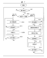
- FIG. 3 is a flowchart showing an example of processing by the wearable information processing apparatus 2 of FIG.
- FIG. 3 shows an example of processing by the wearable information processing apparatus 2 when operating the projection apparatus 1.
- the pairing process in the Bluetooth communication with the projection apparatus 1 is completed via the communication unit 205, and a state where communication is possible is set as a start state.
- the authentication information 225 is shared via the communication unit 205 to the communicable projection apparatus 1.
- control unit 202 determines whether or not there is an input to the input unit 203 (step S101).
- the input unit 203 is realized with buttons.
- the control unit 202 When the input is performed on the input unit 203, that is, when a button is pressed, the control unit 202 performs the inclination detection process execution instruction function unit 211 and the displacement detection process execution only during a predetermined time from the time the button is pressed or immediately after the button is pressed.
- the instruction function unit 210 is instructed to execute.
- the inclination detection processing execution instruction function unit 211 acquires the inclination data collected by the displacement detection unit 201 and stores it in the storage unit 206 as inclination information 222.
- the misrecognition of the operation mode can be reduced by capturing the inclination data collected by the displacement detection unit 201 only during a certain time from when the button is pressed or immediately after the button is pressed.
- the operation mode determination function unit 213 determines whether the current operation mode is the cursor operation mode or the gesture operation mode from the data of the inclination information 222 stored in the storage unit 206, and the determination result is stored in the storage unit
- the operation mode information 224 is stored in 206 (step S102).
- the cursor operation mode for pointing to the projection displayed on the remote projection apparatus 1 is determined.
- the displacement detection process execution instruction function unit 210 stores the displacement data collected by the displacement detection unit 201 in the storage unit 206 as displacement information 221, together with the operation mode information 224, via the communication unit 205. To the projection apparatus 1 (step S103).
- the control unit 202 determines whether a response from the projection apparatus 1 has been received via the communication unit 205 (step S104). As a result of the determination, when a response is received, the response is stored in the storage unit 206 as the operation response information 223, and the response is output via the output unit 204 based on the operation response information 223 (step S105). At this time, any of the prior notification information 1345, the intermediate response information 1346, and the final response information 1347 is included as a response.
- the response result determination function unit 212 may analyze the contents of the prior notification information 1345, the intermediate response information 1346, or the final response information 1347 and determine the success or failure of the instructed process. As a result of this determination, a predetermined output may be instructed to the output unit 204 according to success or failure, and the response result determination function unit 212 does not make a determination, but the advance notification information 1345, the intermediate response information 1346, the final You may control the output part 204 according to the data regarding the ringing time of the output part 204 which is a vibrator contained in the response information 1347, etc.
- step S106 it is determined whether or not input to the input unit 203 is continued without particularly outputting according to the response. If the input is continued as a result of the determination, the process returns to the process of step S103 and the transmission of the displacement information 221 and the inclination information 222 is continued.
- FIG. 4 is a flowchart showing an example of processing by the projection apparatus 1. As described above, the projection apparatus 1 is operated in response to an instruction from the wearable information processing apparatus 2.
- the projection apparatus 1 sets a start state in which a pairing process for connecting to the wearable information processing apparatus 2 via the communication unit 104 is completed.
- the authentication information 131 is shared via the communication unit 104 to the wearable information processing apparatus 2 that can communicate.
- control unit 102 determines whether the communication unit 104 has received the displacement information 221 and the tilt information 222 transmitted from the communication unit 205 of the wearable information processing apparatus 2 (step S201). If received, the process proceeds to step S202. On the other hand, if it has not been received, the process returns to step S201 to wait for reception.
- the operation mode is determined based on the received inclination information 222 (step S202). For example, when the received tilt information 222 indicates the horizontal direction as the wearable information processing apparatus 2, the control unit 102 controls the operation mode switching function unit 115 to switch the operation mode to the cursor operation mode. The process proceeds to S203.
- the control unit 102 controls the operation mode switching function unit 115 to change the operation mode to the gesture operation mode. The process proceeds to step S209.
- step S202 In the determination of the operation mode in the process of step S202, if the tilt information 222 indicates the horizontal direction as the wearable information processing apparatus 2, the displacement of the cursor is calculated based on the received displacement information 221 (step S203). ).
- the movement distance in each axis can be calculated by integrating these values.
- the calculation method is not limited to this.
- control unit 102 updates the cursor position information 130 by adding the above-described cursor movement distance to the current cursor position information 130 stored in the storage unit 105 (step S204).
- control unit 102 generates a cursor image based on the updated cursor position information 130, combines it with the input image information 133 input to the image input unit 101, and then outputs it via the output unit 103 ( Step S205).
- control unit 102 performs superimposition determination (step S206).
- the superimposition determination by the control unit 202 recognizes the cursor position as described below, and determines whether or not the image information 1342 of the operable object and the cursor position overlap.
- the object is, for example, a menu or button on the screen to which an operation is assigned.
- the cursor position recognition function unit 111 reads the current cursor position information 130 stored in the storage unit 105. Subsequently, the superimposition determination function unit 113 determines whether or not the current cursor position information 130 is included in the set of position information 1341 constituting the operable object in the video displayed via the output unit 103. Determine. Thus, the superimposition determination is completed.
- the operable state recognition function unit 112 determines whether or not the operable object on which the cursor is superimposed is operable (step S207).
- the process returns to the process of step S201.
- the response function unit 114 transmits the content of the advance notification information 1345 or the intermediate response information 1346 via the communication unit 104. 2 (step S208), the process returns to step S201.
- the operation instruction recognition function unit 116 When switching to the gesture operation mode in the process of step S202, the operation instruction recognition function unit 116 performs a process of recognizing the gesture operation by comparing the gesture pattern information 132 stored in the storage unit 105 with the displacement information 221. Is executed (step S209).
- the process returns to step S201 and continues to receive the displacement information 221 via the communication unit 104 and continues to recognize the gesture operation.
- the operation mode switching function unit 115 may switch the operation mode to the cursor operation mode.
- the response function unit 114 may transmit a recognition failure response to the wearable information processing apparatus 2 via the communication unit 104.
- the response function unit 114 transmits a response of recognition success to the wearable information processing apparatus 2 via the communication unit 104 (step S210).
- control unit 102 executes the operation described in the execution information 1344 associated with the recognized gesture operation (step S211). Thereafter, it is determined whether or not the same operable object can be continuously operated (step S212).
- the response function unit 114 transmits the intermediate response information 1346 to the wearable information processing apparatus 2 (step S208).
- the response function unit 114 sends the final response information 1347, which is the final result of a series of operations, via the communication unit 104 to the wearable information. After transmitting to the processing apparatus 2 (step S213), the process returns to the process of step S201 and continues to receive the displacement information.
- This drag-and-drop operation process includes a first process in which the user selects an object, a second process in which the position of the object is moved and changed, and a third process in which the object is finally released to determine the position. It consists of three stages of processing.
- the projection apparatus 1 receives the displacement of the wearable information processing apparatus 2 operating in the cursor mode (step S201), and determines the operation mode from the tilt information of the wearable information processing apparatus 2 (step S202). At this time, if the cursor operation mode is still determined, the cursor position is calculated from the displacement information (step S203).
- step S204 the cursor position is updated (step S204), and the cursor image and the projected image are combined and output (step S205). Then, it is determined whether or not the cursor is superimposed on the object with the position (step S206).
- step S207 it is determined whether or not the object can be operated. If the object can be operated, drag and drop can be performed on the wearable information processing apparatus 2. Notification to that effect is made (step S208). In this case, prior notification information 1345 such as 1-second vibration output from the output unit 204 is transmitted to the wearable information processing apparatus 2.
- the user recognizes that the drag-and-drop is possible by the vibration of the wearable information processing apparatus 2, and switches to the gesture operation mode by changing the inclination of the wearable information processing apparatus 2. If not switched, the cursor operation mode is continued and the cursor position is continuously updated.
- the projection apparatus 1 receives the displacement information from the wearable information processing apparatus 2 (step S201), and determines the operation mode based on the content of the tilt information (step S202). Then, it is determined whether or not the gesture operation indicating the selection of the object can be recognized from the locus or history of the displacement information of the wearable information processing device 2 (step S209).
- the gesture operation in this case is, for example, a pulling gesture.
- step S210 If the gesture indicating selection has not been recognized, the process returns to step S201 to continuously receive the displacement. If the gesture recognition indicating selection is successful, a response indicating success is transmitted to the wearable information processing apparatus 2 (step S210).
- step S211 processing related to the recognized gesture operation is executed (step S211), and it is determined whether there is a continuation operation in the drag and drop operation (step S212).
- step S212 the control unit 102 makes a determination based on the information in the intermediate response information 1346.
- advance notification information 1345 indicating that it is time to move the object is transmitted (step S208). Based on this prior notification information 1345, the user is notified that it is time to allow the wearable information processing apparatus 2 to vibrate and move the object.
- the user receives the notification and changes the inclination of the wearable information processing apparatus 2 to switch to the cursor operation mode. Thereafter, the user moves the wearable information processing apparatus 2 and transmits the displacement of the wearable information processing apparatus 2 in order to drag the object.
- the projection device 1 receives the displacement of the wearable information processing device 2 from the wearable information processing device 2 (step S201), and determines the operation mode from the tilt information of the wearable information processing device 2 (step S202).
- step S203 the position of the cursor is updated (steps S203 and S204), a composite image relating to the movement of the object is created (step S205), and a superimposition determination is performed (step S206).
- step S207 when it is determined that the cursor is superimposed at a position where the subsequent object drop operation can be performed and the drop operation is possible (step S207), prior notification information 1345 that the drop can be performed. Is sent to the wearable information processing apparatus 2 (step S208). Subsequently, a third process is performed.
- the user Upon receiving the notification, the user changes the inclination of the wearable information processing apparatus 2 and switches to the gesture operation mode. Subsequently, a gesture operation for dropping the object is performed, and the displacement of the wearable information processing apparatus 2 is transmitted.
- the gesture operation in this case is, for example, a movement that protrudes forward.
- the projection apparatus 1 receives the displacement and inclination information, and recognizes the drop gesture operation from the displacement information when determining that the operation mode is the gesture operation mode (steps S201 to S210).
- the gesture operation may be a cancel gesture operation.
- step S210 If the recognition is successful, the recognition success is notified (step S210), and the projection apparatus 1 performs a drop process (step S211).
- step S212 since there is no continuation operation in the drag-and-drop operation (step S212), final response information 1347 is transmitted to the wearable information processing apparatus 2 (step S213). As described above, all the drag-and-drop processes are completed.
- the cursor operation mode and the gesture operation mode can be quickly switched on the projection apparatus 1 side based on the tilt information and input of the wearable information processing apparatus 2. Furthermore, based on the displacement information and the tilt information of the wearable information processing device 2, both the instruction operation on the projection image and the output control operation of the projection image by the cursor in the projection device 1 can be executed.
- FIG. 5 is an explanatory diagram showing an example of the configuration of the projection apparatus 1 according to the second embodiment.
- the projector 1 of FIG. 5 is different from the projector 1 of FIG. 1 of the first embodiment in that the gesture pattern information 132 included in the projector 1 of FIG. 1 is not provided.
- Other configurations are the same as those of the first embodiment shown in FIG. ⁇ Configuration example of wearable information processing device>
- FIG. 6 is an explanatory diagram showing an example of the configuration of the wearable information processing apparatus 2 according to the second embodiment.
- the wearable information processing apparatus 2 of FIG. 6 has an operation instruction recognition function unit 214, an operation instruction transmission function part 215, and gesture pattern information in addition to the configuration of the wearable information processing apparatus 2 of FIG. 2 of the first embodiment. 226 is newly provided.
- the operation instruction recognition function unit 214 and the operation instruction transmission function unit 215 are realized by the control unit 202 executing based on a program that is software, for example.
- FIG. 7 is a flowchart showing an example of processing by the wearable information processing apparatus 2 of FIG.
- FIG. 7 shows a processing example in the wearable information processing apparatus 2 that operates the projection apparatus 1.
- step S301 the process in step S301, and the processes in steps S303 to S306 are the same as the start state in FIG. 3 in the first embodiment, the process in step S101, and the processes in steps S103 to S106. Since there is, explanation is omitted. Therefore, here, the processing of step S302 and the processing of S307 to S312 which are differences from FIG. 3 will be described.
- step S301 when there is a pressing input to the input unit 203, the operation mode determination function unit 213 determines the operation mode in the current wearable information processing apparatus 2 (step S302), and displays the determination result. Stored as operation mode information 224.
- step S303 when it is determined from the tilt data or the like that the operation mode is the cursor operation mode, the process proceeds to step S303 as in the process of step S102 of FIG.
- the operation instruction recognition function unit 214 of the wearable information processing apparatus 2 determines the gesture pattern information based on the displacement information 221 and the inclination information 222 acquired from the displacement detection unit 201. Verification with H.226 is performed (step S307).
- step S308 if a matching gesture operation can be identified, the process proceeds to step S308. On the other hand, if it cannot be specified, the process returns to step S307. At this time, if the operation fails for a predetermined number of times or if the gesture operation cannot be recognized for the predetermined time or more, the operation mode determination function unit 213 may switch the operation mode to the cursor operation mode.
- step S307 if a matching gesture operation can be identified, information indicating that the gesture operation has been successfully recognized is output via the output unit 204 (step S308). At this time, it may be output based on the operation response information 223 preset in the storage unit 206. For example, when the output content for notifying that the recognition is successful is defined to continue the weak vibration for 0.5 seconds, the control unit 202 controls the output unit 204 according to this.
- the operation instruction transmission function unit 215 transmits the operation instruction to the projection apparatus 1 via the communication unit 205 so as to execute the operation associated with the matched gesture operation (step S309). ).
- control unit 202 determines whether or not there is a response to the operation instruction from the communication unit 205 of the projection apparatus 1 (step S310). If there is a response, the response content is output via the output unit 204 (step S311).
- step S312 it is determined whether or not the input to the input unit 203 is continued. If the input continues, the process returns to step S307 to continue the recognition process for the next gesture operation. On the other hand, if the input is not continued, the process returns to step S301 and waits for an input to the input unit 203.
- FIG. 8 is a flowchart showing an example of processing by the projection apparatus 1 of FIG.
- FIG. 8 shows a processing example of the projection apparatus 1 operated in response to an instruction from the wearable information processing apparatus 2.
- the start state in FIG. 8 the processing in steps S403 to 408, and the processing in steps S411 to S413 are the same as the start state in FIG. 4 in the first embodiment, the processing in steps S203 to S208, and the processing in steps S211 to S213. Since it is the same as the process, the description is omitted. Therefore, here, the processing in step S401, the processing in steps S402, and S410, which are differences from FIG. 4, will be described. In FIG. 8, there is no processing in step S409.
- the projection apparatus 1 determines whether or not displacement information has been received from the wearable information processing apparatus 2 via the communication unit 104 (step S401). If the displacement information is received as a result of the determination, the operation mode switching function unit 115 updates the operation mode to the cursor operation mode and executes the process of step S403. On the other hand, when displacement information is not received, the control part 102 determines whether the operation instruction is received from the communication part 205 of the mounting
- the operation instruction recognition function unit 116 of the projection apparatus 1 can recognize the operation instruction associated with the gesture operation recognized on the wearable information processing apparatus 2 side. Then, a response of recognition success is transmitted to the wearable information processing apparatus 2 via the communication unit 104 (step S410). Whether or not this response has been received is determined by the wearable information processing apparatus 2 in the process of step S310 in FIG.
- step S402 if an operation instruction has been received, the process returns to step S401 and waits for reception of displacement information or an operation instruction.
- the cursor operation mode and the gesture operation mode can be quickly switched on the wearable information processing device 2 side based on the tilt information and input of the wearable information processing device 2. Furthermore, based on the displacement information and operation instructions from the wearable information processing apparatus 2, both the instruction operation on the projection image and the output control operation of the projection image by the cursor in the projection apparatus 1 can be executed.
- the operation efficiency of the projection apparatus 1 can be improved.
- the wearable information processing apparatus 2 can reduce the amount of data transmitted to the projection apparatus 1 by transmitting only an operation instruction for executing an operation associated with the recognized gesture operation to the projection apparatus 1. it can.
- the transmission time can be shortened and the power required for transmission can be reduced, the power consumption of the wearable information processing apparatus 2 can be reduced.
- a part of the configuration of one embodiment can be replaced with the configuration of another embodiment, and the configuration of another embodiment can be added to the configuration of one embodiment. .
Landscapes
- Engineering & Computer Science (AREA)
- General Engineering & Computer Science (AREA)
- Theoretical Computer Science (AREA)
- Human Computer Interaction (AREA)
- Physics & Mathematics (AREA)
- General Physics & Mathematics (AREA)
- User Interface Of Digital Computer (AREA)
Abstract
L'objectif de la présente invention est de commander de manière efficace une sortie vidéo par des opérations gestuelles en plus d'opérations de mouvement de curseur. L'invention concerne un dispositif de traitement d'informations portable sur soi 2, dans lequel une unité de détection de déplacement 201 détecte l'inclinaison du dispositif de traitement d'informations portable sur soi 2 et le déplacement du dispositif de traitement d'informations portable sur soi 2. Une unité d'entrée 203 détecte un contact d'un objet. Une unité de commande 202 génère des informations de commande qui sont transmises par l'intermédiaire d'une première unité de communication à un dispositif d'affichage vidéo. L'unité de commande 202 génère les informations de commande en fonction de l'inclinaison du dispositif de traitement d'informations portable sur soi 2 que l'unité de détection de déplacement 201 a détecté dans un intervalle dans lequel la détection de contact est faite par l'unité d'entrée 203 ou un intervalle après une détection de contact par l'unité de détection de contact, et émet les informations de commande générées et le déplacement détecté du dispositif de traitement d'informations portable sur soi 2 à partir de l'unité de communication 205. Les informations de commande que l'unité de commande 202 génère sont des premières informations de commande qui changent la position d'un curseur ou d'un pointeur qui est affichée dans une vidéo émise du dispositif d'affichage vidéo, ou des secondes informations de commande qui sont différentes des premières informations de commande, et commandent un dispositif de projection.
Priority Applications (1)
| Application Number | Priority Date | Filing Date | Title |
|---|---|---|---|
| PCT/JP2015/069498 WO2017006426A1 (fr) | 2015-07-07 | 2015-07-07 | Système d'affichage, dispositif portable sur soi, et dispositif d'affichage vidéo |
Applications Claiming Priority (1)
| Application Number | Priority Date | Filing Date | Title |
|---|---|---|---|
| PCT/JP2015/069498 WO2017006426A1 (fr) | 2015-07-07 | 2015-07-07 | Système d'affichage, dispositif portable sur soi, et dispositif d'affichage vidéo |
Publications (1)
| Publication Number | Publication Date |
|---|---|
| WO2017006426A1 true WO2017006426A1 (fr) | 2017-01-12 |
Family
ID=57684904
Family Applications (1)
| Application Number | Title | Priority Date | Filing Date |
|---|---|---|---|
| PCT/JP2015/069498 WO2017006426A1 (fr) | 2015-07-07 | 2015-07-07 | Système d'affichage, dispositif portable sur soi, et dispositif d'affichage vidéo |
Country Status (1)
| Country | Link |
|---|---|
| WO (1) | WO2017006426A1 (fr) |
Citations (4)
| Publication number | Priority date | Publication date | Assignee | Title |
|---|---|---|---|---|
| JP2000276534A (ja) * | 1999-11-10 | 2000-10-06 | Tatsuo Taguchi | 製品付帯情報の表示方法、その表示装置及びその表示記録媒体 |
| JP2014149856A (ja) * | 2007-07-27 | 2014-08-21 | Qualcomm Inc | 高度なカメラをベースとした入力 |
| JP2015121979A (ja) * | 2013-12-24 | 2015-07-02 | 株式会社東芝 | 装着型情報入力装置、情報入力システム、及び情報入力方法 |
| WO2015098190A1 (fr) * | 2013-12-27 | 2015-07-02 | ソニー株式会社 | Dispositif de commande, procédé de commande, et programme informatique |
-
2015
- 2015-07-07 WO PCT/JP2015/069498 patent/WO2017006426A1/fr active Application Filing
Patent Citations (4)
| Publication number | Priority date | Publication date | Assignee | Title |
|---|---|---|---|---|
| JP2000276534A (ja) * | 1999-11-10 | 2000-10-06 | Tatsuo Taguchi | 製品付帯情報の表示方法、その表示装置及びその表示記録媒体 |
| JP2014149856A (ja) * | 2007-07-27 | 2014-08-21 | Qualcomm Inc | 高度なカメラをベースとした入力 |
| JP2015121979A (ja) * | 2013-12-24 | 2015-07-02 | 株式会社東芝 | 装着型情報入力装置、情報入力システム、及び情報入力方法 |
| WO2015098190A1 (fr) * | 2013-12-27 | 2015-07-02 | ソニー株式会社 | Dispositif de commande, procédé de commande, et programme informatique |
Similar Documents
| Publication | Publication Date | Title |
|---|---|---|
| US9586147B2 (en) | Coordinating device interaction to enhance user experience | |
| KR20150023293A (ko) | Asr 및 ht 입력을 갖는 보조 디스플레이로서 헤드셋 컴퓨터(hsc) | |
| US20150109437A1 (en) | Method for controlling surveillance camera and system thereof | |
| JP6357023B2 (ja) | 情報処理プログラム、情報処理装置、情報処理装置の制御方法および情報処理システム | |
| EP3631606B1 (fr) | Dispositif d'affichage, dispositif terminal utilisateur, système d'affichage le comprenant et procédé de comande associé | |
| US20150138109A1 (en) | Input device, control method and portable terminal device | |
| WO2014207828A1 (fr) | Dispositif et programme de traitement d'informations | |
| KR101305944B1 (ko) | 랩어라운드 영상을 이용한 로봇 원격 제어를 위한 방법 및 이를 위한 장치 | |
| EP3299930A1 (fr) | Interaction de réalité virtuelle | |
| US10437415B2 (en) | System, method, and device for controlling a display | |
| US11837198B2 (en) | Head mounted display and setting method | |
| KR102617252B1 (ko) | 전자 장치 및 그 파노라마 촬영 모드 자동 전환 방법 | |
| WO2017006426A1 (fr) | Système d'affichage, dispositif portable sur soi, et dispositif d'affichage vidéo | |
| JP7252398B2 (ja) | 仮想オブジェクト操作方法およびヘッドマウントディスプレイ | |
| KR102462204B1 (ko) | 진동을 제공하기 위한 장치 및 방법 | |
| KR20180043627A (ko) | 디스플레이 장치 및 디스플레이 장치를 제어하는 방법 | |
| US11275547B2 (en) | Display system, display method, and program | |
| KR20110032224A (ko) | 제스처에 의한 사용자 인터페이스 제공 시스템 및 방법과 이를 위한 제스처신호 발생장치 및 단말기 | |
| JP5830899B2 (ja) | 投影システム、投影装置、投影方法及びプログラム | |
| JP6779715B2 (ja) | 情報処理システム | |
| KR101305947B1 (ko) | 랩어라운드 영상을 이용한 로봇 원격 제어를 위한 방법 및 이를 위한 장치 | |
| JP2007226397A (ja) | ポインティング装置、ポインティング方法、ポインティングプログラムおよびポインティングプログラムを記録した記録媒体 | |
| JP2007279869A (ja) | プロジェクター、プロジェクター用リモコンおよびポインターシステム | |
| JP6484914B2 (ja) | 情報処理機器および操作システム | |
| KR20180108100A (ko) | 헤드 마운티드 디스플레이를 포함하는 시스템 및 그 제어 방법 |
Legal Events
| Date | Code | Title | Description |
|---|---|---|---|
| 121 | Ep: the epo has been informed by wipo that ep was designated in this application |
Ref document number: 15897689 Country of ref document: EP Kind code of ref document: A1 |
|
| NENP | Non-entry into the national phase |
Ref country code: DE |
|
| NENP | Non-entry into the national phase |
Ref country code: JP |
|
| 122 | Ep: pct application non-entry in european phase |
Ref document number: 15897689 Country of ref document: EP Kind code of ref document: A1 |