WO2017006426A1 - Display system, wearable device, and video display device - Google Patents
Display system, wearable device, and video display device Download PDFInfo
- Publication number
- WO2017006426A1 WO2017006426A1 PCT/JP2015/069498 JP2015069498W WO2017006426A1 WO 2017006426 A1 WO2017006426 A1 WO 2017006426A1 JP 2015069498 W JP2015069498 W JP 2015069498W WO 2017006426 A1 WO2017006426 A1 WO 2017006426A1
- Authority
- WO
- WIPO (PCT)
- Prior art keywords
- control information
- wearable device
- video
- unit
- display device
- Prior art date
Links
Images


Classifications
-
- G—PHYSICS
- G06—COMPUTING; CALCULATING OR COUNTING
- G06F—ELECTRIC DIGITAL DATA PROCESSING
- G06F3/00—Input arrangements for transferring data to be processed into a form capable of being handled by the computer; Output arrangements for transferring data from processing unit to output unit, e.g. interface arrangements
- G06F3/01—Input arrangements or combined input and output arrangements for interaction between user and computer
- G06F3/03—Arrangements for converting the position or the displacement of a member into a coded form
- G06F3/033—Pointing devices displaced or positioned by the user, e.g. mice, trackballs, pens or joysticks; Accessories therefor
- G06F3/0346—Pointing devices displaced or positioned by the user, e.g. mice, trackballs, pens or joysticks; Accessories therefor with detection of the device orientation or free movement in a 3D space, e.g. 3D mice, 6-DOF [six degrees of freedom] pointers using gyroscopes, accelerometers or tilt-sensors
Definitions
- the present invention relates to a display system, a wearable device, and a video display device, and more particularly to a technique effective for improving the operability of an image display device.
- Projectors are widely used as projection equipment for projecting monitor images on screens.
- As an indication technique of an instruction destination in a projector for example, a technique using a laser type pointer independent of a projector or a technique using a cursor image is widely used.
- the cursor image is output by superimposing the cursor image on the video by connecting an information device such as a personal computer or a smartphone storing the video to the projector.
- the pointer when a pointer is used, the pointer must be held in either the left or right hand, and the hand is blocked. Similarly, when moving the cursor on the cursor screen, the keys of the information device have to be operated, and the hands are blocked.
- Patent Document 1 recognizes a gesture operation of a human hand and updates the display position of the cursor. However, since there is no description other than the operation of moving the cursor, it cannot be expanded to other operations utilizing the projection function.
- the information device or the like when displaying the next page, the information device or the like must be operated, and the presenter's hand is blocked during the operation.
- the presenter's hand is blocked during the operation.
- the user at the time of presentation, as described above, there are many cases where the user possesses materials, tablets, and the like, and it is considered that the operation of the information device becomes difficult.
- An object of the present invention is to provide a technique capable of efficiently controlling an output video by a gesture operation in addition to a cursor movement operation.
- a typical display system includes a video display device and a wearable device capable of operating the video display device by communicating with the video display device.
- the wearable device includes a first communication unit, a displacement sensor, a contact detection unit, and a control information generation unit.
- the first communication unit communicates with the video display device.
- the displacement sensor detects the inclination of the wearable device and the displacement of the wearable device.
- the contact detection unit detects contact of an object.
- the control information generation unit generates control information to be transmitted to the video display device via the first communication unit.
- the video display device includes a video output unit, a second communication unit, and a video generation unit.
- the video output unit displays or projects the video.
- the second communication unit communicates with the wearable device.
- the video generation unit changes the content of the output video from the video output unit in accordance with control information received from the wearable device via the second communication unit.
- the wearable device control information generation unit controls the wearable device detected by the displacement sensor during a period in which contact detection is performed by the contact detection unit or a period after contact detection is performed by the contact detection unit. Information is generated, and the generated control information and the displacement of the wearable device detected by the displacement sensor are output from the first communication unit.
- the control information generated by the control information generation unit includes the first control information or the second control information, and the first control information changes the position of the cursor or pointer displayed in the output video of the video display device.
- the second control information is control information for controlling a video display device different from the first control information.
- the wearable device includes a vibration generating unit that vibrates the wearable device.
- the video display device indicates that the cursor or pointer has overlapped with the position from the second communication unit.
- the first notification information is transmitted to the communication unit of the wearable device.
- the vibration generating unit generates vibration when the communication unit of the wearable device receives the first notification information.
- the operability of the video display device can be improved.
- FIG. 10 is an explanatory diagram illustrating an example of a configuration of a projection device according to a second embodiment.
- FIG. 10 is an explanatory diagram illustrating an example of a configuration of a wearable information processing apparatus according to a second embodiment. It is a flowchart which shows an example of the process by the mounting
- the constituent elements are not necessarily indispensable unless otherwise specified and apparently essential in principle. Needless to say.
- the display system includes a projection device 1 shown in FIG. 1 and a wearable information processing device 2 shown in FIG. Further, the wearable information processing apparatus 2 can operate the projection apparatus 1 by communicating with the projection apparatus 1.
- FIG. 1 is an explanatory diagram showing an example of the configuration of the projection apparatus 1 according to the first embodiment.
- the projection device 1 that is a video display device includes an image input unit 101, a control unit 102, an output unit 103, a communication unit 104, and a storage unit 105.
- the projection apparatus 1 also includes a cursor position recognition function unit 111, an operable state recognition function unit 112, a superimposition determination function unit 113, a response function unit 114, an operation mode switching function unit 115, and an operation instruction recognition function unit 116.
- a cursor position recognition function unit 111 an operable state recognition function unit 112
- a superimposition determination function unit 113 a response function unit 114
- an operation mode switching function unit 115 an operation instruction recognition function unit 116.
- Each of these functional units is realized when the control unit 102 described later executes based on a program that is software, for example.
- each of the functional units described above is realized by software.
- each functional unit may be realized by hardware, part or all of them.
- hardware and software may be used in combination.
- the image input unit 101 serving as a video generation unit is a connection interface that can input video or audio signals from the outside or the inside.
- the image input unit 101 may be an RGB input terminal, an HDMI (High Definition Multimedia Interface) terminal, a USB (Universal Serial Bus) terminal, an SD card slot, or the like.
- RGB input terminal is a terminal that can input video.
- the HDMI terminal is a terminal corresponding to an interface standard such as digital video or audio, and inputs a moving image to an externally connected high-vision monitor or the like.
- the USB terminal is a connection terminal with an external device, and inputs a moving image to an external memory, for example.
- the SD card slot is a slot into which an SD memory card is inserted.
- the control unit 102 serving as a video generation unit includes a CPU (Central Processing Unit) that controls a communication unit 104 and functional units described later, a memory, peripheral devices, and the like. Realize the functions.
- CPU Central Processing Unit
- the output unit 103 serving as a video output unit has a function of displaying and outputting a video signal and an audio signal input via the image input unit 101.
- the output unit 103 is, for example, a projector that projects video or a direct-view display that outputs video and audio.
- the communication unit 104 is a communication module that receives an operation instruction of the projection apparatus 1 from another device and transmits a response thereof, and corresponds to, for example, Bluetooth communication.
- the communication between the projection apparatus 1 and the wearable information processing apparatus 2 shown in FIG. 2 is performed by Bluetooth communication, but the communication method is not limited to this, and other communication methods are used. May be.
- the storage unit 105 is an information storage medium and includes a semiconductor memory, an HDD (Hard Disc Drive), or the like.
- the storage unit 105 may be a fixed type that cannot be removed from the projection apparatus 1 or a removable type that can be removed.
- the storage unit 105 stores cursor position information 130, authentication information 131, gesture pattern information 132, input image information 133, and operable object information 134, which will be described later.
- the cursor position recognition function unit 111 reads the current cursor position information 130 stored in the storage unit 105.
- the operable state recognition function unit 112 determines whether the object on which the cursor is superimposed is operable. For example, operation information 1343 related to the object on which the cursor is superimposed is read from the storage unit 105, and when there is operation information 1343, it is determined that the operation is possible.
- the video generation unit superimposition determination function unit 113 determines whether or not the current cursor position information 130 is included in the set of position information 1341 constituting the operable object in the video displayed via the output unit 103. Determine.
- the response function unit 114 transmits advance notification information 1345, intermediate response information 1346, and final response information 1347 regarding the operation via the communication unit 104.
- the operation mode switching function unit 115 receives an instruction from the control unit 102 and switches the operation mode to the cursor operation mode or the gesture operation mode.
- the cursor operation mode is mainly intended to simply move the cursor image output via the output unit 103 or to select an operable object described later.
- the gesture operation mode includes switching of the input image information 133 output via the output unit 103, advance / retreat, and enlargement / reduction, and processing associated with an operable object image to be combined with the input image information 133.
- the main purpose is to instruct execution using gestures.
- the operation instruction recognition function unit 116 compares the gesture pattern information 132 stored in the storage unit 105 with the displacement information 221 and recognizes the gesture operation.
- the cursor position information 130 is a coordinate value representing the current position of the cursor projected and displayed via the output unit 103.
- the authentication information 131 is shared data for enabling communication between the projection apparatus 1 and the wearable information processing apparatus 2.
- the authentication information 131 is a password or PIN (Personal Identification ⁇ ⁇ Number) that can be input by the projection apparatus 1 or the wearable information processing apparatus 2. ) Indicates a number.
- the gesture pattern information 132 serving as operation pattern information is a set of gesture operations that can be recognized by an operation instruction recognition function unit 116 described later. For example, when a displacement in the right direction from the initial position can be detected, a function for controlling the projection apparatus 1 is assigned to each gesture operation, such as performing an operation to advance the projection image.
- the input image information 133 is a video or image input via the image input unit 101. This is an image that is a basis for generating a projection image that is output through the output unit 103 by superimposing a cursor image or the like.
- the operable object information 134 includes position information 1341 of the operable object, image information 1342 of the operable object, and operation information 1343 of the operable object, and a plurality of the operable object information 134 may be provided depending on the number of operable objects. it can.
- the position information 1341 of the manipulable object is a coordinate value indicating an area to which a specific operation execution instruction is assigned on the image projected via the output unit 103.
- this area is a polygon, it may be expressed as a set of coordinate values of points surrounding this area.
- the image information 1342 of the manipulable object is an image that visually indicates an area to which a specific operation execution instruction is assigned.
- the image input unit 101 may be superimposed on the video input and projected via the output unit 103, or the image information 1342 alone may be projected via the output unit 103.
- the operation information 1343 of the operable object includes execution information 1344, advance notification information 1345, intermediate response information 1346, and final response information 1347.
- the execution information 1344 is information representing processing to be executed on the control unit 102.
- the execution information 1344 can be assigned to power on / off, projection resumption stop, projection screen switching or advance / retreat, enlargement / reduction, volume change, etc.
- the prior notification information 1345 serving as the first and second notification information is data that is notified in advance to the wearable information processing apparatus 2 via the communication unit 104 when the operable object enters an operable standby state.
- data such as 5 seconds is specified for the prior notification information 1345 of an operable object that is intermittently vibrated at intervals of 1 second and the total time of the prior notification is 5 seconds.
- the intermediate response information 1346 indicates at least one of reception of an operation instruction when an operation execution instruction is given to an operable object, and whether or not the operation instruction is successfully executed when the operation continues thereafter. Data sent back to the wearable information processing apparatus 2 via the network.
- the specified content is not limited to this, and when there are a plurality of intermediate states, a plurality of specified states may be specified.
- the final response information 1347 is returned to the wearable information processing apparatus 2 via the communication unit 104 regarding the success or failure of the operation instruction when the operation is completed by this instruction when an operation execution instruction is given to the operable object.
- Data For example, the same kind of data as the intermediate response information 1346 described above may be stored, and the same data as the intermediate response information 1346 may be stored.
- FIG. 2 is an explanatory diagram showing an example of the configuration of the wearable information processing apparatus 2 according to the first embodiment.
- the wearable information processing apparatus 2 that is a wearable device includes a displacement detection unit 201, a control unit 202, an input unit 203, an output unit 204, a communication unit 205, and a storage unit 206.
- the wearable information processing apparatus 2 includes a displacement detection process execution instruction function unit 210, an inclination detection process execution instruction function unit 211, and a response result determination function unit 212.
- Each of these functional units is realized by the control unit 202 executing based on a program that is software, for example.
- each functional unit described above is realized by software, but each functional unit may be realized by hardware, part or all of them. Alternatively, hardware and software may be used in combination.
- the displacement detection unit 201 which is a displacement sensor, is a sensor that can detect the tilt and displacement of the wearable information processing apparatus 2, and is realized by using, for example, a 3D acceleration sensor that can detect acceleration or a 3D gyroscope that can detect angular velocity. Also good.
- the control unit 202 that constitutes the control information generation unit includes a CPU and a memory that control an input unit 203 and a communication unit 205, which will be described later, and these peripheral devices, and implements various functions by executing programs.
- the input unit 203 that is a contact unit inputs a timing for executing the detection process to the displacement detection unit 201.
- a timing for executing the detection process For example, it may be a button that inputs an execution timing by pressing, or a microphone that can recognize a specific instruction voice and input the execution timing.
- the output unit 204 serving as a vibration generating unit is a device for outputting prior notification information 1345, intermediate response information 1346, and final response information 1347 indicating the response to the instruction received from the communication unit 104 of the projection apparatus 1 and the success or failure of the process. It is.
- the output unit 204 is a speaker or the like when outputting by sound, such as an LED (Light Emitting Diode) when outputting by display, but here the output unit 204 assumes a vibrator or the like, The case where it outputs using the vibration of a vibrator is demonstrated.
- LED Light Emitting Diode
- the communication unit 205 serving as the first communication unit transmits the displacement information 221 and the tilt information 222 acquired by the displacement detection unit 201 to the communication unit 104 of the projection apparatus 1 and responds to instructions from the communication unit 104 of the projection apparatus 1.
- the communication module can also receive advance notification information 1345 indicating success or failure of processing, intermediate response information 1346, and final response information 1347.
- Bluetooth communication will be described as an example, but the communication method in the communication unit 205 is not limited to this.
- the storage unit 206 is a storage medium composed of a semiconductor memory or the like, and may be a fixed type or a removable type.
- the storage unit 206 stores displacement information 221, inclination information 222, operation response information 223, and operation mode information 224.
- the displacement information 221 is data indicating the displacement of the wearable information processing apparatus 2 that can be acquired by the displacement detection unit 201.
- the inclination information 222 is data indicating the inclination of the wearable information processing apparatus 2 that can be acquired by the displacement detection unit 201.
- the operation response information 223 indicates prior notification information 1345, intermediate response information 1346, and final response information 1347 received from the projection apparatus 1 via the communication unit 205.
- Whether the operation mode information 224 is a cursor operation mode for operating the cursor on the projection apparatus 1 or a gesture operation mode for operating the projection apparatus 1 is the current operation purpose of the wearable information processing apparatus 2 It is data representing. Data representing the cursor operation mode in the operation mode information 224 is the first control information, and data representing the gesture operation mode is the second control information.
- the authentication information 225 is a password, PIN information, or the like shared for the communication unit 205 to communicate with other devices.
- the displacement detection process execution instruction function unit 210 instructs the displacement detection unit 201 to execute a displacement detection process when an input is made to the input unit 203.
- the displacement detection process execution instruction function unit 210 may stop the displacement detection process of the displacement detection unit 201, or perform a process of acquiring detected displacement data from the displacement detection unit 201. You may stop. Alternatively, the process of storing the displacement information 221 in the storage unit 206 may be stopped.
- the tilt detection process execution instruction function unit 211 instructs the displacement detection unit 201 to execute a tilt detection process when an input is made to the input unit 203.
- the displacement detection process execution instruction function unit 210 may stop the inclination detection process of the displacement detection unit 201, or perform a process of acquiring detected inclination data from the displacement detection unit 201. You may stop. Or you may stop the process stored in the memory
- the response result determination function unit 212 analyzes the prior notification information 1345, the intermediate response information 1346, and the final response information 1347 received via the communication unit 104 of the projection apparatus 1, and determines the success or failure of the instructed process.
- the operation mode determination function unit 213 constituting the control information generation unit determines whether the current operation mode is the cursor operation mode or the gesture operation mode according to the data of the inclination information 222 stored in the storage unit 206. .
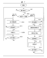
- FIG. 3 is a flowchart showing an example of processing by the wearable information processing apparatus 2 of FIG.
- FIG. 3 shows an example of processing by the wearable information processing apparatus 2 when operating the projection apparatus 1.
- the pairing process in the Bluetooth communication with the projection apparatus 1 is completed via the communication unit 205, and a state where communication is possible is set as a start state.
- the authentication information 225 is shared via the communication unit 205 to the communicable projection apparatus 1.
- control unit 202 determines whether or not there is an input to the input unit 203 (step S101).
- the input unit 203 is realized with buttons.
- the control unit 202 When the input is performed on the input unit 203, that is, when a button is pressed, the control unit 202 performs the inclination detection process execution instruction function unit 211 and the displacement detection process execution only during a predetermined time from the time the button is pressed or immediately after the button is pressed.
- the instruction function unit 210 is instructed to execute.
- the inclination detection processing execution instruction function unit 211 acquires the inclination data collected by the displacement detection unit 201 and stores it in the storage unit 206 as inclination information 222.
- the misrecognition of the operation mode can be reduced by capturing the inclination data collected by the displacement detection unit 201 only during a certain time from when the button is pressed or immediately after the button is pressed.
- the operation mode determination function unit 213 determines whether the current operation mode is the cursor operation mode or the gesture operation mode from the data of the inclination information 222 stored in the storage unit 206, and the determination result is stored in the storage unit
- the operation mode information 224 is stored in 206 (step S102).
- the cursor operation mode for pointing to the projection displayed on the remote projection apparatus 1 is determined.
- the displacement detection process execution instruction function unit 210 stores the displacement data collected by the displacement detection unit 201 in the storage unit 206 as displacement information 221, together with the operation mode information 224, via the communication unit 205. To the projection apparatus 1 (step S103).
- the control unit 202 determines whether a response from the projection apparatus 1 has been received via the communication unit 205 (step S104). As a result of the determination, when a response is received, the response is stored in the storage unit 206 as the operation response information 223, and the response is output via the output unit 204 based on the operation response information 223 (step S105). At this time, any of the prior notification information 1345, the intermediate response information 1346, and the final response information 1347 is included as a response.
- the response result determination function unit 212 may analyze the contents of the prior notification information 1345, the intermediate response information 1346, or the final response information 1347 and determine the success or failure of the instructed process. As a result of this determination, a predetermined output may be instructed to the output unit 204 according to success or failure, and the response result determination function unit 212 does not make a determination, but the advance notification information 1345, the intermediate response information 1346, the final You may control the output part 204 according to the data regarding the ringing time of the output part 204 which is a vibrator contained in the response information 1347, etc.
- step S106 it is determined whether or not input to the input unit 203 is continued without particularly outputting according to the response. If the input is continued as a result of the determination, the process returns to the process of step S103 and the transmission of the displacement information 221 and the inclination information 222 is continued.
- FIG. 4 is a flowchart showing an example of processing by the projection apparatus 1. As described above, the projection apparatus 1 is operated in response to an instruction from the wearable information processing apparatus 2.
- the projection apparatus 1 sets a start state in which a pairing process for connecting to the wearable information processing apparatus 2 via the communication unit 104 is completed.
- the authentication information 131 is shared via the communication unit 104 to the wearable information processing apparatus 2 that can communicate.
- control unit 102 determines whether the communication unit 104 has received the displacement information 221 and the tilt information 222 transmitted from the communication unit 205 of the wearable information processing apparatus 2 (step S201). If received, the process proceeds to step S202. On the other hand, if it has not been received, the process returns to step S201 to wait for reception.
- the operation mode is determined based on the received inclination information 222 (step S202). For example, when the received tilt information 222 indicates the horizontal direction as the wearable information processing apparatus 2, the control unit 102 controls the operation mode switching function unit 115 to switch the operation mode to the cursor operation mode. The process proceeds to S203.
- the control unit 102 controls the operation mode switching function unit 115 to change the operation mode to the gesture operation mode. The process proceeds to step S209.
- step S202 In the determination of the operation mode in the process of step S202, if the tilt information 222 indicates the horizontal direction as the wearable information processing apparatus 2, the displacement of the cursor is calculated based on the received displacement information 221 (step S203). ).
- the movement distance in each axis can be calculated by integrating these values.
- the calculation method is not limited to this.
- control unit 102 updates the cursor position information 130 by adding the above-described cursor movement distance to the current cursor position information 130 stored in the storage unit 105 (step S204).
- control unit 102 generates a cursor image based on the updated cursor position information 130, combines it with the input image information 133 input to the image input unit 101, and then outputs it via the output unit 103 ( Step S205).
- control unit 102 performs superimposition determination (step S206).
- the superimposition determination by the control unit 202 recognizes the cursor position as described below, and determines whether or not the image information 1342 of the operable object and the cursor position overlap.
- the object is, for example, a menu or button on the screen to which an operation is assigned.
- the cursor position recognition function unit 111 reads the current cursor position information 130 stored in the storage unit 105. Subsequently, the superimposition determination function unit 113 determines whether or not the current cursor position information 130 is included in the set of position information 1341 constituting the operable object in the video displayed via the output unit 103. Determine. Thus, the superimposition determination is completed.
- the operable state recognition function unit 112 determines whether or not the operable object on which the cursor is superimposed is operable (step S207).
- the process returns to the process of step S201.
- the response function unit 114 transmits the content of the advance notification information 1345 or the intermediate response information 1346 via the communication unit 104. 2 (step S208), the process returns to step S201.
- the operation instruction recognition function unit 116 When switching to the gesture operation mode in the process of step S202, the operation instruction recognition function unit 116 performs a process of recognizing the gesture operation by comparing the gesture pattern information 132 stored in the storage unit 105 with the displacement information 221. Is executed (step S209).
- the process returns to step S201 and continues to receive the displacement information 221 via the communication unit 104 and continues to recognize the gesture operation.
- the operation mode switching function unit 115 may switch the operation mode to the cursor operation mode.
- the response function unit 114 may transmit a recognition failure response to the wearable information processing apparatus 2 via the communication unit 104.
- the response function unit 114 transmits a response of recognition success to the wearable information processing apparatus 2 via the communication unit 104 (step S210).
- control unit 102 executes the operation described in the execution information 1344 associated with the recognized gesture operation (step S211). Thereafter, it is determined whether or not the same operable object can be continuously operated (step S212).
- the response function unit 114 transmits the intermediate response information 1346 to the wearable information processing apparatus 2 (step S208).
- the response function unit 114 sends the final response information 1347, which is the final result of a series of operations, via the communication unit 104 to the wearable information. After transmitting to the processing apparatus 2 (step S213), the process returns to the process of step S201 and continues to receive the displacement information.
- This drag-and-drop operation process includes a first process in which the user selects an object, a second process in which the position of the object is moved and changed, and a third process in which the object is finally released to determine the position. It consists of three stages of processing.
- the projection apparatus 1 receives the displacement of the wearable information processing apparatus 2 operating in the cursor mode (step S201), and determines the operation mode from the tilt information of the wearable information processing apparatus 2 (step S202). At this time, if the cursor operation mode is still determined, the cursor position is calculated from the displacement information (step S203).
- step S204 the cursor position is updated (step S204), and the cursor image and the projected image are combined and output (step S205). Then, it is determined whether or not the cursor is superimposed on the object with the position (step S206).
- step S207 it is determined whether or not the object can be operated. If the object can be operated, drag and drop can be performed on the wearable information processing apparatus 2. Notification to that effect is made (step S208). In this case, prior notification information 1345 such as 1-second vibration output from the output unit 204 is transmitted to the wearable information processing apparatus 2.
- the user recognizes that the drag-and-drop is possible by the vibration of the wearable information processing apparatus 2, and switches to the gesture operation mode by changing the inclination of the wearable information processing apparatus 2. If not switched, the cursor operation mode is continued and the cursor position is continuously updated.
- the projection apparatus 1 receives the displacement information from the wearable information processing apparatus 2 (step S201), and determines the operation mode based on the content of the tilt information (step S202). Then, it is determined whether or not the gesture operation indicating the selection of the object can be recognized from the locus or history of the displacement information of the wearable information processing device 2 (step S209).
- the gesture operation in this case is, for example, a pulling gesture.
- step S210 If the gesture indicating selection has not been recognized, the process returns to step S201 to continuously receive the displacement. If the gesture recognition indicating selection is successful, a response indicating success is transmitted to the wearable information processing apparatus 2 (step S210).
- step S211 processing related to the recognized gesture operation is executed (step S211), and it is determined whether there is a continuation operation in the drag and drop operation (step S212).
- step S212 the control unit 102 makes a determination based on the information in the intermediate response information 1346.
- advance notification information 1345 indicating that it is time to move the object is transmitted (step S208). Based on this prior notification information 1345, the user is notified that it is time to allow the wearable information processing apparatus 2 to vibrate and move the object.
- the user receives the notification and changes the inclination of the wearable information processing apparatus 2 to switch to the cursor operation mode. Thereafter, the user moves the wearable information processing apparatus 2 and transmits the displacement of the wearable information processing apparatus 2 in order to drag the object.
- the projection device 1 receives the displacement of the wearable information processing device 2 from the wearable information processing device 2 (step S201), and determines the operation mode from the tilt information of the wearable information processing device 2 (step S202).
- step S203 the position of the cursor is updated (steps S203 and S204), a composite image relating to the movement of the object is created (step S205), and a superimposition determination is performed (step S206).
- step S207 when it is determined that the cursor is superimposed at a position where the subsequent object drop operation can be performed and the drop operation is possible (step S207), prior notification information 1345 that the drop can be performed. Is sent to the wearable information processing apparatus 2 (step S208). Subsequently, a third process is performed.
- the user Upon receiving the notification, the user changes the inclination of the wearable information processing apparatus 2 and switches to the gesture operation mode. Subsequently, a gesture operation for dropping the object is performed, and the displacement of the wearable information processing apparatus 2 is transmitted.
- the gesture operation in this case is, for example, a movement that protrudes forward.
- the projection apparatus 1 receives the displacement and inclination information, and recognizes the drop gesture operation from the displacement information when determining that the operation mode is the gesture operation mode (steps S201 to S210).
- the gesture operation may be a cancel gesture operation.
- step S210 If the recognition is successful, the recognition success is notified (step S210), and the projection apparatus 1 performs a drop process (step S211).
- step S212 since there is no continuation operation in the drag-and-drop operation (step S212), final response information 1347 is transmitted to the wearable information processing apparatus 2 (step S213). As described above, all the drag-and-drop processes are completed.
- the cursor operation mode and the gesture operation mode can be quickly switched on the projection apparatus 1 side based on the tilt information and input of the wearable information processing apparatus 2. Furthermore, based on the displacement information and the tilt information of the wearable information processing device 2, both the instruction operation on the projection image and the output control operation of the projection image by the cursor in the projection device 1 can be executed.
- FIG. 5 is an explanatory diagram showing an example of the configuration of the projection apparatus 1 according to the second embodiment.
- the projector 1 of FIG. 5 is different from the projector 1 of FIG. 1 of the first embodiment in that the gesture pattern information 132 included in the projector 1 of FIG. 1 is not provided.
- Other configurations are the same as those of the first embodiment shown in FIG. ⁇ Configuration example of wearable information processing device>
- FIG. 6 is an explanatory diagram showing an example of the configuration of the wearable information processing apparatus 2 according to the second embodiment.
- the wearable information processing apparatus 2 of FIG. 6 has an operation instruction recognition function unit 214, an operation instruction transmission function part 215, and gesture pattern information in addition to the configuration of the wearable information processing apparatus 2 of FIG. 2 of the first embodiment. 226 is newly provided.
- the operation instruction recognition function unit 214 and the operation instruction transmission function unit 215 are realized by the control unit 202 executing based on a program that is software, for example.
- FIG. 7 is a flowchart showing an example of processing by the wearable information processing apparatus 2 of FIG.
- FIG. 7 shows a processing example in the wearable information processing apparatus 2 that operates the projection apparatus 1.
- step S301 the process in step S301, and the processes in steps S303 to S306 are the same as the start state in FIG. 3 in the first embodiment, the process in step S101, and the processes in steps S103 to S106. Since there is, explanation is omitted. Therefore, here, the processing of step S302 and the processing of S307 to S312 which are differences from FIG. 3 will be described.
- step S301 when there is a pressing input to the input unit 203, the operation mode determination function unit 213 determines the operation mode in the current wearable information processing apparatus 2 (step S302), and displays the determination result. Stored as operation mode information 224.
- step S303 when it is determined from the tilt data or the like that the operation mode is the cursor operation mode, the process proceeds to step S303 as in the process of step S102 of FIG.
- the operation instruction recognition function unit 214 of the wearable information processing apparatus 2 determines the gesture pattern information based on the displacement information 221 and the inclination information 222 acquired from the displacement detection unit 201. Verification with H.226 is performed (step S307).
- step S308 if a matching gesture operation can be identified, the process proceeds to step S308. On the other hand, if it cannot be specified, the process returns to step S307. At this time, if the operation fails for a predetermined number of times or if the gesture operation cannot be recognized for the predetermined time or more, the operation mode determination function unit 213 may switch the operation mode to the cursor operation mode.
- step S307 if a matching gesture operation can be identified, information indicating that the gesture operation has been successfully recognized is output via the output unit 204 (step S308). At this time, it may be output based on the operation response information 223 preset in the storage unit 206. For example, when the output content for notifying that the recognition is successful is defined to continue the weak vibration for 0.5 seconds, the control unit 202 controls the output unit 204 according to this.
- the operation instruction transmission function unit 215 transmits the operation instruction to the projection apparatus 1 via the communication unit 205 so as to execute the operation associated with the matched gesture operation (step S309). ).
- control unit 202 determines whether or not there is a response to the operation instruction from the communication unit 205 of the projection apparatus 1 (step S310). If there is a response, the response content is output via the output unit 204 (step S311).
- step S312 it is determined whether or not the input to the input unit 203 is continued. If the input continues, the process returns to step S307 to continue the recognition process for the next gesture operation. On the other hand, if the input is not continued, the process returns to step S301 and waits for an input to the input unit 203.
- FIG. 8 is a flowchart showing an example of processing by the projection apparatus 1 of FIG.
- FIG. 8 shows a processing example of the projection apparatus 1 operated in response to an instruction from the wearable information processing apparatus 2.
- the start state in FIG. 8 the processing in steps S403 to 408, and the processing in steps S411 to S413 are the same as the start state in FIG. 4 in the first embodiment, the processing in steps S203 to S208, and the processing in steps S211 to S213. Since it is the same as the process, the description is omitted. Therefore, here, the processing in step S401, the processing in steps S402, and S410, which are differences from FIG. 4, will be described. In FIG. 8, there is no processing in step S409.
- the projection apparatus 1 determines whether or not displacement information has been received from the wearable information processing apparatus 2 via the communication unit 104 (step S401). If the displacement information is received as a result of the determination, the operation mode switching function unit 115 updates the operation mode to the cursor operation mode and executes the process of step S403. On the other hand, when displacement information is not received, the control part 102 determines whether the operation instruction is received from the communication part 205 of the mounting
- the operation instruction recognition function unit 116 of the projection apparatus 1 can recognize the operation instruction associated with the gesture operation recognized on the wearable information processing apparatus 2 side. Then, a response of recognition success is transmitted to the wearable information processing apparatus 2 via the communication unit 104 (step S410). Whether or not this response has been received is determined by the wearable information processing apparatus 2 in the process of step S310 in FIG.
- step S402 if an operation instruction has been received, the process returns to step S401 and waits for reception of displacement information or an operation instruction.
- the cursor operation mode and the gesture operation mode can be quickly switched on the wearable information processing device 2 side based on the tilt information and input of the wearable information processing device 2. Furthermore, based on the displacement information and operation instructions from the wearable information processing apparatus 2, both the instruction operation on the projection image and the output control operation of the projection image by the cursor in the projection apparatus 1 can be executed.
- the operation efficiency of the projection apparatus 1 can be improved.
- the wearable information processing apparatus 2 can reduce the amount of data transmitted to the projection apparatus 1 by transmitting only an operation instruction for executing an operation associated with the recognized gesture operation to the projection apparatus 1. it can.
- the transmission time can be shortened and the power required for transmission can be reduced, the power consumption of the wearable information processing apparatus 2 can be reduced.
- a part of the configuration of one embodiment can be replaced with the configuration of another embodiment, and the configuration of another embodiment can be added to the configuration of one embodiment. .
Abstract
The purpose of the present invention is to efficiently control an output video by gesture operations in addition to cursor movement operations. Provided is a wearable information processing device 2, in which a displacement detection unit 201 detects the inclination of the wearable information processing device 2 and the displacement of the wearable information processing device 2. An input unit 203 detects a contact of an object. A control unit 202 generates control information which is transmitted via a first communication unit to a video display device. The control unit 202 generates the control information according to the inclination of the wearable information processing device 2 which the displacement detection unit 201 has detected in an interval in which the contact detection is being made by the input unit 203 or an interval after a contact detection by the contact detection unit, and outputs the generated control information and the detected displacement of the wearable information processing device 2 from the communication unit 205. The control information which the control unit 202 generates is first control information which changes the position of a cursor or a pointer which is displayed in an outputted video of the video display device, or second control information which is different from the first control information and controls a projection device.
Description
本発明は、表示システム、ウェアラブルデバイス、および映像表示装置に関し、特に、画像表示装置の操作性の向上に有効な技術に関する。
The present invention relates to a display system, a wearable device, and a video display device, and more particularly to a technique effective for improving the operability of an image display device.
スクリーンにモニタ画像を映写する投影機器として、プロジェクタが広く普及している。プロジェクタにおける指示先の明示技術としては、例えばプロジェクタと独立したレーザ式のポインタなどを用いるものやカーソル画像を用いるものなどが広く利用されている。カーソル画像は、映像が格納されているパーソナルコンピュータやスマートフォンなどの情報機器をプロジェクタに接続し、該カーソル画像をその映像に重畳して出力する。
Projectors are widely used as projection equipment for projecting monitor images on screens. As an indication technique of an instruction destination in a projector, for example, a technique using a laser type pointer independent of a projector or a technique using a cursor image is widely used. The cursor image is output by superimposing the cursor image on the video by connecting an information device such as a personal computer or a smartphone storing the video to the projector.
しかしながら、ポインタを用いた場合には、該ポインタを左右いずれかの手に保持しなければならず、手がふさがってしまうことになる。同様に、カーソル画面においてもカーソルを移動させる際などに、情報機器のキーなどを操作しなければならず、手がふさがってしまうことになる。
However, when a pointer is used, the pointer must be held in either the left or right hand, and the hand is blocked. Similarly, when moving the cursor on the cursor screen, the keys of the information device have to be operated, and the hands are blocked.
プレゼンテーション時などにおいて、プレゼンタが資料やタブレットなどを所持していると、資料やタブレットなどを所持しながらポインタの所持や操作を行うことは、プレゼンテーションの進行を妨げてしまう恐れがある。
When a presenter has a document or tablet at the time of presentation, etc., holding or operating the pointer while holding the document or tablet may hinder the progress of the presentation.
そこで、ポインタやカーソル移動などの操作が不要な技術としては、例えば投影機能を有する情報処理装置を遠隔から操作するもの(例えば特許文献1参照)などがある。この技術は、例えば人間の手のジェスチャ操作などを認識して、カーソルの表示位置を更新するものである。
Therefore, as a technique that does not require an operation such as a pointer or cursor movement, there is a technique for remotely operating an information processing apparatus having a projection function (see, for example, Patent Document 1). This technique recognizes a gesture operation of a human hand, for example, and updates the display position of the cursor.
上述したように特許文献1による指示先の明示技術は、人間の手のジェスチャ操作などを認識して、カーソルの表示位置を更新するものである。しかし、カーソルを移動する操作以外については記載がないため、投影機能を活かした他の操作に拡張することができない。
As described above, the technique of specifying the designation destination according to Patent Document 1 recognizes a gesture operation of a human hand and updates the display position of the cursor. However, since there is no description other than the operation of moving the cursor, it cannot be expanded to other operations utilizing the projection function.
よって、例えば次ページを表示する際などには、情報機器などを操作しなければならず、その操作の際にはプレゼンタの手が塞がってしまうことになる。しかし、プレゼンテーション時には、前述したように、資料やタブレットなどを所持している場合が多々あり、情報機器の操作が困難になることが考えられる。
Therefore, for example, when displaying the next page, the information device or the like must be operated, and the presenter's hand is blocked during the operation. However, at the time of presentation, as described above, there are many cases where the user possesses materials, tablets, and the like, and it is considered that the operation of the information device becomes difficult.
本発明の目的は、カーソル移動の操作に加えて、ジェスチャ操作によって効率的に出力映像を制御することのできる技術を提供することにある。
An object of the present invention is to provide a technique capable of efficiently controlling an output video by a gesture operation in addition to a cursor movement operation.
本発明の前記ならびにその他の目的と新規な特徴については、本明細書の記述および添付図面から明らかになるであろう。
The above and other objects and novel features of the present invention will be apparent from the description of this specification and the accompanying drawings.
本願において開示される発明のうち、代表的なものの概要を簡単に説明すれば、次のとおりである。
Of the inventions disclosed in this application, the outline of typical ones will be briefly described as follows.
すなわち、代表的な表示システムは、映像表示装置と、該映像表示装置と通信して映像表示装置を操作可能なウェアラブルデバイスと、を有する。ウェアラブルデバイスは、第1の通信部、変位センサ、接触検出部、および制御情報生成部を備える。
That is, a typical display system includes a video display device and a wearable device capable of operating the video display device by communicating with the video display device. The wearable device includes a first communication unit, a displacement sensor, a contact detection unit, and a control information generation unit.
第1の通信部は、映像表示装置と通信する。変位センサはウェアラブルデバイスの傾きおよびウェアラブルデバイスの変位を検出する。接触検出部は、物体の接触を検出する。制御情報生成部は、第1の通信部を介して映像表示装置へ送信する制御情報を生成する。
The first communication unit communicates with the video display device. The displacement sensor detects the inclination of the wearable device and the displacement of the wearable device. The contact detection unit detects contact of an object. The control information generation unit generates control information to be transmitted to the video display device via the first communication unit.
また、映像表示装置は、映像出力部、第2の通信部、および映像生成部を備える。映像出力部は、映像を表示または投射する。第2の通信部は、ウェアラブルデバイスと通信する。映像生成部は、第2の通信部を介してウェアラブルデバイスから受信した制御情報に応じて映像出力部からの出力映像の内容を変化させる。
Also, the video display device includes a video output unit, a second communication unit, and a video generation unit. The video output unit displays or projects the video. The second communication unit communicates with the wearable device. The video generation unit changes the content of the output video from the video output unit in accordance with control information received from the wearable device via the second communication unit.
そして、ウェアラブルデバイスの制御情報生成部は、接触検出部による接触検出がされている期間あるいは接触検出部による接触検出がされてからある期間に、変位センサが検出したウェアラブルデバイスの傾きに応じて制御情報を生成し、生成した制御情報および変位センサが検出したウェアラブルデバイスの変位を第1の通信部から出力する。
The wearable device control information generation unit controls the wearable device detected by the displacement sensor during a period in which contact detection is performed by the contact detection unit or a period after contact detection is performed by the contact detection unit. Information is generated, and the generated control information and the displacement of the wearable device detected by the displacement sensor are output from the first communication unit.
制御情報生成部が生成する制御情報は、第1の制御情報または第2の制御情報からなり、第1の制御情報は、映像表示装置の出力映像中に表示されるカーソルまたはポインタの位置を変更する制御情報であり、第2の制御情報は、第1の制御情報とは異なる映像表示装置を制御する制御情報である。
The control information generated by the control information generation unit includes the first control information or the second control information, and the first control information changes the position of the cursor or pointer displayed in the output video of the video display device. The second control information is control information for controlling a video display device different from the first control information.
特に、ウェアラブルデバイスは、ウェアラブルデバイスを振動させる振動発生部を備える。そして、映像表示装置は、該映像表示装置の表出力映像中に表示されるカーソルまたはポインタがある位置に重なった場合に、第2の通信部からカーソルまたはポインタがある位置に重なったことを示す第1の通知情報をウェアラブルデバイスの通信部へ送信する。振動発生部は、ウェアラブルデバイスの通信部が第1の通知情報を受信した際に振動を発生させる。
In particular, the wearable device includes a vibration generating unit that vibrates the wearable device. When the cursor or pointer displayed in the front output video of the video display device overlaps with a certain position, the video display device indicates that the cursor or pointer has overlapped with the position from the second communication unit. The first notification information is transmitted to the communication unit of the wearable device. The vibration generating unit generates vibration when the communication unit of the wearable device receives the first notification information.
本願において開示される発明のうち、代表的なものによって得られる効果を簡単に説明すれば以下のとおりである。
Among the inventions disclosed in the present application, effects obtained by typical ones will be briefly described as follows.
映像表示装置の操作性を向上させることができる。
The operability of the video display device can be improved.
以下の実施の形態においては便宜上その必要があるときは、複数のセクションまたは実施の形態に分割して説明するが、特に明示した場合を除き、それらはお互いに無関係なものではなく、一方は他方の一部または全部の変形例、詳細、補足説明等の関係にある。
In the following embodiments, when it is necessary for the sake of convenience, the description will be divided into a plurality of sections or embodiments. However, unless otherwise specified, they are not irrelevant to each other. There are some or all of the modifications, details, supplementary explanations, and the like.
また、以下の実施の形態において、要素の数等(個数、数値、量、範囲等を含む)に言及する場合、特に明示した場合および原理的に明らかに特定の数に限定される場合等を除き、その特定の数に限定されるものではなく、特定の数以上でも以下でもよい。
Further, in the following embodiments, when referring to the number of elements (including the number, numerical value, quantity, range, etc.), especially when clearly indicated and when clearly limited to a specific number in principle, etc. Except, it is not limited to the specific number, and may be more or less than the specific number.
さらに、以下の実施の形態において、その構成要素(要素ステップ等も含む)は、特に明示した場合および原理的に明らかに必須であると考えられる場合等を除き、必ずしも必須のものではないことは言うまでもない。
Further, in the following embodiments, the constituent elements (including element steps and the like) are not necessarily indispensable unless otherwise specified and apparently essential in principle. Needless to say.
同様に、以下の実施の形態において、構成要素等の形状、位置関係等に言及するときは特に明示した場合および原理的に明らかにそうではないと考えられる場合等を除き、実質的にその形状等に近似または類似するもの等を含むものとする。このことは、上記数値および範囲についても同様である。
Similarly, in the following embodiments, when referring to the shape, positional relationship, etc. of components, etc., the shape of the component is substantially the case unless it is clearly specified and the case where it is clearly not apparent in principle. And the like are included. The same applies to the above numerical values and ranges.
また、実施の形態を説明するための全図において、同一の部材には原則として同一の符号を付し、その繰り返しの説明は省略する。
以下、実施の形態を詳細に説明する。
(実施の形態1)
〈表示システムの構成〉 In all the drawings for explaining the embodiments, the same members are denoted by the same reference symbols in principle, and the repeated explanation thereof is omitted.
Hereinafter, embodiments will be described in detail.
(Embodiment 1)
<Configuration of display system>
表示システムは、図1に示す投影装置1および図2に示す装着型情報処理装置2から構成されている。また、装着型情報処理装置2は、投影装置1と通信することによって投影装置1を操作することが可能となっている。
The display system includes a projection device 1 shown in FIG. 1 and a wearable information processing device 2 shown in FIG. Further, the wearable information processing apparatus 2 can operate the projection apparatus 1 by communicating with the projection apparatus 1.
以下、表示システムが有する投影装置1および装着型情報処理装置2の構成について説明する。
〈投影装置の構成例〉 Hereinafter, configurations of theprojection apparatus 1 and the wearable information processing apparatus 2 included in the display system will be described.
<Configuration example of the projection device>
〈投影装置の構成例〉 Hereinafter, configurations of the
<Configuration example of the projection device>
図1は、本実施の形態1による投影装置1における構成の一例を示す説明図である。
FIG. 1 is an explanatory diagram showing an example of the configuration of the projection apparatus 1 according to the first embodiment.
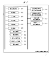
映像表示装置である投影装置1は、図1に示すように、画像入力部101、制御部102、出力部103、通信部104、および記憶部105から構成されている。
As shown in FIG. 1, the projection device 1 that is a video display device includes an image input unit 101, a control unit 102, an output unit 103, a communication unit 104, and a storage unit 105.
また、投影装置1は、カーソル位置認識機能部111、操作可能状態認識機能部112、重畳判定機能部113、応答機能部114、操作モード切り替え機能部115、および操作指示認識機能部116を有する。これらの各機能部は、後述する制御部102が例えばソフトウェアであるプログラムに基づいて実行することにより実現される。
The projection apparatus 1 also includes a cursor position recognition function unit 111, an operable state recognition function unit 112, a superimposition determination function unit 113, a response function unit 114, an operation mode switching function unit 115, and an operation instruction recognition function unit 116. Each of these functional units is realized when the control unit 102 described later executes based on a program that is software, for example.
なお、図1では、上述した各機能部をソフトウェアによって実現するものとしたが、各機能部は、それらの一部またはすべてを、ハードウェアによって実現するようにしてもよい。あるいはハードウェアとソフトウェアとを併用してもよい。
In FIG. 1, each of the functional units described above is realized by software. However, each functional unit may be realized by hardware, part or all of them. Alternatively, hardware and software may be used in combination.
映像生成部となる画像入力部101は、外部もしくは内部からの映像あるいは音声信号を入力することができる接続インタフェースである。この画像入力部101は、RGB入力端子、HDMI(High Definition Multimedia Interface)端子、あるいはUSB(Universal Serial Bus)端子やSDカードスロットなどであってもよい。
The image input unit 101 serving as a video generation unit is a connection interface that can input video or audio signals from the outside or the inside. The image input unit 101 may be an RGB input terminal, an HDMI (High Definition Multimedia Interface) terminal, a USB (Universal Serial Bus) terminal, an SD card slot, or the like.
RGB入力端子は、映像を入力できる端子である。HDMI端子は、デジタル映像や音声などのインタフェース規格に対応した端子であり、外部接続されるハイビジョンモニタなどに動画像を入力する。USB端子は、外部機器との接続端子であり、例えば外部メモリなどに動画像を入力する。SDカードスロットは、SDメモリカードが挿入されるスロットである。
RGB input terminal is a terminal that can input video. The HDMI terminal is a terminal corresponding to an interface standard such as digital video or audio, and inputs a moving image to an externally connected high-vision monitor or the like. The USB terminal is a connection terminal with an external device, and inputs a moving image to an external memory, for example. The SD card slot is a slot into which an SD memory card is inserted.
映像生成部となる制御部102は、後述する通信部104や各機能部などを制御するCPU(Central Processing Unit)やメモリ、およびこれらの周辺機器などにて構成され、プログラムを実行することで様々な機能を実現する。
The control unit 102 serving as a video generation unit includes a CPU (Central Processing Unit) that controls a communication unit 104 and functional units described later, a memory, peripheral devices, and the like. Realize the functions.
映像出力部となる出力部103は、画像入力部101を介して入力される映像信号や音声信号を表示出力する機能を有する。出力部103は、例えば映像を投影するプロジェクタあるいは映像や音声を出力する直視型ディスプレイなどである。
The output unit 103 serving as a video output unit has a function of displaying and outputting a video signal and an audio signal input via the image input unit 101. The output unit 103 is, for example, a projector that projects video or a direct-view display that outputs video and audio.
通信部104は、他の機器から投影装置1の操作指示を受信したり、その応答を送信したりする通信モジュールであり、例えばBluetooth通信に対応する。ここでは、Bluetooth通信によって投影装置1と図2に示す装着型情報処理装置2との間における通信を行うものとするが、通信方式はこれに限定されるものではなく、その他の通信方式であってもよい。
The communication unit 104 is a communication module that receives an operation instruction of the projection apparatus 1 from another device and transmits a response thereof, and corresponds to, for example, Bluetooth communication. Here, the communication between the projection apparatus 1 and the wearable information processing apparatus 2 shown in FIG. 2 is performed by Bluetooth communication, but the communication method is not limited to this, and other communication methods are used. May be.
記憶部105は、情報記憶媒体であり、半導体メモリやHDD(Hard Disc Drive)などから構成される。記憶部105は、投影装置1から取り外せない固定型でもよいし、取り外せるリムーバブル型でもよい。記憶部105は、後述するカーソル位置情報130、認証情報131、ジェスチャパターン情報132、入力画像情報133、および操作可能オブジェクト情報134を格納する。
The storage unit 105 is an information storage medium and includes a semiconductor memory, an HDD (Hard Disc Drive), or the like. The storage unit 105 may be a fixed type that cannot be removed from the projection apparatus 1 or a removable type that can be removed. The storage unit 105 stores cursor position information 130, authentication information 131, gesture pattern information 132, input image information 133, and operable object information 134, which will be described later.
カーソル位置認識機能部111は、記憶部105に格納されている現在のカーソル位置情報130を読み出す。操作可能状態認識機能部112は、カーソルが重畳するオブジェクトが操作可能であるかどうかを判定する。例えば、カーソルが重畳するオブジェクトに関する操作情報1343を記憶部105から読み出し、操作情報1343があるとき、操作可能と判定する。
The cursor position recognition function unit 111 reads the current cursor position information 130 stored in the storage unit 105. The operable state recognition function unit 112 determines whether the object on which the cursor is superimposed is operable. For example, operation information 1343 related to the object on which the cursor is superimposed is read from the storage unit 105, and when there is operation information 1343, it is determined that the operation is possible.
映像生成部重畳判定機能部113は、出力部103を介して表示している映像において、操作可能なオブジェクトを構成する位置情報1341の集合の中に現在のカーソル位置情報130が含まれているかどうかを判定する。
The video generation unit superimposition determination function unit 113 determines whether or not the current cursor position information 130 is included in the set of position information 1341 constituting the operable object in the video displayed via the output unit 103. Determine.
応答機能部114は、通信部104を介して操作に関する事前通知情報1345や中間応答情報1346、および最終応答情報1347を送信する。
The response function unit 114 transmits advance notification information 1345, intermediate response information 1346, and final response information 1347 regarding the operation via the communication unit 104.
操作モード切り替え機能部115は、制御部102からの指示を受けて、操作モードをカーソル操作モード、もしくはジェスチャ操作モードに切り替える。
The operation mode switching function unit 115 receives an instruction from the control unit 102 and switches the operation mode to the cursor operation mode or the gesture operation mode.
カーソル操作モードは、出力部103を介して出力するカーソル画像を単に移動したり、後述する操作可能なオブジェクトを選択したりすることを主目的とする。
The cursor operation mode is mainly intended to simply move the cursor image output via the output unit 103 or to select an operable object described later.
また、ジェスチャ操作モードは、出力部103を介して出力する入力画像情報133の切り替え、進退、および拡大/縮小のほか、入力画像情報133と合成される操作可能なオブジェクト画像に関連づけられた処理の実行をジェスチャで指示することを主目的とする。
The gesture operation mode includes switching of the input image information 133 output via the output unit 103, advance / retreat, and enlargement / reduction, and processing associated with an operable object image to be combined with the input image information 133. The main purpose is to instruct execution using gestures.
操作指示認識機能部116は、記憶部105に格納されているジェスチャパターン情報132と変位情報221との照合を行い、ジェスチャ操作を認識する。カーソル位置情報130は、出力部103を介して投影表示されているカーソルの現在位置を表す座標値である。
The operation instruction recognition function unit 116 compares the gesture pattern information 132 stored in the storage unit 105 with the displacement information 221 and recognizes the gesture operation. The cursor position information 130 is a coordinate value representing the current position of the cursor projected and displayed via the output unit 103.
認証情報131は、投影装置1と装着型情報処理装置2との間で通信可能するための共有データであり、例えば投影装置1や装着型情報処理装置2で入力できるパスワードやPIN(Personal Identification Number)番号などを指す。
The authentication information 131 is shared data for enabling communication between the projection apparatus 1 and the wearable information processing apparatus 2. For example, the authentication information 131 is a password or PIN (Personal Identification 入 力 Number) that can be input by the projection apparatus 1 or the wearable information processing apparatus 2. ) Indicates a number.
操作パターン情報となるジェスチャパターン情報132は、後述する操作指示認識機能部116が認識できるジェスチャ操作の集合である。例えば、初期位置から右方向に変位を検出できた場合には、投影画像を先送りする操作を実行するなど、各ジェスチャ操作には投影装置1を制御する機能が割り当てられている。
The gesture pattern information 132 serving as operation pattern information is a set of gesture operations that can be recognized by an operation instruction recognition function unit 116 described later. For example, when a displacement in the right direction from the initial position can be detected, a function for controlling the projection apparatus 1 is assigned to each gesture operation, such as performing an operation to advance the projection image.
入力画像情報133は、画像入力部101を介して入力された映像や画像である。カーソル画像などを重ね合わせて出力部103を介して出力する投影画像を生成するための基になる画像である。
The input image information 133 is a video or image input via the image input unit 101. This is an image that is a basis for generating a projection image that is output through the output unit 103 by superimposing a cursor image or the like.
操作可能オブジェクト情報134は、操作可能オブジェクトの位置情報1341、操作可能オブジェクトの画像情報1342、および操作可能オブジェクトの操作情報1343によって構成されており、操作可能なオブジェクトの数に応じて複数持つことができる。
The operable object information 134 includes position information 1341 of the operable object, image information 1342 of the operable object, and operation information 1343 of the operable object, and a plurality of the operable object information 134 may be provided depending on the number of operable objects. it can.
操作可能オブジェクトの位置情報1341は、出力部103を介して投影した画像上で、特定の操作の実行指示を割り当てたエリアを示す座標値である。このエリアが多角形の場合は、このエリアを囲む点の座標値の集合として表してもよい。
The position information 1341 of the manipulable object is a coordinate value indicating an area to which a specific operation execution instruction is assigned on the image projected via the output unit 103. When this area is a polygon, it may be expressed as a set of coordinate values of points surrounding this area.
操作可能オブジェクトの画像情報1342は、特定の操作の実行指示を割り当てたエリアを視覚的に示す画像である。画像入力部101を介して入力された映像に重畳して出力部103を介して投影してもよいし、画像情報1342単独で出力部103を介して投影してもよい。
The image information 1342 of the manipulable object is an image that visually indicates an area to which a specific operation execution instruction is assigned. The image input unit 101 may be superimposed on the video input and projected via the output unit 103, or the image information 1342 alone may be projected via the output unit 103.
操作可能オブジェクトの操作情報1343は、実行情報1344、事前通知情報1345、中間応答情報1346、および最終応答情報1347にて構成される。実行情報1344は、制御部102に対して実行する処理を表す情報である。例えば、実行情報1344として電源のオン/オフ、投影の再開中止、投影画面の切り替えや進退、拡大/縮小、音量の増減などの設定変更などを割り当てることができる。
The operation information 1343 of the operable object includes execution information 1344, advance notification information 1345, intermediate response information 1346, and final response information 1347. The execution information 1344 is information representing processing to be executed on the control unit 102. For example, the execution information 1344 can be assigned to power on / off, projection resumption stop, projection screen switching or advance / retreat, enlargement / reduction, volume change, etc.
第1および第2の通知情報となる事前通知情報1345は、操作可能オブジェクトが操作可能な待機状態になったとき、通信部104を介して装着型情報処理装置2に事前通知されるデータである。例えば、ある操作可能オブジェクトの事前通知情報1345に対して1秒間隔で断続的に振動、および事前通知の合計時間は5秒などのデータが指定される。
The prior notification information 1345 serving as the first and second notification information is data that is notified in advance to the wearable information processing apparatus 2 via the communication unit 104 when the operable object enters an operable standby state. . For example, data such as 5 seconds is specified for the prior notification information 1345 of an operable object that is intermittently vibrated at intervals of 1 second and the total time of the prior notification is 5 seconds.
中間応答情報1346は、操作可能オブジェクトに対して操作実行指示があったときに、操作指示の受信や、それ以降に操作が継続する場合の操作指示の実行成否の少なくともいずれかを通信部104を介して装着型情報処理装置2に返送されるデータである。
The intermediate response information 1346 indicates at least one of reception of an operation instruction when an operation execution instruction is given to an operable object, and whether or not the operation instruction is successfully executed when the operation continues thereafter. Data sent back to the wearable information processing apparatus 2 via the network.
例えば、操作指示の受信応答として0.5秒間振動、操作指示を実行した結果、成功であった場合には何もしない、失敗であった場合は弱い鳴動を3秒継続する、などのデータが格納されている。なお、指定内容はこれに限らないし、中間状態が複数ある場合にはこれを複数指定してもよい。
For example, there is data such as vibration for 0.5 seconds as a reception response to an operation instruction, and if the operation instruction is successful, nothing is performed if it is successful, and a weak ringing is continued for 3 seconds if it is unsuccessful. Stored. The specified content is not limited to this, and when there are a plurality of intermediate states, a plurality of specified states may be specified.
最終応答情報1347は、操作可能オブジェクトに対して操作実行指示があったときに、この指示で操作が完結する場合の操作指示の実行成否に関して通信部104を介して装着型情報処理装置2に返送されるデータである。例えば、前述の中間応答情報1346と同種のデータが格納され、中間応答情報1346と同一のデータであってもよい。
The final response information 1347 is returned to the wearable information processing apparatus 2 via the communication unit 104 regarding the success or failure of the operation instruction when the operation is completed by this instruction when an operation execution instruction is given to the operable object. Data. For example, the same kind of data as the intermediate response information 1346 described above may be stored, and the same data as the intermediate response information 1346 may be stored.
このように、投影装置1は、操作指示の実行成否を通知することができるので、投影装置1の動作状態の把握効率を向上することができる。
〈装着型情報処理装置の構成例〉 Thus, since theprojection apparatus 1 can notify the success or failure of the execution of the operation instruction, the grasping efficiency of the operation state of the projection apparatus 1 can be improved.
<Configuration example of wearable information processing device>
〈装着型情報処理装置の構成例〉 Thus, since the
<Configuration example of wearable information processing device>
図2は、本実施の形態1による装着型情報処理装置2における構成の一例を示す説明図である。
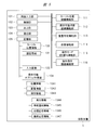
FIG. 2 is an explanatory diagram showing an example of the configuration of the wearable information processing apparatus 2 according to the first embodiment.
ウェアラブルデバイスである装着型情報処理装置2は、図2に示すように、変位検出部201、制御部202、入力部203、出力部204、通信部205、および記憶部206から構成される。
As shown in FIG. 2, the wearable information processing apparatus 2 that is a wearable device includes a displacement detection unit 201, a control unit 202, an input unit 203, an output unit 204, a communication unit 205, and a storage unit 206.
また、装着型情報処理装置2は、変位検出処理実行指示機能部210、傾斜検出処理実行指示機能部211、および応答結果判定機能部212を有する。これらの各機能部は、制御部202が例えばソフトウェアであるプログラムに基づいて実行することにより実現される。なお、図2では、上述した各機能部をソフトウェアによって実現するものとしたが、各機能部は、それらの一部またはすべてを、ハードウェアによって実現するようにしてもよい。あるいはハードウェアとソフトウェアとを併用してもよい。
The wearable information processing apparatus 2 includes a displacement detection process execution instruction function unit 210, an inclination detection process execution instruction function unit 211, and a response result determination function unit 212. Each of these functional units is realized by the control unit 202 executing based on a program that is software, for example. In FIG. 2, each functional unit described above is realized by software, but each functional unit may be realized by hardware, part or all of them. Alternatively, hardware and software may be used in combination.
変位センサである変位検出部201は、装着型情報処理装置2の傾斜や変位を検出できるセンサであり、例えば加速度を検出できる3D加速度センサや、角速度を検出できる3Dジャイロスコープを用いて実現してもよい。
The displacement detection unit 201, which is a displacement sensor, is a sensor that can detect the tilt and displacement of the wearable information processing apparatus 2, and is realized by using, for example, a 3D acceleration sensor that can detect acceleration or a 3D gyroscope that can detect angular velocity. Also good.
制御情報生成部を構成する制御部202は、後述する入力部203や通信部205を制御するCPUやメモリ、これらの周辺機器で構成され、プログラムを実行することで様々な機能を実現する。
The control unit 202 that constitutes the control information generation unit includes a CPU and a memory that control an input unit 203 and a communication unit 205, which will be described later, and these peripheral devices, and implements various functions by executing programs.
接触部である入力部203は、変位検出部201に対して検出処理を実行するタイミングを入力する。例えば押下によって実行タイミングを入力するボタンであってもよいし、特定の指示音声を認識して実行タイミングを入力できるマイクロフォンであってもよい。
The input unit 203 that is a contact unit inputs a timing for executing the detection process to the displacement detection unit 201. For example, it may be a button that inputs an execution timing by pressing, or a microphone that can recognize a specific instruction voice and input the execution timing.
振動発生部となる出力部204は、投影装置1の通信部104から受信した指示に対する応答や処理の成否を表す事前通知情報1345、中間応答情報1346、および最終応答情報1347を出力するためのデバイスである。
The output unit 204 serving as a vibration generating unit is a device for outputting prior notification information 1345, intermediate response information 1346, and final response information 1347 indicating the response to the instruction received from the communication unit 104 of the projection apparatus 1 and the success or failure of the process. It is.
出力部204は、表示にて出力する場合、LED(Light Emitting Diode)など、音声にて出力する場合には、スピーカなどであるが、ここでは、出力部204は、バイブレータなどを想定し、該バイブレータの振動を用いて出力する場合について説明する。
The output unit 204 is a speaker or the like when outputting by sound, such as an LED (Light Emitting Diode) when outputting by display, but here the output unit 204 assumes a vibrator or the like, The case where it outputs using the vibration of a vibrator is demonstrated.
第1の通信部となる通信部205は、変位検出部201が取得した変位情報221や傾斜情報222を投影装置1の通信部104に送信したり、投影装置1の通信部104から指示に対する応答や処理の成否を表す事前通知情報1345、中間応答情報1346、最終応答情報1347を受信したりすることもできる通信モジュールである。ここでは、図1の通信部104と同様、Bluetooth通信を例にとって説明するが、通信部205においても通信方式はこれに限らない。
The communication unit 205 serving as the first communication unit transmits the displacement information 221 and the tilt information 222 acquired by the displacement detection unit 201 to the communication unit 104 of the projection apparatus 1 and responds to instructions from the communication unit 104 of the projection apparatus 1. The communication module can also receive advance notification information 1345 indicating success or failure of processing, intermediate response information 1346, and final response information 1347. Here, as with the communication unit 104 in FIG. 1, Bluetooth communication will be described as an example, but the communication method in the communication unit 205 is not limited to this.
記憶部206は、半導体メモリなどから構成される記憶媒体であり、固定型、リムーバブル型の形態を問わない。記憶部206は、変位情報221、傾斜情報222、操作応答情報223、および操作モード情報224を格納する。
The storage unit 206 is a storage medium composed of a semiconductor memory or the like, and may be a fixed type or a removable type. The storage unit 206 stores displacement information 221, inclination information 222, operation response information 223, and operation mode information 224.
変位情報221は、変位検出部201が取得できる装着型情報処理装置2の変位を示すデータである。傾斜情報222は、変位検出部201が取得できる装着型情報処理装置2の傾斜を示すデータである。
The displacement information 221 is data indicating the displacement of the wearable information processing apparatus 2 that can be acquired by the displacement detection unit 201. The inclination information 222 is data indicating the inclination of the wearable information processing apparatus 2 that can be acquired by the displacement detection unit 201.
操作応答情報223は、通信部205を介して投影装置1から受信した事前通知情報1345、中間応答情報1346、および最終応答情報1347を示す。操作モード情報224は、装着型情報処理装置2の現在の操作目的が投影装置1上のカーソルを操作するためのカーソル操作モードであるか、投影装置1を操作するためのジェスチャ操作モードであるかを表すデータである。操作モード情報224におけるカーソル操作モードを表すデータが第1の制御情報となり、ジェスチャ操作モードを表すデータが第2の制御情報となる。
The operation response information 223 indicates prior notification information 1345, intermediate response information 1346, and final response information 1347 received from the projection apparatus 1 via the communication unit 205. Whether the operation mode information 224 is a cursor operation mode for operating the cursor on the projection apparatus 1 or a gesture operation mode for operating the projection apparatus 1 is the current operation purpose of the wearable information processing apparatus 2 It is data representing. Data representing the cursor operation mode in the operation mode information 224 is the first control information, and data representing the gesture operation mode is the second control information.
認証情報225は、通信部205が他の機器と通信するために共有するパスワードやPIN情報などである。変位検出処理実行指示機能部210は、入力部203に対して入力があったときに、変位検出部201に対して変位の検出処理の実行を指示する。
The authentication information 225 is a password, PIN information, or the like shared for the communication unit 205 to communicate with other devices. The displacement detection process execution instruction function unit 210 instructs the displacement detection unit 201 to execute a displacement detection process when an input is made to the input unit 203.
入力部203に入力がないときは、変位検出処理実行指示機能部210は変位検出部201の変位検出処理を停止してもよいし、変位検出部201から検出済みの変位データを取得する処理を停止してもよい。あるいは、記憶部206に変位情報221として格納する処理を停止してもよい。
When there is no input to the input unit 203, the displacement detection process execution instruction function unit 210 may stop the displacement detection process of the displacement detection unit 201, or perform a process of acquiring detected displacement data from the displacement detection unit 201. You may stop. Alternatively, the process of storing the displacement information 221 in the storage unit 206 may be stopped.
傾斜検出処理実行指示機能部211は、入力部203に対して入力があったときに、変位検出部201に対して傾斜の検出処理の実行を指示する。入力部203に入力がないときは、変位検出処理実行指示機能部210は変位検出部201の傾斜検出処理を停止してもよいし、変位検出部201から検出済みの傾斜データを取得する処理を停止してもよい。または記憶部206に傾斜情報222として格納する処理を停止してもよい。
The tilt detection process execution instruction function unit 211 instructs the displacement detection unit 201 to execute a tilt detection process when an input is made to the input unit 203. When there is no input to the input unit 203, the displacement detection process execution instruction function unit 210 may stop the inclination detection process of the displacement detection unit 201, or perform a process of acquiring detected inclination data from the displacement detection unit 201. You may stop. Or you may stop the process stored in the memory | storage part 206 as the inclination information 222. FIG.
応答結果判定機能部212は、投影装置1の通信部104を介して受信した事前通知情報1345、中間応答情報1346、および最終応答情報1347を解析し、指示した処理の成否を判定する。
The response result determination function unit 212 analyzes the prior notification information 1345, the intermediate response information 1346, and the final response information 1347 received via the communication unit 104 of the projection apparatus 1, and determines the success or failure of the instructed process.
制御情報生成部を構成する操作モード判定機能部213は、記憶部206に格納されている傾斜情報222のデータに応じて、現在の操作モードがカーソル操作モードなのかジェスチャ操作モードなのかを判定する。
The operation mode determination function unit 213 constituting the control information generation unit determines whether the current operation mode is the cursor operation mode or the gesture operation mode according to the data of the inclination information 222 stored in the storage unit 206. .
続いて、装着型情報処理装置2および投影装置1における動作について説明する。ここでは、投影装置1と装着型情報処理装置2の無線接続の確立を以て、装着型情報処理装置2から投影装置1を遠隔操作する例について説明する。
〈装着型情報処理装置の処理例〉 Next, operations in the wearableinformation processing apparatus 2 and the projection apparatus 1 will be described. Here, an example in which the projection apparatus 1 is remotely operated from the wearable information processing apparatus 2 by establishing a wireless connection between the projection apparatus 1 and the wearable information processing apparatus 2 will be described.
<Processing example of wearable information processing device>
〈装着型情報処理装置の処理例〉 Next, operations in the wearable
<Processing example of wearable information processing device>
図3は、図2の装着型情報処理装置2による処理の一例を示すフローチャートである。
FIG. 3 is a flowchart showing an example of processing by the wearable information processing apparatus 2 of FIG.
この図3は、投影装置1を操作する場合の装着型情報処理装置2による処理の一例を示したものである。
FIG. 3 shows an example of processing by the wearable information processing apparatus 2 when operating the projection apparatus 1.
まず、通信部205を介して投影装置1とBluetooth通信におけるペアリング処理を完了し、通信可能になっている状態を開始状態とする。このとき、Bluetooth通信を利用する場合に、認証情報225は、通信部205を介して通信可能な投影装置1へ共有されている。
First, the pairing process in the Bluetooth communication with the projection apparatus 1 is completed via the communication unit 205, and a state where communication is possible is set as a start state. At this time, when using Bluetooth communication, the authentication information 225 is shared via the communication unit 205 to the communicable projection apparatus 1.
続いて、制御部202は、入力部203に対して入力があるかどうかを判定する(ステップS101)。これ以降、入力部203をボタンにて実現した例を説明する。
Subsequently, the control unit 202 determines whether or not there is an input to the input unit 203 (step S101). Hereinafter, an example in which the input unit 203 is realized with buttons will be described.
入力部203に押下入力、すなわちボタンが押下された場合、制御部202は、ボタンの押下中、もしくはボタン押下の直後から一定時間に限って傾斜検出処理実行指示機能部211、および変位検出処理実行指示機能部210に対して実行を指示する。傾斜検出処理実行指示機能部211は、変位検出部201が採取した傾斜データを取得して、記憶部206に傾斜情報222として格納する。
When the input is performed on the input unit 203, that is, when a button is pressed, the control unit 202 performs the inclination detection process execution instruction function unit 211 and the displacement detection process execution only during a predetermined time from the time the button is pressed or immediately after the button is pressed. The instruction function unit 210 is instructed to execute. The inclination detection processing execution instruction function unit 211 acquires the inclination data collected by the displacement detection unit 201 and stores it in the storage unit 206 as inclination information 222.
このように、ボタンの押下中、もしくはボタン押下の直後から一定時間に限って変位検出部201が採取した傾斜データを取り込むことによって、操作モードの誤認識を低減することができる。
As described above, the misrecognition of the operation mode can be reduced by capturing the inclination data collected by the displacement detection unit 201 only during a certain time from when the button is pressed or immediately after the button is pressed.
そして、操作モード判定機能部213は、記憶部206に格納された傾斜情報222のデータから、現在の操作モードがカーソル操作モードなのか、ジェスチャ操作モードなのかを判定し、その判定結果を記憶部206に操作モード情報224として格納する(ステップS102)。
Then, the operation mode determination function unit 213 determines whether the current operation mode is the cursor operation mode or the gesture operation mode from the data of the inclination information 222 stored in the storage unit 206, and the determination result is stored in the storage unit The operation mode information 224 is stored in 206 (step S102).
例えば、傾斜情報222から装着型情報処理装置2が水平方向に向いていると認識した場合には、遠隔の投影装置1に表示した投影物を指し示すためのカーソル操作モードと判定する。
For example, when it is recognized from the tilt information 222 that the wearable information processing apparatus 2 is oriented in the horizontal direction, the cursor operation mode for pointing to the projection displayed on the remote projection apparatus 1 is determined.
また、垂直方向に向いていると認識した場合には、遠隔の投影装置1を操作するためのジェスチャ操作モードであると判定する。このように装着型情報処理装置2の傾斜に応じて操作モードを替えられればよく、この例に限るものではない。
Also, when it is recognized that it is oriented in the vertical direction, it is determined that it is a gesture operation mode for operating the remote projector 1. Thus, it is only necessary to change the operation mode according to the inclination of the wearable information processing apparatus 2, and the present invention is not limited to this example.
傾斜判定処理の後、変位検出処理実行指示機能部210は、変位検出部201で採取した変位データを記憶部206に変位情報221として格納し、操作モード情報224と併せて、通信部205を介して投影装置1に送信する(ステップS103)。
After the tilt determination process, the displacement detection process execution instruction function unit 210 stores the displacement data collected by the displacement detection unit 201 in the storage unit 206 as displacement information 221, together with the operation mode information 224, via the communication unit 205. To the projection apparatus 1 (step S103).
制御部202は、通信部205を介して投影装置1からの応答を受信したかどうか判定する(ステップS104)。判定の結果、応答を受信した場合には、操作応答情報223として記憶部206に格納し、操作応答情報223に基づいて出力部204を介して応答を出力する(ステップS105)。このとき、応答として事前通知情報1345、中間応答情報1346、または最終応答情報1347のいずれかが含まれる。
The control unit 202 determines whether a response from the projection apparatus 1 has been received via the communication unit 205 (step S104). As a result of the determination, when a response is received, the response is stored in the storage unit 206 as the operation response information 223, and the response is output via the output unit 204 based on the operation response information 223 (step S105). At this time, any of the prior notification information 1345, the intermediate response information 1346, and the final response information 1347 is included as a response.
また、応答結果判定機能部212は、事前通知情報1345、中間応答情報1346、または最終応答情報1347の内容を解析し、指示した処理の成否を判定してもよい。この判定の結果、成否に応じて出力部204に対して既定の出力を指示してもよいし、応答結果判定機能部212は判定を行わずに、事前通知情報1345、中間応答情報1346、最終応答情報1347に含まれるバイブレータである出力部204の鳴動時間に関するデータなどに従って出力部204を制御してもよい。
Further, the response result determination function unit 212 may analyze the contents of the prior notification information 1345, the intermediate response information 1346, or the final response information 1347 and determine the success or failure of the instructed process. As a result of this determination, a predetermined output may be instructed to the output unit 204 according to success or failure, and the response result determination function unit 212 does not make a determination, but the advance notification information 1345, the intermediate response information 1346, the final You may control the output part 204 according to the data regarding the ringing time of the output part 204 which is a vibrator contained in the response information 1347, etc. FIG.
応答を受信しない場合には、特に応答に応じた出力はせずに、入力部203に対して入力が継続されているかどうかを判定する(ステップS106)。判定の結果、入力が継続されている場合には、ステップS103の処理に戻って変位情報221および傾斜情報222の送信を継続する。
If no response is received, it is determined whether or not input to the input unit 203 is continued without particularly outputting according to the response (step S106). If the input is continued as a result of the determination, the process returns to the process of step S103 and the transmission of the displacement information 221 and the inclination information 222 is continued.
一方、入力が継続していない場合には、ステップS101の処理に戻って、次に入力部203に対して入力があるまで待機する。
〈投影装置の処理例〉 On the other hand, if the input is not continued, the process returns to step S101 and waits until there is an input to theinput unit 203 next.
<Example of processing of the projection device>
〈投影装置の処理例〉 On the other hand, if the input is not continued, the process returns to step S101 and waits until there is an input to the
<Example of processing of the projection device>
図4は、投影装置1による処理の一例を示すフローチャートである。前述したように、投影装置1は、装着型情報処理装置2から指示を受けて操作される。
FIG. 4 is a flowchart showing an example of processing by the projection apparatus 1. As described above, the projection apparatus 1 is operated in response to an instruction from the wearable information processing apparatus 2.
まず、図3の開始状態と同様に、投影装置1は、装着型情報処理装置2と通信部104を介して接続するためのペアリング処理が完了している状態を開始状態とする。このとき、Bluetooth通信を利用する場合は、認証情報131は通信部104を介して通信可能な装着型情報処理装置2へ共有されている。
First, similarly to the start state of FIG. 3, the projection apparatus 1 sets a start state in which a pairing process for connecting to the wearable information processing apparatus 2 via the communication unit 104 is completed. At this time, when using Bluetooth communication, the authentication information 131 is shared via the communication unit 104 to the wearable information processing apparatus 2 that can communicate.
続いて、制御部102は、装着型情報処理装置2の通信部205から送信される変位情報221および傾斜情報222を通信部104が受信しているかどうか判定する(ステップS201)。受信している場合は、ステップS202の処理に進む。一方、受信していない場合は、ステップS201の処理に戻り、受信を待機する。
Subsequently, the control unit 102 determines whether the communication unit 104 has received the displacement information 221 and the tilt information 222 transmitted from the communication unit 205 of the wearable information processing apparatus 2 (step S201). If received, the process proceeds to step S202. On the other hand, if it has not been received, the process returns to step S201 to wait for reception.
変位情報221および傾斜情報222を通信部104が受信している場合、受信した傾斜情報222に基づいて、操作モードの判定を行う(ステップS202)。例えば、受信した傾斜情報222が装着型情報処理装置2として水平方向を指している場合、制御部102は、操作モード切り替え機能部115を制御して、操作モードをカーソル操作モードに切り替えて、ステップS203の処理に進む。
When the communication unit 104 has received the displacement information 221 and the inclination information 222, the operation mode is determined based on the received inclination information 222 (step S202). For example, when the received tilt information 222 indicates the horizontal direction as the wearable information processing apparatus 2, the control unit 102 controls the operation mode switching function unit 115 to switch the operation mode to the cursor operation mode. The process proceeds to S203.
一方、傾斜情報222が装着型情報処理装置2の向きとして垂直方向を指していることを表している場合、制御部102は、操作モード切り替え機能部115を制御して、操作モードをジェスチャ操作モードに切り替えて、ステップS209の処理に進む。
On the other hand, when the tilt information 222 indicates that the orientation of the wearable information processing apparatus 2 indicates the vertical direction, the control unit 102 controls the operation mode switching function unit 115 to change the operation mode to the gesture operation mode. The process proceeds to step S209.
ステップS202の処理における操作モードの判定において、傾斜情報222が装着型情報処理装置2として水平方向を指している場合には、受信した変位情報221に基づいて、カーソルの変位を算出する(ステップS203)。
In the determination of the operation mode in the process of step S202, if the tilt information 222 indicates the horizontal direction as the wearable information processing apparatus 2, the displacement of the cursor is calculated based on the received displacement information 221 (step S203). ).
例えば、変位情報221は、3軸方向の加速度値として表される場合、それらの値を積分することで各軸における移動距離を算出することができる。この移動距離値に対してカーソルの移動速度を表す係数を乗算し、カーソルの移動距離に変換する方法があるが、算出方法はこれに限らない。
For example, when the displacement information 221 is expressed as an acceleration value in the triaxial direction, the movement distance in each axis can be calculated by integrating these values. There is a method of multiplying the moving distance value by a coefficient representing the moving speed of the cursor and converting it to a moving distance of the cursor, but the calculation method is not limited to this.
続いて、制御部102は、記憶部105に格納されている現在のカーソル位置情報130に前述のカーソルの移動距離を加算して、カーソル位置情報130を更新する(ステップS204)。
Subsequently, the control unit 102 updates the cursor position information 130 by adding the above-described cursor movement distance to the current cursor position information 130 stored in the storage unit 105 (step S204).
そして、制御部102は、更新されたカーソル位置情報130に基づいて、カーソル画像を生成し、画像入力部101に入力された入力画像情報133と合成した後、出力部103を介して出力する(ステップS205)。
Then, the control unit 102 generates a cursor image based on the updated cursor position information 130, combines it with the input image information 133 input to the image input unit 101, and then outputs it via the output unit 103 ( Step S205).
続いて、制御部102は、重畳判定を行う(ステップS206)。制御部202による重畳判定は、以下に説明するようにカーソル位置を認識し、操作可能なオブジェクトの画像情報1342とカーソル位置が重なっているかどうかを判定する。この場合、オブジェクトとは、例えば操作が割り当てられた画面上のメニューやボタンなどである。
Subsequently, the control unit 102 performs superimposition determination (step S206). The superimposition determination by the control unit 202 recognizes the cursor position as described below, and determines whether or not the image information 1342 of the operable object and the cursor position overlap. In this case, the object is, for example, a menu or button on the screen to which an operation is assigned.
まず、カーソル位置認識機能部111は、記憶部105に格納されている現在のカーソル位置情報130を読み出す。続いて、重畳判定機能部113は、出力部103を介して表示している映像において、操作可能なオブジェクトを構成する位置情報1341の集合の中に現在のカーソル位置情報130が含まれているかどうかを判定する。以上によって重畳判定が終了となる。
First, the cursor position recognition function unit 111 reads the current cursor position information 130 stored in the storage unit 105. Subsequently, the superimposition determination function unit 113 determines whether or not the current cursor position information 130 is included in the set of position information 1341 constituting the operable object in the video displayed via the output unit 103. Determine. Thus, the superimposition determination is completed.
続いて、重畳判定の結果、カーソル位置が重畳している場合、操作可能状態認識機能部112は、カーソルが重畳する操作可能なオブジェクトが操作可能であるかどうかを判定する(ステップS207)。
Subsequently, when the cursor position is superimposed as a result of the superimposition determination, the operable state recognition function unit 112 determines whether or not the operable object on which the cursor is superimposed is operable (step S207).
例えば、カーソルが重畳するオブジェクトに関する操作情報1343を記憶部105から読み出し、操作情報1343に事前通知情報1345が含まれない場合、ステップS201の処理に戻る。
For example, when the operation information 1343 related to the object on which the cursor is superimposed is read from the storage unit 105 and the operation information 1343 does not include the advance notification information 1345, the process returns to the process of step S201.
また、操作情報1343に事前通知情報1345もしくは中間応答情報1346が含まれる場合、応答機能部114は、通信部104を介して事前通知情報1345、もしくは中間応答情報1346の内容を装着型情報処理装置2に送信した後(ステップS208)、ステップS201の処理に戻る。
When the operation information 1343 includes the advance notification information 1345 or the intermediate response information 1346, the response function unit 114 transmits the content of the advance notification information 1345 or the intermediate response information 1346 via the communication unit 104. 2 (step S208), the process returns to step S201.
ステップS202の処理において、ジェスチャ操作モードに切り替えた場合、操作指示認識機能部116は、記憶部105に格納されているジェスチャパターン情報132と変位情報221との照合を行い、ジェスチャ操作を認識する処理を実行する(ステップS209)。
When switching to the gesture operation mode in the process of step S202, the operation instruction recognition function unit 116 performs a process of recognizing the gesture operation by comparing the gesture pattern information 132 stored in the storage unit 105 with the displacement information 221. Is executed (step S209).
ジェスチャ認識に失敗した場合は、ステップS201の処理に戻って通信部104を介して変位情報221を受信し続け、ジェスチャ操作の認識を続ける。このとき、既定の回数以上失敗する、もしくは既定の時間以上ジェスチャ操作を認識できない場合には、操作モード切り替え機能部115が操作モードをカーソル操作モードに切り替えてもよい。また、ジェスチャ認識に失敗した場合、応答機能部114が通信部104を介して認識失敗の応答を装着型情報処理装置2へ送信してもよい。
If the gesture recognition has failed, the process returns to step S201 and continues to receive the displacement information 221 via the communication unit 104 and continues to recognize the gesture operation. At this time, if the operation fails for a predetermined number of times or if the gesture operation cannot be recognized for a predetermined time or more, the operation mode switching function unit 115 may switch the operation mode to the cursor operation mode. When the gesture recognition fails, the response function unit 114 may transmit a recognition failure response to the wearable information processing apparatus 2 via the communication unit 104.
ステップS209の処理においてジェスチャ操作を認識できた場合、応答機能部114は、通信部104を介して認識成功の応答を装着型情報処理装置2に送信する(ステップS210)。
When the gesture operation can be recognized in the process of step S209, the response function unit 114 transmits a response of recognition success to the wearable information processing apparatus 2 via the communication unit 104 (step S210).
続いて、制御部102は、認識したジェスチャ操作に関連づけられた実行情報1344に記述された操作を実行する(ステップS211)。これより後、同一の操作可能オブジェクトに関して、継続的に操作が可能な状態かどうか判定する(ステップS212)。
Subsequently, the control unit 102 executes the operation described in the execution information 1344 associated with the recognized gesture operation (step S211). Thereafter, it is determined whether or not the same operable object can be continuously operated (step S212).
継続的に操作可能な場合、応答機能部114は、中間応答情報1346を装着型情報処理装置2に送信する(ステップS208)。
If the operation is continuously possible, the response function unit 114 transmits the intermediate response information 1346 to the wearable information processing apparatus 2 (step S208).
一方、継続的に操作可能な状態ではなく、操作がこれにて完了する場合、応答機能部114は、通信部104を介して、一連の操作の最終結果である最終応答情報1347を装着型情報処理装置2に送信した後(ステップS213)、ステップS201の処理に戻って変位情報の受信を継続する。
On the other hand, when the operation is not completed and the operation is completed, the response function unit 114 sends the final response information 1347, which is the final result of a series of operations, via the communication unit 104 to the wearable information. After transmitting to the processing apparatus 2 (step S213), the process returns to the process of step S201 and continues to receive the displacement information.
ここで、継続的に操作可能な状態の処理例について、同じく図4を用いて詳細に説明する。
Here, an example of processing in a state where it can be continuously operated will be described in detail with reference to FIG.
継続的に操作可能な状態の処理としては、例えば複数段階の処理にて構成されるドラッグアンドドロップが挙げられる。
As a process in a state where it can be operated continuously, for example, a drag-and-drop process composed of a plurality of stages is exemplified.
このドラッグアンドドロップ操作の処理は、ユーザがあるオブジェクトを選択する第1の処理、その次にオブジェクトの位置を動かして変更する第2の処理、最後にオブジェクトを離して位置を決定する第3の処理、といった3段階の処理にて構成される。
This drag-and-drop operation process includes a first process in which the user selects an object, a second process in which the position of the object is moved and changed, and a third process in which the object is finally released to determine the position. It consists of three stages of processing.
はじめに、第1の処理について説明する。
First, the first process will be described.
まず、オブジェクトを選択する前は、装着型情報処理装置2がカーソル操作モードにて動作しているものとする。投影装置1は、カーソルモードで動作している装着型情報処理装置2の変位を受信し(ステップS201)、装着型情報処理装置2の傾斜情報から操作モードを判定する(ステップS202)。このとき、依然としてカーソル操作モードであると判定すれば、変位情報からカーソル位置を算出する(ステップS203)。
First, it is assumed that the wearable information processing apparatus 2 is operating in the cursor operation mode before selecting an object. The projection apparatus 1 receives the displacement of the wearable information processing apparatus 2 operating in the cursor mode (step S201), and determines the operation mode from the tilt information of the wearable information processing apparatus 2 (step S202). At this time, if the cursor operation mode is still determined, the cursor position is calculated from the displacement information (step S203).
続いて、カーソル位置を更新し(ステップS204)、カーソルの画像と投影する画像を合成して出力する(ステップS205)。そして、カーソルの位置があるオブジェクトと重畳しているかどうかを判定する(ステップS206)。
Subsequently, the cursor position is updated (step S204), and the cursor image and the projected image are combined and output (step S205). Then, it is determined whether or not the cursor is superimposed on the object with the position (step S206).
あるオブジェクトとカーソル位置とが重畳している場合は、そのオブジェクトが操作可能かどうかを判定し(ステップS207)、操作可能であるならば、装着型情報処理装置2にドラッグアンドドロップが可能である旨の通知を行う(ステップS208)。この場合、出力部204が出力する1秒振動などの事前通知情報1345が装着型情報処理装置2に送信される。
If an object and the cursor position are superimposed, it is determined whether or not the object can be operated (step S207). If the object can be operated, drag and drop can be performed on the wearable information processing apparatus 2. Notification to that effect is made (step S208). In this case, prior notification information 1345 such as 1-second vibration output from the output unit 204 is transmitted to the wearable information processing apparatus 2.
これにより、ユーザは、ドラッグアンドドロップが可能であることを装着型情報処理装置2の振動により認識し、該装着型情報処理装置2の傾斜を変えることによりジェスチャ操作モードに切り替える。なお、切り替えない場合は、カーソル操作モードを継続し、カーソル位置の更新を継続する。
Thereby, the user recognizes that the drag-and-drop is possible by the vibration of the wearable information processing apparatus 2, and switches to the gesture operation mode by changing the inclination of the wearable information processing apparatus 2. If not switched, the cursor operation mode is continued and the cursor position is continuously updated.
投影装置1は、装着型情報処理装置2からの変位情報を受信し(ステップS201)、傾斜情報の内容に基づいて、操作モードを判定する(ステップS202)。そして、装着型情報処理装置2の変位情報の軌跡や履歴から、オブジェクトの選択を示すジェスチャ操作を認識できるか判定する(ステップS209)。この場合のジェスチャ操作は、例えば引っ張るような仕草などである。
The projection apparatus 1 receives the displacement information from the wearable information processing apparatus 2 (step S201), and determines the operation mode based on the content of the tilt information (step S202). Then, it is determined whether or not the gesture operation indicating the selection of the object can be recognized from the locus or history of the displacement information of the wearable information processing device 2 (step S209). The gesture operation in this case is, for example, a pulling gesture.
選択を示すジェスチャを認識できなかった場合は、ステップS201の処理に戻って継続して変位を受信する。また、選択を示すジェスチャ認識が成功した場合には、成功した旨の応答を装着型情報処理装置2に送信する(ステップS210)。
If the gesture indicating selection has not been recognized, the process returns to step S201 to continuously receive the displacement. If the gesture recognition indicating selection is successful, a response indicating success is transmitted to the wearable information processing apparatus 2 (step S210).
その後、認識したジェスチャ操作に関連する処理を実行し(ステップS211)、ドラッグアンドドロップ操作に継続操作があるかどうかを判定する(ステップS212)。このステップS212の処理では、制御部102が中間応答情報1346の情報に基づいて判定する。
Thereafter, processing related to the recognized gesture operation is executed (step S211), and it is determined whether there is a continuation operation in the drag and drop operation (step S212). In the process of step S212, the control unit 102 makes a determination based on the information in the intermediate response information 1346.
ドラッグアンドドロップ操作には、オブジェクトを選択した後にオブジェクトを動かすという後続操作があるので、今オブジェクトを動かせるタイミングである、という旨の事前通知情報1345が送信される(ステップS208)。この事前通知情報1345に基づいて、装着型情報処理装置2が振動してオブジェクトを動かせるタイミングであることがユーザに通知される。
In the drag and drop operation, since there is a subsequent operation of moving the object after selecting the object, advance notification information 1345 indicating that it is time to move the object is transmitted (step S208). Based on this prior notification information 1345, the user is notified that it is time to allow the wearable information processing apparatus 2 to vibrate and move the object.
続いて、第2の処理について説明する。
Subsequently, the second process will be described.
ユーザは、その通知を受けて、装着型情報処理装置2の傾斜を変えてカーソル操作モードに切り替える。その後、ユーザは、装着型情報処理装置2を動かして、オブジェクトをドラッグ移動させるために装着型情報処理装置2の変位を送信する。
The user receives the notification and changes the inclination of the wearable information processing apparatus 2 to switch to the cursor operation mode. Thereafter, the user moves the wearable information processing apparatus 2 and transmits the displacement of the wearable information processing apparatus 2 in order to drag the object.
投影装置1は、装着型情報処理装置2から該装着型情報処理装置2の変位を受信し(ステップS201)、装着型情報処理装置2の傾斜情報から操作モードを判定する(ステップS202)。
The projection device 1 receives the displacement of the wearable information processing device 2 from the wearable information processing device 2 (step S201), and determines the operation mode from the tilt information of the wearable information processing device 2 (step S202).
その後、カーソルの位置を更新し(ステップS203,S204)、オブジェクトの移動に関する合成画像を作成した後(ステップS205)、重畳判定を行う(ステップS206)。
Thereafter, the position of the cursor is updated (steps S203 and S204), a composite image relating to the movement of the object is created (step S205), and a superimposition determination is performed (step S206).
重畳判定の結果、続く操作であるオブジェクトのドロップ操作が可能な位置にカーソルが重畳しており、ドロップ操作が可能であると判定した場合には(ステップS207)、ドロップできる旨の事前通知情報1345による通知を装着型情報処理装置2に対して行う(ステップS208)。
続いて、第3の処理を行う。 As a result of the superimposition determination, when it is determined that the cursor is superimposed at a position where the subsequent object drop operation can be performed and the drop operation is possible (step S207),prior notification information 1345 that the drop can be performed. Is sent to the wearable information processing apparatus 2 (step S208).
Subsequently, a third process is performed.
続いて、第3の処理を行う。 As a result of the superimposition determination, when it is determined that the cursor is superimposed at a position where the subsequent object drop operation can be performed and the drop operation is possible (step S207),
Subsequently, a third process is performed.
ユーザは、その通知を受けて、装着型情報処理装置2の傾斜を変えてジェスチャ操作モードに切り替える。続いて、オブジェクトをドロップするジェスチャ操作を行って、装着型情報処理装置2の変位を送信する。この場合のジェスチャ操作は、例えば、前に突き出すような動きである。
Upon receiving the notification, the user changes the inclination of the wearable information processing apparatus 2 and switches to the gesture operation mode. Subsequently, a gesture operation for dropping the object is performed, and the displacement of the wearable information processing apparatus 2 is transmitted. The gesture operation in this case is, for example, a movement that protrudes forward.
投影装置1は、変位と傾斜情報を受信し、操作モードがジェスチャ操作モードであると判定した場合には、変位情報からドロップのジェスチャ操作を認識する(ステップS201~S210)。ここで、ジェスチャ操作は、キャンセルのジェスチャ操作などもありえる。
The projection apparatus 1 receives the displacement and inclination information, and recognizes the drop gesture operation from the displacement information when determining that the operation mode is the gesture operation mode (steps S201 to S210). Here, the gesture operation may be a cancel gesture operation.
認識が成功した場合には、認識成功の通知を行い(ステップS210)、投影装置1はドロップ処理を行う(ステップS211)。
If the recognition is successful, the recognition success is notified (step S210), and the projection apparatus 1 performs a drop process (step S211).
この場合、ドラッグアンドドロップ操作では、継続操作がないため(ステップS212)、装着型情報処理装置2に対して最終応答情報1347を送信する(ステップS213)。以上により、ドラッグアンドドロップの処理がすべて終了となる。
In this case, since there is no continuation operation in the drag-and-drop operation (step S212), final response information 1347 is transmitted to the wearable information processing apparatus 2 (step S213). As described above, all the drag-and-drop processes are completed.
以上により、装着型情報処理装置2の傾斜情報と入力に基づいてカーソル操作モードとジェスチャ操作モードとを投影装置1側にて迅速に切り替えることができる。さらに、装着型情報処理装置2の変位情報や傾斜情報に基づいて、投影装置1におけるカーソルによる投影画像上の指示操作と投影画像の出力制御操作の両方を実行することができる。
As described above, the cursor operation mode and the gesture operation mode can be quickly switched on the projection apparatus 1 side based on the tilt information and input of the wearable information processing apparatus 2. Furthermore, based on the displacement information and the tilt information of the wearable information processing device 2, both the instruction operation on the projection image and the output control operation of the projection image by the cursor in the projection device 1 can be executed.
これらによって、投影装置1における操作の効率性を向上することができる。
(実施の形態2) By these, the operation efficiency in theprojection apparatus 1 can be improved.
(Embodiment 2)
(実施の形態2) By these, the operation efficiency in the
(Embodiment 2)
本実施の形態2では、投影装置1と装着型情報処理装置2との無線接続の確立を以て、装着型情報処理装置2から投影装置1を遠隔操作する他の例について説明する。
〈投影装置の構成例〉 In the second embodiment, another example in which theprojection apparatus 1 is remotely operated from the wearable information processing apparatus 2 by establishing a wireless connection between the projection apparatus 1 and the wearable information processing apparatus 2 will be described.
<Configuration example of the projection device>
〈投影装置の構成例〉 In the second embodiment, another example in which the
<Configuration example of the projection device>
図5は、本実施の形態2による投影装置1における構成の一例を示す説明図である。
FIG. 5 is an explanatory diagram showing an example of the configuration of the projection apparatus 1 according to the second embodiment.
図5の投影装置1が前記実施の形態1の図1の投影装置1と異なる点は、図1の投影装置1が有するジェスチャパターン情報132が具備されていないところである。その他の構成については、前記実施の形態1の図1と同様であるので、説明は省略する。
〈装着型情報処理装置の構成例〉 Theprojector 1 of FIG. 5 is different from the projector 1 of FIG. 1 of the first embodiment in that the gesture pattern information 132 included in the projector 1 of FIG. 1 is not provided. Other configurations are the same as those of the first embodiment shown in FIG.
<Configuration example of wearable information processing device>
〈装着型情報処理装置の構成例〉 The
<Configuration example of wearable information processing device>
図6は、本実施の形態2よる装着型情報処理装置2における構成の一例を示す説明図である。
FIG. 6 is an explanatory diagram showing an example of the configuration of the wearable information processing apparatus 2 according to the second embodiment.
図6の装着型情報処理装置2は、前記実施の形態1の図2の装着型情報処理装置2の構成に加えて、操作指示認識機能部214、操作指示送信機能部215、およびジェスチャパターン情報226が新たに設けられている。操作指示認識機能部214および操作指示送信機能部215は、前記実施の形態1と同様に、制御部202が例えばソフトウェアであるプログラムに基づいて実行することにより実現される。
The wearable information processing apparatus 2 of FIG. 6 has an operation instruction recognition function unit 214, an operation instruction transmission function part 215, and gesture pattern information in addition to the configuration of the wearable information processing apparatus 2 of FIG. 2 of the first embodiment. 226 is newly provided. As in the first embodiment, the operation instruction recognition function unit 214 and the operation instruction transmission function unit 215 are realized by the control unit 202 executing based on a program that is software, for example.
この変更によって生じる差異を以下に説明する。
〈装着型情報処理装置の処理例〉 Differences caused by this change will be described below.
<Processing example of wearable information processing device>
〈装着型情報処理装置の処理例〉 Differences caused by this change will be described below.
<Processing example of wearable information processing device>
図7は、図6の装着型情報処理装置2による処理の一例を示すフローチャートである。この図7では、投影装置1を操作する装着型情報処理装置2における処理例を示している。
FIG. 7 is a flowchart showing an example of processing by the wearable information processing apparatus 2 of FIG. FIG. 7 shows a processing example in the wearable information processing apparatus 2 that operates the projection apparatus 1.
ここで、図7における開始状態、ステップS301の処理、およびステップS303~S306の処理は、前記実施の形態1の図3の開始状態、ステップS101の処理、およびステップS103~S106の処理と同様であるので説明は省略する。よって、ここでは、図3との差異であるステップS302の処理、およびS307~S312の処理にいて説明する。
Here, the start state in FIG. 7, the process in step S301, and the processes in steps S303 to S306 are the same as the start state in FIG. 3 in the first embodiment, the process in step S101, and the processes in steps S103 to S106. Since there is, explanation is omitted. Therefore, here, the processing of step S302 and the processing of S307 to S312 which are differences from FIG. 3 will be described.
まず、ステップS301の処理において、入力部203へ押下入力があった場合、操作モード判定機能部213は、現在の装着型情報処理装置2における操作モードの判定を行い(ステップS302)、判定結果を操作モード情報224として格納する。
First, in the process of step S301, when there is a pressing input to the input unit 203, the operation mode determination function unit 213 determines the operation mode in the current wearable information processing apparatus 2 (step S302), and displays the determination result. Stored as operation mode information 224.
図3のステップS102の処理と同様に、傾斜データなどから操作モードがカーソル操作モードであると判定した場合には、ステップS303の処理に進む。
3, when it is determined from the tilt data or the like that the operation mode is the cursor operation mode, the process proceeds to step S303 as in the process of step S102 of FIG.
一方、操作モードがジェスチャ操作モードであると判定すると、装着型情報処理装置2の操作指示認識機能部214は、変位検出部201から取得した変位情報221、および傾斜情報222に基づいてジェスチャパターン情報226との照合を行う(ステップS307)。
On the other hand, when it is determined that the operation mode is the gesture operation mode, the operation instruction recognition function unit 214 of the wearable information processing apparatus 2 determines the gesture pattern information based on the displacement information 221 and the inclination information 222 acquired from the displacement detection unit 201. Verification with H.226 is performed (step S307).
ここで、合致するジェスチャ操作を特定できた場合は、ステップS308の処理に進む。一方、特定できなかった場合には、ステップS307の処理に戻る。このとき、既定の回数以上失敗する、もしくは既定の時間以上ジェスチャ操作を認識できない場合には、操作モード判定機能部213が操作モードをカーソル操作モードに切り替えてもよい。
Here, if a matching gesture operation can be identified, the process proceeds to step S308. On the other hand, if it cannot be specified, the process returns to step S307. At this time, if the operation fails for a predetermined number of times or if the gesture operation cannot be recognized for the predetermined time or more, the operation mode determination function unit 213 may switch the operation mode to the cursor operation mode.
ステップS307の処理において、合致するジェスチャ操作を特定できた場合には、ジェスチャ操作に対する認識が成功したことに関して出力部204を介して出力する(ステップS308)。このとき、記憶部206に予め設定された操作応答情報223に基づいて出力してもよい。例えば、認識が成功したことを通知する出力内容が、弱い振動を0.5秒間継続すると定義されている場合は、これに従って制御部202が出力部204を制御する。
In the process of step S307, if a matching gesture operation can be identified, information indicating that the gesture operation has been successfully recognized is output via the output unit 204 (step S308). At this time, it may be output based on the operation response information 223 preset in the storage unit 206. For example, when the output content for notifying that the recognition is successful is defined to continue the weak vibration for 0.5 seconds, the control unit 202 controls the output unit 204 according to this.
そして、ジェスチャ操作を認識した後、操作指示送信機能部215は、合致したジェスチャ操作に関連付けられた操作を実行するように、通信部205を介して投影装置1に操作指示を送信する(ステップS309)。
After recognizing the gesture operation, the operation instruction transmission function unit 215 transmits the operation instruction to the projection apparatus 1 via the communication unit 205 so as to execute the operation associated with the matched gesture operation (step S309). ).
続いて、制御部202は、投影装置1の通信部205から操作指示に対する応答があったかどうか判定する(ステップS310)。応答があった場合には、出力部204を介して応答内容を出力する(ステップS311)。
Subsequently, the control unit 202 determines whether or not there is a response to the operation instruction from the communication unit 205 of the projection apparatus 1 (step S310). If there is a response, the response content is output via the output unit 204 (step S311).
一方、応答がない場合には、入力部203への入力が継続しているかどうかを判定する(ステップS312)。入力が継続している場合は、ステップS307の処理に戻って次のジェスチャ操作に対する認識処理を継続する。一方、入力が継続していない場合は、ステップS301の処理に戻って入力部203への入力を待機する。
〈投影装置の処理例〉 On the other hand, if there is no response, it is determined whether or not the input to theinput unit 203 is continued (step S312). If the input continues, the process returns to step S307 to continue the recognition process for the next gesture operation. On the other hand, if the input is not continued, the process returns to step S301 and waits for an input to the input unit 203.
<Example of processing of the projection device>
〈投影装置の処理例〉 On the other hand, if there is no response, it is determined whether or not the input to the
<Example of processing of the projection device>
図8は、図5の投影装置1による処理の一例を示すフローチャートである。この図8は、装着型情報処理装置2から指示を受けて操作される投影装置1の処理例について示している。
FIG. 8 is a flowchart showing an example of processing by the projection apparatus 1 of FIG. FIG. 8 shows a processing example of the projection apparatus 1 operated in response to an instruction from the wearable information processing apparatus 2.
ここで、図8における開始状態、ステップS403~408の処理、およびステップS411~S413の処理は、前記実施の形態1の図4の開始状態、ステップS203~S208の処理、およびステップS211~S213の処理と同様であるので説明は省略する。よって、ここでは、図4との差異であるステップS401の処理、ステップS402、およびS410の処理にいて説明する。なお、図8において、ステップS409の処理は存在しない。
Here, the start state in FIG. 8, the processing in steps S403 to 408, and the processing in steps S411 to S413 are the same as the start state in FIG. 4 in the first embodiment, the processing in steps S203 to S208, and the processing in steps S211 to S213. Since it is the same as the process, the description is omitted. Therefore, here, the processing in step S401, the processing in steps S402, and S410, which are differences from FIG. 4, will be described. In FIG. 8, there is no processing in step S409.
まず、開始状態に移行した投影装置1は、通信部104を介して装着型情報処理装置2から変位情報を受信しているかどうか判定する(ステップS401)。判定の結果、変位情報を受信している場合、操作モード切り替え機能部115は、操作モードをカーソル操作モードに更新してステップS403の処理を実行する。一方、変位情報を受信していない場合、制御部102は、装着型情報処理装置2の通信部205から操作指示を受信しているかどうか判定する(ステップS402)。
First, the projection apparatus 1 that has shifted to the start state determines whether or not displacement information has been received from the wearable information processing apparatus 2 via the communication unit 104 (step S401). If the displacement information is received as a result of the determination, the operation mode switching function unit 115 updates the operation mode to the cursor operation mode and executes the process of step S403. On the other hand, when displacement information is not received, the control part 102 determines whether the operation instruction is received from the communication part 205 of the mounting | wearing type information processing apparatus 2 (step S402).
ステップS402の処理において、操作指示を受信している場合、投影装置1の操作指示認識機能部116は、装着型情報処理装置2側において認識したジェスチャ操作に関連付けられた操作指示を認識できたとき、通信部104を介して認識成功の応答を装着型情報処理装置2に送信する(ステップS410)。なお、この応答は、図7のステップS310の処理において、装着型情報処理装置2にて受信有無が判定される。
When the operation instruction is received in the process of step S402, the operation instruction recognition function unit 116 of the projection apparatus 1 can recognize the operation instruction associated with the gesture operation recognized on the wearable information processing apparatus 2 side. Then, a response of recognition success is transmitted to the wearable information processing apparatus 2 via the communication unit 104 (step S410). Whether or not this response has been received is determined by the wearable information processing apparatus 2 in the process of step S310 in FIG.
また、ステップS402の処理において、操作指示を受信している場合には、ステップS401の処理に戻り、変位情報もしくは操作指示の受信を待機する。
In the process of step S402, if an operation instruction has been received, the process returns to step S401 and waits for reception of displacement information or an operation instruction.
このように、装着型情報処理装置2の傾斜情報と入力に基づいてカーソル操作モードとジェスチャ操作モードとを装着型情報処理装置2側で迅速に切り替えることができる。さらに、装着型情報処理装置2からの変位情報や操作指示に基づいて、投影装置1におけるカーソルによる投影画像上の指示操作と投影画像の出力制御操作の両方を実行することができる。
As described above, the cursor operation mode and the gesture operation mode can be quickly switched on the wearable information processing device 2 side based on the tilt information and input of the wearable information processing device 2. Furthermore, based on the displacement information and operation instructions from the wearable information processing apparatus 2, both the instruction operation on the projection image and the output control operation of the projection image by the cursor in the projection apparatus 1 can be executed.
以上により、投影装置1における操作の効率性を向上することができる。
As described above, the operation efficiency of the projection apparatus 1 can be improved.
また、装着型情報処理装置2では、認識できたジェスチャ操作に関連付けられた操作を実行する操作指示のみを投影装置1に送信することによって、該投影装置1に送信するデータ量を少なくすることができる。
In addition, the wearable information processing apparatus 2 can reduce the amount of data transmitted to the projection apparatus 1 by transmitting only an operation instruction for executing an operation associated with the recognized gesture operation to the projection apparatus 1. it can.
それにより、送信時間を短縮すると共に送信に必要なパワーが小さくすることができるので、装着型情報処理装置2の消費電力を低減することができる。
Thereby, since the transmission time can be shortened and the power required for transmission can be reduced, the power consumption of the wearable information processing apparatus 2 can be reduced.
なお、本発明は上記した実施の形態に限定されるものではなく、様々な変形例が含まれる。例えば、上記した実施の形態は本発明を分かりやすく説明するために詳細に説明したものであり、必ずしも説明した全ての構成を備えるものに限定されるものではない。
Note that the present invention is not limited to the above-described embodiment, and includes various modifications. For example, the above-described embodiment has been described in detail for easy understanding of the present invention, and is not necessarily limited to one having all the configurations described.
また、ある実施の形態の構成の一部を他の実施の形態の構成に置き換えることが可能であり、また、ある実施の形態の構成に他の実施の形態の構成を加えることも可能である。また、各実施の形態の構成の一部について、他の構成の追加、削除、置換をすることが可能である。
Further, a part of the configuration of one embodiment can be replaced with the configuration of another embodiment, and the configuration of another embodiment can be added to the configuration of one embodiment. . In addition, it is possible to add, delete, and replace other configurations for a part of the configuration of each embodiment.
1 投影装置
2 装着型情報処理装置
101 画像入力部
102 制御部
103 出力部
104 通信部
105 記憶部
111 カーソル位置認識機能部
112 操作可能状態認識機能部
113 重畳判定機能部
114 応答機能部
115 操作モード切り替え機能部
116 操作指示認識機能部
201 変位検出部
202 制御部
203 入力部
204 出力部
205 通信部
206 記憶部
210 変位検出処理実行指示機能部
211 傾斜検出処理実行指示機能部
212 応答結果判定機能部
213 操作モード判定機能部
214 操作指示認識機能部
215 操作指示送信機能部 DESCRIPTION OFSYMBOLS 1 Projection apparatus 2 Wearable information processing apparatus 101 Image input part 102 Control part 103 Output part 104 Communication part 105 Storage part 111 Cursor position recognition function part 112 Operable state recognition function part 113 Superimposition determination function part 114 Response function part 115 Operation mode Switching function unit 116 Operation instruction recognition function unit 201 Displacement detection unit 202 Control unit 203 Input unit 204 Output unit 205 Communication unit 206 Storage unit 210 Displacement detection process execution instruction function unit 211 Inclination detection process execution instruction function unit 212 Response result determination function unit 213 Operation mode determination function unit 214 Operation instruction recognition function unit 215 Operation instruction transmission function unit
2 装着型情報処理装置
101 画像入力部
102 制御部
103 出力部
104 通信部
105 記憶部
111 カーソル位置認識機能部
112 操作可能状態認識機能部
113 重畳判定機能部
114 応答機能部
115 操作モード切り替え機能部
116 操作指示認識機能部
201 変位検出部
202 制御部
203 入力部
204 出力部
205 通信部
206 記憶部
210 変位検出処理実行指示機能部
211 傾斜検出処理実行指示機能部
212 応答結果判定機能部
213 操作モード判定機能部
214 操作指示認識機能部
215 操作指示送信機能部 DESCRIPTION OF
Claims (13)
- 映像表示装置と、前記映像表示装置と通信して前記映像表示装置を操作可能なウェアラブルデバイスと、を有する表示システムであって、
前記ウェアラブルデバイスは、
前記映像表示装置と通信する第1の通信部と、
前記ウェアラブルデバイスの傾きおよび前記ウェアラブルデバイスの変位を検出する変位センサと、
物体の接触を検出する接触検出部と、
前記第1の通信部を介して前記映像表示装置へ送信する制御情報を生成する制御情報生成部と、
を備え、
前記映像表示装置は、
映像を表示または投射する映像出力部と、
前記ウェアラブルデバイスと通信する第2の通信部と、
前記第2の通信部を介して前記ウェアラブルデバイスから受信した前記制御情報に応じて前記映像出力部からの出力映像の内容を変化させる映像生成部と、
を備え、
前記ウェアラブルデバイスの前記制御情報生成部は、前記接触検出部による接触検出がされている期間あるいは前記接触検出部による接触検出がされてからある期間に、前記変位センサが検出した前記ウェアラブルデバイスの傾きに応じて前記制御情報を生成し、生成した前記制御情報および前記変位センサが検出した前記ウェアラブルデバイスの変位を前記第1の通信部から出力し、
前記制御情報生成部が生成する前記制御情報は、第1の制御情報または第2の制御情報からなり、
前記第1の制御情報は、前記映像表示装置の出力映像中に表示されるカーソルまたはポインタの位置を変更する制御情報であり、
前記第2の制御情報は、前記第1の制御情報とは異なる前記映像表示装置を制御する制御情報である、表示システム。 A display system comprising: a video display device; and a wearable device capable of operating the video display device by communicating with the video display device,
The wearable device is:
A first communication unit that communicates with the video display device;
A displacement sensor for detecting the inclination of the wearable device and the displacement of the wearable device;
A contact detector for detecting contact of an object;
A control information generating unit that generates control information to be transmitted to the video display device via the first communication unit;
With
The video display device
A video output unit for displaying or projecting video;
A second communication unit that communicates with the wearable device;
A video generation unit that changes the content of the output video from the video output unit according to the control information received from the wearable device via the second communication unit;
With
The control information generation unit of the wearable device is configured to detect the inclination of the wearable device detected by the displacement sensor during a period in which contact detection is performed by the contact detection unit or a period after contact detection is performed by the contact detection unit. The control information is generated according to the output, the generated control information and the displacement of the wearable device detected by the displacement sensor is output from the first communication unit,
The control information generated by the control information generation unit includes first control information or second control information,
The first control information is control information for changing a position of a cursor or a pointer displayed in an output video of the video display device,
The display system, wherein the second control information is control information for controlling the video display device different from the first control information. - 請求項1記載の表示システムにおいて、
前記ウェアラブルデバイスは、前記ウェアラブルデバイスを振動させる振動発生部を備え、
前記映像表示装置は、前記映像表示装置の出力映像中に表示されるカーソルまたはポインタがある位置に重なった場合に、前記第2の通信部から前記カーソルまたはポインタがある位置に重なったことを示す第1の通知情報を前記ウェアラブルデバイスの前記第1の通信部へ送信し、
前記振動発生部は、前記ウェアラブルデバイスの前記第1の通信部が前記第1の通知情報を受信した際に振動を発生させる、表示システム。 The display system according to claim 1,
The wearable device includes a vibration generating unit that vibrates the wearable device,
The video display device indicates that when the cursor or pointer displayed in the output video of the video display device overlaps with a certain position, the second communication unit has overlapped with the cursor or pointer. Transmitting first notification information to the first communication unit of the wearable device;
The vibration generation unit generates a vibration when the first communication unit of the wearable device receives the first notification information. - 請求項2記載の表示システムにおいて、
前記映像生成部は、前記第2の通信部が前記第2の制御情報を受信した際に、受信した前記ウェアラブルデバイスの変位と前記ウェアラブルデバイスの変位に関連づけられた操作を示す操作パターン情報とを照合して、前記ウェアラブルデバイスによる操作を認識し、認識した前記操作を実行する、表示システム。 The display system according to claim 2, wherein
When the second communication unit receives the second control information, the video generation unit receives the received displacement of the wearable device and operation pattern information indicating an operation associated with the displacement of the wearable device. A display system that collates, recognizes an operation by the wearable device, and executes the recognized operation. - 請求項3記載の表示システムにおいて、
前記映像生成部は、前記ウェアラブルデバイスの変位に関連づけられた前記操作を認識した際に、認識が成功したことを示す応答信号を前記第2の通信部から前記ウェアラブルデバイスに対して出力する、表示システム。 The display system according to claim 3, wherein
The video generation unit, when recognizing the operation associated with the displacement of the wearable device, outputs a response signal indicating successful recognition from the second communication unit to the wearable device. system. - 請求項3記載の表示システムにおいて、
前記映像生成部は、前記ウェアラブルデバイスによる操作を認識した際に、前記操作が複数の操作工程を有する場合、前の操作工程が終了して次の操作工程を実行することができるかを判定し、次の操作工程を実行することができる状態である場合に第2の通知情報を前記第2の通信部から前記ウェアラブルデバイスに送信し、
前記ウェアラブルデバイスの前記振動発生部は、前記第1の通信部が前記第2の通知情報を受信した際に振動を発生させる、表示システム。 The display system according to claim 3, wherein
When the operation has a plurality of operation steps when the operation by the wearable device is recognized, the video generation unit determines whether the previous operation step is finished and the next operation step can be executed. , When it is in a state where the next operation process can be executed, the second notification information is transmitted from the second communication unit to the wearable device,
The display system, wherein the vibration generation unit of the wearable device generates vibration when the first communication unit receives the second notification information. - 映像表示装置と通信して前記映像表示装置を操作可能なウェアラブルデバイスであって、
前記映像表示装置と通信する第1の通信部と、
前記ウェアラブルデバイスの傾きおよび変位を検出する変位センサと、
物体の接触を検出する接触検出部と、
前記第1の通信部を介して前記映像表示装置へ送信する制御情報を生成する制御情報生成部と、
を備え、
前記制御情報生成部は、前記接触検出部による接触検出がされている期間に、前記変位センサが検出した前記ウェアラブルデバイスの傾きに応じて前記制御情報を生成し、生成した前記制御情報および前記変位センサが検出した前記ウェアラブルデバイスの変位を前記第1の通信部から出力し、
前記制御情報生成部が生成する前記制御情報は、第1の制御情報または第2の制御情報からなり、
前記第1の制御情報は、前記映像表示装置の出力映像中に表示されるカーソルまたはポインタの位置を変更する制御情報であり、
前記第2の制御情報は、前記第1の制御情報とは異なる前記映像表示装置を制御する制御情報である、ウェアラブルデバイス。 A wearable device capable of operating the video display device by communicating with the video display device,
A first communication unit that communicates with the video display device;
A displacement sensor for detecting tilt and displacement of the wearable device;
A contact detector for detecting contact of an object;
A control information generating unit that generates control information to be transmitted to the video display device via the first communication unit;
With
The control information generation unit generates the control information according to the inclination of the wearable device detected by the displacement sensor during a period in which contact detection is performed by the contact detection unit, and generates the control information and the displacement The displacement of the wearable device detected by the sensor is output from the first communication unit,
The control information generated by the control information generation unit includes first control information or second control information,
The first control information is control information for changing a position of a cursor or a pointer displayed in an output video of the video display device,
The second control information is a wearable device that is control information for controlling the video display device different from the first control information. - 請求項6記載のウェアラブルデバイスにおいて、
前記ウェアラブルデバイスを振動させる振動発生部を備え、
前記振動発生部は、前記映像表示装置から送信される前記カーソルまたはポインタがある位置に重なったことを示す第1の通知情報を前記第1の通信部が受信した際に振動を発生させる、ウェアラブルデバイス。 The wearable device according to claim 6.
Comprising a vibration generating section for vibrating the wearable device;
The vibration generating unit generates a vibration when the first communication unit receives first notification information indicating that the cursor or pointer transmitted from the video display device overlaps a certain position. device. - 請求項3記載のウェアラブルデバイスにおいて、
前記振動発生部は、前記映像表示装置から送信される継続した操作があることを示す第2の通知情報を受信した際に振動を発生させる、ウェアラブルデバイス。 The wearable device according to claim 3,
The vibration generating unit generates a vibration when receiving second notification information indicating that there is a continued operation transmitted from the video display device. - 通信によってウェアラブルデバイスによる操作が可能な映像表示装置であって、
映像を表示または投射する映像出力部と、
前記ウェアラブルデバイスと通信する第2の通信部と、
前記第2の通信部を介して前記ウェアラブルデバイスから受信した制御情報および前記ウェアラブルデバイスの変位に応じて前記映像出力部からの出力映像の内容を変化させる映像生成部と、
を備え、
前記映像生成部が受信する前記制御情報は、第1の制御情報または第2の制御情報からなり、
前記第1の制御情報は、前記映像表示装置の出力映像中に表示されるカーソルまたはポインタの位置を変更する制御情報であり、
前記第2の制御情報は、前記第1の制御情報とは異なる前記映像表示装置を制御する制御情報である、映像表示装置。 A video display device that can be operated by a wearable device through communication,
A video output unit for displaying or projecting video;
A second communication unit that communicates with the wearable device;
A video generation unit that changes the content of the output video from the video output unit according to the control information received from the wearable device via the second communication unit and the displacement of the wearable device;
With
The control information received by the video generation unit includes first control information or second control information,
The first control information is control information for changing a position of a cursor or a pointer displayed in an output video of the video display device,
The video display device, wherein the second control information is control information for controlling the video display device different from the first control information. - 請求項9記載の映像表示装置において、
前記映像生成部は、前記映像表示装置の出力映像中に表示されるカーソルまたはポインタがある位置に重なった場合に、前記第2の通信部から前記カーソルまたはポインタがある位置に重なったことを示す第1の通知情報を前記第2の通信部から前記ウェアラブルデバイスに送信する、映像表示装置。 The video display device according to claim 9, wherein
When the cursor or pointer displayed in the output video of the video display device overlaps with a certain position, the video generation unit indicates that the cursor or pointer has overlapped with the certain position from the second communication unit. A video display device that transmits first notification information from the second communication unit to the wearable device. - 請求項9記載の映像表示装置において、
前記映像生成部は、前記第2の制御情報を受信した際に、受信した前記ウェアラブルデバイスの変位と前記ウェアラブルデバイスの変位に関連づけられた操作を示す操作パターン情報とを照合して、前記ウェアラブルデバイスによる操作を認識し、認識した前記操作を実行する、映像表示装置。 The video display device according to claim 9, wherein
When the video generation unit receives the second control information, the video generation unit collates the received displacement of the wearable device with operation pattern information indicating an operation associated with the displacement of the wearable device, and the wearable device An image display device that recognizes an operation performed by and executes the recognized operation. - 請求項11記載の映像表示装置において、
前記映像生成部は、前記ウェアラブルデバイスの変位に関連づけられた前記操作を認識した際に、認識が成功したことを示す応答信号を前記第2の通信部から前記ウェアラブルデバイスに対して出力する、映像表示装置。 The video display device according to claim 11, wherein
The video generation unit, when recognizing the operation associated with the displacement of the wearable device, outputs a response signal indicating that the recognition is successful from the second communication unit to the wearable device. Display device. - 請求項12記載の映像表示装置において、
前記映像生成部は、前記ウェアラブルデバイスによる操作を認識した際に、前記操作が複数の操作工程を有する場合、前の操作工程が終了して次の操作工程を実行することができるかを判定し、次の操作工程を実行することができる状態である場合に第2の通知情報を前記第2の通信部から前記ウェアラブルデバイスに送信する、映像表示装置。 The video display device according to claim 12, wherein
When the operation has a plurality of operation steps when the operation by the wearable device is recognized, the video generation unit determines whether the previous operation step is finished and the next operation step can be executed. A video display device that transmits second notification information from the second communication unit to the wearable device when the next operation process can be executed.
Priority Applications (1)
| Application Number | Priority Date | Filing Date | Title |
|---|---|---|---|
| PCT/JP2015/069498 WO2017006426A1 (en) | 2015-07-07 | 2015-07-07 | Display system, wearable device, and video display device |
Applications Claiming Priority (1)
| Application Number | Priority Date | Filing Date | Title |
|---|---|---|---|
| PCT/JP2015/069498 WO2017006426A1 (en) | 2015-07-07 | 2015-07-07 | Display system, wearable device, and video display device |
Publications (1)
| Publication Number | Publication Date |
|---|---|
| WO2017006426A1 true WO2017006426A1 (en) | 2017-01-12 |
Family
ID=57684904
Family Applications (1)
| Application Number | Title | Priority Date | Filing Date |
|---|---|---|---|
| PCT/JP2015/069498 WO2017006426A1 (en) | 2015-07-07 | 2015-07-07 | Display system, wearable device, and video display device |
Country Status (1)
| Country | Link |
|---|---|
| WO (1) | WO2017006426A1 (en) |
Citations (4)
| Publication number | Priority date | Publication date | Assignee | Title |
|---|---|---|---|---|
| JP2000276534A (en) * | 1999-11-10 | 2000-10-06 | Tatsuo Taguchi | Method and device for displaying product collateral information, and recording medium therefor |
| JP2014149856A (en) * | 2007-07-27 | 2014-08-21 | Qualcomm Inc | Enhanced camera-based input |
| WO2015098190A1 (en) * | 2013-12-27 | 2015-07-02 | ソニー株式会社 | Control device, control method, and computer program |
| JP2015121979A (en) * | 2013-12-24 | 2015-07-02 | 株式会社東芝 | Wearable information input device, information input system and information input method |
-
2015
- 2015-07-07 WO PCT/JP2015/069498 patent/WO2017006426A1/en active Application Filing
Patent Citations (4)
| Publication number | Priority date | Publication date | Assignee | Title |
|---|---|---|---|---|
| JP2000276534A (en) * | 1999-11-10 | 2000-10-06 | Tatsuo Taguchi | Method and device for displaying product collateral information, and recording medium therefor |
| JP2014149856A (en) * | 2007-07-27 | 2014-08-21 | Qualcomm Inc | Enhanced camera-based input |
| JP2015121979A (en) * | 2013-12-24 | 2015-07-02 | 株式会社東芝 | Wearable information input device, information input system and information input method |
| WO2015098190A1 (en) * | 2013-12-27 | 2015-07-02 | ソニー株式会社 | Control device, control method, and computer program |
Similar Documents
| Publication | Publication Date | Title |
|---|---|---|
| US9586147B2 (en) | Coordinating device interaction to enhance user experience | |
| KR20150023293A (en) | Headset computer (hsc) as auxiliary display with asr and ht input | |
| US20150109437A1 (en) | Method for controlling surveillance camera and system thereof | |
| KR20180099182A (en) | A system including head mounted display and method for controlling the same | |
| JP6357023B2 (en) | Information processing program, information processing apparatus, information processing apparatus control method, and information processing system | |
| EP3631606B1 (en) | Display device, user terminal device, display system including the same and control method thereof | |
| US20150138109A1 (en) | Input device, control method and portable terminal device | |
| WO2014207828A1 (en) | Information processing device and program | |
| KR101305944B1 (en) | A method for remote controlling robot using wrap around image and an apparatus thereof | |
| EP3299930A1 (en) | Virtual reality interaction | |
| US11837198B2 (en) | Head mounted display and setting method | |
| KR102617252B1 (en) | Electronic Device and the Method for Automatically Switching to Panorama Capture Mode thereof | |
| WO2017006426A1 (en) | Display system, wearable device, and video display device | |
| JP7252398B2 (en) | Virtual object manipulation method and head-mounted display | |
| KR102462204B1 (en) | Method and apparatus for providing vibration | |
| KR20180043627A (en) | Display apparatus and method of controlling display apparatus | |
| US11275547B2 (en) | Display system, display method, and program | |
| KR20110032224A (en) | System and method for providing user interface by gesture, gesture signal generator and terminal thereof | |
| JP6779715B2 (en) | Information processing system | |
| KR101305947B1 (en) | A method for remote controlling robot using wrap around image and an apparatus thereof | |
| JP6736962B2 (en) | Image transmission control program, image transmission control method, and image transmission control device | |
| WO2015054868A1 (en) | Content sharing method and terminal device | |
| JP2007279869A (en) | Projector, remote controller for projector and pointer system | |
| JP2012216928A (en) | Projection system, projection device, projection method and program | |
| KR20180108100A (en) | A system including head mounted display and method for controlling the same |
Legal Events
| Date | Code | Title | Description |
|---|---|---|---|
| 121 | Ep: the epo has been informed by wipo that ep was designated in this application |
Ref document number: 15897689 Country of ref document: EP Kind code of ref document: A1 |
|
| NENP | Non-entry into the national phase |
Ref country code: DE |
|
| NENP | Non-entry into the national phase |
Ref country code: JP |
|
| 122 | Ep: pct application non-entry in european phase |
Ref document number: 15897689 Country of ref document: EP Kind code of ref document: A1 |