WO2016208140A1 - Medical procedure assist device - Google Patents
Medical procedure assist device Download PDFInfo
- Publication number
- WO2016208140A1 WO2016208140A1 PCT/JP2016/002792 JP2016002792W WO2016208140A1 WO 2016208140 A1 WO2016208140 A1 WO 2016208140A1 JP 2016002792 W JP2016002792 W JP 2016002792W WO 2016208140 A1 WO2016208140 A1 WO 2016208140A1
- Authority
- WO
- WIPO (PCT)
- Prior art keywords
- region
- medical practice
- unit
- movable
- tip
- Prior art date
Links
Images


Classifications
-
- A—HUMAN NECESSITIES
- A61—MEDICAL OR VETERINARY SCIENCE; HYGIENE
- A61B—DIAGNOSIS; SURGERY; IDENTIFICATION
- A61B34/00—Computer-aided surgery; Manipulators or robots specially adapted for use in surgery
- A61B34/20—Surgical navigation systems; Devices for tracking or guiding surgical instruments, e.g. for frameless stereotaxis
-
- B—PERFORMING OPERATIONS; TRANSPORTING
- B25—HAND TOOLS; PORTABLE POWER-DRIVEN TOOLS; MANIPULATORS
- B25J—MANIPULATORS; CHAMBERS PROVIDED WITH MANIPULATION DEVICES
- B25J19/00—Accessories fitted to manipulators, e.g. for monitoring, for viewing; Safety devices combined with or specially adapted for use in connection with manipulators
- B25J19/06—Safety devices
Definitions
- This disclosure relates to a medical practice support apparatus that supports medical practice.
- Patent Document 1 Conventionally, medical practice support devices that support medical practice are known (for example, see Patent Document 1).
- This medical practice support apparatus includes a drill unit having a drill bit used for dentistry, and an articulated robot that moves the tip of the drill bit to a position desired by an operator.
- a range in which the tip of the drill bit can be moved (hereinafter referred to as “movable range”) is defined in order to ensure safety in the medical practice. Then, when the tip of the drill bit is moved to a position desired by the operator, the articulated robot operates so that the tip of the drill bit moves along a path that is defined in advance within the movable range.
- an articulated robot may malfunction due to noise such as disturbance. If the multi-joint robot malfunctions, the tip of the drill bit reaches the outside of the movable range, which may reduce safety.
- an object of the present disclosure is to provide a medical practice support apparatus that can ensure high safety even if an articulated robot malfunctions.
- the medical practice support apparatus includes an articulated robot, a position specifying unit, a region setting unit, a tip position specifying unit, and a control unit.
- the multi-joint robot has a multi-joint arm in which a plurality of arms are connected by joints.
- the position specifying unit specifies a treatment position indicating the position of a part of a patient who receives a medical practice.
- the region setting unit is a movable prohibition region that represents a region in which the tip portion of the articulated arm is prohibited from moving outside the movable region, which is a region in which the tip portion of the articulated arm is movable when performing a medical practice. Is set with the treatment position specified by the position specifying unit as a base point.
- the tip position specifying unit specifies the tip position representing the position of the tip portion of the articulated arm.
- the control unit executes safety control that improves the safety of medical practice.
- safety control can be executed when the tip position moves to the movable prohibited area.
- This safety control is control that improves the safety of medical practice.
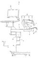
- a medical practice support system 1 shown in FIG. 1 is a system that supports a medical practice.
- the medical practice support system 1 in this embodiment is an example of a medical practice support apparatus.
- a dental implant is assumed as a medical practice.
- the dental implant is a dental operation in which an implant body is embedded in a jaw bone of a patient 100 (see FIG. 3), and a prosthesis is attached to the embedded implant body.
- a treatment position the position (part) of the jaw bone of the patient 100 in which the implant body is to be implanted.
- the medical practice support system 1 includes a surgical tool 2, an installation table 4, a position tracking device 12, a medical practice planning device 18, a display device 26, and an audio output device 28.
- the input device 30 and the guide robot 32 are provided.
- the surgical tool 2 is an instrument used for medical practice.
- the surgical tool 2 is attached to the tip of the guide robot 32.
- the surgical tool 2 in this embodiment includes a drill unit used for dentistry.
- This drill unit has various drill bits used for dentistry and a drive mechanism for driving the drill bits.
- the drill unit mentioned here includes a so-called dental handpiece.
- This dental handpiece is called a straight geared angle handpiece or a contra handpiece.
- the surgical tool 2 attached to the tip of the guide robot 32 supports the dental implant performed by the operator.
- the “dental implant support” mentioned here includes the movement of the surgical tool 2 to the treatment position, which is the site of the patient 100 in which the implant body is to be implanted.
- the movement of the surgical tool 2 includes the entry of the surgical tool 2 into the oral cavity of the patient 100 and the movement to an exchange position where the surgical tool 2 is exchanged.
- “dental implant support” mentioned here may include drilling the jawbone with a drill as the surgical tool 2.
- the installation table 4 is a mechanism on which the guide robot 32 is installed.
- the installation table 4 includes a top plate 6, a support unit 8, and an installation table drive mechanism 10 (see FIG. 2).
- the top plate 6 is a plate-like member to which the guide robot 32 is fixed.
- the support portion 8 is a support column that supports the top plate 6 horizontally.
- the installation table drive mechanism 10 includes a motor that drives the top plate 6 along the X-axis direction, the Y-axis direction, and the Z-axis direction.
- the installation table 4 is configured to freely move the guide robot 32 installed on the top plate 6 along the horizontal plane and the vertical direction.
- the position tracking device 12 is a device that specifies the relative positional relationship between the reference point defined in the guide robot 32 and the treatment position.
- the position tracking device 12 in this embodiment includes an arm 14 that is an articulated arm extended from an arm reference point, and an attachment 16 that is attached to the tip of the arm 14.
- the arm reference point mentioned here is a position where the extension of the arm 14 is started in the guide robot 32.
- the attachment 16 is attached to the affected part of the patient 100.
- a mouthpiece marked with a treatment position is used.
- the position tracking device 12 is a well-known tracking arm that specifies the position marked with the attachment 16 as a treatment position by the relative position from the arm reference point.
- the medical practice planning device 18 is a device that identifies a treatment position and creates a plan for medical treatment at the identified treatment position.
- the medical practice planning device 18 includes an information acquisition unit 20, a storage unit 22, and a control unit 24.
- the information acquisition unit 20 acquires information necessary for specifying the treatment position (hereinafter referred to as “position specifying information”).
- the information acquisition unit 20 acquires a plurality of tomographic images captured by a computed tomography (CT) apparatus as position specifying information.
- CT computed tomography
- the storage unit 22 is a known storage device that stores data and processing programs.
- the control unit 24 is a known control device having a known microcomputer including at least a ROM, a RAM, and a CPU, and executes processing according to a processing program stored in the storage unit 22.
- the storage unit 22 of the medical practice planning device 18 stores a processing program for the control unit 24 to execute a medical practice plan creation process for creating a “medical practice plan”.
- a “medical practice plan” is created according to the three-dimensional coordinate information of the jawbone of the patient 100 based on the position specifying information.
- the creation of this “medical practice plan” is carried out by specifying a position for implanting the implant body, an angle for implanting the implant body, and a depth for implanting the implant body in the planning coordinate system. Including that.
- the treatment position includes whether the jawbone into which the implant body is to be inserted is the maxilla or the mandible, and the position of the tooth in the jawbone.
- the “plan of medical practice” the timing when the surgical tool 2 enters the oral cavity of the patient 100 during the operation of the guide robot 32 when performing the medical practice to the treatment position, and the oral cavity of the patient 100 The approach angle of the surgical tool 2 may be included.
- the planning coordinate system referred to here is a coordinate system (for example, a coordinate system in a CT image) in “medical practice planning” planned by the medical practice planning device 18.
- plan of medical practice is referred to as medical practice necessary information.
- method of creating the “medical practice plan” is well known, detailed description thereof is omitted here.
- the display device 26 is a known device (for example, a liquid crystal display) that displays an image.
- the sound output device 28 is a known device (for example, a speaker) that outputs sound.
- the input device 30 is a well-known device that accepts input of information.
- the input device 30 includes various input devices such as a keyboard, a pointing device, and a switch.
- the pointing device here includes a known mechanism such as a touch pad or a touch panel.
- the guide robot 32 is a well-known vertical articulated robot including an articulated arm 34 and a robot control unit 50.
- the multi-joint arm 34 is located at the distal end of the base part 36 fixed to the installation base 4, the upper arm part 38 and the forearm part 40 that form an arm extending from the base part 36, and the forearm part 40. Is provided with a hand attachment portion 42 to which is attached.
- Each joint section includes a robot drive device 44 and a sensing device 46.
- the robot drive device 44 is a device that drives the articulated arm 34.
- a motor that drives each joint is used.
- the sensing device 46 detects the coordinates of the tip of the multi-joint arm 34 (and consequently the surgical tool 2).
- a rotary encoder that detects the rotation angle of each robot drive device 44 may be used.
- the articulated arm 34 is a known arm having a plurality of movable parts in a real space three-dimensional coordinate system (X, Y, Z coordinate system).
- the surgical tool 2 is attached to the tip of the multi-joint arm 34 (that is, the hand attachment portion 42).
- the robot control unit 50 drives the robot drive device 44 of the guide robot 32 according to the result of sensing by the sensing device 46.
- the robot control unit 50 includes a control unit 52 and a storage unit 54.
- the control unit 52 is a known control device having a known microcomputer provided with at least a ROM, a RAM, and a CPU.
- the storage unit 54 is a known device that stores information and data.
- the storage unit 54 stores a processing program for the robot control unit 50 to execute a medical practice support process in which the medical practice performed by the surgeon is supported by the medical practice support system 1. ⁇ Medical practice support processing> Next, a medical practice support process executed by the robot controller 50 will be described.
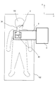
- the medical practice support system 1 is installed at a predetermined apparatus installation location 80 as shown in FIG. 3 so that the position tracking device 12 can track the implantation position of the patient 100. It is started with.
- a position where the top plate 6 of the installation table 4 covers at least a part of the chest of the patient 100 lying on the bed (operating table) 102 can be considered.
- the control unit 52 of the robot control unit 50 acquires medical practice necessary information from the medical practice planning device 18 as shown in FIG. 4 (S110).
- the control unit 52 acquires the relative position from the arm reference point of the marked portion on the attachment 16 of the position tracking device 12 from the position tracking device 12 (S120). Subsequently, in the medical practice support process, the control unit 52 registers the initial position of the treatment position of the patient 100 in the real space three-dimensional coordinate system based on the relative position of the marked portion of the attachment 16 acquired in S120. (S130). Registration of the initial position of the treatment position in S130 may be executed according to a well-known registration. The registration is a process of converting and registering the treatment position in the planning coordinate system specified by the medical practice planning device 18 into the treatment position in the three-dimensional coordinate system in the real space.
- the coordinates of the marked part of the attachment 16 in the planning coordinate system are calculated according to the following equation (1).
- TRAK T TRAKtip in the equation (1) is the position of the tip of the arm 14 in the position tracking device 12 in the real space three-dimensional coordinate system.
- the code “ TRAK T A ′ ” is the position of the attachment 16 in the position tracking device 12 in the real space three-dimensional coordinate system.
- the symbol “ A ′ T A ” is a value for correcting an attachment error of the attachment 16.
- the coordinates of the marked portion of the attachment 16 in the three-dimensional coordinate system in the real space is calculated according to the following equation (2).
- CT T IMP the code “CT T IMP ” in the equation (2) is a treatment position in the planning coordinate system.
- This registration makes it possible to track the relative position from the arm reference point of the marked portion of the attachment 16 obtained by the position tracking device 12 as the treatment position in the real space three-dimensional coordinate system.
- the calibration referred to here is a process of arranging the relative positional relationship between the tool tip position and the treatment position in a common coordinate system.
- the common coordinate system here is a three-dimensional coordinate system in real space, for example, a robot coordinate system in the guide robot 32.
- the tool tip position referred to here is a tip position representing the tip portion of the surgical tool 2, for example, the position of the tip portion of the drill bit.
- This tool tip position is an example of a tip position representing the position of the tip portion of the articulated arm.
- the control unit 52 derives an arm operation mode representing an operation mode of the multi-joint arm 34 based on the medical action necessity information acquired in S110 (S140).
- the arm operation mode referred to here includes the trajectory of the articulated arm 34 of the guide robot 32 in medical practice (hereinafter referred to as “arm trajectory”).
- the guide robot 32 (multi-joint arm) that moves the surgical tool 2 during the medical action to the treatment position according to the “medical action plan” planned by the medical action planning device 18.
- 34 is derived as an arm trajectory. This arm trajectory is normally determined so that a singular point that makes the articulated arm 34 uncontrollable does not occur. Since the derivation of the arm trajectory is performed using a well-known method in the vertical articulated robot, detailed description thereof is omitted here.
- the control unit 52 sets a movable prohibited area using the treatment position registered in S130 as a base point.
- the movement prohibition area referred to here is an area where the tip portion of the articulated arm 34 is prohibited from moving. This movable prohibition area is set outside the movable area, for example, at the periphery of the movable area.
- region said here is an area
- “setting the movement prohibited area based on the treatment position as a base point” means that the movement prohibited area is set so that the relative positional relationship between the reference coordinates and the treatment position in the movement prohibited area satisfies a predetermined condition. Is to set.
- the predetermined condition may be, for example, that the center of gravity of the movable area on the XY plane passing through the treatment position matches the treatment position.
- the control unit 52 of the robot control unit 50 outputs the movement prohibited area set in S150 to the display device 26 (S160).
- the display device 26 displays the movable prohibited area.
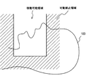
- the display device 26 displays the movable prohibited area so as to be superimposed on an image showing the periphery of the treatment position of the patient 100.
- the movable prohibited area displayed on the display device 26 is displayed in a manner distinguishable from the movable area.
- 5A is a view of the movable area and the movable prohibited area as viewed from the side
- FIG. 5B is a view of the movable area and the movable prohibited area as viewed from above.
- control unit 52 determines whether or not an instruction to change the prohibited area has been received via the input device 30 (S170).
- the instruction to change the movement prohibition area may be received by correcting the movement prohibition area displayed on the display device 26 via the input device 30.
- control unit 52 changes the prohibited movement area in accordance with the received change instruction (S180).
- the change of the movement prohibited area referred to here is, for example, changing the position of the movement prohibited area or changing the size of the movement prohibited area.
- control unit 52 returns the medical practice support process to S160.
- control unit 52 causes the display device 26 to display the changed movable prohibited area.
- control unit 52 shifts the medical practice support process to S190.
- the control unit 52 operates the guide robot 32 so that the surgical tool 2 moves according to the arm trajectory derived in S140.
- the control unit 52 specifies the tool tip position (S200).
- S200 the tool tip position
- a known method of specifying according to the relative positional relationship with the arm reference point of the multi-joint arm 34 can be considered.
- control unit 52 performs the treatment in the three-dimensional coordinate system in the real space based on the relative position from the arm reference point of the marked portion in the attachment 16 obtained by the position tracking device 12.
- the position is specified (S210). That is, in S210 that is repeatedly executed in the medical practice support process, the treatment position is sequentially specified along the time axis.
- control unit 52 updates the movement prohibition area in the three-dimensional coordinate system of the real space based on the treatment position specified in S210 (S220). Specifically, in S220, even if the treatment position in the three-dimensional coordinates of the real space changes, the control unit 52 sets the actual movement prohibited area so that the movement prohibited area is set based on the changed treatment position. Update 3D coordinates in space.
- the control unit 52 determines whether or not the tool tip position calculated in S190 is within the movable prohibited area updated in S220 (S230). As a result of this determination, if the tool tip position is within the movement prohibited region (S230: YES), the control unit 52 shifts the medical practice support process to S290 described later in detail.
- the control unit 52 calculates a boundary distance representing the distance between the tool tip position specified in S190 and the region boundary.
- the region boundary referred to here is a boundary between the movable region and the movable prohibited region.
- the control unit 52 calculates the distance from the tool tip position to the region boundary existing at the closest position as the boundary distance.
- control unit 52 determines whether or not the boundary distance calculated in S240 is equal to or less than a predetermined threshold (S250). As a result of the determination in S250, if the boundary distance is equal to or smaller than the threshold (S250: YES), the control unit 52 shifts the medical practice support process to S280 described later in detail.
- control unit 52 determines whether or not the tool tip position specified in S190 matches the treatment position specified in S210. Is determined (S260).
- control unit 52 If the result of determination in S260 is that the tool tip position and the treatment position do not match (S260: NO), the control unit 52 returns the medical practice support processing to S190.
- the control unit 52 receives an input of a drill command that is a command for driving the drill (S270).
- the control unit 52 to which the drill command is input rotates the drill bit of the surgical tool 2. Then, the surgeon performs perforation to the jawbone using the surgical tool 2.
- control unit 52 returns the medical practice support process to S190.
- control unit 52 performs notification control for notifying that the tool tip position is approaching the region boundary. Execute.
- control unit 52 may output a signal indicating that the tool tip position is approaching the region boundary to the display device 26 and the audio output device 28.
- the display device 26 that has acquired the signal displays that the tool tip position is approaching the region boundary.
- the voice output device 28 that has acquired the signal outputs by voice that the tool tip position is approaching the region boundary.
- the operation resistance of the articulated arm 34 is increased as the distance between the tool tip position and the region boundary is shorter.
- control unit 52 returns the medical practice support process to S190.
- control unit 52 executes safety control for improving the safety of the medical practice.
- the safety control it is conceivable to stop the operation of the guide robot 32 so as to stop the movement of the distal end portion of the articulated arm 34 and eventually the surgical tool 2.
- the control unit 52 may output a signal indicating that the tool tip position is outside the movement prohibited region to the display device 26 and the audio output device 28.
- the display device 26 that has acquired the signal displays that the tool tip position is outside the movement prohibited region
- the audio output device 28 that has acquired the signal indicates that the tool tip position is outside the movement prohibited region. May be output by voice.
- control unit 52 ends the medical practice support process.
- safety control can be executed when the tool tip position moves to the movement prohibited area. This safety control is control that improves the safety of medical practice.
- S280 of the medical practice support process when notification control is executed when the tool tip position approaches the region boundary, the user (for example, a surgeon) of the medical practice support system 1 can move the tool tip within the movable range. It can be recognized that the tool tip position is approaching the movement prohibited area before the position reaches the movement prohibited area.
- the guide robot 32 only assists the movement of the articulated arm 34, and the operator often operates the articulated arm 34. From this, in the medical practice support process, the following effects can be obtained when executing the notification control to increase the operation resistance of the articulated arm 34 as the tool tip position is closer to the region boundary.
- the effect is that the operator can recognize that the tool tip position is approaching the region boundary while maintaining the operator's concentration on the medical practice, and the operator is approaching the region boundary. That is, it can be recognized without a sense of incongruity during the execution of medical practice.
- the movable prohibited area is updated according to the change of the treatment position.
- the user of the medical practice support system 1 can edit the prohibited area. For this reason, the user of the medical practice support system 1 can set a movable prohibition area that is easy to use when performing a medical practice, and can perform the medical practice more smoothly.
- this indication is not limited to the above-mentioned embodiment, and can be carried out in various modes in the range which does not deviate from the gist of this indication.
- the positional relationship between the tool tip position and the region boundary is defined as a predetermined condition that indicates that the tool tip position is approaching the region boundary. Whether the boundary distance is satisfied or not is determined by determining whether the boundary distance is less than or equal to the threshold value. However, whether the positional relationship between the tool tip position and the area boundary satisfies the specified condition.
- the determination method is not limited to this. For example, whether or not the positional relationship between the tool tip position and the region boundary satisfies a prescribed condition is determined based on the tool tip position specified along the time axis at a prescribed time specified in advance.
- the distal end portion of the surgical tool 2 that is, the distal end portion of the drill bit is used as the tool distal end position, but the distal end position is not limited to this.
- the tip position in the present disclosure may be the position of the tip portion of the articulated arm 34 itself, or may be the position of a specific part in the surgical tool 2.
- the position tracking device 12 is configured by a known tracking arm, but the position tracking device 12 is not limited to this. That is, for example, the position tracking device 12 may be a device that irradiates an exploration wave such as an infrared ray with improved directivity and tracks changes in the implantation position, and can specify the coordinates of other implantation positions. It may be a simple device. In the former case, the mechanism for irradiating the exploration wave may be arranged on the space where the medical practice support system 1 is arranged, or may be arranged at the treatment site of the patient 100.
- an exploration wave such as an infrared ray with improved directivity and tracks changes in the implantation position
- the mechanism for irradiating the exploration wave may be arranged on the space where the medical practice support system 1 is arranged, or may be arranged at the treatment site of the patient 100.
- the position tracking device 12 may be any device as long as it can identify the relative positional relationship between the reference point defined in the guide robot 32 and the treatment position.
- the information acquisition unit 20 of the medical practice planning apparatus 18 in the above embodiment has acquired the position specifying information from the computed tomography apparatus
- the information acquisition unit 20 of the medical practice planning apparatus 18 has the position from other apparatuses. Specific information may be acquired.
- a dental implant is assumed as the medical action supported by the medical action support system 1, but the medical action supported by the medical action support system 1 is not limited to a dental implant.
- the medical practice supported by the medical practice support system may be surgery, internal medicine, dental care other than a dental implant, or other medical practice. May be.
- the treatment position is not limited to the position (part) of the patient's jawbone in which the implant body is to be implanted.
- the part of the patient 100 requiring surgery, the part of the patient 100 requiring medical treatment, and the dental It may be the part of the patient 100 in need of medical care.
- the surgical tool 2 attached to the tip of the guide robot 32 is not limited to a drill unit used for dentistry, and may be a tool used for various medical practices.
- the tool used for various medical activities may be, for example, a surgical instrument such as a scalpel or forceps, or other medical instrument.
- the medical practice support system 1 may include a stop switch that stops the medical practice support by the guide robot 32 and a switch that accepts whether the medical assistance by the guide robot 32 is supported.
- each section is expressed as S100, for example.
- each section can be divided into a plurality of subsections, while a plurality of sections can be combined into one section.
- each section configured in this manner can be referred to as a device, module, or means.
Landscapes
- Engineering & Computer Science (AREA)
- Health & Medical Sciences (AREA)
- Life Sciences & Earth Sciences (AREA)
- Robotics (AREA)
- Surgery (AREA)
- Medical Informatics (AREA)
- Biomedical Technology (AREA)
- Heart & Thoracic Surgery (AREA)
- Nuclear Medicine, Radiotherapy & Molecular Imaging (AREA)
- Molecular Biology (AREA)
- Animal Behavior & Ethology (AREA)
- General Health & Medical Sciences (AREA)
- Public Health (AREA)
- Veterinary Medicine (AREA)
- Mechanical Engineering (AREA)
- Manipulator (AREA)
Abstract
A medical procedure assist device comprises an articulated robot that has an articulated arm with a plurality of arms connected by joints, a position identifying unit (S130, S210), a region setting unit (S150), a tip position identifying unit (S190), and a controlling unit (S290). The position identifying unit (S130, S210) identifies a treatment site representing the location of a site on a patient where the medical procedure is to be performed. The region setting unit (S150) sets, using the treatment site identified by the position identifying unit as a reference point, a movement prohibited region that is outside of a movement permitted region in which the tip of the articulated arm can move during implementation of the medical procedure and that represents a region into which the tip of the articulated arm is prohibited from entering. The tip position identifying unit (S190) identifies the tip position representing the position of the tip of the articulated arm. The controlling unit (S290) executes safety controls to improve the safety of the medical procedure when the tip position identified by the tip position identifying unit (S190) moves into the movement prohibited region set by the region setting unit (S150).
Description
本出願は、2015年6月26日に出願された日本出願番号2015-128885号に基づくもので、ここにその記載内容を援用する。
This application is based on Japanese Application No. 2015-128885 filed on June 26, 2015, the contents of which are incorporated herein by reference.
本開示は、医療行為を支援する医療行為支援装置に関する。
This disclosure relates to a medical practice support apparatus that supports medical practice.
従来、医療行為を支援する医療行為支援装置が知られている(例えば、特許文献1参照)。
Conventionally, medical practice support devices that support medical practice are known (for example, see Patent Document 1).
この種の医療行為支援装置の中には、医療行為の1つである歯科インプラントを支援する医療行為支援装置が存在する。この医療行為支援装置は、歯科医療に用いるドリルビットを有したドリルユニットと、そのドリルビットの先端を術者が望む位置へと移動させる多関節ロボットとを備えている。
In this type of medical practice support device, there is a medical practice support device that supports dental implants, which is one type of medical practice. This medical practice support apparatus includes a drill unit having a drill bit used for dentistry, and an articulated robot that moves the tip of the drill bit to a position desired by an operator.
医療行為支援装置においては、医療行為における安全性を担保するために、ドリルビットの先端が移動可能な範囲(以下、「移動可能範囲」と称す)が規定されている。そして、ドリルビットの先端を術者が望む位置へと移動させる際に、移動可能範囲内に予め規定された経路に沿って、ドリルビットの先端が移動するように多関節ロボットが動作する。
In the medical practice support device, a range in which the tip of the drill bit can be moved (hereinafter referred to as “movable range”) is defined in order to ensure safety in the medical practice. Then, when the tip of the drill bit is moved to a position desired by the operator, the articulated robot operates so that the tip of the drill bit moves along a path that is defined in advance within the movable range.
ところで、多関節ロボットは、外乱などのノイズによって誤動作する可能性がある。そして、多関節ロボットが誤動作すると、ドリルビットの先端が移動可能範囲の外に達し、安全性を低下させるおそれがある。
By the way, an articulated robot may malfunction due to noise such as disturbance. If the multi-joint robot malfunctions, the tip of the drill bit reaches the outside of the movable range, which may reduce safety.
つまり、医療行為支援装置においては、多関節ロボットが誤動作したとしても、高い安全性を担保することが求められている。
That is, in the medical practice support apparatus, even if the articulated robot malfunctions, it is required to ensure high safety.
そこで、本開示は、多関節ロボットが誤動作したとしても、高い安全性を担保することができる医療行為支援装置を提供することを目的とする。
Therefore, an object of the present disclosure is to provide a medical practice support apparatus that can ensure high safety even if an articulated robot malfunctions.
本開示の一態様によれば、医療行為支援装置は、多関節ロボットと、位置特定部と、領域設定部と、先端位置特定部と、制御部とを備える。
According to one aspect of the present disclosure, the medical practice support apparatus includes an articulated robot, a position specifying unit, a region setting unit, a tip position specifying unit, and a control unit.
多関節ロボットは、複数のアームが関節によって接続された多関節アームを有する。位置特定部は、医療行為を受ける患者の部位の位置を表す施術位置を特定する。
The multi-joint robot has a multi-joint arm in which a plurality of arms are connected by joints. The position specifying unit specifies a treatment position indicating the position of a part of a patient who receives a medical practice.
領域設定部は、医療行為を実施する際の多関節アームの先端部分が移動可能な領域である移動可能領域の外側に多関節アームの先端部分が移動することを禁止する領域を表す可動禁止領域を、位置特定部で特定した施術位置を基点として設定する。
The region setting unit is a movable prohibition region that represents a region in which the tip portion of the articulated arm is prohibited from moving outside the movable region, which is a region in which the tip portion of the articulated arm is movable when performing a medical practice. Is set with the treatment position specified by the position specifying unit as a base point.
先端位置特定部は、多関節アームの先端部分の位置を表す先端位置を特定する。制御部は、先端位置特定部で特定した先端位置が、領域設定部で設定された可動禁止領域へと移動すると、医療行為の安全性を向上させる安全制御を実行する。
The tip position specifying unit specifies the tip position representing the position of the tip portion of the articulated arm. When the tip position specified by the tip position specifying unit moves to the movement prohibited region set by the region setting unit, the control unit executes safety control that improves the safety of medical practice.
このような医療行為支援装置によれば、可動禁止領域へと先端位置が移動した場合に安全制御を実行できる。この安全制御は、医療行為の安全性を向上させる制御である。
According to such a medical practice support device, safety control can be executed when the tip position moves to the movable prohibited area. This safety control is control that improves the safety of medical practice.
したがって、医療行為支援装置によれば、多関節ロボットが誤動作して、可動禁止領域へと先端位置が移動するようなことがあっても、高い安全性を担保できる。
Therefore, according to the medical practice support apparatus, even if the articulated robot malfunctions and the tip position moves to the movable prohibited area, high safety can be ensured.
本開示についての上記目的およびその他の目的、特徴や利点は、添付の図面を参照しながら下記の詳細な記述により、より明確になる。
医療行為支援装置の概略構成を説明する説明図である。
医療行為支援装置の制御系を説明するブロック図である。
医療行為支援装置の概要を説明する説明図である。
医療行為支援処理の処理手順を説明するフローチャートである。
医療行為支援処理の処理内容を説明する説明図であり、移動可能領域および可動禁止領域を側方視した図である。
医療行為支援処理の処理内容を説明する説明図であり、移動可能領域および可動禁止領域を上方視した図である。
The above and other objects, features, and advantages of the present disclosure will become more apparent from the following detailed description with reference to the accompanying drawings.
It is explanatory drawing explaining schematic structure of a medical practice assistance apparatus. It is a block diagram explaining the control system of a medical practice assistance apparatus. It is explanatory drawing explaining the outline | summary of a medical practice assistance apparatus. It is a flowchart explaining the process sequence of a medical practice assistance process. It is explanatory drawing explaining the processing content of a medical practice assistance process, and is the figure which looked at the movable area | region and the movement prohibition area | region laterally. It is explanatory drawing explaining the processing content of a medical practice assistance process, and is the figure which looked up at the movable area | region and the movement prohibition area | region.
以下に本開示の実施形態を図面と共に説明する。
<医療行為支援システム>
図1に示す医療行為支援システム1は、医療行為を支援するシステムである。本実施形態における医療行為支援システム1は、医療行為支援装置の一例である。 Hereinafter, embodiments of the present disclosure will be described with reference to the drawings.
<Medical practice support system>
A medical practice support system 1 shown in FIG. 1 is a system that supports a medical practice. The medical practice support system 1 in this embodiment is an example of a medical practice support apparatus.
本実施形態においては、医療行為として、歯科インプラントを想定する。歯科インプラントは、患者100(図3参照)の顎骨にインプラント体を埋め込み、その埋め込まれたインプラント体に補綴物を装着する歯科手術である。以下では、インプラント体を埋入する患者100の顎骨の位置(部位)を施術位置と称す。
In this embodiment, a dental implant is assumed as a medical practice. The dental implant is a dental operation in which an implant body is embedded in a jaw bone of a patient 100 (see FIG. 3), and a prosthesis is attached to the embedded implant body. Hereinafter, the position (part) of the jaw bone of the patient 100 in which the implant body is to be implanted is referred to as a treatment position.
図1,図2に示すように、医療行為支援システム1は、手術ツール2と、設置台4と、位置追跡装置12と、医療行為計画装置18と、表示装置26と、音声出力装置28と、入力装置30と、ガイドロボット32とを備えている。
As shown in FIGS. 1 and 2, the medical practice support system 1 includes a surgical tool 2, an installation table 4, a position tracking device 12, a medical practice planning device 18, a display device 26, and an audio output device 28. The input device 30 and the guide robot 32 are provided.
手術ツール2は、医療行為に用いる器具である。この手術ツール2は、ガイドロボット32の先端に取り付けられる。
The surgical tool 2 is an instrument used for medical practice. The surgical tool 2 is attached to the tip of the guide robot 32.
本実施形態における手術ツール2には、歯科医療に用いるドリルユニットを含む。このドリルユニットは、歯科医療に用いる各種のドリルビットと、そのドリルビットを駆動する駆動機構とを有している。なお、ここで言うドリルユニットには、いわゆる歯科用ハンドピースを含む。この歯科用ハンドピースとは、ストレート・ギアードアングルハンドピースやコントラハンドピースと称されるものである。
The surgical tool 2 in this embodiment includes a drill unit used for dentistry. This drill unit has various drill bits used for dentistry and a drive mechanism for driving the drill bits. The drill unit mentioned here includes a so-called dental handpiece. This dental handpiece is called a straight geared angle handpiece or a contra handpiece.
医療行為支援システム1では、ガイドロボット32の先端に取り付けられた手術ツール2により、術者が実施する歯科インプラントを支援する。ここで言う「歯科インプラントの支援」には、インプラント体を埋入する患者100の部位である施術位置への手術ツール2の移動が含まれる。この手術ツール2の移動には、患者100の口腔内への手術ツール2の進入や、手術ツール2を交換する交換位置への移動が含まれる。
In the medical practice support system 1, the surgical tool 2 attached to the tip of the guide robot 32 supports the dental implant performed by the operator. The “dental implant support” mentioned here includes the movement of the surgical tool 2 to the treatment position, which is the site of the patient 100 in which the implant body is to be implanted. The movement of the surgical tool 2 includes the entry of the surgical tool 2 into the oral cavity of the patient 100 and the movement to an exchange position where the surgical tool 2 is exchanged.
さらに、ここで言う「歯科インプラントの支援」には、手術ツール2としてのドリルによる顎骨への穿孔を含んでもよい。
Furthermore, “dental implant support” mentioned here may include drilling the jawbone with a drill as the surgical tool 2.
設置台4は、ガイドロボット32が設置される機構である。この設置台4は、天板6と、支持部8と、設置台駆動機構10(図2参照)とを備えている。
The installation table 4 is a mechanism on which the guide robot 32 is installed. The installation table 4 includes a top plate 6, a support unit 8, and an installation table drive mechanism 10 (see FIG. 2).
天板6は、ガイドロボット32が固定される板状の部材である。支持部8は、天板6を水平に支持する支柱である。設置台駆動機構10は、天板6をX軸方向,Y軸方向,Z軸方向のそれぞれの方向に沿って駆動させるモータを有している。
The top plate 6 is a plate-like member to which the guide robot 32 is fixed. The support portion 8 is a support column that supports the top plate 6 horizontally. The installation table drive mechanism 10 includes a motor that drives the top plate 6 along the X-axis direction, the Y-axis direction, and the Z-axis direction.
すなわち、設置台4は、天板6に設置されたガイドロボット32を、水平面及び垂直方向に沿って自在に移動するように構成されている。
That is, the installation table 4 is configured to freely move the guide robot 32 installed on the top plate 6 along the horizontal plane and the vertical direction.
位置追跡装置12は、ガイドロボット32に規定された基準点と、施術位置との相対的な位置関係を特定する装置である。
The position tracking device 12 is a device that specifies the relative positional relationship between the reference point defined in the guide robot 32 and the treatment position.
本実施形態における位置追跡装置12は、アーム基準点から延出された多関節アームであるアーム14と、アーム14の先端に取り付けられるアタッチメント16とを有する。ここで言うアーム基準点とは、ガイドロボット32においてアーム14の延出が開始される位置である。
The position tracking device 12 in this embodiment includes an arm 14 that is an articulated arm extended from an arm reference point, and an attachment 16 that is attached to the tip of the arm 14. The arm reference point mentioned here is a position where the extension of the arm 14 is started in the guide robot 32.
アタッチメント16は、患者100の患部に取り付けられる。本実施形態におけるアタッチメント16として、施術位置がマーキングされたマウスピースを用いる。
The attachment 16 is attached to the affected part of the patient 100. As the attachment 16 in the present embodiment, a mouthpiece marked with a treatment position is used.
すなわち、位置追跡装置12は、アタッチメント16のマーキングされた位置を施術位置として、アーム基準点からの相対位置によって特定する周知のトラッキングアームである。
That is, the position tracking device 12 is a well-known tracking arm that specifies the position marked with the attachment 16 as a treatment position by the relative position from the arm reference point.
医療行為計画装置18は、施術位置を特定して、その特定した施術位置への医療行為の計画を作成する装置である。この医療行為計画装置18は、情報取得部20と、記憶部22と、制御部24とを備えている。情報取得部20は、施術位置の特定に必要な情報(以下、「位置特定情報」と称す)を取得する。
The medical practice planning device 18 is a device that identifies a treatment position and creates a plan for medical treatment at the identified treatment position. The medical practice planning device 18 includes an information acquisition unit 20, a storage unit 22, and a control unit 24. The information acquisition unit 20 acquires information necessary for specifying the treatment position (hereinafter referred to as “position specifying information”).
本実施形態における情報取得部20は、コンピュータ断層撮影(CT:Computed Tomography)装置によって撮影した複数の断層画像を位置特定情報として取得する。
The information acquisition unit 20 according to the present embodiment acquires a plurality of tomographic images captured by a computed tomography (CT) apparatus as position specifying information.
記憶部22は、データや処理プログラムを記憶する周知の記憶装置である。
The storage unit 22 is a known storage device that stores data and processing programs.
制御部24は、少なくともROM,RAM,CPUを備えた周知のマイクロコンピュータを有した周知の制御装置であり、記憶部22に記憶された処理プログラムに従って処理を実行する。
The control unit 24 is a known control device having a known microcomputer including at least a ROM, a RAM, and a CPU, and executes processing according to a processing program stored in the storage unit 22.
なお、医療行為計画装置18の記憶部22には、「医療行為の計画」を作成する医療行為計画作成処理を制御部24が実行するための処理プログラムが格納されている。
Note that the storage unit 22 of the medical practice planning device 18 stores a processing program for the control unit 24 to execute a medical practice plan creation process for creating a “medical practice plan”.
この医療行為計画作成処理では、位置特定情報に基づく患者100の顎骨の3次元座標情報に従って、「医療行為の計画」を作成する。この「医療行為の計画」の作成は、インプラント体を埋入する施術位置の特定、インプラント体を埋入する角度の特定、インプラント体を埋入する深さの特定を、プランニング座標系において実施することを含む。なお、施術位置には、インプラント体を埋入する顎骨が上顎骨であるか下顎骨であるか、その顎骨における歯の位置を含む。「医療行為の計画」には、施術位置へ医療行為を実施する際のガイドロボット32の動作時における、患者100の口腔内への手術ツール2を進入させるタイミングや、その患者100の口腔内への手術ツール2の進入角度を含んでもよい。
In this medical practice plan creation process, a “medical practice plan” is created according to the three-dimensional coordinate information of the jawbone of the patient 100 based on the position specifying information. The creation of this “medical practice plan” is carried out by specifying a position for implanting the implant body, an angle for implanting the implant body, and a depth for implanting the implant body in the planning coordinate system. Including that. The treatment position includes whether the jawbone into which the implant body is to be inserted is the maxilla or the mandible, and the position of the tooth in the jawbone. In the “plan of medical practice”, the timing when the surgical tool 2 enters the oral cavity of the patient 100 during the operation of the guide robot 32 when performing the medical practice to the treatment position, and the oral cavity of the patient 100 The approach angle of the surgical tool 2 may be included.
なお、ここで言うプランニング座標系とは、医療行為計画装置18にて計画される「医療行為の計画」における座標系(例えば、CT画像における座標系)である。
The planning coordinate system referred to here is a coordinate system (for example, a coordinate system in a CT image) in “medical practice planning” planned by the medical practice planning device 18.
以下、「医療行為の計画」を、医療行為必要情報と称す。なお、「医療行為の計画」を作成する方法は、周知であるため、ここでの詳しい説明は省略する。
Hereinafter, “plan of medical practice” is referred to as medical practice necessary information. In addition, since the method of creating the “medical practice plan” is well known, detailed description thereof is omitted here.
表示装置26は、画像を表示する周知の装置(例えば、液晶ディスプレイ)である。音声出力装置28は、音声を出力する周知の装置(例えば、スピーカ)である。
The display device 26 is a known device (for example, a liquid crystal display) that displays an image. The sound output device 28 is a known device (for example, a speaker) that outputs sound.
また、入力装置30は、情報の入力を受け付ける周知の装置である。この入力装置30には、キーボードやポインティングデバイス、スイッチなどの各種入力機器を含む。ここで言うポインティングデバイスには、タッチパッドやタッチパネルなどの周知の機構を含む。
<ガイドロボット>
ガイドロボット32は、多関節アーム34と、ロボット制御部50とを備えた、周知の垂直多関節ロボットである。 Theinput device 30 is a well-known device that accepts input of information. The input device 30 includes various input devices such as a keyboard, a pointing device, and a switch. The pointing device here includes a known mechanism such as a touch pad or a touch panel.
<Guide robot>
Theguide robot 32 is a well-known vertical articulated robot including an articulated arm 34 and a robot control unit 50.
<ガイドロボット>
ガイドロボット32は、多関節アーム34と、ロボット制御部50とを備えた、周知の垂直多関節ロボットである。 The
<Guide robot>
The
多関節アーム34は、設置台4に固定されるベース部36と、ベース部36から延出するアームを形成する上腕部38及び前腕部40と、前腕部40の先端に位置し、手術ツール2が取り付けられるハンド取付部42とを備えている。
The multi-joint arm 34 is located at the distal end of the base part 36 fixed to the installation base 4, the upper arm part 38 and the forearm part 40 that form an arm extending from the base part 36, and the forearm part 40. Is provided with a hand attachment portion 42 to which is attached.
多関節アーム34を構成するベース部36と上腕部38と前腕部40とハンド取付部42とは、それぞれ、関節部を介して接続されている。この関節部それぞれは、ロボット駆動装置44と、センシング装置46とを備えている。
The base part 36, the upper arm part 38, the forearm part 40, and the hand attachment part 42 constituting the multi-joint arm 34 are connected via joint parts. Each joint section includes a robot drive device 44 and a sensing device 46.
ロボット駆動装置44は、多関節アーム34を駆動する装置である。このロボット駆動装置44として、各関節部を駆動するモータを用いる。センシング装置46は、多関節アーム34の先端(ひいては、手術ツール2)の座標を検出するものである。このセンシング装置46として、例えば、ロボット駆動装置44それぞれの回転角度を検出するロータリーエンコーダを用いてもよい。
The robot drive device 44 is a device that drives the articulated arm 34. As the robot drive device 44, a motor that drives each joint is used. The sensing device 46 detects the coordinates of the tip of the multi-joint arm 34 (and consequently the surgical tool 2). As the sensing device 46, for example, a rotary encoder that detects the rotation angle of each robot drive device 44 may be used.
すなわち、多関節アーム34は、実空間の三次元座標系(X,Y,Z座標系)において、複数の可動部を有する周知のアームである。この多関節アーム34の先端(即ち、ハンド取付部42)には、手術ツール2が取り付けられる。
That is, the articulated arm 34 is a known arm having a plurality of movable parts in a real space three-dimensional coordinate system (X, Y, Z coordinate system). The surgical tool 2 is attached to the tip of the multi-joint arm 34 (that is, the hand attachment portion 42).
ロボット制御部50は、センシング装置46でのセンシングの結果に従って、ガイドロボット32のロボット駆動装置44を駆動する。このロボット制御部50は、制御部52と、記憶部54とを備えている。
The robot control unit 50 drives the robot drive device 44 of the guide robot 32 according to the result of sensing by the sensing device 46. The robot control unit 50 includes a control unit 52 and a storage unit 54.
制御部52は、少なくともROM,RAM,CPUを備えた周知のマイクロコンピュータを有した周知の制御装置である。記憶部54は、情報やデータを記憶する周知の装置である。
The control unit 52 is a known control device having a known microcomputer provided with at least a ROM, a RAM, and a CPU. The storage unit 54 is a known device that stores information and data.
記憶部54には、術者が実施する医療行為を医療行為支援システム1にて支援する医療行為支援処理をロボット制御部50が実行するための処理プログラムが格納されている。
<医療行為支援処理>
次に、ロボット制御部50が実行する医療行為支援処理について説明する。 Thestorage unit 54 stores a processing program for the robot control unit 50 to execute a medical practice support process in which the medical practice performed by the surgeon is supported by the medical practice support system 1.
<Medical practice support processing>
Next, a medical practice support process executed by therobot controller 50 will be described.
<医療行為支援処理>
次に、ロボット制御部50が実行する医療行為支援処理について説明する。 The
<Medical practice support processing>
Next, a medical practice support process executed by the
医療行為支援処理は、図3に示すような予め規定された装置設置場所80に医療行為支援システム1を設置し、位置追跡装置12にて患者100の埋入位置を追跡可能な状態とした上で起動される。なお、装置設置場所80の一例として、ベッド(手術台)102に横たわる患者100の胸部の少なくとも一部分を、設置台4の天板6が覆う位置が考えられる。
In the medical practice support process, the medical practice support system 1 is installed at a predetermined apparatus installation location 80 as shown in FIG. 3 so that the position tracking device 12 can track the implantation position of the patient 100. It is started with. As an example of the apparatus installation location 80, a position where the top plate 6 of the installation table 4 covers at least a part of the chest of the patient 100 lying on the bed (operating table) 102 can be considered.
そして、医療行為支援処理が起動されると、ロボット制御部50の制御部52は、図4に示すように、医療行為計画装置18から医療行為必要情報を取得する(S110)。
Then, when the medical practice support process is activated, the control unit 52 of the robot control unit 50 acquires medical practice necessary information from the medical practice planning device 18 as shown in FIG. 4 (S110).
そして、医療行為支援処理では、制御部52は、位置追跡装置12のアタッチメント16におけるマーキングされた箇所のアーム基準点からの相対位置を位置追跡装置12から取得する(S120)。続いて、医療行為支援処理では、制御部52は、S120で取得したアタッチメント16のマーキングされた箇所の相対位置に基づいて、実空間の3次元座標系における患者100の施術位置の初期位置を登録する(S130)。このS130における施術位置の初期位置の登録は、周知のレジストレーションに従って実行すればよい。レジストレーションは、医療行為計画装置18にて特定した、プランニング座標系における施術位置を、実空間の3次元座標系における施術位置へと変換して登録する処理である。
In the medical practice support process, the control unit 52 acquires the relative position from the arm reference point of the marked portion on the attachment 16 of the position tracking device 12 from the position tracking device 12 (S120). Subsequently, in the medical practice support process, the control unit 52 registers the initial position of the treatment position of the patient 100 in the real space three-dimensional coordinate system based on the relative position of the marked portion of the attachment 16 acquired in S120. (S130). Registration of the initial position of the treatment position in S130 may be executed according to a well-known registration. The registration is a process of converting and registering the treatment position in the planning coordinate system specified by the medical practice planning device 18 into the treatment position in the three-dimensional coordinate system in the real space.
レジストレーションでは、具体的には、下記(1)式に従って、プランニング座標系におけるアタッチメント16のマーキングされた箇所の座標を算出する。
In the registration, specifically, the coordinates of the marked part of the attachment 16 in the planning coordinate system are calculated according to the following equation (1).
そして、レジストレーションでは、下記(2)式に従って、実空間の3次元座標系におけるアタッチメント16のマーキングされた箇所の座標、即ち、施術位置の初期位置を算出する。
In the registration, the coordinates of the marked portion of the attachment 16 in the three-dimensional coordinate system in the real space, that is, the initial position of the treatment position is calculated according to the following equation (2).
このレジストレーションにより、位置追跡装置12にて求めた、アタッチメント16におけるマーキングされた箇所のアーム基準点からの相対位置を、実空間の3次元座標系における施術位置として追尾可能となる。
This registration makes it possible to track the relative position from the arm reference point of the marked portion of the attachment 16 obtained by the position tracking device 12 as the treatment position in the real space three-dimensional coordinate system.
なお、本実施形態においては、キャリブレーションは実行されているものとして説明する。ここで言うキャリブレーションは、ツール先端位置と施術位置との相対的な位置関係を共通する座標系に配置する処理である。ここで言う共通する座標系とは、実空間の3次元座標系であり、例えば、ガイドロボット32におけるロボット座標系である。
In the present embodiment, description will be made assuming that calibration is being performed. The calibration referred to here is a process of arranging the relative positional relationship between the tool tip position and the treatment position in a common coordinate system. The common coordinate system here is a three-dimensional coordinate system in real space, for example, a robot coordinate system in the guide robot 32.
また、ここで言うツール先端位置とは、手術ツール2の先端部分を表す先端位置であり、例えば、ドリルビットの先端部分の位置である。このツール先端位置は、多関節アームの先端部分の位置を表す先端位置の一例である。
Also, the tool tip position referred to here is a tip position representing the tip portion of the surgical tool 2, for example, the position of the tip portion of the drill bit. This tool tip position is an example of a tip position representing the position of the tip portion of the articulated arm.
続いて、医療行為支援処理では、制御部52は、S110で取得した医療行為必要情報に基づいて、多関節アーム34の動作の態様を表すアーム動作態様を導出する(S140)。ここで言うアーム動作態様には、医療行為におけるガイドロボット32の多関節アーム34の軌道(以下、「アーム軌道」と称す)を含む。
Subsequently, in the medical practice support process, the control unit 52 derives an arm operation mode representing an operation mode of the multi-joint arm 34 based on the medical action necessity information acquired in S110 (S140). The arm operation mode referred to here includes the trajectory of the articulated arm 34 of the guide robot 32 in medical practice (hereinafter referred to as “arm trajectory”).
具体的には、本実施形態のS140では、医療行為計画装置18にて計画された「医療行為の計画」に従って、施術位置への医療行為に際して手術ツール2を移動させるガイドロボット32(多関節アーム34)の軌道をアーム軌道として導出する。このアーム軌道は、通常、多関節アーム34を制御不能となる特異点が生じないように決定される。このアーム軌道の導出は、垂直多関節ロボットにおける周知の手法を用いて行われるため、ここでの詳しい説明は省略する。
Specifically, in S140 of the present embodiment, the guide robot 32 (multi-joint arm) that moves the surgical tool 2 during the medical action to the treatment position according to the “medical action plan” planned by the medical action planning device 18. 34) is derived as an arm trajectory. This arm trajectory is normally determined so that a singular point that makes the articulated arm 34 uncontrollable does not occur. Since the derivation of the arm trajectory is performed using a well-known method in the vertical articulated robot, detailed description thereof is omitted here.
続くS150では、制御部52は、S130で登録した施術位置を基点として可動禁止領域を設定する。ここで言う可動禁止領域とは、多関節アーム34の先端部分が移動することを禁止する領域である。この可動禁止領域は、移動可能領域の外側、例えば、移動可能領域の周縁に設定される。また、ここで言う移動可能領域とは、医療行為を実施する際の多関節アーム34の先端部分が移動可能な実空間上の領域である。
In subsequent S150, the control unit 52 sets a movable prohibited area using the treatment position registered in S130 as a base point. The movement prohibition area referred to here is an area where the tip portion of the articulated arm 34 is prohibited from moving. This movable prohibition area is set outside the movable area, for example, at the periphery of the movable area. Moreover, the movable area | region said here is an area | region on the real space where the front-end | tip part of the articulated arm 34 at the time of implementing medical practice can move.
S150においては、「施術位置を基点として可動禁止領域を設定」とは、可動禁止領域において基準となる座標と施術位置との相対的な位置関係が予め規定された条件を満たすように可動禁止領域を設定することである。予め規定された条件とは、例えば、施術位置を通るX-Y平面上での移動可能領域の重心が施術位置に一致することであってもよい。
In S150, “setting the movement prohibited area based on the treatment position as a base point” means that the movement prohibited area is set so that the relative positional relationship between the reference coordinates and the treatment position in the movement prohibited area satisfies a predetermined condition. Is to set. The predetermined condition may be, for example, that the center of gravity of the movable area on the XY plane passing through the treatment position matches the treatment position.
続いて、医療行為支援処理では、ロボット制御部50の制御部52は、S150で設定された可動禁止領域を表示装置26へと出力する(S160)。その表示装置26は、可動禁止領域を表示する。具体的に、本実施形態の表示装置26は、図5A,図5Bに示すように、患者100の施術位置の周辺を映した画像に、可動禁止領域を重畳するように表示する。表示装置26に表示される可動禁止領域は、移動可能領域と区別可能な態様にて表示される。なお、図5Aは、移動可能領域および可動禁止領域を側方視した図であり、図5Bは移動可能領域および可動禁止領域を上方視した図である。
Subsequently, in the medical practice support process, the control unit 52 of the robot control unit 50 outputs the movement prohibited area set in S150 to the display device 26 (S160). The display device 26 displays the movable prohibited area. Specifically, as shown in FIGS. 5A and 5B, the display device 26 according to the present embodiment displays the movable prohibited area so as to be superimposed on an image showing the periphery of the treatment position of the patient 100. The movable prohibited area displayed on the display device 26 is displayed in a manner distinguishable from the movable area. 5A is a view of the movable area and the movable prohibited area as viewed from the side, and FIG. 5B is a view of the movable area and the movable prohibited area as viewed from above.
さらに、医療行為支援処理では、制御部52は、可動禁止領域の変更指示を、入力装置30を介して受け付けたか否かを判定する(S170)。なお、可動禁止領域の変更指示は、表示装置26に表示された可動禁止領域を、入力装置30を介して修正することで受け付けてもよい。
Furthermore, in the medical practice support process, the control unit 52 determines whether or not an instruction to change the prohibited area has been received via the input device 30 (S170). The instruction to change the movement prohibition area may be received by correcting the movement prohibition area displayed on the display device 26 via the input device 30.
このS170での判定の結果、可動禁止領域の変更指示を受け付けていれば(S170:YES)、制御部52は、その受け付けた変更指示に従って、可動禁止領域を変更する(S180)。なお、ここ言う可動禁止領域の変更とは、例えば、可動禁止領域の位置を変更することや、可動禁止領域の大きさを変更することである。
If, as a result of the determination in S170, an instruction to change the prohibited movement area has been received (S170: YES), the control unit 52 changes the prohibited movement area in accordance with the received change instruction (S180). Note that the change of the movement prohibited area referred to here is, for example, changing the position of the movement prohibited area or changing the size of the movement prohibited area.
その後、制御部52は、医療行為支援処理をS160へと戻す。そのS160では、制御部52は、変更された可動禁止領域を表示装置26に表示させる。
Thereafter, the control unit 52 returns the medical practice support process to S160. In S160, the control unit 52 causes the display device 26 to display the changed movable prohibited area.
一方、S170での判定の結果、可動禁止領域の変更指示を受け付けていなければ(S170:NO)、制御部52は、医療行為支援処理をS190へと移行させる。そのS190では、制御部52は、S140で導出したアーム軌道に従って手術ツール2が移動するようにガイドロボット32を動作させる。
On the other hand, as a result of the determination in S170, if an instruction to change the movement prohibition area has not been received (S170: NO), the control unit 52 shifts the medical practice support process to S190. In S190, the control unit 52 operates the guide robot 32 so that the surgical tool 2 moves according to the arm trajectory derived in S140.
続いて、医療行為支援処理では、制御部52は、ツール先端位置を特定する(S200)。このツール先端位置を特定する方法として、例えば、多関節アーム34のアーム基準点との相対的な位置関係に従って特定する周知の方法が考えられる。
Subsequently, in the medical practice support process, the control unit 52 specifies the tool tip position (S200). As a method of specifying the tool tip position, for example, a known method of specifying according to the relative positional relationship with the arm reference point of the multi-joint arm 34 can be considered.
そして、医療行為支援処理では、制御部52は、位置追跡装置12にて求めた、アタッチメント16におけるマーキングされた箇所のアーム基準点からの相対位置に基づいて、実空間の3次元座標系における施術位置を特定する(S210)。つまり、医療行為支援処理において繰り返し実行されるS210では、施術位置を時間軸に沿って順次特定する。
In the medical practice support process, the control unit 52 performs the treatment in the three-dimensional coordinate system in the real space based on the relative position from the arm reference point of the marked portion in the attachment 16 obtained by the position tracking device 12. The position is specified (S210). That is, in S210 that is repeatedly executed in the medical practice support process, the treatment position is sequentially specified along the time axis.
さらに、制御部52は、S210で特定した施術位置に基づいて、実空間の3次元座標系における可動禁止領域を更新する(S220)。具体的にS220では、制御部52は、実空間の3次元座標における施術位置が推移したとしても、その推移した施術位置を基点とした可動禁止領域が設定されるように、可動禁止領域の実空間における3次元座標を更新する。
Further, the control unit 52 updates the movement prohibition area in the three-dimensional coordinate system of the real space based on the treatment position specified in S210 (S220). Specifically, in S220, even if the treatment position in the three-dimensional coordinates of the real space changes, the control unit 52 sets the actual movement prohibited area so that the movement prohibited area is set based on the changed treatment position. Update 3D coordinates in space.
続いて、医療行為支援処理では、制御部52は、S190で算出したツール先端位置が、S220で更新された可動禁止領域内であるか否かを判定する(S230)。この判定の結果、ツール先端位置が可動禁止領域内であれば(S230:YES)、制御部52は、詳しくは後述するS290へと医療行為支援処理を移行させる。
Subsequently, in the medical practice support process, the control unit 52 determines whether or not the tool tip position calculated in S190 is within the movable prohibited area updated in S220 (S230). As a result of this determination, if the tool tip position is within the movement prohibited region (S230: YES), the control unit 52 shifts the medical practice support process to S290 described later in detail.
一方、S230での判定の結果、ツール先端位置が可動禁止領域外、即ち、移動可能領域内であれば(S230:NO)、制御部52は、医療行為支援処理をS240へと移行させる。
On the other hand, as a result of the determination in S230, if the tool tip position is outside the movable prohibited area, that is, within the movable area (S230: NO), the control unit 52 shifts the medical practice support processing to S240.
このS240では、制御部52は、S190で特定したツール先端位置と、領域境界との距離を表す境界距離を算出する。ここで言う領域境界とは、移動可能領域と可動禁止領域との境界である。そして、S240では、制御部52は、ツール先端位置から最も近い位置に存在する領域境界までの距離を、境界距離として算出する。
In S240, the control unit 52 calculates a boundary distance representing the distance between the tool tip position specified in S190 and the region boundary. The region boundary referred to here is a boundary between the movable region and the movable prohibited region. In S240, the control unit 52 calculates the distance from the tool tip position to the region boundary existing at the closest position as the boundary distance.
続いて、制御部52は、S240で算出した境界距離が、予め規定された閾値以下であるか否かを判定する(S250)。このS250での判定の結果、境界距離が閾値以下であれば(S250:YES)、制御部52は、詳しくは後述するS280へと医療行為支援処理を移行させる。
Subsequently, the control unit 52 determines whether or not the boundary distance calculated in S240 is equal to or less than a predetermined threshold (S250). As a result of the determination in S250, if the boundary distance is equal to or smaller than the threshold (S250: YES), the control unit 52 shifts the medical practice support process to S280 described later in detail.
一方、S250での判定の結果、境界距離が閾値よりも大きければ(S250:NO)、制御部52は、S190で特定したツール先端位置と、S210で特定した施術位置とが一致しているか否かを判定する(S260)。
On the other hand, as a result of the determination in S250, if the boundary distance is larger than the threshold (S250: NO), the control unit 52 determines whether or not the tool tip position specified in S190 matches the treatment position specified in S210. Is determined (S260).
そして、S260での判定の結果、ツール先端位置と施術位置とが不一致であれば(S260:NO)、制御部52は、医療行為支援処理をS190へと戻す。
If the result of determination in S260 is that the tool tip position and the treatment position do not match (S260: NO), the control unit 52 returns the medical practice support processing to S190.
一方、S260での判定の結果、ツール先端位置と施術位置とが一致していれば(S260:YES)、制御部52は、ドリルを駆動する指令であるドリル指令の入力を受け付ける(S270)。ドリル指令が入力された制御部52は、手術ツール2のドリルビットを回動させる。そして、術者は、手術ツール2を用いて顎骨への穿孔を実施する。
On the other hand, as a result of the determination in S260, if the tool tip position matches the treatment position (S260: YES), the control unit 52 receives an input of a drill command that is a command for driving the drill (S270). The control unit 52 to which the drill command is input rotates the drill bit of the surgical tool 2. Then, the surgeon performs perforation to the jawbone using the surgical tool 2.
その後、制御部52は、医療行為支援処理をS190へと戻す。
Thereafter, the control unit 52 returns the medical practice support process to S190.
なお、S250での判定の結果、境界距離が閾値以下である場合(S250:YES)に移行するS280では、制御部52は、ツール先端位置が領域境界に近づいている旨を報知する報知制御を実行する。
Note that, as a result of the determination in S250, when the boundary distance is equal to or smaller than the threshold (S250: YES), in S280, the control unit 52 performs notification control for notifying that the tool tip position is approaching the region boundary. Execute.
この報知制御の一例として、制御部52は、ツール先端位置が領域境界に近づいている旨を示す信号を、表示装置26及び音声出力装置28に出力することが考えられる。この場合、信号を取得した表示装置26は、ツール先端位置が領域境界に近づいている旨を表示する。また、信号を取得した音声出力装置28は、ツール先端位置が領域境界に近づいている旨を、音声にて出力する。
As an example of this notification control, the control unit 52 may output a signal indicating that the tool tip position is approaching the region boundary to the display device 26 and the audio output device 28. In this case, the display device 26 that has acquired the signal displays that the tool tip position is approaching the region boundary. In addition, the voice output device 28 that has acquired the signal outputs by voice that the tool tip position is approaching the region boundary.
報知制御の他の例として、ツール先端位置と領域境界との距離が近いほど、多関節アーム34の動作抵抗を大きくすることが考えられる。この場合、動作抵抗を大きくする方法としては、多関節アーム34を構成するモータに、抵抗が大きくなる方向の駆動力を発生させることが考えられる。
As another example of the notification control, it is conceivable that the operation resistance of the articulated arm 34 is increased as the distance between the tool tip position and the region boundary is shorter. In this case, as a method of increasing the operating resistance, it is conceivable to generate a driving force in the direction in which the resistance increases in the motor constituting the articulated arm 34.
すなわち、医療行為支援処理のS240からS280では、ツール先端位置と領域境界との位置関係が、ツール先端位置が領域境界に近づいていることを表す条件として予め規定された規定条件を満たしていれば、報知制御を実行する。
In other words, in S240 to S280 of the medical practice support process, if the positional relationship between the tool tip position and the region boundary satisfies a predetermined condition that is defined in advance as a condition that indicates that the tool tip position is approaching the region boundary. The notification control is executed.
その後、制御部52は、医療行為支援処理をS190へと戻す。
Thereafter, the control unit 52 returns the medical practice support process to S190.
ところで、S230での判定の結果、ツール先端位置が可動禁止領域に存在する場合に移行するS290では、制御部52は、医療行為の安全性を向上させる安全制御を実行する。
By the way, as a result of the determination in S230, in S290 that is shifted when the tool tip position exists in the movable prohibited region, the control unit 52 executes safety control for improving the safety of the medical practice.
安全制御の一例として、多関節アーム34の先端部分、ひいては、手術ツール2の移動を停止するようにガイドロボット32の動作を停止することが考えられる。
As an example of the safety control, it is conceivable to stop the operation of the guide robot 32 so as to stop the movement of the distal end portion of the articulated arm 34 and eventually the surgical tool 2.
また、安全制御の他の例として、ツール先端位置が可動禁止領域内に存在することを報知することが考えられる。ここで言う報知では、制御部52は、ツール先端位置が可動禁止領域外に存在する旨を示す信号を、表示装置26及び音声出力装置28に出力することが考えられる。この場合、信号を取得した表示装置26は、ツール先端位置が可動禁止領域外に存在する旨を表示し、信号を取得した音声出力装置28は、ツール先端位置が可動禁止領域外に存在する旨を音声にて出力すればよい。
Also, as another example of the safety control, it is conceivable to notify that the tool tip position exists in the movable prohibited area. In the notification mentioned here, the control unit 52 may output a signal indicating that the tool tip position is outside the movement prohibited region to the display device 26 and the audio output device 28. In this case, the display device 26 that has acquired the signal displays that the tool tip position is outside the movement prohibited region, and the audio output device 28 that has acquired the signal indicates that the tool tip position is outside the movement prohibited region. May be output by voice.
その後、制御部52は、本医療行為支援処理を終了する。
[実施形態の効果]
以上説明したように、医療行為支援処理によれば、可動禁止領域へとツール先端位置が移動した場合に安全制御を実行できる。この安全制御は、医療行為の安全性を向上させる制御である。 Thereafter, thecontrol unit 52 ends the medical practice support process.
[Effect of the embodiment]
As described above, according to the medical practice support process, safety control can be executed when the tool tip position moves to the movement prohibited area. This safety control is control that improves the safety of medical practice.
[実施形態の効果]
以上説明したように、医療行為支援処理によれば、可動禁止領域へとツール先端位置が移動した場合に安全制御を実行できる。この安全制御は、医療行為の安全性を向上させる制御である。 Thereafter, the
[Effect of the embodiment]
As described above, according to the medical practice support process, safety control can be executed when the tool tip position moves to the movement prohibited area. This safety control is control that improves the safety of medical practice.
したがって、医療行為支援処理によれば、ガイドロボット32が誤動作して、可動禁止領域へと先端位置が移動するようなことがあっても、高い安全性を担保できる。
Therefore, according to the medical practice support process, even when the guide robot 32 malfunctions and the tip position moves to the movable prohibited area, high safety can be ensured.
特に、安全制御として、ツール先端位置が可動禁止領域内に存在する場合に、多関節アームの先端部分の移動を停止することを実行すれば、ガイドロボット32が誤動作したとしても、医療行為における安全性をより確実に担保できる。
In particular, as safety control, if the movement of the tip portion of the articulated arm is stopped when the tool tip position is within the movement prohibition region, even if the guide robot 32 malfunctions, safety in medical practice is ensured. Sex can be secured more reliably.
また、医療行為支援処理のS280では、ツール先端位置が領域境界に近づくと報知制御を実行した場合、医療行為支援システム1の利用者(例えば術者)は、移動可能範囲内に存在するツール先端位置が可動禁止領域へと達する前に、ツール先端位置が可動禁止領域に近づいていることを認識できる。
In S280 of the medical practice support process, when notification control is executed when the tool tip position approaches the region boundary, the user (for example, a surgeon) of the medical practice support system 1 can move the tool tip within the movable range. It can be recognized that the tool tip position is approaching the movement prohibited area before the position reaches the movement prohibited area.
ところで、医療行為支援システム1を用いて医療行為を実現する場合、ガイドロボット32は多関節アーム34の移動を補助するだけであり、多関節アーム34の操作を術者が行うことが多い。このことから、医療行為支援処理において、ツール先端位置が領域境界に近いほど、多関節アーム34の動作抵抗を大きくすることを報知制御として実行した場合には、次の効果が得られる。
By the way, when a medical practice is realized using the medical practice support system 1, the guide robot 32 only assists the movement of the articulated arm 34, and the operator often operates the articulated arm 34. From this, in the medical practice support process, the following effects can be obtained when executing the notification control to increase the operation resistance of the articulated arm 34 as the tool tip position is closer to the region boundary.
その効果とは、医療行為に対する術者の集中力を維持したまま、ツール先端位置が領域境界に近づいていることを認識させることができ、術者は、ツール先端位置が領域境界に近づいていることを、医療行為の実行中に違和感なく認識できるという点である。
The effect is that the operator can recognize that the tool tip position is approaching the region boundary while maintaining the operator's concentration on the medical practice, and the operator is approaching the region boundary. That is, it can be recognized without a sense of incongruity during the execution of medical practice.
また、医療行為支援処理においては、施術位置の変化に従って、可動禁止領域を更新している。この結果、医療行為支援処理によれば、患者が医療行為を受けている場合に、患者の治療すべき部位が移動してしまい、施術位置が変化したとしても、その施術位置の変化に応じた適切な領域を可動禁止領域として設定できる。
Also, in the medical practice support process, the movable prohibited area is updated according to the change of the treatment position. As a result, according to the medical practice support processing, when the patient is undergoing medical practice, even if the treatment site of the patient moves and the treatment position changes, the treatment position changes. An appropriate area can be set as the movement prohibition area.
しかも、医療行為支援処理では、医療行為支援システム1の利用者が可動禁止領域を編集できる。このため、医療行為支援システム1の利用者は、医療行為を実施する際に使い勝手の良い可動禁止領域を設定でき、医療行為をよりスムーズに実行できる。
In addition, in the medical practice support process, the user of the medical practice support system 1 can edit the prohibited area. For this reason, the user of the medical practice support system 1 can set a movable prohibition area that is easy to use when performing a medical practice, and can perform the medical practice more smoothly.
そして、医療行為支援処理においては、設定された可動禁止領域を報知している。このため、医療行為支援システム1の利用者は、設定された可動禁止領域を認識できる。
[その他の実施形態]
以上、本開示の実施形態について説明したが、本開示は上記実施形態に限定されるものではなく、本開示の要旨を逸脱しない範囲において、様々な態様にて実施することが可能である。 In the medical practice support process, the set movable prohibited area is notified. For this reason, the user of the medical practice support system 1 can recognize the set movement prohibited area.
[Other Embodiments]
As mentioned above, although embodiment of this indication was described, this indication is not limited to the above-mentioned embodiment, and can be carried out in various modes in the range which does not deviate from the gist of this indication.
上記実施形態の医療行為支援処理におけるS180では、可動禁止領域だけを変更し、移動可能領域はS160にて設定された領域を維持してもよい。
In S180 in the medical practice support process of the above embodiment, only the movable prohibited area may be changed, and the movable area may be maintained as the area set in S160.
また、上記実施形態の医療行為支援処理におけるS240からS280では、ツール先端位置と領域境界との位置関係が、ツール先端位置が領域境界に近づいていることを表す条件として予め規定された規定条件を満たしているか否かの判定を、境界距離が閾値以下であるか否かを判定することで実現していたが、ツール先端位置と領域境界との位置関係が規定条件を満たしているか否かの判定方法は、これに限るものではない。例えば、ツール先端位置と領域境界との位置関係が規定条件を満たしているか否かの判定は、予め規定された規定時間に時間軸に沿って特定したツール先端位置に基づいて、ツール先端位置の軌道を特定し、その特定したツール先端位置の軌道が領域境界に近づいているか否かを判定することで実現してもよい。すなわち、ツール先端位置と領域境界との位置関係が規定条件を満たしているか否かの判定は、ツール先端位置が領域境界に近づいているか否かを判定可能であれば、どのような方法で実現してもよい。
Further, in S240 to S280 in the medical practice support process of the above embodiment, the positional relationship between the tool tip position and the region boundary is defined as a predetermined condition that indicates that the tool tip position is approaching the region boundary. Whether the boundary distance is satisfied or not is determined by determining whether the boundary distance is less than or equal to the threshold value. However, whether the positional relationship between the tool tip position and the area boundary satisfies the specified condition. The determination method is not limited to this. For example, whether or not the positional relationship between the tool tip position and the region boundary satisfies a prescribed condition is determined based on the tool tip position specified along the time axis at a prescribed time specified in advance. You may implement | achieve by specifying a track | orbit and determining whether the track | orbit of the specified tool front-end | tip position is approaching the area | region boundary. In other words, whether or not the positional relationship between the tool tip position and the region boundary satisfies the specified condition can be determined by any method as long as it can be determined whether or not the tool tip position is approaching the region boundary. May be.
さらに、上記実施形態では、手術ツール2の先端部分、即ち、ドリルビットの先端部分をツール先端位置としていたが、先端位置は、これに限るものではない。本開示における先端位置は、多関節アーム34自体の先端部分の位置であってもよいし、手術ツール2における特定の部位の位置であってもよい。
Furthermore, in the above embodiment, the distal end portion of the surgical tool 2, that is, the distal end portion of the drill bit is used as the tool distal end position, but the distal end position is not limited to this. The tip position in the present disclosure may be the position of the tip portion of the articulated arm 34 itself, or may be the position of a specific part in the surgical tool 2.
また、上記実施形態においては、位置追跡装置12を周知のトラッキングアームによって構成していたが、位置追跡装置12は、これに限るものではない。すなわち、位置追跡装置12は、例えば、指向性を高めた赤外線などの探査波を照射し、埋入位置の変化を追跡する装置であってもよいし、その他の埋入位置の座標を特定可能な装置であってもよい。前者の場合、探査波を照射する機構は、医療行為支援システム1が配置される空間上に配置されてもよいし、患者100の治療部位に配置されてもよい。
In the above embodiment, the position tracking device 12 is configured by a known tracking arm, but the position tracking device 12 is not limited to this. That is, for example, the position tracking device 12 may be a device that irradiates an exploration wave such as an infrared ray with improved directivity and tracks changes in the implantation position, and can specify the coordinates of other implantation positions. It may be a simple device. In the former case, the mechanism for irradiating the exploration wave may be arranged on the space where the medical practice support system 1 is arranged, or may be arranged at the treatment site of the patient 100.
換言すると、位置追跡装置12は、ガイドロボット32に規定された基準点と、施術位置との相対的な位置関係を特定可能な装置であれば、どのようなものであってもよい。
In other words, the position tracking device 12 may be any device as long as it can identify the relative positional relationship between the reference point defined in the guide robot 32 and the treatment position.
さらに、上記実施形態における医療行為計画装置18の情報取得部20は、コンピュータ断層撮影装置から位置特定情報を取得していたが、医療行為計画装置18の情報取得部20は、その他の装置から位置特定情報を取得してもよい。
Furthermore, although the information acquisition unit 20 of the medical practice planning apparatus 18 in the above embodiment has acquired the position specifying information from the computed tomography apparatus, the information acquisition unit 20 of the medical practice planning apparatus 18 has the position from other apparatuses. Specific information may be acquired.
上記実施形態においては、医療行為支援システム1が支援する医療行為として、歯科インプラントを想定していたが、医療行為支援システム1が支援する医療行為は、歯科インプラントに限るものではない。例えば、医療行為支援システムが支援する医療行為は、外科手術であってもよいし、内科医療であってもよいし、歯科インプラント以外の歯科医療であってもよいし、その他の医療行為であってもよい。
In the above embodiment, a dental implant is assumed as the medical action supported by the medical action support system 1, but the medical action supported by the medical action support system 1 is not limited to a dental implant. For example, the medical practice supported by the medical practice support system may be surgery, internal medicine, dental care other than a dental implant, or other medical practice. May be.
そして、施術位置は、インプラント体を埋入する患者の顎骨の位置(部位)に限るものではなく、例えば、外科手術が必要な患者100の部位や、内科医療が必要な患者100の部位、歯科医療が必要な患者100の部位であってもよい。
The treatment position is not limited to the position (part) of the patient's jawbone in which the implant body is to be implanted. For example, the part of the patient 100 requiring surgery, the part of the patient 100 requiring medical treatment, and the dental It may be the part of the patient 100 in need of medical care.
なお、これらの場合、ガイドロボット32の先端に取り付けられる手術ツール2は、歯科医療に用いるドリルユニットに限るものではなく、各種の医療行為に用いられる道具であってもよい。この場合の各種医療行為に用いられる道具は、例えば、メスや鉗子などの手術器具であってもよいし、その他の医療器具であってもよい。
In these cases, the surgical tool 2 attached to the tip of the guide robot 32 is not limited to a drill unit used for dentistry, and may be a tool used for various medical practices. In this case, the tool used for various medical activities may be, for example, a surgical instrument such as a scalpel or forceps, or other medical instrument.
さらに言えば、医療行為支援システム1は、ガイドロボット32による医療行為の支援を停止する停止スイッチや、ガイドロボット32による医療行為の支援の可否を受け付けるスイッチを備えていてもよい。
Furthermore, the medical practice support system 1 may include a stop switch that stops the medical practice support by the guide robot 32 and a switch that accepts whether the medical assistance by the guide robot 32 is supported.
ここで、この出願に記載されるフローチャート、あるいは、フローチャートの処理は、複数のセクション(あるいはステップと言及される)から構成され、各セクションは、例えば、S100と表現される。さらに、各セクションは、複数のサブセクションに分割されることができる、一方、複数のセクションが合わさって一つのセクションにすることも可能である。さらに、このように構成される各セクションは、デバイス、モジュール、ミーンズとして言及されることができる。
Here, the flowchart described in this application or the process of the flowchart is configured by a plurality of sections (or referred to as steps), and each section is expressed as S100, for example. Further, each section can be divided into a plurality of subsections, while a plurality of sections can be combined into one section. Further, each section configured in this manner can be referred to as a device, module, or means.
本開示は、実施形態に準拠して記述されたが、本開示は当該実施形態や構造に限定されるものではないと理解される。本開示は、様々な変形例や均等範囲内の変形をも包含する。加えて、様々な組み合わせや形態、さらには、それらに一要素のみ、それ以上、あるいはそれ以下、を含む他の組み合わせや形態をも、本開示の範疇や思想範囲に入るものである。
Although the present disclosure has been described based on the embodiments, it is understood that the present disclosure is not limited to the embodiments and structures. The present disclosure includes various modifications and modifications within the equivalent range. In addition, various combinations and forms, as well as other combinations and forms including only one element, more or less, are within the scope and spirit of the present disclosure.
Although the present disclosure has been described based on the embodiments, it is understood that the present disclosure is not limited to the embodiments and structures. The present disclosure includes various modifications and modifications within the equivalent range. In addition, various combinations and forms, as well as other combinations and forms including only one element, more or less, are within the scope and spirit of the present disclosure.
Claims (9)
- 複数のアームが関節によって接続された多関節アーム(34)を有した多関節ロボット(32)と、
医療行為を受ける患者の部位の位置を表す施術位置を特定する位置特定部(50,S130,S210)と、
前記医療行為を実施する際の前記多関節アームの先端部分が移動可能な領域である移動可能領域の外側に前記多関節アームの先端部分が移動することを禁止する領域を表す可動禁止領域を、前記位置特定部で特定した前記施術位置を基点として設定する領域設定部(50,S150)と、
前記多関節アームの先端部分の位置を表す先端位置を特定する先端位置特定部(50,S190)と、
前記先端位置特定部で特定した先端位置が、前記領域設定部で設定された前記可動禁止領域へと移動すると、前記医療行為の安全性を向上させる安全制御を実行する制御部(50,S230,S290)と
を備える、医療行為支援装置。 An articulated robot (32) having an articulated arm (34) in which a plurality of arms are connected by joints;
A position specifying unit (50, S130, S210) for specifying a treatment position indicating the position of a part of a patient receiving a medical action;
A movable prohibition region representing a region in which the tip portion of the articulated arm is prohibited from moving outside the movable region, which is a region where the tip portion of the articulated arm is movable when performing the medical action, An area setting unit (50, S150) for setting the treatment position specified by the position specifying unit as a base point;
A tip position specifying unit (50, S190) for specifying a tip position representing the position of the tip portion of the articulated arm;
When the tip position specified by the tip position specifying unit moves to the movement prohibited region set by the region setting unit, a control unit (50, S230, which executes safety control for improving safety of the medical practice) S290) and a medical practice support apparatus. - 前記領域設定部で設定された前記可動禁止領域の変更を受け付ける受付部(50,S170)と、
前記受付部で受け付けた前記可動禁止領域の変更に従って、前記領域設定部で設定した可動禁止領域を更新する更新部(50,S180)と
を備え、
前記領域設定部は、
前記更新部によって更新された前記可動禁止領域を、新たな可動禁止領域として設定する、請求項1に記載の医療行為支援装置。 A receiving unit (50, S170) for receiving a change of the movable prohibited region set by the region setting unit;
An update unit (50, S180) for updating the movable prohibited region set by the region setting unit according to the change of the movable prohibited region received by the receiving unit;
The region setting unit
The medical practice support apparatus according to claim 1, wherein the movement prohibited area updated by the update unit is set as a new movement prohibited area. - 前記領域設定部で設定された前記可動禁止領域を報知する第1報知部(50,S160)
を備える、請求項1に記載の医療行為支援装置。 A first notification unit (50, S160) for notifying the movement-prohibited region set by the region setting unit
The medical practice assistance apparatus according to claim 1, comprising: - 前記第1報知部は、
前記可動禁止領域を表示することを、前記報知として実行する、請求項3に記載の医療行為支援装置。 The first notification unit includes:
The medical practice support apparatus according to claim 3, wherein displaying the movement prohibited area is executed as the notification. - 前記先端位置特定部で特定した先端位置と、前記移動可能領域と前記可動禁止領域との境界である領域境界との位置関係が、前記先端位置が前記領域境界に近づいていることを表す条件として予め規定された規定条件を満たすと、前記先端位置が前記領域境界に近づいている旨を報知する報知制御を実行する第2報知部(50,S240,S250,S280)
を備える、請求項1から請求項4までのいずれか一項に記載の医療行為支援装置。 The positional relationship between the tip position specified by the tip position specifying unit and the region boundary that is a boundary between the movable region and the movable prohibited region is a condition that indicates that the tip position is approaching the region boundary. A second notification unit (50, S240, S250, S280) that executes notification control for notifying that the tip position is approaching the region boundary when a predetermined regulation condition is satisfied.
The medical practice assistance apparatus according to any one of claims 1 to 4, further comprising: - 前記第2報知部は、
前記先端位置が前記領域境界に近いほど、前記多関節アームの動作抵抗を大きくすることを、前記報知制御として実行する、請求項5に記載の医療行為支援装置。 The second notification unit is
The medical practice support apparatus according to claim 5, wherein as the notification control, the operation resistance of the articulated arm is increased as the tip position is closer to the region boundary. - 前記施術位置を時間軸に沿って順次特定する位置追跡部(50,S210)と、
前記位置追跡部で特定した前記施術位置の推移に従って、前記領域設定部で設定された可動禁止領域を更新する領域追尾部(50,S220)と
を備える、請求項1から請求項6までのいずれか一項に記載の医療行為支援装置。 A position tracking unit (50, S210) for sequentially specifying the treatment position along the time axis;
A region tracking unit (50, S220) that updates the movable prohibited region set by the region setting unit according to the transition of the treatment position specified by the position tracking unit. The medical practice support apparatus according to claim 1. - 前記制御部は、
前記先端位置が前記可動禁止領域内に存在することを報知することを、前記安全制御として実行する、請求項1から請求項7までのいずれか一項に記載の医療行為支援装置。 The controller is
The medical practice support apparatus according to any one of claims 1 to 7, wherein the safety control is performed to notify that the tip position exists in the movable prohibition region. - 前記制御部は、
前記多関節アームの先端部分の移動を停止することを、前記安全制御として実行する、請求項1から請求項8までのいずれか一項に記載の医療行為支援装置。
The controller is
The medical practice support apparatus according to any one of claims 1 to 8, wherein stopping the movement of the distal end portion of the articulated arm is executed as the safety control.
Applications Claiming Priority (2)
| Application Number | Priority Date | Filing Date | Title |
|---|---|---|---|
| JP2015128885A JP6350413B2 (en) | 2015-06-26 | 2015-06-26 | Medical practice support device |
| JP2015-128885 | 2015-06-26 |
Publications (1)
| Publication Number | Publication Date |
|---|---|
| WO2016208140A1 true WO2016208140A1 (en) | 2016-12-29 |
Family
ID=57585395
Family Applications (1)
| Application Number | Title | Priority Date | Filing Date |
|---|---|---|---|
| PCT/JP2016/002792 WO2016208140A1 (en) | 2015-06-26 | 2016-06-09 | Medical procedure assist device |
Country Status (2)
| Country | Link |
|---|---|
| JP (1) | JP6350413B2 (en) |
| WO (1) | WO2016208140A1 (en) |
Families Citing this family (4)
| Publication number | Priority date | Publication date | Assignee | Title |
|---|---|---|---|---|
| WO2018135218A1 (en) | 2017-01-20 | 2018-07-26 | 株式会社デンソー | Wiper device |
| KR102367635B1 (en) * | 2020-04-01 | 2022-02-28 | 주식회사 푸른기술 | Robot system for assisting dental implant surgery |
| CN111772852A (en) * | 2020-07-17 | 2020-10-16 | 雅客智慧(北京)科技有限公司 | Dental robot and oral cavity navigation method |
| JP2022120584A (en) * | 2021-02-05 | 2022-08-18 | 川崎重工業株式会社 | Surgery support robot, surgery support system, and control method for surgery support robot |
Citations (3)
| Publication number | Priority date | Publication date | Assignee | Title |
|---|---|---|---|---|
| WO2002060653A2 (en) * | 2001-01-29 | 2002-08-08 | The Acrobot Company Limited | Active-constraint robots |
| JP2004223128A (en) * | 2003-01-27 | 2004-08-12 | Hitachi Ltd | Medical practice supporting apparatus and method |
| JP2008018172A (en) * | 2006-07-14 | 2008-01-31 | Hitachi Medical Corp | Surgery supporting system |
-
2015
- 2015-06-26 JP JP2015128885A patent/JP6350413B2/en not_active Expired - Fee Related
-
2016
- 2016-06-09 WO PCT/JP2016/002792 patent/WO2016208140A1/en active Application Filing
Patent Citations (3)
| Publication number | Priority date | Publication date | Assignee | Title |
|---|---|---|---|---|
| WO2002060653A2 (en) * | 2001-01-29 | 2002-08-08 | The Acrobot Company Limited | Active-constraint robots |
| JP2004223128A (en) * | 2003-01-27 | 2004-08-12 | Hitachi Ltd | Medical practice supporting apparatus and method |
| JP2008018172A (en) * | 2006-07-14 | 2008-01-31 | Hitachi Medical Corp | Surgery supporting system |
Also Published As
| Publication number | Publication date |
|---|---|
| JP2017012213A (en) | 2017-01-19 |
| JP6350413B2 (en) | 2018-07-04 |
Similar Documents
| Publication | Publication Date | Title |
|---|---|---|
| WO2017013828A1 (en) | Medical treatment assisting apparatus | |
| WO2016194325A1 (en) | Medical treatment assistance system | |
| Cheng et al. | Accuracy of dental implant surgery with robotic position feedback and registration algorithm: An in-vitro study | |
| TWI783995B (en) | Methods for conducting guided oral and maxillofacial procedures, and associated system | |
| WO2016208140A1 (en) | Medical procedure assist device | |
| EP2259746B1 (en) | Guided dental implantation system | |
| JP2020110618A (en) | System and method for instrument disturbance compensation | |
| EP3247306B1 (en) | Interactive guidance and manipulation detection arrangements for a surgical robotic system | |
| JP4390146B2 (en) | Puncture control device, puncture robot, and puncture control program | |
| US20150057675A1 (en) | System and method for automating medical procedures | |
| EP3113712B1 (en) | Surgical robot system for integrated surgical planning and implant preparation | |
| KR20170127560A (en) | System and method for rendering screen-based identification information of a device in a remotely operated medical system | |
| EP2997926B1 (en) | Guiding and holding device for minimum incision foot surgery | |
| US20140272789A1 (en) | Method for conducting a guided sinus lift procedure | |
| Couldwell et al. | Computer-aided design/computer-aided manufacturing skull base drill | |
| Talib et al. | Flapless dental implant placement using a recently developed haptic robotic system | |
| JP6593180B2 (en) | Medical support device | |
| JP2017104231A (en) | Medical support device and control method of multi-joint arm | |
| Brief et al. | Robot assisted dental implantology | |
| JP6951811B1 (en) | Puncture robot system | |
| JP6500708B2 (en) | Medical support device | |
| JP6497299B2 (en) | Medical support device | |
| CN115281802B (en) | Control method, equipment and system of puncture device | |
| CN113945589B (en) | Oral implantation surgical robot with anti-drop detection function and control method | |
| Hein et al. | Integration and clinical evaluation of an interactive controllable robotic system for anaplastology |
Legal Events
| Date | Code | Title | Description |
|---|---|---|---|
| 121 | Ep: the epo has been informed by wipo that ep was designated in this application |
Ref document number: 16813914 Country of ref document: EP Kind code of ref document: A1 |
|
| NENP | Non-entry into the national phase |
Ref country code: DE |
|
| 122 | Ep: pct application non-entry in european phase |
Ref document number: 16813914 Country of ref document: EP Kind code of ref document: A1 |