EP2259746B1 - Guided dental implantation system - Google Patents
Guided dental implantation system Download PDFInfo
- Publication number
- EP2259746B1 EP2259746B1 EP09727058.1A EP09727058A EP2259746B1 EP 2259746 B1 EP2259746 B1 EP 2259746B1 EP 09727058 A EP09727058 A EP 09727058A EP 2259746 B1 EP2259746 B1 EP 2259746B1
- Authority
- EP
- European Patent Office
- Prior art keywords
- implantation
- patient
- fiducial marker
- splint
- dental
- Prior art date
- Legal status (The legal status is an assumption and is not a legal conclusion. Google has not performed a legal analysis and makes no representation as to the accuracy of the status listed.)
- Active
Links
- 238000002513 implantation Methods 0.000 title claims description 90
- 239000003550 marker Substances 0.000 claims description 44
- 239000004053 dental implant Substances 0.000 claims description 31
- 238000004891 communication Methods 0.000 claims description 24
- 238000000034 method Methods 0.000 description 39
- 210000000214 mouth Anatomy 0.000 description 24
- 238000003384 imaging method Methods 0.000 description 15
- 238000005553 drilling Methods 0.000 description 12
- 239000007943 implant Substances 0.000 description 9
- 238000000926 separation method Methods 0.000 description 9
- 230000007246 mechanism Effects 0.000 description 5
- 239000000463 material Substances 0.000 description 4
- 238000001356 surgical procedure Methods 0.000 description 4
- 210000000988 bone and bone Anatomy 0.000 description 3
- 238000002591 computed tomography Methods 0.000 description 3
- 238000006073 displacement reaction Methods 0.000 description 3
- 239000012636 effector Substances 0.000 description 3
- 210000005036 nerve Anatomy 0.000 description 2
- 230000003287 optical effect Effects 0.000 description 2
- 230000008569 process Effects 0.000 description 2
- 230000009471 action Effects 0.000 description 1
- 239000000853 adhesive Substances 0.000 description 1
- 230000001070 adhesive effect Effects 0.000 description 1
- 210000003484 anatomy Anatomy 0.000 description 1
- 230000009286 beneficial effect Effects 0.000 description 1
- 230000000295 complement effect Effects 0.000 description 1
- 230000001010 compromised effect Effects 0.000 description 1
- 230000008878 coupling Effects 0.000 description 1
- 238000010168 coupling process Methods 0.000 description 1
- 238000005859 coupling reaction Methods 0.000 description 1
- 210000003128 head Anatomy 0.000 description 1
- 238000003780 insertion Methods 0.000 description 1
- 230000037431 insertion Effects 0.000 description 1
- 230000003993 interaction Effects 0.000 description 1
- 239000007769 metal material Substances 0.000 description 1
- 230000002093 peripheral effect Effects 0.000 description 1
- 238000009877 rendering Methods 0.000 description 1
- 230000003068 static effect Effects 0.000 description 1
- 238000003325 tomography Methods 0.000 description 1
- 230000000007 visual effect Effects 0.000 description 1
Images


Classifications
-
- A—HUMAN NECESSITIES
- A61—MEDICAL OR VETERINARY SCIENCE; HYGIENE
- A61C—DENTISTRY; APPARATUS OR METHODS FOR ORAL OR DENTAL HYGIENE
- A61C1/00—Dental machines for boring or cutting ; General features of dental machines or apparatus, e.g. hand-piece design
- A61C1/08—Machine parts specially adapted for dentistry
- A61C1/082—Positioning or guiding, e.g. of drills
- A61C1/084—Positioning or guiding, e.g. of drills of implanting tools
-
- A—HUMAN NECESSITIES
- A61—MEDICAL OR VETERINARY SCIENCE; HYGIENE
- A61B—DIAGNOSIS; SURGERY; IDENTIFICATION
- A61B1/00—Instruments for performing medical examinations of the interior of cavities or tubes of the body by visual or photographical inspection, e.g. endoscopes; Illuminating arrangements therefor
- A61B1/24—Instruments for performing medical examinations of the interior of cavities or tubes of the body by visual or photographical inspection, e.g. endoscopes; Illuminating arrangements therefor for the mouth, i.e. stomatoscopes, e.g. with tongue depressors; Instruments for opening or keeping open the mouth
-
- A—HUMAN NECESSITIES
- A61—MEDICAL OR VETERINARY SCIENCE; HYGIENE
- A61C—DENTISTRY; APPARATUS OR METHODS FOR ORAL OR DENTAL HYGIENE
- A61C1/00—Dental machines for boring or cutting ; General features of dental machines or apparatus, e.g. hand-piece design
- A61C1/08—Machine parts specially adapted for dentistry
- A61C1/16—Protecting caps for hand-pieces or angle-pieces
-
- A—HUMAN NECESSITIES
- A61—MEDICAL OR VETERINARY SCIENCE; HYGIENE
- A61C—DENTISTRY; APPARATUS OR METHODS FOR ORAL OR DENTAL HYGIENE
- A61C5/00—Filling or capping teeth
- A61C5/90—Oral protectors for use during treatment, e.g. lip or mouth protectors
-
- A—HUMAN NECESSITIES
- A61—MEDICAL OR VETERINARY SCIENCE; HYGIENE
- A61C—DENTISTRY; APPARATUS OR METHODS FOR ORAL OR DENTAL HYGIENE
- A61C8/00—Means to be fixed to the jaw-bone for consolidating natural teeth or for fixing dental prostheses thereon; Dental implants; Implanting tools
- A61C8/0089—Implanting tools or instruments
Definitions
- Embodiments of the present invention are directed toward robotic systems for dental surgery and, more particularly, to a guided dental implantation system and associated device.
- Patients who are missing teeth, whether it be one, several, or an entire arch, may be candidates for dental implants. Patients who want a more permanent solution than dentures, bridges, or other tooth replacement measures may also be interested in dental implants.
- US 5,607,303 describes a dental drilling machine with displacement equipment installed thereon.
- the displacement equipment is adapted to hold back oral cavity organs during a dental surgery.
- the drilling machine with the displacement equipment is designed for one-handed use.
- the dental implantation procedure generally involves an invasive incision into the gum of the patient in order to allow the practitioner to view the underlying jawbone structure. A hole is then drilled into the jawbone structure, into which a dental implant is placed (see, e.g., FIG . 1A ). In some instances, the dental implant may be shaped, for example, like a screw.
- an external post is attached to the dental implant (see, e.g., FIG. 1B ), and a prosthetic cap (tooth reproduction) attached to the post (see, e.g., FIG. 1C ).
- the practitioner may be able to graphically visualize the jawbone structure, without or before the invasive incision.
- CT computerized tomography
- the alignment of the dental implant with respect to the jawbone structure and/or relative to other implants or teeth may be an important factor in determining, for example, the life of the dental implant, the appearance thereof, and the comfort to the patient. If the dental implant is poorly or otherwise not optimally placed, the dental implant can undesirably fail (or at least have a shorter service life), may undesirably cause other teeth or dental implants to be compromised, and/or damage proximal nerves.
- EP 1 743 594 A1 which is considered to be the closest prior art to claim 1, discloses a computer-controlled dental treatment system, including: a dental chair for receiving a patient to be treated; a robotic arm carrying a dental tool holder for holding a dental tool to be used in rendering a selected dental treatment, and for manipulating the dental tool with respect to the patient's head during the dental treatment; and a control system programmable to control the robotic arm to manipulate the dental tool in accordance with the selected dental treatment to be rendered to the patient.
- a dental implantation system comprising an implantation device adapted to prepare a site within a mouth of a patient for receiving a dental implant.
- a guidance device is operably engaged with the implantation device and is adapted to operably engage the mouth of the patient. The engagement between the guidance device and the mouth of the patient provides a fiducial marker for guiding the implantation device to prepare the site for receiving the dental implant.
- Also described is a method not comprising part of the invention of implanting a dental implant comprising determining a fiducial marker from an engagement between a guidance device and a mouth of a patient; and guiding an implantation device operably engaged with the guidance device, with respect to the fiducial marker, so as to prepare a site within the mouth of the patient for receiving the dental implant.
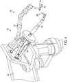
- FIG. 2 and FIGS. 3 and 4 illustrate alternate embodiments of a dental implantation system according to the present invention, the system being generally indicated by the numeral 100.
- current dental implantation procedures generally involve an imaging step, wherein CT or other appropriate images of the patient's jaw structure are obtained, and any anomalies diagnosed (i.e., whether the patient requires bone grafts to prepare the implant area). The practitioner then corrects any anomalies and proceeds with the invasive implant procedure based on the conditions associated with the patient's jaw structure, once the appropriate incisions have been made in the patient's gum.
- a dental implantation system 100 addresses the subjective aspects of current dental implantation procedures by providing a guided implantation device 150 (otherwise referred to herein as a "cutting device") configured to be guided with respect to the invasive portion of the dental implant procedure (i.e., to "prepare” the site within the patient's mouth). That is, the implantation device 150 is operably engaged with a guidance device 200.
- the guidance device 200 is adapted to operably engage the mouth of the patient. The engagement with the mouth of the patient is may through a splint 250.
- the splint 250 is configured to engage the patient's mouth in a "firm" or secure interaction (i.e., the splint 250 is engaged with the patient's teeth and does not move with respect to the patient's mouth). Since the splint 250 does not move with respect to the patient's mouth, the disposition of the splint 250 is known, and thus can be configured to provide a fiducial marker (i.e., a known origin or coordinate) which can be used, for instance, to guide the implantation device to prepare the site in the patient's mouth for receiving the dental implant 300 (see, e.g., FIG. 1B ).
- a fiducial marker i.e., a known origin or coordinate
- the splint 250 is configured to be "universally applicable” (i.e., capable of forming the secure engagement with the mouth of any patient), or at least applicable across a particular range of patients (i.e., one size fits a certain size or age of patient).
- the splint 250 may be engaged with the patient's teeth and the patient's jawbone structure then imaged using, for example, CT or any other suitable imaging technique such as, for instance, MRI.
- the imaging procedure generally involves only one jawbone structure. That is, the implant is generally intended to be placed in either the upper jawbone structure or the lower jawbone structure of the patient. As such, it may be important to obtain as clear and detailed an image of the subject jawbone structure as possible, which may be hindered by interference of the teeth of the opposing jawbone structure. Accordingly, it may be desirable to define a separation or other distinction between the upper and lower jawbone structures during the imaging procedure. Accordingly, the imaging procedure according to one embodiment of the present invention may further comprise a separator device (not shown) inserted between the patient's jawbone structures as the images are acquired.
- a separator device not shown
- such a separator device may comprise a block, plate, or other appropriate physical structure inserted into the patient's mouth, in conjunction with, or separate and discrete with respect to, the splint 250.
- the separator device may also include a separation indicator (not shown) element comprising a radiopaque material (i.e., a metallic material) that can be clearly defined in the image, wherein the separation indicator is disposed within or otherwise associated with the separator device so as to define a jawbone structure separation line, plane, or other suitable boundary.
- the separator device allows each jawbone structure to be imaged separately of the other (i.e., without interference) and, once the image is acquired, image processing techniques may be applied to the image in order to separate the image along the jawbone structure separation line, plane, or other boundary defined by the separation indicator so as to segregate (from the imaging standpoint) the jawbone structure receiving the implant.
- image processing techniques may be applied to the image in order to separate the image along the jawbone structure separation line, plane, or other boundary defined by the separation indicator so as to segregate (from the imaging standpoint) the jawbone structure receiving the implant.
- deviation from the configuration in the captured image may indicate, for example, undesirable movement of the patient during the imaging procedure.
- a curved separation line shown in the image when the separation indicator is actually a straight rod, may indicate that the patient moved during the imaging procedure, and that the procedure must be repeated to obtain a suitable image.
- the splint 250 may be configured in many different manners to accomplish the desired function as discussed herein.
- the splint 250 may be rigidly attached to the patient's mouth in an appropriate manner depending on the condition of the patient. That is, if the patient has some strong teeth capable of supporting the splint 250, the splint 250 can be attached to the teeth with an adhesive or with a suitable clamp.
- bone pins may be drilled through the splint 250 and into the patient's jawbone structure to fasten the splint 250 securely into place.
- the splint 250 may also be attached to the jawbone structure of any patient using, for example, appropriate bone screws.
- the positioning of the splint 250 with respect to the patient's mouth may not be critical or important, as long as the splint 250 remains rigidly in place.
- a fiducial marker (not shown) may then be attached to, or otherwise incorporated into, the splint 250, wherein the fiducial marker may be configured to have a geometry or other characteristic or feature that uniquely defines the fiducial marker in a three-dimensional space (i.e., such that the fiducial marker is readily identified in images of the patient's jawbone structure).
- the fiducial marker may be comprised of, for example, a radiopaque material that can be clearly defined in the image (e.g., CT or MRI).
- the implantation device 150 is engaged with an articulating arm member 350 (i.e., a robotic arm) which determines a range of motion of the implantation device 150.
- the guidance device 200 may further comprise a communication element 400 in communication between the splint 250 and the implantation device 150 and/or the arm member 350.
- the communication element 400 may comprise a mechanical linkage connecting the splint 250 to the implantation device 150 /arm member 350. That is, the communication element 400 may comprise, for example, a mechanically-tracked arm which attaches to the splint 250 engaged with the patient.
- the arm may be attached to the splint 250 (rigidly and in a known, repeatable manner) with an attachment mechanism comprising a kinematic mount. Attached to the patient in this manner via the attachment mechanism and the splint 250, the communication element 400 provides data (whether constantly, selectively, or otherwise as necessary) about the position of the patient (i.e., with respect to the fiduciary) to the implantation device 150 /arm member 350, while still providing for accurate guidance thereof in the event that the patient moves.
- the splint 250 and/or the fiducial marker determined thereby may be communicated to the implantation device 150 /arm member 350 in many different manners.
- the fiducial marker may be communicated via a communication element 400 comprising a wireless transceiver, a hardwire connection, an optical communication system, or any other suitable mechanism, whether electrical, mechanical, electromechanical, or optical in nature.
- the guidance device 200 may be further configured to include a controller device 450 (i.e., a computer device as shown in FIGS. 3 and 4 ) for determining the fiducial marker from the image of the patient's mouth having the splint 250 disposed therein, and for appropriately communicating the fiducial marker to the implantation device 150 /arm member 350.
- a controller device 450 i.e., a computer device as shown in FIGS. 3 and 4
- the controller device 450 may be further configured to receive the image of the patient's jawbone structure (having the splint 250 therein).
- the controller device 450 may be further configured to be capable of executing an implantation routine that may comprise software, hardware, or a combination thereof.
- the implantation routine thus allows the practitioner to create, for example, a virtual implantation plan based on the captured image, whether in two dimensions or three dimensions, and to manipulate the image(s) of the patient's jawbone structure in conjunction with a "virtual implant" in order to develop the virtual implantation plan or placement determination for the patient in conjunction with a computerized model based on the image(s).
- the implantation routine, virtual implantation plan, and/or placement determination may be created in relation, for example, to a coordinate system (relative or absolute), as will be appreciated by one skilled in the art, for associating the implantation parameters with the fiducial marker.
- the controller device 450 may include a peripheral device (i.e., a trackball or joystick in conjunction with, for example, 3D goggles, all not shown) to assist with or otherwise permit virtual manipulation the placement of the virtual implant(s) with respect to the image(s) in order to, for example, align the implant(s) relative to each other or relative to adjacent teeth, to align the implant(s) relative to the affected nerve, and to align the implant(s) relative to the jawbone structure.
- a peripheral device i.e., a trackball or joystick in conjunction with, for example, 3D goggles, all not shown
- the controller device 450 may be further configured to perform such manipulation manually, automatically, or semi-automatically, as necessary or desired. Because the virtual implant(s) may be manipulated in a similar manner to the image(s), the orientation or placement of the virtual implant(s) may represent the desired actual placement of the implant with respect to the patient's jawbone structure, thus providing an intuitive interface for planning the implantation procedure.
- the patient is automatically registered with the system 100 once the communication element 400 (arm) is attached to the splint 250 via the kinematic mount of the attachment mechanism. That is, the fiducial marker is automatically determined from the image(s) of the patient's jawbone structure, and the alignment and location thereof in physical space is known due to the kinematic mount connecting the arm to the splint 250.
- association of the fiducial marker with the patient's anatomy, via the controller device 450 may be accomplished in different manners.
- the registration of the image (e.g., CT scan) to the fiducial marker one method could involve the jaw structure of the patient being imaged with the fiducial marker in place, as previously discussed, wherein the patient would then be substantially immediately subjected to the implantation procedure.
- Such a scheme may be beneficial, for example, in reducing the number of visits to the practitioner by the patient.
- the practitioner may not have the imaging capabilities at hand, or may prefer to carefully determine the virtual implantation plan before carrying out the implantation procedure.
- a pre-operative imaging procedure (e.g., CT scan) may be performed on the jaw structure of the patient, without a fiducial marker in place (i.e., a "normal" scan by which the practitioner can determine the virtual implantation plan).
- This pre-operative imaging procedure can thus be performed, for example, at the practitioner's site, or at a dedicated scanning/imaging center.
- the practitioner may capture another image (e.g., CT scan, panoramic x-ray, or two single x-rays) of the patient's jaw structure.
- the controller device 450 may thus also be configured to correlate the pre-operative image (used to determine the virtual implantation procedure) with the "day of' image so as to register the fiducial marker(s) with respect to the original pre-operative image.
- Such a registration or correlation procedure may be implemented in hardware, software, or a combination thereof, as will be appreciated by one skilled in the art. The implantation procedure could then proceed as otherwise disclosed herein.
- the communication element 400 is configured to engage the arm member 350 in a manner known to the system 100, such that the position/movement characteristics of the end effector are also known.
- This communication between the communication element 400 and the arm member 350 thus allows the implantation device 150 to be registered with respect to the fiducial marker (or other reference with respect to the patient) attached to the patient via the splint 250, the kinematic mount, the communication element 400, and the arm member 350.
- the virtual implantation process, planned through the controller device 450 may be accomplished in relation to the fiducial marker (or other reference with respect to the patient) and thus translated or otherwise communicated to the system 100 for directing the implantation device 150.
- the implantation device 150 is disposed in or otherwise engaged with the end effector of the arm member 350 (robotic arm).
- the arm member 350 may be configured, for example, to provide six degrees of freedom and can also be configured to restrict or otherwise control the movement of the implantation device 150.
- the arm member 350 may have a miniature parallel structure to which the implantation device 150 is secured and allowed to have full freedom of movement when not in cutting/preparation/implantation mode. Since the implantation device 150 is attached to the end effector of the arm member 350, the patient interacting portion (i.e., the cutting/drilling tip) 500 (see, e.g., FIGS.
- a calibration element may be engaged with the implantation device 150 via a kinematic coupling (i.e., rigidly mounted thereto in a known, repeatable manner).
- a kinematic coupling i.e., rigidly mounted thereto in a known, repeatable manner.
- the calibration element is replaced with a cutting/drilling element in the implantation device 150, in a known and repeatable manner, so that the calibration parameters (i.e., the position of the distal-most point and axis of cutting/drilling) associated with the interacting portion 500 are maintained as calibrated.
- the implantation procedure i.e., cutting/drilling/insertion
- the controller device 450 is configured to control the movement of the implantation device 150 via the arm member 350 such that the action of the practitioner merely moves interacting portion 500 (i.e., the cutting/drilling element) to the appropriate starting position for the implantation procedure, with respect to the patient's jawbone structure, as determined by the controller device 450 and dictated by the virtual implantation plan.
- the controller device 450 may further dictate other parameters of the implantation device 150 such as, for example, the orientation of the path of the cutting/drilling element and the cutting/drilling distance along that path from the cutting/drilling origin, also according to the virtual implantation plan.
- the implantation device 150 is not guided by the practitioner, but is only urged by the practitioner along a procedural route determined via the virtual implantation plan and implemented via the controller device 450 and the arm member 350.
- the system 100 may be configured to restrict the practitioner to performing the implantation procedure with respect to the patient, as determined via the virtual implantation plan and implemented via the controller device 450 and the arm member 350, whereby the controller device 450 controls the allowable movement of the arm member 350 (and thus the implantation device 150 ) in accordance with the virtual implantation plan created from the image(s) of the patient's jawbone structure.
- the system 100 may be configured for restricted movement of the arm member 350 / implantation device 150, as communicated to the practitioner through tactile feedback, where, for example, the arm member 350 / implantation device 150 may be easier to move according to the virtual implantation plan, and more difficult to move if deviating from the virtual implantation plan.
- the physical structure of the arm member 350 / implantation device 150 to provide fully controlled movement according to the virtual implantation plan i.e., due to vibration, flexing of components, and/or excessive force applied by the practitioner
- the system 100 may be further configured to provide other manners of feedback to the practitioner such as, for example, via a deviation warning indicia or any other suitable audio and/or visual mechanism. Therefore, the system 100 includes provisions for actually implementing the virtual implantation plan, and thus facilitates a more accurate implantation procedure, rather than merely warning the practitioner if any procedural parameters may be inaccurate.
- the system 100 may be further configured to autonomously accomplish the virtual implantation plan, without the manipulation of the practitioner, through automatic manipulation of the arm member 350 / implantation device 150 via the controller device 450.
- the splint 250 i.e., mouthpiece
- the splint 250 is first attached to the patient's teeth, and thus provides a fiducial marker.
- the patient's jawbone structure is then imaged (with the splint 250 in place and engaged with the patient's teeth) using, for example, CT or any other appropriate imaging technique (e.g., MRI), and the image(s) communicated with the controller device 450.
- the controller device 450 may be further configured to be capable of executing an implantation routine, thus allowing the practitioner to develop an implantation plan for the patient, for example, by manipulating a virtual implant with respect to the captured image(s).
- the communication element 400 is engaged with the splint 250 (attached to the patient's mouth, with the patient being positioned in a suitable position to initiate the procedure).
- the arm member 350, implantation device 150, and interacting portion 500 thereof, are then calibrated by the practitioner (or automatically by the controller device 450 ), before the actual cutting/drilling element of the implantation device 150 is used by the practitioner (or autonomously via the controller device 450 ), via the implantation device 150 as guided by the arm member 350 and the controller device 450, to accomplish the implantation procedure as planned and dictated by the virtual implantation plan.
- a prosthetic member 600 may be prepared or otherwise modified by the dental implantation system 100 to complementarily engage the dental implant previously implanted by the implantation system 100, by facilitating an aligned engagement therebetween. That is, the dental implantation system 100 may be configured to prepare the prosthetic member(s) 600 in a manner that allows the prosthetic member 600 to precisely correspond to and engage the dental implant, as planned and dictated by the virtual implantation plan, so that correct alignment therebetween is achieved when the prosthetic member 600 is permanently placed with respect to the dental implant within the patient's mouth.
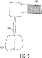
- the interacting portion 500 (e.g., drill element) of the implantation device 150 may be configured to and controlled by the controller device 450 to remove material from the prosthetic member 600 to form a borehole which is complementary to and configured to receive a corresponding portion of the dental implant, as shown in FIG. 5 .
- the dental implant may extend beyond the jawbone / gum line of the patient so as to provide a post or projecting member upon which the prosthetic member 600 may be mounted, seated, or otherwise secured within the patient's mouth.
- the borehole of the prosthetic member 600 may be particularly formed by the dental implantation system 100 to facilitate alignment of the prosthetic member 600 with the dental implant.
- the prosthetic member 600 may be registered with the implantation routine (i.e., registered with respect to the fiducial marker associated with the splint 250 ).
- the prosthetic member 600 may be introduced within the virtual implantation plan and "virtually" registered with the system 100 in relation to the fiducial marker associated with the splint 250.
- the prosthetic member 600 may be appropriately positioned within the patient's mouth at the time of the initial scan of the patient's jawbone structure, as previously described, so as to be physically registered with the fiducial marker associated with the splint 250.
- the prosthetic member 600 may also have one or more fiducial markers (e.g., metallic bearing members) attached to, incorporated in, or otherwise associated therewith, wherein the prosthetic member fiducial marker(s) may be configured to have a particular geometry or other unique characteristic or feature that readily identifies and defines those fiducial marker(s) in the images of the patient's jawbone structure, as well as in comparison to the fiducial marker associated with the splint 250.
- the fiducial marker(s) associated with the prosthetic member 600 may be comprised of, for example, a radiopaque material that can be clearly defined in the image (e.g., CT or MRI).
- the configuration of the prosthetic member 600 with respect those fiducial marker(s) can be determined, and thus the system 100 can be configured and guided according to the prosthetic member fiducial marker(s) (i.e., according to a coordinate system associated with the prosthetic member 600 and registered with the system 100 ) so as to allow the implantation device 150 to prepare the borehole at the appropriate site in the prosthetic member 600.
- the prosthetic member fiducial marker(s) may be identified in the imaging scans and then related to / registered with the system 100 so as to allow the borehole to be appropriately formed in the prosthetic member 600. That is, once the prosthetic member 600 is registered with or known to the controller device 450, the interacting portion 500 (or a calibration member), whether coupled to the implantation arm 150 / arm member 350 or not, may be brought into engagement with the fiducial member(s) associated with the physical prosthetic member 600, with the prosthetic member 600 fastened or otherwise held in a static position, to associate the physical prosthetic device 600 with the system such that the borehole can be formed therein according to the virtual implantation plan. In any instance, the capability of preparing the prosthetic member 600 via the system 100 provides an expedited dental implantation process by facilitating a more accurate alignment between the dental implant and prosthetic member 600.
Landscapes
- Health & Medical Sciences (AREA)
- Oral & Maxillofacial Surgery (AREA)
- Life Sciences & Earth Sciences (AREA)
- Dentistry (AREA)
- Animal Behavior & Ethology (AREA)
- General Health & Medical Sciences (AREA)
- Public Health (AREA)
- Veterinary Medicine (AREA)
- Epidemiology (AREA)
- Surgery (AREA)
- Nuclear Medicine, Radiotherapy & Molecular Imaging (AREA)
- Engineering & Computer Science (AREA)
- Physics & Mathematics (AREA)
- Optics & Photonics (AREA)
- Pathology (AREA)
- Radiology & Medical Imaging (AREA)
- Molecular Biology (AREA)
- Biophysics (AREA)
- Biomedical Technology (AREA)
- Heart & Thoracic Surgery (AREA)
- Medical Informatics (AREA)
- Orthopedic Medicine & Surgery (AREA)
- Dental Prosthetics (AREA)
- Apparatus For Radiation Diagnosis (AREA)
- Dental Tools And Instruments Or Auxiliary Dental Instruments (AREA)
Description
- Embodiments of the present invention are directed toward robotic systems for dental surgery and, more particularly, to a guided dental implantation system and associated device.
- Patients who are missing teeth, whether it be one, several, or an entire arch, may be candidates for dental implants. Patients who want a more permanent solution than dentures, bridges, or other tooth replacement measures may also be interested in dental implants.
-
US 5,607,303 describes a dental drilling machine with displacement equipment installed thereon. The displacement equipment is adapted to hold back oral cavity organs during a dental surgery. The drilling machine with the displacement equipment is designed for one-handed use. - The dental implantation procedure generally involves an invasive incision into the gum of the patient in order to allow the practitioner to view the underlying jawbone structure. A hole is then drilled into the jawbone structure, into which a dental implant is placed (see, e.g.,
FIG. 1A ). In some instances, the dental implant may be shaped, for example, like a screw. Once the dental implant is inserted into the jawbone structure, an external post is attached to the dental implant (see, e.g.,FIG. 1B ), and a prosthetic cap (tooth reproduction) attached to the post (see, e.g.,FIG. 1C ). - With computerized tomography (CT) and other imaging scans becoming more common, the practitioner may be able to graphically visualize the jawbone structure, without or before the invasive incision. However, the alignment of the dental implant with respect to the jawbone structure and/or relative to other implants or teeth may be an important factor in determining, for example, the life of the dental implant, the appearance thereof, and the comfort to the patient. If the dental implant is poorly or otherwise not optimally placed, the dental implant can undesirably fail (or at least have a shorter service life), may undesirably cause other teeth or dental implants to be compromised, and/or damage proximal nerves.
-
EP 1 743 594 A1 , which is considered to be the closest prior art to claim 1, discloses a computer-controlled dental treatment system, including: a dental chair for receiving a patient to be treated; a robotic arm carrying a dental tool holder for holding a dental tool to be used in rendering a selected dental treatment, and for manipulating the dental tool with respect to the patient's head during the dental treatment; and a control system programmable to control the robotic arm to manipulate the dental tool in accordance with the selected dental treatment to be rendered to the patient. - Thus, there exists a need for a system for providing an improved dental implantation procedure that addresses the noted shortcomings of current procedures, and facilitates, for example, effective pre-surgical planning and guidance during the surgical procedure.
- The above and other needs are met by the present invention which, in one aspect, provides a dental implantation system, comprising an implantation device adapted to prepare a site within a mouth of a patient for receiving a dental implant. A guidance device is operably engaged with the implantation device and is adapted to operably engage the mouth of the patient. The engagement between the guidance device and the mouth of the patient provides a fiducial marker for guiding the implantation device to prepare the site for receiving the dental implant.
- Also described is a method not comprising part of the invention of implanting a dental implant, comprising determining a fiducial marker from an engagement between a guidance device and a mouth of a patient; and guiding an implantation device operably engaged with the guidance device, with respect to the fiducial marker, so as to prepare a site within the mouth of the patient for receiving the dental implant.
- Various other aspects of the present invention are directed to component devices, as otherwise disclosed herein. Associated methods facilitating the dental implantation system and method of implanting a dental implant not comprising part of the invention are also described.
- Aspects of the present invention thus provide distinct advantages as otherwise detailed herein.
- Having thus described the invention in general terms, reference will now be made to the accompanying drawings, which are not necessarily drawn to scale, and wherein:
-
FIGS. 1A-1C schematically illustrate a dental implantation procedure with respect to the mouth of a patient; -
FIG. 2 schematically illustrates a dental implantation system according to one embodiment of the present invention; -
FIGS. 3 and4 schematically illustrate a dental implantation system according to an alternate embodiment of the present invention; and -
FIG. 5 schematically illustrates preparation of a prosthetic member with a dental implantation system according to one embodiment of the present invention. - The present invention now will be described more fully hereinafter with reference to the accompanying drawings, in which some, but not all embodiments of the inventions are shown. Indeed, these inventions may be embodied in many different forms and should not be construed as limited to the embodiments set forth herein; rather, these embodiments are provided so that this disclosure will satisfy applicable legal requirements. Like numbers refer to like elements throughout.
-
FIG. 2 andFIGS. 3 and 4 illustrate alternate embodiments of a dental implantation system according to the present invention, the system being generally indicated by thenumeral 100. As previously indicated, current dental implantation procedures generally involve an imaging step, wherein CT or other appropriate images of the patient's jaw structure are obtained, and any anomalies diagnosed (i.e., whether the patient requires bone grafts to prepare the implant area). The practitioner then corrects any anomalies and proceeds with the invasive implant procedure based on the conditions associated with the patient's jaw structure, once the appropriate incisions have been made in the patient's gum. - A
dental implantation system 100 according to various aspects of the present invention addresses the subjective aspects of current dental implantation procedures by providing a guided implantation device 150 (otherwise referred to herein as a "cutting device") configured to be guided with respect to the invasive portion of the dental implant procedure (i.e., to "prepare" the site within the patient's mouth). That is, theimplantation device 150 is operably engaged with aguidance device 200. Theguidance device 200 is adapted to operably engage the mouth of the patient. The engagement with the mouth of the patient is may through asplint 250. In one instance, thesplint 250 is configured to engage the patient's mouth in a "firm" or secure interaction (i.e., thesplint 250 is engaged with the patient's teeth and does not move with respect to the patient's mouth). Since thesplint 250 does not move with respect to the patient's mouth, the disposition of thesplint 250 is known, and thus can be configured to provide a fiducial marker (i.e., a known origin or coordinate) which can be used, for instance, to guide the implantation device to prepare the site in the patient's mouth for receiving the dental implant 300 (see, e.g.,FIG. 1B ). In one aspect, thesplint 250 is configured to be "universally applicable" (i.e., capable of forming the secure engagement with the mouth of any patient), or at least applicable across a particular range of patients (i.e., one size fits a certain size or age of patient). In order to determine the fiducial marker, according to one aspect of the invention, thesplint 250 may be engaged with the patient's teeth and the patient's jawbone structure then imaged using, for example, CT or any other suitable imaging technique such as, for instance, MRI. - With respect to the imaging procedure, one skilled in the art will appreciate that the implantation procedure generally involves only one jawbone structure. That is, the implant is generally intended to be placed in either the upper jawbone structure or the lower jawbone structure of the patient. As such, it may be important to obtain as clear and detailed an image of the subject jawbone structure as possible, which may be hindered by interference of the teeth of the opposing jawbone structure. Accordingly, it may be desirable to define a separation or other distinction between the upper and lower jawbone structures during the imaging procedure. Accordingly, the imaging procedure according to one embodiment of the present invention may further comprise a separator device (not shown) inserted between the patient's jawbone structures as the images are acquired. For example, such a separator device may comprise a block, plate, or other appropriate physical structure inserted into the patient's mouth, in conjunction with, or separate and discrete with respect to, the
splint 250. The separator device may also include a separation indicator (not shown) element comprising a radiopaque material (i.e., a metallic material) that can be clearly defined in the image, wherein the separation indicator is disposed within or otherwise associated with the separator device so as to define a jawbone structure separation line, plane, or other suitable boundary. Accordingly, the separator device allows each jawbone structure to be imaged separately of the other (i.e., without interference) and, once the image is acquired, image processing techniques may be applied to the image in order to separate the image along the jawbone structure separation line, plane, or other boundary defined by the separation indicator so as to segregate (from the imaging standpoint) the jawbone structure receiving the implant. One skilled in the art will also appreciate that, since the configuration of the separation indicator is known, deviation from the configuration in the captured image may indicate, for example, undesirable movement of the patient during the imaging procedure. For example, a curved separation line shown in the image, when the separation indicator is actually a straight rod, may indicate that the patient moved during the imaging procedure, and that the procedure must be repeated to obtain a suitable image. - One skilled in the art will also appreciate that the
splint 250 may be configured in many different manners to accomplish the desired function as discussed herein. For example, thesplint 250 may be rigidly attached to the patient's mouth in an appropriate manner depending on the condition of the patient. That is, if the patient has some strong teeth capable of supporting thesplint 250, thesplint 250 can be attached to the teeth with an adhesive or with a suitable clamp. For edentulous patients (i.e., without teeth), bone pins may be drilled through thesplint 250 and into the patient's jawbone structure to fasten thesplint 250 securely into place. Thesplint 250 may also be attached to the jawbone structure of any patient using, for example, appropriate bone screws. In one aspect, the positioning of thesplint 250 with respect to the patient's mouth may not be critical or important, as long as thesplint 250 remains rigidly in place. A fiducial marker (not shown) may then be attached to, or otherwise incorporated into, thesplint 250, wherein the fiducial marker may be configured to have a geometry or other characteristic or feature that uniquely defines the fiducial marker in a three-dimensional space (i.e., such that the fiducial marker is readily identified in images of the patient's jawbone structure). In such instances, the fiducial marker may be comprised of, for example, a radiopaque material that can be clearly defined in the image (e.g., CT or MRI). - In one instance, the
implantation device 150 is engaged with an articulating arm member 350 (i.e., a robotic arm) which determines a range of motion of theimplantation device 150. Theguidance device 200, in such instances, may further comprise acommunication element 400 in communication between thesplint 250 and theimplantation device 150 and/or thearm member 350. For example, thecommunication element 400 may comprise a mechanical linkage connecting thesplint 250 to theimplantation device 150/arm member 350. That is, thecommunication element 400 may comprise, for example, a mechanically-tracked arm which attaches to thesplint 250 engaged with the patient. In some instances, the arm may be attached to the splint 250 (rigidly and in a known, repeatable manner) with an attachment mechanism comprising a kinematic mount. Attached to the patient in this manner via the attachment mechanism and thesplint 250, thecommunication element 400 provides data (whether constantly, selectively, or otherwise as necessary) about the position of the patient (i.e., with respect to the fiduciary) to theimplantation device 150/arm member 350, while still providing for accurate guidance thereof in the event that the patient moves. However, one skilled in the art will appreciate that thesplint 250 and/or the fiducial marker determined thereby may be communicated to theimplantation device 150/arm member 350 in many different manners. For example, the fiducial marker may be communicated via acommunication element 400 comprising a wireless transceiver, a hardwire connection, an optical communication system, or any other suitable mechanism, whether electrical, mechanical, electromechanical, or optical in nature. In any instance, theguidance device 200 may be further configured to include a controller device 450 (i.e., a computer device as shown inFIGS. 3 and4 ) for determining the fiducial marker from the image of the patient's mouth having thesplint 250 disposed therein, and for appropriately communicating the fiducial marker to theimplantation device 150/arm member 350. - In one aspect, the
controller device 450 may be further configured to receive the image of the patient's jawbone structure (having thesplint 250 therein). In some instances, thecontroller device 450 may be further configured to be capable of executing an implantation routine that may comprise software, hardware, or a combination thereof. The implantation routine thus allows the practitioner to create, for example, a virtual implantation plan based on the captured image, whether in two dimensions or three dimensions, and to manipulate the image(s) of the patient's jawbone structure in conjunction with a "virtual implant" in order to develop the virtual implantation plan or placement determination for the patient in conjunction with a computerized model based on the image(s). In some aspects, the implantation routine, virtual implantation plan, and/or placement determination may be created in relation, for example, to a coordinate system (relative or absolute), as will be appreciated by one skilled in the art, for associating the implantation parameters with the fiducial marker. In other aspects, thecontroller device 450 may include a peripheral device (i.e., a trackball or joystick in conjunction with, for example, 3D goggles, all not shown) to assist with or otherwise permit virtual manipulation the placement of the virtual implant(s) with respect to the image(s) in order to, for example, align the implant(s) relative to each other or relative to adjacent teeth, to align the implant(s) relative to the affected nerve, and to align the implant(s) relative to the jawbone structure. Thecontroller device 450 may be further configured to perform such manipulation manually, automatically, or semi-automatically, as necessary or desired. Because the virtual implant(s) may be manipulated in a similar manner to the image(s), the orientation or placement of the virtual implant(s) may represent the desired actual placement of the implant with respect to the patient's jawbone structure, thus providing an intuitive interface for planning the implantation procedure. The patient is automatically registered with thesystem 100 once the communication element 400 (arm) is attached to thesplint 250 via the kinematic mount of the attachment mechanism. That is, the fiducial marker is automatically determined from the image(s) of the patient's jawbone structure, and the alignment and location thereof in physical space is known due to the kinematic mount connecting the arm to thesplint 250. - One skilled in the art will further appreciate that the association of the fiducial marker with the patient's anatomy, via the
controller device 450, may be accomplished in different manners. For example, with respect to the registration of the image (e.g., CT scan) to the fiducial marker, one method could involve the jaw structure of the patient being imaged with the fiducial marker in place, as previously discussed, wherein the patient would then be substantially immediately subjected to the implantation procedure. Such a scheme may be beneficial, for example, in reducing the number of visits to the practitioner by the patient. However, in some instances, the practitioner may not have the imaging capabilities at hand, or may prefer to carefully determine the virtual implantation plan before carrying out the implantation procedure. In both such instances, the patient will likely be required to return to the practitioner at a later time. Accordingly, in such situations, a pre-operative imaging procedure (e.g., CT scan) may be performed on the jaw structure of the patient, without a fiducial marker in place (i.e., a "normal" scan by which the practitioner can determine the virtual implantation plan). This pre-operative imaging procedure can thus be performed, for example, at the practitioner's site, or at a dedicated scanning/imaging center. Subsequently, immediately prior to the implantation procedure being performed, and with the fiducial marker(s) engaged with the jaw structure of the patient, the practitioner may capture another image (e.g., CT scan, panoramic x-ray, or two single x-rays) of the patient's jaw structure. Thecontroller device 450 may thus also be configured to correlate the pre-operative image (used to determine the virtual implantation procedure) with the "day of' image so as to register the fiducial marker(s) with respect to the original pre-operative image. Such a registration or correlation procedure may be implemented in hardware, software, or a combination thereof, as will be appreciated by one skilled in the art. The implantation procedure could then proceed as otherwise disclosed herein. - In any instance, the
communication element 400 is configured to engage thearm member 350 in a manner known to thesystem 100, such that the position/movement characteristics of the end effector are also known. This communication between thecommunication element 400 and thearm member 350 thus allows theimplantation device 150 to be registered with respect to the fiducial marker (or other reference with respect to the patient) attached to the patient via thesplint 250, the kinematic mount, thecommunication element 400, and thearm member 350. In this manner, the virtual implantation process, planned through thecontroller device 450, may be accomplished in relation to the fiducial marker (or other reference with respect to the patient) and thus translated or otherwise communicated to thesystem 100 for directing theimplantation device 150. - The
implantation device 150 is disposed in or otherwise engaged with the end effector of the arm member 350 (robotic arm). Thearm member 350 may be configured, for example, to provide six degrees of freedom and can also be configured to restrict or otherwise control the movement of theimplantation device 150. Further, thearm member 350 may have a miniature parallel structure to which theimplantation device 150 is secured and allowed to have full freedom of movement when not in cutting/preparation/implantation mode. Since theimplantation device 150 is attached to the end effector of thearm member 350, the patient interacting portion (i.e., the cutting/drilling tip) 500 (see, e.g.,FIGS. 2 and4 ) of theimplantation device 150 must be in a known position (i.e., known to the system 100) relative to thearm member 350. In some aspects, in order to calibrate the interactingportion 500 of theimplantation device 150 with respect to the fiducial marker, a calibration element may be engaged with theimplantation device 150 via a kinematic coupling (i.e., rigidly mounted thereto in a known, repeatable manner). One skilled in the art will thus appreciate that the interactingportion 500 of theimplantation device 150 can then be calibrated with various tip calibrating methods (i.e., invariant point, etc.). Once calibrated, the calibration element is replaced with a cutting/drilling element in theimplantation device 150, in a known and repeatable manner, so that the calibration parameters (i.e., the position of the distal-most point and axis of cutting/drilling) associated with the interactingportion 500 are maintained as calibrated. - With the alignment with respect to the patient established and known by the
system 100, and the virtual implantation plan developed through thecontroller device 450, the implantation procedure (i.e., cutting/drilling/insertion) can then be initiated by the practitioner moving theimplantation device 150 toward the patient's mouth (having thesplint 250 engaged therewith). In such instances, thecontroller device 450 is configured to control the movement of theimplantation device 150 via thearm member 350 such that the action of the practitioner merely moves interacting portion 500 (i.e., the cutting/drilling element) to the appropriate starting position for the implantation procedure, with respect to the patient's jawbone structure, as determined by thecontroller device 450 and dictated by the virtual implantation plan. Once the cutting/drilling element is in the position dictated by thecontroller device 450, the invasive portion of the procedure can then be initiated, wherein thecontroller device 450 may further dictate other parameters of theimplantation device 150 such as, for example, the orientation of the path of the cutting/drilling element and the cutting/drilling distance along that path from the cutting/drilling origin, also according to the virtual implantation plan. In these instances, one distinction of thesystem 100 disclosed herein is that theimplantation device 150 is not guided by the practitioner, but is only urged by the practitioner along a procedural route determined via the virtual implantation plan and implemented via thecontroller device 450 and thearm member 350. That is, thesystem 100 may be configured to restrict the practitioner to performing the implantation procedure with respect to the patient, as determined via the virtual implantation plan and implemented via thecontroller device 450 and thearm member 350, whereby thecontroller device 450 controls the allowable movement of the arm member 350 (and thus the implantation device 150) in accordance with the virtual implantation plan created from the image(s) of the patient's jawbone structure. For instance, thesystem 100 may be configured for restricted movement of thearm member 350 /implantation device 150, as communicated to the practitioner through tactile feedback, where, for example, thearm member 350 /implantation device 150 may be easier to move according to the virtual implantation plan, and more difficult to move if deviating from the virtual implantation plan. One skilled in the art will also appreciate, however, that the physical structure of thearm member 350 /implantation device 150 to provide fully controlled movement according to the virtual implantation plan (i.e., due to vibration, flexing of components, and/or excessive force applied by the practitioner) and, as such, thesystem 100 may be further configured to provide other manners of feedback to the practitioner such as, for example, via a deviation warning indicia or any other suitable audio and/or visual mechanism. Therefore, thesystem 100 includes provisions for actually implementing the virtual implantation plan, and thus facilitates a more accurate implantation procedure, rather than merely warning the practitioner if any procedural parameters may be inaccurate. One skilled in the art will also appreciate, however, that, in some instances, thesystem 100 may be further configured to autonomously accomplish the virtual implantation plan, without the manipulation of the practitioner, through automatic manipulation of thearm member 350 /implantation device 150 via thecontroller device 450. - In one exemplary surgical procedure using a
dental implantation system 100, as disclosed herein, the splint 250 (i.e., mouthpiece) is first attached to the patient's teeth, and thus provides a fiducial marker. The patient's jawbone structure is then imaged (with thesplint 250 in place and engaged with the patient's teeth) using, for example, CT or any other appropriate imaging technique (e.g., MRI), and the image(s) communicated with thecontroller device 450. Thecontroller device 450 may be further configured to be capable of executing an implantation routine, thus allowing the practitioner to develop an implantation plan for the patient, for example, by manipulating a virtual implant with respect to the captured image(s). Once the virtual implantation plan is created, thecommunication element 400 is engaged with the splint 250 (attached to the patient's mouth, with the patient being positioned in a suitable position to initiate the procedure). Thearm member 350,implantation device 150, and interactingportion 500 thereof, are then calibrated by the practitioner (or automatically by the controller device 450), before the actual cutting/drilling element of theimplantation device 150 is used by the practitioner (or autonomously via the controller device 450), via theimplantation device 150 as guided by thearm member 350 and thecontroller device 450, to accomplish the implantation procedure as planned and dictated by the virtual implantation plan. - According to other aspects of the present disclosure, a prosthetic member 600 (e.g., a denture, reproduction tooth, etc.) may be prepared or otherwise modified by the
dental implantation system 100 to complementarily engage the dental implant previously implanted by theimplantation system 100, by facilitating an aligned engagement therebetween. That is, thedental implantation system 100 may be configured to prepare the prosthetic member(s) 600 in a manner that allows theprosthetic member 600 to precisely correspond to and engage the dental implant, as planned and dictated by the virtual implantation plan, so that correct alignment therebetween is achieved when theprosthetic member 600 is permanently placed with respect to the dental implant within the patient's mouth. In one example, the interacting portion 500 (e.g., drill element) of theimplantation device 150 may be configured to and controlled by thecontroller device 450 to remove material from theprosthetic member 600 to form a borehole which is complementary to and configured to receive a corresponding portion of the dental implant, as shown inFIG. 5 . For example, in one instance, the dental implant may extend beyond the jawbone / gum line of the patient so as to provide a post or projecting member upon which theprosthetic member 600 may be mounted, seated, or otherwise secured within the patient's mouth. Thus, the borehole of theprosthetic member 600 may be particularly formed by thedental implantation system 100 to facilitate alignment of theprosthetic member 600 with the dental implant. - In order to form the borehole in the appropriate location or site of the
prosthetic member 600, theprosthetic member 600 may be registered with the implantation routine (i.e., registered with respect to the fiducial marker associated with the splint 250). In one instance, theprosthetic member 600 may be introduced within the virtual implantation plan and "virtually" registered with thesystem 100 in relation to the fiducial marker associated with thesplint 250. In other instances, theprosthetic member 600 may be appropriately positioned within the patient's mouth at the time of the initial scan of the patient's jawbone structure, as previously described, so as to be physically registered with the fiducial marker associated with thesplint 250. In such instances, theprosthetic member 600 may also have one or more fiducial markers (e.g., metallic bearing members) attached to, incorporated in, or otherwise associated therewith, wherein the prosthetic member fiducial marker(s) may be configured to have a particular geometry or other unique characteristic or feature that readily identifies and defines those fiducial marker(s) in the images of the patient's jawbone structure, as well as in comparison to the fiducial marker associated with thesplint 250. As disclosed, the fiducial marker(s) associated with theprosthetic member 600 may be comprised of, for example, a radiopaque material that can be clearly defined in the image (e.g., CT or MRI). By implementing the prosthetic member fiducial marker(s), the configuration of theprosthetic member 600 with respect those fiducial marker(s) can be determined, and thus thesystem 100 can be configured and guided according to the prosthetic member fiducial marker(s) (i.e., according to a coordinate system associated with theprosthetic member 600 and registered with the system 100) so as to allow theimplantation device 150 to prepare the borehole at the appropriate site in theprosthetic member 600. - As a result of the imaging (and/or virtual implantation plan), the prosthetic member fiducial marker(s) may be identified in the imaging scans and then related to / registered with the
system 100 so as to allow the borehole to be appropriately formed in theprosthetic member 600. That is, once theprosthetic member 600 is registered with or known to thecontroller device 450, the interacting portion 500 (or a calibration member), whether coupled to theimplantation arm 150 /arm member 350 or not, may be brought into engagement with the fiducial member(s) associated with the physicalprosthetic member 600, with theprosthetic member 600 fastened or otherwise held in a static position, to associate the physicalprosthetic device 600 with the system such that the borehole can be formed therein according to the virtual implantation plan. In any instance, the capability of preparing theprosthetic member 600 via thesystem 100 provides an expedited dental implantation process by facilitating a more accurate alignment between the dental implant andprosthetic member 600.
Claims (6)
- A dental implantation system (100), comprising:an implantation device (150) adapted to prepare a site within a mouth of a patient for receiving a dental implant;a guidance device (200) comprising a communication element (400), the communication element (400) being operably engaged and in communication with the implantation device (150); and a splint (250) adapted to engage the mouth of the patient, the splint (250) being in communication with the guidance device (200) and cooperable therewith to determine a fiducial marker, wherein the fiducial marker is configured to be communicated to the implantation device (150) via the communication element (400) attached to the splint (250) such that the implantation device (150) is in communication with the fiducial marker, and the guidance device (200) thereby being configured to guide the implantation device (150) in relation to the fiducial marker to prepare the site for receiving the dental implant.
- A system (100) according to Claim 1 further comprising an arm member (350) in communication with the guidance device (200) and responsive thereto to guide the implantation device (150) to prepare the site for receiving the dental implant.
- A system (100) according to Claim 2, wherein the arm member (350) comprises an articulating arm member (350) configured to determine a range of motion of the implantation device (150).
- A system (100) according to Claim 1 further comprising a dental implant planning system configured to facilitate graphical manipulation of a jawbone structural image of the patient for forming a plan of the site within the mouth of the patient for receiving the dental implant, and wherein the dental implant planning system is further configured to be in communication with at least the guidance device (200) for translating the plan to the implantation device (150).
- A system (100) according to Claim 1, wherein the communication element (400) comprises a wireless communication element capable of providing wireless communication between the implantation device (150) and the fiducial marker.
- A system (100) according to Claim 1, wherein the guidance device (200) comprises a controller device (450) configured to determine parameters associated with the fiducial marker and to communicate the parameters associated with the fiducial marker to the implantation device (150).
Priority Applications (1)
| Application Number | Priority Date | Filing Date | Title |
|---|---|---|---|
| EP20156071.1A EP3673861B1 (en) | 2008-04-02 | 2009-04-01 | Guided dental implantation system |
Applications Claiming Priority (2)
| Application Number | Priority Date | Filing Date | Title |
|---|---|---|---|
| US4172208P | 2008-04-02 | 2008-04-02 | |
| PCT/US2009/039081 WO2009124110A1 (en) | 2008-04-02 | 2009-04-01 | Guided dental implantation system and associated device and method |
Related Child Applications (1)
| Application Number | Title | Priority Date | Filing Date |
|---|---|---|---|
| EP20156071.1A Division EP3673861B1 (en) | 2008-04-02 | 2009-04-01 | Guided dental implantation system |
Publications (2)
| Publication Number | Publication Date |
|---|---|
| EP2259746A1 EP2259746A1 (en) | 2010-12-15 |
| EP2259746B1 true EP2259746B1 (en) | 2020-02-12 |
Family
ID=40811160
Family Applications (2)
| Application Number | Title | Priority Date | Filing Date |
|---|---|---|---|
| EP09727058.1A Active EP2259746B1 (en) | 2008-04-02 | 2009-04-01 | Guided dental implantation system |
| EP20156071.1A Active EP3673861B1 (en) | 2008-04-02 | 2009-04-01 | Guided dental implantation system |
Family Applications After (1)
| Application Number | Title | Priority Date | Filing Date |
|---|---|---|---|
| EP20156071.1A Active EP3673861B1 (en) | 2008-04-02 | 2009-04-01 | Guided dental implantation system |
Country Status (6)
| Country | Link |
|---|---|
| US (2) | US8808000B2 (en) |
| EP (2) | EP2259746B1 (en) |
| KR (1) | KR101557383B1 (en) |
| ES (2) | ES2939259T3 (en) |
| IL (2) | IL208415A (en) |
| WO (1) | WO2009124110A1 (en) |
Families Citing this family (54)
| Publication number | Priority date | Publication date | Assignee | Title |
|---|---|---|---|---|
| US20090069804A1 (en) * | 2007-09-12 | 2009-03-12 | Jensen Jeffrey L | Apparatus for efficient power delivery |
| EP2429444B1 (en) | 2009-05-11 | 2024-02-28 | TriAgenics, Inc. | Therapeutic tooth bud ablation |
| US10022202B2 (en) | 2013-03-15 | 2018-07-17 | Triagenics, Llc | Therapeutic tooth bud ablation |
| WO2014143014A1 (en) | 2013-03-15 | 2014-09-18 | Triagenics, Llc | Therapeutic tooth bud ablation |
| EP2525736A4 (en) * | 2010-01-22 | 2013-08-21 | Prec Through Imaging Llc | Dental implantation system and method |
| US9516207B2 (en) * | 2010-06-24 | 2016-12-06 | Marc S. Lemchen | Exam-cam robotic systems and methods |
| DE102010031018A1 (en) * | 2010-07-06 | 2012-01-12 | Sirona Dental Systems Gmbh | Method and clamping device for producing a dental surgical template |
| HUP1000387A2 (en) * | 2010-07-22 | 2012-02-28 | Laszlo Dr Kolozsvary | Process and apparatus for computer-controlled restoration of teeth |
| US8620045B2 (en) * | 2010-10-15 | 2013-12-31 | Bruce William Adams | System , method and article for measuring and reporting craniomandibular biomechanical functions |
| EP3150113A1 (en) | 2010-12-13 | 2017-04-05 | Ortho Kinematics, Inc. | Methods, systems and devices for clinical data reporting and surgical navigation |
| US11304777B2 (en) | 2011-10-28 | 2022-04-19 | Navigate Surgical Technologies, Inc | System and method for determining the three-dimensional location and orientation of identification markers |
| US9585721B2 (en) | 2011-10-28 | 2017-03-07 | Navigate Surgical Technologies, Inc. | System and method for real time tracking and modeling of surgical site |
| US8938282B2 (en) | 2011-10-28 | 2015-01-20 | Navigate Surgical Technologies, Inc. | Surgical location monitoring system and method with automatic registration |
| US9198737B2 (en) | 2012-11-08 | 2015-12-01 | Navigate Surgical Technologies, Inc. | System and method for determining the three-dimensional location and orientation of identification markers |
| US9566123B2 (en) | 2011-10-28 | 2017-02-14 | Navigate Surgical Technologies, Inc. | Surgical location monitoring system and method |
| US8908918B2 (en) | 2012-11-08 | 2014-12-09 | Navigate Surgical Technologies, Inc. | System and method for determining the three-dimensional location and orientation of identification markers |
| US9554763B2 (en) | 2011-10-28 | 2017-01-31 | Navigate Surgical Technologies, Inc. | Soft body automatic registration and surgical monitoring system |
| WO2013106430A1 (en) * | 2012-01-09 | 2013-07-18 | Old Dominion University Research Foundation | Method and system for automated dental implantation |
| US20130261433A1 (en) * | 2012-03-28 | 2013-10-03 | Navident Technologies, Inc. | Haptic simulation and surgical location monitoring system and method |
| JP2013236749A (en) * | 2012-05-15 | 2013-11-28 | Denso Corp | Apparatus for supporting dental implantation surgery |
| JP5832379B2 (en) | 2012-06-04 | 2015-12-16 | 株式会社デンソー | Opener |
| TW201429455A (en) * | 2013-01-24 | 2014-08-01 | Eped Inc | Dental guiding and positioning system consistency control device |
| US9438264B1 (en) | 2015-09-10 | 2016-09-06 | Realtek Semiconductor Corp. | High-speed capacitive digital-to-analog converter and method thereof |
| US9877810B2 (en) * | 2013-03-15 | 2018-01-30 | Neocis Inc. | Method for conducting a guided sinus lift procedure |
| US9489738B2 (en) | 2013-04-26 | 2016-11-08 | Navigate Surgical Technologies, Inc. | System and method for tracking non-visible structure of a body with multi-element fiducial |
| EP3033873A1 (en) | 2013-08-13 | 2016-06-22 | Navigate Surgical Technologies Inc. | System and method for focusing imaging devices |
| EP3033025A1 (en) | 2013-08-13 | 2016-06-22 | Navigate Surgical Technologies Inc. | Method for determining the location and orientation of a fiducial reference |
| KR102352789B1 (en) * | 2014-03-04 | 2022-01-20 | 네오시스, 인크. | Surgical robot system for integrated surgical planning and implant preparation, and associated method |
| US9283055B2 (en) | 2014-04-01 | 2016-03-15 | FPJ Enterprises, LLC | Method for establishing drill trajectory for dental implants |
| EP3229723B1 (en) * | 2014-12-09 | 2020-12-09 | Biomet 3I, LLC | Robotic device for dental surgery |
| ES2797683T3 (en) | 2015-01-22 | 2020-12-03 | Neocis Inc | Interactive Guidance and Tamper Detection Arrangements for a Surgical Robotic System |
| KR20170125360A (en) | 2015-03-12 | 2017-11-14 | 네오시스, 인크. | A method and apparatus for using a physical object to manipulate corresponding virtual objects in a virtual environment, |
| KR101653494B1 (en) * | 2015-04-30 | 2016-09-01 | 김양수 | The method and system for fine operation of tooth |
| WO2016196592A1 (en) * | 2015-06-02 | 2016-12-08 | Biomet 3I, Llc | Robotic device for dental surgery |
| US20160354161A1 (en) | 2015-06-05 | 2016-12-08 | Ortho Kinematics, Inc. | Methods for data processing for intra-operative navigation systems |
| JP6500708B2 (en) * | 2015-09-03 | 2019-04-17 | 株式会社デンソー | Medical support device |
| CN108289727A (en) * | 2015-10-29 | 2018-07-17 | 李岷炡 | Dental self-auxiliary device |
| JP6497299B2 (en) * | 2015-11-12 | 2019-04-10 | 株式会社デンソー | Medical support device |
| EP3380020A4 (en) | 2015-11-23 | 2019-11-13 | Launchpad Medical, LLC | Implantable objects, guiding devices, and methods of use thereof |
| JP6593180B2 (en) | 2016-01-08 | 2019-10-23 | 株式会社デンソー | Medical support device |
| CN114948213A (en) | 2016-01-26 | 2022-08-30 | 网络牙科(美国)公司 | Automated dental treatment system |
| US10016242B2 (en) * | 2016-06-06 | 2018-07-10 | Neocis Inc. | Splint device for forming a fiducial marker for a surgical robot guidance system, and associated method |
| US11259894B2 (en) | 2016-09-19 | 2022-03-01 | Neocis, Inc. | Tracking and guidance arrangement for a surgical robot system and related method |
| CN108201470B (en) * | 2016-12-16 | 2021-09-10 | 上海铂联医疗科技有限公司 | Autonomous dental implant robot system and equipment and method thereof |
| CA3059462A1 (en) * | 2017-02-22 | 2018-08-30 | Christopher John Ciriello | Automated dental treatment system |
| TWI783995B (en) * | 2017-04-28 | 2022-11-21 | 美商尼奧西斯股份有限公司 | Methods for conducting guided oral and maxillofacial procedures, and associated system |
| WO2019092236A1 (en) | 2017-11-10 | 2019-05-16 | 3Shape A/S | Computed tomography reconstruction of moving bodies |
| US11154375B2 (en) * | 2018-02-02 | 2021-10-26 | Brachium, Inc. | Medical robotic work station |
| EP3979938A4 (en) | 2019-06-06 | 2023-06-28 | TriAgenics, Inc. | Ablation probe systems |
| US11963829B2 (en) | 2020-02-06 | 2024-04-23 | Patrick C. Bell | Fiducial markers for analyzing human jaws |
| US11612451B2 (en) | 2020-02-06 | 2023-03-28 | Patrick C. Bell | Dental scanning methods for analyzing jaws |
| CN111568569B (en) * | 2020-06-22 | 2022-02-08 | 杨宪珍 | Special lower lip supporter for minimally invasive apical excision |
| US11744530B2 (en) | 2020-09-15 | 2023-09-05 | Patrick C. Bell | Radiographic dental jigs and associated methods |
| CN116785001B (en) * | 2023-08-25 | 2023-10-31 | 深圳卡尔文科技有限公司 | Method, system and storage medium for calibrating implantation operation tool |
Citations (1)
| Publication number | Priority date | Publication date | Assignee | Title |
|---|---|---|---|---|
| EP1743594A1 (en) * | 2005-07-14 | 2007-01-17 | Yechiel Cohen | Computer-Controlled Dental Treatment System And Method |
Family Cites Families (24)
| Publication number | Priority date | Publication date | Assignee | Title |
|---|---|---|---|---|
| US5343391A (en) * | 1990-04-10 | 1994-08-30 | Mushabac David R | Device for obtaining three dimensional contour data and for operating on a patient and related method |
| US5607303A (en) | 1994-08-03 | 1997-03-04 | Nakamura; Shoukou | Accessory apparatus of dentistry drills for putting oral cavity organs out of way |
| US5688118A (en) * | 1995-12-27 | 1997-11-18 | Denx Ltd. | Image sound and feeling simulation system for dentistry |
| US6296483B1 (en) | 1997-03-07 | 2001-10-02 | Universite Joseph Fourier | System for preparing the placing of a dental implant |
| US5967777A (en) * | 1997-11-24 | 1999-10-19 | Klein; Michael | Surgical template assembly and method for drilling and installing dental implants |
| US6228089B1 (en) * | 1997-12-19 | 2001-05-08 | Depuy International Limited | Device for positioning and guiding a surgical instrument during orthopaedic interventions |
| US5927982A (en) * | 1998-09-29 | 1999-07-27 | Kruger; Bernard M. | Three dimensional guidance system for dental implant insertion |
| US6322567B1 (en) | 1998-12-14 | 2001-11-27 | Integrated Surgical Systems, Inc. | Bone motion tracking system |
| US6419484B1 (en) | 2000-09-12 | 2002-07-16 | The Regents Of The University Of California | Optical coherence tomography guided dental drill |
| EP1219260B1 (en) * | 2000-12-19 | 2003-06-25 | BrainLAB AG | Method and device for dental treatment assisted by a navigation system |
| US6488638B2 (en) * | 2001-03-19 | 2002-12-03 | David R. Mushabac | Dental instrument assembly |
| IL158117A0 (en) * | 2001-03-26 | 2004-03-28 | Lb Medical Gmbh | Method and device system for removing material or for working material |
| US20020160337A1 (en) | 2001-04-30 | 2002-10-31 | Michael Klein | Method of using computer data to modify or alter an existing cast or model |
| EP1401323A4 (en) * | 2001-05-31 | 2009-06-03 | Image Navigation Ltd | Image guided implantology methods |
| US8010180B2 (en) | 2002-03-06 | 2011-08-30 | Mako Surgical Corp. | Haptic guidance system and method |
| JP3820390B2 (en) * | 2002-08-26 | 2006-09-13 | 株式会社アイキャット | Artificial root placement position calculation method, artificial root placement position calculation device, computer program, and recording medium |
| US7014461B2 (en) * | 2003-01-23 | 2006-03-21 | Tactile Technologies Llc | Hard tissue surface geometry determination |
| US20060281991A1 (en) | 2003-05-09 | 2006-12-14 | Fitzpatrick J M | Fiducial marker holder system for surgery |
| US20050084816A1 (en) * | 2003-10-21 | 2005-04-21 | Mehdizadeh Bahman M. | Systems and methods for performing dental operations |
| US20050186533A1 (en) * | 2004-02-02 | 2005-08-25 | Yechiel Cohen | Computer-controlled dental treatment system and method |
| GB0514554D0 (en) * | 2005-07-15 | 2005-08-24 | Materialise Nv | Method for (semi-) automatic dental implant planning |
| US7905726B2 (en) * | 2006-10-10 | 2011-03-15 | Stumpel Lambert J | Surgical guide for dental implant and methods therefor |
| WO2008101361A1 (en) * | 2007-02-22 | 2008-08-28 | Lukas Kamer | Arrangement for planning and carrying out a surgical procedure |
| US8986009B2 (en) * | 2008-05-08 | 2015-03-24 | Degudent Gmbh | Method for determining 3-D data from at least one prepared maxillary area |
-
2009
- 2009-04-01 ES ES20156071T patent/ES2939259T3/en active Active
- 2009-04-01 EP EP09727058.1A patent/EP2259746B1/en active Active
- 2009-04-01 ES ES09727058T patent/ES2785996T3/en active Active
- 2009-04-01 US US12/416,710 patent/US8808000B2/en active Active
- 2009-04-01 KR KR1020107024627A patent/KR101557383B1/en active IP Right Grant
- 2009-04-01 EP EP20156071.1A patent/EP3673861B1/en active Active
- 2009-04-01 WO PCT/US2009/039081 patent/WO2009124110A1/en active Application Filing
-
2010
- 2010-10-03 IL IL208415A patent/IL208415A/en active IP Right Grant
-
2014
- 2014-06-05 US US14/297,000 patent/US10918459B2/en active Active
-
2015
- 2015-07-30 IL IL240261A patent/IL240261B/en active IP Right Grant
Patent Citations (1)
| Publication number | Priority date | Publication date | Assignee | Title |
|---|---|---|---|---|
| EP1743594A1 (en) * | 2005-07-14 | 2007-01-17 | Yechiel Cohen | Computer-Controlled Dental Treatment System And Method |
Also Published As
| Publication number | Publication date |
|---|---|
| WO2009124110A1 (en) | 2009-10-08 |
| US20140287377A1 (en) | 2014-09-25 |
| US20090253095A1 (en) | 2009-10-08 |
| US8808000B2 (en) | 2014-08-19 |
| EP2259746A1 (en) | 2010-12-15 |
| EP3673861A1 (en) | 2020-07-01 |
| EP3673861B1 (en) | 2022-12-07 |
| IL240261B (en) | 2018-05-31 |
| ES2785996T3 (en) | 2020-10-08 |
| KR20110015533A (en) | 2011-02-16 |
| US10918459B2 (en) | 2021-02-16 |
| IL240261A0 (en) | 2015-09-24 |
| ES2939259T3 (en) | 2023-04-20 |
| IL208415A (en) | 2015-08-31 |
| IL208415A0 (en) | 2010-12-30 |
| KR101557383B1 (en) | 2015-10-05 |
Similar Documents
| Publication | Publication Date | Title |
|---|---|---|
| EP2259746B1 (en) | Guided dental implantation system | |
| US10660706B2 (en) | Surgical robot system for integrated surgical planning and implant preparation, and associated method | |
| EP3247306B1 (en) | Interactive guidance and manipulation detection arrangements for a surgical robotic system | |
| CN108201470B (en) | Autonomous dental implant robot system and equipment and method thereof | |
| TWI783995B (en) | Methods for conducting guided oral and maxillofacial procedures, and associated system | |
| US9877810B2 (en) | Method for conducting a guided sinus lift procedure | |
| US9113922B2 (en) | Customized drilling jig for implantation of a hearing aid |
Legal Events
| Date | Code | Title | Description |
|---|---|---|---|
| PUAI | Public reference made under article 153(3) epc to a published international application that has entered the european phase |
Free format text: ORIGINAL CODE: 0009012 |
|
| 17P | Request for examination filed |
Effective date: 20101008 |
|
| AK | Designated contracting states |
Kind code of ref document: A1 Designated state(s): AT BE BG CH CY CZ DE DK EE ES FI FR GB GR HR HU IE IS IT LI LT LU LV MC MK MT NL NO PL PT RO SE SI SK TR |
|
| AX | Request for extension of the european patent |
Extension state: AL BA RS |
|
| 17Q | First examination report despatched |
Effective date: 20110221 |
|
| STAA | Information on the status of an ep patent application or granted ep patent |
Free format text: STATUS: EXAMINATION IS IN PROGRESS |
|
| GRAP | Despatch of communication of intention to grant a patent |
Free format text: ORIGINAL CODE: EPIDOSNIGR1 |
|
| STAA | Information on the status of an ep patent application or granted ep patent |
Free format text: STATUS: GRANT OF PATENT IS INTENDED |
|
| RIC1 | Information provided on ipc code assigned before grant |
Ipc: A61C 1/08 20060101AFI20190705BHEP Ipc: A61C 5/90 20170101ALI20190705BHEP Ipc: A61C 1/16 20060101ALI20190705BHEP Ipc: A61C 8/00 20060101ALI20190705BHEP |
|
| INTG | Intention to grant announced |
Effective date: 20190729 |
|
| GRAS | Grant fee paid |
Free format text: ORIGINAL CODE: EPIDOSNIGR3 |
|
| GRAJ | Information related to disapproval of communication of intention to grant by the applicant or resumption of examination proceedings by the epo deleted |
Free format text: ORIGINAL CODE: EPIDOSDIGR1 |
|
| GRAL | Information related to payment of fee for publishing/printing deleted |
Free format text: ORIGINAL CODE: EPIDOSDIGR3 |
|
| STAA | Information on the status of an ep patent application or granted ep patent |
Free format text: STATUS: EXAMINATION IS IN PROGRESS |
|
| GRAP | Despatch of communication of intention to grant a patent |
Free format text: ORIGINAL CODE: EPIDOSNIGR1 |
|
| STAA | Information on the status of an ep patent application or granted ep patent |
Free format text: STATUS: GRANT OF PATENT IS INTENDED |
|
| INTC | Intention to grant announced (deleted) | ||
| INTG | Intention to grant announced |
Effective date: 20191129 |
|
| GRAA | (expected) grant |
Free format text: ORIGINAL CODE: 0009210 |
|
| STAA | Information on the status of an ep patent application or granted ep patent |
Free format text: STATUS: THE PATENT HAS BEEN GRANTED |
|
| AK | Designated contracting states |
Kind code of ref document: B1 Designated state(s): AT BE BG CH CY CZ DE DK EE ES FI FR GB GR HR HU IE IS IT LI LT LU LV MC MK MT NL NO PL PT RO SE SI SK TR |
|
| AX | Request for extension of the european patent |
Extension state: AL BA RS |
|
| REG | Reference to a national code |
Ref country code: GB Ref legal event code: FG4D |
|
| REG | Reference to a national code |
Ref country code: CH Ref legal event code: EP |
|
| REG | Reference to a national code |
Ref country code: AT Ref legal event code: REF Ref document number: 1231094 Country of ref document: AT Kind code of ref document: T Effective date: 20200215 |
|
| REG | Reference to a national code |
Ref country code: IE Ref legal event code: FG4D |
|
| REG | Reference to a national code |
Ref country code: DE Ref legal event code: R096 Ref document number: 602009061144 Country of ref document: DE |
|
| REG | Reference to a national code |
Ref country code: SE Ref legal event code: TRGR |
|
| PG25 | Lapsed in a contracting state [announced via postgrant information from national office to epo] |
Ref country code: FI Free format text: LAPSE BECAUSE OF FAILURE TO SUBMIT A TRANSLATION OF THE DESCRIPTION OR TO PAY THE FEE WITHIN THE PRESCRIBED TIME-LIMIT Effective date: 20200212 Ref country code: NO Free format text: LAPSE BECAUSE OF FAILURE TO SUBMIT A TRANSLATION OF THE DESCRIPTION OR TO PAY THE FEE WITHIN THE PRESCRIBED TIME-LIMIT Effective date: 20200512 |
|
| REG | Reference to a national code |
Ref country code: LT Ref legal event code: MG4D |
|
| REG | Reference to a national code |
Ref country code: NL Ref legal event code: MP Effective date: 20200212 |
|
| PG25 | Lapsed in a contracting state [announced via postgrant information from national office to epo] |
Ref country code: IS Free format text: LAPSE BECAUSE OF FAILURE TO SUBMIT A TRANSLATION OF THE DESCRIPTION OR TO PAY THE FEE WITHIN THE PRESCRIBED TIME-LIMIT Effective date: 20200612 Ref country code: BG Free format text: LAPSE BECAUSE OF FAILURE TO SUBMIT A TRANSLATION OF THE DESCRIPTION OR TO PAY THE FEE WITHIN THE PRESCRIBED TIME-LIMIT Effective date: 20200512 Ref country code: HR Free format text: LAPSE BECAUSE OF FAILURE TO SUBMIT A TRANSLATION OF THE DESCRIPTION OR TO PAY THE FEE WITHIN THE PRESCRIBED TIME-LIMIT Effective date: 20200212 Ref country code: GR Free format text: LAPSE BECAUSE OF FAILURE TO SUBMIT A TRANSLATION OF THE DESCRIPTION OR TO PAY THE FEE WITHIN THE PRESCRIBED TIME-LIMIT Effective date: 20200513 Ref country code: LV Free format text: LAPSE BECAUSE OF FAILURE TO SUBMIT A TRANSLATION OF THE DESCRIPTION OR TO PAY THE FEE WITHIN THE PRESCRIBED TIME-LIMIT Effective date: 20200212 |
|
| PG25 | Lapsed in a contracting state [announced via postgrant information from national office to epo] |
Ref country code: NL Free format text: LAPSE BECAUSE OF FAILURE TO SUBMIT A TRANSLATION OF THE DESCRIPTION OR TO PAY THE FEE WITHIN THE PRESCRIBED TIME-LIMIT Effective date: 20200212 |
|
| REG | Reference to a national code |
Ref country code: ES Ref legal event code: FG2A Ref document number: 2785996 Country of ref document: ES Kind code of ref document: T3 Effective date: 20201008 |
|
| PG25 | Lapsed in a contracting state [announced via postgrant information from national office to epo] |
Ref country code: DK Free format text: LAPSE BECAUSE OF FAILURE TO SUBMIT A TRANSLATION OF THE DESCRIPTION OR TO PAY THE FEE WITHIN THE PRESCRIBED TIME-LIMIT Effective date: 20200212 Ref country code: PT Free format text: LAPSE BECAUSE OF FAILURE TO SUBMIT A TRANSLATION OF THE DESCRIPTION OR TO PAY THE FEE WITHIN THE PRESCRIBED TIME-LIMIT Effective date: 20200705 Ref country code: CZ Free format text: LAPSE BECAUSE OF FAILURE TO SUBMIT A TRANSLATION OF THE DESCRIPTION OR TO PAY THE FEE WITHIN THE PRESCRIBED TIME-LIMIT Effective date: 20200212 Ref country code: RO Free format text: LAPSE BECAUSE OF FAILURE TO SUBMIT A TRANSLATION OF THE DESCRIPTION OR TO PAY THE FEE WITHIN THE PRESCRIBED TIME-LIMIT Effective date: 20200212 Ref country code: LT Free format text: LAPSE BECAUSE OF FAILURE TO SUBMIT A TRANSLATION OF THE DESCRIPTION OR TO PAY THE FEE WITHIN THE PRESCRIBED TIME-LIMIT Effective date: 20200212 Ref country code: EE Free format text: LAPSE BECAUSE OF FAILURE TO SUBMIT A TRANSLATION OF THE DESCRIPTION OR TO PAY THE FEE WITHIN THE PRESCRIBED TIME-LIMIT Effective date: 20200212 Ref country code: SK Free format text: LAPSE BECAUSE OF FAILURE TO SUBMIT A TRANSLATION OF THE DESCRIPTION OR TO PAY THE FEE WITHIN THE PRESCRIBED TIME-LIMIT Effective date: 20200212 |
|
| REG | Reference to a national code |
Ref country code: DE Ref legal event code: R097 Ref document number: 602009061144 Country of ref document: DE |
|
| REG | Reference to a national code |
Ref country code: AT Ref legal event code: MK05 Ref document number: 1231094 Country of ref document: AT Kind code of ref document: T Effective date: 20200212 |
|
| PG25 | Lapsed in a contracting state [announced via postgrant information from national office to epo] |
Ref country code: MC Free format text: LAPSE BECAUSE OF FAILURE TO SUBMIT A TRANSLATION OF THE DESCRIPTION OR TO PAY THE FEE WITHIN THE PRESCRIBED TIME-LIMIT Effective date: 20200212 |
|
| REG | Reference to a national code |
Ref country code: CH Ref legal event code: PL |
|
| PLBE | No opposition filed within time limit |
Free format text: ORIGINAL CODE: 0009261 |
|
| STAA | Information on the status of an ep patent application or granted ep patent |
Free format text: STATUS: NO OPPOSITION FILED WITHIN TIME LIMIT |
|
| 26N | No opposition filed |
Effective date: 20201113 |
|
| PG25 | Lapsed in a contracting state [announced via postgrant information from national office to epo] |
Ref country code: LU Free format text: LAPSE BECAUSE OF NON-PAYMENT OF DUE FEES Effective date: 20200401 Ref country code: LI Free format text: LAPSE BECAUSE OF NON-PAYMENT OF DUE FEES Effective date: 20200430 Ref country code: CH Free format text: LAPSE BECAUSE OF NON-PAYMENT OF DUE FEES Effective date: 20200430 Ref country code: AT Free format text: LAPSE BECAUSE OF FAILURE TO SUBMIT A TRANSLATION OF THE DESCRIPTION OR TO PAY THE FEE WITHIN THE PRESCRIBED TIME-LIMIT Effective date: 20200212 |
|
| REG | Reference to a national code |
Ref country code: BE Ref legal event code: MM Effective date: 20200430 |
|
| PG25 | Lapsed in a contracting state [announced via postgrant information from national office to epo] |
Ref country code: PL Free format text: LAPSE BECAUSE OF FAILURE TO SUBMIT A TRANSLATION OF THE DESCRIPTION OR TO PAY THE FEE WITHIN THE PRESCRIBED TIME-LIMIT Effective date: 20200212 Ref country code: SI Free format text: LAPSE BECAUSE OF FAILURE TO SUBMIT A TRANSLATION OF THE DESCRIPTION OR TO PAY THE FEE WITHIN THE PRESCRIBED TIME-LIMIT Effective date: 20200212 Ref country code: BE Free format text: LAPSE BECAUSE OF NON-PAYMENT OF DUE FEES Effective date: 20200430 |
|
| PG25 | Lapsed in a contracting state [announced via postgrant information from national office to epo] |
Ref country code: TR Free format text: LAPSE BECAUSE OF FAILURE TO SUBMIT A TRANSLATION OF THE DESCRIPTION OR TO PAY THE FEE WITHIN THE PRESCRIBED TIME-LIMIT Effective date: 20200212 Ref country code: MT Free format text: LAPSE BECAUSE OF FAILURE TO SUBMIT A TRANSLATION OF THE DESCRIPTION OR TO PAY THE FEE WITHIN THE PRESCRIBED TIME-LIMIT Effective date: 20200212 Ref country code: CY Free format text: LAPSE BECAUSE OF FAILURE TO SUBMIT A TRANSLATION OF THE DESCRIPTION OR TO PAY THE FEE WITHIN THE PRESCRIBED TIME-LIMIT Effective date: 20200212 |
|
| PG25 | Lapsed in a contracting state [announced via postgrant information from national office to epo] |
Ref country code: MK Free format text: LAPSE BECAUSE OF FAILURE TO SUBMIT A TRANSLATION OF THE DESCRIPTION OR TO PAY THE FEE WITHIN THE PRESCRIBED TIME-LIMIT Effective date: 20200212 |
|
| PGFP | Annual fee paid to national office [announced via postgrant information from national office to epo] |
Ref country code: FR Payment date: 20230309 Year of fee payment: 15 |
|
| PGFP | Annual fee paid to national office [announced via postgrant information from national office to epo] |
Ref country code: SE Payment date: 20230310 Year of fee payment: 15 Ref country code: IT Payment date: 20230310 Year of fee payment: 15 |
|
| P01 | Opt-out of the competence of the unified patent court (upc) registered |
Effective date: 20230601 |
|
| PGFP | Annual fee paid to national office [announced via postgrant information from national office to epo] |
Ref country code: ES Payment date: 20230510 Year of fee payment: 15 Ref country code: DE Payment date: 20230307 Year of fee payment: 15 |
|
| PGFP | Annual fee paid to national office [announced via postgrant information from national office to epo] |
Ref country code: IE Payment date: 20240312 Year of fee payment: 16 |
|
| PGFP | Annual fee paid to national office [announced via postgrant information from national office to epo] |
Ref country code: GB Payment date: 20240229 Year of fee payment: 16 |