WO2016194485A1 - Connector for endoscope - Google Patents

Connector for endoscope Download PDF

Info

Publication number
WO2016194485A1
WO2016194485A1 PCT/JP2016/061814 JP2016061814W WO2016194485A1 WO 2016194485 A1 WO2016194485 A1 WO 2016194485A1 JP 2016061814 W JP2016061814 W JP 2016061814W WO 2016194485 A1 WO2016194485 A1 WO 2016194485A1
Authority
WO
WIPO (PCT)
Prior art keywords
connector
endoscope
contact
electrical contacts
board
Prior art date
Application number
PCT/JP2016/061814
Other languages
French (fr)
Japanese (ja)
Inventor
寛 丹羽
佐藤 稔
浩司 大森
Original Assignee
オリンパス株式会社
Priority date (The priority date is an assumption and is not a legal conclusion. Google has not performed a legal analysis and makes no representation as to the accuracy of the date listed.)
Filing date
Publication date
Application filed by オリンパス株式会社 filed Critical オリンパス株式会社
Priority to JP2016554751A priority Critical patent/JP6072389B1/en
Priority to EP16802922.1A priority patent/EP3184028A4/en
Priority to CN201680002655.XA priority patent/CN107072519A/en
Publication of WO2016194485A1 publication Critical patent/WO2016194485A1/en
Priority to US15/485,463 priority patent/US10624528B2/en

Links

Images

Classifications

    • GPHYSICS
    • G02OPTICS
    • G02BOPTICAL ELEMENTS, SYSTEMS OR APPARATUS
    • G02B23/00Telescopes, e.g. binoculars; Periscopes; Instruments for viewing the inside of hollow bodies; Viewfinders; Optical aiming or sighting devices
    • G02B23/24Instruments or systems for viewing the inside of hollow bodies, e.g. fibrescopes
    • G02B23/26Instruments or systems for viewing the inside of hollow bodies, e.g. fibrescopes using light guides
    • AHUMAN NECESSITIES
    • A61MEDICAL OR VETERINARY SCIENCE; HYGIENE
    • A61BDIAGNOSIS; SURGERY; IDENTIFICATION
    • A61B1/00Instruments for performing medical examinations of the interior of cavities or tubes of the body by visual or photographical inspection, e.g. endoscopes; Illuminating arrangements therefor
    • A61B1/00112Connection or coupling means
    • A61B1/00121Connectors, fasteners and adapters, e.g. on the endoscope handle
    • A61B1/00124Connectors, fasteners and adapters, e.g. on the endoscope handle electrical, e.g. electrical plug-and-socket connection
    • AHUMAN NECESSITIES
    • A61MEDICAL OR VETERINARY SCIENCE; HYGIENE
    • A61BDIAGNOSIS; SURGERY; IDENTIFICATION
    • A61B1/00Instruments for performing medical examinations of the interior of cavities or tubes of the body by visual or photographical inspection, e.g. endoscopes; Illuminating arrangements therefor
    • A61B1/00002Operational features of endoscopes
    • A61B1/00011Operational features of endoscopes characterised by signal transmission
    • A61B1/00018Operational features of endoscopes characterised by signal transmission using electrical cables
    • AHUMAN NECESSITIES
    • A61MEDICAL OR VETERINARY SCIENCE; HYGIENE
    • A61BDIAGNOSIS; SURGERY; IDENTIFICATION
    • A61B1/00Instruments for performing medical examinations of the interior of cavities or tubes of the body by visual or photographical inspection, e.g. endoscopes; Illuminating arrangements therefor
    • A61B1/00112Connection or coupling means
    • A61B1/00121Connectors, fasteners and adapters, e.g. on the endoscope handle
    • AHUMAN NECESSITIES
    • A61MEDICAL OR VETERINARY SCIENCE; HYGIENE
    • A61BDIAGNOSIS; SURGERY; IDENTIFICATION
    • A61B1/00Instruments for performing medical examinations of the interior of cavities or tubes of the body by visual or photographical inspection, e.g. endoscopes; Illuminating arrangements therefor
    • A61B1/005Flexible endoscopes
    • A61B1/0051Flexible endoscopes with controlled bending of insertion part
    • AHUMAN NECESSITIES
    • A61MEDICAL OR VETERINARY SCIENCE; HYGIENE
    • A61BDIAGNOSIS; SURGERY; IDENTIFICATION
    • A61B1/00Instruments for performing medical examinations of the interior of cavities or tubes of the body by visual or photographical inspection, e.g. endoscopes; Illuminating arrangements therefor
    • A61B1/04Instruments for performing medical examinations of the interior of cavities or tubes of the body by visual or photographical inspection, e.g. endoscopes; Illuminating arrangements therefor combined with photographic or television appliances
    • A61B1/05Instruments for performing medical examinations of the interior of cavities or tubes of the body by visual or photographical inspection, e.g. endoscopes; Illuminating arrangements therefor combined with photographic or television appliances characterised by the image sensor, e.g. camera, being in the distal end portion
    • AHUMAN NECESSITIES
    • A61MEDICAL OR VETERINARY SCIENCE; HYGIENE
    • A61BDIAGNOSIS; SURGERY; IDENTIFICATION
    • A61B1/00Instruments for performing medical examinations of the interior of cavities or tubes of the body by visual or photographical inspection, e.g. endoscopes; Illuminating arrangements therefor
    • A61B1/06Instruments for performing medical examinations of the interior of cavities or tubes of the body by visual or photographical inspection, e.g. endoscopes; Illuminating arrangements therefor with illuminating arrangements
    • GPHYSICS
    • G02OPTICS
    • G02BOPTICAL ELEMENTS, SYSTEMS OR APPARATUS
    • G02B23/00Telescopes, e.g. binoculars; Periscopes; Instruments for viewing the inside of hollow bodies; Viewfinders; Optical aiming or sighting devices
    • G02B23/24Instruments or systems for viewing the inside of hollow bodies, e.g. fibrescopes
    • G02B23/2476Non-optical details, e.g. housings, mountings, supports
    • AHUMAN NECESSITIES
    • A61MEDICAL OR VETERINARY SCIENCE; HYGIENE
    • A61BDIAGNOSIS; SURGERY; IDENTIFICATION
    • A61B1/00Instruments for performing medical examinations of the interior of cavities or tubes of the body by visual or photographical inspection, e.g. endoscopes; Illuminating arrangements therefor
    • A61B1/005Flexible endoscopes
    • A61B1/0051Flexible endoscopes with controlled bending of insertion part
    • A61B1/0052Constructional details of control elements, e.g. handles

Definitions

  • the present invention relates to an endoscope connector suitable for high-speed transmission.
  • endoscopes that can observe organs and the like in a body cavity by inserting an elongated insertion portion into the body cavity are widely used.
  • an electronic endoscope in which a solid-state imaging device such as a charge coupled device (CCD) is arranged at the imaging unit at the distal end or the rear end of the endoscope insertion unit,
  • CCD charge coupled device
  • An optical endoscope having an external camera attached to the eyepiece of an optical endoscope that can be observed with the naked eye is used.
  • the signal output from the image pickup device provided in the electronic endoscope and the external camera is converted into a video signal by an image processing apparatus separate from the electronic endoscope and the external camera and output to the monitor.
  • An electronic endoscope, an external camera, and the like that are separately configured and the image processing apparatus are connected via an endoscope connector.
  • various treatment tools used in medical treatment or surgery are connected to a control device that is also an energy supply source by an endoscope connector.
  • an endoscope connector is disclosed in WO2011-52408.
  • an endoscope connector employed in an endoscope is often formed in a cylindrical shape in consideration of ease of holding.
  • the connection portion (fitting portion) between the endoscope connector and the receptacle of the external device has a cylindrical shape that matches the exterior shape of the endoscope connector, that is, the cylindrical shape, considering watertightness. Is good.
  • the electrical contact is provided on the front surface or the side surface of the cylindrical fitting portion. When the electrical contact is provided on the front surface of the fitting portion, the electrical contact is electrically conducted by simply contacting the electrical contact of the receptacle.
  • the electrical contact of the endoscope connector and the electrical contact of the receptacle are in contact with each other while being rubbed with each other at the time of fitting. In this case, it is removed during sliding, and the electrical connection becomes good.
  • the apparatus of WO2011-52408 has an electrical contact on the cylindrical peripheral surface of the fitting portion, and has excellent characteristics in terms of ease of gripping, a watertight structure, and electrical connection.
  • the resolution of an image transmitted by an endoscope has increased, and the data communication speed required for an endoscope connector has increased.
  • the circuit board Due to limitations on the external size of the endoscope connector, the circuit board cannot be placed so that the board surface is parallel to the radial direction of the endoscope connector. Placed in.
  • the terminal on the circuit board hereinafter referred to as the board terminal
  • the electrical contact of the endoscope connector hereinafter referred to as the connector contact
  • the connector contact cannot be brought into direct contact, and the board terminal and the connector contact are wired. Need to be connected by.
  • a method is adopted in which the connector contact is directly connected to a terminal of a relay board whose board surface is arranged parallel to the radial direction of the endoscope connector, and the relay board and the board terminal are connected by wiring.
  • the present invention can improve the transmission characteristics by providing a flat part in the fitting part with the receptacle and arranging the connector contact on the flat part, thereby enabling the direct connection between the connector contact and the board terminal.
  • An object of the present invention is to provide an endoscope connector that can be used.
  • An endoscope connector has a cylindrical shape, and electrically connects an endoscope for observing a subject and an external device that processes the observed information.
  • the perspective view which shows the connector for endoscopes which concerns on the 1st Embodiment of this invention The perspective view which shows the structure of the connector for endoscopes seen from the angle different from FIG.
  • the perspective view which shows the whole structure of an endoscope apparatus The perspective view which shows the external appearance of a processor.
  • the perspective view which shows the receptacle part 41 in FIG. The perspective view which shows the cross-sectional shape of an endoscope connector. Sectional drawing which shows the structure of an endoscope connector.
  • FIG. 1 is a perspective view showing an endoscope connector according to a first embodiment of the present invention.
  • FIG. 2 is a perspective view showing the configuration of the endoscope connector as viewed from an angle different from that in FIG.
  • FIG. 3 is a perspective view showing the overall configuration of the endoscope apparatus.
  • FIG. 4 is a perspective view showing the external appearance of the processor.
  • FIG. 5 is a perspective view showing the configuration of the endoscope connector.
  • FIG. 6 is a perspective view showing the receptacle 41 in FIG.
  • FIG. 7 is a perspective view showing the cross-sectional shape of the endoscope connector
  • FIG. 8 is a cross-sectional view showing the configuration of the endoscope connector.
  • the endoscope apparatus 1 includes an insertion portion 2 as an elongated member to be inserted into a site to be observed, for example, a lumen such as the large intestine, and a base end portion of the insertion portion 2.
  • the operation unit 3 provided, the universal cable 4 which is a composite cable extending from the side surface of the operation unit 3, and the external device which is provided at the end of the universal cable 4 and which is the light source device and the processor 40
  • an endoscope connector hereinafter simply referred to as a connector
  • the light source device and the processor may be integrated (see FIG. 4).
  • the insertion portion 2 of the endoscope apparatus 1 has a distal end portion 6 in which an imaging portion using a CCD, a CMOS sensor, or the like is built in on the distal end side, and a bending portion as a movable portion that can be bent at the rear portion of the distal end portion 6.
  • the part 7 is continuously provided.
  • a long and flexible flexible tube portion 8 formed of a soft tubular member is connected to the rear portion of the curved portion 7.
  • the proximal end portion of the flexible tube portion 8 of the insertion portion 2 is connected to the bend preventing portion 9 of the operation portion 3.
  • the operation unit 3 includes a gripping unit 10 that a user grips when in use, and a treatment instrument insertion port 11 that constitutes a proximal end opening of a treatment instrument channel (not shown) disposed in the insertion unit 2. It is provided in the connecting part of the bend preventing part 9 and the grip part 10.
  • the grip portion 10 of the operation portion 3 performs a bending operation of the bending portion 7 of the insertion portion 2.
  • a bending operation unit 17 having a fixing lever 16 is disposed.
  • the grip unit 10 is provided with switches 13 and 14 for operating various endoscope functions.
  • the universal cable 4 of the endoscope apparatus 1 is folded to prevent damage due to twisting while maintaining the connection strength so as to cover the outer peripheral portion of the operation unit 3 or both ends connected to the connector 50. Stop members 18 and 19 are provided. A connector 50 is attached to the terminal member 19 of the universal cable 4.
  • the connector 50 is connected to the receptacle 41 of the processor 40 of FIG. 4.
  • the universal cable 4 side is the base end side (or the connector 50 side). The description will be made assuming that the side connected to the processor 40 is the front end side (or the rear side).
  • the connector 50 includes a plug portion 52 provided on the distal end side and a connector case 51 provided on the proximal end side.
  • the connector case 51 is formed in a substantially cylindrical shape having a diameter and size that can be easily grasped by an operator's hand, but the proximal end has a diameter toward the front so as to match the outer shape of the anti-bending member 19.
  • the case body is slightly thinner.
  • the receptacle portion 41 of the processor 40 is electrically connected by inserting the plug portion 52 of the connector 50.
  • the outer shape of the plug portion 52 and the inner shape of the receptacle portion 41 are provided. Is configured to substantially match.
  • the direction of the cylindrical central axis of the connector case 51 (the central axis of the connector 50) is the direction in which the connector 50 is inserted into the receptacle 41.
  • the plug portion 52 has a fitting portion 53 provided with electrical contacts (connector contacts) 58 and 59 constituting a conductive portion on the distal end side, and a connecting portion 54 connected to the connector case 51 on the proximal end side.
  • the fitting portion 53 and the connection portion 54 are integrally formed, and a flange portion 65 is formed at the distal end side end portion of the connector case 51 and the proximal end side end portion of the connection portion 54. The fitting state with the receptacle part 41 is maintained by the flange part 65.
  • connection portion 54 is formed so that the proximal end side has substantially the same outer peripheral shape as the outer peripheral shape of the distal end side of the connector case 51.
  • the case 51 is fixed to each other.
  • connection portion 54 and the connector case 51 may be configured to be fixed to each other with a screw or the like at a predetermined position inside with an O-ring 64 (see FIG. 8) for maintaining watertightness interposed therebetween. .
  • a pressure member such as a screw attached to the base end portion of the frame protruding from the base end side opening of the connector case 51 by attaching the tip of a frame (not shown) housed in the connector case 51 to the connection portion 54 with a screw or the like.
  • the connector case 51 and the connection portion 54 may be connected in a watertight manner by pressing the connector case 51 toward the connection portion 54 via the O-ring 64.
  • the method for watertightly connecting the connector case 51 and the connection portion 54 is not particularly limited.
  • the fitting portion 53 has a shape in which a part of a columnar shape similar to that of the connection portion 54 is cut out, and a portion having a peripheral surface shape similar to that of the connection portion 54 (hereinafter, A circumferential portion 53a and a planar portion 53b parallel to the cylindrical central axis (hereinafter simply referred to as the central axis) direction of the connector case 51;
  • the rear end surface of the fitting portion 53 is a flat surface (hereinafter, referred to as a front end surface) 56 orthogonal to the central axis, and the front end surface 56 forms a flat surface portion 53b so that a circle is partially cut off. It has a shape.
  • an electrical contact (connector contact) 59 is provided on the circumferential portion 53a of the fitting portion 53, and an electrical contact (connector contact) 58 is provided on the flat portion 53b.
  • a plurality of connector contacts 59 are arranged in parallel on a part of the circumferential surface of the circumferential portion 53 a so as to have a predetermined length in the central axis direction of the connector case 51.
  • the connector contact 58 has a predetermined length in a short direction of the flat surface portion 53b that is the central axis direction of the connector case 51 on a part of the surface of the flat surface portion 53b, and extends in the longitudinal direction of the flat surface portion 53b.
  • a plurality are arranged side by side.
  • a notch 60 is formed on the edge of the circumferential portion 53 a of the fitting portion 53 so that the processor 40 recognizes the endoscope apparatus 1.
  • an opening 61 is provided in the distal end surface 56 of the fitting portion 53 that is the distal end surface of the plug portion 52, and the light guide 26 is inserted into the opening 61.
  • the connector 50 is connected to the receptacle 41 provided on the front surface 40a of the processor 40 shown in FIG.
  • the connector 50 is inserted and inserted into the hole 41 a of the receptacle 41 of the processor 40, thereby connecting the connector 50 and the receptacle 41.
  • a panel unit 49 for operating the processor 40 and displaying the status of the processor 40 is provided on the front surface 40a of the processor 40.
  • the receptacle 41 of the processor 40 is provided with a metal mounting portion (not shown) at a predetermined position of the hole 41a.
  • the flange portion 65 of the connector 50 is fitted and fixed to the mounting portion.
  • the flange portion 65 and the mounting portion made of metal are connected to each other so that the endoscope device 1 and the ground of the processor 40 are connected to each other.
  • the mounting portion only needs to have a metal portion for connection to the ground, and may be fitted and fixed by a non-metallic member.
  • a movable shutter may be provided to prevent the user from contacting each receptacle contact.
  • the inside of the hole portion 41 a has a shape that substantially matches the outer shape of the fitting portion 53 of the connector 50. That is, in the hole portion 41a, a flat surface 44 that is a surface perpendicular to the insertion direction of the connector 50 and has substantially the same shape and size as the distal end surface 56 of the fitting portion 53, and a circumferential portion of the fitting portion 53
  • the inner peripheral surface portion 43 has substantially the same shape and size as 53a
  • the flat portion 42 is a flat surface perpendicular to the flat surface portion 44 and has substantially the same shape and size as the flat surface portion 53b of the fitting portion 53.
  • the fitting portion 53 of the connector 50 By inserting the fitting portion 53 of the connector 50 into the hole 41a, the circumferential portion 53a and the flat portion 53b of the fitting portion 53 face the inner peripheral surface portion 43 and the flat portion 42, respectively, and the fitting portion 53 is inserted. And the hole 41a are fitted.
  • the planar portion 42 is provided with a plurality of electrical contacts (hereinafter referred to as receptacle contacts) 45 at positions corresponding to the plurality of connector contacts 58 provided on the planar portion 53b.
  • a plurality of electrical contacts (receptacle contacts) 46 are provided at positions corresponding to the plurality of connector contacts 59 provided on the circumferential portion 53a.
  • each connector contact 58 and each receptacle contact 45 are brought into contact with each other and are electrically connected. Connection is made, and each connector contact 59 and each receptacle contact 46 come into contact with each other to make electrical connection.
  • the endoscope apparatus 1 and the processor 40 can exchange various signals.
  • the light guide 26 protruding from the opening 61 of the connector 50 is inserted into the opening 47 provided in the flat portion 44.
  • the illumination light transmitted from the illumination light source such as a halogen lamp in the processor 40 can be guided into the endoscope apparatus 1 through the light guide 26.
  • the connector contacts 58 and 59 and the light guide 26 are disposed inside the fitting portion 53.
  • the inside of the fitting part 53 is filled with resin 63 in most parts except for the part through which the connector contacts 58 and 59 and the light guide 26 are inserted.
  • the arrangement of the connector contacts 58 and 59 is fixed by the resin 63, and the connector contacts 58 and 59 are insulated from each other.
  • a circuit board 70 is arranged along a central axis and supported by a support member (not shown). At a predetermined position of the resin 63, a recess having an opposing surface parallel to the flat portion 53b is provided at an interval corresponding to the thickness of the circuit board 70, and the front end side of the circuit board 70 is fitted into the recess. ing. That is, the substrate surface of the circuit board 70 is parallel to the flat portion 53b. A board terminal 71 corresponding to each connector contact 58 is provided on the front surface of the circuit board 70.
  • a circuit portion 72 made up of a plurality of circuit components is disposed on the surface of the circuit board 70 on the side where the board terminals 71 are formed.
  • a circuit portion 73 made up of a plurality of circuit components is disposed on the surface of the circuit board 70 opposite to the board terminal 71 formation side.
  • the circuit unit 72 is a circuit unit for high-speed transmission suitable for transmission of, for example, a video signal
  • the circuit unit 73 is a circuit unit other than for high-speed transmission.
  • the circuit unit for high-speed transmission and the circuit unit other than for high-speed transmission may be arranged on the substrate and may be arranged other than the above arrangement.
  • the connector contact 58 is formed by bending, for example, a metal plate-like member having a long and constant width into a predetermined shape in the longitudinal direction, and a linear contact portion 58a exposed to the outside in the plane portion 53b.
  • the conductive portion 58b is bent according to the position of the circuit board 70 (the distance between the flat portion 53b and the plane of the substrate 70), and the contact portion 58c is in contact with the board terminal 71 of the circuit board 70.
  • the connector contacts 58 have the same shape, and the connector contacts 58 are arranged in parallel and at the same interval. Further, the longitudinal direction of each connector contact 58 coincides with the central axis direction.
  • the substrate terminals 71 are arranged in a direction parallel to the arrangement direction of the contact portions 58a on the flat surface portion 53b in a state where the circuit board 70 is fitted in the resin 63. Is the same as the interval between the connector contacts 58.
  • the contact portions 58c of the connector contacts 58 can be configured to contact the board terminals 71, respectively.
  • the distance between the contact portion 58a of each connector contact 58 and the corresponding board terminal 71 is the same for any connector contact 58, and the shape and size of each connector contact 58 are the same. Therefore, the impedance between each contact portion 58 a and the corresponding board terminal 71 is the same for any connector contact 58.
  • each connector contact 58 is formed of a material having excellent electrical characteristics and is directly connected to the board terminal 71, and other wiring material or the like is used for connection between each connector contact 58 and each board terminal 71. Since there is no need to use it, signal transmission through the connector contact 58 is extremely excellent in transmission characteristics, and high-speed transmission is possible.
  • the connector contact 58 is used for transmitting a video signal.
  • the video signal obtained by the imaging unit at the tip of the insertion unit 2 is transmitted to the circuit unit 72 mounted on the circuit board 70 in the connector case 51 of the connector 50 via the insertion unit 2, the operation unit 3, and the universal cable 4.
  • the circuit part 72 transmits the video signal from the board terminal 71 to the circuit of the processor 40 via the connector contact 58 and the receptacle contact 45. Transmitted to the department. Since the transmission characteristics between the board terminal 71 and the connector contact 58 are good, the circuit unit 72 can perform high-speed transmission with the processor 40, which is an external device, and can transmit a high-resolution video signal or the like without transmission errors. It is possible to transmit.
  • the connector contact 59 is used for purposes other than high-speed transmission.
  • the connector contact 59 is used for power transmission, control, and information transmission.
  • the connector contact 59 is formed by bending, for example, a thin plate-like member made of metal, for example, into a predetermined shape in the longitudinal direction, and a linear contact portion 59a exposed to the outside at the circumferential portion 53a.
  • the conductive portion 59b is bent according to the position of the terminal 75a of the transmission board 75, and the contact portion 59c is in contact with the terminal 75a of the transmission board 75.
  • a connector 75 b connected to each terminal 75 a is provided on the substrate 75, and this connector 75 b is connected to a connector 73 a provided on the circuit substrate 70 via a cable 77. In this way, conduction between each circuit of the circuit unit 73 mounted on the circuit board 70 and each connector contact 59 is achieved.
  • FIG. 8 shows an example in which the connector contact 59 is connected to the connector 73a of the circuit board 70 via the board 75, but each connector contact 59 is directly connected to a terminal on the circuit board 70. You may do it. 8 shows an example in which all connector contacts 59 are connected to the connector 73a of the circuit board 70. However, part or all of the connector contacts 59 may be connected to the circuit board 70 in the endoscope apparatus 1. You may make it connect to other circuit parts other than.
  • the fitting portion is provided with a flat portion formed in a shape obtained by cutting out a part of the cylindrical shape, and the connector contact is provided on the flat portion in a direction perpendicular to the central axis of the connector.
  • the board provided with the board terminals in the direction parallel to the connector contact arrangement direction is arranged in the direction parallel to the central axis, and the distance from the contact part of the connector contact with the external device to the board terminal is determined for all connectors.
  • the connector contact can be directly connected to the board terminal, and the impedance from the contact portion to the board terminal is made the same for all connector contacts, thereby improving the transmission characteristics and enabling high-speed transmission. .
  • the connector contact that cannot be arranged only by the plane portion is arranged using the circumferential portion of the fitting portion, and by using this connector contact for transmission that does not require high-speed transmission, It is possible to arrange a sufficient number of connector contacts by effectively using the peripheral surface of the fitting portion.
  • each connector contact is directly connected to the board terminal of the circuit board, and the impedance from the contact portion of each connector contact with the external device to the board terminal is set for all connectors. What is necessary is just to make it common in a contact. Considering that the circuit board is flat, it is considered that the arrangement direction of the connector contacts and the arrangement direction of the board terminals may be parallel. Therefore, in the above-described embodiment, the planar portion has been described as having a surface parallel to the central axis, but may be slightly inclined from the central axis. Furthermore, it is only necessary to match the impedances of the respective connector contacts. Therefore, by changing the wiring pattern, there may be cases where the arrangement of the connector contacts does not have to be somewhat parallel or the intervals need not be uniform. .
  • the described requirements can be deleted if the stated problem can be solved and the stated effect can be obtained.
  • the configuration can be extracted as an invention.
  • the present invention by providing a flat portion in the fitting portion with the receptacle and arranging the connector contact on the flat portion, it is possible to directly connect the connector contact and the board terminal, thereby improving the transmission characteristics. It has the effect of being able to.

Landscapes

  • Health & Medical Sciences (AREA)
  • Life Sciences & Earth Sciences (AREA)
  • Physics & Mathematics (AREA)
  • Surgery (AREA)
  • Optics & Photonics (AREA)
  • Biomedical Technology (AREA)
  • Animal Behavior & Ethology (AREA)
  • Radiology & Medical Imaging (AREA)
  • Nuclear Medicine, Radiotherapy & Molecular Imaging (AREA)
  • Engineering & Computer Science (AREA)
  • Biophysics (AREA)
  • Heart & Thoracic Surgery (AREA)
  • Medical Informatics (AREA)
  • Molecular Biology (AREA)
  • Pathology (AREA)
  • General Health & Medical Sciences (AREA)
  • Public Health (AREA)
  • Veterinary Medicine (AREA)
  • Astronomy & Astrophysics (AREA)
  • General Physics & Mathematics (AREA)
  • Endoscopes (AREA)
  • Instruments For Viewing The Inside Of Hollow Bodies (AREA)
  • Details Of Connecting Devices For Male And Female Coupling (AREA)

Abstract

A connector for an endoscope is provided with: a fitting section having a circular cylindrical shape and electrically connecting the endoscope which observes a subject and external equipment which processes the observed information; a flat surface section provided on at least a part of the circular cylindrical shape of the fitting section; and an electrically conductive section provided on the flat surface section in an electrically conductive manner and communicating with the external equipment.

Description

内視鏡用コネクタEndoscope connector
 本発明は、高速伝送に好適な内視鏡用コネクタに関する。 The present invention relates to an endoscope connector suitable for high-speed transmission.
 従来、医療用分野においては、細長の挿入部を体腔内に挿入することにより、体腔内臓器等を観察することが出来る内視鏡が広く用いられている。体腔内臓器等の観察画像をモニターに表示させる場合には、内視鏡挿入部先端もしくは後端の撮像部に電荷結合素子(CCD)等の固体撮像素子を配設した電子内視鏡や、肉眼観察可能な光学内視鏡の接眼部に外付けカメラを装着したもの等が用いられている。 Conventionally, in the medical field, endoscopes that can observe organs and the like in a body cavity by inserting an elongated insertion portion into the body cavity are widely used. When displaying an observation image of a body cavity organ or the like on a monitor, an electronic endoscope in which a solid-state imaging device such as a charge coupled device (CCD) is arranged at the imaging unit at the distal end or the rear end of the endoscope insertion unit, An optical endoscope having an external camera attached to the eyepiece of an optical endoscope that can be observed with the naked eye is used.
 電子内視鏡及び外付けカメラに設けた撮像素子から出力される信号は、電子内視鏡や外付けカメラ等とは別体の画像処理装置によって映像信号化されてモニターに出力される。別体に構成された電子内視鏡や外付けカメラ等と画像処理装置との間は内視鏡用コネクタを介して接続される。また、医療処置あるいは手術において使用される各種処置具についても、内視鏡用コネクタによってエネルギーの供給源でもある制御装置に接続される。 The signal output from the image pickup device provided in the electronic endoscope and the external camera is converted into a video signal by an image processing apparatus separate from the electronic endoscope and the external camera and output to the monitor. An electronic endoscope, an external camera, and the like that are separately configured and the image processing apparatus are connected via an endoscope connector. Also, various treatment tools used in medical treatment or surgery are connected to a control device that is also an energy supply source by an endoscope connector.
 このような内視鏡用コネクタとしては、WO2011-52408号公報によって開示されたものがある。ところで、内視鏡に採用される内視鏡用コネクタとしては、持ちやすさを考慮して、円筒形状に形成されることが多い。また、内視鏡用コネクタと外部機器のレセプタクルとの接続部(嵌合部)は、水密を考慮した場合、内視鏡用コネクタの外装形状、即ち、円筒形状に一致した円筒形状である方がよい。その結果、内視鏡用コネクタでは、電気接点は、円筒形状の嵌合部の前面又は側面に設けられることになる。電気接点を嵌合部の前面に設けた場合には、この電気接点はレセプタクルの電気接点と単に接触することで電気的に導通する。一方、電気接点を嵌合部の側面に設けると、内視鏡用コネクタの電気接点とレセプタクルの電気接点とは嵌合時に互いに擦れながら進行して接触するので、電気接点が汚れている場合等においても摺動時に除去されて、電気的な接続が良好となる。WO2011-52408号公報の装置は、嵌合部の円筒形状の周面に電気接点を設けており、把持しやすさ、水密構造及び電気的な接続に優れた特性を有する。 Such an endoscope connector is disclosed in WO2011-52408. By the way, an endoscope connector employed in an endoscope is often formed in a cylindrical shape in consideration of ease of holding. In addition, the connection portion (fitting portion) between the endoscope connector and the receptacle of the external device has a cylindrical shape that matches the exterior shape of the endoscope connector, that is, the cylindrical shape, considering watertightness. Is good. As a result, in the endoscope connector, the electrical contact is provided on the front surface or the side surface of the cylindrical fitting portion. When the electrical contact is provided on the front surface of the fitting portion, the electrical contact is electrically conducted by simply contacting the electrical contact of the receptacle. On the other hand, when the electrical contact is provided on the side surface of the fitting portion, the electrical contact of the endoscope connector and the electrical contact of the receptacle are in contact with each other while being rubbed with each other at the time of fitting. In this case, it is removed during sliding, and the electrical connection becomes good. The apparatus of WO2011-52408 has an electrical contact on the cylindrical peripheral surface of the fitting portion, and has excellent characteristics in terms of ease of gripping, a watertight structure, and electrical connection.
 ところで、近年、内視鏡によって伝送される画像の解像度が高くなり、内視鏡用コネクタに要求されるデータ通信速度が高くなっている。このような高速伝送に必要な回路素子を配置するために、内視鏡用コネクタに設けられる回路基板のサイズを大きくする必要がある。内視鏡用コネクタの外形サイズの制限から、回路基板を基板面が内視鏡用コネクタの径方向に平行となるように配置することはできず、回路基板は内視鏡用コネクタの長手方向に配置される。このため、回路基板上の端子(以下、基板端子という)と、内視鏡用コネクタの電気接点(以下、コネクタ接点という)とを直接接触させることはできず、基板端子とコネクタ接点とを配線によって接続する必要がある。或いは、コネクタ接点を、基板面を内視鏡用コネクタの径方向に平行に配置した中継基板の端子に直接接続し、この中継基板と基板端子とを配線によって接続する方法が採用される。 Incidentally, in recent years, the resolution of an image transmitted by an endoscope has increased, and the data communication speed required for an endoscope connector has increased. In order to arrange circuit elements necessary for such high-speed transmission, it is necessary to increase the size of the circuit board provided in the endoscope connector. Due to limitations on the external size of the endoscope connector, the circuit board cannot be placed so that the board surface is parallel to the radial direction of the endoscope connector. Placed in. For this reason, the terminal on the circuit board (hereinafter referred to as the board terminal) and the electrical contact of the endoscope connector (hereinafter referred to as the connector contact) cannot be brought into direct contact, and the board terminal and the connector contact are wired. Need to be connected by. Alternatively, a method is adopted in which the connector contact is directly connected to a terminal of a relay board whose board surface is arranged parallel to the radial direction of the endoscope connector, and the relay board and the board terminal are connected by wiring.
 いずれの場合においても、コネクタ接点と基板端子との間の電気的な接続のために配線が必要であり、この配線により伝送特性が劣化するという問題があった。なお、各基板端子と各コネクタ接点とを個々に配線によって接続する場合には、組み立て作業が煩雑になると共に配線長が配線毎に相違し、配線毎の伝送特性が異なってしまうという欠点もある。 In either case, wiring is necessary for electrical connection between the connector contact and the board terminal, and there is a problem that transmission characteristics deteriorate due to this wiring. In addition, when each board terminal and each connector contact are individually connected by wiring, there are also disadvantages that the assembling work becomes complicated, the wiring length differs for each wiring, and the transmission characteristics for each wiring differ. .
 本発明は、レセプタクルとの嵌合部において平面部を設けてこの平面部にコネクタ接点を配置することにより、コネクタ接点と基板端子とを直接接続することを可能にして伝送特性を向上させることができる内視鏡用コネクタを提供することを目的とする。 The present invention can improve the transmission characteristics by providing a flat part in the fitting part with the receptacle and arranging the connector contact on the flat part, thereby enabling the direct connection between the connector contact and the board terminal. An object of the present invention is to provide an endoscope connector that can be used.
 本発明の一態様による内視鏡用コネクタは、円筒形状を有し、被検体を観察するための内視鏡と前記観察された情報を処理する外部機器との間を電気的に接続するための嵌合部と、前記嵌合部の前記円筒形状の少なくとも1部に対して設けられた平面部と、前記平面部において電気的に導通可能に設けられ、前記外部機器と通信するための導電部と、を具備する。 An endoscope connector according to one aspect of the present invention has a cylindrical shape, and electrically connects an endoscope for observing a subject and an external device that processes the observed information. A fitting portion of the fitting portion, a flat portion provided for at least one part of the cylindrical shape of the fitting portion, and a conductive portion provided so as to be electrically conductive in the flat portion and communicating with the external device. A portion.
本発明の第1の実施の形態に係る内視鏡用コネクタを示す斜視図。The perspective view which shows the connector for endoscopes which concerns on the 1st Embodiment of this invention. 図1とは別角度から見た内視鏡用コネクタの構成を示す斜視図。The perspective view which shows the structure of the connector for endoscopes seen from the angle different from FIG. 内視鏡装置の全体構成を示す斜視図。The perspective view which shows the whole structure of an endoscope apparatus. プロセッサの外観を示す斜視図。The perspective view which shows the external appearance of a processor. 内視鏡コネクタの構成を示す斜視図。The perspective view which shows the structure of an endoscope connector. 図4中のレセプタクル部41を示す斜視図。The perspective view which shows the receptacle part 41 in FIG. 内視鏡コネクタの断面形状を示す斜視図。The perspective view which shows the cross-sectional shape of an endoscope connector. 内視鏡コネクタの構成を示す断面図。Sectional drawing which shows the structure of an endoscope connector.
 以下、図面を参照して本発明の実施の形態について詳細に説明する。 Hereinafter, embodiments of the present invention will be described in detail with reference to the drawings.
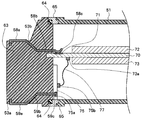
 図1は本発明の第1の実施の形態に係る内視鏡用コネクタを示す斜視図である。図2は図1とは別角度から見た内視鏡用コネクタの構成を示す斜視図である。図3は内視鏡装置の全体構成を示す斜視図である。図4はプロセッサの外観を示す斜視図である。図5は内視鏡コネクタの構成を示す斜視図である。図6は図4中のレセプタクル部41を示す斜視図である。 図7は内視鏡コネクタの断面形状を示す斜視図であり、 図8は内視鏡コネクタの構成を示す断面図である。 FIG. 1 is a perspective view showing an endoscope connector according to a first embodiment of the present invention. FIG. 2 is a perspective view showing the configuration of the endoscope connector as viewed from an angle different from that in FIG. FIG. 3 is a perspective view showing the overall configuration of the endoscope apparatus. FIG. 4 is a perspective view showing the external appearance of the processor. FIG. 5 is a perspective view showing the configuration of the endoscope connector. FIG. 6 is a perspective view showing the receptacle 41 in FIG. FIG. 7 is a perspective view showing the cross-sectional shape of the endoscope connector, and FIG. 8 is a cross-sectional view showing the configuration of the endoscope connector.
 なお、以下の説明において、各実施の形態に基づく図面は、模式的なものであり、各部分の厚みと幅との関係、夫々の部分の厚みの比率などは現実のものとは異なることに留意すべきであり、図面の相互間においても互いの寸法の関係や比率が異なる部分が含まれている場合がある。 In the following description, the drawings based on each embodiment are schematic, and the relationship between the thickness and width of each part, the thickness ratio of each part, and the like are different from the actual ones. It should be noted that the drawings may include portions having different dimensional relationships and ratios between the drawings.
 図3に示すように、内視鏡装置1は、観察対象部位、例えば大腸などの管腔内へ挿入する細長の長尺部材としての挿入部2と、この挿入部2の基端部に連設された操作部3と、この操作部3の側面より延設された複合ケーブルであるユニバーサルケーブル4と、このユニバーサルケーブル4の端部に設けられて光源装置とプロセッサ40である外部機器に着脱自在に接続される内視鏡用コネクタ(以下、単にコネクタともいう)50と、を有している。ただし、光源装置とプロセッサが一体のものであっても良い(図4参照)。 As shown in FIG. 3, the endoscope apparatus 1 includes an insertion portion 2 as an elongated member to be inserted into a site to be observed, for example, a lumen such as the large intestine, and a base end portion of the insertion portion 2. The operation unit 3 provided, the universal cable 4 which is a composite cable extending from the side surface of the operation unit 3, and the external device which is provided at the end of the universal cable 4 and which is the light source device and the processor 40 And an endoscope connector (hereinafter simply referred to as a connector) 50 that is freely connected. However, the light source device and the processor may be integrated (see FIG. 4).
 内視鏡装置1の挿入部2は、先端側にCCDやCMOSセンサ等を用いた撮像部が内蔵された先端部6を有し、この先端部6の後部に湾曲自在な可動部としての湾曲部7が連設されている。さらに、この湾曲部7の後部に軟性の管状の部材より形成される長尺で可撓性を有する可撓管部8が連設されている。この挿入部2の可撓管部8は、基端部が操作部3の折れ止め部9に接続されている。 The insertion portion 2 of the endoscope apparatus 1 has a distal end portion 6 in which an imaging portion using a CCD, a CMOS sensor, or the like is built in on the distal end side, and a bending portion as a movable portion that can be bent at the rear portion of the distal end portion 6. The part 7 is continuously provided. Further, a long and flexible flexible tube portion 8 formed of a soft tubular member is connected to the rear portion of the curved portion 7. The proximal end portion of the flexible tube portion 8 of the insertion portion 2 is connected to the bend preventing portion 9 of the operation portion 3.
 操作部3は、ユーザが使用時に把持する把持部10を備えており、挿入部2内に配設されている処置具チャンネル(図示せず)の基端開口を構成する処置具挿入口11が折れ止め部9と把持部10の連設部分に設けられている。また、操作部3の把持部10には、挿入部2の湾曲部7の湾曲操作を行う、ここでは2つの湾曲操作ノブ15と、これら湾曲操作ノブ15を所望の回転位置で固定するための固定レバー16と、を有する湾曲操作部17が配設されている。さらに、把持部10には、各種内視鏡機能を操作するためのスイッチ類13,14が設けられている。 The operation unit 3 includes a gripping unit 10 that a user grips when in use, and a treatment instrument insertion port 11 that constitutes a proximal end opening of a treatment instrument channel (not shown) disposed in the insertion unit 2. It is provided in the connecting part of the bend preventing part 9 and the grip part 10. In addition, the grip portion 10 of the operation portion 3 performs a bending operation of the bending portion 7 of the insertion portion 2. Here, two bending operation knobs 15 and for fixing these bending operation knobs 15 at a desired rotational position. A bending operation unit 17 having a fixing lever 16 is disposed. Furthermore, the grip unit 10 is provided with switches 13 and 14 for operating various endoscope functions.
 内視鏡装置1のユニバーサルケーブル4は、操作部3、またはコネクタ50と接続された両端部分において、その外周部を被覆するように接続強度を維持して捩れなどによる損傷を防止するための折れ止め部材18,19を有している。ユニバーサルケーブル4の終端の折れ止め部材19に、コネクタ50が取り付けられる。 The universal cable 4 of the endoscope apparatus 1 is folded to prevent damage due to twisting while maintaining the connection strength so as to cover the outer peripheral portion of the operation unit 3 or both ends connected to the connector 50. Stop members 18 and 19 are provided. A connector 50 is attached to the terminal member 19 of the universal cable 4.
 本実施の形態においては、コネクタ50は、図4のプロセッサ40のレセプタクル部41に接続されるようになっており、以下の説明では、コネクタ50については、ユニバーサルケーブル4側を基端側(又は前方側)とし、プロセッサ40に接続される側を先端側(又は後方側)として説明する。 In the present embodiment, the connector 50 is connected to the receptacle 41 of the processor 40 of FIG. 4. In the following description, the universal cable 4 side is the base end side (or the connector 50 side). The description will be made assuming that the side connected to the processor 40 is the front end side (or the rear side).
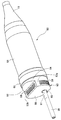
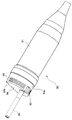
 図1及び図2に示すように、コネクタ50は、先端側に設けられるプラグ部52と基端側に設けられるコネクタケース51とを有する。コネクタケース51は、術者の手で把持が容易な径及びサイズを有する略円筒形状に形成されているが、基端側は折れ止め部材19の外形に合わせるように、前方に向かって径が若干細くなったケース体である。 As shown in FIGS. 1 and 2, the connector 50 includes a plug portion 52 provided on the distal end side and a connector case 51 provided on the proximal end side. The connector case 51 is formed in a substantially cylindrical shape having a diameter and size that can be easily grasped by an operator's hand, but the proximal end has a diameter toward the front so as to match the outer shape of the anti-bending member 19. The case body is slightly thinner.
 プロセッサ40のレセプタクル部41は、コネクタ50のプラグ部52が挿入されて電気的な接続が行われるようになっており、後述するように、プラグ部52の外形状と、レセプタクル部41の内形状とは、略一致するように構成されている。なお、コネクタケース51の円筒形状の中心軸(コネクタ50の中心軸)方向がコネクタ50のレセプタクル部41への挿入方向となる。 The receptacle portion 41 of the processor 40 is electrically connected by inserting the plug portion 52 of the connector 50. As will be described later, the outer shape of the plug portion 52 and the inner shape of the receptacle portion 41 are provided. Is configured to substantially match. The direction of the cylindrical central axis of the connector case 51 (the central axis of the connector 50) is the direction in which the connector 50 is inserted into the receptacle 41.
 プラグ部52は、先端側に導電部を構成する電気接点(コネクタ接点)58,59が設けられる嵌合部53と、基端側にコネクタケース51に接続される接続部54とを有する。嵌合部53と接続部54とは一体形成されており、コネクタケース51の先端側端部及び接続部54の基端側端部にはフランジ部65が形成されている。フランジ部65によって、レセプタクル部41との嵌合状態が維持されるようになっている。 The plug portion 52 has a fitting portion 53 provided with electrical contacts (connector contacts) 58 and 59 constituting a conductive portion on the distal end side, and a connecting portion 54 connected to the connector case 51 on the proximal end side. The fitting portion 53 and the connection portion 54 are integrally formed, and a flange portion 65 is formed at the distal end side end portion of the connector case 51 and the proximal end side end portion of the connection portion 54. The fitting state with the receptacle part 41 is maintained by the flange part 65.
 接続部54は、コネクタケース51との水密構造を容易にするために、基端側が、コネクタケース51の先端側の外周形状と略同一の外周形状を有するように形成され、接続部54とコネクタケース51とは相互に固着されている。例えば、接続部54とコネクタケース51とは、水密保持のためのOリング64(図8参照)を介在させた状態で、内部の所定位置においてネジ等により相互に固着する構造であってもよい。また、例えば、コネクタケース51内に収納した図示しないフレームの先端をネジ等により接続部54に取付け、コネクタケース51の基端側開口から突出したフレームの基端部分に取り付けたネジ等の押圧部材によって、コネクタケース51をOリング64を介して接続部54側に押圧することで、コネクタケース51と接続部54とを水密に連結するようにしてもよい。本実施の形態においては、コネクタケース51と接続部54とを水密に連結する手法については、特に限定されるものではない。 In order to facilitate the watertight structure with the connector case 51, the connection portion 54 is formed so that the proximal end side has substantially the same outer peripheral shape as the outer peripheral shape of the distal end side of the connector case 51. The case 51 is fixed to each other. For example, the connection portion 54 and the connector case 51 may be configured to be fixed to each other with a screw or the like at a predetermined position inside with an O-ring 64 (see FIG. 8) for maintaining watertightness interposed therebetween. . Further, for example, a pressure member such as a screw attached to the base end portion of the frame protruding from the base end side opening of the connector case 51 by attaching the tip of a frame (not shown) housed in the connector case 51 to the connection portion 54 with a screw or the like. Thus, the connector case 51 and the connection portion 54 may be connected in a watertight manner by pressing the connector case 51 toward the connection portion 54 via the O-ring 64. In the present embodiment, the method for watertightly connecting the connector case 51 and the connection portion 54 is not particularly limited.
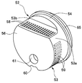
 本実施の形態においては、嵌合部53は、接続部54と同様の円柱形状の一部を切り欠いた形状を有しており、接続部54と同様の周面形状を有する部分(以下、円周部という)53aと、コネクタケース51の円筒形状の中心軸(以下、単に中心軸という)方向に平行な平面部分(以下、平面部という)53bとを有する。嵌合部53の後方側端面は、中心軸に直交する平面(以下、先端面という)56であり、先端面56は、平面部53bを形成することで、円の一部が切り取られた円弧形状になっている。 In the present embodiment, the fitting portion 53 has a shape in which a part of a columnar shape similar to that of the connection portion 54 is cut out, and a portion having a peripheral surface shape similar to that of the connection portion 54 (hereinafter, A circumferential portion 53a and a planar portion 53b parallel to the cylindrical central axis (hereinafter simply referred to as the central axis) direction of the connector case 51; The rear end surface of the fitting portion 53 is a flat surface (hereinafter, referred to as a front end surface) 56 orthogonal to the central axis, and the front end surface 56 forms a flat surface portion 53b so that a circle is partially cut off. It has a shape.
 本実施の形態においては、嵌合部53の円周部53aに電気接点(コネクタ接点)59が設けられ、平面部53bに電気接点(コネクタ接点)58が設けられるようになっている。コネクタ接点59は、円周部53aの周面の一部に、コネクタケース51の中心軸方向に所定の長さを有して複数並設されている。また、コネクタ接点58は、平面部53bの表面の一部に、コネクタケース51の中心軸方向である平面部53bの短手方向に所定の長さを有して、平面部53bの長手方向に複数並設されている。 In this embodiment, an electrical contact (connector contact) 59 is provided on the circumferential portion 53a of the fitting portion 53, and an electrical contact (connector contact) 58 is provided on the flat portion 53b. A plurality of connector contacts 59 are arranged in parallel on a part of the circumferential surface of the circumferential portion 53 a so as to have a predetermined length in the central axis direction of the connector case 51. Further, the connector contact 58 has a predetermined length in a short direction of the flat surface portion 53b that is the central axis direction of the connector case 51 on a part of the surface of the flat surface portion 53b, and extends in the longitudinal direction of the flat surface portion 53b. A plurality are arranged side by side.
 なお、嵌合部53の円周部53aの縁辺には、プロセッサ40に内視鏡装置1を認識させるための切り欠き部60が形成されている。また、プラグ部52の先端面である嵌合部53の先端面56には、開口部61が設けられており、この開口部61には、ライトガイド26が挿通されるようになっている。 Note that a notch 60 is formed on the edge of the circumferential portion 53 a of the fitting portion 53 so that the processor 40 recognizes the endoscope apparatus 1. In addition, an opening 61 is provided in the distal end surface 56 of the fitting portion 53 that is the distal end surface of the plug portion 52, and the light guide 26 is inserted into the opening 61.
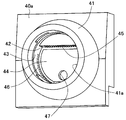
 コネクタ50は、図6に示すプロセッサ40の前面40aに設けられたレセプタクル部41に接続される。コネクタ50を、プロセッサ40のレセプタクル部41の孔部41a内に挿通して嵌合配置することで、コネクタ50とレセプタクル部41との接続状態となる。なお、プロセッサ40の前面40aには、プロセッサ40の操作及びプロセッサ40の状態表示のためのパネル部49が設けられている。 The connector 50 is connected to the receptacle 41 provided on the front surface 40a of the processor 40 shown in FIG. The connector 50 is inserted and inserted into the hole 41 a of the receptacle 41 of the processor 40, thereby connecting the connector 50 and the receptacle 41. A panel unit 49 for operating the processor 40 and displaying the status of the processor 40 is provided on the front surface 40a of the processor 40.
 プロセッサ40のレセプタクル部41は、孔部41aの所定位置に図示しない金属製の装着部が配設されている。この装着部に、コネクタ50のフランジ部65が嵌合固定される。なお、金属からなるフランジ部65および装着部は、互いが嵌合して接触することで、内視鏡装置1およびプロセッサ40のグランド同士を接続する。 The receptacle 41 of the processor 40 is provided with a metal mounting portion (not shown) at a predetermined position of the hole 41a. The flange portion 65 of the connector 50 is fitted and fixed to the mounting portion. The flange portion 65 and the mounting portion made of metal are connected to each other so that the endoscope device 1 and the ground of the processor 40 are connected to each other.
 または、装着部はグランドと接続するための金属部を有していれば良く、非金属部材によって嵌合固定しても良い。 Alternatively, the mounting portion only needs to have a metal portion for connection to the ground, and may be fitted and fixed by a non-metallic member.
 コネクタ50が未接続の状態において、各レセプタクル接点へのユーザの接触を防止するための可動シャッタを有していても良い。 In the state where the connector 50 is not connected, a movable shutter may be provided to prevent the user from contacting each receptacle contact.
 孔部41a内は、コネクタ50の嵌合部53の外形状に略一致する形状を有している。即ち、孔部41a内には、コネクタ50の挿入方向に垂直な面であって嵌合部53の先端面56と形状及びサイズが略同一の平面部44と、嵌合部53の円周部53aの形状及びサイズと略同一の内周面部43と、平面部44に垂直な平面であって嵌合部53の平面部53bと形状及びサイズが略同一の平面部42とを有する。 The inside of the hole portion 41 a has a shape that substantially matches the outer shape of the fitting portion 53 of the connector 50. That is, in the hole portion 41a, a flat surface 44 that is a surface perpendicular to the insertion direction of the connector 50 and has substantially the same shape and size as the distal end surface 56 of the fitting portion 53, and a circumferential portion of the fitting portion 53 The inner peripheral surface portion 43 has substantially the same shape and size as 53a, and the flat portion 42 is a flat surface perpendicular to the flat surface portion 44 and has substantially the same shape and size as the flat surface portion 53b of the fitting portion 53.
 コネクタ50の嵌合部53を孔部41a内に挿入することで、嵌合部53の円周部53a及び平面部53bがそれぞれ内周面部43及び平面部42と対向して、嵌合部53と孔部41aとが嵌合するようになっている。この嵌合状態で、平面部42には、平面部53bに設けた複数のコネクタ接点58にそれぞれ対応する位置に複数の電気接点(以下、レセプタクル接点という)45が設けられており、内周面部43には、円周部53aに設けた複数のコネクタ接点59にそれぞれ対応する位置に複数の電気接点(レセプタクル接点)46が設けられている。これにより、コネクタ50の嵌合部53を孔部41a内に挿入してコネクタ50とレセプタクル部41とを接続することで、各コネクタ接点58と各レセプタクル接点45同士がそれぞれ接触して電気的な接続が行われ、各コネクタ接点59と各レセプタクル接点46同士がそれぞれ接触して電気的な接続が行われる。こうして、内視鏡装置1とプロセッサ40とが各種信号の授受を行なうことができるようになる。 By inserting the fitting portion 53 of the connector 50 into the hole 41a, the circumferential portion 53a and the flat portion 53b of the fitting portion 53 face the inner peripheral surface portion 43 and the flat portion 42, respectively, and the fitting portion 53 is inserted. And the hole 41a are fitted. In this fitted state, the planar portion 42 is provided with a plurality of electrical contacts (hereinafter referred to as receptacle contacts) 45 at positions corresponding to the plurality of connector contacts 58 provided on the planar portion 53b. 43, a plurality of electrical contacts (receptacle contacts) 46 are provided at positions corresponding to the plurality of connector contacts 59 provided on the circumferential portion 53a. As a result, by inserting the fitting portion 53 of the connector 50 into the hole portion 41a and connecting the connector 50 and the receptacle portion 41, each connector contact 58 and each receptacle contact 45 are brought into contact with each other and are electrically connected. Connection is made, and each connector contact 59 and each receptacle contact 46 come into contact with each other to make electrical connection. Thus, the endoscope apparatus 1 and the processor 40 can exchange various signals.
 なお、コネクタ50がレセプタクル部41に接続された状態において、コネクタ50の開口部61から突出したライトガイド26は、平面部44に設けられた開口部47内に挿入されるようになっている。これにより、プロセッサ40内のハロゲンランプなどの照明光源から伝送された照明光をライトガイド26を介して内視鏡装置1内に導光することが可能な状態となる。 In the state where the connector 50 is connected to the receptacle 41, the light guide 26 protruding from the opening 61 of the connector 50 is inserted into the opening 47 provided in the flat portion 44. As a result, the illumination light transmitted from the illumination light source such as a halogen lamp in the processor 40 can be guided into the endoscope apparatus 1 through the light guide 26.
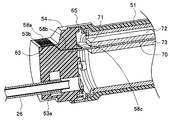
 次に、図7及び図8を参照して嵌合部53のコネクタ接点58,59と回路基板70との電気的な接続について説明する。 Next, electrical connection between the connector contacts 58 and 59 of the fitting portion 53 and the circuit board 70 will be described with reference to FIGS.
 嵌合部53の内部にはコネクタ接点58,59及びライトガイド26が配設されている。嵌合部53内部は、コネクタ接点58,59及びライトガイド26を挿通する部分を除く大部分に樹脂63が充填されている。樹脂63によって各コネクタ接点58,59の配置が固定されていると共に、各コネクタ接点58,59同士が互いに絶縁された状態となっている。 The connector contacts 58 and 59 and the light guide 26 are disposed inside the fitting portion 53. The inside of the fitting part 53 is filled with resin 63 in most parts except for the part through which the connector contacts 58 and 59 and the light guide 26 are inserted. The arrangement of the connector contacts 58 and 59 is fixed by the resin 63, and the connector contacts 58 and 59 are insulated from each other.
 コネクタケース51側には、回路基板70が、中心軸に沿って、図示しない支持部材に支持されて配置されている。樹脂63の所定位置には、回路基板70の厚みに対応する間隔で平面部53bに平行な対向面を有する凹部が設けられており、この凹部に回路基板70の先端側が嵌入されるようになっている。即ち、回路基板70の基板表面は、平面部53bに平行である。回路基板70の先端側の表面上に、各コネクタ接点58に対応する基板端子71が設けられている。 On the connector case 51 side, a circuit board 70 is arranged along a central axis and supported by a support member (not shown). At a predetermined position of the resin 63, a recess having an opposing surface parallel to the flat portion 53b is provided at an interval corresponding to the thickness of the circuit board 70, and the front end side of the circuit board 70 is fitted into the recess. ing. That is, the substrate surface of the circuit board 70 is parallel to the flat portion 53b. A board terminal 71 corresponding to each connector contact 58 is provided on the front surface of the circuit board 70.
 回路基板70の基板端子71形成側の表面上には、複数の回路部品からなる回路部72が配設されている。また、回路基板70の基板端子71形成側の反対側の表面上には、複数の回路部品からなる回路部73が配設されている。本実施の形態においては、回路部72は、例えば映像信号等の伝送に適した高速伝送用の回路部であり、回路部73は、高速伝送用以外の回路部である。また、高速伝送用の回路部と高速伝送用以外の回路部は、基板上に配置されていれば良く上記の配置以外であっても良い。 On the surface of the circuit board 70 on the side where the board terminals 71 are formed, a circuit portion 72 made up of a plurality of circuit components is disposed. A circuit portion 73 made up of a plurality of circuit components is disposed on the surface of the circuit board 70 opposite to the board terminal 71 formation side. In the present embodiment, the circuit unit 72 is a circuit unit for high-speed transmission suitable for transmission of, for example, a video signal, and the circuit unit 73 is a circuit unit other than for high-speed transmission. Further, the circuit unit for high-speed transmission and the circuit unit other than for high-speed transmission may be arranged on the substrate and may be arranged other than the above arrangement.
 コネクタ接点58は、金属の例えば細長く幅が一定の板上部材を長手方向には所定の形状に屈曲させることで形成されており、平面部53bにおいて外部に露出した直線状の接点部58aと、回路基板70の位置(平面部53bと基板70平面との距離)に応じて屈曲した導通部58bと、回路基板70の基板端子71に接触する接触部58cとを有する。 The connector contact 58 is formed by bending, for example, a metal plate-like member having a long and constant width into a predetermined shape in the longitudinal direction, and a linear contact portion 58a exposed to the outside in the plane portion 53b. The conductive portion 58b is bent according to the position of the circuit board 70 (the distance between the flat portion 53b and the plane of the substrate 70), and the contact portion 58c is in contact with the board terminal 71 of the circuit board 70.
 本実施の形態においては、各コネクタ接点58はいずれも同一形状であり、各コネクタ接点58同士は平行で且つ同一間隔に配置される。また、各コネクタ接点58の長手方向は中心軸方向に一致させている。本実施の形態においては、基板端子71は、回路基板70を樹脂63に嵌入した状態で、平面部53b上の接点部58aの配列方向に平行な方向に配列されており、各基板端子71同士の間隔は、各コネクタ接点58同士の間隔と同一である。 In the present embodiment, the connector contacts 58 have the same shape, and the connector contacts 58 are arranged in parallel and at the same interval. Further, the longitudinal direction of each connector contact 58 coincides with the central axis direction. In the present embodiment, the substrate terminals 71 are arranged in a direction parallel to the arrangement direction of the contact portions 58a on the flat surface portion 53b in a state where the circuit board 70 is fitted in the resin 63. Is the same as the interval between the connector contacts 58.
 これにより、回路基板70を樹脂63に嵌入した状態では、各コネクタ接点58の接触部58cが各基板端子71にそれぞれ接触するように構成することができる。この場合には、各コネクタ接点58の接点部58aと対応する基板端子71との間の距離は、いずれのコネクタ接点58についても同一であり、また、各コネクタ接点58の形状及びサイズが同一であるので、各接点部58aと対応する基板端子71との間のインピーダンスは、いずれのコネクタ接点58についても同一である。 Thereby, when the circuit board 70 is fitted in the resin 63, the contact portions 58c of the connector contacts 58 can be configured to contact the board terminals 71, respectively. In this case, the distance between the contact portion 58a of each connector contact 58 and the corresponding board terminal 71 is the same for any connector contact 58, and the shape and size of each connector contact 58 are the same. Therefore, the impedance between each contact portion 58 a and the corresponding board terminal 71 is the same for any connector contact 58.
 従って、本実施の形態においては、各コネクタ接点58による伝送特性は、相互に同一である。各コネクタ接点58は、電気的な特性に優れた材料により形成されて、基板端子71に直接接続されており、各コネクタ接点58と各基板端子71との間の接続に他の配線材料等を用いる必要がないことから、コネクタ接点58による信号の伝送は、極めて伝送特性に優れており、高速伝送が可能である。例えば、本実施の形態においては、コネクタ接点58は、映像信号の伝送用に用いられる。 Therefore, in the present embodiment, the transmission characteristics of each connector contact 58 are the same. Each connector contact 58 is formed of a material having excellent electrical characteristics and is directly connected to the board terminal 71, and other wiring material or the like is used for connection between each connector contact 58 and each board terminal 71. Since there is no need to use it, signal transmission through the connector contact 58 is extremely excellent in transmission characteristics, and high-speed transmission is possible. For example, in the present embodiment, the connector contact 58 is used for transmitting a video signal.
 挿入部2先端の撮像部によって得られた映像信号は、挿入部2、操作部3及びユニバーサルケーブル4を介してコネクタ50のコネクタケース51内の回路基板70に搭載された回路部72に伝送される。コネクタ50をレセプタクル部41に接続することで、コネクタ接点58とレセプタクル接点45とが接続され、回路部72は、映像信号を基板端子71からコネクタ接点58及びレセプタクル接点45を介してプロセッサ40の回路部に伝送する。基板端子71とコネクタ接点58との伝送特性が良好であることから、回路部72は、外部機器であるプロセッサ40との間で高速伝送が可能であり、高解像度の映像信号等を伝送エラーなく伝送することが可能である。 The video signal obtained by the imaging unit at the tip of the insertion unit 2 is transmitted to the circuit unit 72 mounted on the circuit board 70 in the connector case 51 of the connector 50 via the insertion unit 2, the operation unit 3, and the universal cable 4. The By connecting the connector 50 to the receptacle part 41, the connector contact 58 and the receptacle contact 45 are connected, and the circuit part 72 transmits the video signal from the board terminal 71 to the circuit of the processor 40 via the connector contact 58 and the receptacle contact 45. Transmitted to the department. Since the transmission characteristics between the board terminal 71 and the connector contact 58 are good, the circuit unit 72 can perform high-speed transmission with the processor 40, which is an external device, and can transmit a high-resolution video signal or the like without transmission errors. It is possible to transmit.
 一方、コネクタ接点59は、高速伝送用途以外の用途で用いられる。例えば、コネクタ接点59は、電力の伝送用及び制御や情報伝送のために用いられる。コネクタ接点59は、金属の例えば細長く幅が一定の板上部材を長手方向には所定の形状に屈曲させることで形成されており、円周部53aにおいて外部に露出した直線状の接点部59aと、伝送用基板75の端子75aの位置に応じて屈曲した導通部59bと、伝送用基板75の端子75aに接触する接触部59cとを有する。基板75には各端子75aに接続されたコネクタ75bが設けられており、このコネクタ75bは、ケーブル77を介して回路基板70に設けたコネクタ73aに接続されるようになっている。こうして、回路基板70に搭載された回路部73の各回路と、各コネクタ接点59との導通が図られる。 On the other hand, the connector contact 59 is used for purposes other than high-speed transmission. For example, the connector contact 59 is used for power transmission, control, and information transmission. The connector contact 59 is formed by bending, for example, a thin plate-like member made of metal, for example, into a predetermined shape in the longitudinal direction, and a linear contact portion 59a exposed to the outside at the circumferential portion 53a. The conductive portion 59b is bent according to the position of the terminal 75a of the transmission board 75, and the contact portion 59c is in contact with the terminal 75a of the transmission board 75. A connector 75 b connected to each terminal 75 a is provided on the substrate 75, and this connector 75 b is connected to a connector 73 a provided on the circuit substrate 70 via a cable 77. In this way, conduction between each circuit of the circuit unit 73 mounted on the circuit board 70 and each connector contact 59 is achieved.
 なお、図8の例では、コネクタ接点59は、基板75を介して回路基板70のコネクタ73aに接続される例を示しているが、各コネクタ接点59を直接回路基板70上の端子に接続するようにしてもよい。また、図8の例では、全てのコネクタ接点59が回路基板70のコネクタ73aに接続される例を示したが、コネクタ接点59の一部又は全部が、内視鏡装置1内の回路基板70以外の他の回路部に接続されるようにしてもよい。 8 shows an example in which the connector contact 59 is connected to the connector 73a of the circuit board 70 via the board 75, but each connector contact 59 is directly connected to a terminal on the circuit board 70. You may do it. 8 shows an example in which all connector contacts 59 are connected to the connector 73a of the circuit board 70. However, part or all of the connector contacts 59 may be connected to the circuit board 70 in the endoscope apparatus 1. You may make it connect to other circuit parts other than.
 このように本実施の形態においては、嵌合部において円筒形状の一部を切り欠いた形状に形成される平面部を設け、この平面部上にコネクタ接点をコネクタの中心軸に垂直な方向に配列する。そして、このコネクタ接点の配列方向に平行な方向に基板端子が設けられた基板を中心軸に平行な方向に配置し、コネクタ接点の外部機器との接触部から基板端子までの距離を全てのコネクタ接点について同一にする。これにより、コネクタ接点を直接基板端子に接続可能にすると共に、接触部から基板端子までのインピーダンスを全てのコネクタ接点について同一にすることで、伝送特性を向上させて、高速伝送を可能にしている。こうして、本実施の形態におけるコネクタを採用することで、高解像度の映像信号を伝送エラー無く伝送することが可能となる。また、本実施の形態においては、平面部だけでは配置できないコネクタ接点を嵌合部の円周部を利用して配置しており、このコネクタ接点を高速伝送が必要でない伝送用として用いることで、嵌合部の周面を有効に利用して、十分な数のコネクタ接点を配置することを可能にしている。 As described above, in the present embodiment, the fitting portion is provided with a flat portion formed in a shape obtained by cutting out a part of the cylindrical shape, and the connector contact is provided on the flat portion in a direction perpendicular to the central axis of the connector. Arrange. Then, the board provided with the board terminals in the direction parallel to the connector contact arrangement direction is arranged in the direction parallel to the central axis, and the distance from the contact part of the connector contact with the external device to the board terminal is determined for all connectors. Make contacts identical. As a result, the connector contact can be directly connected to the board terminal, and the impedance from the contact portion to the board terminal is made the same for all connector contacts, thereby improving the transmission characteristics and enabling high-speed transmission. . In this way, by employing the connector in this embodiment, it becomes possible to transmit a high-resolution video signal without transmission errors. Further, in the present embodiment, the connector contact that cannot be arranged only by the plane portion is arranged using the circumferential portion of the fitting portion, and by using this connector contact for transmission that does not require high-speed transmission, It is possible to arrange a sufficient number of connector contacts by effectively using the peripheral surface of the fitting portion.
 なお、本実施の形態においては、嵌合部の円筒形状の一部を切り欠いた形状の1つの平面部を形成する例を示したが、円筒形状の複数カ所を切り欠いた形状の2つ以上の平面部を形成するようにしてもよい。この場合には、各平面部に対応した回路基板を用意することで、これらの回路基板において高速伝送が可能となる。 In the present embodiment, an example is shown in which one planar portion having a shape in which a part of the cylindrical shape of the fitting portion is cut out is shown, but two shapes in which a plurality of cylindrical shapes are cut out are shown. You may make it form the above plane part. In this case, by preparing a circuit board corresponding to each planar portion, high-speed transmission is possible on these circuit boards.
 また、回路基板において高速伝送を可能にするためには、各コネクタ接点を直接回路基板の基板端子に接続すると共に、各コネクタ接点の外部機器との接触部から基板端子までのインピーダンスを全てのコネクタ接点において共通にすればよい。回路基板が平面であることを考慮すると、各コネクタ接点の配列方向と基板端子の配列方向とが平行であればよいと考えられる。従って、上記実施の形態においては、平面部は、中心軸に平行な面を有しているものとして説明したが、多少中心軸から傾斜していてもよい。更に、各コネクタ接点によるインピーダンスを一致させればよいので、配線パターンを変更することで、多少コネクタ接点同士の配置を平行にしなくてもよい場合や間隔を均一にしなくてもよい場合が考えられる。 In addition, in order to enable high-speed transmission on the circuit board, each connector contact is directly connected to the board terminal of the circuit board, and the impedance from the contact portion of each connector contact with the external device to the board terminal is set for all connectors. What is necessary is just to make it common in a contact. Considering that the circuit board is flat, it is considered that the arrangement direction of the connector contacts and the arrangement direction of the board terminals may be parallel. Therefore, in the above-described embodiment, the planar portion has been described as having a surface parallel to the central axis, but may be slightly inclined from the central axis. Furthermore, it is only necessary to match the impedances of the respective connector contacts. Therefore, by changing the wiring pattern, there may be cases where the arrangement of the connector contacts does not have to be somewhat parallel or the intervals need not be uniform. .
 以上の実施の形態に記載した発明は、その実施の形態、および変形例に限ることなく、その他、実施段階ではその要旨を逸脱しない範囲で種々の変形を実施し得ることが可能である。さらに、上記実施の形態には、種々の段階の発明が含まれており、開示される複数の構成要件における適宜な組合せにより種々の発明が抽出され得るものである。 The invention described in the above embodiment is not limited to the embodiment and modification examples, and various modifications can be made without departing from the scope of the invention in the implementation stage. Further, the above embodiments include inventions at various stages, and various inventions can be extracted by appropriately combining a plurality of disclosed constituent elements.
 例えば、実施の形態に示される全構成要件から幾つかの構成要件が削除されても、述べられている課題が解決でき、述べられている効果が得られる場合には、この構成要件が削除された構成が発明として抽出され得るものである。 For example, even if some constituent requirements are deleted from all the constituent requirements shown in the embodiment, the described requirements can be deleted if the stated problem can be solved and the stated effect can be obtained. The configuration can be extracted as an invention.
 本発明によれば、レセプタクルとの嵌合部において平面部を設けてこの平面部にコネクタ接点を配置することにより、コネクタ接点と基板端子とを直接接続することを可能にして伝送特性を向上させることができるという効果を有する。 According to the present invention, by providing a flat portion in the fitting portion with the receptacle and arranging the connector contact on the flat portion, it is possible to directly connect the connector contact and the board terminal, thereby improving the transmission characteristics. It has the effect of being able to.
 本発明は、上述した実施の形態に限定されるものではなく、本発明の要旨を変えない範囲において、種々の変更、改変等が可能である。 The present invention is not limited to the above-described embodiments, and various changes and modifications can be made without departing from the scope of the present invention.
 本出願は、2015年6月3日に日本国に出願された特願2015-113344号を優先権主張の基礎として出願するものであり、上記の開示内容は、本願明細書、請求の範囲に引用されるものとする。 This application is filed on the basis of the priority claim of Japanese Patent Application No. 2015-113344 filed in Japan on June 3, 2015. The above disclosure is included in the present specification and claims. Shall be quoted.

Claims (5)

  1.  円筒形状を有し、被検体を観察するための内視鏡と前記観察された情報を処理する外部機器との間を電気的に接続するための嵌合部と、
     前記嵌合部の前記円筒形状の少なくとも1部に対して設けられた平面部と、
     前記平面部において電気的に導通可能に設けられ、前記外部機器と通信するための導電部と、を有することを特徴とする内視鏡用コネクタ。
    A fitting portion for electrically connecting between an endoscope for observing a subject and an external device for processing the observed information having a cylindrical shape;
    A plane portion provided for at least one portion of the cylindrical shape of the fitting portion;
    An endoscope connector comprising: a conductive portion that is provided in the plane portion so as to be electrically conductive and communicates with the external device.
  2.  前記導電部は、前記外部機器と電気的に導通可能な複数の電気接点を有し、
     前記複数の電気接点は、前記嵌合部近傍に設けられ前記外部機器と通信するための基板に設けられた複数の基板端子に電気的に接続され、
     前記導電部は、前記複数の電気接点から前記複数の基板端子までのインピーダンスが前記複数の電気接点相互間で同一である
     ことを特徴とする請求項1に記載の内視鏡用コネクタ。
    The conductive portion has a plurality of electrical contacts that can be electrically connected to the external device,
    The plurality of electrical contacts are electrically connected to a plurality of substrate terminals provided in the vicinity of the fitting portion and provided on a substrate for communicating with the external device,
    The endoscope connector according to claim 1, wherein the conductive portion has the same impedance from the plurality of electrical contacts to the plurality of substrate terminals between the plurality of electrical contacts.
  3.  前記複数の電気接点は、相互に同一形状を有し、
     前記導電部は、前記複数の基板端子と前記複数の電気接点とがそれぞれ等距離で各々が接続される
     ことを特徴とする請求項1に記載の内視鏡用コネクタ。
    The plurality of electrical contacts have the same shape as each other,
    The endoscope connector according to claim 1, wherein the plurality of board terminals and the plurality of electrical contacts are respectively connected at equal distances in the conductive portion.
  4.  前記複数の電気接点の配列方向は、前記複数の基板端子の配列方向に平行である
     ことを特徴とする請求項1に記載の内視鏡用コネクタ。
    The endoscope connector according to claim 1, wherein an arrangement direction of the plurality of electrical contacts is parallel to an arrangement direction of the plurality of board terminals.
  5.  さらに、前記嵌合部の側面のうち前記平面部以外の円筒形状の側面に設けられる第2の導電部、を有し、
     前記第2の導電部は、前記基板又は内視鏡内の所定の素子のうち少なくとも一方に接続され、
     前記基板上の前記基板端子に接続された回路素子は、前記少なくとも一方と前記第2の導電部との間の通信速度よりも速い通信速度で前記外部機器との通信を行う
     ことを特徴とする請求項1に記載の内視鏡用コネクタ。
    Furthermore, it has a second conductive portion provided on a cylindrical side surface other than the flat surface portion of the side surface of the fitting portion,
    The second conductive portion is connected to at least one of the predetermined elements in the substrate or the endoscope,
    The circuit element connected to the substrate terminal on the substrate communicates with the external device at a communication speed faster than a communication speed between the at least one and the second conductive portion. The endoscope connector according to claim 1.
PCT/JP2016/061814 2015-06-03 2016-04-12 Connector for endoscope WO2016194485A1 (en)

Priority Applications (4)

Application Number Priority Date Filing Date Title
JP2016554751A JP6072389B1 (en) 2015-06-03 2016-04-12 Endoscope connector
EP16802922.1A EP3184028A4 (en) 2015-06-03 2016-04-12 Connector for endoscope
CN201680002655.XA CN107072519A (en) 2015-06-03 2016-04-12 Endoscope-use connector
US15/485,463 US10624528B2 (en) 2015-06-03 2017-04-12 Connector

Applications Claiming Priority (2)

Application Number Priority Date Filing Date Title
JP2015-113344 2015-06-03
JP2015113344 2015-06-03

Related Child Applications (1)

Application Number Title Priority Date Filing Date
US15/485,463 Continuation US10624528B2 (en) 2015-06-03 2017-04-12 Connector

Publications (1)

Publication Number Publication Date
WO2016194485A1 true WO2016194485A1 (en) 2016-12-08

Family

ID=57440870

Family Applications (1)

Application Number Title Priority Date Filing Date
PCT/JP2016/061814 WO2016194485A1 (en) 2015-06-03 2016-04-12 Connector for endoscope

Country Status (5)

Country Link
US (1) US10624528B2 (en)
EP (1) EP3184028A4 (en)
JP (1) JP6072389B1 (en)
CN (1) CN107072519A (en)
WO (1) WO2016194485A1 (en)

Families Citing this family (4)

* Cited by examiner, † Cited by third party
Publication number Priority date Publication date Assignee Title
US10916903B2 (en) * 2018-02-04 2021-02-09 Creganna Unlimited Company System having a cable assembly and plug and receptacle connectors
CN110367910A (en) * 2019-08-23 2019-10-25 重庆金山科技(集团)有限公司 Endoscopy joints, endoscope mirror body, cold light source for endoscope and endoscopic system
DE102021123315A1 (en) 2021-09-09 2023-03-09 Karl Storz Se & Co. Kg Connection adapter receptacle for a light source for transmitting video signals from a video endoscope to a video processor that can be connected to the light source, connection adapter for a video endoscope, light source, video endoscope, video processor and video endoscope system
US11883002B2 (en) 2021-09-09 2024-01-30 Karl Storz Se & Co. Kg Endoscope connector and endoscope adapter

Citations (2)

* Cited by examiner, † Cited by third party
Publication number Priority date Publication date Assignee Title
JPH06251829A (en) * 1993-02-24 1994-09-09 Olympus Optical Co Ltd Connector device
JPH06250103A (en) * 1993-02-24 1994-09-09 Olympus Optical Co Ltd Connector device

Family Cites Families (25)

* Cited by examiner, † Cited by third party
Publication number Priority date Publication date Assignee Title
JPS5578932A (en) * 1978-12-08 1980-06-14 Olympus Optical Co Connector for light guide cable of endoscope
JPS5670747A (en) * 1979-11-15 1981-06-12 Olympus Optical Co Eyepiece apparatus of endoscope
JP2572394B2 (en) * 1987-03-19 1997-01-16 オリンパス光学工業株式会社 Electronic endoscope
US5469841A (en) * 1992-10-29 1995-11-28 Olympus Optical Co., Ltd. Endoscope apparatus provided with liquid removing mechanism for the electric connector
US5810620A (en) * 1992-10-29 1998-09-22 Olympus Optical Co., Ltd. Electric connector provided with a shielding part for electrical contacts at the distal end of the plug
JP3245461B2 (en) * 1992-10-29 2002-01-15 オリンパス光学工業株式会社 Endoscope device
JPH07184857A (en) * 1993-12-28 1995-07-25 Olympus Optical Co Ltd Endoscope system
US5564951A (en) * 1994-02-23 1996-10-15 Baxter International Inc. Electrical cable connector and method of making
US5865726A (en) * 1996-03-27 1999-02-02 Asahi Kogaku Kogyo Kabushiki Kaisha Front end structure of side-view type endoscope
US6211904B1 (en) * 1997-09-11 2001-04-03 Edwin L. Adair Surgical devices incorporating reduced area imaging devices
US6043839A (en) * 1997-10-06 2000-03-28 Adair; Edwin L. Reduced area imaging devices
US6982740B2 (en) * 1997-11-24 2006-01-03 Micro-Medical Devices, Inc. Reduced area imaging devices utilizing selected charge integration periods
US20020098732A1 (en) * 2001-01-19 2002-07-25 Olympus Optical Co., Ltd. Connector device for an endoscope
US7549958B2 (en) * 2004-02-09 2009-06-23 Olympus Corporation Endoscope apparatus
JP4987257B2 (en) * 2005-06-29 2012-07-25 オリンパス株式会社 Endoscope
JP4762828B2 (en) * 2006-08-22 2011-08-31 モレックス インコーポレイテド Watertight connector and manufacturing method thereof
JP5178239B2 (en) * 2008-02-27 2013-04-10 オリンパスメディカルシステムズ株式会社 Medical system
US7632126B1 (en) * 2008-05-23 2009-12-15 Tyco Electronics Corporation High density circular interconnect with bayonet action
US9642513B2 (en) * 2009-06-18 2017-05-09 Endochoice Inc. Compact multi-viewing element endoscope system
JP4960533B2 (en) 2009-10-28 2012-06-27 オリンパスメディカルシステムズ株式会社 Connector for medical equipment
WO2011114957A1 (en) * 2010-03-16 2011-09-22 オリンパスメディカルシステムズ株式会社 Connector system
JPWO2011114771A1 (en) * 2010-03-16 2013-06-27 オリンパスメディカルシステムズ株式会社 Connector connection system
TW201201641A (en) * 2010-06-18 2012-01-01 Sun Wei Ren Micro sensor
JP2015181096A (en) * 2014-03-04 2015-10-15 ソニー・オリンパスメディカルソリューションズ株式会社 Wiring connection device, camera head and endoscope system
JP6153695B1 (en) * 2015-11-19 2017-06-28 オリンパス株式会社 Endoscope device and light source device

Patent Citations (2)

* Cited by examiner, † Cited by third party
Publication number Priority date Publication date Assignee Title
JPH06251829A (en) * 1993-02-24 1994-09-09 Olympus Optical Co Ltd Connector device
JPH06250103A (en) * 1993-02-24 1994-09-09 Olympus Optical Co Ltd Connector device

Non-Patent Citations (1)

* Cited by examiner, † Cited by third party
Title
See also references of EP3184028A4 *

Also Published As

Publication number Publication date
EP3184028A4 (en) 2018-05-16
EP3184028A1 (en) 2017-06-28
JP6072389B1 (en) 2017-02-01
JPWO2016194485A1 (en) 2017-06-22
US20170215702A1 (en) 2017-08-03
US10624528B2 (en) 2020-04-21
CN107072519A (en) 2017-08-18

Similar Documents

Publication Publication Date Title
JP4916595B2 (en) Imaging unit
JP5469867B2 (en) Endoscope with imaging catheter assembly and method for constructing an endoscope
JP5435957B2 (en) Endoscope
CN106886089B (en) Endoscope with a detachable handle
JP6072389B1 (en) Endoscope connector
JP2001095747A (en) Electronic endoscope
JP6109079B2 (en) Cable connection structure and imaging device
US20160331214A1 (en) Endoscope
JP2010012079A (en) Endoscope
US9339168B2 (en) Endoscope operation portion structure
CN110545708B (en) Endoscope bending portion and endoscope
JP2000139927A (en) Ultrasonic endoscope device
US20230000320A1 (en) Endoscope processor and endoscope system
JP4017925B2 (en) Ultrasound endoscope
CN107115088B (en) Endoscope with a detachable handle
US20210290041A1 (en) Distal end portion of endoscope and endoscope
US20130253271A1 (en) Endoscope
JP2015039550A (en) Endoscope
JP3902267B2 (en) Endoscope
JP4493234B2 (en) Endoscope insertion shape detection probe
JP5090044B2 (en) Ultrasonic medical device connector
WO2019039384A1 (en) Ultrasound endoscope
WO2019069608A1 (en) Endoscope
JP2001161642A (en) Connector for endoscope
US11690503B2 (en) Endoscopic instrument

Legal Events

Date Code Title Description
ENP Entry into the national phase

Ref document number: 2016554751

Country of ref document: JP

Kind code of ref document: A

121 Ep: the epo has been informed by wipo that ep was designated in this application

Ref document number: 16802922

Country of ref document: EP

Kind code of ref document: A1

REEP Request for entry into the european phase

Ref document number: 2016802922

Country of ref document: EP

WWE Wipo information: entry into national phase

Ref document number: 2016802922

Country of ref document: EP

NENP Non-entry into the national phase

Ref country code: DE