WO2016143130A1 - Air conditioner connection system - Google Patents
Air conditioner connection system Download PDFInfo
- Publication number
- WO2016143130A1 WO2016143130A1 PCT/JP2015/057350 JP2015057350W WO2016143130A1 WO 2016143130 A1 WO2016143130 A1 WO 2016143130A1 JP 2015057350 W JP2015057350 W JP 2015057350W WO 2016143130 A1 WO2016143130 A1 WO 2016143130A1
- Authority
- WO
- WIPO (PCT)
- Prior art keywords
- air conditioner
- plc
- authentication
- authentication process
- unit
- Prior art date
Links
Images


Classifications
-
- G—PHYSICS
- G06—COMPUTING; CALCULATING OR COUNTING
- G06F—ELECTRIC DIGITAL DATA PROCESSING
- G06F21/00—Security arrangements for protecting computers, components thereof, programs or data against unauthorised activity
- G06F21/30—Authentication, i.e. establishing the identity or authorisation of security principals
- G06F21/305—Authentication, i.e. establishing the identity or authorisation of security principals by remotely controlling device operation
-
- F—MECHANICAL ENGINEERING; LIGHTING; HEATING; WEAPONS; BLASTING
- F24—HEATING; RANGES; VENTILATING
- F24F—AIR-CONDITIONING; AIR-HUMIDIFICATION; VENTILATION; USE OF AIR CURRENTS FOR SCREENING
- F24F11/00—Control or safety arrangements
- F24F11/30—Control or safety arrangements for purposes related to the operation of the system, e.g. for safety or monitoring
-
- F—MECHANICAL ENGINEERING; LIGHTING; HEATING; WEAPONS; BLASTING
- F24—HEATING; RANGES; VENTILATING
- F24F—AIR-CONDITIONING; AIR-HUMIDIFICATION; VENTILATION; USE OF AIR CURRENTS FOR SCREENING
- F24F11/00—Control or safety arrangements
- F24F11/50—Control or safety arrangements characterised by user interfaces or communication
- F24F11/52—Indication arrangements, e.g. displays
-
- F—MECHANICAL ENGINEERING; LIGHTING; HEATING; WEAPONS; BLASTING
- F24—HEATING; RANGES; VENTILATING
- F24F—AIR-CONDITIONING; AIR-HUMIDIFICATION; VENTILATION; USE OF AIR CURRENTS FOR SCREENING
- F24F11/00—Control or safety arrangements
- F24F11/50—Control or safety arrangements characterised by user interfaces or communication
- F24F11/56—Remote control
- F24F11/58—Remote control using Internet communication
-
- F—MECHANICAL ENGINEERING; LIGHTING; HEATING; WEAPONS; BLASTING
- F24—HEATING; RANGES; VENTILATING
- F24F—AIR-CONDITIONING; AIR-HUMIDIFICATION; VENTILATION; USE OF AIR CURRENTS FOR SCREENING
- F24F11/00—Control or safety arrangements
- F24F11/62—Control or safety arrangements characterised by the type of control or by internal processing, e.g. using fuzzy logic, adaptive control or estimation of values
-
- G—PHYSICS
- G06—COMPUTING; CALCULATING OR COUNTING
- G06F—ELECTRIC DIGITAL DATA PROCESSING
- G06F21/00—Security arrangements for protecting computers, components thereof, programs or data against unauthorised activity
- G06F21/30—Authentication, i.e. establishing the identity or authorisation of security principals
- G06F21/44—Program or device authentication
-
- G—PHYSICS
- G08—SIGNALLING
- G08C—TRANSMISSION SYSTEMS FOR MEASURED VALUES, CONTROL OR SIMILAR SIGNALS
- G08C17/00—Arrangements for transmitting signals characterised by the use of a wireless electrical link
- G08C17/02—Arrangements for transmitting signals characterised by the use of a wireless electrical link using a radio link
-
- H—ELECTRICITY
- H04—ELECTRIC COMMUNICATION TECHNIQUE
- H04B—TRANSMISSION
- H04B3/00—Line transmission systems
- H04B3/54—Systems for transmission via power distribution lines
-
- H—ELECTRICITY
- H04—ELECTRIC COMMUNICATION TECHNIQUE
- H04L—TRANSMISSION OF DIGITAL INFORMATION, e.g. TELEGRAPHIC COMMUNICATION
- H04L12/00—Data switching networks
- H04L12/28—Data switching networks characterised by path configuration, e.g. LAN [Local Area Networks] or WAN [Wide Area Networks]
- H04L12/2803—Home automation networks
- H04L12/2807—Exchanging configuration information on appliance services in a home automation network
- H04L12/281—Exchanging configuration information on appliance services in a home automation network indicating a format for calling an appliance service function in a home automation network
-
- H—ELECTRICITY
- H04—ELECTRIC COMMUNICATION TECHNIQUE
- H04L—TRANSMISSION OF DIGITAL INFORMATION, e.g. TELEGRAPHIC COMMUNICATION
- H04L9/00—Cryptographic mechanisms or cryptographic arrangements for secret or secure communications; Network security protocols
- H04L9/08—Key distribution or management, e.g. generation, sharing or updating, of cryptographic keys or passwords
- H04L9/0816—Key establishment, i.e. cryptographic processes or cryptographic protocols whereby a shared secret becomes available to two or more parties, for subsequent use
- H04L9/0819—Key transport or distribution, i.e. key establishment techniques where one party creates or otherwise obtains a secret value, and securely transfers it to the other(s)
- H04L9/0822—Key transport or distribution, i.e. key establishment techniques where one party creates or otherwise obtains a secret value, and securely transfers it to the other(s) using key encryption key
-
- F—MECHANICAL ENGINEERING; LIGHTING; HEATING; WEAPONS; BLASTING
- F24—HEATING; RANGES; VENTILATING
- F24F—AIR-CONDITIONING; AIR-HUMIDIFICATION; VENTILATION; USE OF AIR CURRENTS FOR SCREENING
- F24F11/00—Control or safety arrangements
- F24F11/50—Control or safety arrangements characterised by user interfaces or communication
- F24F11/54—Control or safety arrangements characterised by user interfaces or communication using one central controller connected to several sub-controllers
-
- F—MECHANICAL ENGINEERING; LIGHTING; HEATING; WEAPONS; BLASTING
- F24—HEATING; RANGES; VENTILATING
- F24F—AIR-CONDITIONING; AIR-HUMIDIFICATION; VENTILATION; USE OF AIR CURRENTS FOR SCREENING
- F24F11/00—Control or safety arrangements
- F24F11/50—Control or safety arrangements characterised by user interfaces or communication
- F24F11/56—Remote control
-
- H—ELECTRICITY
- H04—ELECTRIC COMMUNICATION TECHNIQUE
- H04B—TRANSMISSION
- H04B2203/00—Indexing scheme relating to line transmission systems
- H04B2203/54—Aspects of powerline communications not already covered by H04B3/54 and its subgroups
- H04B2203/5429—Applications for powerline communications
- H04B2203/5441—Wireless systems or telephone
-
- Y—GENERAL TAGGING OF NEW TECHNOLOGICAL DEVELOPMENTS; GENERAL TAGGING OF CROSS-SECTIONAL TECHNOLOGIES SPANNING OVER SEVERAL SECTIONS OF THE IPC; TECHNICAL SUBJECTS COVERED BY FORMER USPC CROSS-REFERENCE ART COLLECTIONS [XRACs] AND DIGESTS
- Y04—INFORMATION OR COMMUNICATION TECHNOLOGIES HAVING AN IMPACT ON OTHER TECHNOLOGY AREAS
- Y04S—SYSTEMS INTEGRATING TECHNOLOGIES RELATED TO POWER NETWORK OPERATION, COMMUNICATION OR INFORMATION TECHNOLOGIES FOR IMPROVING THE ELECTRICAL POWER GENERATION, TRANSMISSION, DISTRIBUTION, MANAGEMENT OR USAGE, i.e. SMART GRIDS
- Y04S40/00—Systems for electrical power generation, transmission, distribution or end-user application management characterised by the use of communication or information technologies, or communication or information technology specific aspects supporting them
- Y04S40/20—Information technology specific aspects, e.g. CAD, simulation, modelling, system security
Definitions
- This application relates to an air conditioner connection system that can be connected to a network.
- power carrier communication has been attracting attention as a communication method capable of configuring a LAN (Local Area Network) without performing additional wiring work in a home network.
- security is ensured by encrypting communication data using an encryption key shared by a parent device and a child device.
- an authentication process for sharing an encryption key is performed.
- a method of authentication processing for example, there is a method of executing authentication processing between a parent device and a child device in which a button provided on the parent device and the child device is pressed within a predetermined time (see Patent Document 1).
- This invention is made in view of the above, Comprising: It provides the air conditioner connection system which can perform the authentication process at the time of connecting the installation-type apparatus installed in a house by electric power carrier communication easily With the goal.
- the present invention enables an air conditioner having a first device connected in a communicable state via a power line, and wireless communication with the air conditioner.
- An air conditioner connection system including the second device, wherein the air conditioner receives the authentication process start request for executing power carrier communication from the second device, and An authentication processing control unit that controls the second device to execute processing, and the first device includes an authentication processing unit that executes the authentication processing under the control of the air conditioner,
- the apparatus of 2 is provided with the authentication start process part which transmits the said start request
- the present invention includes an air conditioner having a first device connected in a communicable state via a power line, and wireless communication with the air conditioner. And a third device that is connected in a communicable state with an external network via a home network and that is communicably connected to the first device via the power line.
- the air conditioner connection system when the air conditioner receives a request for starting an authentication process for executing power carrier communication from the second device, the air conditioner is connected to the third device.
- An authentication process control unit that controls the first device to execute an authentication process
- the first device includes an authentication process unit that executes the authentication process under the control of the air conditioner
- the second device is the air Characterized in that it comprises an authentication start processing unit that transmits the start request with respect to the sum machine.
- FIG. 3 is a block diagram illustrating an example of a functional configuration of the remote control device according to the first embodiment.
- the figure which shows the example of an external appearance structure of the remote control apparatus which concerns on Embodiment 1 The flowchart which shows the flow of the process performed in the air conditioner connection system which concerns on Embodiment 1.
- FIG. Block diagram showing a functional configuration of a remote control device according to the second embodiment The figure which shows the structural example of the received packet which concerns on Embodiment 2.
- the power carrier communication is expressed as PLC (Power Line Communication), but the power carrier communication may be called power line communication, high-speed power line communication, power line communication, or PLT (Power Line Telecommunication).
- PLC Power Line Communication
- PLT Power Line Telecommunication
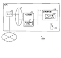
- FIG. 1 is a diagram illustrating an example of a system configuration of an air conditioner connection system according to Embodiment 1.
- FIG. An air conditioner connection system 1000 shown in FIG. 1 is a system that performs power carrier communication using a power line 3 that supplies power to the home as a communication line.
- Power carrier communication is sometimes referred to as PLC (Power Line Communication), PLT (Power Line Telecommunication), power line communication, high-speed power line communication, and power line communication.
- PLC Power Line Communication
- PLT Power Line Telecommunication
- power line communication high-speed power line communication
- power line communication high-speed power line communication
- power line communication typically, power installed in a home or office This is a technique of using wiring as a full-duplex communication line having a bus network configuration.
- the air conditioner connection system 1000 includes a router 10 that connects the Internet 1 and a home LAN (Local Area Network) 2, and a PLC parent that is communicably connected to the Internet 1 via the home LAN 2.
- the air conditioner 100 having the PLC slave unit module 110 connected to the PLC 20 via the power line 3, and the remote control device 200 capable of wireless communication with the air conditioner 100. It is configured with.
- the Internet 1 is an example of an external network.
- the home LAN 2 is an example of a home network.
- the PLC master device 20 is an example of a third device.
- the PLC slave module 110 is an example of a first device.
- the remote operation device 200 is an example of a second device.
- the home LAN 2 connects home devices, which are electronic devices and electrical devices installed in the home, in a state where they can communicate with each other, and connects each home device and the Internet 1 in a state where they can communicate.
- the power line 3 is connected to an external power supply terminal provided in the house, and supplies power supplied from a commercial power source to each home device.
- the power line 3 supplies a carrier wave on which a communication signal is superimposed to each home device.
- the communication signal includes data signals related to telephone calls, mail transmission / reception, and Internet communication.
- the PLC master unit 20 has a built-in LAN router function and is connected to the home LAN 2.
- the PLC master device 20 includes an authentication start button 21 that is manually operated when starting PLC with the air conditioner 100.
- the PLC master device 20 performs authentication for performing PLC communication (hereinafter referred to as “PLC communication” as appropriate) with the PLC slave device module 110 for a certain period of time after receiving the operation of the authentication start button 21.
- PLC communication PLC communication
- the process shifts to an authentication mode in which the process (hereinafter referred to as “PLC authentication process” as appropriate) can be executed.
- the air conditioner 100 is an indoor unit installed in the house.
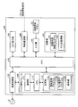
- FIG. 2 is a block diagram illustrating an example of a functional configuration of the air conditioner according to Embodiment 1.
- the air conditioner 100 includes a PLC slave module 110 that performs PLC authentication processing, a power supply circuit unit 120 that connects the power line 3 and the PLC slave module 110, and a plurality of LEDs (Light Emitting).
- LED display unit 130 for turning on (Diode), a wireless communication unit 140 for receiving various data from the remote operation device 200 by wireless communication, an input unit 150 for receiving various inputs, and an authentication for accepting a manual operation for starting a PLC authentication process.
- a start button 151, a storage unit 160 that stores programs and data used for various processes executed in the air conditioner 100, and a CPU (Central Processing Unit) 170 that executes various processes of the air conditioner 100 are provided.
- the PLC slave unit module 110 stores a communication unit 111 that performs communication with the PLC master unit 20, and programs and data used for various processes executed in the PLC slave unit module 110.
- a storage unit 112 and a CPU 113 that executes various processes in the PLC slave module 110 are provided.
- the PLC slave module 110 When the PLC slave module 110 is not performing the PLC communication and the PLC authentication process, for example, the PLC slave module 110 operates in a standby mode prepared for the PLC communication and the PLC authentication process.
- the storage unit 112 stores an authentication processing program 112a, a PLC communication program 112b, and an encryption key 112c.
- the authentication processing program 112a provides a function for executing PLC authentication processing with the PLC master device 20.
- the PLC communication program 112b provides a function for performing PLC communication.
- the encryption key 112c is shared with the PLC master device 20 as a key for encrypting data exchanged by PLC communication when the authentication processing executed using the authentication processing program 112a is successful. .
- the CPU 113 executes the PLC authentication process with the PLC master device 20 by executing the authentication process program 112a.
- the CPU 113 receives an instruction to shift to the authentication mode from the CPU 170, the CPU 113 shifts to the authentication mode for starting the PLC authentication processing from the standby mode, reads the authentication processing program 112a from the storage unit 112, and communicates with the PLC master device 20.
- the authentication process is started.
- the CPU 113 sends the result of the authentication process to the CPU 170.
- the CPU 113 stores the encryption key 112c shared with the PLC master device 20 in the storage unit 120.
- the CPU 113 that executes the authentication processing program 112a is an example of an authentication processing unit.
- the power supply circuit unit 120 connects the PLC slave unit module 110 and the PLC master unit 20 to a state in which PLC communication is possible via the power line 3.
- the power supply circuit unit 120 converts the communication signal superimposed on the carrier wave supplied via the power line 3 into a signal receivable by the PLC slave module 110.
- the LED display unit 130 turns on the LED in a pattern corresponding to the authentication result of the PLC authentication process.
- the wireless communication unit 140 receives a packet including an authentication start request from the remote operation device 200.
- the input unit 150 receives an operation of the authentication start button 151 as an input of an authentication start request.
- the authentication start button 151 is an operation unit for performing a manual authentication start request instead of transmitting an authentication start request from the remote operation device 200, and is normally used when an authentication start request is transmitted by the remote operation device 200. None happen.
- the storage unit 160 stores an authentication processing control program 161 and PLC state information 162.
- the authentication process control program 161 provides a function for controlling the PLC slave module 110 so as to execute the PLC authentication process with the PLC master unit 20.
- the PLC status information 162 includes the result of the authentication process by the PLC slave module 110.
- the authentication result included in the PLC state information 162 is referred to when the CPU 170 determines the lighting pattern of the LED display unit 130.
- the PLC state information 162 includes information related to the PLC master device 20.
- the information of the PLC master device 20 included in the PLC state information 162 is, for example, a PLC that is automatically executed by the CPU 170 when power is turned on to recover from a power failure when a power failure occurs and power supply is cut off. Used for communication resumption processing.
- the CPU 170 controls the PLC slave module 110 so as to execute the PLC authentication process by executing the authentication process control program 161. Specifically, when receiving a packet from the remote control device 200, the CPU 170 determines whether the received packet is a packet related to operation control of the air conditioner 100 or a packet related to PLC authentication processing. When the received packet is related to the authentication start request, the CPU 170 sends an instruction to shift to the authentication mode to the PLC slave module 110. The CPU 170 determines a lighting pattern of the LED display unit 130 based on the result of the authentication process included in the PLC state information 162, and lights the LED display unit 130.
- the CPU 170 that executes the authentication processing control program 161 is an example of an authentication processing control unit.
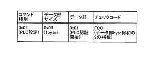
- FIG. 3 is a diagram illustrating a configuration example of a received packet according to the first embodiment.
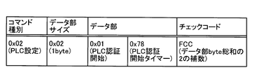
- the received packet includes a command type indicating the content of the command, a data part size indicating the size of data inserted into the data part, a data part into which data is inserted, and data stored in the data part. Consists of a check code for checking consistency.
- the CPU 170 determines whether the packet is related to the operation control of the air conditioner 100 or the packet related to the PLC authentication process based on the value stored in the command type area of the received packet.
- CPU 170 determines the end of data stored in the data portion area based on the value stored in the data portion size area of the received packet.
- CPU 170 obtains a PLC authentication processing start request and a setting value related to the PLC authentication processing from the data portion of the received packet.
- the CPU 170 compares the calculated value from the data stored in the data part of the received packet with the value stored in the check code area, so that the data stored in the data part area is authentic. Determine whether.
- In the check code area a 2's complement of the total value (byte total) of data stored in the data portion is stored.
- CPU 170 discards the received packet when the data stored in the area of the data part is invalid.
- FIG. 3 is an example of a received packet, and is not limited to the example shown in FIG. In order to reduce the packet size of the received packet, data allocation in units of bits may be performed.
- the check code stored in the check code area is not limited to the two's complement of the byte sum of the data part, and it can be determined whether the data stored in the data part area is authentic. Any check code can be adopted.
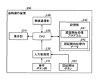
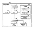
- FIG. 4 is a block diagram illustrating an example of a functional configuration of the remote control device according to the first embodiment.
- the remote operation device 200 includes an input control that controls input from a display unit 210 that displays various types of information, a wireless communication unit 220 that performs wireless communication, an operation button group 231, and an authentication start button 232.
- Unit 230 storage unit 240 that stores programs and data used for various processes in remote operation device 200, and CPU 250 that executes various processes in remote operation device 200.
- Display unit 210 displays information related to operation control of air conditioner 100.
- the wireless communication unit 220 transmits a packet related to operation control of the air conditioner 100 and a packet related to PLC communication.
- the input control unit 230 sends an input signal corresponding to the manual operation of the operation button group 231 and an input signal corresponding to the manual operation of the authentication start button to the CPU 250.
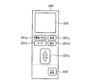
- FIG. 5 is a diagram illustrating an example of an external configuration of the remote control device according to the first embodiment. As shown in FIG. 5, as a control button group 231, a button 231 a for operating and stopping the air conditioner 100 and a switching of the operation mode of the air conditioner 100 are provided on the casing of the remote control device 200.
- a button 231b for performing an operation a button 231c for performing an adjustment operation of wind force from the air conditioner 100, a button 231d for performing an operation of adjusting the wind direction from the air conditioner 100, A button 231e for performing selection during various operations is provided.
- An authentication start button 232 for transmitting a PLC authentication processing start request to the air conditioner 100 is provided on the casing of the remote operation device 200 independently of the operation button group 231.
- the storage unit 240 stores an authentication start processing program 241 and authentication start processing data 242.
- the authentication start processing program 241 receives the operation of the authentication start button 232, the authentication start processing program 241 provides a function for generating a packet for PLC authentication processing including a request for starting the PLC authentication processing and transmitting the packet to the air conditioner 100.
- the authentication start processing data 242 is composed of data necessary for generating a packet for PLC authentication processing.
- the CPU 250 generates a packet including a PLC authentication processing start request by executing the authentication start processing program 241 and transmits the packet to the air conditioner 100. Specifically, when receiving the operation of the authentication start button 232, the CPU 250 generates a packet for PLC authentication processing using the authentication start processing data 242. The CPU 250 transmits the PLC authentication processing packet to the air conditioner 100 via the wireless communication unit 220.
- the CPU 250 that executes the authentication start processing program 241 is an example of an authentication start processing unit.
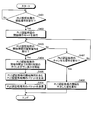
- FIGS. 6 to 8 are flowcharts showing a flow of processing executed in the air conditioner connection system according to Embodiment 1.
- the flow of processing performed by the remote operation device 200 will be described with reference to FIG.
- the processing illustrated in FIG. 6 is realized by the CPU 250 executing the authentication start processing program 241 stored in the storage unit 240.
- the remote operation device 200 determines whether a PLC authentication processing start operation has been received (step S ⁇ b> 101). That is, the remote operation device 200 determines whether an operation of the authentication start button 232 has been accepted.
- the remote operation device 200 repeats the same determination when the result of the determination is that the start operation of the PLC authentication process has not been accepted (No in step S101). On the other hand, if the remote control device 200 receives a PLC authentication processing start operation as a result of the determination (step S101, Yes), it generates a packet for the PLC authentication processing (step S102). Subsequently, the remote control device 200 transmits the packet for PLC authentication processing generated in step S102 to the air conditioner 100 (step S103), and ends the processing shown in FIG.
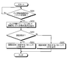
- the flow of processing by the air conditioner 100 will be described with reference to FIG.
- the processing shown in FIG. 7 is realized by the CPU 170 executing the authentication processing control program 161 stored in the storage unit 160.
- the air conditioner 100 determines whether a packet for PLC authentication processing has been received (step S201). That is, the air conditioner 100 refers to the command type of the received packet and determines whether the received packet is a packet related to the PLC authentication process.
- step S201 If the air conditioner 100 has not received the packet for the PLC authentication process as a result of the determination (step S201, No), the determination is repeated. On the other hand, when the air conditioner 100 receives a packet for PLC authentication processing as a result of the determination (step S201, Yes), the air conditioner 100 instructs the PLC slave unit module 110 to enter the authentication mode. It is sent out (step S202).
- the air conditioner 100 determines whether the PLC authentication is successful based on the result of the authentication process sent from the PLC slave module 110 (step S203).
- step S203 if the PLC authentication is successful (step S203, Yes), the air conditioner 100 turns on the LED of the LED display unit 130 in a pattern corresponding to the authentication success (step S204), and is shown in FIG. End the process.
- step S203, No if the air conditioner 100 does not succeed in the PLC authentication (if it fails) (step S203, No) as a result of the determination, the air conditioner 100 uses a pattern corresponding to the authentication failure of the LED display unit 130. The LED is turned on (step S205), and the process shown in FIG.
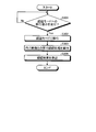
- the flow of processing by the PLC slave module 110 will be described with reference to FIG.
- the processing illustrated in FIG. 8 is realized by the CPU 113 executing the authentication processing program 112a stored in the storage unit 112. As shown in FIG. 7, the PLC slave module 110 determines whether an instruction to shift to the authentication mode has been received (step S301).
- the PLC slave module 110 repeats the determination when the determination result shows that the instruction to shift to the authentication mode has not been received (No in step S301). On the contrary, when the PLC slave unit 110 receives an instruction to shift to the authentication mode as a result of the determination (step S301, Yes), the PLC slave unit module 110 enters the authentication mode for starting the PLC authentication process from the standby mode. Transition is made (step S302).
- the PLC slave unit module 110 executes a PLC authentication process with the PLC master unit 20 (step S303).
- the PLC slave module 110 sends the authentication result of the PLC authentication process to the CPU 170 (step S304), and the process shown in FIG. 8 is finished.
- the user in the air conditioner connection system 1000, the user can start the PLC authentication process by operating the remote control device 200 without directly touching the PLC slave module 110. For this reason, for example, PLC authentication processing when connecting by power carrier communication can be easily executed for an installation-type device installed at a high place in the house such as the air conditioner 100. Further, according to the first embodiment, PLC authentication processing from a remote location can be started as long as wireless communication by remote operation device 200 is possible. For this reason, there is also an effect that the user can perform initial work at the time of installation without going back and forth between the air conditioner 100 and the PLC master device 20.
- Embodiment 2 FIG. In the following second embodiment, an example in which the start time of the PLC authentication process is set in the remote operation device 200 will be described.
- FIG. 9 is a block diagram showing a functional configuration of the remote control device according to the second embodiment.
- the remote control device 200 according to the second embodiment is different from the first embodiment in the points described below. That is, the storage unit 240 stores the authentication start time setting program 243.
- the authentication start time setting program 243 provides a function for accepting the setting of the start time of the PLC authentication process from the user.
- the authentication start time setting program 243 is a function for counting down the remaining time for reaching the start time of the PLC authentication process and displaying it on the display unit 210 when the start time of the PLC authentication process is determined by the user I will provide a.
- the authentication start processing program 241 is for the PLC authentication process including the start time of the PLC authentication process when the user has determined the start time of the PLC authentication process by the function provided by the authentication start time setting program 243. For transmitting the packet to the air conditioner 100 is provided.
- the CPU 250 executes a process related to the setting of the start time of the PLC authentication process by executing the authentication start time setting program 243. Specifically, when the CPU 250 accepts the operation of the authentication start button 232, the CPU 250 executes a start operation mode of the PLC authentication process that allows the user to set the start time of the PLC authentication process. Subsequently, when accepting an operation for determining the start time of the PLC authentication process, the CPU 250 counts down the remaining time for reaching the start time of the PLC authentication process and displays it on the display unit 210.
- the CPU 250 executes the authentication start processing program 241 and receives a confirmation operation of the start time of the PLC authentication process
- the CPU 250 transmits a packet for the PLC authentication process including the start time of the PLC authentication process to the air conditioner 100.
- the CPU 250 that executes the authentication start time setting program 243 is an example of a time setting unit.
- the authentication process control program 161 stored in the storage unit 160 of the air conditioner 100 receives the packet for the PLC authentication process, if the start time of the PLC authentication process is set, the set start time is set. A function for sending an instruction to shift to the authentication mode to the PLC slave module 110 after waiting for arrival is provided.
- the CPU 170 waits for the set start time to reach the PLC slave unit An instruction to shift to the authentication mode is sent to the module 110.
- FIG. 10 is a diagram illustrating a configuration example of a received packet according to the second embodiment.
- the received packet according to Embodiment 2 in addition to the configuration shown in FIG. 3, an area for storing the start time of the PLC authentication process is provided in the data part.
- the CPU 170 refers to the start time stored in the data section, and waits for the PLC slave module 110 to send an instruction to shift to the authentication mode until the set start time is reached.
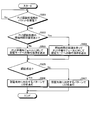
- FIG. 11 and FIG.13 is a flowchart which shows the flow of the process performed in the air conditioner connection system which concerns on Embodiment 2.
- FIG. FIG. 12 is a diagram illustrating an operation example of the remote control device according to the second embodiment.
- the flow of processing performed by the remote operation device 200 will be described with reference to FIGS.
- the processing illustrated in FIG. 11 is realized by the CPU 250 executing the authentication start processing program 241 and the authentication start time setting program 243 stored in the storage unit 240.
- the remote operation device 200 determines whether a PLC authentication processing start operation has been received (step S ⁇ b> 401). That is, the remote control device 200 determines whether an operation of the authentication start button 232 has been accepted (see step S1 shown in FIG. 12).
- the remote operation device 200 repeats the same determination when the result of the determination is that the start operation of the PLC authentication process has not been accepted (No at step S401). On the contrary, when the remote control device 200 receives a start operation of the PLC authentication process as a result of the determination (Yes in step S401), the remote operation device 200 enables the user to set the start time of the PLC authentication process.
- the start operation mode is executed (step S402).
- the remote operation device 200 determines whether an operation for confirming the start time of the PLC authentication process has been accepted (step S403). That is, the remote operation device 200 determines whether or not the confirmation operation of the button 233 has been accepted after the start time setting operation by the button 231e (see step S2 to step S3 shown in FIG. 12).
- the remote operation device 200 When the remote operation device 200 accepts an operation to confirm the start time of the PLC authentication process as a result of the determination (step S403, Yes), the remote operation device 200 starts a countdown display of the remaining time until the start time of the PLC authentication process is reached. (Step S404). For example, when the start time of the PLC authentication process is 2 minutes, the remote operation device 200 counts down the remaining time from immediately after the operation of the button 233 until the start of the PLC authentication process, and causes the display unit 210 to display it. (See step S4 shown in FIG. 12).
- the remote operation device 200 generates a packet for PLC authentication processing including the start time of the PLC authentication processing (step S405).
- the remote operation device 200 transmits the packet for the PLC authentication process generated in step S405 to the air conditioner 100 (step S406), and ends the process shown in FIG.
- step S403 if the result of determination is that the determination operation for determining the start time of the PLC authentication process has not been accepted (No in step S403), the remote operation device 200 determines whether or not a cancel operation for the PLC authentication process has been accepted. (Step S407). That is, the remote operation device 200 determines whether an operation of the button 234 has been accepted (see FIG. 12).
- the remote operation device 200 returns to the processing procedure of step S403 when it is determined that the PLC authentication processing cancel operation has not been accepted (step S407, No). On the other hand, if the result of determination is that the cancel operation of the PLC authentication process has been accepted (Yes in step S407), the remote control device 200 notifies that the start of the PLC authentication process has been stopped (step S408). ), The process shown in FIG. For example, if the remote operation device 200 accepts the operation of the button 234 before accepting the operation of the button 233, the remote operation device 200 displays a message indicating that the PLC authentication processing has been stopped on the display unit 210.
- the flow of processing by the air conditioner 100 will be described with reference to FIG.
- the process illustrated in FIG. 13 is realized by the CPU 170 executing the authentication process control program 161 stored in the storage unit 160.
- the air conditioner 100 determines whether a packet for PLC authentication processing has been received (step S501). That is, the air conditioner 100 refers to the command type of the received packet and determines whether the received packet is a packet related to the PLC authentication process.
- step S501 If the air conditioner 100 has not received a packet for PLC authentication processing as a result of the determination (step S501, No), the air conditioner 100 repeats the determination. On the other hand, if the air conditioner 100 receives the packet for the PLC authentication process as a result of the determination (step S501, Yes), the air conditioner 100 determines whether the start time of the PLC authentication process is set ( Step S502). That is, the air conditioner 100 refers to the data part of the received packet and determines whether the setting of the start time of the PLC authentication process is included.
- step S503 the air conditioner 100 sends an instruction to shift to the authentication mode to the PLC slave module 110 (step S503).
- step S504 the air conditioner 100 waits for the set start time to reach the PLC slave unit. An instruction to shift to the authentication mode is sent to the module 110 (step S504).
- the air conditioner 100 determines whether the PLC authentication is successful based on the result of the authentication process sent from the PLC slave module 110 (step S505).
- the air conditioner 100 turns on the LED of the LED display unit 130 in a pattern corresponding to the authentication success (step S506) when the PLC authentication is successful (step S505, Yes), and is shown in FIG. End the process.
- the air conditioner 100 uses the pattern corresponding to the authentication failure of the LED display unit 130.
- the LED is turned on (step S507), and the process shown in FIG. 13 ends.
- the user sets the start time of the PLC authentication process by using the remote control device 200, so that the PLC slave unit module 110 and the PLC base unit 20 are connected after the set start time has elapsed.
- the PLC authentication process is executed between. For this reason, for example, even when the PLC master unit 20 and the PLC slave unit 110 need to be in a state where the PLC authentication process can be performed simultaneously or within a few seconds, a time margin can be provided, and the PLC authentication can be performed. Processing can be performed easily.
- by counting down and displaying the remaining time until the PLC authentication process is started on the remote control device 200 it is possible to easily measure the timing for switching the PLC master device 20 to a mode in which the PLC authentication process can be executed. Can do.
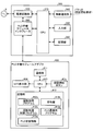
- FIG. 14 is a block diagram illustrating an example of functional configurations of the air conditioner and the PLC slave module adapter according to the third embodiment.
- the air conditioner 300 according to Embodiment 3 receives various data from the remote control device 200 through the power supply circuit unit 320 that connects the power line 3 and the PLC slave unit module interface 380 and wireless communication.
- the wireless communication unit 340, the input unit 350 that receives various inputs, the storage unit 360 that stores programs and data used in various processes executed in the air conditioner 300, and the various processes of the air conditioner 300 A CPU 370, a power supply circuit unit 320, and a PLC slave module interface 380 connected to the CPU 170 are provided.
- the PLC slave unit module interface 380 provides a connector for connection with the PLC slave unit module adapter.
- the connection connector includes a power line for PLC communication, a transmission / reception line for controlling the PLC slave module interface 380, a power supply line to the PLC slave module adapter 400, and ground (GND).
- the CPU 370 transmits the control data for controlling the PLC slave module interface 380 via the PLC slave module interface 380 and the transmission data to be transmitted to the PLC master 20 to the PLC slave module adapter. 400.
- the configurations of the control data and the transmission data are not limited to a specific configuration, and may be configured as one communication packet including the control data and the transmission data data, or may be configured as individual packets. It may be configured as.
- the PLC slave module adapter 400 includes all the functions provided in the PLC slave module 110 described in the first embodiment and a part of the functions provided in the air conditioner 100 described in the first embodiment.
- the PLC slave module adapter 400 includes a communication unit 411 that communicates with the PLC master unit 20, and a storage unit 412 that stores programs and data used for various processes executed in the PLC slave module 110.
- a CPU 413 that executes various processes in the PLC slave module 110, an LED display unit 414 that lights a plurality of LEDs, and an authentication start button 415 that accepts a manual operation for starting a PLC authentication process.
- the storage unit 412 stores the authentication processing program 412a corresponding to the authentication processing program 112a, the encryption key 412b corresponding to the encryption key 112c, the authentication processing control program 412c corresponding to the authentication processing control program 161, and the PLC communication program 112b.
- a corresponding PLC communication program 412d and PLC state information 412e corresponding to the PLC state information 162 are stored.
- the authentication processing control program 412c When the authentication processing control program 412c receives a packet for PLC authentication processing from the air conditioner 300 via the PLC slave module interface 380, is the PLC authentication processing start time set in the packet for PLC authentication processing? When the start time is set, a function for shifting to the authentication mode after waiting for the set start time to be provided is provided. Based on the control data received from the air conditioner 300, the PLC communication program 412d superimposes the transmission data received from the air conditioner 300 on the power supply line, and from the PLC slave unit module interface 380 to the power supply circuit unit 320 and A function for transmitting data to the PLC master device 20 by PLC communication via the power line 3 is provided.
- the CPU 413 determines whether the PLC authentication process packet has a start time for the PLC authentication process, and sets the start time. If there is, it waits for the set start time to reach and shifts to the authentication mode.
- FIG. 15 is a flowchart showing a flow of processing in the air conditioner connection system according to Embodiment 3.
- the processing by the PLC slave module adapter 400 shown in FIG. 15 is realized by the CPU 413 executing the authentication processing program 412a and the authentication processing control program 412c.
- the PLC slave module adapter 400 determines whether or not a packet for PLC authentication processing has been received (step S601).
- step S601 When the PLC slave module adapter 400 has not received the packet for the PLC authentication process as a result of the determination (step S601, No), the determination is repeated. On the contrary, when the PLC slave module adapter 400 receives the packet for the PLC authentication process as a result of the determination (step S601, Yes), it determines whether the start time of the PLC authentication process is set. (Step S602).
- step S603 If it is determined that the PLC authentication processing start time is not set (step S602, No), the PLC slave module adapter 400 proceeds to the authentication mode as it is (step S603). On the other hand, if the result of determination is that there is a setting for the start time of the PLC authentication process (Yes in step S602), the PLC slave module adapter 400 waits for the set start time to arrive and authenticates. The mode is changed (step S604).
- the PLC slave module adapter 400 executes PLC authentication processing with the PLC master 20 (step S605).
- the PLC slave module adapter 400 sends the authentication result of the PLC authentication process to the air conditioner 300 (step S606).
- the PLC slave module adapter 400 turns on the LED of the LED display unit 414 with a pattern corresponding to the authentication result of the PLC authentication process (step S607), and ends the process shown in FIG.
- the PLC authentication process can be realized by using the PLC slave module adapter 400 having the PLC slave module 110 as an external configuration. For this reason, when constructing a system for performing PLC communication in the air conditioner connection system 1000, it can be constructed simply by connecting the PLC slave module adapter 400 to the target in-home equipment. Compared with the case where it is built in, the manufacturing cost of the in-home equipment can be reduced. In addition, since it is not necessary to mount components required for PLC communication in the home device, it is possible to suppress an increase in the size of the home device due to the addition of functions required for PLC communication. In addition, the amount of energy consumption can be reduced by downsizing the home appliances.
- the air conditioner installed at a high place in the house has been described as an example of the house equipment that is difficult to operate manually during the PLC authentication process, but the equipment other than the air conditioner installed in the house Also, the PLC authentication process can be executed by applying the PLC slave module 110 or the PLC slave module adapter 400 described in the above embodiment in the same manner.
- the functions implemented in the PLC slave module 110 and the PLC slave module adapter 400 described in the above embodiment are not limited to the case where the CPU reads and executes a program corresponding to each function. It may be executed by a multi-function circuit such as a system LSI (Large Scale Integration). Each of the above functions may be executed by linking a plurality of processing circuits corresponding to each function.
- LSI Large Scale Integration
- the configuration described in the above embodiment shows an example of the contents of the present invention, and can be combined with another known technique, and can be combined with other configurations without departing from the gist of the present invention. It is also possible to omit or change the part.
Abstract
Description
図1は、実施の形態1における空気調和機接続システムのシステム構成の例を示す図である。図1に示す空気調和機接続システム1000は、宅内に電力を供給する電力線3を通信回線として利用する電力搬送通信を行うシステムである。電力搬送通信は、PLC(Power Line Communication)、PLT(Power Line Telecommunication)、電力線通信、高速電力線通信、電灯線通信と呼ばれることがあり、典型的には、家庭内又はオフィス内に設置される電力配線を、バス型ネットワークの構成を有する全二重通信の通信回線として利用する技術である。なお、電力搬送通信では、高速フーリエ変換、ウェーブレット変換を利用した直交化周波数多重(OFDM:Orthogonal Frequency Domain Multiplex)、ノイズの影響による速度低下を軽減可能な周波数拡散(SS:Spread Spectrum)、及び離散的多周波数(DMT方式)といった各種変調方式を採用することができる。 Embodiment 1 FIG.
1 is a diagram illustrating an example of a system configuration of an air conditioner connection system according to Embodiment 1. FIG. An air
以下の実施の形態2では、遠隔操作装置200において、PLC認証処理の開始時間を設定する例について説明する。 Embodiment 2. FIG.
In the following second embodiment, an example in which the start time of the PLC authentication process is set in the
以下の実施の形態3では、空気調和機100のPLC子機モジュール110を外付け構成とした場合について説明する。図14は、実施の形態3に係る空気調和機及びPLC子機モジュールアダプタの機能構成の例を示すブロック図である。図14に示すように、実施の形態3に係る空気調和機300は、電力線3とPLC子機モジュールインタフェース380とを接続する電源回路部320と、無線通信により遠隔操作装置200から各種データを受信する無線通信部340と、各種入力を受け付ける入力部350と、空気調和機300において実行される各種処理に用いられるプログラム及びデータを記憶する記憶部360と、空気調和機300の各種処理を実行するCPU370と、電源回路部320及びCPU170に接続されるPLC子機モジュールインタフェース380とを備える。
In the following third embodiment, a case where the PLC
Claims (4)
- 電力線を介して通信可能な状態に接続される第1の装置を有する空気調和機と、当該空気調和機と無線通信が可能な第2の装置とを備える空気調和機接続システムであって、
前記空気調和機は、
前記第2の装置から電力搬送通信を実行するための認証処理の開始要求を受信した場合に、前記認証処理を実行するように前記第2の装置を制御する認証処理制御部を備え、
前記第1の装置は、
前記空気調和機の制御下で前記認証処理を実行する認証処理部を備え、
前記第2の装置は、
前記空気調和機に対して前記開始要求を送信する認証開始処理部を備えることを特徴とする空気調和機接続システム。 An air conditioner connection system comprising an air conditioner having a first device connected in a communicable state via a power line, and a second device capable of wireless communication with the air conditioner,
The air conditioner
An authentication process control unit configured to control the second apparatus so as to execute the authentication process when receiving an authentication process start request for executing power carrier communication from the second apparatus;
The first device includes:
An authentication processing unit that executes the authentication process under the control of the air conditioner;
The second device includes:
An air conditioner connection system comprising: an authentication start processing unit that transmits the start request to the air conditioner. - 前記第2の装置は、
前記認証処理の開始時間の設定を受け付けるとともに、前記開始時間が確定された場合には前記開始時間に到達するまでの残り時間をカウントダウンさせて表示部に表示させる時間設定部をさらに備え、
前記認証開始処理部は、前記時間設定部において前記開始時間が確定された場合には、前記開始時間及び前記開始要求を前記空気調和機に送信し、
前記認証処理制御部は、前記開始時間及び前記開始要求を前記第2の装置から受信すると、前記開始時間の到達を待って前記認証処理を実行するように前記第1の装置を制御することを特徴とする請求項1に記載の空気調和機接続システム。 The second device includes:
In addition to accepting the setting of the start time of the authentication process, if the start time is fixed, further comprising a time setting unit for counting down the remaining time until the start time is reached and displaying on the display unit,
When the start time is determined by the time setting unit, the authentication start processing unit transmits the start time and the start request to the air conditioner,
When the authentication processing control unit receives the start time and the start request from the second device, the authentication processing control unit controls the first device to execute the authentication processing after waiting for the start time to arrive. The air conditioner connection system according to claim 1, wherein the system is an air conditioner connection system. - 前記空気調和機に外付されるモジュールとして前記第1の装置を構成することを特徴とする請求項1又は2に記載の空気調和機接続システム。 The air conditioner connection system according to claim 1 or 2, wherein the first device is configured as a module externally attached to the air conditioner.
- 電力線を介して通信可能な状態に接続される第1の装置を有する空気調和機と、当該空気調和機と無線通信が可能な第2の装置と、宅内ネットワークを介して外部ネットワークと通信可能な状態に接続されるとともに前記電力線を介して前記第1の装置と通信可能に接続される第3の装置とを備える空気調和機接続システムであって、
前記空気調和機は、
前記第2の装置から電力搬送通信を実行するための認証処理の開始要求を受信した場合に、前記第3の装置との間で前記認証処理を実行するように前記第1の装置を制御する認証処理制御部を備え、
前記第1の装置は、
前記空気調和機の制御下で前記認証処理を実行する認証処理部を備え、
前記第2の装置は、
前記空気調和機に対して前記開始要求を送信する認証開始処理部を備えることを特徴とする空気調和機接続システム。 An air conditioner having a first device connected in a communicable state via a power line, a second device capable of wireless communication with the air conditioner, and communicable with an external network via a home network An air conditioner connection system comprising: a third device connected to a state and communicatively connected to the first device via the power line,
The air conditioner
When receiving a request for starting authentication processing for executing power carrier communication from the second device, the first device is controlled to execute the authentication processing with the third device. It has an authentication processing control unit,
The first device includes:
An authentication processing unit that executes the authentication process under the control of the air conditioner;
The second device includes:
An air conditioner connection system comprising: an authentication start processing unit that transmits the start request to the air conditioner.
Priority Applications (5)
| Application Number | Priority Date | Filing Date | Title |
|---|---|---|---|
| PCT/JP2015/057350 WO2016143130A1 (en) | 2015-03-12 | 2015-03-12 | Air conditioner connection system |
| EP15871316.4A EP3141833B1 (en) | 2015-03-12 | 2015-03-12 | Air conditioner connection system |
| CN201580076241.7A CN107250681B (en) | 2015-03-12 | 2015-03-12 | Air conditioner connects system |
| JP2017504532A JP6320622B2 (en) | 2015-03-12 | 2015-03-12 | Air conditioner connection system |
| US15/538,724 US10628564B2 (en) | 2015-03-12 | 2015-03-12 | Air conditioner connection system |
Applications Claiming Priority (1)
| Application Number | Priority Date | Filing Date | Title |
|---|---|---|---|
| PCT/JP2015/057350 WO2016143130A1 (en) | 2015-03-12 | 2015-03-12 | Air conditioner connection system |
Publications (1)
| Publication Number | Publication Date |
|---|---|
| WO2016143130A1 true WO2016143130A1 (en) | 2016-09-15 |
Family
ID=56878559
Family Applications (1)
| Application Number | Title | Priority Date | Filing Date |
|---|---|---|---|
| PCT/JP2015/057350 WO2016143130A1 (en) | 2015-03-12 | 2015-03-12 | Air conditioner connection system |
Country Status (5)
| Country | Link |
|---|---|
| US (1) | US10628564B2 (en) |
| EP (1) | EP3141833B1 (en) |
| JP (1) | JP6320622B2 (en) |
| CN (1) | CN107250681B (en) |
| WO (1) | WO2016143130A1 (en) |
Cited By (2)
| Publication number | Priority date | Publication date | Assignee | Title |
|---|---|---|---|---|
| CN108344112A (en) * | 2018-03-08 | 2018-07-31 | 上海物麒科技有限公司 | It is matched by pipeline and encodes the multi-online air-conditioning system PLC network-building methods matched |
| CN108648432A (en) * | 2018-06-04 | 2018-10-12 | 广东万家乐燃气具有限公司 | The more control terminal networking communication control systems of electric appliance and water heater control method |
Families Citing this family (7)
| Publication number | Priority date | Publication date | Assignee | Title |
|---|---|---|---|---|
| US10356812B2 (en) * | 2017-02-06 | 2019-07-16 | Qualcomm Incorporated | Variable-length transmission schemes |
| US11489552B2 (en) * | 2018-03-01 | 2022-11-01 | Daikin Industries, Ltd. | Air conditioning system |
| CN108626847B (en) * | 2018-04-13 | 2019-12-31 | 珠海格力电器股份有限公司 | Multi-connected air conditioning unit system |
| CN108592302B (en) * | 2018-04-13 | 2021-04-30 | 珠海格力电器股份有限公司 | Data transmission method, apparatus, multi-split system, and storage medium |
| US10648686B2 (en) | 2018-05-15 | 2020-05-12 | Johnson Controls Technology Company | HVAC high voltage powerline communication systems and methods |
| RU192788U1 (en) * | 2019-05-08 | 2019-10-01 | Общество с ограниченной ответственностью "ФОРС Продакшн" | Multilayer metal pipe |
| CN115540231A (en) * | 2021-06-29 | 2022-12-30 | 佛山市顺德区美的电子科技有限公司 | Air conditioner safety protection method and device, storage medium and terminal equipment |
Citations (6)
| Publication number | Priority date | Publication date | Assignee | Title |
|---|---|---|---|---|
| JP2004215232A (en) | 2002-12-19 | 2004-07-29 | Buffalo Inc | Encryption key setting system, access point, and encryption key setting method, and authentication code setting system |
| JP2005274117A (en) * | 2004-03-22 | 2005-10-06 | Lg Electronics Inc | Central control system for multiple air conditioner and method of operating the same |
| JP2007116378A (en) * | 2005-10-19 | 2007-05-10 | Matsushita Electric Works Ltd | Power line communication security system |
| JP2009044407A (en) * | 2007-08-08 | 2009-02-26 | Sumitomo Electric Ind Ltd | Plc system and setting method of its common key |
| JP2012161001A (en) * | 2011-02-02 | 2012-08-23 | Toshiba Carrier Corp | Control system, face authentication system used with the control system, and portable terminal |
| US20140012422A1 (en) * | 2004-08-11 | 2014-01-09 | Emerson Climate Technologies, Inc. | Method and Apparatus for Monitoring Refrigerant-Cycle Systems |
Family Cites Families (24)
| Publication number | Priority date | Publication date | Assignee | Title |
|---|---|---|---|---|
| JP2002245235A (en) * | 2001-02-20 | 2002-08-30 | Hitachi Ltd | Home electrical appliance, applicant registering method, order-accepting method, data processing system |
| JP2003339085A (en) * | 2002-05-21 | 2003-11-28 | Mitsubishi Electric Corp | House code setting telephone set |
| KR100555381B1 (en) | 2002-12-19 | 2006-02-24 | 멜코 인코포레이티드 | Encryption key setup system, access point, encryption key setup method, and authentication code setup system |
| JP4129594B2 (en) | 2003-04-15 | 2008-08-06 | 株式会社日立製作所 | Air conditioning system |
| JP3870280B2 (en) | 2004-01-15 | 2007-01-17 | 株式会社日立製作所 | Air conditioner and power line communication system |
| US7424343B2 (en) * | 2004-08-11 | 2008-09-09 | Lawrence Kates | Method and apparatus for load reduction in an electric power system |
| US6990335B1 (en) * | 2004-11-18 | 2006-01-24 | Charles G. Shamoon | Ubiquitous connectivity and control system for remote locations |
| CN101180807A (en) * | 2005-04-26 | 2008-05-14 | 赛米泰克创新有限公司 | Communications method and apparatus |
| JP2007164612A (en) | 2005-12-15 | 2007-06-28 | Matsushita Electric Works Ltd | Remote control system |
| WO2008148053A1 (en) * | 2007-05-24 | 2008-12-04 | Federal Law Enforcement Development Services, Inc. | Led light global positioning and routing communication system |
| KR20090041606A (en) * | 2007-10-24 | 2009-04-29 | 엘지전자 주식회사 | Air conditioning system |
| US8345778B2 (en) * | 2007-10-29 | 2013-01-01 | Lightwaves Systems, Inc. | High bandwidth data transport system |
| JP2010267240A (en) * | 2009-04-16 | 2010-11-25 | Toshiba Corp | Recording device |
| CN102301353A (en) * | 2009-11-30 | 2011-12-28 | 松下电器产业株式会社 | Portable communication apparatus, communication method, integrated circuit, and program |
| CN103098108B (en) * | 2010-11-25 | 2017-09-08 | 松下电器(美国)知识产权公司 | Communication equipment |
| US20120232969A1 (en) * | 2010-12-31 | 2012-09-13 | Nest Labs, Inc. | Systems and methods for updating climate control algorithms |
| JP5579090B2 (en) * | 2011-01-25 | 2014-08-27 | 三菱電機株式会社 | Home appliance system and wireless setting method |
| CA3044757C (en) * | 2011-10-21 | 2021-11-09 | Google Llc | User-friendly, network connected learning thermostat and related systems and methods |
| US9191203B2 (en) * | 2013-08-06 | 2015-11-17 | Bedrock Automation Platforms Inc. | Secure industrial control system |
| CN102945029B (en) * | 2012-10-31 | 2014-12-10 | 鸿富锦精密工业(深圳)有限公司 | Intelligent gateway, smart home system and intelligent control method for home appliance equipment |
| US9621433B2 (en) * | 2012-12-28 | 2017-04-11 | Panasonic Intellectual Property Corporation Of America | Control method used in a remote control system |
| JP2015121392A (en) * | 2013-12-25 | 2015-07-02 | ダイキン工業株式会社 | Air conditioning system |
| US10506015B2 (en) * | 2015-05-04 | 2019-12-10 | Johnson Controls Technology Company | HVAC equipment providing a dynamic web interface systems and methods |
| EP3096304B1 (en) * | 2015-05-18 | 2020-05-06 | Helvar Oy Ab | Method and arrangement for controlling appliances from a distance |
-
2015
- 2015-03-12 US US15/538,724 patent/US10628564B2/en active Active
- 2015-03-12 CN CN201580076241.7A patent/CN107250681B/en active Active
- 2015-03-12 EP EP15871316.4A patent/EP3141833B1/en active Active
- 2015-03-12 WO PCT/JP2015/057350 patent/WO2016143130A1/en active Application Filing
- 2015-03-12 JP JP2017504532A patent/JP6320622B2/en active Active
Patent Citations (6)
| Publication number | Priority date | Publication date | Assignee | Title |
|---|---|---|---|---|
| JP2004215232A (en) | 2002-12-19 | 2004-07-29 | Buffalo Inc | Encryption key setting system, access point, and encryption key setting method, and authentication code setting system |
| JP2005274117A (en) * | 2004-03-22 | 2005-10-06 | Lg Electronics Inc | Central control system for multiple air conditioner and method of operating the same |
| US20140012422A1 (en) * | 2004-08-11 | 2014-01-09 | Emerson Climate Technologies, Inc. | Method and Apparatus for Monitoring Refrigerant-Cycle Systems |
| JP2007116378A (en) * | 2005-10-19 | 2007-05-10 | Matsushita Electric Works Ltd | Power line communication security system |
| JP2009044407A (en) * | 2007-08-08 | 2009-02-26 | Sumitomo Electric Ind Ltd | Plc system and setting method of its common key |
| JP2012161001A (en) * | 2011-02-02 | 2012-08-23 | Toshiba Carrier Corp | Control system, face authentication system used with the control system, and portable terminal |
Non-Patent Citations (1)
| Title |
|---|
| See also references of EP3141833A4 |
Cited By (2)
| Publication number | Priority date | Publication date | Assignee | Title |
|---|---|---|---|---|
| CN108344112A (en) * | 2018-03-08 | 2018-07-31 | 上海物麒科技有限公司 | It is matched by pipeline and encodes the multi-online air-conditioning system PLC network-building methods matched |
| CN108648432A (en) * | 2018-06-04 | 2018-10-12 | 广东万家乐燃气具有限公司 | The more control terminal networking communication control systems of electric appliance and water heater control method |
Also Published As
| Publication number | Publication date |
|---|---|
| EP3141833A1 (en) | 2017-03-15 |
| CN107250681B (en) | 2019-09-24 |
| EP3141833B1 (en) | 2020-11-18 |
| US10628564B2 (en) | 2020-04-21 |
| US20180004920A1 (en) | 2018-01-04 |
| CN107250681A (en) | 2017-10-13 |
| EP3141833A4 (en) | 2017-07-05 |
| JP6320622B2 (en) | 2018-05-09 |
| JPWO2016143130A1 (en) | 2017-07-27 |
Similar Documents
| Publication | Publication Date | Title |
|---|---|---|
| JP6320622B2 (en) | Air conditioner connection system | |
| US7956492B2 (en) | Outlet switch socket device | |
| WO2013163674A1 (en) | Modular wireless power, light and automation control | |
| WO2011087082A1 (en) | Illumination apparatus | |
| CN105409237A (en) | Wireless light pairing, dimming and control | |
| JP2009194826A (en) | Power line communication apparatus, power line communication system, and registration processing method | |
| KR100770856B1 (en) | Device and method for performing multi- functions using unique port in wireless terminal | |
| WO2011125845A1 (en) | Illumination apparatus | |
| CN106354060B (en) | Master-slave communication method of guest room control device | |
| US20070086514A1 (en) | Integrated power supply and communication device | |
| JP2008293367A (en) | Serial communication device | |
| JP2007245891A (en) | In-vehicle controller | |
| KR20110054199A (en) | Power supply management poe hub | |
| US7492109B2 (en) | Apparatus for controlling lamp source and electric equipment and power socket therof | |
| US8351517B2 (en) | Electronic device | |
| JP6100713B2 (en) | Communication apparatus and communication system | |
| KR20100026440A (en) | Device for controlling the equipment by using sms and drving method thereof | |
| CN106502223B (en) | Hotel guest room monitoring management system | |
| JP2004355171A (en) | Home network system and its control method | |
| TWI715029B (en) | Communication device and communication system for lighting control | |
| CN105531906A (en) | Wireless communication device and method for controlling wireless communication device | |
| KR100822346B1 (en) | Virtual lan module board, switch system including the same, and method of initial setting the same | |
| KR100817571B1 (en) | Apparatus and method for management of a repeater in the security system | |
| US20190204795A1 (en) | Communication System for Power Outlet Control Devices | |
| JP2017139596A (en) | Wireless communication device, wireless communication system and wireless network setting method |
Legal Events
| Date | Code | Title | Description |
|---|---|---|---|
| REEP | Request for entry into the european phase |
Ref document number: 2015871316 Country of ref document: EP |
|
| WWE | Wipo information: entry into national phase |
Ref document number: 2015871316 Country of ref document: EP |
|
| 121 | Ep: the epo has been informed by wipo that ep was designated in this application |
Ref document number: 15871316 Country of ref document: EP Kind code of ref document: A1 |
|
| ENP | Entry into the national phase |
Ref document number: 2017504532 Country of ref document: JP Kind code of ref document: A |
|
| WWE | Wipo information: entry into national phase |
Ref document number: 15538724 Country of ref document: US |
|
| NENP | Non-entry into the national phase |
Ref country code: DE |