WO2016132891A1 - Approaching-body warning device for automobile - Google Patents
Approaching-body warning device for automobile Download PDFInfo
- Publication number
- WO2016132891A1 WO2016132891A1 PCT/JP2016/053076 JP2016053076W WO2016132891A1 WO 2016132891 A1 WO2016132891 A1 WO 2016132891A1 JP 2016053076 W JP2016053076 W JP 2016053076W WO 2016132891 A1 WO2016132891 A1 WO 2016132891A1
- Authority
- WO
- WIPO (PCT)
- Prior art keywords
- vehicle
- detection
- sound
- alarm
- control device
- Prior art date
Links
- 238000001514 detection method Methods 0.000 claims abstract description 129
- 238000013459 approach Methods 0.000 claims abstract description 60
- 238000000926 separation method Methods 0.000 claims description 26
- 238000012545 processing Methods 0.000 claims description 17
- 238000004364 calculation method Methods 0.000 claims description 9
- 241001465754 Metazoa Species 0.000 claims description 3
- 238000004891 communication Methods 0.000 description 44
- 238000000034 method Methods 0.000 description 8
- 238000010586 diagram Methods 0.000 description 7
- 230000006870 function Effects 0.000 description 4
- 238000009434 installation Methods 0.000 description 4
- 230000005540 biological transmission Effects 0.000 description 2
- 238000003384 imaging method Methods 0.000 description 2
- 230000001133 acceleration Effects 0.000 description 1
- 230000036626 alertness Effects 0.000 description 1
- 230000006399 behavior Effects 0.000 description 1
- 239000003086 colorant Substances 0.000 description 1
- 230000003111 delayed effect Effects 0.000 description 1
- 230000000694 effects Effects 0.000 description 1
- 230000009191 jumping Effects 0.000 description 1
- 238000012986 modification Methods 0.000 description 1
- 230000004048 modification Effects 0.000 description 1
- 238000003909 pattern recognition Methods 0.000 description 1
- 238000010248 power generation Methods 0.000 description 1
Images


Classifications
-
- G—PHYSICS
- G08—SIGNALLING
- G08G—TRAFFIC CONTROL SYSTEMS
- G08G1/00—Traffic control systems for road vehicles
- G08G1/16—Anti-collision systems
- G08G1/166—Anti-collision systems for active traffic, e.g. moving vehicles, pedestrians, bikes
-
- B—PERFORMING OPERATIONS; TRANSPORTING
- B60—VEHICLES IN GENERAL
- B60Q—ARRANGEMENT OF SIGNALLING OR LIGHTING DEVICES, THE MOUNTING OR SUPPORTING THEREOF OR CIRCUITS THEREFOR, FOR VEHICLES IN GENERAL
- B60Q5/00—Arrangement or adaptation of acoustic signal devices
- B60Q5/005—Arrangement or adaptation of acoustic signal devices automatically actuated
-
- B—PERFORMING OPERATIONS; TRANSPORTING
- B60—VEHICLES IN GENERAL
- B60Q—ARRANGEMENT OF SIGNALLING OR LIGHTING DEVICES, THE MOUNTING OR SUPPORTING THEREOF OR CIRCUITS THEREFOR, FOR VEHICLES IN GENERAL
- B60Q9/00—Arrangement or adaptation of signal devices not provided for in one of main groups B60Q1/00 - B60Q7/00, e.g. haptic signalling
- B60Q9/008—Arrangement or adaptation of signal devices not provided for in one of main groups B60Q1/00 - B60Q7/00, e.g. haptic signalling for anti-collision purposes
-
- B—PERFORMING OPERATIONS; TRANSPORTING
- B60—VEHICLES IN GENERAL
- B60R—VEHICLES, VEHICLE FITTINGS, OR VEHICLE PARTS, NOT OTHERWISE PROVIDED FOR
- B60R1/00—Optical viewing arrangements; Real-time viewing arrangements for drivers or passengers using optical image capturing systems, e.g. cameras or video systems specially adapted for use in or on vehicles
- B60R1/20—Real-time viewing arrangements for drivers or passengers using optical image capturing systems, e.g. cameras or video systems specially adapted for use in or on vehicles
- B60R1/22—Real-time viewing arrangements for drivers or passengers using optical image capturing systems, e.g. cameras or video systems specially adapted for use in or on vehicles for viewing an area outside the vehicle, e.g. the exterior of the vehicle
- B60R1/23—Real-time viewing arrangements for drivers or passengers using optical image capturing systems, e.g. cameras or video systems specially adapted for use in or on vehicles for viewing an area outside the vehicle, e.g. the exterior of the vehicle with a predetermined field of view
-
- B—PERFORMING OPERATIONS; TRANSPORTING
- B60—VEHICLES IN GENERAL
- B60R—VEHICLES, VEHICLE FITTINGS, OR VEHICLE PARTS, NOT OTHERWISE PROVIDED FOR
- B60R11/00—Arrangements for holding or mounting articles, not otherwise provided for
- B60R11/02—Arrangements for holding or mounting articles, not otherwise provided for for radio sets, television sets, telephones, or the like; Arrangement of controls thereof
-
- G—PHYSICS
- G06—COMPUTING; CALCULATING OR COUNTING
- G06T—IMAGE DATA PROCESSING OR GENERATION, IN GENERAL
- G06T7/00—Image analysis
- G06T7/50—Depth or shape recovery
- G06T7/55—Depth or shape recovery from multiple images
-
- G—PHYSICS
- G08—SIGNALLING
- G08G—TRAFFIC CONTROL SYSTEMS
- G08G1/00—Traffic control systems for road vehicles
- G08G1/01—Detecting movement of traffic to be counted or controlled
- G08G1/04—Detecting movement of traffic to be counted or controlled using optical or ultrasonic detectors
-
- G—PHYSICS
- G08—SIGNALLING
- G08G—TRAFFIC CONTROL SYSTEMS
- G08G1/00—Traffic control systems for road vehicles
- G08G1/16—Anti-collision systems
-
- H—ELECTRICITY
- H04—ELECTRIC COMMUNICATION TECHNIQUE
- H04R—LOUDSPEAKERS, MICROPHONES, GRAMOPHONE PICK-UPS OR LIKE ACOUSTIC ELECTROMECHANICAL TRANSDUCERS; DEAF-AID SETS; PUBLIC ADDRESS SYSTEMS
- H04R1/00—Details of transducers, loudspeakers or microphones
- H04R1/20—Arrangements for obtaining desired frequency or directional characteristics
- H04R1/32—Arrangements for obtaining desired frequency or directional characteristics for obtaining desired directional characteristic only
- H04R1/40—Arrangements for obtaining desired frequency or directional characteristics for obtaining desired directional characteristic only by combining a number of identical transducers
-
- H—ELECTRICITY
- H04—ELECTRIC COMMUNICATION TECHNIQUE
- H04R—LOUDSPEAKERS, MICROPHONES, GRAMOPHONE PICK-UPS OR LIKE ACOUSTIC ELECTROMECHANICAL TRANSDUCERS; DEAF-AID SETS; PUBLIC ADDRESS SYSTEMS
- H04R3/00—Circuits for transducers, loudspeakers or microphones
-
- H—ELECTRICITY
- H04—ELECTRIC COMMUNICATION TECHNIQUE
- H04R—LOUDSPEAKERS, MICROPHONES, GRAMOPHONE PICK-UPS OR LIKE ACOUSTIC ELECTROMECHANICAL TRANSDUCERS; DEAF-AID SETS; PUBLIC ADDRESS SYSTEMS
- H04R5/00—Stereophonic arrangements
- H04R5/04—Circuit arrangements, e.g. for selective connection of amplifier inputs/outputs to loudspeakers, for loudspeaker detection, or for adaptation of settings to personal preferences or hearing impairments
-
- H—ELECTRICITY
- H04—ELECTRIC COMMUNICATION TECHNIQUE
- H04S—STEREOPHONIC SYSTEMS
- H04S5/00—Pseudo-stereo systems, e.g. in which additional channel signals are derived from monophonic signals by means of phase shifting, time delay or reverberation
- H04S5/02—Pseudo-stereo systems, e.g. in which additional channel signals are derived from monophonic signals by means of phase shifting, time delay or reverberation of the pseudo four-channel type, e.g. in which rear channel signals are derived from two-channel stereo signals
-
- H—ELECTRICITY
- H04—ELECTRIC COMMUNICATION TECHNIQUE
- H04S—STEREOPHONIC SYSTEMS
- H04S7/00—Indicating arrangements; Control arrangements, e.g. balance control
-
- B—PERFORMING OPERATIONS; TRANSPORTING
- B60—VEHICLES IN GENERAL
- B60R—VEHICLES, VEHICLE FITTINGS, OR VEHICLE PARTS, NOT OTHERWISE PROVIDED FOR
- B60R2300/00—Details of viewing arrangements using cameras and displays, specially adapted for use in a vehicle
- B60R2300/10—Details of viewing arrangements using cameras and displays, specially adapted for use in a vehicle characterised by the type of camera system used
- B60R2300/105—Details of viewing arrangements using cameras and displays, specially adapted for use in a vehicle characterised by the type of camera system used using multiple cameras
-
- B—PERFORMING OPERATIONS; TRANSPORTING
- B60—VEHICLES IN GENERAL
- B60R—VEHICLES, VEHICLE FITTINGS, OR VEHICLE PARTS, NOT OTHERWISE PROVIDED FOR
- B60R2300/00—Details of viewing arrangements using cameras and displays, specially adapted for use in a vehicle
- B60R2300/30—Details of viewing arrangements using cameras and displays, specially adapted for use in a vehicle characterised by the type of image processing
- B60R2300/301—Details of viewing arrangements using cameras and displays, specially adapted for use in a vehicle characterised by the type of image processing combining image information with other obstacle sensor information, e.g. using RADAR/LIDAR/SONAR sensors for estimating risk of collision
-
- B—PERFORMING OPERATIONS; TRANSPORTING
- B60—VEHICLES IN GENERAL
- B60R—VEHICLES, VEHICLE FITTINGS, OR VEHICLE PARTS, NOT OTHERWISE PROVIDED FOR
- B60R2300/00—Details of viewing arrangements using cameras and displays, specially adapted for use in a vehicle
- B60R2300/80—Details of viewing arrangements using cameras and displays, specially adapted for use in a vehicle characterised by the intended use of the viewing arrangement
- B60R2300/8093—Details of viewing arrangements using cameras and displays, specially adapted for use in a vehicle characterised by the intended use of the viewing arrangement for obstacle warning
-
- G—PHYSICS
- G01—MEASURING; TESTING
- G01S—RADIO DIRECTION-FINDING; RADIO NAVIGATION; DETERMINING DISTANCE OR VELOCITY BY USE OF RADIO WAVES; LOCATING OR PRESENCE-DETECTING BY USE OF THE REFLECTION OR RERADIATION OF RADIO WAVES; ANALOGOUS ARRANGEMENTS USING OTHER WAVES
- G01S13/00—Systems using the reflection or reradiation of radio waves, e.g. radar systems; Analogous systems using reflection or reradiation of waves whose nature or wavelength is irrelevant or unspecified
- G01S13/86—Combinations of radar systems with non-radar systems, e.g. sonar, direction finder
- G01S13/867—Combination of radar systems with cameras
-
- G—PHYSICS
- G06—COMPUTING; CALCULATING OR COUNTING
- G06T—IMAGE DATA PROCESSING OR GENERATION, IN GENERAL
- G06T2207/00—Indexing scheme for image analysis or image enhancement
- G06T2207/10—Image acquisition modality
- G06T2207/10032—Satellite or aerial image; Remote sensing
- G06T2207/10044—Radar image
-
- G—PHYSICS
- G06—COMPUTING; CALCULATING OR COUNTING
- G06T—IMAGE DATA PROCESSING OR GENERATION, IN GENERAL
- G06T2207/00—Indexing scheme for image analysis or image enhancement
- G06T2207/30—Subject of image; Context of image processing
- G06T2207/30248—Vehicle exterior or interior
- G06T2207/30252—Vehicle exterior; Vicinity of vehicle
- G06T2207/30261—Obstacle
-
- H—ELECTRICITY
- H04—ELECTRIC COMMUNICATION TECHNIQUE
- H04R—LOUDSPEAKERS, MICROPHONES, GRAMOPHONE PICK-UPS OR LIKE ACOUSTIC ELECTROMECHANICAL TRANSDUCERS; DEAF-AID SETS; PUBLIC ADDRESS SYSTEMS
- H04R2499/00—Aspects covered by H04R or H04S not otherwise provided for in their subgroups
- H04R2499/10—General applications
- H04R2499/13—Acoustic transducers and sound field adaptation in vehicles
Definitions
- the present invention is an automobile that is mounted on an automobile and alerts the driver of the presence of the approaching object when there is a moving object such as another automobile or bicycle that approaches the own vehicle from its surroundings.
- the present invention relates to a proximity object warning and intelligence device.
- the left and right rear side regions of the vehicle are monitored by two cameras and displayed in real time on the left and right independent monitors, and a radar provided at the rear of the vehicle.
- a radar provided at the rear of the vehicle.
- Patent Documents 1 and 2 generate an alarm from the speaker when the danger around the own vehicle is detected, the danger is approaching from which direction around the own vehicle and at what degree of danger. It is not possible to recognize immediately whether it is present, and judgment in an emergency may be delayed.
- an object of the present invention is to provide a proximity object warning / intelligence device that allows a driver to recognize the direction and position of a detection object approaching the own vehicle with a sense of presence.
- the proximity alarm device is an automobile, bicycle, person, animal, or the like (hereinafter referred to as “detection”) that approaches the driving vehicle from various directions, front, back, left, and right.
- a detection system for detecting a target object a surround stereo sound system having a plurality of speakers arranged in the interior of the own vehicle, and storing a plurality of types of alarm sound source signals to drive the surround stereo sound system.
- An acoustic control device that controls the driving of the host vehicle when the detection system detects a detection object approaching the host vehicle from one or more directions.
- One of the alarm sound sources selected from among the alarm sound sources at the position of the person's seat can be heard from the approaching direction of the detection target detected by the detection system to the vehicle.
- Drives and controls the volume of the command stereo sound system it is characterized in that.
- the detection system includes one or a combination of a radar sensor system, one or a plurality of video imaging camera systems, and / or a satellite image processing system.
- the radar sensor system may be any one or a combination of millimeter wave radar, microwave radar, laser radar, infrared sensor, and ultrasonic sensor.
- a radar sensor for detecting the detection target object, and calculating an inter-vehicle distance and a relative speed from the detection output of the radar sensor and the speed of the own vehicle to determine the approach of the detection target object.
- Computing means for calculating an inter-vehicle distance and a relative speed from the detection output of the radar sensor and the speed of the own vehicle to determine the approach of the detection target object.
- the video camera system performs image recognition processing on each pair of camera devices arranged to capture images of the front, rear, left side, and / or right side of the own vehicle, and captured images sequentially captured by the camera device. And a forward image recognition device that determines the approach of the detection object from the front.
- each pair of camera devices constituting the video imaging camera system is arranged at a predetermined interval, and the detection object is detected by detecting a shift between two video signals from the pair of camera devices. It is preferable to have a calculation means for measuring the approach speed by calculating a separation interval value with the own vehicle and calculating a differential value of the calculated separation interval value.
- the satellite image processing system calculates a separation interval value between the object to be detected and the own vehicle based on image data around the vehicle transmitted from a satellite orbiting the earth, and the calculated separation interval value is calculated.
- Computation means for measuring the approach speed by calculating the differential value is provided.
- the sound control device controls the surround stereo sound system so as to change the frequency and volume of the alarm sound as the detection object approaches.
- the driver is provided with a sound field in which the detection target is strongly recognized as approaching.
- the sound control device can intermittently generate the alarm sound at intervals, and in this case, the surround stereo sound system is driven and controlled so that the interval becomes shorter as the detection object approaches. To do. This also provides the driver with a sound field in which the detection object is strongly recognized as approaching.
- the said sound control apparatus detects the said detection target approaching from each different direction, it selects the said alarm sound source from which a basic waveform differs according to the direction, and the said different sound is heard simultaneously.
- the driver can individually recognize the detection objects approaching from a plurality of directions.
- the sound control device switches from the sound reproduction to the reproduction of the alarm sound source, and conversely, When the detection system detects the approach of the object while the stereo sound system is not driven, the surround stereo sound system is driven to reproduce the alarm sound source.
- the acoustic control device may be configured to generate the alarm sound source when the own vehicle is steered to the lane when the detection system determines that the detection target is approaching from the left and right lanes behind. Drive and control the system. As a result, it is possible to prevent a driving operation causing danger.
- the sound control device is configured to generate the alarm sound source so that the alarm sound source is generated when the detection system determines the presence of the detection object behind in a state where the gear position of the own vehicle is in the back. Drive and control the system. Thereby, the safety at the time of back travel can be checked visually.
- the surround stereo sound system generates a sound field that makes the driver feel a sense of perspective according to the direction in which the detection target approaches and the distance to the detection target.
- FIG. 7 is a flowchart for explaining a forward detection processing operation by the forward image recognition apparatus.
- movement of the back detection by a back image recognition apparatus is shown.
- the typical explanatory view of the picture of 2 frames when judging the danger by the approach of a car is shown.
- movement when the inter-vehicle distance with the motor vehicle of the front front is approaching is shown.
- reporting apparatus using GPS is shown.
- reporting apparatus using near field communication is shown.
- positioned at the road or the roadside is shown.
- positioned on the road or the roadside is shown.
- worn is shown.
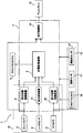
- FIG. 1 is a block diagram showing the configuration of each part of the proximity object warning / informing apparatus 1 according to the present embodiment
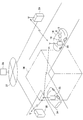
- FIG. 2 is a plan view of the automobile showing the location of each part.
- the proximity object warning / intelligence device 1 is an automobile, bicycle, person, animal, or the like (hereinafter referred to as “detection target”) that approaches the driving vehicle 14 from various directions, front, back, left, and right.
- detection target Surround stereo sound including a pair of left and right front cameras 2 and rear cameras 3, a radar sensor 4, a display 12 for displaying images captured by these cameras 2 and 3, and a plurality of speakers.
- a system 5 and a control unit 7 are provided. The control unit 7 is connected so that signals from the steering angle sensor 15, the shift position sensor 16, and the speed sensor 17 provided in the traveling system 14 a of the host vehicle 14 are input.
- Each camera 2 and 3 is composed of a CCD camera, a CMOS camera, or the like.
- the front camera 2 is a stereo camera attached to the left and right of the windshield 15 of the automobile 14.
- the front camera 2 recognizes a detection object in front of the automobile 14 in a three-dimensional manner and changes the angle of view of the camera. By widening the angle, it is possible to detect a detection object that protrudes from the front side.
- the rear camera 3 is attached to, for example, lower portions of the left and right door mirrors 16 in order to secure a rear view of the left and right sides of the automobile 14.
- These cameras 2 and 3 are configured to capture images at predetermined time intervals and output image data to the control unit 7.
- the display 12 displays images from the front camera 2 and the rear camera 3 based on a command from the control unit 7. As shown schematically in FIG. 3 by dividing the screen into four, the upper left and right display areas 12a and 12b display images taken by the left and right front cameras 2, respectively, Images displayed by the left and right rear cameras 3 are displayed in the display areas 12c and 12d, respectively. Further, by selecting any of the display areas 12a, 12b, 12c, and 12d, it is possible to display only the screen displayed in that area on the full screen.
- the radar sensor 4 is arranged at the center of the rear part of the automobile 14 in order to detect a region almost directly behind the automobile 14. According to the arrangement of the rear camera 3 in this example, the area behind the host vehicle 14 is covered with the radar sensor 4 because the area behind the host vehicle 14 is a blind spot.
- a millimeter wave radar, a microwave radar, a laser radar, an infrared sensor, an ultrasonic sensor, or the like is used as the radar sensor 4.
- a laser radar including a laser diode that generates laser light and a light receiving unit that receives the laser light is disposed.
- the surround stereo sound system 5 has a plurality of speakers 6 arranged in the passenger compartment so as to surround the driver.
- the control unit 7 forms a three-dimensional sound field according to the distance to the detection object detected by the cameras 2 and 3 and the radar sensor 4 and the position thereof by a surround method using the plurality of speakers 6. Control is performed to output sound from each speaker 6.
- a 5.1ch surround stereo sound system five center speakers are arranged in addition to the four speakers arranged on the right and left sides of the front seat and the right and left sides of the rear seat, respectively.
- three rear speakers are arranged in the same manner as in the front, but in this example, four of the two speakers are arranged at the front and the rear.
- the control unit 7 includes a microcomputer including a CPU, a ROM, and a RAM, and the CPU executes a program stored in the ROM, so that the acoustic control device 8, the front image recognition device 9, and the rear image recognition device are executed. 10. Processing as the rear detection device 11 and the display control device 13 is performed.
- the front image recognition device 9, the rear image recognition device 10, and the rear detection device 11 constitute a detection system 18 together with the cameras 2 and 3 and the radar sensor 4.
- the front image recognition device 9 and the rear image recognition device 10 respectively determine the approach of the detection target by performing image recognition processing on the captured images captured by the cameras 2 and 3. Therefore, the control unit 7 stores image features of detection objects such as various automobiles, bicycles, motorcycles such as motorcycles, and pedestrians in a reference data file (not shown) in advance, and a front image recognition device. 9 and the rear image recognition device 10 detect an object by detecting an image feature from a captured image.
- the acoustic control device 8 is three-dimensional to the driver so that an alarm sound can be heard from the approaching direction of the detection target detected by the detection system 18 to the own vehicle 14 by the plurality of speakers 6.
- the sound output by the surround system which forms a sound field is enabled.
- the memory of the sound control device 8 stores a plurality of alarm sound sources based on audio data having different sound quality, and the sound control device 8 selects the alarm sound source according to the situation in which the detected object to be detected approaches. By doing so, the sound quality of the alarm sound is changed and output.
- the sound quality in this case is represented by frequency, volume, or tone color (basic waveform shape).
- the front image recognition device 9 refers to the reference data file based on the image data output from the front camera 2, performs image recognition processing such as pattern recognition by a known image processing program, and detects the detection target object.
- the contour is recognized (step S1).
- the latest image data captured by the front camera 2 and the previous image data are sequentially compared, and the presence or absence of the approach is determined from the change in the size of the contour of the detected object to be recognized.
- the presence or absence of danger is judged (step S2). That is, in the case of the automobile 20 shown in FIG. 3, as shown in FIG. 6, the outline of the automobile 20 in the image (b) based on the latest image data is shown in the image (a) based on the previous image data.
- the ratio of the outline of the automobile 20 to the entire image exceeds the first predetermined value, it is determined that there is a risk of collision.
- a value of the ratio of the contour to the entire image is set in advance as the first predetermined value.
- a plurality of the first predetermined values are set according to the type of the detection object. For example, if the detection object is a person or a bicycle, the first predetermined value is smaller than that of the automobile. Also, a plurality of types of vehicles are set according to the size of the automobile, and the front image recognition device 9 uses a first corresponding to the large vehicle such as a bus or a truck to identify the outline of the object to be detected. A predetermined value can be selected and referenced.
- the front image recognition device 9 determines whether both the left and right front cameras 2 are capturing the automobile 20. (Step S3). As shown in FIG. 3, in this example, the automobile 20 is imaged only in the display area 12a, and it can be determined that there is a risk of the automobile 20 jumping out from the left side. Therefore, the front image recognition device 9 outputs a signal indicating that there is a danger from the front left side to the acoustic control device 8 (“NO” in step S3), and confirms that there is an approach of the automobile 20 on this side. A warning process is performed (step S4).
- the acoustic control device 8 selects a warning sound source, and a sound field that appeals to the driver's auditory sense that the warning sound resulting from this approaching according to the position of the vehicle 20 on the front left side. Is output to the surround stereo sound system 5.
- the sound control device 8 changes the sound quality of the alarm sound according to the distance that the automobile 20 approaches. For example, in order to change the sound quality by frequency, when the vehicle 20 is far away, the low frequency is set to a low warning sound, and as the vehicle approaches, the frequency is increased to a high level to make the driver feel dangerous. Like that. The volume is small when the automobile 20 is far away, and increases as the vehicle 20 approaches.
- ⁇ Alarm sound is not limited to continuous sound and may be generated intermittently.
- a tension can be brought to the driver by adjusting the interval according to the approach of the detection object. For example, as the automobile 20 approaches, the interval can be shortened so that the driver feels dangerous.
- the alarm control device 8 When the alarm sound is generated by a combination of sound quality depending on frequency and volume, and when the alarm sound is generated by intermittent sound, the alarm control device 8 generates an alarm sound that is more easily recognized by the driver by further combining intervals. It is good to configure so that it can.
- a plurality of speakers 6 are provided so as to surround the driver, and an alarm sound is output from each speaker 6 so as to form a three-dimensional sound field according to the distance and position of the object by the surround method. By doing so, it is possible to inform the driver of the position of the detection object with a sense of reality. Therefore, the driver can be strongly aware that there is a risk of the automobile 20 approaching and colliding.
- the sound control device 8 when the surround stereo sound system 5 is reproducing an audio sound source, the sound control device 8 is controlled to stop the reproduction and generate an alarm sound. On the contrary, the sound control device 8 drives the surround stereo sound system 5 to reproduce the alarm sound source when detecting the approach of the detection object while the surround stereo sound system 5 is not driven.
- the front image recognition device 9 similarly detects the contour of the car 21 captured by both the left and right front cameras 2 (step S1), and determines that the contour of the car 21 occupies the entire image when determining that the car 21 is approaching. If it exceeds the preset second predetermined value, it is determined that there is a risk of collision (“YES” in step S2).
- the second predetermined value is set as a second predetermined value in advance when the distance between the vehicle 21 and the vehicle 21 approaches a close distance where it is determined to be dangerous. Has been.
- a plurality of the second predetermined values are set in accordance with the type of the detection object, similarly to the first predetermined value described above.
- step S 5 a signal indicating that there is a danger is output to the sound control device 8 (“YES” in step S ⁇ b> 3), and from the front A process of warning that there is a risk is performed (step S5).
- step S5 the acoustic control device 8 generates a surround signal that obtains a sound field that audibly appeals to the driver that the alarm sound of the selected alarm sound source is approaching according to the position of the vehicle 21 ahead. Output to the surround stereo sound system 5. As a result, the driver can be made aware of the position of the vehicle 21 in front of the driver with a sense of reality.
- the automobile 21 is located directly in front of the own vehicle 14, but if the own vehicle 14 is a right-hand drive vehicle, the automobile 21 is located on the left front side. Provide the driver with a sound field that can be felt. That is, at this time, the front image recognition device 9 also recognizes the relative position between the automobile 21 and the own vehicle 14. For example, as shown in FIG. 7, the center line 11 of the own vehicle 14 and the automobile in the traveling direction with respect to each other. When the center line l2 of 21 coincides, a signal indicating that the automobile 21 is located in front of the host vehicle 14 is output to the acoustic control device 8. As a result, the driver 23 can visually recognize that the automobile 21 is located on the center line of the traveling direction of the host vehicle 14.
- the front image recognition device 9 When the front image recognition device 9 recognizes that the traveling position of the automobile 21 is on the driver seat side or the passenger seat side of the own vehicle 14, the front image recognition device 9 outputs a position signal corresponding thereto. Therefore, the acoustic control device 8 generates a surround signal corresponding to the travel position of the automobile 21 and outputs the surround signal to the surround stereo acoustic system 5, so that the driver can check the position of the automobile 21.
- the front image recognition device 9 calculates a separation interval value between the detection target and the own vehicle by detecting a shift between the two video signals from the pair of front cameras 2 that are stereo cameras, and the calculation is performed. It is also possible to measure the approach speed by calculating the differential value of the separation interval value, and to determine the danger from this approach speed information.
- the display control means 13 displays the images captured by the left and right front cameras 2 in the display areas 12a and 12b of the display, and the driver can visually confirm the danger from the front. .
- the rear image recognition device 10 performs image recognition processing with reference to the above-described reference data file based on the image data output from the rear camera 3, and is used for cars, pedestrians, and the like. Is recognized (step S10). Then, the latest image data captured by the rear camera 3 is compared with previous image data, and the presence or absence of the detection object is always determined from the change in the size of the contour of the recognized car or pedestrian. By determining, the danger by the presence or absence of the detection target object from back is judged (step S11).
- the left and right rear cameras 3 do not capture the same detection object, and whether or not another detection object approaches from the rear left side or the rear right side. Will be judged. Then, when the rear image recognition device 10 detects a detection object approaching from either or both of the left and right, the acoustic control device 8 generates a three-dimensional sound field according to the distance and position of the object by the surround method.
- the surround stereo sound system 5 is driven and controlled to form.
- the outline of the automobile 22 in the image based on the latest image data is the previous image data. If it is larger than the contour of the automobile 22 in the image, it is determined that the vehicle 14 is approaching from behind. Then, when the ratio of the contour of the automobile 22 to the entire image exceeds a preset third predetermined value, it is determined that there is a risk of collision (“YES” in step S11).
- the third predetermined value is similar to the first and second predetermined values described above, and the outline of the automobile 21 when the inter-vehicle distance from the automobile 22 is approached to a very close distance that is determined to be dangerous is displayed on the entire image. It is the value of the proportion.
- the acoustic control device 8 selects an alarm sound source and generates a sound field in which the alarm sound approaches from that direction.
- the obtained surround signal is output to the surround stereo sound system 5.
- the acoustic control device 8 drives the sense of perspective by controlling the frequency and volume of the alarm sound according to the distance from the approaching object to be detected, or changing the interval in the case of intermittent sound. Make people feel.
- the rear image recognition device 10 detects a detection object approaching from the right rear, and the sound control device 8 sends a surround signal that obtains a sound field according to the direction to the surround stereo sound system. 5 is output.
- the acoustic control device 8 selects the alarm sound source so that the tone colors of the alarm sounds from the left and right are different, so that the driver is approaching the vehicle from either the left or right side or from both sides. I can recognize that. Therefore, it is preferable to fix in advance the timbres of the alarm sound source used for the left and right respectively.
- the risk determined by the rear image recognition device 10 indicates the approach of the detection target in the adjacent lane to the own vehicle 14, but when the driver tries to turn the steering wheel in that direction,
- the sound control device 8 controls the surround stereo sound system 5 to generate another sound quality alarm in order to emphasize the danger.
- the acoustic control device 8 detects a steering operation by the steering angle sensor 15 (step S13).
- a change in the steering angle is detected by the steering operation (“YES” in step S13)
- the acoustic control device 8 warns that the lane in the steering direction is dangerous (step S14).
- the alarm sound selected by the sound control device 8 at this time and output to the surround stereo sound system 5 is an alarm that is distinguished from the alarm sound generated in step S12. It is preferred to use synthetic warning comments.
- a surround signal that obtains a sound field corresponding to the steering direction is also output to the surround stereo sound system 5, but it may be generated in place of the alarm generated in step S12 or both alarms. May be generated in piles.
- the operation of the rear image recognition apparatus 10 described above is performed when the shift position sensor 16 indicates that the gear position of the host vehicle 14 is in the forward gear from the shift position sensor 16.
- the rear image recognition device 10 detects the presence of the detection target and calculates the distance between them, and the acoustic control device 8 then detects the speed sensor 17.
- a surround signal that obtains a sound field corresponding to the reverse speed and the direction detected by is output to the surround stereo sound system 5 for warning. Accordingly, when the rear image recognition device 10 recognizes the presence of the detection object by the rear camera 3 when the host vehicle 14 is backing, the driver is shown a sound field corresponding to the corresponding direction, which is dangerous. Recognize the direction of sex.
- the rear camera 3 is disposed in a blind spot immediately behind the own vehicle, so the radar sensor 4 is disposed to detect a region almost directly behind the own vehicle 14.
- the rear detection device 11 performs a predetermined calculation based on the output of the radar sensor 4 and the speed signal from the speed sensor 17 of the host vehicle 14. It is a calculation means which performs. Therefore, when the rear detection device 11 calculates the inter-vehicle distance and the relative speed by this calculation, if the relative speed exceeds a predetermined value set in advance, there is an automobile approaching from behind the host vehicle 14. Is output to the acoustic control device 8.
- the sound control device 8 outputs a surround signal to the surround stereo sound system 5 so as to obtain a sound field approaching according to the position of the detection object immediately behind.
- the driver can be notified of the position of the vehicle 21 immediately behind the vehicle with a sense of presence.
- the acoustic control device 8 selects three kinds of alarm sounds having different timbres, and outputs a surround signal for obtaining a sound field approaching from the direction. Output to the surround stereo sound system 5. As a result, the alarm sound can make the driver aware of the position of the vehicle 21 in front of the driver with a sense of reality.
- Such a radar sensor 4 may be provided as a pair on the left and right sides for forward detection and backward detection, instead of the front camera 2 and the rear camera 3.
- the camera is not limited to the radar sensor 4, and a camera may be arranged at the center of the rear part of the automobile so that the rear side of the host vehicle 14 can be detected.
- the presence of the detection target approaching at high speed from behind can be detected by the rear image recognition device 10 in the same manner as in the case of the left and right rear cameras 3 described above.
- the rear image recognition device 10 outputs a signal indicating the approach of the vehicle from behind to the acoustic control device 8, so that the acoustic control device 8 selects a warning sound source and generates a sound field approaching from behind.
- the obtained surround signal is output to the surround stereo sound system 5.
- the acoustic control device 8 drives the sense of perspective by controlling the frequency and volume of the alarm sound according to the distance from the approaching object to be detected, or changing the interval in the case of intermittent sound. Make people feel.
- the detection system 18 is not limited to the one constituted by the front camera 2, the rear camera 3, the radar sensor 4, the front image recognition device 9, the rear image recognition device 10, and the rear detection device 11 in the above-described embodiment. .
- FIG. 8 shows an example of a detection system 18 using a satellite image processing system using a global positioning system (GPS).
- GPS global positioning system
- the detection system 18 detects the other vehicle 33 as a detection target object by performing short-range wireless communication with the other vehicle 33 located within an area within a certain short distance range from the own vehicle. be able to.
- the vehicle 14 includes a communication device 35 for wirelessly communicating with the outside in or separately from the control device 7 or the detection system 18.
- the short distance communication with the other vehicle 33 can recognize the other vehicle 33 even when the other vehicle 33 is behind a building or the like and cannot be detected by a camera or a radar sensor.
- each vehicle has its own current travel position, travel speed, acceleration / deceleration or braking operation, steering status, course and its change, in addition to the short-range wireless communication device capable of communication between vehicles.
- driving information such as a travel route can be acquired from various sensors mounted on the vehicle itself, the navigation device 32, and the like, and information can be provided to the other vehicle 33 in real time by short-range wireless communication. Thereby, for example, even when a parked vehicle is about to start by starting an engine, the behavior can be predicted.
- the driving information provided to the other vehicle 33 is selected as necessary and sufficient to detect the danger and to recognize the location and degree of the danger, which are the objects of the present invention.
- the detection system 18 determines, for example, the possibility of encountering or approaching the other vehicle during traveling, and calculates a separation interval value between the detection vehicle 18 and the own vehicle.
- the approach speed can be measured by calculating a differential value of the calculated separation interval value.
- the acoustic control device 8 obtains a sound field where the detection target approaches based on the approach direction, the separation distance, and the approach speed measured based on the driving information of the other vehicle 33 obtained in real time.
- the surround signal is output to the surround stereo sound system 5.
- the driving information acquired by the vehicle in this way is not only provided by direct communication between the vehicles, but also collected from each of the vehicles 14 and 34 to the cloud server 38 through the Internet 37, for example, as shown in FIG. It can also be processed as needed and downloaded from the cloud server 38 to each vehicle.
- the antenna 39 can be installed at a certain interval along the road, and driving information can be communicated between the vehicles 14 and 34 and the cloud server 38 through the antenna 39.
- the cloud server 38 may be installed for each area within a certain range.
- the detection system 18 obtains necessary driving information of the other vehicle 33 that can be a detection target from the cloud server 38 in the area where the host vehicle 14 is traveling, and similarly encounters or approaches the other vehicle 33 while traveling.
- the approaching speed can be measured by determining the possibility of performing the separation, calculating the separation interval value between the vehicle 14 and the own vehicle 14, and calculating the differential value of the calculated separation interval value.
- the acoustic control device 8 obtains a sound field in which the detection target object approaches based on the approach direction, the separation distance, and the approach speed measured based on the driving information of the other vehicle 33 obtained via the Internet.
- a surround signal is output to the surround stereo sound system 5.
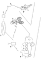
- FIG. 10 makes it possible to acquire information such as the position of the vehicle on the road and the driving situation using a chip-shaped communication device 40 (hereinafter referred to as “communication chip”) installed at certain intervals along the road.
- a chip-shaped communication device 40 hereinafter referred to as “communication chip”
- the communication chip 40 can be attached to, for example, a road surface installed on the road surface or the road shoulder, a road fence installed on the road center line or the lane boundary line, or various poles installed along the road shoulder or the traffic lane.
- the communication chip 40 has a function of wirelessly transmitting individual chip installation position information recorded in its own memory to the surroundings.
- a vehicle located in the vicinity of the communication chip 40 that is, a vehicle that passes or stops, receives the chip installation position information transmitted from the communication chip 40, and based on this information, the detection system 18 determines the position of the own vehicle 14. Can be recognized.
- the detection system 18 can more accurately grasp how the own vehicle 14 is traveling on the road by the installation pattern of the communication chip 40 on the road. For example, by detecting the positional relationship and the separation distance between the own vehicle 14 and each communication chip 40, whether the own vehicle 14 is running straight in the lane or not, whether it is determined from the road center line, the lane boundary line, or the shoulder It can be determined whether they are far away.
- the control device 7 predicts the presence / absence, degree and avoidance of danger, in addition to the approaching direction, separation distance and approaching speed of the other vehicle 33 previously detected by the detection system 18,
- the sound control device 8 outputs a surround signal to the surround stereo sound system 5 so as to obtain a sound field that makes the driver recognize the situation.
- the position information acquired by the vehicle by wireless communication with the communication chip 40 is very little if any from the cloud server 38 in real time by the short-range communication between the vehicles described above or via the Internet or the like. It can be provided to the other vehicle 33 with a short time delay.
- the transmission function of the communication chip 40 is such that a vehicle within a relatively short distance range can receive from the communication chip 40 so as not to cause interference with radio waves transmitted from another adjacent communication chip 40. Output is sufficient.
- the power supply of the communication chip 40 is secured by, for example, a battery that can be charged by solar power generation or the like, powered by a cable from an external power supply, or generated by radio waves transmitted from a vehicle traveling nearby. it can.
- the communication chip 40 can have a reception function for receiving information wirelessly in addition to or separately from the transmission function described above.
- a communication chip 40 detects that the vehicle has passed over or near it by receiving radio wave information transmitted by the vehicle.
- the radio wave information can include, for example, an identification code of the vehicle, optionally other vehicle information, current and future travel information, and the like.
- the travel information and the like obtained from the vehicle by the communication chip 40 is wirelessly transmitted to a server in the area via an antenna installed at a wider interval than the installation interval of the communication chip 40 along the road, for example. It can also be transmitted directly to the server via a cable connected to the communication chip 40 or wirelessly from a relay station connected to the cable to the server.
- the vehicle travel information from the communication chip 40 On the server side that has received the vehicle travel information from the communication chip 40, it is determined in what direction the vehicle is in which direction depending on the timing, time interval, etc. detected by the plurality of communication chips 40 continuously arranged along the road. You can see if you are traveling at speed. Thereby, even if the vehicle which is drive
- the detection system 18 obtains such traveling information of the other vehicle 33 from a server in the traveling area via a communication device mounted on the own vehicle 14. Then, the other vehicle 33 that can be a detection object is detected, the possibility of encountering or approaching the other vehicle 33 while traveling is determined, the separation interval value between the other vehicle 33 and the own vehicle 14 is calculated, and the calculated separation interval Measure the approach speed by calculating the differential value. Based on the approach direction, the separation distance, and the approach speed measured based on the travel information of the other vehicle 33 obtained from the road via the Internet in this way, the acoustic control device 8 uses the sound field where the detection target object approaches. Is output to the surround stereo sound system 5.
- FIG. 12 shows a system in which a wearer is recognized as a detection object by the detection system 18 when a person wears the card 47 in which such a communication chip is incorporated.
- the communication chip includes not only its own location information but also a specific identification code that can be seen to be worn by a person.
- the presence information of the person recognized in this way is obtained from the server 38 in the traveling area by the detection system 18 via the communication device mounted on the own vehicle 14. Then, the separation interval value between the wearer of the communication chip 40 and the own vehicle 14 is calculated, the approach speed is measured from the differential value of the calculated separation interval value, and the acoustic control device 8 is the person to be detected.
- a surround signal that obtains a sound field that approaches is output to the surround stereo sound system 5.
- the moving speed becomes faster than the normal walking speed.
- the movement speed of the wearer of the communication chip 40 becomes larger than a predetermined value or suddenly increases, it is added to the approaching direction to the own vehicle 14, the separation distance from the own vehicle 14, etc.
- the sound control device 8 outputs a surround signal to the surround stereo sound system 5 so as to obtain a sound field that allows the driver to recognize the situation.
- the danger that a person or a bicycle suddenly jumps out from behind the building can be detected in advance, and an accident can be avoided.
- the detection system 18 can be equipped with a 360 ° camera instead of or in addition to the front camera 2, the rear camera 3, or the radar sensor 4 of the above embodiment. As a result, it is possible to capture an all-around image centered on the host vehicle 14 and to visually grasp the situation around the entire periphery.
- the detection system 18 is a satellite image system, a short-range wireless communication between vehicles, a server system using the Internet, etc., or a detection system using a communication chip 40 installed on the road surface or by a person. Or it can be used in combination, and by using it in combination with the above-described radar sensor system or video camera system, it is possible to realize a more reliable proximity alarm device.
- the present invention relates to a proximity object alarming and detecting device that detects a detection object approaching from the surroundings of the own vehicle and generates a three-dimensional alarm sound according to the distance and position of the object by a surround method when the approach is detected. Has industrial applicability.
Landscapes
- Engineering & Computer Science (AREA)
- Physics & Mathematics (AREA)
- Acoustics & Sound (AREA)
- Signal Processing (AREA)
- Mechanical Engineering (AREA)
- General Physics & Mathematics (AREA)
- Otolaryngology (AREA)
- Health & Medical Sciences (AREA)
- Multimedia (AREA)
- Human Computer Interaction (AREA)
- Computer Vision & Pattern Recognition (AREA)
- Theoretical Computer Science (AREA)
- Traffic Control Systems (AREA)
- Fittings On The Vehicle Exterior For Carrying Loads, And Devices For Holding Or Mounting Articles (AREA)
- Stereophonic System (AREA)
- Circuit For Audible Band Transducer (AREA)
- Emergency Alarm Devices (AREA)
Abstract
The purpose of the present invention is to provide an approaching-body warning device that can make a driver aware, with a sense of presence, of the heading and position of a detection target that is approaching an own vehicle. The present invention is provided with a detection system 18 that comprises cameras 2, 3, a radar sensor 4, and the like that detect detection targets that approach an own vehicle 14 from the front, rear, left, or right. A plurality of speakers 6 are arranged inside the cabin of the own vehicle 14 so as to surround a driver. When the detection system 18 has determined that a detection target is approaching the own vehicle 14 from the front, rear, left, or right, a sound control device 8 outputs, to a surround stereo sound system 5, a warning sound that is based on a surround signal that is intended to achieve a sound field that corresponds to the direction of approach, and the driver is thereby provided with a sense of presence regarding the approach of the detection target.
Description
本発明は、自動車に搭載されて、自己車両に対してその周囲から接近してくる他の自動車、自転車等の移動物体がある場合に、その接近する物体の存在を運転者に警報報知する自動車の近接体警報知装置に関する。
The present invention is an automobile that is mounted on an automobile and alerts the driver of the presence of the approaching object when there is a moving object such as another automobile or bicycle that approaches the own vehicle from its surroundings. The present invention relates to a proximity object warning and intelligence device.
従来、この種の近接体警報知装置としては、自動車の左右の後側方の領域を2台のカメラで監視し、左右独立したそれぞれのモニタにリアルタイムで表示すると共に、自動車後部に設けたレーダセンサで後方からの接近自動車を監視して、それとの車間距離または相対速度あるいはその双方をもって危険な状態と判断したとき、例えば左側のモニタ画面に接近する自動車の存在による注意を促す画像をスーパーインポーズするものが知られている(例えば、特許文献1を参照)。そして、この特許文献1には、スーパーインポーズと共に、ステレオ方式の左右のスピーカで後方からの接近自動車の存在を認識する一方の側のスピーカから警報音を音声出力することが示されている。
Conventionally, as this kind of proximity object warning and intelligence device, the left and right rear side regions of the vehicle are monitored by two cameras and displayed in real time on the left and right independent monitors, and a radar provided at the rear of the vehicle. When an approaching vehicle from behind is monitored with a sensor and it is determined that the vehicle is in a dangerous state based on the distance between the vehicle and the relative speed or both, for example, an image that calls attention due to the presence of the vehicle approaching the monitor screen on the left side is superimposed. What is paused is known (see, for example, Patent Document 1). And this patent document 1 shows outputting a warning sound from the speaker of one side which recognizes the presence of the approaching vehicle from back with a stereo system left and right speaker with a superimpose.
また、進行方向の前方、特に両側方の障害物や自動車に関しては、レーダ波を照射して、その反射波から得られる物標情報に基づいて、危険を知らせる左右のランプとスピーカから注意を促すための報知情報を出力する装置が知られている(例えば、特許文献2を参照)。
Also, for obstacles and automobiles in the forward direction, especially on both sides, irradiate radar waves and call attention from the left and right lamps and speakers that inform the danger based on the target information obtained from the reflected waves. There is known an apparatus for outputting notification information for the purpose (see, for example, Patent Document 2).
しかしながら、上記の特許文献1及び2は、自己車両の周囲の危険性を検知したときスピーカから警報を発生するものの、危険の所在が自己車両の周囲のどの方向から、そしてどの程度の危険で迫っているのかを直ぐには認識できず、緊急時での判断が遅れることがある。
However, although the above Patent Documents 1 and 2 generate an alarm from the speaker when the danger around the own vehicle is detected, the danger is approaching from which direction around the own vehicle and at what degree of danger. It is not possible to recognize immediately whether it is present, and judgment in an emergency may be delayed.
上記課題に鑑み、本発明は、自己車両に接近する検知対象物の方向や位置を運転者に臨場感をもって認識させることができる近接体警報知装置の提供を目的としている。
In view of the above problems, an object of the present invention is to provide a proximity object warning / intelligence device that allows a driver to recognize the direction and position of a detection object approaching the own vehicle with a sense of presence.
上記課題を解決するために、本発明に係る近接体警報知装置は、運転する自己車両に対して前後左右の種々の方向から接近してくる自動車、自転車、人又は動物等(以下、「検知対象物」という)を検知する検知システムと、自己車両の室内に配置された複数台のスピーカを備えたサラウンドステレオ音響システムと、複数種類の警報音源信号を格納し、前記サラウンドステレオ音響システムを駆動制御する音響制御装置と、を有し、前記音響制御装置は、前記検知システムが当該自己車両に対して1又は複数の方向から接近してくる検知対象物を検知した時に、当該自己車両の運転者席位置において前記警報音源の内選択された一の警報音を前記検知システムが検知した検知対象物の当該自動車への接近方向から聞こえるように前記サラウンドステレオ音響システムの音量を駆動制御する、ことを特徴としている。
In order to solve the above-mentioned problem, the proximity alarm device according to the present invention is an automobile, bicycle, person, animal, or the like (hereinafter referred to as “detection”) that approaches the driving vehicle from various directions, front, back, left, and right. A detection system for detecting a target object), a surround stereo sound system having a plurality of speakers arranged in the interior of the own vehicle, and storing a plurality of types of alarm sound source signals to drive the surround stereo sound system. An acoustic control device that controls the driving of the host vehicle when the detection system detects a detection object approaching the host vehicle from one or more directions. One of the alarm sound sources selected from among the alarm sound sources at the position of the person's seat can be heard from the approaching direction of the detection target detected by the detection system to the vehicle. Drives and controls the volume of the command stereo sound system, it is characterized in that.
ここで前記検知システムは、レーダセンサシステム、1又は複数の映像撮像カメラシステム及び/又は衛星画像処理システムの1つ又は複数の組み合わせから成る。
Here, the detection system includes one or a combination of a radar sensor system, one or a plurality of video imaging camera systems, and / or a satellite image processing system.
そして、前記レーダセンサシステムは、ミリ波レーダ、マイクロ波レーダ、レーザーレーダ、赤外線センサ、超音波センサの何れか一つ又はその組み合わせであるとよい。この場合のレーダセンサシステムにおいては、前記検知対象物を検知するレーダセンサと、前記レーダセンサの検知出力と前記自己車両の速度から車間距離及び相対速度を演算して前記検知対象物の接近を判断する演算手段と、を備える。
The radar sensor system may be any one or a combination of millimeter wave radar, microwave radar, laser radar, infrared sensor, and ultrasonic sensor. In the radar sensor system in this case, a radar sensor for detecting the detection target object, and calculating an inter-vehicle distance and a relative speed from the detection output of the radar sensor and the speed of the own vehicle to determine the approach of the detection target object. Computing means.
一方、前記映像撮像カメラシステムは、自己車両の前方、後方、左側及び/又は右側の画像を撮像するよう配置された各々一対のカメラ装置と、前記カメラ装置が順次捉える撮像画像を画像認識処理することにより前記検知対象物の前方からの接近を判断する前方画像認識装置と、を含むことを特徴とする。
On the other hand, the video camera system performs image recognition processing on each pair of camera devices arranged to capture images of the front, rear, left side, and / or right side of the own vehicle, and captured images sequentially captured by the camera device. And a forward image recognition device that determines the approach of the detection object from the front.
このとき、前記映像撮像カメラシステムを構成する各々一対のカメラ装置は、所定の間隔を開けて配置され、当該一対のカメラ装置からの二つの映像信号のズレを検知することにより前記検知対象物と自己車両との離間間隔値を計算し、当該計算された離間間隔値の微分値を計算することにより接近スピードを測定する演算手段を有するとよい。
At this time, each pair of camera devices constituting the video imaging camera system is arranged at a predetermined interval, and the detection object is detected by detecting a shift between two video signals from the pair of camera devices. It is preferable to have a calculation means for measuring the approach speed by calculating a separation interval value with the own vehicle and calculating a differential value of the calculated separation interval value.
また、前記衛星画像処理システムは、地球を周回する衛星から送信されてくる当該車両周辺の画像データにより、検知対象物と自己車両との離間間隔値を計算し、当該計算された離間間隔値の微分値を計算することにより接近スピードを測定する演算手段を有する。
Further, the satellite image processing system calculates a separation interval value between the object to be detected and the own vehicle based on image data around the vehicle transmitted from a satellite orbiting the earth, and the calculated separation interval value is calculated. Computation means for measuring the approach speed by calculating the differential value is provided.
前記音響制御装置は、前記検知対象物が接近するにつれて前記警報音の周波数や音量を変化させるように前記サラウンドステレオ音響システムを制御する。これにより、運転者には、検知対象物が接近を強く認識される音場が提供される。
The sound control device controls the surround stereo sound system so as to change the frequency and volume of the alarm sound as the detection object approaches. Thus, the driver is provided with a sound field in which the detection target is strongly recognized as approaching.
また、前記音響制御装置は、インターバルを置いて前記警報音を断続的に発生させることができ、この場合、前記検知対象物の接近するにつれて前記インターバルが短くなるよう前記サラウンドステレオ音響システムを駆動制御する。これによっても、運転者には、検知対象物が接近を強く認識される音場が提供される。
Further, the sound control device can intermittently generate the alarm sound at intervals, and in this case, the surround stereo sound system is driven and controlled so that the interval becomes shorter as the detection object approaches. To do. This also provides the driver with a sound field in which the detection object is strongly recognized as approaching.
そして、前記音響制御装置は、それぞれ異なる方向から接近してくる前記検知対象物を検知した時に、その方向に応じて基本波形の異なる前記警報音源を選択して、同時に異なる音色が聞こえるように前記サラウンドステレオ音響システムを駆動制御するこれにより、運転者は、複数の方向から接近してくる前記検知対象物をそれぞれ個別に認識することができる。
And when the said sound control apparatus detects the said detection target approaching from each different direction, it selects the said alarm sound source from which a basic waveform differs according to the direction, and the said different sound is heard simultaneously. By driving and controlling the surround stereo sound system, the driver can individually recognize the detection objects approaching from a plurality of directions.
そして、前記音響制御装置は、前記サラウンドステレオ音響システムが音声再生中に前記検知システムが前記対象物の接近を検知した時、前記音声再生から前記警報音源の再生に切り換えて、逆に、前記サラウンドステレオ音響システムが非駆動中に前記検知システムが前記対象物の接近を検知した時、前記警報音源の再生のために前記サラウンドステレオ音響システムを駆動する。
Then, when the detection system detects the approach of the object during the sound reproduction of the surround stereo sound system, the sound control device switches from the sound reproduction to the reproduction of the alarm sound source, and conversely, When the detection system detects the approach of the object while the stereo sound system is not driven, the surround stereo sound system is driven to reproduce the alarm sound source.
また、前記音響制御装置は、前記検知システムが後方の左右の車線から前記検知対象物の接近を判断した時に自己車両が当該車線へ操舵されると、前記警報音源を発生するよう前記サラウンドステレオ音響システムを駆動制御する。これにより、危険を引き起こす運転操作を未然に防止できる。
The acoustic control device may be configured to generate the alarm sound source when the own vehicle is steered to the lane when the detection system determines that the detection target is approaching from the left and right lanes behind. Drive and control the system. As a result, it is possible to prevent a driving operation causing danger.
そして、前記音響制御装置は、自己車両のギアポジションがバックに入っている状態で前記検知システムが後方での前記検知対象物の存在を判断した時に、前記警報音源を発生するよう前記サラウンドステレオ音響システムを駆動制御する。これにより、バック走行時の安全を視覚的に確認できる。
Then, the sound control device is configured to generate the alarm sound source so that the alarm sound source is generated when the detection system determines the presence of the detection object behind in a state where the gear position of the own vehicle is in the back. Drive and control the system. Thereby, the safety at the time of back travel can be checked visually.
本発明による近接体警報知装置によれば、サラウンドステレオ音響システムによって、検知対象物が接近してくる方向及び検知対象物との間の距離に応じた遠近感を運転者に感じさせる音場を形成して警報音を出力するために、検知対象物が自己車両の至近距離に近づくと運転者に緊張感、警戒感を与えることができる。よって、運転者に対し臨場感をもって警告することができ、運転支援の効果をより高めることができる。
According to the proximity alarm device according to the present invention, the surround stereo sound system generates a sound field that makes the driver feel a sense of perspective according to the direction in which the detection target approaches and the distance to the detection target. In order to form and output an alarm sound, it is possible to give the driver a sense of tension and a sense of alertness when the detection object approaches a close distance of the own vehicle. Therefore, a warning can be given to the driver with a sense of reality, and the effect of driving support can be further enhanced.
本発明の実施の形態を図面に基づき説明する。図1は、本実施形態に係る近接体警報知装置1の各部の構成をブロック図で示し、図2は各部の配置場所を自動車の平面図で示している。これら図で示すように、近接体警報知装置1は、運転する自己車両14に対して前後左右の種々の方向から接近してくる自動車、自転車、人又は動物等(以下、「検知対象物」という)を検知するよう設けられるそれぞれ左右一対のフロントカメラ2及びリアカメラ3と、レーダセンサ4と、これらカメラ2、3による撮像画像を表示するディスプレイ12と、複数台のスピーカから成るサラウンドステレオ音響システム5と、制御部7とを備えている。また、制御部7は、自己車両14の走行系14aに備えられている操舵角センサ15、シフトポジションセンサ16及び速度センサ17からの各信号がそれぞれ入力するように接続されている。
Embodiments of the present invention will be described with reference to the drawings. FIG. 1 is a block diagram showing the configuration of each part of the proximity object warning / informing apparatus 1 according to the present embodiment, and FIG. 2 is a plan view of the automobile showing the location of each part. As shown in these drawings, the proximity object warning / intelligence device 1 is an automobile, bicycle, person, animal, or the like (hereinafter referred to as “detection target”) that approaches the driving vehicle 14 from various directions, front, back, left, and right. Surround stereo sound including a pair of left and right front cameras 2 and rear cameras 3, a radar sensor 4, a display 12 for displaying images captured by these cameras 2 and 3, and a plurality of speakers. A system 5 and a control unit 7 are provided. The control unit 7 is connected so that signals from the steering angle sensor 15, the shift position sensor 16, and the speed sensor 17 provided in the traveling system 14 a of the host vehicle 14 are input.
各カメラ2、3は、CCDカメラやCMOSカメラ等により構成されている。フロントカメラ2は、図2で示すように、自動車14のフロントガラス15の左右に取り付けられるステレオカメラであって、自動車14の前方の検知対象物を立体的に認識すると共に、カメラの画角を広角化することで前方の側方から飛び出してくる検知対象物も検知できるようにしている。また、リアカメラ3は、自動車14の左右の側部の後方視界を確保するために、例えば、左右のドアミラー16の下部にそれぞれ取り付けられる。そして、これらのカメラ2、3は予め定められた時間間隔で撮像し画像データを制御部7に出力するように構成されている。
Each camera 2 and 3 is composed of a CCD camera, a CMOS camera, or the like. As shown in FIG. 2, the front camera 2 is a stereo camera attached to the left and right of the windshield 15 of the automobile 14. The front camera 2 recognizes a detection object in front of the automobile 14 in a three-dimensional manner and changes the angle of view of the camera. By widening the angle, it is possible to detect a detection object that protrudes from the front side. In addition, the rear camera 3 is attached to, for example, lower portions of the left and right door mirrors 16 in order to secure a rear view of the left and right sides of the automobile 14. These cameras 2 and 3 are configured to capture images at predetermined time intervals and output image data to the control unit 7.
ディスプレイ12は、制御部7からの指令に基づいてフロントカメラ2及びリアカメラ3からの映像を表示する。表示は、画面を4分割して図3で模式的に示すように、上段の左右の表示エリア12a、12bには、それぞれ左と右のフロントカメラ2による撮像画像を表示し、下段の左右の表示エリア12c、12dには、それぞれ左と右のリアカメラ3による撮像画像を表示する。また、何れかの表示エリア12a、12b、12c、12dを選択することで、そのエリアに表示している画面のみを全画面で表示することもできる。
The display 12 displays images from the front camera 2 and the rear camera 3 based on a command from the control unit 7. As shown schematically in FIG. 3 by dividing the screen into four, the upper left and right display areas 12a and 12b display images taken by the left and right front cameras 2, respectively, Images displayed by the left and right rear cameras 3 are displayed in the display areas 12c and 12d, respectively. Further, by selecting any of the display areas 12a, 12b, 12c, and 12d, it is possible to display only the screen displayed in that area on the full screen.
レーダセンサ4は、自動車14のほぼ真後ろの領域を検知するために、自動車14の後部中央に配置されている。本例でのリアカメラ3の配置によれば、自己車両14の真後ろは死角となるために、レーダセンサ4を用いることで真後ろの領域をカバーしている。レーダセンサ4には、ミリ波レーダ、マイクロ波レーダ、レーザーレーダ、赤外線センサ、超音波センサなどが使用される。本例では、レーザー光を発生させるレーザーダイオードと、レーザー光を受光する受光部とから構成されるレーザーレーダを配置している。
The radar sensor 4 is arranged at the center of the rear part of the automobile 14 in order to detect a region almost directly behind the automobile 14. According to the arrangement of the rear camera 3 in this example, the area behind the host vehicle 14 is covered with the radar sensor 4 because the area behind the host vehicle 14 is a blind spot. As the radar sensor 4, a millimeter wave radar, a microwave radar, a laser radar, an infrared sensor, an ultrasonic sensor, or the like is used. In this example, a laser radar including a laser diode that generates laser light and a light receiving unit that receives the laser light is disposed.
サラウンドステレオ音響システム5は、車室内に複数台のスピーカ6を、運転者を取囲むように配置している。制御部7は、これら複数のスピーカ6を用いたサラウンド方式により、カメラ2,3やレーダセンサ4が検知した検知対象物との距離やその位置に応じた立体的な音場を形成するように各スピーカ6から音声を出力させるよう制御する。なお、5.1chサラウンドステレオ音響システムを構築する場合、前部座席の右側及び左側と、後部座席の右側及び左側とにそれぞれ配置された4個のスピーカに加えてセンタースピーカの5台を配置し、6.1chサラウンドステレオ音響システムでは、リアスピーカを前方と同じように3台配置するが、本例ではフロントとリアに2台ずつの4台を配置した例を示している。
The surround stereo sound system 5 has a plurality of speakers 6 arranged in the passenger compartment so as to surround the driver. The control unit 7 forms a three-dimensional sound field according to the distance to the detection object detected by the cameras 2 and 3 and the radar sensor 4 and the position thereof by a surround method using the plurality of speakers 6. Control is performed to output sound from each speaker 6. When constructing a 5.1ch surround stereo sound system, five center speakers are arranged in addition to the four speakers arranged on the right and left sides of the front seat and the right and left sides of the rear seat, respectively. In the 6.1ch surround stereo sound system, three rear speakers are arranged in the same manner as in the front, but in this example, four of the two speakers are arranged at the front and the rear.
制御部7は、CPU、ROM、RAMを含むマイクロコンピュータで構成されて、CPUは、ROMに格納されているプログラムを実行することで、音響制御装置8、前方画像認識装置9、後方画像認識装置10、後方検知装置11及び表示制御装置13としての処理を行う。そして、前方画像認識装置9、後方画像認識装置10及び後方検知装置11は、カメラ2、3やレーダセンサ4と共に検知システム18を構成する。
The control unit 7 includes a microcomputer including a CPU, a ROM, and a RAM, and the CPU executes a program stored in the ROM, so that the acoustic control device 8, the front image recognition device 9, and the rear image recognition device are executed. 10. Processing as the rear detection device 11 and the display control device 13 is performed. The front image recognition device 9, the rear image recognition device 10, and the rear detection device 11 constitute a detection system 18 together with the cameras 2 and 3 and the radar sensor 4.
前方画像認識装置9及び後方画像認識装置10は、それぞれのカメラ2,3が捉える撮像画像を画像認識処理することで、検知対象物の接近をそれぞれ判断する。よって、制御部7は、各種の自動車や自転車、およびオートバイなどの自動二輪車、歩行者などの検知対象物の画像特徴を基準データファイル(図示せず)に予め記憶していて、前方画像認識装置9及び後方画像認識装置10は、撮像画像から画像特徴を検出することで対象物を検知する。
The front image recognition device 9 and the rear image recognition device 10 respectively determine the approach of the detection target by performing image recognition processing on the captured images captured by the cameras 2 and 3. Therefore, the control unit 7 stores image features of detection objects such as various automobiles, bicycles, motorcycles such as motorcycles, and pedestrians in a reference data file (not shown) in advance, and a front image recognition device. 9 and the rear image recognition device 10 detect an object by detecting an image feature from a captured image.
音響制御装置8は、上記したように複数台のスピーカ6によって、検知システム18が検知した検知対象物の自己車両14への接近方向から警報音が聞こえるように、運転者に対して立体的な音場を形成するサラウンド方式による音声出力を可能としている。音響制御装置8のメモリには、音質の相違する音声データによる複数の警報音源が記憶されており、音響制御装置8は、検出された検知対象物が接近する状況に応じて、警報音源を選択することにより、警報音の音質を変えて出力するようになっている。この場合の音質は、周波数や音量、または音色(基本波形の形)で表わされる。
As described above, the acoustic control device 8 is three-dimensional to the driver so that an alarm sound can be heard from the approaching direction of the detection target detected by the detection system 18 to the own vehicle 14 by the plurality of speakers 6. The sound output by the surround system which forms a sound field is enabled. The memory of the sound control device 8 stores a plurality of alarm sound sources based on audio data having different sound quality, and the sound control device 8 selects the alarm sound source according to the situation in which the detected object to be detected approaches. By doing so, the sound quality of the alarm sound is changed and output. The sound quality in this case is represented by frequency, volume, or tone color (basic waveform shape).
制御部7の詳細を説明しながら、以下、近接体警報知装置1の動作を説明する。
The operation of the proximity alarm device 1 will be described below while explaining details of the control unit 7.
先ず、図4のフローチャートによって、前方画像認識装置9による前方検知処理動作を説明する。前方画像認識装置9は、フロントカメラ2から出力される画像データをもとに、上記基準データファイルを参照して、既知の画像処理プログラムによるパターン認識等の画像認識処理を行い、検知対象物の輪郭を認識する(ステップS1)。
First, the forward detection processing operation by the forward image recognition device 9 will be described with reference to the flowchart of FIG. The front image recognition device 9 refers to the reference data file based on the image data output from the front camera 2, performs image recognition processing such as pattern recognition by a known image processing program, and detects the detection target object. The contour is recognized (step S1).
具体的には、フロントカメラ2によって撮像された最新の画像データとこれ以前の画像データとを順次比較して、認識している検知対象物の輪郭の大きさの変化からその接近の有無を判定することで、危険性の有無を判断する(ステップS2)。すなわち、図3に示されている自動車20で説明すれば、図6で示すように最新の画像データによる画像(b)での自動車20の輪郭が、これ以前の画像データによる画像(a)での自動車20の輪郭よりも大きいときには、自動車20は自己車両14に接近していると判断し、逆に、小さいときには遠ざかっていると判断する。そして、接近していると判断したとき、自動車20の輪郭が画像全体に占める割合が第1の所定値を超えている場合には、衝突の危険性が有ると判定する。
Specifically, the latest image data captured by the front camera 2 and the previous image data are sequentially compared, and the presence or absence of the approach is determined from the change in the size of the contour of the detected object to be recognized. By doing so, the presence or absence of danger is judged (step S2). That is, in the case of the automobile 20 shown in FIG. 3, as shown in FIG. 6, the outline of the automobile 20 in the image (b) based on the latest image data is shown in the image (a) based on the previous image data. When it is larger than the outline of the automobile 20, it is judged that the automobile 20 is approaching the own vehicle 14, and conversely, when it is smaller, it is judged that it is moving away. When it is determined that the vehicle is approaching, if the ratio of the outline of the automobile 20 to the entire image exceeds the first predetermined value, it is determined that there is a risk of collision.
画像に占める自動車20の輪郭が大きくなるということは、その分、自己車両14と自動車20との距離が縮まることであり、自動車20が危険と判断される至近距離まで接近したとき、自動車20の輪郭が画像全体に占める割合の値が予め第1の所定値として設定されている。この第1の所定値は、検知対象物の種類に応じて複数設定されており、例えば、検知対象物が人や自転車であれば、第1の所定値は自動車と比べて小さいものとなる。また、自動車でもそのサイズに応じて複数通り設定されており、前方画像認識装置9は、検知対象物の輪郭の形状からバスやトラック等の大型車を識別するために、それに応じた第1の所定値を選択して参照することができる。
The fact that the outline of the automobile 20 occupies the image is increased, and accordingly, the distance between the own vehicle 14 and the automobile 20 is reduced, and when the automobile 20 approaches a close distance that is determined to be dangerous, A value of the ratio of the contour to the entire image is set in advance as the first predetermined value. A plurality of the first predetermined values are set according to the type of the detection object. For example, if the detection object is a person or a bicycle, the first predetermined value is smaller than that of the automobile. Also, a plurality of types of vehicles are set according to the size of the automobile, and the front image recognition device 9 uses a first corresponding to the large vehicle such as a bus or a truck to identify the outline of the object to be detected. A predetermined value can be selected and referenced.
図4のフローチャートの説明に戻って、前方画像認識装置9は、衝突の危険性が有ると判定すると(ステップS2の「YES」)、左右両方のフロントカメラ2が自動車20を捉えているかを判別する(ステップS3)。図3で示すように、この例では自動車20は表示エリア12aにしか撮像されておらず、左サイドからの自動車20の飛出しの危険性があることが判別できる。よって、前方画像認識装置9は、前方左サイドからの危険があることを示す信号を音響制御装置8に出力し(ステップS3の「NO」)、このサイドでの自動車20の接近があることを警告する処理を行う(ステップS4)。
Returning to the description of the flowchart of FIG. 4, when the front image recognition device 9 determines that there is a risk of collision (“YES” in step S <b> 2), it determines whether both the left and right front cameras 2 are capturing the automobile 20. (Step S3). As shown in FIG. 3, in this example, the automobile 20 is imaged only in the display area 12a, and it can be determined that there is a risk of the automobile 20 jumping out from the left side. Therefore, the front image recognition device 9 outputs a signal indicating that there is a danger from the front left side to the acoustic control device 8 (“NO” in step S3), and confirms that there is an approach of the automobile 20 on this side. A warning process is performed (step S4).
ステップS4での処理において、音響制御装置8は、警報音源を選択して、これによる警報音が前方左サイドの自動車20の位置に応じて接近してくる感覚を運転者の聴覚に訴える音場を得るようなサラウンド信号をサラウンドステレオ音響システム5に出力する。
In the process in step S4, the acoustic control device 8 selects a warning sound source, and a sound field that appeals to the driver's auditory sense that the warning sound resulting from this approaching according to the position of the vehicle 20 on the front left side. Is output to the surround stereo sound system 5.
このとき、音響制御装置8は、自動車20が接近してくる距離に応じて、警報音の音質を変えていく。例えば、周波数で音質を変えるには、自動車20が遠くにあるときには低周波数とすることで低音の警報音とし、接近するにつれて、周波数を上げて高音とすることによって、運転者に危険を感じさせるようにする。また、音量は、自動車20が遠くにあるときには小さく、接近するにつれて音量を増大させる。
At this time, the sound control device 8 changes the sound quality of the alarm sound according to the distance that the automobile 20 approaches. For example, in order to change the sound quality by frequency, when the vehicle 20 is far away, the low frequency is set to a low warning sound, and as the vehicle approaches, the frequency is increased to a high level to make the driver feel dangerous. Like that. The volume is small when the automobile 20 is far away, and increases as the vehicle 20 approaches.
警報音は、連続した音とは限らず、断続的に発生させてもよい。その場合、検知対象物の接近に応じてインターバルを調整することにより、運転者には緊張感をもたらすことができる。例えば、自動車20が接近するにつれて、インターバルを短くすることで運転者が危険を感じるようにすることもできる。
警報 Alarm sound is not limited to continuous sound and may be generated intermittently. In that case, a tension can be brought to the driver by adjusting the interval according to the approach of the detection object. For example, as the automobile 20 approaches, the interval can be shortened so that the driver feels dangerous.
そして、警報音は、周波数や音量による音質の組み合わせ、さらに警報音を断続した音で発生させるときには、さらにインターバルを組み合わせることで、音響制御装置8において、運転者がより認識しやすい警報音を生成できるように構成するとよい。
When the alarm sound is generated by a combination of sound quality depending on frequency and volume, and when the alarm sound is generated by intermittent sound, the alarm control device 8 generates an alarm sound that is more easily recognized by the driver by further combining intervals. It is good to configure so that it can.
これにより、対象物との距離の大小に応じた遠近感を運転者に感じさせることが可能となり、運転者に対して、より現実的且つ直感的な報知を行うことが可能となる。しかも、複数個のスピーカ6を、運転者を取囲むように設けて、サラウンド方式により、対象物の距離や位置に応じた立体的な音場を形成するように各スピーカ6から警報音を出力させるようにしたことにより、検知対象物の位置なども、運転者に対し臨場感をもって知らせることができる。よって、運転者は、自動車20が接近してきて衝突する危険性のあることを強く意識することができる。
This makes it possible for the driver to feel a sense of perspective according to the distance from the object, making it possible to provide more realistic and intuitive notification to the driver. In addition, a plurality of speakers 6 are provided so as to surround the driver, and an alarm sound is output from each speaker 6 so as to form a three-dimensional sound field according to the distance and position of the object by the surround method. By doing so, it is possible to inform the driver of the position of the detection object with a sense of reality. Therefore, the driver can be strongly aware that there is a risk of the automobile 20 approaching and colliding.
このとき、サラウンドステレオ音響システム5がオーディオ音源を再生している場合には、再生を中断して警報音を発するように音響制御装置8によって制御される。逆に、音響制御装置8は、サラウンドステレオ音響システム5が非駆動中に検知対象物の接近を検知した時、前記警報音源の再生のためにサラウンドステレオ音響システム5を駆動する。
At this time, when the surround stereo sound system 5 is reproducing an audio sound source, the sound control device 8 is controlled to stop the reproduction and generate an alarm sound. On the contrary, the sound control device 8 drives the surround stereo sound system 5 to reproduce the alarm sound source when detecting the approach of the detection object while the surround stereo sound system 5 is not driven.
前方画像認識装置9は、左右両方のフロントカメラ2が捉える自動車21についても同様にして輪郭を検出し(ステップS1)、接近していると判断したとき、自動車21の輪郭が画像全体に占める割合が予め設定されている第2の所定値を超えている場合には、衝突の危険性が有ると判定する(ステップS2の「YES」)。この場合の第2の所定値は、自動車21との車間距離が危険と判断される至近距離まで接近したとき、自動車21の輪郭が画像全体に占める割合の値が予め第2の所定値として設定されている。この第2の所定値も、上記した第1の所定値と同様、検知対象物の種類に応じて複数設定されている。
The front image recognition device 9 similarly detects the contour of the car 21 captured by both the left and right front cameras 2 (step S1), and determines that the contour of the car 21 occupies the entire image when determining that the car 21 is approaching. If it exceeds the preset second predetermined value, it is determined that there is a risk of collision (“YES” in step S2). In this case, the second predetermined value is set as a second predetermined value in advance when the distance between the vehicle 21 and the vehicle 21 approaches a close distance where it is determined to be dangerous. Has been. A plurality of the second predetermined values are set in accordance with the type of the detection object, similarly to the first predetermined value described above.
しかし、自動車21の場合は、左右両方のフロントカメラ2で捉えられているために、危険性があることを示す信号を音響制御装置8に出力し(ステップS3の「YES」)、正面からの危険性があることを警告する処理が行われる(ステップS5)。
However, in the case of the automobile 21, since it is captured by both the left and right front cameras 2, a signal indicating that there is a danger is output to the sound control device 8 (“YES” in step S <b> 3), and from the front A process of warning that there is a risk is performed (step S5).
ステップS5の処理では、音響制御装置8は、選択した警報音源の警報音が前方の自動車21の位置に応じて接近してくる感覚を運転者に聴覚で訴える音場を得るようなサラウンド信号をサラウンドステレオ音響システム5に出力する。これにより、前方の自動車21の位置などを、運転者に対し臨場感をもって意識させることができる。
In the process of step S5, the acoustic control device 8 generates a surround signal that obtains a sound field that audibly appeals to the driver that the alarm sound of the selected alarm sound source is approaching according to the position of the vehicle 21 ahead. Output to the surround stereo sound system 5. As a result, the driver can be made aware of the position of the vehicle 21 in front of the driver with a sense of reality.
自動車21は、自己車両14に対しては真正面に位置するが、自己車両14が右ハンドル車であると運転者からは左前方に位置しているために、音響制御装置8は、このことを感じられる音場を運転者に提供する。すなわち、このとき前方画像認識装置9は、自動車21と自己車両14との相対位置も認識しており、例えば、図7で示すように、互いに進行方向での自己車両14の中心線l1と自動車21の中心線l2とが一致しているときには、自動車21が自己車両14の真正面に位置していることを示す信号を音響制御装置8に出力する。これにより、運転者23は自己車両14の進行方向の中心線上に自動車21が位置していることを聴覚上で認識できる。
The automobile 21 is located directly in front of the own vehicle 14, but if the own vehicle 14 is a right-hand drive vehicle, the automobile 21 is located on the left front side. Provide the driver with a sound field that can be felt. That is, at this time, the front image recognition device 9 also recognizes the relative position between the automobile 21 and the own vehicle 14. For example, as shown in FIG. 7, the center line 11 of the own vehicle 14 and the automobile in the traveling direction with respect to each other. When the center line l2 of 21 coincides, a signal indicating that the automobile 21 is located in front of the host vehicle 14 is output to the acoustic control device 8. As a result, the driver 23 can visually recognize that the automobile 21 is located on the center line of the traveling direction of the host vehicle 14.
そして、前方画像認識装置9は、自動車21の走行位置が自己車両14の運転席側又は助手席側にあることを認識したときには、それに応じた位置信号を出力する。したがって、音響制御装置8が自動車21の走行位置に応じたサラウンド信号を生成して、サラウンドステレオ音響システム5に出力することで、運転者は、自動車21の位置を確認できる。
When the front image recognition device 9 recognizes that the traveling position of the automobile 21 is on the driver seat side or the passenger seat side of the own vehicle 14, the front image recognition device 9 outputs a position signal corresponding thereto. Therefore, the acoustic control device 8 generates a surround signal corresponding to the travel position of the automobile 21 and outputs the surround signal to the surround stereo acoustic system 5, so that the driver can check the position of the automobile 21.
また、前方画像認識装置9は、ステレオカメラである一対のフロントカメラ2からの二つの映像信号のズレを検知することにより検知対象物と自己車両との離間間隔値を計算し、当該計算された離間間隔値の微分値を計算することにより接近スピードを測定し、この接近スピード情報からも危険性を判断することも可能である。
Further, the front image recognition device 9 calculates a separation interval value between the detection target and the own vehicle by detecting a shift between the two video signals from the pair of front cameras 2 that are stereo cameras, and the calculation is performed. It is also possible to measure the approach speed by calculating the differential value of the separation interval value, and to determine the danger from this approach speed information.
そして、表示制御手段13は、左右のフロントカメラ2が捉えた画像をディスプレイの表示エリア12a、12bに表示させており、運転者は、視覚的にも前方からの危険性を確認することができる。
The display control means 13 displays the images captured by the left and right front cameras 2 in the display areas 12a and 12b of the display, and the driver can visually confirm the danger from the front. .
次に、図5のフローチャートによって、後方画像認識装置10による後方検知の処理動作を説明する。後方画像認識装置10は、前方画像認識装置9と同様に、リアカメラ3から出力される画像データをもとに、上記の基準データファイルを参照して画像認識処理を行い、自動車や歩行者などの輪郭を認識する(ステップS10)。そして、リアカメラ3によって撮像された最新の画像データとこれ以前の画像データとを比較して、認識している自動車や歩行者の輪郭の大きさの変化から検知対象物の接近の有無を常に判定することで、後方からの検知対象物の有無による危険性を判断する(ステップS11)。
Next, the processing operation of the rear detection by the rear image recognition apparatus 10 will be described with reference to the flowchart of FIG. Similar to the front image recognition device 9, the rear image recognition device 10 performs image recognition processing with reference to the above-described reference data file based on the image data output from the rear camera 3, and is used for cars, pedestrians, and the like. Is recognized (step S10). Then, the latest image data captured by the rear camera 3 is compared with previous image data, and the presence or absence of the detection object is always determined from the change in the size of the contour of the recognized car or pedestrian. By determining, the danger by the presence or absence of the detection target object from back is judged (step S11).
本例でのリアカメラ3は、ドアミラーに取り付けられているために、左右のリアカメラ3で同一の検知対象物は撮像されず、後方左側又は後方右側からそれぞれ別の検知対象物の接近の有無を判断することになる。そして、後方画像認識装置10は、左右の何れか又は両方から接近する検知対象物を検知すると、音響制御装置8は、サラウンド方式により、対象物の距離や位置に応じた立体的な音場を形成するようにサラウンドステレオ音響システム5を駆動制御する。
Since the rear camera 3 in this example is attached to the door mirror, the left and right rear cameras 3 do not capture the same detection object, and whether or not another detection object approaches from the rear left side or the rear right side. Will be judged. Then, when the rear image recognition device 10 detects a detection object approaching from either or both of the left and right, the acoustic control device 8 generates a three-dimensional sound field according to the distance and position of the object by the surround method. The surround stereo sound system 5 is driven and controlled to form.
後方画像認識装置10は、例えば、図3の表示エリア12cに撮像されている自動車22を検知対象物として捉えたとき、最新の画像データによる画像での自動車22の輪郭が、これ以前の画像データによる画像での自動車22の輪郭より大きいときには自己車両14に後方から接近していると判断する。そして、自動車22の輪郭が画像全体に占める割合が予め設定されている第3の所定値を超えている場合には、衝突の危険性が有ると判定する(ステップS11の「YES」)。なお、第3の所定値は、上記した第1及び第2の所定値と同様に、自動車22との車間距離が危険と判断される至近距離まで接近したときの自動車21の輪郭が画像全体に占める割合の値である。
For example, when the rear image recognition apparatus 10 captures the automobile 22 imaged in the display area 12c of FIG. 3 as a detection target, the outline of the automobile 22 in the image based on the latest image data is the previous image data. If it is larger than the contour of the automobile 22 in the image, it is determined that the vehicle 14 is approaching from behind. Then, when the ratio of the contour of the automobile 22 to the entire image exceeds a preset third predetermined value, it is determined that there is a risk of collision (“YES” in step S11). Note that the third predetermined value is similar to the first and second predetermined values described above, and the outline of the automobile 21 when the inter-vehicle distance from the automobile 22 is approached to a very close distance that is determined to be dangerous is displayed on the entire image. It is the value of the proportion.
後方画像認識装置10が左後方から接近する自動車22が接近していると判断すると、音響制御装置8は、警報音源を選択して、それによる警報音がその方向から接近してくる音場を得るようなサラウンド信号をサラウンドステレオ音響システム5に出力する。そして、音響制御装置8は、接近する検知対象物との距離の大小に応じて警報音の周波数や音量、また断続音の場合にはインターバルを変えていく制御を行なうことで、遠近感を運転者に感じさせる。
When the rear image recognition device 10 determines that the vehicle 22 approaching from the left rear is approaching, the acoustic control device 8 selects an alarm sound source and generates a sound field in which the alarm sound approaches from that direction. The obtained surround signal is output to the surround stereo sound system 5. The acoustic control device 8 drives the sense of perspective by controlling the frequency and volume of the alarm sound according to the distance from the approaching object to be detected, or changing the interval in the case of intermittent sound. Make people feel.
これにより、左後方からの自動車22の位置などを、運転者に対し臨場感をもって知らせることができる。この場合、後方画像認識装置10が右後方から接近する検知対象物を検知した時も同様であり、音響制御装置8は、その方向に応じた音場を得るようなサラウンド信号をサラウンドステレオ音響システム5に出力する。この場合に、音響制御装置8は、左右それぞれからの警報音の音色が異なるように警報音源を選択することで、運転者は、左右いずれの側方から又は両側方から自動車が接近していることを認識できる。したがって、左右でそれぞれ使用する警報音源の音色は区別したものに予め固定しておくのがよい。
This makes it possible to inform the driver of the position of the car 22 from the left rear with a sense of presence. In this case, the same is true when the rear image recognition device 10 detects a detection object approaching from the right rear, and the sound control device 8 sends a surround signal that obtains a sound field according to the direction to the surround stereo sound system. 5 is output. In this case, the acoustic control device 8 selects the alarm sound source so that the tone colors of the alarm sounds from the left and right are different, so that the driver is approaching the vehicle from either the left or right side or from both sides. I can recognize that. Therefore, it is preferable to fix in advance the timbres of the alarm sound source used for the left and right respectively.
また、後方画像認識装置10で判定される危険性は、自己車両14に対する隣の車線での検知対象物の接近を示すものであるが、運転者が、その方向にハンドルを切ろうとしたとき、音響制御装置8は、危険性を強調するために、さらに別の音質の警報を発生するようサラウンドステレオ音響システム5を制御する。
The risk determined by the rear image recognition device 10 indicates the approach of the detection target in the adjacent lane to the own vehicle 14, but when the driver tries to turn the steering wheel in that direction, The sound control device 8 controls the surround stereo sound system 5 to generate another sound quality alarm in order to emphasize the danger.
このとき音響制御装置8は、操舵角センサ15によってハンドル操作を検知する(ステップS13)。そして、ステアリング操作により操舵角の変化を検知したときには(ステップS13の「YES」)、音響制御装置8は操舵方向の車線が危険であることを警告する(ステップS14)。このときの音響制御装置8が選択してサラウンドステレオ音響システム5に出力する警報音は、ステップS12で発生している警報音とは区別した警報となるが、明確に運転者に知らせるには音声合成による警告コメントを使用するのが好ましい。この場合の警告音も操舵方向に応じた音場を得るようなサラウンド信号をサラウンドステレオ音響システム5に出力するが、ステップS12で発生している警報に変えて発生させても、或いは両方の警報を重ねて発生させてもよい。
At this time, the acoustic control device 8 detects a steering operation by the steering angle sensor 15 (step S13). When a change in the steering angle is detected by the steering operation (“YES” in step S13), the acoustic control device 8 warns that the lane in the steering direction is dangerous (step S14). The alarm sound selected by the sound control device 8 at this time and output to the surround stereo sound system 5 is an alarm that is distinguished from the alarm sound generated in step S12. It is preferred to use synthetic warning comments. In this case, a surround signal that obtains a sound field corresponding to the steering direction is also output to the surround stereo sound system 5, but it may be generated in place of the alarm generated in step S12 or both alarms. May be generated in piles.
以上で述べた後方画像認識装置10の動作は、自己車両14のギアポジションの位置が前進のギアに入っていることがシフトポジションセンサ16から示されている場合であるシフトポジションセンサ16からギアがバックであることを示す信号が入力しているときは、後方画像認識装置10が検知対象物の存在を検知してそれとの間の距離を演算し、音響制御装置8は、そのとき速度センサ17によって検知されている後退速度とその方向に応じた音場を得るようなサラウンド信号をサラウンドステレオ音響システム5に出力して警告する。したがって、自己車両14がバックしているときには、後方画像認識装置10は、リアカメラ3により検知対象物の存在を認識すると、対応する方向に応じた音場が運転者には示されて、危険性のある方向を認識できる。
The operation of the rear image recognition apparatus 10 described above is performed when the shift position sensor 16 indicates that the gear position of the host vehicle 14 is in the forward gear from the shift position sensor 16. When a signal indicating back is input, the rear image recognition device 10 detects the presence of the detection target and calculates the distance between them, and the acoustic control device 8 then detects the speed sensor 17. A surround signal that obtains a sound field corresponding to the reverse speed and the direction detected by is output to the surround stereo sound system 5 for warning. Accordingly, when the rear image recognition device 10 recognizes the presence of the detection object by the rear camera 3 when the host vehicle 14 is backing, the driver is shown a sound field corresponding to the corresponding direction, which is dangerous. Recognize the direction of sex.
本例でのリアカメラ3の配置は自己車両の真後ろは死角となるために、自己車両14のほぼ真後ろの領域を検知するためにレーダセンサ4を配置している。後方検知装置11は、レーダセンサ4が自己車両14の真後ろからの接近する自動車の存在を検知したとき、レーダセンサ4の出力と自己車両14の速度センサ17からの速度信号とに基づき所定の演算を行う演算手段である。よって、後方検知装置11は、この演算によって車間距離及び相対速度を求めたとき、相対速度が予め設定されている所定値を超えていると、自己車両14の真後ろから接近してくる自動車の存在を示す信号を音響制御装置8に出力する。
In this example, the rear camera 3 is disposed in a blind spot immediately behind the own vehicle, so the radar sensor 4 is disposed to detect a region almost directly behind the own vehicle 14. When the radar sensor 4 detects the presence of an approaching vehicle from directly behind the host vehicle 14, the rear detection device 11 performs a predetermined calculation based on the output of the radar sensor 4 and the speed signal from the speed sensor 17 of the host vehicle 14. It is a calculation means which performs. Therefore, when the rear detection device 11 calculates the inter-vehicle distance and the relative speed by this calculation, if the relative speed exceeds a predetermined value set in advance, there is an automobile approaching from behind the host vehicle 14. Is output to the acoustic control device 8.
したがって、音響制御装置8は、真後ろの検知対象物の位置に応じて接近してくる音場を得るようなサラウンド信号をサラウンドステレオ音響システム5に出力する。これにより、真後ろの自動車21の位置などを、運転者に対し臨場感をもって知らせることができる。
Therefore, the sound control device 8 outputs a surround signal to the surround stereo sound system 5 so as to obtain a sound field approaching according to the position of the detection object immediately behind. As a result, the driver can be notified of the position of the vehicle 21 immediately behind the vehicle with a sense of presence.
そして、レーダセンサ4により真後ろから接近する検知対象物を捉える一方で、同時に両方のリアカメラ3からもそれぞれ接近する検知対象物の存在を検知すると、すなわち、自車線も含めて後方の3車線から検知対象物が接近していることを検知したときには、音響制御装置8は、それぞれ音色の異なる3通りの警報音を選択して、その方向から接近してくる音場を得るようなサラウンド信号をサラウンドステレオ音響システム5に出力する。これにより、警報音は、前方の自動車21の位置などを、運転者に対し臨場感をもって意識させることができる。
And while detecting the detection object approaching from right behind by the radar sensor 4, simultaneously detecting the presence of the detection object approaching from both the rear cameras 3 respectively, that is, from the rear three lanes including the own lane. When detecting that the detection object is approaching, the acoustic control device 8 selects three kinds of alarm sounds having different timbres, and outputs a surround signal for obtaining a sound field approaching from the direction. Output to the surround stereo sound system 5. As a result, the alarm sound can make the driver aware of the position of the vehicle 21 in front of the driver with a sense of reality.
このようなレーダセンサ4は、フロントカメラ2やリアカメラ3に代用して、前方検知と後方検知とでそれぞれ左右一対設けてもよい。また、リアカメラ3の死角をカバーするのに、レーダセンサ4に限らず、自己車両14の真後ろを検知可能なように自動車の後部中央にカメラを配置してもよい。この場合は、真後ろから高速で接近する検知対象物の存在を後方画像認識装置10によって、上記した左右のリアカメラ3の場合と同様の方法で検知することができる。このとき後方画像認識装置10は真後ろからの自動車の接近を示す信号を音響制御装置8に出力することで、音響制御装置8は、警報音源を選択して、真後ろから接近してくる音場を得るようなサラウンド信号をサラウンドステレオ音響システム5に出力する。そして、音響制御装置8は、接近する検知対象物との距離の大小に応じて警報音の周波数や音量、また断続音の場合にはインターバルを変えていく制御を行なうことで、遠近感を運転者に感じさせる。
Such a radar sensor 4 may be provided as a pair on the left and right sides for forward detection and backward detection, instead of the front camera 2 and the rear camera 3. In order to cover the blind spot of the rear camera 3, the camera is not limited to the radar sensor 4, and a camera may be arranged at the center of the rear part of the automobile so that the rear side of the host vehicle 14 can be detected. In this case, the presence of the detection target approaching at high speed from behind can be detected by the rear image recognition device 10 in the same manner as in the case of the left and right rear cameras 3 described above. At this time, the rear image recognition device 10 outputs a signal indicating the approach of the vehicle from behind to the acoustic control device 8, so that the acoustic control device 8 selects a warning sound source and generates a sound field approaching from behind. The obtained surround signal is output to the surround stereo sound system 5. The acoustic control device 8 drives the sense of perspective by controlling the frequency and volume of the alarm sound according to the distance from the approaching object to be detected, or changing the interval in the case of intermittent sound. Make people feel.
検知システム18は、上述した実施形態においてフロントカメラ2やリアカメラ3、レーダセンサ4、前方画像認識装置9、後方画像認識装置10及び後方検知装置11により構成されるものに限定されるものではない。
The detection system 18 is not limited to the one constituted by the front camera 2, the rear camera 3, the radar sensor 4, the front image recognition device 9, the rear image recognition device 10, and the rear detection device 11 in the above-described embodiment. .
図8は、グローバル・ポジショニング・システム(GPS)を利用した衛星画像処理システムを利用した検知システム18の例を示している。衛星画像処理システムは、地球を周回する衛星から送信されてくる当該車両周辺の画像データが送信されてくると、検知対象物と自己車両14との離間間隔値を計算し、当該計算された離間間隔値の微分値を計算することにより接近スピードを測定する演算手段を有する。そして、音響制御装置8は、衛星画像処理システムが測定した接近スピードに基づいて、検知対象物が接近してくる音場を得るようなサラウンド信号をサラウンドステレオ音響システム5に出力する。
FIG. 8 shows an example of a detection system 18 using a satellite image processing system using a global positioning system (GPS). When the image data around the vehicle transmitted from a satellite orbiting the earth is transmitted, the satellite image processing system calculates a separation interval value between the detection target and the own vehicle 14 and calculates the calculated separation distance. Computation means for measuring the approach speed by calculating a differential value of the interval value. Then, the acoustic control device 8 outputs a surround signal that obtains a sound field approaching the detection target to the surround stereo acoustic system 5 based on the approach speed measured by the satellite image processing system.
また、検知システム18は、自己車両からある一定の近距離範囲のエリア内に位置している他車両33との間で近距離無線通信を行うことによって、他車両33を検知対象物として検知することができる。そのために、車両14は、制御装置7若しくは検知システム18内に又はそれとは別個に、外部と無線通信するための通信装置35を備えている。この他車両33との近距離通信により、例えば他車両33が建物等の陰にあって、カメラやレーダセンサによっても検知できない場合にも、他車両33を認識することができる。
Moreover, the detection system 18 detects the other vehicle 33 as a detection target object by performing short-range wireless communication with the other vehicle 33 located within an area within a certain short distance range from the own vehicle. be able to. For this purpose, the vehicle 14 includes a communication device 35 for wirelessly communicating with the outside in or separately from the control device 7 or the detection system 18. The short distance communication with the other vehicle 33 can recognize the other vehicle 33 even when the other vehicle 33 is behind a building or the like and cannot be detected by a camera or a radar sensor.
この場合、各車両は、車両間での通信が可能な近距離無線通信装置に加えて、自己の現在の走行位置、走行速度、加減速又は制動動作、操舵状況、進路及びその変更、予定の走行ルート等の運転情報を、車両自体に搭載している各種センサやナビゲーション装置32等から取得し、近距離無線通信によってリアルタイムで他車両33に情報提供できるようになっていることが好ましい。それによって、例えば駐車中の車両がエンジンを始動して発進しようとしている場合にも、その行動を予測することが可能になる。尚、他車両33に提供する運転情報は、本発明の目的である危険性の検知、危険の所在及び程度を認識できるのに必要かつ十分なものを選択する。
In this case, each vehicle has its own current travel position, travel speed, acceleration / deceleration or braking operation, steering status, course and its change, in addition to the short-range wireless communication device capable of communication between vehicles. It is preferable that driving information such as a travel route can be acquired from various sensors mounted on the vehicle itself, the navigation device 32, and the like, and information can be provided to the other vehicle 33 in real time by short-range wireless communication. Thereby, for example, even when a parked vehicle is about to start by starting an engine, the behavior can be predicted. In addition, the driving information provided to the other vehicle 33 is selected as necessary and sufficient to detect the danger and to recognize the location and degree of the danger, which are the objects of the present invention.
これら運転情報を他車両33から提供されることによって、検知システム18は、例えば走行中に当該他車両と遭遇又は接近する可能性を判定し、それと自己車両との離間間隔値を計算し、当該計算された離間間隔値の微分値を計算することにより接近スピードを測定することができる。そして、音響制御装置8は、リアルタイムで入手される他車両33の運転情報に基づいて測定した接近方向や離間距離、接近スピードに基づいて、検知対象物が接近してくる音場を得るようなサラウンド信号をサラウンドステレオ音響システム5に出力する。
By providing the driving information from the other vehicle 33, the detection system 18 determines, for example, the possibility of encountering or approaching the other vehicle during traveling, and calculates a separation interval value between the detection vehicle 18 and the own vehicle. The approach speed can be measured by calculating a differential value of the calculated separation interval value. Then, the acoustic control device 8 obtains a sound field where the detection target approaches based on the approach direction, the separation distance, and the approach speed measured based on the driving information of the other vehicle 33 obtained in real time. The surround signal is output to the surround stereo sound system 5.
このように車両が取得した自己の運転情報は、車両間の直接通信により提供されるだけでなく、図9で示すように、各車両14、34から例えばインターネット37を通じてクラウドサーバー38に収集し、必要に応じて処理してクラウドサーバー38から各車両にダウンロードすることもできる。この場合、例えば道路に沿って或る程度の間隔でアンテナ39を設置し、アンテナ39を通じて車両14、34とクラウドサーバー38との間で運転情報を通信することができる。
The driving information acquired by the vehicle in this way is not only provided by direct communication between the vehicles, but also collected from each of the vehicles 14 and 34 to the cloud server 38 through the Internet 37, for example, as shown in FIG. It can also be processed as needed and downloaded from the cloud server 38 to each vehicle. In this case, for example, the antenna 39 can be installed at a certain interval along the road, and driving information can be communicated between the vehicles 14 and 34 and the cloud server 38 through the antenna 39.
クラウドサーバー38は或る範囲のエリア毎に設置すれば良い。検知システム18は、自己車両14が走行しているエリアのクラウドサーバー38から、検知対象物となり得る他車両33の必要な運転情報を入手し、同様に該他車両33と走行中に遭遇又は接近する可能性を判定し、それと自己車両14との離間間隔値を計算し、当該計算された離間間隔値の微分値を計算することにより接近スピードを測定することができる。そして、音響制御装置8は、インターネット経由で入手される他車両33の運転情報に基づいて測定した接近方向や離間距離、接近スピードに基づいて、検知対象物が接近してくる音場を得るようなサラウンド信号をサラウンドステレオ音響システム5に出力する。
The cloud server 38 may be installed for each area within a certain range. The detection system 18 obtains necessary driving information of the other vehicle 33 that can be a detection target from the cloud server 38 in the area where the host vehicle 14 is traveling, and similarly encounters or approaches the other vehicle 33 while traveling. The approaching speed can be measured by determining the possibility of performing the separation, calculating the separation interval value between the vehicle 14 and the own vehicle 14, and calculating the differential value of the calculated separation interval value. Then, the acoustic control device 8 obtains a sound field in which the detection target object approaches based on the approach direction, the separation distance, and the approach speed measured based on the driving information of the other vehicle 33 obtained via the Internet. A surround signal is output to the surround stereo sound system 5.
図10は、道路に沿って或る間隔で設置したチップ形状の通信装置40(以下、「通信チップ」という)を利用して車両の道路上の位置や走行状況等の情報を取得可能にしたシステムの例を示している。この通信チップ40は、例えば路面や路肩に埋設し、又は車道中央線や車線境界線上に設置した道路鋲、路肩や車線に沿って立設した各種ポール等に取り付けることができる。
FIG. 10 makes it possible to acquire information such as the position of the vehicle on the road and the driving situation using a chip-shaped communication device 40 (hereinafter referred to as “communication chip”) installed at certain intervals along the road. An example of a system is shown. The communication chip 40 can be attached to, for example, a road surface installed on the road surface or the road shoulder, a road fence installed on the road center line or the lane boundary line, or various poles installed along the road shoulder or the traffic lane.
通信チップ40は、或る実施形態において、自己のメモリ内に記録されている個別のチップ設置位置情報を無線で周囲に発信する機能を有する。通信チップ40付近に位置する、即ち通過する又は停車している車両は、該通信チップ40から発信されているチップ設置位置情報を受信し、それに基づいて検知システム18は、自己車両14の位置を認識することができる。
In one embodiment, the communication chip 40 has a function of wirelessly transmitting individual chip installation position information recorded in its own memory to the surroundings. A vehicle located in the vicinity of the communication chip 40, that is, a vehicle that passes or stops, receives the chip installation position information transmitted from the communication chip 40, and based on this information, the detection system 18 determines the position of the own vehicle 14. Can be recognized.
更に、通信チップ40の道路上の設置パターンによって、検知システム18は自己車両14が道路上をどのように走行しているか、をより正確に把握することができる。例えば、自己車両14と各通信チップ40との位置関係、離間距離を検出することによって、自己車両14が車線を真っ直ぐに走行しているかふらついているか、車道中央線や車線境界線又は路肩からどの位離れているか、等を判定することができる。
Furthermore, the detection system 18 can more accurately grasp how the own vehicle 14 is traveling on the road by the installation pattern of the communication chip 40 on the road. For example, by detecting the positional relationship and the separation distance between the own vehicle 14 and each communication chip 40, whether the own vehicle 14 is running straight in the lane or not, whether it is determined from the road center line, the lane boundary line, or the shoulder It can be determined whether they are far away.
そして、上記実施形態において検知システム18により検知した検知対象物の他車両33が、特に大型車両が隣の車線を後方から接近してくる場合に、それとの横幅方向の離間距離が十分で有り得るか、事前に避けられるか又は注意すべきか等を判定することができる。それにより、制御装置7が危険の有無、その程度及び回避の予測を行い、それを、先に検知システム18が検知している当該他車両33の接近方向や離間距離、接近スピードに加えて、その状況を運転者に認知させるような音場を得るように、音響制御装置8がサラウンド信号をサラウンドステレオ音響システム5に出力する。
In addition, when the other vehicle 33 of the detection object detected by the detection system 18 in the above-described embodiment, particularly when a large vehicle approaches the adjacent lane from the rear, is it possible that the separation distance in the width direction thereof is sufficient? It is possible to determine whether to avoid in advance or to be careful. Thereby, the control device 7 predicts the presence / absence, degree and avoidance of danger, in addition to the approaching direction, separation distance and approaching speed of the other vehicle 33 previously detected by the detection system 18, The sound control device 8 outputs a surround signal to the surround stereo sound system 5 so as to obtain a sound field that makes the driver recognize the situation.
また、車両が通信チップ40との無線通信により取得した自己の位置情報は、上述した車両間の近距離通信によってリアルタイムで、又はインターネット等を介してクラウドサーバー38から、あったとしても非常に僅かな時間遅れで、他車両33に提供することができる。
In addition, the position information acquired by the vehicle by wireless communication with the communication chip 40 is very little if any from the cloud server 38 in real time by the short-range communication between the vehicles described above or via the Internet or the like. It can be provided to the other vehicle 33 with a short time delay.
通信チップ40の発信機能は、隣接する別の通信チップ40から発信される電波との間で混信が生じないように、通信チップ40から比較的近距離の範囲内にある車両が受信できる程度の出力で十分である。通信チップ40の電源は、例えば太陽光発電等により充電可能な電池を内蔵したり、外部の電源からケーブルで給電したり、付近を走行する車両が発信する電波により発電したりすることによって、確保できる。
The transmission function of the communication chip 40 is such that a vehicle within a relatively short distance range can receive from the communication chip 40 so as not to cause interference with radio waves transmitted from another adjacent communication chip 40. Output is sufficient. The power supply of the communication chip 40 is secured by, for example, a battery that can be charged by solar power generation or the like, powered by a cable from an external power supply, or generated by radio waves transmitted from a vehicle traveling nearby. it can.
通信チップ40は、図11で示すように、上述した発信機能に加えて又はそれとは別に、無線で情報を受信する受信機能を備えることができる。そのような通信チップ40は、その上又は近傍を車両が通過したことを、該車両が発信している電波情報を受信することによって検知する。前記電波情報には、例えば当該車両の識別コード、任意によりその他の車両情報、現在及び今後の走行情報等を含むことができる。
As shown in FIG. 11, the communication chip 40 can have a reception function for receiving information wirelessly in addition to or separately from the transmission function described above. Such a communication chip 40 detects that the vehicle has passed over or near it by receiving radio wave information transmitted by the vehicle. The radio wave information can include, for example, an identification code of the vehicle, optionally other vehicle information, current and future travel information, and the like.
通信チップ40が車両から得た走行情報等は、例えば道路に沿って通信チップ40の設置間隔よりも広い間隔で設置されたアンテナを介して、そのエリアのサーバーに無線送信される。通信チップ40に接続されたケーブルを介して直接サーバーに、又は前記ケーブルに接続された中継局から無線でサーバーに送信することもできる。
The travel information and the like obtained from the vehicle by the communication chip 40 is wirelessly transmitted to a server in the area via an antenna installed at a wider interval than the installation interval of the communication chip 40 along the road, for example. It can also be transmitted directly to the server via a cable connected to the communication chip 40 or wirelessly from a relay station connected to the cable to the server.
通信チップ40から車両の走行情報等を受信したサーバー側では、道路に沿って連続して配置された複数の通信チップ40が検知するタイミング、時間間隔等によって、その車両がどの方向にどの程度の速度で走行しているかを把握することができる。これにより、走行している車両が、上述した近距離無線通信装置や各種センサを搭載していなくても、その走行情報を収集することができる。
On the server side that has received the vehicle travel information from the communication chip 40, it is determined in what direction the vehicle is in which direction depending on the timing, time interval, etc. detected by the plurality of communication chips 40 continuously arranged along the road. You can see if you are traveling at speed. Thereby, even if the vehicle which is drive | working is not carrying the short-distance wireless communication apparatus and various sensors which were mentioned above, the driving | running | working information can be collected.
検知システム18は、このような他車両33の走行情報を、自己車両14が搭載している通信機器を介して走行中のエリアのサーバーから入手する。そして、検知対象物となり得る他車両33を検知し、他車両33と走行中に遭遇又は接近する可能性を判定し、それと自己車両14との離間間隔値を計算し、当該計算された離間間隔値の微分値を計算して接近スピードを測定する。このように道路からインターネット経由で入手される他車両33の走行情報に基づいて測定した接近方向や離間距離、接近スピードに基づいて、音響制御装置8は、検知対象物が接近してくる音場を得るようなサラウンド信号をサラウンドステレオ音響システム5に出力する。
The detection system 18 obtains such traveling information of the other vehicle 33 from a server in the traveling area via a communication device mounted on the own vehicle 14. Then, the other vehicle 33 that can be a detection object is detected, the possibility of encountering or approaching the other vehicle 33 while traveling is determined, the separation interval value between the other vehicle 33 and the own vehicle 14 is calculated, and the calculated separation interval Measure the approach speed by calculating the differential value. Based on the approach direction, the separation distance, and the approach speed measured based on the travel information of the other vehicle 33 obtained from the road via the Internet in this way, the acoustic control device 8 uses the sound field where the detection target object approaches. Is output to the surround stereo sound system 5.
図12は、人がこのような通信チップが組み込まれたカード47を装着することによって、その装着者を検知システム18により検知対象物として認識するシステムを示している。通信チップカード47を装着した人47が道路やその付近に居たり移動していると、その存在が、例えば道路に沿って或る程度の間隔で設置されたアンテナ48を介して、そのエリアのサーバー44に送信される。この場合、通信チップは、自己の位置情報だけでなく、人に装着されていることが分かるような特定の識別コードを含めて発信することが好ましい。
FIG. 12 shows a system in which a wearer is recognized as a detection object by the detection system 18 when a person wears the card 47 in which such a communication chip is incorporated. When the person 47 wearing the communication chip card 47 is on or moving around the road, the presence of the person is detected in the area via, for example, an antenna 48 installed at a certain interval along the road. Sent to the server 44. In this case, it is preferable that the communication chip includes not only its own location information but also a specific identification code that can be seen to be worn by a person.
このようにして認識された人の存在情報は、検知システム18が、自己車両14が搭載している通信機器を介して走行中のエリアのサーバー38から入手する。そして、その通信チップ40の装着者と自己車両14との離間間隔値を計算し、当該計算された離間間隔値の微分値から接近スピードを測定し、音響制御装置8が、検知対象物の人が接近してくる音場を得るようなサラウンド信号をサラウンドステレオ音響システム5に出力する。
The presence information of the person recognized in this way is obtained from the server 38 in the traveling area by the detection system 18 via the communication device mounted on the own vehicle 14. Then, the separation interval value between the wearer of the communication chip 40 and the own vehicle 14 is calculated, the approach speed is measured from the differential value of the calculated separation interval value, and the acoustic control device 8 is the person to be detected. A surround signal that obtains a sound field that approaches is output to the surround stereo sound system 5.
また、通信チップ40の装着者が走ったり、自転車や自動車等に乗車している場合、その移動速度は通常の歩行速度よりも速くなる。例えば、通信チップ40装着者の移動速度が或る規定値よりも大きくなったり、急に速くなった場合には、それを自己車両14への接近方向、自己車両14との離間間隔等に加えて、その状況を運転者に認知させるような音場を得るように、音響制御装置8がサラウンド信号をサラウンドステレオ音響システム5に出力する。これにより、例えば人や自転車が建物の陰から急に飛び出したりする危険を事前に検知し、事故を回避することができる。
Also, when the wearer of the communication chip 40 runs or rides on a bicycle or a car, the moving speed becomes faster than the normal walking speed. For example, when the movement speed of the wearer of the communication chip 40 becomes larger than a predetermined value or suddenly increases, it is added to the approaching direction to the own vehicle 14, the separation distance from the own vehicle 14, etc. Thus, the sound control device 8 outputs a surround signal to the surround stereo sound system 5 so as to obtain a sound field that allows the driver to recognize the situation. Thereby, for example, the danger that a person or a bicycle suddenly jumps out from behind the building can be detected in advance, and an accident can be avoided.
また、検知システム18は、上記実施形態のフロントカメラ2、リアカメラ3、若しくはレーダセンサ4に代えて、又はそれらに加えて360°カメラを装備することができる。これにより、自己車両14を中心に全周囲映像を撮像し、全周囲の状況を視覚によって立体的に把握することができる。
Also, the detection system 18 can be equipped with a 360 ° camera instead of or in addition to the front camera 2, the rear camera 3, or the radar sensor 4 of the above embodiment. As a result, it is possible to capture an all-around image centered on the host vehicle 14 and to visually grasp the situation around the entire periphery.
検知システム18は、このような衛星画像システム、車両間の近距離無線通信、インターネット等を利用したサーバーシステム、路面等に設置したり人が装着した通信チップ40等による検知システムを、それぞれ単独で又は組み合わせて用いることができ、更に上記したレーダセンサシステムや映像撮像カメラシステムと組み合わせて用いることで、より確実な近接体警報知装置を実現することができる。
The detection system 18 is a satellite image system, a short-range wireless communication between vehicles, a server system using the Internet, etc., or a detection system using a communication chip 40 installed on the road surface or by a person. Or it can be used in combination, and by using it in combination with the above-described radar sensor system or video camera system, it is possible to realize a more reliable proximity alarm device.
以上、本発明を詳述したが、本発明は上記実施形態に限定されるものではなく、本発明の趣旨に基づき種々の変形が可能であり、これらを本発明の範囲から排除するものではない。
Although the present invention has been described in detail above, the present invention is not limited to the above embodiment, and various modifications can be made based on the spirit of the present invention, and these are not excluded from the scope of the present invention. .
本発明は、自己車両の周囲から接近する検知対象物を検知し、接近を検知するとサラウンド方式により、対象物の距離や位置に応じた立体的な警報音を発生する近接体警報知装置に関し、産業上の利用可能性を有する。
The present invention relates to a proximity object alarming and detecting device that detects a detection object approaching from the surroundings of the own vehicle and generates a three-dimensional alarm sound according to the distance and position of the object by a surround method when the approach is detected. Has industrial applicability.
1 近接体警報知装置
2 フロントカメラ
3 リアカメラ
4 レーダセンサ
5 サラウンドステレオ音響システム
6 スピーカ
7 制御装置
8 音響制御装置
9 前方画像認識装置
10 後方画像認識装置
11 後方検知装置(演算手段)
14 自己車両
18 検知システム DESCRIPTION OFSYMBOLS 1 Proximity body warning notification apparatus 2 Front camera 3 Rear camera 4 Radar sensor 5 Surround stereo sound system 6 Speaker 7 Control apparatus 8 Acoustic control apparatus 9 Front image recognition apparatus 10 Back image recognition apparatus 11 Back detection apparatus (calculation means)
14 Self-vehicle 18 Detection system
2 フロントカメラ
3 リアカメラ
4 レーダセンサ
5 サラウンドステレオ音響システム
6 スピーカ
7 制御装置
8 音響制御装置
9 前方画像認識装置
10 後方画像認識装置
11 後方検知装置(演算手段)
14 自己車両
18 検知システム DESCRIPTION OF
14 Self-
Claims (15)
- 運転する自己車両に対して前後左右の種々の方向から接近してくる自動車、自転車、人又は動物等(以下、「検知対象物」という)を検知する検知システムと、
自己車両の室内に配置された複数台のスピーカを備えたサラウンドステレオ音響システムと、
複数種類の警報音源信号を格納し、前記サラウンドステレオ音響システムを駆動制御する音響制御装置と、を有し、
前記音響制御装置は、前記検知システムが当該自己車両に対して1又は複数の方向から接近してくる検知対象物を検知した時に、当該自己車両の運転者席位置において前記警報音源の内選択された一の警報音を前記検知システムが検知した検知対象物の当該自動車への接近方向から聞こえるように前記サラウンドステレオ音響システムの音量を駆動制御する、ことを特徴とする近接体警報知装置。 A detection system for detecting automobiles, bicycles, people or animals (hereinafter referred to as “detection objects”) approaching the driving vehicle from various directions, front, back, left and right;
A surround stereo sound system including a plurality of speakers arranged in a room of the own vehicle;
An acoustic control device that stores a plurality of types of alarm sound source signals and drives and controls the surround stereo sound system;
The acoustic control device is selected from among the alarm sound sources at the driver's seat position of the own vehicle when the detection system detects a detection target approaching the own vehicle from one or more directions. A proximity object alarming device, wherein the volume of the surround stereo sound system is driven and controlled so that a detection object detected by the detection system is heard from the approaching direction to the vehicle. - 前記検知システムは、レーダセンサシステム、1又は複数の映像撮像カメラシステム及び/又は衛星画像処理システムの1つ又は複数の組み合わせから成ることを特徴とする請求項1に記載の近接警報知装置。 The proximity alarm device according to claim 1, wherein the detection system comprises one or a combination of a radar sensor system, one or a plurality of video camera systems, and / or a satellite image processing system.
- 前記レーダセンサシステムは、ミリ波レーダ、マイクロ波レーダ、レーザーレーダ、赤外線センサ、超音波センサの何れか一つ又はその組み合わせであることを特徴とする請求項2に記載の近接体警報知装置。 3. The proximity object alarm device according to claim 2, wherein the radar sensor system is any one of a millimeter wave radar, a microwave radar, a laser radar, an infrared sensor, and an ultrasonic sensor, or a combination thereof.
- 前記レーダセンサシステムは、
前記検知対象物を検知するレーダセンサと、
前記レーダセンサの検知出力と前記自己車両の速度から車間距離及び相対速度を演算して前記検知対象物の接近を判断する演算手段と、を備えたことを特徴とする請求項3に記載の近接体警報知装置。 The radar sensor system includes:
A radar sensor for detecting the detection object;
4. The proximity according to claim 3, further comprising calculation means for calculating an inter-vehicle distance and a relative speed from a detection output of the radar sensor and a speed of the own vehicle to determine an approach of the detection target. Body alarm device. - 前記映像撮像カメラシステムは、
自己車両の前方、後方、左側及び/又は右側の画像を撮像するよう配置された各々一対のカメラ装置と、
前記カメラ装置が順次捉える撮像画像を画像認識処理することにより前記検知対象物の前方からの接近を判断する前方画像認識装置と、
を含むことを特徴とする請求項2に記載の近接体警報知装置。 The video camera system includes:
A pair of camera devices each arranged to capture images of the front, rear, left and / or right of the host vehicle;
A forward image recognition device that determines an approach from the front of the detection object by performing image recognition processing on captured images sequentially captured by the camera device;
The proximity object warning notification apparatus according to claim 2, wherein - 前記映像撮像カメラシステムを構成する各々一対のカメラ装置は、所定の間隔を開けて配置され、
当該一対のカメラ装置からの二つの映像信号のズレを検知することにより前記検知対象物と自己車両との離間間隔値を計算し、当該計算された離間間隔値の微分値を計算することにより接近スピードを測定する演算手段を有することを特徴とする請求項5に記載の近接体警報知装置。 Each pair of camera devices constituting the video camera system is arranged with a predetermined interval between them,
The distance between the detection object and the own vehicle is calculated by detecting a deviation between the two video signals from the pair of camera devices, and the difference is calculated by calculating a differential value of the calculated distance between the distances. 6. The proximity object alarm device according to claim 5, further comprising a calculation unit for measuring speed. - 前記衛星画像処理システムは、地球を周回する衛星から送信されてくる当該車両周辺の画像データにより、検知対象物と自己車両との離間間隔値を計算し、当該計算された離間間隔値の微分値を計算することにより接近スピードを測定する演算手段を有することを特徴とする請求項2に記載の近接体警報知装置。 The satellite image processing system calculates a separation interval value between the object to be detected and the own vehicle based on image data around the vehicle transmitted from a satellite orbiting the earth, and a differential value of the calculated separation interval value 3. The proximity object warning device according to claim 2, further comprising a calculation means for measuring the approaching speed by calculating.
- 前記音響制御装置は、前記検知対象物が接近するにつれて前記警報音の周波数を変化させるように前記サラウンドステレオ音響システムを駆動制御することを特徴とする請求項1に記載の近接体警報知装置。 2. The proximity alarm device according to claim 1, wherein the acoustic control device drives and controls the surround stereo sound system so as to change a frequency of the alarm sound as the detection object approaches.
- 前記音響制御装置は、前記検知対象物が接近するにつれて前記警報音の音量を変化させるように前記サラウンドステレオ音響システムを駆動制御することを特徴とする請求項1に記載の近接体警報知装置。 2. The proximity alarm device according to claim 1, wherein the sound control device drives and controls the surround stereo sound system so as to change a volume of the alarm sound as the detection target approaches.
- 前記音響制御装置は、インターバルを置いて前記警報音を断続して発生させるときには、前記検知対象物の接近するにつれて前記インターバルが短くなるよう前記サラウンドステレオ音響システムを駆動制御することを特徴とする請求項1に記載の近接体警報知装置。 The sound control device drives and controls the surround stereo sound system so that the interval becomes shorter as the detection target approaches when the alarm sound is generated intermittently at intervals. Item 4. The proximity object alarm device according to Item 1.
- 前記音響制御装置は、それぞれ異なる方向から接近してくる前記検知対象物を検知した時に、その方向に応じて基本波形の異なる前記警報音源を選択して、同時に異なる音色が聞こえるように前記サラウンドステレオ音響システムを駆動制御することを特徴とする請求項1に記載の近接体警報知装置。 The acoustic control device selects the alarm sound source having a different basic waveform according to the direction when detecting the detection object approaching from different directions, and the surround stereo so that different timbres can be heard simultaneously. The proximity alarm device according to claim 1, wherein the sound system is driven and controlled.
- 前記音響制御装置は、前記サラウンドステレオ音響システムが音声再生中に前記検知システムが前記対象物の接近を検知した時、前記音声再生から前記警報音源の再生に切り換えることを特徴とする請求項1に記載の近接体警報知装置。 2. The sound control device according to claim 1, wherein when the detection system detects the approach of the object while the surround stereo sound system reproduces sound, the sound control device switches from sound reproduction to reproduction of the alarm sound source. The proximity object alarm device described.
- 前記音響制御装置は、前記サラウンドステレオ音響システムが非駆動中に前記検知システムが前記対象物の接近を検知した時、前記警報音源の再生のために前記サラウンドステレオ音響システムを駆動することを特徴とする請求項1に記載の近接体警報知装置。 The sound control device drives the surround stereo sound system to reproduce the alarm sound source when the detection system detects the approach of the object while the surround stereo sound system is not driven. The proximity object warning and intelligence device according to claim 1.
- 前記音響制御装置は、前記検知システムが後方の左右の車線から前記検知対象物の接近を判断した時に自己車両が当該車線へ操舵されると、前記警報音源を発生するよう前記サラウンドステレオ音響システムを駆動制御することを特徴とする請求項1に記載の近接体警報知装置。 The acoustic control device is configured to cause the surround stereo sound system to generate the alarm sound source when the own vehicle is steered to the lane when the detection system determines that the detection target is approaching from the left and right lanes behind. 2. The proximity object alarming device according to claim 1, wherein driving control is performed.
- 前記音響制御装置は、自己車両のギアポジションがバックに入っている状態で前記検知システムが後方での前記検知対象物の存在を判断した時に、前記警報音源を発生するよう前記サラウンドステレオ音響システムを駆動制御することを特徴とする請求項1に記載の近接体警報知装置。 The acoustic control device is configured to cause the surround stereo sound system to generate the alarm sound source when the detection system determines the presence of the detection object behind in a state where the gear position of the own vehicle is in the back. 2. The proximity object alarming device according to claim 1, wherein driving control is performed.
Priority Applications (3)
| Application Number | Priority Date | Filing Date | Title |
|---|---|---|---|
| EP16752278.8A EP3261076A4 (en) | 2015-02-16 | 2016-02-02 | Approaching-body warning device for automobile |
| CN201680010282.0A CN107408339A (en) | 2015-02-16 | 2016-02-02 | In automobile close to body alarm device |
| US15/549,839 US10325499B2 (en) | 2015-02-16 | 2016-02-02 | Approaching-body warning device for automobile |
Applications Claiming Priority (2)
| Application Number | Priority Date | Filing Date | Title |
|---|---|---|---|
| JP2015027143A JP6564576B2 (en) | 2015-02-16 | 2015-02-16 | Proximity alarm device for automobiles |
| JP2015-027143 | 2015-02-16 |
Publications (1)
| Publication Number | Publication Date |
|---|---|
| WO2016132891A1 true WO2016132891A1 (en) | 2016-08-25 |
Family
ID=56692024
Family Applications (1)
| Application Number | Title | Priority Date | Filing Date |
|---|---|---|---|
| PCT/JP2016/053076 WO2016132891A1 (en) | 2015-02-16 | 2016-02-02 | Approaching-body warning device for automobile |
Country Status (5)
| Country | Link |
|---|---|
| US (1) | US10325499B2 (en) |
| EP (1) | EP3261076A4 (en) |
| JP (1) | JP6564576B2 (en) |
| CN (1) | CN107408339A (en) |
| WO (1) | WO2016132891A1 (en) |
Cited By (1)
| Publication number | Priority date | Publication date | Assignee | Title |
|---|---|---|---|---|
| CN106954140A (en) * | 2017-04-21 | 2017-07-14 | 北京奇虎科技有限公司 | A kind of reminding method of barrier, device and barrier prompt system |
Families Citing this family (27)
| Publication number | Priority date | Publication date | Assignee | Title |
|---|---|---|---|---|
| FR3021913B1 (en) * | 2014-06-10 | 2016-05-27 | Renault Sa | DETECTION SYSTEM FOR A MOTOR VEHICLE FOR SIGNALING WITH A SOUND SCENE A FAULT IN VIGILANCE OF THE DRIVER IN THE PRESENCE OF AN IMMEDIATE HAZARD |
| EP3468469A4 (en) | 2016-06-13 | 2020-02-19 | Xevo Inc. | Method and system for providing behavior of vehicle operator using virtuous cycle |
| JP6535302B2 (en) * | 2016-07-13 | 2019-06-26 | 株式会社Soken | Object detection device |
| CN108146367A (en) * | 2016-12-02 | 2018-06-12 | 王国超 | Vehicle blind zone sound to positioning warning system |
| AU2017382381A1 (en) | 2016-12-22 | 2019-08-01 | Xevo Inc. | Method and system for providing artificial intelligence analytic (AIA) services using operator fingerprints and cloud data |
| CN106853800B (en) * | 2017-03-02 | 2020-04-14 | 合肥鑫晟光电科技有限公司 | Vehicle traveling monitoring system |
| JP6923335B2 (en) * | 2017-03-28 | 2021-08-18 | トヨタ自動車株式会社 | Notification device |
| JP6794918B2 (en) * | 2017-04-28 | 2020-12-02 | トヨタ自動車株式会社 | Image transmission program and image transmission device |
| JP6819448B2 (en) | 2017-04-28 | 2021-01-27 | トヨタ自動車株式会社 | Image transmission program and image transmission device |
| CN109987024B (en) * | 2017-12-29 | 2022-07-15 | 安波福电子(苏州)有限公司 | Parking auxiliary system and method based on audio direction information |
| US10166999B1 (en) * | 2018-02-12 | 2019-01-01 | Ambarella, Inc. | Surround sound based warning system |
| WO2019242838A1 (en) * | 2018-06-18 | 2019-12-26 | Ask Industries Gmbh | Motor vehicle, comprising an apparatus for outputting an audio signal to a passenger compartment of the motor vehicle |
| DE102018211127A1 (en) * | 2018-07-05 | 2020-01-09 | Bayerische Motoren Werke Aktiengesellschaft | Audio device for a vehicle and method for operating an audio device for a vehicle |
| US11180158B1 (en) * | 2018-07-31 | 2021-11-23 | United Services Automobile Association (Usaa) | Routing or driving systems and methods based on sleep pattern information |
| EP3609198B1 (en) * | 2018-08-10 | 2024-05-01 | Harman International Industries, Incorporated | Method for generating sounds in a vehicle and corresponding sound system |
| US11778369B2 (en) * | 2019-05-21 | 2023-10-03 | Nippon Telegraph And Telephone Corporation | Notification apparatus, notification method, and program |
| CN110784680B (en) * | 2019-08-09 | 2021-02-02 | 中国第一汽车股份有限公司 | Vehicle positioning method and device, vehicle and storage medium |
| CN110509880A (en) * | 2019-09-24 | 2019-11-29 | 上海为彪汽配制造有限公司 | Automobile rear blind monitoring system and method, radar control box |
| CN110718082B (en) * | 2019-09-29 | 2022-02-22 | 深圳市元征科技股份有限公司 | Sound-based vehicle alarm method and device |
| JP7268581B2 (en) | 2019-11-07 | 2023-05-08 | トヨタ自動車株式会社 | VEHICLE, SOUND CONTROL DEVICE, AND SOUND CONTROL PROGRAM |
| US11670144B2 (en) * | 2020-09-14 | 2023-06-06 | Apple Inc. | User interfaces for indicating distance |
| EP3989202A1 (en) | 2020-10-20 | 2022-04-27 | Aptiv Technologies Limited | Method for notifying hazards to a driver of a motor vehicle and device for implementing the same |
| KR102549147B1 (en) * | 2021-08-24 | 2023-06-30 | 한국자동차연구원 | Surround Wanning System and Method for Vehicle |
| CN114537272B (en) * | 2022-02-15 | 2023-10-20 | 岚图汽车科技有限公司 | Parking radar early warning method and system |
| WO2023229055A1 (en) * | 2022-05-23 | 2023-11-30 | 엘지전자 주식회사 | Vehicle monitoring apparatus, vehicle comprising same and vehicle operating method |
| CN117351754A (en) * | 2022-06-29 | 2024-01-05 | 深圳市中兴微电子技术有限公司 | Road condition prompting method, electronic equipment and computer readable medium |
| CN115179978B (en) * | 2022-07-18 | 2023-05-16 | 内蒙古工业大学 | Shuttle car obstacle avoidance early warning system based on stereo earphone |
Citations (4)
| Publication number | Priority date | Publication date | Assignee | Title |
|---|---|---|---|---|
| JP2002133596A (en) * | 2000-10-27 | 2002-05-10 | Hitachi Ltd | Onboard outside recognition device |
| JP2004062874A (en) * | 2002-06-07 | 2004-02-26 | Mitsubishi Electric Corp | Communication equipment, semi-zenith satellite, premium discount service system and charging system |
| JP2012146316A (en) * | 2012-03-01 | 2012-08-02 | Nissan Motor Co Ltd | Alarm device and method thereof |
| JP2012206700A (en) * | 2011-03-30 | 2012-10-25 | Fuji Heavy Ind Ltd | Driving support apparatus for vehicle |
Family Cites Families (15)
| Publication number | Priority date | Publication date | Assignee | Title |
|---|---|---|---|---|
| US7893819B2 (en) * | 2005-03-03 | 2011-02-22 | Continetntal Teves AG & Co, oHG | Method and device for avoiding a collision in a lane change maneuver of a vehicle |
| JP2007024590A (en) * | 2005-07-13 | 2007-02-01 | Toyota Motor Corp | Object detector |
| CN101231776A (en) * | 2008-03-03 | 2008-07-30 | 清华大学 | Oscillatory type automobile rear collision alarming device |
| JP4271720B1 (en) * | 2008-04-24 | 2009-06-03 | 本田技研工業株式会社 | Vehicle periphery monitoring device |
| JP5523448B2 (en) * | 2009-04-23 | 2014-06-18 | パナソニック株式会社 | Driving support system, information display device, and information display program |
| CN101885309A (en) * | 2009-05-12 | 2010-11-17 | 李世雄 | Automobile auxiliary video warning device |
| JP5422330B2 (en) * | 2009-10-09 | 2014-02-19 | クラリオン株式会社 | Pedestrian detection system |
| JP2012048591A (en) * | 2010-08-30 | 2012-03-08 | Clarion Co Ltd | Vehicle surroundings notification device |
| US20120075117A1 (en) * | 2010-09-26 | 2012-03-29 | James Kaiser | Alert system for detecting an emergency vehicle |
| JP2013057992A (en) * | 2011-09-07 | 2013-03-28 | Clarion Co Ltd | Inter-vehicle distance calculation device and vehicle control system using the same |
| US8890956B2 (en) * | 2011-12-08 | 2014-11-18 | Ford Global Technologies, Llc | Combined backup camera and driver alertness system for a vehicle |
| FR2985073B1 (en) * | 2011-12-22 | 2015-01-30 | Carlos Leal | SATELLITE IMAGE ROAD PREVENTION DEVICE |
| US20140092249A1 (en) * | 2012-09-28 | 2014-04-03 | Ford Global Technologies, Llc | Vehicle perimeter detection system |
| US9085262B2 (en) * | 2012-10-08 | 2015-07-21 | Microsoft Technology Licensing, Llc | Tinting indication of environmental conditions |
| CN104290653B (en) * | 2014-10-29 | 2016-04-27 | 奇瑞汽车股份有限公司 | A kind of auditory tone cues based on car audio system and warning |
-
2015
- 2015-02-16 JP JP2015027143A patent/JP6564576B2/en active Active
-
2016
- 2016-02-02 CN CN201680010282.0A patent/CN107408339A/en active Pending
- 2016-02-02 EP EP16752278.8A patent/EP3261076A4/en not_active Withdrawn
- 2016-02-02 WO PCT/JP2016/053076 patent/WO2016132891A1/en active Application Filing
- 2016-02-02 US US15/549,839 patent/US10325499B2/en not_active Expired - Fee Related
Patent Citations (4)
| Publication number | Priority date | Publication date | Assignee | Title |
|---|---|---|---|---|
| JP2002133596A (en) * | 2000-10-27 | 2002-05-10 | Hitachi Ltd | Onboard outside recognition device |
| JP2004062874A (en) * | 2002-06-07 | 2004-02-26 | Mitsubishi Electric Corp | Communication equipment, semi-zenith satellite, premium discount service system and charging system |
| JP2012206700A (en) * | 2011-03-30 | 2012-10-25 | Fuji Heavy Ind Ltd | Driving support apparatus for vehicle |
| JP2012146316A (en) * | 2012-03-01 | 2012-08-02 | Nissan Motor Co Ltd | Alarm device and method thereof |
Non-Patent Citations (1)
| Title |
|---|
| See also references of EP3261076A4 * |
Cited By (1)
| Publication number | Priority date | Publication date | Assignee | Title |
|---|---|---|---|---|
| CN106954140A (en) * | 2017-04-21 | 2017-07-14 | 北京奇虎科技有限公司 | A kind of reminding method of barrier, device and barrier prompt system |
Also Published As
| Publication number | Publication date |
|---|---|
| EP3261076A1 (en) | 2017-12-27 |
| US10325499B2 (en) | 2019-06-18 |
| US20180033307A1 (en) | 2018-02-01 |
| JP2016151770A (en) | 2016-08-22 |
| EP3261076A4 (en) | 2018-10-31 |
| JP6564576B2 (en) | 2019-08-21 |
| CN107408339A (en) | 2017-11-28 |
Similar Documents
| Publication | Publication Date | Title |
|---|---|---|
| JP6564576B2 (en) | Proximity alarm device for automobiles | |
| US10434917B2 (en) | Approaching-body warning device for automobile | |
| US11244564B2 (en) | Vehicle acoustic-based emergency vehicle detection | |
| US20200193831A1 (en) | Pedestrian side collision warning systems and methods | |
| JP4517393B2 (en) | Driving assistance device | |
| JP6269606B2 (en) | Vehicle control device | |
| CN109841088B (en) | Vehicle driving assistance system and method | |
| US20180096601A1 (en) | Collision alert system | |
| JP5217950B2 (en) | Driving assistance device | |
| JP2013033324A (en) | Surrounding vehicle information notifying device | |
| WO2017115371A1 (en) | Apparatus and method for avoiding vehicular accidents | |
| WO2020031695A1 (en) | Information processing device, mobile body, information processing method, and program | |
| JP2019026201A (en) | Vehicle outside notification device | |
| JP2022013838A (en) | System and method for providing truck-mounted sensor to detect trailer following vehicle and trailer condition | |
| JP2006315482A (en) | Moving object detecting device for vehicle | |
| JP5924395B2 (en) | Peripheral vehicle information notification device | |
| CN113574581B (en) | Saddle-ride type vehicle | |
| JP2010097335A (en) | Driving intention estimating device | |
| CN113548043B (en) | Collision warning system and method for a safety operator of an autonomous vehicle | |
| JP3986907B2 (en) | Warning device for vehicle | |
| JP2004256033A (en) | Alarm device for vehicle | |
| KR20180039838A (en) | Alarm controlling device of vehicle and method thereof | |
| JP2022100852A (en) | Attention evocation device and attention evocation method | |
| JP2021140537A (en) | Sensing system | |
| CN220764231U (en) | Blind zone detection system for vehicle |
Legal Events
| Date | Code | Title | Description |
|---|---|---|---|
| 121 | Ep: the epo has been informed by wipo that ep was designated in this application |
Ref document number: 16752278 Country of ref document: EP Kind code of ref document: A1 |
|
| NENP | Non-entry into the national phase |
Ref country code: DE |
|
| REEP | Request for entry into the european phase |
Ref document number: 2016752278 Country of ref document: EP |