WO2015190062A1 - Vehicle display system - Google Patents
Vehicle display system Download PDFInfo
- Publication number
- WO2015190062A1 WO2015190062A1 PCT/JP2015/002780 JP2015002780W WO2015190062A1 WO 2015190062 A1 WO2015190062 A1 WO 2015190062A1 JP 2015002780 W JP2015002780 W JP 2015002780W WO 2015190062 A1 WO2015190062 A1 WO 2015190062A1
- Authority
- WO
- WIPO (PCT)
- Prior art keywords
- image
- external
- display
- vehicle
- element information
- Prior art date
Links
- 241000669069 Chrysomphalus aonidum Species 0.000 claims description 3
- 239000007787 solid Substances 0.000 claims 2
- 238000000034 method Methods 0.000 description 26
- 230000008569 process Effects 0.000 description 25
- 238000004891 communication Methods 0.000 description 19
- 230000007704 transition Effects 0.000 description 11
- 239000000446 fuel Substances 0.000 description 10
- 230000006870 function Effects 0.000 description 6
- 230000004048 modification Effects 0.000 description 5
- 238000012986 modification Methods 0.000 description 5
- 230000005856 abnormality Effects 0.000 description 4
- 238000010586 diagram Methods 0.000 description 4
- 230000000694 effects Effects 0.000 description 4
- 238000012545 processing Methods 0.000 description 4
- 230000008859 change Effects 0.000 description 3
- 230000000007 visual effect Effects 0.000 description 3
- 238000009877 rendering Methods 0.000 description 2
- 230000002159 abnormal effect Effects 0.000 description 1
- 230000004397 blinking Effects 0.000 description 1
- 238000012790 confirmation Methods 0.000 description 1
- 239000002826 coolant Substances 0.000 description 1
- 239000000498 cooling water Substances 0.000 description 1
- 238000001514 detection method Methods 0.000 description 1
- 238000005516 engineering process Methods 0.000 description 1
- 238000005562 fading Methods 0.000 description 1
- 239000004973 liquid crystal related substance Substances 0.000 description 1
- 230000003287 optical effect Effects 0.000 description 1
- 230000009467 reduction Effects 0.000 description 1
- 230000004044 response Effects 0.000 description 1
- XLYOFNOQVPJJNP-UHFFFAOYSA-N water Substances O XLYOFNOQVPJJNP-UHFFFAOYSA-N 0.000 description 1
Images


Classifications
-
- B—PERFORMING OPERATIONS; TRANSPORTING
- B60—VEHICLES IN GENERAL
- B60K—ARRANGEMENT OR MOUNTING OF PROPULSION UNITS OR OF TRANSMISSIONS IN VEHICLES; ARRANGEMENT OR MOUNTING OF PLURAL DIVERSE PRIME-MOVERS IN VEHICLES; AUXILIARY DRIVES FOR VEHICLES; INSTRUMENTATION OR DASHBOARDS FOR VEHICLES; ARRANGEMENTS IN CONNECTION WITH COOLING, AIR INTAKE, GAS EXHAUST OR FUEL SUPPLY OF PROPULSION UNITS IN VEHICLES
- B60K35/00—Instruments specially adapted for vehicles; Arrangement of instruments in or on vehicles
-
- G—PHYSICS
- G01—MEASURING; TESTING
- G01D—MEASURING NOT SPECIALLY ADAPTED FOR A SPECIFIC VARIABLE; ARRANGEMENTS FOR MEASURING TWO OR MORE VARIABLES NOT COVERED IN A SINGLE OTHER SUBCLASS; TARIFF METERING APPARATUS; MEASURING OR TESTING NOT OTHERWISE PROVIDED FOR
- G01D7/00—Indicating measured values
-
- G—PHYSICS
- G09—EDUCATION; CRYPTOGRAPHY; DISPLAY; ADVERTISING; SEALS
- G09G—ARRANGEMENTS OR CIRCUITS FOR CONTROL OF INDICATING DEVICES USING STATIC MEANS TO PRESENT VARIABLE INFORMATION
- G09G5/00—Control arrangements or circuits for visual indicators common to cathode-ray tube indicators and other visual indicators
- G09G5/14—Display of multiple viewports
-
- G—PHYSICS
- G09—EDUCATION; CRYPTOGRAPHY; DISPLAY; ADVERTISING; SEALS
- G09G—ARRANGEMENTS OR CIRCUITS FOR CONTROL OF INDICATING DEVICES USING STATIC MEANS TO PRESENT VARIABLE INFORMATION
- G09G5/00—Control arrangements or circuits for visual indicators common to cathode-ray tube indicators and other visual indicators
- G09G5/36—Control arrangements or circuits for visual indicators common to cathode-ray tube indicators and other visual indicators characterised by the display of a graphic pattern, e.g. using an all-points-addressable [APA] memory
- G09G5/37—Details of the operation on graphic patterns
- G09G5/377—Details of the operation on graphic patterns for mixing or overlaying two or more graphic patterns
-
- G—PHYSICS
- G09—EDUCATION; CRYPTOGRAPHY; DISPLAY; ADVERTISING; SEALS
- G09G—ARRANGEMENTS OR CIRCUITS FOR CONTROL OF INDICATING DEVICES USING STATIC MEANS TO PRESENT VARIABLE INFORMATION
- G09G5/00—Control arrangements or circuits for visual indicators common to cathode-ray tube indicators and other visual indicators
- G09G5/36—Control arrangements or circuits for visual indicators common to cathode-ray tube indicators and other visual indicators characterised by the display of a graphic pattern, e.g. using an all-points-addressable [APA] memory
- G09G5/38—Control arrangements or circuits for visual indicators common to cathode-ray tube indicators and other visual indicators characterised by the display of a graphic pattern, e.g. using an all-points-addressable [APA] memory with means for controlling the display position
Definitions
- the present disclosure relates to a vehicle display device, and more particularly to a vehicle display device that displays a meter image.
- a vehicle display device that displays vehicle information such as a vehicle speed, an engine rotation speed, a remaining amount of fuel, and an accumulated travel distance on a meter display arranged in front of a driver's seat of an instrument panel of the host vehicle.
- Patent Document 1 discloses a vehicle display device that changes the type of vehicle information displayed on a meter display in accordance with the state of the vehicle and switches the display mode.
- This vehicle display device displays a first image indicating the vehicle speed and a second image indicating the engine speed during normal driving.
- a third image indicating the information to be notified is displayed as the first image and the second image.
- the display mode of the display screen is changed to the display mode arranged between the images.
- the vehicle display device disclosed in Patent Literature 1 displays various information belonging to the vehicle information such as the vehicle speed, the engine rotation speed, and the fuel remaining amount in different display modes depending on the type and combination of the information to be displayed. Is.
- an image input from the external device or an image generated by the vehicle display device based on data input from the external device will be There is a demand for displaying an image showing information on one display screen.
- an image input from an external device or an image generated by the own apparatus based on data input from the external device is referred to as an external image.
- This disclosure is intended to provide a vehicle display device that can display both an external image corresponding to an external device and an image indicating vehicle information.
- the vehicle display device generates a display unit that displays a display image, a display control unit that controls a display image displayed on the display unit, and a vehicle information image that indicates vehicle information.
- a vehicle information image generation unit and an external image acquisition unit that acquires an external image indicating information corresponding to an external device connected to the vehicle display device.
- the vehicle information image generation unit displays the external image acquired by the external image acquisition unit according to at least one of the number and type of the external images acquired by the external image acquisition unit.
- the vehicle information image is generated in a display mode provided with an external image display area.
- the display control unit displays on the display unit a display image in which the external image acquired by the external image acquisition unit is arranged in the external image display region provided in the vehicle information image.
- the external image display area is an area for displaying an external image
- the image indicating the vehicle information is an area adjusted so as not to be arranged. Therefore, even if an external image is arranged in the external image display area, a part of the vehicle information image cannot be seen by the external image, and conversely, a part of the external image cannot be seen by the vehicle information image. That is, according to the above configuration, both an external image corresponding to an external device and an image showing vehicle information can be displayed simultaneously.
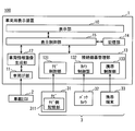
- FIG. 1 is a block diagram illustrating an example of a schematic configuration of a vehicle display system 100 according to the present embodiment.
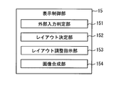
- FIG. 2 is a block diagram illustrating an example of a schematic configuration of the display control unit 15.
- FIG. 3 is an example of a vehicle information image 40A that adopts the first layout.
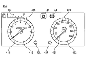
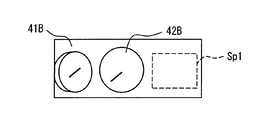
- FIG. 4 is an example of a vehicle information image 40B adopting the second layout.
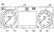
- FIG. 5 is an example of a vehicle information image 40C adopting the third layout.
- FIG. 6 is a flowchart for explaining the display mode switching process performed by the display control unit 15.
- FIG. 7 (C) are diagrams for explaining the operation and effect of this embodiment.
- FIG. 8 is a modification of the second layout.
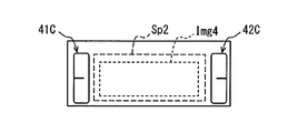
- FIG. 9 is an example in which one type of external image is displayed in the external image display area Sp2 included in the third layout.
- FIG. 10 is an example of a layout of a vehicle information image for displaying three types of external images.
- FIG. 11 is an example of a layout including two external image display areas.
- FIG. 1 is a diagram illustrating an example of a schematic configuration of a vehicle display system 100 according to the present embodiment.
- the vehicle display system 100 includes a navigation device 31, a back camera 32, and a mobile terminal 33 as examples of the vehicle display device 1, the in-vehicle ECU 2, and the external device 3 connected to the vehicle display device 1. It has.
- a vehicle in which the vehicle display system 100 is used is referred to as a host vehicle.
- the vehicle display device 1, the in-vehicle ECU 2, the navigation device 31, the back camera 32, and the mobile terminal 33 are connected to be able to communicate with each other.
- the communication method between the vehicular display device 1 and each device may be wireless communication or wired communication. Furthermore, the form which combined them may be sufficient.
- the vehicle display device 1 and the vehicle-mounted ECU 2, the navigation device 31, and the back camera 32 are connected by wire, and the mobile terminal 33 and the vehicle display device 1 are well known. It is assumed that the wireless connection is made using the short-range wireless communication technology.
- a wireless LAN standard such as IEEE802.11 or a short-range wireless communication standard such as Bluetooth (registered trademark) can be employed.
- the vehicular display device 1 and the mobile terminal 33 are configured to transmit and receive data by wireless communication.
- a configuration in which wired communication is performed may be employed.
- the vehicle display device 1 and the mobile terminal 33 may be configured to perform communication (so-called wide area communication) via a network such as the Internet or a telephone line network.
- the in-vehicle ECU 2 acquires information (referred to as vehicle information) relating to the state of the vehicle necessary for the driving operation from various sensors mounted on the own vehicle via the in-vehicle communication network built in the own vehicle.
- vehicle information includes, for example, the vehicle speed of the host vehicle, the engine rotation speed, the remaining amount of fuel, the engine coolant temperature, the total travel distance, the shift position, the direction indicator lever position, the door locking state, the seat This includes the belt wearing state and the headlight lighting state.
- information that notifies the driver of an abnormal state that has occurred in a drive system such as an engine also belongs to the vehicle information. Note that each piece of information belonging to the vehicle information as described above is referred to as element information.
- the in-vehicle ECU 2 sequentially outputs the above vehicle information to the vehicle display device 1 (for example, every 100 milliseconds).
- the host vehicle is a vehicle having an engine as a drive source, but may be a vehicle having a motor as a drive source, or a vehicle having both an engine and a motor as drive sources. May be.
- the rotational speed of the motor corresponds to the rotational speed of the engine described above.
- the navigation device 31 has the same function as a known navigation device, and for example, guides from the current position to the destination based on the map data stored in the navigation-side storage unit 311 and the current position of the host vehicle. A route guidance process for guiding the travel of the route is performed.
- the current position of the host vehicle may be detected sequentially (for example, every 100 milliseconds) using a known position detector (not shown).
- the map data is data including geographical information such as road data indicating a road connection relationship and map drawing data for displaying a map image.
- the navigation-side storage unit 311 may be a storage device (for example, a hard disk drive) made of a known storage medium.
- the navigation device 31 generates image data to be displayed on the display unit 10 included in the vehicular display device 1 in accordance with processing performed by the own device, and sequentially outputs the data to the vehicular display device 1. .
- the navigation device 31 when the destination is not set, the navigation device 31 generates image data (referred to as a surrounding map image) in which a mark indicating the position of the host vehicle is superimposed on a map image around the current location, and displays for the vehicle. Output to device 1.
- a destination setting image to be displayed on the screen for the user to set the destination is generated and output to the vehicle display device 1.
- an image showing the guidance route (referred to as a guidance map image) is further generated on the surrounding map image to display the vehicle display device 1.
- a navigation image an image generated by the navigation device 31 and displayed on the display unit 10 is referred to as a navigation image.
- the back camera 32 is a camera that captures a predetermined range behind the host vehicle.
- the back camera 32 may be installed, for example, near the upper part of the rear window or near the center of the rear bumper.
- the back camera 32 is an optical camera, and for example, a CMOS camera or a CCD camera can be used.
- the back camera 32 may be implement
- the back camera 32 captures images when the shift position is in the reverse position, and sequentially outputs the captured images (referred to as camera images) to the vehicle display device 1.
- the portable terminal 33 corresponds to a known smartphone or a portable terminal such as a tablet terminal.
- a general mobile terminal operates as the mobile terminal 33 in the present embodiment by executing an application program (hereinafter simply referred to as an application) for operating as the mobile terminal 33 included in the vehicle display system 100.
- the application only needs to be stored in, for example, a ROM included in the mobile terminal 33 while being executed by the CPU.
- the portable terminal 33 generates an image (referred to as a portable image) to be displayed on the display unit 10 included in the vehicular display device 1 and sequentially outputs data of the image to the vehicular display device 1.
- the portable image is generated according to the control state of the portable terminal 33. Note that the control state of the mobile terminal 33 transitions based on the user operation and the execution result of the program.
- the vehicle display device 1 includes a display unit 10, a vehicle interface unit (hereinafter referred to as a vehicle IF unit) 11, a connected device management unit 12, a vehicle information image generation unit 13, a storage unit 14, and a display control unit 15. Note that these units may be realized by hardware, software, or a combination thereof. Moreover, although the connection apparatus management part 12, the vehicle information image generation part 13, and the display control part 15 are each shown with the separated functional block, they may be implement
- the display unit 10 is a well-known display panel arranged in front of the driver's seat of the instrument panel of the host vehicle, and displays a display image input from the display control unit 15.
- the display unit 10 is capable of full-color display and can be configured using, for example, a TFT liquid crystal display, an organic EL display, or the like.
- the screen included in the display unit 10 has a substantially rectangular shape with long sides in the vehicle width direction.
- the vehicle IF unit 11 functions as an input / output interface for the vehicle display device 1 to communicate with the in-vehicle ECU 2.
- the vehicle IF unit 11 acquires vehicle information from the in-vehicle ECU 2 and sequentially outputs the vehicle information to the vehicle information image generation unit 13 and the display control unit 15.
- the connected device management unit 12 functions as an interface for communicating with the external device 3 connected to the vehicle display device 1 and manages the external device 3 connected to the vehicle display device 1. .
- the connected device management unit 12 performs processing for recognizing the external device 3 and establishes a communication connection.
- the connection device management unit 12 receives a wireless communication connection request from the external device 3, the connection device management unit 12 communicates with the external device 3 and establishes communication connection such as authentication processing.
- the connected device management unit 12 When the connected device management unit 12 acquires data of an image (referred to as an external image) output from the external device 3 that has established communication connection with the own device, the connected device management unit 12 displays the data of the external image. Sequentially output to the control unit 15.
- the navigation device 31, the back camera 32, and the mobile terminal 33 correspond to the external device 3
- the above-described navigation image, camera image, mobile image, and the like correspond to the external image.
- the connected device management unit 12 of the present embodiment has a navigation control unit 121, a camera control unit, as functions for controlling communication with the navigation device 31, the back camera 32, and the mobile terminal 33. 122 and a portable control unit 123. That is, the navigation control unit 121 controls communication with the navigation device 31 and, when navigation image data is input from the navigation device 31, sequentially outputs the navigation image data to the display control unit 15.
- the camera control unit 122 controls communication with the back camera 32 and, when camera image data is input from the back camera 32, sequentially outputs the camera image data to the display control unit 15.
- the portable control unit 123 controls communication with the portable terminal 33 and, when portable image data is input from the portable terminal 33, sequentially outputs the portable image data to the display control unit 15.
- the navigation image, camera image, and mobile image data all include information (pixel information) indicating the color of each pixel constituting the image. Further, when outputting the external image to the display control unit 15, the connected device management unit 12 outputs information indicating the external device 3 that is the output source of the external image together with the external image to the display control unit 15. To do.
- the display control unit 15 can specify the external device 3 that is the output source of the external image. Further, even when external images from a plurality of external devices 3 are input, the display control unit 15 separates the plurality of types of external images for each external device 3 from which the external images are output. It can be handled separately.
- the external device 3 generates an external image
- the connected device management unit 12 acquires the data of the external image from the external device 3, but the configuration is not limited thereto.
- the external device 3 may output data for rendering an external image (drawing data), and the connected device management unit 12 may generate an external image based on the rendering data.
- the drawing data includes graphic and text data to be included in the external image, their layout, and data specifying the color of each area.
- the drawing data may represent the difference between the external image currently displayed and the external image to be newly generated.
- the connected device management unit 12 corresponds to an external image acquisition unit described in the claims.
- the vehicle information image generation unit 13 draws a vehicle information image (including text display) 40 showing various element information belonging to the vehicle information based on the vehicle information input from the vehicle IF unit 11 and displays the data. Sequentially output to the control unit 15. More specifically, the vehicle information image generating unit 13 includes images (elements) corresponding to each of the element information belonging to the vehicle information, the type specified by the display control unit 15 or the element information of a predetermined type. Draw an information image).
- the vehicle information image 40 is produced
- the vehicle information image generation unit 13 generates a vehicle information image 40 having a shape corresponding to the shape of the screen included in the display unit 10 (that is, a substantially rectangular shape).
- the long side direction of the display screen of the display unit 10 is referred to as the horizontal direction of the screen, and the short side direction of the screen is referred to as the vertical direction of the screen.
- the vehicle information image generation unit 13 of the present embodiment includes three different layouts of first, second, and third layouts as display modes (hereinafter, layouts) of various element information images in the vehicle information image 40, and displays them. Each layout is switched and adopted based on an instruction from the control unit 15.
- the first layout is a layout that is employed when only the vehicle information is displayed on the display unit 10 without displaying an external image input from the external device 3. Therefore, the first layout does not include an area for displaying an external image (external image display area).
- the second layout is a layout including an external image display area having a size capable of displaying one external image.
- the third layout is a layout including an external image display area having a size capable of displaying two external images. The size of one external image may be designed as appropriate.
- each element information image with which the vehicle information image 40 is provided is drawn with the display mode according to the layout employ
- FIG. 1 A specific example of the vehicle information image 40 adopting each of these layouts and its effect will be described later.
- each element information image with which the vehicle information image 40 is provided is drawn with the display mode according to the layout employ
- the first layout corresponds to the basic arrangement mode described in the claims
- the second layout and the third layout correspond to the modified arrangement mode described in the claims.
- the second layout corresponds to the first modified arrangement mode described in the claims
- the third layout corresponds to the second modified arrangement mode described in the claims.
- the vehicle information image generation unit 13 changes the arrangement and display mode of the element information image from the currently employed layout to the indicated layout. To do.
- the vehicle information image generation unit 13 of the present embodiment is configured to sequentially output the vehicle information image 40 representing the process of transition from the current layout to the new layout to the display control unit 15.
- the image in the process of shifting the layout represents the process of movement, rotation, and deformation of the element information image in the vehicle information image 40.
- the transition from one layout to another may be a mode in which the process is not displayed and the transition is instantaneous.
- the storage unit 14 operates as a buffer that temporarily stores the vehicle information image 40 generated by the vehicle information image generation unit 13 and the external image acquired by the connected device management unit 12. Further, the storage unit 14 stores an image to be displayed when the vehicle display device 1 is activated, a background image of the vehicle information image 40, and the like.
- the storage unit 14 may be realized by a known storage medium such as a RAM or a flash memory.
- the display control unit 15 is configured as a normal computer, and includes a well-known CPU, a non-volatile memory such as a ROM and a flash memory, a volatile memory such as a RAM, an I / O, and a bus line (which connects these configurations). All are not shown).
- the nonvolatile memory stores programs and data for executing various processes. And various functions are implement
- the display control unit 15 includes an external input determination unit 151, a layout determination unit 152, a layout adjustment instruction unit 153, and an image composition unit 154 as functional blocks as shown in FIG.
- the external input determination unit 151 plays a role as an interface with the connected device management unit 12 in the display control unit 15. More specifically, it is determined whether or not external image data is input from the connected device management unit 12.
- the external device 3 that has output the external image is acquired from the connected device management unit 12 and the external image currently input from the connected device management unit 12 is acquired. Identifies whether it is a navigation image, a camera image or a portable image. That is, when external image data is input, the external input determination unit 151 identifies the external device 3 that is the output source of the external image data.
- the external input determination unit 151 determines whether or not input of the external image from the external device 3 to the connected device management unit 12 is stopped. Inquire. When the response indicating that the input of the external image from the external device 3 is stopped is obtained from the connected device management unit 12, it is determined that the output of the external image by the external device 3 is stopped.
- the layout determination unit 152 determines the layout of the vehicle information image 40 according to the number of external devices 3 that are outputting external images. More specifically, when there is no external device 3 outputting an external image, the layout of the vehicle information image 40 is determined as the first layout. When the number of external devices 3 outputting an external image is one, the layout of the vehicle information image 40 is determined as the second layout. Furthermore, when the number of external devices 3 outputting external images is two, the layout of the vehicle information image 40 is determined as the third layout.
- the arrangement of the two external images in the external image display area is determined according to the combination of the external devices 3 that output the external images.
- the arrangement of the external image in the external image display area may be set in advance so as to be uniquely determined according to the combination of the external devices 3 outputting the external image.
- the data indicating the correspondence relationship as to whether to adopt any one of the first, second, and third layouts with respect to the number of external devices 3 outputting external images is displayed by the display control unit 15. What is necessary is just to store in storage areas, such as ROM provided, and the memory
- two high-priority devices are selected as appropriate based on preset priorities.
- the priority for each external device 3 may be set higher in descending order of the expected value that contributes to safe driving.
- the priority of the camera image is set to the highest
- the priority of the navigation image is set to the next highest
- the priority of the portable image is set to the lowest.
- the type of external image selected here is combined with the vehicle information image 40 by an image combining unit 154 described later and displayed on the display unit 10.
- the layout of the vehicle information image 40 is assumed to have a configuration that does not include a layout that displays three or more external images, there are three or more external devices 3 that output external images.
- the present invention is not limited to this.
- the display unit 10 when the vehicle information image 40 can be displayed in a layout having the same number of external image display areas as the number of external devices 3 outputting external images, the display unit 10 as in the present embodiment. There is no need to select the type of image to be displayed on the screen.
- the layout adjustment instruction unit 153 instructs the vehicle information image generation unit 13 to draw the vehicle information image 40 with the layout determined by the layout determination unit 152.
- the image composition unit 154 Based on the vehicle information image 40 input from the vehicle information image generation unit 13 and the background image stored in the storage unit 14, the image composition unit 154 displays an image (display image and display image) to be displayed on the screen of the display unit 10. Generate). When at least one type of external image is input from the connected device management unit 12, a display image is generated based on the external image in addition to the vehicle information image 40 and the background image.
- a display image in which the vehicle information image 40 is superimposed so as to exist on the front side (driver side) of the screen from the background image is generated.
- a display image in which the external image is arranged in the external image display area of the vehicle information image 40 is generated.
- the external image is arranged between the background image and the vehicle information image 40, and the vehicle information image 40 is arranged and displayed on the forefront.
- each external image is arranged in the external image display area based on the arrangement of the external images determined by the layout determining unit 152 with respect to the external image display area. Generate a display image. Also in this case, as an example, the image is synthesized so that the vehicle information image 40 is displayed in the foreground.
- the display image data generated by the image composition unit 154 as described above is sequentially output to the display unit 10. Then, the display unit 10 provides the driver with various information by sequentially displaying the display images generated by the image composition unit 154.
- the sign of the vehicle information image when the first layout is adopted is 40A
- the sign of the vehicle information image when the second layout is adopted is 40B
- the third layout is adopted
- the sign of the vehicle information image is 40C.
- each layout is not distinguished, it is described as a vehicle information image 40.
- the vehicle information image 40 corresponds to element information such as the engine speed, the vehicle speed, the lighting state of the direction indicator, the presence or absence of abnormality of the host vehicle, the shift position, and the remaining fuel amount.
- An element information image is included. As described above, each element information image is drawn in a display mode corresponding to the layout adopted in the vehicle information image 40.
- FIG. 3 is an example of a vehicle information image 40A when the first layout is adopted.
- the vehicle information image 40A includes a rotation speed meter 41A, a vehicle speed meter 42A, direction indication icons 43L and 43R, a warning icon 44, a shift position icon 45, and a remaining fuel image 46 as element information images. .
- Rotational speed meter 41A is an image representing the current rotational speed of the engine.
- the rotational speed meter 41A rotates the pointer 411 according to the rotational speed detected by the rotational speed sensor on a substantially circular scale plate 412 having a scale and a numerical value on the circumference, so that the current engine A display mode imitating a so-called analog meter that indicates the rotation speed is used.
- the rotational speed meter 41A is generated based on a substantially cylindrical three-dimensional model (which is referred to as a rotational speed meter model) whose top surface is the scale plate 412 and whose height is smaller than the radius of the top surface. It is an image. That is, the rotation speed meter 41A is an image of the rotation speed meter model dial plate 412 as viewed from the front. The image of the dial 412 as seen from the front is that the rotational speed meter 41A is viewed from a point on a straight line in which the central axis of the rotational speed meter model is extended to the scale 412 side. Points to the image.
- the central axis of the rotational speed meter model here is a central axis when the rotational speed meter model is regarded as a cylinder, and indicates a line segment connecting the center of the bottom surface to the center of the top surface corresponding to the dial 412. It is.
- the scale for showing a rotational speed shall be provided to the side part of the rotational speed meter model along the circumferential direction.
- the circumferential direction refers to the direction of rotation of the side surface when the center axis is rotated as the rotation axis.
- This rotational speed meter model corresponds to the first three-dimensional model recited in the claims.
- symbol of the rotational speed meter in a 1st layout is set to 41A
- symbol of the rotational speed meter in the 2nd and 3rd layout mentioned later is set to 41B and 41C, respectively.
- the rotation speed meter 41 is described. Information on the rotational speed of the engine corresponds to the first element information recited in the claims, and the rotation speed meter 41 corresponds to an example of the first element information image recited in the claims.
- the vehicle speed meter 42A is an image representing the current vehicle speed. Similarly to the rotational speed meter 41A, the vehicle speed meter 42A also has a display mode that imitates an analog meter that represents the current vehicle speed by rotating the pointer 421 on the scale plate 422 in accordance with the detection value of the vehicle speed sensor. Further, the vehicle speed meter 42B is also an image generated based on a substantially cylindrical three-dimensional model (this is a vehicle speed meter model) having the scale plate 422 as an upper surface and a height smaller than the radius of the upper surface. This is an image of the scale plate 422 of this vehicle speed meter model viewed from the front. It is assumed that a scale for representing the vehicle speed is provided along the circumferential direction on the side surface portion of the vehicle speed meter model. This vehicle speed meter model corresponds to the second three-dimensional model recited in the claims.
- symbol of the vehicle speed meter in a 1st layout is set to 42A
- symbol of the vehicle speed meter in the 2nd and 3rd layout mentioned later is set to 42B and 42C, respectively.
- the vehicle speed meter 42 when not distinguishing the difference in the display mode based on these layout differences, it describes as the vehicle speed meter 42.
- the vehicle speed information corresponds to the second element information described in the claims
- the vehicle speed meter 42 corresponds to the second element information image described in the claims.
- the direction indication icons 43L and 43R are icon images (hereinafter referred to as icons) indicating the lighting state of the direction indication lamps.
- the display modes of the direction indicating icons 43L and 43R are switched based on the output signal of the direction indicating lever position sensor that detects the position of the direction indicating lever or the output signal of the hazard switch. For example, when the direction indicator lamp is not lit, the direction indication icons 43L and 43R are displayed inconspicuously by being the same color as the background color or colorless and transparent. On the other hand, when the direction indicator lamp is lit, the direction indicator icon 43L (or 43R) corresponding to the lit direction indicator lamp is highlighted. As a mode of highlighting, for example, the direction indication icon on the side corresponding to the lit direction indication lamp may be displayed while blinking in green with high luminance.
- the warning icon 44 is an icon for notifying the driver of an abnormality of the host vehicle, and is displayed based on information input from the in-vehicle ECU 2 that an abnormality has occurred in a drive system such as an engine or a body system. It only has to be done.
- the warning icon 44 may display different images depending on the type of information to be notified to the driver, such as, for example, seat belt not attached, door unlock, half door, oil abnormality, and the like.
- the warning icon 44 may be an image based on a warm color such as red or orange so that the driver's eyes are more visible than other images.
- the shift position icon 45 is an icon representing the current shift position, and the display is switched based on the shift position detected by the shift position sensor.
- the remaining fuel image 46 is an image representing the remaining amount of fuel.
- positioned in the vehicle information image 40 is made into a colorless and transparent area
- the display can be displayed transparently.
- the rotational speed meter 41A and the vehicle speed meter 42A are arranged in parallel with a predetermined interval in the horizontal direction of the screen.
- the area sandwiched between the rotational speed meter 41 and the vehicle speed meter 42 is not large enough to display an external image.
- the vehicle information image 40A having the first layout does not include an external image display area.
- the rotation speed meter 41A and the vehicle speed meter 42A can be displayed in a larger size so that the visibility of each element information image can be further enhanced.
- another element information image is not arranged between the rotation speed meter 41A and the vehicle speed meter 42A.
- the present invention is not limited to this.
- a shift position icon 45, a warning icon 44, a water temperature display image showing the temperature of engine cooling water, and the like may be arranged between the rotation speed meter 41 and the vehicle speed meter.
- FIG. 10 an example of the vehicle information image 40B when the second layout is adopted is shown in FIG.
- the rotational speed meter 41B and the vehicle speed meter 42B are arranged apart from each other in the horizontal direction of the screen as compared with the first layout, and one external image Img1 is interposed therebetween.
- An external image display area Sp1 of a size that can be displayed is provided.
- the rotational speed meter 41B and the vehicle speed meter 42B are arranged apart from each other in the horizontal direction of the screen so that the external image display area Sp1 is formed.
- the external image display area Sp1 is an area for arranging an external image in the display control unit 15 to be described later.
- the vehicle information image generating unit 13 no element information image is arranged in the area.
- the external image display area Sp1 may be formed using empty areas generated by moving or deforming various element information images (for example, the vehicle speed meter 42), or a combination thereof.
- the deformation here refers to rotation, enlargement, reduction, and the like.
- the rotation speed meter 41B is not only moved to the horizontal end of the screen in order to secure the external image display area Sp1, but also an image obtained by slightly viewing the rotation speed meter model that is the source of the rotation speed meter 41B. By doing so, the area occupied by the dial 412 on the screen is reduced. More specifically, the rotation speed meter 41 ⁇ / b> A of the first layout is centered on the screen center of the screen horizontal direction ends of the scale plate 412 with a straight line passing through the center of the scale plate 412 parallel to the screen vertical direction as the rotation axis. It is assumed that the image is rotated by a certain angle (for example, 9 degrees) so that the end on the side becomes the back side of the screen.
- the rotation angle here may be appropriately designed within a range in which the visibility of the value indicated by the scale of the scale plate 412 and the pointer 411 is ensured, for example, taking a value between 5 degrees and 10 degrees. To do.
- the vehicle speed meter 42B of the second layout also uses the vehicle speed meter 42A of the first layout as an end portion in the horizontal direction of the screen of the scale plate 422, with a straight line passing through the center of the scale plate 422 being parallel to the vertical direction of the screen. Among these, the image is rotated by a certain angle so that the end on the center side of the screen is on the back side of the screen.
- the vehicle speed meter 42B of the second layout is an image obtained by viewing the vehicle speed meter model from a direction that makes a certain angle with respect to the central axis direction.
- the scale plates 412 and 422 are displayed from an oblique direction.
- size which the scale boards 412 and 422 occupy on a screen can be made small, and external image display area Sp1 can be ensured. Further, since the visual change amount from the rotation speed meter 41A and the vehicle speed meter 42 in the first layout is small, it is possible to suppress a sense of discomfort given to the driver.
- a part indicated by 413 represents a part of the side surface of the substantially cylindrical rotational speed meter 41
- a part indicated by 423 represents a part of the side face of the substantially cylindrical vehicle speed meter 42.
- scales and numbers are provided in the circumferential direction on the side surface 413 and the side surface 423, but the scales and numbers are omitted in FIG. 4 for simplification.
- FIG. 5 is an example of the vehicle information image 40C when the third layout is adopted.
- an external image display area Sp2 larger than the external image display area Sp1 provided in the second layout is converted into a rotation speed meter 41C and a vehicle speed meter 42C.
- the external image display area Sp2 has a size capable of displaying two external images Img1 and Img2.
- the rotation speed meter 41C, the external image Img1, the external image Img2, and the vehicle speed meter 42C are arranged in the horizontal direction of the screen in this order on the screen of the display unit 10. Displayed side by side.
- the rotation speed meter 41C of the third layout further rotates from the state displayed in the second layout about a straight line parallel to the vertical direction of the screen passing through the center of the scale plate 412 as a rotation axis, and the side surface 413 of the rotation speed meter 41 Is an image displayed so as to face the screen. That is, the rotation speed meter 41 is rotated 90 degrees about a straight line passing through the center of the dial 412 and parallel to the screen vertical direction from the state where the rotation speed meter model is displayed in the first layout.
- a scale and a numerical value for representing the rotational speed of the engine are given to the side surface 413 of the rotational speed meter model.
- the rotational speed meter 41C of the third layout represents the current rotational speed of the engine by rotating and displaying the rotational speed meter model in the direction of arrow A41 in the figure with respect to the fixed pointer 414.
- the scale of the rotational speed meter model moves in the direction of the arrow A41 in the figure by rotating the central axis of the rotational speed meter model in the vertical direction of the screen as the axis of rotation, and the value indicated by the pointer 414 Can be changed.
- the area displaying the side surface 413 corresponds to the scale display section described in the claims.
- the vehicle speed meter 42C in the third layout further rotates from the state displayed in the second layout around a straight line parallel to the vertical direction of the screen passing through the center of the scale plate 422, and the side surface of the vehicle speed meter 42 is It is an image displayed so as to face the screen. That is, from the state where the vehicle speed meter model is displayed in the first layout, the rotation speed meter 41 is rotated 90 degrees about a straight line passing through the center of the dial 412 and parallel to the vertical direction of the screen.
- a scale for expressing the vehicle speed is also provided on the side surface of the vehicle speed meter model, and the vehicle speed meter 42C displays an image obtained by rotating the vehicle speed meter model in the direction of arrow A42 in the figure with respect to the fixed pointer 414. By doing so, it represents the current vehicle speed. Therefore, the area displaying the side surface 423 also corresponds to the scale display portion described in the claims.
- the rotational speed meter model has a substantially cylindrical shape whose height is smaller than the radius, and the rotational speed meter model has a height required to display a scale (including numbers). Can do. Therefore, an image representing the rotational speed meter model is displayed when the side surface 413 is mainly displayed on the display unit 10 rather than when the scale plate 412 corresponding to the upper surface of the rotational speed meter model is mainly displayed on the display unit 10. Occupies a small area on the display screen. Therefore, by displaying the rotation speed meter 41C as in the third layout, the area occupied by the image on the display screen can be made smaller than the rotation speed meter 41B in the second layout.
- the effect of area saving by the display mode of the rotational speed meter 41C has been described, but the same applies to the vehicle speed meter 42C. That is, by displaying the vehicle speed meter 42C as in the third layout, the area occupied by the vehicle speed meter 42C on the screen can be reduced. Then, by reducing the display area of each meter image, a second external image display area can be secured. For convenience, the remaining fuel image 46 is also translated from the center of the screen in accordance with the change (deformation and movement) of the display mode of the rotation speed meter 41C.
- the rotational speed meter 41C displayed in the third layout represents the rotational speed meter model that is the basis of the rotational speed meters 41A and 41B displayed in the first layout and the second layout from different angles. Is. That is, the rotation speed meter 41C displayed in the third layout is an image representing the same model as the rotation speed meters 41A and 41B in the first layout and the second layout.
- the rotational speed meter 41B in the second layout includes a part of the side surface of the rotational speed meter model mainly displayed on the rotational speed meter 41 in the third layout.
- the rotation speed meter 41B in the second layout and the rotation speed meter 41C in the third layout are images that include a common part in the rotation speed meter model.
- the rotational speed meter 41C displayed in the third layout corresponds to the rotational speed meter 41B displayed in the second layout.
- the correspondence of the rotational speed meters 41 between different layouts is as follows: It becomes easier.
- the rotation speed meter model is moved to the horizontal end of the screen while rotating so that the side faces the front of the screen. Display the process.
- the effect of the display mode of the rotational speed meter 41C has been described, but the same applies to the vehicle speed meter 42C. That is, by displaying the vehicle speed meter 42 as in the present embodiment, the vehicle speed meter 42C displayed in the third layout corresponds to the vehicle speed meter 42B displayed in the second layout. Can be recognized easily.
- a process in which the display control unit 15 switches the display mode of the display image (referred to as a display mode switching process) will be described using the flowchart shown in FIG.
- the flowchart shown in FIG. 6 is assumed to be performed sequentially (for example, every 20 milliseconds).
- step S1 the external input determination unit 151 determines whether or not an interrupt has occurred.
- the interruption here means that the external device 3 that has not output the image data until the previous time has started to output the data of the external image to the vehicle display device 1. That is, it is determined that an interrupt has occurred when external image data of the external device 3 that has not output image data until the previous time starts to be input from the connected device management unit 12. If an interrupt occurs, step S1 becomes YES and the process moves to step S2. On the other hand, if no interrupt has occurred, step S1 is NO and the process proceeds to step S6.
- step S2 the external input determination unit 151 identifies the external device 3 that has started to output an external image based on the data input from the connected device management unit 12, and proceeds to step S3.
- step S3 the external input determination unit 151 receives the result of step S2 or step S6 described later, specifies the number of external devices 3 that are currently outputting external images, and proceeds to step S4. If there are a plurality of external devices 3 outputting external images, the combination is specified in step S3.
- step S4 the layout determining unit 152 determines the layout of the vehicle information image 40 according to the number of external devices 3 specified in step S3.
- the layout to be newly set is determined to be the third layout
- the arrangement of the external image in the external image display area Sp2 included in the vehicle information image 40C having the third layout is determined. For example, when a navigation image and a portable image are input, the navigation image is arranged at the position of the external image Img1 located on the left side of the external image display area Sp2, and the portable image is arranged at the position of the external image Img2 located on the right side. To do.
- the display unit 10 When there are three or more external devices 3 that output an external image, the display unit 10 is based on the priority set in advance for the type of the external device 3 (that is, the external image). The process of selecting two types of external images to be displayed on the screen is also performed in step S4. When the above process is completed, the process proceeds to step S5.
- step S5 the layout adjustment instructing unit 153 instructs the vehicle information image generating unit 13 to shift from the currently adopted layout to the layout determined in step S4, and newly displays the display mode of the current display image.
- a display mode shift process a different display mode
- the image composition unit 154 causes the vehicle information image 40 input from the vehicle information image generation unit 13 to be sequentially reflected on the display image and displayed on the display unit 10. That is, a process of shifting the layout of the vehicle information image 40 is displayed.
- the external image for example, when a new external image is additionally displayed, the external image is displayed at the timing when the transition of the layout of the vehicle information image 40 is completed.
- the external image to be deleted is deleted at the same time as the display mode transition process is started.
- a known visual effect such as gradually reducing the size of the external image to make it invisible or fading out may be employed.
- it may be displayed stepwise using a known visual effect (fade in or the like).
- step S6 the external input determination unit 151 determines whether there is an external device 3 that has output an external image until the previous time, for which output of the image has been stopped. If there is an external device 3 for which image output has been stopped, step S6 is YES and the process proceeds to step S3. On the other hand, if there is no external device 3 that has stopped outputting images, step S6 is NO and this flow ends.
- FIGS. 7A to 7C show how the display mode changes in multiple stages depending on the number of external devices 3 outputting image data to the vehicle display device 1.
- a vehicle information image 40A adopting the first layout is displayed on the display unit 10 as shown in FIG. Thereafter, when an external image starts to be input from one external device 3 (step S1, YES), the vehicle information image 40 shifts to the second layout as shown in FIG. 7B and displays the external image. . When an external image starts to be input from another external device 3 (step S1, YES), the vehicle information image 40 shifts from the second layout to the third layout as shown in FIG. Display two external images.
- the layout of the vehicle information image 40 is changed to the third layout. To shift to the second layout.
- the layout of the vehicle information image 40 is Transition from the second layout to the first layout is performed.
- the vehicle information image generation unit 13 when no external image is input, the vehicle information image generation unit 13 generates a vehicle information image 40A that does not include an external image display area, and the image composition unit 154 includes the vehicle information image 40A. An image obtained by combining the background images is displayed on the display unit 10.
- vehicle information images 40B and 40C having external image display areas corresponding to the number of the external images are generated, and the image composition unit 154 includes external images provided in the vehicle information images. An image in which an external image is arranged in the image display area is displayed on the display unit.
- the external image display areas Sp1 and Sp2 are areas for displaying an external image, and are areas adjusted so that an image indicating vehicle information is not arranged. Therefore, even if an external image is arranged in the external image display area, a part of the vehicle information image 40 is not made visible by the external image, and conversely, a part of the external image is not made visible by the vehicle information image 40. That is, according to the above configuration, both an external image corresponding to the external device 3 and an image showing vehicle information can be displayed simultaneously.
- the layout of the vehicle information image 40 can be changed stepwise from the first layout to the second layout and from the second layout to the third layout.
- the external image display area Sp1 is provided between the rotation speed meter 41B and the vehicle speed meter 42B, but the present invention is not limited thereto.
- the vehicle speed meter 42B is disposed at the center in the horizontal direction of the screen, and the vehicle speed meter 42B and the rotational speed meter 41B are disposed adjacent to each other.
- the vehicle information image generation unit 13 includes a first layout, a second layout, and a third layout.
- the third layout is a configuration that is used when displaying two external images. However, it is not limited to this.
- one external image Img4 may be displayed in the external image display area Sp2 provided in the third layout. Whether one external image is displayed in a size corresponding to a predetermined external image or whether it is displayed in a size corresponding to a predetermined external image as shown in FIG. It may be determined according to. For example, an image used for safety confirmation such as a camera image may be set to be displayed in a relatively large size as shown in FIG.
- the layout of the vehicle information image 40 may be determined in accordance with the type of external image input to the vehicle display device 1. That is, for a type of external image to be displayed in a larger size, a layout having a relatively large external image display area may be adopted.
- the number of layouts provided in the vehicle information image generation unit 13 is not limited to three.
- a fourth layout may be provided in which an external image display area Sp3 having a size capable of displaying up to three external images of a predetermined size is provided.
- two external images having different sizes may be arranged and displayed in one external image display area Sp3.
- the display size of the external image in the external image display area may be changed according to the size and type of the input external image.
- the layout of the vehicle information image 40 and the display size of each external image may be determined by the number or type of input external images or a combination thereof.
- the input external images are a mobile image and a navigation image
- the third layout is adopted, and the images are displayed side by side in the external image display area Sp2 with the same display size.
- the fourth layout shown in FIG. 10 is adopted, and the navigation image is sized in the external image display area Sp3 in a size corresponding to one external image defined in advance.
- the camera image may be displayed in the size of two external images. More specifically, the navigation image may be arranged at the position of the external image Img1, and the camera image may be displayed in a region where the external images Img2 and Img3 are combined.
- FIG. 5 the configuration shown in FIG. 5 is exemplified as the third layout in the case of displaying two external images, but the present invention is not limited to this.
- the layout in the case of displaying two external images may be configured to include two separate external image display areas Sp4 and Sp5 as shown in FIG. 11, for example.
- FIG. 11 shows an arrangement form in which the rotation speed meter 41C and the vehicle speed meter 42C are adjacent to each other at the center in the horizontal direction of the screen, and the external image display areas Sp4 and Sp5 are arranged one by one on both sides thereof.
- the vehicle speed and the engine rotation speed are adopted as the two types of element information that occupy most of the screen in the first layout, and these are displayed in an analog meter format.
- the present invention is not limited to this.
- an image showing the remaining fuel amount may be displayed in an analog meter format.
- the display mode of the element information image displayed in the analog meter format may be changed to the digital meter format in order to secure more external image display areas.
- the digital meter format indicates that the state or value of the element information is represented by a character string without using a pointer and a scale board.
- the rotation speed meter 41 displayed in each of the first, second, and third layouts is the same when the same three-dimensional model (that is, the rotation meter model) is viewed from different angles.
- the vehicle speed meter 42 may have a display mode imitating an analog meter in the first layout, and a digital meter type display mode in the second and third layouts.
- each section is expressed as, for example, S1. Further, each section can be divided into a plurality of subsections, while a plurality of sections can be combined into one section. Further, each section configured in this manner can be referred to as a device, module, or means.
Landscapes
- Engineering & Computer Science (AREA)
- Physics & Mathematics (AREA)
- General Physics & Mathematics (AREA)
- Computer Hardware Design (AREA)
- Theoretical Computer Science (AREA)
- Chemical & Material Sciences (AREA)
- Combustion & Propulsion (AREA)
- Transportation (AREA)
- Mechanical Engineering (AREA)
- Instrument Panels (AREA)
- Indicating Measured Values (AREA)
- Controls And Circuits For Display Device (AREA)
Abstract
This vehicle display system is provided with: a display unit (10); a display control unit (15) for controlling a display image displayed on the display unit; a vehicle information image-generating unit (12) for generating a vehicle information image indicating vehicle information; and an external image acquisition unit (12) for acquiring external images indicating information corresponding to external devices. The vehicle information image-generating unit generates, in accordance with the number of the external images and/or the kinds thereof, the vehicle information image under a display mode in which an external image-displaying area for displaying the external images is provided. The display control unit displays, on the display unit, a display image in which the external images are arranged within the external image-displaying area.
Description
本出願は、2014年6月13日に出願された日本出願番号2014-122553号に基づくもので、ここにその記載内容を援用する。
This application is based on Japanese Application No. 2014-122553 filed on June 13, 2014, the contents of which are incorporated herein by reference.
本開示は、車両用表示装置、特にメータ画像を表示する車両用表示装置に関するものである。
The present disclosure relates to a vehicle display device, and more particularly to a vehicle display device that displays a meter image.
従来、車速、エンジン回転速度、燃料残量および積算走行距離などの車両情報を、自車両のインストゥルメントパネルの運転席正面に配置されたメータディスプレイに表示する車両用表示装置がある。
Conventionally, there is a vehicle display device that displays vehicle information such as a vehicle speed, an engine rotation speed, a remaining amount of fuel, and an accumulated travel distance on a meter display arranged in front of a driver's seat of an instrument panel of the host vehicle.
例えば特許文献1には、メータディスプレイに表示する車両情報の種類を、車両の状態に応じて変更するとともに、その表示態様を切り替える車両用表示装置が開示されている。この車両用表示装置は、通常の走行時においては車両速度を示す第1画像と、エンジン回転速度を示す第2画像を表示する。そして、車両速度やエンジン回転速度以外に、例えば燃料残量の低下等の、ドライバに報知すべき情報が生じた場合には、当該報知すべき情報を示す第3画像を第1画像と第2画像の間に配置した表示態様へと、表示画面の表示態様を変更する。
For example, Patent Document 1 discloses a vehicle display device that changes the type of vehicle information displayed on a meter display in accordance with the state of the vehicle and switches the display mode. This vehicle display device displays a first image indicating the vehicle speed and a second image indicating the engine speed during normal driving. In addition to the vehicle speed and the engine rotation speed, when information to be notified to the driver, such as a decrease in the remaining fuel amount, is generated, a third image indicating the information to be notified is displayed as the first image and the second image. The display mode of the display screen is changed to the display mode arranged between the images.
特許文献1に開示の車両用表示装置は、車速やエンジン回転速度、燃料残量などの、車両情報に属する種々の情報を、その表示する情報の種類や組み合わせに応じて異なる表示態様で表示するものである。
The vehicle display device disclosed in Patent Literature 1 displays various information belonging to the vehicle information such as the vehicle speed, the engine rotation speed, and the fuel remaining amount in different display modes depending on the type and combination of the information to be displayed. Is.
ところで、今後は車両用表示装置と種々の外部機器とを連携させ、その外部機器から入力された画像、又は、外部機器から入力されたデータに基づいて車両用表示装置が生成した画像を、車両情報を示す画像とともに1つの表示画面に表示させたいという需要がある。なお、以降では外部機器から入力された画像、又は、外部機器から入力されたデータに基づいて自装置が生成した画像を、外部画像と称する。
By the way, in the future, the vehicle display device and various external devices will be linked, and an image input from the external device or an image generated by the vehicle display device based on data input from the external device will be There is a demand for displaying an image showing information on one display screen. Hereinafter, an image input from an external device or an image generated by the own apparatus based on data input from the external device is referred to as an external image.
そのような車両情報を示す画像と外部画像とを同時に表示する構成においては、車両情報を示す画像と外部画像のそれぞれに対して、視認性を確保する必要がある。また、常に外部画像が車両用表示装置に入力されているとは限らないため、外部画像の有無に応じて、表示画面の表示態様を調整する必要がある。
In such a configuration in which an image showing vehicle information and an external image are displayed simultaneously, it is necessary to ensure visibility for each of the image showing vehicle information and the external image. Moreover, since the external image is not always input to the vehicle display device, it is necessary to adjust the display mode of the display screen according to the presence or absence of the external image.
しかしながら、特許文献1の車両用表示装置では、外部機器から入力された画像を表示するようなシステム構成は想定されていないため、当然ながら、外部画像を表示する場合の車両情報を示す画像の表示態様については検討されていない。
However, since the system configuration for displaying an image input from an external device is not assumed in the vehicle display device of Patent Document 1, it is a matter of course that an image is displayed indicating vehicle information when displaying an external image. The aspect has not been studied.
本開示は、外部機器に対応する外部画像と、車両情報を示す画像の両方を表示できる車両用表示装置を提供することを目的とする。
This disclosure is intended to provide a vehicle display device that can display both an external image corresponding to an external device and an image indicating vehicle information.
本開示の第一の態様において、車両用表示装置は、表示画像を表示する表示部と、前記表示部に表示する表示画像を制御する表示制御部と、車両情報を示す車両情報画像を生成する車両情報画像生成部と、当該車両用表示装置と接続する外部機器に対応する情報を示す外部画像を取得する外部画像取得部と、を備える。前記車両情報画像生成部は、前記外部画像取得部が取得している前記外部画像の数、および種類の少なくとも一方に応じて、外部画像取得部が取得している前記外部画像を表示するための外部画像表示領域を設けた表示態様で前記車両情報画像を生成する。前記表示制御部は、前記車両情報画像に設けられている前記外部画像表示領域に、前記外部画像取得部が取得した前記外部画像を配置した表示画像を前記表示部に表示する。
In the first aspect of the present disclosure, the vehicle display device generates a display unit that displays a display image, a display control unit that controls a display image displayed on the display unit, and a vehicle information image that indicates vehicle information. A vehicle information image generation unit; and an external image acquisition unit that acquires an external image indicating information corresponding to an external device connected to the vehicle display device. The vehicle information image generation unit displays the external image acquired by the external image acquisition unit according to at least one of the number and type of the external images acquired by the external image acquisition unit. The vehicle information image is generated in a display mode provided with an external image display area. The display control unit displays on the display unit a display image in which the external image acquired by the external image acquisition unit is arranged in the external image display region provided in the vehicle information image.
ここで、外部画像表示領域は外部画像を表示するための領域であるため、車両情報を示す画像は配置されないように調整される領域である。したがって、外部画像表示領域に外部画像を配置しても、外部画像によって車両情報画像の一部が見えなくなったり、逆に、車両情報画像によって外部画像の一部が見えなくなったりはしない。すなわち、以上の構成によれば、外部機器に対応する外部画像と車両情報を示す画像の両方を同時に表示することができる。
Here, since the external image display area is an area for displaying an external image, the image indicating the vehicle information is an area adjusted so as not to be arranged. Therefore, even if an external image is arranged in the external image display area, a part of the vehicle information image cannot be seen by the external image, and conversely, a part of the external image cannot be seen by the vehicle information image. That is, according to the above configuration, both an external image corresponding to an external device and an image showing vehicle information can be displayed simultaneously.
本開示についての上記目的およびその他の目的、特徴や利点は、添付の図面を参照しながら下記の詳細な記述により、より明確になる。その図面は、
図1は、本実施形態に係る車両用表示システム100の概略的な構成の一例を示すブロック図であり、
図2は、表示制御部15の概略的な構成の一例を示すブロック図であり、
図3は、第1レイアウトを採用している車両情報画像40Aの一例であり、
図4は、第2レイアウトを採用している車両情報画像40Bの一例であり、
図5は、第3レイアウトを採用している車両情報画像40Cの一例であり、
図6は、表示制御部15が実施する表示態様切替処理について説明するためのフローチャートであり、
図7(A)から図7(C)は、本実施形態の作動及び効果について説明するための図であり、
図8は、第2レイアウトの変形例であり、
図9は、第3レイアウトが備える外部画像表示領域Sp2に1種類の外部画像を表示する例であり、
図10は、3種類の外部画像を表示するための車両情報画像のレイアウトの一例であり、
図11は、外部画像表示領域を2つ備えるレイアウトの一例である。
The above and other objects, features and advantages of the present disclosure will become more apparent from the following detailed description with reference to the accompanying drawings. The drawing
FIG. 1 is a block diagram illustrating an example of a schematic configuration of a vehicle display system 100 according to the present embodiment. FIG. 2 is a block diagram illustrating an example of a schematic configuration of the display control unit 15. FIG. 3 is an example of a vehicle information image 40A that adopts the first layout. FIG. 4 is an example of a vehicle information image 40B adopting the second layout. FIG. 5 is an example of a vehicle information image 40C adopting the third layout. FIG. 6 is a flowchart for explaining the display mode switching process performed by the display control unit 15. FIG. 7 (A) to FIG. 7 (C) are diagrams for explaining the operation and effect of this embodiment. FIG. 8 is a modification of the second layout. FIG. 9 is an example in which one type of external image is displayed in the external image display area Sp2 included in the third layout. FIG. 10 is an example of a layout of a vehicle information image for displaying three types of external images. FIG. 11 is an example of a layout including two external image display areas.
以下、本発明の実施形態について、図を用いて説明する。図1は、本実施形態に係る車両用表示システム100の概略的な構成の一例を示す図である。図1に示すように車両用表示システム100は、車両用表示装置1、車載ECU2、及び、車両用表示装置1に接続する外部機器3の一例として、ナビゲーション装置31、バックカメラ32、携帯端末33を備えている。以降において、車両用表示システム100が用いられている車両を自車両と称する。
Hereinafter, embodiments of the present invention will be described with reference to the drawings. FIG. 1 is a diagram illustrating an example of a schematic configuration of a vehicle display system 100 according to the present embodiment. As shown in FIG. 1, the vehicle display system 100 includes a navigation device 31, a back camera 32, and a mobile terminal 33 as examples of the vehicle display device 1, the in-vehicle ECU 2, and the external device 3 connected to the vehicle display device 1. It has. Hereinafter, a vehicle in which the vehicle display system 100 is used is referred to as a host vehicle.
車両用表示装置1と、車載ECU2、ナビゲーション装置31、バックカメラ32、携帯端末33のそれぞれとは、相互通信可能に接続されている。車両用表示装置1と、各装置との通信方式は、無線通信であってもよいし、有線通信であってもよい。さらに、それらの組み合わせた形式であってもよい。本実施形態では一例として、車両用表示装置1と、車載ECU2、ナビゲーション装置31、及びバックカメラ32のそれぞれとは有線接続されてあって、携帯端末33と車両用表示装置1とは、周知の近距離無線通信技術を用いて無線接続されているものとする。
The vehicle display device 1, the in-vehicle ECU 2, the navigation device 31, the back camera 32, and the mobile terminal 33 are connected to be able to communicate with each other. The communication method between the vehicular display device 1 and each device may be wireless communication or wired communication. Furthermore, the form which combined them may be sufficient. In this embodiment, as an example, the vehicle display device 1 and the vehicle-mounted ECU 2, the navigation device 31, and the back camera 32 are connected by wire, and the mobile terminal 33 and the vehicle display device 1 are well known. It is assumed that the wireless connection is made using the short-range wireless communication technology.
携帯端末33と車両用表示装置1との無線通信に用いる規格としては、IEEE802.11等の無線LAN規格や、Bluetooth(登録商標)等の近距離無線通信規格を採用することができる。なお、本実施形態では車両用表示装置1と携帯端末33とは、無線通信によってデータを送受信する構成とするが、他の態様として、有線通信を実施する構成としてもよい。また、車両用表示装置1と携帯端末33とは、インターネットや電話回線網などのネットワークを介した通信(いわゆる広域通信)を実施する構成としてもよい。
As a standard used for wireless communication between the mobile terminal 33 and the vehicle display device 1, a wireless LAN standard such as IEEE802.11 or a short-range wireless communication standard such as Bluetooth (registered trademark) can be employed. In the present embodiment, the vehicular display device 1 and the mobile terminal 33 are configured to transmit and receive data by wireless communication. However, as another aspect, a configuration in which wired communication is performed may be employed. The vehicle display device 1 and the mobile terminal 33 may be configured to perform communication (so-called wide area communication) via a network such as the Internet or a telephone line network.
車載ECU2は、自車両に構築されている車両内通信ネットワークを介して、自車両に搭載されている種々のセンサから、運転操作に必要な車両の状態に関する情報(車両情報とする)を取得する。車両情報に属する情報とは、例えば、自車両の車速や、エンジンの回転速度、燃料の残量、エンジンの冷却水温、走行積算距離、シフト位置、方向指示器レバー位置、ドアの施錠状態、シートベルトの着用状態、およびヘッドライトの点灯状態などが該当する。また、エンジンなどの駆動系などに生じた異常状態を運転者に通知する情報も車両情報に属するものとする。なお、上述したような車両情報に属する個々の情報を要素情報と称する。
The in-vehicle ECU 2 acquires information (referred to as vehicle information) relating to the state of the vehicle necessary for the driving operation from various sensors mounted on the own vehicle via the in-vehicle communication network built in the own vehicle. . The information belonging to the vehicle information includes, for example, the vehicle speed of the host vehicle, the engine rotation speed, the remaining amount of fuel, the engine coolant temperature, the total travel distance, the shift position, the direction indicator lever position, the door locking state, the seat This includes the belt wearing state and the headlight lighting state. In addition, information that notifies the driver of an abnormal state that has occurred in a drive system such as an engine also belongs to the vehicle information. Note that each piece of information belonging to the vehicle information as described above is referred to as element information.
車載ECU2は、車両用表示装置1に上述の車両情報を逐次(例えば100ミリ秒毎に)出力する。なお、本実施形態では、自車両はエンジンを駆動源とする車両とするが、その他、モータを駆動源とする車両でもあってもよいし、エンジン及びモータの両方を駆動源として備える車両であってもよい。駆動源としてモータを備えている場合には、モータの回転速度が前述のエンジンの回転速度に相当する。
The in-vehicle ECU 2 sequentially outputs the above vehicle information to the vehicle display device 1 (for example, every 100 milliseconds). In the present embodiment, the host vehicle is a vehicle having an engine as a drive source, but may be a vehicle having a motor as a drive source, or a vehicle having both an engine and a motor as drive sources. May be. When a motor is provided as a drive source, the rotational speed of the motor corresponds to the rotational speed of the engine described above.
ナビゲーション装置31は、周知のナビゲーション装置と同様の機能を備えており、ナビ側記憶部311に格納されている地図データと自車両の現在位置に基づいて、例えば、現在位置から目的地までの案内経路の走行を案内する経路案内処理を実施する。
The navigation device 31 has the same function as a known navigation device, and for example, guides from the current position to the destination based on the map data stored in the navigation-side storage unit 311 and the current position of the host vehicle. A route guidance process for guiding the travel of the route is performed.
自車両の現在位置は、周知の位置検出器(図示略)を用いて逐次(例えば100ミリ秒毎に)検出されればよい。地図データは、道路の接続関係を示す道路データや、地図画像を表示するための地図描画用データ等の地理的情報を含むデータである。なお、ナビ側記憶部311は、周知の記憶媒体からなる記憶装置(例えばハードディスクドライブ)を適用すればよい。
The current position of the host vehicle may be detected sequentially (for example, every 100 milliseconds) using a known position detector (not shown). The map data is data including geographical information such as road data indicating a road connection relationship and map drawing data for displaying a map image. Note that the navigation-side storage unit 311 may be a storage device (for example, a hard disk drive) made of a known storage medium.
ナビゲーション装置31は、自装置が実施している処理に応じて車両用表示装置1が備える表示部10に表示させるための画像のデータを生成し、当該データを車両用表示装置1に逐次出力する。例えばナビゲーション装置31は、目的地が設定されていない場合には、現在地周辺の地図画像上に自車両の位置を示すマークを重ねた画像データ(周辺地図画像とする)を生成し、車両用表示装置1に出力する。
The navigation device 31 generates image data to be displayed on the display unit 10 included in the vehicular display device 1 in accordance with processing performed by the own device, and sequentially outputs the data to the vehicular display device 1. . For example, when the destination is not set, the navigation device 31 generates image data (referred to as a surrounding map image) in which a mark indicating the position of the host vehicle is superimposed on a map image around the current location, and displays for the vehicle. Output to device 1.
また、目的地を設定するためのユーザ操作を受け付けた場合には、ユーザが目的地を設定するための画面に表示する目的地設定画像を生成して車両用表示装置1に出力する。そして、目的地が設定されて、経路案内処理を実施している場合には、周辺地図画像上におさらに案内経路を示した画像(案内地図画像とする)を生成して車両用表示装置1に出力する。なお、以降では、ナビゲーション装置31が生成した、表示部10に表示させるための画像をナビ画像と称する。
Also, when a user operation for setting the destination is received, a destination setting image to be displayed on the screen for the user to set the destination is generated and output to the vehicle display device 1. Then, when the destination is set and the route guidance process is performed, an image showing the guidance route (referred to as a guidance map image) is further generated on the surrounding map image to display the vehicle display device 1. Output to. Hereinafter, an image generated by the navigation device 31 and displayed on the display unit 10 is referred to as a navigation image.
バックカメラ32は、自車両の後方の所定範囲を撮影するカメラである。バックカメラ32は、例えばリアウィンドウ上部やリアバンパの中央付近などに設置されればよい。バックカメラ32は、光学式カメラであって、例えばCMOSカメラやCCDカメラ等を用いることができる。なお、多の態様としてバックカメラ32は、赤外線カメラによって実現されてもよい。バックカメラ32は、シフト位置が後退位置となっている場合に撮影を実施し、その撮影した画像(カメラ画像と称する)を車両用表示装置1に逐次出力する。
The back camera 32 is a camera that captures a predetermined range behind the host vehicle. The back camera 32 may be installed, for example, near the upper part of the rear window or near the center of the rear bumper. The back camera 32 is an optical camera, and for example, a CMOS camera or a CCD camera can be used. In addition, the back camera 32 may be implement | achieved by the infrared camera as many aspects. The back camera 32 captures images when the shift position is in the reverse position, and sequentially outputs the captured images (referred to as camera images) to the vehicle display device 1.
携帯端末33は、周知のスマートフォンや、タブレット端末の携帯端末が該当する。便宜上、ここでは一般的な携帯端末が備える構成及び機能のうち、本発明の説明に不要なものについてはその説明を省略する。また、一般的な携帯端末は、車両用表示システム100が備える携帯端末33として動作させるためのアプリケーションプログラム(以降、単にアプリケーション)を実行することによって、本実施形態における携帯端末33として動作する。当該アプリケーションは、CPUによって実行される状態で、例えば携帯端末33が備えるROMに格納されていればよい。
The portable terminal 33 corresponds to a known smartphone or a portable terminal such as a tablet terminal. For the sake of convenience, the description of the configuration and functions of a general portable terminal that are not necessary for the description of the present invention is omitted here. In addition, a general mobile terminal operates as the mobile terminal 33 in the present embodiment by executing an application program (hereinafter simply referred to as an application) for operating as the mobile terminal 33 included in the vehicle display system 100. The application only needs to be stored in, for example, a ROM included in the mobile terminal 33 while being executed by the CPU.
携帯端末33は、車両用表示装置1が備える表示部10に表示するための画像(携帯画像とする)を生成し、その画像のデータを車両用表示装置1に逐次出力する。携帯画像は、当該携帯端末33の制御状態に応じて生成される。なお、携帯端末33の制御状態は、ユーザ操作、及びプログラムの実行結果に基づいて遷移するものである。
The portable terminal 33 generates an image (referred to as a portable image) to be displayed on the display unit 10 included in the vehicular display device 1 and sequentially outputs data of the image to the vehicular display device 1. The portable image is generated according to the control state of the portable terminal 33. Note that the control state of the mobile terminal 33 transitions based on the user operation and the execution result of the program.
車両用表示装置1は、表示部10、車両インターフェース部(以降、車両IF部)11、接続機器管理部12、車両情報画像生成部13、記憶部14、及び表示制御部15を備える。なお、これらの各部は、ハードウェア、ソフトウェア、或いはこれらの組み合わせによって実現されればよい。また、接続機器管理部12、車両情報画像生成部13、及び表示制御部15は、それぞれ分離した機能ブロックで示しているが、1つのCPUで実現されていても良い。
The vehicle display device 1 includes a display unit 10, a vehicle interface unit (hereinafter referred to as a vehicle IF unit) 11, a connected device management unit 12, a vehicle information image generation unit 13, a storage unit 14, and a display control unit 15. Note that these units may be realized by hardware, software, or a combination thereof. Moreover, although the connection apparatus management part 12, the vehicle information image generation part 13, and the display control part 15 are each shown with the separated functional block, they may be implement | achieved by one CPU.
表示部10は、自車両のインストゥルメントパネルの運転席正面に配置された周知の表示パネルであって、表示制御部15から入力された表示画像を表示する。表示部10は、フルカラー表示が可能なものであり、例えばTFT液晶ディスプレイ、有機ELディスプレイ等を用いて構成することができる。ここでは、表示部10が備える画面は、車幅方向に長辺を備える略長方形状となっているものとする。
The display unit 10 is a well-known display panel arranged in front of the driver's seat of the instrument panel of the host vehicle, and displays a display image input from the display control unit 15. The display unit 10 is capable of full-color display and can be configured using, for example, a TFT liquid crystal display, an organic EL display, or the like. Here, it is assumed that the screen included in the display unit 10 has a substantially rectangular shape with long sides in the vehicle width direction.
車両IF部11は、車両用表示装置1が車載ECU2との通信をするための入出力インターフェースとして機能する。車両IF部11は、車載ECU2から車両情報を取得し、その車両情報を車両情報画像生成部13及び表示制御部15に逐次出力する。
The vehicle IF unit 11 functions as an input / output interface for the vehicle display device 1 to communicate with the in-vehicle ECU 2. The vehicle IF unit 11 acquires vehicle information from the in-vehicle ECU 2 and sequentially outputs the vehicle information to the vehicle information image generation unit 13 and the display control unit 15.
接続機器管理部12は、車両用表示装置1と接続している外部機器3との通信をするためのインターフェースとして機能するとともに、当該車両用表示装置1に接続している外部機器3を管理する。例えば接続機器管理部12は、外部機器3が当該車両用表示装置1に有線接続された場合には、当該外部機器3を認識する処理を実施するとともに、通信接続を確立する。また、接続機器管理部12は、外部機器3より無線通信接続の要求を受け付けた場合には、その外部機器3と通信し、認証処理などの通信接続を確立する。
The connected device management unit 12 functions as an interface for communicating with the external device 3 connected to the vehicle display device 1 and manages the external device 3 connected to the vehicle display device 1. . For example, when the external device 3 is wired to the vehicular display device 1, the connected device management unit 12 performs processing for recognizing the external device 3 and establishes a communication connection. When the connection device management unit 12 receives a wireless communication connection request from the external device 3, the connection device management unit 12 communicates with the external device 3 and establishes communication connection such as authentication processing.
そして、接続機器管理部12は、自装置との通信接続が確立されている外部機器3から出力された画像(外部画像とする)のデータを取得した場合には、その外部画像のデータを表示制御部15に逐次出力する。本実施形態においては、ナビゲーション装置31、バックカメラ32、携帯端末33が外部機器3に相当し、前述のナビ画像や、カメラ画像、携帯画像などが外部画像に相当する。
When the connected device management unit 12 acquires data of an image (referred to as an external image) output from the external device 3 that has established communication connection with the own device, the connected device management unit 12 displays the data of the external image. Sequentially output to the control unit 15. In the present embodiment, the navigation device 31, the back camera 32, and the mobile terminal 33 correspond to the external device 3, and the above-described navigation image, camera image, mobile image, and the like correspond to the external image.
本実施形態の接続機器管理部12は、ナビゲーション装置31、バックカメラ32、携帯端末33のそれぞれとの通信を制御するための機能として、図1に示すように、ナビ制御部121、カメラ制御部122、及び携帯制御部123を備える。すなわち、ナビ制御部121は、ナビゲーション装置31との通信を制御するとともに、ナビゲーション装置31からナビ画像のデータが入力された場合には、当該ナビ画像のデータを表示制御部15に逐次出力する。
As shown in FIG. 1, the connected device management unit 12 of the present embodiment has a navigation control unit 121, a camera control unit, as functions for controlling communication with the navigation device 31, the back camera 32, and the mobile terminal 33. 122 and a portable control unit 123. That is, the navigation control unit 121 controls communication with the navigation device 31 and, when navigation image data is input from the navigation device 31, sequentially outputs the navigation image data to the display control unit 15.
また、カメラ制御部122は、バックカメラ32との通信を制御するとともに、バックカメラ32からカメラ画像のデータが入力された場合には、当該カメラ画像のデータを表示制御部15に逐次出力する。携帯制御部123は、携帯端末33との通信を制御するとともに、携帯端末33から携帯画像のデータが入力された場合には、当該携帯画像のデータを表示制御部15に逐次出力する。
In addition, the camera control unit 122 controls communication with the back camera 32 and, when camera image data is input from the back camera 32, sequentially outputs the camera image data to the display control unit 15. The portable control unit 123 controls communication with the portable terminal 33 and, when portable image data is input from the portable terminal 33, sequentially outputs the portable image data to the display control unit 15.
なお、ナビ画像、カメラ画像、及び携帯画像のデータはいずれも、その画像を構成する画素毎の色を示す情報(画素情報とする)を含んでいるものとする。また、接続機器管理部12は、外部画像を表示制御部15に出力する際には、その外部画像の出力元となる外部機器3を示す情報を、外部画像と合わせて表示制御部15に出力する。
Note that the navigation image, camera image, and mobile image data all include information (pixel information) indicating the color of each pixel constituting the image. Further, when outputting the external image to the display control unit 15, the connected device management unit 12 outputs information indicating the external device 3 that is the output source of the external image together with the external image to the display control unit 15. To do.
したがって、表示制御部15は、接続機器管理部12から外部画像が入力された場合には、その外部画像の出力元である外部機器3を特定できる。また、表示制御部15は、複数の外部機器3からの外部画像が入力されている場合であっても、それら複数種類の外部画像を、その外部画像の出力元となる外部機器3毎に区別して取り扱う事ができるものとする。
Therefore, when an external image is input from the connected device management unit 12, the display control unit 15 can specify the external device 3 that is the output source of the external image. Further, even when external images from a plurality of external devices 3 are input, the display control unit 15 separates the plurality of types of external images for each external device 3 from which the external images are output. It can be handled separately.
なお、本実施形態では、外部機器3が外部画像を生成し、接続機器管理部12は、その外部画像のデータを外部機器3から取得する構成としたが、これに限らない。外部機器3は、外部画像を描画するためのデータ(描画用データとする)を出力し、接続機器管理部12がその描画用データに基づいて、外部画像を生成する構成としてもよい。ここでの描画用データとは、その外部画像が含むべき図形やテキストのデータ、及びそれらのレイアウト、各領域の色を指定するデータなどである。また、描画用データは、現在表示している外部画像と、新たに生成すべき外部画像との差分を表すものであってもよい。この接続機器管理部12が請求項に記載の外部画像取得部に相当する。
In the present embodiment, the external device 3 generates an external image, and the connected device management unit 12 acquires the data of the external image from the external device 3, but the configuration is not limited thereto. The external device 3 may output data for rendering an external image (drawing data), and the connected device management unit 12 may generate an external image based on the rendering data. Here, the drawing data includes graphic and text data to be included in the external image, their layout, and data specifying the color of each area. The drawing data may represent the difference between the external image currently displayed and the external image to be newly generated. The connected device management unit 12 corresponds to an external image acquisition unit described in the claims.
車両情報画像生成部13は、車両IF部11から入力された車両情報に基づいて、車両情報に属する種々の要素情報を示す車両情報画像(テキスト表示も含む)40を描画し、そのデータを表示制御部15に逐次出力する。より具体的には、車両情報画像生成部13は、車両情報に属する要素情報のうち、表示制御部15から指定された種類又は予め定められている種類の要素情報のそれぞれに対応する画像(要素情報画像とする)を描画する。
The vehicle information image generation unit 13 draws a vehicle information image (including text display) 40 showing various element information belonging to the vehicle information based on the vehicle information input from the vehicle IF unit 11 and displays the data. Sequentially output to the control unit 15. More specifically, the vehicle information image generating unit 13 includes images (elements) corresponding to each of the element information belonging to the vehicle information, the type specified by the display control unit 15 or the element information of a predetermined type. Draw an information image).
そして、それらの要素情報毎の画像を、後述する表示制御部15からの指示されたレイアウトで配置することで、車両情報画像40を生成する。なお、車両情報画像生成部13は、表示部10が備える画面の形状(すなわち、略長方形状)に応じた形状の車両情報画像40を生成する。以降では、表示部10の表示画面の長辺方向を画面横方向、画面の短辺の方向を画面縦方向と称する。
And the vehicle information image 40 is produced | generated by arrange | positioning the image for every such element information by the layout instruct | indicated from the display control part 15 mentioned later. The vehicle information image generation unit 13 generates a vehicle information image 40 having a shape corresponding to the shape of the screen included in the display unit 10 (that is, a substantially rectangular shape). Hereinafter, the long side direction of the display screen of the display unit 10 is referred to as the horizontal direction of the screen, and the short side direction of the screen is referred to as the vertical direction of the screen.
本実施形態の車両情報画像生成部13は、車両情報画像40における種々の要素情報画像の配置態様(以降、レイアウト)として、第1、第2、第3レイアウトの3つの異なるレイアウトを備え、表示制御部15の指示に基づいて各レイアウトを切り替えて採用する。
The vehicle information image generation unit 13 of the present embodiment includes three different layouts of first, second, and third layouts as display modes (hereinafter, layouts) of various element information images in the vehicle information image 40, and displays them. Each layout is switched and adopted based on an instruction from the control unit 15.
第1レイアウトは、外部機器3から入力されている外部画像を表示する必要がなく、車両情報のみを表示部10に表示する際に採用されるレイアウトである。したがって、第1レイアウトは、外部画像を表示するための領域(外部画像表示領域とする)を備えていない。これに対し、第2レイアウトは、1つの外部画像を表示することができる大きさの外部画像表示領域を備えるレイアウトである。また、第3レイアウトは、2つの外部画像を表示することができる大きさの外部画像表示領域を備えるレイアウトである。1つの外部画像の大きさは適宜設計されればよい。
The first layout is a layout that is employed when only the vehicle information is displayed on the display unit 10 without displaying an external image input from the external device 3. Therefore, the first layout does not include an area for displaying an external image (external image display area). On the other hand, the second layout is a layout including an external image display area having a size capable of displaying one external image. The third layout is a layout including an external image display area having a size capable of displaying two external images. The size of one external image may be designed as appropriate.
これらの各レイアウトを採用した車両情報画像40の具体例及びその効果については後述する。なお、車両情報画像40が備える各要素情報画像は、その車両情報画像40で採用しているレイアウトに応じた表示態様で描画する。
A specific example of the vehicle information image 40 adopting each of these layouts and its effect will be described later. In addition, each element information image with which the vehicle information image 40 is provided is drawn with the display mode according to the layout employ | adopted with the vehicle information image 40. FIG.
第1レイアウトが請求項に記載の基本配置態様に相当し、第2レイアウト及び第3レイアウトが請求項に記載の変形配置態様に相当する。特に、第2レイアウトが、請求項に記載の第1変形配置態様に、第3レイアウトが請求項に記載の第2変形配置態様にそれぞれ相当する。
The first layout corresponds to the basic arrangement mode described in the claims, and the second layout and the third layout correspond to the modified arrangement mode described in the claims. In particular, the second layout corresponds to the first modified arrangement mode described in the claims, and the third layout corresponds to the second modified arrangement mode described in the claims.
車両情報画像生成部13は、表示制御部15からレイアウトを変更するように指示されると、現在採用しているレイアウトから、指示されたレイアウトとなるように要素情報画像の配置や表示態様を変更する。本実施形態の車両情報画像生成部13は、現在のレイアウトから新たなレイアウトへの移行する過程を表す車両情報画像40を順次、表示制御部15に出力する構成とする。
When the display control unit 15 instructs the vehicle information image generation unit 13 to change the layout, the vehicle information image generation unit 13 changes the arrangement and display mode of the element information image from the currently employed layout to the indicated layout. To do. The vehicle information image generation unit 13 of the present embodiment is configured to sequentially output the vehicle information image 40 representing the process of transition from the current layout to the new layout to the display control unit 15.
レイアウトが移行する過程の画像とは、車両情報画像40内における要素情報画像の移動や回転、変形の過程を表すものである。もちろん、他の態様として、あるレイアウトから別のレイアウトへの移行は、その過程を表示せず、瞬間的に遷移する態様であってもよい。
The image in the process of shifting the layout represents the process of movement, rotation, and deformation of the element information image in the vehicle information image 40. Of course, as another mode, the transition from one layout to another may be a mode in which the process is not displayed and the transition is instantaneous.
記憶部14は、車両情報画像生成部13が生成した車両情報画像40や接続機器管理部12が取得した外部画像を一時的に蓄積するバッファとして作動する。また、記憶部14は、車両用表示装置1が起動した時に表示する画像や、車両情報画像40の背景画像などを記憶している。記憶部14は、RAMやフラッシュメモリなどの周知の記憶媒体によって実現されればよい。
The storage unit 14 operates as a buffer that temporarily stores the vehicle information image 40 generated by the vehicle information image generation unit 13 and the external image acquired by the connected device management unit 12. Further, the storage unit 14 stores an image to be displayed when the vehicle display device 1 is activated, a background image of the vehicle information image 40, and the like. The storage unit 14 may be realized by a known storage medium such as a RAM or a flash memory.
表示制御部15は、通常のコンピュータとして構成されており、周知のCPU、ROMやフラッシュメモリなどの不揮発性メモリ、RAMなどの揮発性メモリ、I/O、及びこれらの構成を接続するバスライン(何れも図示略)などを備えている。不揮発性メモリには、種々の処理を実行するためのプログラムやデータが格納されている。そして、CPUが前述のプログラムを実行することで、種々の機能を実現する。
The display control unit 15 is configured as a normal computer, and includes a well-known CPU, a non-volatile memory such as a ROM and a flash memory, a volatile memory such as a RAM, an I / O, and a bus line (which connects these configurations). All are not shown). The nonvolatile memory stores programs and data for executing various processes. And various functions are implement | achieved because CPU runs the above-mentioned program.
より具体的に、表示制御部15は機能ブロックとして図2に示すように、外部入力判定部151、レイアウト決定部152、レイアウト調整指示部153、及び画像合成部154を備える。
More specifically, the display control unit 15 includes an external input determination unit 151, a layout determination unit 152, a layout adjustment instruction unit 153, and an image composition unit 154 as functional blocks as shown in FIG.
外部入力判定部151は、表示制御部15における接続機器管理部12とのインターフェースとしての役割を担う。より具体的には、接続機器管理部12から外部画像のデータが入力されている否かを判定する。また、外部画像が入力されている場合には、接続機器管理部12からその外部画像を出力している外部機器3の情報を取得して、現在接続機器管理部12から入力されている外部画像が、ナビ画像であるのか、カメラ画像であるのか、携帯画像であるのかを識別する。すなわち、外部入力判定部151は、外部画像のデータが入力されている場合には、その外部画像データの出力元となる外部機器3を特定する。
The external input determination unit 151 plays a role as an interface with the connected device management unit 12 in the display control unit 15. More specifically, it is determined whether or not external image data is input from the connected device management unit 12. When an external image is input, the external device 3 that has output the external image is acquired from the connected device management unit 12 and the external image currently input from the connected device management unit 12 is acquired. Identifies whether it is a navigation image, a camera image or a portable image. That is, when external image data is input, the external input determination unit 151 identifies the external device 3 that is the output source of the external image data.
また、外部入力判定部151は、ある外部機器3からの外部画像が所定時間入力されなかった場合には、接続機器管理部12にその外部機器3からの外部画像の入力が停止されたか否かを問い合わせる。そして、接続機器管理部12から、その外部機器3からの外部画像の入力は停止された旨の応答を取得すると、当該外部機器3による外部画像の出力は停止されたと判定する。
In addition, when an external image from a certain external device 3 is not input for a predetermined time, the external input determination unit 151 determines whether or not input of the external image from the external device 3 to the connected device management unit 12 is stopped. Inquire. When the response indicating that the input of the external image from the external device 3 is stopped is obtained from the connected device management unit 12, it is determined that the output of the external image by the external device 3 is stopped.
レイアウト決定部152は、外部画像を出力している外部機器3の数に応じて、車両情報画像40のレイアウトを決定する。より具体的には、外部画像を出力している外部機器3が存在しない場合には、車両情報画像40のレイアウトを第1レイアウトに決定する。また、外部画像を出力している外部機器3の数が1つの場合には、車両情報画像40のレイアウトを第2レイアウトに決定する。さらに、外部画像を出力している外部機器3の数が2つの場合には、車両情報画像40のレイアウトを第3レイアウトに決定する。
The layout determination unit 152 determines the layout of the vehicle information image 40 according to the number of external devices 3 that are outputting external images. More specifically, when there is no external device 3 outputting an external image, the layout of the vehicle information image 40 is determined as the first layout. When the number of external devices 3 outputting an external image is one, the layout of the vehicle information image 40 is determined as the second layout. Furthermore, when the number of external devices 3 outputting external images is two, the layout of the vehicle information image 40 is determined as the third layout.
なお、第3レイアウトに決定した場合には、外部画像を出力している外部機器3の組み合わせに応じて、外部画像表示領域における2つの外部画像の配置を決定する。外部画像表示領域における外部画像の配置は、外部画像を出力している外部機器3の組み合わせに応じて一意に定まるように予め設定しておけばよい。
When the third layout is determined, the arrangement of the two external images in the external image display area is determined according to the combination of the external devices 3 that output the external images. The arrangement of the external image in the external image display area may be set in advance so as to be uniquely determined according to the combination of the external devices 3 outputting the external image.
外部画像を出力している外部機器3の数に対して、第1、第2、第3レイアウトの何れのレイアウトを採用するべきか否かの対応関係を示したデータは、表示制御部15が備えるROMなどの記憶領域や、記憶部14に格納しておけばよい。
The data indicating the correspondence relationship as to whether to adopt any one of the first, second, and third layouts with respect to the number of external devices 3 outputting external images is displayed by the display control unit 15. What is necessary is just to store in storage areas, such as ROM provided, and the memory | storage part 14. FIG.
また、外部画像を出力している外部機器3が3つ以上存在する場合には、適宜、予め設定された優先度に基づいて、優先度が高いものを2つ選択する。外部機器3毎の優先度は、例えば、安全運転に寄与する期待値が高い順に優先度を高く設定しておけばよい。一例として、ここでは、カメラ画像の優先度を最も高くし、次にナビ画像の優先度を高くし、携帯画像の優先度を最も低く設定しておくこととする。ここで選択された種類の外部画像が、後述する画像合成部154によって車両情報画像40と合成されて、表示部10に表示される。
In addition, when there are three or more external devices 3 that output an external image, two high-priority devices are selected as appropriate based on preset priorities. For example, the priority for each external device 3 may be set higher in descending order of the expected value that contributes to safe driving. As an example, here, the priority of the camera image is set to the highest, the priority of the navigation image is set to the next highest, and the priority of the portable image is set to the lowest. The type of external image selected here is combined with the vehicle information image 40 by an image combining unit 154 described later and displayed on the display unit 10.
なお、ここでは車両情報画像40のレイアウトとして、3つ以上の外部画像を表示するレイアウトを備えない構成を想定しているため、外部画像を出力している外部機器3が3つ以上存在する場合には、そのうちの2つを選択する構成とするが、これに限らない。他の態様として、外部画像を出力している外部機器3の数と同じだけの外部画像表示領域を備えたレイアウトで車両情報画像40を表示できる場合には、本実施形態のように表示部10に表示する画像の種類を取捨選択する必要はない。
Here, since the layout of the vehicle information image 40 is assumed to have a configuration that does not include a layout that displays three or more external images, there are three or more external devices 3 that output external images. However, the present invention is not limited to this. As another aspect, when the vehicle information image 40 can be displayed in a layout having the same number of external image display areas as the number of external devices 3 outputting external images, the display unit 10 as in the present embodiment. There is no need to select the type of image to be displayed on the screen.
レイアウト調整指示部153は、レイアウト決定部152が定めたレイアウトで車両情報画像40を描画するように車両情報画像生成部13に指示を出す。
The layout adjustment instruction unit 153 instructs the vehicle information image generation unit 13 to draw the vehicle information image 40 with the layout determined by the layout determination unit 152.
画像合成部154は、車両情報画像生成部13から入力されている車両情報画像40と、記憶部14に格納されている背景画像に基づいて、表示部10の画面に表示させる画像(表示画像とする)を生成する。また、接続機器管理部12から少なくともの1種類の外部画像が入力されている場合には、車両情報画像40及び背景画像に加えて、その外部画像に基づいて表示画像を生成する。
Based on the vehicle information image 40 input from the vehicle information image generation unit 13 and the background image stored in the storage unit 14, the image composition unit 154 displays an image (display image and display image) to be displayed on the screen of the display unit 10. Generate). When at least one type of external image is input from the connected device management unit 12, a display image is generated based on the external image in addition to the vehicle information image 40 and the background image.
より具体的には、外部画像が入力されていない場合には、車両情報画像40を背景画像よりも画面の手前側(ドライバ側)に存在するように重ねた表示画像を生成する。また、1種類の外部画像が入力されている場合には、当該外部画像が車両情報画像40の外部画像表示領域に配置した表示画像を生成する。なお、一例として、外部画像は背景画像と車両情報画像40の間に配置し、車両情報画像40が最前面に配置して表示することとする。
More specifically, when an external image is not input, a display image in which the vehicle information image 40 is superimposed so as to exist on the front side (driver side) of the screen from the background image is generated. When one type of external image is input, a display image in which the external image is arranged in the external image display area of the vehicle information image 40 is generated. As an example, the external image is arranged between the background image and the vehicle information image 40, and the vehicle information image 40 is arranged and displayed on the forefront.
さらに、2種類に外部画像が入力されている場合には、外部画像表示領域に対してレイアウト決定部152が決定した外部画像の配置に基づいて、それぞれの外部画像を外部画像表示領域に配置した表示画像を生成する。この場合も、一例として車両情報画像40が最前面に表示されるように画像合成することとする。
Further, when two types of external images are input, each external image is arranged in the external image display area based on the arrangement of the external images determined by the layout determining unit 152 with respect to the external image display area. Generate a display image. Also in this case, as an example, the image is synthesized so that the vehicle information image 40 is displayed in the foreground.
以上のようにして画像合成部154が生成した表示画像のデータは、逐次表示部10に出力される。そして、表示部10は、画像合成部154で生成された表示画像を逐次表示することで、ドライバに種々の情報を提供する。
The display image data generated by the image composition unit 154 as described above is sequentially output to the display unit 10. Then, the display unit 10 provides the driver with various information by sequentially displaying the display images generated by the image composition unit 154.
ここで、図3から図5を用いて、第1レイアウト、第2レイアウト、及び第3レイアウトのそれぞれのレイアウトを採用している車両情報画像40の一例について述べる。便宜上、以降では、第1レイアウトを採用している場合の車両情報画像の符号を40A、第2レイアウトを採用している場合の車両情報画像の符号を40B、第3レイアウトを採用している場合の車両情報画像の符号を40Cとする。また、各レイアウトを区別しない場合には、車両情報画像40と記載する。
Here, an example of the vehicle information image 40 adopting the layouts of the first layout, the second layout, and the third layout will be described with reference to FIGS. For the sake of convenience, hereinafter, the sign of the vehicle information image when the first layout is adopted is 40A, the sign of the vehicle information image when the second layout is adopted is 40B, and the third layout is adopted The sign of the vehicle information image is 40C. In addition, when each layout is not distinguished, it is described as a vehicle information image 40.
なお、一例として何れのレイアウトにおいても車両情報画像40は、エンジンの回転速度、車速、方向指示器の点灯状態、自車両の異常の有無、シフト位置、及び燃料残量といった各要素情報に対応する要素情報画像を含むこととする。前述の通り、各要素情報画像は、その車両情報画像40で採用しているレイアウトに応じた表示態様で描画される。
As an example, in any layout, the vehicle information image 40 corresponds to element information such as the engine speed, the vehicle speed, the lighting state of the direction indicator, the presence or absence of abnormality of the host vehicle, the shift position, and the remaining fuel amount. An element information image is included. As described above, each element information image is drawn in a display mode corresponding to the layout adopted in the vehicle information image 40.
図3は、第1レイアウトを採用している場合の車両情報画像40Aの一例である。図3に示すように、車両情報画像40Aは、要素情報画像として、回転速度メータ41A、車速メータ42A、方向指示アイコン43L、43R、警告アイコン44、シフト位置アイコン45、燃料残量画像46を備える。
FIG. 3 is an example of a vehicle information image 40A when the first layout is adopted. As shown in FIG. 3, the vehicle information image 40A includes a rotation speed meter 41A, a vehicle speed meter 42A, direction indication icons 43L and 43R, a warning icon 44, a shift position icon 45, and a remaining fuel image 46 as element information images. .
回転速度メータ41Aは、現在のエンジンの回転速度を表す画像である。回転速度メータ41Aは、円周上に目盛り及び数値が付与された略円形の目盛盤412上において指針411を回転速度センサが検出している回転速度に応じて回転させることによって、現在のエンジンの回転速度を指し示す、いわゆるアナログメータを模した表示態様とする。
Rotational speed meter 41A is an image representing the current rotational speed of the engine. The rotational speed meter 41A rotates the pointer 411 according to the rotational speed detected by the rotational speed sensor on a substantially circular scale plate 412 having a scale and a numerical value on the circumference, so that the current engine A display mode imitating a so-called analog meter that indicates the rotation speed is used.
本実施形態において回転速度メータ41Aは、目盛盤412を上面し、その高さが上面の半径よりも小さい略円柱状の三次元モデル(これを回転速度メータモデルとする)に基づいて生成される画像である。すなわち、回転速度メータ41Aは、この回転速度メータモデルの目盛盤412を正面から見た画像である。目盛盤412を正面から見た画像とは、回転速度メータ41Aは、この回転速度メータモデルの中心軸を、目盛盤412側に延長させた直線上の一点からこの回転速度メータモデルを見た時の画像を指す。
In the present embodiment, the rotational speed meter 41A is generated based on a substantially cylindrical three-dimensional model (which is referred to as a rotational speed meter model) whose top surface is the scale plate 412 and whose height is smaller than the radius of the top surface. It is an image. That is, the rotation speed meter 41A is an image of the rotation speed meter model dial plate 412 as viewed from the front. The image of the dial 412 as seen from the front is that the rotational speed meter 41A is viewed from a point on a straight line in which the central axis of the rotational speed meter model is extended to the scale 412 side. Points to the image.
ここでの回転速度メータモデルの中心軸とは、回転速度メータモデルを円柱と見なした場合の中心軸であり、底面の中心から目盛盤412に相当する上面の中心を結ぶ線分を指すものである。なお、回転速度メータモデルの側面部には、回転速度を表すための目盛りがその円周方向に沿って付与されているものとする。円周方向とは、前述の中心軸を回転軸として回転させた場合の側面部の回転方向を指す。この回転速度メータモデルが請求項に記載の第1立体モデルに相当する。
The central axis of the rotational speed meter model here is a central axis when the rotational speed meter model is regarded as a cylinder, and indicates a line segment connecting the center of the bottom surface to the center of the top surface corresponding to the dial 412. It is. In addition, the scale for showing a rotational speed shall be provided to the side part of the rotational speed meter model along the circumferential direction. The circumferential direction refers to the direction of rotation of the side surface when the center axis is rotated as the rotation axis. This rotational speed meter model corresponds to the first three-dimensional model recited in the claims.
なお、第1レイアウトにおける回転速度メータの符号を41Aとし、後述する第2、第3レイアウトにおける回転速度メータの符号はそれぞれ41B、41Cとする。また、これらのレイアウトの違いに基づく表示態様の違いを区別しない場合には、回転速度メータ41と記載する。エンジンの回転速度の情報が請求項に記載の第1の要素情報に相当し、回転速度メータ41が請求項に記載の第1要素情報画像の一例に相当する。
In addition, the code | symbol of the rotational speed meter in a 1st layout is set to 41A, and the code | symbol of the rotational speed meter in the 2nd and 3rd layout mentioned later is set to 41B and 41C, respectively. In addition, when the difference in the display mode based on the difference in the layout is not distinguished, the rotation speed meter 41 is described. Information on the rotational speed of the engine corresponds to the first element information recited in the claims, and the rotation speed meter 41 corresponds to an example of the first element information image recited in the claims.
車速メータ42Aは、現在の車速を表す画像である。車速メータ42Aもまた、回転速度メータ41Aと同様に、車速センサの検出値に応じて指針421が目盛盤422上を回動することで現在の車速を表すアナログメータを模した表示態様とする。さらに、車速メータ42Bも、目盛盤422を上面とし、その高さが上面の半径よりも小さい略円柱状の三次元モデル(これを車速メータモデルとする)に基づいて生成される画像であって、この車速メータモデルの目盛盤422を正面から見た画像である。車速メータモデルの側面部には、車速を表すための目盛りがその円周方向に沿って付与されているものとする。この車速メータモデルが請求項に記載の第2立体モデルに相当する。
The vehicle speed meter 42A is an image representing the current vehicle speed. Similarly to the rotational speed meter 41A, the vehicle speed meter 42A also has a display mode that imitates an analog meter that represents the current vehicle speed by rotating the pointer 421 on the scale plate 422 in accordance with the detection value of the vehicle speed sensor. Further, the vehicle speed meter 42B is also an image generated based on a substantially cylindrical three-dimensional model (this is a vehicle speed meter model) having the scale plate 422 as an upper surface and a height smaller than the radius of the upper surface. This is an image of the scale plate 422 of this vehicle speed meter model viewed from the front. It is assumed that a scale for representing the vehicle speed is provided along the circumferential direction on the side surface portion of the vehicle speed meter model. This vehicle speed meter model corresponds to the second three-dimensional model recited in the claims.
なお、第1レイアウトにおける車速メータの符号を42Aとし、後述する第2、第3レイアウトにおける車速メータの符号はそれぞれ42B、42Cとする。また、これらのレイアウトの違いに基づく表示態様の違いを区別しない場合には、車速メータ42と記載する。この車速の情報が請求項に記載の第2の要素情報に相当し、車速メータ42が請求項に記載の第2要素情報画像に相当する。
In addition, the code | symbol of the vehicle speed meter in a 1st layout is set to 42A, and the code | symbol of the vehicle speed meter in the 2nd and 3rd layout mentioned later is set to 42B and 42C, respectively. Moreover, when not distinguishing the difference in the display mode based on these layout differences, it describes as the vehicle speed meter 42. The vehicle speed information corresponds to the second element information described in the claims, and the vehicle speed meter 42 corresponds to the second element information image described in the claims.
方向指示アイコン43L、43Rは、方向指示灯の点灯状態を示すアイコン画像(以降、アイコン)である。方向指示アイコン43L、43Rは、方向指示レバーの位置を検出する方向指示レバー位置センサの出力信号、又はハザードスイッチの出力信号に基づいて表示態様が切り替えられる。例えば、方向指示灯が点灯していない場合には、方向指示アイコン43L、43Rは、背景色と同様の色や無色透明とすることで目立たないように表示する。一方、方向指示灯が点灯している場合には、その点灯している方向指示灯に対応する方向指示アイコン43L(又は43R)を強調表示する。強調表示の態様としては、例えば点灯している方向指示灯に対応する側の方向指示アイコンを輝度の高い緑色で点滅させながら表示すればよい。
The direction indication icons 43L and 43R are icon images (hereinafter referred to as icons) indicating the lighting state of the direction indication lamps. The display modes of the direction indicating icons 43L and 43R are switched based on the output signal of the direction indicating lever position sensor that detects the position of the direction indicating lever or the output signal of the hazard switch. For example, when the direction indicator lamp is not lit, the direction indication icons 43L and 43R are displayed inconspicuously by being the same color as the background color or colorless and transparent. On the other hand, when the direction indicator lamp is lit, the direction indicator icon 43L (or 43R) corresponding to the lit direction indicator lamp is highlighted. As a mode of highlighting, for example, the direction indication icon on the side corresponding to the lit direction indication lamp may be displayed while blinking in green with high luminance.
警告アイコン44は、自車両の異常を運転者に報知するアイコンであって、エンジンなどの駆動系や、ボディ系に異常が生じている旨の情報が車載ECU2から入力されたことに基づいて表示されればよい。警告アイコン44は、例えば、シートベルト非装着、ドアのアンロック、半ドア、オイル異常など、運転者に報知する情報の種類に応じて異なる画像が表示されても良い。なお、警告アイコン44は、他の画像よりも運転者の目につきやすくするため、赤やオレンジなど暖色系の色を基調とする画像とすればよい。
The warning icon 44 is an icon for notifying the driver of an abnormality of the host vehicle, and is displayed based on information input from the in-vehicle ECU 2 that an abnormality has occurred in a drive system such as an engine or a body system. It only has to be done. The warning icon 44 may display different images depending on the type of information to be notified to the driver, such as, for example, seat belt not attached, door unlock, half door, oil abnormality, and the like. The warning icon 44 may be an image based on a warm color such as red or orange so that the driver's eyes are more visible than other images.
シフト位置アイコン45は、現在のシフト位置を表すアイコンであって、シフト位置センサが検出しているシフト位置に基づいて表示が切り替えられる。燃料残量画像46は、燃料の残量を表す画像である。なお、車両情報画像40において要素情報画像が配置されていない領域は、一例として無色透明な領域とし、後述する表示制御部15によって当該車両情報画像40の後ろに重ねられた画像(すなわち背景画像)を透過して表示できる構成とする。
The shift position icon 45 is an icon representing the current shift position, and the display is switched based on the shift position detected by the shift position sensor. The remaining fuel image 46 is an image representing the remaining amount of fuel. In addition, the area | region where the element information image is not arrange | positioned in the vehicle information image 40 is made into a colorless and transparent area | region as an example, and the image (namely, background image) superimposed on the back of the said vehicle information image 40 by the display control part 15 mentioned later. The display can be displayed transparently.
第1レイアウトにおいて回転速度メータ41Aと車速メータ42Aとは、画面横方向に所定の間隔をおいて並列させた配置とする。ただし、回転速度メータ41と車速メータ42とで挟まれる領域は、外部画像を表示するには不十分な大きさとなっている。
In the first layout, the rotational speed meter 41A and the vehicle speed meter 42A are arranged in parallel with a predetermined interval in the horizontal direction of the screen. However, the area sandwiched between the rotational speed meter 41 and the vehicle speed meter 42 is not large enough to display an external image.
つまり、第1レイアウトとなっている車両情報画像40Aは、外部画像表示領域を備えない。第1レイアウトにおいては、外部画像表示領域を備えない分、回転速度メータ41Aや車速メータ42Aを大きく表示するなど、各要素情報画像の視認性がより高まるように表示することができる。
That is, the vehicle information image 40A having the first layout does not include an external image display area. In the first layout, since the external image display area is not provided, the rotation speed meter 41A and the vehicle speed meter 42A can be displayed in a larger size so that the visibility of each element information image can be further enhanced.
なお、本実施形態では、回転速度メータ41Aと車速メータ42Aとの間には、他の要素情報画像を配置しない構成とするが、これに限らない。シフト位置アイコン45や、警告アイコン44、エンジン冷却水の温度を示す水温表示画像などを回転速度メータ41と車速メータ42との間に配置していてもよい。
In the present embodiment, another element information image is not arranged between the rotation speed meter 41A and the vehicle speed meter 42A. However, the present invention is not limited to this. A shift position icon 45, a warning icon 44, a water temperature display image showing the temperature of engine cooling water, and the like may be arranged between the rotation speed meter 41 and the vehicle speed meter.
次に、第2レイアウトを採用している場合の車両情報画像40Bの一例を図4に示す。第2レイアウトとなっている車両情報画像40Bは、第1レイアウトに比べて回転速度メータ41Bと車速メータ42Bとを、画面横方向に離れて配置し、それらの間に、1つの外部画像Img1を表示できる大きさの外部画像表示領域Sp1を備える。言い換えれば、第2レイアウトでは、回転速度メータ41Bと車速メータ42Bとを、外部画像表示領域Sp1が形成されるように画面横方向に離れて配置する。
Next, an example of the vehicle information image 40B when the second layout is adopted is shown in FIG. In the vehicle information image 40B having the second layout, the rotational speed meter 41B and the vehicle speed meter 42B are arranged apart from each other in the horizontal direction of the screen as compared with the first layout, and one external image Img1 is interposed therebetween. An external image display area Sp1 of a size that can be displayed is provided. In other words, in the second layout, the rotational speed meter 41B and the vehicle speed meter 42B are arranged apart from each other in the horizontal direction of the screen so that the external image display area Sp1 is formed.
なお、外部画像表示領域Sp1とは、後述する表示制御部15において外部画像を配置するための領域であり、車両情報画像生成部13にとっては、当該領域に何れの要素情報画像も配置しないように種々の要素情報画像の配置を調整する領域である。すなわち、外部画像表示領域Sp1とは、仮に表示制御部15によって外部画像が配置されなかった場合には、画像合成部154によって車両情報画像40Bの奥側に配置される背景画像が表示部10に表示される領域である。外部画像表示領域Sp1は、種々の要素情報画像(例えば車速メータ42)を移動若しくは変形、又はそれらの組み合わせによって生じる空き領域を用いて形成されればよい。ここでの変形とは、回転や拡大、縮小などを指す。
The external image display area Sp1 is an area for arranging an external image in the display control unit 15 to be described later. For the vehicle information image generating unit 13, no element information image is arranged in the area. This is an area for adjusting the arrangement of various element information images. That is, the external image display area Sp1 is a background image arranged on the back side of the vehicle information image 40B by the image composition unit 154 on the display unit 10 if the external image is not arranged by the display control unit 15. This is the area to be displayed. The external image display area Sp1 may be formed using empty areas generated by moving or deforming various element information images (for example, the vehicle speed meter 42), or a combination thereof. The deformation here refers to rotation, enlargement, reduction, and the like.
第2レイアウトにおいて回転速度メータ41Bは、外部画像表示領域Sp1を確保するために画面横方向端部に移動させるだけでなく、その元となっている回転速度メータモデルをやや斜めから見た画像とすることで、目盛盤412が画面に占める面積を小さくする。より具体的には、第1レイアウトの回転速度メータ41Aを、目盛盤412の中心を通る画面縦方向に平行な直線を回転軸として、目盛盤412の画面横方向の端部のうち、画面中央側の端部が画面奥側となるように一定角度(例えば9度)回転させた画像とする。ここでの回転角度は、目盛盤412の目盛り及び指針411が指し示している値の視認性が確保される範囲において適宜設計されればよく、例えば5度から10度の間の値を取るものとする。
In the second layout, the rotation speed meter 41B is not only moved to the horizontal end of the screen in order to secure the external image display area Sp1, but also an image obtained by slightly viewing the rotation speed meter model that is the source of the rotation speed meter 41B. By doing so, the area occupied by the dial 412 on the screen is reduced. More specifically, the rotation speed meter 41 </ b> A of the first layout is centered on the screen center of the screen horizontal direction ends of the scale plate 412 with a straight line passing through the center of the scale plate 412 parallel to the screen vertical direction as the rotation axis. It is assumed that the image is rotated by a certain angle (for example, 9 degrees) so that the end on the side becomes the back side of the screen. The rotation angle here may be appropriately designed within a range in which the visibility of the value indicated by the scale of the scale plate 412 and the pointer 411 is ensured, for example, taking a value between 5 degrees and 10 degrees. To do.
また、第2レイアウトの車速メータ42Bもまた、第1レイアウトにおける車速メータ42Aを、目盛盤422の中心を通る画面縦方向に平行な直線を回転軸として、目盛盤422の画面横方向の端部のうち、画面中央側の端部が画面奥側となるように一定角度回転させた画像である。言い換えれば、第2レイアウトの車速メータ42Bは、車速メータモデルを、その中心軸方向に対して一定角度為す方向から見た画像である。
Further, the vehicle speed meter 42B of the second layout also uses the vehicle speed meter 42A of the first layout as an end portion in the horizontal direction of the screen of the scale plate 422, with a straight line passing through the center of the scale plate 422 being parallel to the vertical direction of the screen. Among these, the image is rotated by a certain angle so that the end on the center side of the screen is on the back side of the screen. In other words, the vehicle speed meter 42B of the second layout is an image obtained by viewing the vehicle speed meter model from a direction that makes a certain angle with respect to the central axis direction.
このような構成では、目盛盤412、422を、斜め方向から見る表示態様となる。このような構成とすることで、目盛盤412、422が画面に占める大きさを小さくすることができ、外部画像表示領域Sp1を確保することができる。また、第1レイアウトにおける回転速度メータ41Aと車速メータ42のからの視覚的な変化量は小さいため、ドライバに与える違和感を抑制することができる。
In such a configuration, the scale plates 412 and 422 are displayed from an oblique direction. By setting it as such a structure, the magnitude | size which the scale boards 412 and 422 occupy on a screen can be made small, and external image display area Sp1 can be ensured. Further, since the visual change amount from the rotation speed meter 41A and the vehicle speed meter 42 in the first layout is small, it is possible to suppress a sense of discomfort given to the driver.
したがって、以上の態様で回転速度メータ41Bと車速メータ42Bを表示することによって、第1レイアウトから第2レイアウトに移行する際にドライバに与える違和感を抑制しつつ、外部画像表示領域Sp1を確保することができる。なお、図4中の413で指し示す部分は略円柱状の回転速度メータ41の側面の一部を、423で指し示す部分は略円柱状の車速メータ42の側面の一部を表している。なお、本来、側面413および側面423では、目盛りおよび数字が円周方向に付与されているが、図4においては簡略化のために、目盛りおよび数字は省略されている。
Therefore, by displaying the rotation speed meter 41B and the vehicle speed meter 42B in the above manner, the external image display area Sp1 is secured while suppressing the uncomfortable feeling given to the driver when shifting from the first layout to the second layout. Can do. In FIG. 4, a part indicated by 413 represents a part of the side surface of the substantially cylindrical rotational speed meter 41, and a part indicated by 423 represents a part of the side face of the substantially cylindrical vehicle speed meter 42. Originally, scales and numbers are provided in the circumferential direction on the side surface 413 and the side surface 423, but the scales and numbers are omitted in FIG. 4 for simplification.
図5は、第3レイアウトを採用している場合の車両情報画像40Cの一例である。第3レイアウトを採用している車両情報画像40Cは、図5に示すように、第2レイアウトにおいて設けられる外部画像表示領域Sp1よりも大きい外部画像表示領域Sp2を、回転速度メータ41Cと車速メータ42Cの間に備える。ここでは、外部画像表示領域Sp2は、2つの外部画像Img1、Img2を表示することができる大きさとする。
FIG. 5 is an example of the vehicle information image 40C when the third layout is adopted. As shown in FIG. 5, in the vehicle information image 40C adopting the third layout, an external image display area Sp2 larger than the external image display area Sp1 provided in the second layout is converted into a rotation speed meter 41C and a vehicle speed meter 42C. Prepare in between. Here, the external image display area Sp2 has a size capable of displaying two external images Img1 and Img2.
この第2レイアウトにおいて2つの外部画像Img1、Img2を配置した場合、表示部10の画面には、回転速度メータ41C、外部画像Img1、外部画像Img2、及び車速メータ42Cが、この順に画面横方向に並んで表示される。
When two external images Img1 and Img2 are arranged in the second layout, the rotation speed meter 41C, the external image Img1, the external image Img2, and the vehicle speed meter 42C are arranged in the horizontal direction of the screen in this order on the screen of the display unit 10. Displayed side by side.
第3レイアウトの回転速度メータ41Cは、目盛盤412の中心を通る画面縦方向に平行な直線を回転軸として、第2レイアウトで表示している状態からさらに回転させ、回転速度メータ41の側面413が画面に対向するように表示した画像である。すなわち、回転速度メータモデルを第1レイアウトで表示している状態から、回転速度メータ41を目盛盤412の中心を通る画面縦方向に平行な直線を回転軸として90度回転させたものである。
The rotation speed meter 41C of the third layout further rotates from the state displayed in the second layout about a straight line parallel to the vertical direction of the screen passing through the center of the scale plate 412 as a rotation axis, and the side surface 413 of the rotation speed meter 41 Is an image displayed so as to face the screen. That is, the rotation speed meter 41 is rotated 90 degrees about a straight line passing through the center of the dial 412 and parallel to the screen vertical direction from the state where the rotation speed meter model is displayed in the first layout.
前述の通り、回転速度メータモデルの側面413には、エンジンの回転速度を表すための目盛り及び数値が付与されている。第3レイアウトの回転速度メータ41Cは、固定された指針414に対して、図中矢印A41の方向に回転速度メータモデルを回転させて表示することで、現在のエンジンの回転速度を表すものである。より具体的には、回転速度メータモデルの中心軸を回転の軸として画面縦方向に回転させることで、図中矢印A41の方向に回転速度メータモデルの目盛りは移動し、指針414が指し示す値を変化させることができる。側面413を表示している領域が、請求項に記載の目盛表示部に相当する。
As described above, a scale and a numerical value for representing the rotational speed of the engine are given to the side surface 413 of the rotational speed meter model. The rotational speed meter 41C of the third layout represents the current rotational speed of the engine by rotating and displaying the rotational speed meter model in the direction of arrow A41 in the figure with respect to the fixed pointer 414. . More specifically, the scale of the rotational speed meter model moves in the direction of the arrow A41 in the figure by rotating the central axis of the rotational speed meter model in the vertical direction of the screen as the axis of rotation, and the value indicated by the pointer 414 Can be changed. The area displaying the side surface 413 corresponds to the scale display section described in the claims.
また、第3レイアウトの車速メータ42Cは、目盛盤422の中心を通る画面縦方向に平行な直線を回転軸として、第2レイアウトで表示している状態からさらに回転させ、車速メータ42の側面が画面に対向するように表示した画像である。すなわち、車速メータモデルを第1レイアウトで表示している状態から、回転速度メータ41を目盛盤412の中心を通る画面縦方向に平行な直線を回転軸として、90度回転させたものである。
Further, the vehicle speed meter 42C in the third layout further rotates from the state displayed in the second layout around a straight line parallel to the vertical direction of the screen passing through the center of the scale plate 422, and the side surface of the vehicle speed meter 42 is It is an image displayed so as to face the screen. That is, from the state where the vehicle speed meter model is displayed in the first layout, the rotation speed meter 41 is rotated 90 degrees about a straight line passing through the center of the dial 412 and parallel to the vertical direction of the screen.
車速メータモデルの側面にも車速を表すための目盛りが付与されており、車速メータ42Cは、固定された指針414に対して、図中矢印A42の方向に車速メータモデルを回転させた画像を表示することで、現在の車速を表すものである。したがって、側面423を表示している領域も、請求項に記載の目盛表示部に相当する。
A scale for expressing the vehicle speed is also provided on the side surface of the vehicle speed meter model, and the vehicle speed meter 42C displays an image obtained by rotating the vehicle speed meter model in the direction of arrow A42 in the figure with respect to the fixed pointer 414. By doing so, it represents the current vehicle speed. Therefore, the area displaying the side surface 423 also corresponds to the scale display portion described in the claims.
ここで、回転速度メータモデルは、その高さが半径よりも小さい略円柱状であって、回転速度メータモデルの高さは、目盛り(数字を含む)を表示するために必要な高さとすることができる。このため、その回転速度メータモデルの上面に相当する目盛盤412を主として表示部10に表示する場合よりも、その側面413を主として表示部10に表示する場合のほうが、回転速度メータモデルを表す画像が表示画面に占める面積は小さくなる。したがって、第3レイアウトのように回転速度メータ41Cを表示することで、第2レイアウトにおける回転速度メータ41Bよりも、その画像が表示画面に占める面積を小さくすることができる。
Here, the rotational speed meter model has a substantially cylindrical shape whose height is smaller than the radius, and the rotational speed meter model has a height required to display a scale (including numbers). Can do. Therefore, an image representing the rotational speed meter model is displayed when the side surface 413 is mainly displayed on the display unit 10 rather than when the scale plate 412 corresponding to the upper surface of the rotational speed meter model is mainly displayed on the display unit 10. Occupies a small area on the display screen. Therefore, by displaying the rotation speed meter 41C as in the third layout, the area occupied by the image on the display screen can be made smaller than the rotation speed meter 41B in the second layout.
以上では、回転速度メータ41Cの表示態様による省面積化の効果について述べたが、車速メータ42Cについても同様である。すなわち、第3レイアウトのように車速メータ42Cを表示することで、車速メータ42Cが画面に占める面積を小さくすることができる。そして、各メータ画像の表示面積を小さくすることで、2つめの外部画像表示領域を確保することができる。なお、便宜上、ここでは燃料残量画像46もまた、回転速度メータ41Cの表示態様の変更(変形及び移動)に伴って、画面中央部よりに平行移動させている。
In the above, the effect of area saving by the display mode of the rotational speed meter 41C has been described, but the same applies to the vehicle speed meter 42C. That is, by displaying the vehicle speed meter 42C as in the third layout, the area occupied by the vehicle speed meter 42C on the screen can be reduced. Then, by reducing the display area of each meter image, a second external image display area can be secured. For convenience, the remaining fuel image 46 is also translated from the center of the screen in accordance with the change (deformation and movement) of the display mode of the rotation speed meter 41C.
さらに、第3レイアウトで表示する回転速度メータ41Cは、第1レイアウトや第2レイアウトで表示していた回転速度メータ41A、41Bの元となっている回転速度メータモデルを、別の角度から表したものである。すなわち、第3レイアウトで表示する回転速度メータ41Cは、第1レイアウトや第2レイアウトの回転速度メータ41A、41Bと同一のモデルを表す画像である。
Furthermore, the rotational speed meter 41C displayed in the third layout represents the rotational speed meter model that is the basis of the rotational speed meters 41A and 41B displayed in the first layout and the second layout from different angles. Is. That is, the rotation speed meter 41C displayed in the third layout is an image representing the same model as the rotation speed meters 41A and 41B in the first layout and the second layout.
また、第2レイアウトにおける回転速度メータ41Bは、第3レイアウトの回転速度メータ41において主として表示する回転速度メータモデルの側面の一部を含んでいる。言い換えれば、第2レイアウトにおける回転速度メータ41Bと、第3レイアウトにおける回転速度メータ41Cは、回転速度メータモデルにおいて共通の部分を互いに含む画像となっている。
Further, the rotational speed meter 41B in the second layout includes a part of the side surface of the rotational speed meter model mainly displayed on the rotational speed meter 41 in the third layout. In other words, the rotation speed meter 41B in the second layout and the rotation speed meter 41C in the third layout are images that include a common part in the rotation speed meter model.
この為、ドライバにとっては、第3レイアウトで表示されている回転速度メータ41Cが、第2レイアウトで表示されていた回転速度メータ41Bに相当するものであることを認識しやすい。特に、第2レイアウトの回転速度メータ41Bから第3レイアウトの回転速度メータ41Cへの移行する過程を連続的又は断続的に表示する場合には、異なるレイアウト間における回転速度メータ41の対応付けは、より容易となる。なお、第2レイアウトの回転速度メータ41Bから第3レイアウトの回転速度メータ41Cへの移行の過程は、回転速度メータモデルを側面が画面正面を向くように回転しながら画面横方向端部に移動する過程を表示すればよい。
Therefore, it is easy for the driver to recognize that the rotational speed meter 41C displayed in the third layout corresponds to the rotational speed meter 41B displayed in the second layout. In particular, when the process of transition from the rotational speed meter 41B of the second layout to the rotational speed meter 41C of the third layout is displayed continuously or intermittently, the correspondence of the rotational speed meters 41 between different layouts is as follows: It becomes easier. In the process of transition from the rotation speed meter 41B of the second layout to the rotation speed meter 41C of the third layout, the rotation speed meter model is moved to the horizontal end of the screen while rotating so that the side faces the front of the screen. Display the process.
以上では、回転速度メータ41Cの表示態様による効果を述べたが、車速メータ42Cについても同様である。すなわち、本実施形態のように車速メータ42を表示することで、第3レイアウトで表示されている車速メータ42Cが、第2レイアウトで表示されていた車速メータ42Bに相当するものであることがドライバにとって認識しやすく表示できる。
In the above, the effect of the display mode of the rotational speed meter 41C has been described, but the same applies to the vehicle speed meter 42C. That is, by displaying the vehicle speed meter 42 as in the present embodiment, the vehicle speed meter 42C displayed in the third layout corresponds to the vehicle speed meter 42B displayed in the second layout. Can be recognized easily.
次に、図6に示すフローチャートを用いて、表示制御部15が表示画像の表示態様を切り替える処理(表示態様切替処理とする)について説明する。この図6に示すフローチャートは、逐次(例えば20ミリ秒毎に)実施されるものとする。
Next, a process in which the display control unit 15 switches the display mode of the display image (referred to as a display mode switching process) will be described using the flowchart shown in FIG. The flowchart shown in FIG. 6 is assumed to be performed sequentially (for example, every 20 milliseconds).
まず、ステップS1では外部入力判定部151が、割り込みが発生したか否かを判定する。ここでの割り込みとは、前時刻まで画像データを出力していなかった外部機器3が外部画像のデータを車両用表示装置1へ出力し始めたことを意味する。すなわち、接続機器管理部12から、前時刻まで画像データを出力していなかった外部機器3の外部画像のデータが入力され始めた場合に、割り込みが発生したと判定する。割り込みが発生した場合にはステップS1がYESとなってステップS2に移る。一方、割り込みが発生していない場合にはステップS1がNOとなってステップS6に移る。
First, in step S1, the external input determination unit 151 determines whether or not an interrupt has occurred. The interruption here means that the external device 3 that has not output the image data until the previous time has started to output the data of the external image to the vehicle display device 1. That is, it is determined that an interrupt has occurred when external image data of the external device 3 that has not output image data until the previous time starts to be input from the connected device management unit 12. If an interrupt occurs, step S1 becomes YES and the process moves to step S2. On the other hand, if no interrupt has occurred, step S1 is NO and the process proceeds to step S6.
ステップS2では外部入力判定部151が、接続機器管理部12から入力されるデータに基づいて、新たに外部画像を出力し始めた外部機器3を特定してステップS3に移る。ステップS3では外部入力判定部151が、ステップS2又は後述するステップS6の結果を受けて、現在、外部画像を出力している外部機器3の数を特定してステップS4に移る。また、外部画像を出力している外部機器3が複数存在する場合には、このステップS3においてその組み合わせを特定する。
In step S2, the external input determination unit 151 identifies the external device 3 that has started to output an external image based on the data input from the connected device management unit 12, and proceeds to step S3. In step S3, the external input determination unit 151 receives the result of step S2 or step S6 described later, specifies the number of external devices 3 that are currently outputting external images, and proceeds to step S4. If there are a plurality of external devices 3 outputting external images, the combination is specified in step S3.
ステップS4ではレイアウト決定部152が、ステップS3で特定された外部機器3の数に応じて車両情報画像40のレイアウトを決定する。また、新たに設定するべきレイアウトを第3レイアウトに決定した場合には、第3レイアウトとなっている車両情報画像40Cが備える外部画像表示領域Sp2内における外部画像の配置を決定する。例えば、ナビ画像と携帯画像が入力されている場合には、外部画像表示領域Sp2の左側に位置する外部画像Img1の位置にナビ画像を、右側に位置する外部画像Img2の位置に携帯画像を配置する。なお、外部画像を出力している外部機器3が3つ以上存在する場合には、その外部機器3(すなわち外部画像)の種類に対して予め設定されている優先度に基づいて、表示部10に表示させる外部画像の種類を2つ選択する処理も、このステップS4で実施する。以上の処理が完了するとステップS5に移る。
In step S4, the layout determining unit 152 determines the layout of the vehicle information image 40 according to the number of external devices 3 specified in step S3. When the layout to be newly set is determined to be the third layout, the arrangement of the external image in the external image display area Sp2 included in the vehicle information image 40C having the third layout is determined. For example, when a navigation image and a portable image are input, the navigation image is arranged at the position of the external image Img1 located on the left side of the external image display area Sp2, and the portable image is arranged at the position of the external image Img2 located on the right side. To do. When there are three or more external devices 3 that output an external image, the display unit 10 is based on the priority set in advance for the type of the external device 3 (that is, the external image). The process of selecting two types of external images to be displayed on the screen is also performed in step S4. When the above process is completed, the process proceeds to step S5.
ステップS5ではレイアウト調整指示部153が、車両情報画像生成部13に、現在採用しているレイアウトからステップS4で決定されたレイアウトに移行するように指示して、現在の表示画像の表示態様から新たな表示態様へ移行する処理(表示態様移行処理とする)を実施する。この表示態様移行処理中において画像合成部154は、車両情報画像生成部13から入力される車両情報画像40を逐次表示画像に反映させて表示部10に表示する。すなわち、車両情報画像40のレイアウトが移行する過程を表示する。
In step S5, the layout adjustment instructing unit 153 instructs the vehicle information image generating unit 13 to shift from the currently adopted layout to the layout determined in step S4, and newly displays the display mode of the current display image. To shift to a different display mode (referred to as a display mode shift process). During the display mode transition process, the image composition unit 154 causes the vehicle information image 40 input from the vehicle information image generation unit 13 to be sequentially reflected on the display image and displayed on the display unit 10. That is, a process of shifting the layout of the vehicle information image 40 is displayed.
一方、外部画像の表示に関しては、例えば、新たな外部画像を追加表示する場合には、車両情報画像40のレイアウトの移行が完了するタイミングでその外部画像を表示することとする。また、表示画像に表示する外部画像の数を減らす場合には、表示態様移行処理の開始とともに、その削除する外部画像を削除する。
On the other hand, regarding the display of the external image, for example, when a new external image is additionally displayed, the external image is displayed at the timing when the transition of the layout of the vehicle information image 40 is completed. When the number of external images to be displayed on the display image is reduced, the external image to be deleted is deleted at the same time as the display mode transition process is started.
なお、外部画像を削除する場合には、当該外部画像を徐々に小さくしていって見えなくしたり、フェードアウトさせたりするなどの周知の視覚効果を採用してもよい。また、外部画像を追加する際も同様に周知の視覚効果(フェードインなど)を用いて段階的に表示させても良い。このステップS5での表示態様移行処理が完了すると本フローを終了する。
When deleting an external image, a known visual effect such as gradually reducing the size of the external image to make it invisible or fading out may be employed. Similarly, when adding an external image, it may be displayed stepwise using a known visual effect (fade in or the like). When the display mode transition process in step S5 is completed, this flow ends.
ステップS6では外部入力判定部151が、前時刻まで外部画像を出力していた外部機器3の中で、画像の出力を停止したものがあるか否かを判定する。画像出力を停止した外部機器3が存在する場合には、ステップS6がYESとなってステップS3に移る。一方、画像出力を停止した外部機器3が存在しない場合には、ステップS6がNOとなって本フローを終了する。
In step S6, the external input determination unit 151 determines whether there is an external device 3 that has output an external image until the previous time, for which output of the image has been stopped. If there is an external device 3 for which image output has been stopped, step S6 is YES and the process proceeds to step S3. On the other hand, if there is no external device 3 that has stopped outputting images, step S6 is NO and this flow ends.
以上のように表示態様切替処理を実施することで、表示部10に表示される画像、特に、車両情報画像40は、車両用表示装置1に画像データを出力している外部機器3の数に応じて多段階でその表示態様が変更される。車両用表示装置1に画像データを出力している外部機器3の数に応じて多段階に表示態様が変化する様子を、図7(A)から図7(C)に示す。
By performing the display mode switching process as described above, the number of images displayed on the display unit 10, in particular, the vehicle information image 40, is equal to the number of external devices 3 that output image data to the vehicle display device 1. Accordingly, the display mode is changed in multiple stages. FIGS. 7A to 7C show how the display mode changes in multiple stages depending on the number of external devices 3 outputting image data to the vehicle display device 1.
まず、外部画像が1つも入力されていない場合には、図7の(A)に示すように第1レイアウトを採用している車両情報画像40Aが表示部10に表示される。その後、1つの外部機器3から外部画像が入力され始めた場合には(ステップS1 YES)、車両情報画像40は図7(B)に示すように第2レイアウトへ移行し、外部画像を表示する。そして、さらに他の外部機器3から外部画像が入力され始めると(ステップS1 YES)、車両情報画像40は第2レイアウトから、図7(C)に示すように第3レイアウトに移行して、2つの外部画像を表示する。
First, when no external image is input, a vehicle information image 40A adopting the first layout is displayed on the display unit 10 as shown in FIG. Thereafter, when an external image starts to be input from one external device 3 (step S1, YES), the vehicle information image 40 shifts to the second layout as shown in FIG. 7B and displays the external image. . When an external image starts to be input from another external device 3 (step S1, YES), the vehicle information image 40 shifts from the second layout to the third layout as shown in FIG. Display two external images.
また、2つの外部機器3がそれぞれ外部画像を出力している状態において、何れか一方が画像データの出力を停止した場合には(ステップS6 YES)、車両情報画像40のレイアウトを、第3レイアウトから第2レイアウトへと移行させる。そして、1つの外部機器3から入力され、その外部画像を表示している状態において、その外部機器3からの画像出力が停止した場合には(ステップS6 YES)、車両情報画像40のレイアウトを、第2レイアウトから第1レイアウトへと移行させる。
When one of the two external devices 3 outputs an external image and one of them stops outputting image data (YES in step S6), the layout of the vehicle information image 40 is changed to the third layout. To shift to the second layout. When the image output from the external device 3 is stopped in the state where the external image 3 is input and the external image is displayed (YES in step S6), the layout of the vehicle information image 40 is Transition from the second layout to the first layout is performed.
(本実施形態のまとめ)
以上の構成では、車両情報画像生成部13は、外部画像が入力されていない場合には、外部画像表示領域を備えない車両情報画像40Aを生成し、画像合成部154はその車両情報画像40Aに背景画像を合成した画像を表示部10に表示する。また、外部画像が入力されている場合には、その数に応じた外部画像表示領域を設けた車両情報画像40B、40Cを生成し、画像合成部154は、その車両情報画像に設けられた外部画像表示領域に外部画像を配置した画像を表示部に表示する。 (Summary of this embodiment)
In the above configuration, when no external image is input, the vehicle informationimage generation unit 13 generates a vehicle information image 40A that does not include an external image display area, and the image composition unit 154 includes the vehicle information image 40A. An image obtained by combining the background images is displayed on the display unit 10. In addition, when external images are input, vehicle information images 40B and 40C having external image display areas corresponding to the number of the external images are generated, and the image composition unit 154 includes external images provided in the vehicle information images. An image in which an external image is arranged in the image display area is displayed on the display unit.
以上の構成では、車両情報画像生成部13は、外部画像が入力されていない場合には、外部画像表示領域を備えない車両情報画像40Aを生成し、画像合成部154はその車両情報画像40Aに背景画像を合成した画像を表示部10に表示する。また、外部画像が入力されている場合には、その数に応じた外部画像表示領域を設けた車両情報画像40B、40Cを生成し、画像合成部154は、その車両情報画像に設けられた外部画像表示領域に外部画像を配置した画像を表示部に表示する。 (Summary of this embodiment)
In the above configuration, when no external image is input, the vehicle information
ここで、外部画像表示領域Sp1、Sp2は外部画像を表示するための領域であって、車両情報を示す画像は配置されないように調整される領域である。したがって、外部画像表示領域に外部画像を配置しても、外部画像によって車両情報画像40の一部が見えなくなったり、逆に、車両情報画像40によって外部画像の一部が見えなくなったりはしない。すなわち、以上の構成によれば、外部機器3に対応する外部画像と車両情報を示す画像の両方を同時に表示することができる。
Here, the external image display areas Sp1 and Sp2 are areas for displaying an external image, and are areas adjusted so that an image indicating vehicle information is not arranged. Therefore, even if an external image is arranged in the external image display area, a part of the vehicle information image 40 is not made visible by the external image, and conversely, a part of the external image is not made visible by the vehicle information image 40. That is, according to the above configuration, both an external image corresponding to the external device 3 and an image showing vehicle information can be displayed simultaneously.
また、表示部10に表示する外部画像の数に応じて、第1レイアウトから第2レイアウト、第2レイアウトから第3レイアウトへと車両情報画像40のレイアウトを段階的に変化させることができる。
Further, according to the number of external images displayed on the display unit 10, the layout of the vehicle information image 40 can be changed stepwise from the first layout to the second layout and from the second layout to the third layout.
以上、本発明の実施形態を説明したが、本発明は上述の実施形態に限定されるものではなく、以下に述べる種々の変形例も本発明の技術的範囲に含まれ、さらに、下記以外にも要旨を逸脱しない範囲内で種々変更して実施することができる。
As mentioned above, although embodiment of this invention was described, this invention is not limited to the above-mentioned embodiment, The various modifications described below are also contained in the technical scope of this invention, and also in addition to the following. However, various modifications can be made without departing from the scope of the invention.
例えば、本実施形態では第2レイアウトでは外部画像表示領域Sp1を、回転速度メータ41Bと車速メータ42Bの間に設ける構成としたが、これに限らない。図8に示すように車速メータ42Bを画面横方向の中央に配置するとともに、車速メータ42Bと回転速度メータ41Bを隣接させて配置する。そして、車速メータ42Bの回転速度メータ41Bが配置されていない側に、外部画像表示領域Sp1を設けても良い。
For example, in the present embodiment, in the second layout, the external image display area Sp1 is provided between the rotation speed meter 41B and the vehicle speed meter 42B, but the present invention is not limited thereto. As shown in FIG. 8, the vehicle speed meter 42B is disposed at the center in the horizontal direction of the screen, and the vehicle speed meter 42B and the rotational speed meter 41B are disposed adjacent to each other. And you may provide the external image display area Sp1 in the side by which the rotational speed meter 41B of the vehicle speed meter 42B is not arrange | positioned.
また、本実施形態では、車両情報画像生成部13は、第1、第2、第3の3つのレイアウトを備える構成とし、第3レイアウトは、2つの外部画像を表示する場合に採用する構成としたが、これに限らない。
In the present embodiment, the vehicle information image generation unit 13 includes a first layout, a second layout, and a third layout. The third layout is a configuration that is used when displaying two external images. However, it is not limited to this.
図9に示すように、第3レイアウトが備える外部画像表示領域Sp2に1つの外部画像Img4を表示させてもよい。1つの外部画像を、予め規定された外部画像1つ分のサイズで表示するか、図9に示すように予め規定された外部画像1つ分のサイズで表示するかは、その外部画像の種類に応じて決定されればよい。例えば、カメラ画像などのように周囲の安全確認に用いられる画像は、図9のように相対的に大きいサイズで表示するように設定しておけばよい。
As shown in FIG. 9, one external image Img4 may be displayed in the external image display area Sp2 provided in the third layout. Whether one external image is displayed in a size corresponding to a predetermined external image or whether it is displayed in a size corresponding to a predetermined external image as shown in FIG. It may be determined according to. For example, an image used for safety confirmation such as a camera image may be set to be displayed in a relatively large size as shown in FIG.
また、これに伴って、車両用表示装置1に入力されている外部画像の種類に応じて、車両情報画像40のレイアウトを決定する構成とすればよい。すなわち、より大きいサイズで表示するべき種類の外部画像に対しては、相対的に大きい外部画像表示領域を備えるレイアウトを採用する構成とすればよい。
Accordingly, the layout of the vehicle information image 40 may be determined in accordance with the type of external image input to the vehicle display device 1. That is, for a type of external image to be displayed in a larger size, a layout having a relatively large external image display area may be adopted.
また、車両情報画像生成部13が備えるレイアウトの数は、3つに限らない。図10に示すように、予め規定されたサイズの外部画像を3つまで表示することができる大きさの外部画像表示領域Sp3を設ける第4レイアウトを備えていてもよい。また、1つの外部画像表示領域Sp3の中に、それぞれ大きさの違う2つの外部画像を配置して表示してもよい。外部画像表示領域内における外部画像の表示サイズは、入力されている外部画像の大きさや種類に応じて変更されてもよい。
Further, the number of layouts provided in the vehicle information image generation unit 13 is not limited to three. As shown in FIG. 10, a fourth layout may be provided in which an external image display area Sp3 having a size capable of displaying up to three external images of a predetermined size is provided. Also, two external images having different sizes may be arranged and displayed in one external image display area Sp3. The display size of the external image in the external image display area may be changed according to the size and type of the input external image.
すなわち、車両情報画像40のレイアウト及び各外部画像の表示サイズは、入力されている外部画像の数若しくは種類、又はその組み合わせによって決定される構成とすれば良い。例えば、入力されている外部画像が、携帯画像とナビ画像である場合には第3レイアウトを採用し、それぞれ同じ表示サイズで外部画像表示領域Sp2に並べて表示する。
That is, the layout of the vehicle information image 40 and the display size of each external image may be determined by the number or type of input external images or a combination thereof. For example, when the input external images are a mobile image and a navigation image, the third layout is adopted, and the images are displayed side by side in the external image display area Sp2 with the same display size.
一方、ナビ画像とカメラ画像が入力されている場合には、図10に示す第4レイアウトを採用し、外部画像表示領域Sp3内において、ナビ画像を予め規定された外部画像1つ分のサイズで表示するとともに、カメラ画像を外部画像2つ分のサイズで表示してもよい。より具体的には、外部画像Img1の位置にナビ画像を配置し、外部画像Img2、Img3を合わせた領域にカメラ画像を表示する構成としてもよい。
On the other hand, when the navigation image and the camera image are input, the fourth layout shown in FIG. 10 is adopted, and the navigation image is sized in the external image display area Sp3 in a size corresponding to one external image defined in advance. While displaying, the camera image may be displayed in the size of two external images. More specifically, the navigation image may be arranged at the position of the external image Img1, and the camera image may be displayed in a region where the external images Img2 and Img3 are combined.
また、本実施形態では、2つの外部画像を表示する場合の第3レイアウトとして図5に示す構成を例示したが、これに限らない。2つの外部画像を表示する場合のレイアウトは、例えば図11に示すように2つの分離した外部画像表示領域Sp4、Sp5を備える構成としてもよい。なお、図11は、画面横方向における中央部分に回転速度メータ41Cと車速メータ42Cを隣接させるとともに、その両側に外部画像表示領域Sp4、Sp5を1つずつ配置した配置態様を示している。
In the present embodiment, the configuration shown in FIG. 5 is exemplified as the third layout in the case of displaying two external images, but the present invention is not limited to this. The layout in the case of displaying two external images may be configured to include two separate external image display areas Sp4 and Sp5 as shown in FIG. 11, for example. FIG. 11 shows an arrangement form in which the rotation speed meter 41C and the vehicle speed meter 42C are adjacent to each other at the center in the horizontal direction of the screen, and the external image display areas Sp4 and Sp5 are arranged one by one on both sides thereof.
なお、以上では、第1レイアウトにおいて画面内の大部分を占める2種類の要素情報として、車速とエンジン回転速度を採用し、これらをアナログメータ形式で表示する構成としたが、これに限らない。エンジン回転速度の代わりに、燃料残量を示す画像をアナログメータ形式で表示させても良い。また、アナログメータ形式で表示していた要素情報画像を、より多くの外部画像表示領域を確保するためにデジタルメータ形式へと表示態様を変更させてもよい。ここでのデジタルメータ形式とは、その要素情報の状態又は値を、指針及び目盛盤を用いずに、文字列で表すものを指す。
In the above, the vehicle speed and the engine rotation speed are adopted as the two types of element information that occupy most of the screen in the first layout, and these are displayed in an analog meter format. However, the present invention is not limited to this. Instead of the engine rotation speed, an image showing the remaining fuel amount may be displayed in an analog meter format. In addition, the display mode of the element information image displayed in the analog meter format may be changed to the digital meter format in order to secure more external image display areas. Here, the digital meter format indicates that the state or value of the element information is represented by a character string without using a pointer and a scale board.
さらに、本実施形態では、第1、第2、第3の各レイアウトで表示する回転速度メータ41は、いずれも同一の立体モデル(すなわち回転メータモデル)を、それぞれ別の角度から見たときの画像としたが、これに限らない。同じ種類の要素情報を示す画像であっても、レイアウト毎に独立した表示態様としてもよい。例えば車速メータ42は、第1レイアウトにおいてはアナログメータを模した表示態様とし、第2、第3レイアウトにおいてはデジタルメータ形式の表示態様としてもよい。
Furthermore, in this embodiment, the rotation speed meter 41 displayed in each of the first, second, and third layouts is the same when the same three-dimensional model (that is, the rotation meter model) is viewed from different angles. Although it is an image, it is not limited to this. Even images showing the same type of element information may be displayed independently for each layout. For example, the vehicle speed meter 42 may have a display mode imitating an analog meter in the first layout, and a digital meter type display mode in the second and third layouts.
ここで、この出願に記載されるフローチャート、あるいは、フローチャートの処理は、複数のセクション(あるいはステップと言及される)から構成され、各セクションは、たとえば、S1と表現される。さらに、各セクションは、複数のサブセクションに分割されることができる、一方、複数のセクションが合わさって一つのセクションにすることも可能である。さらに、このように構成される各セクションは、デバイス、モジュール、ミーンズとして言及されることができる。
Here, the flowchart described in this application or the processing of the flowchart is configured by a plurality of sections (or referred to as steps), and each section is expressed as, for example, S1. Further, each section can be divided into a plurality of subsections, while a plurality of sections can be combined into one section. Further, each section configured in this manner can be referred to as a device, module, or means.
本開示は、実施例に準拠して記述されたが、本開示は当該実施例や構造に限定されるものではないと理解される。本開示は、様々な変形例や均等範囲内の変形をも包含する。加えて、様々な組み合わせや形態、さらには、それらに一要素のみ、それ以上、あるいはそれ以下、を含む他の組み合わせや形態をも、本開示の範疇や思想範囲に入るものである。
Although the present disclosure has been described based on the embodiments, it is understood that the present disclosure is not limited to the embodiments and structures. The present disclosure includes various modifications and modifications within the equivalent range. In addition, various combinations and forms, as well as other combinations and forms including only one element, more or less, are within the scope and spirit of the present disclosure.
Claims (8)
- 表示画像を表示する表示部(10)と、
前記表示部に表示する表示画像を制御する表示制御部(15)と、
車両情報を示す車両情報画像を生成する車両情報画像生成部(12)と、
当該車両用表示装置と接続する外部機器に対応する情報を示す外部画像を取得する外部画像取得部(12)と、を備え、
前記車両情報画像生成部は、前記外部画像取得部が取得している前記外部画像の数、および種類の少なくとも一方に応じて、外部画像取得部が取得している前記外部画像を表示するための外部画像表示領域を設けた表示態様で前記車両情報画像を生成し、
前記表示制御部は、前記車両情報画像に設けられている前記外部画像表示領域に、前記外部画像取得部が取得した前記外部画像を配置した表示画像を前記表示部に表示する車両用表示装置。 A display unit (10) for displaying a display image;
A display control unit (15) for controlling a display image to be displayed on the display unit;
A vehicle information image generation unit (12) that generates a vehicle information image indicating vehicle information;
An external image acquisition unit (12) for acquiring an external image indicating information corresponding to an external device connected to the vehicle display device,
The vehicle information image generation unit displays the external image acquired by the external image acquisition unit according to at least one of the number and type of the external images acquired by the external image acquisition unit. The vehicle information image is generated in a display mode provided with an external image display area,
The said display control part is a display apparatus for vehicles which displays on the said display part the display image which has arrange | positioned the said external image which the said external image acquisition part acquired in the said external image display area provided in the said vehicle information image. - 請求項1において、
前記車両情報画像は、前記車両情報に属する複数種類の情報のそれぞれに対応する要素情報画像を含み、
前記車両情報画像生成部は、
前記外部画像取得部が前記外部画像を取得していない場合には、複数の前記要素情報画像を所定の基本配置態様で配置した前記車両情報画像を生成し、
前記外部画像取得部が前記外部画像を少なくとも1つ取得している場合には、前記基本配置態様とは異なる配置態様であって、前記外部画像表示領域を備えた変形配置態様で複数の前記要素情報画像を配置した前記車両情報画像を生成する車両用表示装置。 In claim 1,
The vehicle information image includes an element information image corresponding to each of a plurality of types of information belonging to the vehicle information,
The vehicle information image generation unit
When the external image acquisition unit has not acquired the external image, the vehicle information image in which a plurality of the element information images are arranged in a predetermined basic arrangement mode is generated,
In a case where the external image acquisition unit acquires at least one of the external images, the plurality of elements are arranged in a modified arrangement mode that is different from the basic arrangement mode and includes the external image display area. A vehicle display device that generates the vehicle information image in which an information image is arranged. - 請求項2において、
前記車両情報画像生成部は、前記変形配置態様として、1つの前記外部画像を表示できる大きさの前記外部画像表示領域を備える第1変形配置態様と、2つ以上の前記外部画像を表示できる大きさの前記外部画像表示領域を備える第2変形配置態様と、を備え、
前記外部画像取得部が1つの前記外部画像を取得している場合には、前記車両情報画像生成部は、前記第1変形配置態様で複数の前記要素情報画像を配置した前記車両情報画像を生成し、前記表示制御部は、当該車両情報画像に設けられている前記外部画像表示領域に前記外部画像を配置した表示画像を前記表示部に表示し、
前記外部画像取得部が2つ以上の前記外部画像を取得している場合には、前記車両情報画像生成部は、前記第2変形配置態様で複数の前記要素情報画像を配置した前記車両情報画像を生成し、前記表示制御部は、当該車両情報画像に設けられている前記外部画像表示領域に2つ以上の前記外部画像を配置した表示画像を前記表示部に表示する車両用表示装置。 In claim 2,
The vehicle information image generation unit has a first modified arrangement mode including the external image display area having a size capable of displaying one external image and a size capable of displaying two or more external images as the modified arrangement mode. A second modified arrangement mode comprising the external image display area,
When the external image acquisition unit acquires one external image, the vehicle information image generation unit generates the vehicle information image in which a plurality of element information images are arranged in the first modified arrangement mode. The display control unit displays a display image in which the external image is arranged in the external image display area provided in the vehicle information image on the display unit,
When the external image acquisition unit acquires two or more external images, the vehicle information image generation unit arranges the plurality of element information images in the second modified arrangement mode. And the display control unit displays a display image in which two or more external images are arranged in the external image display region provided in the vehicle information image on the display unit. - 請求項2又は3において、
前記車両情報画像生成部は、前記外部画像表示領域を複数備える変形配置態様を備える車両用表示装置。 In claim 2 or 3,
The vehicle information image generation unit is a vehicle display device including a modified arrangement mode including a plurality of the external image display areas. - 請求項2から4の何れか1項において、
前記車両情報画像生成部は、前記車両情報に属する第1の要素情報を示す第1要素情報画像(41)と、前記第1の要素情報とは異なる第2の要素情報を示す第2要素情報画像(42)を含む前記車両情報画像を生成するものであって、
前記外部画像表示領域は、前記第1要素情報画像と前記第2要素情報画像を、前記基本配置態様における配置から移動若しくは表示態様の変更、又はそれらの組み合わせによって生じる空き領域を用いて形成される車両用表示装置。 In any one of Claim 2 to 4,
The vehicle information image generation unit includes a first element information image (41) indicating first element information belonging to the vehicle information, and second element information indicating second element information different from the first element information. Generating the vehicle information image including an image (42),
The external image display area is formed using an empty area generated by moving the first element information image and the second element information image from the arrangement in the basic arrangement mode, changing the display mode, or a combination thereof. Vehicle display device. - 請求項5において、
前記車両情報画像生成部は、前記変形配置態様として、1つの前記外部画像を表示できる大きさの前記外部画像表示領域を備える第1変形配置態様と、2つ以上の前記外部画像を表示できる大きさの前記外部画像表示領域を備える第2変形配置態様と、を備え、
前記基本配置態様は、前記第1要素情報画像と前記第2要素情報画像を隣接させた配置態様であって、
前記第1変形配置態様及び前記第2変形配置態様は、前記第1要素情報画像と前記第2要素情報画像の間に前記外部画像表示領域を備える車両用表示装置。 In claim 5,
The vehicle information image generation unit has a first modified arrangement mode including the external image display area having a size capable of displaying one external image and a size capable of displaying two or more external images as the modified arrangement mode. A second modified arrangement mode comprising the external image display area,
The basic arrangement mode is an arrangement mode in which the first element information image and the second element information image are adjacent to each other.
The first modified arrangement mode and the second modified arrangement mode are vehicle display devices including the external image display area between the first element information image and the second element information image. - 請求項6において、
前記第1の要素情報及び前記第2の要素情報は、何れも数値を表すものであって、
前記車両情報画像生成部において、
前記基本配置態様及び前記第1変形配置態様においては、前記第1要素情報画像及び前記第2要素情報画像のそれぞれは、その情報の種類に応じた目盛り及び数字が付与された目盛盤(412、422)上を、指針(411、421)を回動させることによって現在の数値を指し示す画像であって、
前記第2変形配置態様においては、前記第1要素情報画像及び前記第2要素情報画像のそれぞれは、その情報の種類に応じた目盛り及び数字を表示する目盛表示部(413、423)と、当該目盛表示部に対して固定された指針(414、424)と、を備え、前記指針に対して前記目盛表示部が表示する目盛り及び数字を、目盛りが並ぶ方向に移動させて表示することによって現在の数値を指し示す画像である車両用表示装置。 In claim 6,
The first element information and the second element information both represent numerical values,
In the vehicle information image generation unit,
In the basic arrangement mode and the first modified arrangement mode, each of the first element information image and the second element information image has a scale plate (412, 412) provided with a scale and a number according to the type of information. 422) An image indicating the current numerical value by rotating the pointer (411, 421) on the top,
In the second modified arrangement mode, each of the first element information image and the second element information image has a scale display unit (413, 423) for displaying a scale and a number according to the type of information, Pointers (414, 424) fixed to the scale display unit, and the scales and numbers displayed by the scale display unit with respect to the pointers are displayed by moving them in the direction in which the scales are arranged. The display apparatus for vehicles which is an image which points to the numerical value of. - 請求項7において、
前記車両情報画像生成部は、
前記第1の要素情報の種類に応じた目盛り及び数字が付与された円形状の前記目盛盤を上面とし、高さが当該目盛盤の半径よりも小さい円柱状の立体モデルであって、その側面部には前記第1の要素情報の種類に応じた目盛り及び数字が円周方向に付与されている第1立体モデルに基づいて、前記第1要素情報画像を生成するとともに、
前記第2の要素情報の種類に応じた目盛り及び数字が付与された円形の前記目盛盤を上面とし、高さが当該目盛盤の半径よりも小さい円柱状の立体モデルであって、その側面部には前記第2の要素情報の種類に応じた目盛り及び数字が円周方向に付与されている第2立体モデルに基づいて、前記第2要素情報画像を生成するものであって、
前記基本配置態様においては、前記第1要素情報画像及び前記第2要素情報画像のそれぞれは、前記第1立体モデル及び前記第2立体モデルのそれぞれの前記目盛盤を正面から見た画像であって、
前記第1変形配置態様においては、前記第1要素情報画像及び前記第2要素情報画像のそれぞれは、前記第1立体モデル及び前記第2立体モデルのそれぞれの前記目盛盤を、その正面方向に対して一定角度為す方向から見た場合の画像であって、
前記第2変形配置態様においては、前記第1要素情報画像は、前記第1立体モデルの側面部の画像であって、当該側面部を表示する領域上に固定された指針に対して、前記第1立体モデルをその中心軸を回転軸として回転させることで、前記側面部に付与された目盛り及び数字において前記第1の要素情報に応じた値を前記指針が指し示す画像であって、
前記第2要素情報画像は、前記第2立体モデルの側面部の画像であって、当該側面部を表示する領域上に固定された指針に対して、前記第2立体モデルをその中心軸を回転軸として回転させることで、前記側面部に付与された目盛り及び数字において前記第2の要素情報に応じた値を前記指針が指し示す画像である車両用表示装置。
In claim 7,
The vehicle information image generation unit
A circular solid model having a scale corresponding to the type of the first element information and a circular scale with a number assigned thereto as an upper surface, and a height of the columnar three-dimensional model smaller than the radius of the scale plate, the side surface thereof The unit generates the first element information image based on a first three-dimensional model in which a scale and a number corresponding to the type of the first element information are given in the circumferential direction,
A circular three-dimensional model having a scale corresponding to the type of the second element information and a circular scale plate provided with numerals and having a height smaller than the radius of the scale plate, and its side surface portion The second element information image is generated based on a second solid model in which a scale and a number corresponding to the type of the second element information are given in the circumferential direction,
In the basic arrangement mode, each of the first element information image and the second element information image is an image of the scale plates of the first stereo model and the second stereo model viewed from the front. ,
In the first modified arrangement mode, each of the first element information image and the second element information image includes the scale plate of each of the first three-dimensional model and the second three-dimensional model with respect to the front direction. It is an image when seen from the direction of a certain angle,
In the second modified arrangement mode, the first element information image is an image of a side surface portion of the first 3D model, and the first element information image is displayed on the pointer that is fixed on an area for displaying the side surface portion. By rotating the one-dimensional model around its central axis as a rotation axis, the pointer indicates a value corresponding to the first element information in the scales and numbers given to the side surface part,
The second element information image is an image of a side surface portion of the second stereo model, and the central axis of the second stereo model is rotated with respect to a pointer fixed on an area for displaying the side surface portion. A display device for a vehicle, which is an image in which the pointer indicates a value corresponding to the second element information in the scales and numbers given to the side surface portion by rotating as a shaft.
Applications Claiming Priority (2)
| Application Number | Priority Date | Filing Date | Title |
|---|---|---|---|
| JP2014122553A JP2016002808A (en) | 2014-06-13 | 2014-06-13 | Vehicle display device |
| JP2014-122553 | 2014-06-13 |
Publications (1)
| Publication Number | Publication Date |
|---|---|
| WO2015190062A1 true WO2015190062A1 (en) | 2015-12-17 |
Family
ID=54833179
Family Applications (1)
| Application Number | Title | Priority Date | Filing Date |
|---|---|---|---|
| PCT/JP2015/002780 WO2015190062A1 (en) | 2014-06-13 | 2015-06-02 | Vehicle display system |
Country Status (2)
| Country | Link |
|---|---|
| JP (1) | JP2016002808A (en) |
| WO (1) | WO2015190062A1 (en) |
Cited By (4)
| Publication number | Priority date | Publication date | Assignee | Title |
|---|---|---|---|---|
| CN110914094A (en) * | 2017-07-19 | 2020-03-24 | 株式会社电装 | Display device for vehicle and display control device |
| JP2020082798A (en) * | 2018-11-16 | 2020-06-04 | 三菱自動車工業株式会社 | Display device |
| JP2020082799A (en) * | 2018-11-16 | 2020-06-04 | 三菱自動車工業株式会社 | Display device |
| WO2020195070A1 (en) * | 2019-03-28 | 2020-10-01 | 三菱自動車工業株式会社 | Display device |
Families Citing this family (3)
| Publication number | Priority date | Publication date | Assignee | Title |
|---|---|---|---|---|
| GB2556343B (en) * | 2016-10-14 | 2019-08-14 | Bentley Motors Ltd | Rotatable Display |
| JP2020083192A (en) * | 2018-11-29 | 2020-06-04 | ダイハツ工業株式会社 | Vehicular meter unit |
| JP2022121326A (en) * | 2021-02-08 | 2022-08-19 | 株式会社オプティム | Program, method, information processing device, and system |
Citations (7)
| Publication number | Priority date | Publication date | Assignee | Title |
|---|---|---|---|---|
| JP2004182092A (en) * | 2002-12-03 | 2004-07-02 | Calsonic Kansei Corp | Display device for vehicle |
| JP2007223338A (en) * | 2004-07-12 | 2007-09-06 | Sharp Corp | Display system, moving body, display method, display program and storage medium thereof |
| JP2010030575A (en) * | 2008-06-26 | 2010-02-12 | Nippon Seiki Co Ltd | Display device for use in vehicles |
| JP2010277015A (en) * | 2009-06-01 | 2010-12-09 | Nippon Seiki Co Ltd | Display device for vehicle |
| JP2012086691A (en) * | 2010-10-20 | 2012-05-10 | Mitsubishi Electric Corp | Display device for vehicle |
| JP2013156053A (en) * | 2012-01-27 | 2013-08-15 | Nippon Seiki Co Ltd | Display device for vehicle |
| JP2014083966A (en) * | 2012-10-23 | 2014-05-12 | Denso Corp | Vehicular display device |
-
2014
- 2014-06-13 JP JP2014122553A patent/JP2016002808A/en active Pending
-
2015
- 2015-06-02 WO PCT/JP2015/002780 patent/WO2015190062A1/en active Application Filing
Patent Citations (7)
| Publication number | Priority date | Publication date | Assignee | Title |
|---|---|---|---|---|
| JP2004182092A (en) * | 2002-12-03 | 2004-07-02 | Calsonic Kansei Corp | Display device for vehicle |
| JP2007223338A (en) * | 2004-07-12 | 2007-09-06 | Sharp Corp | Display system, moving body, display method, display program and storage medium thereof |
| JP2010030575A (en) * | 2008-06-26 | 2010-02-12 | Nippon Seiki Co Ltd | Display device for use in vehicles |
| JP2010277015A (en) * | 2009-06-01 | 2010-12-09 | Nippon Seiki Co Ltd | Display device for vehicle |
| JP2012086691A (en) * | 2010-10-20 | 2012-05-10 | Mitsubishi Electric Corp | Display device for vehicle |
| JP2013156053A (en) * | 2012-01-27 | 2013-08-15 | Nippon Seiki Co Ltd | Display device for vehicle |
| JP2014083966A (en) * | 2012-10-23 | 2014-05-12 | Denso Corp | Vehicular display device |
Cited By (12)
| Publication number | Priority date | Publication date | Assignee | Title |
|---|---|---|---|---|
| CN110914094A (en) * | 2017-07-19 | 2020-03-24 | 株式会社电装 | Display device for vehicle and display control device |
| JP2020082798A (en) * | 2018-11-16 | 2020-06-04 | 三菱自動車工業株式会社 | Display device |
| JP2020082799A (en) * | 2018-11-16 | 2020-06-04 | 三菱自動車工業株式会社 | Display device |
| JP7180303B2 (en) | 2018-11-16 | 2022-11-30 | 三菱自動車工業株式会社 | Display device |
| JP7371324B2 (en) | 2018-11-16 | 2023-10-31 | 三菱自動車工業株式会社 | display device |
| WO2020195070A1 (en) * | 2019-03-28 | 2020-10-01 | 三菱自動車工業株式会社 | Display device |
| CN113646202A (en) * | 2019-03-28 | 2021-11-12 | 三菱自动车工业株式会社 | Display device |
| JPWO2020195070A1 (en) * | 2019-03-28 | 2021-12-09 | 三菱自動車工業株式会社 | Display device |
| US20220144090A1 (en) * | 2019-03-28 | 2022-05-12 | Mitsubishi Jidosha Kogyo Kabushiki Kaisha | Display device |
| JP7173289B2 (en) | 2019-03-28 | 2022-11-16 | 三菱自動車工業株式会社 | Display device |
| US11813940B2 (en) | 2019-03-28 | 2023-11-14 | Mitsubishi Jidosha Kogyo Kabushiki Kaisha | Display device |
| CN113646202B (en) * | 2019-03-28 | 2024-01-19 | 三菱自动车工业株式会社 | Display device |
Also Published As
| Publication number | Publication date |
|---|---|
| JP2016002808A (en) | 2016-01-12 |
Similar Documents
| Publication | Publication Date | Title |
|---|---|---|
| WO2015190062A1 (en) | Vehicle display system | |
| JP6381826B2 (en) | Vehicle information display control device | |
| US10235117B2 (en) | Display control system | |
| JP4640417B2 (en) | Meter unit for vehicles | |
| JP5348164B2 (en) | Vehicle device and external device screen display system | |
| CN114756124A (en) | Interaction between a portable device and a vehicle head unit | |
| CN104812610B (en) | The display of information change in location in a motor vehicle | |
| JP6443716B2 (en) | Image display device, image display method, and image display control program | |
| JP2013166400A (en) | Vehicle-use display control apparatus | |
| JP2006327481A (en) | Display device for vehicle and its method | |
| JP2009227245A (en) | Operation device for on-vehicle equipment | |
| JP2012242586A (en) | Display device | |
| KR101821053B1 (en) | Display apparatus for vehicle | |
| JP2012086691A (en) | Display device for vehicle | |
| WO2015037045A1 (en) | Information processing device, information display device, and display control method | |
| JP6747914B2 (en) | Vehicle instrumentation | |
| JP6186905B2 (en) | In-vehicle display device and program | |
| KR101763775B1 (en) | Method Displaying Information Of AVM System And AVN System | |
| JP2010030330A (en) | Vehicle display device | |
| JP5168213B2 (en) | Display device | |
| US10474337B2 (en) | Vehicular information display apparatus | |
| JP2009075024A (en) | Vehicular meter unit | |
| JP2015169431A (en) | Display device for vehicle | |
| JP2014004845A (en) | Display control unit | |
| JP4711001B2 (en) | Vehicle instrument and method of displaying vehicle state value |
Legal Events
| Date | Code | Title | Description |
|---|---|---|---|
| 121 | Ep: the epo has been informed by wipo that ep was designated in this application |
Ref document number: 15805782 Country of ref document: EP Kind code of ref document: A1 |
|
| NENP | Non-entry into the national phase |
Ref country code: DE |
|
| 122 | Ep: pct application non-entry in european phase |
Ref document number: 15805782 Country of ref document: EP Kind code of ref document: A1 |