JP2009227245A - Operation device for on-vehicle equipment - Google Patents
Operation device for on-vehicle equipment Download PDFInfo
- Publication number
- JP2009227245A JP2009227245A JP2008078585A JP2008078585A JP2009227245A JP 2009227245 A JP2009227245 A JP 2009227245A JP 2008078585 A JP2008078585 A JP 2008078585A JP 2008078585 A JP2008078585 A JP 2008078585A JP 2009227245 A JP2009227245 A JP 2009227245A
- Authority
- JP
- Japan
- Prior art keywords
- vehicle
- display
- switches
- information
- driver
- Prior art date
- Legal status (The legal status is an assumption and is not a legal conclusion. Google has not performed a legal analysis and makes no representation as to the accuracy of the status listed.)
- Granted
Links
- 238000000034 method Methods 0.000 claims description 5
- 230000000007 visual effect Effects 0.000 claims description 5
- 238000001514 detection method Methods 0.000 claims description 4
- 239000000284 extract Substances 0.000 claims description 3
- 238000010586 diagram Methods 0.000 description 5
- 239000011521 glass Substances 0.000 description 4
- 125000002066 L-histidyl group Chemical group [H]N1C([H])=NC(C([H])([H])[C@](C(=O)[*])([H])N([H])[H])=C1[H] 0.000 description 1
- 230000000694 effects Effects 0.000 description 1
- 238000005516 engineering process Methods 0.000 description 1
- 238000003384 imaging method Methods 0.000 description 1
Images


Landscapes
- Instrument Panels (AREA)
- Controls And Circuits For Display Device (AREA)
- User Interface Of Digital Computer (AREA)
- Traffic Control Systems (AREA)
- Fittings On The Vehicle Exterior For Carrying Loads, And Devices For Holding Or Mounting Articles (AREA)
Abstract
Description
本発明は、車両における車載機器の操作装置に関するものである。 The present invention relates to an operating device for in-vehicle equipment in a vehicle.
近時の車両(例えば、自動車)において、フロントウィンドウと一体に又はその手前側の部分に仮想的なディスプレイを設置し、このディスプレイ上に車載機器(ナビゲーション装置やオーディオ装置、エアコン等)のスイッチ類(投影画像要素)を投影し、フロントウィンドウに重畳して表示させるものが公知である(例えば、特許文献1を参照)。この種の技術は、「ヘッドアップディスプレイ(HUD)」や「ウィンドシールドディスプレイ(WSD)」と称されている。この技術では、ディスプレイ上にスイッチ類が表示されるため、運転者は、自身の視線を前方に向けたまま、車載機器のスイッチ類を操作できるという利点を有する。 In recent vehicles (for example, automobiles), a virtual display is installed integrally with the front window or on the front side of the front window, and switches for in-vehicle devices (navigation device, audio device, air conditioner, etc.) are displayed on this display. What projects (projected image element) and displays it by superimposing on a front window is known (for example, refer patent document 1). This type of technology is called “head-up display (HUD)” or “windshield display (WSD)”. In this technique, since switches are displayed on the display, the driver has an advantage that the switches of the in-vehicle device can be operated while keeping his or her line of sight facing forward.
走行中の車両の前方には、フロントウィンドウを介して運転者が視認する各種の情報(道路標識、路面の陥没穴、太陽光線の反射等)が存している。このため、それらの情報とディスプレイ上のスイッチ類の表示とが重なってしまう場合がある。すると、運転者が各種の情報を視認することが困難になったり、スイッチ類を的確に操作することが困難になったりする。 In front of the traveling vehicle, there are various information (road signs, road depressions, sunbeam reflections, etc.) that the driver can visually recognize through the front window. For this reason, such information and the display of switches on the display may overlap. Then, it becomes difficult for the driver to visually recognize various kinds of information, and it becomes difficult to accurately operate the switches.
また、従来の操作装置の場合、ディスプレイに表示されるスイッチ類の表示位置は常に一定である。しかし、道路の曲線部分(クランク路を含む)においては、運転者は、車両の直前方の領域よりも、車両が曲がろうとする先の領域を視認する場合が多い。このため、運転者は、スイッチ類を操作するために視線を大きく移動しなければならない。
本発明は、上記した不具合に鑑み、運転者が視認すべき各種の情報と表示手段に仮想表示された投影画像要素とが重なったときに、各種の情報が視認しにくくなるのを防止することを課題としている。 In view of the above-described problems, the present invention prevents various information from becoming difficult to visually recognize when various information to be visually recognized by a driver overlaps a projection image element virtually displayed on a display unit. Is an issue.
上記した課題を解決するための本発明は、
車両のフロントウィンドウ又はその近傍に設置され、車両に搭載された機器を操作するためのボタン、スイッチその他の投影画像要素を、前記フロントウィンドウに重畳させた状態で仮想的に表示する表示手段と、
前記車両の運転者が指で前記投影画像要素を操作したことを検知する操作指検知手段と、
前記車両の前方風景を撮影し、前方風景画像を取得する前方風景画像取得手段と、
前記取得された前方風景画像から予め設定された回避対象領域を抽出する画像処理手段と、
前記表示手段における前記投影画像要素の表示位置が、前記前方風景画像から抽出された回避対象領域と重なっているときにその表示位置を移動させたり、その表示方法を異ならせたりする制御を行う制御手段と、
を備えることを特徴としている。
The present invention for solving the above problems is as follows.
Display means for virtually displaying buttons, switches and other projection image elements installed on or near the front window of the vehicle for operating equipment mounted on the vehicle in a state of being superimposed on the front window;
Operating finger detection means for detecting that the driver of the vehicle has operated the projection image element with a finger;
Forward landscape image acquisition means for capturing a forward landscape image of the vehicle and acquiring a forward landscape image;
Image processing means for extracting a preset avoidance target area from the acquired forward landscape image;
Control for performing control to move the display position or to change the display method when the display position of the projection image element on the display unit overlaps the avoidance target area extracted from the forward landscape image Means,
It is characterized by having.
本発明に係る車載機器の操作装置は、上記したように構成されていて、表示手段に表示された投影画像要素が、車両の前方風景に存する情報(回避対象領域)と重なっているときに、投影画像要素の表示位置を移動させたり、その表示方法を異ならせたりする。表示方法を異ならせる場合には、投影画像要素を透過表示させたり、強調表示させたりする。この結果、運転者は、車両の前方風景に存する情報と表示手段に表示された投影画像要素とが重なった場合であっても、車両の前方風景に存する情報を確実に視認することができる。 The operation device of the in-vehicle device according to the present invention is configured as described above, and when the projected image element displayed on the display unit overlaps information (avoidance target area) existing in the front landscape of the vehicle, The display position of the projection image element is moved or the display method is changed. When the display method is different, the projection image element is displayed in a transparent manner or highlighted. As a result, the driver can surely visually recognize the information existing in the front scenery of the vehicle even when the information existing in the front scenery of the vehicle overlaps the projection image element displayed on the display means.
前記回避対象領域には、道路標識類、道路上の障害物、路面の陥没、太陽の位置、建物や路面等における太陽光線の反射を含んでいる。このため、運転者は、上記した情報が、表示手段に表示された投影画像要素と重なった場合であっても、確実に前方風景を視認できる。 The avoidance target area includes road signs, obstacles on the road, depression of the road surface, sun position, reflection of solar rays on buildings, road surfaces, and the like. For this reason, the driver can surely visually recognize the front scenery even when the above-described information overlaps with the projection image element displayed on the display means.
前記投影画像要素が前記フロントウィンドウに重畳して表示されるときに、前記フロントウィンドウに対する初期表示位置が定められている。 When the projected image element is displayed superimposed on the front window, an initial display position with respect to the front window is determined.
投影画像要素の表示位置を初期表示位置(デフォルト位置)として定めておくことにより、投影画像要素を、運転者にとって最も視認し易い位置に表示させることができる。そして、投影画像要素と前方風景の情報とが重なったときに、投影画像要素をデフォルト位置から移動させる。これにより、投影画像要素の移動の制御が容易になる。 By defining the display position of the projection image element as the initial display position (default position), the projection image element can be displayed at a position that is most easily visible to the driver. Then, when the projection image element and the information of the front landscape overlap, the projection image element is moved from the default position. This facilitates control of movement of the projection image element.
また、前記投影画像要素の表示位置を、車両の走行中における運転者の視認領域の変化に追随して変化させ、前記運転者の視認領域の近傍に配置されるようにしてもよい。 Further, the display position of the projection image element may be changed following the change of the driver's visual recognition area while the vehicle is traveling, and may be arranged in the vicinity of the driver's visual recognition area.
例えば、道路の曲線部分を走行するとき、運転者は、車両が曲がろうとする先の領域を視認する場合が多い。このような場合には、投影画像要素をデフォルト位置ではなく、車両が曲がろうとする先の領域(視認領域)の近傍に配置させることにより、運転者の視線の移動を少なくできる。 For example, when driving on a curved portion of a road, the driver often visually recognizes a region where the vehicle is about to turn. In such a case, the movement of the driver's line of sight can be reduced by disposing the projected image element in the vicinity of the previous area (viewing area) where the vehicle is about to turn instead of the default position.
前記前方風景画像取得手段は、車内に設置されたカメラとすることができる。 The front landscape image acquisition means may be a camera installed in the vehicle.
これにより、運転者の視線とほぼ同一の位置にカメラを設置できる。もちろん、カメラを車外に設置してもよい。 Thereby, a camera can be installed in the substantially same position as a driver | operator's eyes | visual_axis. Of course, the camera may be installed outside the vehicle.
そして、前記制御手段は、前記前方風景画像取得手段が車両の前方風景を撮影し、取得された前方風景画像から前記画像処理手段が前記回避対象領域を抽出する状態と、前記表示手段に前記投影画像要素を表示する状態とを交互に繰り返す時分割表示制御を行うようにできる。 Then, the control means captures a state in which the front landscape image acquisition means captures a front landscape of the vehicle, the image processing means extracts the avoidance target area from the acquired front landscape image, and the projection on the display means. It is possible to perform time-division display control that alternately repeats the state of displaying image elements.
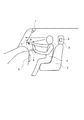
本発明の実施例について説明する。図1は本発明の実施例の操作装置100の概略図、図2は操作装置100のブロック図、図3は車両の前方風景を示す図、図4は曲線路において車両の前方風景を示す図である。 Examples of the present invention will be described. 1 is a schematic diagram of an operating device 100 according to an embodiment of the present invention, FIG. 2 is a block diagram of the operating device 100, FIG. 3 is a diagram showing a front landscape of the vehicle, and FIG. 4 is a diagram showing a front landscape of the vehicle on a curved road. It is.
図1及び図2に示されるように、本発明の実施例の操作装置100は、車両(本実施例の場合、自動車)におけるインストルメントパネルの近傍に仮想的に設けられたディスプレイ1(表示手段)と、運転席2のヘッドレスト3の部分に設置され、車両の前方風景を撮影する前方風景撮影カメラ4(前方風景画像取得手段)と、ディスプレイ1のほぼ直上に設置され、運転者5の指6を撮影してその座標位置を検出する操作指撮影カメラ7(操作指検知手段)とを備えている。なお、図1において、8はハンドルである。 As shown in FIGS. 1 and 2, the operating device 100 according to the embodiment of the present invention includes a display 1 (display means) virtually provided in the vicinity of an instrument panel in a vehicle (in the case of the present embodiment, an automobile). ), A front landscape photographing camera 4 (front landscape image acquisition means) that captures a front landscape of the vehicle, and is installed almost directly above the display 1, And an operation finger photographing camera 7 (operation finger detection means) for photographing 6 and detecting its coordinate position. In FIG. 1, 8 is a handle.
ディスプレイ1には、ナビゲーション装置9やエアコン(図示せず)等の車載機器を操作するためのボタンやスイッチ(以下、総称して「スイッチ類10」(投影画像要素)と記載する。)が、車両のフロントウィンドウ11に重畳して仮想的に表示される。運転者5は、ディスプレイ1に表示されたスイッチ類10を自身の指6で操作する。このときの指6が操作指撮影カメラ7によって撮影され、その座標位置が検知される。そして、ECU13(制御手段。図2参照)により、指6の座標位置とディスプレイ1に表示されたスイッチ類10の位置とが比較され、運転者5がディスプレイ1上のスイッチ類10を操作したかどうかを判断する。
The display 1 includes buttons and switches (hereinafter collectively referred to as “
図3に示されるように、前方風景撮影カメラ4により、フロントウィンドウ11を透視して見られる前方風景が撮影される。この前方風景撮影カメラ4は、運転状態の運転者5の視線とほぼ同一となるように、運転席2のヘッドレスト3に設置することが望ましい。また、フロントウィンドウ11を通して視認されるすべての前方風景を撮影できるように、一対の前方風景撮影カメラ4をヘッドレスト3の両側に設置し、一対の前方風景撮影カメラ4によって撮影された2枚の画像を合成してもよい。撮影された前方風景は、画像処理部12で所定の画像処理がなされてECU13に取り込まれる。撮影された前方風景には、各種の情報を備えている。図3に示される前方風景の場合、道路情報板14、道路標識15、路面の陥没穴16、障害物17、センターライン18、歩道との境界線19、建物20、太陽21、太陽光線を反射した建物20のガラス22、同じく路面23、同じく雪塊24、対向車のヘッドライト25の情報を備えている。
As shown in FIG. 3, the forward
ここで、車両が直線道路を走行する場合、スイッチ類10は、フロントウィンドウ11の右下部(この位置を、スイッチ類10の「デフォルト位置」と記載する。)に表示される。しかし、車両が道路の曲線部分(クランク路を含む)を走行する場合、運転者5は、車両の直前方の領域よりも、車両が曲がろうとする先の領域を視認する。このため、車両が曲線部分を走行しようとする場合にも、スイッチ類10をデフォルト位置に表示すると、運転者5の視線の移動が大きくなってしまう。これを回避するため、本実施例の操作装置100では、車両が走行する道路の稜線や白線(センターライン18や歩道との境界線19)を検出することにより、道路が直線路であるか曲線路であるかを判別している。そして、図4に示されるように、道路が曲線路である場合は、運転者5の視認領域の変化に追随させて、スイッチ類10を、車両が曲がろうとする先の領域に移動させる(後述)。
Here, when the vehicle travels on a straight road, the
本実施例の操作装置100の作用について説明する。運転者5が車両のキースイッチ(図示せず)をオンにすると、ディスプレイ1と操作指撮影カメラ7が作動する。これにより、ディスプレイ1上に車載機器(例えば、ナビゲーション装置9やエアコン)のスイッチ類10が、フロントウィンドウ11に重畳して表示される(図3参照)。キースイッチをオンにしたとき、スイッチ類10は、フロントウィンドウ11の右下部(デフォルト位置)に表示される。運転者5は、フロントウィンドウ11を視認する視線を大きく移動させることなく、スイッチ類10を視認できる。運転者5がディスプレイ1のスイッチ類10を操作すると、運転者5の指6が操作指撮影カメラ7に撮影され、その座標位置が検知される。
The operation of the operating device 100 according to the present embodiment will be described. When the
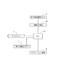
図5に示されるように、前方風景撮影カメラ4によって撮影された車両の前方風景は、画像データとしてECU13に取り込まれる(ステップS1)。この画像データには、運転者5が視認する情報として、道路情報板14、道路標識15、路面の陥没穴16、障害物17、センターライン18、歩道との境界線19、建物20、太陽21、太陽光線を反射した建物20のガラス22、同じく路面23、同じく雪塊24、対向車のヘッドライト25が表示されている。
As shown in FIG. 5, the front scenery of the vehicle photographed by the front
これらの情報は、画像処理部12で画像処理される(ステップS2)。即ち、これらの情報を、運転者5が視認しなければならない情報(道路情報板14、道路標識15、路面の陥没穴16、障害物17。以下、これらを「第1情報」と記載する。)と、運転者5が視認したくない情報(太陽21、太陽光線を反射した建物20のガラス22、同じく路面23、同じく雪塊24、対向車のヘッドライト25。以下、これらを「第2情報」と記載する。)と、道路の情報(センターライン18、歩道との境界線19。以下、これらを「第3情報」と記載する。)とに分別する。第1情報は、画像処理部12でそれらを画像処理することによって認識する。また、第2情報は、画像処理部12で輝度の大小を計測することによって認識する。そして、図6に示されるように、画像処理された取込み画像から、第1及び第2の情報の表示領域を抽出する。各表示領域を、対応する情報を示す符号に添え字「a」を付して記載する。
These pieces of information are subjected to image processing by the image processing unit 12 (step S2). In other words, these pieces of information must be visually recognized by the driver 5 (
次に、第3情報を認識することにより、現在走行中の道路が直線路であるか曲線路であるかを判断し、前方の路面を予測する(ステップS3)。直線路であるならば(ステップS3の「Yes」)、スイッチ類10をデフォルト位置に表示する(ステップS4)。そして、第1及び第2の情報の表示領域とスイッチ類10とが重なっているかどうかを確認する(ステップS5)。もし、第1及び第2の情報の表示領域とスイッチ類10とが重なっていない場合(ステップS5の「No」)、スイッチ類10をデフォルト位置にそのまま表示する(ステップS6)。もし、第1及び第2の情報の表示領域とスイッチ類10とが重なっている場合(ステップS5の「Yes」)、スイッチ類10を移動させる領域があるかどうかを調べる(ステップS7)。スイッチ類10を移動させる領域があれば(ステップS7の「Yes」)、図7に示されるように、スイッチ類10をデフォルト位置から移動させ、第1及び第2の情報の表示領域(図7の場合、路面の陥没穴16)と重ならないようにして表示する(ステップS8)。スイッチ類10を移動させる領域がなく(ステップS7の「No」)、スイッチ類10が第1情報の表示領域と重なっているのであれば、スイッチ類10を透過表示する(ステップS9)。これにより、スイッチ類10を通して第1情報を視認できる。また、スイッチ類10が第2情報の表示領域と重なっているのであれば、スイッチ類10を強調表示する(ステップS9)。これにより、スイッチ類10が第2情報によって視認しにくくなることを回避できる。
Next, by recognizing the third information, it is determined whether the currently traveling road is a straight road or a curved road, and a road surface ahead is predicted (step S3). If it is a straight road (“Yes” in step S3), the
ステップS3において道路が曲線部分であるならば(ステップS3の「No」)、スイッチ類10を、車両が曲がろうとする先にスイッチ類10を表示する(ステップS10)。以下のステップS11〜S15の作用は、道路が直線路であるときのステップS5〜S9までの作用と全く同一である。
If the road is a curved portion in step S3 ("No" in step S3), the
本実施例の操作装置100では、前方風景撮影カメラ4によって撮影された前方風景の画像データとスイッチ類10とは、それらの表示状態が交互に繰り返される時分割表示制御を行っている。図8に示されるように、ディスプレイ1には、スイッチ類10が表示されている。この状態を「A」で示す。そして、前方風景撮影カメラ4が前方風景を撮影するときに、ディスプレイ1へのスイッチ類10の表示を停止する。この状態を「B」で示す。これにより、撮影された前方風景にスイッチ類10が映り込むことはない。そして、再びスイッチ類10をディスプレイ1に表示する。スイッチ類10がディスプレイ1に表示されている間に、前方風景撮影カメラ4によって撮影された前方風景が画像データとして取り込まれ、回避対象領域を抽出し、重なり状態を確認し、必要に応じてスイッチ類10の表示位置を移動する作業が行われる。「A」及び「B」の時間は、運転者5が認識することが困難な微小時間に行われるため、運転者5には、スイッチ類10が連続して移動しているように見え、運転操作に支障をきたすおそれはない。
In the operating device 100 according to the present embodiment, the image data of the front scenery photographed by the front
本実施例では、車両の前方風景を、前方風景撮影カメラ4で撮影した画像を画像処理することによって取得している。しかし、ナビゲーション装置9の地図情報から前方風景画像を取得してもよい。
In this embodiment, the front landscape of the vehicle is acquired by performing image processing on an image captured by the front
本実施例の操作装置100では、前方風景における各情報とスイッチ類10とか重なっているか否かを判断している。これに加えて、車内情報とスイッチ類10との重なりをも判断して、スイッチ類10をデフォルト位置から移動させるようにしてもよい。車内情報として、例えば、ルームランプによる映り込みが想定される。
In the operating device 100 according to the present embodiment, it is determined whether or not each piece of information in the front landscape overlaps the
また、車両が加速中、減速中、旋回中の情報を取得することにより、スイッチ類10の表示位置を、運転者5に一層視認し易い位置に配置させることができる。例えば、車両が加速中であればスイッチ類10をより前方に表示したり、車両が減速中であればスイッチ類10を少し手前側に表示したり、車両が旋回中であればスイッチ類10を旋回方向に表示したりすることができる。
In addition, by acquiring information on whether the vehicle is accelerating, decelerating, or turning, the display position of the
100 操作装置
1 ディスプレイ(表示手段)
4 前方風景撮影カメラ(前方風景画像取得手段)
5 運転者
6 指
7 操作指撮影カメラ(操作指検知手段)
10 スイッチ類(投影画像要素)
11 フロントウィンドウ
12 画像処理部(画像処理手段)
13 ECU(制御手段)
14 道路情報板(回避対象領域)
15 道路標識(回避対象領域)
16 陥没穴(回避対象領域)
17 障害物(回避対象領域)
21 太陽(回避対象領域)
22 太陽光線を反射した建物のガラス(回避対象領域)
23 太陽光線を反射した路面(回避対象領域)
24 太陽光線を反射した雪塊(回避対象領域)
25 ヘッドライト(回避対象領域)
100 Operating device 1 Display (display means)
4 Front landscape camera (Front landscape image acquisition means)
5 Driver 6
10 Switches (projection image elements)
11
13 ECU (control means)
14 Road information board (area to avoid)
15 road signs (areas to avoid)
16 Sinkhole (area to avoid)
17 Obstacle (Avoidance target area)
21 Sun (area to avoid)
22 Building glass reflecting sunlight (area to avoid)
23 Road surface that reflects sunlight (area to avoid)
24 Snow mass reflecting sun rays (area to avoid)
25 Headlight (Avoidance target area)
Claims (6)
前記車両の運転者が指で前記投影画像要素を操作したことを検知する操作指検知手段と、
前記車両の前方風景を撮影し、前方風景画像を取得する前方風景画像取得手段と、
前記取得された前方風景画像から予め設定された回避対象領域を抽出する画像処理手段と、
前記表示手段における前記投影画像要素の表示位置が、前記前方風景画像から抽出された回避対象領域と重なっているときにその表示位置を移動させたり、その表示方法を異ならせたりする制御を行う制御手段と、
を備えることを特徴とする車載機器の操作装置。 Display means for virtually displaying buttons, switches and other projection image elements installed on or near the front window of the vehicle for operating equipment mounted on the vehicle in a state of being superimposed on the front window;
Operation finger detection means for detecting that the driver of the vehicle has operated the projection image element with a finger;
Forward landscape image acquisition means for capturing a forward landscape image of the vehicle and acquiring a forward landscape image;
Image processing means for extracting a preset avoidance target area from the acquired forward landscape image;
Control for performing control to move the display position or to change the display method when the display position of the projection image element on the display unit overlaps the avoidance target area extracted from the forward landscape image Means,
A device for operating an in-vehicle device.
Priority Applications (1)
| Application Number | Priority Date | Filing Date | Title |
|---|---|---|---|
| JP2008078585A JP5136950B2 (en) | 2008-03-25 | 2008-03-25 | In-vehicle device operation device |
Applications Claiming Priority (1)
| Application Number | Priority Date | Filing Date | Title |
|---|---|---|---|
| JP2008078585A JP5136950B2 (en) | 2008-03-25 | 2008-03-25 | In-vehicle device operation device |
Publications (2)
| Publication Number | Publication Date |
|---|---|
| JP2009227245A true JP2009227245A (en) | 2009-10-08 |
| JP5136950B2 JP5136950B2 (en) | 2013-02-06 |
Family
ID=41243144
Family Applications (1)
| Application Number | Title | Priority Date | Filing Date |
|---|---|---|---|
| JP2008078585A Expired - Fee Related JP5136950B2 (en) | 2008-03-25 | 2008-03-25 | In-vehicle device operation device |
Country Status (1)
| Country | Link |
|---|---|
| JP (1) | JP5136950B2 (en) |
Cited By (14)
| Publication number | Priority date | Publication date | Assignee | Title |
|---|---|---|---|---|
| JP2013203374A (en) * | 2012-03-29 | 2013-10-07 | Denso It Laboratory Inc | Display device for vehicle, control method therefor, and program |
| JP2015032085A (en) * | 2013-08-01 | 2015-02-16 | セイコーエプソン株式会社 | Display device, head-mounted display device, display system, and control method of display device |
| JP2016104603A (en) * | 2014-12-01 | 2016-06-09 | 日本精機株式会社 | Display system for vehicle |
| JP2017170933A (en) * | 2016-03-18 | 2017-09-28 | 株式会社Subaru | Vehicle display control device |
| JP2017170934A (en) * | 2016-03-18 | 2017-09-28 | 株式会社Subaru | Vehicle display control device |
| JP2017182814A (en) * | 2012-06-29 | 2017-10-05 | ノキア テクノロジーズ オサケユイチア | Method and apparatus for modification of presentation of information based on visual complexity of environment information |
| US9886796B2 (en) | 2013-08-02 | 2018-02-06 | Seiko Epson Corporation | Display device, head mounted display, display system, and control method for display device |
| JP2019001459A (en) * | 2018-07-25 | 2019-01-10 | パイオニア株式会社 | Display device |
| JPWO2018110045A1 (en) * | 2016-12-14 | 2019-10-24 | 富士フイルム株式会社 | Projection display device, control method and control program for projection display device |
| JP2020093784A (en) * | 2020-02-10 | 2020-06-18 | パイオニア株式会社 | Display device |
| JP2020112698A (en) * | 2019-01-11 | 2020-07-27 | 株式会社リコー | Display control device, display unit, display system, movable body, program, and image creation method |
| CN112319467A (en) * | 2019-07-31 | 2021-02-05 | 丰田研究所股份有限公司 | Autonomous vehicle user interface with predicted trajectory |
| JP2022058623A (en) * | 2013-03-25 | 2022-04-12 | Case特許株式会社 | vehicle |
| WO2022249230A1 (en) * | 2021-05-24 | 2022-12-01 | 三菱電機株式会社 | Control device, control method, and in-vehicle device |
Citations (5)
| Publication number | Priority date | Publication date | Assignee | Title |
|---|---|---|---|---|
| JPH0876050A (en) * | 1994-09-05 | 1996-03-22 | Fujitsu Ten Ltd | Display device for vehicle |
| JPH10311732A (en) * | 1997-05-09 | 1998-11-24 | Toyota Motor Corp | Display device for vehicle |
| JP2002019491A (en) * | 2000-07-11 | 2002-01-23 | Mazda Motor Corp | Display device of vehicle |
| JP2005069799A (en) * | 2003-08-22 | 2005-03-17 | Denso Corp | Navigation system for vehicle |
| JP2007296889A (en) * | 2006-04-28 | 2007-11-15 | Honda Motor Co Ltd | Operation device of on-vehicle equipment |
-
2008
- 2008-03-25 JP JP2008078585A patent/JP5136950B2/en not_active Expired - Fee Related
Patent Citations (5)
| Publication number | Priority date | Publication date | Assignee | Title |
|---|---|---|---|---|
| JPH0876050A (en) * | 1994-09-05 | 1996-03-22 | Fujitsu Ten Ltd | Display device for vehicle |
| JPH10311732A (en) * | 1997-05-09 | 1998-11-24 | Toyota Motor Corp | Display device for vehicle |
| JP2002019491A (en) * | 2000-07-11 | 2002-01-23 | Mazda Motor Corp | Display device of vehicle |
| JP2005069799A (en) * | 2003-08-22 | 2005-03-17 | Denso Corp | Navigation system for vehicle |
| JP2007296889A (en) * | 2006-04-28 | 2007-11-15 | Honda Motor Co Ltd | Operation device of on-vehicle equipment |
Cited By (19)
| Publication number | Priority date | Publication date | Assignee | Title |
|---|---|---|---|---|
| JP2013203374A (en) * | 2012-03-29 | 2013-10-07 | Denso It Laboratory Inc | Display device for vehicle, control method therefor, and program |
| JP2017182814A (en) * | 2012-06-29 | 2017-10-05 | ノキア テクノロジーズ オサケユイチア | Method and apparatus for modification of presentation of information based on visual complexity of environment information |
| JP2022058623A (en) * | 2013-03-25 | 2022-04-12 | Case特許株式会社 | vehicle |
| JP2015032085A (en) * | 2013-08-01 | 2015-02-16 | セイコーエプソン株式会社 | Display device, head-mounted display device, display system, and control method of display device |
| US9857588B2 (en) | 2013-08-01 | 2018-01-02 | Seiko Epson Corporation | Display device, head mounted display, display system, and control method for display device |
| US9886796B2 (en) | 2013-08-02 | 2018-02-06 | Seiko Epson Corporation | Display device, head mounted display, display system, and control method for display device |
| JP2016104603A (en) * | 2014-12-01 | 2016-06-09 | 日本精機株式会社 | Display system for vehicle |
| DE102017103287B4 (en) | 2016-03-18 | 2022-03-03 | Subaru Corporation | DISPLAY CONTROL FOR A VEHICLE |
| JP2017170933A (en) * | 2016-03-18 | 2017-09-28 | 株式会社Subaru | Vehicle display control device |
| JP2017170934A (en) * | 2016-03-18 | 2017-09-28 | 株式会社Subaru | Vehicle display control device |
| US10564434B2 (en) | 2016-03-18 | 2020-02-18 | Subaru Corporation | Display control device for vehicle |
| JPWO2018110045A1 (en) * | 2016-12-14 | 2019-10-24 | 富士フイルム株式会社 | Projection display device, control method and control program for projection display device |
| JP2019001459A (en) * | 2018-07-25 | 2019-01-10 | パイオニア株式会社 | Display device |
| JP2020112698A (en) * | 2019-01-11 | 2020-07-27 | 株式会社リコー | Display control device, display unit, display system, movable body, program, and image creation method |
| CN112319467A (en) * | 2019-07-31 | 2021-02-05 | 丰田研究所股份有限公司 | Autonomous vehicle user interface with predicted trajectory |
| CN112319467B (en) * | 2019-07-31 | 2023-04-14 | 丰田研究所股份有限公司 | Autonomous vehicle user interface with predicted trajectory |
| JP2021183490A (en) * | 2020-02-10 | 2021-12-02 | パイオニア株式会社 | Display device |
| JP2020093784A (en) * | 2020-02-10 | 2020-06-18 | パイオニア株式会社 | Display device |
| WO2022249230A1 (en) * | 2021-05-24 | 2022-12-01 | 三菱電機株式会社 | Control device, control method, and in-vehicle device |
Also Published As
| Publication number | Publication date |
|---|---|
| JP5136950B2 (en) | 2013-02-06 |
Similar Documents
| Publication | Publication Date | Title |
|---|---|---|
| JP5136950B2 (en) | In-vehicle device operation device | |
| JP6346614B2 (en) | Information display system | |
| KR102206272B1 (en) | Parking assistance method and parking assistance device | |
| CN107206934B (en) | Imaing projector | |
| JP6123761B2 (en) | Vehicle display device | |
| EP2487906B1 (en) | Control device and vehicle surrounding monitoring device | |
| JP6272375B2 (en) | Display control device for vehicle | |
| JP6413207B2 (en) | Vehicle display device | |
| JP5035643B2 (en) | Image display device | |
| US20150302259A1 (en) | Driving assistance device and image processing program | |
| JP4943367B2 (en) | Vehicle information display device | |
| JP2010130646A (en) | Vehicle periphery checking system | |
| JP2003200755A (en) | Displaying device for vehicle | |
| JP5916541B2 (en) | In-vehicle system | |
| JP6674793B2 (en) | Driving support information display device | |
| JP2010130647A (en) | Vehicle periphery checking system | |
| JP2005136561A (en) | Vehicle peripheral picture display device | |
| JP6448714B2 (en) | Information display system | |
| JP6186905B2 (en) | In-vehicle display device and program | |
| CN110462699B (en) | Display control device for vehicle and display unit for vehicle | |
| WO2016056199A1 (en) | Head-up display device, and display method for head-up display | |
| JP2007230491A (en) | Visual sense information presentation device and visual sense information presentation method | |
| CN109421535B (en) | Display device for vehicle and display control method | |
| CN113448097B (en) | Display device for vehicle | |
| JP2010064646A (en) | Device and method for monitoring vehicle periphery |
Legal Events
| Date | Code | Title | Description |
|---|---|---|---|
| A621 | Written request for application examination |
Free format text: JAPANESE INTERMEDIATE CODE: A621 Effective date: 20100804 |
|
| A977 | Report on retrieval |
Free format text: JAPANESE INTERMEDIATE CODE: A971007 Effective date: 20120531 |
|
| A131 | Notification of reasons for refusal |
Free format text: JAPANESE INTERMEDIATE CODE: A131 Effective date: 20120604 |
|
| A521 | Request for written amendment filed |
Free format text: JAPANESE INTERMEDIATE CODE: A523 Effective date: 20120720 |
|
| RD02 | Notification of acceptance of power of attorney |
Free format text: JAPANESE INTERMEDIATE CODE: A7422 Effective date: 20121002 |
|
| TRDD | Decision of grant or rejection written | ||
| A01 | Written decision to grant a patent or to grant a registration (utility model) |
Free format text: JAPANESE INTERMEDIATE CODE: A01 Effective date: 20121022 |
|
| A01 | Written decision to grant a patent or to grant a registration (utility model) |
Free format text: JAPANESE INTERMEDIATE CODE: A01 |
|
| R151 | Written notification of patent or utility model registration |
Ref document number: 5136950 Country of ref document: JP Free format text: JAPANESE INTERMEDIATE CODE: R151 |
|
| A61 | First payment of annual fees (during grant procedure) |
Free format text: JAPANESE INTERMEDIATE CODE: A61 Effective date: 20121104 |
|
| FPAY | Renewal fee payment (event date is renewal date of database) |
Free format text: PAYMENT UNTIL: 20151122 Year of fee payment: 3 |
|
| R250 | Receipt of annual fees |
Free format text: JAPANESE INTERMEDIATE CODE: R250 |
|
| R250 | Receipt of annual fees |
Free format text: JAPANESE INTERMEDIATE CODE: R250 |
|
| R250 | Receipt of annual fees |
Free format text: JAPANESE INTERMEDIATE CODE: R250 |
|
| R250 | Receipt of annual fees |
Free format text: JAPANESE INTERMEDIATE CODE: R250 |
|
| R250 | Receipt of annual fees |
Free format text: JAPANESE INTERMEDIATE CODE: R250 |
|
| R250 | Receipt of annual fees |
Free format text: JAPANESE INTERMEDIATE CODE: R250 |
|
| LAPS | Cancellation because of no payment of annual fees |