WO2015148511A1 - Environmental control apparatus and related methods - Google Patents
Environmental control apparatus and related methods Download PDFInfo
- Publication number
- WO2015148511A1 WO2015148511A1 PCT/US2015/022255 US2015022255W WO2015148511A1 WO 2015148511 A1 WO2015148511 A1 WO 2015148511A1 US 2015022255 W US2015022255 W US 2015022255W WO 2015148511 A1 WO2015148511 A1 WO 2015148511A1
- Authority
- WO
- WIPO (PCT)
- Prior art keywords
- user
- controller
- exemplary
- microprocessor
- control apparatus
- Prior art date
Links
- 238000000034 method Methods 0.000 title description 5
- 230000007613 environmental effect Effects 0.000 title description 4
- 238000004891 communication Methods 0.000 claims abstract description 13
- 230000008859 change Effects 0.000 claims description 6
- 230000009471 action Effects 0.000 claims description 3
- 238000010079 rubber tapping Methods 0.000 claims description 2
- 238000001816 cooling Methods 0.000 description 9
- 230000001276 controlling effect Effects 0.000 description 8
- 238000013461 design Methods 0.000 description 6
- 238000010438 heat treatment Methods 0.000 description 6
- XUIMIQQOPSSXEZ-UHFFFAOYSA-N Silicon Chemical compound [Si] XUIMIQQOPSSXEZ-UHFFFAOYSA-N 0.000 description 4
- 230000003993 interaction Effects 0.000 description 4
- 230000015654 memory Effects 0.000 description 4
- 229910052710 silicon Inorganic materials 0.000 description 4
- 239000010703 silicon Substances 0.000 description 4
- HBBGRARXTFLTSG-UHFFFAOYSA-N Lithium ion Chemical compound [Li+] HBBGRARXTFLTSG-UHFFFAOYSA-N 0.000 description 3
- 238000001514 detection method Methods 0.000 description 3
- 238000009434 installation Methods 0.000 description 3
- 229910001416 lithium ion Inorganic materials 0.000 description 3
- 239000004606 Fillers/Extenders Substances 0.000 description 2
- 238000010586 diagram Methods 0.000 description 2
- 239000000463 material Substances 0.000 description 2
- 238000012986 modification Methods 0.000 description 2
- 230000004048 modification Effects 0.000 description 2
- 230000001105 regulatory effect Effects 0.000 description 2
- DNTFEAHNXKUSKQ-RFZPGFLSSA-N (1r,2r)-2-aminocyclopentane-1-sulfonic acid Chemical compound N[C@@H]1CCC[C@H]1S(O)(=O)=O DNTFEAHNXKUSKQ-RFZPGFLSSA-N 0.000 description 1
- 241000282472 Canis lupus familiaris Species 0.000 description 1
- RYGMFSIKBFXOCR-UHFFFAOYSA-N Copper Chemical compound [Cu] RYGMFSIKBFXOCR-UHFFFAOYSA-N 0.000 description 1
- CYTYCFOTNPOANT-UHFFFAOYSA-N Perchloroethylene Chemical compound ClC(Cl)=C(Cl)Cl CYTYCFOTNPOANT-UHFFFAOYSA-N 0.000 description 1
- 230000008901 benefit Effects 0.000 description 1
- 239000003086 colorant Substances 0.000 description 1
- 238000010276 construction Methods 0.000 description 1
- 229910052802 copper Inorganic materials 0.000 description 1
- 239000010949 copper Substances 0.000 description 1
- 238000011161 development Methods 0.000 description 1
- 230000000694 effects Effects 0.000 description 1
- 238000005516 engineering process Methods 0.000 description 1
- 230000006870 function Effects 0.000 description 1
- 238000003780 insertion Methods 0.000 description 1
- 230000037431 insertion Effects 0.000 description 1
- 238000011900 installation process Methods 0.000 description 1
- 230000006855 networking Effects 0.000 description 1
- 238000012797 qualification Methods 0.000 description 1
- 230000011664 signaling Effects 0.000 description 1
- 239000007787 solid Substances 0.000 description 1
- 238000001228 spectrum Methods 0.000 description 1
- 238000012360 testing method Methods 0.000 description 1
- 230000002618 waking effect Effects 0.000 description 1
- 239000002699 waste material Substances 0.000 description 1
Classifications
-
- F—MECHANICAL ENGINEERING; LIGHTING; HEATING; WEAPONS; BLASTING
- F24—HEATING; RANGES; VENTILATING
- F24F—AIR-CONDITIONING; AIR-HUMIDIFICATION; VENTILATION; USE OF AIR CURRENTS FOR SCREENING
- F24F11/00—Control or safety arrangements
- F24F11/30—Control or safety arrangements for purposes related to the operation of the system, e.g. for safety or monitoring
-
- F—MECHANICAL ENGINEERING; LIGHTING; HEATING; WEAPONS; BLASTING
- F24—HEATING; RANGES; VENTILATING
- F24F—AIR-CONDITIONING; AIR-HUMIDIFICATION; VENTILATION; USE OF AIR CURRENTS FOR SCREENING
- F24F11/00—Control or safety arrangements
- F24F11/50—Control or safety arrangements characterised by user interfaces or communication
- F24F11/52—Indication arrangements, e.g. displays
- F24F11/523—Indication arrangements, e.g. displays for displaying temperature data
-
- F—MECHANICAL ENGINEERING; LIGHTING; HEATING; WEAPONS; BLASTING
- F24—HEATING; RANGES; VENTILATING
- F24F—AIR-CONDITIONING; AIR-HUMIDIFICATION; VENTILATION; USE OF AIR CURRENTS FOR SCREENING
- F24F11/00—Control or safety arrangements
- F24F11/62—Control or safety arrangements characterised by the type of control or by internal processing, e.g. using fuzzy logic, adaptive control or estimation of values
- F24F11/63—Electronic processing
-
- G—PHYSICS
- G05—CONTROLLING; REGULATING
- G05B—CONTROL OR REGULATING SYSTEMS IN GENERAL; FUNCTIONAL ELEMENTS OF SUCH SYSTEMS; MONITORING OR TESTING ARRANGEMENTS FOR SUCH SYSTEMS OR ELEMENTS
- G05B15/00—Systems controlled by a computer
- G05B15/02—Systems controlled by a computer electric
-
- G—PHYSICS
- G05—CONTROLLING; REGULATING
- G05D—SYSTEMS FOR CONTROLLING OR REGULATING NON-ELECTRIC VARIABLES
- G05D23/00—Control of temperature
- G05D23/19—Control of temperature characterised by the use of electric means
- G05D23/1902—Control of temperature characterised by the use of electric means characterised by the use of a variable reference value
- G05D23/1905—Control of temperature characterised by the use of electric means characterised by the use of a variable reference value associated with tele control
-
- H—ELECTRICITY
- H05—ELECTRIC TECHNIQUES NOT OTHERWISE PROVIDED FOR
- H05B—ELECTRIC HEATING; ELECTRIC LIGHT SOURCES NOT OTHERWISE PROVIDED FOR; CIRCUIT ARRANGEMENTS FOR ELECTRIC LIGHT SOURCES, IN GENERAL
- H05B47/00—Circuit arrangements for operating light sources in general, i.e. where the type of light source is not relevant
- H05B47/10—Controlling the light source
- H05B47/105—Controlling the light source in response to determined parameters
- H05B47/115—Controlling the light source in response to determined parameters by determining the presence or movement of objects or living beings
- H05B47/12—Controlling the light source in response to determined parameters by determining the presence or movement of objects or living beings by detecting audible sound
-
- H—ELECTRICITY
- H05—ELECTRIC TECHNIQUES NOT OTHERWISE PROVIDED FOR
- H05B—ELECTRIC HEATING; ELECTRIC LIGHT SOURCES NOT OTHERWISE PROVIDED FOR; CIRCUIT ARRANGEMENTS FOR ELECTRIC LIGHT SOURCES, IN GENERAL
- H05B47/00—Circuit arrangements for operating light sources in general, i.e. where the type of light source is not relevant
- H05B47/10—Controlling the light source
- H05B47/175—Controlling the light source by remote control
- H05B47/19—Controlling the light source by remote control via wireless transmission
-
- H05B47/1965—
-
- F—MECHANICAL ENGINEERING; LIGHTING; HEATING; WEAPONS; BLASTING
- F24—HEATING; RANGES; VENTILATING
- F24F—AIR-CONDITIONING; AIR-HUMIDIFICATION; VENTILATION; USE OF AIR CURRENTS FOR SCREENING
- F24F11/00—Control or safety arrangements
- F24F11/50—Control or safety arrangements characterised by user interfaces or communication
- F24F11/52—Indication arrangements, e.g. displays
-
- F—MECHANICAL ENGINEERING; LIGHTING; HEATING; WEAPONS; BLASTING
- F24—HEATING; RANGES; VENTILATING
- F24F—AIR-CONDITIONING; AIR-HUMIDIFICATION; VENTILATION; USE OF AIR CURRENTS FOR SCREENING
- F24F11/00—Control or safety arrangements
- F24F11/50—Control or safety arrangements characterised by user interfaces or communication
- F24F11/56—Remote control
-
- F—MECHANICAL ENGINEERING; LIGHTING; HEATING; WEAPONS; BLASTING
- F24—HEATING; RANGES; VENTILATING
- F24F—AIR-CONDITIONING; AIR-HUMIDIFICATION; VENTILATION; USE OF AIR CURRENTS FOR SCREENING
- F24F2110/00—Control inputs relating to air properties
- F24F2110/10—Temperature
-
- F—MECHANICAL ENGINEERING; LIGHTING; HEATING; WEAPONS; BLASTING
- F24—HEATING; RANGES; VENTILATING
- F24F—AIR-CONDITIONING; AIR-HUMIDIFICATION; VENTILATION; USE OF AIR CURRENTS FOR SCREENING
- F24F2110/00—Control inputs relating to air properties
- F24F2110/20—Humidity
-
- Y—GENERAL TAGGING OF NEW TECHNOLOGICAL DEVELOPMENTS; GENERAL TAGGING OF CROSS-SECTIONAL TECHNOLOGIES SPANNING OVER SEVERAL SECTIONS OF THE IPC; TECHNICAL SUBJECTS COVERED BY FORMER USPC CROSS-REFERENCE ART COLLECTIONS [XRACs] AND DIGESTS
- Y02—TECHNOLOGIES OR APPLICATIONS FOR MITIGATION OR ADAPTATION AGAINST CLIMATE CHANGE
- Y02B—CLIMATE CHANGE MITIGATION TECHNOLOGIES RELATED TO BUILDINGS, e.g. HOUSING, HOUSE APPLIANCES OR RELATED END-USER APPLICATIONS
- Y02B20/00—Energy efficient lighting technologies, e.g. halogen lamps or gas discharge lamps
- Y02B20/40—Control techniques providing energy savings, e.g. smart controller or presence detection
Definitions
- One or more exemplary embodiments described herein comprise a thermostat apparatus in communication with one or more remote environmental sensors.
- the apparatus may raise or lower temperature in a particular room (or zone), for example, based on whether that room is currently occupied.
- the apparatus further may allow multiple zones to work in conjunction, instead of treating each zone separately.
- An exemplary aspect comprises a temperature control apparatus comprising: (a) microprocessor in communication with an HVAC control system; (b) a wireless transceiver in communication with the microprocessor and with a controller operable to communicate over a wireless network with an application on a mobile device; (c) a temperature sensor in communication with the microprocessor; and (d) a front panel that allows a user to interface with the controller.
- the wireless transceiver is in communication with the controller is a ZigBee transceiver; (2) the microprocessor is programmed by a user to perform one or more actions; (3) the temperature control apparatus further comprises an accelerometer; (4) the accelerometer is operable to allow the microprocessor detect tapping by a user on the front panel; and (5) the microprocessor is programmed so that a set number of taps by a user on the front panel results in a predetermined change in temperature settings.
- FIG. 1 depicts a configuration of an exemplary embodiment.
- FIG. 2 depicts an exemplary face plate of an embodiment.
- FIG. 3 depicts exemplary app screens of an embodiment.
- FIG. 4 depicts a controller that may be used with an exemplary embodiment.
- FIG. 5 depicts exemplary app screens for a controller that may be used with an exemplary embodiment.
- FIG. 1 A configuration of an exemplary embodiment is depicted in FIG. 1.
- This power converter may step down the 24V AC provided from the heating/cooling power lines to the correct DC voltage needed to run the apparatus and keep the backup battery charged and on standby.
- the temperature and humidity sensor allows the apparatus to serve as an additional sensing zone. This data can not only be used in heating and cooling the home but also can be used to drive other aspects of the smart home.
- This solution may route 24v via relays or emulation to the appropriate relays on the HVAC system.
- Those skilled in the art may appreciate that cost and efficiency may be the driver on selecting specific Relays or Emulation for signaling the 24V HVAC Control relays.
- 24V applied to Yl may turn on the Cooling system.
- Wire terminals allow the installation process to be quick and easy. Wires from the HVAC system are connected to the corresponding terminals by inserting wires in to the corresponding holes. This type of connector allows for easy insertion and removal of wires should the need arise.
- Backup Battery Example: Rechargable Lithium ion CR2450 3.6v, or Lithium ion flat pack
- This battery may be charged by the converted 24V AC coming in off of the HVAC system and may stand in should voltage not be adequate enough to run apparatus.
- Any suitable batteries or other power source may be used instead of Lithium ion batteries.
- Zigbee module for communication between The apparatus and external control devices, such as a controller, hub, or an app interface, allows for easy exchange of data and control.
- the module also acts as a passive extender for other Zigbee modules allowing the overall Zigbee network to increase in coverage area.
- the apparatus is designed to replace an existing thermostat, or in the case of new homes, be wired directly to an HVAC system, thus eliminating the need for expensive copper wiring.
- the apparatus may comprise 2 parts: (1) a wiring plate, which gets mounted to the wall and has terminals to accept the wires which control the HVAC system, as well as the front face; and (2) a face plate, which houses the electronic components and is the consumer side of the product. See FIG. 2.
- a multi-device controller such as that described in co-pending U.S. Pat. app. no. 14/667,127, entitled “CONTROL APPARATUS AND RELATED METHODS", may be used with one or embodiments. More details on such a controller are provided below in the Exemplary Controller section.
- Controlling the apparatus (designated "Project 2" in FIG. 3) from within a Wink app preferably is simple and intuitive. Building off of the platform's ability to utilize the back end for creating schedules, the user may be presented with a simple interface to view and adjust temperature manually, as well as fine tune schedules.
- the interface may allow for easy control of multiple zones by allowing the user to select which room they want to base temperature on, as well as which zone they are controlling in manual mode.
- the remote sensor for the thermostat may be the temperature and humidity sensor in the light switch (Controller) described above, and/or sensors in other products.
- the thermostat may cool or heat more based on which room has priority. This priority also may be based on a user's location in the home (as determined by cell phone, motion detection, etc.).
- the thermostat itself also has a temperature and humidity sensor and thus may correspond to its own heating/cooling zone. Scheduling may be a quick and painless activity for the user. The user may use a slider to select the room, temperature range, and time for this range to be active.
- Historical usage data may also be available to the user from within the Interface.
- An RBG LED may be used to reflect the different colors.
- the Main Screen may show basic information about the apparatus's current status. This may include the current temperature setting, ambient temperature in the heating/cooling zone the apparatus is installed in, and the current operation mode. If there are multiple apparatuses installed, the current temperatures of those may be included also.
- the home screen may also allow the user to toggle basic settings.
- These may include the mode that the apparatus is in - either heating, cooling, or fan only - and adjusting current temperature setting either hotter or colder.
- the Schedule screen offers a glimpse into how the HVAC system is going to be operated over the span of a specified time frame and allows a user to make adjustments based on preference or upcoming schedule.
- a schedule may be
- the History screen offers a glimpse into the user's heating and cooling usage. This information is easy to drill down by month / week / day and offers the user insight into how their schedules are being automatically created and the times at which their system is being most utilized.
- the user browser allows a user to add, remove and edit users. Adding a user:
- Controller displays BLE (Bluetooth Low Energy) devices within range.
- Controller prompts a user to create a username for a user profile.
- Controller lands a user on User Preference Screen to begin setting user preferences.
- Adding a user will display a modal view which searches for BLE compatible devices in the area.
- User Preferences allows a user to set up a Controller the way a user likes it, with the user's own Wink account, the user's own devices and the user's own Dashboard layouts.
- User Preferences may contain three sections (Dashboard, Devices, and Change Wink Account).
- Any widget with further customization should include a settings icon that displays a modal for setting up that additional configuration (adding a user's twitter account, for example).
- a list of devices may be assigned to a user's account and made available for the user to control.
- Any device controllable with On/Off triggers can be grouped together to be controlled together with a single action.
- Each device and group can be assigned to a physical button and displayed or hidden in an "Alternate Device Callout" with a check box.
- This button allows a user to disassociate a user profile with account and sign into another.
- the 1 or 2 connected loads may be the main focus of the screen. There may be an interface for switching these two off and on with extreme ease (single tap on/off).
- This screen may be a duplicate of the Local Control Screen for that room.
- This may reset after x number of seconds so that someone doesn't enter the room and control the wrong room. The user may not have to hit a "back button.”
- Additional devices may be selected by the user to appear in the bottom of the control screen.
- a scrollable marquee may be located toward the bottom of the screen.
- a user may slide these until locating the device a user would like to control and selecting it with a tap.
- the last icon in this list may be a "+" to add more devices. This may load a user's existing Wink account device list and provide the ability to add more devices via discovered Zigbee (IEEE 802.15.4) devices as well as Wifi devices, depending on how each is configured.
- Permissions allow a user to specify who can access what and when.
- Permissions allow a user to specify who can access what and when.
- This board allows the system to run Android as the underlying OS and launch a custom build of the wink app.
- This app may be catered to this application but allow for the addition of all products compatible with the wink ecosystem.
- the central interaction point of the product, the touch screen is where most of the interaction happens.
- a personalized dashboard as a user default, a quick touch switches to the switch screen, allowing control of the local loads the switch replaced, as well as any other components.
- Bluetooth / WIFI Combo Chip (Semco SWB-B53 based on Broadcom
- this chip allows for Bluetooth and BLE connectivity which opens up an entire new spectrum of products the Wink platform can take advantage of.
- Bluetooth while as stated, allows control of other products, it may also allow other Bluetooth devices to control the light switch.
- BLE allows the system to serve custom experiences based on who is standing at the panel, as their phone will be recognized.
- the WIFI capability provides for connectivity to the Internet via a local router.
- Zigbee enables support for existing products such as wireless light bulbs (Philips Hue, etc.) as well as development of future products.
- the use of Zigbee also acts as a passive extender for other Zigbee products the user may already own, thus increasing the range in which their existing products work with each other.
- Switches can control the local loads on them (the lights a user switches were tied to) and also can be configured to control virtually any smart product that reacts to on/off etc. (Garage Door, Smart light bulbs located anywhere [and not just one], Pivot Power Genius). The satisfying click lets a user know the button was pressed and is a quick way to interact with a user's home without having to interact with the screen if a user is on the go. Motion/Prox Sensor
- the IR Sensor is how the switch knows a user is coming up to interact. This gives the switch time to wake up and provide a user with the info or control a user needs immediately without a user having to waste time waking the unit up.
- any suitable motion or position sensor may be used instead of an IR sensor.
- the A/C Relays are switches.
- the switch is wired to replace 1 or 2 switches with the same SKU.
- the Relay when given the signal, switches the local loads on and off. This signal can come from the local buttons, the touch screen, or any other device running the wink app.
- the converter may be how the apparatus is powered.
- the AC power from the gang box is converted to DC.
- the microphone gives control opportunity as well as the ability to incorporate an internal intercom system. Voice commands may be used, and other sounds may be recognized (doors opening/closing, dogs barking, etc.).
- the speaker may allow for intercom operability as well as give the device a personality and voice, as well as reminders and audible alerts.
- the device may support two mechanical buttons for controlling either local or remote loads; S/W configurable via GPIO
- the device may attempt to fit into a North American single gang and double gang wall receptacle
- the device may provide three positions for the power box to be placed - to right, center, or to left.
- FIG. 4 shows exemplary high level architecture of the controller and power box.
- the device may use a Freescale i.MX6 family processor supporting Android OS framework. [PR-001 ] (PR citations refer to TABLE 2 below).
- the device may support the following system memory [PR-002] :
- Semco SWB-B53 module based on Broadcom BCM4334 may be used to support IEEE 802.11 g/n and Bluetooth 4.0 LE. [PR-003]
- the testing and qualification of the device may be based on 802.11 g and n.
- the device may use the 2.4 GHz frequency band for 802.11 n. [PR-005]
- the device may support both 20MHz and 40MHz bandwidth at IEEE 802.1 In. [PR-1)
- the lightswitch may support Bluetooth 4.0 LE.
- the WiFi Bluetooth coexistence may be handled by the SWB-B53 module. [PR- 008]
- the device may have one antenna that is shared between WiFi and Bluetooth.
- the Zigbee functionality may be supported using Silicon Images EM357 Ember® ZigBee chip. [PR-010]
- the device may support the coexistence of Zigbee with WiFi and BT since both the technologies use 2.4 GHz ISM band. [PR-011]
- the device may support Zigbee mesh networking capability. [PR-012]
- the device may use a 4.3 inch or other TFT-LCD display panel.
- the device may have a built-in motion or proximity detection sensor to allow a user to wake up the display by, for example, waving hands 10 cm in front of display screen.
- the device may allow a detectable range of 4 to 5 ft with minimal latency.
- the device may have sensor(s) to enable the Smart Light Switch to collect room temperature and humidity information.
- the analog microphone and speaker may be interfaced with the Audio codec to the ⁇ . ⁇ 6 processor to provide intercom and voice notification feature.
- the AC relay switch may fit in the power box [PR-017]
- the AC-DC PSU may operate at AC input between lOOVAC to 240V AC
- the AC -DC PSU may fit in the power box [PR-019]
- the device may fit inside, cover, and mechanically affix to both North American single-gang and double-gang wall receptacles.
- Exemplary Single Gangbox - may have dimensions:
- Width 50mm, for example.
- Height 87mm, for example.
- Exemplary Double Gangbox - may have dimensions:
- Width 94mm, for example.
- Depth 70mm, for example.
- the power box and device may follow the NEMA code.
- the single gang box design may have two mechanical switches supporting following requirements [PR-021]:
- the device itself may have the two buttons to the right and programmable to control either the local load or other functions within the home.
- the device may have terminals for 2 loads; in a single-gang configuration, one may be empty.
- the single gangbox design with two switches is the nominal case.
- the nominal design may provide expandability support for the 3- and 4-gang plates.
- the mechanical button may, for example, have a feel similar to Omron's B3F-4005 tactile switch.
- the operating force may be, for example, 260g.
- the size of the switch may be, for example, 12.5 mm x 12.5 mm.
- the dome of the switch may be, for example, 8.4 mm in diameter.
- the device may have a built-in motion or proximity detection sensor to allow end user to wake up the display by waiving hands 10 cm in front of display screen.
- the device may allow a detectable range of 4 to 5 ft with minimal latency.
- the device may have sensor(s) to enable the Smart Light
- the analog microphone and speaker may be interfaced with the Audio codec to the i.MX6 processor to provide intercom and voice notification feature.
- the AC relay switch may fit in the power box
- the AC-DC PSU may operate at AC input between
- the AC-DC PSU may fit in the power box
- the device may fit inside, cover, and mechanically affix to both North American single-gang and double-gang wall receptacles.
- the single gang box design may have two mechanical switches supporting requirements in Section 3.4.6
- the 802.11 g/n may support minimum data rate of 0.25
- the device may comply with the environmental conditions
- the device may comply with the reliability requirements as described in Section 5.2.
- the device may comply with the regulatory compliance requirements to place the product in the US market.
- the device may comply with the regulatory compliance requirements to place the product in the Canadian market.
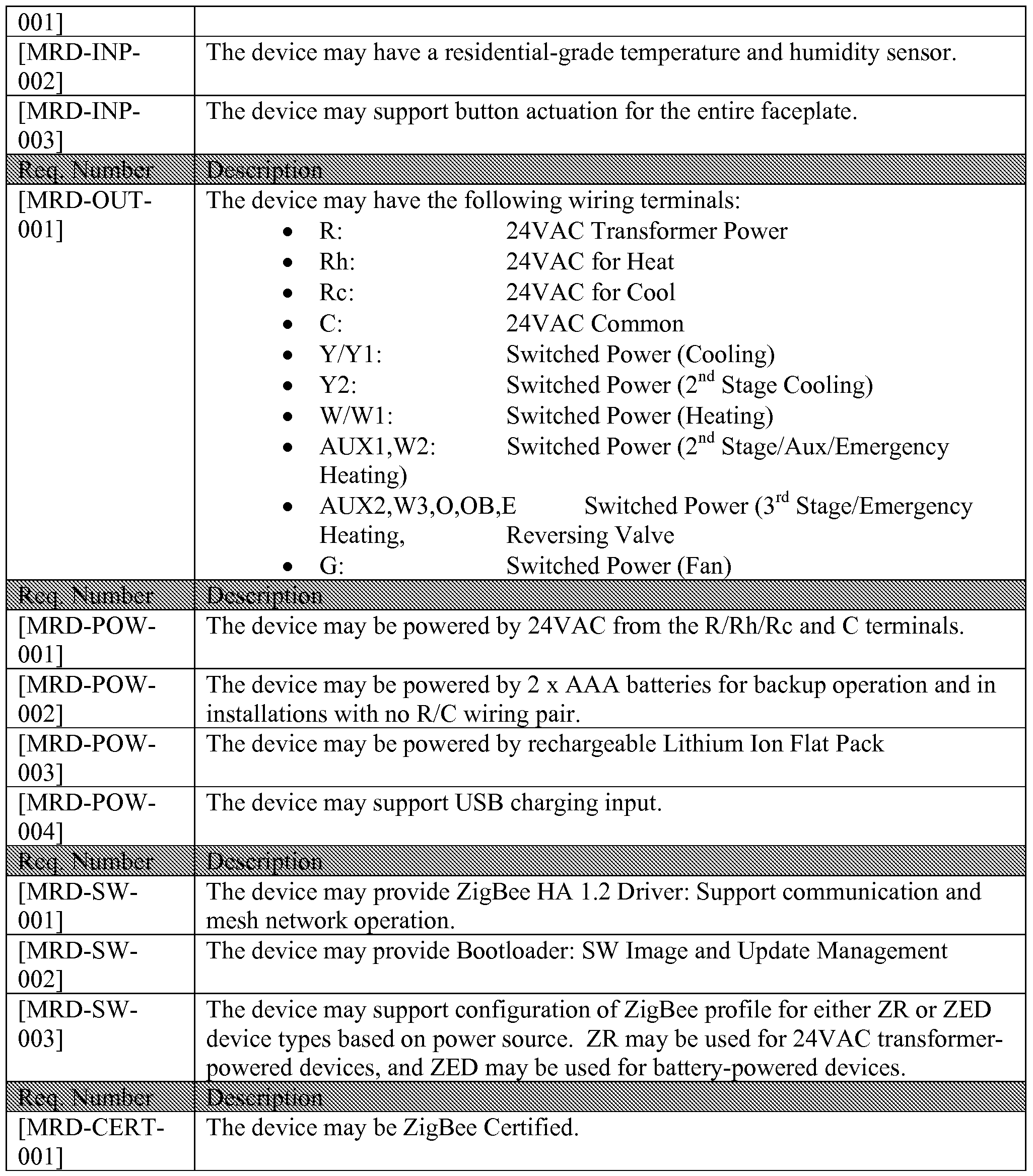
- the device may be ZigBee Certified.
- the device may be ZigBee Certified.
- Those skilled in the art will understand that the listed components and materials, and the specific configuration depicted, are intended to be exemplary only, and that other configurations, components, and materials may be used without departing from the scope of the disclosure. More generally, while certain exemplary aspects and embodiments have been described herein, many alternatives, modifications, and variations will be apparent to those skilled in the art. Accordingly, exemplary aspects and embodiments set forth herein are intended to be illustrative, not limiting. Various modifications may be made without departing from the spirit and scope of the disclosure.
Abstract
An exemplary aspect comprises a temperature control apparatus comprising: (a) a microprocessor in communication with an HVAC control system; (b) a wireless transceiver in communication with the microprocessor and with a controller operable to communicate over a wireless network with an application on a mobile device; (c) a temperature sensor in communication with the microprocessor; and (d) a front panel that allows a user to interface with the controller.
Description
ENVIRONMENTAL CONTROL APPARATUS AND RELATED METHODS
Cross-reference to Related Applications
This application claims priority to U.S. Provisional Pat. App. No. 61/969,725, filed March 24, 2014, entitled "Control Apparatus and Related Methods." The entire contents of that application, including the appendices, are incorporated herein by reference.
Introduction
One or more exemplary embodiments described herein comprise a thermostat apparatus in communication with one or more remote environmental sensors.
Using the remote sensors, which may detect presence of room occupants, the apparatus may raise or lower temperature in a particular room (or zone), for example, based on whether that room is currently occupied. The apparatus further may allow multiple zones to work in conjunction, instead of treating each zone separately.
An exemplary aspect comprises a temperature control apparatus comprising: (a) microprocessor in communication with an HVAC control system; (b) a wireless transceiver in communication with the microprocessor and with a controller operable to communicate over a wireless network with an application on a mobile device; (c) a temperature sensor in communication with the microprocessor; and (d) a front panel that allows a user to interface with the controller.
In one or more exemplary embodiments: (1) the wireless transceiver is in communication with the controller is a ZigBee transceiver; (2) the microprocessor is programmed by a user to perform one or more actions; (3) the temperature control apparatus further comprises an accelerometer; (4) the accelerometer is operable to allow the microprocessor detect tapping by a user on the front panel; and (5) the microprocessor is programmed so that a set number of taps by a user on the front panel results in a predetermined change in temperature settings.
The above and other features of exemplary aspects and embodiments will be apparent from the drawings and detailed description provided herein.
Brief Description of the Drawings
FIG. 1 depicts a configuration of an exemplary embodiment.
FIG. 2 depicts an exemplary face plate of an embodiment.
FIG. 3 depicts exemplary app screens of an embodiment.
FIG. 4 depicts a controller that may be used with an exemplary embodiment.
FIG. 5 depicts exemplary app screens for a controller that may be used with an exemplary embodiment.
Detailed Description of Certain Exemplary Embodiments
A configuration of an exemplary embodiment is depicted in FIG. 1.
AC to DC Converter
This power converter may step down the 24V AC provided from the heating/cooling power lines to the correct DC voltage needed to run the apparatus and keep the backup battery charged and on standby.
Temperature and Humidity Sensor
The temperature and humidity sensor allows the apparatus to serve as an additional sensing zone. This data can not only be used in heating and cooling the home but also can be used to drive other aspects of the smart home.
HVAC 24V Control Signal Emulation or Switching
This is the control center of the apparatus. This solution may route 24v via relays or emulation to the appropriate relays on the HVAC system. Those skilled in the art may appreciate that cost and efficiency may be the driver on selecting specific Relays or Emulation for signaling the 24V HVAC Control relays. 24V applied to Yl, for example, may turn on the Cooling system.
Wire Terminals
Wire terminals allow the installation process to be quick and easy. Wires from the HVAC system are connected to the corresponding terminals by inserting wires in to the corresponding holes. This type of connector allows for easy insertion and removal of wires should the need arise.
Backup Battery (Example: Rechargable Lithium ion CR2450 3.6v, or Lithium ion flat pack)
This battery may be charged by the converted 24V AC coming in off of the HVAC system and may stand in should voltage not be adequate enough to run apparatus. Those skilled in the art will appreciate that any suitable batteries or other power source may be used instead of Lithium ion batteries.
Zigbee Module (Example: Silicon Labs: EM357 Ember)
Using a Zigbee module for communication between The apparatus and external control devices, such as a controller, hub, or an app interface, allows for easy exchange of data and control. The module also acts as a passive extender for other Zigbee modules allowing the overall Zigbee network to increase in coverage area.
TABLE 1: Exemplary Wiring and Pinout
Symbol Name / Description Color
RH 24V Heat Load Red
RC 24V Cooling Load Red
C Common Ground Blue
Yl Cool Control Relay Yellow
(Jump to RC to turn on Cool)
Y2 Stage 2 Cooling Relay Yellow/Purple/White
Wl Heat Control Relay White
(Jump to RH to turn on
Heat),
O/OB Heat Pump Reversing Valve Orange
(Jump to RH to reverse)
G Fan Control Relay Green
(Jump to R to turn on Fan)
W2, Auxiliary Heat Stage 2 Heat Relay, Auxiliary White
Heat Relay
W3, E, Stage 3 Heat Relay, White
Humidifier/Dehumidifier Emergency Heat Relay,
Humidifier/Dehumidifier
Relay
Exemplary Design
The apparatus is designed to replace an existing thermostat, or in the case of new homes, be wired directly to an HVAC system, thus eliminating the need for expensive copper wiring.
The apparatus may comprise 2 parts: (1) a wiring plate, which gets mounted to the wall and has terminals to accept the wires which control the HVAC system, as well as the front face; and (2) a face plate, which houses the electronic components and is the consumer side of the product. See FIG. 2.
An exemplary embodiment is currently sold as the "Wink Norm", by Wink Inc., and is described at http://www.wink.com/products/quirkyge-norm-thermostat/.
The faceplate of the apparatus, once wired up, attaches directly to the wiring plate, concealing the wires behind.
Exemplary Installation:
Physical Installation:
1. Remove old thermostat faceplate from the wall.
2. Mark existing wires with their current positions using the included labels.
3. Dismount wires from old wall plate.
4. Remove old wallplate.
5. Pull wires through base plate and mount the plate using included drywall screws.
6. Match each wire to its corresponding wire terminal and insert wire.
7. Snap faceplate onto the base.
Setting up from a Controller
A multi-device controller such as that described in co-pending U.S. Pat. app. no. 14/667,127, entitled "CONTROL APPARATUS AND RELATED METHODS", may be used with one or embodiments. More details on such a controller are provided below in the Exemplary Controller section.
From any control screen on the Controller, tap on settings.
1. Tap Devices and you should see a list of all registered devices on top and newly discovered devices below.
2. Locate the new apparatus in the bottom list and tap it.
3. Your Controller may register your new apparatus and add it to
your Wink account.
4. You are now able to interact with the apparatus from any
Controller or device running the Wink app.
In-App User Interface
Controlling the apparatus (designated "Project 2" in FIG. 3) from within a Wink app preferably is simple and intuitive. Building off of the platform's ability to utilize the back end for creating schedules, the user may be presented with a simple interface to view and adjust temperature manually, as well as fine tune schedules.
The interface may allow for easy control of multiple zones by allowing the user to select which room they want to base temperature on, as well as which zone they are controlling in manual mode. The remote sensor for the thermostat may be the temperature and humidity sensor in the light switch (Controller) described above, and/or sensors in other products.
If a user has light switches in the dining room and bedroom, these would know the temperature in each room, and the thermostat may cool or heat more based on which room has priority. This priority also may be based on a user's location in the home (as determined by cell phone, motion detection, etc.). The thermostat itself also has a temperature and humidity sensor and thus may correspond to its own heating/cooling zone.
Scheduling may be a quick and painless activity for the user. The user may use a slider to select the room, temperature range, and time for this range to be active.
Historical usage data may also be available to the user from within the Interface.
In an embodiment, the device comprises an accelerometer, and the interface may be set up so that, for example, 1 tap = 4 degrees cooler (blue light) and 2 taps = 4 degrees warmer (red light). An RBG LED may be used to reflect the different colors.
Screen Descriptions (see FIG. 3)
Main Screen
The Main Screen may show basic information about the apparatus's current status. This may include the current temperature setting, ambient temperature in the heating/cooling zone the apparatus is installed in, and the current operation mode. If there are multiple apparatuses installed, the current temperatures of those may be included also. The home screen may also allow the user to toggle basic settings.
These may include the mode that the apparatus is in - either heating,
cooling, or fan only - and adjusting current temperature setting either hotter or colder.
Schedule
The Schedule screen offers a glimpse into how the HVAC system is going to be operated over the span of a specified time frame and allows a user to make adjustments based on preference or upcoming schedule.
Since the apparatus may be on the Wink ecosystem, and tied together with sensors throughout the home, a schedule may be
automatically created and adjusted in real time based on user habits and desired temperatures.
Add a new scheduled event:
1. Select Schedule from the Main Screen
2. Click the + icon to add a new event which brings up the Event Detail Modal screen.
3. Adjust the desired day and time the event should occur and if it should recur.
4. Set the desired temperature set point for that time.
5. Close the Event Detail Modal. scheduled event:
1. Select Schedule from the Main Screen.
2. Tap on the scheduled event to edit which pulls up that event's Event Detail Modal.
3. Make adjustments to day/time or temperature.
4. Close the Event Detail Modal.
History
The History screen offers a glimpse into the user's heating and cooling usage. This information is easy to drill down by month / week / day and offers the user insight into how their schedules are being automatically created and the times at which their system is being most utilized.
Further exemplary details are provided in TABLE 2 below.
TABLE 2

Exemplary Controller
Settings Screen (see FIG. 5) User Settings
User Browser
The user browser allows a user to add, remove and edit users. Adding a user:
1. Enter the user browser from the settings screen.
2. Click the + sign to add a new user.
3. Controller displays BLE (Bluetooth Low Energy) devices within range.
4. Select the proper device by clicking on it.
5. Controller prompts a user to create a username for a user profile.
6. Type in desired username and click OK.
7. Controller lands a user on User Preference Screen to begin setting user preferences.
Adding a user will display a modal view which searches for BLE compatible devices in the area.
Once the desired device is located, and selected, a user name is requested. User Preferences
User Preferences allows a user to set up a Controller the way a user likes it, with the user's own Wink account, the user's own devices and the user's own Dashboard layouts.
User Preferences may contain three sections (Dashboard, Devices, and Change Wink Account).
Setting Dashboard Preferences
1. Choose which "widgets" a user would like to use, in addition to the defaults, by checking the box next to each item the user would like displayed. a. Any widget with further customization should include a settings icon that displays a modal for setting up that additional configuration (adding a user's twitter account, for example).
2. Choose Celsius / Fahrenheit for temperature displays.
Device Settings
Room Settings Room Name Light Load Settings
Load Name (Front High Hats, Track Lighting)
Load type (Standard Light/ Fan/ Smart Bulbs)
Device List
A list of devices may be assigned to a user's account and made available for the user to control.
Any device controllable with On/Off triggers can be grouped together to be controlled together with a single action.
Each device and group can be assigned to a physical button and displayed or hidden in an "Alternate Device Callout" with a check box.
Change Account
This button allows a user to disassociate a user profile with account and sign into another.
Local Control Screen
When operating locally, the 1 or 2 connected loads may be the main focus of the screen. There may be an interface for switching these two off and on with extreme ease (single tap on/off).
Below this main interaction point may be listed additional devices that have been assigned by the user. They may only load items in the list that are
pertinent to the present room, but the experience may be freeform (see "Alternate Device Callout" below).
Remote Control Screen (access a different room)
1. Bring up a Room Switching Modal with a tap of the room icon.
2. Select the room to work with.
3. This screen may be a duplicate of the Local Control Screen for that room.
4. This may reset after x number of seconds so that someone doesn't enter the room and control the wrong room. The user may not have to hit a "back button."
Alternate Device Callout
Additional devices may be selected by the user to appear in the bottom of the control screen. A scrollable marquee may be located toward the bottom of the screen. A user may slide these until locating the device a user would like to control and selecting it with a tap. When the device is selected it loads the interaction screen for that device. (WAC, Pivot Power, Etc...)
The last icon in this list may be a "+" to add more devices. This may load a user's existing Wink account device list and provide the ability to add more devices via discovered Zigbee (IEEE 802.15.4) devices as well as Wifi devices, depending on how each is configured.
Room Switching Modal
Simple modal view showing all of the connected Controllers and listing them by name. These connections may be established registered devices as well as unregistered devices seen on BLE and displayed as "New Controller" or "Unregistered Controller" and listed in a sub category below as "Newly
Discovered".
Controlling Different Rooms
• Select Change Rooms Icon from any control screen.
• Select which room a user would like to switch to and tap it.
• Begin controlling this room as if it was local.
Discovering new products
Whenever a new Controller is installed it will automatically show up under Device settings / Devices
• From Load Control Screen select "Settings"
• Select Device Settings / Devices
• All registered Controller devices are listed on top and can be configured by clicking on them.
• All unregistered Controller devices are listed below under "Discovered Devices"
• Click any of these devices to register it.
• Give the new Controller a name.
Permissions allow a user to specify who can access what and when.
Controlling Other Connected Products
Scroll through the list of available products at the bottom of the load control screen.
Tap on the product a user would like to control.
Interact with the product via its own custom page view.
Controlling Different Rooms
• Select Change Rooms Icon from any control screen.
• Select which room a user would like to switch to and tap it.
Begin controlling this room as if it was local.
Whenever a new Controller is installed it will automatically show up under Device settings / Devices
• From Load Control Screen select "Settings"
• Select Device Settings / Devices
• All registered Controller devices are listed on top and can be configured by clicking on them.
• All unregistered Controller devices are listed below under "Discovered Devices"
• Click any of these devices to register it.
• Give the new Controller a name.
Permissions allow a user to specify who can access what and when.
Exemplary Construction and Components (see FIG. 4) TABLE 3
Description Manufacturer Manufacturer Part Number I i Central Processor - Host : Freescale ; Ϊ.ΜΧ6
1 WiFi 802.1 1 a/b/g/n and : Semco/Samsung \ BCM4334 Based i Bluetooth Module ; Semco SWB-B53 Module i Zigbee : Silicon Labs ; EM357 SoC
DDR3 - Host : Micron ; VH'4 1 K256V1 1 61 Ι Λ- 1 25 : 1 ·:
1 NAND FLASH - Host : Micron ; MT29F16G08MAAWP
j Serial NOR FLASH
j DC-DC PMIC : Freescale : MMPF0100F0ZES i Proximity Sensor
i Temperature & Humidity
i Sensors
i Audio Codec : Wolfson ; WM8962
i Microphone
i Speaker
j LEDs
j AC-DC Power Supply
j Unit
j TFT-LCD Display
i Capacitive Touch Panel
i Wireless Antennas
PCB
Central Processor - Host (Freescale i.MX6)
This board allows the system to run Android as the underlying OS and launch a custom build of the wink app. This app may be catered to this application but allow for the addition of all products compatible with the wink ecosystem.
System Memory - Host
DDR3 512M x 64
NAND Flash 2GB
Serial NOR FLash 4MB
4.3" Capacitive Multi-Touch Screen [MRD-DISP-001]
The central interaction point of the product, the touch screen is where most of the interaction happens. With a personalized dashboard as a user default, a quick touch switches to the switch screen, allowing control of the local loads the switch replaced, as well as any other components.
Bluetooth / WIFI Combo Chip (Semco SWB-B53 based on Broadcom
BCM4334)
[MRD-SW-002]
Not only providing the connectivity of the unit, this chip allows for Bluetooth and BLE connectivity which opens up an entire new spectrum of products the Wink platform can take advantage of.
Bluetooth, while as stated, allows control of other products, it may also allow other Bluetooth devices to control the light switch.
BLE allows the system to serve custom experiences based on
who is standing at the panel, as their phone will be recognized.
The WIFI capability provides for connectivity to the Internet via a local router.
Zigbee Module (Silicon Images EM357 Ember)
[MRD-SW-003]
The use of Zigbee enables support for existing products such as wireless light bulbs (Philips Hue, etc.) as well as development of future products. The use of Zigbee also acts as a passive extender for other Zigbee products the user may already own, thus increasing the range in which their existing products work with each other.
2 x Momentary Switches
These switches can control the local loads on them (the lights a user switches were tied to) and also can be configured to control virtually any smart product that reacts to on/off etc. (Garage Door, Smart light bulbs located anywhere [and not just one], Pivot Power Genius). The satisfying click lets a user know the button was pressed and is a quick way to interact with a user's home without having to interact with the screen if a user is on the go.
Motion/Prox Sensor
[MRD-INP-001]
The IR Sensor is how the switch knows a user is coming up to interact. This gives the switch time to wake up and provide a user with the info or control a user needs immediately without a user having to waste time waking the unit up. Those skilled in the art will appreciate that any suitable motion or position sensor may be used instead of an IR sensor.
2 x Solid State AC Relays
The A/C Relays are switches. The switch is wired to replace 1 or 2 switches with the same SKU. The Relay, when given the signal, switches the local loads on and off. This signal can come from the local buttons, the touch screen, or any other device running the wink app.
AC/DC Converter
The converter may be how the apparatus is powered. The AC power from the gang box is converted to DC.
Temperature & Humidity Sensor
With the inclusion of temp and humidity sensors, a user has more data about their home at their fingertips.
Microphone
[MRD-INP-003]
The microphone gives control opportunity as well as the ability to incorporate an internal intercom system. Voice commands may be used, and other sounds may be recognized (doors opening/closing, dogs barking, etc.).
Speaker
[MRD-OUT-001]
As with the microphone, the speaker may allow for intercom operability as well as give the device a personality and voice, as well as reminders and audible alerts.
Further technical details of one or more exemplary embodiments are provided below.
Exemplary Structure
An exemplary embodiment may comprise:
Main Board with Central Processer, Memories, PMIC, WiFi/Bluetooth SIP Module, Zigbee, Temp & Humidity Sensors, Microphone, Speaker,
Connectors, Buttons
TFT-LCD Display Module with Capacitive Touch and Protection Lens
AC-Relay Unit
AC-DC Power Supply Unit with Connectors
Mechanical Assembly Parts
Hardware Reset Button
Internal Antennas for WiFi/BT and Zigbee
Cable/connectors for signal Interfaces and Power connections
The device may support two mechanical buttons for controlling either local or remote loads; S/W configurable via GPIO
The device may attempt to fit into a North American single gang and double gang wall receptacle
Exemplary Installation Method
The device may provide three positions for the power box to be placed - to right, center, or to left.
A. Exemplary Hardware Functional Block Diagram
The block diagram depicted in FIG. 4 shows exemplary high level architecture of the controller and power box.
Exemplary Central Processor - Host
The device may use a Freescale i.MX6 family processor supporting Android OS framework. [PR-001 ] (PR citations refer to TABLE 2 below).
Exemplary System Memory - Host
The device may support the following system memory [PR-002] :
DDR3 512M x 64
NAND FLASH 2GB
Serial NOR FLASH 4MB Exemplary WiFi/Bluetooth [MRD-COM-001] [MRD-COM-002]
Semco SWB-B53 module based on Broadcom BCM4334 may be used to support IEEE 802.11 g/n and Bluetooth 4.0 LE. [PR-003]
The testing and qualification of the device may be based on 802.11 g and n. [PR-
004]
· The device may use the 2.4 GHz frequency band for 802.11 n. [PR-005]
The device may support both 20MHz and 40MHz bandwidth at IEEE 802.1 In. [PR-
006]
The lightswitch may support Bluetooth 4.0 LE. [PR-007]
The WiFi Bluetooth coexistence may be handled by the SWB-B53 module. [PR- 008]
The device may have one antenna that is shared between WiFi and Bluetooth. [PR-
009]
Exemplary Zigbee Functionality [MRD-COM-003] [MRD-SW-003]
The Zigbee functionality may be supported using Silicon Images EM357 Ember® ZigBee chip. [PR-010]
The device may support the coexistence of Zigbee with WiFi and BT since both the technologies use 2.4 GHz ISM band. [PR-011]
The device may support Zigbee mesh networking capability. [PR-012]
Exemplary TFT-LCD Module with Touch [MRD-DISP-001]
The device may use a 4.3 inch or other TFT-LCD display panel. [PR-013]
Exemplary Motion/Proximity Sensor [MRD-INP-001]
The device may have a built-in motion or proximity detection sensor to allow a user to wake up the display by, for example, waving hands 10 cm in front of display screen. [PR-014a]
The device may allow a detectable range of 4 to 5 ft with minimal latency. [PR- 014b]
Exemplary Temperature and Humidity Sensors
The device may have sensor(s) to enable the Smart Light Switch to collect room temperature and humidity information. [PR-015]
Exemplary Microphone and Speaker [MRD-INP-003] [MRD-OUT-001]
The analog microphone and speaker may be interfaced with the Audio codec to the Ϊ.ΜΧ6 processor to provide intercom and voice notification feature. [PR-016]
Exemplary AC-Relay Switch
The AC relay switch may fit in the power box [PR-017]
Exemplary AC-DC Power Supply Unit
The AC-DC PSU may operate at AC input between lOOVAC to 240V AC

The AC -DC PSU may fit in the power box [PR-019]
Exemplary Mechanical Design
External Specifications
User I/O Interfaces
Touch Screen
Push Buttons x 2
LED Indicator x 2
Hardware Reset Button x 2
Speaker x 1
Microphone x 1
Motion Sensor x 1
Temperature & Humidity Sensor(s)
Single/Double Gangbox Real Estate
The device may fit inside, cover, and mechanically affix to both North American single-gang and double-gang wall receptacles. [PR-020]
Exemplary Single Gangbox - may have dimensions:
Width: 50mm, for example.
Height: 87mm, for example.
Depth: 60mm, for example.
Exemplary Double Gangbox - may have dimensions:
Width: 94mm, for example.
Height: 95mm, for example.
Depth: 70mm, for example.
The power box and device may follow the NEMA code.
Mechanical Buttons
The single gang box design may have two mechanical switches supporting following requirements [PR-021]:
The device itself may have the two buttons to the right and programmable to control either the local load or other functions within the home.
The device may have terminals for 2 loads; in a single-gang configuration, one may be empty.
The single gangbox design with two switches is the nominal case. The nominal design may provide expandability support for the 3- and 4-gang plates.
The mechanical button may, for example, have a feel similar to Omron's B3F-4005 tactile switch.
The operating force may be, for example, 260g.
The size of the switch may be, for example, 12.5 mm x 12.5 mm. The dome of the switch may be, for example, 8.4 mm in diameter.
Summary of Exemplary Technical Specifications (TABLE 4)

PR-014b The device may allow a detectable range of 4 to 5 ft with minimal latency.
PR-015 The device may have sensor(s) to enable the Smart Light
Switch to collect room temperature and humidity information.
PR-016 The analog microphone and speaker may be interfaced with the Audio codec to the i.MX6 processor to provide intercom and voice notification feature.
PR-017 The AC relay switch may fit in the power box
PR-018 The AC-DC PSU may operate at AC input between
lOOVAC to 240VAC 50/60Hz
PR-019 The AC-DC PSU may fit in the power box
PR-020 The device may fit inside, cover, and mechanically affix to both North American single-gang and double-gang wall receptacles.
PR-021 The single gang box design may have two mechanical switches supporting requirements in Section 3.4.6
PR-022 The 802.11 g/n may support minimum data rate of 0.25
Mbps
PR-023 The device may comply with the environmental
requirements as described in Section 5.1
PR-024 The device may comply with the reliability requirements as described in Section 5.2.
PR-025 The device may comply with the regulatory compliance requirements to place the product in the US market.
PR-026 The device may comply with the regulatory compliance requirements to place the product in the Canadian market.
PR-027 The device may be ZigBee Certified.
Those skilled in the art will understand that the listed components and materials, and the specific configuration depicted, are intended to be exemplary only, and that other configurations, components, and materials may be used without departing from the scope of the disclosure. More generally, while certain exemplary aspects and embodiments have been described herein, many alternatives, modifications, and variations will be apparent to those skilled in the art. Accordingly, exemplary aspects and embodiments set forth herein are intended to be illustrative, not limiting. Various modifications may be made without departing from the spirit and scope of the disclosure.
Claims
1. A temperature control apparatus comprising:
a microprocessor in communication with an HVAC control system;
a wireless transceiver in communication with said microprocessor and with a controller operable to communicate over a wireless network with an application on a mobile device;
a temperature sensor in communication with said microprocessor; and a front panel that allows a user to interface with said controller.
2. A temperature control apparatus as in claim 1, wherein said wireless transceiver is in communication with said controller is a ZigBee transceiver.
3. A temperature control apparatus as in claim 1, wherein said
microprocessor is programmed by a user to perform one or more actions.
4. A temperature control apparatus as in claim 1, further comprising an accelerometer.
5. A temperature control apparatus as in claim 4, wherein said accelerometer is operable to allow said microprocessor detect tapping by a user on said front panel.
6. A temperature control apparatus as in claim 5, wherein said
microprocessor is programmed so that a set number of taps by a user on said front panel results in a predetermined change in temperature settings.
Priority Applications (2)
| Application Number | Priority Date | Filing Date | Title |
|---|---|---|---|
| EP15769546.1A EP3123264A4 (en) | 2014-03-24 | 2015-03-24 | Environmental control apparatus and related methods |
| CN201580023453.9A CN106537051A (en) | 2014-03-24 | 2015-03-24 | Environmental control apparatus and related methods |
Applications Claiming Priority (2)
| Application Number | Priority Date | Filing Date | Title |
|---|---|---|---|
| US201461969725P | 2014-03-24 | 2014-03-24 | |
| US61/969,725 | 2014-03-24 |
Publications (1)
| Publication Number | Publication Date |
|---|---|
| WO2015148511A1 true WO2015148511A1 (en) | 2015-10-01 |
Family
ID=54141751
Family Applications (2)
| Application Number | Title | Priority Date | Filing Date |
|---|---|---|---|
| PCT/US2015/022255 WO2015148511A1 (en) | 2014-03-24 | 2015-03-24 | Environmental control apparatus and related methods |
| PCT/US2015/022247 WO2015148505A1 (en) | 2014-03-24 | 2015-03-24 | Control apparatus and related methods |
Family Applications After (1)
| Application Number | Title | Priority Date | Filing Date |
|---|---|---|---|
| PCT/US2015/022247 WO2015148505A1 (en) | 2014-03-24 | 2015-03-24 | Control apparatus and related methods |
Country Status (4)
| Country | Link |
|---|---|
| US (2) | US9501051B2 (en) |
| EP (2) | EP3123264A4 (en) |
| CN (2) | CN106537051A (en) |
| WO (2) | WO2015148511A1 (en) |
Families Citing this family (16)
| Publication number | Priority date | Publication date | Assignee | Title |
|---|---|---|---|---|
| US9967151B2 (en) * | 2014-02-18 | 2018-05-08 | David R. Hall | Secure remote actuation system |
| USD763882S1 (en) * | 2014-04-25 | 2016-08-16 | Tencent Technology (Shenzhen) Company Limited | Portion of a display screen with animated graphical user interface |
| USD864879S1 (en) * | 2014-07-22 | 2019-10-29 | Levven Automation Inc. | Light switch |
| USD809407S1 (en) * | 2015-01-09 | 2018-02-06 | Broan-Nutone Llc | Humidity wall control |
| US10741345B2 (en) | 2015-01-09 | 2020-08-11 | Broan-Nutone Llc | Humidity wall control |
| US10057965B2 (en) | 2015-05-04 | 2018-08-21 | Fulham Company Limited | LED driver and lighting systems technologies |
| ITUB20159599A1 (en) | 2015-12-28 | 2017-06-28 | Beghelli Spa | CONTROL DEVICE FOR ELECTRIC CONTROL UNITS |
| JP6453782B2 (en) * | 2016-01-08 | 2019-01-16 | ミネベアミツミ株式会社 | Planar switch and planar switch unit |
| US10143066B2 (en) | 2016-02-23 | 2018-11-27 | MW McWong International, Inc. | Sensor with wireless device for controlling a light source |
| US10592084B2 (en) | 2016-12-09 | 2020-03-17 | Johnson Controls Technology Company | Tools, systems and methods for configuring a building management system |
| US10726835B2 (en) * | 2016-12-23 | 2020-07-28 | Amazon Technologies, Inc. | Voice activated modular controller |
| CN107517534A (en) * | 2017-08-19 | 2017-12-26 | 合肥智贤智能化科技有限公司 | A kind of intelligent-induction formula ight lamp |
| GB2586209B (en) * | 2019-07-23 | 2022-06-15 | Ian Brough Darron | An environment sensing apparatus |
| WO2022077263A1 (en) * | 2020-10-14 | 2022-04-21 | Honeywell International Inc. | Building controller with antenna |
| CN115167162A (en) * | 2022-06-27 | 2022-10-11 | 青岛海尔科技有限公司 | Visiting information reminding method and system |
| WO2024026543A1 (en) * | 2022-08-05 | 2024-02-08 | Berlitz Participações Societárias Ltda | Smart brightness control device and management method |
Citations (6)
| Publication number | Priority date | Publication date | Assignee | Title |
|---|---|---|---|---|
| US20080033599A1 (en) * | 2006-08-02 | 2008-02-07 | Rouzbeh Aminpour | Method and system for controlling heating ventilation and air conditioning (HVAC) units |
| WO2009124217A1 (en) * | 2008-04-02 | 2009-10-08 | Genea Energy Partners, Inc. | Building optimization system and lighting switch with adaptive blind, window and air quality controls |
| US7831338B1 (en) * | 2007-01-23 | 2010-11-09 | Steven Haydu | Electronically zoned remote actuated device |
| US20110125328A1 (en) * | 2009-11-24 | 2011-05-26 | Friedrich Air Conditioning Co., A Division Of U.S. Natural Resources, Inc. | Control System for a Room Air Conditioner and/or Heat Pump |
| US20130181927A1 (en) * | 2006-09-13 | 2013-07-18 | Savant Systems, Llc | Remote control unit for a programmable multimedia controller |
| US20130221117A1 (en) * | 2010-11-19 | 2013-08-29 | Nest Labs, Inc. | Power management in single circuit hvac systems and in multiple circuit hvac systems |
Family Cites Families (23)
| Publication number | Priority date | Publication date | Assignee | Title |
|---|---|---|---|---|
| US6934862B2 (en) * | 2000-01-07 | 2005-08-23 | Robertshaw Controls Company | Appliance retrofit monitoring device with a memory storing an electronic signature |
| EP1394549A1 (en) * | 2002-08-23 | 2004-03-03 | Bayer HealthCare AG | Biomarkers for diagnosing Alzheimer's disease |
| BR0303797C1 (en) * | 2003-09-05 | 2004-11-03 | Daihatsu Ind E Com De Moveis E | Improvement introduced in manual electric hair straightening equipment |
| US7913925B2 (en) * | 2004-07-23 | 2011-03-29 | Ranco Incorporated Of Delaware | Color changing thermostatic controller |
| DE102005016684A1 (en) * | 2005-04-11 | 2006-10-12 | Deutsche Thomson-Brandt Gmbh | Memory arrangement, in particular for the non-volatile storage of uncompressed video and / or audio data |
| CN101938389A (en) * | 2005-09-30 | 2011-01-05 | 皇家飞利浦电子股份有限公司 | Wireless building automation and Control Network, digital ballast and wireless control apparatus |
| US9338839B2 (en) * | 2006-03-28 | 2016-05-10 | Wireless Environment, Llc | Off-grid LED power failure lights |
| US8199005B2 (en) * | 2007-11-06 | 2012-06-12 | Honeywell International Inc. | System and methods for using a wireless sensor in conjunction with a host controller |
| US7900849B2 (en) * | 2007-11-30 | 2011-03-08 | Honeywell International Inc. | HVAC remote control unit and methods of operation |
| GB2473581B (en) * | 2008-07-07 | 2013-04-24 | Control4 Corp | Systems and methods for presenting power saving opportunities for electronic devices |
| US20110016739A1 (en) * | 2009-05-06 | 2011-01-27 | Bescorp. Inc. | Multi-directional conveyor and method |
| US8432368B2 (en) * | 2010-01-06 | 2013-04-30 | Qualcomm Incorporated | User interface methods and systems for providing force-sensitive input |
| CN102893327B (en) * | 2010-03-19 | 2015-05-27 | 数字标记公司 | Intuitive computing methods and systems |
| US9520056B2 (en) * | 2010-05-11 | 2016-12-13 | Universal Electronics Inc. | System and methods for enhanced remote control functionality |
| US20120031984A1 (en) * | 2010-08-03 | 2012-02-09 | Massachusetts Institute Of Technology | Personalized Building Comfort Control |
| US8918219B2 (en) * | 2010-11-19 | 2014-12-23 | Google Inc. | User friendly interface for control unit |
| US8665210B2 (en) * | 2010-12-22 | 2014-03-04 | Microsoft Corporation | Sensing user input using the body as an antenna |
| US9230708B2 (en) * | 2011-01-17 | 2016-01-05 | Jawaharlal Nehru Centre For Advanced Scientific Research | Self assembly of naphthalene diimide derivatives and process thereof |
| WO2013011337A1 (en) | 2011-07-15 | 2013-01-24 | Nokia Corporation | Method and apparatus for distributing sensor data |
| US9215779B2 (en) * | 2012-03-30 | 2015-12-15 | Cooper Technologies Company | Light switch and control device having a touch screen interface |
| US20140062340A1 (en) * | 2012-08-31 | 2014-03-06 | Ahmed Elgayyar | Electrical Switch Device with Automatic Control |
| US9198259B2 (en) * | 2013-02-27 | 2015-11-24 | Nguyen Hoan Hoang | Programmable touchscreen dimmer with interchangeable electronic faceplate |
| US9014686B2 (en) * | 2013-05-06 | 2015-04-21 | Emerson Electric Co. | Provisioning a wireless-capable device for a wireless network |
-
2015
- 2015-03-24 EP EP15769546.1A patent/EP3123264A4/en not_active Withdrawn
- 2015-03-24 WO PCT/US2015/022255 patent/WO2015148511A1/en active Application Filing
- 2015-03-24 CN CN201580023453.9A patent/CN106537051A/en active Pending
- 2015-03-24 WO PCT/US2015/022247 patent/WO2015148505A1/en active Application Filing
- 2015-03-24 US US14/667,127 patent/US9501051B2/en active Active
- 2015-03-24 CN CN201580027147.2A patent/CN106664772A/en active Pending
- 2015-03-24 US US14/667,182 patent/US20150267936A1/en not_active Abandoned
- 2015-03-24 EP EP15770381.0A patent/EP3123839A4/en not_active Withdrawn
Patent Citations (6)
| Publication number | Priority date | Publication date | Assignee | Title |
|---|---|---|---|---|
| US20080033599A1 (en) * | 2006-08-02 | 2008-02-07 | Rouzbeh Aminpour | Method and system for controlling heating ventilation and air conditioning (HVAC) units |
| US20130181927A1 (en) * | 2006-09-13 | 2013-07-18 | Savant Systems, Llc | Remote control unit for a programmable multimedia controller |
| US7831338B1 (en) * | 2007-01-23 | 2010-11-09 | Steven Haydu | Electronically zoned remote actuated device |
| WO2009124217A1 (en) * | 2008-04-02 | 2009-10-08 | Genea Energy Partners, Inc. | Building optimization system and lighting switch with adaptive blind, window and air quality controls |
| US20110125328A1 (en) * | 2009-11-24 | 2011-05-26 | Friedrich Air Conditioning Co., A Division Of U.S. Natural Resources, Inc. | Control System for a Room Air Conditioner and/or Heat Pump |
| US20130221117A1 (en) * | 2010-11-19 | 2013-08-29 | Nest Labs, Inc. | Power management in single circuit hvac systems and in multiple circuit hvac systems |
Non-Patent Citations (1)
| Title |
|---|
| See also references of EP3123264A4 * |
Also Published As
| Publication number | Publication date |
|---|---|
| EP3123264A4 (en) | 2017-11-15 |
| EP3123839A4 (en) | 2017-11-15 |
| EP3123839A1 (en) | 2017-02-01 |
| US20150267936A1 (en) | 2015-09-24 |
| CN106664772A (en) | 2017-05-10 |
| EP3123264A1 (en) | 2017-02-01 |
| US20150271900A1 (en) | 2015-09-24 |
| CN106537051A (en) | 2017-03-22 |
| WO2015148505A1 (en) | 2015-10-01 |
| US9501051B2 (en) | 2016-11-22 |
Similar Documents
| Publication | Publication Date | Title |
|---|---|---|
| US20150267936A1 (en) | Environmental control apparatus and related methods | |
| ES2724952T3 (en) | Autonomous wireless lighting application | |
| US10009988B2 (en) | Load control adjustment from a wireless device | |
| EP3070557B1 (en) | Smart home scenario switching method and system | |
| ES2714222T3 (en) | Procedure and apparatus for creating and modifying graphic programming | |
| CN105431891B (en) | lighting controller | |
| US20190042000A1 (en) | Smart switch | |
| US8897897B2 (en) | Companion control interface for smart devices | |
| US10693993B2 (en) | Building services control | |
| US20130211844A1 (en) | Solar Powered Portable Control Panel | |
| CN107942715A (en) | Intelligent control panel and its control method and control device | |
| US20190087076A1 (en) | Using a wireless mobile device and photographic image of a building space to commission and operate devices servicing the building space | |
| US8914724B2 (en) | Method and apparatus for creating and modifying graphical schedules | |
| CN111781849A (en) | Energy management system, energy management controller, energy management method, and recording medium | |
| EP3026873A1 (en) | Electronic smart device holder | |
| JP2015025616A (en) | Air conditioner | |
| EP3258326A1 (en) | Automated control system for homes | |
| CA3104907C (en) | Retrofit smart home controller device with power supply module, charger and dock | |
| JP2006304078A (en) | Separate setting remote control system and electronic apparatus equipped therewith | |
| US20210302048A1 (en) | Zoning devices and system | |
| KR20130083503A (en) | Method of electric power control using wirelessly-connected switch or outlet and smart media device | |
| AU2017203428B2 (en) | A Non-Essential Circuit Switch System | |
| KR20170062360A (en) | Terminal, apparatus and system for controlling local service | |
| KR20170012127A (en) | Smart switch provided in wall of room of a building for illumination light | |
| NZ616350B2 (en) | Method and apparatus for creating and modifying graphical schedules |
Legal Events
| Date | Code | Title | Description |
|---|---|---|---|
| NENP | Non-entry into the national phase |
Ref country code: DE |
|
| REEP | Request for entry into the european phase |
Ref document number: 2015769546 Country of ref document: EP |
|
| WWE | Wipo information: entry into national phase |
Ref document number: 2015769546 Country of ref document: EP |
|
| 121 | Ep: the epo has been informed by wipo that ep was designated in this application |
Ref document number: 15769546 Country of ref document: EP Kind code of ref document: A1 |