WO2015036068A1 - Method for the provision and transmission of data, in particular with a link to a vehicle - Google Patents
Method for the provision and transmission of data, in particular with a link to a vehicle Download PDFInfo
- Publication number
- WO2015036068A1 WO2015036068A1 PCT/EP2014/001889 EP2014001889W WO2015036068A1 WO 2015036068 A1 WO2015036068 A1 WO 2015036068A1 EP 2014001889 W EP2014001889 W EP 2014001889W WO 2015036068 A1 WO2015036068 A1 WO 2015036068A1
- Authority
- WO
- WIPO (PCT)
- Prior art keywords
- data
- sub
- control unit
- electronic control
- vehicle
- Prior art date
Links
Classifications
-
- H—ELECTRICITY
- H04—ELECTRIC COMMUNICATION TECHNIQUE
- H04L—TRANSMISSION OF DIGITAL INFORMATION, e.g. TELEGRAPHIC COMMUNICATION
- H04L12/00—Data switching networks
- H04L12/28—Data switching networks characterised by path configuration, e.g. LAN [Local Area Networks] or WAN [Wide Area Networks]
- H04L12/40—Bus networks
- H04L12/40169—Flexible bus arrangements
-
- H—ELECTRICITY
- H04—ELECTRIC COMMUNICATION TECHNIQUE
- H04L—TRANSMISSION OF DIGITAL INFORMATION, e.g. TELEGRAPHIC COMMUNICATION
- H04L12/00—Data switching networks
- H04L12/28—Data switching networks characterised by path configuration, e.g. LAN [Local Area Networks] or WAN [Wide Area Networks]
- H04L12/40—Bus networks
- H04L12/40006—Architecture of a communication node
- H04L12/40019—Details regarding a bus master
-
- H—ELECTRICITY
- H04—ELECTRIC COMMUNICATION TECHNIQUE
- H04L—TRANSMISSION OF DIGITAL INFORMATION, e.g. TELEGRAPHIC COMMUNICATION
- H04L12/00—Data switching networks
- H04L12/28—Data switching networks characterised by path configuration, e.g. LAN [Local Area Networks] or WAN [Wide Area Networks]
- H04L12/40—Bus networks
- H04L12/40143—Bus networks involving priority mechanisms
- H04L12/40156—Bus networks involving priority mechanisms by using dedicated slots associated with a priority level
-
- H—ELECTRICITY
- H04—ELECTRIC COMMUNICATION TECHNIQUE
- H04L—TRANSMISSION OF DIGITAL INFORMATION, e.g. TELEGRAPHIC COMMUNICATION
- H04L12/00—Data switching networks
- H04L12/28—Data switching networks characterised by path configuration, e.g. LAN [Local Area Networks] or WAN [Wide Area Networks]
- H04L12/46—Interconnection of networks
- H04L12/4604—LAN interconnection over a backbone network, e.g. Internet, Frame Relay
- H04L12/462—LAN interconnection over a bridge based backbone
- H04L12/4625—Single bridge functionality, e.g. connection of two networks over a single bridge
-
- H—ELECTRICITY
- H04—ELECTRIC COMMUNICATION TECHNIQUE
- H04L—TRANSMISSION OF DIGITAL INFORMATION, e.g. TELEGRAPHIC COMMUNICATION
- H04L12/00—Data switching networks
- H04L12/28—Data switching networks characterised by path configuration, e.g. LAN [Local Area Networks] or WAN [Wide Area Networks]
- H04L12/40—Bus networks
- H04L2012/40208—Bus networks characterized by the use of a particular bus standard
- H04L2012/40215—Controller Area Network CAN
-
- H—ELECTRICITY
- H04—ELECTRIC COMMUNICATION TECHNIQUE
- H04L—TRANSMISSION OF DIGITAL INFORMATION, e.g. TELEGRAPHIC COMMUNICATION
- H04L12/00—Data switching networks
- H04L12/28—Data switching networks characterised by path configuration, e.g. LAN [Local Area Networks] or WAN [Wide Area Networks]
- H04L12/40—Bus networks
- H04L2012/40267—Bus for use in transportation systems
- H04L2012/40273—Bus for use in transportation systems the transportation system being a vehicle
Definitions
- the invention relates to a method for providing and transmitting data in a data bus system, according to the preamble of claim 1.
- the invention relates to a system for carrying out the method and a control device.
- the main purpose of the invention is the provision and transmission of certain data of a vehicle to an external receiver.
- Particularly preferred application is the transmission of information from commercial vehicles or trailers with electronic brake system and by means of a telematics function.
- Telematics solutions for vehicles are known. For example, the speed and position of a vehicle in the vehicle can be determined and transmitted by a telematics unit in the vehicle by mobile radio to a receiver with a web server. The operator of the vehicle can query via his computer, the transmitted data to the web server, for example via an Internet browser software.
- CAN bus For data transmission via CAN bus, certain messages are standardized or defined by a standard. These data are available with a signal range of max. 64 bits or 8 bytes per message transmitted.
- a CAN message contains, among other components, a CAN identifier (a CAN-ID) and a signal, for example as identifier a code for "speed in km / h" and as signal "65” (coded in hexadecimal digits).
- Vehicles with an electronic braking system in particular trailers, are equipped with an electronic control unit (ECU) which can communicate with other control units via the vehicle bus and, if appropriate, has connections or interfaces for analog or digital data lines, also for connection to sensors.
- the electronic control unit receives a variety of data and can forward it to a telematics unit for transmission to the web server.
- a particular advantage of the standardized vehicle bus system is that the data can be uniquely identified and assigned by all involved devices.
- the main disadvantage is that for the transmission of new data the standard must be supplemented accordingly and all devices involved in the process of data transmission must be adapted, for example by a software update.
- Object of the present invention is to provide the ability to transmit specific information, regardless of the level of development of the components involved. In particular, user or application-specific vehicle information should be transmitted.
- the inventive method has the features of claim 1.
- SUB data channels over which data is sent.
- Each SUB data channel has a fixed structure whose data content is to be interpreted individually.
- the data content is identified by a unique identifier, an ID.
- the ID determines how a recipient should understand the data content.
- the message blocks may be, for example, defined message blocks of a CAN bus system.
- CAN-IDs a lot of number of different data defined with corresponding identifiers
- a new CAN-ID is defined, namely for a message block having a defined structure, the latter containing one or more SUB data channels.
- the SUB data channels can be assigned to any data by their own identifiers (SUB-IDs).
- the signals transmitted via the SUB data channels are unique by the assigned SUB IDs.
- the devices connected to the bus system recognize the defined CAN-ID and interpret the associated message block as containing SUB data channels. If the devices anyway only relay the message block and do not need to interpret it, it is sufficient if these devices recognize the message block as a CAN message at all and pass it on. Only the interpreting devices must be aware of the structure of the SUB data channels and SUB IDs. Any device-specific, vendor-specific or other proprietary data can be transferred via the CAN bus with just one newly defined CAN-ID.
- an already defined CAN-ID can also be used. Only part of the already defined CAN-IDs are actually needed in a specific application. Therefore, a CAN message provided with an unnecessary CAN-ID can be modified to define SUB data channels. From the new meaning of the previously not required CAN-ID and the definition of the SUB data channels only transmitter and receiver must have knowledge, not further devices connected to the bus system. In this way, proprietary messages can be exchanged between the sender and the receiver without having to adapt further devices connected to the sender or the receiver.
- the message blocks and SUB data channels may be associated with a CAN bus system in a vehicle.
- the CAN ID for the SUB data channels The data block is either specifically defined or selected so that it is not needed in the vehicle or in the application.
- a message block receives two SUB data channels, in particular each with a maximum of two bytes.
- a CAN message typically contains an 8-byte data field. This then takes on two SUB data channels with 2 bytes each, with more bytes to be provided for each SUB identifier.
- a SUB data channel is assigned to a SUB identifier of in particular 2 bytes and contains a signal of a maximum of 2 bytes.
- the data field of a typical CAN message then contains 2 x 2 bytes for SUB identifiers and 2 x 2 bytes of signals.
- An inventive system has the features of claim 5.
- the system is provided for carrying out the method according to the invention.
- a bus system for transmitting data, in particular a CAN bus system.
- an electronic control unit (ECU) for providing the data and an interface for transmitting the data to external receivers are provided.
- the bus system allows data transmission from at least one message block with one or more SUB data channels.
- the electronic control unit is preferably a brake control unit of an electronic brake system, as is known, for example, from vehicles with electropneumatic brakes. But it can also be another controller, such as without special linkage with the brake system.
- the interface can be a telematics unit. With this data is transmitted wirelessly to an external receiver. It is also possible a simpler interface, such as a diagnostic connector and for connection to an external diagnostic device.
- the telematics unit communicates with a web server, in particular via a mobile radio connection.
- the web server is operated, for example, by the provider of a telematics portal and provided to the operator of the vehicle for a fee.
- the mobile connection depends on the available options and the required bandwidth.
- a connection can be made via GSM, UMTS, LTE or satellite radio (such as Iridium).
- the vehicle operator can access the web server with its own computer as a client via the Internet, for example via its own Internet browser.
- the provision and transmission of specific data can be requested via the interface.
- transmitter and receiver work in both directions and are therefore transmitter / receiver or receiver / transmitter.
- the external receiver sends to the interface (sender) a message requesting the transmission of certain data. Request and transmission can be done in the same format, namely via the mentioned SUB data channels.
- data is generated from basic data in the electronic control unit.
- the generated data is then transmitted to the external receiver. This allows new data to be generated and transferred from links or functions. This saves bandwidth compared to the transmission of all basic data.
- functions or links for obtaining data are transmitted to the electronic control unit via the interface. Subsequently, the control unit transmits correspondingly generated data to the interface. In this way, previously unknown functions and links be introduced into the control unit, namely via the SUB data channels. Also in this case, transmitter and receiver work both sides, so as a transmitter / receiver on the one hand and receiver / transmitter on the other.
- At least one sensor is connected to the electronic control unit whose data is not used for a main function of the electronic control unit, and that these data from the electronic control unit via at least one of the SUB data channels (I, II ) are transmitted to the interface.
- the main function of the electronic control unit is the control of an electronic braking system in a vehicle, it is therefore a typical EBS-ECU, in the current state of the art, primarily wheel speeds and lateral acceleration are detected and processed by directly connected sensors.
- a temperature is not yet detected by a sensor connected to the ECU of the electronic brake system.
- the detection, provision and transmission of the data of a temperature sensor connected to the ECU is possible, namely via one of said SUB data channels.
- the invention also provides a control device for carrying out the method according to the invention and / or for use in a system according to the invention.
- a control device for carrying out the method according to the invention and / or for use in a system according to the invention.
- it is a brake control unit with adapted functionality.
- 1 is a diagram illustrating the flow of information from a signal sensor to the user
- 2 is a diagram illustrating various SUB data channels within two CAN messages with the same CAN ID.
- EBS and telematics unit associated electronic control units are coupled together via a CAN bus and exchange information about this electronically.
- the electronic control unit of the braking system ie the EBS-ECU, receives signals from sensors via analogue or digital inputs.
- the EBS-ECU can also receive signals provided by other ECUs via the CAN bus.
- Each CAN message block is constructed according to a defined scheme, including a so-called identifier, ie a CAN ID, on the one hand and, for example, four associated signals on the other, the latter represented by a total of 64 bits or 8 bytes. Based on the CAN-ID and the position within the sequence of 8 bytes results in a fixed assignment for each signal. Due to the standardization, each unit connected to the CAN bus can read and understand the CAN message.
- SUB data channels for signals are defined according to the invention within a CAN message block.
- One possible data structure is shown in FIG.
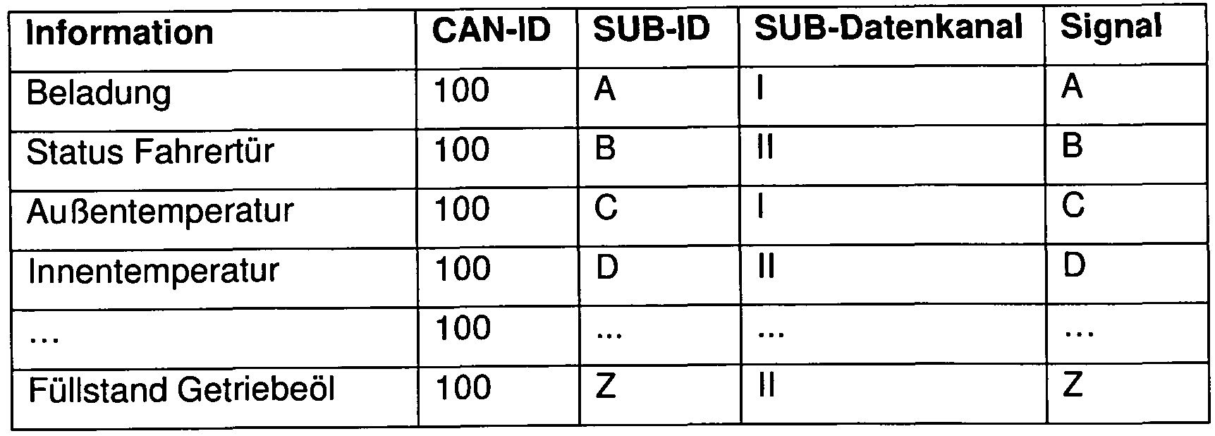
- a CAN message block with the exemplarily selected or newly defined CAN-ID 100 contains, as usual, 8 bytes of information.
- the first 2 bytes here denote a SUB identifier, namely a SUB-ID A. This is followed by 2 bytes to represent a signal A and subsequently a SUB-ID B and a signal B.
- the signals A and B are contents of SUB data channels I, II within the CAN message with the CAN-ID 100.
- the existing in the commercial vehicle EBS-ECU knows the described data structure and interprets a message with the CAN-ID 100 accordingly. The same applies to recipients who should interpret the message. In the present case, two SUB-IDs and the associated signals are provided for each CAN message.
- the SUB data channels I, II can be used individually and can transmit almost any desired signals, for example according to the following table (for the signals A-Z):
- the signal sensor A supplies a signal A to the EBS-ECU, the signal sensor B provides a signal B, etc.
- the signals are provided with their own identifier in the EBS-ECU.
- the signal A receives the SUB-ID A, etc. Subsequently, SUB-ID A, signal A, SUB-ID B and signal B of the CAN message associated with the CAN-ID 100 and transmitted as a CAN message to the telematics ECU.
- the resulting CAN messages are sent via a cellular connection (UMTS) to a receiver, such as a web server of a telematics portal for visualization of telematics data, and can be queried or viewed by the user via the Internet, eg. B. via a browser software on the user's computer.
- UMTS cellular connection
- the user can distinguish the signals C and D from the signals A and B on the basis of the SUB-IDs, despite identical CAN-ID 100. Only the software on the user client on the one hand and the software on the EBS-ECU on the other hand, the importance of Know sub-IDs to understand the underlying information.
- the telematics ECU and web server merely relay the CAN message with the CAN-ID 100.
- Fig. 1 the arrows of the information channels CAN bus, UMTS and Internet are drawn as double arrows. Associated with this is the function of polling a particular signal. Thus, the user can selectively query the signal of the sensor A. The EBS-ECU then creates and sends a CAN message with the SUB-ID A and the current signal A.
- signals from sensors can also be linked with each other based on stored functions.
- the result of the link receives a SUB-ID and is transmitted as part of the CAN message with the CAN-ID 100.
- the functions stored in the EBS-ECU can be changed by parameters transmitted by the user, with the result that new, modified functions result with correspondingly new signals, which in turn can be sent with their own SUB-ID as part of a CAN message.
- the invention is explained exclusively in connection with CAN messages. However, the invention can also be used in conjunction with other message formats, in particular with bus systems and predefined data packets. It is important to create and use SUB channels within existing data structures.
- Main field of application of the invention is the communication via a CAN bus system in a vehicle, in particular in conjunction with a telematics function. With the aid of the invention, a large number of different signals obtained in the vehicle can be transmitted via the CAN bus to a receiver with high flexibility.
Abstract
Description
Claims
Priority Applications (2)
| Application Number | Priority Date | Filing Date | Title |
|---|---|---|---|
| US14/916,896 US20160197740A1 (en) | 2013-09-13 | 2014-07-10 | Method for the provision and transmission of data, in particular with a link to a vehicle |
| EP14738392.1A EP3044912A1 (en) | 2013-09-13 | 2014-07-10 | Method for the provision and transmission of data, in particular with a link to a vehicle |
Applications Claiming Priority (2)
| Application Number | Priority Date | Filing Date | Title |
|---|---|---|---|
| DE102013015370.0A DE102013015370A1 (en) | 2013-09-13 | 2013-09-13 | Method for providing and transmitting data, in particular in connection with a vehicle |
| DE102013015370.0 | 2013-09-13 |
Publications (1)
| Publication Number | Publication Date |
|---|---|
| WO2015036068A1 true WO2015036068A1 (en) | 2015-03-19 |
Family
ID=51176329
Family Applications (1)
| Application Number | Title | Priority Date | Filing Date |
|---|---|---|---|
| PCT/EP2014/001889 WO2015036068A1 (en) | 2013-09-13 | 2014-07-10 | Method for the provision and transmission of data, in particular with a link to a vehicle |
Country Status (4)
| Country | Link |
|---|---|
| US (1) | US20160197740A1 (en) |
| EP (1) | EP3044912A1 (en) |
| DE (1) | DE102013015370A1 (en) |
| WO (1) | WO2015036068A1 (en) |
Families Citing this family (4)
| Publication number | Priority date | Publication date | Assignee | Title |
|---|---|---|---|---|
| US10388161B2 (en) | 2015-09-16 | 2019-08-20 | Truck-Lite Co., Llc | Telematics road ready system with user interface |
| US10093232B2 (en) | 2015-09-16 | 2018-10-09 | Truck-Lite Co., Llc | Telematics road ready system |
| US20190268675A1 (en) | 2017-03-15 | 2019-08-29 | Scott Troutman | Telematics Road Ready System including a Bridge Integrator Unit |
| SE545249C2 (en) | 2017-12-27 | 2023-06-07 | Scania Cv Ab | Method and control unit for configuring an add-on interface of a vehicle |
Citations (2)
| Publication number | Priority date | Publication date | Assignee | Title |
|---|---|---|---|---|
| EP1158718A2 (en) * | 2000-05-24 | 2001-11-28 | General Motors Corporation | In-vehicle network management using virtual networks |
| US20070038782A1 (en) * | 2005-07-26 | 2007-02-15 | Ambric, Inc. | System of virtual data channels across clock boundaries in an integrated circuit |
Family Cites Families (25)
| Publication number | Priority date | Publication date | Assignee | Title |
|---|---|---|---|---|
| US20040205111A1 (en) * | 2002-11-15 | 2004-10-14 | Zaki Chasmawala | User configurable data messages in industrial networks |
| DE10360125A1 (en) * | 2003-12-20 | 2005-07-21 | Daimlerchrysler Ag | Data loggin in a motor vehicle |
| US7630807B2 (en) * | 2004-07-15 | 2009-12-08 | Hitachi, Ltd. | Vehicle control system |
| JP4259456B2 (en) * | 2004-11-11 | 2009-04-30 | トヨタ自動車株式会社 | Data recording apparatus and data recording method |
| JP2006333438A (en) * | 2005-04-28 | 2006-12-07 | Fujitsu Ten Ltd | Gateway apparatus and routing method |
| US20060276184A1 (en) * | 2005-06-01 | 2006-12-07 | General Motors Corporation | Method and system for in-vehicle messaging management |
| JP4376862B2 (en) * | 2005-12-20 | 2009-12-02 | 富士通テン株式会社 | Communication message conversion apparatus and communication message conversion method |
| JP4804307B2 (en) * | 2006-10-27 | 2011-11-02 | 富士通テン株式会社 | Gateway apparatus and transfer control method |
| US7826944B2 (en) * | 2006-12-14 | 2010-11-02 | General Motors Llc | Configurable vehicle bus storage cache mechanism |
| US7975120B2 (en) * | 2006-12-27 | 2011-07-05 | Freescale Semiconductor, Inc. | Dynamic allocation of message buffers |
| JP4987760B2 (en) * | 2008-03-05 | 2012-07-25 | 株式会社オートネットワーク技術研究所 | Relay device, communication system, and communication method |
| JP4581037B2 (en) * | 2008-07-10 | 2010-11-17 | 国立大学法人名古屋大学 | Relay device, communication system, and communication method |
| JP4621837B2 (en) * | 2008-07-10 | 2011-01-26 | 国立大学法人名古屋大学 | Relay device, communication system, and communication method |
| US9998697B2 (en) * | 2009-03-02 | 2018-06-12 | Flir Systems, Inc. | Systems and methods for monitoring vehicle occupants |
| JP4803278B2 (en) * | 2009-04-07 | 2011-10-26 | 株式会社デンソー | Inspection system and in-vehicle device |
| JP5363379B2 (en) * | 2009-05-20 | 2013-12-11 | ルネサスエレクトロニクス株式会社 | Communications system |
| CN102666207A (en) * | 2009-09-29 | 2012-09-12 | 沃尔沃技术公司 | Method and system for preparing sensor output data of a sensor assembly for further processing in at least one application and/or by at least one algorithm |
| JP5717240B2 (en) * | 2010-08-09 | 2015-05-13 | 国立大学法人名古屋大学 | Communication system and communication apparatus |
| US8863256B1 (en) * | 2011-01-14 | 2014-10-14 | Cisco Technology, Inc. | System and method for enabling secure transactions using flexible identity management in a vehicular environment |
| US8930036B2 (en) * | 2011-04-13 | 2015-01-06 | GM Global Technology Operations LLC | Reconfigurable interface-based electrical architecture |
| US9061592B2 (en) * | 2012-01-24 | 2015-06-23 | Toyota Motor Engineering & Manufacturing North America, Inc. | System and method for detecting power integrator malfunction |
| DE102012204586A1 (en) * | 2012-03-22 | 2013-10-17 | Bayerische Motoren Werke Aktiengesellschaft | Gateway, node and method for a vehicle |
| EP2832070B1 (en) * | 2012-03-29 | 2020-05-20 | Arilou Information Security Technologies Ltd. | Device for protecting a vehicle electronic system |
| JP5637190B2 (en) * | 2012-07-27 | 2014-12-10 | トヨタ自動車株式会社 | Communication system and communication method |
| US9471528B2 (en) * | 2012-11-02 | 2016-10-18 | Nxp B.V. | Controller area network (CAN) transceiver and method for operating a CAN transceiver |
-
2013
- 2013-09-13 DE DE102013015370.0A patent/DE102013015370A1/en not_active Withdrawn
-
2014
- 2014-07-10 US US14/916,896 patent/US20160197740A1/en not_active Abandoned
- 2014-07-10 EP EP14738392.1A patent/EP3044912A1/en not_active Withdrawn
- 2014-07-10 WO PCT/EP2014/001889 patent/WO2015036068A1/en active Application Filing
Patent Citations (2)
| Publication number | Priority date | Publication date | Assignee | Title |
|---|---|---|---|---|
| EP1158718A2 (en) * | 2000-05-24 | 2001-11-28 | General Motors Corporation | In-vehicle network management using virtual networks |
| US20070038782A1 (en) * | 2005-07-26 | 2007-02-15 | Ambric, Inc. | System of virtual data channels across clock boundaries in an integrated circuit |
Non-Patent Citations (2)
| Title |
|---|
| "IEEE P1823(TM)/D201207171200 Draft Standard for Universal Power Adapter for Mobile Devices ; UPAMD_P1823Draft_20120717", IEEE DRAFT; UPAMD_P1823DRAFT_201207171200, IEEE-SA, PISCATAWAY, NJ USA, vol. msc.upamd, 18 July 2012 (2012-07-18), pages 1 - 118, XP068029380 * |
| See also references of EP3044912A1 * |
Also Published As
| Publication number | Publication date |
|---|---|
| EP3044912A1 (en) | 2016-07-20 |
| DE102013015370A1 (en) | 2015-03-19 |
| US20160197740A1 (en) | 2016-07-07 |
Similar Documents
| Publication | Publication Date | Title |
|---|---|---|
| EP3661131B1 (en) | Method for transmitting data via a serial communication bus, bus interface designed for this purpose, and correspondingly designed computer program | |
| DE102018103187A1 (en) | Extended central gateway for vehicle networking | |
| DE102016218982B3 (en) | Method for communicating vehicles | |
| DE10225786A1 (en) | Method and device for transmitting, transmitting and / or receiving information in connection with a vehicle | |
| EP2795848B1 (en) | Subscriber station of a bus system and method for transferring messages between subscriber stations of a bus system | |
| EP3788756B1 (en) | Gateway for data communication in a vehicle | |
| WO2015036068A1 (en) | Method for the provision and transmission of data, in particular with a link to a vehicle | |
| EP3596889A1 (en) | Method for establishing a wireless data link | |
| EP3326333B1 (en) | Bus system, subscriber station therefor and method for configuring a static bus system for a dynamic communication | |
| DE102017012214B4 (en) | Method for transmitting data via a serial communication bus, appropriately designed bus interface and computer program designed accordingly | |
| DE102013012368A1 (en) | Motor vehicle electrical system and method for transmitting data signals in a motor vehicle electrical system | |
| WO2021122362A1 (en) | Communication between networks of a motor vehicle | |
| DE102014208084A1 (en) | Estimate a reception probability of a data packet and a transmission rate for data packets | |
| EP3345351B1 (en) | Method, device, and computer program for operating a data processing system | |
| DE102008039170B4 (en) | Automatic configuration of subsystems and communication between systems in vehicles | |
| EP1644231A1 (en) | Device for communicating with control devices in a vehicle | |
| DE102018220324A1 (en) | Method for monitoring a data transmission system, data transmission system and motor vehicle | |
| DE102004020880B4 (en) | Interface for communication between vehicle applications and vehicle bus systems | |
| WO2012052270A2 (en) | Network | |
| EP2651079A1 (en) | Electrical installation arrangement | |
| DE102017211153A1 (en) | Method and device for transmitting data between a first communication network of a first tracked vehicle unit and a second communication network of a second tracked vehicle unit | |
| DE102019109597B4 (en) | Method, bus system and means of transportation for controlling utilization of the bus system of the means of transportation | |
| EP1642422B1 (en) | Adaptation of a vehicle network to modified requirements | |
| DE102020213522A1 (en) | Method of operating a security system | |
| DE10144316A1 (en) | Bus system following master-slave principle uses echo message with reaction time information with respect to time interval in which response message from slave can be anticipated |
Legal Events
| Date | Code | Title | Description |
|---|---|---|---|
| 121 | Ep: the epo has been informed by wipo that ep was designated in this application |
Ref document number: 14738392 Country of ref document: EP Kind code of ref document: A1 |
|
| REEP | Request for entry into the european phase |
Ref document number: 2014738392 Country of ref document: EP |
|
| WWE | Wipo information: entry into national phase |
Ref document number: 2014738392 Country of ref document: EP |
|
| WWE | Wipo information: entry into national phase |
Ref document number: 14916896 Country of ref document: US |
|
| NENP | Non-entry into the national phase |
Ref country code: DE |
|
| REG | Reference to national code |
Ref country code: BR Ref legal event code: B01A Ref document number: 112016005525 Country of ref document: BR |
|
| ENP | Entry into the national phase |
Ref document number: 112016005525 Country of ref document: BR Kind code of ref document: A2 Effective date: 20160311 |