WO2015008531A1 - Display device - Google Patents
Display device Download PDFInfo
- Publication number
- WO2015008531A1 WO2015008531A1 PCT/JP2014/063034 JP2014063034W WO2015008531A1 WO 2015008531 A1 WO2015008531 A1 WO 2015008531A1 JP 2014063034 W JP2014063034 W JP 2014063034W WO 2015008531 A1 WO2015008531 A1 WO 2015008531A1
- Authority
- WO
- WIPO (PCT)
- Prior art keywords
- image
- display device
- image forming
- forming apparatus
- optical system
- Prior art date
Links
- 230000003287 optical effect Effects 0.000 claims abstract description 192
- 210000001747 pupil Anatomy 0.000 claims abstract description 86
- 238000012937 correction Methods 0.000 claims abstract description 34
- 230000015572 biosynthetic process Effects 0.000 claims abstract description 6
- 230000002093 peripheral effect Effects 0.000 claims description 27
- 241000226585 Antennaria plantaginifolia Species 0.000 claims description 9
- 238000005401 electroluminescence Methods 0.000 claims description 3
- NJPPVKZQTLUDBO-UHFFFAOYSA-N novaluron Chemical compound C1=C(Cl)C(OC(F)(F)C(OC(F)(F)F)F)=CC=C1NC(=O)NC(=O)C1=C(F)C=CC=C1F NJPPVKZQTLUDBO-UHFFFAOYSA-N 0.000 description 11
- 210000003128 head Anatomy 0.000 description 10
- 239000000463 material Substances 0.000 description 9
- 238000010586 diagram Methods 0.000 description 8
- 238000012986 modification Methods 0.000 description 8
- 230000004048 modification Effects 0.000 description 8
- 239000000853 adhesive Substances 0.000 description 5
- 230000001070 adhesive effect Effects 0.000 description 5
- 210000001061 forehead Anatomy 0.000 description 5
- 238000000034 method Methods 0.000 description 5
- 230000004304 visual acuity Effects 0.000 description 5
- 238000012545 processing Methods 0.000 description 4
- 239000000758 substrate Substances 0.000 description 4
- 229910052782 aluminium Inorganic materials 0.000 description 3
- XAGFODPZIPBFFR-UHFFFAOYSA-N aluminium Chemical compound [Al] XAGFODPZIPBFFR-UHFFFAOYSA-N 0.000 description 3
- 238000013459 approach Methods 0.000 description 2
- 238000001514 detection method Methods 0.000 description 2
- 239000004973 liquid crystal related substance Substances 0.000 description 2
- 230000005499 meniscus Effects 0.000 description 2
- 229920003023 plastic Polymers 0.000 description 2
- 238000004088 simulation Methods 0.000 description 2
- 230000000007 visual effect Effects 0.000 description 2
- 229920000049 Carbon (fiber) Polymers 0.000 description 1
- 235000004035 Cryptotaenia japonica Nutrition 0.000 description 1
- 102000007641 Trefoil Factors Human genes 0.000 description 1
- 235000015724 Trifolium pratense Nutrition 0.000 description 1
- 229920000122 acrylonitrile butadiene styrene Polymers 0.000 description 1
- 230000002730 additional effect Effects 0.000 description 1
- 239000000956 alloy Substances 0.000 description 1
- 238000005452 bending Methods 0.000 description 1
- 239000004917 carbon fiber Substances 0.000 description 1
- 239000002131 composite material Substances 0.000 description 1
- 238000013461 design Methods 0.000 description 1
- 230000000694 effects Effects 0.000 description 1
- 239000013013 elastic material Substances 0.000 description 1
- 238000002474 experimental method Methods 0.000 description 1
- 238000000605 extraction Methods 0.000 description 1
- 239000007769 metal material Substances 0.000 description 1
- VNWKTOKETHGBQD-UHFFFAOYSA-N methane Chemical compound C VNWKTOKETHGBQD-UHFFFAOYSA-N 0.000 description 1
- 208000001491 myopia Diseases 0.000 description 1
- 238000005457 optimization Methods 0.000 description 1
- 230000001105 regulatory effect Effects 0.000 description 1
- 230000000452 restraining effect Effects 0.000 description 1
- 210000001525 retina Anatomy 0.000 description 1
- 239000007787 solid Substances 0.000 description 1
Images


Classifications
-
- G—PHYSICS
- G02—OPTICS
- G02B—OPTICAL ELEMENTS, SYSTEMS OR APPARATUS
- G02B27/00—Optical systems or apparatus not provided for by any of the groups G02B1/00 - G02B26/00, G02B30/00
- G02B27/01—Head-up displays
- G02B27/017—Head mounted
- G02B27/0172—Head mounted characterised by optical features
-
- G—PHYSICS
- G02—OPTICS
- G02B—OPTICAL ELEMENTS, SYSTEMS OR APPARATUS
- G02B27/00—Optical systems or apparatus not provided for by any of the groups G02B1/00 - G02B26/00, G02B30/00
- G02B27/01—Head-up displays
- G02B27/017—Head mounted
-
- G—PHYSICS
- G02—OPTICS
- G02B—OPTICAL ELEMENTS, SYSTEMS OR APPARATUS
- G02B27/00—Optical systems or apparatus not provided for by any of the groups G02B1/00 - G02B26/00, G02B30/00
- G02B27/01—Head-up displays
- G02B27/017—Head mounted
- G02B27/0176—Head mounted characterised by mechanical features
-
- G—PHYSICS
- G02—OPTICS
- G02B—OPTICAL ELEMENTS, SYSTEMS OR APPARATUS
- G02B27/00—Optical systems or apparatus not provided for by any of the groups G02B1/00 - G02B26/00, G02B30/00
- G02B27/02—Viewing or reading apparatus
-
- G—PHYSICS
- G06—COMPUTING; CALCULATING OR COUNTING
- G06T—IMAGE DATA PROCESSING OR GENERATION, IN GENERAL
- G06T5/00—Image enhancement or restoration
-
- G—PHYSICS
- G06—COMPUTING; CALCULATING OR COUNTING
- G06T—IMAGE DATA PROCESSING OR GENERATION, IN GENERAL
- G06T5/00—Image enhancement or restoration
- G06T5/80—Geometric correction
-
- H—ELECTRICITY
- H04—ELECTRIC COMMUNICATION TECHNIQUE
- H04N—PICTORIAL COMMUNICATION, e.g. TELEVISION
- H04N5/00—Details of television systems
- H04N5/64—Constructional details of receivers, e.g. cabinets or dust covers
-
- H—ELECTRICITY
- H04—ELECTRIC COMMUNICATION TECHNIQUE
- H04N—PICTORIAL COMMUNICATION, e.g. TELEVISION
- H04N5/00—Details of television systems
- H04N5/74—Projection arrangements for image reproduction, e.g. using eidophor
- H04N5/7475—Constructional details of television projection apparatus
- H04N5/7491—Constructional details of television projection apparatus of head mounted projectors
-
- G—PHYSICS
- G02—OPTICS
- G02B—OPTICAL ELEMENTS, SYSTEMS OR APPARATUS
- G02B27/00—Optical systems or apparatus not provided for by any of the groups G02B1/00 - G02B26/00, G02B30/00
- G02B27/01—Head-up displays
- G02B27/0101—Head-up displays characterised by optical features
- G02B2027/011—Head-up displays characterised by optical features comprising device for correcting geometrical aberrations, distortion
-
- G—PHYSICS
- G02—OPTICS
- G02B—OPTICAL ELEMENTS, SYSTEMS OR APPARATUS
- G02B27/00—Optical systems or apparatus not provided for by any of the groups G02B1/00 - G02B26/00, G02B30/00
- G02B27/01—Head-up displays
- G02B27/0101—Head-up displays characterised by optical features
- G02B2027/0132—Head-up displays characterised by optical features comprising binocular systems
-
- G—PHYSICS
- G02—OPTICS
- G02B—OPTICAL ELEMENTS, SYSTEMS OR APPARATUS
- G02B27/00—Optical systems or apparatus not provided for by any of the groups G02B1/00 - G02B26/00, G02B30/00
- G02B27/01—Head-up displays
- G02B27/0101—Head-up displays characterised by optical features
- G02B2027/014—Head-up displays characterised by optical features comprising information/image processing systems
-
- G—PHYSICS
- G02—OPTICS
- G02B—OPTICAL ELEMENTS, SYSTEMS OR APPARATUS
- G02B27/00—Optical systems or apparatus not provided for by any of the groups G02B1/00 - G02B26/00, G02B30/00
- G02B27/01—Head-up displays
- G02B27/0101—Head-up displays characterised by optical features
- G02B2027/0147—Head-up displays characterised by optical features comprising a device modifying the resolution of the displayed image
-
- G—PHYSICS
- G02—OPTICS
- G02B—OPTICAL ELEMENTS, SYSTEMS OR APPARATUS
- G02B27/00—Optical systems or apparatus not provided for by any of the groups G02B1/00 - G02B26/00, G02B30/00
- G02B27/01—Head-up displays
- G02B27/0149—Head-up displays characterised by mechanical features
- G02B2027/015—Head-up displays characterised by mechanical features involving arrangement aiming to get less bulky devices
-
- G—PHYSICS
- G02—OPTICS
- G02B—OPTICAL ELEMENTS, SYSTEMS OR APPARATUS
- G02B27/00—Optical systems or apparatus not provided for by any of the groups G02B1/00 - G02B26/00, G02B30/00
- G02B27/01—Head-up displays
- G02B27/0149—Head-up displays characterised by mechanical features
- G02B2027/0154—Head-up displays characterised by mechanical features with movable elements
- G02B2027/0159—Head-up displays characterised by mechanical features with movable elements with mechanical means other than scaning means for positioning the whole image
Definitions
- the present disclosure relates to a display device, and more specifically to a display device that can be used as, for example, a head-mounted display (HMD).
- HMD head-mounted display
- a virtual image display device for allowing an observer to observe a two-dimensional image formed by an image forming device as an enlarged virtual image by a virtual image optical system is known from, for example, Japanese Patent Laid-Open No. 5-134208.
- the liquid crystal display unit is illuminated with light from a light source collimated by a lens through a polarizing plate, and the image light of the illuminated liquid crystal display unit is emitted.
- the collected light is focused on the first focal point by the lens group, and the condensed light is reflected by the concave mirror, is condensed on the second focal point by the front lens of the pupil via the polarizing plate, and reaches the retina. .
- the user can observe the image.
- the virtual image display device is composed of a plurality of optical systems (lens, lens group, and concave mirror), so that the virtual image display device is still large, small, and lightweight. This is insufficient.
- the image reaching the observer is distorted or the resolution of the image is not uniform.
- a first object of the present disclosure is to provide an image forming apparatus having a simple configuration and structure for achieving a large viewing angle while being small and light, and further, an image observed by an observer is distorted.
- the object is to provide a display device that is unlikely to occur.
- a second object of the present disclosure is to provide an image forming apparatus having a simple configuration and structure for achieving a large viewing angle while being small and light, and in addition to the resolution of an image observed by an observer.
- An object of the present invention is to provide a display device capable of suppressing a large difference / change depending on the angle of view.
- the display device for achieving the first object is as follows.
- a display device comprising: The image display device (A) an image forming apparatus, and (B) an optical system for guiding an image from the image forming apparatus to the pupil of the observer;
- the direction of the image forming apparatus corresponding to the first direction of the image is the X direction
- the direction of the image forming apparatus corresponding to the second direction of the image different from the first direction is the Y direction
- the distortion correction device corrects an input image signal, thereby correcting distortion of an observed image.
- the first direction or the X direction corresponds to the horizontal direction of the image finally reaching the observer's pupil
- the second direction or the Y direction is the image finally reaching the observer's pupil.
- a form corresponding to the vertical direction can be adopted.
- the X direction and the Y direction may be orthogonal or may not be orthogonal. The same applies to the following description.
- the display device for achieving the second object described above, (B) Frame and (B) an image display device attached to the frame;
- a display device comprising: The image display device (A) an image forming apparatus, and (B) an optical system for guiding an image from the image forming apparatus to the pupil of the observer; With When the direction of the image forming apparatus corresponding to the first direction of the image is the X direction and the direction of the image forming apparatus corresponding to the second direction of the image different from the first direction is the Y direction, the image forming apparatus Curved along the X direction, the Y direction, or the X direction and the Y direction, An optical system is arranged so that an image displayed on the image forming apparatus reaches the observer's pupil in a defocused state.
- the image forming apparatus is curved, for example, the optical path length of light emitted from the central portion of the image forming apparatus, and the image
- a large viewing angle can be achieved while being small and lightweight.
- the display device according to the first aspect of the present disclosure includes the distortion correction device, it is difficult for the image observed by the observer to be distorted.
- the optical system is arranged so that the image displayed on the image forming apparatus reaches the observer's pupil in the defocused state. It is difficult for differences and changes depending on the angle of view to occur in the resolution of the image observed by the person. Note that the effects described in the present specification are merely examples and are not limited, and may have additional effects.
- FIGS. 1A, 1B, 1C, and 1D are conceptual diagrams for explaining what an observed image looks like in the display device according to the first embodiment depending on the presence or absence of distortion correction for an image signal.
- the optical system is arranged so that the image displayed on the image forming apparatus of the display apparatus according to the fifth embodiment reaches the observer's pupil in the defocused state and the just-focused state. It is a figure which shows the result of having simulated the horizontal direction resolution of the image which an observer observes.
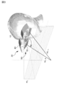
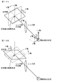
- FIG. 3 is a perspective view of the main part of the display device when the observer wears the display device.
- FIG. 4 is a view of a plane mirror and the like constituting the optical system of the right-eye image display device as viewed from the x-axis direction.
- FIG. 5 is a conceptual diagram (perspective view) of the image forming apparatus and the optical system as viewed from the observer side.
- FIG. 6 is a conceptual diagram (perspective view) of the image forming apparatus and the optical system as viewed from above.
- 7A and 7B are a perspective view of a main part of the display device when the observer wearing the display device of Example 1 is viewed from the front, and a display device when the observer wearing the display device is viewed from the side. It is a perspective view of the principal part.
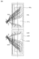
- FIG. 8A and 8B are perspective views of the image forming apparatus and the optical system when the image forming apparatus and the optical system are viewed from the observer in the display apparatus according to the first embodiment, respectively, and the image forming apparatus and the optical system from the observer. It is these perspective views when it looks.
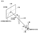
- FIG. 9 is a conceptual diagram of a reflecting mirror and the like for explaining an arrangement state of the reflecting mirrors constituting the optical system.
- FIG. 10A and FIG. 10B are conceptual diagrams of reflectors and the like for explaining the arrangement state of the reflectors constituting the optical system, following FIG.
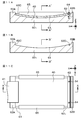
- FIG. 11A is a schematic cross-sectional view of a support member and an image forming apparatus that constitute the display device of Example 1, FIG.
- FIG. 11B is a schematic cross-sectional view of the support member
- FIG. 1 is a schematic plan view of an image forming apparatus
- 12A and 12B are a schematic cross-sectional view of the support member and the image forming apparatus constituting the display device of Example 1 taken along the arrow A′-A ′ in FIG. 11A, and the arrow in FIG. 11B of the support member.
- FIG. 6 is a schematic cross-sectional view along B′-B ′.
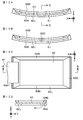
- FIG. 13A is a schematic cross-sectional view of a support member and an image forming apparatus that constitute the display device of Example 2
- FIG. 13B is a schematic cross-sectional view of the support member
- FIG. 13D is a schematic plan view of the image forming apparatus
- FIG. 13D is a schematic cross-sectional view of the support member and the image forming apparatus along the arrow DD in FIG. 13A.
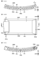
- FIG. 14A is a schematic cross-sectional view of a support member and an image forming apparatus that constitute the display device of Example 3
- FIG. 14B is a schematic plan view of the support member and the image forming apparatus
- FIG. 10 is a schematic cross-sectional view of a support member and an image forming apparatus that constitute a modification of the display device of Example 3.
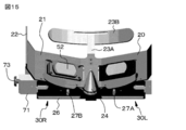
- FIG. 15 is a perspective view of a part of the display device according to the first embodiment. 16A, FIG. 16B, FIG. 16C, and FIG.
- 16D are a bottom view, a top view, a right side view, and a rear view, respectively, of the display device of Example 1.
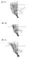
- 17A, 17B, and 17C are diagrams illustrating how images from the image forming apparatus are formed by various lens groups.
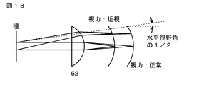
- FIG. 18 is a diagram conceptually illustrating a state in which the distance between the image forming apparatus and the optical system is adjusted by the image forming apparatus / optical system distance / adjustment apparatus.
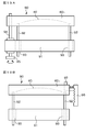
- 19A and 19B are schematic views of the image forming apparatus / optical system distance / adjustment apparatus.
- Example 1 Display device according to first and second aspects of the present disclosure
- Example 2 Modification of Example 1 4
- Example 3 Modification of Example 2
- Example 4 Modification of Examples 1 to 3) 6
- Example 5 display device according to the second aspect of the present disclosure
- the display device according to the first aspect of the present disclosure and the display device according to the second aspect of the present disclosure may be collectively referred to as “a display device of the present disclosure”.
- the distortion correction device corrects the input image signal so as to give barrel distortion or pincushion distortion to the input image signal to be corrected. It can be. That is, in the image forming apparatus, an image is displayed in a state where barrel distortion or pincushion distortion occurs.
- the distortion as a characteristic of the lens group is often pincushioned, and it is desirable to give barrel distortion to the image signal.
- the distortion as a characteristic of the lens group is often barrel-shaped, and it is desirable to give a pincushion distortion to the image signal.
- the distortion correction device itself can have a known circuit configuration.
- the distortion correction device includes an image signal corresponding to at least portions of the input image signal located at both ends and in the vicinity thereof.
- the image distortion can be corrected at least at both ends of the image forming apparatus and in the vicinity thereof.
- the image forming apparatus When the image forming apparatus is curved along the X direction, it is preferable to correct image signals corresponding to at least both ends along the Y direction of the image forming apparatus and the vicinity thereof. In addition, when the image forming apparatus is curved along the Y direction, it is preferable to correct image signals corresponding to at least both ends of the image forming apparatus along the X direction and the vicinity thereof. Further, when the image forming apparatus is curved along the X direction and the Y direction, the image signals corresponding to at least both ends of the image forming apparatus along the X direction and the Y direction and the vicinity thereof are corrected. It is preferable to do.
- the optical system is arranged so that the image displayed on the image forming apparatus reaches the observer's pupil in a defocused state (out-of-focus state).
- the horizontal resolution of the image can be made uniform.
- the distance between the image forming apparatus and the optical system are configured. Control and optimization of the distance between the lens group (to be described later) may be achieved.
- the optical system is disposed between the reflecting mirror that reflects the image from the image forming apparatus, and the observer's pupil and the reflecting mirror. It can be made into the form which consists of a lens group into which the image reflected by the reflecting mirror injects. In this case, the image forming apparatus can be arranged above the reflecting mirror.
- the image display apparatus further includes a support member that supports the image forming apparatus,
- the support surface of the support member that supports the image forming apparatus is curved along the X direction, the Y direction, or the X direction and the Y direction, so that the image forming apparatus is curved. be able to.
- the image forming apparatus can be curved based on a simple configuration and structure. Note that the display device having such a configuration is referred to as a “display device having the first configuration of the present disclosure” for convenience.
- the degree of curvature along the X direction of the support surface of the support member may be larger than the degree of curvature along the Y direction. That is, when the degree of curvature is represented by an average radius of curvature, the average radius of curvature along the X direction of the support surface of the support member can be smaller than the average radius of curvature along the Y direction.
- the support member includes a pressing member
- the outer shape of the image forming apparatus is a rectangular shape
- the outer peripheral portion of the image forming apparatus extending along the X direction can be configured to be fixed to the support member by a pressing member.
- the outer peripheral portion of the image forming apparatus refers to an area (so-called frame area) between the end of the image forming apparatus and the end of the display area of the image forming apparatus.
- the outer shape of the image forming apparatus is a rectangular shape
- the outer peripheral portion of the image forming apparatus extending along the X direction can be sandwiched between support members.
- the image forming apparatus may be fixed to the support member using an adhesive.
- the support member may be made of, for example, various plastic materials including ABS resin, a composite material such as Unitate (registered trademark, manufactured by Unitika Ltd.) and FRP, a metal material such as carbon fiber and aluminum, and an alloy material.
- the image display device includes an image forming apparatus and an optical system (specifically, Can be configured to include an image forming apparatus / optical system distance / adjusting device for adjusting the distance to the reflecting mirror.
- the display device having such a configuration is referred to as a “display device having the second configuration of the present disclosure” for convenience.
- the image forming device / optical system distance / adjustment device it is possible to appropriately and easily cope with the difference in the visual acuity of the observer depending on the observer, despite the simple configuration and structure. Is possible.
- a display control device that controls the size of the entire image from the image forming device according to the distance between the image forming device and the optical system is provided. Furthermore, it can be set as the structure provided.
- the distance between the image forming apparatus and the optical system is the distance at which the distance between the image forming apparatus and the optical system (specifically, the reflecting mirror) is detected by the distance / adjustment apparatus between the image forming apparatus and the optical system.
- a detection device may be arranged.
- the distance detection device may be an appropriate device depending on the configuration and structure of the image forming device / optical system distance / adjustment device.
- the overall image size is controlled by performing various signal processing (for example, thinning processing and interpolation processing) on the image signal used to form the image in the image forming apparatus, thereby enlarging / reducing the overall image size. It is possible to use a well-known control method such as
- an image display device can be configured to include a pupil / optical system distance / adjustment device that adjusts the distance between the optical system (specifically, the reflecting mirror) and the pupil of the observer.
- the display device having such a configuration is referred to as a “display device having the third configuration of the present disclosure” for convenience.
- the pupil / optical system distance / adjustment device the distance between the observer's pupil and the lens group can be adjusted appropriately and easily despite the simple configuration and structure. Adjustable.
- the display device of the present disclosure including the various preferable modes and configurations described above (the display device of the first configuration of the present disclosure, the display device of the second configuration of the present disclosure, the third configuration of the present disclosure)
- the image forming apparatus passes through a predetermined point (for example, an image forming apparatus optical axis collision point described later), the axis parallel to the X direction is the X axis, and the predetermined point (for example, the image forming apparatus is included).
- the image display device forms an image with at least one of the X, Y, and Z axes as the center when the axis parallel to the Y direction is defined as the Y axis. It can be set as the structure further provided with the rotation apparatus which rotates an apparatus.
- a rotating device that rotates the image forming apparatus around the X axis a rotating device that rotates the image forming apparatus around the Y axis, and a rotation that rotates the image forming apparatus around the Z axis.
- Moving device, rotating device for rotating the image forming apparatus about the X axis and Y axis, rotating device for rotating the image forming apparatus about the X axis and Z axis, and image about the Y axis and Z axis Examples thereof include a rotation device that rotates the forming device, and a rotation device that rotates the image forming device around the X, Y, and Z axes.
- the display device of the present disclosure including the above-described various preferable forms and configurations including the configuration described above (the display device of the first configuration of the present disclosure, the display device of the second configuration of the present disclosure)
- the display device of the third configuration of the present disclosure includes a moving device that moves the image forming device along the X direction with respect to the optical system (specifically, the reflecting mirror). can do.
- the display device of the present disclosure including the above-described preferred embodiments and configurations (the display device of the first configuration of the present disclosure, the display device of the second configuration of the present disclosure, the display device of the third configuration of the present disclosure) Including)
- the image display device for the left eye and the image display device for the right eye are attached to the frame,
- Each image display device (A) an image forming apparatus, and (B) an optical system for guiding an image from the image forming apparatus to the pupil of the observer; It can be set as the form provided with.
- a display device is referred to as a “binocular display device of the present disclosure” for convenience.
- the optical system includes a reflecting mirror that reflects an image from the image forming apparatus, and a lens group that is disposed between the observer's pupil and the reflecting mirror and into which the image reflected by the reflecting mirror is incident.
- the normal of the reflecting mirror that constitutes the optical system of the left-eye image display device and the normal of the reflecting mirror that constitutes the optical system of the right-eye image display device are opposite to the observer with respect to the reflecting mirror. It can be a form that intersects in space. By adopting such a form, two image forming apparatuses can be easily juxtaposed with a high degree of design freedom.
- the normal of the reflecting mirror that constitutes the optical system of the image display apparatus for the left eye and the normal of the reflecting mirror that constitutes the optical system of the image display apparatus for the right eye It is possible to adopt a configuration in which they intersect below a virtual plane (the xy plane described below) including both the pupils of the person and infinity.
- the arrangement state of the reflecting mirrors is A virtual plane including both the pupils of the observer and infinity is the xy plane, and a straight line connecting both the pupils of the observer is an x axis (specifically, a straight line connecting both the pupils of the observer,
- the axis line from the observer's right eye pupil to the left eye pupil is the x axis, and the optical axis of the observer right eye is the y axis (specifically, the axis line orthogonal to the x axis and toward the lens group side is y-axis)
- the point of the reflecting mirror where the optical axis (optical principal axis) of the lens group constituting the optical system of the right-eye image display device collides with the reflecting mirror is defined as the “right-eye reflecting mirror optical axis collision point”.
- the reflecting mirrors constituting the optical system of the ophthalmic image display device are arranged in parallel (perpendicularly) to the xz plane (see FIG. 9), and further pass through the optical axis collision point of the right-eye reflector.
- the axis on the reflecting mirror parallel to the xy plane is the ⁇ axis
- the axis on the reflecting mirror that passes through the optical axis collision point for the right eye and is orthogonal to the ⁇ axis is the ⁇ axis (see FIG.
- the image forming apparatus and the optical system of the image display apparatus for the left eye are parallel to the yz plane through the midpoint of the line segment connecting the pupils of both the image forming apparatus and the optical system of the image display apparatus for the right eye and the observer. It can be set as the structure arrange
- the angle ⁇ 3 formed by the axis ⁇ ′ axis and the y axis when the ⁇ axis is projected onto the xy plane, the angle ⁇ 1 , the angle ⁇
- Table 1 An example of the relationship of 2 is shown in Table 1 below.
- the angle ⁇ 3 has a positive value in the ( ⁇ x, y) quadrant (see FIGS. 9 and 10A).
- the optical axis (optical principal axis) of the lens group preferably intersects the center of the observer's pupil.
- the image forming apparatus is preferably arranged above the reflecting mirror as described above.
- the distance between the image display devices for adjusting the distance between the left-eye image display device and the right-eye image display device. -It can be set as the structure further equipped with the adjustment apparatus.
- the display device of the present disclosure including the various preferable modes and configurations described above (the display device of the first configuration of the present disclosure, the display device of the second configuration of the present disclosure, the display of the third configuration of the present disclosure) Device, including a binocular type display device of the present disclosure, and the same applies hereinafter)
- the outer shape of the image forming apparatus is a rectangular shape
- the wiring may extend to the outside from the outer periphery of the image forming apparatus extending along the Y direction.
- a flexible printed wiring board (FPC) can be illustrated as wiring.
- the connection portion and the wiring provided on the outer peripheral portion of the image forming apparatus may be connected based on a known method.
- the lens group includes one group and three lenses, and the second lens has negative power,
- the refractive index of the material constituting the second lens can be larger than the refractive index of the material constituting the first and third lenses, and further, the first lens and the third lens can be formed.
- the second lens can be configured to have positive power. It is preferable that the second lens is a meniscus lens.
- the lens group has a telecentric optical system, specifically, a configuration in which the reflecting mirror side is a telecentric optical system, whereby the image forming apparatus and the optical system are separated by the distance / adjustment apparatus between the image forming apparatus and the optical system. Even when the distance between them is adjusted, it is possible to reliably suppress a change in the image reaching the observer's pupil.
- the image forming apparatus can be any type of image forming apparatus as long as it is a flexible image forming apparatus.
- organic EL display apparatus itself can be an organic EL display device having a known configuration and structure.
- the frame can be mounted on the observer's head.
- the present invention is not limited to such a form.
- the frame may be attached to an arm extending from a ceiling or a wall, or may be attached to a movable robot arm.
- the motion of the observer's head may be detected by a sensor so that the motion of the frame follows the motion of the viewer's head.
- the frame When the frame is configured to be attached to the observer's head, the frame can be attached to the observer's head, and the image display device can be attached to the structure and structure.
- the frame may be configured to include a front portion disposed in front of the observer and side portions extending from both ends of the front portion.
- the image display device is attached to the frame.
- the image display device is attached to a lower portion of the front portion and attached to a holding member extending in a substantially horizontal direction.
- it is desirable that a forehead contact with the observer's forehead is attached to the upper portion of the front portion from the viewpoint of improving the attachment feeling of the image display device of the observer.
- the horizontal visual field in the left-eye image display device overlaps the horizontal visual field in the right-eye image display device (both eyes).
- the viewing angle 45 degrees to 100 degrees can be exemplified.
- the length L X of the display area of the image forming apparatus along the X direction can be exemplified as 83 mm to 130 mm.
- the number of pixels of the image forming apparatus is 320 ⁇ 240, 432 ⁇ 240, 640 ⁇ 480, 1024 ⁇ 768, 1920 ⁇ 1080, 3840 ⁇ 2160, and the aspect ratio is 21: 9 in addition to 4: 3 and 16: 9. Etc. can be illustrated.
- Examples of the horizontal viewing angle (one-eye viewing angle) of the image display device include 100 degrees to 120 degrees.
- optical axis collision point The point where the optical axis (optical principal axis) of the lens group is reflected by the reflecting mirror and collides with the image forming apparatus is defined as an “image forming apparatus optical axis collision point”, and the virtual plane in contact with the image forming apparatus optical axis collision point is defined as XY.
- the outer shape of the display area of the image forming apparatus is a rectangular shape
- the X direction and the Y direction are orthogonal
- the axis passing through the optical axis collision point of the image forming apparatus and the axis parallel to the X direction is the X axis
- Y The axis parallel to the direction is defined as the Y axis
- the (X, Y, Z) coordinates of the optical axis collision point of the image forming apparatus are defined as (0, 0, 0).
- Examples of the curved state of the image forming apparatus include a curved surface represented by an aspheric function, a spherical surface, a spheroidal surface, a rotating hyperboloid, and a rotating paraboloid.
- these functions include a circle, an ellipse, a hyperbola, a parabola, Aspherical function, 3rd-order or higher polynomial, Futaba line, Trefoil line, Yotsuba line, braided line, cochlear line, positive leaf line, screw line, sprint line, likelihood curve, arc line, catenary line, saddle line, ⁇ Illustrative examples include shoreline, star-shaped, semi-cubic parabola, Lissajous curve, Arnessy curve, outer cycloid, heart shape
- the image forming apparatus is curved along the side surface of the cylinder.
- the degree of curvature of the image forming apparatus is expressed by an average curvature radius
- the value of the average curvature radius may be constant or may vary.
- a display device having an image display device with a different degree of curvature of the image forming device may be prepared, and an appropriate display device may be provided according to the visual acuity of the observer, or the degree of curvature of the image forming device. It is good also as a structure and structure which can be made variable.
- the relationship between the radius of the side surface of the cylinder and the diopter value when the image forming apparatus is assumed to be curved following the side surface of the cylinder is illustrated in Table 2 below, but is not limited thereto.
- Example 1 relates to a display device according to the first aspect of the present disclosure, and further includes a binocular type display device of the present disclosure, a display device of the first configuration of the present disclosure, and a third configuration of the present disclosure.
- the present invention relates to a display device.
- FIG. 3 shows a perspective view of the main part of the display device when the observer wears the display device
- FIG. 4 shows a view of the plane mirror and the like constituting the optical system of the right-eye image display device viewed from the x-axis direction.
- FIG. 5 shows a conceptual view (perspective view) of the image forming apparatus and the optical system viewed from the observer side
- FIG. 6 shows a conceptual view (perspective view) of the image forming apparatus and the optical system viewed from above.
- FIG. 7A shows a perspective view of the main part of the display device viewed from the front of the observer wearing the display device
- FIG. 7A shows a perspective view of the main part of the display device viewed from the side of the observer wearing the display device.
- FIGS. 11A and 12A schematic cross-sectional views of the support member and the image forming apparatus are shown in FIGS. 11A and 12A
- FIGS. 11B and 12B schematic cross-sectional views of the support member are shown in FIGS. 11B and 12B.
- a simple plan view is shown in FIG. 11C.
- 11A and 11B are schematic cross-sectional views taken along the arrow AA in FIG. 11C.
- FIGS. 12A and 12B show the arrows A′-A ′ in FIG. 11A and the arrows B ′ in FIG. 11B.
- FIG. 6 is a schematic cross-sectional view taken along ⁇ B ′.
- FIG. 15 shows a perspective view of a part of the display device according to the first embodiment.
- FIG. 11A and 11B are schematic cross-sectional views taken along the arrow AA in FIG. 11C.
- FIGS. 12A and 12B show the arrows A′-A ′ in FIG. 11A and the arrows
- FIGS. 16A, 16B, 16C, and 16D Illustration of some of the components of the display device is omitted.
- the display device of Example 1 or Example 5 to be described later is (A) Frame 20 and (B) an image display device 30 attached to the frame 20; It has.
- the image display device 30 (A) the image forming apparatus 40, and (B) an optical system 50 for guiding an image from the image forming apparatus 40 to the pupil 11 of the observer 10; It has.
- the display device of Example 1 further includes: (C) distortion correction device, It has.
- the display device of Example 1 or Example 5 described later is more specifically a display device of the present disclosure of a binocular type,
- the left-eye image display device 30L and the right-eye image display device 30R are attached to the frame 20,
- Each of the image display devices 30L and 30R (A) Image forming apparatuses 40L, 40R, and (B) an optical system 50 that guides images from the image forming apparatuses 40L and 40R to the pupil 11 (11L and 11R) of the observer 10, It has.
- the frame 20 in the display device of the first embodiment or the fifth embodiment described later is mounted on the head of the observer 10, and more specifically, the display device of the first embodiment or the fifth embodiment described later is a head mounted type. It is a display (HMD).
- HMD display
- the direction of the image forming apparatus 40 corresponding to the first direction of the image is the X direction
- the second direction of the image different from the first direction is the specific direction
- the image forming apparatus 40 is curved along the X direction, the Y direction, or the X direction and the Y direction. . Specifically, in Example 1 or Example 5 to be described later, it is curved along the X direction.
- the optical system 50 includes a reflecting mirror 51 that reflects an image from the image forming apparatus 40, and between the pupil 11 of the observer 10 and the reflecting mirror 51. And a lens group 52 on which an image reflected by the reflecting mirror 51 enters.
- the image forming apparatus 40 is disposed above the reflecting mirror 51.
- the image display device 30 further includes a support member 60 1 for supporting the image forming apparatus 40.
- the image forming apparatus 40 is curved along the X direction. More specifically, the image forming apparatus 40 is curved to follow the support surface 61 of the support member 60 1.
- the outer shape of the image forming apparatus 40 and the outer shape of the display area of the image forming apparatus 40 are rectangular.
- the supporting surface 61 comprises a support member 60 1 which is curved along the X and / or Y direction, simple structure, it is possible to bend the image forming apparatus 40 based on the structure.
- the image forming apparatus 40 is curved along the side surface of the cylinder, and the radius of the side surface of the cylinder is 100 mm. As will be described later, the effective focal length of the lens group 52 is 56 mm. The preferable relationship between the radius of the side surface of the cylinder and the effective focal length of the lens group 52 is shown in Table 3 below.
- Support member 60 1 is provided with a pressing member 65, As described above, the outer shape of the image forming apparatus 40 is a rectangular shape, The outer peripheral portion of the image forming apparatus 40 extending along the X direction are fixed to the support member 60 1 by the pressing member 65.
- the support members 60 1 and the presser member 65 is fabricated from aluminum.
- the upper surface and the central portion of the support member 60 1 correspond to the support surface 61, and the outer peripheral portions 62 A and 62 B of the support member 60 1 extending along the Y direction protrude from the support surface 61.
- the portion of the outer peripheral portion 62A facing the support surface 61 is a contact surface 62C, and one edge portion of the image forming apparatus 40 extending along the Y direction is abutted against the contact surface 62C.
- aluminum stopper member 63 is fixed to the upper surface of the support member 60 1 by a screw 64 screwed to the threaded portion 62D formed on the upper surface of the support member 60 1, extending along the Y direction image It is in contact with the other edge of the forming device 40.
- the stop member 63 is provided with a long hole (a long hole elongated in the X direction) through which the screw 64 is passed.
- the image forming apparatus 40 by a retaining member 63, and subjected to compressive forces in the direction of arrow "a" in FIG. 11A, thereby, the image forming apparatus 40, the image forming apparatus 40 of the support member 60 1 Following the support surface 61, it is curved without a gap.
- One end portion 65A of the pressing member 65 is pressing the outer peripheral portion of the image forming apparatus 40 extending along the X direction
- the other end portion 65B of the pressing member 65 includes a bottom surface of the support member 60 1 extending along the X direction engaged and, thereby, the outer peripheral portion of the image forming apparatus 40 extending along the X direction are fixed to the support member 60 1 by the pressing member 65.
- the support surface 61 of the lower surface and the support member 60 1 of the image forming apparatus 40 may be fixed by using an adhesive, in this case, it is also possible to omit the pressing member 65.
- a wiring 41 extends from the outer periphery of the image forming apparatus 40 extending along the Y direction.
- the connection portion provided on the outer peripheral portion of the image forming apparatus 40 and the wiring 41 may be connected based on a known method.
- FIG. 11C shows a state in which the wiring 41 extends from one of the outer peripheral portions of the image forming apparatus 40 extending along the Y direction. Both of the outer peripheral portions of the image forming apparatus 40 extending along the Y direction are illustrated.
- the wiring 41 may extend from the terminal.
- the optical system 50 is disposed between the reflecting mirror 51 that reflects the image from the image forming apparatus 40 and the pupil 11 of the observer 10 and the reflecting mirror 51, and the image reflected by the reflecting mirror 51.
- the normal line NL L of the reflecting mirror 51 constituting the optical system 50 of the left-eye image display device 30L and the normal line NL R of the reflecting mirror 51 constituting the optical system 50 of the right-eye image display device 30R are: It intersects in the space on the opposite side of the observer 10 with respect to the reflecting mirror 51 (see FIG. 3).
- the normal line NL L of the reflecting mirror 51 constituting the optical system 50 of the left-eye image display device 30L and the normal line NL R of the reflecting mirror 51 constituting the optical system 50 of the right-eye image display device 30R are defined. , They cross below a virtual plane (xy plane) including both pupils of the observer 10 and infinity (see FIG. 3). In FIG. 3, a virtual plane including both the pupils of the observer 10 and the infinite distance is indicated by a symbol “HL”.
- the image forming apparatus 40 is disposed above the reflecting mirror 51.
- the arrangement state of the reflecting mirror 51 is as shown in FIG. 9, FIG. 10A, and FIG. 10B.
- the display area of the image forming apparatus 40 is displayed.
- Length L X is 100mm
- Angle ⁇ 1 45 degrees
- Angle ⁇ 2 10 degrees
- Angle ⁇ 3 15 degrees.
- the reflecting mirror optical axis collision point is included in the xy plane. Under such setting conditions, there is a gap of about 15 mm between the image forming apparatus 40 constituting the left eye image display apparatus 30L and the image forming apparatus 40 constituting the right eye image display apparatus 30R. Two image forming apparatuses can be juxtaposed.
- the angle ⁇ 1 45 degrees
- the distance between the optical axis of the eye and the optical axis of the right eye is 65 mm
- the image forming apparatus 40 is specifically composed of an organic electroluminescence display device (organic EL display device) having a known configuration and structure.
- organic EL display device includes a first substrate, a second substrate, and a large number of light emitting units sandwiched between the first substrate and the second substrate.
- the thickness of the image forming apparatus 40, following the support surface of the support member 60 1 is the thickness that can be bent without any gap, for example, 0.5 mm or less, for example, a 0.2mm to 0.5 mm.
- the number of pixels was set to 1920 ⁇ 1080.
- FIG. 16A, FIG. 16B, FIG. 16C, and FIG. 16D in the display device of Example 1 or Example 5 described later, as described above, the left-eye image display device 30L and the right eye Image display device 30R.
- the horizontal viewing angle (one-eye viewing angle) in each image display device 30 is 100 degrees
- the horizontal viewing angle in the left-eye image display device 30L and the horizontal viewing angle in the right-eye image display device 30R are 70.
- the total horizontal viewing angle was 130 degrees.
- the length L X of the display area of each image forming apparatus 40 along the X direction was set to 100 mm.
- the vertical viewing angle was 44 degrees.
- the one-eye viewing angle is 120 degrees
- the binocular viewing angle is 70 degrees
- the total horizontal viewing angle is 170 degrees
- the display area of each image forming apparatus 40 is
- the length L X is 126 mm
- the lens group has a mass of “4.6” and an effective focal length of 67.2 mm.
- the frame 20 attached to the head of the observer 10 is made of plastic, and includes a front part 21 disposed in front of the observer 10 and side parts 22 extending from both ends of the front part.
- a hole 22A is provided at the rear end portion of the side portion 22.
- a belt is passed through the hole 22A, and the belt 20 is wound around the back of the head of the observer 10, so that the frame 20 is attached to the head of the observer 10.
- An arm 23A extends upward from the upper portion of the front portion 21, and a forehead pad 23B that contacts the forehead of the observer 10 is attached to the tip of the arm 23A. Further, a nose pad portion 24 is disposed on the front portion 21.
- a rear portion of the holding member 25 is attached to the lower end portion of the front portion 21, and a base portion 26 is attached to the front portion of the holding member 25. Further, a pupil / optical system distance / adjustment device 80 described later is attached to the distal end portion of the base portion 26, and a pedestal 71 constituting the pupil / optical system distance / adjustment device 80 is disposed on the base portion 26. It is arranged to be slidable in the front-rear direction.
- An optical system 50L configuring the left-eye image display device 30L is stored in the housing 53L
- an optical system 50R configuring the right-eye image display device 30R is stored in the housing 53R.
- the left-eye image display device 30L is attached to the housing 53L
- the left-eye image display device 30R is attached to the housing 53R
- the housing 53L and the housing 53R are attached to the base 71.
- the optical system 50L and the left-eye image display device 30L, and the optical system 50R and the right-eye image display device 30R are independently slidable on the pedestal 71 in the left-right direction. Is arranged.
- the “front-rear direction” means the direction in which the lens group approaches or moves away from the pupil.
- the “left-right direction” means that the left-eye image display device and the right-eye image display device approach each other. Or the direction away.
- the optical system 50 includes the reflecting mirror 51 that reflects the image from the image forming apparatus 40 and the lens group 52 on which the image reflected by the reflecting mirror 51 enters.
- the reflecting mirror 51R and the lens group 52R constituting the right-eye image display device are attached to the pedestal 71 via the housing 53R, and can slide on the base 26 in the left-right direction.
- the reflecting mirror 51L and the lens group 52L constituting the left-eye image display device are attached to the pedestal 71 via the housing 53L, and can slide on the base portion 26 in the left-right direction.
- the lens group 52 (52R, 52L) is disposed between the pupil 11 of the observer 10 and the reflecting mirror 51 (51R, 51L), and the image forming apparatus 40 is disposed above the reflecting mirror 51.
- the lens group 52 includes one group and three lenses, the second lens has negative power, and the refractive index of the material constituting the second lens is the first and third lenses. It is larger than the refractive index of the material which comprises.
- the first lens and the third lens have positive power.
- the second lens is a meniscus lens. Specifically, the effective focal length of the lens group 52 was 56.01 mm, the rear focal length was 44.64 mm, the front focal length was ⁇ 32.16 mm, and the F number was 14.0. The length of the lens group 52 in the horizontal direction was 36 mm, and the length in the vertical direction was 20 mm.
- the specifications of the first lens (the lens closest to the pupil), the second lens, and the third lens (the lens closest to the reflecting mirror) are shown in Table 4 below, but are limited to such specifications. It is not a thing.
- the lens group 52 is a telecentric optical system, specifically, the reflecting mirror side is a telecentric optical system.
- the distance between the first lens and the pupil of the observer 10 (pupil diameter: 4 mm) was 10 mm. When the mass of this lens group is “1”, the mass of the lens group when the distance between the first lens and the pupil of the observer 10 is 12 mm is “1.7”.
- FIG. 17A, 17B, and 17C show how the image from the image forming apparatus 40 is formed by various lens groups.
- the lens group shown in FIG. 17A is a lens group of a telecentric optical system.
- FIG. 17B shows a lens group having a configuration close to a telecentric optical system, and
- FIG. 17C shows a normal lens group.
- Example 1 or Example 5 described later the lens group shown in FIG. 17A was used.
- the inter-image display device distance adjustment device 70 that adjusts the distance between the left-eye image display device 30L and the right-eye image display device 30R is provided.
- the inter-image display device distance / adjustment device 70 includes a pedestal 71, a feed screw mechanism 73 attached to a side surface 72 located outside the pedestal 71, and a housing 53 that can slide on the pedestal 71 from below. Tap hole 75A for fixing with force, guide grooves 74B and 76B provided in housing 53, guide groove 75B provided in base 71, pin 74A provided in base 71 and engaged with guide grooves 74B and 76B , 76A.
- the guide grooves 75B, 75B, and 76B extend in the left-right direction.
- the housing 53 (the housing 53L or the housing 53R) moves in the left-right direction with respect to the base portion 26.
- the housing 53 is reliably moved in the left-right direction by the engagement of the pins 74A, the tap holes 75A, the pins 76A and the guide grooves 74B, 75B, 76B.
- the moving distance in the horizontal direction of the casings 53L and 53R was ⁇ 5 mm.
- the casings 53R and 53L extend further upward than shown in FIGS. 16A, 16B, 16C, and 16D, and support members that support the image forming apparatus 40 in portions of the casings 53R and 53L that extend upward. Although 60 1 etc. are attached, illustration of these was omitted.
- a pupil / optical system that further adjusts the distance between the pupil of the observer 10 and the optical system 50 (specifically, the lens group 52).
- a distance / adjustment device 80 is provided. Specifically, the pupil / optical system distance / adjustment device 80 adjusts the distance between the lens group 52 and the pupil of the observer 10.
- the pupil / optical system distance / adjustment device 80 is provided on the side wall 82 attached to the distal end portion of the second holding member 26, the feed screw mechanism 83 attached to the side wall 82, and the base 71.
- the feed screw mechanism 83 When the feed screw mechanism 83 is rotated, the base 71 moves in the front-rear direction with respect to the base portion 26.
- the movement of the pedestal 71 is reliably performed in the front-rear direction by the engagement between the key 27A and the guide groove 27B.
- the moving distance of the pedestal 71 in the front-rear direction was ⁇ 4 mm.
- a display device that can appropriately and easily adjust and adjust the distance between the pupil of the observer and the lens group.
- a combination of a latch mechanism and a knob, or a rack and pinion mechanism can be used.
- the distortion correction apparatus corrects the input image signal, thereby correcting the distortion of the observed image.
- the distortion correction device corrects the input image signal so as to give barrel distortion or pincushion distortion to the input image signal to be corrected. That is, in the image forming apparatus 40, an image is displayed in a state where barrel distortion or pincushion distortion has occurred.
- the distortion correction device corrects at least the image signals corresponding to the portions located at both ends of the image forming device 40 and in the vicinity thereof among the input image signals, and thus at least the image forming device.
- the distortion of the image in the part located at both ends of 40 and its vicinity is corrected. More specifically, in the first embodiment, the image signal corresponding to the entire screen of the image forming apparatus is corrected.
- the distortion correction device itself can have a known circuit configuration and is included in a control device (not shown) that controls the operation of the display device.
- the distortion correction apparatus includes a distortion correction coefficient table.
- the distortion correction coefficient table the position (X Out, Y Out) in the image forming apparatus of the image signal output, the position (X Out, Y Out) position correction amount for the ( ⁇ X Out, ⁇ Y Out) relationship between Is tabled. Then, the distortion correction apparatus obtains the correspondence between the position on the image forming apparatus and the output image signal. Next, the distortion correction apparatus refers to the distortion correction coefficient table from the obtained position (X Out , Y Out ) in the image forming apparatus and refers to the position correction amount ( ⁇ X Out , ⁇ Y) for the position (X Out , Y Out ). Out ).
- the value of the image signal corresponding to the corrected position (X Out + ⁇ X Out , Y Out + ⁇ Y Out ) is calculated from the input image signal by extraction or interpolation, and is calculated as the position (X Out in the image forming apparatus). , Y Out ).
- the position correction amounts ( ⁇ X Out , ⁇ Y Out ) may be obtained by various simulations and experiments.
- FIG. 1A, FIG. 1B, and FIG. 1C are conceptual diagrams for explaining how an image to be observed changes depending on whether or not distortion correction (display position correction) is performed on an image signal in the display device according to the first embodiment. And shown in FIG. 1D.
- image distortion is not corrected
- the image (see FIG. 1C) displayed on the image forming apparatus is finally observed by the observer 10 in the state shown in FIG. 1D. That is, barrel distortion occurs in the image observed by the observer 10.
- the image (see FIG. 1A) displayed on the image forming apparatus is finally observed by the observer 10 in the state of FIG. 1B. That is, although barrel distortion occurs in the image observed by the observer 10, since the pincushion distortion is originally given to the image displayed on the image forming apparatus (see FIG. 1A), finally, The observer 10 can observe an image without distortion (see FIG. 1B).
- the image forming apparatus is curved. Therefore, for example, the optical path length difference between the optical path length of the light emitted from the central portion of the image forming apparatus and the optical path length of the light emitted from the edge of the display area of the image forming apparatus can be reduced. it can. As a result, for example, an increase in the size of the lens group constituting the optical system can be suppressed, and a large viewing angle can be achieved while being small and lightweight.
- the display device according to the first embodiment includes the distortion correction device, the image observed by the observer is unlikely to be distorted.
- Example 2 is a modification of Example 1.
- FIG. 13A shows a schematic cross-sectional view of the support member and the image forming apparatus constituting the image display device in Example 2
- FIG. 13B shows a schematic cross-sectional view of the support member, and a schematic view of the support member and the image forming apparatus.
- FIG. 13C shows a schematic plan view
- FIG. 13D shows a schematic cross-sectional view of the support member and the image forming apparatus along the arrow DD in FIG. 13A.
- the outer peripheral portion of the image forming apparatus 40 extending along the X direction is sandwiched between the support member 60 2.
- the support member 60 2 is composed of a lower member 66A and an upper member 66B.
- a kind of frame member is formed, and the support member 60 2 is formed on the inner side surface of the support member 60 2.
- a groove 66C is formed.
- the outer peripheral portion of the image forming apparatus 40 extending along the X direction is fitted into the groove 66C.
- the lower member 66A and the upper member 66B may be fixed to each other with a screw (not shown), or may be fixed to each other using an adhesive.
- the outer peripheral portion of the image forming apparatus 40 extending along the X direction it is preferable to fix the outer peripheral portion of the image forming apparatus 40 extending along the X direction to the groove portion 66C with an adhesive.
- the outer peripheral portion of the image forming apparatus 40 extending along the X direction not only the outer peripheral portion of the image forming apparatus 40 extending along the X direction but also the outer peripheral portion of the image forming apparatus 40 extending along the Y direction is sandwiched between the support members 60 2 .
- only the outer peripheral portion of the image forming apparatus 40 extending along the X direction may be sandwiched by the support member 60 2.
- the configuration and structure of the display device or image display device according to the second embodiment can be the same as the configuration and structure of the display device or image display device described in the first embodiment. Is omitted.
- Example 3 is a modification of Example 2. Even in the third embodiment, the image forming apparatus 40 is curved. However, unlike Example 2, the degree of bending was variable.
- FIG. 14A shows a schematic cross-sectional view of the support member and the image forming apparatus constituting the image display apparatus in Example 3, and
- FIG. 14B shows a schematic plan view of the support member and the image forming apparatus.
- the third embodiment there is a gap between the groove 66C and the outer peripheral portion of the image forming apparatus 40 extending along the X direction. Then, the side surface extending along the X direction of the support member 60 3, projections 67A and threaded portion 67B is provided. Support member 60 3 is stored in a housing (not shown) the upper is open. The housing is attached to the upper part of the casings 53R and 53L. A hole for fitting with the protrusion 67A is formed on the side surface of the housing. In addition, a guide groove extending substantially vertically is formed in a portion of the side surface of the housing that faces the screwing portion 67B, and a screw is inserted into the guide groove and supported by screwing with the screwing portion 67B.
- the member 60 3 can be fixed to the side of the housing.
- the force applied to the support member 60 3 and further to the image forming apparatus 40 in the X direction changes.
- the center of the protrusion 67A is indicated by a cross.
- the locus of the circle of the threaded portion 67B around the center of the protrusion 67A is indicated by a dotted line “a”, and the locus of the center of the through hole is indicated by a solid line “b”.
- the distance from the center of the protrusion 67A to the center of the screwing portion 67B is shortened. Therefore, a compressive force is applied in the X direction of the support member 60 3 and the image forming apparatus 40. As a result, the degree of curvature of the image forming apparatus 40 changes. Since there is a gap between the groove 66C and the outer periphery of the image forming apparatus 40 extending along the X direction, it is possible to allow a change in the degree of curvature of the image forming apparatus 40. After determining the degree of curvature of the image forming apparatus 40, the gap may be filled with an appropriate material (for example, shim). Alternatively, an elastic material may be sandwiched in advance in the gap.
- an appropriate material for example, shim
- FIG. 14C a schematic cross-sectional view of a support member and an image forming apparatus that constitute a modification of the image display device in Embodiment 3, the push member 68A and the push member 68A are moved in the X direction. Therefore, the force applied in the X direction of the support member 60 3 and the image forming apparatus 40 may be changed by the push screw 68B.
- Example 4 is a modification of Example 1 to Example 3, and relates to a display device having a second configuration of the present disclosure.
- each image display device 30 further adjusts the distance between the image forming device 40 and the optical system 50 (specifically, the reflecting mirror 51).
- a distance / adjustment device 90 is provided.
- Advance image forming apparatus / optical distance-adjusting device 90 as shown in FIG. 19A, for example, adjusting device base member 91, a shaft 92 attached to the support member 60 1, which is attached to the adjustment device base member 91 screw mechanism 95, extends from the feed screw mechanism 95, and a shaft 94 attached to the support member 60 1.
- the adjustment apparatus base member 91 is attached to the part of the housing
- the image forming apparatus / optical system distance / adjustment device 90 includes, for example, a latch mechanism 96 and a pin 97 fitted to the latch mechanism, as shown in FIG. 19B. Then, when the pin 97 is moved in the left direction of the drawing (see the arrow in FIG. 19B), the pin 97 and the latch mechanism 96 are disengaged. Then, after moving the support member 60 1 in the vertical direction of the drawing, by moving the pin 97 in the right direction of the drawing, the pin 97 is fitted into the latching mechanism 96.
- the distance between the image forming apparatus 40 and the reflecting mirror 51 is matched to the visual acuity of the observer. Can be adjusted and adjusted.
- the image forming apparatus / optical system distance / adjustment device 90 shown in FIG. 19A or 19B is merely an example, and any type of apparatus can be used as long as the distance between the image forming apparatus and the optical system can be adjusted.
- a linear guide rail can be used in place of the bush 93, or a restraining mechanism between two planes arranged at right angles can be used.
- a rack and pinion mechanism may be employed.
- the distance between the image forming apparatus 40 and the reflecting mirror 51 is determined by arranging a distance detecting device for detecting the distance between the image forming apparatus 40 and the reflecting mirror 51 in the image forming apparatus / optical system distance / adjusting device 90.
- the distance detecting device may be an appropriate device depending on the configuration and structure of the image forming device / optical system distance / adjusting device 90. Specifically, for example, the position (angle) of the feed screw mechanism 95 is used. And a device for detecting at which position of the latch mechanism 96 the pin 97 is located.
- a display control device (not shown) that controls the size of the entire image from the image forming device 40 according to the distance between the image forming device 40 and the reflecting mirror 51.
- the control of the overall size of the image is a well-known control in which the overall size of the image is enlarged / reduced by performing various signal processing on the image signal used for forming the image in the image forming apparatus 40. A method may be used.
- the distance between the image forming apparatus 40 and the reflecting mirror 51 may be detected by the above-described distance detecting device.
- an axis parallel to the X direction passes through a predetermined point of the image forming apparatus 40 (image forming apparatus optical axis collision point), and a predetermined point of the image forming apparatus 40 (image formation).
- the axis parallel to the Y direction is the Y axis (see FIG. 8A)
- the image display device 30 is centered on at least one of the X, Y, and Z axes.
- a rotation device for rotating the image forming apparatus 40 is provided.
- a combination of a push screw and a pull screw attached to the casings 53R and 53L can be exemplified.
- the casings 53R and 53L extending upward can be illustrated. It is possible to perform fine adjustment of the mounting of the support members 60 1 to part.
- the housing 53R extending upward, advance the guide groove provided in a portion of 53L, if provided with a screw feed mechanism to the support member 60 1, i.e., to provide a mobile apparatus comprising a screw mechanism and feed guide groove
- the image forming apparatus 40 can be moved along the X direction with respect to the optical system 50 (specifically, the reflecting mirror 51).
- the image forming apparatus 40 may be rotated by 40 milliradians around the X axis
- the image forming apparatus 40 may be rotated by 40 milliradians around the Y axis
- the image forming apparatus may be rotated around the Z axis. What is necessary is just to rotate 40 40 milliradians.
- the image forming apparatus / optical system distance / adjustment device is provided, and thus the visual acuity of the observer depending on the observer despite the simple configuration and structure. It is possible to provide a display device that is appropriate and can easily cope with the difference.
- Example 5 relates to a display device according to the second aspect of the present disclosure.
- the optical system 50 is arranged so that the image displayed on the image forming device 40 reaches the pupil 11 of the observer 10 in the defocused state.
- the optical system 50 is arranged so that the image displayed on the image forming apparatus 40 reaches the pupil 11 of the observer 10 in a defocused state, and the horizontal resolution of the image is made uniform.
- the configuration and structure of the display device according to the fifth embodiment can be the same as the configuration and structure of the display device described in the first to fourth embodiments. .
- the image forming apparatus 40 In order to make the image displayed on the image forming apparatus 40 reach the pupil 11 of the observer 10 in a defocused state, the image forming apparatus 40 and the optical system 50 (specifically, between the lens group 52) It is only necessary to control and optimize (distance).
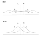
- FIG. 2B shows the horizontal resolution of the image observed by the observer when the optical system is arranged so that the image displayed on the image forming apparatus reaches the observer's pupil in a just-focus state (in-focus state).
- the simulation results are shown, but the difference and change in the horizontal resolution of the image with respect to the angle of view are large.
- the horizontal axis represents the horizontal angle of view
- the horizontal axis represents the resolution. From FIG. 2B, the horizontal resolution is the highest at an angle of view that matches the optical axis (optical principal axis) of the lens group, and the horizontal direction increases as the angle of view deviates from the angle of view that matches the optical axis (optical principal axis) of the lens group. The resolution is greatly reduced.
- the horizontal resolution in the image from the right-eye image forming apparatus and the horizontal resolution in the image from the left-eye image forming apparatus are indicated by “R”
- the optical axis of the right-eye lens group is indicated by “L”
- an image obtained from the right-eye image display device is displayed.
- the horizontal resolution is indicated by “a”
- the horizontal resolution of an image obtained from the left-eye image display device is indicated by “b”.
- FIG. 2A the observer observes when the optical system is arranged so that the image displayed on the image forming apparatus reaches the observer's pupil in a defocused state (0.4 mm, under focus).
- the result of simulating the horizontal resolution of the image is shown, but the difference / change in the horizontal resolution of the image with respect to the angle of view is small.
- the horizontal resolution in the image from the right-eye image forming apparatus and the horizontal resolution in the image from the left-eye image forming apparatus is small and there is little discomfort.
- the optical system is arranged so that the image displayed on the image forming apparatus reaches the observer's pupil in the defocused state, the observer observes. It is possible to suppress the occurrence of differences and changes in image resolution.
- the present disclosure has been described based on the preferred embodiments, the present disclosure is not limited to these embodiments.
- the configurations and structures of the image display apparatus and the image forming apparatus described in the embodiments are examples and can be changed as appropriate.
- the projector can also be configured by a combination of the image forming apparatus described in the embodiment and a support member that supports the image forming apparatus.
- a semi-transmissive mirror also referred to as a partial reflecting mirror, a partial transmitting mirror, a semi-transmissive mirror, or a half mirror
- a semi-transmissive mirror also referred to as a partial reflecting mirror, a partial transmitting mirror, a semi-transmissive mirror, or a half mirror
- this indication can also take the following structures.
- a display device comprising: The image display device (A) an image forming apparatus, and (B) an optical system for guiding an image from the image forming apparatus to the pupil of the observer; With When the direction of the image forming apparatus corresponding to the first direction of the image is the X direction and the direction of the image forming apparatus corresponding to the second direction of the image different from the first direction is the Y direction, the image forming apparatus Curved along the X direction, the Y direction, or the X direction and the Y direction, The distortion correction device is a display device that corrects an input image signal and thereby corrects distortion of an observed image.
- the display device according to [A01], wherein the distortion correction device corrects the input image signal so as to give barrel distortion or pincushion distortion to the input image signal to be corrected.
- the distortion correction device corrects at least image signals corresponding to portions located at both ends of the image forming apparatus and in the vicinity thereof, and thus at least both ends of the image forming apparatus and the vicinity thereof.
- the display device according to [A01] or [A02], which corrects distortion of an image in a portion located in the area.
- a display device comprising: The image display device (A) an image forming apparatus, and (B) an optical system for guiding an image from the image forming apparatus to the pupil of the observer; With When the direction of the image forming apparatus corresponding to the first direction of the image is the X direction and the direction of the image forming apparatus corresponding to the second direction of the image different from the first direction is the Y direction, the image forming apparatus Curved along the X direction, the Y direction, or the X direction and the Y direction, A display device in which an optical system is arranged so that an image displayed on an image forming apparatus reaches an observer's pupil in a defocused state.
- the image display apparatus further includes a support member that supports the image forming apparatus, The support surface of the support member that supports the image forming apparatus is curved along the X direction, the Y direction, or the X direction and the Y direction, and thus the image forming apparatus is curved [A01]. Thru
- the display device according to [B01], wherein the degree of curvature along the X direction of the support surface of the support member is greater than the degree of curvature along the Y direction.
- the support member includes a pressing member;
- the outer shape of the image forming apparatus is a rectangular shape,
- the outer shape of the image forming apparatus is a rectangular shape.
- the display device according to [B01] or [B02], in which an outer peripheral portion of the image forming apparatus extending along the X direction is sandwiched between support members.
- the image display device includes an image forming device / optical system distance / adjustment device that adjusts a distance between the image forming device and the optical system according to any one of [A01] to [B04].
- the display device according to [C01] further including a display control device that controls a size of the entire image from the image forming device according to a distance between the image forming device and the optical system.
- the image display device includes a pupil / optical system distance / adjustment device that adjusts a distance between the optical system and an observer's pupil, according to any one of [A01] to [C02]. Display device.
- An image display apparatus passes through a predetermined point of the image forming apparatus, an axis parallel to the X direction is an X axis, an axis passing through a predetermined point of the image forming apparatus and an axis parallel to the Y direction is a Y axis.
- the display device according to any one of [A01] to [C04], further including a moving device that moves the image forming apparatus along the X direction with respect to the optical system.
- the image display device for the left eye and the image display device for the right eye are attached to the frame, Each image display device (A) an image forming apparatus, and (B) an optical system for guiding an image from the image forming apparatus to the pupil of the observer; A display device according to any one of [A01] to [C05].
- the optical system includes a reflecting mirror that reflects an image from the image forming apparatus, and a lens group that is disposed between the observer's pupil and the reflecting mirror and into which the image reflected by the reflecting mirror is incident.
- the normal of the reflecting mirror that constitutes the optical system of the left-eye image display device and the normal of the reflecting mirror that constitutes the optical system of the right-eye image display device are opposite to the observer with respect to the reflecting mirror.
- Display device [D01] crossing in space.
- the normal of the reflecting mirror constituting the optical system of the left-eye image display device and the normal of the reflecting mirror constituting the optical system of the right-eye image display device are both the pupils of the observer and infinity
- a virtual plane including both the pupils of the observer and infinity is the xy plane, a straight line connecting both the pupils of the observer is the x axis, the optical axis of the observer's right eye is the y axis,
- the point of the reflecting mirror where the optical axis of the lens group constituting the optical system of the image display device collides with the reflecting mirror is used as the reflecting axis of the right eye reflecting mirror, and the reflecting mirror constituting the optical system of the right eye image displaying device Is arranged parallel to the xz plane, and the axis on the reflector parallel to the xy plane passing through the right-eye reflector optical axis collision point is the ⁇ axis,
- the image forming apparatus and the optical system of the image display apparatus for the left eye are parallel to the yz plane through the midpoint of the line segment connecting the pupils of both the image forming apparatus and the optical system of the image display apparatus for the right eye and the observer.
- [D05] The display device according to [D04], in which the image forming apparatus is disposed above the reflecting mirror.
- [E01] The outer shape of the image forming apparatus is rectangular.
- the lens group is composed of one lens group and three lens elements.
- the second lens has negative power
- the display device according to any one of [A01] to [E01], wherein a refractive index of a material constituting the second lens is larger than a refractive index of a material constituting the first and third lenses. .
- the display device according to [E02], wherein the first lens and the third lens have positive power.
- the display unit according to [E02] or [E03], in which the lens group includes a telecentric optical system on the reflecting mirror side.
- the image forming apparatus includes an organic electroluminescence display device.
- [E06] The display device according to any one of [A01] to [E05], wherein the frame is attached to an observer's head.
- Image display device [F02] The image display device according to [F01], in which the input image signal is corrected so as to give a pincushion distortion to the input image signal to be corrected.
- the image described in [F03] is designed to equalize the horizontal resolution of the image by arranging the optical system so that the image displayed on the image forming apparatus
Landscapes
- Physics & Mathematics (AREA)
- General Physics & Mathematics (AREA)
- Optics & Photonics (AREA)
- Engineering & Computer Science (AREA)
- Multimedia (AREA)
- Signal Processing (AREA)
- Theoretical Computer Science (AREA)
- Geometry (AREA)
- Lenses (AREA)
- Transforming Electric Information Into Light Information (AREA)
Abstract
Description
(イ)フレーム、
(ロ)フレームに取り付けられた画像表示装置、及び、
(ハ)歪み補正装置、
を備えた表示装置であって、
画像表示装置は、
(A)画像形成装置、及び、
(B)画像形成装置からの画像を観察者の瞳に導く光学系、
を備えており、
画像の第1の方向に対応した画像形成装置の方向をX方向、第1の方向と異なる画像の第2の方向に対応した画像形成装置の方向をY方向としたとき、画像形成装置は、X方向、又は、Y方向、又は、X方向及びY方向に沿って湾曲しており、
歪み補正装置は、入力される画像信号を補正し、以て、観察される画像の歪みを補正する。尚、第1の方向あるいはX方向は、最終的に観察者の瞳に到達する画像の水平方向に相当し、第2の方向あるいはY方向は、最終的に観察者の瞳に到達する画像の垂直方向に相当する形態とすることができる。X方向とY方向とは、直交している場合もあるし、直交していない場合もある。以下の説明においても同様である。 The display device according to the first aspect of the present disclosure for achieving the first object is as follows.
(I) Frame,
(B) an image display device attached to the frame; and
(C) distortion correction device,
A display device comprising:
The image display device
(A) an image forming apparatus, and
(B) an optical system for guiding an image from the image forming apparatus to the pupil of the observer;
With
When the direction of the image forming apparatus corresponding to the first direction of the image is the X direction and the direction of the image forming apparatus corresponding to the second direction of the image different from the first direction is the Y direction, the image forming apparatus Curved along the X direction, the Y direction, or the X direction and the Y direction,
The distortion correction device corrects an input image signal, thereby correcting distortion of an observed image. The first direction or the X direction corresponds to the horizontal direction of the image finally reaching the observer's pupil, and the second direction or the Y direction is the image finally reaching the observer's pupil. A form corresponding to the vertical direction can be adopted. The X direction and the Y direction may be orthogonal or may not be orthogonal. The same applies to the following description.
(イ)フレーム、及び、
(ロ)フレームに取り付けられた画像表示装置、
を備えた表示装置であって、
画像表示装置は、
(A)画像形成装置、及び、
(B)画像形成装置からの画像を観察者の瞳に導く光学系、
を備えており、
画像の第1の方向に対応した画像形成装置の方向をX方向、第1の方向と異なる画像の第2の方向に対応した画像形成装置の方向をY方向としたとき、画像形成装置は、X方向、又は、Y方向、又は、X方向及びY方向に沿って湾曲しており、
画像形成装置において表示された画像がデフォーカス状態で観察者の瞳に達するように、光学系が配置されている。 The display device according to the second aspect of the present disclosure for achieving the second object described above,
(B) Frame and
(B) an image display device attached to the frame;
A display device comprising:
The image display device
(A) an image forming apparatus, and
(B) an optical system for guiding an image from the image forming apparatus to the pupil of the observer;
With
When the direction of the image forming apparatus corresponding to the first direction of the image is the X direction and the direction of the image forming apparatus corresponding to the second direction of the image different from the first direction is the Y direction, the image forming apparatus Curved along the X direction, the Y direction, or the X direction and the Y direction,
An optical system is arranged so that an image displayed on the image forming apparatus reaches the observer's pupil in a defocused state.
1.本開示の第1の態様及び第2の態様に係る表示装置、全般に関する説明
2.実施例1(本開示の第1の態様に係る表示装置)
3.実施例2(実施例1の変形)
4.実施例3(実施例2の変形)
5.実施例4(実施例1~実施例3の変形)
6.実施例5(本開示の第2の態様に係る表示装置)、その他 Hereinafter, although this indication is explained based on an example with reference to drawings, this indication is not limited to an example and various numerical values and materials in an example are illustrations. The description will be given in the following order.
1. 1. Display device according to first and second aspects of the present disclosure, general description Example 1 (display device according to first aspect of the present disclosure)
3. Example 2 (Modification of Example 1)
4). Example 3 (Modification of Example 2)
5. Example 4 (Modification of Examples 1 to 3)
6). Example 5 (display device according to the second aspect of the present disclosure), others
以下の説明において、本開示の第1の態様に係る表示装置及び本開示の第2の態様に係る表示装置を、総称して、『本開示の表示装置等』と呼ぶ場合がある。 [Description of General Display Device According to First and Second Aspects of Present Disclosure]
In the following description, the display device according to the first aspect of the present disclosure and the display device according to the second aspect of the present disclosure may be collectively referred to as “a display device of the present disclosure”.
画像表示装置は、画像形成装置を支持する支持部材を更に備えており、
画像形成装置を支持する支持部材の支持面は、X方向、又は、Y方向、又は、X方向及びY方向に沿って湾曲しており、以て、画像形成装置は湾曲している構成とすることができる。このように、支持面がX方向及び/又はY方向に沿って湾曲した支持部材を備えることで、簡素な構成、構造に基づき画像形成装置を湾曲させることができる。尚、このような構成の表示装置を、便宜上、『本開示の第1の構成の表示装置』と呼ぶ。 In the display device and the like of the present disclosure including the various preferable forms described above,
The image display apparatus further includes a support member that supports the image forming apparatus,
The support surface of the support member that supports the image forming apparatus is curved along the X direction, the Y direction, or the X direction and the Y direction, so that the image forming apparatus is curved. be able to. Thus, by providing the support member whose support surface is curved along the X direction and / or the Y direction, the image forming apparatus can be curved based on a simple configuration and structure. Note that the display device having such a configuration is referred to as a “display device having the first configuration of the present disclosure” for convenience.
支持部材は押さえ部材を備えており、
画像形成装置の外形は矩形形状であり、
X方向に沿って延びる画像形成装置の外周部は、押さえ部材によって支持部材に対して固定されている構成とすることができる。尚、画像形成装置の外周部とは、画像形成装置の端部と画像形成装置の表示領域の端部との間の領域(所謂、額縁領域)を指す。以下においても同様である。あるいは又、
画像形成装置の外形は矩形形状であり、
X方向に沿って延びる画像形成装置の外周部は、支持部材によって挟まれている構成とすることができる。但し、これらの構成に限定するものではない。場合によっては、接着剤を用いて、画像形成装置を支持部材に固定してもよい。支持部材は、例えば、ABS樹脂等を含む各種プラスチック材料、ユニレート(登録商標、ユニチカ株式会社製)やFRPといった複合材料、カーボン繊維、アルミニウム等の金属材料、合金材料から作製すればよい。 In the display device having the first configuration of the present disclosure, the degree of curvature along the X direction of the support surface of the support member may be larger than the degree of curvature along the Y direction. That is, when the degree of curvature is represented by an average radius of curvature, the average radius of curvature along the X direction of the support surface of the support member can be smaller than the average radius of curvature along the Y direction. Furthermore, in the display device of the first configuration of the present disclosure including such a configuration,
The support member includes a pressing member,
The outer shape of the image forming apparatus is a rectangular shape,
The outer peripheral portion of the image forming apparatus extending along the X direction can be configured to be fixed to the support member by a pressing member. Note that the outer peripheral portion of the image forming apparatus refers to an area (so-called frame area) between the end of the image forming apparatus and the end of the display area of the image forming apparatus. The same applies to the following. Alternatively,
The outer shape of the image forming apparatus is a rectangular shape,
The outer peripheral portion of the image forming apparatus extending along the X direction can be sandwiched between support members. However, it is not limited to these structures. In some cases, the image forming apparatus may be fixed to the support member using an adhesive. The support member may be made of, for example, various plastic materials including ABS resin, a composite material such as Unitate (registered trademark, manufactured by Unitika Ltd.) and FRP, a metal material such as carbon fiber and aluminum, and an alloy material.
左眼用画像表示装置及び右眼用画像表示装置が、フレームに取り付けられており、
各画像表示装置は、
(A)画像形成装置、及び、
(B)画像形成装置からの画像を観察者の瞳に導く光学系、
を備えている形態とすることができる。尚、このような形態の表示装置を、便宜上、『両眼タイプの本開示の表示装置』と呼ぶ。 Furthermore, the display device of the present disclosure including the above-described preferred embodiments and configurations (the display device of the first configuration of the present disclosure, the display device of the second configuration of the present disclosure, the display device of the third configuration of the present disclosure) Including)
The image display device for the left eye and the image display device for the right eye are attached to the frame,
Each image display device
(A) an image forming apparatus, and
(B) an optical system for guiding an image from the image forming apparatus to the pupil of the observer;
It can be set as the form provided with. Note that such a display device is referred to as a “binocular display device of the present disclosure” for convenience.
光学系は、前述したとおり、画像形成装置からの画像を反射する反射鏡、及び、観察者の瞳と反射鏡との間に配置され、反射鏡によって反射された画像が入射するレンズ群から成り、
左眼用画像表示装置の光学系を構成する反射鏡の法線と右眼用画像表示装置の光学系を構成する反射鏡の法線とは、反射鏡を基準として観察者とは反対側の空間で交わっている形態とすることができる。このような形態を採用することで、2つの画像形成装置を高い設計自由度にて容易に並置することができる。そして、このような形態にあっては、左眼用画像表示装置の光学系を構成する反射鏡の法線と右眼用画像表示装置の光学系を構成する反射鏡の法線とは、観察者の両方の瞳と無限遠方とを含む仮想平面(次に述べるxy平面)よりも下方で交わっている構成とすることができる。 And in the binocular type display device of the present disclosure,
As described above, the optical system includes a reflecting mirror that reflects an image from the image forming apparatus, and a lens group that is disposed between the observer's pupil and the reflecting mirror and into which the image reflected by the reflecting mirror is incident. ,
The normal of the reflecting mirror that constitutes the optical system of the left-eye image display device and the normal of the reflecting mirror that constitutes the optical system of the right-eye image display device are opposite to the observer with respect to the reflecting mirror. It can be a form that intersects in space. By adopting such a form, two image forming apparatuses can be easily juxtaposed with a high degree of design freedom. In such a form, the normal of the reflecting mirror that constitutes the optical system of the image display apparatus for the left eye and the normal of the reflecting mirror that constitutes the optical system of the image display apparatus for the right eye It is possible to adopt a configuration in which they intersect below a virtual plane (the xy plane described below) including both the pupils of the person and infinity.
観察者の両方の瞳と無限遠方とを含む仮想平面をxy平面とし、観察者の両方の瞳を結ぶ直線をx軸(具体的には、観察者の両方の瞳を結ぶ直線であって、観察者の右眼の瞳から左眼の瞳に向かう軸線をx軸)、観察者の右眼の光軸をy軸(具体的には、x軸と直交し、レンズ群側に向かう軸線をy軸)、右眼用画像表示装置の光学系を構成するレンズ群の光軸(光学主軸)が反射鏡と衝突する反射鏡の点を『右眼用反射鏡光軸衝突点』とし、右眼用画像表示装置の光学系を構成する反射鏡がxz平面と平行に(垂直に)配置されていると想定し(図9参照)、更には、右眼用反射鏡光軸衝突点を通りxy平面と平行な反射鏡上の軸線をζ軸、右眼用反射鏡光軸衝突点を通りζ軸と直交する反射鏡上の軸線をη軸としたとき(図9参照)、
右眼用画像表示装置の光学系を構成する平面鏡は、ζ軸を中心に角度θ1=45度±5度、回転した状態であって、平面鏡の上方が観察者から離れる方向に回転した状態で配置されており(反射鏡及び軸線の回転前の状態は図10Aの一点鎖線を参照。反射鏡及び軸線の回転後の状態は図10Aの実線及び点線を参照)、且つ、η軸を中心に角度θ2=7度乃至21度、回転した状態であって、平面鏡の右端が観察者から離れる方向に回転した状態で配置されており(反射鏡及び軸線の回転前の状態は図10Bの一点鎖線を参照。反射鏡及び軸線の回転後の状態は図10Bの実線及び点線を参照)、
左眼用画像表示装置の画像形成装置及び光学系は、右眼用画像表示装置の画像形成装置及び光学系と、観察者の両方の瞳を結ぶ線分の中点を通りyz平面と平行な仮想平面に対して、鏡面対称に配置されている構成とすることができる。更には、ζ軸及びη軸に直交する軸線をξ軸としたとき、ξ軸をxy平面に射影したときの軸線ξ’軸とy軸との成す角度θ3と、角度θ1、角度θ2の関係の一例を以下の表1に示す。角度θ3は、(-x,y)象限における角度を正の値とする(図9、図10A参照)。レンズ群の光軸(光学主軸)は観察者の瞳の中心と交わることが好ましい。更には、これらの好ましい形態、構成において、画像形成装置は、前述したとおり、反射鏡の上方に配置されている形態とすることが好ましい。 And in the preferable configuration of the binocular type display device of the present disclosure, as shown in FIGS. 9, 10A, and 10B, the arrangement state of the reflecting mirrors is
A virtual plane including both the pupils of the observer and infinity is the xy plane, and a straight line connecting both the pupils of the observer is an x axis (specifically, a straight line connecting both the pupils of the observer, The axis line from the observer's right eye pupil to the left eye pupil is the x axis, and the optical axis of the observer right eye is the y axis (specifically, the axis line orthogonal to the x axis and toward the lens group side is y-axis), the point of the reflecting mirror where the optical axis (optical principal axis) of the lens group constituting the optical system of the right-eye image display device collides with the reflecting mirror is defined as the “right-eye reflecting mirror optical axis collision point”. It is assumed that the reflecting mirrors constituting the optical system of the ophthalmic image display device are arranged in parallel (perpendicularly) to the xz plane (see FIG. 9), and further pass through the optical axis collision point of the right-eye reflector. When the axis on the reflecting mirror parallel to the xy plane is the ζ axis, and the axis on the reflecting mirror that passes through the optical axis collision point for the right eye and is orthogonal to the ζ axis is the η axis (see FIG. 9),
The plane mirror constituting the optical system of the image display apparatus for the right eye is in a state of being rotated about the ζ axis by an angle θ 1 = 45 ° ± 5 °, and the plane mirror is rotated in a direction away from the observer (Refer to the alternate long and short dash line in FIG. 10A for the state before the reflecting mirror and the axis rotate. Refer to the solid line and the dotted line in FIG. 10A for the state after the reflecting mirror and the axis rotate.) The angle θ 2 = 7 degrees to 21 degrees and the right end of the plane mirror is rotated in a direction away from the observer (the state before the reflection mirror and the axis are rotated is shown in FIG. 10B). (Refer to the alternate long and short dash line. See the solid and dotted lines in FIG.
The image forming apparatus and the optical system of the image display apparatus for the left eye are parallel to the yz plane through the midpoint of the line segment connecting the pupils of both the image forming apparatus and the optical system of the image display apparatus for the right eye and the observer. It can be set as the structure arrange | positioned mirror-symmetrically with respect to a virtual plane. Furthermore, when the axis perpendicular to the ζ axis and the η axis is the ξ axis, the angle θ 3 formed by the axis ξ ′ axis and the y axis when the ξ axis is projected onto the xy plane, the angle θ 1 , the angle θ An example of the relationship of 2 is shown in Table 1 below. The angle θ 3 has a positive value in the (−x, y) quadrant (see FIGS. 9 and 10A). The optical axis (optical principal axis) of the lens group preferably intersects the center of the observer's pupil. Furthermore, in these preferable forms and configurations, the image forming apparatus is preferably arranged above the reflecting mirror as described above.
θ1(度) θ2(度) θ3(度)
45 5 9
45 10 15
45 15 22
45 18 25
45 20 29 [Table 1]
θ1 (degree) θ2 (degree) θ3 (degree)
45 5 9
45 10 15
45 15 22
45 18 25
45 20 29
画像形成装置の外形は矩形形状であり、
Y方向に沿って延びる画像形成装置の外周部から配線が外部に延びている形態とすることができる。ここで、配線として、フレキシブルプリント配線板(FPC)を例示することができる。画像形成装置の外周部に設けられた接続部と配線とは、周知の方法に基づき接続すればよい。 The display device of the present disclosure including the various preferable modes and configurations described above (the display device of the first configuration of the present disclosure, the display device of the second configuration of the present disclosure, the display of the third configuration of the present disclosure) Device, including a binocular type display device of the present disclosure, and the same applies hereinafter)
The outer shape of the image forming apparatus is a rectangular shape,
The wiring may extend to the outside from the outer periphery of the image forming apparatus extending along the Y direction. Here, a flexible printed wiring board (FPC) can be illustrated as wiring. The connection portion and the wiring provided on the outer peripheral portion of the image forming apparatus may be connected based on a known method.
ディオプター値 円筒の側面の半径
-3 59mm
-2 68mm
-1 80mm
0 100mm [Table 2]
Diopter value Cylinder side radius-359mm
-2 68mm
-1 80mm
0 100mm
(イ)フレーム20、及び、
(ロ)フレーム20に取り付けられた画像表示装置30、
を備えている。そして、画像表示装置30は、
(A)画像形成装置40、及び、
(B)画像形成装置40からの画像を観察者10の瞳11に導く光学系50、
を備えている。また、実施例1の表示装置は、更に、
(ハ)歪み補正装置、
を備えている。尚、実施例1あるいは後述する実施例5の表示装置は、より具体的には、両眼タイプの本開示の表示装置であり、
左眼用画像表示装置30L及び右眼用画像表示装置30Rが、フレーム20に取り付けられており、
各画像表示装置30L,30Rは、
(A)画像形成装置40L,40R、及び、
(B)画像形成装置40L,40Rからの画像を観察者10の瞳11(11L,11R)に導く光学系50、
を備えている。実施例1あるいは後述する実施例5の表示装置におけるフレーム20は観察者10の頭部に装着され、実施例1あるいは後述する実施例5の表示装置は、より具体的には、頭部装着型ディスプレイ(HMD)である。 The display device of Example 1 or Example 5 to be described later is
(A)
(B) an
It has. The
(A) the
(B) an
It has. Further, the display device of Example 1 further includes:
(C) distortion correction device,
It has. The display device of Example 1 or Example 5 described later is more specifically a display device of the present disclosure of a binocular type,
The left-eye
Each of the
(A)
(B) an
It has. The
円筒の側面の半径(mm) レンズ群52の有効焦点距離(mm)
50 28
100 56
146 67.2
238 95 [Table 3]
Radius of side surface of cylinder (mm) Effective focal length of lens group 52 (mm)
50 28
100 56
146 67.2
238 95
支持部材601は押さえ部材65を備えており、
画像形成装置40の外形は、前述したとおり、矩形形状であり、
X方向に沿って延びる画像形成装置40の外周部は、押さえ部材65によって支持部材601に対して固定されている。 And in the
Support member 60 1 is provided with a pressing
As described above, the outer shape of the
The outer peripheral portion of the
角度θ1=45度
角度θ2=10度
角度θ3=15度
とした。尚、実施例において、反射鏡光軸衝突点はxy平面内に含まれている。このような設定条件では、左眼用画像表示装置30Lを構成する画像形成装置40と、右眼用画像表示装置30Rを構成する画像形成装置40との間に、約15mmの隙間が存在し、2つの画像形成装置を並置することができる。また、画像形成装置40の表示領域の長さLXを126mm、
角度θ1=45度
角度θ2=18度
角度θ3=25度
とすれば、左眼用画像表示装置30Lを構成する画像形成装置40と、右眼用画像表示装置30Rを構成する画像形成装置40との間に、約15mmの隙間が存在し、2つの画像形成装置を並置することができる。 As described above, the
Angle θ 1 = 45 degrees Angle θ 2 = 10 degrees Angle θ 3 = 15 degrees. In the embodiment, the reflecting mirror optical axis collision point is included in the xy plane. Under such setting conditions, there is a gap of about 15 mm between the
If the angle θ 1 = 45 degrees, the angle θ 2 = 18 degrees, and the angle θ 3 = 25 degrees, the
角度θ1=45度
角度θ2= 0度
角度θ3= 0度
とした場合であって、X方向に沿った各画像形成装置40の表示領域の長さLXを100mm、観察者の左眼の光軸と右眼の光軸との間の距離を65mmとした場合、左眼用画像表示装置30Lを構成する画像形成装置40と、右眼用画像表示装置30Rを構成する画像形成装置40とは、約35mm[=50+50-65(mm)]、重なり合い、2つの画像形成装置を並置することができない。 If,
In this case, the angle θ 1 = 45 degrees, the angle θ 2 = 0, the angle θ 3 = 0, and the length L X of the display area of each
第1番目のレンズ 第2番目のレンズ 第3番目のレンズ
屈折率 1.740 2.017 1.740
アッベ数 44.8438 20.830 44.8438
有効焦点距離 27.392mm -43.604mm 150.185mm
後側焦点距離 28.101mm -45.387mm 146.790mm
前側焦点距離 -11.141mm 52.856mm -124.868mm
Fナンバー 6.8480 -10.9010 37.5463 [Table 4]
First lens Second lens Third lens refractive index 1.740 2.017 1.740
Abbe number 44.8438 20.830 44.8438
Effective focal length 27.392mm -43.604mm 150.185mm
Rear focal length 28.101mm -45.387mm 146.790mm
Front focal length -11.141mm 52.856mm -124.868mm
F number 6.8480 -10.010 37.5463
ディオプター値 移動量 絵だしサイズ
-3 -9.4mm 95.5mm
-2 -6.3mm 97.8mm
-1 -3.1mm 100.3mm
0 0 103.4mm
1 +3.1mm 106.7mm
2 +6.3mm 110.0mm
3 +9.4mm 113.8mm [Table 5]
Diopter value Movement amount Picture size-3 -9.4mm 95.5mm
-2 -6.3mm 97.8mm
-1 -3.1mm 100.3mm
0 0 103.4mm
1 + 3.1mm 106.7mm
2 + 6.3mm 110.0mm
3 + 9.4mm 113.8mm
[A01]《表示装置:第1の態様》
(イ)フレーム、
(ロ)フレームに取り付けられた画像表示装置、及び、
(ハ)歪み補正装置、
を備えた表示装置であって、
画像表示装置は、
(A)画像形成装置、及び、
(B)画像形成装置からの画像を観察者の瞳に導く光学系、
を備えており、
画像の第1の方向に対応した画像形成装置の方向をX方向、第1の方向と異なる画像の第2の方向に対応した画像形成装置の方向をY方向としたとき、画像形成装置は、X方向、又は、Y方向、又は、X方向及びY方向に沿って湾曲しており、
歪み補正装置は、入力される画像信号を補正し、以て、観察される画像の歪みを補正する表示装置。
[A02]歪み補正装置は、補正すべき入力される画像信号に対して樽型歪み又は糸巻き型歪みを与えるように、入力される画像信号を補正する[A01]に記載の表示装置。
[A03]歪み補正装置は、少なくとも入力される画像信号の内、画像形成装置の両端及びその近傍に位置する部分に対応する画像信号を補正し、以て、少なくとも画像形成装置の両端及びその近傍に位置する部分における画像の歪みを補正する[A01]又は[A02]に記載の表示装置。
[A04]《表示装置:第2の態様》
(イ)フレーム、及び、
(ロ)フレームに取り付けられた画像表示装置、
を備えた表示装置であって、
画像表示装置は、
(A)画像形成装置、及び、
(B)画像形成装置からの画像を観察者の瞳に導く光学系、
を備えており、
画像の第1の方向に対応した画像形成装置の方向をX方向、第1の方向と異なる画像の第2の方向に対応した画像形成装置の方向をY方向としたとき、画像形成装置は、X方向、又は、Y方向、又は、X方向及びY方向に沿って湾曲しており、
画像形成装置において表示された画像がデフォーカス状態で観察者の瞳に達するように、光学系が配置されている表示装置。
[A05]画像形成装置において表示された画像がデフォーカス状態で観察者の瞳に達するように光学系が配置されることで、画像の水平方向解像度の均一化を図る[A04]に記載の表示装置。
[B01]画像表示装置は、画像形成装置を支持する支持部材を更に備えており、
画像形成装置を支持する支持部材の支持面は、X方向、又は、Y方向、又は、X方向及びY方向に沿って湾曲しており、以て、画像形成装置は湾曲している[A01]乃至[A05]のいずれか1項に記載の表示装置。
[B02]支持部材の支持面のX方向に沿った湾曲の度合いは、Y方向に沿った湾曲の度合いよりも大きい[B01]に記載の表示装置。
[B03]支持部材は押さえ部材を備えており、
画像形成装置の外形は矩形形状であり、
X方向に沿って延びる画像形成装置の外周部は、押さえ部材によって支持部材に対して固定されている[B01]又は[B02]に記載の表示装置。
[B04]画像形成装置の外形は矩形形状であり、
X方向に沿って延びる画像形成装置の外周部は、支持部材によって挟まれている[B01]又は[B02]に記載の表示装置。
[C01]画像表示装置は、画像形成装置と光学系との間の距離を調整する画像形成装置/光学系間距離・調整装置を備えている[A01]乃至[B04]のいずれか1項に記載の表示装置。
[C02]画像形成装置と光学系との間の距離に応じて、画像形成装置からの画像全体の大きさを制御する表示制御装置を更に備えている[C01]に記載の表示装置。
[C03]画像表示装置は、光学系と観察者の瞳との間の距離を調整する瞳/光学系間距離・調整装置を備えている[A01]乃至[C02]のいずれか1項に記載の表示装置。
[C04]画像形成装置の所定の点を通り、X方向に平行な軸をX軸、画像形成装置の所定の点を通り、Y方向に平行な軸をY軸としたとき、画像表示装置は、X軸、Y軸及びZ軸の内の少なくとも1つの軸を中心に画像形成装置を回動させる回動装置を更に備えている[A01]乃至[C03]のいずれか1項に記載の表示装置。
[C05]光学系に対して画像形成装置をX方向に沿って移動させる移動装置を更に備えている[A01]乃至[C04]のいずれか1項に記載の表示装置。
[D01]左眼用画像表示装置及び右眼用画像表示装置が、フレームに取り付けられており、
各画像表示装置は、
(A)画像形成装置、及び、
(B)画像形成装置からの画像を観察者の瞳に導く光学系、
を備えている[A01]乃至[C05]のいずれか1項に表示装置。
[D02]光学系は、画像形成装置からの画像を反射する反射鏡、及び、観察者の瞳と反射鏡との間に配置され、反射鏡によって反射された画像が入射するレンズ群から成り、
左眼用画像表示装置の光学系を構成する反射鏡の法線と右眼用画像表示装置の光学系を構成する反射鏡の法線とは、反射鏡を基準として観察者とは反対側の空間で交わっている[D01]に表示装置。
[D03]左眼用画像表示装置の光学系を構成する反射鏡の法線と右眼用画像表示装置の光学系を構成する反射鏡の法線とは、観察者の両方の瞳と無限遠方とを含む仮想平面よりも下方で交わっている[D02]に記載の表示装置。
[D04]観察者の両方の瞳と無限遠方とを含む仮想平面をxy平面とし、観察者の両方の瞳を結ぶ直線をx軸、観察者の右眼の光軸をy軸、右眼用画像表示装置の光学系を構成するレンズ群の光軸が反射鏡と衝突する反射鏡の点を右眼用反射鏡光軸衝突点とし、右眼用画像表示装置の光学系を構成する反射鏡がxz平面と平行に配置されていると想定し、更には、右眼用反射鏡光軸衝突点を通りxy平面と平行な反射鏡上の軸線をζ軸、右眼用反射鏡光軸衝突点を通りζ軸と直交する反射鏡上の軸線をη軸としたとき、
右眼用画像表示装置の光学系を構成する平面鏡は、ζ軸を中心に角度θ1=45度±5度、回転した状態であって、平面鏡の上方が観察者から離れる方向に回転した状態で配置されており、且つ、η軸を中心に角度θ2=7度乃至21度、回転した状態であって、平面鏡の右端が観察者から離れる方向に回転した状態で配置されており、
左眼用画像表示装置の画像形成装置及び光学系は、右眼用画像表示装置の画像形成装置及び光学系と、観察者の両方の瞳を結ぶ線分の中点を通りyz平面と平行な仮想平面に対して、鏡面対称に配置されている[D03]に記載の表示装置。
「D05]画像形成装置は、反射鏡の上方に配置されている[D04]に記載の表示装置。
[D06]左眼用画像表示装置と右眼用画像表示装置との間の距離を調整する画像表示装置間距離・調整装置を更に備えている[D01]乃至[D05]のいずれか1項に記載の表示装置。
[E01]画像形成装置の外形は矩形形状であり、
Y方向に沿って延びる画像形成装置の外周部から配線が外部に延びている[A01]乃至[D05]のいずれか1項に記載の表示装置。
[E02]レンズ群は、1群、3枚のレンズから成り、
第2番目のレンズは、負のパワーを有し、
第2番目のレンズを構成する材料の屈折率は、第1番目及び第3番目のレンズを構成する材料の屈折率よりも大きい[A01]乃至[E01]のいずれか1項に記載の表示装置。
[E03]第1番目のレンズ及び第3番目のレンズは、正のパワーを有する[E02]に記載の表示装置。
[E04]レンズ群は、反射鏡側がテレセントリック光学系である[E02]又は[E03]に記載の表示装置。
[E05]画像形成装置は有機エレクトロルミネッセンス表示装置から成る[A01]乃至[E04]のいずれか1項に記載の表示装置。
[E06]フレームは観察者の頭部に装着される[A01]乃至[E05]のいずれか1項に記載の表示装置。
[F01]《画像表示装置:第1の態様》
(A)画像形成装置、及び、
(B)画像形成装置からの画像を観察者の瞳に導く光学系、
を備えており、
画像の第1の方向に対応した画像形成装置の方向をX方向、第1の方向と異なる画像の第2の方向に対応した画像形成装置の方向をY方向としたとき、画像形成装置は、X方向、又は、Y方向、又は、X方向及びY方向に沿って湾曲しており、
入力される画像信号の内、画像形成装置の両端及びその近傍に位置する部分に対応する画像信号が補正され、以て、画像形成装置の両端及びその近傍に位置する部分における画像の歪みが補正される画像表示装置。
[F02]補正すべき入力される画像信号に対して糸巻き型歪みを与えるように、入力される画像信号が補正される[F01]に記載の画像表示装置。
[F03]《画像表示装置:第2の態様》
(A)画像形成装置、及び、
(B)画像形成装置からの画像を観察者の瞳に導く光学系、
を備えており、
画像の第1の方向に対応した画像形成装置の方向をX方向、第1の方向と異なる画像の第2の方向に対応した画像形成装置の方向をY方向としたとき、画像形成装置は、X方向、又は、Y方向、又は、X方向及びY方向に沿って湾曲しており、
画像形成装置において表示された画像がデフォーカス状態で観察者の瞳に達するように、光学系が配置されている画像表示装置。
[F04]画像形成装置において表示された画像がデフォーカス状態で観察者の瞳に達するように光学系が配置されることで、画像の水平方向解像度の均一化を図る[F03]に記載の画像表示装置。 In addition, this indication can also take the following structures.
[A01] << Display device: first aspect >>
(I) Frame,
(B) an image display device attached to the frame; and
(C) distortion correction device,
A display device comprising:
The image display device
(A) an image forming apparatus, and
(B) an optical system for guiding an image from the image forming apparatus to the pupil of the observer;
With
When the direction of the image forming apparatus corresponding to the first direction of the image is the X direction and the direction of the image forming apparatus corresponding to the second direction of the image different from the first direction is the Y direction, the image forming apparatus Curved along the X direction, the Y direction, or the X direction and the Y direction,
The distortion correction device is a display device that corrects an input image signal and thereby corrects distortion of an observed image.
[A02] The display device according to [A01], wherein the distortion correction device corrects the input image signal so as to give barrel distortion or pincushion distortion to the input image signal to be corrected.
[A03] The distortion correction device corrects at least image signals corresponding to portions located at both ends of the image forming apparatus and in the vicinity thereof, and thus at least both ends of the image forming apparatus and the vicinity thereof. The display device according to [A01] or [A02], which corrects distortion of an image in a portion located in the area.
[A04] << Display device: second aspect >>
(B) Frame and
(B) an image display device attached to the frame;
A display device comprising:
The image display device
(A) an image forming apparatus, and
(B) an optical system for guiding an image from the image forming apparatus to the pupil of the observer;
With
When the direction of the image forming apparatus corresponding to the first direction of the image is the X direction and the direction of the image forming apparatus corresponding to the second direction of the image different from the first direction is the Y direction, the image forming apparatus Curved along the X direction, the Y direction, or the X direction and the Y direction,
A display device in which an optical system is arranged so that an image displayed on an image forming apparatus reaches an observer's pupil in a defocused state.
[A05] The display according to [A04], in which the optical system is arranged so that the image displayed on the image forming apparatus reaches the observer's pupil in a defocused state, thereby achieving uniform horizontal resolution of the image. apparatus.
[B01] The image display apparatus further includes a support member that supports the image forming apparatus,
The support surface of the support member that supports the image forming apparatus is curved along the X direction, the Y direction, or the X direction and the Y direction, and thus the image forming apparatus is curved [A01]. Thru | or the display apparatus of any one of [A05].
[B02] The display device according to [B01], wherein the degree of curvature along the X direction of the support surface of the support member is greater than the degree of curvature along the Y direction.
[B03] The support member includes a pressing member;
The outer shape of the image forming apparatus is a rectangular shape,
The display device according to [B01] or [B02], in which an outer peripheral portion of the image forming apparatus extending along the X direction is fixed to a support member by a pressing member.
[B04] The outer shape of the image forming apparatus is a rectangular shape.
The display device according to [B01] or [B02], in which an outer peripheral portion of the image forming apparatus extending along the X direction is sandwiched between support members.
[C01] The image display device includes an image forming device / optical system distance / adjustment device that adjusts a distance between the image forming device and the optical system according to any one of [A01] to [B04]. The display device described.
[C02] The display device according to [C01], further including a display control device that controls a size of the entire image from the image forming device according to a distance between the image forming device and the optical system.
[C03] The image display device includes a pupil / optical system distance / adjustment device that adjusts a distance between the optical system and an observer's pupil, according to any one of [A01] to [C02]. Display device.
[C04] An image display apparatus passes through a predetermined point of the image forming apparatus, an axis parallel to the X direction is an X axis, an axis passing through a predetermined point of the image forming apparatus and an axis parallel to the Y direction is a Y axis. The display according to any one of [A01] to [C03], further including a rotation device that rotates the image forming apparatus about at least one of the X, Y, and Z axes. apparatus.
[C05] The display device according to any one of [A01] to [C04], further including a moving device that moves the image forming apparatus along the X direction with respect to the optical system.
[D01] The image display device for the left eye and the image display device for the right eye are attached to the frame,
Each image display device
(A) an image forming apparatus, and
(B) an optical system for guiding an image from the image forming apparatus to the pupil of the observer;
A display device according to any one of [A01] to [C05].
[D02] The optical system includes a reflecting mirror that reflects an image from the image forming apparatus, and a lens group that is disposed between the observer's pupil and the reflecting mirror and into which the image reflected by the reflecting mirror is incident.
The normal of the reflecting mirror that constitutes the optical system of the left-eye image display device and the normal of the reflecting mirror that constitutes the optical system of the right-eye image display device are opposite to the observer with respect to the reflecting mirror. Display device [D01] crossing in space.
[D03] The normal of the reflecting mirror constituting the optical system of the left-eye image display device and the normal of the reflecting mirror constituting the optical system of the right-eye image display device are both the pupils of the observer and infinity The display device according to [D02], which intersects below a virtual plane including:
[D04] A virtual plane including both the pupils of the observer and infinity is the xy plane, a straight line connecting both the pupils of the observer is the x axis, the optical axis of the observer's right eye is the y axis, The point of the reflecting mirror where the optical axis of the lens group constituting the optical system of the image display device collides with the reflecting mirror is used as the reflecting axis of the right eye reflecting mirror, and the reflecting mirror constituting the optical system of the right eye image displaying device Is arranged parallel to the xz plane, and the axis on the reflector parallel to the xy plane passing through the right-eye reflector optical axis collision point is the ζ axis, and the right-eye reflector optical axis collision is assumed. When the axis on the reflector passing through the point and perpendicular to the ζ axis is the η axis,
The plane mirror constituting the optical system of the image display apparatus for the right eye is in a state of being rotated about the ζ axis by an angle θ 1 = 45 ° ± 5 °, and the plane mirror is rotated in a direction away from the observer And is rotated with the angle θ 2 = 7 to 21 degrees around the η axis, with the right end of the plane mirror being rotated away from the observer,
The image forming apparatus and the optical system of the image display apparatus for the left eye are parallel to the yz plane through the midpoint of the line segment connecting the pupils of both the image forming apparatus and the optical system of the image display apparatus for the right eye and the observer. The display device according to [D03], which is arranged mirror-symmetrically with respect to the virtual plane.
[D05] The display device according to [D04], in which the image forming apparatus is disposed above the reflecting mirror.
[D06] Any one of [D01] to [D05], further including an inter-image display device distance adjustment device that adjusts a distance between the left-eye image display device and the right-eye image display device. The display device described.
[E01] The outer shape of the image forming apparatus is rectangular.
The display device according to any one of [A01] to [D05], wherein a wiring extends to the outside from an outer peripheral portion of the image forming apparatus extending along the Y direction.
[E02] The lens group is composed of one lens group and three lens elements.
The second lens has negative power,
The display device according to any one of [A01] to [E01], wherein a refractive index of a material constituting the second lens is larger than a refractive index of a material constituting the first and third lenses. .
[E03] The display device according to [E02], wherein the first lens and the third lens have positive power.
[E04] The display unit according to [E02] or [E03], in which the lens group includes a telecentric optical system on the reflecting mirror side.
[E05] The display device according to any one of [A01] to [E04], in which the image forming apparatus includes an organic electroluminescence display device.
[E06] The display device according to any one of [A01] to [E05], wherein the frame is attached to an observer's head.
[F01] << Image display device: first aspect >>
(A) an image forming apparatus, and
(B) an optical system for guiding an image from the image forming apparatus to the pupil of the observer;
With
When the direction of the image forming apparatus corresponding to the first direction of the image is the X direction and the direction of the image forming apparatus corresponding to the second direction of the image different from the first direction is the Y direction, the image forming apparatus Curved along the X direction, the Y direction, or the X direction and the Y direction,
Among the input image signals, the image signals corresponding to the portions located at both ends of the image forming apparatus and the vicinity thereof are corrected, so that the image distortion at the portions positioned at both ends of the image forming apparatus and the vicinity thereof is corrected. Image display device.
[F02] The image display device according to [F01], in which the input image signal is corrected so as to give a pincushion distortion to the input image signal to be corrected.
[F03] << Image display device: second aspect >>
(A) an image forming apparatus, and
(B) an optical system for guiding an image from the image forming apparatus to the pupil of the observer;
With
When the direction of the image forming apparatus corresponding to the first direction of the image is the X direction and the direction of the image forming apparatus corresponding to the second direction of the image different from the first direction is the Y direction, the image forming apparatus Curved along the X direction, the Y direction, or the X direction and the Y direction,
An image display device in which an optical system is arranged so that an image displayed on the image forming device reaches an observer's pupil in a defocused state.
[F04] The image described in [F03] is designed to equalize the horizontal resolution of the image by arranging the optical system so that the image displayed on the image forming apparatus reaches the observer's pupil in a defocused state. Display device.
Claims (20)
- (イ)フレーム、
(ロ)フレームに取り付けられた画像表示装置、及び、
(ハ)歪み補正装置、
を備えた表示装置であって、
画像表示装置は、
(A)画像形成装置、及び、
(B)画像形成装置からの画像を観察者の瞳に導く光学系、
を備えており、
画像の第1の方向に対応した画像形成装置の方向をX方向、第1の方向と異なる画像の第2の方向に対応した画像形成装置の方向をY方向としたとき、画像形成装置は、X方向、又は、Y方向、又は、X方向及びY方向に沿って湾曲しており、
歪み補正装置は、入力される画像信号を補正し、以て、観察される画像の歪みを補正する表示装置。 (I) Frame,
(B) an image display device attached to the frame; and
(C) distortion correction device,
A display device comprising:
The image display device
(A) an image forming apparatus, and
(B) an optical system for guiding an image from the image forming apparatus to the pupil of the observer;
With
When the direction of the image forming apparatus corresponding to the first direction of the image is the X direction and the direction of the image forming apparatus corresponding to the second direction of the image different from the first direction is the Y direction, the image forming apparatus Curved along the X direction, the Y direction, or the X direction and the Y direction,
The distortion correction device is a display device that corrects an input image signal and thereby corrects distortion of an observed image. - 歪み補正装置は、補正すべき入力される画像信号に対して樽型歪み又は糸巻き型歪みを与えるように、入力される画像信号を補正する請求項1に記載の表示装置。 The display device according to claim 1, wherein the distortion correction device corrects the input image signal so as to give barrel distortion or pincushion distortion to the input image signal to be corrected.
- 歪み補正装置は、入力される画像信号の内、少なくとも画像形成装置の両端及びその近傍に位置する部分に対応する画像信号を補正し、以て、少なくとも画像形成装置の両端及びその近傍に位置する部分における画像の歪みを補正する請求項1に記載の表示装置。 The distortion correction device corrects image signals corresponding to at least portions of the input image signal located at both ends and the vicinity thereof, and is thus positioned at least at both ends of the image formation device and the vicinity thereof. The display device according to claim 1, wherein image distortion in the portion is corrected.
- (イ)フレーム、及び、
(ロ)フレームに取り付けられた画像表示装置、
を備えた表示装置であって、
画像表示装置は、
(A)画像形成装置、及び、
(B)画像形成装置からの画像を観察者の瞳に導く光学系、
を備えており、
画像の第1の方向に対応した画像形成装置の方向をX方向、第1の方向と異なる画像の第2の方向に対応した画像形成装置の方向をY方向としたとき、画像形成装置は、X方向、又は、Y方向、又は、X方向及びY方向に沿って湾曲しており、
画像形成装置において表示された画像がデフォーカス状態で観察者の瞳に達するように、光学系が配置されている表示装置。 (B) Frame and
(B) an image display device attached to the frame;
A display device comprising:
The image display device
(A) an image forming apparatus, and
(B) an optical system for guiding an image from the image forming apparatus to the pupil of the observer;
With
When the direction of the image forming apparatus corresponding to the first direction of the image is the X direction and the direction of the image forming apparatus corresponding to the second direction of the image different from the first direction is the Y direction, the image forming apparatus Curved along the X direction, the Y direction, or the X direction and the Y direction,
A display device in which an optical system is arranged so that an image displayed on an image forming apparatus reaches an observer's pupil in a defocused state. - 画像形成装置において表示された画像がデフォーカス状態で観察者の瞳に達するように光学系が配置されることで、画像の水平方向解像度の均一化を図る請求項4に記載の表示装置。 The display device according to claim 4, wherein the horizontal resolution of the image is made uniform by arranging an optical system so that the image displayed on the image forming device reaches the pupil of the observer in a defocused state.
- 画像表示装置は、画像形成装置を支持する支持部材を更に備えており、
画像形成装置を支持する支持部材の支持面は、X方向、又は、Y方向、又は、X方向及びY方向に沿って湾曲しており、以て、画像形成装置は湾曲している請求項1又は請求項4に記載の表示装置。 The image display apparatus further includes a support member that supports the image forming apparatus,
The support surface of the support member that supports the image forming apparatus is curved along the X direction, the Y direction, or the X direction and the Y direction, and thus the image forming apparatus is curved. Or the display apparatus of Claim 4. - 支持部材は押さえ部材を備えており、
画像形成装置の外形は矩形形状であり、
X方向に沿って延びる画像形成装置の外周部は、押さえ部材によって支持部材に対して固定されている請求項6に記載の表示装置。 The support member includes a pressing member,
The outer shape of the image forming apparatus is a rectangular shape,
The display device according to claim 6, wherein an outer peripheral portion of the image forming apparatus extending along the X direction is fixed to a support member by a pressing member. - 画像形成装置の外形は矩形形状であり、
X方向に沿って延びる画像形成装置の外周部は、支持部材によって挟まれている請求項6に記載の表示装置。 The outer shape of the image forming apparatus is a rectangular shape,
The display device according to claim 6, wherein an outer peripheral portion of the image forming apparatus extending along the X direction is sandwiched between support members. - 画像表示装置は、画像形成装置と光学系との間の距離を調整する画像形成装置/光学系間距離・調整装置を備えている請求項1又は請求項4に記載の表示装置。 5. The display device according to claim 1, wherein the image display device includes an image forming device / optical system distance / adjusting device for adjusting a distance between the image forming device and the optical system.
- 画像形成装置と光学系との間の距離に応じて、画像形成装置からの画像全体の大きさを制御する表示制御装置を更に備えている請求項9に記載の表示装置。 The display device according to claim 9, further comprising a display control device that controls a size of the entire image from the image forming device in accordance with a distance between the image forming device and the optical system.
- 画像表示装置は、光学系と観察者の瞳との間の距離を調整する瞳/光学系間距離・調整装置を備えている請求項1又は請求項4に記載の表示装置。 5. The display device according to claim 1, wherein the image display device includes a pupil / optical system distance / adjustment device that adjusts a distance between the optical system and an observer's pupil.
- 画像形成装置の所定の点を通り、X方向に平行な軸をX軸、画像形成装置の所定の点を通り、Y方向に平行な軸をY軸としたとき、画像表示装置は、X軸、Y軸及びZ軸の内の少なくとも1つの軸を中心に画像形成装置を回動させる回動装置を更に備えている請求項1又は請求項4に記載の表示装置。 An image display device is configured to pass through a predetermined point of the image forming apparatus and the axis parallel to the X direction is the X axis, and an axis passing through the predetermined point of the image forming apparatus and parallel to the Y direction is the Y axis. The display device according to claim 1, further comprising a rotation device that rotates the image forming apparatus about at least one of the Y axis and the Z axis.
- 光学系に対して画像形成装置をX方向に沿って移動させる移動装置を更に備えている請求項1又は請求項4に記載の表示装置。 The display device according to claim 1, further comprising a moving device that moves the image forming apparatus along the X direction with respect to the optical system.
- 左眼用画像表示装置及び右眼用画像表示装置が、フレームに取り付けられており、
各画像表示装置は、
(A)画像形成装置、及び、
(B)画像形成装置からの画像を観察者の瞳に導く光学系、
を備えている請求項1又は請求項4に表示装置。 The image display device for the left eye and the image display device for the right eye are attached to the frame,
Each image display device
(A) an image forming apparatus, and
(B) an optical system for guiding an image from the image forming apparatus to the pupil of the observer;
The display device according to claim 1 or claim 4, further comprising: - 光学系は、画像形成装置からの画像を反射する反射鏡、及び、観察者の瞳と反射鏡との間に配置され、反射鏡によって反射された画像が入射するレンズ群から成り、
左眼用画像表示装置の光学系を構成する反射鏡の法線と右眼用画像表示装置の光学系を構成する反射鏡の法線とは、反射鏡を基準として観察者とは反対側の空間で交わっている請求項14に表示装置。 The optical system includes a reflecting mirror that reflects an image from the image forming apparatus, and a lens group that is arranged between the observer's pupil and the reflecting mirror and into which the image reflected by the reflecting mirror is incident.
The normal of the reflecting mirror that constitutes the optical system of the left-eye image display device and the normal of the reflecting mirror that constitutes the optical system of the right-eye image display device are opposite to the observer with respect to the reflecting mirror. The display device according to claim 14, which intersects in space. - 左眼用画像表示装置の光学系を構成する反射鏡の法線と右眼用画像表示装置の光学系を構成する反射鏡の法線とは、観察者の両方の瞳と無限遠方とを含む仮想平面よりも下方で交わっている請求項15に記載の表示装置。 The normal of the reflector constituting the optical system of the left-eye image display device and the normal of the reflector constituting the optical system of the right-eye image display device include both the pupils of the observer and infinity. The display device according to claim 15, which intersects below the virtual plane.
- 観察者の両方の瞳と無限遠方とを含む仮想平面をxy平面とし、観察者の両方の瞳を結ぶ直線をx軸、観察者の右眼の光軸をy軸、右眼用画像表示装置の光学系を構成するレンズ群の光軸が反射鏡と衝突する反射鏡の点を右眼用反射鏡光軸衝突点とし、右眼用画像表示装置の光学系を構成する反射鏡がxz平面と平行に配置されていると想定し、更には、右眼用反射鏡光軸衝突点を通りxy平面と平行な反射鏡上の軸線をζ軸、右眼用反射鏡光軸衝突点を通りζ軸と直交する反射鏡上の軸線をη軸としたとき、
右眼用画像表示装置の光学系を構成する平面鏡は、ζ軸を中心に角度θ1=45度±5度、回転した状態であって、平面鏡の上方が観察者から離れる方向に回転した状態で配置されており、且つ、η軸を中心に角度θ2=7度乃至21度、回転した状態であって、平面鏡の右端が観察者から離れる方向に回転した状態で配置されており、
左眼用画像表示装置の画像形成装置及び光学系は、右眼用画像表示装置の画像形成装置及び光学系と、観察者の両方の瞳を結ぶ線分の中点を通りyz平面と平行な仮想平面に対して、鏡面対称に配置されている請求項16に記載の表示装置。 A virtual plane including both the pupils of the observer and infinity is the xy plane, the straight line connecting both the pupils of the observer is the x axis, the optical axis of the right eye of the observer is the y axis, and the right eye image display device The point of the reflecting mirror where the optical axis of the lens group that constitutes the optical system collides with the reflecting mirror is taken as the reflecting axis of the reflecting eye for the right eye, and the reflecting mirror that constitutes the optical system of the right-eye image display device Furthermore, the axis on the reflector parallel to the xy plane passes through the ζ axis and passes through the reflector optical axis collision point for the right eye. When the axis on the reflector perpendicular to the ζ axis is the η axis,
The plane mirror constituting the optical system of the image display apparatus for the right eye is in a state of being rotated about the ζ axis by an angle θ 1 = 45 ° ± 5 °, and the plane mirror is rotated in a direction away from the observer And is rotated with the angle θ 2 = 7 to 21 degrees around the η axis, with the right end of the plane mirror being rotated away from the observer,
The image forming apparatus and the optical system of the image display apparatus for the left eye are parallel to the yz plane through the midpoint of the line segment connecting the pupils of both the image forming apparatus and the optical system of the image display apparatus for the right eye and the observer. The display device according to claim 16, wherein the display device is arranged in mirror symmetry with respect to a virtual plane. - 画像形成装置は、反射鏡の上方に配置されている請求項17に記載の表示装置。 The display device according to claim 17, wherein the image forming apparatus is disposed above the reflecting mirror.
- 左眼用画像表示装置と右眼用画像表示装置との間の距離を調整する画像表示装置間距離・調整装置を更に備えている請求項14に記載の表示装置。 The display device according to claim 14, further comprising a distance / adjustment device between image display devices for adjusting a distance between the image display device for the left eye and the image display device for the right eye.
- 画像形成装置は有機エレクトロルミネッセンス表示装置から成る請求項1又は請求項4に記載の表示装置。 5. The display device according to claim 1 or 4, wherein the image forming apparatus comprises an organic electroluminescence display device.
Priority Applications (6)
| Application Number | Priority Date | Filing Date | Title |
|---|---|---|---|
| US14/655,243 US9952435B2 (en) | 2013-07-16 | 2014-05-16 | Display apparatus having curved image forming apparatus |
| JP2015527205A JP6406252B2 (en) | 2013-07-16 | 2014-05-16 | Display device |
| CN201480002821.7A CN104769935B (en) | 2013-07-16 | 2014-05-16 | Display device |
| EP18191653.7A EP3439293A3 (en) | 2013-07-16 | 2014-05-16 | Display apparatus |
| EP14827065.5A EP3024221B1 (en) | 2013-07-16 | 2014-05-16 | Display device |
| US15/867,870 US20180136472A1 (en) | 2013-07-16 | 2018-01-11 | Display apparatus having curved image forming apparatus |
Applications Claiming Priority (2)
| Application Number | Priority Date | Filing Date | Title |
|---|---|---|---|
| JP2013-147750 | 2013-07-16 | ||
| JP2013147750 | 2013-07-16 |
Related Child Applications (2)
| Application Number | Title | Priority Date | Filing Date |
|---|---|---|---|
| US14/655,243 A-371-Of-International US9952435B2 (en) | 2013-07-16 | 2014-05-16 | Display apparatus having curved image forming apparatus |
| US15/867,870 Continuation US20180136472A1 (en) | 2013-07-16 | 2018-01-11 | Display apparatus having curved image forming apparatus |
Publications (1)
| Publication Number | Publication Date |
|---|---|
| WO2015008531A1 true WO2015008531A1 (en) | 2015-01-22 |
Family
ID=52346006
Family Applications (1)
| Application Number | Title | Priority Date | Filing Date |
|---|---|---|---|
| PCT/JP2014/063034 WO2015008531A1 (en) | 2013-07-16 | 2014-05-16 | Display device |
Country Status (5)
| Country | Link |
|---|---|
| US (2) | US9952435B2 (en) |
| EP (2) | EP3024221B1 (en) |
| JP (1) | JP6406252B2 (en) |
| CN (1) | CN104769935B (en) |
| WO (1) | WO2015008531A1 (en) |
Cited By (3)
| Publication number | Priority date | Publication date | Assignee | Title |
|---|---|---|---|---|
| CN106896496A (en) * | 2015-10-30 | 2017-06-27 | 洪维毅 | Field-curvature virtual image display system |
| CN114442320A (en) * | 2020-10-30 | 2022-05-06 | 精工爱普生株式会社 | Optical module and virtual image display device |
| WO2023233231A1 (en) * | 2022-06-03 | 2023-12-07 | 株式会社半導体エネルギー研究所 | Electronic apparatus |
Families Citing this family (42)
| Publication number | Priority date | Publication date | Assignee | Title |
|---|---|---|---|---|
| JP5499854B2 (en) | 2010-04-08 | 2014-05-21 | ソニー株式会社 | Optical position adjustment method for head mounted display |
| JP5434848B2 (en) | 2010-08-18 | 2014-03-05 | ソニー株式会社 | Display device |
| JP5780129B2 (en) | 2011-11-22 | 2015-09-16 | ソニー株式会社 | Light beam expansion device, image display device, and optical device |
| JP5879973B2 (en) | 2011-11-30 | 2016-03-08 | ソニー株式会社 | Light reflecting member, light beam extending device, image display device, and optical device |
| EP2808725B1 (en) | 2012-01-24 | 2018-09-26 | Sony Corporation | Head-mounted display device with a light-shielding member |
| JP6145966B2 (en) | 2012-05-09 | 2017-06-14 | ソニー株式会社 | Display device |
| WO2014109115A1 (en) | 2013-01-10 | 2014-07-17 | ソニー株式会社 | Image display device, image generating device, and transparent spatial light modulating device |
| JP6123342B2 (en) | 2013-02-20 | 2017-05-10 | ソニー株式会社 | Display device |
| EP2985651B1 (en) | 2013-04-11 | 2020-07-15 | Sony Corporation | Image display device and display device |
| JP6547622B2 (en) | 2013-04-11 | 2019-07-24 | ソニー株式会社 | Image display device and display device |
| JP6367529B2 (en) | 2013-06-25 | 2018-08-01 | ソニー株式会社 | Display device, display control method, display control device, and electronic apparatus |
| JP6468182B2 (en) | 2013-07-04 | 2019-02-13 | ソニー株式会社 | Display device |
| WO2015008530A1 (en) | 2013-07-16 | 2015-01-22 | ソニー株式会社 | Display device |
| JP2015148782A (en) | 2014-02-10 | 2015-08-20 | ソニー株式会社 | Image display device and display device |
| JP6314518B2 (en) | 2014-02-10 | 2018-04-25 | ソニー株式会社 | Image display device and display device |
| JP6201836B2 (en) | 2014-03-14 | 2017-09-27 | ソニー株式会社 | Optical device and method for assembling the same, hologram diffraction grating, display device and alignment device |
| JP6391952B2 (en) | 2014-03-17 | 2018-09-19 | ソニー株式会社 | Display device and optical device |
| JP2015184561A (en) | 2014-03-25 | 2015-10-22 | ソニー株式会社 | Light guide device, image display device, and display device |
| JP2015184560A (en) | 2014-03-25 | 2015-10-22 | ソニー株式会社 | Light guide device, image display device, and display device |
| WO2016027539A1 (en) * | 2014-08-18 | 2016-02-25 | ソニー株式会社 | Image display device and display apparatus |
| CN104932696B (en) * | 2015-06-29 | 2018-01-05 | 上海中航光电子有限公司 | A kind of display image display methods |
| AU2015101098A6 (en) * | 2015-08-10 | 2016-03-10 | Wisetech Global Limited | Volumetric estimation methods, devices, & systems |
| CN105137600A (en) * | 2015-09-02 | 2015-12-09 | 胡东海 | Virtual reality helmet and visual sense compensation method |
| EP3349052A4 (en) * | 2015-09-13 | 2019-05-08 | Shenzhen Royole Technologies Co., Ltd. | Optical module, optical apparatus and wearable display apparatus |
| CN105403171B (en) * | 2015-12-24 | 2017-10-03 | 吉林大学 | Automobile shape measurement system raster pattern distortion factor measuring instrument |
| CN105352452B (en) * | 2015-12-24 | 2017-11-03 | 吉林大学 | Automobile shape measurement system electronic type distortion factor measuring instrument |
| CN105455285B (en) | 2015-12-31 | 2019-02-12 | 北京小鸟看看科技有限公司 | A kind of virtual implementing helmet adaptation method |
| KR102614047B1 (en) * | 2016-09-13 | 2023-12-15 | 삼성전자주식회사 | Electronic apparatus comprising flexible display |
| KR102455474B1 (en) * | 2017-06-22 | 2022-10-17 | 삼성디스플레이 주식회사 | Head mounted display device |
| US10045449B1 (en) * | 2017-06-29 | 2018-08-07 | Oculus Vr, Llc | Adjustable facial-interface systems for head-mounted displays |
| US10895751B1 (en) | 2017-06-29 | 2021-01-19 | Facebook Technologies, Llc | Adjustable facial-interface systems for head-mounted displays |
| US10496130B1 (en) | 2017-07-18 | 2019-12-03 | Facebook Technologies, Llc | Adjustable facial-interface systems for head-mounted displays |
| CN109387939B (en) | 2017-08-09 | 2021-02-12 | 中强光电股份有限公司 | Near-to-eye display device and correction method of display image thereof |
| KR102578724B1 (en) * | 2017-11-06 | 2023-09-13 | 엘지디스플레이 주식회사 | Diplay Device |
| CN107861247B (en) * | 2017-12-22 | 2020-08-25 | 联想(北京)有限公司 | Optical component and augmented reality device |
| CN108169901A (en) * | 2017-12-27 | 2018-06-15 | 北京传嘉科技有限公司 | VR glasses |
| DE102018107113A1 (en) * | 2018-03-26 | 2019-09-26 | Carl Zeiss Ag | display device |
| US11113889B1 (en) * | 2018-09-27 | 2021-09-07 | Snap Inc. | Adjustable waveguide assembly and augmented reality eyewear with adjustable waveguide assembly |
| FR3094098A1 (en) * | 2019-03-22 | 2020-09-25 | Valeo Comfort And Driving Assistance | Head-up display with curved screen |
| CN111010560B (en) * | 2019-11-28 | 2022-03-01 | 青岛小鸟看看科技有限公司 | Anti-distortion adjusting method and device for head-mounted display equipment and virtual reality system |
| CN111080544B (en) * | 2019-12-09 | 2023-09-22 | Oppo广东移动通信有限公司 | Face distortion correction method and device based on image and electronic equipment |
| CN111555994B (en) * | 2020-05-22 | 2021-04-02 | 西北工业大学 | Cluster sparse channel estimation method based on maximum skip rule algorithm |
Citations (10)
| Publication number | Priority date | Publication date | Assignee | Title |
|---|---|---|---|---|
| JPH05134208A (en) | 1991-11-12 | 1993-05-28 | Olympus Optical Co Ltd | Image observation device |
| JPH0882762A (en) * | 1994-07-15 | 1996-03-26 | Sega Enterp Ltd | On-head type video display device and video display system using it |
| JPH08191462A (en) * | 1995-01-10 | 1996-07-23 | Olympus Optical Co Ltd | Stereoscopic video reproducing device and stereoscopic image pickup device |
| JP2002049021A (en) * | 2000-08-03 | 2002-02-15 | Seiko Instruments Inc | Arm portable information apparatus |
| JP2002341792A (en) * | 2001-05-18 | 2002-11-29 | Minolta Co Ltd | Display panel and curved surface display device provided with this panel |
| JP2004139132A (en) * | 2004-01-08 | 2004-05-13 | Seiko Epson Corp | Picture display device and head mounted type display device |
| JP2004233867A (en) * | 2003-01-31 | 2004-08-19 | Nikon Corp | Picture display device |
| JP2012042654A (en) * | 2010-08-18 | 2012-03-01 | Sony Corp | Display device |
| JP2012063633A (en) * | 2010-09-16 | 2012-03-29 | Olympus Corp | Head-mounted type display device |
| WO2013076994A1 (en) * | 2011-11-24 | 2013-05-30 | パナソニック株式会社 | Head-mounted display device |
Family Cites Families (81)
| Publication number | Priority date | Publication date | Assignee | Title |
|---|---|---|---|---|
| JPS62105184A (en) | 1985-10-31 | 1987-05-15 | 日本精機株式会社 | Liquid crystal display unit |
| US5486841A (en) | 1992-06-17 | 1996-01-23 | Sony Corporation | Glasses type display apparatus |
| JP2795779B2 (en) | 1992-06-19 | 1998-09-10 | シャープ株式会社 | Display panel |
| US5473365A (en) | 1992-12-25 | 1995-12-05 | Olympus Optical Co., Ltd. | Head-mounted image display apparatus in which a system is capable of changing aspect ratio of observed image |
| JPH06194598A (en) * | 1992-12-25 | 1994-07-15 | Olympus Optical Co Ltd | Display device of head mounting type |
| JP3263062B2 (en) | 1993-04-27 | 2002-03-04 | オリンパス光学工業株式会社 | Visual display device |
| JP3328028B2 (en) | 1993-10-19 | 2002-09-24 | オリンパス光学工業株式会社 | Head mounted video display |
| GB9403925D0 (en) | 1994-03-01 | 1994-04-20 | Virtuality Entertainment Ltd | Optical system |
| ES2149926T3 (en) | 1994-04-21 | 2000-11-16 | Sega Enterprises Kk | SCREEN TO MOUNT ON THE HEAD. |
| JPH08166557A (en) | 1994-06-23 | 1996-06-25 | Seiko Epson Corp | Head mounted display device |
| US5739797A (en) | 1994-06-23 | 1998-04-14 | Seiko Epson Corporation | Head-mounted virtual image display device having switching means enabling user to select eye to view image |
| JP3286133B2 (en) | 1995-11-09 | 2002-05-27 | シャープ株式会社 | Magnifying lens and display device |
| JPH0949999A (en) | 1995-12-29 | 1997-02-18 | Fujiyama Teruki | Display device |
| TW395121B (en) | 1996-02-26 | 2000-06-21 | Seiko Epson Corp | Personal wearing information display device and the display method using such device |
| JPH10206786A (en) | 1997-01-17 | 1998-08-07 | Sanyo Electric Co Ltd | Head-mounted image display device |
| US6100862A (en) | 1998-04-20 | 2000-08-08 | Dimensional Media Associates, Inc. | Multi-planar volumetric display system and method of operation |
| US6529331B2 (en) | 2001-04-20 | 2003-03-04 | Johns Hopkins University | Head mounted display with full field of view and high resolution |
| US6522474B2 (en) | 2001-06-11 | 2003-02-18 | Eastman Kodak Company | Head-mounted optical apparatus for stereoscopic display |
| WO2004061519A1 (en) | 2002-12-24 | 2004-07-22 | Nikon Corporation | Head mount display |
| US6879443B2 (en) | 2003-04-25 | 2005-04-12 | The Microoptical Corporation | Binocular viewing system |
| CN101311772A (en) | 2003-04-25 | 2008-11-26 | 微型光学公司 | Binocular viewing system |
| US7495638B2 (en) | 2003-05-13 | 2009-02-24 | Research Triangle Institute | Visual display with increased field of view |
| DE50305854D1 (en) | 2003-09-03 | 2007-01-11 | Zeiss Carl | HMD (Head Mounted Display) device with an aspheric surface imaging optics |
| JP4218553B2 (en) * | 2004-03-08 | 2009-02-04 | ソニー株式会社 | Image display device |
| US20060056069A1 (en) | 2004-09-10 | 2006-03-16 | Premier Image Technology Corporation | Photographic lens with fixed focal length |
| JP2007086500A (en) | 2005-09-22 | 2007-04-05 | Sony Corp | Display device |
| IL172797A (en) * | 2005-12-25 | 2012-09-24 | Elbit Systems Ltd | Real-time image scanning and processing |
| JP5074777B2 (en) | 2006-05-22 | 2012-11-14 | キヤノン株式会社 | Display device with imaging function, image processing device, image processing method, and image display system |
| JP2008165063A (en) * | 2006-12-28 | 2008-07-17 | Scalar Corp | Head mounted display |
| US8035576B2 (en) | 2007-02-20 | 2011-10-11 | Canon Kabushiki Kaisha | Head-mounted display and head-mounted video display |
| JP2008224850A (en) | 2007-03-09 | 2008-09-25 | Shimadzu Corp | Display device |
| JP2009134276A (en) | 2007-11-05 | 2009-06-18 | Panasonic Corp | Display apparatus, display method, display program, integrated circuit, goggle-type head-mounted display, vehicle, monocle and stationary display |
| JP2009128565A (en) | 2007-11-22 | 2009-06-11 | Toshiba Corp | Display device, display method and head-up display |
| JP2010039441A (en) | 2008-08-08 | 2010-02-18 | Hitachi Displays Ltd | Liquid crystal display device |
| JP2010072502A (en) | 2008-09-22 | 2010-04-02 | Hitachi Displays Ltd | Liquid crystal display device |
| JP5388534B2 (en) * | 2008-10-09 | 2014-01-15 | キヤノン株式会社 | Image processing apparatus and method, head-mounted display, program, and recording medium |
| JP5321011B2 (en) | 2008-11-25 | 2013-10-23 | ソニー株式会社 | Image signal processing apparatus, image signal processing method, and image projection apparatus |
| JP5191920B2 (en) | 2009-02-04 | 2013-05-08 | 株式会社ジャパンディスプレイイースト | Liquid crystal display |
| US8004769B2 (en) | 2009-03-05 | 2011-08-23 | Nabes, Llc | Binocular apparatus and system |
| JP2010226680A (en) * | 2009-03-25 | 2010-10-07 | Olympus Corp | Spectacle mount type image display device |
| EP2244117B1 (en) | 2009-04-24 | 2017-05-31 | Ricoh Company, Ltd. | Zoom lens unit |
| US20120212484A1 (en) | 2010-02-28 | 2012-08-23 | Osterhout Group, Inc. | System and method for display content placement using distance and location information |
| JP5678460B2 (en) | 2010-04-06 | 2015-03-04 | ソニー株式会社 | Head-mounted display |
| JP5494153B2 (en) | 2010-04-08 | 2014-05-14 | ソニー株式会社 | Image display method for head mounted display |
| JP5499854B2 (en) | 2010-04-08 | 2014-05-21 | ソニー株式会社 | Optical position adjustment method for head mounted display |
| JP2012079291A (en) | 2010-09-08 | 2012-04-19 | Namco Bandai Games Inc | Program, information storage medium and image generation system |
| JP5598281B2 (en) | 2010-11-19 | 2014-10-01 | ソニー株式会社 | Projection display system |
| US8743463B2 (en) | 2011-02-04 | 2014-06-03 | Seiko Epson Corporation | Virtual image display |
| JP5655626B2 (en) | 2011-02-24 | 2015-01-21 | ソニー株式会社 | Image processing apparatus, image processing method, and program |
| JP5121962B2 (en) | 2011-03-31 | 2013-01-16 | 株式会社東芝 | Electronics |
| US20150077312A1 (en) * | 2011-05-13 | 2015-03-19 | Google Inc. | Near-to-eye display having adaptive optics |
| TW201300838A (en) | 2011-06-28 | 2013-01-01 | Era Optoelectronics Inc | Floating virtual real image display apparatus |
| JP5851157B2 (en) | 2011-08-25 | 2016-02-03 | リコー光学株式会社 | Eyepiece lens system and image observation apparatus |
| JP5780129B2 (en) | 2011-11-22 | 2015-09-16 | ソニー株式会社 | Light beam expansion device, image display device, and optical device |
| JP5879973B2 (en) | 2011-11-30 | 2016-03-08 | ソニー株式会社 | Light reflecting member, light beam extending device, image display device, and optical device |
| US9459457B2 (en) * | 2011-12-01 | 2016-10-04 | Seebright Inc. | Head mounted display with remote control |
| EP2808725B1 (en) | 2012-01-24 | 2018-09-26 | Sony Corporation | Head-mounted display device with a light-shielding member |
| JP6035793B2 (en) | 2012-03-14 | 2016-11-30 | ソニー株式会社 | Image display device and image generation device |
| JP5990998B2 (en) * | 2012-04-23 | 2016-09-14 | セイコーエプソン株式会社 | Virtual image display device |
| JP6145966B2 (en) | 2012-05-09 | 2017-06-14 | ソニー株式会社 | Display device |
| US9250445B2 (en) | 2012-08-08 | 2016-02-02 | Carol Ann Tosaya | Multiple-pixel-beam retinal displays |
| US20140104692A1 (en) * | 2012-10-11 | 2014-04-17 | Sony Computer Entertainment Europe Limited | Head mountable display |
| CN102910127A (en) | 2012-11-20 | 2013-02-06 | 刘仁国 | Method for horizontally displaying global positioning system (GPS) radar road condition data information |
| WO2014109115A1 (en) | 2013-01-10 | 2014-07-17 | ソニー株式会社 | Image display device, image generating device, and transparent spatial light modulating device |
| JP6123342B2 (en) | 2013-02-20 | 2017-05-10 | ソニー株式会社 | Display device |
| EP2985651B1 (en) | 2013-04-11 | 2020-07-15 | Sony Corporation | Image display device and display device |
| JP6547622B2 (en) | 2013-04-11 | 2019-07-24 | ソニー株式会社 | Image display device and display device |
| US9470919B2 (en) * | 2013-05-14 | 2016-10-18 | Microsoft Technology Licensing, Llc | Methods for producing a glass-based non planar digital display |
| JP2014225725A (en) | 2013-05-15 | 2014-12-04 | ソニー株式会社 | Display device and light source for image display device |
| JP6367529B2 (en) | 2013-06-25 | 2018-08-01 | ソニー株式会社 | Display device, display control method, display control device, and electronic apparatus |
| JP6468182B2 (en) | 2013-07-04 | 2019-02-13 | ソニー株式会社 | Display device |
| WO2015008530A1 (en) | 2013-07-16 | 2015-01-22 | ソニー株式会社 | Display device |
| JP2015052635A (en) | 2013-09-05 | 2015-03-19 | ソニー株式会社 | Optical unit and imaging apparatus |
| JP6314518B2 (en) | 2014-02-10 | 2018-04-25 | ソニー株式会社 | Image display device and display device |
| JP2015148782A (en) | 2014-02-10 | 2015-08-20 | ソニー株式会社 | Image display device and display device |
| JP6201836B2 (en) | 2014-03-14 | 2017-09-27 | ソニー株式会社 | Optical device and method for assembling the same, hologram diffraction grating, display device and alignment device |
| JP6391952B2 (en) | 2014-03-17 | 2018-09-19 | ソニー株式会社 | Display device and optical device |
| JP2015184560A (en) | 2014-03-25 | 2015-10-22 | ソニー株式会社 | Light guide device, image display device, and display device |
| JP2015184561A (en) | 2014-03-25 | 2015-10-22 | ソニー株式会社 | Light guide device, image display device, and display device |
| US10132612B2 (en) | 2015-07-30 | 2018-11-20 | Hseb Dresden Gmbh | Method and assembly for determining the thickness of a layer in a sample stack |
| US10007121B2 (en) | 2015-08-18 | 2018-06-26 | Quanta Computer Inc. | See-through head-mounted display |
-
2014
- 2014-05-16 EP EP14827065.5A patent/EP3024221B1/en not_active Not-in-force
- 2014-05-16 EP EP18191653.7A patent/EP3439293A3/en not_active Withdrawn
- 2014-05-16 WO PCT/JP2014/063034 patent/WO2015008531A1/en active Application Filing
- 2014-05-16 US US14/655,243 patent/US9952435B2/en not_active Expired - Fee Related
- 2014-05-16 JP JP2015527205A patent/JP6406252B2/en not_active Expired - Fee Related
- 2014-05-16 CN CN201480002821.7A patent/CN104769935B/en not_active Expired - Fee Related
-
2018
- 2018-01-11 US US15/867,870 patent/US20180136472A1/en not_active Abandoned
Patent Citations (10)
| Publication number | Priority date | Publication date | Assignee | Title |
|---|---|---|---|---|
| JPH05134208A (en) | 1991-11-12 | 1993-05-28 | Olympus Optical Co Ltd | Image observation device |
| JPH0882762A (en) * | 1994-07-15 | 1996-03-26 | Sega Enterp Ltd | On-head type video display device and video display system using it |
| JPH08191462A (en) * | 1995-01-10 | 1996-07-23 | Olympus Optical Co Ltd | Stereoscopic video reproducing device and stereoscopic image pickup device |
| JP2002049021A (en) * | 2000-08-03 | 2002-02-15 | Seiko Instruments Inc | Arm portable information apparatus |
| JP2002341792A (en) * | 2001-05-18 | 2002-11-29 | Minolta Co Ltd | Display panel and curved surface display device provided with this panel |
| JP2004233867A (en) * | 2003-01-31 | 2004-08-19 | Nikon Corp | Picture display device |
| JP2004139132A (en) * | 2004-01-08 | 2004-05-13 | Seiko Epson Corp | Picture display device and head mounted type display device |
| JP2012042654A (en) * | 2010-08-18 | 2012-03-01 | Sony Corp | Display device |
| JP2012063633A (en) * | 2010-09-16 | 2012-03-29 | Olympus Corp | Head-mounted type display device |
| WO2013076994A1 (en) * | 2011-11-24 | 2013-05-30 | パナソニック株式会社 | Head-mounted display device |
Non-Patent Citations (1)
| Title |
|---|
| See also references of EP3024221A4 |
Cited By (6)
| Publication number | Priority date | Publication date | Assignee | Title |
|---|---|---|---|---|
| CN106896496A (en) * | 2015-10-30 | 2017-06-27 | 洪维毅 | Field-curvature virtual image display system |
| CN106896496B (en) * | 2015-10-30 | 2019-11-08 | 洪维毅 | Field-curvature virtual image display system |
| CN114442320A (en) * | 2020-10-30 | 2022-05-06 | 精工爱普生株式会社 | Optical module and virtual image display device |
| US11657482B2 (en) | 2020-10-30 | 2023-05-23 | Seiko Epson Corporation | Optical module and virtual image display device |
| CN114442320B (en) * | 2020-10-30 | 2023-12-01 | 精工爱普生株式会社 | Optical module and virtual image display device |
| WO2023233231A1 (en) * | 2022-06-03 | 2023-12-07 | 株式会社半導体エネルギー研究所 | Electronic apparatus |
Also Published As
| Publication number | Publication date |
|---|---|
| EP3024221A1 (en) | 2016-05-25 |
| CN104769935B (en) | 2019-11-19 |
| JP6406252B2 (en) | 2018-10-17 |
| EP3439293A2 (en) | 2019-02-06 |
| US20180136472A1 (en) | 2018-05-17 |
| JPWO2015008531A1 (en) | 2017-03-02 |
| EP3024221B1 (en) | 2018-10-31 |
| US9952435B2 (en) | 2018-04-24 |
| EP3024221A4 (en) | 2017-05-31 |
| CN104769935A (en) | 2015-07-08 |
| EP3439293A3 (en) | 2019-05-01 |
| US20150346494A1 (en) | 2015-12-03 |
Similar Documents
| Publication | Publication Date | Title |
|---|---|---|
| JP6406252B2 (en) | Display device | |
| JP6311714B2 (en) | Display device | |
| JP6358248B2 (en) | Display device | |
| WO2014168010A1 (en) | Image display device and display device | |
| CN113589526B (en) | Compact eye tracking using folded display optics | |
| US6771423B2 (en) | Head-mounted virtual display apparatus with a near-eye light deflecting element in the peripheral field of view | |
| US7992996B2 (en) | Spectacles-type image display device | |
| US20160320623A1 (en) | Transmission-type display | |
| WO2020046723A1 (en) | Display system variable focus catadioptric lens assembly | |
| JP6780502B2 (en) | Image display device and display device | |
| US20160005231A1 (en) | Image display device | |
| US9810897B2 (en) | Enhanced periscope | |
| KR20220013353A (en) | Binocular head mounted display with adjustable pupillary distance mechanism | |
| WO2015030100A1 (en) | Image display device, and head-mounted display | |
| KR20160006049A (en) | Head mounted display device | |
| JP2017134399A (en) | Glasses-free 3d display device without requiring interpupillary distance adjustment | |
| TWI801704B (en) | Augmented reality system |
Legal Events
| Date | Code | Title | Description |
|---|---|---|---|
| 121 | Ep: the epo has been informed by wipo that ep was designated in this application |
Ref document number: 14827065 Country of ref document: EP Kind code of ref document: A1 |
|
| ENP | Entry into the national phase |
Ref document number: 2015527205 Country of ref document: JP Kind code of ref document: A |
|
| WWE | Wipo information: entry into national phase |
Ref document number: 2014827065 Country of ref document: EP |
|
| WWE | Wipo information: entry into national phase |
Ref document number: 14655243 Country of ref document: US |
|
| NENP | Non-entry into the national phase |
Ref country code: DE |