WO2014136341A1 - Energy management system, energy management method, program, and server - Google Patents
Energy management system, energy management method, program, and server Download PDFInfo
- Publication number
- WO2014136341A1 WO2014136341A1 PCT/JP2013/082978 JP2013082978W WO2014136341A1 WO 2014136341 A1 WO2014136341 A1 WO 2014136341A1 JP 2013082978 W JP2013082978 W JP 2013082978W WO 2014136341 A1 WO2014136341 A1 WO 2014136341A1
- Authority
- WO
- WIPO (PCT)
- Prior art keywords
- energy
- power
- unit
- operation schedule
- water heater
- Prior art date
Links
- 238000007726 management method Methods 0.000 title claims description 40
- XLYOFNOQVPJJNP-UHFFFAOYSA-N water Substances O XLYOFNOQVPJJNP-UHFFFAOYSA-N 0.000 claims abstract description 132
- 238000003860 storage Methods 0.000 claims abstract description 76
- 238000010248 power generation Methods 0.000 claims description 54
- 238000000034 method Methods 0.000 claims description 17
- 239000000446 fuel Substances 0.000 claims description 13
- 230000002265 prevention Effects 0.000 claims description 13
- 230000002068 genetic effect Effects 0.000 claims description 11
- 230000005611 electricity Effects 0.000 claims description 10
- 230000008859 change Effects 0.000 claims description 8
- 238000004364 calculation method Methods 0.000 description 24
- 238000010586 diagram Methods 0.000 description 16
- 238000009826 distribution Methods 0.000 description 15
- 230000006870 function Effects 0.000 description 15
- 238000005457 optimization Methods 0.000 description 13
- 108090000623 proteins and genes Proteins 0.000 description 9
- 230000006854 communication Effects 0.000 description 7
- 238000004891 communication Methods 0.000 description 7
- 230000007423 decrease Effects 0.000 description 7
- 238000012545 processing Methods 0.000 description 6
- 230000014509 gene expression Effects 0.000 description 5
- 230000008569 process Effects 0.000 description 5
- 230000035772 mutation Effects 0.000 description 3
- ATUOYWHBWRKTHZ-UHFFFAOYSA-N Propane Chemical compound CCC ATUOYWHBWRKTHZ-UHFFFAOYSA-N 0.000 description 2
- 230000005540 biological transmission Effects 0.000 description 2
- 238000013461 design Methods 0.000 description 2
- 230000000694 effects Effects 0.000 description 2
- 238000011156 evaluation Methods 0.000 description 2
- 230000001788 irregular Effects 0.000 description 2
- 230000005855 radiation Effects 0.000 description 2
- 238000013528 artificial neural network Methods 0.000 description 1
- 230000008901 benefit Effects 0.000 description 1
- 230000007175 bidirectional communication Effects 0.000 description 1
- 230000003750 conditioning effect Effects 0.000 description 1
- 238000005265 energy consumption Methods 0.000 description 1
- 230000007613 environmental effect Effects 0.000 description 1
- 230000017525 heat dissipation Effects 0.000 description 1
- 230000020169 heat generation Effects 0.000 description 1
- 230000006872 improvement Effects 0.000 description 1
- 238000009434 installation Methods 0.000 description 1
- 239000004973 liquid crystal related substance Substances 0.000 description 1
- 238000004519 manufacturing process Methods 0.000 description 1
- 238000012986 modification Methods 0.000 description 1
- 230000004048 modification Effects 0.000 description 1
- 230000035755 proliferation Effects 0.000 description 1
- 239000001294 propane Substances 0.000 description 1
- 230000004044 response Effects 0.000 description 1
- 230000004043 responsiveness Effects 0.000 description 1
- 230000000630 rising effect Effects 0.000 description 1
- 239000007787 solid Substances 0.000 description 1
- 230000007704 transition Effects 0.000 description 1
Images


Classifications
-
- G—PHYSICS
- G06—COMPUTING; CALCULATING OR COUNTING
- G06Q—INFORMATION AND COMMUNICATION TECHNOLOGY [ICT] SPECIALLY ADAPTED FOR ADMINISTRATIVE, COMMERCIAL, FINANCIAL, MANAGERIAL OR SUPERVISORY PURPOSES; SYSTEMS OR METHODS SPECIALLY ADAPTED FOR ADMINISTRATIVE, COMMERCIAL, FINANCIAL, MANAGERIAL OR SUPERVISORY PURPOSES, NOT OTHERWISE PROVIDED FOR
- G06Q50/00—Systems or methods specially adapted for specific business sectors, e.g. utilities or tourism
- G06Q50/06—Electricity, gas or water supply
-
- F—MECHANICAL ENGINEERING; LIGHTING; HEATING; WEAPONS; BLASTING
- F24—HEATING; RANGES; VENTILATING
- F24D—DOMESTIC- OR SPACE-HEATING SYSTEMS, e.g. CENTRAL HEATING SYSTEMS; DOMESTIC HOT-WATER SUPPLY SYSTEMS; ELEMENTS OR COMPONENTS THEREFOR
- F24D19/00—Details
- F24D19/10—Arrangement or mounting of control or safety devices
- F24D19/1006—Arrangement or mounting of control or safety devices for water heating systems
- F24D19/1066—Arrangement or mounting of control or safety devices for water heating systems for the combination of central heating and domestic hot water
- F24D19/1081—Arrangement or mounting of control or safety devices for water heating systems for the combination of central heating and domestic hot water counting of energy consumption
-
- F—MECHANICAL ENGINEERING; LIGHTING; HEATING; WEAPONS; BLASTING
- F24—HEATING; RANGES; VENTILATING
- F24H—FLUID HEATERS, e.g. WATER OR AIR HEATERS, HAVING HEAT-GENERATING MEANS, e.g. HEAT PUMPS, IN GENERAL
- F24H15/00—Control of fluid heaters
- F24H15/10—Control of fluid heaters characterised by the purpose of the control
- F24H15/144—Measuring or calculating energy consumption
- F24H15/148—Assessing the current energy consumption
-
- F—MECHANICAL ENGINEERING; LIGHTING; HEATING; WEAPONS; BLASTING
- F24—HEATING; RANGES; VENTILATING
- F24H—FLUID HEATERS, e.g. WATER OR AIR HEATERS, HAVING HEAT-GENERATING MEANS, e.g. HEAT PUMPS, IN GENERAL
- F24H15/00—Control of fluid heaters
- F24H15/20—Control of fluid heaters characterised by control inputs
- F24H15/277—Price
-
- F—MECHANICAL ENGINEERING; LIGHTING; HEATING; WEAPONS; BLASTING
- F24—HEATING; RANGES; VENTILATING
- F24H—FLUID HEATERS, e.g. WATER OR AIR HEATERS, HAVING HEAT-GENERATING MEANS, e.g. HEAT PUMPS, IN GENERAL
- F24H15/00—Control of fluid heaters
- F24H15/40—Control of fluid heaters characterised by the type of controllers
- F24H15/414—Control of fluid heaters characterised by the type of controllers using electronic processing, e.g. computer-based
- F24H15/421—Control of fluid heaters characterised by the type of controllers using electronic processing, e.g. computer-based using pre-stored data
-
- H—ELECTRICITY
- H02—GENERATION; CONVERSION OR DISTRIBUTION OF ELECTRIC POWER
- H02J—CIRCUIT ARRANGEMENTS OR SYSTEMS FOR SUPPLYING OR DISTRIBUTING ELECTRIC POWER; SYSTEMS FOR STORING ELECTRIC ENERGY
- H02J3/00—Circuit arrangements for ac mains or ac distribution networks
- H02J3/008—Circuit arrangements for ac mains or ac distribution networks involving trading of energy or energy transmission rights
-
- H—ELECTRICITY
- H02—GENERATION; CONVERSION OR DISTRIBUTION OF ELECTRIC POWER
- H02J—CIRCUIT ARRANGEMENTS OR SYSTEMS FOR SUPPLYING OR DISTRIBUTING ELECTRIC POWER; SYSTEMS FOR STORING ELECTRIC ENERGY
- H02J3/00—Circuit arrangements for ac mains or ac distribution networks
- H02J3/12—Circuit arrangements for ac mains or ac distribution networks for adjusting voltage in ac networks by changing a characteristic of the network load
- H02J3/14—Circuit arrangements for ac mains or ac distribution networks for adjusting voltage in ac networks by changing a characteristic of the network load by switching loads on to, or off from, network, e.g. progressively balanced loading
-
- H—ELECTRICITY
- H02—GENERATION; CONVERSION OR DISTRIBUTION OF ELECTRIC POWER
- H02J—CIRCUIT ARRANGEMENTS OR SYSTEMS FOR SUPPLYING OR DISTRIBUTING ELECTRIC POWER; SYSTEMS FOR STORING ELECTRIC ENERGY
- H02J3/00—Circuit arrangements for ac mains or ac distribution networks
- H02J3/38—Arrangements for parallely feeding a single network by two or more generators, converters or transformers
- H02J3/381—Dispersed generators
-
- F—MECHANICAL ENGINEERING; LIGHTING; HEATING; WEAPONS; BLASTING
- F24—HEATING; RANGES; VENTILATING
- F24H—FLUID HEATERS, e.g. WATER OR AIR HEATERS, HAVING HEAT-GENERATING MEANS, e.g. HEAT PUMPS, IN GENERAL
- F24H15/00—Control of fluid heaters
- F24H15/30—Control of fluid heaters characterised by control outputs; characterised by the components to be controlled
- F24H15/395—Information to users, e.g. alarms
-
- F—MECHANICAL ENGINEERING; LIGHTING; HEATING; WEAPONS; BLASTING
- F24—HEATING; RANGES; VENTILATING
- F24H—FLUID HEATERS, e.g. WATER OR AIR HEATERS, HAVING HEAT-GENERATING MEANS, e.g. HEAT PUMPS, IN GENERAL
- F24H15/00—Control of fluid heaters
- F24H15/40—Control of fluid heaters characterised by the type of controllers
- F24H15/414—Control of fluid heaters characterised by the type of controllers using electronic processing, e.g. computer-based
- F24H15/45—Control of fluid heaters characterised by the type of controllers using electronic processing, e.g. computer-based remotely accessible
- F24H15/464—Control of fluid heaters characterised by the type of controllers using electronic processing, e.g. computer-based remotely accessible using local wireless communication
-
- H—ELECTRICITY
- H02—GENERATION; CONVERSION OR DISTRIBUTION OF ELECTRIC POWER
- H02J—CIRCUIT ARRANGEMENTS OR SYSTEMS FOR SUPPLYING OR DISTRIBUTING ELECTRIC POWER; SYSTEMS FOR STORING ELECTRIC ENERGY
- H02J2300/00—Systems for supplying or distributing electric power characterised by decentralized, dispersed, or local generation
- H02J2300/20—The dispersed energy generation being of renewable origin
- H02J2300/22—The renewable source being solar energy
-
- H—ELECTRICITY
- H02—GENERATION; CONVERSION OR DISTRIBUTION OF ELECTRIC POWER
- H02J—CIRCUIT ARRANGEMENTS OR SYSTEMS FOR SUPPLYING OR DISTRIBUTING ELECTRIC POWER; SYSTEMS FOR STORING ELECTRIC ENERGY
- H02J2310/00—The network for supplying or distributing electric power characterised by its spatial reach or by the load
- H02J2310/10—The network having a local or delimited stationary reach
- H02J2310/12—The local stationary network supplying a household or a building
- H02J2310/14—The load or loads being home appliances
-
- Y—GENERAL TAGGING OF NEW TECHNOLOGICAL DEVELOPMENTS; GENERAL TAGGING OF CROSS-SECTIONAL TECHNOLOGIES SPANNING OVER SEVERAL SECTIONS OF THE IPC; TECHNICAL SUBJECTS COVERED BY FORMER USPC CROSS-REFERENCE ART COLLECTIONS [XRACs] AND DIGESTS
- Y02—TECHNOLOGIES OR APPLICATIONS FOR MITIGATION OR ADAPTATION AGAINST CLIMATE CHANGE
- Y02B—CLIMATE CHANGE MITIGATION TECHNOLOGIES RELATED TO BUILDINGS, e.g. HOUSING, HOUSE APPLIANCES OR RELATED END-USER APPLICATIONS
- Y02B30/00—Energy efficient heating, ventilation or air conditioning [HVAC]
- Y02B30/70—Efficient control or regulation technologies, e.g. for control of refrigerant flow, motor or heating
-
- Y—GENERAL TAGGING OF NEW TECHNOLOGICAL DEVELOPMENTS; GENERAL TAGGING OF CROSS-SECTIONAL TECHNOLOGIES SPANNING OVER SEVERAL SECTIONS OF THE IPC; TECHNICAL SUBJECTS COVERED BY FORMER USPC CROSS-REFERENCE ART COLLECTIONS [XRACs] AND DIGESTS
- Y02—TECHNOLOGIES OR APPLICATIONS FOR MITIGATION OR ADAPTATION AGAINST CLIMATE CHANGE
- Y02B—CLIMATE CHANGE MITIGATION TECHNOLOGIES RELATED TO BUILDINGS, e.g. HOUSING, HOUSE APPLIANCES OR RELATED END-USER APPLICATIONS
- Y02B70/00—Technologies for an efficient end-user side electric power management and consumption
- Y02B70/30—Systems integrating technologies related to power network operation and communication or information technologies for improving the carbon footprint of the management of residential or tertiary loads, i.e. smart grids as climate change mitigation technology in the buildings sector, including also the last stages of power distribution and the control, monitoring or operating management systems at local level
- Y02B70/3225—Demand response systems, e.g. load shedding, peak shaving
-
- Y—GENERAL TAGGING OF NEW TECHNOLOGICAL DEVELOPMENTS; GENERAL TAGGING OF CROSS-SECTIONAL TECHNOLOGIES SPANNING OVER SEVERAL SECTIONS OF THE IPC; TECHNICAL SUBJECTS COVERED BY FORMER USPC CROSS-REFERENCE ART COLLECTIONS [XRACs] AND DIGESTS
- Y04—INFORMATION OR COMMUNICATION TECHNOLOGIES HAVING AN IMPACT ON OTHER TECHNOLOGY AREAS
- Y04S—SYSTEMS INTEGRATING TECHNOLOGIES RELATED TO POWER NETWORK OPERATION, COMMUNICATION OR INFORMATION TECHNOLOGIES FOR IMPROVING THE ELECTRICAL POWER GENERATION, TRANSMISSION, DISTRIBUTION, MANAGEMENT OR USAGE, i.e. SMART GRIDS
- Y04S20/00—Management or operation of end-user stationary applications or the last stages of power distribution; Controlling, monitoring or operating thereof
- Y04S20/20—End-user application control systems
- Y04S20/222—Demand response systems, e.g. load shedding, peak shaving
-
- Y—GENERAL TAGGING OF NEW TECHNOLOGICAL DEVELOPMENTS; GENERAL TAGGING OF CROSS-SECTIONAL TECHNOLOGIES SPANNING OVER SEVERAL SECTIONS OF THE IPC; TECHNICAL SUBJECTS COVERED BY FORMER USPC CROSS-REFERENCE ART COLLECTIONS [XRACs] AND DIGESTS
- Y04—INFORMATION OR COMMUNICATION TECHNOLOGIES HAVING AN IMPACT ON OTHER TECHNOLOGY AREAS
- Y04S—SYSTEMS INTEGRATING TECHNOLOGIES RELATED TO POWER NETWORK OPERATION, COMMUNICATION OR INFORMATION TECHNOLOGIES FOR IMPROVING THE ELECTRICAL POWER GENERATION, TRANSMISSION, DISTRIBUTION, MANAGEMENT OR USAGE, i.e. SMART GRIDS
- Y04S20/00—Management or operation of end-user stationary applications or the last stages of power distribution; Controlling, monitoring or operating thereof
- Y04S20/20—End-user application control systems
- Y04S20/242—Home appliances
- Y04S20/244—Home appliances the home appliances being or involving heating ventilating and air conditioning [HVAC] units
-
- Y—GENERAL TAGGING OF NEW TECHNOLOGICAL DEVELOPMENTS; GENERAL TAGGING OF CROSS-SECTIONAL TECHNOLOGIES SPANNING OVER SEVERAL SECTIONS OF THE IPC; TECHNICAL SUBJECTS COVERED BY FORMER USPC CROSS-REFERENCE ART COLLECTIONS [XRACs] AND DIGESTS
- Y04—INFORMATION OR COMMUNICATION TECHNOLOGIES HAVING AN IMPACT ON OTHER TECHNOLOGY AREAS
- Y04S—SYSTEMS INTEGRATING TECHNOLOGIES RELATED TO POWER NETWORK OPERATION, COMMUNICATION OR INFORMATION TECHNOLOGIES FOR IMPROVING THE ELECTRICAL POWER GENERATION, TRANSMISSION, DISTRIBUTION, MANAGEMENT OR USAGE, i.e. SMART GRIDS
- Y04S50/00—Market activities related to the operation of systems integrating technologies related to power network operation or related to communication or information technologies
- Y04S50/10—Energy trading, including energy flowing from end-user application to grid
Definitions
- Zero energy housing means a home where annual primary energy consumption is almost zero on the net.
- a distributed power source such as a photovoltaic (Powervoltaic Power Generation: PV) system, a storage battery, or a Fuel Cell (FC), and a home energy management system (HEMS).
- PV photovoltaic
- FC Fuel Cell
- HEMS home energy management system
- FC is particularly promising among distributed power sources because it can generate power stably day and night regardless of the weather and can supply heat energy using exhaust heat.
- reverse power flow from FC to the commercial power grid is not allowed under contract with the power company. Therefore, several techniques for preventing reverse power flow of power generated by FC have been proposed.
- Measures to prevent reverse power flow include a technique of consuming surplus power from FC with a dummy load or heater. This wastes energy. There is also a technique of charging surplus power to the storage battery, but it is also conceivable that the storage battery is already fully charged when charging becomes necessary and cannot be charged.
- An object is to provide an energy management system, an energy management method, a program, and a server capable of preventing surplus power from being consumed unnecessarily.
- the energy management system manages the energy of a customer including a water heater that uses renewable energy as a heat source.
- the energy management system includes an acquisition unit, a prediction unit, a creation unit, and a control unit.
- the acquisition unit acquires data related to energy-related devices including a water heater, a power generation device, a power storage device, and energy consuming devices from a consumer.
- the prediction unit predicts the energy demand and energy supply amount in the consumer based on the acquired data.
- the creation unit based on the predicted energy demand and energy supply amount, minimizes the energy cost at the consumer under the condition of minimizing the surplus power discarded when the power storage device is fully charged. Create a driving schedule.
- the control unit controls the energy-related device based on the created operation schedule.
- FIG. 1 is a diagram illustrating an example of a system according to the embodiment.
- FIG. 1 shows an example of a system known as a so-called smart grid.
- existing grid grid
- existing power plants such as nuclear power, thermal power, and hydropower are connected to a wide variety of consumers such as ordinary households, buildings, and factories through the power grid.
- distributed power sources such as photovoltaic (Powervoltaic Power Generation: PV) systems and wind power generators, power storage devices, new transportation systems and charging stations are connected to the power grid. Is done.
- PV photovoltaic Power Generation
- EMS Energy Management System
- BEMS Building Energy Management System
- MEMS Mansion Energy Management System
- CEMS Common Energy Management System
- FEMS Fractory Energy Management System
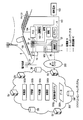
- FIG. 2 is a diagram illustrating an example of an energy management system according to the embodiment.
- the HEMS includes a client system and a cloud computing system (hereinafter abbreviated as “cloud”) 300.
- the cloud 300 can be understood as a server system that can communicate with a client system.
- the client system includes a home gateway (Home Gateway: HGW) 7 as a client device.
- the home gateway 7 is a communication device installed in the home 100 and can receive various services from the cloud 300.
- the cloud 300 includes a server computer SV and a database DB.
- the server computer SV may be single or plural.
- the database DB may be provided in one server computer SV or may be distributed and stored in a plurality of server computers SV.
- electric power (AC voltage) supplied from the power grid 6 is distributed to each home via a power pole transformer 61 and the like, and is supplied to a distribution board 20 of the home 100 via a watt-hour meter (smart meter) 19. Supplied.
- the watt-hour meter 19 has a function of measuring the power generation amount of the energy production equipment provided in the home 100, the power consumption of the home 100, the amount of power flowing from the power grid 6, or the amount of power flowing backward to the power grid 6.
- the electric power generated based on the renewable energy is allowed to flow backward to the power grid 6.
- the distribution board 20 supplies electric power to home appliances (lighting, air conditioners, heat pump water heaters (HP), etc.) 5 and a power conditioning system (PCS) 104 connected to the distribution board 20 via a distribution line 21. Supply. Moreover, the distribution board 20 is provided with the measuring device which measures the electric energy for every feeder.
- home appliances lighting, air conditioners, heat pump water heaters (HP), etc.
- PCS power conditioning system
- the electric device is a device that can be connected to the distribution line 21 in the home 100.
- Devices that consume electric power (loads), devices that generate electric power, devices that consume and generate electric power, storage batteries, and the like correspond to electric devices. That is, the home appliance 5, the PV unit 101, the storage battery 102, and the fuel cell (hereinafter referred to as FC unit) 103 all correspond to electrical devices.
- the electric device is detachably connected to the distribution line 21 via an outlet (not shown), and is connected to the distribution board 20 via the distribution line 21.
- the PV unit 101 is installed on the roof and outer wall of the home 100.
- the PV unit 101 is an energy creation device that produces electric power energy from renewable energy. Wind power generation systems are also in the category of energy creation equipment.
- the FC unit 103 is a power generation unit that produces electric power from city gas or LP gas (liquefied propane gas) that is a non-renewable energy source. Since the power generated by the FC unit 103 is prohibited from flowing backward to the power grid 6, surplus power may be generated. Surplus power can be charged to the storage battery 102.
- city gas or LP gas liquefied propane gas
- PCS 104 includes an inverter (not shown).
- the PCS 104 converts DC power supplied from the PV unit 101, the storage battery 102, or the FC unit 103 into AC power and supplies the AC power to the distribution line 21.
- the electric device can also receive power supply from the storage battery 102 and the FC unit 103 via the PCS 104.
- the PCS 104 also includes a converter (not shown). The PCS 104 converts AC power from the distribution line 21 into DC power and supplies it to the storage battery 102.
- the PCS 104 has a function as a power converter for transferring energy between the storage battery 102 and the FC unit 103 and the distribution line 21.
- the PCS 104 also has a function of controlling the storage battery 102 and the FC unit 103 to operate stably.
- FIG. 2 shows a form in which the PCS 104 is commonly connected to the PV unit 101, the storage battery 102, and the FC unit 103. Not only this form but PV101, storage battery 102, and FC unit 103 may each be provided with the function of PCS.
- a home network 25 such as a wireless local area network (LAN) is formed in the home 100.
- the home gateway 7 is detachably connected to both the home network 25 and the IP network 200 via a connector (not shown) or the like. Thereby, the home gateway 7 can communicate with the watt-hour meter 19, the distribution board 20, the PCS 104, and the home appliance 5 connected to the home network 25.
- the home network 25 may be either wireless or wired.
- the home gateway 7 includes a communication unit 7a as a processing function according to the embodiment.
- the communication unit 7 a is a network interface that transmits various data to the cloud 300 and receives various data from the cloud 300.
- the home gateway 7 is a computer having a Central Processing Unit (CPU) and a memory (not shown).
- the memory stores a program for controlling the computer.
- the program communicates with the cloud 300, requests the cloud 300 to calculate the operation schedule of the home appliance 5, the storage battery 102, and the FC unit 103, and gives instructions for reflecting the intention of the customer to control the system. Including.
- the functions of the home gateway 7 are realized by the CPU functioning based on various programs.
- the home gateway 7 transmits various data to the cloud 300 and receives various data from the cloud 300.
- the home gateway 7 is a client that can communicate with the cloud 300 and the server computer SV.
- the various data transmitted from the home gateway 7 includes request signals for requesting the cloud 300 to perform various calculations.
- the home gateway 7 is connected to the terminal 105 via a wired line or a wireless line.
- the home gateway 7 and the terminal 105 can be combined to implement a function as a local server.
- the terminal 105 may be a so-called touch panel or the like, for example, a general-purpose portable information device, a personal computer, or a tablet terminal.
- the terminal 105 displays the operating status and power consumption of the home appliance 5, the PV unit 101, the storage battery 102, and the FC unit 103 on, for example, an LCD (Liquid Crystal Display) or informs a consumer (user) by voice guidance or the like.
- the terminal 105 includes an operation panel, and accepts various operations and setting inputs by a consumer.
- the IP network 200 is the so-called Internet or a system vendor's VPN (Virtual Private Network).
- the home gateway 7 can communicate with the server computer SV via the IP network 200 and exchange data with the database DB.
- the IP network 200 may include a wireless or wired communication infrastructure for forming a bidirectional communication environment between the home gateway 7 and the cloud 300.
- the cloud 300 includes a collection unit 300a, a prediction unit 300b, a creation unit 300c, and a control unit 300d.
- the control target model 300g of the storage battery 102, the FC unit 103, and the solar water heater 106, and various types of data 300h are stored in the database DB of the cloud 300.
- the collection unit 300a, the prediction unit 300b, the creation unit 300c, and the control unit 300d are functional objects distributed and arranged in a single server computer SV or the cloud 300. Those skilled in the art will readily understand how to implement these functional objects in the system.
- the collection unit 300a, the prediction unit 300b, the creation unit 300c, and the control unit 300d are realized as programs executed by the server computer SV of the cloud 300.
- This program can be executed by a single computer or can be executed by a system including a plurality of computers.
- Various functions according to the embodiment are realized by executing the instructions described in the program.
- the collection unit 300a periodically transmits data related to home appliances 5 of the home 100, the PV unit 101, the storage battery 102, the FC unit 103, and the solar water heater 106, in other words, energy-related equipment from the home gateway 7 of each home 100. Or on an irregular basis.
- the collection unit 300 a acquires user operation history and the like on the terminal 105 from the terminal 105. Note that the collection unit 300a and the terminal 105 can directly communicate with each other via the communication line 40.
- the acquired data is stored as data 300h in the database DB.
- the data 300h includes the power demand of each home 100, the power consumption of each home appliance 5, the amount of hot water supply, the operating state, the remaining charge and charge / discharge power of the storage battery 102, the amount of power generated by the PV unit 101, and the like.
- weather data provided by the Japan Meteorological Agency can be included in the data 300h.
- the creation unit 300c creates an operation schedule of the storage battery 102 and the FC unit 103 based on the control target model 300g and the predicted energy demand and energy supply amount. That is, the creation unit 300c calculates, for example, a charge / discharge schedule of the storage battery 102 or a power generation schedule (FC power generation schedule) of the FC unit 103 based on, for example, power demand, hot water supply demand, hot water supply amount, and PV power generation amount.
- the creation unit 300 c determines the operation schedule of the storage battery 102 and the FC unit 103 in order to optimize the energy balance in the home 100. This process is called optimal scheduling.
- the energy balance is, for example, a utility bill.
- the energy balance is evaluated based on a balance between the cost of power energy consumed by the home appliance 5 and the selling price of energy generated mainly by the PV unit 101.
- the embodiment further considers using thermal energy supplied from the solar water heater 106.
- the calculated time series operation schedule of the storage battery 102 and the FC unit 103 is stored in the database DB.
- the control unit 300d controls the energy-related equipment based on the calculated operation schedule. More specifically, the control unit 300 d generates control information for controlling the storage battery 102 and the FC unit 103. That is, the controller 300d generates a charge / discharge of the storage battery 102, an operation, an operation / stop instruction for power generation of the FC unit 103, an output target value, and the like from the result of the optimal scheduling. Such control information is transmitted to the terminal 105 and the home gateway 7 via the communication line 40.
- the terminal 105 of the home 100 includes an interface unit (user interface 105a in FIG. 3) for reflecting the intention of the consumer in the control of the home appliance 5 based on the control information transmitted from the control unit 300d.
- the user interface 105 a includes a display for displaying a charge / discharge schedule of the storage battery 102 and a power generation schedule of the FC unit 103. The user can check the schedule by looking at the contents displayed on the display, and can select whether to allow or reject the execution of the displayed schedule. Thereby, a user's intention can be reflected in execution of a schedule.
- the consumer can input an instruction (command) for requesting recalculation of the schedule to the cloud 300 or giving information necessary for the calculation to the system via the user interface 105a.
- FIG. 3 is a functional block diagram illustrating a main part of the HEMS according to the first embodiment.
- various data are regularly or irregularly transmitted from the PCS 104 of the home 100, the home appliance 5, the storage battery 102, the FC unit 103, the watt hour meter 19, and the distribution board 20 via the home gateway 7. It is transmitted to the cloud 300.
- the data includes, for example, power consumption for each predetermined time of each home appliance 5, operating state, remaining charge amount and charge / discharge power amount of the storage battery 102, power demand of the home 100, hot water supply demand, PV power generation amount, solar hot water amount (solar heat The amount of hot water supplied by the water heater 106).
- the home gateway 7 transmits the relevant data to the cloud 300. Irregular means transmission at such timing.
- the operation history of the user of the terminal 105 is also transmitted to the cloud 300.
- the prediction unit 300b provided for each consumer uses the collected power data such as power demand, hot water supply demand, PV power generation amount, and weather data such as weather forecast, and the power demand per predetermined time on the target day, Predict hot water demand and PV power generation.
- Meteorological data is distributed from other servers (such as the Japan Meteorological Agency) at several times a day. You may perform prediction calculation according to the timing which received this weather data.
- the demand is predicted from the weather information and past demand data by a neural network (disclosed in Japanese Patent Application Laid-Open No. 06-267681), or the past demand data of a plurality of consumers is grouped, and an average demand fluctuation model for each group (Which is disclosed in Japanese Patent Laid-Open No. 2004-112869).
- the hot water supply demand can be predicted from, for example, calendar information (disclosed in JP 2011-83084 A).
- the PV power generation amount can be predicted based on a statistical correlation between different times in the past data or a statistical correlation between different installation positions (Japanese Patent Laid-Open No. 2011-200040).
- the solar hot water can be predicted in the same manner.
- the creation unit 300c provided for each consumer uses the energy demand, the energy supply amount, the energy unit price, and the control target model 300g calculated for each predetermined time, which are calculated by prediction calculation. Perform scheduling.
- the prediction unit 300b and the creation unit 300c can be implemented as, for example, functional objects provided exclusively for each consumer. That is, the functions of the prediction unit 300b and the creation unit 300c can be provided for each consumer. For example, such a form is possible by creating a plurality of threads in the program execution process. According to such a form, there is an advantage such as easy security.
- the prediction unit 300b and the creation unit 300c can be implemented as functional objects provided for a plurality of consumers. That is, the calculation by the prediction unit 300b and the creation unit 300c can be executed in units of a plurality of consumers. According to such a form, it is possible to obtain merits such as saving of calculation resources.
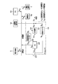
- FIG. 4 is a diagram for explaining the control target model 300g according to the first embodiment.
- Control target model 300g includes power grid 6, FC unit 103, solar water heater 106, storage battery 102, PV unit 101, and load (home appliance) 205 as elements.
- the FC unit 103 includes an FC main body 220, an auxiliary boiler 221, a reverse power flow prevention heater 222, and a hot water tank 223 as elements.
- the variables shown in FIG. 4 are shown below.
- the control target model 300g shows an input / output relationship between the elements and a relational expression between the input variables or the output variables between the elements.
- the control target model 300g can be expressed by the following equations (1) to (11).
- the gas supply amount F (t) is shown as the sum of the supply amount F FC (t) to FC and the supply amount F B (t) to the auxiliary boiler.
- the FC main body 220 generates power by P FC (t) with respect to the gas supply amount of F FC (t) and exhausts heat by Q FC (t).
- the input / output characteristics of the FC main body 220 can be approximated as shown in equations (2) and (3). That is, the input / output characteristics of the FC main body 220 are indicated by the relationship between the gas supply amount, the power generation amount, and the exhaust heat amount in the FC main body 220.
- the reverse power flow prevention heater 222 converts the surplus power P H (t) into heat of the heat quantity Q H (t) and consumes it. That is, the reverse power flow prevention heater 222 prevents the surplus power P H (t) from flowing back to the power grid 6 by discarding the heat quantity Q H (t).
- the auxiliary boiler 221 supplies hot water supply Q B (t) that cannot be covered by the hot water supply Q ST (t) from the hot water storage tank 223 in the hot water supply demand.
- the hot water storage amount H (t) of the hot water storage tank 223 is the exhaust heat Q FC (t) of the FC main body 220, the heat generation amount Q H (t) of the reverse flow prevention heater 222, and the hot water supply Q ST. Increase or decrease by (t).
- the left side of equation (4) represents the amount of heat entering the hot water tank 223 on a hot water basis.
- the hot water storage efficiency (residual rate) r is a coefficient indicating the proportion of heat remaining after a decrease due to heat dissipation between times t-1 and t.
- the second term on the left side of Equation (4) is the recovered amount of FC exhaust heat.
- the third term is the amount of heat generated by the reverse power flow prevention heater. Both of the second term and the third term are hot water equivalent values. In the case where the hot water supply pipe from the solar water heater 106 is connected to the hot water storage tank 223, Q S (t) is added to the left side of the equation (4), and Q S ( t) is deleted.
- Equation (4) represents the amount of heat emitted from the hot water tank 223 and the remaining amount of heat on a hot water basis.
- the first term on the right side represents the current hot water storage amount, and the second term represents the current hot water supply amount (strictly, the hot water supply amount between times t-1 and t).
- Equation (5) shows the capacity restriction of the hot water tank 223.
- the storage battery 102 can be modeled as a model in which the remaining charge S (t) increases or decreases depending on the charge / discharge power P SB (t).
- Formula (6) shows the power supply-demand balance.
- P D (t) indicates the power demand of the home 100
- P C (t) indicates purchased power or sold power
- P PV (t) indicates the power generation amount of the PV unit 101.
- Expressions (7) and (8) indicate the constraint condition that the reverse power flow from the FC main body 220 and the storage battery 102 is prohibited.
- Equation (9) shows the constraint condition of the capacity of the storage battery 102.
- Expression (10) shows a constraint condition that the change of the power generation amount with respect to time of the FC unit 103 (FC main body 220) is limited within a predetermined range.
- the expression (10) indicates that the amount of change in the power generation amount of the FC main body 220 during a period from a certain time t-1 to the next time t is the lower limit of the decrease rate of the FC power generation amount ⁇ P FC_DOWN and the FC power generation amount This is a constraint condition that the upper limit of the increase speed is limited to P FC_UP .
- the hot water supply demand Q D (t) includes the hot water supply amount Q ST (t) from the hot water tank 223, the hot water supply amount Q B (t) from the auxiliary boiler, and the solar water heater as shown in the equation (11). Covered with hot water supply Q S (t) from 106.
- the creation unit 300c determines the FC unit 103 based on the power demand, hot water supply demand, PV power generation amount, the amount of hot water from the solar water heater 106, the unit price of electricity / gas, and the power purchase price.
- a schedule for power generation P FC (t) and a schedule for charge / discharge P SB (t) of the storage battery 102 are created.
- Each schedule is created by, for example, an optimization algorithm in order to minimize the utility cost (energy cost) under the constraint that the surplus power discarded when the storage battery 102 is fully charged is minimized. For example, a genetic algorithm can be used as the optimization algorithm.
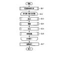
- FIG. 5 is a flowchart illustrating an example of a processing procedure according to the first embodiment.
- the optimization calculation requires processing such as power demand prediction, hot water supply demand prediction, and PV power generation amount prediction.
- the optimization calculation is executed at the timing of several times a day when the prediction calculation is executed.
- the prediction unit 300b acquires each data related to the power demand, the hot water supply demand, the PV power generation amount, and the solar hot water amount every predetermined time from the database DB (step S1-1). In this step, not only current data but also past data such as data on the same day of the previous year may be acquired. Next, the prediction unit 300b predicts a power demand, a hot water supply demand, a PV power generation amount, and a solar hot water amount every predetermined time for calculation of an operation schedule (step S1-2).
- the creation unit 300c calculates a schedule for each predetermined time of the power generation amount of the FC unit 103 and the charge / discharge amount of the storage battery 102 so as to minimize the utility bill (step S1-3).
- the calculated schedule is stored in the database DB.
- the system transmits a message signal indicating the charge / discharge amount schedule of the storage battery 102 or the schedule of the power generation amount of the FC unit 103 to the terminal 105 via the IP network 200.
- the terminal 105 decodes the message signal and displays various schedules on the interface (step S1-4). Routines related to message message transmission and display are executed periodically or in response to a request from the user.
- the cloud 300 waits for the arrival of a permission message signal indicating that the execution of the operation schedule is permitted by the user (step S1-5). If permitted, the control unit 300d transmits control information for controlling the home appliance 5 of the home 100 according to the schedule (created by the creation unit 300c) to the home gateway 7 of the home 100 via the IP network 200 (step S1-6).
- the control information includes, for example, charge / discharge of the storage battery 102, an operation / stop instruction for power generation of the FC unit 103, an output target value, and the like. The above procedure is repeated for each optimum scheduling time interval.
- the generated control information is transmitted to the home gateway 7 of the home 100.
- the user instructs the system via the user interface 105a whether control is possible based on the transmitted control information.
- the user interface 105a displays the current state of the solar water heater 106 and predicted data of the state. In addition, the temperature, volume, amount of heat of the hot water storage, a value converted into fuel and electric power necessary for generation, or the amount of use thereof may be displayed.
- FIG. 6 is a conceptual diagram showing an example of gene design of the genetic algorithm according to the first embodiment.
- the power generation amount P FC (t) of the FC unit 103 and the charge / discharge power P SB (t) of the storage battery 102 are incorporated into the gene.
- the operation schedule of the storage battery 102 and the FC unit 103 for one day is an individual, and the generation includes a plurality of individuals.
- Equation (12) shows the fitness Fit to be maximized. By optimizing this Fit as an objective function, the driving schedule can be calculated.
- Formula (13) shows the utility cost balance C.
- the fitness Fit shown in the equation (12) is a monotonically increasing function f (C) having a utility cost C per day as a variable and a cost g (P FC , P SB ) required for discontinuity in equipment operation> The reciprocal of the sum with zero. If the PV power generation amount greatly exceeds the power demand of the home 100, the utility bill C may become negative. Therefore, in order to correspond to the decrease in the utility bill C and the increase in fitness Fit, A form is adopted. In the first embodiment, a function satisfying f (C)> 0 is used.
- FIG. 7 is a flowchart illustrating an example of the flow of the optimization calculation according to the first embodiment.
- a genetic algorithm is taken as an example of an optimization algorithm. The processing procedure based on the genetic algorithm will be described below.
- Step S2-1 Generation of initial population
- the calculation unit 300c generates n initial individuals.
- the individual gene includes, for example, operation / stop of the FC unit 103 at time t, power generation amount of the FC unit 103, charge / discharge power of the storage battery 102, and the like. For example, one day (24 hours) can be provided as a gene string.
- Each individual is a set of gene sequences of the FC unit 103 and the storage battery 102. Solids that do not satisfy the constraint condition are bit-inverted to modify the gene to satisfy the constraint condition.
- Step S2-2 The loop of step S2-2 is a process of repeating the processes of steps S2-3 to S2-6. When this loop reaches the specified number of times, the algorithm operation is finished. In addition, the fitness of each individual and the average fitness of the generation are calculated. The average fitness in that generation is compared with the average fitness of the previous two generations. If the result of the comparison is less than or equal to the arbitrarily set value ⁇ , the algorithm operation is terminated.
- the calculation unit 300c excludes individuals that do not satisfy the constraint conditions. Therefore, individuals who do not satisfy the constraints are deceived. If there are more than a predetermined number of individuals, individuals with poor fitness (small fitness) are excluded, and the number of individuals is kept below the predetermined number.
- Step S2-4 Proliferation In this step, when the number of individuals is smaller than the number of individuals defined in advance, the calculation unit 300c proliferates individuals with the best fitness.
- Crossover Calculation unit 300c performs pairing at random. Pairing is performed as much as the ratio (crossover rate) to the total number of individuals, and gene loci are randomly selected for each pair and crossed at one point.
- Step S2-6) Mutation In this step, the calculation unit 300c randomly selects individuals by a ratio (mutation rate) with respect to the total number of individuals, and genes at arbitrary (determined randomly) loci of each individual. Invert the bit.
- Step S2-3) to (Step S2-6) is repeated while incrementing the number of generations until the condition of the number of generations ⁇ the maximum number of generations is satisfied (loop of Step S2-2). If this condition is satisfied, the calculation unit 300c outputs the result (step S2-7) and ends the calculation procedure.
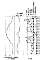
- FIG. 8 is a diagram for explaining the effects obtained by the first embodiment.
- FIG. 8 shows an example of an operation schedule for one day of the storage battery 102 and the FC unit 103 calculated based on the prediction results of the daily power demand and hot water supply demand of the home 100.
- the unit price of electricity was assumed to be 28 yen / kWh from 7:00 to 23:00 and 9 yen / kWh from 23:00 to 7:00 the next day.
- the calculation result using only the electric power demand, the hot water supply demand, the electricity, and the gas unit price is shown without assuming the improvement of the utility bill due to the power sale.
- the operation schedule of the storage battery 102 is charged in a time zone where the unit price of electricity is low (from 0:00 to 6:00), and a time zone where the unit price of electricity is high (from 7:00 to 10:00, from 13:00 to 22:00). ) To discharge. Thereby, since the purchased electric power in the time zone with a high electricity bill unit price decreases, an electricity bill can be reduced.
- the FC unit 103 is operated at the maximum output, and the surplus power generation amount is charged in the storage battery 102 during a time period (12:00 to 14:00) when the power generation amount exceeds the power demand. Therefore, it is possible to prevent the generated power from being consumed (discarded) wastefully by the reverse flow prevention heater 222, and it is possible to reduce gas costs. It is understood that the reverse power flow prevention heater 222 has changed without operating for 24 hours.
- FIG. 8 shows a graph showing the transition of the total hot water storage amount by time on a calorie basis.
- This graph shows the sum of the amount of hot water of, for example, 45 ° C. or more in the hot water storage tank 223 and the amount of hot water of the same temperature pooled in the solar water heater 106.
- This graph basically shows daily fluctuations similar to the PV power generation amount, but also changes according to changes in the operating state of the FC unit 103 and hot water supply demand.
- the PV power generation amount, power demand, hot water supply demand, and solar hot water amount in the home 100 are predicted. Then, based on each predicted value, energy management is performed so as to minimize the energy cost (utilization cost) by executing an optimization calculation that minimizes the evaluation function under preset constraint conditions. That is, the operation schedule of the FC unit 103 and the charge / discharge schedule of the storage battery 102 are optimized based on a control model in which the power generation amount of the FC unit 103 is variable and the amount of solar hot water is incorporated. As a result, it is possible to create a schedule that can reduce the utility cost without wastefully operating the reverse power flow prevention heater 222.
- the function indicating the fitness Fit to be maximized includes the gas charge required for the operation of the FC unit 103.
- a schedule for operating the reverse flow prevention heater 222 in vain under the condition that a possible solution exists is deceived in the process of optimization calculation.
- the amount of change in the power generation amount of the FC unit 103 from a certain time t ⁇ 1 to the next time t is expressed as ⁇ P FC_DOWN (the decrease rate of the power generation amount of the FC unit 103).
- a constraint condition is set such that it falls within the range of (lower limit value) to P FC_UP (upper limit value of the increase rate of power generation amount of the FC unit 103).
- step S1-2 by combining the prediction procedure of step S1-2 and the optimal scheduling (FIG. 5) of step S1-3, power demand prediction, hot water supply demand prediction, PV power generation prediction, According to the solar hot water amount prediction, a supply and demand plan such as a power generation schedule of the FC unit 103 and a charge / discharge schedule of the storage battery 102 can be created in consideration of the overall balance.
- the first embodiment it is possible to effectively use surplus power that cannot reversely flow into the commercial power system without wasting it. Accordingly, it is possible to provide an energy management system, an energy management method, a program, and a server that can prevent excess power from being wasted.
- FIG. 9 is a functional block diagram illustrating a main part of the HEMS according to the second embodiment.
- the same reference numerals are given to the portions common to FIG. 3, and only different portions will be described here.
- 2nd Embodiment it replaces with FC unit 103 and assumes the case where the heat pump type hot water heater (HP) 110 which uses underground thermal energy is used together.
- the heat pump hot water heater 110 is controlled by the control unit 300d based on the optimized operation schedule.
- FIG. 10 is a diagram for explaining a control target model 300g according to the second embodiment.
- the FC main body 220 is replaced with a heat pump type water heater 110. Since the heat pump type hot water heater 110 is superior in control responsiveness compared to the FC unit 103, the reverse power flow prevention heater 222 can be eliminated.
- the following equations (15) to (22) show the relationship between the variables in FIG.
- the heat pump type water heater 110 is incorporated in the optimization calculation. That is, the creation unit 300c performs an optimization calculation to minimize the evaluation function based on the power demand prediction and hot water supply demand prediction of the home 100 and the underground heat energy, and creates an operation schedule. According to the second embodiment, since the fuel of the FC unit 103 is not necessary, further cost merit can be obtained.
- the present invention is not limited to the above embodiment.
- the use of the genetic algorithm has been described, but the genetic algorithm is not the only solution for calculating the driving schedule. It is possible to calculate an optimal driving schedule using various other algorithms.
- heat may be recovered from the remaining hot water in the bathtub using a heat exchanger, and hot water from a solar water heater or hot water from a heat pump water heater may be heated with the recovered heat. That is, the home 100 may be provided with a heat exchanger that exchanges heat energy between the hot water supplied from the water heater and the hot water in the bathtub.
- the creation unit 300c creates an operation schedule based on the predicted energy demand, energy supply amount, and thermal energy.
- information regarding the heat balance from the outside such as solar thermal energy and underground thermal energy, may be displayed on the user interface 105a. In this way, it is possible to make the user who tends to focus only on power energy aware of thermal energy.
Landscapes
- Engineering & Computer Science (AREA)
- Physics & Mathematics (AREA)
- General Engineering & Computer Science (AREA)
- Mechanical Engineering (AREA)
- Combustion & Propulsion (AREA)
- Chemical & Material Sciences (AREA)
- Thermal Sciences (AREA)
- Power Engineering (AREA)
- Business, Economics & Management (AREA)
- Health & Medical Sciences (AREA)
- Economics (AREA)
- Water Supply & Treatment (AREA)
- Marketing (AREA)
- Strategic Management (AREA)
- General Business, Economics & Management (AREA)
- General Physics & Mathematics (AREA)
- Theoretical Computer Science (AREA)
- Primary Health Care (AREA)
- Tourism & Hospitality (AREA)
- Human Resources & Organizations (AREA)
- General Health & Medical Sciences (AREA)
- Public Health (AREA)
- Computer Hardware Design (AREA)
- Supply And Distribution Of Alternating Current (AREA)
- Heat-Pump Type And Storage Water Heaters (AREA)
- Management, Administration, Business Operations System, And Electronic Commerce (AREA)
- Charge And Discharge Circuits For Batteries Or The Like (AREA)
Abstract
According to an embodiment of the invention, an energy management system manages the energy of a user provided with a water heater, the water heater using a renewable energy as a heat source. The energy management system is equipped with an acquisition unit, a forecasting unit, a preparation unit, and a control unit. The acquisition unit acquires from the user data relating to energy-relevant devices including the water heater, a power-generating apparatus, an electric storage apparatus, and an energy-consuming device. The forecasting unit forecasts the demand and supply amount of energy of the user on the basis of the data. The preparation unit prepares an operation schedule on the basis of the amount of energy demanded and supplied to minimize the energy cost of the user under conditions where the surplus power wasted due to the full charge of the electric storage apparatus is minimized. The control unit controls the energy-relevant devices on the basis of the operation schedule.
Description
本発明の実施形態は、需要家(カスタマー)側におけるエネルギー収支を管理するエネルギー管理システム、エネルギー管理方法、プログラムおよびサーバに関する。
Embodiments of the present invention relate to an energy management system, an energy management method, a program, and a server that manage an energy balance on a customer (customer) side.
近年の環境保全意識の高まりと電力不足への不安を背景に、ゼロエネルギー住宅(Zero Energy Home:ZEH)、あるいはネット・ゼロエネルギー住宅に注目が集まっている。ネット・ゼロエネルギー住宅は、年間の一次エネルギー消費量がネット(正味)で概ねゼロとなる住宅を意味する。この種の住宅の実現には、太陽光発電(Photovoltaic Power Generation:PV)システム、蓄電池、あるいは燃料電池(Fuel Cell:FC)などの分散型電源と、家庭エネルギー管理システム(Home Energy Management System:HEMS)とが不可欠である。
】 In recent years, attention has been focused on zero energy homes (ZEH) or net zero energy homes against the backdrop of rising awareness of environmental conservation and concerns about power shortages. Net zero energy housing means a home where annual primary energy consumption is almost zero on the net. Realization of this type of housing involves a distributed power source such as a photovoltaic (Powervoltaic Power Generation: PV) system, a storage battery, or a Fuel Cell (FC), and a home energy management system (HEMS). ) And are indispensable.
FCは、昼夜、天候を問わず安定して発電でき、排熱を利用して熱エネルギーを供給できるので、分散型電源のなかでも特に有望視されている。しかしながらFCから商用電力系統(grid)への逆潮流は、電力会社との契約上、許されていない。そこで、FCにより発電された電力の逆潮流を防止するための技術が幾つか提案されている。
FC is particularly promising among distributed power sources because it can generate power stably day and night regardless of the weather and can supply heat energy using exhaust heat. However, reverse power flow from FC to the commercial power grid is not allowed under contract with the power company. Therefore, several techniques for preventing reverse power flow of power generated by FC have been proposed.
逆潮流を防止するための対策として、FCによる余剰電力をダミー負荷やヒータで消費するという技術がある。これではエネルギーが無駄に消費される。余剰電力を蓄電池に充電するという技術もあるが、充電の必要が生じたときに既に蓄電池が満充電であり、充電できないことも考えられる。
Measures to prevent reverse power flow include a technique of consuming surplus power from FC with a dummy load or heater. This wastes energy. There is also a technique of charging surplus power to the storage battery, but it is also conceivable that the storage battery is already fully charged when charging becomes necessary and cannot be charged.
ヒータと蓄電池とを併用しても、FCの出力を変化させるには長い時間を要するので、電力需要(デマンド)の少ない時間が長期に渡ると余剰電力の発生量が蓄電池容量を上回ってしまう。このようなケースではFCの運転を停止するか、ヒータで余剰電力を消費せざるを得ない。リレーにより系統から解列することで逆潮流を防止するにしても、生じた余剰電力は無駄に消費されているのが現状である。
Even if a heater and a storage battery are used in combination, it takes a long time to change the output of the FC. Therefore, if the amount of power demand (demand) is long, the amount of surplus power generated will exceed the storage battery capacity. In such a case, it is necessary to stop the operation of the FC or to consume surplus power with the heater. Even if the reverse power flow is prevented by disconnecting from the system by a relay, the surplus power generated is currently wasted.
その一方で、太陽熱や地中熱などの熱源を有効に利用すれば、余剰電力をグリッドに売電してコストメリットを得られる可能性がある。このように、直接、熱エネルギーとして利用可能な再生可能エネルギーをも考慮して余剰電力の無駄な消費を抑えようとする技術は知られていない。
On the other hand, if a heat source such as solar heat or underground heat is used effectively, there is a possibility that surplus power can be sold to the grid and cost merit can be obtained. As described above, there is no known technique for suppressing wasteful consumption of surplus power in consideration of renewable energy that can be directly used as thermal energy.
目的は、余剰電力が無駄に消費されることを防止可能なエネルギー管理システム、エネルギー管理方法、プログラムおよびサーバを提供することにある。
An object is to provide an energy management system, an energy management method, a program, and a server capable of preventing surplus power from being consumed unnecessarily.
実施形態によれば、エネルギー管理システムは、再生可能エネルギーを熱源とする給湯器を備える需要家のエネルギーを管理する。このエネルギー管理システムは、取得部と、予測部と、作成部と、制御部とを具備する。取得部は、給湯器、発電装置、蓄電装置およびエネルギー消費機器を含むエネルギー関連機器に係わるデータを需要家から取得する。予測部は、取得されたデータに基づいて需要家におけるエネルギーデマンドおよびエネルギー供給量を予測する。作成部は、蓄電装置の満充電に伴い破棄される余剰電力を最小化する条件下で、需要家におけるエネルギーコストを最小化すべく、予測されたエネルギーデマンドおよびエネルギー供給量に基づいてエネルギー関連機器の運転スケジュールを作成する。制御部は、作成された運転スケジュールに基づいてエネルギー関連機器を制御する。
According to the embodiment, the energy management system manages the energy of a customer including a water heater that uses renewable energy as a heat source. The energy management system includes an acquisition unit, a prediction unit, a creation unit, and a control unit. The acquisition unit acquires data related to energy-related devices including a water heater, a power generation device, a power storage device, and energy consuming devices from a consumer. The prediction unit predicts the energy demand and energy supply amount in the consumer based on the acquired data. The creation unit, based on the predicted energy demand and energy supply amount, minimizes the energy cost at the consumer under the condition of minimizing the surplus power discarded when the power storage device is fully charged. Create a driving schedule. The control unit controls the energy-related device based on the created operation schedule.
図1は、実施形態に係わるシステムの一例を示す図である。図1は、いわゆるスマートグリッドとして知られるシステムの一例を示す。既存の電力網(grid)では原子力、火力、水力などの既存発電所と、一般家庭や、ビル、工場といった多種多様な需要家とが電力網によって接続される。次世代の電力系統(Power grid)ではこれらに加えて太陽光発電(Photovoltaic Power Generation:PV)システムや風力発電装置などの分散型電源や蓄電装置、新交通システムや充電スタンドなどが電力系統に接続される。これら多種多様な要素は通信グリッドを介して通信することが可能である。
FIG. 1 is a diagram illustrating an example of a system according to the embodiment. FIG. 1 shows an example of a system known as a so-called smart grid. In the existing grid (grid), existing power plants such as nuclear power, thermal power, and hydropower are connected to a wide variety of consumers such as ordinary households, buildings, and factories through the power grid. In addition to these in the next generation power grid (Power grid), distributed power sources such as photovoltaic (Powervoltaic Power Generation: PV) systems and wind power generators, power storage devices, new transportation systems and charging stations are connected to the power grid. Is done. These various elements can communicate via a communication grid.
エネルギーを管理するシステムは、エネルギーマネジメントシステム(Energy Management System:EMS)と総称される。EMSはその規模などに応じて幾つかに分類される。例えば一般家庭向けのHEMSのほか、ビルディング向けのBEMS(Building Energy Management System)などがある。このほか、集合住宅向けのMEMS(Mansion Energy Management System)、コミュニティ向けのCEMS(Community Energy Management System)、工場向けのFEMS(Factory Energy Management System)などがある。これらのシステムが連携することできめ細かなエネルギー最適化制御が実現される。
∙ Energy management systems are collectively referred to as Energy Management System (EMS). EMS is classified into several types according to its size. For example, in addition to HEMS for general households, there are BEMS (Building Energy Management System) for buildings. In addition, there are MEMS (Mansion Energy Management System) for collective housing, CEMS (Community Energy Management System) for communities, and FEMS (Factory Energy Management System) for factories. Fine energy optimization control can be realized by linking these systems.
これらのシステムによれば既存の発電所、分散型電源、太陽光や風力などの再生可能エネルギー源、および需要家の相互間で高度な協調運用が可能になる。これにより再生可能エネルギーを主体とするエネルギー供給システムや、需要家と事業者との双方向連携による需要家参加型のエネルギー需給といった、新規かつスマートな形態の電力供給サービスが生み出される。
These systems enable highly coordinated operation among existing power plants, distributed power sources, renewable energy sources such as solar and wind power, and consumers. As a result, a new and smart power supply service such as an energy supply system mainly composed of renewable energy and a consumer-participation type energy supply and demand through two-way cooperation between a customer and an operator is created.
図2は、実施形態に係るエネルギー管理システムの一例を示す図である。HEMSは、クライアントシステムと、クラウドコンピューティングシステム(以下、クラウドと略称する)300とを備える。クラウド300は、クライアントシステムと通信可能なサーバシステムとして理解されることが可能である。
クライアントシステムは、クライアント装置としてのホームゲートウェイ(Home Gateway:HGW)7を備える。ホームゲートウェイ7はホーム100に設置される通信装置であり、クラウド300から各種のサービスの提供を受けることができる。 FIG. 2 is a diagram illustrating an example of an energy management system according to the embodiment. The HEMS includes a client system and a cloud computing system (hereinafter abbreviated as “cloud”) 300. Thecloud 300 can be understood as a server system that can communicate with a client system.
The client system includes a home gateway (Home Gateway: HGW) 7 as a client device. Thehome gateway 7 is a communication device installed in the home 100 and can receive various services from the cloud 300.
クライアントシステムは、クライアント装置としてのホームゲートウェイ(Home Gateway:HGW)7を備える。ホームゲートウェイ7はホーム100に設置される通信装置であり、クラウド300から各種のサービスの提供を受けることができる。 FIG. 2 is a diagram illustrating an example of an energy management system according to the embodiment. The HEMS includes a client system and a cloud computing system (hereinafter abbreviated as “cloud”) 300. The
The client system includes a home gateway (Home Gateway: HGW) 7 as a client device. The
クラウド300は、サーバコンピュータSVとデータベースDBとを備える。サーバコンピュータSVは単体でも複数でも良い。データベースDBは一つのサーバコンピュータSVに備えられていても、複数のサーバコンピュータSVに分散して記憶されてもよい。
The cloud 300 includes a server computer SV and a database DB. The server computer SV may be single or plural. The database DB may be provided in one server computer SV or may be distributed and stored in a plurality of server computers SV.
図2において、電力グリッド6から供給される電力(交流電圧)は、電柱の変圧器61などを経て各家庭に分配され、電力量計(スマートメータ)19を経てホーム100の分電盤20に供給される。電力量計19は、ホーム100に備わるエネルギー生産機器の発電量、ホーム100の電力消費量、電力グリッド6から流れ込む電力量、あるいは電力グリッド6に逆潮流する電力量などを計測する機能を備える。周知のように、再生可能エネルギーに基づいて発電された電力は、電力グリッド6に逆潮流することを許される。
In FIG. 2, electric power (AC voltage) supplied from the power grid 6 is distributed to each home via a power pole transformer 61 and the like, and is supplied to a distribution board 20 of the home 100 via a watt-hour meter (smart meter) 19. Supplied. The watt-hour meter 19 has a function of measuring the power generation amount of the energy production equipment provided in the home 100, the power consumption of the home 100, the amount of power flowing from the power grid 6, or the amount of power flowing backward to the power grid 6. As is well known, the electric power generated based on the renewable energy is allowed to flow backward to the power grid 6.
分電盤20は配電線21を介して、この分電盤20に接続される家電機器(照明、エアコン、あるいはヒートポンプ式給湯器(HP)など)5やパワーコンディショニングシステム(PCS)104に電力を供給する。また分電盤20は、フィーダごとの電力量を計測する計測装置を備える。
The distribution board 20 supplies electric power to home appliances (lighting, air conditioners, heat pump water heaters (HP), etc.) 5 and a power conditioning system (PCS) 104 connected to the distribution board 20 via a distribution line 21. Supply. Moreover, the distribution board 20 is provided with the measuring device which measures the electric energy for every feeder.
ホーム100は、電気機器を備える。電気機器はホーム100内の配電線21に接続可能な機器である。電力を消費する機器(負荷)、電力を生成する機器、電力を消費し生成する機器、および蓄電池などが電気機器に該当する。つまり家電機器5、PVユニット101、蓄電池102および燃料電池(以下、FCユニットと表記する)103などが、いずれも電気機器に相当する。電気機器はコンセント(図示せず)を介して配電線21に着脱可能に接続され、配電線21を介して分電盤20に接続される。
Home 100 is equipped with electrical equipment. The electric device is a device that can be connected to the distribution line 21 in the home 100. Devices that consume electric power (loads), devices that generate electric power, devices that consume and generate electric power, storage batteries, and the like correspond to electric devices. That is, the home appliance 5, the PV unit 101, the storage battery 102, and the fuel cell (hereinafter referred to as FC unit) 103 all correspond to electrical devices. The electric device is detachably connected to the distribution line 21 via an outlet (not shown), and is connected to the distribution board 20 via the distribution line 21.
ホーム100の屋根や外壁にはPVユニット101が設置される。PVユニット101は、再生可能エネルギーから電力エネルギーを生産する創エネルギー機器である。風力発電システムなども創エネルギー機器の範疇に入る。
The PV unit 101 is installed on the roof and outer wall of the home 100. The PV unit 101 is an energy creation device that produces electric power energy from renewable energy. Wind power generation systems are also in the category of energy creation equipment.
FCユニット103は、非再生可能エネルギー源である都市ガスやLPガス(液化プロパンガス)から電力を生産する発電ユニットである。FCユニット103により生成された電力は電力グリッド6に逆潮流することを禁止されているので、余剰電力を生じることがある。余剰電力は蓄電池102に充電されることが可能である。
The FC unit 103 is a power generation unit that produces electric power from city gas or LP gas (liquefied propane gas) that is a non-renewable energy source. Since the power generated by the FC unit 103 is prohibited from flowing backward to the power grid 6, surplus power may be generated. Surplus power can be charged to the storage battery 102.
PCS104はインバータ(図示せず)を備える。PCS104は、PVユニット101、蓄電池102あるいはFCユニット103から供給される直流電力を交流電力に変換して、配電線21に供給する。これにより、電気機器はPCS104を介して、蓄電池102やFCユニット103からも電力の供給を受けることができる。また、PCS104はコンバータ(図示せず)を備える。PCS104は、配電線21からの交流電力を直流電力に変換して蓄電池102に供給する。
PCS 104 includes an inverter (not shown). The PCS 104 converts DC power supplied from the PV unit 101, the storage battery 102, or the FC unit 103 into AC power and supplies the AC power to the distribution line 21. As a result, the electric device can also receive power supply from the storage battery 102 and the FC unit 103 via the PCS 104. The PCS 104 also includes a converter (not shown). The PCS 104 converts AC power from the distribution line 21 into DC power and supplies it to the storage battery 102.
要するにPCS104は、蓄電池102およびFCユニット103と配電線21との間でエネルギーを授受するための、電力変換器としての機能を備える。PCS104は蓄電池102やFCユニット103を安定して稼働させるために制御する機能も備える。なお図2において、PCS104がPVユニット101、蓄電池102およびFCユニット103に共通に接続される形態が示される。この形態に限らず、PV101、蓄電池102およびFCユニット103がそれぞれ個々にPCSの機能を備えてもよい。
In short, the PCS 104 has a function as a power converter for transferring energy between the storage battery 102 and the FC unit 103 and the distribution line 21. The PCS 104 also has a function of controlling the storage battery 102 and the FC unit 103 to operate stably. FIG. 2 shows a form in which the PCS 104 is commonly connected to the PV unit 101, the storage battery 102, and the FC unit 103. Not only this form but PV101, storage battery 102, and FC unit 103 may each be provided with the function of PCS.
さらに、ホーム100の屋根には太陽熱温水器106が設置される。太陽熱温水器106は、再生可能エネルギーである太陽熱を熱源として温水を生成する創エネルギー機器、である。生成された温水はホーム100の給湯配管(図示せず)に供給される。ホーム100のエネルギー収支を最適化するために、太陽熱温水器106により得られた熱エネルギーを利用することが可能である。
Furthermore, a solar water heater 106 is installed on the roof of the home 100. The solar water heater 106 is an energy creation device that generates hot water using solar heat, which is renewable energy, as a heat source. The generated hot water is supplied to a hot water supply pipe (not shown) of the home 100. In order to optimize the energy balance of the home 100, the thermal energy obtained by the solar water heater 106 can be used.
ホーム100には無線LAN(Local Area Network)などのホームネットワーク25が形成される。ホームゲートウェイ7はホームネットワーク25とIPネットワーク200との双方に、コネクタ(図示せず)などを介して着脱可能に接続される。これによりホームゲートウェイ7は、ホームネットワーク25に接続される電力量計19、分電盤20、PCS104、および家電機器5と相互に通信可能である。なおホームネットワーク25は無線、あるいは有線のいずれでも良い。
A home network 25 such as a wireless local area network (LAN) is formed in the home 100. The home gateway 7 is detachably connected to both the home network 25 and the IP network 200 via a connector (not shown) or the like. Thereby, the home gateway 7 can communicate with the watt-hour meter 19, the distribution board 20, the PCS 104, and the home appliance 5 connected to the home network 25. The home network 25 may be either wireless or wired.
ホームゲートウェイ7は、実施形態に係る処理機能として通信部7aを備える。通信部7aは、クラウド300に各種のデータを送信し、またクラウド300から各種のデータを受信する、ネットワークインタフェースである。
The home gateway 7 includes a communication unit 7a as a processing function according to the embodiment. The communication unit 7 a is a network interface that transmits various data to the cloud 300 and receives various data from the cloud 300.
ホームゲートウェイ7はCentral Processing Unit(CPU)とメモリ(図示せず)を備えるコンピュータである。メモリは、このコンピュータを制御するプログラムを記憶する。プログラムは、クラウド300と通信したり、家電機器5や蓄電池102、FCユニット103の運転スケジュールの計算をクラウド300に要求したり、システムの制御に需要家の意思を反映させたりするための命令を含む。CPUが各種のプログラムに基づいて機能することで、ホームゲートウェイ7に係る諸機能が実現される。
The home gateway 7 is a computer having a Central Processing Unit (CPU) and a memory (not shown). The memory stores a program for controlling the computer. The program communicates with the cloud 300, requests the cloud 300 to calculate the operation schedule of the home appliance 5, the storage battery 102, and the FC unit 103, and gives instructions for reflecting the intention of the customer to control the system. Including. The functions of the home gateway 7 are realized by the CPU functioning based on various programs.
すなわちホームゲートウェイ7は、クラウド300に各種のデータを送信し、またクラウド300から各種のデータを受信する。ホームゲートウェイ7は、クラウド300、サーバコンピュータSVと通信可能なクライアントである。ホームゲートウェイ7から送信される各種データには、クラウド300に各種の演算を要求するための要求信号が含まれる。
That is, the home gateway 7 transmits various data to the cloud 300 and receives various data from the cloud 300. The home gateway 7 is a client that can communicate with the cloud 300 and the server computer SV. The various data transmitted from the home gateway 7 includes request signals for requesting the cloud 300 to perform various calculations.
ホームゲートウェイ7は有線回線または無線回線を介して端末105に接続される。ホームゲートウェイ7と端末105とを合わせてローカルサーバとしての機能を実現することも可能である。端末105はいわゆるタッチパネルなどのほか、例えば汎用的な携帯情報機器やパーソナルコンピュータ、あるいはタブレット端末などでもよい。
The home gateway 7 is connected to the terminal 105 via a wired line or a wireless line. The home gateway 7 and the terminal 105 can be combined to implement a function as a local server. The terminal 105 may be a so-called touch panel or the like, for example, a general-purpose portable information device, a personal computer, or a tablet terminal.
端末105は家電機器5、PVユニット101、蓄電池102、FCユニット103の稼働状況や電力消費量を例えばLCD(Liquid Crystal Display)に表示したり、音声ガイダンスなどで需要家(ユーザ)に報知する。また端末105は操作パネルを備え、需要家による各種の操作や設定入力を受け付ける。
The terminal 105 displays the operating status and power consumption of the home appliance 5, the PV unit 101, the storage battery 102, and the FC unit 103 on, for example, an LCD (Liquid Crystal Display) or informs a consumer (user) by voice guidance or the like. The terminal 105 includes an operation panel, and accepts various operations and setting inputs by a consumer.
IPネットワーク200は、いわゆるインターネット、あるいはシステムベンダのVPN(Virtual Private Network)などである。ホームゲートウェイ7は、IPネットワーク200を経由してサーバコンピュータSVと通信したり、データベースDBとデータを授受したりできる。なおIPネットワーク200は、ホームゲートウェイ7とクラウド300との間に双方向の通信環境を形成するための、無線または有線の通信インフラストラクチャを含んで良い。
The IP network 200 is the so-called Internet or a system vendor's VPN (Virtual Private Network). The home gateway 7 can communicate with the server computer SV via the IP network 200 and exchange data with the database DB. The IP network 200 may include a wireless or wired communication infrastructure for forming a bidirectional communication environment between the home gateway 7 and the cloud 300.
クラウド300は、収集部300a、予測部300b、作成部300c、および制御部300dを備える。また、蓄電池102、FCユニット103および太陽熱温水器106の制御対象モデル300g、および各種のデータ300hがクラウド300のデータベースDBに記憶される。収集部300a、予測部300b、作成部300c、および制御部300dは、単体のサーバコンピュータSV、あるいは、クラウド300に分散配置される機能オブジェクトである。これらの機能オブジェクトを如何にしてシステムにインプリメントするかは、当業者によれば容易に理解されるであろう。
The cloud 300 includes a collection unit 300a, a prediction unit 300b, a creation unit 300c, and a control unit 300d. In addition, the control target model 300g of the storage battery 102, the FC unit 103, and the solar water heater 106, and various types of data 300h are stored in the database DB of the cloud 300. The collection unit 300a, the prediction unit 300b, the creation unit 300c, and the control unit 300d are functional objects distributed and arranged in a single server computer SV or the cloud 300. Those skilled in the art will readily understand how to implement these functional objects in the system.
例えば収集部300a、予測部300b、作成部300c、および制御部300dは、クラウド300のサーバコンピュータSVにより実行されるプログラムとして実現される。このプログラムは単体のコンピュータにより実行されることもできるし、複数のコンピュータを備えるシステムにより実行されることも可能である。プログラムに記載される命令が実行されることで、実施形態に係わる諸機能が実現される。
For example, the collection unit 300a, the prediction unit 300b, the creation unit 300c, and the control unit 300d are realized as programs executed by the server computer SV of the cloud 300. This program can be executed by a single computer or can be executed by a system including a plurality of computers. Various functions according to the embodiment are realized by executing the instructions described in the program.
収集部300aは、ホーム100の家電機器5、PVユニット101、蓄電池102、FCユニット103および太陽熱温水器106などの機器、要するにエネルギー関連機器に係わるデータを、各ホーム100のホームゲートウェイ7から定期的、あるいは不定期に取得する。また収集部300aは、端末105におけるユーザの操作履歴などを端末105から取得する。なお収集部300aと端末105とが通信回線40を介して直接通信することも可能である。
The collection unit 300a periodically transmits data related to home appliances 5 of the home 100, the PV unit 101, the storage battery 102, the FC unit 103, and the solar water heater 106, in other words, energy-related equipment from the home gateway 7 of each home 100. Or on an irregular basis. In addition, the collection unit 300 a acquires user operation history and the like on the terminal 105 from the terminal 105. Note that the collection unit 300a and the terminal 105 can directly communicate with each other via the communication line 40.
取得されたデータはデータベースDBにデータ300hとして記憶される。データ300hは、各ホーム100の電力デマンド、各家電機器5の電力消費量、給湯量、稼動状態、蓄電池102の充電残量や充放電電力、PVユニット101の発電量などを含む。加えて、気象庁などから提供される気象データなどもデータ300hに含めることが可能である。
The acquired data is stored as data 300h in the database DB. The data 300h includes the power demand of each home 100, the power consumption of each home appliance 5, the amount of hot water supply, the operating state, the remaining charge and charge / discharge power of the storage battery 102, the amount of power generated by the PV unit 101, and the like. In addition, weather data provided by the Japan Meteorological Agency can be included in the data 300h.
予測部300bは、収集部300aにより取得されたデータ300hに基づいて、ホーム100におけるエネルギーデマンド(energy demand)を予測する。エネルギーデマンドは、例えば電力デマンドや給湯デマンドである。また予測部300bは、データ300hに基づいてホーム100におけるエネルギー供給量(energy supply)を予測する。エネルギー供給量は、PVユニット101およびFCユニット103の発電量(電力ベース)を含む。さらに、太陽熱温水器106からの給湯量(熱量ベース)をエネルギー供給量に含めても良い。
The prediction unit 300b predicts energy demand in the home 100 based on the data 300h acquired by the collection unit 300a. The energy demand is, for example, a power demand or a hot water supply demand. Further, the prediction unit 300b predicts an energy supply amount in the home 100 based on the data 300h. The energy supply amount includes the power generation amount (power base) of the PV unit 101 and the FC unit 103. Furthermore, the amount of hot water supplied from the solar water heater 106 (based on the amount of heat) may be included in the energy supply amount.
作成部300cは、制御対象モデル300gと、予測されたエネルギーデマンドおよびエネルギー供給量に基づいて、蓄電池102、FCユニット103の運転スケジュールを作成する。つまり作成部300cは、例えば電力デマンド、給湯デマンド、給湯量、およびPV発電量に基づいて、例えば蓄電池102の充放電スケジュール、またはFCユニット103の発電スケジュール(FC発電スケジュール)を計算する。
The creation unit 300c creates an operation schedule of the storage battery 102 and the FC unit 103 based on the control target model 300g and the predicted energy demand and energy supply amount. That is, the creation unit 300c calculates, for example, a charge / discharge schedule of the storage battery 102 or a power generation schedule (FC power generation schedule) of the FC unit 103 based on, for example, power demand, hot water supply demand, hot water supply amount, and PV power generation amount.
すなわち作成部300cは、ホーム100におけるエネルギー収支を最適化すべく、蓄電池102、FCユニット103の運転スケジュールを決定する。この処理を最適スケジューリングと称する。エネルギー収支とは例えば光熱費収支である。エネルギー収支は、家電機器5により消費される電力エネルギーのコストと、主にPVユニット101により生成されるエネルギーの売電料金とのバランスにより評価される。実施形態ではさらに、太陽熱温水器106から供給される熱エネルギーを利用することを考える。計算された蓄電池102、FCユニット103の時系列の運転スケジュールはデータベースDBに記憶される。
That is, the creation unit 300 c determines the operation schedule of the storage battery 102 and the FC unit 103 in order to optimize the energy balance in the home 100. This process is called optimal scheduling. The energy balance is, for example, a utility bill. The energy balance is evaluated based on a balance between the cost of power energy consumed by the home appliance 5 and the selling price of energy generated mainly by the PV unit 101. The embodiment further considers using thermal energy supplied from the solar water heater 106. The calculated time series operation schedule of the storage battery 102 and the FC unit 103 is stored in the database DB.
制御部300dは、計算された運転スケジュールに基づいてエネルギー関連機器を制御する。より具体的には、制御部300dは蓄電池102およびFCユニット103を制御するための制御情報を生成する。すなわち制御部300dは、最適スケジューリングの結果から蓄電池102の充放電、稼動、またはFCユニット103の発電のための運転・停止指示、出力目標値などを生成する。これらの制御情報は、通信回線40を介して端末105やホームゲートウェイ7に送信される。
The control unit 300d controls the energy-related equipment based on the calculated operation schedule. More specifically, the control unit 300 d generates control information for controlling the storage battery 102 and the FC unit 103. That is, the controller 300d generates a charge / discharge of the storage battery 102, an operation, an operation / stop instruction for power generation of the FC unit 103, an output target value, and the like from the result of the optimal scheduling. Such control information is transmitted to the terminal 105 and the home gateway 7 via the communication line 40.
ホーム100の端末105は、制御部300dから送信された制御情報に基づく家電機器5の制御に、需要家の意思を反映させるためのインタフェース部(図3のユーザインタフェース105a)を備える。ユーザインタフェース105aは、蓄電池102の充放電スケジュールやFCユニット103の発電スケジュールを表示するための表示器を備える。ユーザは、表示器に表示された内容を見てスケジュールを確認したり、表示されたスケジュールの実行の許可または拒否を選択したりすることができる。これによりスケジュールの実行にユーザの意思を反映させることができる。
The terminal 105 of the home 100 includes an interface unit (user interface 105a in FIG. 3) for reflecting the intention of the consumer in the control of the home appliance 5 based on the control information transmitted from the control unit 300d. The user interface 105 a includes a display for displaying a charge / discharge schedule of the storage battery 102 and a power generation schedule of the FC unit 103. The user can check the schedule by looking at the contents displayed on the display, and can select whether to allow or reject the execution of the displayed schedule. Thereby, a user's intention can be reflected in execution of a schedule.
また、需要家は、クラウド300にスケジュールの再計算を要求したり、そのために必要になる情報をシステムに与えたりするための指示(コマンド)を、ユーザインタフェース105aを介して入力することができる。以上の構成を基礎として、以下に、複数の実施形態を説明する。
Further, the consumer can input an instruction (command) for requesting recalculation of the schedule to the cloud 300 or giving information necessary for the calculation to the system via the user interface 105a. Based on the above configuration, a plurality of embodiments will be described below.
[第1の実施形態]
図3は、第1の実施形態に係るHEMSの要部を示す機能ブロック図である。図3において、ホーム100のPCS104、家電機器5、蓄電池102、FCユニット103、電力量計19、および分電盤20から、ホームゲートウェイ7を介して定期的、あるいは不定期に、各種のデータがクラウド300に送信される。データは、例えば各家電機器5の所定時間ごとの電力消費量、稼動状態、蓄電池102の充電残量や充放電電力量、ホーム100の電力デマンド、給湯デマンド、PV発電量、太陽熱温水量(太陽熱温水器106により供給される温水の量)などを含むことができる。 [First Embodiment]
FIG. 3 is a functional block diagram illustrating a main part of the HEMS according to the first embodiment. In FIG. 3, various data are regularly or irregularly transmitted from thePCS 104 of the home 100, the home appliance 5, the storage battery 102, the FC unit 103, the watt hour meter 19, and the distribution board 20 via the home gateway 7. It is transmitted to the cloud 300. The data includes, for example, power consumption for each predetermined time of each home appliance 5, operating state, remaining charge amount and charge / discharge power amount of the storage battery 102, power demand of the home 100, hot water supply demand, PV power generation amount, solar hot water amount (solar heat The amount of hot water supplied by the water heater 106).
図3は、第1の実施形態に係るHEMSの要部を示す機能ブロック図である。図3において、ホーム100のPCS104、家電機器5、蓄電池102、FCユニット103、電力量計19、および分電盤20から、ホームゲートウェイ7を介して定期的、あるいは不定期に、各種のデータがクラウド300に送信される。データは、例えば各家電機器5の所定時間ごとの電力消費量、稼動状態、蓄電池102の充電残量や充放電電力量、ホーム100の電力デマンド、給湯デマンド、PV発電量、太陽熱温水量(太陽熱温水器106により供給される温水の量)などを含むことができる。 [First Embodiment]
FIG. 3 is a functional block diagram illustrating a main part of the HEMS according to the first embodiment. In FIG. 3, various data are regularly or irregularly transmitted from the
需要家によりユーザインタフェース105aを介して設定された値に対して実際の値が上回ると、あるいは下回ると、ホームゲートウェイ7は関係するデータをクラウド300に送信する。不定期とは、このようなタイミングでの送信を意味する。また端末105のユーザの操作履歴なども、クラウド300に送信される。これらのデータや情報はデータベースDB群に格納される。
When the actual value exceeds or falls below the value set by the consumer via the user interface 105a, the home gateway 7 transmits the relevant data to the cloud 300. Irregular means transmission at such timing. The operation history of the user of the terminal 105 is also transmitted to the cloud 300. These data and information are stored in the database DB group.
需要家ごとに設けられる予測部300bは、電力デマンド、給湯デマンド、PV発電量などの収集されたデータ、および天気予報などの気象データも用いて、対象とする日の所定時間ごとの電力デマンド、給湯デマンドおよびPV発電量を予測する。気象データは1日数回のタイミングで他のサーバ(気象庁など)から配信される。この気象データを受信したタイミングに合わせて予測計算を実行してもよい。
The prediction unit 300b provided for each consumer uses the collected power data such as power demand, hot water supply demand, PV power generation amount, and weather data such as weather forecast, and the power demand per predetermined time on the target day, Predict hot water demand and PV power generation. Meteorological data is distributed from other servers (such as the Japan Meteorological Agency) at several times a day. You may perform prediction calculation according to the timing which received this weather data.
デマンドは、気象情報と過去のデマンドデータからニューラルネットワークにより予測したり(特開平06-276681号公報に開示)、複数の需要家の過去のデマンドデータをグループ化し、グループごとの平均なデマンド変動モデルによって予測する(特開2004-112869号公報に開示)ことが可能である。
The demand is predicted from the weather information and past demand data by a neural network (disclosed in Japanese Patent Application Laid-Open No. 06-267681), or the past demand data of a plurality of consumers is grouped, and an average demand fluctuation model for each group (Which is disclosed in Japanese Patent Laid-Open No. 2004-112869).
給湯デマンドは、例えばカレンダ情報から予測する(特開2011-83084号公報に開示)ことができる。PV発電量は、過去データにおける異なる時刻の間の統計的相関、あるいは異なる設置位置の間の統計的相関に基づいて予測する(特開2011-200040号公報)ことが可能である。太陽熱温水についても同様にして予測可能である。
需要家ごとに設けられる作成部300cは、予測計算により算出された所定時間ごとのエネルギーデマンド、エネルギー供給量、エネルギー単価、および制御対象モデル300gなどに基づいて、家電機器5の動作制御に係わる最適スケジューリングを実行する。 The hot water supply demand can be predicted from, for example, calendar information (disclosed in JP 2011-83084 A). The PV power generation amount can be predicted based on a statistical correlation between different times in the past data or a statistical correlation between different installation positions (Japanese Patent Laid-Open No. 2011-200040). The solar hot water can be predicted in the same manner.
Thecreation unit 300c provided for each consumer uses the energy demand, the energy supply amount, the energy unit price, and the control target model 300g calculated for each predetermined time, which are calculated by prediction calculation. Perform scheduling.
需要家ごとに設けられる作成部300cは、予測計算により算出された所定時間ごとのエネルギーデマンド、エネルギー供給量、エネルギー単価、および制御対象モデル300gなどに基づいて、家電機器5の動作制御に係わる最適スケジューリングを実行する。 The hot water supply demand can be predicted from, for example, calendar information (disclosed in JP 2011-83084 A). The PV power generation amount can be predicted based on a statistical correlation between different times in the past data or a statistical correlation between different installation positions (Japanese Patent Laid-Open No. 2011-200040). The solar hot water can be predicted in the same manner.
The
予測部300b、作成部300cは、例えば需要家ごとに専用に設けられる機能オブジェクトとしてインプリメントされることが可能である。つまり予測部300b、作成部300cの機能を需要家ごとに設けることが可能である。例えばプログラムの実行過程においてスレッドを複数立てることで、このような形態が可能である。このような形態によればセキュリティを確保し易いなどのメリットがある。
The prediction unit 300b and the creation unit 300c can be implemented as, for example, functional objects provided exclusively for each consumer. That is, the functions of the prediction unit 300b and the creation unit 300c can be provided for each consumer. For example, such a form is possible by creating a plurality of threads in the program execution process. According to such a form, there is an advantage such as easy security.
あるいは、予測部300b、作成部300cを、複数の需要家に対して設けられる機能オブジェクトとしてインプリメントすることも可能である。つまり予測部300b、作成部300cによる演算を、複数の需要家をまとめた単位で実行することも可能である。このような形態によれば計算リソースの節約などのメリットを得ることが可能である。
Alternatively, the prediction unit 300b and the creation unit 300c can be implemented as functional objects provided for a plurality of consumers. That is, the calculation by the prediction unit 300b and the creation unit 300c can be executed in units of a plurality of consumers. According to such a form, it is possible to obtain merits such as saving of calculation resources.
図4は、第1の実施形態に係わる制御対象モデル300gについて説明するための図である。制御対象モデル300gは、電力グリッド6、FCユニット103、太陽熱温水器106、蓄電池102、PVユニット101および負荷(家電)205を要素として含む。FCユニット103は、FC本体220、補助ボイラ221、逆潮流防止ヒータ222、および貯湯槽223を要素として含む。図4に示される変量を以下に示す。

FIG. 4 is a diagram for explaining the control target model 300g according to the first embodiment. Control target model 300g includes power grid 6, FC unit 103, solar water heater 106, storage battery 102, PV unit 101, and load (home appliance) 205 as elements. The FC unit 103 includes an FC main body 220, an auxiliary boiler 221, a reverse power flow prevention heater 222, and a hot water tank 223 as elements. The variables shown in FIG. 4 are shown below.
制御対象モデル300gは、それぞれの要素の間の入出力関係と、要素間の入力変数、あるいは出力変数の間の関係式を示す。例えば次式(1)~(11)により制御対象モデル300gを表現することが可能である。

The control target model 300g shows an input / output relationship between the elements and a relational expression between the input variables or the output variables between the elements. For example, the control target model 300g can be expressed by the following equations (1) to (11).
式(1)において、ガス供給量F(t)は、FCへの供給量FFC(t)と補助ボイラへの供給量FB(t)との和として示される。FC本体220は、FFC(t)のガス供給量に対してPFC(t)だけ発電し、QFC(t)だけ排熱するとする。このFC本体220の入出力特性を、式(2)、(3)のように近似的に示すことができる。つまりFC本体220の入出力特性は、FC本体220におけるガス供給量、発電量、および排熱量の関係により示される。
In the equation (1), the gas supply amount F (t) is shown as the sum of the supply amount F FC (t) to FC and the supply amount F B (t) to the auxiliary boiler. The FC main body 220 generates power by P FC (t) with respect to the gas supply amount of F FC (t) and exhausts heat by Q FC (t). The input / output characteristics of the FC main body 220 can be approximated as shown in equations (2) and (3). That is, the input / output characteristics of the FC main body 220 are indicated by the relationship between the gas supply amount, the power generation amount, and the exhaust heat amount in the FC main body 220.
逆潮流防止ヒータ222は、余剰電力PH(t)を熱量QH(t)の熱に変換にして消費させる。つまり逆潮流防止ヒータ222は、熱量QH(t)を廃棄することで余剰電力PH(t)が電力グリッド6に逆潮流しないようにする。補助ボイラ221は、給湯デマンドのうち貯湯槽223からの給湯QST(t)で賄いきれない分の給湯QB(t)を供給する。
The reverse power flow prevention heater 222 converts the surplus power P H (t) into heat of the heat quantity Q H (t) and consumes it. That is, the reverse power flow prevention heater 222 prevents the surplus power P H (t) from flowing back to the power grid 6 by discarding the heat quantity Q H (t). The auxiliary boiler 221 supplies hot water supply Q B (t) that cannot be covered by the hot water supply Q ST (t) from the hot water storage tank 223 in the hot water supply demand.
式(4)に示されるように、貯湯槽223の貯湯量H(t)はFC本体220の排熱QFC(t)、逆潮流防止ヒータ222の発熱量QH(t)および給湯QST(t)により増減する。式(4)の左辺は貯湯槽223に入る熱量を湯量ベースで表す。左辺第1項はr・H(t-1)=残存率×前回貯湯量=放熱後に残る湯量である。貯湯効率(残存率)rは、時刻t-1からtの間で、放熱による減少後に残る熱の割合を示す係数である。
As shown in the equation (4), the hot water storage amount H (t) of the hot water storage tank 223 is the exhaust heat Q FC (t) of the FC main body 220, the heat generation amount Q H (t) of the reverse flow prevention heater 222, and the hot water supply Q ST. Increase or decrease by (t). The left side of equation (4) represents the amount of heat entering the hot water tank 223 on a hot water basis. The first term on the left side is r · H (t−1) = remaining rate × previously stored hot water amount = the amount of hot water remaining after heat radiation. The hot water storage efficiency (residual rate) r is a coefficient indicating the proportion of heat remaining after a decrease due to heat dissipation between times t-1 and t.
式(4)の左辺第2項はFC排熱の回収量である。第3項は逆潮流防止ヒータの発熱量である。第2項、第3項のいずれも湯量換算値である。なお、太陽熱温水器106からの給湯配管が貯湯槽223に接続されているケースでは、式(4)の左辺にQS(t)が加算され、後述する式(11)の右辺のQS(t)は削除される。
The second term on the left side of Equation (4) is the recovered amount of FC exhaust heat. The third term is the amount of heat generated by the reverse power flow prevention heater. Both of the second term and the third term are hot water equivalent values. In the case where the hot water supply pipe from the solar water heater 106 is connected to the hot water storage tank 223, Q S (t) is added to the left side of the equation (4), and Q S ( t) is deleted.
式(4)の右辺は貯湯槽223から出る熱量との残りの熱量とを湯量ベースで表す。右辺第1項は今回の貯湯量、第2項は今回の給湯量(厳密には時刻t-1~tの間での給湯量)を示す。式(5)は貯湯槽223の容量制約を示す。
The right side of Equation (4) represents the amount of heat emitted from the hot water tank 223 and the remaining amount of heat on a hot water basis. The first term on the right side represents the current hot water storage amount, and the second term represents the current hot water supply amount (strictly, the hot water supply amount between times t-1 and t). Equation (5) shows the capacity restriction of the hot water tank 223.
蓄電池102は、充放電電力PSB(t)により充電残量S(t)が増減するモデルとしてモデル化されることが可能である。式(6)は、電力の需給バランスを示す。PD(t)はホーム100の電力デマンドを示し、PC(t)は購入電力または売電電力を示し、PPV(t)はPVユニット101の発電量を示す。式(7)、(8)はFC本体220と蓄電池102からの逆潮流を禁止するという制約条件を示す。式(9)は蓄電池102の容量の制約条件を示す。
The storage battery 102 can be modeled as a model in which the remaining charge S (t) increases or decreases depending on the charge / discharge power P SB (t). Formula (6) shows the power supply-demand balance. P D (t) indicates the power demand of the home 100, P C (t) indicates purchased power or sold power, and P PV (t) indicates the power generation amount of the PV unit 101. Expressions (7) and (8) indicate the constraint condition that the reverse power flow from the FC main body 220 and the storage battery 102 is prohibited. Equation (9) shows the constraint condition of the capacity of the storage battery 102.
式(10)は、FCユニット103(FC本体220)の、発電量の時間に対する変化を既定の範囲内に制限するという制約条件を示す。つまり式(10)は、或る時刻t-1から次の時刻tまでの期間におけるFC本体220発電量の変化量を、FC発電量の減少速度の下限である-PFC_DOWNとFC発電量の増加速度の上限であるPFC_UPとの間に制限するという制約条件である。
Expression (10) shows a constraint condition that the change of the power generation amount with respect to time of the FC unit 103 (FC main body 220) is limited within a predetermined range. In other words, the expression (10) indicates that the amount of change in the power generation amount of the FC main body 220 during a period from a certain time t-1 to the next time t is the lower limit of the decrease rate of the FC power generation amount −P FC_DOWN and the FC power generation amount This is a constraint condition that the upper limit of the increase speed is limited to P FC_UP .
なお、給湯デマンドQD(t)は、式(11)に示されるように貯湯槽223からの給湯量QST(t)と、補助ボイラからの給湯量QB(t)と、太陽熱温水器106からの給湯QS(t)とで賄われる。
Note that the hot water supply demand Q D (t) includes the hot water supply amount Q ST (t) from the hot water tank 223, the hot water supply amount Q B (t) from the auxiliary boiler, and the solar water heater as shown in the equation (11). Covered with hot water supply Q S (t) from 106.
作成部300c(図2、図3)は、電力デマンド、給湯デマンド、PV発電量、太陽熱温水器106からの温水量、電気・ガスの料金単価、および電力買い取り価格に基づいて、FCユニット103の発電PFC(t)のスケジュール、および蓄電池102の充放電PSB(t)のスケジュールを作成する。各スケジュールは、蓄電池102の満充電に伴い破棄される余剰電力を最小化するという制約条件下で、光熱費(エネルギーコスト)を最小とすべく、例えば最適化アルゴリズムにより作成される。最適化アルゴリズムには例えば遺伝的アルゴリズムを用いることができる。次に、上記構成における作用を説明する。
The creation unit 300c (FIGS. 2 and 3) determines the FC unit 103 based on the power demand, hot water supply demand, PV power generation amount, the amount of hot water from the solar water heater 106, the unit price of electricity / gas, and the power purchase price. A schedule for power generation P FC (t) and a schedule for charge / discharge P SB (t) of the storage battery 102 are created. Each schedule is created by, for example, an optimization algorithm in order to minimize the utility cost (energy cost) under the constraint that the surplus power discarded when the storage battery 102 is fully charged is minimized. For example, a genetic algorithm can be used as the optimization algorithm. Next, the operation of the above configuration will be described.
図5は、第1の実施形態における処理手順の一例を示すフローチャートである。最適化演算には電力デマンド予測、給湯デマンド予測、PV発電量予測などの処理を必要とする。最適化演算は、予測計算が実行される1日数回のタイミングに合わせて実行される。
FIG. 5 is a flowchart illustrating an example of a processing procedure according to the first embodiment. The optimization calculation requires processing such as power demand prediction, hot water supply demand prediction, and PV power generation amount prediction. The optimization calculation is executed at the timing of several times a day when the prediction calculation is executed.
図5において、予測部300bは所定時間ごとの電力デマンド、給湯デマンド、PV発電量および太陽熱温水量に係わる各データをデータベースDBから取得する(ステップS1-1)。このステップでは現在のデータだけでなく、例えば前年同日のデータなど過去のデータを取得しても良い。次に予測部300bは、運転スケジュールの算出のため所定時間ごとの電力デマンド、給湯デマンド、PV発電量および太陽熱温水量を予測する(ステップS1-2)。
In FIG. 5, the prediction unit 300b acquires each data related to the power demand, the hot water supply demand, the PV power generation amount, and the solar hot water amount every predetermined time from the database DB (step S1-1). In this step, not only current data but also past data such as data on the same day of the previous year may be acquired. Next, the prediction unit 300b predicts a power demand, a hot water supply demand, a PV power generation amount, and a solar hot water amount every predetermined time for calculation of an operation schedule (step S1-2).
次に作成部300cは、光熱費収支を最小とすべくFCユニット103の発電量と蓄電池102の充放電量の所定時間ごとのスケジュールを算出する(ステップS1-3)。算出されたスケジュールはデータベースDBに記憶される。
Next, the creation unit 300c calculates a schedule for each predetermined time of the power generation amount of the FC unit 103 and the charge / discharge amount of the storage battery 102 so as to minimize the utility bill (step S1-3). The calculated schedule is stored in the database DB.
次にシステムは、蓄電池102の充放電量スケジュール、またはFCユニット103の発電量のスケジュールを示すメッセージ信号を、IPネットワーク200を介して端末105に送信する。端末105はメッセージ信号を解読して、各種スケジュールをインタフェースに表示する(ステップS1-4)。メッセージ信号の送信から表示に係わるルーチンは定期的に、あるいはユーザからの要求に応じて実行される。
Next, the system transmits a message signal indicating the charge / discharge amount schedule of the storage battery 102 or the schedule of the power generation amount of the FC unit 103 to the terminal 105 via the IP network 200. The terminal 105 decodes the message signal and displays various schedules on the interface (step S1-4). Routines related to message message transmission and display are executed periodically or in response to a request from the user.
次に、クラウド300は、運転スケジュールの実行がユーザにより許可されたことを示す許可メッセージ信号の到来を待ち受ける(ステップS1-5)。許可されれば、制御部300dは、ホーム100の家電機器5をスケジュール(作成部300cにより作成)に従って制御するための制御情報を、IPネットワーク200経由でホーム100のホームゲートウェイ7に送信する(ステップS1-6)。
Next, the cloud 300 waits for the arrival of a permission message signal indicating that the execution of the operation schedule is permitted by the user (step S1-5). If permitted, the control unit 300d transmits control information for controlling the home appliance 5 of the home 100 according to the schedule (created by the creation unit 300c) to the home gateway 7 of the home 100 via the IP network 200 (step S1-6).
制御情報は、例えば蓄電池102の充放電、FCユニット103の発電のための運転・停止指示、出力目標値などを含む。以上の手順は最適スケジューリングの時間間隔ごとに繰り返される。生成された制御情報は、ホーム100のホームゲートウェイ7に送信される。
The control information includes, for example, charge / discharge of the storage battery 102, an operation / stop instruction for power generation of the FC unit 103, an output target value, and the like. The above procedure is repeated for each optimum scheduling time interval. The generated control information is transmitted to the home gateway 7 of the home 100.
ユーザは送信された制御情報に基づく制御の可否を、ユーザインタフェース105aを介してシステムに指示する。またユーザインタフェース105aは、太陽熱温水器106の現在の状態や、状態の予測データを表示する。このほか貯湯の温度、体積、熱量、生成に必要な燃料や電力に換算した値、あるいはそれらの使用量などを表示してもよい。
The user instructs the system via the user interface 105a whether control is possible based on the transmitted control information. The user interface 105a displays the current state of the solar water heater 106 and predicted data of the state. In addition, the temperature, volume, amount of heat of the hot water storage, a value converted into fuel and electric power necessary for generation, or the amount of use thereof may be displayed.
図6は、第1の実施形態に係る遺伝的アルゴリズムの遺伝子設計の一例を示す概念図である。第1の実施形態では、遺伝子にFCユニット103の発電量PFC(t)と蓄電池102の充放電電力PSB(t)とが組み込まれる。1日分の蓄電池102およびFCユニット103の運転スケジュールを個体とし、世代は複数の個体を含む。
FIG. 6 is a conceptual diagram showing an example of gene design of the genetic algorithm according to the first embodiment. In the first embodiment, the power generation amount P FC (t) of the FC unit 103 and the charge / discharge power P SB (t) of the storage battery 102 are incorporated into the gene. The operation schedule of the storage battery 102 and the FC unit 103 for one day is an individual, and the generation includes a plurality of individuals.
式(12)は、最大化すべき適合度Fitを示す。このFitを目的関数として最適化することにより、運転スケジュールを算出することができる。式(13)は光熱費収支Cを示す。式(14)は機器稼動の不連続性に掛かるコストg(PFC、PSB)を示す。光熱費収支Cにおけるt=0~t=23までの総和は、24時間にわたっての和を求めることに相当する。
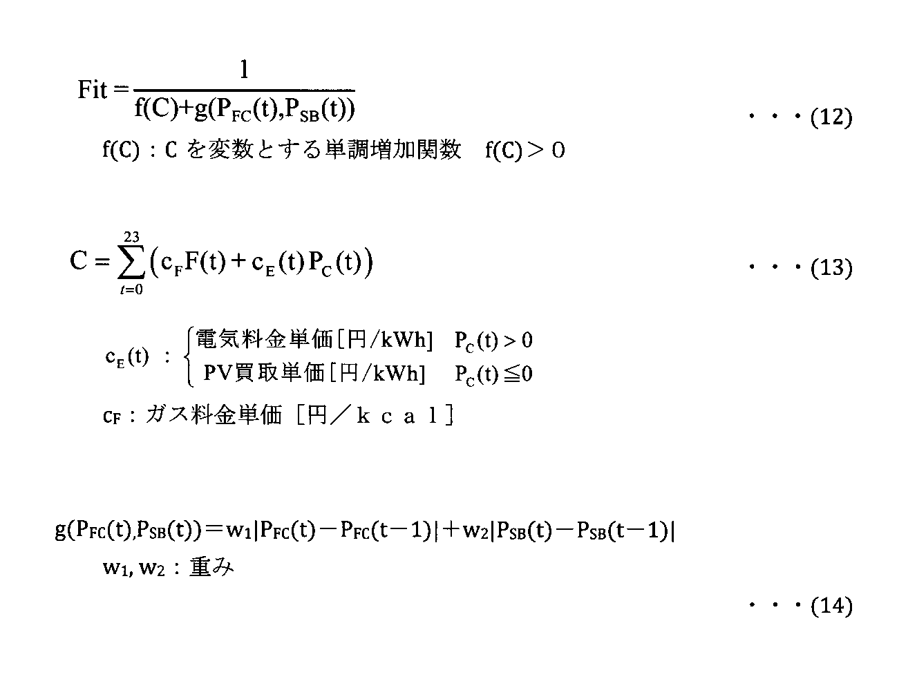
Equation (12) shows the fitness Fit to be maximized. By optimizing this Fit as an objective function, the driving schedule can be calculated. Formula (13) shows the utility cost balance C. Equation (14) represents the cost g (P FC , P SB ) required for discontinuity in device operation. The total sum from t = 0 to t = 23 in the utility bill C is equivalent to obtaining the sum over 24 hours.
式(12)に示される適合度Fitは、1日あたりの光熱費収支Cを変数とする単調増加関数f(C)と機器稼動の不連続性に掛かるコストg(PFC,PSB)>0との和の、逆数である。PV発電量がホーム100の電力デマンドを大きく上回ると光熱費収支Cが負になることがあるので、光熱費収支Cの減少と適合度Fitの増加とを対応させるために、式(12)のフォームが採用される。第1の実施形態ではf(C)>0となる関数が用いられる。
The fitness Fit shown in the equation (12) is a monotonically increasing function f (C) having a utility cost C per day as a variable and a cost g (P FC , P SB ) required for discontinuity in equipment operation> The reciprocal of the sum with zero. If the PV power generation amount greatly exceeds the power demand of the home 100, the utility bill C may become negative. Therefore, in order to correspond to the decrease in the utility bill C and the increase in fitness Fit, A form is adopted. In the first embodiment, a function satisfying f (C)> 0 is used.
以上の式に、電力デマンド、給湯デマンド、PV発電量、太陽熱温水量、電気料金単価、ガス料金単価、およびPV買取価格を与え、突然変異、交差、淘汰など、遺伝的操作を繰り返してFitを最大化する。このような操作により、光熱費収支Cを最適化し得る、FCユニット103の発電量PFC(t)の系列と、蓄電池102の充放電PSB(t)の系列とを求めることが可能になる。
Give power demand, hot water demand, PV power generation amount, solar hot water amount, electricity unit price, gas unit price, and PV purchase price to the above formula, and repeat genetic operations such as mutation, crossing, dredging, etc. maximize. By such an operation, it becomes possible to obtain a series of power generation amount P FC (t) of the FC unit 103 and a series of charge / discharge P SB (t) of the storage battery 102 that can optimize the utility bill C. .
図7は、第1の実施形態に係る最適化演算の流れの一例を示すフローチャートである。最適化アルゴリズムの一例として遺伝的アルゴリズムを採りあげる。以下、遺伝的アルゴリズムに基づく処理手順につき説明する。
(ステップS2-1) 初期個体群の生成
このステップにおいて、計算部300cは、n個の初期個体を発生させる。個体の遺伝子は、例えば時刻tでのFCユニット103の運転・停止、FCユニット103の発電量、蓄電池102の充放電電力などである。遺伝子列として例えば1日分(24時間分)を設けることができる。それぞれの個体は、FCユニット103、蓄電池102の各遺伝子列の集合である。制約条件を満足しない固体は遺伝子をビット反転させて、制約条件を満足させるように改変する。 FIG. 7 is a flowchart illustrating an example of the flow of the optimization calculation according to the first embodiment. A genetic algorithm is taken as an example of an optimization algorithm. The processing procedure based on the genetic algorithm will be described below.
(Step S2-1) Generation of initial population In this step, thecalculation unit 300c generates n initial individuals. The individual gene includes, for example, operation / stop of the FC unit 103 at time t, power generation amount of the FC unit 103, charge / discharge power of the storage battery 102, and the like. For example, one day (24 hours) can be provided as a gene string. Each individual is a set of gene sequences of the FC unit 103 and the storage battery 102. Solids that do not satisfy the constraint condition are bit-inverted to modify the gene to satisfy the constraint condition.
(ステップS2-1) 初期個体群の生成
このステップにおいて、計算部300cは、n個の初期個体を発生させる。個体の遺伝子は、例えば時刻tでのFCユニット103の運転・停止、FCユニット103の発電量、蓄電池102の充放電電力などである。遺伝子列として例えば1日分(24時間分)を設けることができる。それぞれの個体は、FCユニット103、蓄電池102の各遺伝子列の集合である。制約条件を満足しない固体は遺伝子をビット反転させて、制約条件を満足させるように改変する。 FIG. 7 is a flowchart illustrating an example of the flow of the optimization calculation according to the first embodiment. A genetic algorithm is taken as an example of an optimization algorithm. The processing procedure based on the genetic algorithm will be described below.
(Step S2-1) Generation of initial population In this step, the
(ステップS2-2)
ステップS2-2のループは、ステップS2-3~S2-6の処理を繰り返す処理である。このループが規定回数になれば、アルゴリズム演算が終了する。また、各個体の適合度およびその世代での平均適合度が計算される。その世代における平均適応度は前2世代の平均適応度と比較される。比較の結果が任意に設定された値ε以下であれば、アルゴリズム演算が終了する。 (Step S2-2)
The loop of step S2-2 is a process of repeating the processes of steps S2-3 to S2-6. When this loop reaches the specified number of times, the algorithm operation is finished. In addition, the fitness of each individual and the average fitness of the generation are calculated. The average fitness in that generation is compared with the average fitness of the previous two generations. If the result of the comparison is less than or equal to the arbitrarily set value ε, the algorithm operation is terminated.
このステップにおいて、計算部300cは、制約条件を満足しない個体を排除する。よって、制約条件を満足しない個体は淘汰される。既定数以上の個体が存在する場合には適応度の悪い(適応度の小さい)個体を排除して、個体の数を既定数以下に保つようにする。
In this step, the calculation unit 300c excludes individuals that do not satisfy the constraint conditions. Therefore, individuals who do not satisfy the constraints are deceived. If there are more than a predetermined number of individuals, individuals with poor fitness (small fitness) are excluded, and the number of individuals is kept below the predetermined number.
(ステップS2-4) 増殖
このステップにおいて、個体数が予め定義した個体数より少ない場合には、計算部300cは、適応度が最良の個体を増殖させる。 (Step S2-4) Proliferation In this step, when the number of individuals is smaller than the number of individuals defined in advance, thecalculation unit 300c proliferates individuals with the best fitness.
このステップにおいて、個体数が予め定義した個体数より少ない場合には、計算部300cは、適応度が最良の個体を増殖させる。 (Step S2-4) Proliferation In this step, when the number of individuals is smaller than the number of individuals defined in advance, the
(ステップS2-5) 交叉
計算部300cは、ランダムにペアリングを行う。ペアリングは全個体数に対する割合(交叉率)分だけ行い、各ペアごとにランダムに遺伝子座を選び、一点交叉させる。 (Step S2-5)Crossover Calculation unit 300c performs pairing at random. Pairing is performed as much as the ratio (crossover rate) to the total number of individuals, and gene loci are randomly selected for each pair and crossed at one point.
計算部300cは、ランダムにペアリングを行う。ペアリングは全個体数に対する割合(交叉率)分だけ行い、各ペアごとにランダムに遺伝子座を選び、一点交叉させる。 (Step S2-5)
(ステップS2-6) 突然変異
このステップにおいて、計算部300cは、全個体数に対する割合(突然変異率)分だけランダムに個体を選び、各個体の任意(ランダムに決定する)の遺伝子座の遺伝子をビット反転させる。 (Step S2-6) Mutation In this step, thecalculation unit 300c randomly selects individuals by a ratio (mutation rate) with respect to the total number of individuals, and genes at arbitrary (determined randomly) loci of each individual. Invert the bit.
このステップにおいて、計算部300cは、全個体数に対する割合(突然変異率)分だけランダムに個体を選び、各個体の任意(ランダムに決定する)の遺伝子座の遺伝子をビット反転させる。 (Step S2-6) Mutation In this step, the
(ステップS2-3)~(ステップS2-6)の手順は、世代数<最大世代数の条件が満たされるまで、世代数をインクリメントしつつ繰り返される(ステップS2-2のループ)。この条件が満たされれば、計算部300cは結果を出力し(ステップS2-7)、計算手順を終了する。
The procedure from (Step S2-3) to (Step S2-6) is repeated while incrementing the number of generations until the condition of the number of generations <the maximum number of generations is satisfied (loop of Step S2-2). If this condition is satisfied, the calculation unit 300c outputs the result (step S2-7) and ends the calculation procedure.
図8は、第1の実施形態により得られる効果を説明するための図である。図8はホーム100の1日の電力デマンドと給湯デマンドの各予測結果に基づき算出された、蓄電池102およびFCユニット103の1日分の運転スケジュールの一例を示す。電気料金単価は7:00から23:00までが28円/kWh、23:00から翌日7:00までが9円/kWhの昼夜別料金を想定した。図8においては売電による光熱費収支の改善については想定せず、電力デマンド、給湯デマンドと電気、ガスの料金単価のみを用いた計算結果を示す。
FIG. 8 is a diagram for explaining the effects obtained by the first embodiment. FIG. 8 shows an example of an operation schedule for one day of the storage battery 102 and the FC unit 103 calculated based on the prediction results of the daily power demand and hot water supply demand of the home 100. The unit price of electricity was assumed to be 28 yen / kWh from 7:00 to 23:00 and 9 yen / kWh from 23:00 to 7:00 the next day. In FIG. 8, the calculation result using only the electric power demand, the hot water supply demand, the electricity, and the gas unit price is shown without assuming the improvement of the utility bill due to the power sale.
蓄電池102の運転スケジュールは、電気料金単価の安い時間帯(0:00~6:00)に充電し、電気料金単価の高い時間帯(7:00~10:00、13:00~22:00)に放電するようになっている。これにより、電気料金単価の高い時間帯の購入電力が減るので電気代を減らすことできる。
The operation schedule of the storage battery 102 is charged in a time zone where the unit price of electricity is low (from 0:00 to 6:00), and a time zone where the unit price of electricity is high (from 7:00 to 10:00, from 13:00 to 22:00). ) To discharge. Thereby, since the purchased electric power in the time zone with a high electricity bill unit price decreases, an electricity bill can be reduced.
FCユニット103は最大出力で運転し、発電量が電力デマンドを上回る時間帯(12:00~14:00)は余剰発電量が蓄電池102に充電される。よって発電された電力が逆潮流防止ヒータ222で無駄に消費(廃棄)されることを防止でき、ガス代も削減することが可能になる。逆潮流防止ヒータ222は、24時間に渡って稼働することなく推移していることが理解される。
The FC unit 103 is operated at the maximum output, and the surplus power generation amount is charged in the storage battery 102 during a time period (12:00 to 14:00) when the power generation amount exceeds the power demand. Therefore, it is possible to prevent the generated power from being consumed (discarded) wastefully by the reverse flow prevention heater 222, and it is possible to reduce gas costs. It is understood that the reverse power flow prevention heater 222 has changed without operating for 24 hours.
また図8には、時間ごとの総貯湯量の推移をカロリーベースで示すグラフが示される。このグラフは、貯湯槽223における例えば45°C以上の湯量と、太陽熱温水器106にプールされる同温度の湯量との合計を示す。このグラフは基本的にはPV発電量と同様の日内変動を示すが、FCユニット103の稼動状態と給湯デマンドの変化に応じても変化する。
Also, FIG. 8 shows a graph showing the transition of the total hot water storage amount by time on a calorie basis. This graph shows the sum of the amount of hot water of, for example, 45 ° C. or more in the hot water storage tank 223 and the amount of hot water of the same temperature pooled in the solar water heater 106. This graph basically shows daily fluctuations similar to the PV power generation amount, but also changes according to changes in the operating state of the FC unit 103 and hot water supply demand.
以上述べたように第1の実施形態では、ホーム100におけるPV発電量、電力デマンド、給湯デマンドおよび太陽熱温水量を予測する。そして、各予測値に基づいて、予め設定された制約条件下で評価関数を最小化する最適化計算を実行することで、エネルギーコスト(光熱費)を最小化すべくエネルギー管理を行う。つまり、FCユニット103の発電量を可変とし太陽熱温水量を組み込んだ制御モデル、に基づいて、FCユニット103の運転スケジュールおよび蓄電池102の充放電スケジュールを最適化するようにしている。これにより逆潮流防止ヒータ222を無駄に稼動させず、光熱費を安くすることの可能なスケジュールを作成することが可能になる。
As described above, in the first embodiment, the PV power generation amount, power demand, hot water supply demand, and solar hot water amount in the home 100 are predicted. Then, based on each predicted value, energy management is performed so as to minimize the energy cost (utilization cost) by executing an optimization calculation that minimizes the evaluation function under preset constraint conditions. That is, the operation schedule of the FC unit 103 and the charge / discharge schedule of the storage battery 102 are optimized based on a control model in which the power generation amount of the FC unit 103 is variable and the amount of solar hot water is incorporated. As a result, it is possible to create a schedule that can reduce the utility cost without wastefully operating the reverse power flow prevention heater 222.
式(12)、(13)に示されるように、最大化すべき適合度Fitを示す関数が、FCユニット103の稼働に要するガス料金を含む。これにより、可能な解が存在するという条件下で、逆潮流防止ヒータ222を無駄に動作させるスケジュールは最適化計算の過程で淘汰される。
As shown in the equations (12) and (13), the function indicating the fitness Fit to be maximized includes the gas charge required for the operation of the FC unit 103. Thus, a schedule for operating the reverse flow prevention heater 222 in vain under the condition that a possible solution exists is deceived in the process of optimization calculation.
また、式(10)に示されるように、或る時刻t-1から次の時刻tまでのFCユニット103の発電量の変化量を、-PFC_DOWN(FCユニット103の発電量の減少速度の下限値)からPFC_UP(FCユニット103の発電量の増加速度の上限値)の範囲に収めるという、制約条件を設けるようにした。これにより、FCユニット103の発電量の変化量が電力デマンドへの追従能力を超えないような発電スケジュールを作成することが可能となる。つまりこの制約条件により、電力デマンドへの追従能力を超えない範囲で、FCユニット103の発電スケジュールを作成することが可能になる。すなわちFCユニット103を、HEMSの作成した発電スケジュールに従って稼働させることが可能になる。
Further, as shown in Expression (10), the amount of change in the power generation amount of the FC unit 103 from a certain time t−1 to the next time t is expressed as −P FC_DOWN (the decrease rate of the power generation amount of the FC unit 103). A constraint condition is set such that it falls within the range of (lower limit value) to P FC_UP (upper limit value of the increase rate of power generation amount of the FC unit 103). Thereby, it is possible to create a power generation schedule such that the amount of change in the power generation amount of the FC unit 103 does not exceed the ability to follow the power demand. In other words, this constraint condition makes it possible to create a power generation schedule for the FC unit 103 within a range that does not exceed the ability to follow the power demand. That is, the FC unit 103 can be operated according to the power generation schedule created by the HEMS.
特に、ステップS1-2の予測手順と、ステップS1-3の最適スケジューリング(図5)とを組み合せることで、一日分程度のまとまった期間の電力デマンド予測、給湯デマンド予測、PV発電予測および太陽熱温水量予測に応じて、FCユニット103の発電スケジュールや蓄電池102の充放電スケジュールといった需給計画を、全体のバランスを考慮したうえで作成できるようになる。
In particular, by combining the prediction procedure of step S1-2 and the optimal scheduling (FIG. 5) of step S1-3, power demand prediction, hot water supply demand prediction, PV power generation prediction, According to the solar hot water amount prediction, a supply and demand plan such as a power generation schedule of the FC unit 103 and a charge / discharge schedule of the storage battery 102 can be created in consideration of the overall balance.
従って、蓄電池102が満充電であるためにFCユニット103の余剰電力を充電できないケースや、蓄電池102から放電すべきときに充電残量が足りないといったケースを回避することが可能になる。
Therefore, it is possible to avoid the case where the storage battery 102 is fully charged and therefore the surplus power of the FC unit 103 cannot be charged, and the case where the remaining charge is insufficient when the storage battery 102 should be discharged.
以上から第1の実施形態によれば、商用電力系統に逆潮流できない余剰電力を無駄に消費することなく、有効に利用することが可能になる。これらのことから、余剰電力が無駄に消費されることを防止可能なエネルギー管理システム、エネルギー管理方法、プログラムおよびサーバを提供することが可能になる。
As described above, according to the first embodiment, it is possible to effectively use surplus power that cannot reversely flow into the commercial power system without wasting it. Accordingly, it is possible to provide an energy management system, an energy management method, a program, and a server that can prevent excess power from being wasted.
[第2の実施形態]
図9は、第2の実施形態に係るHEMSの要部を示す機能ブロック図である。図9において図3と共通する部分には同じ符号を付して示し、ここでは異なる部分についてのみ説明する。第2の実施形態では、FCユニット103に代えて、地中熱エネルギーを利用するヒートポンプ式給湯器(HP)110を併用するケースを想定する。ヒートポンプ式給湯器110は、最適化された運転スケジュールに基づいて制御部300dにより制御される。 [Second Embodiment]
FIG. 9 is a functional block diagram illustrating a main part of the HEMS according to the second embodiment. In FIG. 9, the same reference numerals are given to the portions common to FIG. 3, and only different portions will be described here. In 2nd Embodiment, it replaces withFC unit 103 and assumes the case where the heat pump type hot water heater (HP) 110 which uses underground thermal energy is used together. The heat pump hot water heater 110 is controlled by the control unit 300d based on the optimized operation schedule.
図9は、第2の実施形態に係るHEMSの要部を示す機能ブロック図である。図9において図3と共通する部分には同じ符号を付して示し、ここでは異なる部分についてのみ説明する。第2の実施形態では、FCユニット103に代えて、地中熱エネルギーを利用するヒートポンプ式給湯器(HP)110を併用するケースを想定する。ヒートポンプ式給湯器110は、最適化された運転スケジュールに基づいて制御部300dにより制御される。 [Second Embodiment]
FIG. 9 is a functional block diagram illustrating a main part of the HEMS according to the second embodiment. In FIG. 9, the same reference numerals are given to the portions common to FIG. 3, and only different portions will be described here. In 2nd Embodiment, it replaces with
図10は、第2の実施形態に係る制御対象モデル300gについて説明するための図である。図4と比較して、FC本体220がヒートポンプ式給湯器110に置き換わる。ヒートポンプ式給湯器110はFCユニット103に比べて制御の応答性に優れるので、逆潮流防止ヒータ222を排除することが可能である。次式(15)~(22)に、図10における各変量の関係が示される。

FIG. 10 is a diagram for explaining a control target model 300g according to the second embodiment. Compared with FIG. 4, the FC main body 220 is replaced with a heat pump type water heater 110. Since the heat pump type hot water heater 110 is superior in control responsiveness compared to the FC unit 103, the reverse power flow prevention heater 222 can be eliminated. The following equations (15) to (22) show the relationship between the variables in FIG.
新たな変量PHP(t)、QHP(t)は以下に示される。

The new variables P HP (t) and Q HP (t) are shown below.
図10に示される制御対象モデルを用い、上記された各変量を用いて第1の実施形態と同様に最適化を実行することで運転スケジュールを算出することが可能である。その詳細については第1の実施形態と同様であるので、煩雑を避けるために説明を省略する。
It is possible to calculate an operation schedule by executing optimization using the controlled object model shown in FIG. 10 and using the variables described above in the same manner as in the first embodiment. Details thereof are the same as those in the first embodiment, and thus description thereof is omitted to avoid complication.
第2の実施形態ではヒートポンプ式給湯器110が最適化計算に組み入れられる。すなわち作成部300cは、ホーム100の電力デマンド予測および給湯デマンド予測と、地中熱エネルギーとに基づいて評価関数を最小化すべく最適化計算を実施し、運転スケジュールを作成する。第2の実施形態によれば、FCユニット103の燃料が不要になるので、さらなるコストメリットを得ることが可能になる。
In the second embodiment, the heat pump type water heater 110 is incorporated in the optimization calculation. That is, the creation unit 300c performs an optimization calculation to minimize the evaluation function based on the power demand prediction and hot water supply demand prediction of the home 100 and the underground heat energy, and creates an operation schedule. According to the second embodiment, since the fuel of the FC unit 103 is not necessary, further cost merit can be obtained.
なお本発明は上記実施形態に限定されるものではない。例えば実施形態では遺伝的アルゴリズムを利用することについて説明したが、運転スケジュールを算出するための解法として遺伝的アルゴリズムは唯一のものではない。他の種々のアルゴリズムを用いて最適な運転スケジュールを算出することが可能である。
The present invention is not limited to the above embodiment. For example, in the embodiment, the use of the genetic algorithm has been described, but the genetic algorithm is not the only solution for calculating the driving schedule. It is possible to calculate an optimal driving schedule using various other algorithms.
また実施形態では、太陽熱温水器から給湯配管に直接、給湯するケースを説明した。これに限らず、太陽熱温水器からの温水をヒートポンプ式給湯器に給水する配水ルートを設けても良い。このような構成は日射量の少ない冬季や寒冷地においては有利である。
In the embodiment, the case where hot water is supplied directly from the solar water heater to the hot water supply pipe has been described. Not limited to this, a water distribution route for supplying hot water from the solar water heater to the heat pump hot water heater may be provided. Such a configuration is advantageous in winter and cold regions where the amount of solar radiation is small.
さらに、浴槽の残り湯から熱交換器で熱を回収し、太陽熱温水器からの温水、あるいはヒートポンプ式給湯器からの温水を、回収された熱で加温するようにしても良い。つまり、給湯器から供給される温水と浴槽内の温水との間で熱エネルギーを交換する熱交換器をホーム100に備えてもよい。このケースでは、作成部300cは、予測されたエネルギーデマンド、エネルギー供給量、および熱エネルギーに基づいて運転スケジュールが作成される。
Furthermore, heat may be recovered from the remaining hot water in the bathtub using a heat exchanger, and hot water from a solar water heater or hot water from a heat pump water heater may be heated with the recovered heat. That is, the home 100 may be provided with a heat exchanger that exchanges heat energy between the hot water supplied from the water heater and the hot water in the bathtub. In this case, the creation unit 300c creates an operation schedule based on the predicted energy demand, energy supply amount, and thermal energy.
さらに、ユーザインタフェース105aに、太陽熱エネルギーや地中熱エネルギーなどの、外部からの熱収支に関する情報を表示するようにしてもよい。このようにすれば、電力エネルギーだけに着目しがちなユーザに熱エネルギーを意識させることが可能になる。
Furthermore, information regarding the heat balance from the outside, such as solar thermal energy and underground thermal energy, may be displayed on the user interface 105a. In this way, it is possible to make the user who tends to focus only on power energy aware of thermal energy.
本発明のいくつかの実施形態を説明したが、これらの実施形態は例として提示するものであり、発明の範囲を限定することは意図していない。これら新規な実施形態は、その他の様々な形態で実施されることが可能であり、発明の要旨を逸脱しない範囲で、種々の省略、置き換え、変更を行うことができる。これら実施形態やその変形は、発明の範囲や要旨に含まれるとともに、特許請求の範囲に記載された発明とその均等の範囲に含まれる。
Although several embodiments of the present invention have been described, these embodiments are presented as examples and are not intended to limit the scope of the invention. These novel embodiments can be implemented in various other forms, and various omissions, replacements, and changes can be made without departing from the scope of the invention. These embodiments and modifications thereof are included in the scope and gist of the invention, and are included in the invention described in the claims and the equivalents thereof.
Claims (26)
- 再生可能エネルギーを熱源とする給湯器を備える需要家のエネルギーを管理するエネルギー管理システムであって、
前記給湯器、発電装置、蓄電装置およびエネルギー消費機器を含むエネルギー関連機器に係わるデータを前記需要家から取得する取得部と、
前記取得されたデータに基づいて前記需要家におけるエネルギーデマンドおよびエネルギー供給量を予測する予測部と、
前記蓄電装置の満充電に伴い破棄される余剰電力を最小化する条件下で、前記需要家におけるエネルギーコストを最小化すべく、前記予測されたエネルギーデマンドおよびエネルギー供給量に基づいて前記エネルギー関連機器の運転スケジュールを作成する作成部と、
前記作成された運転スケジュールに基づいて前記エネルギー関連機器を制御する制御部とを具備することを特徴とする、エネルギー管理システム。 An energy management system for managing energy of a customer having a water heater that uses renewable energy as a heat source,
An acquisition unit for acquiring data related to energy-related equipment including the water heater, power generation device, power storage device, and energy consuming equipment from the consumer;
A prediction unit that predicts energy demand and energy supply amount in the consumer based on the acquired data;
In order to minimize the energy cost at the consumer under the condition of minimizing the surplus power discarded when the power storage device is fully charged, the energy related device is configured based on the predicted energy demand and energy supply amount. A creation section for creating an operation schedule;
And a control unit that controls the energy-related equipment based on the created operation schedule. - 前記作成部は、前記給湯器を含む前記需要家の制御対象モデルに基づいて前記運転スケジュールを作成することを特徴とする、請求項1に記載のエネルギー管理システム。 The energy management system according to claim 1, wherein the creation unit creates the operation schedule based on a control target model of the customer including the water heater.
- 前記制御対象モデルは、さらに、電力系統、燃料電池、補助ボイラ、逆潮流防止ヒータ、前記蓄電装置、貯湯槽の少なくともいずれか1つを含み、
前記作成部は、前記制御対象モデルに係わる変量を含む目的関数を最適化して前記運転スケジュールを作成することを特徴とする、請求項2に記載のエネルギー管理システム。 The controlled object model further includes at least one of an electric power system, a fuel cell, an auxiliary boiler, a reverse power flow prevention heater, the power storage device, and a hot water storage tank,
The energy management system according to claim 2, wherein the creation unit creates the operation schedule by optimizing an objective function including a variable related to the control target model. - 前記目的関数は、電気料金、ガス料金および売電価格を変数として含むことを特徴とする、請求項3に記載のエネルギー管理システム。 The energy management system according to claim 3, wherein the objective function includes an electricity charge, a gas charge, and a power sale price as variables.
- 前記作成部は、前記目的関数を遺伝的アルゴリズムにより最適化することを特徴とする、請求項3および4のいずれか1項に記載のエネルギー管理システム。 The energy management system according to any one of claims 3 and 4, wherein the creation unit optimizes the objective function by a genetic algorithm.
- 前記発電装置は燃料電池であり、
前記作成部は、前記燃料電池の発電量の時間に対する変化を既定の範囲内に制限することを含む条件下で前記運転スケジュールを作成することを特徴とする、請求項1に記載のエネルギー管理システム。 The power generator is a fuel cell;
2. The energy management system according to claim 1, wherein the creation unit creates the operation schedule under a condition including limiting a change in power generation amount of the fuel cell with respect to time within a predetermined range. . - 前記給湯器から供給される温水と浴槽内の温水との間で熱エネルギーを交換する熱交換器を前記需要家が備える場合に、
前記作成部は、前記予測されたエネルギーデマンドとエネルギー供給量、および前記熱エネルギーに基づいて前記運転スケジュールを作成することを特徴とする、請求項1に記載のエネルギー管理システム。 When the consumer is equipped with a heat exchanger that exchanges thermal energy between hot water supplied from the water heater and hot water in the bathtub,
The energy management system according to claim 1, wherein the creation unit creates the operation schedule based on the predicted energy demand and energy supply amount and the thermal energy. - 前記給湯器は、地中熱エネルギーを利用するヒートポンプ式給湯器であり、
前記作成部は、前記予測されたエネルギーデマンドとエネルギー供給量、および前記地中熱エネルギーに基づいて前記運転スケジュールを作成することを特徴とする、請求項1に記載のエネルギー管理システム。 The water heater is a heat pump type water heater that uses underground heat energy,
The energy management system according to claim 1, wherein the creation unit creates the operation schedule based on the predicted energy demand and energy supply amount, and the geothermal energy. - さらに、前記運転スケジュールにユーザの意思を反映させるためのインタフェース部を備えることを特徴とする、請求項1に記載のエネルギー管理システム。 The energy management system according to claim 1, further comprising an interface unit for reflecting a user's intention in the operation schedule.
- 前記取得部、前記予測部、前記作成部、および前記制御部の少なくともいずれか1つは、クラウドコンピューティングシステムに配置される機能オブジェクトであることを特徴とする、請求項1に記載のエネルギー管理システム。 The energy management according to claim 1, wherein at least one of the acquisition unit, the prediction unit, the creation unit, and the control unit is a functional object arranged in a cloud computing system. system.
- 再生可能エネルギーを熱源とする給湯器を備える需要家のエネルギーを管理するエネルギー管理方法であって、
前記給湯器、発電装置、蓄電装置およびエネルギー消費機器を含むエネルギー関連機器に係わるデータを前記需要家から取得し、
前記取得されたデータに基づいて前記需要家におけるエネルギーデマンドおよびエネルギー供給量を予測し、
前記蓄電装置の満充電に伴い破棄される余剰電力を最小化する条件下で、前記需要家におけるエネルギーコストを最小化すべく、前記予測されたエネルギーデマンドおよびエネルギー供給量に基づいて前記エネルギー関連機器の運転スケジュールを作成し、
前記作成された運転スケジュールに基づいて前記エネルギー関連機器を制御することを特徴とする、エネルギー管理方法。 An energy management method for managing energy of a customer having a water heater that uses renewable energy as a heat source,
Obtaining data related to energy-related equipment including the water heater, power generator, power storage device and energy consuming equipment from the consumer,
Predicting energy demand and energy supply at the consumer based on the acquired data;
In order to minimize the energy cost at the consumer under the condition of minimizing the surplus power discarded when the power storage device is fully charged, the energy related device is configured based on the predicted energy demand and energy supply amount. Create a driving schedule,
An energy management method, wherein the energy-related device is controlled based on the created operation schedule. - 前記給湯器を含む前記需要家の制御対象モデルに基づいて前記運転スケジュールを作成することを特徴とする、請求項11に記載のエネルギー管理方法。 The energy management method according to claim 11, wherein the operation schedule is created based on a model to be controlled by the consumer including the water heater.
- 前記制御対象モデルは、さらに、電力系統、燃料電池、補助ボイラ、逆潮流防止ヒータ、前記蓄電装置、貯湯槽の少なくともいずれか1つを含み、
前記制御対象モデルに係わる変量を含む目的関数を最適化して前記運転スケジュールを作成することを特徴とする、請求項12に記載のエネルギー管理方法。 The controlled object model further includes at least one of an electric power system, a fuel cell, an auxiliary boiler, a reverse power flow prevention heater, the power storage device, and a hot water storage tank,
The energy management method according to claim 12, wherein the operation schedule is created by optimizing an objective function including a variable related to the controlled object model. - 前記目的関数は、電気料金、ガス料金および売電価格を変数として含むことを特徴とする、請求項13に記載のエネルギー管理方法。 14. The energy management method according to claim 13, wherein the objective function includes an electricity charge, a gas charge, and a power sale price as variables.
- 前記目的関数を遺伝的アルゴリズムにより最適化することを特徴とする、請求項13および14のいずれか1項に記載のエネルギー管理方法。 The energy management method according to any one of claims 13 and 14, wherein the objective function is optimized by a genetic algorithm.
- 前記発電装置は燃料電池であり、
前記燃料電池の発電量の時間に対する変化を既定の範囲内に制限することを含む条件下で前記運転スケジュールを作成することを特徴とする、請求項11に記載のエネルギー管理方法。 The power generator is a fuel cell;
The energy management method according to claim 11, wherein the operation schedule is created under a condition including limiting a change of the power generation amount of the fuel cell with respect to time within a predetermined range. - 前記給湯器から供給される温水と浴槽内の温水との間で熱エネルギーを交換する熱交換器を前記需要家が備える場合に、前記予測されたエネルギーデマンドとエネルギー供給量、および前記熱エネルギーに基づいて前記運転スケジュールを作成することを特徴とする、請求項11に記載のエネルギー管理方法。 When the consumer includes a heat exchanger for exchanging heat energy between hot water supplied from the water heater and hot water in the bathtub, the predicted energy demand and energy supply amount, and the heat energy The energy management method according to claim 11, wherein the operation schedule is created based on the energy management schedule.
- 前記給湯器は、地中熱エネルギーを利用するヒートポンプ式給湯器であり、
前記予測されたエネルギーデマンドとエネルギー供給量、および前記地中熱エネルギーに基づいて前記運転スケジュールを作成することを特徴とする、請求項11に記載のエネルギー管理方法。 The water heater is a heat pump type water heater that uses underground heat energy,
The energy management method according to claim 11, wherein the operation schedule is created based on the predicted energy demand and energy supply amount, and the geothermal energy. - 請求項11乃至18のいずれか1項に記載の方法をコンピュータに実行させるための命令を含むことを特徴とする、プログラム。 A program comprising instructions for causing a computer to execute the method according to any one of claims 11 to 18.
- 再生可能エネルギーを熱源とする給湯器を備える需要家のクライアント装置と通信可能なサーバであって、
前記給湯器、発電装置、蓄電装置およびエネルギー消費機器を含むエネルギー関連機器に係わるデータを前記クライアント装置から取得する取得部と、
前記取得されたデータに基づいて前記需要家におけるエネルギーデマンドおよびエネルギー供給量を予測する予測部と、
前記蓄電装置の満充電に伴い破棄される余剰電力を最小化する条件下で、前記需要家におけるエネルギーコストを最小化すべく、前記予測されたエネルギーデマンドおよびエネルギー供給量に基づいて前記エネルギー関連機器の運転スケジュールを作成する作成部と、
前記作成された運転スケジュールに基づいて前記エネルギー関連機器を制御するための制御情報を前記クライアント装置に送信する制御部とを具備することを特徴とする、サーバ。 A server capable of communicating with a client device of a customer having a water heater that uses renewable energy as a heat source,
An acquisition unit for acquiring data related to energy-related devices including the water heater, power generation device, power storage device and energy consuming device from the client device;
A prediction unit that predicts energy demand and energy supply amount in the consumer based on the acquired data;
In order to minimize the energy cost at the consumer under the condition of minimizing the surplus power discarded when the power storage device is fully charged, the energy related device is configured based on the predicted energy demand and energy supply amount. A creation section for creating an operation schedule;
And a control unit that transmits control information for controlling the energy-related device to the client device based on the created operation schedule. - 前記作成部は、前記給湯器を含む前記需要家の制御対象モデルに基づいて前記運転スケジュールを作成することを特徴とする、請求項20に記載のサーバ。 The server according to claim 20, wherein the creating unit creates the operation schedule based on a control target model of the customer including the water heater.
- 前記制御対象モデルは、さらに、電力系統、燃料電池、補助ボイラ、逆潮流防止ヒータ、前記蓄電装置、貯湯槽の少なくともいずれか1つを含み、
前記作成部は、前記制御対象モデルに係わる変量を含む目的関数を最適化して前記運転スケジュールを作成することを特徴とする、請求項21に記載のサーバ。 The controlled object model further includes at least one of an electric power system, a fuel cell, an auxiliary boiler, a reverse power flow prevention heater, the power storage device, and a hot water storage tank,
The server according to claim 21, wherein the creating unit creates the operation schedule by optimizing an objective function including a variable related to the control target model. - 前記作成部は、前記目的関数を遺伝的アルゴリズムにより最適化することを特徴とする、請求項22に記載のサーバ。 The server according to claim 22, wherein the creating unit optimizes the objective function using a genetic algorithm.
- 前記発電装置は燃料電池であり、
前記作成部は、前記燃料電池の発電量の時間に対する変化を既定の範囲内に制限することを含む条件下で前記運転スケジュールを作成することを特徴とする、請求項20に記載のサーバ。 The power generator is a fuel cell;
21. The server according to claim 20, wherein the creation unit creates the operation schedule under a condition including limiting a change of the power generation amount of the fuel cell with respect to time within a predetermined range. - 前記給湯器から供給される温水と浴槽内の温水との間で熱エネルギーを交換する熱交換器を前記需要家が備える場合に、
前記作成部は、前記予測されたエネルギーデマンドとエネルギー供給量、および前記熱エネルギーに基づいて前記運転スケジュールを作成することを特徴とする、請求項20に記載のサーバ。 When the consumer is equipped with a heat exchanger that exchanges thermal energy between hot water supplied from the water heater and hot water in the bathtub,
The server according to claim 20, wherein the creating unit creates the operation schedule based on the predicted energy demand and energy supply amount and the thermal energy. - 前記給湯器は、地中熱エネルギーを利用するヒートポンプ式給湯器であり、
前記作成部は、前記予測されたエネルギーデマンドとエネルギー供給量、および前記地中熱エネルギーに基づいて前記運転スケジュールを作成することを特徴とする、請求項20に記載のサーバ。 The water heater is a heat pump type water heater that uses underground heat energy,
The server according to claim 20, wherein the creating unit creates the operation schedule based on the predicted energy demand and energy supply amount, and the geothermal energy.
Priority Applications (2)
| Application Number | Priority Date | Filing Date | Title |
|---|---|---|---|
| EP13824085.8A EP2966748A4 (en) | 2013-03-07 | 2013-12-09 | Energy management system, energy management method, program, and server |
| US14/170,112 US20140257584A1 (en) | 2013-03-07 | 2014-01-31 | Energy management system, energy management method, medium, and server |
Applications Claiming Priority (2)
| Application Number | Priority Date | Filing Date | Title |
|---|---|---|---|
| JP2013045471A JP6009976B2 (en) | 2013-03-07 | 2013-03-07 | Energy management system, energy management method, program, and server |
| JP2013-045471 | 2013-03-07 |
Related Child Applications (1)
| Application Number | Title | Priority Date | Filing Date |
|---|---|---|---|
| US14/170,112 Continuation US20140257584A1 (en) | 2013-03-07 | 2014-01-31 | Energy management system, energy management method, medium, and server |
Publications (1)
| Publication Number | Publication Date |
|---|---|
| WO2014136341A1 true WO2014136341A1 (en) | 2014-09-12 |
Family
ID=51490884
Family Applications (1)
| Application Number | Title | Priority Date | Filing Date |
|---|---|---|---|
| PCT/JP2013/082978 WO2014136341A1 (en) | 2013-03-07 | 2013-12-09 | Energy management system, energy management method, program, and server |
Country Status (3)
| Country | Link |
|---|---|
| EP (1) | EP2966748A4 (en) |
| JP (1) | JP6009976B2 (en) |
| WO (1) | WO2014136341A1 (en) |
Cited By (3)
| Publication number | Priority date | Publication date | Assignee | Title |
|---|---|---|---|---|
| CN105337273A (en) * | 2015-09-18 | 2016-02-17 | 北京德意新能电气有限公司 | Electric energy integration interconnection system suitable for smart power grid |
| CN115848196A (en) * | 2022-12-07 | 2023-03-28 | 南通国轩新能源科技有限公司 | Electric automobile ordered charging guide method based on dynamic demand and new energy consumption |
| US11875371B1 (en) | 2017-04-24 | 2024-01-16 | Skyline Products, Inc. | Price optimization system |
Families Citing this family (8)
| Publication number | Priority date | Publication date | Assignee | Title |
|---|---|---|---|---|
| JP6423967B2 (en) * | 2014-11-05 | 2018-11-14 | ヤンマー株式会社 | Controller for optimizing local energy networks |
| DE112015006058T5 (en) * | 2015-01-27 | 2017-10-12 | Mitsubishi Electric Corporation | MANAGEMENT DEVICE FOR OPERATING A WATER HEATING DEVICE, MANAGEMENT SYSTEM FOR OPERATING A WATER HEATING DEVICE AND MANAGEMENT METHOD FOR OPERATING A WATER HEATING DEVICE |
| WO2016158028A1 (en) * | 2015-03-30 | 2016-10-06 | オムロン株式会社 | Management device, management system, control method for management device, and control program |
| EP3133374A1 (en) | 2015-08-19 | 2017-02-22 | LSIS Co., Ltd. | Power monitoring system |
| EP3133373B1 (en) | 2015-08-19 | 2020-05-06 | LSIS Co., Ltd. | Power monitoring system |
| JP6143979B1 (en) * | 2015-12-16 | 2017-06-07 | 三菱電機株式会社 | Power management equipment |
| JP6641455B2 (en) * | 2016-02-26 | 2020-02-05 | 三菱電機株式会社 | Hot water supply system and water heater control method |
| JP6704502B2 (en) * | 2017-02-24 | 2020-06-03 | 三菱電機株式会社 | Water heater, control device, hot water supply system and boiling operation method |
Citations (13)
| Publication number | Priority date | Publication date | Assignee | Title |
|---|---|---|---|---|
| JPH06276681A (en) | 1993-03-23 | 1994-09-30 | Hokuriku Electric Power Co Inc:The | Power demand forecasting system |
| JP2002048005A (en) | 2000-07-31 | 2002-02-15 | Osaka Gas Co Ltd | Cogeneration system |
| JP2004112869A (en) | 2002-09-13 | 2004-04-08 | Toshiba Corp | Predictive system for electric power demand |
| JP2005086953A (en) * | 2003-09-10 | 2005-03-31 | Nippon Telegr & Teleph Corp <Ntt> | Energy supply and demand control method and device |
| JP2005304118A (en) | 2004-04-07 | 2005-10-27 | Nippon Telegr & Teleph Corp <Ntt> | Controller and control method of distributed energy system |
| JP2006304402A (en) * | 2005-04-15 | 2006-11-02 | Nippon Telegr & Teleph Corp <Ntt> | Control device for dispersed energy system, control method, program, and recording medium |
| JP2009296097A (en) | 2008-06-03 | 2009-12-17 | Toshiba Corp | Mobile terminal |
| JP2010273407A (en) | 2009-05-19 | 2010-12-02 | Osaka Gas Co Ltd | Energy supply system |
| JP2011083084A (en) | 2009-10-05 | 2011-04-21 | Panasonic Electric Works Co Ltd | Power supply system and method of controlling the same |
| JP2011181377A (en) | 2010-03-02 | 2011-09-15 | Toshiba Fuel Cell Power Systems Corp | Fuel cell system |
| JP2011200040A (en) | 2010-03-19 | 2011-10-06 | Toshiba Corp | Device, method, and program for prediction of electricity generation amount |
| JP2011248643A (en) * | 2010-05-27 | 2011-12-08 | Osaka Gas Co Ltd | Energy consumption display system |
| JP2012115003A (en) | 2010-11-22 | 2012-06-14 | Kyocera Corp | Control device and control method |
Family Cites Families (6)
| Publication number | Priority date | Publication date | Assignee | Title |
|---|---|---|---|---|
| JP2004312798A (en) * | 2003-04-02 | 2004-11-04 | Toshiba Corp | Distributed energy system and control method thereof |
| JP2008083971A (en) * | 2006-09-27 | 2008-04-10 | Toyohashi Univ Of Technology | Method for simulating system having solar generator/wind generator/cogenerator |
| JP5465949B2 (en) * | 2009-08-07 | 2014-04-09 | 本田技研工業株式会社 | Power supply system |
| JP2011217590A (en) * | 2010-03-18 | 2011-10-27 | Sanyo Electric Co Ltd | Air conditioning system |
| WO2011105070A1 (en) * | 2010-02-25 | 2011-09-01 | パナソニック株式会社 | Demand and supply control apparatus, demand and supply control method, and program |
| EP2894747A4 (en) * | 2012-09-03 | 2016-04-06 | Toshiba Kk | Energy control system, server, energy control method and storage medium |
-
2013
- 2013-03-07 JP JP2013045471A patent/JP6009976B2/en active Active
- 2013-12-09 WO PCT/JP2013/082978 patent/WO2014136341A1/en active Application Filing
- 2013-12-09 EP EP13824085.8A patent/EP2966748A4/en not_active Withdrawn
Patent Citations (13)
| Publication number | Priority date | Publication date | Assignee | Title |
|---|---|---|---|---|
| JPH06276681A (en) | 1993-03-23 | 1994-09-30 | Hokuriku Electric Power Co Inc:The | Power demand forecasting system |
| JP2002048005A (en) | 2000-07-31 | 2002-02-15 | Osaka Gas Co Ltd | Cogeneration system |
| JP2004112869A (en) | 2002-09-13 | 2004-04-08 | Toshiba Corp | Predictive system for electric power demand |
| JP2005086953A (en) * | 2003-09-10 | 2005-03-31 | Nippon Telegr & Teleph Corp <Ntt> | Energy supply and demand control method and device |
| JP2005304118A (en) | 2004-04-07 | 2005-10-27 | Nippon Telegr & Teleph Corp <Ntt> | Controller and control method of distributed energy system |
| JP2006304402A (en) * | 2005-04-15 | 2006-11-02 | Nippon Telegr & Teleph Corp <Ntt> | Control device for dispersed energy system, control method, program, and recording medium |
| JP2009296097A (en) | 2008-06-03 | 2009-12-17 | Toshiba Corp | Mobile terminal |
| JP2010273407A (en) | 2009-05-19 | 2010-12-02 | Osaka Gas Co Ltd | Energy supply system |
| JP2011083084A (en) | 2009-10-05 | 2011-04-21 | Panasonic Electric Works Co Ltd | Power supply system and method of controlling the same |
| JP2011181377A (en) | 2010-03-02 | 2011-09-15 | Toshiba Fuel Cell Power Systems Corp | Fuel cell system |
| JP2011200040A (en) | 2010-03-19 | 2011-10-06 | Toshiba Corp | Device, method, and program for prediction of electricity generation amount |
| JP2011248643A (en) * | 2010-05-27 | 2011-12-08 | Osaka Gas Co Ltd | Energy consumption display system |
| JP2012115003A (en) | 2010-11-22 | 2012-06-14 | Kyocera Corp | Control device and control method |
Non-Patent Citations (1)
| Title |
|---|
| See also references of EP2966748A4 |
Cited By (4)
| Publication number | Priority date | Publication date | Assignee | Title |
|---|---|---|---|---|
| CN105337273A (en) * | 2015-09-18 | 2016-02-17 | 北京德意新能电气有限公司 | Electric energy integration interconnection system suitable for smart power grid |
| US11875371B1 (en) | 2017-04-24 | 2024-01-16 | Skyline Products, Inc. | Price optimization system |
| CN115848196A (en) * | 2022-12-07 | 2023-03-28 | 南通国轩新能源科技有限公司 | Electric automobile ordered charging guide method based on dynamic demand and new energy consumption |
| CN115848196B (en) * | 2022-12-07 | 2024-01-05 | 南通国轩新能源科技有限公司 | Ordered charging guiding method for electric automobile based on dynamic demand and new energy consumption |
Also Published As
| Publication number | Publication date |
|---|---|
| EP2966748A1 (en) | 2016-01-13 |
| JP2014176161A (en) | 2014-09-22 |
| JP6009976B2 (en) | 2016-10-19 |
| EP2966748A4 (en) | 2016-11-02 |
Similar Documents
| Publication | Publication Date | Title |
|---|---|---|
| WO2014034391A1 (en) | Energy control system, server, energy control method and storage medium | |
| JP5921390B2 (en) | Energy management system, energy management method, program, and server device | |
| JP6009976B2 (en) | Energy management system, energy management method, program, and server | |
| WO2014119153A1 (en) | Energy management system, energy management method, program and server | |
| JP6178045B2 (en) | Energy management system, energy management method, program, and server device | |
| US20140257584A1 (en) | Energy management system, energy management method, medium, and server | |
| Arun et al. | Intelligent residential energy management system for dynamic demand response in smart buildings | |
| JP2017229233A (en) | Energy management system, energy management method, program, server, and client device | |
| Xu et al. | Hierarchical management for integrated community energy systems | |
| US7444189B1 (en) | Method and apparatus for simultaneous optimization of distributed generation and hydrogen production | |
| US20140214219A1 (en) | Energy management system, energy management method, medium, and server | |
| JP6429200B2 (en) | Method and system for operating a power system | |
| JP2014096866A (en) | Energy management system, energy management method, program, and server device | |
| US20090048716A1 (en) | Method and Apparatus for Optimization of Distributed Generation | |
| WO2014136362A1 (en) | Energy management system, energy management method, and program | |
| JP5738533B2 (en) | Power management system | |
| JP6045945B2 (en) | Energy management system, energy management method, program, and server device | |
| Xu et al. | Real-time multi-energy demand response for high-renewable buildings | |
| Kumar et al. | A survey on demand response in smart power distribution systems | |
| JP5847650B2 (en) | Energy management system, server device, energy management method and program | |
| Juyal et al. | Optimized Cost of Energy by a Home Energy Management System Employing Dynamic Power Import Limit Strategy: A Case study Approach | |
| JP6678347B2 (en) | Power management system | |
| JP6678348B2 (en) | Distributed power generation system and method for providing at least part of the operation plan of the system outside the system | |
| Kong et al. | Impact assessment of microgrid implementation considering complementary building operation: An Ontario, Canada case | |
| Moradzadeh et al. | Optimal Demand Control of Electric Water Heaters to Accommodate the Integration of Plug-in Electric Vehicles in Residential Distribution Networks |
Legal Events
| Date | Code | Title | Description |
|---|---|---|---|
| WWE | Wipo information: entry into national phase |
Ref document number: 2013824085 Country of ref document: EP |
|
| 121 | Ep: the epo has been informed by wipo that ep was designated in this application |
Ref document number: 13824085 Country of ref document: EP Kind code of ref document: A1 |
|
| NENP | Non-entry into the national phase |
Ref country code: DE |