WO2014109126A1 - Laser-type gas analyzer - Google Patents
Laser-type gas analyzer Download PDFInfo
- Publication number
- WO2014109126A1 WO2014109126A1 PCT/JP2013/080634 JP2013080634W WO2014109126A1 WO 2014109126 A1 WO2014109126 A1 WO 2014109126A1 JP 2013080634 W JP2013080634 W JP 2013080634W WO 2014109126 A1 WO2014109126 A1 WO 2014109126A1
- Authority
- WO
- WIPO (PCT)
- Prior art keywords
- gas
- infrared
- light
- laser
- mid
- Prior art date
Links
- 238000005259 measurement Methods 0.000 claims abstract description 104
- 239000000428 dust Substances 0.000 claims abstract description 58
- 238000012545 processing Methods 0.000 claims abstract description 53
- XLYOFNOQVPJJNP-UHFFFAOYSA-N water Substances O XLYOFNOQVPJJNP-UHFFFAOYSA-N 0.000 claims abstract description 23
- 230000031700 light absorption Effects 0.000 claims description 65
- 238000012937 correction Methods 0.000 claims description 51
- 238000004364 calculation method Methods 0.000 claims description 50
- 238000000862 absorption spectrum Methods 0.000 claims description 48
- 230000007423 decrease Effects 0.000 claims description 25
- 230000003287 optical effect Effects 0.000 claims description 23
- 238000000034 method Methods 0.000 claims description 17
- 239000000284 extract Substances 0.000 claims description 6
- 239000007789 gas Substances 0.000 abstract description 379
- 238000010521 absorption reaction Methods 0.000 description 42
- 238000001514 detection method Methods 0.000 description 39
- 238000010586 diagram Methods 0.000 description 24
- 230000007274 generation of a signal involved in cell-cell signaling Effects 0.000 description 18
- 230000001360 synchronised effect Effects 0.000 description 18
- RAHZWNYVWXNFOC-UHFFFAOYSA-N Sulphur dioxide Chemical compound O=S=O RAHZWNYVWXNFOC-UHFFFAOYSA-N 0.000 description 6
- 239000004065 semiconductor Substances 0.000 description 6
- 230000035945 sensitivity Effects 0.000 description 6
- 238000006243 chemical reaction Methods 0.000 description 5
- QGZKDVFQNNGYKY-UHFFFAOYSA-N Ammonia Chemical compound N QGZKDVFQNNGYKY-UHFFFAOYSA-N 0.000 description 4
- 238000004868 gas analysis Methods 0.000 description 4
- 230000000644 propagated effect Effects 0.000 description 4
- 230000010355 oscillation Effects 0.000 description 3
- 238000012887 quadratic function Methods 0.000 description 3
- 229910021529 ammonia Inorganic materials 0.000 description 2
- 238000000149 argon plasma sintering Methods 0.000 description 2
- 230000002238 attenuated effect Effects 0.000 description 2
- 230000002093 peripheral effect Effects 0.000 description 2
- 230000003595 spectral effect Effects 0.000 description 2
- 238000001228 spectrum Methods 0.000 description 2
- UGFAIRIUMAVXCW-UHFFFAOYSA-N Carbon monoxide Chemical compound [O+]#[C-] UGFAIRIUMAVXCW-UHFFFAOYSA-N 0.000 description 1
- 229910000831 Steel Inorganic materials 0.000 description 1
- 238000003915 air pollution Methods 0.000 description 1
- 238000004458 analytical method Methods 0.000 description 1
- 230000033228 biological regulation Effects 0.000 description 1
- 230000005540 biological transmission Effects 0.000 description 1
- 239000004566 building material Substances 0.000 description 1
- DGJPPCSCQOIWCP-UHFFFAOYSA-N cadmium mercury Chemical compound [Cd].[Hg] DGJPPCSCQOIWCP-UHFFFAOYSA-N 0.000 description 1
- 239000000571 coke Substances 0.000 description 1
- 239000000567 combustion gas Substances 0.000 description 1
- 238000002485 combustion reaction Methods 0.000 description 1
- 238000010276 construction Methods 0.000 description 1
- 238000007796 conventional method Methods 0.000 description 1
- 230000003247 decreasing effect Effects 0.000 description 1
- 238000006477 desulfuration reaction Methods 0.000 description 1
- 230000023556 desulfurization Effects 0.000 description 1
- 230000007613 environmental effect Effects 0.000 description 1
- 238000002474 experimental method Methods 0.000 description 1
- 239000002360 explosive Substances 0.000 description 1
- 238000000855 fermentation Methods 0.000 description 1
- 230000004151 fermentation Effects 0.000 description 1
- 239000003546 flue gas Substances 0.000 description 1
- 235000012055 fruits and vegetables Nutrition 0.000 description 1
- 238000010438 heat treatment Methods 0.000 description 1
- 238000000691 measurement method Methods 0.000 description 1
- 244000005700 microbiome Species 0.000 description 1
- 239000008188 pellet Substances 0.000 description 1
- 230000008635 plant growth Effects 0.000 description 1
- 230000002265 prevention Effects 0.000 description 1
- 230000005070 ripening Effects 0.000 description 1
- 238000005245 sintering Methods 0.000 description 1
- 241000894007 species Species 0.000 description 1
- 239000010959 steel Substances 0.000 description 1
- 239000000126 substance Substances 0.000 description 1
- 239000000758 substrate Substances 0.000 description 1
- 229910052815 sulfur oxide Inorganic materials 0.000 description 1
- 229910052714 tellurium Inorganic materials 0.000 description 1
- 239000002341 toxic gas Substances 0.000 description 1
- 238000003466 welding Methods 0.000 description 1
Images


Classifications
-
- G—PHYSICS
- G01—MEASURING; TESTING
- G01N—INVESTIGATING OR ANALYSING MATERIALS BY DETERMINING THEIR CHEMICAL OR PHYSICAL PROPERTIES
- G01N21/00—Investigating or analysing materials by the use of optical means, i.e. using sub-millimetre waves, infrared, visible or ultraviolet light
- G01N21/17—Systems in which incident light is modified in accordance with the properties of the material investigated
- G01N21/25—Colour; Spectral properties, i.e. comparison of effect of material on the light at two or more different wavelengths or wavelength bands
- G01N21/31—Investigating relative effect of material at wavelengths characteristic of specific elements or molecules, e.g. atomic absorption spectrometry
- G01N21/35—Investigating relative effect of material at wavelengths characteristic of specific elements or molecules, e.g. atomic absorption spectrometry using infrared light
- G01N21/3504—Investigating relative effect of material at wavelengths characteristic of specific elements or molecules, e.g. atomic absorption spectrometry using infrared light for analysing gases, e.g. multi-gas analysis
-
- G—PHYSICS
- G01—MEASURING; TESTING
- G01N—INVESTIGATING OR ANALYSING MATERIALS BY DETERMINING THEIR CHEMICAL OR PHYSICAL PROPERTIES
- G01N21/00—Investigating or analysing materials by the use of optical means, i.e. using sub-millimetre waves, infrared, visible or ultraviolet light
- G01N21/17—Systems in which incident light is modified in accordance with the properties of the material investigated
- G01N21/25—Colour; Spectral properties, i.e. comparison of effect of material on the light at two or more different wavelengths or wavelength bands
- G01N21/31—Investigating relative effect of material at wavelengths characteristic of specific elements or molecules, e.g. atomic absorption spectrometry
- G01N21/3103—Atomic absorption analysis
-
- G—PHYSICS
- G01—MEASURING; TESTING
- G01N—INVESTIGATING OR ANALYSING MATERIALS BY DETERMINING THEIR CHEMICAL OR PHYSICAL PROPERTIES
- G01N21/00—Investigating or analysing materials by the use of optical means, i.e. using sub-millimetre waves, infrared, visible or ultraviolet light
- G01N21/17—Systems in which incident light is modified in accordance with the properties of the material investigated
- G01N21/25—Colour; Spectral properties, i.e. comparison of effect of material on the light at two or more different wavelengths or wavelength bands
- G01N21/31—Investigating relative effect of material at wavelengths characteristic of specific elements or molecules, e.g. atomic absorption spectrometry
- G01N21/35—Investigating relative effect of material at wavelengths characteristic of specific elements or molecules, e.g. atomic absorption spectrometry using infrared light
- G01N21/359—Investigating relative effect of material at wavelengths characteristic of specific elements or molecules, e.g. atomic absorption spectrometry using infrared light using near infrared light
-
- G—PHYSICS
- G01—MEASURING; TESTING
- G01N—INVESTIGATING OR ANALYSING MATERIALS BY DETERMINING THEIR CHEMICAL OR PHYSICAL PROPERTIES
- G01N21/00—Investigating or analysing materials by the use of optical means, i.e. using sub-millimetre waves, infrared, visible or ultraviolet light
- G01N21/17—Systems in which incident light is modified in accordance with the properties of the material investigated
- G01N21/25—Colour; Spectral properties, i.e. comparison of effect of material on the light at two or more different wavelengths or wavelength bands
- G01N21/31—Investigating relative effect of material at wavelengths characteristic of specific elements or molecules, e.g. atomic absorption spectrometry
- G01N21/39—Investigating relative effect of material at wavelengths characteristic of specific elements or molecules, e.g. atomic absorption spectrometry using tunable lasers
-
- G—PHYSICS
- G01—MEASURING; TESTING
- G01N—INVESTIGATING OR ANALYSING MATERIALS BY DETERMINING THEIR CHEMICAL OR PHYSICAL PROPERTIES
- G01N21/00—Investigating or analysing materials by the use of optical means, i.e. using sub-millimetre waves, infrared, visible or ultraviolet light
- G01N21/17—Systems in which incident light is modified in accordance with the properties of the material investigated
- G01N21/25—Colour; Spectral properties, i.e. comparison of effect of material on the light at two or more different wavelengths or wavelength bands
- G01N21/31—Investigating relative effect of material at wavelengths characteristic of specific elements or molecules, e.g. atomic absorption spectrometry
- G01N21/314—Investigating relative effect of material at wavelengths characteristic of specific elements or molecules, e.g. atomic absorption spectrometry with comparison of measurements at specific and non-specific wavelengths
- G01N21/3151—Investigating relative effect of material at wavelengths characteristic of specific elements or molecules, e.g. atomic absorption spectrometry with comparison of measurements at specific and non-specific wavelengths using two sources of radiation of different wavelengths
-
- G—PHYSICS
- G01—MEASURING; TESTING
- G01N—INVESTIGATING OR ANALYSING MATERIALS BY DETERMINING THEIR CHEMICAL OR PHYSICAL PROPERTIES
- G01N2201/00—Features of devices classified in G01N21/00
- G01N2201/06—Illumination; Optics
- G01N2201/061—Sources
- G01N2201/06113—Coherent sources; lasers
- G01N2201/0612—Laser diodes
Definitions
- the present invention relates to a laser gas analyzer that measures the gas concentration of various gases in a flue with a laser beam.
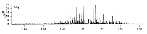
- FIG. 20 is an example of a light absorption spectrum of ammonia (NH 3 ), the horizontal axis of the graph indicates the wavelength, and the vertical axis indicates the light absorption intensity.
- Laser gas analyzers are known as gas analyzers that detect various gas concentrations using such light absorption spectra. This analyzer irradiates the measurement target gas with light emitted from a laser light source having the same emission wavelength region as the light absorption spectrum of the measurement target gas, and utilizes the absorption of laser light by the molecules and atoms of the measurement target gas. Concentration is measured.
- a gas analyzer using laser light measures the gas concentration based on the principle that the light absorption intensity at a specific wavelength is proportional to the gas concentration.
- the attenuation at the center wavelength ⁇ c of the absorption line is proportional to the gas concentration.
- lambda semiconductor laser beam is irradiated to a gas having an oscillation wavelength of c, it is possible to estimate the concentration of a gas by applying an appropriate coefficient to measure the attenuation.
- the concentration measurement method based on gas analysis using laser light includes a differential absorption method and a frequency modulation method.
- the gas concentration can be measured with a relatively simple configuration.
- the frequency modulation method signal processing is complicated, but highly sensitive gas concentration measurement is possible.
- Patent Document 1 Japanese Patent Laid-Open No. 7-151681, “Gas concentration measuring device”. As shown in FIG. 8 of Patent Document 1, this gas concentration measuring device is a device including a two-wavelength semiconductor laser, a gas cell, a light receiving lens, a light receiving unit, and a gas concentration measuring device.
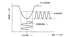
- a laser beam having an oscillation wavelength at the center wavelength ⁇ c of the absorption line As shown in the concentration measurement principle by the differential absorption method in FIG. 21, a laser beam having an oscillation wavelength at the center wavelength ⁇ c of the absorption line, a laser beam having an oscillation wavelength at the center wavelength ⁇ r without the absorption line, The gas is irradiated with the two types of laser light, and the signal intensity difference obtained by subtracting the intensity of the signal output from each light receiving unit is multiplied by an appropriate proportionality constant to be converted into a concentration.
- this gas concentration measuring device is a device including a frequency modulation type semiconductor laser, a gas cell, a light receiving lens, a light receiving unit, and a gas concentration measuring device.
- the center wavelength lambda c the output of the semiconductor laser is frequency-modulated at a modulation frequency f m, is irradiated to the measurement target gas of interest. Since the absorption line of the gas is almost quadratic function with respect to the frequency twice the frequency of the signal of the modulation frequency f m in the light receiving section this absorption line plays the role of a discriminator (second harmonic signal) can get. Then, it is possible to estimate the fundamental wave by amplitude modulation by performing envelope detection at the light receiving unit, and obtain a value proportional to the gas concentration by phase-synchronizing the ratio of the amplitude of the fundamental wave and the amplitude of the second harmonic wave. Is.
- a laser gas analyzer shown in FIG. 23 is known as a conventional gas analyzer using laser light.
- This laser type gas analyzer is described in Patent Document 2 (Japanese Patent Laid-Open No. 2009-47677, title of the invention “laser type gas analyzer”).
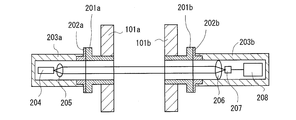
- reference numerals 101a and 101b denote flue walls through which the measurement target gas flows. On these flue walls 101a and 101b, the light emitting portion flange 201a and the light receiving portion flange 201b are arranged at positions facing each other.
- a light emitting unit casing 203a is attached to the light emitting unit flange 201a via a mounting bracket 202a.
- the light emitting unit housing 203a incorporates optical components such as a laser light source 204 and a collimating lens 205.
- a light receiving portion housing 203b is attached to the light receiving portion flange 201b via a mounting bracket 202b.
- the light receiving unit housing 203b includes a lens 206, a light receiving element 207, and a light receiving unit circuit board 208 that processes an output signal of the light receiving element 207.
- the laser light emitted from the laser light source 204 is applied to the inside of the flue, which is the measurement target space, and is received by the light receiving element 207 in the light receiving unit housing 203b disposed to face the laser light source 204.
- the light absorption circuit board 208 is utilized by utilizing the fact that this light absorption is related to the concentration of the measurement target gas.
- the above received light signal processing circuit calculates the gas concentration to be measured.
- Japanese Patent Laid-Open No. 7-151681 Invention Name “Gas Concentration Measuring Device”, paragraphs [0004], [0030], FIG. 7, FIG. 8, etc.
- Japanese Patent Laying-Open No. 2009-47677 Invention name “Laser Gas Analyzer”, paragraphs [0029] to [0038], FIGS. 1 to 7 etc.
- the above laser gas analyzer can be employed as a means for measuring the concentration of SO 2 gas or CO 2 gas.
- most conventional laser gas analyzers can measure one type of measurement target gas, and laser type gas analyzers capable of detecting two or more gas concentrations are CO + CO 2 , Gas species were limited, such as NH 3 + H 2 O, HCl + H 2 O, and the like.
- two laser gas analyzers have been required.
- SO 2 gas has a light absorption spectrum in the mid-infrared region.
- FIG. 24 shows a light absorption spectrum of SO 2.
- a quantum cascade laser that emits laser light having a wavelength in the mid-infrared region may be used as a laser light source. is assumed.
- CO 2 gas has a light absorption spectrum in the near infrared region.
- FIG. 25 shows a light absorption spectrum of CO 2.
- a semiconductor laser or the like that emits laser light having a wavelength in the near-infrared region may be used as a laser light source. is assumed.
- CO 2 gas having a spectrum as shown in FIG. 25 can include light having a wavelength that does not absorb CO 2 gas in a wavelength range that can be scanned by the near-infrared laser element to be used. Therefore, accurate gas concentration measurement is possible by correcting the amount of received light using the light having a wavelength that does not absorb the gas component to be measured using the prior art of Patent Document 2.
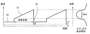
- the SO 2 gas having a spectrum as shown in FIG. 26 does not include light having a wavelength that does not absorb SO 2 gas in the wavelength range in which the mid-infrared laser element used can emit light. Therefore, DC absorption occurs due to the measurement target gas.
- Light amount decreasing by dust is DC, when measured in the mid-infrared light gases such as SO 2, either the absorption by the gas for measurement, to determine the amount of light attenuation due to dust, perform light amount correction There is a problem that it is difficult to perform accurate gas concentration measurement.
- FIG. 24 shows a light absorption spectrum of moisture, but there is a light absorption spectrum in the mid-infrared region as in the case of SO 2 gas, and it is possible to measure the SO 2 gas concentration by removing this light absorption spectrum. It is very difficult. That is, when the concentration of moisture in the measurement target space is high, the laser light emitted from the quantum cascade laser as the laser light source is affected by moisture other than the measurement target gas.
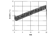
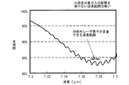
- FIG. 28 shows the level of the received light signal (in other words, the received light amount) when the light absorption spectrum wavelength of the SO 2 gas is detected as about 7.2 ⁇ m and the influence of absorption by moisture is experimentally examined.
- the attenuation of the amount of received light is only affected by dust, it can be corrected by the method described in Patent Document 2.
- the amount of received light attenuates as the water concentration (volume concentration) increases. I understand that.
- the conventional laser gas analyzer has a problem that the measurement value of the measurement target gas is attenuated when moisture exists in the measurement target space, and the gas concentration cannot be measured accurately.
- the problem to be solved by the present invention is that the gas concentration of the first measurement target gas in the mid-infrared region and the second measurement target in the near-infrared region even in a measurement environment where dust and high-concentration moisture exist.
- An object of the present invention is to provide a laser type gas analyzer capable of measuring the gas concentration of gas with high accuracy with a single device.
- a mid-infrared laser emitting section that emits laser light in the wavelength band of the mid-infrared region including the light absorption spectrum of the first measurement target gas;
- a mid-infrared laser driving section for driving the mid-infrared laser emitting section;
- a mid-infrared laser optical unit that collimates the laser light emitted from the mid-infrared laser emitting unit and irradiates the measurement target space where the first measurement target gas exists;
- a mid-infrared light receiving unit that receives the laser light emitted from the mid-infrared laser optical unit and outputs it as an electrical mid-infrared light reception signal;
- a mid-infrared light reception that extracts a signal component affected by light absorption by the first measurement target gas from the mid-infrared light reception signal and calculates a gas concentration of the first measurement target gas from a change amount of the signal component.
- a signal processing operation unit A first laser beam in the near-infrared wavelength band including the light absorption spectrum of the second measurement target gas, a second laser beam in the near-infrared wavelength band including the light absorption spectrum of moisture, and moisture
- a near-infrared laser light emitting unit that emits, by time, third laser light in a wavelength band of the near-infrared region in which light absorption spectra of the first measurement target gas and the second measurement target gas are equal to or less than a predetermined amount;
- a near infrared laser driving section for driving the near infrared laser emitting section;
- a near-infrared laser optical unit that collimates the first, second, and third laser beams emitted from the near-infrared laser light-emitting unit according to time and irradiates the measurement target space;
- a near-infrared light receiving unit that receives the first, second, and third laser beams emitted from the near-infrared laser optical unit according to time and output
- a near-infrared received light signal processing operation unit to perform The gas concentration of the first measurement target gas obtained by the mid-infrared light reception signal processing calculation unit and the near-infrared light reception signal are obtained using the water concentration and the light amount decrease obtained by the near-infrared light reception signal processing calculation unit.
- the invention according to claim 2 The laser gas analyzer according to claim 1, wherein The first measurement target gas is SO 2 gas, and the second measurement target gas is CO 2 gas.
- the invention according to claim 3 The laser gas analyzer according to claim 2, wherein
- the wavelength of the laser beam in the mid-infrared region emitted from the mid-infrared laser emission unit is 3 to 10 ⁇ m, and the wavelength of the laser beam in the near-infrared region emitted from the near-infrared laser emission unit is 0. It is 7 to 3 ⁇ m.
- the gas concentration of the first measurement target gas in the mid-infrared region and the second measurement target gas in the near-infrared region can be obtained even in a measurement environment where dust and high-concentration moisture exist. It is possible to provide a laser gas analyzer that can measure the gas concentration with high accuracy with a single device.
- FIG. 4A is a characteristic diagram showing the relationship between the light emission wavelength of the laser element and the current
- FIG. 4B is a characteristic diagram showing the relationship between the light emission wavelength of the laser element and temperature. is there.
- It is a figure which shows a wavelength scanning drive signal.
- It is a figure which shows the drive signal with respect to a laser element.
- It is a block diagram of a mid-infrared light reception signal processing calculation part and a near-infrared light reception signal processing calculation part.
- NH 3 ammonia
- FIG. It is a block diagram of the conventional laser type gas analyzer described in patent document 2.
- FIG. It is a diagram illustrating an optical absorption spectrum of sulfur dioxide (SO 2). It is a diagram showing a spectral characteristic of the CO 2 gas. Is a diagram showing spectral characteristics of SO 2 gas.
- FIG. 6 is a diagram showing a light absorption spectrum of water (H 2 O) in a wavelength region of 7.1 to 7.7 ⁇ m. It is a figure which shows the light reception signal level when there exists the influence of the absorption by water in a mid-infrared area
- the laser gas analyzer of the present embodiment as a specific example, a device for analyzing and SO 2 gas concentration and CO 2 gas concentration in the exhaust gas of the ship, the SO 2 gas as the first gas to be measured, also, The CO 2 gas was analyzed as the second measurement object gas.
- the laser gas analyzer eliminates the influence of moisture present in the measurement target space and the influence of dust present in the measurement target space in an environment where high concentrations of moisture and dust, such as ship exhaust gas, exist. those using infrared laser light emitting unit to measure the SO 2 gas concentration, and can measure the CO 2 gas concentration by using the near-infrared laser emitting portion, for measuring the gas concentration of interest with high precision It is.
- FIG. 1 shows an overall configuration of a laser type gas analyzer according to this embodiment.
- a light emitting portion flange 201a and a light receiving portion flange 201b are fixed to, for example, a flue wall 101a, 101b such as a flue through which the measurement target gas passes, by welding or the like.
- the light emitting unit casing 203a is attached to the light emitting unit flange 201a, and the light emitting unit case 3 is attached to the light unit housing 203a.
- a mid-infrared laser light emitting unit 7 that emits mid-infrared laser light
- a near-infrared laser light emitting unit 8 that emits near-infrared laser light
- a lens 9 that emits near-infrared laser light
- a concave mirror 10 are airtight.
- the window 18 that transmits light having a wavelength to be used airtightness inside the light emitting unit housing 203a is secured.
- a light emitting unit case 3 is attached to the light emitting unit casing 203a, and the light emitting unit circuit board 4 in the light emitting unit case 203a is provided with a mid-infrared laser driving unit 20 and a near unit as shown in detail in the block diagram of FIG.
- An infrared laser driving unit 21 is mounted. Electrical signals are sent from the mid-infrared laser driving unit 20 and the near-infrared laser driving unit 21 to the mid-infrared laser emitting unit 7 and the near-infrared laser emitting unit 8 so that the mid-infrared laser emitting unit 7
- the external light laser and the near-infrared laser light emitting unit 8 are configured to emit a near-infrared laser, respectively.
- the mid-infrared laser light emitting unit 7 emits a mid-infrared laser beam having a wavelength of 3 to 10 ⁇ m in the mid-infrared region including the light absorption spectrum of the SO 2 gas that is the first measurement target gas.
- the mid-infrared laser drive unit 20 generates a laser drive signal that sweeps the wavelength in the mid-infrared region and causes the mid-infrared laser emission unit 7 to emit light.
- the near-infrared laser emission unit 8 emits near-infrared laser light having a wavelength of 1.5 to 2.1 ⁇ m in the near-infrared region including the light absorption spectrum of the CO 2 gas that is the second measurement target gas.
- the near-infrared laser drive unit 21 is a laser element, and generates a laser drive signal that sweeps the wavelength in the near-infrared region to cause the near-infrared laser emission unit 8 to emit light.
- the emitted light from the mid-infrared laser light emitting unit 7 is collimated by the concave mirror 10 serving as the mid-infrared laser optical unit of the present invention to become parallel light, passes through the center of the light emitting unit flange 201a, and the mid-infrared laser light 2 As shown in FIG.
- This mid-infrared laser beam 2 is affected by light absorption by SO 2 gas, which is the first measurement target gas present in the flue interior 1.
- SO 2 gas which is the first measurement target gas present in the flue interior 1.
- it is affected by light scattering caused by dust present at the same time.
- moisture in the mid-infrared region is affected by moisture in the mid-infrared region.
- the light emitted from the near-infrared laser light-emitting unit 8 is converted into parallel light by the lens 9 and becomes the near-infrared laser light 17 from the opening 11 formed near the central portion of the concave mirror 10 to the light-emitting unit flange 201a. It irradiates the flue interior 1 through the center.
- the lens 9 and the opening part 11 comprise the near-infrared laser optical part of this invention.
- the near-infrared laser beam 17 is emitted coaxially inside the mid-infrared laser beam 2, and this near-infrared laser beam 17 is the second measurement object inside the flue 1. It is affected by light absorption by CO 2 gas which is a gas. In addition, it is affected by light scattering caused by dust present at the same time. In the near infrared region, there is a wavelength that is not affected by moisture, and this wavelength is used.
- a light receiving unit casing 203b is attached to the light receiving unit flange 201b.
- the mid-infrared laser beam 2 that has passed through the flue interior 1 is collected by the concave mirror 15 that is airtightly arranged inside the light receiving unit housing 203 b and received by the mid-infrared light receiving element 12. Further, by arranging the window 19 that transmits light of the wavelength to be used, airtightness inside the light emitting unit housing 203a is secured.
- the concave mirror 15 and the mid-infrared light receiving element 12 constitute a mid-infrared light receiving unit of the present invention.
- the mid-infrared light receiving element 12 is an MCT (Mercury Cadmium Tellurium) photoconductive element having sensitivity to wavelengths in the mid-infrared region, and the output signal of the mid-infrared light receiving element 12 is a light-receiving unit circuit in the light-receiving unit case 5 The signal is input to the mid-infrared received light signal processing calculation unit 22 (see FIG. 2) mounted on the substrate 6.
- MCT Manufacturing Cadmium Tellurium
- Mid-infrared light reception signal processing operation section 22 an infrared light receiving signal to the signal processing, gas concentration of the signal change component due to light absorption of SO 2 gas is extracted SO 2 gas in from mid-infrared light receiving element 12 This is obtained as a signal, and the gas concentration of SO 2 gas when the influence of moisture and light amount attenuation are not corrected is measured.
- the near-infrared laser beam 17 is condensed by the lens 14 through the opening 16 formed near the center of the concave mirror 15 and received by the near-infrared light receiving element 13.
- the opening part 16, the lens 14, and the near-infrared light receiving element 13 comprise the near-infrared light-receiving part in this invention.
- the near-infrared light receiving element 13 is an element such as a photodiode having sensitivity to wavelengths in the near-infrared region, and the output signal of the near-infrared light receiving element 13 is a near-infrared light-receiving signal processing operation of the light-receiving unit circuit board 6. It inputs into the part 23 (refer FIG. 2).
- the near-infrared light reception signal processing calculation unit 23 processes the signal of the near-infrared light receiving element 13 to collide with the gas concentration of CO 2 gas, moisture concentration, and dust when the light amount attenuation is not corrected. Measure the decrease in the amount of light due to scattering.
- the mid-infrared light reception signal processing calculation unit 22 and the near-infrared light reception signal processing calculation unit 23 are connected to the gas concentration correction unit 24, and correction is performed in consideration of the moisture concentration and the reduction in light quantity due to dust. Calculate the exact gas concentration.
- the mid-infrared laser drive unit 20 further includes a wavelength scanning drive signal generation unit 20a, a high frequency modulation signal generation unit 20b, a laser drive signal generation unit 20c, and a temperature control unit 20d.
- the mid-infrared laser light emitting section 7 further includes a mid-infrared laser element 7a, a temperature detection section (thermistor) 7b, and a temperature adjustment section (Peltier element) 7c.
- the mid-infrared laser element 7a can emit light at a wavelength whose emission wavelength matches the absorption characteristic of the first measurement target gas and its peripheral region, and further, as shown in FIG.
- the emission wavelength can be made variable, and the emission wavelength can be made variable depending on the temperature as shown in FIG.
- sulfur dioxide gas (SO 2 gas) is measured as the first measurement target gas, and a wavelength that absorbs sulfur dioxide gas (SO 2 gas) is also adopted as the wavelength.
- the temperature of the mid-infrared laser element 7a is detected using a temperature detector 7b such as a thermistor.
- This temperature detection unit 7 b is connected to the temperature control unit 20 d of the mid-infrared laser driving unit 20.
- the temperature control unit 20d performs PID control or the like so that the resistance value obtained from the temperature detection unit 7b such as a thermistor becomes constant in order to stabilize the emission wavelength of the mid-infrared laser element 7a and adjust the wavelength.
- the temperature of the temperature adjusting unit 7c such as a Peltier element is controlled to adjust the temperature of the mid-infrared laser element 7a.
- the output signal of the wavelength scanning driving signal generation unit 20a for changing the emission wavelength of the laser to scan the absorption wavelength of the SO 2 gas a sine wave, for example, about 10kHz to detect the absorption waveform of the SO 2 gas
- the drive signal generator 20c combines these output signals to generate a drive signal, and this drive The signal is VI converted and supplied to the mid-infrared laser element 7a.
- FIG. 5 shows an output signal of the wavelength scanning drive signal generator 20a.
- the wavelength scanning drive signal S 1 for scanning the absorption characteristic of the SO 2 gas changes the drive current value of the mid-infrared laser element 7a linearly and gradually changes the emission wavelength of the mid-infrared laser element 7a. Scan the light absorption characteristics of about 20 nm.
- the signal S 2 is the mid-infrared laser element 7a a drive current value is maintained above the threshold current to stabilize, is intended for illuminating at a certain wavelength. Furthermore, keep the signal S 3, the drive current value to 0 mA.
- a waveform diagram of a modulation signal output from the high-frequency modulation signal generation unit 20b is illustrated below the high-frequency modulation signal generation unit 20b in FIG. 3.
- This modulation signal is, for example, a sine wave having a frequency of 10 kHz.
- the wavelength width is about 0.2 nm.
- FIG. 6 is a waveform diagram of a drive signal output from the laser drive signal generation unit 20c of FIG. 3 (a combined signal of the output signal of the wavelength scanning drive signal generation unit 20a and the output signal of the high frequency modulation signal generation unit 20b).
- This drive signal has a trapezoidal shape that is repeated at a constant period.
- the laser drive signal generator 20c supplies this drive signal to the mid-infrared laser element 7a
- the mid-infrared laser element 7a can detect the light absorption characteristic of the measurement target gas at about 20 nm with a wavelength width of about 0.2 nm. Modulated light is output.
- a laser beam having a predetermined wavelength that is frequency-modulated for scanning the absorption characteristics of SO 2 gas is emitted from the mid-infrared laser element 7a.
- the laser light emitted from the mid-infrared laser element 7 a is emitted as parallel mid-infrared laser light 2 by the concave mirror 10.
- the temperature of the mid-infrared laser element 7a is adjusted in advance so that the SO 2 gas is measured at the center portion of the wavelength scanning drive signal.
- Such mid-infrared laser light 2 propagates inside the flue, which is an internal section of the flue walls 101a and 101b (a space in which the measurement target gas flows), and absorbs gas by SO 2 gas when passing through the flue wall. Receive.
- the operations and functions of the mid-infrared laser driving unit, mid-infrared laser light emitting unit, and mid-infrared laser optical unit of the present invention are as described above.
- the detection light that has propagated through the space where SO 2 gas, CO 2 gas, moisture and dust are present and received SO 2 gas is collected by the concave mirror 15 and then received by the mid-infrared light receiving element 12. Is done.
- the mid-infrared light receiving element 12 outputs a detection signal based on an electric signal according to the amount of received light.
- the mid-infrared light receiving element 12 is, for example, a photodiode, and an element having sensitivity to the emission wavelength of the laser is applied.
- the mid-infrared received light signal processing calculation unit 22 includes an I / V conversion unit 22a, a synchronous detection unit 22b, a reference signal generation unit (oscillator) 22c, a filter 22d, and a calculation unit 22e.
- the detection signal input from the mid-infrared light receiving element 12 to the gas concentration calculation unit 22 is converted from a current signal to a voltage signal by the I / V conversion unit 22a. This voltage signal has an output waveform as shown in FIG. This voltage signal is input to the synchronous detector 22b.
- the reference signal generator (oscillator) 22c outputs a signal having a frequency twice that of the high-frequency modulation signal from the high-frequency modulation signal generator 20b (see FIG. 3) as a reference signal to the synchronous detector 22b.
- the synchronous detection unit 22b extracts only the amplitude of the double frequency component of the modulation signal.
- the center wavelength lambda c, output are frequency modulation of the mid-infrared laser element 7a at the modulation frequency f m, the target SO
- the absorption line of the gas is almost quadratic function with respect to the frequency twice the frequency of the signal (second harmonic of the modulation frequency f m play the role of this absorption lines discriminator
- This signal gives a value proportional to the SO 2 gas concentration.
- This signal is input to the calculation unit 22e after the noise is removed by the filter unit 22d, and the concentration of SO 2 gas is calculated in the calculation unit 22e.
- concentration calculating the SO 2 gas by the frequency modulation When the light is absorbed by the SO 2 gas, a signal as shown in FIG. 11 is output to the calculation unit 22e through the filter unit 22d. Since this peak value becomes the gas concentration, the calculation unit 22e may measure the peak amplitude or integrate the signal change.
- the computing unit 22e can detect a gas concentration by multiplying the peak amplitude W span calibration value for SO 2 gas concentration with respect to A G A and gas temperature correction coefficient alpha A as shown in FIG. 11 .
- the gas temperature correction coefficient ⁇ A may be any coefficient that is uniquely determined with respect to the gas temperature of the SO 2 gas, and the format such as the function format or the table format is not limited.
- the calculation unit 22e sends the SO 2 gas concentration, which is affected by the influence of moisture and the decrease in the amount of light due to dust, to the gas concentration correction unit 24.
- the processing performed by the gas concentration correction unit 24 will be described later.
- the SO 2 gas concentration detection by mid-infrared light is performed in this way.
- the near-infrared laser driving unit 21 is driven to scan the first and second wavelength sweep bands as shown in FIG. First, scanning is performed to emit laser light (second laser light of the present invention) that measures the concentration of moisture as the first wavelength sweep band, and CO 2 gas is used as the second wavelength sweep band. Scanning for emitting a laser beam (a third laser beam according to the present invention) for measuring the amount of decrease in the amount of light following a laser beam (a first laser beam according to the present invention) for detecting the gas concentration of Done.
- the first and second wavelength sweep bands are continuously performed according to time. For example, the first wavelength sweep band is scanned for a predetermined period, and then the second wavelength sweep band is scanned for a predetermined period. Is.
- the near-infrared laser drive unit 21 scans the first wavelength sweep band (see FIG. 8), that is, a wavelength band in the near-infrared region that does not receive light absorption by CO 2 gas but includes a light absorption spectrum of moisture. A scan for emitting the second laser beam is performed.
- the light absorption spectrum of moisture is widely distributed in the mid-infrared region as shown in FIG.
- light absorption by SO 2 interferes with light absorption by moisture, making it difficult to accurately measure the SO 2 concentration.
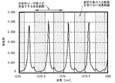
- FIG. 8 shows light absorption spectra of CO 2 and water near the wavelength of 1.99 ⁇ m.
- the light absorption spectrum of SO 2 gas does not exist in the near infrared region of 2 ⁇ m or less. Therefore, as the near infrared laser element 8 for measuring the gas concentration and moisture concentration of the CO 2 gas, for example, a semiconductor laser element that emits laser light having a wavelength of about 1.99 ⁇ m is selected. In the vicinity of the wavelength of 1.99 ⁇ m, the CO 2 gas and the absorption line of moisture are close to each other, but for example, moisture is measured in the first wavelength sweep region shown in FIG. CO 2 can be measured in the wavelength sweep region.
- the near-infrared laser driving unit 21 has the same configuration as the mid-infrared laser driving unit 20, and will be described with reference to FIG.
- the near-infrared laser drive unit 21 of the present invention includes a wavelength scanning drive signal generation unit 20a, a high-frequency modulation signal generation unit 20b, a laser drive signal generation unit 20c, and a temperature control unit 20d.
- the near-infrared laser emission unit 8 further includes a near-infrared laser element 8a, a temperature detection unit (thermistor) 7b, and a temperature adjustment unit (Peltier element) 7c.
- the near-infrared laser optical unit includes a lens 9 and an opening 11. Is provided.
- the near-infrared laser element 8a emits light at a wavelength whose emission wavelength matches the absorption characteristic of CO 2 gas and its peripheral region (including the absorption wavelength of moisture and the wavelength at which CO 2 gas and moisture hardly absorb).
- the emission wavelength can be made variable by the drive current, and the emission wavelength can be made variable by the temperature.
- the temperature of the near-infrared laser element 8a is detected using a temperature detector 7b such as a thermistor.
- This temperature detector 7 b is connected to the temperature controller 20 d of the near infrared laser driver 21.
- the temperature control unit 20d performs PID control or the like so that the resistance value obtained from the temperature detection unit 7b such as a thermistor becomes constant in order to stabilize the emission wavelength of the near-infrared laser element 8a and adjust the wavelength.
- the temperature of the temperature adjusting unit 7c such as a Peltier element is controlled to adjust the temperature of the near infrared laser element 8a.
- the near-infrared laser driving unit 21 does not receive light absorption by CO 2 gas, but emits a first laser beam having a wavelength in the near-infrared region that includes a light absorption spectrum of moisture. Scan the wavelength sweep band.
- the output wavelength of the wavelength scanning drive signal generator 20a that changes the emission wavelength of the laser so as to scan the first wavelength sweep band, and the emission wavelength with a sine wave of, for example, about 20 kHz for detecting the moisture absorption waveform
- the drive signal generator 20c synthesizes these output signals to generate a drive signal, and this drive signal is V ⁇ . I-converted and supplied to the near-infrared laser element 8a.
- the modulation of the near-infrared laser light is the same as the modulation of the mid-infrared laser, and the output signal of the wavelength scanning drive signal generator 20a in FIG. 13 is used.
- a waveform diagram of a modulation signal output from the high frequency modulation signal generation unit 20b is illustrated below the high frequency modulation signal generation unit 20b in FIG. 3.
- This modulation signal is, for example, a sine wave having a frequency of 20 kHz.
- the wavelength width is about 0.2 nm, and such an output signal is used.
- the laser drive signal generator 20c outputs the drive signal (the combined signal of the output signal of the wavelength scanning drive signal generator 20a and the output signal of the high frequency modulation signal generator 20b) output from the laser drive signal generator 20c.
- the near-infrared laser element 8a When this drive signal is supplied to the near-infrared laser element 8a, the near-infrared laser element 8a outputs modulated light capable of detecting the light absorption characteristics of water at about 20 nm with a wavelength width of about 0.2 nm.
- the near-infrared laser element 8a emits a laser beam having a predetermined wavelength that is frequency-modulated for scanning moisture absorption characteristics.
- the wavelength of this laser beam is set so as to scan the moisture absorption spectrum, as shown in FIG.
- the laser light emitted from the near infrared laser element 8 a passes through the central hole of the concave mirror 10 and is emitted as a parallel near infrared laser light 17.
- the temperature of the near-infrared laser element 8a is adjusted in advance so that moisture is measured at the central portion of the wavelength scanning drive signal.
- a laser beam having a wavelength in the near infrared region including the light absorption spectrum of moisture is emitted.
- Such near-infrared laser light 17 propagates through the interior of the flue, which is the internal section of the flue walls 101a and 101b (the space in which the measurement target gas flows), and receives gas absorption due to moisture when passing through the inside. .
- the detection light propagated through the space where SO 2 gas, CO 2 gas, moisture and dust are present is absorbed by laser light having a wavelength in the near infrared region including the light absorption spectrum of the moisture.
- the detection light passes through the opening 16 of the concave mirror 15 and is collected by the lens 14 and then received by the near-infrared light receiving element 13.
- the near-infrared light receiving element 13 outputs a detection signal based on an electrical signal according to the amount of received light.
- the near-infrared light receiving element 13 is, for example, a photodiode, and an element having sensitivity to the emission wavelength of the laser is applied.
- the near-infrared light reception signal processing calculation unit 23 has the same configuration as that of the mid-infrared light reception signal processing calculation unit 22, and as shown in FIG. 7, an I / V conversion unit 22a, a synchronous detection unit, and the like. 22b, an oscillator 22c, a filter 22d, and an arithmetic unit 22e.
- the detection signal input from the near-infrared light receiving element 13 to the near-infrared light reception signal processing calculation unit 23 is converted from a current signal to a voltage signal by the I / V conversion unit 22a.
- This voltage signal also has an output waveform as shown in FIG.
- This voltage signal is input to the synchronous detector 22b.
- the reference signal generator (oscillator) 22c outputs a signal having a frequency twice that of the high-frequency modulation signal generated by the high-frequency modulation signal generator 20b (see FIG. 3) to the synchronous detector 22b as a reference signal.
- the synchronous detection unit 22b extracts only the amplitude of the double frequency component of the modulation signal.
- This signal is input to the calculation unit 22e, and the concentration of moisture is calculated in the calculation unit 22e. And since this peak value becomes a density
- the computing unit 22e can detect a water concentration by multiplying the span calibration value G B and the temperature correction coefficient alpha B for water concentration in the amplitude W B of such peak value as shown in FIG. 11.
- the temperature correction coefficient ⁇ B may be a coefficient that is uniquely determined with respect to the moisture temperature, and the format such as the function format or the table format is not limited.
- the calculation unit 22e sends the moisture concentration to the gas concentration correction unit 24.
- the processing performed by the gas concentration correction unit 24 will be described later.
- the near-infrared laser driving unit 21 scans the second wavelength band, that is, the first laser light in the near-infrared wavelength band including the light absorption spectrum of the CO 2 gas, the moisture and the first
- the third laser beam in the near-infrared wavelength band that includes only a small amount of light absorption spectra of the measurement target gas (SO 2 gas) and the second measurement target gas (CO 2 gas), that is, a predetermined amount or less.
- a scan is performed to emit the light by time.
- the first laser beam is for detecting the concentration of CO 2 gas by utilizing light absorption by the CO 2 gas.
- the third laser beam has a light amount reduction amount due to dust using near infrared light. Used for calculation. The detection principle of the light amount reduction amount will be described first. When the laser beam is blocked by the influence of dust, the amount of received light decreases. When the amount of received light decreases, the amplitude of the detected gas absorption waveform also decreases, so that the gas concentration cannot be measured accurately.
- the received light quantity for calculating the correction coefficient is calculated in the near-infrared received light signal processing calculation unit 23.
- the gas concentration correction unit 24 accurate gas concentration detection is possible even in an environment where dust or the like is present.
- the near-infrared laser driver 21 scans the second wavelength band in order to continuously scan the absorption wavelength of CO 2 gas and scan for detecting the amount of light reduction.
- the modulation of the near-infrared laser light is the same as the modulation of the mid-infrared laser, and the output signal of the wavelength scanning drive signal generator 20a shown in FIG. 13B is used.
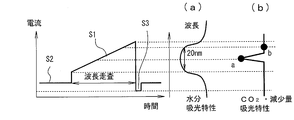
- the wavelength band is set so that CO 2 gas can be detected at the wavelength of point a and the amount of light reduction can be detected at the wavelength of point b. (The point a is the peak point of the white background region having the characteristic of FIG. 25, and the point b is the bottom point of the sandy region having the characteristic of FIG. 25.)
- the drive signal generator 20c In order to frequency-modulate the emission wavelength with the output signal of the wavelength scanning drive signal generator 20a that changes the emission wavelength of the laser adjusted in this way and a sine wave of, for example, about 20 kHz for detecting the absorption waveform of CO 2 gas.
- the drive signal generator 20c combines these output signals to generate a drive signal.
- the drive as shown in the waveform diagram of the drive signal (the combined signal of the output signal of the wavelength scanning drive signal generator 20a and the output signal of the high frequency modulation signal generator 20b) output from the laser drive signal generator 20c of FIG.
- the laser drive signal generator 20c converts the drive signal into VI and supplies it to the near-infrared laser element 8a.
- the near-infrared laser element 8a has a frequency-modulated predetermined wavelength band in which the light absorption characteristic of the second measurement object gas (CO 2 gas) is scanned with a wavelength width of about 0.2 nm. 1 laser beam is output, and a third laser beam in a predetermined wavelength band for obtaining a signal for detecting the amount of light reduction is emitted.
- the laser light emitted from the near infrared laser element 8 a passes through the central hole of the concave mirror 10 and is emitted as a parallel near infrared laser light 17.
- the temperature of the near-infrared laser element 8a is adjusted in advance so that gas is measured at the central portion of the wavelength scanning drive signal.
- a laser beam having a wavelength in the near infrared region including the light absorption spectrum of CO 2 gas and the wavelength for detecting the amount of light reduction is emitted.
- Such near-infrared laser light 17 propagates inside the flue, which is an internal section of the flue walls 101a and 101b (a space in which the measurement target gas flows), and absorbs gas by CO 2 gas when passing through the flue. Or receive a light reduction.
- the operations and functions of the near-infrared laser driving section, near-field laser emitting section, and near-infrared laser optical section of the present invention are as described above.
- the near-infrared light receiving unit of the present invention will be described.
- the first and third laser beams are output continuously, and signal processing is also performed continuously.
- the first laser beam is received first.
- the signal processing at this time will be described.
- the detection light propagated through the space in which SO 2 gas, CO 2 gas, moisture and dust are present is a laser beam having a wavelength in the near infrared region including the light absorption spectrum of CO 2 gas by the first laser light. Receives CO 2 gas absorption.
- the detection light passes through the opening 16 of the concave mirror 15 and is collected by the lens 14 and then received by the near-infrared light receiving element 13.
- the near-infrared light receiving element 13 outputs a detection signal based on an electrical signal according to the amount of received light.
- the near-infrared light receiving element 13 is, for example, a photodiode, and an element having sensitivity to the emission wavelength of the laser is applied.
- the detection signal input from the near-infrared light receiving element 13 to the near-infrared light reception signal processing calculation unit 23 Is converted from a current signal to a voltage signal by the I / V converter 22a.
- This voltage signal also has an output waveform as shown in FIG.
- This voltage signal is input to the synchronous detector 22b.
- the reference signal generator (oscillator) 22c outputs a signal having a frequency twice that of the high-frequency modulation signal generated by the high-frequency modulation signal generator 20b (see FIG. 3) to the synchronous detector 22b as a reference signal.
- the synchronous detection unit 22b extracts only the amplitude of the double frequency component of the modulation signal. This is measured by the principle of concentration measurement by the frequency modulation method shown in FIG.
- This signal is input to the arithmetic unit 22e after noise is removed by the filter unit 22d.
- the calculator 22e calculates the gas concentration of the CO 2 gas using this signal.
- This signal is a value proportional to the gas concentration of the CO 2 gas, and has a peak value as shown in FIG.
- the calculation unit 22e may measure the peak amplitude or integrate the signal change.
- computing unit 22e the gas concentration by multiplying the span calibration value G C and the gas temperature correction coefficient alpha C for CO 2 gas concentration in the amplitude W C, such synchronous detection signals shown in FIG. 11 Can be detected.
- the gas temperature correction coefficient ⁇ C may be a coefficient that is uniquely determined with respect to the gas temperature of the CO 2 gas, and the format such as the function format or the table format is not limited.
- the CO 2 gas concentration is less affected by moisture, but is affected by a decrease in the amount of light due to dust, and needs to be corrected.
- the calculation unit 22 e sends this CO 2 gas concentration to the gas concentration correction unit 24. The processing performed by the gas concentration correction unit 24 will be described later.
- the detection light propagated through the space where SO 2 gas, CO 2 gas, moisture and dust are present has a third wavelength band in the near infrared region not including the light absorption spectrum of CO 2 gas and SO 2 gas. Laser light does not absorb gas and only receives light quantity reduction due to dust.
- the detection light passes through the opening 16 of the concave mirror 15 and is collected by the lens 14 and then received by the near-infrared light receiving element 13.
- the near-infrared light receiving element 13 outputs a detection signal based on an electrical signal according to the amount of received light.
- the near-infrared light receiving element 13 is, for example, a photodiode, and an element having sensitivity to the emission wavelength of the laser is applied.
- the detection signal input from the near-infrared light receiving element 13 to the near-infrared light reception signal processing calculation unit 23 is converted into an I / V conversion of the near-infrared light reception signal processing calculation unit 23.
- the unit 22a converts the current signal into a voltage signal. This voltage signal has an output waveform as shown in FIG. This voltage signal is input to the synchronous detector 22b.
- the reference signal generator (oscillator) 22c outputs a signal having a frequency twice that of the high-frequency modulation signal from the high-frequency modulation signal generator 20b (see FIG. 3) as a reference signal to the synchronous detector 22b.
- the synchronous detection unit 22b extracts only the amplitude of the double frequency component of the modulation signal. This is measured by the principle of concentration measurement by the frequency modulation method shown in FIG.
- This signal is input to the arithmetic unit 22e after noise is removed by the filter unit 22d.
- This signal has a waveform as shown in FIG. 16, which is proportional to the decrease in the amount of light scattered by the dust, although it has not been absorbed by gas or moisture.
- the light amount reduction amount P at time 15 is calculated in the calculation unit 22e.
- the calculation unit 22 e sends the light amount reduction amount to the gas concentration correction unit 24. The processing performed by the gas concentration correction unit 24 will be described later.
- the gas concentration correction unit 24 uses the moisture concentration and the light amount decrease obtained by the near-infrared light reception signal processing calculation unit 23 to use the first measurement target gas (SO 2) obtained by the mid-infrared light reception signal processing calculation unit 22. Gas) and the gas concentration of the second measurement target gas (CO 2 gas) obtained by the near-infrared light reception signal processing calculation unit 23 are corrected. Specifically, the correction is performed by the moisture concentration and the light amount decrease amount for the gas concentration of the SO 2 gas, and the correction is performed by the light amount decrease amount for the gas concentration of the CO 2 gas.
- FIG. 17 shows changes in the amount of received light with respect to the dust amount of near infrared light and mid infrared light.
- the amount of received light greatly decreases as the amount of dust increases. From this value, the amount of light reduction is calculated by the following equation.
- the correlation between the near-infrared light quantity reduction amount and the mid-infrared light quantity reduction amount is taken, a graph as shown in FIG. 18 is obtained, and the characteristics of the near-infrared light and mid-infrared light quantity reduction against dust are strong. It can be seen that there is a correlation. Therefore, the amount of received mid-infrared light that is reduced by dust can be estimated based on the amount of received near-infrared light that is reduced by dust.
- FIG. 15 shows a case where there is no dust and the amount of received light is not reduced
- FIG. 16 is a case where there is dust and the amount of received light is reduced.
- the near infrared light at time 15 is not affected by the CO 2 gas unlike the point b in FIG. 13B, and therefore only a decrease due to the influence of dust is detected. be able to.
- the level P max of the received light signal when there is no dust and the received light amount is maximum is set in advance in the calculation unit 22e as the received light amount setting value.
- the calculation unit 22e detects the received light signal level Ps when dust is present as shown in FIG. 16 (when the light amount obtained by the third laser beam is reduced), and the light amount reduction amount is sent to the gas concentration correction unit 24. Output.
- the gas concentration correction unit 24 calculates the ratio of this Ps to P max at the same time as the received light quantity correction coefficient ⁇ by Equation 6.
- the gas concentration correction unit 24 can obtain a gas concentration in which the variation in the amount of received light caused by dust is corrected, as shown in Equation 7, by multiplying or dividing the received light amount correction coefficient ⁇ by the gas concentration. .
- the gas concentration correction unit 24 performs the above correction for each of the SO 2 gas concentration and the CO 2 gas concentration. Subsequently, based on the moisture concentration, the previously determined gas concentration measurement value of the SO 2 gas is corrected.
- this correction method it is possible to measure in advance how much the gas concentration measurement value decreases according to the moisture concentration in the measurement target space, so the known gas concentration measurement value decrease amount according to the light amount decrease amount due to the moisture concentration Is used to correct the measured gas concentration value of the SO 2 gas obtained previously.
- the amount of light reduction due to moisture concentration can be calculated by the same method as the amount of light reduction due to dust.
- ⁇ is a received light quantity correction coefficient due to moisture.
- the gas concentration correction unit 24 uses the moisture concentration output from the near-infrared light reception signal processing calculation unit 23, the gas concentration correction unit 24 calculates the received light amount correction coefficient ⁇ .
- the gas concentration correction unit 24 multiplies or divides the received light amount correction coefficient ⁇ by the SO 2 gas concentration (after correction) to correct the fluctuation amount of the received light amount due to moisture as shown in the following equation. Gas concentration can be obtained.
- the SO 2 gas concentration (see Equation 11) and the CO 2 gas concentration (see Equation 9) are sent to the output unit at the subsequent stage.
- the output unit is, for example, a display device or an alarm device, or a transmission device that transmits to another computer. Detection of the concentration of the measurement target gas by the frequency modulation method is performed in this way. By calculating the gas concentration in which the amount of decrease in light amount is corrected in this way, accurate gas concentration measurement of SO 2 and CO 2 can be performed even in an environment where the amount of received light varies due to dust.
- the second wavelength sweep band is set to be detected at the timing shown in FIG. 13B.
- CO 2 gas is detected at point c, and the amount of light reduction is detected at point b at the center of the wavelength, as shown in FIG. 19B
- CO 2 gas is detected at point e at the center of the wavelength
- Detecting the amount of light reduction at the points d and f on both sides of the CO 2 gas detecting CO 2 gas at the point h on one side of the wavelength as shown in FIG. 19C, and the point g on the other side of the wavelength
- the optimum wavelength corresponding to the first measurement target gas is selected from 3 to 10 ⁇ m in the mid-infrared region, and the wavelength of the laser light in the near-infrared region is also from 0.7 to 3 ⁇ m.
- An optimum wavelength corresponding to the second measurement target gas is selected.
- SO 2 gas is measured in the mid-infrared region and CO 2 gas is measured in the near-infrared region at the same time, and the distribution conditions of dust and moisture in the flue are the same in time. May be matched.
- FIG. 5 focusing on the point that a signal S 3 signal is output for each cycle as shown in Figure 6, from the detection of the S 3 signal Since the peak value of the synchronous detector output waveform appears when a predetermined time has elapsed, the concentration should be calculated at this timing. Although the concentration is measured, the presence or absence of the measurement target gas can be detected by determining that the measurement target gas does not exist when the concentration is almost zero.
- the optical paths of the mid-infrared light and the near-infrared light coincide with each other, but a configuration in which the optical paths are separated may be employed.
- the optical path for gas analysis and the optical path for measuring the decrease in the amount of light due to dust coincide.
- the near-infrared laser light 17 may be coaxially passed through the inside of the mid-infrared laser light 2.
- the mid-infrared laser light-emitting unit 7 and the near-infrared laser light-emitting unit 8 are used. May be reversed so that the mid-infrared laser beam 2 passes coaxially through the inside of the near-infrared laser beam 17.
- the present invention is not limited to the above-described embodiment other than the arrangement of the laser light emitting units 7 and 8, and includes many changes without departing from the essence thereof.
- each of them is described as emitting and detecting in synchronization with each other, but a CPU unit (not shown) is replaced with a mid-infrared laser driving unit 20, a near-infrared laser driving unit 21, a mid-infrared received light signal processing calculation unit. 22, it may be connected to the near-infrared light reception signal processing calculation unit 23 and the gas concentration correction unit 24, and the CPU unit may perform operation control and calculation for light emission and detection while adjusting the timing.
- the amount of decrease can be measured under the same conditions, and the concentration of SO 2 gas having an absorption spectrum over the entire laser light wavelength scanning range can be accurately measured, and CO 2 gas can be simultaneously measured.
- the measured gas concentration can be corrected by measuring the moisture concentration using the near-infrared laser beam 17, so that the measurement The concentration of the target gas can be measured with high accuracy.
- the laser gas analyzer of the present invention is optimal for measuring combustion exhaust gas such as boilers and garbage incineration.
- gas analysis for steel blast furnace, converter, heat treatment furnace, sintering (pellet equipment), coke oven], fruit and vegetable storage and ripening, biochemistry (microorganism) [fermentation], air pollution [incinerator, flue gas desulfurization / Denitration], automobile exhaust gas (remove tester), disaster prevention [explosive gas detection, toxic gas detection, new building material combustion gas analysis], plant growth, chemical analysis [oil refinery plant, petrochemical plant, gas generation plant], It is also useful as an analyzer for environmental [landing concentration, tunnel concentration, parking lot, building management], and various physics and chemistry experiments.
Abstract
Provided is a laser-type gas analyzer capable of measuring, with a high degree of precision using one device, the gas concentration of a first gas to be measured in a mid-infrared range and the gas concentration of a second gas to be measured in a near-infrared range, even in a measurement environment where dust and a high concentration of water are present.
A laser-type gas analyzer comprises: a processing and calculating unit for received mid-infrared light signals (22) that calculates, from a received mid-infrared light signal, the gas concentration of a first gas to be measured; a processing and calculating unit for received near-infrared light signals (23) that detects by time, from a received near-infrared light signal, the gas concentration of a second gas to be measured, water concentration in the air, and amount of light reduction due to dust; and a gas concentration correcting unit (24) that corrects the gas concentrations for each of the first and the second gases to be measured using the water concentration and amount of light reduction.
Description
本発明は、煙道内の各種ガスのガス濃度をレーザ光により測定するレーザ式ガス分析計に関するものである。
The present invention relates to a laser gas analyzer that measures the gas concentration of various gases in a flue with a laser beam.
ガスの分子・原子には、それぞれ固有の光吸収スペクトルがあることが知られている。例えば、図20はアンモニア(NH3)の光吸収スペクトルの例であり、グラフの横軸は波長を示し、縦軸は光吸収強度を示している。
このような光吸収スペクトルを利用して各種ガス濃度を検出するガス分析計として、レーザ式ガス分析計が知られている。この分析計は、測定対象ガスの光吸収スペクトルと同じ発光波長領域を有するレーザ光源からの出射光を測定対象ガスに照射し、測定対象ガスの分子・原子によるレーザ光の吸収を利用してガス濃度を計測するものである。 It is known that each gas molecule / atom has its own light absorption spectrum. For example, FIG. 20 is an example of a light absorption spectrum of ammonia (NH 3 ), the horizontal axis of the graph indicates the wavelength, and the vertical axis indicates the light absorption intensity.
Laser gas analyzers are known as gas analyzers that detect various gas concentrations using such light absorption spectra. This analyzer irradiates the measurement target gas with light emitted from a laser light source having the same emission wavelength region as the light absorption spectrum of the measurement target gas, and utilizes the absorption of laser light by the molecules and atoms of the measurement target gas. Concentration is measured.
レーザ光を用いたガス分析計は、特定波長の光吸収強度がガスの濃度に比例する原理に基づいて、ガス濃度を測定する。吸収線の中心波長λcにおける減衰量は、ガスの濃度に比例する。したがって、λcの発振波長をもつ半導体レーザ光をガスに照射し、その減衰量を測定し適当な係数を掛けることでガスの濃度を推定することができる。
A gas analyzer using laser light measures the gas concentration based on the principle that the light absorption intensity at a specific wavelength is proportional to the gas concentration. The attenuation at the center wavelength λ c of the absorption line is proportional to the gas concentration. Thus, lambda semiconductor laser beam is irradiated to a gas having an oscillation wavelength of c, it is possible to estimate the concentration of a gas by applying an appropriate coefficient to measure the attenuation.
このようにレーザ光を用いたガス分析による濃度計測方法は、大きく差分吸収方式と周波数変調方式がある。通常、差分吸収方式では、比較的簡単な構成でガス濃度の測定が可能である。一方、周波数変調方式では、信号処理が複雑になるが高感度なガス濃度測定が可能である。
As described above, the concentration measurement method based on gas analysis using laser light includes a differential absorption method and a frequency modulation method. Usually, in the differential absorption method, the gas concentration can be measured with a relatively simple configuration. On the other hand, with the frequency modulation method, signal processing is complicated, but highly sensitive gas concentration measurement is possible.
差分吸収方式によりガス濃度を測定する装置は、例えば特許文献1(特開平7-151681号公報、発明の名称「ガス濃度測定装置」)に記載されている。このガス濃度測定装置は、特許文献1の図8で示すように、2波長式半導体レーザ、ガスセル、受光レンズ、受光部、ガス濃度測定装置を備えた装置である。
An apparatus for measuring the gas concentration by the differential absorption method is described in, for example, Patent Document 1 (Japanese Patent Laid-Open No. 7-151681, “Gas concentration measuring device”). As shown in FIG. 8 of Patent Document 1, this gas concentration measuring device is a device including a two-wavelength semiconductor laser, a gas cell, a light receiving lens, a light receiving unit, and a gas concentration measuring device.
そして、図21の差分吸収方式による濃度測定原理でも示すように、吸収線の中心波長λcを発振波長とするレーザ光と、吸収線の無い中心波長λrを発振波長とするレーザ光と、という2種のレーザ光をガスに照射し、それぞれの受光部が出力する信号の強度を差分して得た信号強度差に適当な比例定数を掛けて濃度に換算する、というものである。
As shown in the concentration measurement principle by the differential absorption method in FIG. 21, a laser beam having an oscillation wavelength at the center wavelength λ c of the absorption line, a laser beam having an oscillation wavelength at the center wavelength λ r without the absorption line, The gas is irradiated with the two types of laser light, and the signal intensity difference obtained by subtracting the intensity of the signal output from each light receiving unit is multiplied by an appropriate proportionality constant to be converted into a concentration.
また、周波数変調方式によりガス濃度を測定する装置も、例えば先に述べた特許文献1に記載されている。このガス濃度測定装置は、特許文献1の図7で示すように、周波数変調式半導体レーザ、ガスセル、受光レンズ、受光部、ガス濃度測定装置を備えた装置である。
An apparatus for measuring the gas concentration by the frequency modulation method is also described in, for example, Patent Document 1 described above. As shown in FIG. 7 of Patent Document 1, this gas concentration measuring device is a device including a frequency modulation type semiconductor laser, a gas cell, a light receiving lens, a light receiving unit, and a gas concentration measuring device.
そして、図22の周波数変調方式による濃度測定原理で示すように、中心波長λc、変調周波数fmで半導体レーザの出力を周波数変調し、対象となる測定対象ガスに照射する。ガスの吸収線は周波数に対してほぼ2次関数となっているので、この吸収線が弁別器の役割を果たし受光部では変調周波数fmの2倍の周波数の信号(2倍波信号)が得られる。そして、受光部でエンベロープ検波を行うことで振幅変調による基本波を推定でき、この基本波の振幅と前記2倍波の振幅の比を位相同期させることでガス濃度に比例した値を得る、というものである。
Then, as shown in concentrations measuring principle according to the frequency modulation scheme of Figure 22, the center wavelength lambda c, the output of the semiconductor laser is frequency-modulated at a modulation frequency f m, is irradiated to the measurement target gas of interest. Since the absorption line of the gas is almost quadratic function with respect to the frequency twice the frequency of the signal of the modulation frequency f m in the light receiving section this absorption line plays the role of a discriminator (second harmonic signal) can get. Then, it is possible to estimate the fundamental wave by amplitude modulation by performing envelope detection at the light receiving unit, and obtain a value proportional to the gas concentration by phase-synchronizing the ratio of the amplitude of the fundamental wave and the amplitude of the second harmonic wave. Is.
そして、レーザ光を用いたガス分析計の従来技術としては、例えば、図23に示すレーザ式ガス分析計が知られている。なお、このレーザ式ガス分析計は、特許文献2(特開2009-47677号公報、発明の名称「レーザ式ガス分析計」)に記載されているものである。
For example, a laser gas analyzer shown in FIG. 23 is known as a conventional gas analyzer using laser light. This laser type gas analyzer is described in Patent Document 2 (Japanese Patent Laid-Open No. 2009-47677, title of the invention “laser type gas analyzer”).
図23において、101a,101bは測定対象ガスが流れる煙道壁である。これらの煙道壁101a,101bには、発光部フランジ201a、受光部フランジ201bが対向した位置にそれぞれ配置されている。
23, reference numerals 101a and 101b denote flue walls through which the measurement target gas flows. On these flue walls 101a and 101b, the light emitting portion flange 201a and the light receiving portion flange 201b are arranged at positions facing each other.
発光部フランジ201aには、取付金具202aを介して発光部筐体203aが取り付けられている。この発光部筐体203aには、レーザ光源204とコリメートレンズ205等の光学部品が内蔵されている。受光部フランジ201bには、取付金具202bを介して受光部筺体203bが取り付けられている。この受光部筺体203bには、レンズ206、受光素子207、および、受光素子207の出力信号を処理する受光部回路基板208が内蔵されている。
A light emitting unit casing 203a is attached to the light emitting unit flange 201a via a mounting bracket 202a. The light emitting unit housing 203a incorporates optical components such as a laser light source 204 and a collimating lens 205. A light receiving portion housing 203b is attached to the light receiving portion flange 201b via a mounting bracket 202b. The light receiving unit housing 203b includes a lens 206, a light receiving element 207, and a light receiving unit circuit board 208 that processes an output signal of the light receiving element 207.
上記構成において、レーザ光源204から出射されたレーザ光は測定対象空間である煙道内部に照射され、レーザ光源204に対向して配置された受光部筐体203b内の受光素子207により受光される。
この受光により、煙道内部に測定対象ガスが存在する場合にはレーザ光が吸収されるので、この光吸収が測定対象ガスの濃度と関連性を有することを利用して、受光部回路基板208上の受光信号処理回路が測定対象ガス濃度を演算するものである。 In the above configuration, the laser light emitted from thelaser light source 204 is applied to the inside of the flue, which is the measurement target space, and is received by the light receiving element 207 in the light receiving unit housing 203b disposed to face the laser light source 204. .
When the measurement target gas is present inside the flue due to this light reception, the laser light is absorbed. Therefore, the lightabsorption circuit board 208 is utilized by utilizing the fact that this light absorption is related to the concentration of the measurement target gas. The above received light signal processing circuit calculates the gas concentration to be measured.
この受光により、煙道内部に測定対象ガスが存在する場合にはレーザ光が吸収されるので、この光吸収が測定対象ガスの濃度と関連性を有することを利用して、受光部回路基板208上の受光信号処理回路が測定対象ガス濃度を演算するものである。 In the above configuration, the laser light emitted from the
When the measurement target gas is present inside the flue due to this light reception, the laser light is absorbed. Therefore, the light
近年、船舶の排ガスに対する規制が強化されている。具体的には、SOxの規制があり、排ガスのSO2ガスとCO2ガスとの濃度を測定し、以下の数1の基準を満たすことが求められている。
In recent years, regulations on ship exhaust gas have been strengthened. Specifically, there is a restriction on SOx, and it is required to measure the concentrations of SO 2 gas and CO 2 gas in the exhaust gas and satisfy the following equation (1).
[数1]
SO2ガス濃度(ppm)÷CO2ガス濃度(vol%)<4.3 [Equation 1]
SO 2 gas concentration (ppm) ÷ CO 2 gas concentration (vol%) <4.3
SO2ガス濃度(ppm)÷CO2ガス濃度(vol%)<4.3 [Equation 1]
SO 2 gas concentration (ppm) ÷ CO 2 gas concentration (vol%) <4.3
SO2ガスやCO2ガスの濃度を測定する手段として、上記のようなレーザ式ガス分析計を採用することができる。しかしながら、従来のほとんどのレーザ式ガス分析計は、測定が可能な測定対象ガスの種類は1台あたり1種類であり、2種類以上のガス濃度を検出できるレーザ式ガス分析計は、CO+CO2、NH3+H2O、HCl+H2Oなどのように、ガス種が限定されていた。船舶排ガスのようにSO2ガスとCO2ガスの濃度を測定する場合は、従来では2台のレーザ式ガス分析計が必要になっていた。
As a means for measuring the concentration of SO 2 gas or CO 2 gas, the above laser gas analyzer can be employed. However, most conventional laser gas analyzers can measure one type of measurement target gas, and laser type gas analyzers capable of detecting two or more gas concentrations are CO + CO 2 , Gas species were limited, such as NH 3 + H 2 O, HCl + H 2 O, and the like. In the case of measuring the concentration of SO 2 gas and CO 2 gas like ship exhaust gas, conventionally, two laser gas analyzers have been required.
この理由について説明する。
SO2ガスは、中赤外領域に光吸収スペクトルが存在する。例えば、図24はSO2の光吸収スペクトルであり、このような光吸収スペクトルを検出するためには、レーザ光源として中赤外領域の波長のレーザ光を出射する量子カスケードレーザ等を用いることが想定される。 The reason for this will be described.
SO 2 gas has a light absorption spectrum in the mid-infrared region. For example, FIG. 24 shows a light absorption spectrum of SO 2. In order to detect such a light absorption spectrum, a quantum cascade laser that emits laser light having a wavelength in the mid-infrared region may be used as a laser light source. is assumed.
また、CO2ガスは近赤外領域に光吸収スペクトルが存在する。例えば、図25はCO2の光吸収スペクトルであり、このような光吸収スペクトルを検出するためには、レーザ光源として、近赤外領域の波長のレーザ光を出射する半導体レーザ等を用いることが想定される。
Further, CO 2 gas has a light absorption spectrum in the near infrared region. For example, FIG. 25 shows a light absorption spectrum of CO 2. In order to detect such a light absorption spectrum, a semiconductor laser or the like that emits laser light having a wavelength in the near-infrared region may be used as a laser light source. is assumed.
このようにレーザ光源が異なる2台のレーザ式ガス分析計が必要となる。従って、分析計のコストや施工コストが上昇してしまう。さらには装置の大型化も問題となる。一台でSO2ガスやCO2ガスの濃度を共に測定するコンパクトなレーザ式ガス分析計が必要であった。
Thus, two laser gas analyzers with different laser light sources are required. Therefore, the analyzer cost and construction cost increase. Furthermore, the enlargement of the apparatus becomes a problem. A compact laser type gas analyzer that measures both the concentration of SO 2 gas and CO 2 gas with a single unit was required.
また、船舶の排ガス中には、水分や煤塵(ダスト)が存在する。ダストによる光量減衰の影響は特許文献2に記載された従来技術によって補正することが可能であり、仮に煙道内にダストが存在しても、ガス濃度を正確に測定することができる。
Also, moisture and dust are present in the exhaust gas of the ship. The influence of attenuation of light quantity due to dust can be corrected by the conventional technique described in Patent Document 2. Even if dust exists in the flue, the gas concentration can be accurately measured.
例えば、図25に示すようなスペクトルをもつCO2ガスは、使用する近赤外レーザ素子が走査できる波長範囲に、CO2ガスの吸収を受けない波長の光を含めることが可能である。そのため、特許文献2の従来技術を用いて、測定対象ガス成分の吸収を受けない波長の光を利用して受光光量補正を行うことで正確なガス濃度測定が可能である。
For example, CO 2 gas having a spectrum as shown in FIG. 25 can include light having a wavelength that does not absorb CO 2 gas in a wavelength range that can be scanned by the near-infrared laser element to be used. Therefore, accurate gas concentration measurement is possible by correcting the amount of received light using the light having a wavelength that does not absorb the gas component to be measured using the prior art of Patent Document 2.
ところが、図26に示すようなスペクトルをもつSO2ガスは、使用する中赤外レーザ素子の発光可能な波長範囲にSO2ガスの吸収を受けないような波長の光が含まれていない。そのため、測定対象ガスによってDC的な吸収が発生する。ダストによる光量減少はDC的であり、SO2のようなガスを中赤外光で測定する場合は、測定対象ガスによる吸収なのか、ダストによる光量減衰なのかを判別し、受光光量補正を行い正確なガス濃度測定を行うことが困難であるという問題があった。
However, the SO 2 gas having a spectrum as shown in FIG. 26 does not include light having a wavelength that does not absorb SO 2 gas in the wavelength range in which the mid-infrared laser element used can emit light. Therefore, DC absorption occurs due to the measurement target gas. Light amount decreasing by dust is DC, when measured in the mid-infrared light gases such as SO 2, either the absorption by the gas for measurement, to determine the amount of light attenuation due to dust, perform light amount correction There is a problem that it is difficult to perform accurate gas concentration measurement.
そして、排ガス中に水分が多く存在する場合はさらに問題がある。SO2ガスを測定するための中赤外領域(図24)には、測定対象ガスであるSO2ガスの光吸収スペクトル以外に、水分の光吸収スペクトルが多数存在している。図27は水分の光吸収スペクトルを示しているが、SO2ガスと同様に中赤外領域に光吸収スペクトルが存在しており、この光吸収スペクトルを外してSO2ガス濃度を測定することは非常に困難である。
すなわち、測定対象空間の水分の濃度が高い場合、レーザ光源としての量子カスケードレーザから出射されるレーザ光は測定対象ガス以外に水分の影響を受ける。 And when there is much water in the exhaust gas, there is a further problem. The mid-infrared region for measuring the SO 2 gas (FIG. 24), in addition to the light absorption spectrum of the SO 2 gas which is a measurement target gas, the optical absorption spectrum of water are present a number. FIG. 27 shows a light absorption spectrum of moisture, but there is a light absorption spectrum in the mid-infrared region as in the case of SO 2 gas, and it is possible to measure the SO 2 gas concentration by removing this light absorption spectrum. It is very difficult.
That is, when the concentration of moisture in the measurement target space is high, the laser light emitted from the quantum cascade laser as the laser light source is affected by moisture other than the measurement target gas.
この影響により受光光量が減衰するという問題がある。この点について説明する。ここにSO2ガスの光吸収スペクトル波長を約7.2μmとして検出するものとし、水分による吸収の影響を実験的に調べた場合の受光信号(言い換えれば受光光量)のレベルを図28に示す。
There is a problem that the amount of received light is attenuated by this influence. This point will be described. FIG. 28 shows the level of the received light signal (in other words, the received light amount) when the light absorption spectrum wavelength of the SO 2 gas is detected as about 7.2 μm and the influence of absorption by moisture is experimentally examined.
受光光量の減衰がダストによる影響だけであれば、特許文献2に記載された方法により補正が可能であるが、図28によれば、水分濃度(体積濃度)が高くなるにつれて受光光量が減衰することがわかる。このため、従来のレーザ式ガス分析計では、測定対象空間に水分が存在すると測定対象ガスの測定値が減衰してしまい、ガス濃度を正確に測定できないという問題があった。
このように船舶の排ガス中のSO2ガス濃度とCO2ガス濃度とを分析するためにはダストによる影響や、水分による影響を、ともに除去する必要があった。 If the attenuation of the amount of received light is only affected by dust, it can be corrected by the method described inPatent Document 2. However, according to FIG. 28, the amount of received light attenuates as the water concentration (volume concentration) increases. I understand that. For this reason, the conventional laser gas analyzer has a problem that the measurement value of the measurement target gas is attenuated when moisture exists in the measurement target space, and the gas concentration cannot be measured accurately.
Thus, in order to analyze the SO 2 gas concentration and the CO 2 gas concentration in the exhaust gas of the ship, it is necessary to remove both the influence due to dust and the influence due to moisture.
このように船舶の排ガス中のSO2ガス濃度とCO2ガス濃度とを分析するためにはダストによる影響や、水分による影響を、ともに除去する必要があった。 If the attenuation of the amount of received light is only affected by dust, it can be corrected by the method described in
Thus, in order to analyze the SO 2 gas concentration and the CO 2 gas concentration in the exhaust gas of the ship, it is necessary to remove both the influence due to dust and the influence due to moisture.
そして、SO2ガスのように中赤外領域の第1の測定対象ガスのガス濃度と、CO2ガスのように近赤外領域の第2の測定対象ガスのガス濃度と、を測定する場合には同様の問題が生じるため、ダストによる影響や、水分による影響を除去する必要があった。
When measuring the gas concentration of the first measurement target gas in the mid-infrared region like SO 2 gas and the gas concentration of the second measurement target gas in the near-infrared region like CO 2 gas Since the same problem occurs in the case, it was necessary to remove the influence of dust and the influence of moisture.
そこで本発明の解決課題は、ダストおよび高濃度の水分が存在する測定環境であっても、中赤外領域の第1の測定対象ガスのガス濃度と、近赤外領域の第2の測定対象ガスのガス濃度と、を1台の装置で高精度に測定可能としたレーザ式ガス分析計を提供することにある。
Therefore, the problem to be solved by the present invention is that the gas concentration of the first measurement target gas in the mid-infrared region and the second measurement target in the near-infrared region even in a measurement environment where dust and high-concentration moisture exist. An object of the present invention is to provide a laser type gas analyzer capable of measuring the gas concentration of gas with high accuracy with a single device.
上記課題を解決するため、請求項1に係る発明は、
第1の測定対象ガスの光吸収スペクトルを含む中赤外領域の波長帯域のレーザ光を出射する中赤外レーザ発光部と、
前記中赤外レーザ発光部を駆動する中赤外レーザ駆動部と、
前記中赤外レーザ発光部から出射されたレーザ光をコリメートして第1の測定対象ガスが存在する測定対象空間に照射する中赤外レーザ光学部と、
前記中赤外レーザ光学部から照射されたレーザ光を受光して電気的な中赤外受光信号として出力する中赤外受光部と、
前記中赤外受光信号から第1の測定対象ガスによる光吸収の影響を受けた信号成分を抽出してこの信号成分の変化量から第1の測定対象ガスのガス濃度を演算する中赤外受光信号処理演算部と、
第2の測定対象ガスの光吸収スペクトルを含む近赤外領域の波長帯域の第1のレーザ光、水分の光吸収スペクトルを含む近赤外領域の波長帯域の第2のレーザ光、および、水分と第1の測定対象ガスと第2の測定対象ガスの光吸収スペクトルが所定量以下である近赤外領域の波長帯域の第3のレーザ光を時間別に出射する近赤外レーザ発光部と、
前記近赤外レーザ発光部を駆動する近赤外レーザ駆動部と、
前記近赤外レーザ発光部から出射された第1,第2,第3のレーザ光を時間別にコリメートして測定対象空間に照射する近赤外レーザ光学部と、
前記近赤外レーザ光学部から照射された第1,第2,第3のレーザ光を時間別に受光して電気的な近赤外受光信号として出力する近赤外受光部と、
第1のレーザ光の近赤外受光信号から第2の測定対象ガスによる光吸収の影響を受けた信号成分を抽出してこの信号成分の変化量から第2の測定対象ガスのガス濃度を演算し、第2のレーザ光の近赤外受光信号から前記空間の水分濃度を演算し、また、第3のレーザ光の近赤外受光信号からダストによる光量減少量を演算するという処理を時間別に行う近赤外受光信号処理演算部と、
前記近赤外受光信号処理演算部により求めた水分濃度および光量減少量を用いて、前記中赤外受光信号処理演算部により求めた第1の測定対象ガスのガス濃度および前記近赤外受光信号処理演算部により求めた第2の測定対象ガスのガス濃度を、それぞれ補正するガス濃度補正部と、
を備えたことを特徴とする。 In order to solve the above problem, the invention according toclaim 1
A mid-infrared laser emitting section that emits laser light in the wavelength band of the mid-infrared region including the light absorption spectrum of the first measurement target gas;
A mid-infrared laser driving section for driving the mid-infrared laser emitting section;
A mid-infrared laser optical unit that collimates the laser light emitted from the mid-infrared laser emitting unit and irradiates the measurement target space where the first measurement target gas exists;
A mid-infrared light receiving unit that receives the laser light emitted from the mid-infrared laser optical unit and outputs it as an electrical mid-infrared light reception signal;
A mid-infrared light reception that extracts a signal component affected by light absorption by the first measurement target gas from the mid-infrared light reception signal and calculates a gas concentration of the first measurement target gas from a change amount of the signal component. A signal processing operation unit;
A first laser beam in the near-infrared wavelength band including the light absorption spectrum of the second measurement target gas, a second laser beam in the near-infrared wavelength band including the light absorption spectrum of moisture, and moisture A near-infrared laser light emitting unit that emits, by time, third laser light in a wavelength band of the near-infrared region in which light absorption spectra of the first measurement target gas and the second measurement target gas are equal to or less than a predetermined amount;
A near infrared laser driving section for driving the near infrared laser emitting section;
A near-infrared laser optical unit that collimates the first, second, and third laser beams emitted from the near-infrared laser light-emitting unit according to time and irradiates the measurement target space;
A near-infrared light receiving unit that receives the first, second, and third laser beams emitted from the near-infrared laser optical unit according to time and outputs an electrical near-infrared light reception signal;
The signal component affected by the light absorption by the second measurement target gas is extracted from the near-infrared light reception signal of the first laser light, and the gas concentration of the second measurement target gas is calculated from the change amount of the signal component. Then, the process of calculating the moisture concentration in the space from the near-infrared light reception signal of the second laser light and calculating the amount of light reduction due to dust from the near-infrared light reception signal of the third laser light is performed according to time. A near-infrared received light signal processing operation unit to perform,
The gas concentration of the first measurement target gas obtained by the mid-infrared light reception signal processing calculation unit and the near-infrared light reception signal are obtained using the water concentration and the light amount decrease obtained by the near-infrared light reception signal processing calculation unit. A gas concentration correction unit for correcting the gas concentration of the second measurement target gas obtained by the processing calculation unit, and
It is provided with.
第1の測定対象ガスの光吸収スペクトルを含む中赤外領域の波長帯域のレーザ光を出射する中赤外レーザ発光部と、
前記中赤外レーザ発光部を駆動する中赤外レーザ駆動部と、
前記中赤外レーザ発光部から出射されたレーザ光をコリメートして第1の測定対象ガスが存在する測定対象空間に照射する中赤外レーザ光学部と、
前記中赤外レーザ光学部から照射されたレーザ光を受光して電気的な中赤外受光信号として出力する中赤外受光部と、
前記中赤外受光信号から第1の測定対象ガスによる光吸収の影響を受けた信号成分を抽出してこの信号成分の変化量から第1の測定対象ガスのガス濃度を演算する中赤外受光信号処理演算部と、
第2の測定対象ガスの光吸収スペクトルを含む近赤外領域の波長帯域の第1のレーザ光、水分の光吸収スペクトルを含む近赤外領域の波長帯域の第2のレーザ光、および、水分と第1の測定対象ガスと第2の測定対象ガスの光吸収スペクトルが所定量以下である近赤外領域の波長帯域の第3のレーザ光を時間別に出射する近赤外レーザ発光部と、
前記近赤外レーザ発光部を駆動する近赤外レーザ駆動部と、
前記近赤外レーザ発光部から出射された第1,第2,第3のレーザ光を時間別にコリメートして測定対象空間に照射する近赤外レーザ光学部と、
前記近赤外レーザ光学部から照射された第1,第2,第3のレーザ光を時間別に受光して電気的な近赤外受光信号として出力する近赤外受光部と、
第1のレーザ光の近赤外受光信号から第2の測定対象ガスによる光吸収の影響を受けた信号成分を抽出してこの信号成分の変化量から第2の測定対象ガスのガス濃度を演算し、第2のレーザ光の近赤外受光信号から前記空間の水分濃度を演算し、また、第3のレーザ光の近赤外受光信号からダストによる光量減少量を演算するという処理を時間別に行う近赤外受光信号処理演算部と、
前記近赤外受光信号処理演算部により求めた水分濃度および光量減少量を用いて、前記中赤外受光信号処理演算部により求めた第1の測定対象ガスのガス濃度および前記近赤外受光信号処理演算部により求めた第2の測定対象ガスのガス濃度を、それぞれ補正するガス濃度補正部と、
を備えたことを特徴とする。 In order to solve the above problem, the invention according to
A mid-infrared laser emitting section that emits laser light in the wavelength band of the mid-infrared region including the light absorption spectrum of the first measurement target gas;
A mid-infrared laser driving section for driving the mid-infrared laser emitting section;
A mid-infrared laser optical unit that collimates the laser light emitted from the mid-infrared laser emitting unit and irradiates the measurement target space where the first measurement target gas exists;
A mid-infrared light receiving unit that receives the laser light emitted from the mid-infrared laser optical unit and outputs it as an electrical mid-infrared light reception signal;
A mid-infrared light reception that extracts a signal component affected by light absorption by the first measurement target gas from the mid-infrared light reception signal and calculates a gas concentration of the first measurement target gas from a change amount of the signal component. A signal processing operation unit;
A first laser beam in the near-infrared wavelength band including the light absorption spectrum of the second measurement target gas, a second laser beam in the near-infrared wavelength band including the light absorption spectrum of moisture, and moisture A near-infrared laser light emitting unit that emits, by time, third laser light in a wavelength band of the near-infrared region in which light absorption spectra of the first measurement target gas and the second measurement target gas are equal to or less than a predetermined amount;
A near infrared laser driving section for driving the near infrared laser emitting section;
A near-infrared laser optical unit that collimates the first, second, and third laser beams emitted from the near-infrared laser light-emitting unit according to time and irradiates the measurement target space;
A near-infrared light receiving unit that receives the first, second, and third laser beams emitted from the near-infrared laser optical unit according to time and outputs an electrical near-infrared light reception signal;
The signal component affected by the light absorption by the second measurement target gas is extracted from the near-infrared light reception signal of the first laser light, and the gas concentration of the second measurement target gas is calculated from the change amount of the signal component. Then, the process of calculating the moisture concentration in the space from the near-infrared light reception signal of the second laser light and calculating the amount of light reduction due to dust from the near-infrared light reception signal of the third laser light is performed according to time. A near-infrared received light signal processing operation unit to perform,
The gas concentration of the first measurement target gas obtained by the mid-infrared light reception signal processing calculation unit and the near-infrared light reception signal are obtained using the water concentration and the light amount decrease obtained by the near-infrared light reception signal processing calculation unit. A gas concentration correction unit for correcting the gas concentration of the second measurement target gas obtained by the processing calculation unit, and
It is provided with.
請求項2に係る発明は、
請求項1に記載のレーザ式ガス分析計において、
前記第1の測定対象ガスはSO2ガスであり、かつ前記第2の測定対象ガスはCO2ガスであることを特徴とする。 The invention according toclaim 2
The laser gas analyzer according toclaim 1, wherein
The first measurement target gas is SO 2 gas, and the second measurement target gas is CO 2 gas.
請求項1に記載のレーザ式ガス分析計において、
前記第1の測定対象ガスはSO2ガスであり、かつ前記第2の測定対象ガスはCO2ガスであることを特徴とする。 The invention according to
The laser gas analyzer according to
The first measurement target gas is SO 2 gas, and the second measurement target gas is CO 2 gas.
請求項3に係る発明は、
請求項2に記載のレーザ式ガス分析計において、
前記中赤外レーザ発光部から出射される中赤外領域のレーザ光の波長が3~10μmであり、前記近赤外レーザ発光部から出射される近赤外領域のレーザ光の波長が0.7~3μmであることを特徴とする。 The invention according toclaim 3
The laser gas analyzer according toclaim 2, wherein
The wavelength of the laser beam in the mid-infrared region emitted from the mid-infrared laser emission unit is 3 to 10 μm, and the wavelength of the laser beam in the near-infrared region emitted from the near-infrared laser emission unit is 0. It is 7 to 3 μm.
請求項2に記載のレーザ式ガス分析計において、
前記中赤外レーザ発光部から出射される中赤外領域のレーザ光の波長が3~10μmであり、前記近赤外レーザ発光部から出射される近赤外領域のレーザ光の波長が0.7~3μmであることを特徴とする。 The invention according to
The laser gas analyzer according to
The wavelength of the laser beam in the mid-infrared region emitted from the mid-infrared laser emission unit is 3 to 10 μm, and the wavelength of the laser beam in the near-infrared region emitted from the near-infrared laser emission unit is 0. It is 7 to 3 μm.
本発明によれば、ダストおよび高濃度の水分が存在する測定環境であっても、中赤外領域の第1の測定対象ガスのガス濃度と、近赤外領域の第2の測定対象ガスのガス濃度と、を1台の装置で高精度に測定可能としたレーザ式ガス分析計を提供することができる。
According to the present invention, the gas concentration of the first measurement target gas in the mid-infrared region and the second measurement target gas in the near-infrared region can be obtained even in a measurement environment where dust and high-concentration moisture exist. It is possible to provide a laser gas analyzer that can measure the gas concentration with high accuracy with a single device.
以下、図に沿って本発明の実施形態を説明する。本形態のレーザ式ガス分析計では、具体例として、船舶の排ガス中のSO2ガス濃度とCO2ガス濃度とを分析する装置であり、第1の測定対象ガスとしてSO2ガスを、また、第2の測定対象ガスとしてCO2ガスをそれぞれ分析するものとした。レーザ式ガス分析計は、船舶の排ガスという高濃度の水分およびダストが存在する環境において、測定対象空間に存在する水分の影響、および、測定対象空間に存在するダストの影響を除去しつつ、中赤外レーザ発光部を用いてSO2ガス濃度を測定し、かつ、近赤外レーザ発光部を用いてCO2ガス濃度を測定することができ、目的とするガス濃度を高精度に測定するものである。
Hereinafter, embodiments of the present invention will be described with reference to the drawings. The laser gas analyzer of the present embodiment, as a specific example, a device for analyzing and SO 2 gas concentration and CO 2 gas concentration in the exhaust gas of the ship, the SO 2 gas as the first gas to be measured, also, The CO 2 gas was analyzed as the second measurement object gas. The laser gas analyzer eliminates the influence of moisture present in the measurement target space and the influence of dust present in the measurement target space in an environment where high concentrations of moisture and dust, such as ship exhaust gas, exist. those using infrared laser light emitting unit to measure the SO 2 gas concentration, and can measure the CO 2 gas concentration by using the near-infrared laser emitting portion, for measuring the gas concentration of interest with high precision It is.
まず、図1はこの実施形態に係るレーザ式ガス分析計の全体的な構成を示している。図1において、発光部フランジ201a、受光部フランジ201bは、例えば、測定対象ガスが内部を通過する煙道等の煙道壁101a,101bに、溶接等によってそれぞれ固定されている。
First, FIG. 1 shows an overall configuration of a laser type gas analyzer according to this embodiment. In FIG. 1, a light emitting portion flange 201a and a light receiving portion flange 201b are fixed to, for example, a flue wall 101a, 101b such as a flue through which the measurement target gas passes, by welding or the like.
発光部フランジ201aには発光部筐体203aが取り付けられており、光部筺体203aには発光部ケース3が取り付けられている。発光部筐体203aの内部には、中赤外レーザ光を出射する中赤外レーザ発光部7、近赤外レーザ光を出射する近赤外レーザ発光部8、レンズ9、凹面ミラー10が気密に配置されている。そして、使用する波長の光を透過するウィンドウ18を配置することにより、発光部筐体203a内部の気密が確保されている。
The light emitting unit casing 203a is attached to the light emitting unit flange 201a, and the light emitting unit case 3 is attached to the light unit housing 203a. Inside the light emitting unit housing 203a, a mid-infrared laser light emitting unit 7 that emits mid-infrared laser light, a near-infrared laser light emitting unit 8 that emits near-infrared laser light, a lens 9, and a concave mirror 10 are airtight. Is arranged. Further, by arranging the window 18 that transmits light having a wavelength to be used, airtightness inside the light emitting unit housing 203a is secured.
発光部筐体203aには発光部ケース3が取り付けられていると共に、その内部の発光部回路基板4には、詳しくは図2のブロック図で示すように、中赤外レーザ駆動部20及び近赤外レーザ駆動部21が搭載されている。これらの中赤外レーザ駆動部20及び近赤外レーザ駆動部21から中赤外レーザ発光部7及び近赤外レーザ発光部8に電気信号が送られて中赤外レーザ発光部7が中赤外光のレーザを、また、近赤外レーザ発光部8が近赤外光のレーザをそれぞれ出射するように構成されている。
A light emitting unit case 3 is attached to the light emitting unit casing 203a, and the light emitting unit circuit board 4 in the light emitting unit case 203a is provided with a mid-infrared laser driving unit 20 and a near unit as shown in detail in the block diagram of FIG. An infrared laser driving unit 21 is mounted. Electrical signals are sent from the mid-infrared laser driving unit 20 and the near-infrared laser driving unit 21 to the mid-infrared laser emitting unit 7 and the near-infrared laser emitting unit 8 so that the mid-infrared laser emitting unit 7 The external light laser and the near-infrared laser light emitting unit 8 are configured to emit a near-infrared laser, respectively.
ここで、中赤外レーザ発光部7は、第1の測定対象ガスであるSO2ガスの光吸収スペクトルを含む中赤外領域の波長3~10μmの中赤外レーザ光を出射する量子カスケードレーザ等の素子であり、中赤外レーザ駆動部20では、上記の中赤外領域の波長を掃引するようなレーザ駆動信号を生成して中赤外レーザ発光部7を発光させる。
Here, the mid-infrared laser light emitting unit 7 emits a mid-infrared laser beam having a wavelength of 3 to 10 μm in the mid-infrared region including the light absorption spectrum of the SO 2 gas that is the first measurement target gas. The mid-infrared laser drive unit 20 generates a laser drive signal that sweeps the wavelength in the mid-infrared region and causes the mid-infrared laser emission unit 7 to emit light.
一方、近赤外レーザ発光部8は、第2の測定対象ガスであるCO2ガスの光吸収スペクトルを含む近赤外領域の波長1.5~2.1μmの近赤外レーザ光を出射するレーザ素子であり、近赤外レーザ駆動部21では、上記の近赤外領域の波長を掃引するようなレーザ駆動信号を生成して近赤外レーザ発光部8を発光させる。
On the other hand, the near-infrared laser emission unit 8 emits near-infrared laser light having a wavelength of 1.5 to 2.1 μm in the near-infrared region including the light absorption spectrum of the CO 2 gas that is the second measurement target gas. The near-infrared laser drive unit 21 is a laser element, and generates a laser drive signal that sweeps the wavelength in the near-infrared region to cause the near-infrared laser emission unit 8 to emit light.
中赤外レーザ発光部7からの出射光は、本発明の中赤外レーザ光学部としての凹面ミラー10によりコリメートされて平行光となり、発光部フランジ201aの中心を通って中赤外レーザ光2として煙道内部1に照射される。この中赤外レーザ光2は、煙道内部1に存在する第1の測定対象ガスであるSO2ガスによる光吸収の影響を受ける。また、同時に存在するダストによる光散乱の影響を受ける。また、特に中赤外領域では水分による影響を受ける。
The emitted light from the mid-infrared laser light emitting unit 7 is collimated by the concave mirror 10 serving as the mid-infrared laser optical unit of the present invention to become parallel light, passes through the center of the light emitting unit flange 201a, and the mid-infrared laser light 2 As shown in FIG. This mid-infrared laser beam 2 is affected by light absorption by SO 2 gas, which is the first measurement target gas present in the flue interior 1. In addition, it is affected by light scattering caused by dust present at the same time. In particular, it is affected by moisture in the mid-infrared region.
また、近赤外レーザ発光部8からの出射光は、レンズ9によって平行光となり、近赤外レーザ光17として、凹面ミラー10の中央部付近に形成された開口部11から発光部フランジ201aの中心を通って煙道内部1に照射される。なお、レンズ9及び開口部11は、本発明の近赤外レーザ光学部を構成している。上記のように、近赤外レーザ光17は中赤外レーザ光2の内部を同軸上に出射されることになり、この近赤外レーザ光17は、煙道内部1の第2の測定対象ガスであるCO2ガスによる光吸収の影響を受ける。また、同時に存在するダストによる光散乱の影響を受ける。なお、近赤外領域では水分による影響を受けない波長があり、この波長を利用する。
The light emitted from the near-infrared laser light-emitting unit 8 is converted into parallel light by the lens 9 and becomes the near-infrared laser light 17 from the opening 11 formed near the central portion of the concave mirror 10 to the light-emitting unit flange 201a. It irradiates the flue interior 1 through the center. In addition, the lens 9 and the opening part 11 comprise the near-infrared laser optical part of this invention. As described above, the near-infrared laser beam 17 is emitted coaxially inside the mid-infrared laser beam 2, and this near-infrared laser beam 17 is the second measurement object inside the flue 1. It is affected by light absorption by CO 2 gas which is a gas. In addition, it is affected by light scattering caused by dust present at the same time. In the near infrared region, there is a wavelength that is not affected by moisture, and this wavelength is used.
一方、受光部フランジ201bには、受光部筐体203bが取り付けられている。煙道内部1を通過した中赤外レーザ光2は、受光部筐体203bの内部に気密に配置された凹面ミラー15より集光されて中赤外受光素子12により受光される。そして、使用する波長の光を透過するウィンドウ19を配置することにより、発光部筐体203a内部の気密が確保されている。なお、凹面ミラー15及び中赤外受光素子12は、本発明の中赤外受光部を構成している。
On the other hand, a light receiving unit casing 203b is attached to the light receiving unit flange 201b. The mid-infrared laser beam 2 that has passed through the flue interior 1 is collected by the concave mirror 15 that is airtightly arranged inside the light receiving unit housing 203 b and received by the mid-infrared light receiving element 12. Further, by arranging the window 19 that transmits light of the wavelength to be used, airtightness inside the light emitting unit housing 203a is secured. The concave mirror 15 and the mid-infrared light receiving element 12 constitute a mid-infrared light receiving unit of the present invention.
中赤外受光素子12は中赤外領域の波長に感度を持つMCT(Mercury Cadmium Tellurium)光導電素子等であり、中赤外受光素子12の出力信号は、受光部ケース5内の受光部回路基板6に搭載される中赤外受光信号処理演算部22(図2参照)へ入力される。中赤外受光信号処理演算部22は、中赤外光受光素子12からの中赤外受光信号を信号処理し、SO2ガスの光吸収による信号変化成分が抽出されてSO2ガスのガス濃度信号として得るものであり、水分の影響や光量減衰を補正しないときのSO2ガスのガス濃度を測定する。
The mid-infrared light receiving element 12 is an MCT (Mercury Cadmium Tellurium) photoconductive element having sensitivity to wavelengths in the mid-infrared region, and the output signal of the mid-infrared light receiving element 12 is a light-receiving unit circuit in the light-receiving unit case 5 The signal is input to the mid-infrared received light signal processing calculation unit 22 (see FIG. 2) mounted on the substrate 6. Mid-infrared light reception signal processing operation section 22, an infrared light receiving signal to the signal processing, gas concentration of the signal change component due to light absorption of SO 2 gas is extracted SO 2 gas in from mid-infrared light receiving element 12 This is obtained as a signal, and the gas concentration of SO 2 gas when the influence of moisture and light amount attenuation are not corrected is measured.
また、近赤外レーザ光17は、凹面ミラー15の中央部付近に形成された開口部16を通ってレンズ14により集光され、近赤外受光素子13により受光される。なお、開口部16、レンズ14及び近赤外受光素子13は、本発明における近赤外受光部を構成している。
The near-infrared laser beam 17 is condensed by the lens 14 through the opening 16 formed near the center of the concave mirror 15 and received by the near-infrared light receiving element 13. In addition, the opening part 16, the lens 14, and the near-infrared light receiving element 13 comprise the near-infrared light-receiving part in this invention.
近赤外受光素子13は、近赤外領域の波長に感度を持つフォトダイオード等の素子であり、近赤外受光素子13の出力信号は、受光部回路基板6の近赤外受光信号処理演算部23(図2参照)へ入力される。近赤外受光信号処理演算部23は、近赤外光受光素子13の信号を信号処理することで、光量減衰を補正しないときのCO2ガスのガス濃度と、水分の濃度と、ダストに衝突したときの散乱による光量減少と、を測定する。
The near-infrared light receiving element 13 is an element such as a photodiode having sensitivity to wavelengths in the near-infrared region, and the output signal of the near-infrared light receiving element 13 is a near-infrared light-receiving signal processing operation of the light-receiving unit circuit board 6. It inputs into the part 23 (refer FIG. 2). The near-infrared light reception signal processing calculation unit 23 processes the signal of the near-infrared light receiving element 13 to collide with the gas concentration of CO 2 gas, moisture concentration, and dust when the light amount attenuation is not corrected. Measure the decrease in the amount of light due to scattering.
中赤外受光信号処理演算部22および近赤外受光信号処理演算部23は、ガス濃度補正部24に接続されており、補正を行って、水分の濃度、および、ダストによる光量減少が考慮された正確なガス濃度を算出する。
The mid-infrared light reception signal processing calculation unit 22 and the near-infrared light reception signal processing calculation unit 23 are connected to the gas concentration correction unit 24, and correction is performed in consideration of the moisture concentration and the reduction in light quantity due to dust. Calculate the exact gas concentration.
続いて各部の動作について説明する。まずは、第1の測定対象ガスの測定を行う中赤外受光信号処理系の各部から説明していく。詳しくは図3で示すように、中赤外レーザ駆動部20として、さらに波長走査駆動信号発生部20a、高周波変調信号発生部20b、レーザ駆動信号発生部20c、温度制御部20dを備える。また、中赤外レーザ発光部7として、さらに中赤外レーザ素子7a、温度検出部(サーミスタ)7b、温度調節部(ペルチェ素子)7cを備える。
Next, the operation of each part will be described. First, each part of the mid-infrared received light signal processing system that measures the first measurement target gas will be described. Specifically, as shown in FIG. 3, the mid-infrared laser drive unit 20 further includes a wavelength scanning drive signal generation unit 20a, a high frequency modulation signal generation unit 20b, a laser drive signal generation unit 20c, and a temperature control unit 20d. Further, the mid-infrared laser light emitting section 7 further includes a mid-infrared laser element 7a, a temperature detection section (thermistor) 7b, and a temperature adjustment section (Peltier element) 7c.
中赤外レーザ素子7aは、発光波長が第1の測定対象ガスの吸光特性に一致する波長およびその周辺領域にて発光が可能であり、さらに、図4(a)に示したようにドライブ電流により発光波長を可変とすることができ、また、図4(b)に示したように温度によって発光波長を可変とすることができる。本形態では第1の測定対象ガスとして二酸化硫黄ガス(SO2ガス)を測定するものとし、波長も二酸化硫黄ガス(SO2ガス)を吸収する波長を採用するものとする。
The mid-infrared laser element 7a can emit light at a wavelength whose emission wavelength matches the absorption characteristic of the first measurement target gas and its peripheral region, and further, as shown in FIG. The emission wavelength can be made variable, and the emission wavelength can be made variable depending on the temperature as shown in FIG. In this embodiment, sulfur dioxide gas (SO 2 gas) is measured as the first measurement target gas, and a wavelength that absorbs sulfur dioxide gas (SO 2 gas) is also adopted as the wavelength.
図3において、中赤外レーザ素子7aの温度は、サーミスタ等の温度検出部7bを用いて検出される。この温度検出部7bは、中赤外レーザ駆動部20の温度制御部20dに接続されている。この温度制御部20dは、中赤外レーザ素子7aの発光波長の安定化および波長の調節のため、サーミスタ等の温度検出部7bから得られる抵抗値が一定になるようにPID制御等を行ってペルチェ素子等の温度調節部7cの温度制御を行い、中赤外レーザ素子7aの温度を調節する。
In FIG. 3, the temperature of the mid-infrared laser element 7a is detected using a temperature detector 7b such as a thermistor. This temperature detection unit 7 b is connected to the temperature control unit 20 d of the mid-infrared laser driving unit 20. The temperature control unit 20d performs PID control or the like so that the resistance value obtained from the temperature detection unit 7b such as a thermistor becomes constant in order to stabilize the emission wavelength of the mid-infrared laser element 7a and adjust the wavelength. The temperature of the temperature adjusting unit 7c such as a Peltier element is controlled to adjust the temperature of the mid-infrared laser element 7a.
また、SO2ガスの吸収波長をスキャンするようにレーザの発光波長を変化させる波長走査駆動信号発生部20aの出力信号と、SO2ガスの吸収波形を検出するための例えば10kHz程度の正弦波で発光波長を周波数変調させるための高周波変調信号発生部20bの出力信号とを、駆動信号発生部20cへ入力すると、駆動信号発生部20cがこれら出力信号を合成して駆動信号を生成し、この駆動信号をV-I変換して中赤外レーザ素子7aに供給する。
Further, the output signal of the wavelength scanning driving signal generation unit 20a for changing the emission wavelength of the laser to scan the absorption wavelength of the SO 2 gas, a sine wave, for example, about 10kHz to detect the absorption waveform of the SO 2 gas When the output signal of the high frequency modulation signal generator 20b for frequency modulating the emission wavelength is input to the drive signal generator 20c, the drive signal generator 20c combines these output signals to generate a drive signal, and this drive The signal is VI converted and supplied to the mid-infrared laser element 7a.
ここで、レーザ光の変調について説明する。図5は、波長走査駆動信号発生部20aの出力信号を示している。SO2ガスの吸光特性を走査する波長走査駆動信号S1は、中赤外レーザ素子7aの駆動電流値を直線的に変化させて中赤外レーザ素子7aの発光波長を徐々に変化させ、例えば、20nm程度の吸光特性を走査する。一方、信号S2は、駆動電流値を中赤外レーザ素子7aが安定するスレッショルドカレント以上に保ち、一定波長で発光させるためのものである。さらに、信号S3では、駆動電流値を0mAにしておく。
Here, the modulation of the laser light will be described. FIG. 5 shows an output signal of the wavelength scanning drive signal generator 20a. The wavelength scanning drive signal S 1 for scanning the absorption characteristic of the SO 2 gas changes the drive current value of the mid-infrared laser element 7a linearly and gradually changes the emission wavelength of the mid-infrared laser element 7a. Scan the light absorption characteristics of about 20 nm. On the other hand, the signal S 2 is the mid-infrared laser element 7a a drive current value is maintained above the threshold current to stabilize, is intended for illuminating at a certain wavelength. Furthermore, keep the signal S 3, the drive current value to 0 mA.
図3の高周波変調信号発生部20bの下側には高周波変調信号発生部20bから出力される変調信号の波形図が図示されているが、この変調信号は、例えば周波数が10kHzの正弦波であり、波長幅が0.2nm程度である。
A waveform diagram of a modulation signal output from the high-frequency modulation signal generation unit 20b is illustrated below the high-frequency modulation signal generation unit 20b in FIG. 3. This modulation signal is, for example, a sine wave having a frequency of 10 kHz. The wavelength width is about 0.2 nm.
図6は、図3のレーザ駆動信号発生部20cから出力される駆動信号(波長走査駆動信号発生部20aの出力信号と高周波変調信号発生部20bの出力信号との合成信号)の波形図である。この駆動信号は、一定周期で繰り返される台形形状である。レーザ駆動信号発生部20cが、この駆動信号を中赤外レーザ素子7aに供給すると、中赤外レーザ素子7aからは、測定対象ガスの20nm程度の吸光特性を波長幅0.2nm程度で検出可能な変調光が出力される。
FIG. 6 is a waveform diagram of a drive signal output from the laser drive signal generation unit 20c of FIG. 3 (a combined signal of the output signal of the wavelength scanning drive signal generation unit 20a and the output signal of the high frequency modulation signal generation unit 20b). . This drive signal has a trapezoidal shape that is repeated at a constant period. When the laser drive signal generator 20c supplies this drive signal to the mid-infrared laser element 7a, the mid-infrared laser element 7a can detect the light absorption characteristic of the measurement target gas at about 20 nm with a wavelength width of about 0.2 nm. Modulated light is output.
これにより、中赤外レーザ素子7aからは、SO2ガスの吸光特性を走査するための、周波数変調された所定波長のレーザ光が出射される。図1で示すように、中赤外レーザ素子7aから出射したレーザ光は凹面ミラー10により平行な中赤外レーザ光2として出射される。中赤外レーザ素子7aの温度は、事前に波長走査駆動信号の中心部分でSO2ガスが計測されるように温度が調整される。
As a result, a laser beam having a predetermined wavelength that is frequency-modulated for scanning the absorption characteristics of SO 2 gas is emitted from the mid-infrared laser element 7a. As shown in FIG. 1, the laser light emitted from the mid-infrared laser element 7 a is emitted as parallel mid-infrared laser light 2 by the concave mirror 10. The temperature of the mid-infrared laser element 7a is adjusted in advance so that the SO 2 gas is measured at the center portion of the wavelength scanning drive signal.
このような中赤外レーザ光2は、煙道壁101a,101bの内部区間(測定対象ガスが流通する空間)である煙道内部を伝播し、この間を透過する際にSO2ガスによるガス吸収を受ける。本発明の中赤外レーザ駆動部、中赤外レーザ発光部、中赤外レーザ光学部の動作・機能はこのようになる。
Such mid-infrared laser light 2 propagates inside the flue, which is an internal section of the flue walls 101a and 101b (a space in which the measurement target gas flows), and absorbs gas by SO 2 gas when passing through the flue wall. Receive. The operations and functions of the mid-infrared laser driving unit, mid-infrared laser light emitting unit, and mid-infrared laser optical unit of the present invention are as described above.
続いて、本発明の中赤外受光部について説明する。
SO2ガス、CO2ガス、水分やダストが存在する空間を介して伝播され、そのうちのSO2ガス吸収を受けた検出光は凹面ミラー15により集光されてから中赤外受光素子12により受光される。中赤外受光素子12は、受光量に応じて電気信号による検出信号を出力する。中赤外受光素子12は、例えばフォトダイオードであり、レーザの発光波長に感度を持つ素子を適用する。 Next, the mid-infrared light receiving unit of the present invention will be described.
The detection light that has propagated through the space where SO 2 gas, CO 2 gas, moisture and dust are present and received SO 2 gas is collected by theconcave mirror 15 and then received by the mid-infrared light receiving element 12. Is done. The mid-infrared light receiving element 12 outputs a detection signal based on an electric signal according to the amount of received light. The mid-infrared light receiving element 12 is, for example, a photodiode, and an element having sensitivity to the emission wavelength of the laser is applied.
SO2ガス、CO2ガス、水分やダストが存在する空間を介して伝播され、そのうちのSO2ガス吸収を受けた検出光は凹面ミラー15により集光されてから中赤外受光素子12により受光される。中赤外受光素子12は、受光量に応じて電気信号による検出信号を出力する。中赤外受光素子12は、例えばフォトダイオードであり、レーザの発光波長に感度を持つ素子を適用する。 Next, the mid-infrared light receiving unit of the present invention will be described.
The detection light that has propagated through the space where SO 2 gas, CO 2 gas, moisture and dust are present and received SO 2 gas is collected by the
続いて、中赤外受光信号処理演算部22について説明する。中赤外受光信号処理演算部22は、図7で示すように、I/V変換部22a、同期検波部22b、参照信号発生部(発振器)22c、フィルタ22d、演算部22eを備える。中赤外受光素子12からガス濃度演算部22へ入力された検出信号は、I/V変換部22aによって電流信号から電圧信号に変換される。この電圧信号は、図9に示すような出力波形を有する。この電圧信号が同期検波部22bへ入力される。また、参照信号発生部(発振器)22cは、高周波変調信号発生部20b(図3参照)による高周波変調信号の2倍周波数の信号を参照信号として同期検波部22bへ出力する。同期検波部22bでは、変調信号の2倍周波数成分の振幅のみを取り出す。
Subsequently, the mid-infrared light reception signal processing calculation unit 22 will be described. As shown in FIG. 7, the mid-infrared received light signal processing calculation unit 22 includes an I / V conversion unit 22a, a synchronous detection unit 22b, a reference signal generation unit (oscillator) 22c, a filter 22d, and a calculation unit 22e. The detection signal input from the mid-infrared light receiving element 12 to the gas concentration calculation unit 22 is converted from a current signal to a voltage signal by the I / V conversion unit 22a. This voltage signal has an output waveform as shown in FIG. This voltage signal is input to the synchronous detector 22b. Further, the reference signal generator (oscillator) 22c outputs a signal having a frequency twice that of the high-frequency modulation signal from the high-frequency modulation signal generator 20b (see FIG. 3) as a reference signal to the synchronous detector 22b. The synchronous detection unit 22b extracts only the amplitude of the double frequency component of the modulation signal.
これは先に説明した図22の周波数変調方式による濃度測定原理で示すように、中心波長λc、変調周波数fmで中赤外レーザ素子7aの出力が周波数変調されており、対象となるSO2ガスに照射すると、ガスの吸収線は周波数に対してほぼ2次関数となっているので、この吸収線が弁別器の役割を果たし変調周波数fmの2倍の周波数の信号(2倍波)が得られ、この信号は、SO2ガス濃度に比例した値を得る。この信号はフィルタ部22dでノイズを除去後に演算部22eに入力されるとともに、この演算部22eにおいてSO2ガスの濃度が演算されることになる。
This is because, as shown by the concentration measurement principle of the frequency modulation scheme of Figure 22 described above, the center wavelength lambda c, output are frequency modulation of the mid-infrared laser element 7a at the modulation frequency f m, the target SO Upon irradiation to 2 gas, the absorption line of the gas is almost quadratic function with respect to the frequency twice the frequency of the signal (second harmonic of the modulation frequency f m play the role of this absorption lines discriminator This signal gives a value proportional to the SO 2 gas concentration. This signal is input to the calculation unit 22e after the noise is removed by the filter unit 22d, and the concentration of SO 2 gas is calculated in the calculation unit 22e.
次に、周波数変調方式によるSO2ガスの濃度算出について説明する。SO2ガスにより吸光された場合、フィルタ部22dを経て図11のような信号が演算部22eへ出力される。このピーク値がガス濃度となるために、演算部22eは、ピーク振幅を計測しても良いし、信号変化を積分しても良い。
Next, a description will be given concentration calculating the SO 2 gas by the frequency modulation. When the light is absorbed by the SO 2 gas, a signal as shown in FIG. 11 is output to the calculation unit 22e through the filter unit 22d. Since this peak value becomes the gas concentration, the calculation unit 22e may measure the peak amplitude or integrate the signal change.
一例を挙げれば、演算部22eは、図11のようなピーク振幅WAに対してあるSO2ガス濃度用のスパン校正値GAおよびガス温度補正係数αAを掛けることでガス濃度を検出できる。
In one example, the computing unit 22e can detect a gas concentration by multiplying the peak amplitude W span calibration value for SO 2 gas concentration with respect to A G A and gas temperature correction coefficient alpha A as shown in FIG. 11 .
[数2]
SO2ガスのガス濃度=αA×GA×WA [Equation 2]
Gas concentration of SO 2 gas = α A × G A × W A
SO2ガスのガス濃度=αA×GA×WA [Equation 2]
Gas concentration of SO 2 gas = α A × G A × W A
ガス温度補正係数αAは、SO2ガスのガス温度に対して一意に決まる係数であればよく、関数形式やテーブル形式などという形式は限定されない。
The gas temperature correction coefficient α A may be any coefficient that is uniquely determined with respect to the gas temperature of the SO 2 gas, and the format such as the function format or the table format is not limited.
なお、SO2ガス濃度は、水分による影響およびダストによる光量減少の影響を受けており、補正が必要である。演算部22eは、この水分による影響およびダストによる光量減少の影響を受けているSO2ガス濃度をガス濃度補正部24へ送る。なお、ガス濃度補正部24による処理は後述する。中赤外光によるSO2ガス濃度検出はこのように行われる。
Note that the SO 2 gas concentration is affected by moisture and reduced light quantity due to dust, and needs to be corrected. The calculation unit 22e sends the SO 2 gas concentration, which is affected by the influence of moisture and the decrease in the amount of light due to dust, to the gas concentration correction unit 24. The processing performed by the gas concentration correction unit 24 will be described later. The SO 2 gas concentration detection by mid-infrared light is performed in this way.
続いて、近赤外レーザ駆動部および近赤外受光信号処理演算部について説明する。近赤外レーザ駆動部21では、図8で示すように、第1,第2の波長掃引帯域をスキャンするように駆動される。まず、第1の波長掃引帯域として水分の濃度を計測するようなレーザ光(本発明の第2のレーザ光)を発光するための走査が行われ、そして第2の波長掃引帯域としてCO2ガスのガス濃度検出を行うようなレーザ光(本発明の第1のレーザ光)に続いて光量減少量を計測するようなレーザ光(本発明の第3のレーザ光)を発光するための走査が行われる。第1,第2の波長掃引帯域は時間別に続けて行われるものであり、例えば、第1の波長掃引帯域のスキャンを所定期間行い、続いて第2の波長掃引帯域のスキャンを所定期間行うというものである。
Next, the near-infrared laser driving unit and the near-infrared light reception signal processing calculation unit will be described. The near-infrared laser driving unit 21 is driven to scan the first and second wavelength sweep bands as shown in FIG. First, scanning is performed to emit laser light (second laser light of the present invention) that measures the concentration of moisture as the first wavelength sweep band, and CO 2 gas is used as the second wavelength sweep band. Scanning for emitting a laser beam (a third laser beam according to the present invention) for measuring the amount of decrease in the amount of light following a laser beam (a first laser beam according to the present invention) for detecting the gas concentration of Done. The first and second wavelength sweep bands are continuously performed according to time. For example, the first wavelength sweep band is scanned for a predetermined period, and then the second wavelength sweep band is scanned for a predetermined period. Is.
まず、近赤外レーザ駆動部21は、第1の波長掃引帯域(図8参照)のスキャン、つまりCO2ガスによる光吸収は受けないが水分の光吸収スペクトルを含む近赤外領域の波長帯域の第2のレーザ光を出射するためのスキャンを行う。
First, the near-infrared laser drive unit 21 scans the first wavelength sweep band (see FIG. 8), that is, a wavelength band in the near-infrared region that does not receive light absorption by CO 2 gas but includes a light absorption spectrum of moisture. A scan for emitting the second laser beam is performed.
水分の光吸収スペクトルは、図27に示したように中赤外領域に広く分布している。測定対象空間に水分が存在する場合には、SO2による光吸収と水分による光吸収とが干渉するので、SO2濃度を正確に測定することが困難になる。水分による光吸収の影響を除去するためには、水分の光吸収スペクトルとSO2ガスの光吸収スペクトルとを比較して、水分の光吸収スペクトルができるだけ存在しない波長を選定することが考えられる。この対策によれば、ある程度の水分濃度までは対応可能であるが、例えば水分濃度が10vol%(体積濃度)以上の高濃度の環境では水分による光吸収が非常に強く、SO2ガスのガス濃度測定値が減少するためSO2ガスのガス濃度を高精度に測定することができない。そこで、SO2ガスのガス濃度を正確に測定するためには、水分濃度に応じてSO2ガスのガス濃度を補正する必要がある。
The light absorption spectrum of moisture is widely distributed in the mid-infrared region as shown in FIG. When moisture is present in the measurement target space, light absorption by SO 2 interferes with light absorption by moisture, making it difficult to accurately measure the SO 2 concentration. In order to remove the influence of light absorption due to moisture, it is conceivable to compare the light absorption spectrum of water with the light absorption spectrum of SO 2 gas and select a wavelength where the light absorption spectrum of water does not exist as much as possible. According to this measure, it is possible to cope with a certain amount of water concentration, but for example, in a high concentration environment where the water concentration is 10 vol% (volume concentration) or more, light absorption by water is very strong, and the gas concentration of SO 2 gas Since the measured value decreases, the gas concentration of SO 2 gas cannot be measured with high accuracy. Therefore, in order to accurately measure the gas concentration of SO 2 gas, it is necessary to correct the gas concentration of SO 2 gas in accordance with the water content.
水分の光吸収スペクトルは、中赤外領域の他には近赤外領域に存在する。波長1.99μm付近のCO2と水の光吸収スペクトルを図8に示す。これに対し、SO2ガスの光吸収スペクトルは、2μm以下の近赤外領域には存在しない。そこで、CO2ガスのガス濃度と水分濃度を測定するための近赤外レーザ素子8として、例えば波長1.99μm付近のレーザ光を出射する半導体レーザ素子を選定する。波長1.99μm付近では、CO2ガスと水分の吸収線が近接しているが共に含まれており、例えば、図8に示す第1の波長掃引領域で水分を測定し、また、第2の波長掃引領域でCO2を測定することができる。
The light absorption spectrum of moisture exists in the near infrared region in addition to the mid infrared region. FIG. 8 shows light absorption spectra of CO 2 and water near the wavelength of 1.99 μm. On the other hand, the light absorption spectrum of SO 2 gas does not exist in the near infrared region of 2 μm or less. Therefore, as the near infrared laser element 8 for measuring the gas concentration and moisture concentration of the CO 2 gas, for example, a semiconductor laser element that emits laser light having a wavelength of about 1.99 μm is selected. In the vicinity of the wavelength of 1.99 μm, the CO 2 gas and the absorption line of moisture are close to each other, but for example, moisture is measured in the first wavelength sweep region shown in FIG. CO 2 can be measured in the wavelength sweep region.
近赤外レーザ駆動部21は中赤外レーザ駆動部20と同じ構成であり、先の図3を参照しつつ説明する。本発明の近赤外レーザ駆動部21として、図3で示すように、波長走査駆動信号発生部20a、高周波変調信号発生部20b、レーザ駆動信号発生部20c、温度制御部20dを備え、また、近赤外レーザ発光部8として、さらに近赤外レーザ素子8a、温度検出部(サーミスタ)7b、温度調節部(ペルチェ素子)7cを備え、近赤外レーザ光学部は、レンズ9、開口部11を備える。
The near-infrared laser driving unit 21 has the same configuration as the mid-infrared laser driving unit 20, and will be described with reference to FIG. As shown in FIG. 3, the near-infrared laser drive unit 21 of the present invention includes a wavelength scanning drive signal generation unit 20a, a high-frequency modulation signal generation unit 20b, a laser drive signal generation unit 20c, and a temperature control unit 20d. The near-infrared laser emission unit 8 further includes a near-infrared laser element 8a, a temperature detection unit (thermistor) 7b, and a temperature adjustment unit (Peltier element) 7c. The near-infrared laser optical unit includes a lens 9 and an opening 11. Is provided.
近赤外レーザ素子8aは、発光波長がCO2ガスの吸光特性に一致する波長およびその周辺領域(水分の吸光波長、および、CO2ガスや水分がほとんど吸光しない波長を含む)にて発光が可能であり、ドライブ電流により発光波長を可変とすることができ、また、温度によって発光波長を可変とすることができる。
The near-infrared laser element 8a emits light at a wavelength whose emission wavelength matches the absorption characteristic of CO 2 gas and its peripheral region (including the absorption wavelength of moisture and the wavelength at which CO 2 gas and moisture hardly absorb). The emission wavelength can be made variable by the drive current, and the emission wavelength can be made variable by the temperature.
図3において、近赤外レーザ素子8aの温度は、サーミスタ等の温度検出部7bを用いて検出される。この温度検出部7bは、近赤外レーザ駆動部21の温度制御部20dに接続されている。この温度制御部20dは、近赤外レーザ素子8aの発光波長の安定化および波長の調節のため、サーミスタ等の温度検出部7bから得られる抵抗値が一定になるようにPID制御等を行ってペルチェ素子等の温度調節部7cの温度制御を行い、近赤外レーザ素子8aの温度を調節する。
In FIG. 3, the temperature of the near-infrared laser element 8a is detected using a temperature detector 7b such as a thermistor. This temperature detector 7 b is connected to the temperature controller 20 d of the near infrared laser driver 21. The temperature control unit 20d performs PID control or the like so that the resistance value obtained from the temperature detection unit 7b such as a thermistor becomes constant in order to stabilize the emission wavelength of the near-infrared laser element 8a and adjust the wavelength. The temperature of the temperature adjusting unit 7c such as a Peltier element is controlled to adjust the temperature of the near infrared laser element 8a.
まず、近赤外レーザ駆動部21は、CO2ガスによる光吸収は受けないが水分の光吸収スペクトルを含むような近赤外領域の波長の第2のレーザ光を出射するための第1の波長掃引帯域をスキャンする。第1の波長掃引帯域をスキャンするようにレーザの発光波長を変化させる波長走査駆動信号発生部20aの出力信号と、水分の吸収波形を検出するための例えば20kHz程度の正弦波で発光波長を周波数変調させるための高周波変調信号発生部20bの出力信号とを、駆動信号発生部20cへ入力すると、駆動信号発生部20cがこれら出力信号を合成して駆動信号を生成し、この駆動信号をV-I変換して近赤外レーザ素子8aに供給する。
First, the near-infrared laser driving unit 21 does not receive light absorption by CO 2 gas, but emits a first laser beam having a wavelength in the near-infrared region that includes a light absorption spectrum of moisture. Scan the wavelength sweep band. The output wavelength of the wavelength scanning drive signal generator 20a that changes the emission wavelength of the laser so as to scan the first wavelength sweep band, and the emission wavelength with a sine wave of, for example, about 20 kHz for detecting the moisture absorption waveform When the output signal of the high frequency modulation signal generator 20b for modulation is input to the drive signal generator 20c, the drive signal generator 20c synthesizes these output signals to generate a drive signal, and this drive signal is V−. I-converted and supplied to the near-infrared laser element 8a.
近赤外レーザ光の変調は、中赤外光レーザの変調と同様であり、図13の波長走査駆動信号発生部20aの出力信号を用いる。また、図3の高周波変調信号発生部20bの下側には高周波変調信号発生部20bから出力される変調信号の波形図が図示されているが、この変調信号は、例えば周波数が20kHzの正弦波であり、波長幅が0.2nm程度であり、このような出力信号を用いる。
The modulation of the near-infrared laser light is the same as the modulation of the mid-infrared laser, and the output signal of the wavelength scanning drive signal generator 20a in FIG. 13 is used. In addition, a waveform diagram of a modulation signal output from the high frequency modulation signal generation unit 20b is illustrated below the high frequency modulation signal generation unit 20b in FIG. 3. This modulation signal is, for example, a sine wave having a frequency of 20 kHz. The wavelength width is about 0.2 nm, and such an output signal is used.
そして、レーザ駆動信号発生部20cから出力される駆動信号(波長走査駆動信号発生部20aの出力信号と高周波変調信号発生部20bの出力信号との合成信号)を、レーザ駆動信号発生部20cが、この駆動信号を近赤外レーザ素子8aに供給すると、近赤外レーザ素子8aからは、水分の20nm程度の吸光特性を波長幅0.2nm程度で検出可能な変調光が出力される。
The laser drive signal generator 20c outputs the drive signal (the combined signal of the output signal of the wavelength scanning drive signal generator 20a and the output signal of the high frequency modulation signal generator 20b) output from the laser drive signal generator 20c. When this drive signal is supplied to the near-infrared laser element 8a, the near-infrared laser element 8a outputs modulated light capable of detecting the light absorption characteristics of water at about 20 nm with a wavelength width of about 0.2 nm.
これにより、近赤外レーザ素子8aからは、水分の吸光特性を走査するための、周波数変調された所定波長のレーザ光が出射される。このレーザ光は、図13の(a)で示すように、水分の吸光スペクトルを走査するように波長が設定されている。図1で示すように、近赤外レーザ素子8aから出射したレーザ光は凹面ミラー10の中央穴と通過して平行な近赤外レーザ光17として出射される。近赤外レーザ素子8aの温度は、事前に波長走査駆動信号の中心部分で水分が計測されるように温度が調整される。これにより水分の光吸収スペクトルを含む近赤外領域の波長のレーザ光が出射される。このような近赤外レーザ光17は、煙道壁101a,101bの内部区間(測定対象ガスが流通する空間)である煙道内部を伝播し、この間を透過する際に水分によるガス吸収を受ける。
Thus, the near-infrared laser element 8a emits a laser beam having a predetermined wavelength that is frequency-modulated for scanning moisture absorption characteristics. The wavelength of this laser beam is set so as to scan the moisture absorption spectrum, as shown in FIG. As shown in FIG. 1, the laser light emitted from the near infrared laser element 8 a passes through the central hole of the concave mirror 10 and is emitted as a parallel near infrared laser light 17. The temperature of the near-infrared laser element 8a is adjusted in advance so that moisture is measured at the central portion of the wavelength scanning drive signal. Thereby, a laser beam having a wavelength in the near infrared region including the light absorption spectrum of moisture is emitted. Such near-infrared laser light 17 propagates through the interior of the flue, which is the internal section of the flue walls 101a and 101b (the space in which the measurement target gas flows), and receives gas absorption due to moisture when passing through the inside. .
続いて、本発明の近赤外受光部について説明する。
SO2ガス、CO2ガス、水分やダストが存在する空間を介して伝播された検出光は、そのうちの水分の光吸収スペクトルを含む近赤外領域の波長のレーザ光が吸収を受ける。この検出光は凹面ミラー15の開口部16を通過してからレンズ14で集光されてから近赤外受光素子13により受光される。近赤外受光素子13は、受光量に応じて電気信号による検出信号を出力する。近赤外受光素子13は、例えばフォトダイオードであり、レーザの発光波長に感度を持つ素子を適用する。 Next, the near-infrared light receiving unit of the present invention will be described.
The detection light propagated through the space where SO 2 gas, CO 2 gas, moisture and dust are present is absorbed by laser light having a wavelength in the near infrared region including the light absorption spectrum of the moisture. The detection light passes through theopening 16 of the concave mirror 15 and is collected by the lens 14 and then received by the near-infrared light receiving element 13. The near-infrared light receiving element 13 outputs a detection signal based on an electrical signal according to the amount of received light. The near-infrared light receiving element 13 is, for example, a photodiode, and an element having sensitivity to the emission wavelength of the laser is applied.
SO2ガス、CO2ガス、水分やダストが存在する空間を介して伝播された検出光は、そのうちの水分の光吸収スペクトルを含む近赤外領域の波長のレーザ光が吸収を受ける。この検出光は凹面ミラー15の開口部16を通過してからレンズ14で集光されてから近赤外受光素子13により受光される。近赤外受光素子13は、受光量に応じて電気信号による検出信号を出力する。近赤外受光素子13は、例えばフォトダイオードであり、レーザの発光波長に感度を持つ素子を適用する。 Next, the near-infrared light receiving unit of the present invention will be described.
The detection light propagated through the space where SO 2 gas, CO 2 gas, moisture and dust are present is absorbed by laser light having a wavelength in the near infrared region including the light absorption spectrum of the moisture. The detection light passes through the
続いて、近赤外受光信号処理演算部23について説明する。近赤外受光信号処理演算部23は、その内部には中赤外受光信号処理演算部22と同じ構成を有するものであり、図7で示すように、I/V変換部22a、同期検波部22b、発振器22c、フィルタ22d、演算部22eを備える。
Subsequently, the near-infrared light reception signal processing calculation unit 23 will be described. The near-infrared light reception signal processing calculation unit 23 has the same configuration as that of the mid-infrared light reception signal processing calculation unit 22, and as shown in FIG. 7, an I / V conversion unit 22a, a synchronous detection unit, and the like. 22b, an oscillator 22c, a filter 22d, and an arithmetic unit 22e.
水分による吸収を受けた場合、近赤外受光素子13から近赤外受光信号処理演算部23へ入力された検出信号は、I/V変換部22aによって電流信号から電圧信号に変換される。この電圧信号も、図9に示すような出力波形を有する。この電圧信号が同期検波部22bへ入力される。また、参照信号発生部(発振器)22cは、高周波変調信号発生部20b(図3参照)による高周波変調信号の2倍周波数の信号を参照信号として同期検波部22bへ出力する。同期検波部22bでは、変調信号の2倍周波数成分の振幅のみを取り出す。
When receiving absorption by moisture, the detection signal input from the near-infrared light receiving element 13 to the near-infrared light reception signal processing calculation unit 23 is converted from a current signal to a voltage signal by the I / V conversion unit 22a. This voltage signal also has an output waveform as shown in FIG. This voltage signal is input to the synchronous detector 22b. Further, the reference signal generator (oscillator) 22c outputs a signal having a frequency twice that of the high-frequency modulation signal generated by the high-frequency modulation signal generator 20b (see FIG. 3) to the synchronous detector 22b as a reference signal. The synchronous detection unit 22b extracts only the amplitude of the double frequency component of the modulation signal.
これは先に説明した図22の周波数変調方式による濃度測定原理で示すように、中心波長λc、変調周波数fmで近赤外レーザ素子8aの出力が周波数変調されており、ガスの吸収線は周波数に対してほぼ2次関数となっているので、この吸収線が弁別器の役割を果たし変調周波数fmの2倍の周波数の信号(2倍波)が得られ、この信号は、水分濃度に比例した値を得る。同期検波部22bからの出力をフィルタ部22dでノイズを除去後に図11のようなピーク値を抽出する。
This is because, as shown by the concentration measurement principle of the frequency modulation scheme of Figure 22 described above, the center wavelength lambda c, and the output of the near-infrared laser element 8a is frequency-modulated at a modulation frequency f m, the absorption lines of the gas since has a substantially quadratic function with respect to the frequency, the double frequency of the signal absorption line is the modulation frequency f m serves discriminator (second harmonic) is obtained, this signal is water A value proportional to the concentration is obtained. After the noise from the output from the synchronous detector 22b is removed by the filter 22d, a peak value as shown in FIG. 11 is extracted.
この信号は演算部22eに入力され、演算部22eにおいて水分の濃度が演算されることになる。そして、このピーク値が濃度となるために、演算部22eは、ピーク振幅を計測しても良いし、信号変化を積分しても良い。
This signal is input to the calculation unit 22e, and the concentration of moisture is calculated in the calculation unit 22e. And since this peak value becomes a density | concentration, the calculating part 22e may measure a peak amplitude and may integrate a signal change.
一例を挙げれば、演算部22eは、図11のようなピーク値の振幅WBに対してある水分濃度用のスパン校正値GBおよび温度補正係数αBを掛けることで水分濃度を検出できる。
In one example, the computing unit 22e can detect a water concentration by multiplying the span calibration value G B and the temperature correction coefficient alpha B for water concentration in the amplitude W B of such peak value as shown in FIG. 11.
[数3]
水分濃度=αB×GB×WB [Equation 3]
Moisture concentration = α B × G B × W B
水分濃度=αB×GB×WB [Equation 3]
Moisture concentration = α B × G B × W B
温度補正係数αBは、水分の温度に対して一意に決まる係数であればよく、関数形式やテーブル形式などという形式は限定されない。
The temperature correction coefficient α B may be a coefficient that is uniquely determined with respect to the moisture temperature, and the format such as the function format or the table format is not limited.
なお、この水分濃度は補正に用いられるため、演算部22eは、この水分濃度をガス濃度補正部24へ送る。なお、ガス濃度補正部24による処理は後述する。
Since the moisture concentration is used for correction, the calculation unit 22e sends the moisture concentration to the gas concentration correction unit 24. The processing performed by the gas concentration correction unit 24 will be described later.
続いて、近赤外レーザ駆動部21は、第2の波長帯域をスキャン、つまりCO2ガスの光吸収スペクトルを含む近赤外領域の波長帯域の第1のレーザ光、および、水分と第1の測定対象ガス(SO2ガス)と第2の測定対象ガス(CO2ガス)の光吸収スペクトルを少ししか含まない、つまり所定量以下だけ含む近赤外領域の波長帯域の第3のレーザ光を時間別に出射するためのスキャンを行う。
Subsequently, the near-infrared laser driving unit 21 scans the second wavelength band, that is, the first laser light in the near-infrared wavelength band including the light absorption spectrum of the CO 2 gas, the moisture and the first The third laser beam in the near-infrared wavelength band that includes only a small amount of light absorption spectra of the measurement target gas (SO 2 gas) and the second measurement target gas (CO 2 gas), that is, a predetermined amount or less. A scan is performed to emit the light by time.
このうち第1のレーザ光はCO2ガスによる光吸収を利用してCO2ガスの濃度を検出するものであるが、第3のレーザ光は、近赤外光を用いるダストによる光量減少量の算出に用いられる。この光量減少量の検出原理について先に説明する。ダストの影響によってレーザ光が遮られると、受光光量が減少する。受光光量が減少すると、検出されるガス吸収波形の振幅も減少するので、ガス濃度を正確に測定することができない。
Of these, the first laser beam is for detecting the concentration of CO 2 gas by utilizing light absorption by the CO 2 gas. The third laser beam has a light amount reduction amount due to dust using near infrared light. Used for calculation. The detection principle of the light amount reduction amount will be described first. When the laser beam is blocked by the influence of dust, the amount of received light decreases. When the amount of received light decreases, the amplitude of the detected gas absorption waveform also decreases, so that the gas concentration cannot be measured accurately.
例えば、ダストが無い環境下で図9、図11のような受光信号及びピーク値が得られたとすると、この波形の振幅W(=WA)を検出することでガス濃度を測定することができる。一方、ダストがある環境下では、図10、図12のように受光信号レベルが低下し、ピーク値の振幅W(=WD)も小さくなり、正確なガス濃度検出ができない。
For example, assuming that a light reception signal and a peak value as shown in FIGS. 9 and 11 are obtained in an environment free from dust, the gas concentration can be measured by detecting the amplitude W (= W A ) of this waveform. . On the other hand, in an environment with dust, the received light signal level decreases as shown in FIGS. 10 and 12, the amplitude W (= W D ) of the peak value decreases, and accurate gas concentration detection cannot be performed.
そこで、図14に示すように受光光量レベルとガス吸収波形の振幅レベルがほぼ比例関係にあることに着目し、近赤外受光信号処理演算部23において補正係数を算出するための受光量を算出し、ガス濃度補正部24で補正することにより、ダスト等が存在する環境下においても正確なガス濃度検出を可能としている。
Therefore, paying attention to the fact that the received light quantity level and the amplitude level of the gas absorption waveform are substantially proportional as shown in FIG. 14, the received light quantity for calculating the correction coefficient is calculated in the near-infrared received light signal processing calculation unit 23. In addition, by correcting the gas concentration by the gas concentration correction unit 24, accurate gas concentration detection is possible even in an environment where dust or the like is present.
近赤外レーザ駆動部21が第2の波長帯域をスキャンするとは、CO2ガスの吸収波長のスキャンと光量減少量検出用のスキャンを続けて行うようにするものである。近赤外レーザ光の変調は、中赤外光レーザの変調と同様であり、図13の(b)の波長走査駆動信号発生部20aの出力信号を用いる。a点の波長でCO2ガスを、b点の波長で光量減少量を検出できるように波長帯域を設定している。(a点は、図25の特性の白地状の領域のピーク点であり、b点は、図25の特性の砂地状の領域の最底点である。)
The near-infrared laser driver 21 scans the second wavelength band in order to continuously scan the absorption wavelength of CO 2 gas and scan for detecting the amount of light reduction. The modulation of the near-infrared laser light is the same as the modulation of the mid-infrared laser, and the output signal of the wavelength scanning drive signal generator 20a shown in FIG. 13B is used. The wavelength band is set so that CO 2 gas can be detected at the wavelength of point a and the amount of light reduction can be detected at the wavelength of point b. (The point a is the peak point of the white background region having the characteristic of FIG. 25, and the point b is the bottom point of the sandy region having the characteristic of FIG. 25.)
このように調整されたレーザの発光波長を変化させる波長走査駆動信号発生部20aの出力信号と、CO2ガスの吸収波形を検出するための例えば20kHz程度の正弦波で発光波長を周波数変調させるための高周波変調信号発生部20bの出力信号とを、駆動信号発生部20cへ入力すると、駆動信号発生部20cがこれら出力信号を合成して駆動信号を生成する。そして、図6のレーザ駆動信号発生部20cから出力される駆動信号(波長走査駆動信号発生部20aの出力信号と高周波変調信号発生部20bの出力信号との合成信号)の波形図のような駆動信号を、レーザ駆動信号発生部20cが、この駆動信号をV-I変換して近赤外レーザ素子8aに供給する。
In order to frequency-modulate the emission wavelength with the output signal of the wavelength scanning drive signal generator 20a that changes the emission wavelength of the laser adjusted in this way and a sine wave of, for example, about 20 kHz for detecting the absorption waveform of CO 2 gas. When the output signal of the high frequency modulation signal generator 20b is input to the drive signal generator 20c, the drive signal generator 20c combines these output signals to generate a drive signal. Then, the drive as shown in the waveform diagram of the drive signal (the combined signal of the output signal of the wavelength scanning drive signal generator 20a and the output signal of the high frequency modulation signal generator 20b) output from the laser drive signal generator 20c of FIG. The laser drive signal generator 20c converts the drive signal into VI and supplies it to the near-infrared laser element 8a.
これにより、近赤外レーザ素子8aからは、第2の測定対象ガス(CO2ガス)の数nm程度の吸光特性を波長幅0.2nm程度で走査される周波数変調された所定波長帯域の第1のレーザ光が出力され、また、光量減少量検出用の信号を取得するための所定波長帯域の第3のレーザ光が出射される。図1で示すように、近赤外レーザ素子8aから出射したレーザ光は凹面ミラー10の中央穴と通過して平行な近赤外レーザ光17として出射される。近赤外レーザ素子8aの温度は、事前に波長走査駆動信号の中心部分でガスが計測されるように温度が調整される。これによりCO2ガスの光吸収スペクトルおよび光量減少量検出用の波長を含む近赤外領域の波長のレーザ光が出射される。
As a result, the near-infrared laser element 8a has a frequency-modulated predetermined wavelength band in which the light absorption characteristic of the second measurement object gas (CO 2 gas) is scanned with a wavelength width of about 0.2 nm. 1 laser beam is output, and a third laser beam in a predetermined wavelength band for obtaining a signal for detecting the amount of light reduction is emitted. As shown in FIG. 1, the laser light emitted from the near infrared laser element 8 a passes through the central hole of the concave mirror 10 and is emitted as a parallel near infrared laser light 17. The temperature of the near-infrared laser element 8a is adjusted in advance so that gas is measured at the central portion of the wavelength scanning drive signal. As a result, a laser beam having a wavelength in the near infrared region including the light absorption spectrum of CO 2 gas and the wavelength for detecting the amount of light reduction is emitted.
このような近赤外レーザ光17は、煙道壁101a,101bの内部区間(測定対象ガスが流通する空間)である煙道内部を伝播し、この間を透過する際にCO2ガスによるガス吸収や光量減少を受ける。本発明の近赤外レーザ駆動部、近外レーザ発光部、近赤外レーザ光学部の動作・機能はこのようになる。
Such near-infrared laser light 17 propagates inside the flue, which is an internal section of the flue walls 101a and 101b (a space in which the measurement target gas flows), and absorbs gas by CO 2 gas when passing through the flue. Or receive a light reduction. The operations and functions of the near-infrared laser driving section, near-field laser emitting section, and near-infrared laser optical section of the present invention are as described above.
続いて、本発明の近赤外受光部について説明する。第2の波長帯域については第1,第3のレーザ光を連続して出力し、信号処理も連続して行われるものであるが説明の明瞭化のため、まず、第1のレーザ光を受光した際の信号処理について説明する。
SO2ガス、CO2ガス、水分やダストが存在する空間を介して伝播された検出光は、第1のレーザ光によりCO2ガスの光吸収スペクトルを含む近赤外領域の波長のレーザ光がCO2ガス吸収を受ける。この検出光は凹面ミラー15の開口部16を通過してからレンズ14で集光されてから近赤外受光素子13により受光される。近赤外受光素子13は、受光量に応じて電気信号による検出信号を出力する。近赤外受光素子13は、例えばフォトダイオードであり、レーザの発光波長に感度を持つ素子を適用する。 Next, the near-infrared light receiving unit of the present invention will be described. For the second wavelength band, the first and third laser beams are output continuously, and signal processing is also performed continuously. For the sake of clarity, the first laser beam is received first. The signal processing at this time will be described.
The detection light propagated through the space in which SO 2 gas, CO 2 gas, moisture and dust are present is a laser beam having a wavelength in the near infrared region including the light absorption spectrum of CO 2 gas by the first laser light. Receives CO 2 gas absorption. The detection light passes through theopening 16 of the concave mirror 15 and is collected by the lens 14 and then received by the near-infrared light receiving element 13. The near-infrared light receiving element 13 outputs a detection signal based on an electrical signal according to the amount of received light. The near-infrared light receiving element 13 is, for example, a photodiode, and an element having sensitivity to the emission wavelength of the laser is applied.
SO2ガス、CO2ガス、水分やダストが存在する空間を介して伝播された検出光は、第1のレーザ光によりCO2ガスの光吸収スペクトルを含む近赤外領域の波長のレーザ光がCO2ガス吸収を受ける。この検出光は凹面ミラー15の開口部16を通過してからレンズ14で集光されてから近赤外受光素子13により受光される。近赤外受光素子13は、受光量に応じて電気信号による検出信号を出力する。近赤外受光素子13は、例えばフォトダイオードであり、レーザの発光波長に感度を持つ素子を適用する。 Next, the near-infrared light receiving unit of the present invention will be described. For the second wavelength band, the first and third laser beams are output continuously, and signal processing is also performed continuously. For the sake of clarity, the first laser beam is received first. The signal processing at this time will be described.
The detection light propagated through the space in which SO 2 gas, CO 2 gas, moisture and dust are present is a laser beam having a wavelength in the near infrared region including the light absorption spectrum of CO 2 gas by the first laser light. Receives CO 2 gas absorption. The detection light passes through the
続いて、近赤外受光信号処理演算部23では、まず、最初にCO2ガスによる吸収を受けた場合、近赤外受光素子13から近赤外受光信号処理演算部23へ入力された検出信号は、I/V変換部22aによって電流信号から電圧信号に変換される。この電圧信号も、図9に示すような出力波形を有する。この電圧信号が同期検波部22bへ入力される。また、参照信号発生部(発振器)22cは、高周波変調信号発生部20b(図3参照)による高周波変調信号の2倍周波数の信号を参照信号として同期検波部22bへ出力する。同期検波部22bでは、変調信号の2倍周波数成分の振幅のみを取り出す。これは先に説明した図22の周波数変調方式による濃度測定原理により測定される。
Subsequently, in the near-infrared light reception signal processing calculation unit 23, first, when the absorption by the CO 2 gas is first received, the detection signal input from the near-infrared light receiving element 13 to the near-infrared light reception signal processing calculation unit 23 Is converted from a current signal to a voltage signal by the I / V converter 22a. This voltage signal also has an output waveform as shown in FIG. This voltage signal is input to the synchronous detector 22b. Further, the reference signal generator (oscillator) 22c outputs a signal having a frequency twice that of the high-frequency modulation signal generated by the high-frequency modulation signal generator 20b (see FIG. 3) to the synchronous detector 22b as a reference signal. The synchronous detection unit 22b extracts only the amplitude of the double frequency component of the modulation signal. This is measured by the principle of concentration measurement by the frequency modulation method shown in FIG.
この信号はフィルタ部22dでノイズを除去後に演算部22eに入力される。演算部22eは、この信号を用いてCO2ガスのガス濃度を演算する。この信号は、CO2ガスのガス濃度に比例した値であり、図11で示すようなピーク値である。このピーク値からガス濃度を演算するために、演算部22eは、ピーク振幅を計測しても良いし、信号変化を積分しても良い。
This signal is input to the arithmetic unit 22e after noise is removed by the filter unit 22d. The calculator 22e calculates the gas concentration of the CO 2 gas using this signal. This signal is a value proportional to the gas concentration of the CO 2 gas, and has a peak value as shown in FIG. In order to calculate the gas concentration from this peak value, the calculation unit 22e may measure the peak amplitude or integrate the signal change.
一例を挙げれば、演算部22eは、図11のような同期検波信号の振幅WCに対してあるCO2ガス濃度用のスパン校正値GCおよびガス温度補正係数αCを掛けることでガス濃度を検出できる。
In one example, computing unit 22e, the gas concentration by multiplying the span calibration value G C and the gas temperature correction coefficient alpha C for CO 2 gas concentration in the amplitude W C, such synchronous detection signals shown in FIG. 11 Can be detected.
[数4]
CO2ガスのガス濃度=αC×GC×WA [Equation 4]
Gas concentration of CO 2 gas = α C × G C × W A
CO2ガスのガス濃度=αC×GC×WA [Equation 4]
Gas concentration of CO 2 gas = α C × G C × W A
ガス温度補正係数αCは、CO2ガスのガス温度に対して一意に決まる係数であればよく、関数形式やテーブル形式などという形式は限定されない。
The gas temperature correction coefficient α C may be a coefficient that is uniquely determined with respect to the gas temperature of the CO 2 gas, and the format such as the function format or the table format is not limited.
なお、なお、CO2ガス濃度は、水分による影響は少ないがダストによる光量減少の影響を受けており、補正が必要である。演算部22eは、このCO2ガス濃度をガス濃度補正部24へ送る。なお、ガス濃度補正部24による処理は後述する。
Note that the CO 2 gas concentration is less affected by moisture, but is affected by a decrease in the amount of light due to dust, and needs to be corrected. The calculation unit 22 e sends this CO 2 gas concentration to the gas concentration correction unit 24. The processing performed by the gas concentration correction unit 24 will be described later.
続いて、第2の波長帯域について第3のレーザ光を受光した際の信号処理について説明する。SO2ガス、CO2ガス、水分やダストが存在する空間を介して伝播された検出光は、CO2ガスとSO2ガスとの光吸収スペクトルを含まない近赤外領域の波長帯域の第3レーザ光はガス吸収がなくダストによる光量減少のみを受ける。この検出光は凹面ミラー15の開口部16を通過してからレンズ14で集光されてから近赤外受光素子13により受光される。近赤外受光素子13は、受光量に応じて電気信号による検出信号を出力する。近赤外受光素子13は、例えばフォトダイオードであり、レーザの発光波長に感度を持つ素子を適用する。
Next, signal processing when the third laser beam is received for the second wavelength band will be described. The detection light propagated through the space where SO 2 gas, CO 2 gas, moisture and dust are present has a third wavelength band in the near infrared region not including the light absorption spectrum of CO 2 gas and SO 2 gas. Laser light does not absorb gas and only receives light quantity reduction due to dust. The detection light passes through the opening 16 of the concave mirror 15 and is collected by the lens 14 and then received by the near-infrared light receiving element 13. The near-infrared light receiving element 13 outputs a detection signal based on an electrical signal according to the amount of received light. The near-infrared light receiving element 13 is, for example, a photodiode, and an element having sensitivity to the emission wavelength of the laser is applied.
続いて、ダストによる光量減少を受けた場合、近赤外受光素子13から近赤外受光信号処理演算部23へ入力された検出信号は、近赤外受光信号処理演算部23のI/V変換部22aによって電流信号から電圧信号に変換される。この電圧信号は、図10に示すような出力波形を有する。この電圧信号が同期検波部22bへ入力される。また、参照信号発生部(発振器)22cは、高周波変調信号発生部20b(図3参照)による高周波変調信号の2倍周波数の信号を参照信号として同期検波部22bへ出力する。同期検波部22bでは、変調信号の2倍周波数成分の振幅のみを取り出す。これは先に説明した図22の周波数変調方式による濃度測定原理により測定される。
Subsequently, when receiving a light amount reduction due to dust, the detection signal input from the near-infrared light receiving element 13 to the near-infrared light reception signal processing calculation unit 23 is converted into an I / V conversion of the near-infrared light reception signal processing calculation unit 23. The unit 22a converts the current signal into a voltage signal. This voltage signal has an output waveform as shown in FIG. This voltage signal is input to the synchronous detector 22b. Further, the reference signal generator (oscillator) 22c outputs a signal having a frequency twice that of the high-frequency modulation signal from the high-frequency modulation signal generator 20b (see FIG. 3) as a reference signal to the synchronous detector 22b. The synchronous detection unit 22b extracts only the amplitude of the double frequency component of the modulation signal. This is measured by the principle of concentration measurement by the frequency modulation method shown in FIG.
この信号はフィルタ部22dでノイズを除去後に演算部22eに入力される。この信号は、ガスや水分の吸収は受けてないがダストで散乱された光量減少に比例した値であり、図16のような波形である。この演算部22eにおいて時間15における光量減少量Pが演算されることになる。演算部22eは、この光量減少量をガス濃度補正部24へ送る。なお、ガス濃度補正部24による処理は後述する。
This signal is input to the arithmetic unit 22e after noise is removed by the filter unit 22d. This signal has a waveform as shown in FIG. 16, which is proportional to the decrease in the amount of light scattered by the dust, although it has not been absorbed by gas or moisture. The light amount reduction amount P at time 15 is calculated in the calculation unit 22e. The calculation unit 22 e sends the light amount reduction amount to the gas concentration correction unit 24. The processing performed by the gas concentration correction unit 24 will be described later.
続いて、ガス濃度補正部24による補正処理について説明する。ガス濃度補正部24は、近赤外受光信号処理演算部23により求めた水分濃度および光量減少量を用いて、中赤外受光信号処理演算部22により求めた第1の測定対象ガス(SO2ガス)のガス濃度および近赤外受光信号処理演算部23により求めた第2の測定対象ガス(CO2ガス)のガス濃度を、それぞれ補正する。詳しくは、SO2ガスのガス濃度についての水分濃度および光量減少量による補正を行い、また、CO2ガスのガス濃度についての光量減少量による補正を行う。
Next, correction processing by the gas concentration correction unit 24 will be described. The gas concentration correction unit 24 uses the moisture concentration and the light amount decrease obtained by the near-infrared light reception signal processing calculation unit 23 to use the first measurement target gas (SO 2) obtained by the mid-infrared light reception signal processing calculation unit 22. Gas) and the gas concentration of the second measurement target gas (CO 2 gas) obtained by the near-infrared light reception signal processing calculation unit 23 are corrected. Specifically, the correction is performed by the moisture concentration and the light amount decrease amount for the gas concentration of the SO 2 gas, and the correction is performed by the light amount decrease amount for the gas concentration of the CO 2 gas.
まず、光量補正の詳細について述べる。近赤外光と中赤外光のダスト量に対する受光光量の変化は図17で示すようになる。特に近赤外光ではダスト量が増大するに連れて受光光量が大きく減少する。この値から次式により光量減少量を計算する。
First, the details of light intensity correction will be described. FIG. 17 shows changes in the amount of received light with respect to the dust amount of near infrared light and mid infrared light. In particular, in the case of near infrared light, the amount of received light greatly decreases as the amount of dust increases. From this value, the amount of light reduction is calculated by the following equation.
[数5]
光量減少量=-log(受光光量相対値) [Equation 5]
Light reduction amount = -log (Received light intensity relative value)
光量減少量=-log(受光光量相対値) [Equation 5]
Light reduction amount = -log (Received light intensity relative value)
そして、近赤外光光量減少量と中赤外光光量減少量の相関をとると、図18のようなグラフになり、ダストに対する近赤外光と中赤外光の光量減少の特性は強い相関があることが分かる。そこで、ダストにより減少する中赤外光の受光光量は、ダストにより減少する近赤外光受光光量に基づいて推定することが可能である。
Then, if the correlation between the near-infrared light quantity reduction amount and the mid-infrared light quantity reduction amount is taken, a graph as shown in FIG. 18 is obtained, and the characteristics of the near-infrared light and mid-infrared light quantity reduction against dust are strong. It can be seen that there is a correlation. Therefore, the amount of received mid-infrared light that is reduced by dust can be estimated based on the amount of received near-infrared light that is reduced by dust.
光量減少量を検出する場合、図9,図10に示した受光信号を近赤外受光信号処理演算部23の同期検波部22bやフィルタ22dを経て波長走査駆動信号成分を取り出すと、図15,図16のような波形が得られる。図15はダストがなく受光光量が低下していない場合、図16はダストがあって受光光量が低下している場合である。なお、図15、図16において、この近赤外光の時間15の位置では図13(b)のb点のようにCO2ガスによる影響を受けないため、ダストの影響による減少のみを検出することができる。
When detecting the amount of light reduction, if the wavelength scanning drive signal component is extracted from the received light signal shown in FIGS. 9 and 10 through the synchronous detector 22b and the filter 22d of the near-infrared received light signal processing calculator 23, FIG. A waveform as shown in FIG. 16 is obtained. FIG. 15 shows a case where there is no dust and the amount of received light is not reduced, and FIG. 16 is a case where there is dust and the amount of received light is reduced. In FIGS. 15 and 16, the near infrared light at time 15 is not affected by the CO 2 gas unlike the point b in FIG. 13B, and therefore only a decrease due to the influence of dust is detected. be able to.
図15のように、工場出荷時や校正時というある時点において、ダストが無く受光光量が最大であるときの受光信号のレベルPmaxを受光光量設定値として演算部22eに予め設定しておく。演算部22eは、図16のようにダストがある場合(先の第3のレーザ光により求めた光量が減少した場合)の受光信号レベルPsを検出し、光量減少量としてガス濃度補正部24へ出力する。ガス濃度補正部24は、このPsと同一時点のPmaxとの比を、受光光量補正係数βとして、数式6により算出する。
As shown in FIG. 15, at a certain point in time at the time of factory shipment or calibration, the level P max of the received light signal when there is no dust and the received light amount is maximum is set in advance in the calculation unit 22e as the received light amount setting value. The calculation unit 22e detects the received light signal level Ps when dust is present as shown in FIG. 16 (when the light amount obtained by the third laser beam is reduced), and the light amount reduction amount is sent to the gas concentration correction unit 24. Output. The gas concentration correction unit 24 calculates the ratio of this Ps to P max at the same time as the received light quantity correction coefficient β by Equation 6.
[数6]
β=Pmax/Ps [Equation 6]
β = P max / P s
β=Pmax/Ps [Equation 6]
β = P max / P s
ガス濃度補正部24は、この受光光量補正係数βを、ガス濃度に乗算または除算することにより、数式7のように、ダストに起因する受光光量の変動分を補正したガス濃度を得ることができる。
The gas concentration correction unit 24 can obtain a gas concentration in which the variation in the amount of received light caused by dust is corrected, as shown in Equation 7, by multiplying or dividing the received light amount correction coefficient β by the gas concentration. .
[数7]
測定対象ガス濃度(補正後)=β×測定対象ガス濃度(補正前)
=Pmax/Ps×測定対象ガス濃度(補正前) [Equation 7]
Measurement target gas concentration (after correction) = β x Measurement target gas concentration (before correction)
= P max / P s × Measurement gas concentration (before correction)
測定対象ガス濃度(補正後)=β×測定対象ガス濃度(補正前)
=Pmax/Ps×測定対象ガス濃度(補正前) [Equation 7]
Measurement target gas concentration (after correction) = β x Measurement target gas concentration (before correction)
= P max / P s × Measurement gas concentration (before correction)
そして、先に説明した数2,数4により次式のように表される。
And, it is expressed as the following equation by the equations 2 and 4 described above.
[数8]
SO2ガスのガス濃度(補正後)=αA×GA×WA×Pmax/Ps [Equation 8]
Gas concentration of SO 2 gas (after correction) = α A × G A × W A × P max / P s
SO2ガスのガス濃度(補正後)=αA×GA×WA×Pmax/Ps [Equation 8]
Gas concentration of SO 2 gas (after correction) = α A × G A × W A × P max / P s
[数9]
CO2ガスのガス濃度(補正後)=αB×GB×WB×Pmax/Ps [Equation 9]
Gas concentration of CO 2 gas (after correction) = α B × G B × W B × P max / P s
CO2ガスのガス濃度(補正後)=αB×GB×WB×Pmax/Ps [Equation 9]
Gas concentration of CO 2 gas (after correction) = α B × G B × W B × P max / P s
ガス濃度補正部24は、SO2ガスのガス濃度、CO2ガスのガス濃度それぞれに対して上記の補正を行う。続いて水分濃度に基づき、先に求めたSO2ガスのガス濃度測定値を補正する。この補正方法としては、測定対象空間の水分濃度に応じてガス濃度測定値がどの程度減少するかは予め測定可能であるから、水分濃度による光量減少量に応じた既知のガス濃度測定値減少量を用いて、先に求めたSO2ガスのガス濃度測定値を補正すればよい。水分濃度による光量減少量はダストによる光量減少量と同じ手法で算出することができる。
The gas concentration correction unit 24 performs the above correction for each of the SO 2 gas concentration and the CO 2 gas concentration. Subsequently, based on the moisture concentration, the previously determined gas concentration measurement value of the SO 2 gas is corrected. As this correction method, it is possible to measure in advance how much the gas concentration measurement value decreases according to the moisture concentration in the measurement target space, so the known gas concentration measurement value decrease amount according to the light amount decrease amount due to the moisture concentration Is used to correct the measured gas concentration value of the SO 2 gas obtained previously. The amount of light reduction due to moisture concentration can be calculated by the same method as the amount of light reduction due to dust.
例えば、水分濃度に関してある関数fの中赤外光の光量が変動していたとする。
For example, suppose that the amount of mid-infrared light of a function f with respect to the moisture concentration fluctuates.
[数10]
γ=f(水分濃度) [Equation 10]
γ = f (water concentration)
γ=f(水分濃度) [Equation 10]
γ = f (water concentration)
ここでγは水分による受光光量補正係数である。
近赤外受光信号処理演算部23から出力された水分濃度を用い、ガス濃度補正部24は、この受光光量補正係数γを算出する。ガス濃度補正部24は、この受光光量補正係数γを、SO2ガスのガス濃度(補正後)に乗算または除算することにより、次式のように、水分に起因する受光光量の変動分を補正したガス濃度を得ることができる。 Here, γ is a received light quantity correction coefficient due to moisture.
Using the moisture concentration output from the near-infrared light reception signalprocessing calculation unit 23, the gas concentration correction unit 24 calculates the received light amount correction coefficient γ. The gas concentration correction unit 24 multiplies or divides the received light amount correction coefficient γ by the SO 2 gas concentration (after correction) to correct the fluctuation amount of the received light amount due to moisture as shown in the following equation. Gas concentration can be obtained.
近赤外受光信号処理演算部23から出力された水分濃度を用い、ガス濃度補正部24は、この受光光量補正係数γを算出する。ガス濃度補正部24は、この受光光量補正係数γを、SO2ガスのガス濃度(補正後)に乗算または除算することにより、次式のように、水分に起因する受光光量の変動分を補正したガス濃度を得ることができる。 Here, γ is a received light quantity correction coefficient due to moisture.
Using the moisture concentration output from the near-infrared light reception signal
[数11]
SO2ガスのガス濃度(補正後)=αA×GA×WA×γ×Pmax/Ps [Equation 11]
Gas concentration of SO 2 gas (after correction) = α A × G A × W A × γ × P max / P s
SO2ガスのガス濃度(補正後)=αA×GA×WA×γ×Pmax/Ps [Equation 11]
Gas concentration of SO 2 gas (after correction) = α A × G A × W A × γ × P max / P s
このような補正を行った後のSO2ガスのガス濃度(前記数11参照)、CO2ガスのガス濃度(前記数9参照)を後段の出力部へ送る。出力部は、例えば、ディスプレイ装置や警報装置などであり、あるいは、他のコンピュータへ送信する送信装置などである。周波数変調方式による測定対象ガスの濃度の検出はこのように行われる。このように光量の減少分が補正されたガス濃度を算出することで、ダストにより受光光量が変動する環境下においてもSO2とCO2の正確なガス濃度測定が可能となる。
After such correction, the SO 2 gas concentration (see Equation 11) and the CO 2 gas concentration (see Equation 9) are sent to the output unit at the subsequent stage. The output unit is, for example, a display device or an alarm device, or a transmission device that transmits to another computer. Detection of the concentration of the measurement target gas by the frequency modulation method is performed in this way. By calculating the gas concentration in which the amount of decrease in light amount is corrected in this way, accurate gas concentration measurement of SO 2 and CO 2 can be performed even in an environment where the amount of received light varies due to dust.
以上本発明について説明したが、本発明は各種の変形形態が可能である。例えば、先の説明では図13の(b)で示すようなタイミングで検出するものとして第2の波長掃引帯域を設定したが、例えば、図19の(a)で示すように波長の両側のa,c点でCO2ガスを検出し、波長中央のb点で光量減少量を検出するもの、図19の(b)で示すように波長の中央のe点でCO2ガスを検出し、波長の両側のd,f点で光量減少量を検出するもの、図19の(c)で示すように波長の一方の側のh点でCO2ガスを検出し、波長の他方の側のg点で光量減少量を検出するものなど、各種タイミングで検出するように波長帯域を設定することが可能である。
Although the present invention has been described above, the present invention can be variously modified. For example, in the above description, the second wavelength sweep band is set to be detected at the timing shown in FIG. 13B. For example, as shown in FIG. CO 2 gas is detected at point c, and the amount of light reduction is detected at point b at the center of the wavelength, as shown in FIG. 19B, CO 2 gas is detected at point e at the center of the wavelength, Detecting the amount of light reduction at the points d and f on both sides of the CO 2 gas, detecting CO 2 gas at the point h on one side of the wavelength as shown in FIG. 19C, and the point g on the other side of the wavelength It is possible to set the wavelength band so that it is detected at various timings, such as the one that detects the amount of decrease in light quantity.
また、中赤外領域でSO2ガスを、近赤外領域でCO2ガスを測定するものとしたが、中赤外領域ではNOガス、NO2ガス等の測定が可能であり、近赤外領域ではNH3ガス、HCLガスの測定が可能である。船舶の排ガスの分析用途でなければ、第1,第2の測定対象ガスとしてこれらガスを選択・組み合わせたレーザ式ガス分析計としても良い。レーザ光の波長についても中赤外領域の3~10μmから第1の測定対象ガスに応じた最適な波長が選択され、また、近赤外領域のレーザ光の波長についても0.7~3μmから第2の測定対象ガスに応じた最適な波長が選択される。
In addition, although SO 2 gas is measured in the mid-infrared region and CO 2 gas is measured in the near-infrared region, measurement of NO gas, NO 2 gas, etc. is possible in the mid-infrared region. In the region, NH 3 gas and HCL gas can be measured. If it is not used for analyzing exhaust gas from ships, a laser gas analyzer that selects and combines these gases as the first and second measurement target gases may be used. As for the wavelength of the laser light, the optimum wavelength corresponding to the first measurement target gas is selected from 3 to 10 μm in the mid-infrared region, and the wavelength of the laser light in the near-infrared region is also from 0.7 to 3 μm. An optimum wavelength corresponding to the second measurement target gas is selected.
また、測定タイミングとして、中赤外領域でSO2ガスを、近赤外領域でCO2ガスを同時のタイミングで測定するようにして時間的に同一であって煙道内のダスト・水分の分布条件を一致させるようにしても良い。
In addition, as the measurement timing, SO 2 gas is measured in the mid-infrared region and CO 2 gas is measured in the near-infrared region at the same time, and the distribution conditions of dust and moisture in the flue are the same in time. May be matched.
また、本発明のレーザ式ガス分析計によれば、図5,図6で示すようにS3信号が1周期ごとに出力される信号である点に着目し、S3信号を検出してから所定時間経過したときに同期検波部出力波形のピーク値が登場するため、このタイミングで濃度を算出すると良い。
また、濃度を測定するものとしたが、濃度がほぼ0の時には測定対象ガスが存在しないものと判定することで測定対象ガスの有無を検出することもできる。 Further, according to the laser gas analyzer of the present invention, FIG. 5, focusing on the point that a signal S 3 signal is output for each cycle as shown in Figure 6, from the detection of the S 3 signal Since the peak value of the synchronous detector output waveform appears when a predetermined time has elapsed, the concentration should be calculated at this timing.
Although the concentration is measured, the presence or absence of the measurement target gas can be detected by determining that the measurement target gas does not exist when the concentration is almost zero.
また、本形態では中赤外光と近赤外光とで光路が一致しているが、光路が分かれた構成としても良い。しかしながら、煙道内のダスト・水分の分布が一様とは限らないため、ガス分析を行う光路とダストによる光量減少を測定する光路は一致していることが望ましい。
In this embodiment, the optical paths of the mid-infrared light and the near-infrared light coincide with each other, but a configuration in which the optical paths are separated may be employed. However, since the distribution of dust and moisture in the flue is not always uniform, it is desirable that the optical path for gas analysis and the optical path for measuring the decrease in the amount of light due to dust coincide.
なお、この実施形態では、中赤外レーザ光2の内部を近赤外レーザ光17が同軸上に通過するようにすれば良く、例えば中赤外レーザ発光部7と近赤外レーザ発光部8との配置を逆にすることにより、近赤外レーザ光17の内部を中赤外レーザ光2が同軸上に通過するようにしてもよい。
これらのレーザ発光部7,8の配置以外に関しても、本発明は上述の実施形態に限定されず、その本質から逸脱しない範囲で更に多くの変更を含むものである。 In this embodiment, the near-infrared laser light 17 may be coaxially passed through the inside of the mid-infrared laser light 2. For example, the mid-infrared laser light-emitting unit 7 and the near-infrared laser light-emitting unit 8 are used. May be reversed so that the mid-infrared laser beam 2 passes coaxially through the inside of the near-infrared laser beam 17.
The present invention is not limited to the above-described embodiment other than the arrangement of the laser light emitting units 7 and 8, and includes many changes without departing from the essence thereof.
これらのレーザ発光部7,8の配置以外に関しても、本発明は上述の実施形態に限定されず、その本質から逸脱しない範囲で更に多くの変更を含むものである。 In this embodiment, the near-
The present invention is not limited to the above-described embodiment other than the arrangement of the laser
また、本発明では各自がタイミングを合わせて発光および検出するものとして説明したが、図示しないCPU部を中赤外レーザ駆動部20、近赤外レーザ駆動部21、中赤外受光信号処理演算部22、近赤外受光信号処理演算部23、ガス濃度補正部24と接続し、このCPU部がタイミングを調整しつつ発光・検出についての動作制御や演算を行うものとしても良い。
Further, in the present invention, each of them is described as emitting and detecting in synchronization with each other, but a CPU unit (not shown) is replaced with a mid-infrared laser driving unit 20, a near-infrared laser driving unit 21, a mid-infrared received light signal processing calculation unit. 22, it may be connected to the near-infrared light reception signal processing calculation unit 23 and the gas concentration correction unit 24, and the CPU unit may perform operation control and calculation for light emission and detection while adjusting the timing.
本発明によれば、CO2ガスによる吸収がある波長のレーザ光と、SO2ガスによる吸収がある波長のレーザ光と、を同軸上に出射させる光学系により、ガス濃度測定する光路上の光量減少量を同条件で測定することが可能となり、レーザ光波長走査範囲全域にわたって吸収スペクトルを持つSO2ガスの濃度を正確に測定するとともに、CO2ガスを同時に測定することが可能となる。
According to the present invention, the amount of light on the optical path for measuring the gas concentration by the optical system that emits the laser light having the wavelength absorbed by the CO 2 gas and the laser light having the wavelength absorbed by the SO 2 gas coaxially. The amount of decrease can be measured under the same conditions, and the concentration of SO 2 gas having an absorption spectrum over the entire laser light wavelength scanning range can be accurately measured, and CO 2 gas can be simultaneously measured.
また、煙道内部等の測定対象空間に水分が高濃度で存在する場合でも、近赤外レーザ光17を用いて水分濃度を測定することによりガス濃度測定値を補正することができるため、測定対象ガスの濃度を高精度に測定することができる。
In addition, even when moisture is present at a high concentration in the measurement target space such as inside the flue, the measured gas concentration can be corrected by measuring the moisture concentration using the near-infrared laser beam 17, so that the measurement The concentration of the target gas can be measured with high accuracy.
本発明のレーザ式ガス分析計は、ボイラ、ゴミ焼却等の燃焼排ガス測定用として最適である。その他、鉄鋼用ガス分析[高炉、転炉、熱処理炉、焼結(ペレット設備)、コークス炉]、青果貯蔵及び熟成、生化学(微生物)[発酵]、大気汚染[焼却炉、排煙脱硫・脱硝]、自動車排ガス(除テスタ)、防災[爆発性ガス検知、有毒ガス検知、新建築材燃焼ガス分析]、植物育成用、化学用分析[石油精製プラント、石油化学プラント、ガス発生プラント]、環境用[着地濃度、トンネル内濃度、駐車場、ビル管理]、理化学各種実験用などの分析計としても有用である。
The laser gas analyzer of the present invention is optimal for measuring combustion exhaust gas such as boilers and garbage incineration. In addition, gas analysis for steel [blast furnace, converter, heat treatment furnace, sintering (pellet equipment), coke oven], fruit and vegetable storage and ripening, biochemistry (microorganism) [fermentation], air pollution [incinerator, flue gas desulfurization / Denitration], automobile exhaust gas (remove tester), disaster prevention [explosive gas detection, toxic gas detection, new building material combustion gas analysis], plant growth, chemical analysis [oil refinery plant, petrochemical plant, gas generation plant], It is also useful as an analyzer for environmental [landing concentration, tunnel concentration, parking lot, building management], and various physics and chemistry experiments.
1:煙道内部(測定対象空間)
2:中赤外レーザ光
3:発光部ケース
4:発光部回路基板
5:受光部ケース
6:受光部回路基板
7:中赤外レーザ発光部
7a:中赤外レーザ素子
7b:温度検出部(サーミスタ)
7c:温度調節部(ペルチェ素子)
8:近赤外レーザ発光部
8a:近赤外レーザ素子
9,14:レンズ
10,15:凹面ミラー
11,16:開口部
12:中赤外受光素子
13:近赤外受光素子
17:近赤外レーザ光
18,19:ウィンドウ
20:中赤外レーザ駆動部
20a:波長走査駆動信号発生部
20b:高周波変調信号発生部
20c:レーザ駆動信号発生部
20d:温度制御部
21:近赤外レーザ駆動部
22:中赤外受光信号処理演算部
23:近赤外受光信号処理演算部
24:ガス濃度補正部
101a,101b:煙道壁
201a:発光部フランジ
201b:受光部フランジ
203a:発光部筺体
203b:受光部筺体 1: Inside the flue (measurement target space)
2: mid-infrared laser beam 3: light-emitting unit case 4: light-emitting unit circuit board 5: light-receiving unit case 6: light-receiving unit circuit board 7: mid-infrared laser light-emittingunit 7a: mid-infrared laser element 7b: temperature detecting unit ( Thermistor)
7c: Temperature control unit (Peltier element)
8: Near-infraredlaser emission part 8a: Near-infrared laser element 9, 14: Lens 10, 15: Concave mirror 11, 16: Aperture 12: Mid-infrared light receiving element 13: Near-infrared light receiving element 17: Near-red Outside laser beams 18 and 19: Window 20: Mid-infrared laser drive unit 20a: Wavelength scanning drive signal generation unit 20b: High frequency modulation signal generation unit 20c: Laser drive signal generation unit 20d: Temperature control unit 21: Near infrared laser drive Unit 22: Mid-infrared light reception signal processing calculation unit 23: Near-infrared light reception signal processing calculation unit 24: Gas concentration correction unit 101a, 101b: Flue wall 201a: Light emission part flange 201b: Light reception part flange 203a: Light emission part housing 203b : Receiver housing
2:中赤外レーザ光
3:発光部ケース
4:発光部回路基板
5:受光部ケース
6:受光部回路基板
7:中赤外レーザ発光部
7a:中赤外レーザ素子
7b:温度検出部(サーミスタ)
7c:温度調節部(ペルチェ素子)
8:近赤外レーザ発光部
8a:近赤外レーザ素子
9,14:レンズ
10,15:凹面ミラー
11,16:開口部
12:中赤外受光素子
13:近赤外受光素子
17:近赤外レーザ光
18,19:ウィンドウ
20:中赤外レーザ駆動部
20a:波長走査駆動信号発生部
20b:高周波変調信号発生部
20c:レーザ駆動信号発生部
20d:温度制御部
21:近赤外レーザ駆動部
22:中赤外受光信号処理演算部
23:近赤外受光信号処理演算部
24:ガス濃度補正部
101a,101b:煙道壁
201a:発光部フランジ
201b:受光部フランジ
203a:発光部筺体
203b:受光部筺体 1: Inside the flue (measurement target space)
2: mid-infrared laser beam 3: light-emitting unit case 4: light-emitting unit circuit board 5: light-receiving unit case 6: light-receiving unit circuit board 7: mid-infrared laser light-emitting
7c: Temperature control unit (Peltier element)
8: Near-infrared
Claims (3)
- 第1の測定対象ガスの光吸収スペクトルを含む中赤外領域の波長帯域のレーザ光を出射する中赤外レーザ発光部と、
前記中赤外レーザ発光部を駆動する中赤外レーザ駆動部と、
前記中赤外レーザ発光部から出射されたレーザ光をコリメートして第1の測定対象ガスが存在する測定対象空間に照射する中赤外レーザ光学部と、
前記中赤外レーザ光学部から照射されたレーザ光を受光して電気的な中赤外受光信号として出力する中赤外受光部と、
前記中赤外受光信号から第1の測定対象ガスによる光吸収の影響を受けた信号成分を抽出してこの信号成分の変化量から第1の測定対象ガスのガス濃度を演算する中赤外受光信号処理演算部と、
第2の測定対象ガスの光吸収スペクトルを含む近赤外領域の波長帯域の第1のレーザ光、水分の光吸収スペクトルを含む近赤外領域の波長帯域の第2のレーザ光、および、水分と第1の測定対象ガスと第2の測定対象ガスの光吸収スペクトルが所定量以下である近赤外領域の波長帯域の第3のレーザ光を時間別に出射する近赤外レーザ発光部と、
前記近赤外レーザ発光部を駆動する近赤外レーザ駆動部と、
前記近赤外レーザ発光部から出射された第1,第2,第3のレーザ光を時間別にコリメートして測定対象空間に照射する近赤外レーザ光学部と、
前記近赤外レーザ光学部から照射された第1,第2,第3のレーザ光を時間別に受光して電気的な近赤外受光信号として出力する近赤外受光部と、
第1のレーザ光の近赤外受光信号から第2の測定対象ガスによる光吸収の影響を受けた信号成分を抽出してこの信号成分の変化量から第2の測定対象ガスのガス濃度を演算し、第2のレーザ光の近赤外受光信号から前記空間の水分濃度を演算し、また、第3のレーザ光の近赤外受光信号からダストによる光量減少量を演算するという処理を時間別に行う近赤外受光信号処理演算部と、
前記近赤外受光信号処理演算部により求めた水分濃度および光量減少量を用いて、前記中赤外受光信号処理演算部により求めた第1の測定対象ガスのガス濃度および前記近赤外受光信号処理演算部により求めた第2の測定対象ガスのガス濃度を、それぞれ補正するガス濃度補正部と、
を備えたことを特徴とするレーザ式ガス分析計。 A mid-infrared laser emitting section that emits laser light in the wavelength band of the mid-infrared region including the light absorption spectrum of the first measurement target gas;
A mid-infrared laser driving section for driving the mid-infrared laser emitting section;
A mid-infrared laser optical unit that collimates the laser light emitted from the mid-infrared laser emitting unit and irradiates the measurement target space where the first measurement target gas exists;
A mid-infrared light receiving unit that receives the laser light emitted from the mid-infrared laser optical unit and outputs it as an electrical mid-infrared light reception signal;
A mid-infrared light reception that extracts a signal component affected by light absorption by the first measurement target gas from the mid-infrared light reception signal and calculates a gas concentration of the first measurement target gas from a change amount of the signal component. A signal processing operation unit;
A first laser beam in the near-infrared wavelength band including the light absorption spectrum of the second measurement target gas, a second laser beam in the near-infrared wavelength band including the light absorption spectrum of moisture, and moisture A near-infrared laser light emitting unit that emits, by time, third laser light in a wavelength band of the near-infrared region in which light absorption spectra of the first measurement target gas and the second measurement target gas are equal to or less than a predetermined amount;
A near infrared laser driving section for driving the near infrared laser emitting section;
A near-infrared laser optical unit that collimates the first, second, and third laser beams emitted from the near-infrared laser light-emitting unit according to time and irradiates the measurement target space;
A near-infrared light receiving unit that receives the first, second, and third laser beams emitted from the near-infrared laser optical unit according to time and outputs an electrical near-infrared light reception signal;
The signal component affected by the light absorption by the second measurement target gas is extracted from the near-infrared light reception signal of the first laser light, and the gas concentration of the second measurement target gas is calculated from the change amount of the signal component. The process of calculating the moisture concentration in the space from the near-infrared light reception signal of the second laser light and calculating the amount of light reduction due to dust from the near-infrared light reception signal of the third laser light is performed according to time. A near-infrared received light signal processing operation unit to perform,
The gas concentration of the first measurement target gas obtained by the mid-infrared light reception signal processing calculation unit and the near-infrared light reception signal are obtained using the water concentration and the light amount decrease obtained by the near-infrared light reception signal processing calculation unit. A gas concentration correction unit for correcting the gas concentration of the second measurement target gas obtained by the processing calculation unit, and
A laser gas analyzer characterized by comprising: - 請求項1に記載のレーザ式ガス分析計において、
前記第1の測定対象ガスはSO2ガスであり、かつ前記第2の測定対象ガスはCO2ガスであることを特徴とするレーザ式ガス分析計。 The laser gas analyzer according to claim 1, wherein
The first gas to be measured is SO 2 gas, and the second gas to be measured is CO 2 gas. - 請求項2に記載のレーザ式ガス分析計において、
前記中赤外レーザ発光部から出射される中赤外領域のレーザ光の波長が3~10μmであり、前記近赤外レーザ発光部から出射される近赤外領域のレーザ光の波長が0.7~3μmであることを特徴とするレーザ式ガス分析計。
The laser gas analyzer according to claim 2, wherein
The wavelength of the laser beam in the mid-infrared region emitted from the mid-infrared laser emission unit is 3 to 10 μm, and the wavelength of the laser beam in the near-infrared region emitted from the near-infrared laser emission unit is 0. A laser type gas analyzer having a thickness of 7 to 3 μm.
Priority Applications (3)
| Application Number | Priority Date | Filing Date | Title |
|---|---|---|---|
| EP13870750.0A EP2944945B1 (en) | 2013-01-11 | 2013-11-13 | Laser gas analyzer |
| JP2014556332A JP5907442B2 (en) | 2013-01-11 | 2013-11-13 | Laser gas analyzer |
| US14/732,139 US9310295B2 (en) | 2013-01-11 | 2015-06-05 | Laser-type gas analyzer |
Applications Claiming Priority (2)
| Application Number | Priority Date | Filing Date | Title |
|---|---|---|---|
| JP2013003511 | 2013-01-11 | ||
| JP2013-003511 | 2013-01-11 |
Related Child Applications (1)
| Application Number | Title | Priority Date | Filing Date |
|---|---|---|---|
| US14/732,139 Continuation US9310295B2 (en) | 2013-01-11 | 2015-06-05 | Laser-type gas analyzer |
Publications (1)
| Publication Number | Publication Date |
|---|---|
| WO2014109126A1 true WO2014109126A1 (en) | 2014-07-17 |
Family
ID=51166791
Family Applications (1)
| Application Number | Title | Priority Date | Filing Date |
|---|---|---|---|
| PCT/JP2013/080634 WO2014109126A1 (en) | 2013-01-11 | 2013-11-13 | Laser-type gas analyzer |
Country Status (4)
| Country | Link |
|---|---|
| US (1) | US9310295B2 (en) |
| EP (1) | EP2944945B1 (en) |
| JP (1) | JP5907442B2 (en) |
| WO (1) | WO2014109126A1 (en) |
Cited By (8)
| Publication number | Priority date | Publication date | Assignee | Title |
|---|---|---|---|---|
| JP2017053680A (en) * | 2015-09-08 | 2017-03-16 | 富士電機株式会社 | Gas analyzer |
| CN106770960A (en) * | 2016-12-28 | 2017-05-31 | 郑州光力科技股份有限公司 | Gas-detecting cavity body structure |
| JP2019007827A (en) * | 2017-06-23 | 2019-01-17 | 住友電気工業株式会社 | Analyzer, absorption property computation circuit, and analysis method |
| JP2019027963A (en) * | 2017-07-31 | 2019-02-21 | 富士電機株式会社 | Gas analyzer and gas analysis method |
| WO2021053804A1 (en) * | 2019-09-19 | 2021-03-25 | 株式会社島津製作所 | Gas absorption spectroscopy device and gas absorption spectroscopy method |
| JP2021117046A (en) * | 2020-01-23 | 2021-08-10 | Necプラットフォームズ株式会社 | Gas concentration detection device, gas concentration detection system, and gas concentration detection method |
| JP2021521606A (en) * | 2018-05-04 | 2021-08-26 | シーメンス・ヘルスケア・ダイアグノスティックス・インコーポレイテッド | A lighting unit containing multiple light sources that produce a uniform lighting spot |
| EP2944944B1 (en) * | 2014-05-12 | 2021-10-20 | General Electric Company | Gas detector and method of detection |
Families Citing this family (16)
| Publication number | Priority date | Publication date | Assignee | Title |
|---|---|---|---|---|
| EP2946195B1 (en) * | 2013-01-17 | 2018-11-21 | Koninklijke Philips N.V. | Method and apparatus for monitoring a level of a gaseous species of interest |
| JP5973969B2 (en) * | 2013-07-31 | 2016-08-23 | 国立大学法人徳島大学 | Inline densitometer and concentration detection method |
| US9735069B2 (en) | 2015-09-23 | 2017-08-15 | Lam Research Corporation | Method and apparatus for determining process rate |
| US20170084426A1 (en) * | 2015-09-23 | 2017-03-23 | Lam Research Corporation | Apparatus for determining process rate |
| KR101966492B1 (en) * | 2016-03-25 | 2019-04-05 | 현대자동차주식회사 | Dust sensor for vehicle |
| AU2017268056B2 (en) * | 2016-05-18 | 2021-08-05 | Lineriders Inc. | Apparatus and methodologies for leak detection using gas and infrared thermography |
| US10161861B2 (en) * | 2016-12-13 | 2018-12-25 | Hong Kong Applied Science and Technology Research Institute Company Limited | Compact device for sensing a liquid with energy harvesting from liquid motion |
| DE102017215465B4 (en) * | 2017-09-04 | 2022-12-08 | Mahle International Gmbh | Vehicle air conditioning system and vehicle therewith |
| US10784174B2 (en) | 2017-10-13 | 2020-09-22 | Lam Research Corporation | Method and apparatus for determining etch process parameters |
| WO2019116725A1 (en) * | 2017-12-12 | 2019-06-20 | 日本電気株式会社 | Control system for use during tunnel fire |
| DE102018102059B4 (en) * | 2018-01-30 | 2020-10-22 | Gottfried Wilhelm Leibniz Universität Hannover | Method and device for determining a concentration |
| US10330593B1 (en) * | 2018-07-23 | 2019-06-25 | Eagle Technology, Llc | Real time spatial mapping of atmospheric gas distributions |
| CN110749563A (en) * | 2018-07-24 | 2020-02-04 | 天津市三博科技有限公司 | Method for telemetering gas components based on tunable mid-infrared laser |
| CN111398082A (en) * | 2020-04-22 | 2020-07-10 | 山东科技大学 | Real-time monitoring device and method for content of free silica in industrial and mining dust |
| US11781975B1 (en) | 2020-10-15 | 2023-10-10 | National Technology & Engineering Solutions Of Sandia, Llc | Broadband differential absorption sensor for detecting gaseous species |
| WO2024037937A1 (en) * | 2022-08-18 | 2024-02-22 | Wilco Ag | Method and apparatus for measuring a concentration of a gas species |
Citations (8)
| Publication number | Priority date | Publication date | Assignee | Title |
|---|---|---|---|---|
| JPS52106777A (en) * | 1976-03-03 | 1977-09-07 | Sumitomo Metal Ind | Method of determining sulfur dioxide |
| JPS6029642A (en) * | 1983-07-28 | 1985-02-15 | Showa Denko Kk | Method and apparatus for measuring gaseous methane concentration |
| JPH02159559A (en) * | 1988-12-12 | 1990-06-19 | Mitsui Eng & Shipbuild Co Ltd | Adjusting method of sample in automatic analysis of sulfur dioxide |
| JPH07151681A (en) | 1993-11-30 | 1995-06-16 | Anritsu Corp | Gas density measuring apparatus |
| JP2005024251A (en) * | 2003-06-30 | 2005-01-27 | Mitsubishi Heavy Ind Ltd | System for monitoring gasifier |
| JP2009047677A (en) | 2007-02-02 | 2009-03-05 | Fuji Electric Systems Co Ltd | Laser gas analyzer |
| JP2010185694A (en) * | 2009-02-10 | 2010-08-26 | Central Res Inst Of Electric Power Ind | Apparatus for measuring gas concentration |
| JP2013117517A (en) * | 2011-11-02 | 2013-06-13 | Fuji Electric Co Ltd | Laser type gas analyzer |
Family Cites Families (10)
| Publication number | Priority date | Publication date | Assignee | Title |
|---|---|---|---|---|
| DE3334264A1 (en) | 1982-09-25 | 1984-04-05 | Showa Denko K.K., Tokyo | METHOD AND MEASURING DEVICE FOR MEASURING METHANE CONCENTRATION IN A GAS MIXTURE |
| US5591975A (en) * | 1993-09-10 | 1997-01-07 | Santa Barbara Research Center | Optical sensing apparatus for remotely measuring exhaust gas composition of moving motor vehicles |
| EP2264435A3 (en) * | 2000-06-26 | 2011-12-07 | Murray Thomson | Method for improved process control in combustion applications |
| DE102005005727A1 (en) * | 2005-02-09 | 2006-08-17 | Hans Walter Dipl.-Ing. Kirchner | Fuel gas composition and properties determining method involves determining non-infrared-active nitrogen proportion of gases as difference of measured overall pressure of gas mixture and sum of determined partial pressure of gas component |
| NO326482B1 (en) * | 2005-05-31 | 2008-12-15 | Integrated Optoelectronics As | A new infrared laser based alarm |
| JP4227991B2 (en) * | 2005-12-28 | 2009-02-18 | トヨタ自動車株式会社 | Exhaust gas analyzer and exhaust gas analysis method |
| US8377705B2 (en) * | 2009-01-29 | 2013-02-19 | Delphi Technologies, Inc. | Breath analyzer system and method of operating the same |
| US9651488B2 (en) * | 2010-10-14 | 2017-05-16 | Thermo Fisher Scientific (Bremen) Gmbh | High-accuracy mid-IR laser-based gas sensor |
| JP2012189550A (en) * | 2011-03-14 | 2012-10-04 | Horiba Ltd | Gas concentration measuring device |
| PL236747B1 (en) * | 2012-05-29 | 2021-02-08 | Airoptic Spolka Z Ograniczona Odpowiedzialnoscia | Method and apparatus for remote detection of the alcohol vapor in the atmosphere |
-
2013
- 2013-11-13 WO PCT/JP2013/080634 patent/WO2014109126A1/en active Application Filing
- 2013-11-13 JP JP2014556332A patent/JP5907442B2/en active Active
- 2013-11-13 EP EP13870750.0A patent/EP2944945B1/en active Active
-
2015
- 2015-06-05 US US14/732,139 patent/US9310295B2/en active Active
Patent Citations (8)
| Publication number | Priority date | Publication date | Assignee | Title |
|---|---|---|---|---|
| JPS52106777A (en) * | 1976-03-03 | 1977-09-07 | Sumitomo Metal Ind | Method of determining sulfur dioxide |
| JPS6029642A (en) * | 1983-07-28 | 1985-02-15 | Showa Denko Kk | Method and apparatus for measuring gaseous methane concentration |
| JPH02159559A (en) * | 1988-12-12 | 1990-06-19 | Mitsui Eng & Shipbuild Co Ltd | Adjusting method of sample in automatic analysis of sulfur dioxide |
| JPH07151681A (en) | 1993-11-30 | 1995-06-16 | Anritsu Corp | Gas density measuring apparatus |
| JP2005024251A (en) * | 2003-06-30 | 2005-01-27 | Mitsubishi Heavy Ind Ltd | System for monitoring gasifier |
| JP2009047677A (en) | 2007-02-02 | 2009-03-05 | Fuji Electric Systems Co Ltd | Laser gas analyzer |
| JP2010185694A (en) * | 2009-02-10 | 2010-08-26 | Central Res Inst Of Electric Power Ind | Apparatus for measuring gas concentration |
| JP2013117517A (en) * | 2011-11-02 | 2013-06-13 | Fuji Electric Co Ltd | Laser type gas analyzer |
Non-Patent Citations (1)
| Title |
|---|
| See also references of EP2944945A4 |
Cited By (10)
| Publication number | Priority date | Publication date | Assignee | Title |
|---|---|---|---|---|
| EP2944944B1 (en) * | 2014-05-12 | 2021-10-20 | General Electric Company | Gas detector and method of detection |
| JP2017053680A (en) * | 2015-09-08 | 2017-03-16 | 富士電機株式会社 | Gas analyzer |
| CN106770960A (en) * | 2016-12-28 | 2017-05-31 | 郑州光力科技股份有限公司 | Gas-detecting cavity body structure |
| JP2019007827A (en) * | 2017-06-23 | 2019-01-17 | 住友電気工業株式会社 | Analyzer, absorption property computation circuit, and analysis method |
| JP2019027963A (en) * | 2017-07-31 | 2019-02-21 | 富士電機株式会社 | Gas analyzer and gas analysis method |
| JP2021521606A (en) * | 2018-05-04 | 2021-08-26 | シーメンス・ヘルスケア・ダイアグノスティックス・インコーポレイテッド | A lighting unit containing multiple light sources that produce a uniform lighting spot |
| US11668647B2 (en) | 2018-05-04 | 2023-06-06 | Siemens Healthcare Diagnostics Inc. | Illumination unit with multiple light sources for generating a uniform illumination spot |
| JP7336460B2 (en) | 2018-05-04 | 2023-08-31 | シーメンス・ヘルスケア・ダイアグノスティックス・インコーポレイテッド | A lighting unit containing multiple light sources that produce a uniform illuminated spot |
| WO2021053804A1 (en) * | 2019-09-19 | 2021-03-25 | 株式会社島津製作所 | Gas absorption spectroscopy device and gas absorption spectroscopy method |
| JP2021117046A (en) * | 2020-01-23 | 2021-08-10 | Necプラットフォームズ株式会社 | Gas concentration detection device, gas concentration detection system, and gas concentration detection method |
Also Published As
| Publication number | Publication date |
|---|---|
| EP2944945B1 (en) | 2021-02-17 |
| EP2944945A1 (en) | 2015-11-18 |
| US20150268159A1 (en) | 2015-09-24 |
| JPWO2014109126A1 (en) | 2017-01-19 |
| JP5907442B2 (en) | 2016-04-26 |
| US9310295B2 (en) | 2016-04-12 |
| EP2944945A4 (en) | 2016-09-14 |
Similar Documents
| Publication | Publication Date | Title |
|---|---|---|
| JP5907442B2 (en) | Laser gas analyzer | |
| JP6044760B2 (en) | Laser gas analyzer | |
| US9546902B2 (en) | Method and system for correcting incident light fluctuations in absorption spectroscopy | |
| JP6128361B2 (en) | Multi-component laser gas analyzer | |
| JP6624505B2 (en) | Laser gas analyzer | |
| CN108226064B (en) | Analysis apparatus, computer-readable storage medium, and analysis method | |
| JP2012233900A (en) | Method and apparatus for detecting gas concentration with reduced pressure dependency | |
| US8891085B2 (en) | Gas analyzer | |
| JP5234381B1 (en) | Laser oxygen analyzer | |
| JP5594514B2 (en) | Laser gas analyzer | |
| JP2014102152A (en) | Laser type gas analyzer | |
| JP7395846B2 (en) | Laser gas analyzer | |
| JP6668841B2 (en) | Laser gas analyzer | |
| JP5163360B2 (en) | Laser gas analyzer and gas concentration measuring method | |
| JP2017101950A (en) | Laser gas analyzer | |
| JP6473367B2 (en) | Gas analysis system | |
| JP2014016313A (en) | Laser type gas analyzer | |
| JP4993213B2 (en) | Laser gas analyzer | |
| JP7461937B2 (en) | Sample Analysis Equipment | |
| JP2013127385A (en) | Laser gas analyzer | |
| JP6028889B2 (en) | Laser gas analyzer | |
| JP7215632B1 (en) | laser gas analyzer | |
| EP3591773B1 (en) | Sweeping signal generating device | |
| JP2022090283A (en) | Laser type gas analyzer | |
| JP2017067475A (en) | Laser type oxygen gas analyzer |
Legal Events
| Date | Code | Title | Description |
|---|---|---|---|
| 121 | Ep: the epo has been informed by wipo that ep was designated in this application |
Ref document number: 13870750 Country of ref document: EP Kind code of ref document: A1 |
|
| WWE | Wipo information: entry into national phase |
Ref document number: 2013870750 Country of ref document: EP |
|
| ENP | Entry into the national phase |
Ref document number: 2014556332 Country of ref document: JP Kind code of ref document: A |
|
| NENP | Non-entry into the national phase |
Ref country code: DE |