WO2014080648A1 - Method for forming magnetic-field space - Google Patents
Method for forming magnetic-field space Download PDFInfo
- Publication number
- WO2014080648A1 WO2014080648A1 PCT/JP2013/062698 JP2013062698W WO2014080648A1 WO 2014080648 A1 WO2014080648 A1 WO 2014080648A1 JP 2013062698 W JP2013062698 W JP 2013062698W WO 2014080648 A1 WO2014080648 A1 WO 2014080648A1
- Authority
- WO
- WIPO (PCT)
- Prior art keywords
- power
- coil
- resonator
- magnetic field
- power supply
- Prior art date
Links
Images


Classifications
-
- H—ELECTRICITY
- H01—ELECTRIC ELEMENTS
- H01F—MAGNETS; INDUCTANCES; TRANSFORMERS; SELECTION OF MATERIALS FOR THEIR MAGNETIC PROPERTIES
- H01F38/00—Adaptations of transformers or inductances for specific applications or functions
- H01F38/14—Inductive couplings
-
- H—ELECTRICITY
- H01—ELECTRIC ELEMENTS
- H01F—MAGNETS; INDUCTANCES; TRANSFORMERS; SELECTION OF MATERIALS FOR THEIR MAGNETIC PROPERTIES
- H01F27/00—Details of transformers or inductances, in general
- H01F27/34—Special means for preventing or reducing unwanted electric or magnetic effects, e.g. no-load losses, reactive currents, harmonics, oscillations, leakage fields
- H01F27/36—Electric or magnetic shields or screens
- H01F27/366—Electric or magnetic shields or screens made of ferromagnetic material
-
- H—ELECTRICITY
- H02—GENERATION; CONVERSION OR DISTRIBUTION OF ELECTRIC POWER
- H02J—CIRCUIT ARRANGEMENTS OR SYSTEMS FOR SUPPLYING OR DISTRIBUTING ELECTRIC POWER; SYSTEMS FOR STORING ELECTRIC ENERGY
- H02J50/00—Circuit arrangements or systems for wireless supply or distribution of electric power
- H02J50/005—Mechanical details of housing or structure aiming to accommodate the power transfer means, e.g. mechanical integration of coils, antennas or transducers into emitting or receiving devices
-
- H—ELECTRICITY
- H02—GENERATION; CONVERSION OR DISTRIBUTION OF ELECTRIC POWER
- H02J—CIRCUIT ARRANGEMENTS OR SYSTEMS FOR SUPPLYING OR DISTRIBUTING ELECTRIC POWER; SYSTEMS FOR STORING ELECTRIC ENERGY
- H02J50/00—Circuit arrangements or systems for wireless supply or distribution of electric power
- H02J50/10—Circuit arrangements or systems for wireless supply or distribution of electric power using inductive coupling
- H02J50/12—Circuit arrangements or systems for wireless supply or distribution of electric power using inductive coupling of the resonant type
-
- H—ELECTRICITY
- H02—GENERATION; CONVERSION OR DISTRIBUTION OF ELECTRIC POWER
- H02J—CIRCUIT ARRANGEMENTS OR SYSTEMS FOR SUPPLYING OR DISTRIBUTING ELECTRIC POWER; SYSTEMS FOR STORING ELECTRIC ENERGY
- H02J50/00—Circuit arrangements or systems for wireless supply or distribution of electric power
- H02J50/70—Circuit arrangements or systems for wireless supply or distribution of electric power involving the reduction of electric, magnetic or electromagnetic leakage fields
-
- H—ELECTRICITY
- H02—GENERATION; CONVERSION OR DISTRIBUTION OF ELECTRIC POWER
- H02J—CIRCUIT ARRANGEMENTS OR SYSTEMS FOR SUPPLYING OR DISTRIBUTING ELECTRIC POWER; SYSTEMS FOR STORING ELECTRIC ENERGY
- H02J7/00—Circuit arrangements for charging or depolarising batteries or for supplying loads from batteries
- H02J7/0029—Circuit arrangements for charging or depolarising batteries or for supplying loads from batteries with safety or protection devices or circuits
- H02J7/00302—Overcharge protection
-
- H—ELECTRICITY
- H02—GENERATION; CONVERSION OR DISTRIBUTION OF ELECTRIC POWER
- H02J—CIRCUIT ARRANGEMENTS OR SYSTEMS FOR SUPPLYING OR DISTRIBUTING ELECTRIC POWER; SYSTEMS FOR STORING ELECTRIC ENERGY
- H02J7/00—Circuit arrangements for charging or depolarising batteries or for supplying loads from batteries
- H02J7/007—Regulation of charging or discharging current or voltage
- H02J7/00712—Regulation of charging or discharging current or voltage the cycle being controlled or terminated in response to electric parameters
Definitions
- the present invention relates to a method for forming a magnetic field space having a relatively small magnetic field strength.
- a wireless power transmission technique a technique of performing power transmission using electromagnetic induction between coils (see, for example, Patent Document 1), a resonance phenomenon between resonators (coils) included in a power feeding device and a power receiving device, or the like.
- a technique for performing power transmission by combining magnetic fields by using them see, for example, Patent Document 2).
- a magnetic foil body is arranged between a spiral coil and a rectifier of a power receiving device including a rechargeable battery (secondary battery) to influence the influence of magnetic flux.
- a power receiving device that reduces power consumption is disclosed.
- the secondary battery 13 is housed inside the electronic device 1 shown in FIG. 3 of Patent Document 3, the circuit board 15 itself is disposed outside the power receiving coil 11 and is sufficiently compact. I can't say that. Further, with respect to the secondary battery 13 housed in the power receiving coil 11, the magnetic foil body 16 disposed between the secondary battery 13 and the power receiving coil 11 reduces the influence of magnetic flux by the power receiving coil 11. However, referring to FIG. 16 of Patent Document 3, since the magnetic foil body 16 is not employed on the power feeding device 30 side, the secondary battery 13 housed inside the power receiving coil 11 during power transmission. Is affected by the magnetic flux by the power feeding coil 31 on the power feeding device 30 side, and it is considered that a sufficient magnetic flux shielding effect for the secondary battery 13 cannot be obtained.
- an object of the present invention is to cut off the magnetic field generated around the coil when changing the magnetic field between the coil in the power supply module and the coil in the power receiving module, so that a desired position around the coil is obtained. It is another object of the present invention to provide a method for intentionally forming a magnetic field space having a small magnetic field strength.
- One of the inventions for solving the above problems is that the coil in the power supply module and the coil in the power receiving module are arranged opposite to each other, and the magnetic member is arranged so as to cover at least a part of the surfaces except for the opposed surfaces of these coils.
- the magnetic member is arranged so as to cover at least a part of the surfaces except for the opposed surfaces of these coils.
- the magnetic member covers at least a part of the surface excluding the surface where the coil in the power feeding module and the coil in the power receiving module are opposed to each other, so that the magnetic member is between the coil in the power feeding module and the coil in the power receiving module.
- the magnetic field generated around the coil in the power supply module and the coil in the power receiving module is blocked by the magnetic member, and the desired position around the coil in the power supply module and the coil in the power receiving module is obtained.
- a magnetic field space having a magnetic field strength smaller than the magnetic field strength other than the desired position can be formed.
- a magnetic field space having a magnetic field intensity smaller than the magnetic field intensity other than the desired position can be formed at a desired position around the coil in the power supply module and the coil in the power reception module.
- a rectifier that rectifies the AC power a rechargeable battery that stores the rectified DC power, or an electronic device is stored in a magnetic field space having a relatively small magnetic field strength, generation of eddy currents due to the magnetic field is suppressed. Therefore, the rectifier, the rechargeable battery, the electronic device and the like can be prevented from generating heat. And by accommodating a rectifier, a rechargeable battery, an electronic device, etc. in the magnetic field space which has a comparatively small magnetic field intensity, it becomes possible to make compact, preventing heat generation of a rectifier, a rechargeable battery, an electronic device, etc.
- the magnetic member is disposed so as to cover the inner peripheral surface of the coil in the power supply module and / or the coil in the power receiving module. It is characterized by being.
- a magnetic field generated on the inner peripheral side of the coil in the power supply module and / or the coil in the power receiving module is cut off, and a relatively small magnetic field is generated on the inner peripheral side of the coil in the power supply module and / or the power receiving module.
- a magnetic field space having strength can be formed.
- the magnetic member is disposed so as to cover the outer peripheral surface of the coil in the power feeding module and / or the coil in the power receiving module. It is characterized by that.
- the magnetic field generated on the outer peripheral side of the coil in the power supply module and / or the coil in the power receiving module is cut off, and a relatively small magnetic field strength is applied to the outer peripheral side of the coil in the power supply module and / or the power receiving module.
- a magnetic field space can be formed.
- the magnetic member in the method for forming the magnetic field space, covers a surface on the opposite side of the coil in the power supply module and the surface opposite to the coil in the power receiving module. It is characterized by being arranged.
- the magnetic field generated in the vicinity of the surface on the opposite side of the coil in the power supply module and the coil on the power receiving module is cut off, and the side opposite to the coil on the power supply module and the surface on the power receiving module opposite to the coil.
- a magnetic field space having a relatively small magnetic field strength can be formed in the vicinity of the surface.
- One of the inventions for solving the above-described problems is characterized in that in the magnetic field space forming method, the power transmission is performed from a coil in the power supply module to a coil in the power receiving module by a resonance phenomenon.
- the magnetic field strength is smaller than the magnetic field strength other than the desired position at a desired position around the coil in the power supply module and the coil in the power receiving module.
- a magnetic field space can be formed.
- the coil in the power supply module is a power supply coil and a power supply resonator
- the coil in the power reception module is a power reception coil and a power reception coil.
- the desired position around the feeding resonator and the receiving resonator is obtained.
- a magnetic field space having a magnetic field strength smaller than the magnetic field strength other than the position can be formed.
- a method of forming a magnetic field space can be provided.
- FIG. 10 is a graph showing measurement results of transmission characteristics S21 according to Example 2.
- 6 is a magnetic field intensity distribution diagram according to Example 2.
- 6 is a configuration diagram of a wireless power supply system according to a third embodiment.
- 10 is a graph showing measurement results of transmission characteristics S21 according to Example 3.
- 6 is a magnetic field intensity distribution diagram according to Example 3.
- FIG. 14 is a graph showing measurement results of transmission characteristics S21 according to Example 4. It is a magnetic field strength distribution map concerning Example 4.
- 10 is a graph showing measurement results of transmission characteristics S21 according to Example 5.
- FIG. 10 is a magnetic field intensity distribution diagram according to the fifth embodiment. It is a block diagram of the wireless power supply system which concerns on a 2nd comparative example. It is the graph which showed the measurement result of transmission characteristic S21 concerning the 2nd comparative example. It is a magnetic field intensity distribution figure concerning the 2nd comparative example.
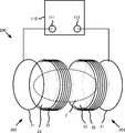
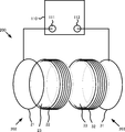
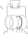
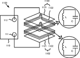
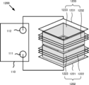
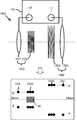
- the method for forming a magnetic field space according to the present invention is realized by, for example, a wireless power supply system 200 as shown in FIG.
- the wireless power supply system 200 includes a power supply module 202 including a power supply coil 21 and a power supply resonator 22 and a power reception module 203 including a power reception coil 31 and a power reception resonator 32 as main components, and the power supply resonator 22 and the power reception resonator.
- a solenoid type coil is used, and the power feeding resonator 22 and the power receiving resonator 32 are arranged such that the coil surface of the power feeding resonator 22 and the coil surface of the power receiving resonator 32 face each other. Yes.
- a cylindrical magnetic member 23 that covers the entire coil inner peripheral surface of the power supply resonator 22 is disposed on the coil inner peripheral surface side of the power supply resonator 22.
- a cylindrical magnetic member 33 that covers the entire coil inner peripheral surface of the power receiving resonator 32 is also disposed on the coil inner peripheral surface side of the power receiving resonator 32.
- the feeding coil 21 of the feeding module 202 and an output terminal 111 of the network analyzer 110 described later are connected by wiring so that AC power can be output from the output terminal 111 to the feeding coil 21 at an arbitrary frequency.
- the power receiving coil 31 of the power receiving module 203 and the input terminal 112 of the network analyzer 110 are connected by wiring so that the power input from the power receiving coil 31 to the input terminal 112 can be measured. Then, power is transmitted by changing the magnetic field from the power supply resonator 22 of the power supply module 202 to the power reception resonator 32 of the power reception module 203 by using a resonance phenomenon, so that the power supply resonator 22 and the power reception resonator 32 are surrounded. The generated magnetic field is blocked by the magnetic members 23 and 33, and the magnetic field strength is higher on the coil inner peripheral surface side (desired position) of the power feeding resonator 22 and the power receiving resonator 32 than the magnetic field strength other than the coil inner peripheral surface side. A small magnetic field space Z is formed.
- the power supply resonator 22 and the power reception resonator 32 are, for example, a resonator using a coil, and examples thereof include spiral type, solenoid type, and loop type coils.
- the resonance phenomenon means that two or more coils are tuned at the resonance frequency.
- the phrase “coil and coil are arranged to face each other” means that the coils are arranged face-to-face so that the coil surfaces are not orthogonal to each other with the radial cross section of the coil as a coil surface.
- the desired position refers to a space on the inner peripheral side or outer peripheral side of the coil (power feeding resonator 22) in the power feeding module 202 or the coil (power receiving resonator 32) in the power receiving module 203.
- the power feeding resonator 22 in the power feeding module 202 and the power receiving resonator 32 in the power receiving module 203 are arranged to face each other, and at least a part of the surfaces excluding these facing surfaces are arranged.
- a magnetic field space Z formed by the above-described wireless power supply system in which a magnetic member is arranged so as to be covered will be described as a first example by measuring the magnetic field strengths of the comparative example and examples 1 to 3.
- the measurement is performed using the wireless power supply systems 100, 200, 300, and 400 that are changed according to the comparative example and the first to third embodiments (FIGS. 2, 5, and 5). (Refer FIG. 8, FIG. 11).
- the change in the magnetic field strength when the metal piece is inserted and the case where the metal piece is not inserted and the change in the transmission characteristic “S21” to be described later are measured.
- wireless power including cylindrical magnetic members 23 and 33 covering the entire inner peripheral surfaces of the coils of the power supply resonator 22 and the power reception resonator 32.
- the magnetic field space Z formed by the supply system 200 the change in magnetic field strength and the change in the transmission characteristic “S21” when the metal piece is inserted into the coil inner circumference side of the power receiving resonator 32 and when the metal piece is not inserted. Measure.
- Example 2 in the power feeding module 302 and the power receiving module 303 illustrated in FIG. 8, cylindrical magnetic members 23 and 33 that cover the entire inner peripheral surfaces of the coils of the power feeding resonator 22 and the power receiving resonator 32, and the power feeding resonator 22 and the magnetic field space Z formed by the wireless power supply system 300 including the cylindrical magnetic members 24 and 34 covering the entire outer peripheral surface of the coil of the power receiving resonator 32, a metal is formed on the inner peripheral side of the coil of the power receiving resonator 32. A change in magnetic field strength and a change in transmission characteristic “S21” are measured when the piece is inserted and when the metal piece is not inserted.
- Example 3 in the power supply module 402 and the power reception module 403 shown in FIG. 11, cylindrical magnetic members 23 and 33 that cover the entire inner peripheral surfaces of the coils of the power supply resonator 22 and the power reception resonator 32, and the power supply resonator 22 and the cylindrical magnetic members 24 and 34 covering the entire outer peripheral surface of the coil of the power receiving resonator 32, and the ring-shaped magnetic member 25 covering the side surface opposite to the coil facing surface of the power feeding resonator 22 and the power receiving resonator 32.
- the wireless power supply system 100 used in the comparative example includes a power supply module 102 including a power supply coil 21 and a power supply resonator 22, and a power reception module 103 including a power reception coil 31 and a power reception resonator 32.
- the power supply coil 21 is connected to an output terminal 111 of a network analyzer 110 (manufactured by Agilent Technologies).
- the power receiving coil 31 is connected to the input terminal 112 of the network analyzer 110.
- the wireless power supply system 100 configured as described above when power is supplied to the power supply module 102, power is supplied from the power supply resonator 22 to the power reception resonator 32 as magnetic field energy by a resonance phenomenon.
- the network analyzer 110 can output AC power from the output terminal 111 to the feeding coil 21 at an arbitrary frequency.
- the network analyzer 110 can measure the power input from the power receiving coil 31 to the input terminal 112. Further, the network analyzer 110 can measure the transmission characteristic “S21” shown in FIG.
- the power supply coil 21 serves to supply the power obtained from the network analyzer 110 to the power supply resonator 22 by electromagnetic induction.
- the feeding coil 21 is set to a coil diameter of 100 mm ⁇ by winding a copper wire (with an insulating coating) having a diameter of 1 mm ⁇ once.
- the power receiving coil 31 plays a role of outputting electric power transmitted from the power feeding resonator 22 to the power receiving resonator 32 as magnetic field energy to the input terminal 112 of the network analyzer 110 by electromagnetic induction. Similar to the power feeding coil 21, the power receiving coil 31 is set to a coil diameter of 100 mm ⁇ by winding a copper wire (with an insulating coating) having a wire diameter of 1 mm ⁇ once.
- Each of the power feeding resonator 22 and the power receiving resonator 32 is an LC resonance circuit and plays a role of creating a magnetic field resonance state.
- the capacitor component of the LC resonance circuit is realized by an element, but may be realized by a stray capacitance with both ends of the coil being opened.
- the power feeding resonator 22 and the power receiving resonator 32 are solenoid type coils having a coil diameter of 100 mm ⁇ , which is formed by winding a copper wire (with an insulating coating) having a wire diameter of 1 mm ⁇ three times.
- the power feeding resonator 22 and the power receiving resonator 32 have a resonance frequency of 13.0 MHz.
- the power feeding resonator 22 and the power receiving resonator 32 are arranged so that the coil surface of the power feeding resonator 22 and the coil surface of the power receiving resonator 32 face each other in parallel.
- a magnetic field resonance state is created between the power supply resonator 22 and the power reception resonator 32. be able to.
- electric power can be transmitted from the power feeding resonator 22 to the power receiving resonator 32 as magnetic field energy.
- the distance A between the power feeding coil 21 and the power feeding resonator 22 is set to 15 mm
- the distance B between the power receiving coil 31 and the power receiving resonator 32 is set to 15 mm
- the distance C to 32 is set to 30 mm (see FIG. 2).
- the metal piece inserted into the inner periphery of the coil of the power receiving resonator 32 has a thickness of 20 mm and a diameter of 76 mm ⁇ .
- a circular aluminum piece 60 made of aluminum is used.
- the circular aluminum piece 60 made of aluminum having a thickness of 20 mm and a diameter of 58 mm ⁇ is used.
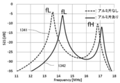
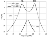
- the transmission characteristic “S 21” when the aluminum piece 60 is not inserted on the inner peripheral side of the coil of the power receiving resonator 32 is expressed as the wireless power Measurement is performed while changing the frequency of the AC power supplied to the supply system 100.
- the horizontal axis is measured as the frequency of the AC power output from the output terminal 111
- the vertical axis is measured as the transmission characteristic “S21”.
- the transmission characteristic “S21” represents a signal that passes through the input terminal 112 when a signal is input from the output terminal 111, and is displayed in decibels.
- the power transmission efficiency refers to the ratio of the power output from the input terminal 112 to the power supplied from the output terminal 111 to the power supply module in a state where the wireless power supply system 101 is connected to the network analyzer 110. That is, the higher the transmission characteristic “S21”, the higher the power transmission efficiency.
- the peak is separated into the low frequency side and the high frequency side.
- the frequency on the high frequency side is expressed as fH
- the frequency on the low frequency side is expressed as fL.
- the power supply resonator 22 and the power reception resonator 32 enter the resonance state in the same phase.
- the direction of the current flowing through the power feeding resonator 22 is the same as the direction of the current flowing through the power receiving resonator 32.
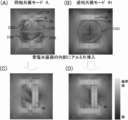
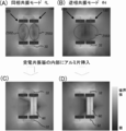
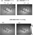
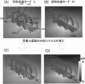
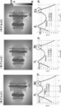
- the magnetic field strength distribution in this in-phase resonance mode is shown in FIG. From the magnetic field strength distribution of FIG. 4A, the magnetic field space Z151 having a relatively small magnetic field strength can be confirmed on the outer peripheral side of the power feeding resonator 22 and the power receiving resonator 32 by reducing the influence of the magnetic field. .
- an in-phase resonance mode a resonance state in which the direction of the current flowing in the coil (power feeding resonator 22) in the power feeding module and the direction of the current flowing in the coil (power receiving resonator 32) in the power receiving module are the same is referred to as an in-phase resonance mode. To do.
- FIG. 4B shows the magnetic field strength distribution in this reversed phase resonance mode. From the magnetic field strength distribution of FIG. 4B, the magnetic field space Z153 having a relatively small magnetic field strength can be confirmed on the inner peripheral side of the power feeding resonator 22 and the power receiving resonator 32 by reducing the influence of the magnetic field. it can.
- a resonance state in which the direction of the current flowing in the coil (power feeding resonator 22) in the power feeding module and the direction of the current flowing in the coil (power receiving resonator 32) in the power receiving module are opposite to each other is referred to as an anti-phase resonance mode.
- the transmission characteristic “S21” when the aluminum piece 60 is inserted on the coil inner peripheral side of the power receiving resonator 32 is the AC power supplied to the wireless power supply system 100. Measure while changing the frequency.
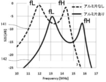
- the measurement result is shown in FIG. 3 as a measurement waveform 142 of the transmission characteristic “S21” when the aluminum piece 60 is inserted on the inner circumference side of the coil of the power receiving resonator 32.
- the transmission characteristic “S 21” at the frequency fL near the peak on the low frequency side is the measured waveform 141 of the transmission characteristic “S 21” when the aluminum piece 60 is not inserted on the inner peripheral side of the coil of the power receiving resonator 32.
- the transmission characteristic “S21” at the frequency fH near the peak on the high frequency side is also compared with the measured waveform 141 of the transmission characteristic “S21” when the aluminum piece 60 is not inserted on the inner peripheral side of the coil of the power receiving resonator 32. It turns out that it falls remarkably.
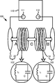
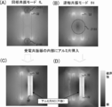
- FIG. 4C shows the magnetic field strength distribution in the in-phase resonance mode when the aluminum piece 60 is inserted on the inner circumference side of the coil of the power receiving resonator 32.
- FIG. 4D shows the magnetic field strength distribution in the anti-phase resonance mode when the aluminum piece 60 is inserted on the inner circumference side of the coil of the power receiving resonator 32.
- the magnetic field strength distribution when the aluminum piece 60 is inserted on the inner circumferential side of the coil of the power receiving resonator 32 is directly affected by the aluminum piece 60. I understand. In other words, it can be seen that the aluminum piece 60 is directly affected by the magnetic field generated in the wireless power supply system 100.
- the wireless power supply system 200 used in the first embodiment includes a power supply coil 21, a power supply resonator 22, and a cylindrical magnetic member 23 that covers the entire inner peripheral surface of the power supply resonator 22.
- the power supply module 202 includes a power receiving coil 31, a power receiving resonator 32, and a power receiving module 203 including a cylindrical magnetic member 33 that covers the entire inner peripheral surface of the power receiving resonator 32.
- the power supply coil 21 is connected to the output terminal 111 of the network analyzer 110
- the power receiving coil 31 is connected to the input terminal 112 of the network analyzer 110.
- the magnetic members 23 and 33 are formed of a resin in which magnetic powder is dispersed.
- the resin used for the magnetic members 23 and 33 may be a thermosetting resin or a thermoplastic resin, and is not particularly limited.
- thermosetting resin an epoxy resin, a phenol resin, a melamine resin, a vinyl ester resin, a cyano ester resin, a maleimide resin, a silicon resin, etc.
- thermoplastic resins include acrylic resins, vinyl acetate resins, polyvinyl alcohol resins, and the like.
- a resin mainly composed of an epoxy resin is used.
- soft magnetic powder is used as the magnetic powder dispersed in the resin.
- the soft magnetic powder is not particularly limited, but pure Fe, Fe-Si, Fe-Al-Si (Sendust), Fe-Ni (Permalloy), soft ferrite, Fe-based amorphous, Co-based amorphous, Fe -Co (permendule) can be used.
- the magnetic members 23 and 33 have a cylindrical shape with a thickness of 1 mm, an outer diameter of 80 mm ⁇ , and an inner diameter of 78 mm, and the magnetic permeability is 100.
- Other configurations are the same as those of the wireless power supply system 100 according to the comparative example.
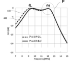
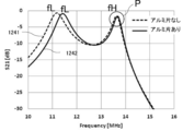
- the transmission characteristic “S21” when the aluminum piece 60 is not inserted on the inner peripheral side of the coil of the power receiving resonator 32 is wirelessly Measurement is performed while changing the frequency of the AC power supplied to the power supply system 200.
- the peak is separated into the low frequency side and the high frequency side.
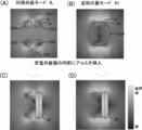
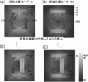
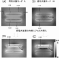
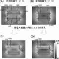
- FIG. 7A shows the magnetic field strength distribution when the frequency of the AC power supplied to the power supply module 202 is set to the frequency fL near the peak on the low frequency side (in-phase resonance mode).
- the magnetic field space Z251 having a relatively small magnetic field strength can be confirmed on the outer peripheral side of the power feeding resonator 22 and the power receiving resonator 32 by reducing the influence of the magnetic field.
- a magnetic field space Z252 having a magnetic field intensity slightly reduced by the influence of the magnetic field can be confirmed on the inner peripheral side of the power feeding resonator 22 and the power receiving resonator 32.
- a magnetic field space Z252 having a smaller magnetic field strength than that of the comparative example can be formed on the inner peripheral side of the power feeding resonator 22 and the power receiving resonator 32.
- FIG. 7B shows the magnetic field strength distribution when the frequency of AC power supplied to the power supply module 202 is set to the frequency fH near the peak on the high frequency side (reverse phase resonance mode). From the magnetic field strength distribution of FIG. 7B, it is possible to confirm the magnetic field space Z253 having a relatively small magnetic field strength on the inner peripheral side of the power feeding resonator 22 and the power receiving resonator 32 by reducing the influence of the magnetic field. it can. Thus, in the antiphase resonance mode, the magnetic field space Z253 having a smaller magnetic field strength than that of the comparative example can be formed on the inner peripheral side of the power feeding resonator 22 and the power receiving resonator 32. The magnetic field space Z253 formed in the anti-phase resonance mode can be formed wider than the magnetic field space Z252 formed in the in-phase resonance mode.
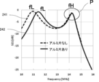
- the measurement result is shown in FIG. 6 as a measurement waveform 242 of the transmission characteristic “S21” when the aluminum piece 60 is inserted on the inner circumference side of the coil of the power receiving resonator 32.
- the transmission characteristic “S21” at the frequency fL near the peak on the low frequency side is the measurement waveform 241 of the transmission characteristic “S21” when the aluminum piece 60 is not inserted on the inner peripheral side of the coil of the power receiving resonator 32. It can be seen that the value of the transmission characteristic is maintained at a high value, although it is slightly lower than that of.
- the transmission characteristic “S21” at the frequency fH near the peak on the high frequency side is almost the same as the measured waveform 241 of the transmission characteristic “S21” when the aluminum piece 60 is not inserted on the inner peripheral side of the coil of the power receiving resonator 32. It can be seen that the same value is maintained (see point P in FIG. 6).
- FIG. 7C shows the magnetic field strength distribution in the in-phase resonance mode when the aluminum piece 60 is inserted on the inner peripheral side of the coil of the power receiving resonator 32.
- FIG. 7D shows the magnetic field strength distribution in the anti-phase resonance mode when the aluminum piece 60 is inserted on the inner peripheral side of the coil of the power receiving resonator 32.
- a magnetic field space Z253 larger than the magnetic field space Z153 according to the comparative example can be formed on the inner peripheral side of the coil of the power receiving resonator 32. Further, it can be said that the influence of the magnetic field generated in the wireless power supply system 200 is reduced on the aluminum piece 60.
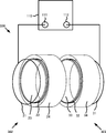
- the wireless power supply system 300 used in the second embodiment includes a power supply coil 21, a power supply resonator 22, a cylindrical magnetic member 23 that covers the entire inner peripheral surface of the power supply resonator 22, and A power supply module 302 including a cylindrical magnetic member 24 that covers the entire outer peripheral surface of the coil of the power supply resonator 22, and a cylindrical magnetic member that covers the entire inner peripheral surface of the power receiving coil 31, the power receiving resonator 32, and the power receiving resonator 32. 33 and a power receiving module 303 including a cylindrical magnetic member 34 that covers the entire outer peripheral surface of the coil of the power receiving resonator 32.
- the power supply coil 21 is connected to the output terminal 111 of the network analyzer 110
- the power receiving coil 31 is connected to the input terminal 112 of the network analyzer 110.
- the magnetic members 24 and 34 are formed of a resin in which magnetic powder is dispersed, like the magnetic members 23 and 33 of the first embodiment.
- the magnetic members 24 and 34 have a cylindrical shape with a thickness of 1 mm, an outer diameter of 120 mm ⁇ , and an inner diameter of 118 mm ⁇ , and have a magnetic permeability of 100.
- Other configurations are the same as those of the wireless power supply system 200 according to the first embodiment.
- the transmission characteristic “S21” when the aluminum piece 60 is not inserted on the inner peripheral side of the coil of the power receiving resonator 32 is wirelessly Measurement is performed while changing the frequency of the AC power supplied to the power supply system 300.
- the peak is separated into the low frequency side and the high frequency side.
- FIG. 10A shows the magnetic field strength distribution when the frequency of the AC power supplied to the power supply module 302 is set to the frequency fL near the peak on the low frequency side (in-phase resonance mode). From the magnetic field strength distribution of FIG. 10A, a magnetic field space Z352 having a magnetic field strength slightly reduced by the influence of the magnetic field can be confirmed on the inner peripheral side of the power feeding resonator 22 and the power receiving resonator 32. Thus, in the in-phase resonance mode, a magnetic field space Z352 having a smaller magnetic field strength than that of the comparative example can be formed on the inner peripheral side of the power feeding resonator 22 and the power receiving resonator 32.
- FIG. 10B shows the magnetic field strength distribution when the frequency of AC power supplied to the power supply module 302 is set to the frequency fH near the peak on the high frequency side (reverse phase resonance mode).
- the magnetic field space Z353 having a relatively small magnetic field strength can be confirmed on the inner peripheral side of the power feeding resonator 22 and the power receiving resonator 32 by reducing the influence of the magnetic field. it can.
- the magnetic field space Z353 having a smaller magnetic field strength than that of the comparative example can be formed on the inner peripheral side of the power feeding resonator 22 and the power receiving resonator 32.
- the magnetic field space Z353 formed in the anti-phase resonance mode can be formed wider than the magnetic field space Z352 formed in the in-phase resonance mode.
- the AC power supplied to the wireless power supply system 300 with the transmission characteristic “S21” when the aluminum piece 60 is inserted on the inner circumference side of the coil of the power receiving resonator 32 is used. Measure while changing the frequency.
- the measurement result is shown in FIG. 9 as a measurement waveform 342 of the transmission characteristic “S21” when the aluminum piece 60 is inserted on the inner circumference side of the coil of the power receiving resonator 32.
- the transmission characteristic “S21” at the frequency fL near the peak on the low frequency side is the measured waveform 341 of the transmission characteristic “S21” when the aluminum piece 60 is not inserted on the inner peripheral side of the coil of the power receiving resonator 32. It can be seen that the value of the transmission characteristic is maintained at a high value, although it is slightly lower than that of.
- the transmission characteristic “S21” at the frequency fH near the peak on the high frequency side is almost the same as the measured waveform 341 of the transmission characteristic “S21” when the aluminum piece 60 is not inserted on the inner peripheral side of the coil of the power receiving resonator 32. It can be seen that the same value is maintained (see point P in FIG. 9).
- FIG. 10C shows the magnetic field strength distribution in the in-phase resonance mode when the aluminum piece 60 is inserted on the inner peripheral side of the coil of the power receiving resonator 32.
- FIG. 10D shows the magnetic field strength distribution in the anti-phase resonance mode when the aluminum piece 60 is inserted on the inner peripheral side of the coil of the power receiving resonator 32.
- a magnetic field space Z353 larger than the magnetic field space Z153 according to the comparative example can be formed on the inner peripheral side of the coil of the power feeding resonator 22 and the power receiving resonator 32. Further, it can be said that the influence of the magnetic field generated in the wireless power supply system 300 is reduced on the aluminum piece 60.
- the magnetic field space Z353 formed by the wireless power supply system 300 according to the second embodiment is wider than the magnetic field space Z253 formed by the wireless power supply system 200 according to the first embodiment. This is because, in the wireless power supply system 300 according to the second embodiment, the cylindrical magnetic members 24 and 34 that cover the entire outer peripheral surfaces of the power feeding resonator 22 and the power receiving resonator 32 are provided. This is because the magnetic field generated on the outer peripheral side of 22 and the power receiving resonator 32 is blocked.
- the wireless power supply system 400 used in the third embodiment has a cylindrical shape that covers the entire inner peripheral surface of the power supply coil 21, the power supply resonator 22, and the power supply coil 21 and the power supply resonator 22.
- a magnetic member 23, a cylindrical magnetic member 24 that covers the entire coil outer peripheral surface of the power feeding coil 21 and the power feeding resonator 22, and a ring-shaped magnetic member 25 that covers a side surface opposite to the coil facing surface of the power feeding resonator 22 are provided.
- the power supply coil 21 is connected to the output terminal 111 of the network analyzer 110
- the power receiving coil 31 is connected to the input terminal 112 of the network analyzer 110.
- the magnetic members 25 and 35 are formed of a resin in which magnetic powder is dispersed, like the magnetic members 23 and 33 of the first embodiment.
- the magnetic members 25 and 35 have an O-ring shape with a thickness of 1 mm, an outer diameter of 120 mm, and an inner diameter of 80 mm, and the magnetic permeability is 100.
- Other configurations are the same as those of the wireless power supply system 300 according to the second embodiment.
- the transmission characteristic “S21” when the aluminum piece 60 is not inserted on the inner peripheral side of the coil of the power receiving resonator 32 is wirelessly Measurement is performed while changing the frequency of the AC power supplied to the power supply system 400.
- the peak is separated into the low frequency side and the high frequency side.
- FIG. 13A shows the magnetic field strength distribution when the frequency of the alternating current power supplied to the power supply module 402 is set to the frequency fL near the peak on the low frequency side (in-phase resonance mode). From the magnetic field strength distribution of FIG. 13A, a magnetic field space Z452 having a magnetic field strength slightly reduced by the influence of the magnetic field can be confirmed on the inner peripheral side of the power feeding resonator 22 and the power receiving resonator 32. Thus, in the in-phase resonance mode, the magnetic field space Z452 having a smaller magnetic field strength than the comparative example can be formed on the inner peripheral side of the power feeding resonator 22 and the power receiving resonator 32.
- FIG. 13B shows the magnetic field strength distribution when the frequency of AC power supplied to the power supply module 402 is set to the frequency fH near the peak on the high frequency side (reverse phase resonance mode).
- the magnetic field space Z453 having a relatively small magnetic field strength can be confirmed on the inner peripheral side of the power feeding resonator 22 and the power receiving resonator 32 by reducing the influence of the magnetic field. it can.
- the magnetic field space Z453 having a smaller magnetic field strength than that of the comparative example can be formed on the inner peripheral side of the power feeding resonator 22 and the power receiving resonator 32.
- the magnetic field space Z453 formed in the anti-phase resonance mode can be formed wider than the magnetic field space Z452 formed in the in-phase resonance mode.
- the measurement result is shown in FIG. 12 as a measurement waveform 442 of the transmission characteristic “S21” when the aluminum piece 60 is inserted on the inner circumference side of the coil of the power receiving resonator 32.
- the transmission characteristic “S21” at the frequency fL near the peak on the low frequency side is the measurement waveform 441 of the transmission characteristic “S21” when the aluminum piece 60 is not inserted on the inner peripheral side of the coil of the power receiving resonator 32. It can be seen that almost the same value is maintained compared to.
- the transmission characteristic “S21” at the frequency fH near the peak on the high frequency side is almost the same as the measured waveform 441 of the transmission characteristic “S21” when the aluminum piece 60 is not inserted on the inner peripheral side of the coil of the power receiving resonator 32. It can be seen that the same value is maintained (see point P in FIG. 12).
- FIG. 13C shows the magnetic field strength distribution in the in-phase resonance mode when the aluminum piece 60 is inserted on the inner circumference side of the coil of the power receiving resonator 32.
- FIG. 13D shows the magnetic field strength distribution in the anti-phase resonance mode when the aluminum piece 60 is inserted on the inner peripheral side of the coil of the power receiving resonator 32.
- magnetic fields generated around the power supply resonator 22 and the power reception resonator 32 are generated as magnetic members 23 and 33, magnetic members 24 and 34, and magnetic members.
- the magnetic field space Z453 larger than the magnetic field space Z153 according to the comparative example can be formed on the coil inner peripheral side of the power feeding resonator 22 and the power receiving resonator 32 by being cut off by 25 and 35. Further, it can be said that the influence of the magnetic field generated in the wireless power supply system 400 is reduced on the aluminum piece 60.
- the magnetic field space Z453 formed by the wireless power supply system 400 according to the third embodiment is wider than the magnetic field space Z353 formed by the wireless power supply system 300 according to the second embodiment.
- the magnetic members 25 and 35 that cover the side surfaces of the power feeding resonator 22 and the power receiving resonator 32 are provided, and thus the power feeding resonator 22 and the power receiving resonator 32 are provided. This is because the magnetic field generated on the side surface of the film is cut off.
- the wireless power supply system 500 according to the fourth embodiment uses the magnetic members 123 and 133 in which the thickness of the magnetic members 23 and 33 in the wireless power supply system 200 according to the first embodiment is increased from 1 mm to 10 mm.
- the other configuration is the same as that of the first embodiment (see FIG. 15). Then, with respect to the magnetic field space Z formed by the wireless power supply system 500, the change in magnetic field strength when the aluminum piece 60 is inserted into the coil inner peripheral side of the power receiving resonator 32 and when the aluminum piece 60 is not inserted, and The change of the transmission characteristic “S21” is measured.
- the measured waveform 541 of the measured transmission characteristic “S21” has peaks separated on the low frequency side and the high frequency side.
- FIG. 15A shows the magnetic field intensity distribution when the frequency of the alternating current power supplied to the power supply module 502 is set to the frequency fL near the peak on the low frequency side (common mode resonance mode). From the magnetic field strength distribution of FIG. 15A, a magnetic field space Z552 having a magnetic field strength in which the influence of the magnetic field is reduced can be confirmed on the inner peripheral side of the power feeding resonator 22 and the power receiving resonator 32. Moreover, in the wireless power supply system 500 according to the fourth embodiment, the magnetic field space Z252 formed by the wireless power supply system 200 according to the first embodiment on the inner peripheral side of the power feeding resonator 22 and the power receiving resonator 32 in the in-phase resonance mode. A wider magnetic field space Z552 can be formed.
- the magnetic members 123 and 133 covering the inner peripheral surfaces of the power feeding resonator 22 and the power receiving resonator 32 are thicker than those in the first embodiment. This is because the magnetic fields generated on the inner peripheral surfaces of the power feeding resonator 22 and the power receiving resonator 32 are more reliably cut off.
- FIG. 15B shows the magnetic field strength distribution when the frequency of AC power supplied to the power supply module 502 is set to the frequency fH near the peak on the high frequency side (reverse phase resonance mode).
- the magnetic field space Z553 having a relatively small magnetic field strength can be confirmed on the inner peripheral side of the power feeding resonator 22 and the power receiving resonator 32 by reducing the influence of the magnetic field. it can.
- a wider magnetic field space Z553 than the magnetic field space Z253 formed by the wireless power supply system 200 according to the first embodiment is formed on the inner peripheral side of the power feeding resonator 22 and the power receiving resonator 32. Can be formed.
- the magnetic members 123 and 133 covering the inner peripheral surfaces of the power feeding resonator 22 and the power receiving resonator 32 are thicker than those in the first embodiment. This is because the magnetic fields generated on the inner peripheral surfaces of the power feeding resonator 22 and the power receiving resonator 32 are more reliably cut off.
- the magnetic field space Z553 formed in the anti-phase resonance mode can be formed wider than the magnetic field space Z552 formed in the in-phase resonance mode.
- the AC power supplied to the wireless power supply system 500 with the transmission characteristic “S21” when the aluminum piece 60 is inserted on the inner circumferential side of the coil of the power receiving resonator 32 is used. Measure while changing the frequency.
- the measurement result is shown in FIG. 14 as a measurement waveform 542 of the transmission characteristic “S21” when the aluminum piece 60 is inserted on the inner circumference side of the coil of the power receiving resonator 32.
- the transmission characteristic “S21” at the frequency fL near the peak on the low frequency side is the measurement waveform 541 of the transmission characteristic “S21” when the aluminum piece 60 is not inserted on the inner peripheral side of the coil of the power receiving resonator 32. It can be seen that substantially the same value is maintained (see point P1 in FIG. 14).
- the transmission characteristic “S21” at the frequency fH near the peak on the high frequency side is almost the same as the measured waveform 541 of the transmission characteristic “S21” when the aluminum piece 60 is not inserted on the inner peripheral side of the coil of the power receiving resonator 32. It can be seen that the same value is maintained (see point P2 in FIG. 14).
- FIG. 15C shows the magnetic field strength distribution in the in-phase resonance mode when the aluminum piece 60 is inserted on the inner peripheral side of the coil of the power receiving resonator 32.
- FIG. 15D shows the magnetic field strength distribution in the anti-phase resonance mode when the aluminum piece 60 is inserted on the inner peripheral side of the coil of the power receiving resonator 32.
- the magnetic field strength distribution when the aluminum piece 60 is inserted on the inner circumferential side of the coil of the power receiving resonator 32 is higher than that of the first embodiment. It can be seen that there is almost no influence.
- the power feeding resonator 22 is used when power is transmitted between the power feeding module 502 and the power receiving module 503.
- relatively large magnetic field spaces Z552 and Z553 can be formed on the inner peripheral side of the coil of the power receiving resonator 32.
- the wireless power supply system 600 uses the magnetic members 123 and 133 in which the thickness of the magnetic members 23 and 33 in the wireless power supply system 300 according to the second embodiment is increased from 1 mm to 10 mm.
- the other configuration is the same as that of the second embodiment (see FIG. 17). Then, with respect to the magnetic field space Z formed by the wireless power supply system 600, the change in magnetic field strength when the aluminum piece 60 is inserted on the coil inner peripheral side of the power receiving resonator 32 and when the aluminum piece 60 is not inserted, and The change of the transmission characteristic “S21” is measured.
- the peak is separated into the low frequency side and the high frequency side.
- FIG. 17A shows a magnetic field strength distribution when the frequency of the alternating current power supplied to the power supply module 602 is set to the frequency fL near the peak on the low frequency side (common mode resonance mode). From the magnetic field strength distribution of FIG. 17A, a magnetic field space Z652 having a magnetic field strength that is less affected by the magnetic field can be confirmed on the inner peripheral side of the power feeding resonator 22 and the power receiving resonator 32. Moreover, in the wireless power supply system 600 according to the fifth embodiment, the magnetic field space Z352 formed by the wireless power supply system 300 according to the second embodiment on the inner peripheral side of the power feeding resonator 22 and the power receiving resonator 32 in the in-phase resonance mode. A wider magnetic field space Z652 can be formed.
- the magnetic members 123 and 133 covering the inner peripheral surfaces of the power feeding resonator 22 and the power receiving resonator 32 are thicker than those in the second embodiment. This is because the magnetic fields generated on the inner peripheral surfaces of the power feeding resonator 22 and the power receiving resonator 32 are more reliably cut off.
- FIG. 17B shows the magnetic field strength distribution when the frequency of AC power supplied to the power supply module 602 is set to the frequency fH near the peak on the high frequency side (reverse phase resonance mode).
- the magnetic field space Z653 having a relatively small magnetic field strength can be confirmed on the inner peripheral side of the power feeding resonator 22 and the power receiving resonator 32 by reducing the influence of the magnetic field. it can.
- a wider magnetic field space Z653 than the magnetic field space Z353 formed by the wireless power supply system 300 according to the second embodiment is formed on the inner peripheral side of the power feeding resonator 22 and the power receiving resonator 32. Can be formed.
- the magnetic members 123 and 133 covering the inner peripheral surfaces of the power feeding resonator 22 and the power receiving resonator 32 are thicker than those in the second embodiment. This is because the magnetic fields generated on the inner peripheral surfaces of the power feeding resonator 22 and the power receiving resonator 32 are more reliably cut off.
- the magnetic field space Z653 formed in the anti-phase resonance mode can be formed wider than the magnetic field space Z652 formed in the in-phase resonance mode.
- the AC power supplied to the wireless power supply system 600 with the transmission characteristic “S21” when the aluminum piece 60 is inserted on the inner peripheral side of the coil of the power receiving resonator 32 is used. Measure while changing the frequency.
- the measurement result is shown in FIG. 16 as a measurement waveform 642 of the transmission characteristic “S21” when the aluminum piece 60 is inserted on the inner circumference side of the coil of the power receiving resonator 32.
- the transmission characteristic “S21” at the frequency fL near the peak on the low frequency side is the measurement waveform 641 of the transmission characteristic “S21” when the aluminum piece 60 is not inserted on the inner peripheral side of the coil of the power receiving resonator 32. It can be seen that substantially the same value is maintained (see point P1 in FIG. 16).
- the transmission characteristic “S21” at the frequency fH near the peak on the high frequency side is almost the same as the measured waveform 641 of the transmission characteristic “S21” when the aluminum piece 60 is not inserted on the inner peripheral side of the coil of the power receiving resonator 32. It can be seen that the same value is maintained (see point P2 in FIG. 16).
- FIG. 17C shows the magnetic field strength distribution in the in-phase resonance mode when the aluminum piece 60 is inserted on the inner circumference side of the coil of the power receiving resonator 32.
- FIG. 17D shows the magnetic field strength distribution in the anti-phase resonance mode when the aluminum piece 60 is inserted on the inner circumference side of the coil of the power receiving resonator 32.
- the magnetic field strength distribution when the aluminum piece 60 is inserted on the inner circumferential side of the coil of the power receiving resonator 32 is higher than that of the second embodiment. It can be seen that there is almost no influence.
- the power feeding resonator 22 is used when power is transmitted between the power feeding module 602 and the power receiving module 603.
- relatively large magnetic field spaces Z652 and Z653 can be formed on the inner circumference side of the coil of the power receiving resonator 32.
- a rectangular column-shaped cylinder in which a power supply resonator in a power supply module and a power reception resonator in a power reception module are arranged to face each other and the entire inner peripheral surface of the power supply resonator and the power reception resonator are covered with the inner peripheral surface of the coil.
- a magnetic field space Z formed by a wireless power supply system in which a magnetic member is arranged will be described as a second embodiment by measuring the magnetic field strength and the like.
- the change of the transmission characteristic “S21” and the magnetic field when the aluminum piece 60 is inserted into the coil inner periphery of the power receiving resonator 1132 and when the aluminum piece 60 is not inserted Measure the change in intensity.
- the entire inner peripheral surfaces of the coils of the power supply resonator 1222 and the power reception resonator 1232 are covered.
- the magnetic field space Z formed by the wireless power supply system 1200 including the quadrangular columnar cylindrical magnetic members 1223 and 1233 when the aluminum piece 60 is inserted into the coil inner peripheral side of the power receiving resonator 1232 and the aluminum piece 60 The change of the transmission characteristic “S21” and the change of the magnetic field strength when no is inserted are measured.
- a wireless power supply system 1100 used in the second comparative example includes a power supply module 1102 including a power supply coil 1121 having a rectangular shape and a power supply resonator 1122 having a quadrangular prism-shaped cylindrical coil structure. And a power receiving module 1103 including a power receiving coil 1131 having a quadrangular shape and a power receiving resonator 1132 having a quadrangular columnar cylindrical coil structure.
- the power supply coil 1121 is connected to the output terminal 111 of the network analyzer 110
- the power receiving coil 1131 is connected to the input terminal 112 of the network analyzer 110.
- the feeding coil 1121 plays a role of supplying the power obtained from the network analyzer 110 to the feeding resonator 1122 by electromagnetic induction.
- This power supply coil 1121 is made of a copper wire (with an insulating coating) having a wire diameter of 1 mm.
- the power receiving coil 1131 plays a role of outputting electric power transmitted from the power feeding resonator 1122 to the power receiving resonator 1132 as magnetic field energy to the input terminal 112 of the network analyzer 110 by electromagnetic induction. Similar to the power feeding coil 1121, the power receiving coil 1131 is made of a copper wire (with an insulating coating) having a wire diameter of 1 mm ⁇ once and formed into a square shape having a side of 100 mm.
- the power feeding resonator 1122 and the power receiving resonator 1132 are each an LC resonance circuit and play a role of creating a magnetic field resonance state.
- the power feeding resonator 1122 and the power receiving resonator 1132 have a rectangular column-shaped cylindrical coil structure in which a copper wire (with an insulating coating) having a wire diameter of 1 mm ⁇ is wound three times and a side is 100 mm.
- the distance between the power feeding coil 1121 and the power feeding resonator 1122 is set to 15 mm
- the distance between the power feeding resonator 1122 and the power receiving resonator 1132 is set to 30 mm
- the power receiving resonator 1132 and the power receiving coil 1131 are The distance between is set to 15 mm.
- the power feeding resonator 1122 and the power receiving resonator 1132 have a resonance frequency of 14.2 MHz.
- the power feeding resonator 1122 and the power receiving resonator 1132 are arranged such that the coil surface of the power feeding resonator 1122 and the coil surface of the power receiving resonator 1132 face each other in parallel.
- the metal piece inserted on the inner circumference side of the coil of the power receiving resonator 1132 is made of aluminum having a rectangular parallelepiped shape with a thickness of 20 mm and a side of 76 mm.
- An aluminum piece 60 is used.
- the transmission characteristic “S ⁇ b> 21” when the aluminum piece 60 is not inserted on the coil inner periphery side of the power receiving resonator 1132 is transmitted to the wireless power supply system 1100. Measure while changing the frequency of the supplied AC power.
- the peak is separated into the low frequency side and the high frequency side.
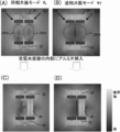
- FIG. 20A shows the magnetic field strength distribution in this in-phase resonance mode. From the magnetic field strength distribution of FIG. 20A, the magnetic field space Z1151 having a relatively small magnetic field strength can be confirmed on the outer peripheral side of the power feeding resonator 1122 and the power receiving resonator 1132 by reducing the influence of the magnetic field. .
- FIG. 20B shows the magnetic field strength distribution in the reverse phase resonance mode. From the magnetic field strength distribution of FIG. 20B, the magnetic field space Z1153 having a relatively small magnetic field strength can be confirmed on the inner peripheral side of the power feeding resonator 1122 and the power receiving resonator 1132 by reducing the influence of the magnetic field. it can.
- the transmission characteristic “S21” when the aluminum piece 60 is inserted on the inner circumference side of the coil of the power receiving resonator 1132 is changed. taking measurement.
- the measurement result is shown in FIG. 19 as a measurement waveform 1142 of the transmission characteristic “S21” when the aluminum piece 60 is inserted on the inner circumference side of the coil of the power receiving resonator 1132.
- the transmission characteristic “S21” at the frequency fL near the peak on the low frequency side is the measurement waveform 1141 of the transmission characteristic “S21” when the aluminum piece 60 is not inserted on the inner peripheral side of the coil of the power receiving resonator 1132.
- the transmission characteristic “S21” at the frequency fH near the peak on the high frequency side is also compared with the measured waveform 1141 of the transmission characteristic “S21” when the aluminum piece 60 is not inserted on the inner peripheral side of the coil of the power receiving resonator 1132. It turns out that it falls remarkably.
- FIG. 20C shows the magnetic field strength distribution in the in-phase resonance mode when the aluminum piece 60 is inserted on the inner circumference side of the coil of the power receiving resonator 1132.
- FIG. 20D shows the magnetic field strength distribution in the anti-phase resonance mode when the aluminum piece 60 is inserted on the inner peripheral side of the coil of the power receiving resonator 1132.
- a wireless power supply system 1200 used in the second embodiment includes a rectangular feeding coil 1221, a quadrangular prism-shaped cylindrical coil structure, a feeding resonator 1222, and a feeding resonator 1222.
- the output terminal 111 of the network analyzer 110 is connected to the feeding coil 1221, and the input terminal 112 of the network analyzer 110 is connected to the power receiving coil 1231.
- the magnetic members 1223 and 1233 are formed of a resin in which magnetic powder is dispersed.
- Each of the magnetic members 1223 and 1233 has a quadrangular cylindrical shape having a thickness of 1 mm, an outer side of 82 mm, an inner side of 80 mm, and a height of 30 mm.
- the magnetic permeability is 100.
- Other configurations such as the power feeding coil 1221, the power feeding resonator 1222, the power receiving coil 1231, and the power receiving resonator 1232 are the same as those of the wireless power supply system 1100 according to the second comparative example.
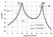
- the transmission characteristic “S ⁇ b> 21” when the aluminum piece 60 is not inserted on the coil inner periphery side of the power receiving resonator 1232 is transmitted to the wireless power supply system 1200. Measure while changing the frequency of the supplied AC power.
- the measured waveform 1241 of the measured transmission characteristic “S21” has peaks separated on the low frequency side and the high frequency side.
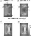
- FIG. 23A shows the magnetic field intensity distribution when the frequency of the alternating current power supplied to the power supply module 1202 is set to the frequency fL near the peak on the low frequency side (common mode resonance mode).
- the magnetic field space Z1251 having a relatively small magnetic field strength can be confirmed on the outer peripheral side of the power feeding resonator 1222 and the power receiving resonator 1232 by reducing the influence of the magnetic field.
- a magnetic field space Z1252 having a magnetic field strength slightly reduced by the influence of the magnetic field can be confirmed on the inner peripheral side of the power feeding resonator 1222 and the power receiving resonator 1232.
- a magnetic field space Z1252 having a smaller magnetic field strength than that of the second comparative example can be formed on the inner peripheral side of the power feeding resonator 1222 and the power receiving resonator 1232.
- FIG. 23B shows the magnetic field strength distribution when the frequency of AC power supplied to the power supply module 1202 is set to the frequency fH near the peak on the high frequency side (reverse phase resonance mode).
- the magnetic field space Z1253 having a relatively small magnetic field strength can be confirmed on the inner peripheral side of the power feeding resonator 1222 and the power receiving resonator 1232 by reducing the influence of the magnetic field. it can.
- the magnetic field space Z1253 having a smaller magnetic field strength than the second comparative example can be formed on the inner peripheral side of the power feeding resonator 1222 and the power receiving resonator 1232.
- the magnetic field space Z1253 formed in the anti-phase resonance mode can be formed wider than the magnetic field space Z1252 formed in the in-phase resonance mode.
- the transmission characteristic “S21” when the aluminum piece 60 is inserted on the inner circumference side of the coil of the power receiving resonator 1232 is changed while changing the frequency of the AC power supplied to the wireless power supply system 1200. taking measurement.
- the measurement result is shown in FIG. 22 as a measurement waveform 1242 of the transmission characteristic “S21” when the aluminum piece 60 is inserted on the inner circumference side of the coil of the power receiving resonator 1232.
- the transmission characteristic “S21” at the frequency fL near the peak on the low frequency side is the measured waveform 1241 of the transmission characteristic “S21” when the aluminum piece 60 is not inserted on the inner peripheral side of the coil of the power receiving resonator 1232. It can be seen that the value of the transmission characteristic is maintained at a high value, although it is slightly lower than that of.
- the transmission characteristic “S21” at the frequency fH near the peak on the high frequency side is almost the same as the measured waveform 1241 of the transmission characteristic “S21” when the aluminum piece 60 is not inserted on the inner peripheral side of the coil of the power receiving resonator 1232. It can be seen that the same value is maintained (see point P in FIG. 22).
- FIG. 23C shows the magnetic field strength distribution in the in-phase resonance mode when the aluminum piece 60 is inserted on the inner circumference side of the coil of the power receiving resonator 1232.
- FIG. 23D shows the magnetic field strength distribution in the anti-phase resonance mode when the aluminum piece 60 is inserted on the inner circumference side of the coil of the power receiving resonator 1232.
- the magnetic field strength distribution when the aluminum piece 60 is inserted on the inner circumferential side of the coil of the power receiving resonator 1232 is an aluminum piece compared to the second comparative example. It can be seen that the influence of 60 is not so much.
- a rectangular coil and a quadrangular prism-shaped cylindrical coil are used for the power feeding coil and power feeding resonator in the power feeding module, and the power receiving coil and power receiving resonator in the power receiving module, and the inner periphery of the power feeding resonator and the power receiving resonator.
- the wireless power supply system 1200 in the case of using a quadrangular prism-shaped magnetic member along the surface, when power is transmitted between the power supply module 1202 and the power reception module 1203, the power supply resonator 1222 and A magnetic field generated around the power receiving resonator 1232 is cut off by the magnetic members 1223 and 1233, and a magnetic field larger than the magnetic field space Z1153 according to the second comparative example is formed on the coil inner peripheral side of the power feeding resonator 1222 and the power receiving resonator 1232. A space Z1253 can be formed. Further, it can be said that the influence of the magnetic field generated in the wireless power supply system 1200 is reduced on the aluminum piece 60.
- the wireless power supply systems 100, 200, 300, and 400 in the first embodiment circular and solenoid-type cylindrical coils are used as the power supply coil and power supply resonator in the power supply module, and the power reception coil and power reception resonator in the power reception module.
- the power supply coil and power supply resonator in the power supply module, and the power reception coil and power reception resonator in the power reception module have a rectangular shape and a quadrangular cylindrical shape.
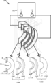
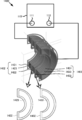
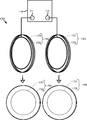
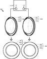
- the power supply coil and power supply resonator in the power supply module, and the power reception coil and power reception resonator in the power reception module have a crescent shape and a crescent shape as shown in FIG.
- Wireless power supply system using a cylindrical coil Akira to Specifically, a crescent-shaped cylindrical shape in which a power feeding resonator in a power feeding module and a power receiving resonator in a power receiving module are arranged to face each other and the whole inner circumferential surface of the power feeding resonator and the power receiving resonator are covered with the inner circumferential surface of the coil.
- a magnetic field space Z formed by the wireless power supply system in which the magnetic members are arranged will be described as a third embodiment by measuring the magnetic field strength and the like.
- the change in the transmission characteristic “S21” and the magnetic field when the aluminum piece 60 is inserted into the coil inner periphery of the power receiving resonator 1332 and when the aluminum piece 60 is not inserted Measure the change in intensity.
- the entire inner peripheral surfaces of the coils of the power feeding resonator 1422 and the power receiving resonator 1432 are covered in the power feeding module 1402 and the power receiving module 1403 shown in FIG.
- the magnetic field space Z formed by the wireless power supply system 1400 including the crescent-shaped cylindrical magnetic members 1423 and 1433 the aluminum piece 60 and the aluminum piece 60 are inserted into the inner periphery of the coil of the power receiving resonator 1432.
- the change of the transmission characteristic “S21” and the change of the magnetic field strength when not inserted are measured.
- a wireless power supply system 1300 used in the third comparative example includes a power supply module 1302 including a power supply coil 1321 having a crescent shape and a power supply resonator 1322 having a crescent-shaped cylindrical coil structure, and
- the power receiving module 1303 includes a power receiving coil 1331 having a crescent moon shape and a power receiving resonator 1332 having a crescent-shaped cylindrical coil structure.
- the power supply coil 1321 is connected to the output terminal 111 of the network analyzer 110
- the power receiving coil 1331 is connected to the input terminal 112 of the network analyzer 110.
- the power supply coil 1321 serves to supply the power obtained from the network analyzer 110 to the power supply resonator 1322 by electromagnetic induction.
- This power supply coil 1321 is formed by winding a copper wire (with an insulating coating) with a wire diameter of 1 mm ⁇ once, and as shown in FIG. 24, the diameter of the outer circle of the coil of the power supply coil 1321 is 60 mm, and the diameter of the inner circle is The crescent shape is 30mm.
- the power receiving coil 1331 plays a role of outputting electric power transmitted from the power feeding resonator 1322 to the power receiving resonator 1332 as magnetic field energy to the input terminal 112 of the network analyzer 110 by electromagnetic induction. Similar to the power feeding coil 1321, the power receiving coil 1331 is made by winding a copper wire (with an insulating coating) having a wire diameter of 1 mm ⁇ once, the diameter of the outer circle of the coil of the power receiving coil 1331 is 60 mm, and the diameter of the inner circle is 30 mm. It has a crescent moon shape.
- the power feeding resonator 1322 and the power receiving resonator 1332 are each an LC resonance circuit and play a role of creating a magnetic field resonance state.
- the power feeding resonator 1322 and the power receiving resonator 1332 are each formed by winding a copper wire (with an insulating coating) with a wire diameter of 1 mm ⁇ three times (the space between the wires is 0.1 mm), and the diameter of the outer circle of the coil is 60 mm. It has a crescent-shaped cylindrical coil structure with a circle diameter of 30 mm.
- the distance between the power feeding coil 1321 and the power feeding resonator 1322 is set to 10 mm
- the distance between the power feeding resonator 1322 and the power receiving resonator 1332 is set to 8 mm
- the power receiving resonator 1332 and the power receiving coil 1331 are The distance between is set to 10 mm.
- the power feeding resonator 1322 and the power receiving resonator 1332 have a resonance frequency of 15.5 MHz.
- the power feeding resonator 1322 and the power receiving resonator 1332 are arranged such that the coil surface of the power feeding resonator 1322 and the coil surface of the power receiving resonator 1332 face each other in parallel.
- the metal piece inserted on the inner peripheral side of the coil of the power receiving resonator 1332 receives the aluminum piece 60 made of aluminum having a rectangular parallelepiped shape having a thickness of 5 mm.
- a resonator 1332 having a shape conforming to the inner circumferential shape of the coil (a crescent shape) is used.
- the transmission characteristic “S 21” when the aluminum piece 60 is not inserted on the coil inner periphery side of the power receiving resonator 1332 is transmitted to the wireless power supply system 1300. Measure while changing the frequency of the supplied AC power.
- the measured waveform 1341 of the measured transmission characteristic “S21” has peaks separated on the low frequency side and the high frequency side.
- the power supply resonator 1322 and the power reception resonator 1332 are in resonance with the same phase.
- the direction of the current flowing through the power feeding resonator 1322 and the direction of the current flowing through the power receiving resonator 1332 are the same.
- the magnetic field strength distribution in this in-phase resonance mode is shown in FIG. From the magnetic field strength distribution of FIG. 26A, the magnetic field space Z1351 having a relatively small magnetic field strength can be confirmed on the outer peripheral side of the power feeding resonator 1322 and the power receiving resonator 1332 by reducing the influence of the magnetic field. .
- FIG. 26B shows the magnetic field strength distribution in this reversed phase resonance mode. From the magnetic field strength distribution of FIG. 26B, the magnetic field space Z1353 having a relatively small magnetic field strength can be confirmed on the inner peripheral side of the power feeding resonator 1322 and the power receiving resonator 1332 by reducing the influence of the magnetic field. it can.
- the transmission characteristic “S21” when the aluminum piece 60 is inserted on the inner circumference side of the coil of the power receiving resonator 1332 is changed while changing the frequency of the AC power supplied to the wireless power supply system 1300. taking measurement.
- the measurement result is shown in FIG. 25 as a measurement waveform 1342 of the transmission characteristic “S21” when the aluminum piece 60 is inserted on the inner circumference side of the coil of the power receiving resonator 1332.
- the transmission characteristic “S 21” at the frequency fL near the peak on the low frequency side is the measurement waveform 1341 of the transmission characteristic “S 21” when the aluminum piece 60 is not inserted on the coil inner periphery side of the power receiving resonator 1332.
- the transmission characteristic “S21” at the frequency fH near the peak on the high frequency side is also compared to the measured waveform 1341 of the transmission characteristic “S21” when the aluminum piece 60 is not inserted on the inner peripheral side of the coil of the power receiving resonator 1332. It turns out that it falls remarkably.
- FIG. 26C shows the magnetic field strength distribution in the in-phase resonance mode when the aluminum piece 60 is inserted on the inner circumference side of the coil of the power receiving resonator 1332.
- FIG. 26D shows the magnetic field strength distribution in the reverse phase resonance mode when the aluminum piece 60 is inserted on the inner circumference side of the coil of the power receiving resonator 1332.
- a wireless power supply system 1400 used in the third embodiment includes a crescent-shaped feeding coil 1421, a crescent-shaped cylindrical coil structure feeding resonator 1422, and a feeding resonator 1422 coil.
- the output terminal 111 of the network analyzer 110 is connected to the feeding coil 1421, and the input terminal 112 of the network analyzer 110 is connected to the power receiving coil 1431.
- the magnetic members 1423 and 1433 are formed of a resin in which magnetic powder is dispersed.
- the magnetic members 1423 and 1433 have a crescent-shaped cylindrical shape with a thickness of 1 mm along the inner peripheral surfaces of the power feeding resonator 1422 and the power receiving resonator 1432, and the magnetic permeability thereof is 100.
- Other configurations such as the power feeding coil 1421, the power feeding resonator 1422, the power receiving coil 1431, and the power receiving resonator 1432 are the same as those of the wireless power supply system 1300 according to the third comparative example.
- the transmission characteristic “S 21” when the aluminum piece 60 is not inserted on the coil inner periphery side of the power receiving resonator 1432 is transmitted to the wireless power supply system 1400. Measure while changing the frequency of the supplied AC power.
- the measured waveform 1441 of the measured transmission characteristic “S21” has peaks separated on the low frequency side and the high frequency side.
- FIG. 29A shows the magnetic field strength distribution when the frequency of the alternating current power supplied to the power supply module 1402 is set to the frequency fL near the peak on the low frequency side (common mode resonance mode).
- the magnetic field space Z11451 having a relatively small magnetic field strength can be confirmed on the outer peripheral side of the power feeding resonator 1422 and the power receiving resonator 1432 by reducing the influence of the magnetic field.
- a magnetic field space Z1452 having a magnetic field intensity slightly reduced by the influence of the magnetic field can be confirmed on the inner peripheral side of the power feeding resonator 1422 and the power receiving resonator 1432.
- a magnetic field space Z1452 having a smaller magnetic field strength than that of the third comparative example can be formed on the inner peripheral side of the power feeding resonator 1422 and the power receiving resonator 1432.
- FIG. 29B shows the magnetic field strength distribution when the frequency of AC power supplied to the power supply module 1402 is set to the frequency fH near the peak on the high frequency side (reverse phase resonance mode).
- the magnetic field space Z1453 having a relatively small magnetic field strength can be confirmed on the inner peripheral side of the power feeding resonator 1422 and the power receiving resonator 1432 by reducing the influence of the magnetic field. it can.
- the magnetic field space Z1453 having a smaller magnetic field strength than that of the third comparative example can be formed on the inner peripheral side of the power feeding resonator 1422 and the power receiving resonator 1432.
- the magnetic field space Z1453 formed in the anti-phase resonance mode can be formed wider than the magnetic field space Z1452 formed in the in-phase resonance mode.
- the transmission characteristic “S21” when the aluminum piece 60 is inserted on the inner circumference side of the coil of the power receiving resonator 1432 is changed while changing the frequency of the AC power supplied to the wireless power supply system 1400. taking measurement.
- the measurement result is shown in FIG. 28 as a measured waveform 1442 of the transmission characteristic “S21” when the aluminum piece 60 is inserted on the inner circumference side of the coil of the power receiving resonator 1432.
- the transmission characteristic “S21” at the frequency fL near the peak on the low frequency side is the measurement waveform 1441 of the transmission characteristic “S21” when the aluminum piece 60 is not inserted on the inner peripheral side of the coil of the power receiving resonator 1432. It can be seen that the value of the transmission characteristic is maintained at a high value, although it is slightly lower than that of.
- the transmission characteristic “S21” at the frequency fH near the peak on the high frequency side is almost the same as the measured waveform 1441 of the transmission characteristic “S21” when the aluminum piece 60 is not inserted on the inner peripheral side of the coil of the power receiving resonator 1432. It can be seen that the same value is maintained (see point P in FIG. 28).
- FIG. 29C shows the magnetic field strength distribution in the in-phase resonance mode when the aluminum piece 60 is inserted on the inner peripheral side of the coil of the power receiving resonator 1432.
- FIG. 29D shows the magnetic field strength distribution in the anti-phase resonance mode when the aluminum piece 60 is inserted on the inner peripheral side of the coil of the power receiving resonator 1432.
- the magnetic field strength distribution when the aluminum piece 60 is inserted on the inner circumference side of the coil of the power receiving resonator 1432 is an aluminum piece compared to the third comparative example. It can be seen that the influence of 60 is not so much.
- crescent-shaped and crescent-shaped cylindrical coils are used for the power supply coil and power supply resonator in the power supply module and the power reception coil and power reception resonator in the power reception module, and the inner peripheral surfaces of the power supply resonator and power reception resonator.
- the wireless power supply system 1400 when using a crescent-shaped cylindrical magnetic member extending along the line, when power is transmitted between the power supply module 1402 and the power reception module 1403, the power supply resonator 1422 and the power reception resonance
- the magnetic field generated around the resonator 1432 is blocked by the magnetic members 1423 and 1433, and the magnetic field space Z1453 larger than the magnetic field space Z1353 according to the third comparative example is formed on the inner peripheral side of the coils of the power feeding resonator 1422 and the power receiving resonator 1432. Can be formed. Further, it can be said that the influence of the magnetic field generated in the wireless power supply system 1400 is reduced on the aluminum piece 60.
- the power supply coil and the power supply resonator in the power supply module, the power reception coil and the power reception resonator in the power reception module have the same diameter set to 100 mm ⁇ .
- the power supply coil and power supply resonator in the power supply module and the power reception coil and power reception resonator in the power reception module have different coil diameters as shown in FIG. A wireless power supply system when using the above will be described. Specifically, the coil diameters of the power receiving coil and the power receiving resonator in the power receiving module are smaller than those of the power feeding coil and the power feeding resonator in the power feeding module.
- the power feeding resonator in the power feeding module and the power receiving resonator in the power receiving module are arranged to face each other, and a cylindrical magnetic member that covers the entire inner peripheral surface of the coil is arranged on the coil inner peripheral surface side of the power feeding resonator and the power receiving resonator.
- the magnetic field space Z formed by the wireless power supply system will be described as a fourth embodiment by measuring the magnetic field strength and the like.
- the change in the transmission characteristic “S21” is measured when the aluminum piece 60 is inserted into the coil inner periphery of the power receiving resonator 1532 and when the aluminum piece 60 is not inserted. To do.
- the entire inner peripheral surfaces of the coils of the power feeding resonator 1622 and the power receiving resonator 1632 are covered in the power feeding module 1602 and the power receiving module 1603 shown in FIG.
- the magnetic field space Z formed by the wireless power supply system 1600 including the cylindrical magnetic members 1623 and 1633 when the aluminum piece 60 is inserted into the coil inner peripheral side of the power receiving resonator 1632, the aluminum piece 60 is inserted.
- the change of the transmission characteristic “S21” when there is not and the magnetic field strength when the aluminum piece 60 is not inserted are measured.
- three models model A1, model A2, model A3: details will be described later
- the diameter of the cylindrical magnetic member 1623 covering the entire inner peripheral surface of the coil of the power feeding resonator 1622 are changed. Use to measure.
- the wireless power supply system 1500 used in the fourth comparative example has a circular power supply coil 1521 including a circular power supply coil 1521, a cylindrical power supply resonator 1522, and a circular shape.
- a power receiving module 1503 including a power receiving coil 1531 and a cylindrical power receiving resonator 1532 is provided.
- the power supply coil 1521 is connected to the output terminal 111 of the network analyzer 110
- the power receiving coil 1531 is connected to the input terminal 112 of the network analyzer 110.
- the power supply coil 1521 serves to supply the power obtained from the network analyzer 110 to the power supply resonator 1522 by electromagnetic induction.
- This power supply coil 1521 is formed in a circular shape with an inner diameter of 54 mm ⁇ by winding a copper wire (with an insulating coating) having a diameter of 1 mm ⁇ once.
- the power receiving coil 1531 plays a role of outputting electric power transmitted from the power feeding resonator 1522 to the power receiving resonator 1532 as magnetic field energy to the input terminal 112 of the network analyzer 110 by electromagnetic induction.
- the power receiving coil 1531 has a circular shape with an inner diameter of 36 mm ⁇ by winding a copper wire (with an insulating coating) having a diameter of 1 mm ⁇ once.
- the power feeding resonator 1522 and the power receiving resonator 1532 are each an LC resonance circuit and play a role of creating a magnetic field resonance state.
- the power feeding resonator 1522 is a solenoid type coil having an inner diameter of 54 mm ⁇ , in which a copper wire (with an insulating coating) having a diameter of 1 mm ⁇ is wound four times, and has a resonance frequency of 17.2 MHz.
- the power receiving resonator 1532 is a solenoid type coil having a coil inner diameter of 36 mm ⁇ , which is a six-turn winding of a copper wire (with an insulating coating) having a wire diameter of 1 mm ⁇ , and has a resonance frequency of 17.2 MHz.
- the distance between the power feeding coil 1521 and the power feeding resonator 1522 is set to 5 mm
- the distance between the power feeding resonator 1522 and the power receiving resonator 1532 is set to 18 mm
- the power receiving resonator 1532 and the power receiving coil 1531 are The distance between is set to 5 mm.
- the power feeding resonator 1522 and the power receiving resonator 1532 are arranged so that the coil surface of the power feeding resonator 1522 and the coil surface of the power receiving resonator 1532 face each other in parallel.
- the metal piece to be inserted on the coil inner circumference side of the power receiving resonator 1532 includes a columnar aluminum piece 60 having a diameter of 27 mm and a thickness of 10 mm. Is used.
- the transmission characteristic “S ⁇ b> 21” when the aluminum piece 60 is not inserted on the coil inner periphery side of the power receiving resonator 1532 is transmitted to the wireless power supply system 1500. Measure while changing the frequency of the supplied AC power.
- the measured waveform 1541 of the measured transmission characteristic “S21” has peaks separated on the low frequency side and the high frequency side.
- the transmission characteristic “S21” when the aluminum piece 60 is inserted on the inner circumference side of the coil of the power receiving resonator 1532 is changed while changing the frequency of the AC power supplied to the wireless power supply system 1500. taking measurement.
- the measurement result is shown in FIG. 31 as a measurement waveform 1542 of the transmission characteristic “S21” when the aluminum piece 60 is inserted on the inner circumference side of the coil of the power receiving resonator 1532.
- this measurement waveform 1542 the transmission characteristic “S 21” at the frequency fL near the peak on the low frequency side and the transmission characteristic “S 21” at the frequency fH near the peak on the high frequency side are on the inner circumference side of the coil of the power receiving resonator 1532. It can be seen that this is significantly lower than the measured waveform 1541 of the transmission characteristic “S21” when the aluminum piece 60 is not inserted.
- a wireless power supply system 1600 used in the fourth embodiment includes a circular feeding coil 1621, a cylindrical feeding resonator 1622, and the entire inner peripheral surface of the feeding resonator 1622.
- a power receiving module 1603 including a magnetic member 1633.
- the output terminal 111 of the network analyzer 110 is connected to the feeding coil 1621, and the input terminal 112 of the network analyzer 110 is connected to the power receiving coil 1631.
- the magnetic members 1623 and 1633 are made of a resin in which magnetic powder is dispersed.
- the magnetic member 1623 has a cylindrical shape with an inner diameter of 46 mm ⁇ and a thickness of 1 mm, and its magnetic permeability is 100.
- the magnetic member 1623 has a cylindrical shape with an inner diameter of 37 mm ⁇ and a thickness of 1 mm, and its magnetic permeability is 100.
- the magnetic member 1623 has a cylindrical shape with an inner diameter of 28 mm ⁇ and a thickness of 1 mm, and its permeability is 100.
- the inner diameter of the magnetic member 1633 in the models A1, A2 and A3 is a common cylindrical shape of 28 mm ⁇ and 1 mm in thickness, and the magnetic permeability is 100.
- Other configurations such as the power feeding coil 1621, the power feeding resonator 1622, the power receiving coil 1631, and the power receiving resonator 1632 are the same as those of the wireless power supply system 1500 according to the fourth comparative example.
- the transmission characteristic “S ⁇ b> 21” when the aluminum piece 60 is not inserted on the inner circumference side of the coil of the power receiving resonator 1632 is transmitted to the wireless power supply system 1600. Measure while changing the frequency of the supplied AC power.
- the measured waveform 1641A1 of the measured transmission characteristic “S21” has peaks separated on the low frequency side and the high frequency side.
- the magnetic field strength distribution when the frequency of the AC power supplied to the power supply module 1602 is set to the frequency fH near the peak on the high frequency side is shown in the model A1 of FIG. From this magnetic field strength distribution, the magnetic field space ZA1 having a relatively small magnetic field strength can be confirmed on the inner peripheral side of the power feeding resonator 1622 and the power receiving resonator 1632 by reducing the influence of the magnetic field. Thus, in the antiphase resonance mode, the magnetic field space ZA1 having a small magnetic field strength can be formed on the inner peripheral side of the power feeding resonator 1622 and the power receiving resonator 1632.
- the measured waveform 1641A2 of the measured transmission characteristic “S21” has peaks separated on the low frequency side and the high frequency side.
- the magnetic field strength distribution when the frequency of the AC power supplied to the power supply module 1602 is set to the frequency fH near the peak on the high frequency side (reverse phase resonance mode) is shown in the model A2 of FIG. From this magnetic field strength distribution, the magnetic field space ZA2 having a relatively small magnetic field strength can be confirmed on the inner peripheral side of the power feeding resonator 1622 and the power receiving resonator 1632 in the same manner as the model A1. .
- the magnetic field strength similar to that of the model A1 is provided on the inner peripheral side of the power feeding resonator 1622 and the power receiving resonator 1632.
- the magnetic field space ZA2 can be formed.
- the peak of the measured waveform 1641A3 of the measured transmission characteristic “S21” is separated into the low frequency side and the high frequency side.
- the magnetic field strength distribution when the frequency of the AC power supplied to the power supply module 1602 is set to the frequency fH near the peak on the high frequency side (reverse phase resonance mode) is shown in the model A3 of FIG. From this magnetic field strength distribution, the magnetic field space ZA3 having a relatively small magnetic field strength is confirmed on the inner peripheral side of the feeding resonator 1622 and the power receiving resonator 1632 as in the models A1 and A2. be able to.
- model A1 and model A2 are arranged on the inner peripheral side of power feeding resonator 1622 and power receiving resonator 1632.
- a magnetic field space ZA3 having a similar magnetic field strength can be formed.
- the transmission characteristic “S21” when the aluminum piece 60 is inserted on the inner peripheral side of the coil of the power receiving resonator 1632 is changed. taking measurement.
- the measurement result of model A1 is shown in FIG. 33 as a measurement waveform 1642A1 of the transmission characteristic “S21” when the aluminum piece 60 is inserted on the inner circumference side of the coil of the power receiving resonator 1632.
- the transmission characteristic “S21” at the frequency fL near the peak on the low frequency side is the measured waveform 1641A1 of the transmission characteristic “S21” when the aluminum piece 60 is not inserted on the inner peripheral side of the coil of the power receiving resonator 1632. It can be seen that the value of the transmission characteristic is maintained at a high value, although it is slightly lower than that of.
- the transmission characteristic “S21” at the frequency fH near the peak on the high frequency side is almost the same as the measured waveform 1641A1 of the transmission characteristic “S21” when the aluminum piece 60 is not inserted on the inner peripheral side of the coil of the power receiving resonator 1632. It can be seen that the same value is maintained (see point P of model A1 in FIG. 33).
- the measurement result of the model A2 is shown in FIG. 33 as a measurement waveform 1642A2 of the transmission characteristic “S21” when the aluminum piece 60 is inserted on the inner peripheral side of the coil of the power receiving resonator 1632.
- the transmission characteristic “S21” at the frequency fL near the peak on the low frequency side is the measured waveform 1641A2 of the transmission characteristic “S21” when the aluminum piece 60 is not inserted on the inner peripheral side of the coil of the power receiving resonator 1632. It can be seen that the value of the transmission characteristic is maintained at a high value, although it is slightly lower than that of.
- the transmission characteristic “S21” at the frequency fH near the peak on the high frequency side is almost the same as the measured waveform 1641A2 of the transmission characteristic “S21” when the aluminum piece 60 is not inserted on the inner peripheral side of the coil of the power receiving resonator 1632. It can be seen that the same value is maintained (see point P of model A2 in FIG. 33).
- the measurement result of the model A3 is shown in FIG. 33 as a measurement waveform 1642A3 of the transmission characteristic “S21” when the aluminum piece 60 is inserted on the inner peripheral side of the coil of the power receiving resonator 1632.
- the transmission characteristic “S21” at the frequency fL near the peak on the low frequency side is the measurement waveform 1641A3 of the transmission characteristic “S21” when the aluminum piece 60 is not inserted on the inner peripheral side of the coil of the power receiving resonator 1632. It can be seen that the value of the transmission characteristic is maintained at a high value, although it is slightly lower than that of.
- the transmission characteristic “S21” at the frequency fH near the peak on the high frequency side is almost the same as the measured waveform 1641A3 of the transmission characteristic “S21” when the aluminum piece 60 is not inserted on the inner peripheral side of the coil of the power receiving resonator 1632. It can be seen that the same value is maintained (see point P of model A3 in FIG. 33).
- the magnetic members 1623 and 1633 having a thickness of 1 mm are used.
- the magnetic members 1623 and 1633 Regarding the magnetic field space Z formed by the wireless power supply system 1600 when the thickness is increased to 2 mm, when the aluminum piece 60 is inserted on the coil inner peripheral side of the power receiving resonator 1632 and when the aluminum piece 60 is not inserted
- the change of the transmission characteristic “S21” is measured. Note that a model A1-2 in which the thickness of the magnetic members 1623 and 1633 of the model A1 of the fourth embodiment is changed from 1 mm to 2 mm will be described.
- a model A2-2 is obtained by changing the thickness of the magnetic members 1623 and 1633 of the model A2 of the fourth embodiment from 1 mm to 2 mm, and the thickness of the magnetic members 1623 and 1633 of the model A3 of the fourth embodiment is 1 mm.
- a model that is changed from 2 mm to 2 mm will be described as a model A3-2.
- Other configurations are the same as those of the wireless power supply system 1600 of the fourth embodiment.
- the measurement result of the transmission characteristic “S21” when the aluminum piece 60 is inserted on the inner peripheral side of the coil of the power receiving resonator 1632 is shown as a measurement waveform 1642A1-2 in FIG.
- the transmission characteristic “S21” at the frequency fH near the peak on the high frequency side is the measurement waveform of the transmission characteristic “S21” when the aluminum piece 60 is not inserted into the inner peripheral side of the coil of the power receiving resonator 1632. It can be seen that substantially the same value is maintained as compared with 1641A1-2 (see point P1 of model A1-2 in FIG. 34).
- the transmission characteristic “S21” at the frequency fL near the peak on the low frequency side is also compared with the measured waveform 1641A1-2 of the transmission characteristic “S21” when the aluminum piece 60 is not inserted on the inner peripheral side of the coil of the power receiving resonator 1632.
- substantially the same value is maintained (see point P2 of model A1-2 in FIG. 34).
- the measured waveform 1641A2-2 of the measured transmission characteristic “S21” also in the model A2-2.
- the peak is separated into the low frequency side and the high frequency side.
- the measurement result of the transmission characteristic “S21” when the aluminum piece 60 is inserted on the inner peripheral side of the coil of the power receiving resonator 1632 is shown as a measurement waveform 1642A2-2 in FIG.
- the transmission characteristic “S21” at the frequency fH near the peak on the high frequency side is the measurement waveform of the transmission characteristic “S21” when the aluminum piece 60 is not inserted into the inner peripheral side of the coil of the power receiving resonator 1632. It can be seen that substantially the same value is maintained as compared with 1641A2-2 (see point P1 of model A2-2 in FIG. 34).
- the transmission characteristic “S21” at the frequency fL near the peak on the low frequency side is also compared with the measured waveform 1641A2-2 of the transmission characteristic “S21” when the aluminum piece 60 is not inserted on the inner peripheral side of the coil of the power receiving resonator 1632.
- substantially the same value is maintained (see point P2 of model A2-2 in FIG. 34).
- the measured waveform 1641A3-2 of the measured transmission characteristic “S21” also in the model A3-2.
- the peak is separated into the low frequency side and the high frequency side.
- model A3-2 the measurement result of the transmission characteristic “S21” when the aluminum piece 60 is inserted on the inner circumference side of the coil of the power receiving resonator 1632 is shown as a measurement waveform 1642A3-2 in FIG.
- the transmission characteristic “S21” at the frequency fH near the peak on the high frequency side is the measurement waveform of the transmission characteristic “S21” when the aluminum piece 60 is not inserted on the coil inner periphery side of the power receiving resonator 1632. It can be seen that substantially the same value is maintained as compared to 1641A3-2 (see point P1 of model A3-2 in FIG. 34).
- the transmission characteristic “S21” at the frequency fL near the peak on the low frequency side is also compared with the measured waveform 1641A3-2 of the transmission characteristic “S21” when the aluminum piece 60 is not inserted on the inner peripheral side of the coil of the power receiving resonator 1632.
- substantially the same value is maintained (see point P2 of model A3-2 in FIG. 34).
- the distance A between the power feeding coil 21 and the power feeding resonator 22 is set to 15 mm
- the distance B between the power receiving coil 31 and the power receiving resonator 32 is set to 15 mm
- the distance C between the power feeding resonator 22 and the power receiving resonator 32 is set to 30 mm
- the distance A between the power feeding coil and the power feeding resonator is set to 15 mm
- the power feeding coil is disposed on the inner peripheral side of the power feeding resonator, and the power receiving coil is disposed on the inner peripheral side of the power receiving resonator.
- the wireless power supply system in the case of having been performed will be described. Specifically, a power feeding coil is arranged on the inner circumference side of the power feeding resonator, and a cylindrical magnetic member is arranged on the inner circumference side of the power feeding coil, and power is received on the inner circumference side of the power receiving resonator.
- the magnetic field space Z formed by the wireless power supply system including the coil and the power receiving module having the cylindrical magnetic member disposed on the inner peripheral side of the power receiving coil is measured by measuring the magnetic field strength and the like. This will be described as an example.
- the change in the transmission characteristic “S21” and the magnetic field when the aluminum piece 60 is inserted into the coil inner periphery of the power receiving resonator 1732 and when the aluminum piece 60 is not inserted Measure the change in intensity.
- the entire inner peripheral surfaces of the coils of the power feeding resonator 1822 and the power receiving resonator 1832 are covered in the power feeding module 1802 and the power receiving module 1803 shown in FIG.
- the aluminum piece 60 is inserted when the aluminum piece 60 is inserted into the inner peripheral side of the coil of the power receiving resonator 1832. Measure the change in the transmission characteristic “S21” and the change in the magnetic field strength when there is not.
- the wireless power supply system 1700 used in the fifth comparative example has a power supply module 1702 in which a power supply coil 1721 is arranged on the inner peripheral side of the power supply resonator 1722 and an inner peripheral side of the power reception resonator 1732.
- the power supply coil 1721 is connected to the output terminal 111 of the network analyzer 110
- the power receiving coil 1731 is connected to the input terminal 112 of the network analyzer 110.
- the feeding coil 1721 serves to supply the power obtained from the network analyzer 110 to the feeding resonator 1722 by electromagnetic induction.
- the power supply coil 1721 is formed in a circular shape having an inner diameter of 70 mm ⁇ by winding a copper wire (with an insulating coating) having a diameter of 1 mm ⁇ once.
- the power receiving coil 1731 plays a role of outputting electric power transmitted from the power feeding resonator 1722 to the power receiving resonator 1732 as magnetic field energy to the input terminal 112 of the network analyzer 110 by electromagnetic induction.
- the power receiving coil 1731 is formed by winding a copper wire (with an insulating coating) having a wire diameter of 1 mm ⁇ once and forming a circular shape having an inner diameter of 70 mm ⁇ .
- the power feeding resonator 1722 and the power receiving resonator 1732 are each an LC resonance circuit and play a role of creating a magnetic field resonance state.
- the power feeding resonator 1722 and the power receiving resonator 1732 are solenoid type coils each having a coil inner diameter of 100 mm ⁇ , each of which has a resonance frequency of 12.9 MHz.
- the distance between the power supply resonator 1722 and the power reception resonator 1732 is set to 30 mm.
- the metal piece to be inserted on the coil inner peripheral side of the power receiving resonator 1732 includes a columnar aluminum piece 60 having a diameter of 58 mm and a thickness of 20 mm. Is used.
- the transmission characteristic “S ⁇ b> 21” when the aluminum piece 60 is not inserted on the coil inner periphery side of the power receiving resonator 1732 is transmitted to the wireless power supply system 1700. Measure while changing the frequency of the supplied AC power.
- the measured waveform 1741 of the measured transmission characteristic “S21” has peaks separated on the low frequency side and the high frequency side.
- FIG. 37A shows the magnetic field strength distribution in this in-phase resonance mode. From the magnetic field strength distribution in FIG. 37A, the magnetic field space Z1751 having a relatively small magnetic field strength can be confirmed on the outer peripheral side of the power feeding resonator 1722 and the power receiving resonator 1732 by reducing the influence of the magnetic field. .
- FIG. 37B shows the magnetic field strength distribution in the reverse phase resonance mode. From the magnetic field strength distribution of FIG. 37 (B), the magnetic field space Z1753 having a relatively small magnetic field strength can be confirmed on the inner peripheral side of the power feeding resonator 1722 and the power receiving resonator 1732 by reducing the influence of the magnetic field. it can.
- the transmission characteristic “S21” when the aluminum piece 60 is inserted on the inner circumference side of the coil of the power receiving resonator 1732 is changed. taking measurement.
- the measurement result is shown in FIG. 36 as a measurement waveform 1742 of the transmission characteristic “S21” when the aluminum piece 60 is inserted on the inner circumference side of the coil of the power receiving resonator 1732.
- the transmission characteristic “S21” at the frequency fL near the peak on the low frequency side is the measurement waveform 1741 of the transmission characteristic “S21” when the aluminum piece 60 is not inserted on the inner peripheral side of the coil of the power receiving resonator 1732.
- the transmission characteristic “S21” at the frequency fH near the peak on the high frequency side is also compared with the measured waveform 1741 of the transmission characteristic “S21” when the aluminum piece 60 is not inserted on the inner peripheral side of the coil of the power receiving resonator 1732. It turns out that it falls remarkably.
- FIG. 37C shows the magnetic field strength distribution in the in-phase resonance mode when the aluminum piece 60 is inserted on the inner circumference side of the coil of the power receiving resonator 1732.
- FIG. 37D shows the magnetic field strength distribution in the anti-phase resonance mode when the aluminum piece 60 is inserted on the inner peripheral side of the coil of the power receiving resonator 1732.
- the wireless power supply system 1800 used in the fifth embodiment has a power supply coil 1821 arranged on the inner peripheral side of the power supply resonator 1822, and further, a cylindrical magnet on the inner peripheral side of the power supply coil 1821.
- the power supply module 1802 in which the member 1823 is disposed, and the power reception module 1803 in which the power reception coil 1831 is disposed on the inner peripheral side of the power reception resonator 1832 and the cylindrical magnetic member 1833 is disposed on the inner peripheral side of the power reception coil 1831.
- the output terminal 111 of the network analyzer 110 is connected to the feeding coil 1821, and the input terminal 112 of the network analyzer 110 is connected to the power receiving coil 1831.
- the magnetic members 1823 and 1833 are made of a resin in which magnetic powder is dispersed.
- the magnetic members 1823 and 1833 have a cylindrical shape with an inner diameter of 60 mm ⁇ , a height of 30 mm, and a thickness of 1 mm.
- the magnetic permeability is 100.
- Other configurations such as the power feeding coil 1821, the power feeding resonator 1822, the power receiving coil 1831, and the power receiving resonator 1832 are the same as those of the wireless power supply system 1700 according to the fifth comparative example.
- the transmission characteristic “S ⁇ b> 21” when the aluminum piece 60 is not inserted on the inner peripheral side of the coil of the power receiving resonator 1832 is transmitted to the wireless power supply system 1800. Measure while changing the frequency of the supplied AC power.
- the measured waveform 1841 of the measured transmission characteristic “S21” has peaks separated on the low frequency side and the high frequency side.
- FIG. 40A shows the magnetic field strength distribution when the frequency of the alternating current power supplied to the power supply module 1802 is set to the frequency fL near the peak on the low frequency side (common mode resonance mode).
- the magnetic field space Z1851 having a relatively small magnetic field strength can be confirmed on the outer peripheral side of the power feeding resonator 1822 and the power receiving resonator 1832 by reducing the influence of the magnetic field.
- a magnetic field space Z1852 having a magnetic field intensity slightly reduced by the magnetic field can be confirmed on the inner peripheral side of the power feeding resonator 1822 and the power receiving resonator 1832.
- a magnetic field space Z1852 having a smaller magnetic field strength than that of the fifth comparative example can be formed on the inner peripheral side of the power feeding resonator 1822 and the power receiving resonator 1832.
- FIG. 40B shows the magnetic field intensity distribution when the frequency of AC power supplied to the power supply module 1802 is set to the frequency fH near the peak on the high frequency side (reverse phase resonance mode).
- the magnetic field space Z1853 having a relatively small magnetic field strength can be confirmed on the inner peripheral side of the feeding resonator 1822 and the power receiving resonator 1832 by reducing the influence of the magnetic field. it can.
- the magnetic field space Z1853 having a smaller magnetic field strength than that of the fifth comparative example can be formed on the inner peripheral side of the power feeding resonator 1822 and the power receiving resonator 1832.
- the magnetic field space Z1853 formed in the antiphase resonance mode can be formed wider than the magnetic field space Z1852 formed in the inphase resonance mode.
- the transmission characteristic “S21” when the aluminum piece 60 is inserted on the coil inner circumference side of the power receiving resonator 1832 (more specifically, the inner circumference side of the magnetic member 1833) Measurement is performed while changing the frequency of the AC power supplied to the supply system 1800.
- the measurement result is shown in FIG. 39 as a measurement waveform 1842 of the transmission characteristic “S21” when the aluminum piece 60 is inserted on the inner circumference side of the coil of the power receiving resonator 1832.
- the transmission characteristic “S21” at the frequency fL near the peak on the low frequency side is the measurement waveform 1841 of the transmission characteristic “S21” when the aluminum piece 60 is not inserted on the inner peripheral side of the coil of the power receiving resonator 1832. It can be seen that the value of the transmission characteristic is maintained at a high value, although it is slightly lower than that of.
- the transmission characteristic “S21” at the frequency fH near the peak on the high frequency side is almost the same as the measured waveform 1841 of the transmission characteristic “S21” when the aluminum piece 60 is not inserted on the inner peripheral side of the coil of the power receiving resonator 1832. It can be seen that the same value is maintained (see point P in FIG. 39).
- FIG. 40C shows the magnetic field strength distribution in the in-phase resonance mode when the aluminum piece 60 is inserted on the inner peripheral side of the coil of the power receiving resonator 1832.
- FIG. 40D shows the magnetic field intensity distribution in the anti-phase resonance mode when the aluminum piece 60 is inserted on the inner circumference side of the coil of the power receiving resonator 1832.
- the magnetic field strength distribution when the aluminum piece 60 is inserted on the inner circumference side of the coil of the power receiving resonator 1832 is an aluminum piece compared to the fifth comparative example. It can be seen that the influence of 60 is not so much.
- a power feeding coil is arranged on the inner peripheral side of the power feeding resonator, a power feeding module in which a cylindrical magnetic member is arranged on the inner peripheral side of the power feeding coil, and a power receiving coil is arranged on the inner peripheral side of the power receiving resonator.
- the wireless power supply system 1800 including a power receiving module in which a cylindrical magnetic member is arranged on the inner peripheral side of the power receiving coil
- the magnetic field generated around the power feeding resonator 1822 and the power receiving resonator 1832 is blocked by the magnetic members 1823 and 1833, and the magnetic field space according to the fifth comparative example is provided on the inner peripheral side of the coils of the power feeding resonator 1822 and the power receiving resonator 1832.
- a magnetic field space Z1853 larger than Z1753 can be formed.
- it can be said that the influence of the magnetic field generated in the wireless power supply system 1800 is reduced for the aluminum piece 60.
- the power supply coil 1821 is disposed on the inner peripheral side of the power supply resonator 1822, and the magnetic member 1823 is disposed on the inner peripheral side of the power supply coil 1821. Therefore, the power supply module 1802 has a symmetrical shape with respect to the central cross section. For this reason, even if the power receiving module 1803 is placed on either side of the power supply module 1802 (when other conditions such as the distance are the same), the power supply resonator 1822 included in the power supply module 1802 and the power reception included in the power reception module 1803 A magnetic field resonance state is created with the resonator 1832 under the same conditions, and wireless power transmission is possible.
- the power supply module 1802 used in the wireless power supply system 1800 may have a configuration in which the power supply coil 1821 is disposed on the outer peripheral side of the power supply resonator 1822, and in this case, the magnetic member 1823 is disposed on the inner periphery of the power supply resonator 1822. Will be placed on the side.
- the power receiving module 1803 may have a configuration in which the power receiving coil 1831 is disposed on the outer peripheral side of the power receiving resonator 1832.
- the magnetic member 1833 is disposed on the inner peripheral side of the power receiving resonator 1832.
- a wireless power supply system 1900 in the case where they are arranged will be described.
- the wireless power supply system 1900 has the same configuration as that of the wireless power supply system 400 according to the third embodiment of the first embodiment, and the coil central axis 1927 of the power feeding resonator 1922 and the coil central axis 1937 of the power receiving resonator 1932. Is different in that they are arranged so that they are misaligned.
- the wireless power supply system 1900 used in the sixth embodiment includes a power supply coil 1921, a power supply resonator 1922, and coil inner peripheral surfaces of the power supply coil 1921 and the power supply resonator 1922 as shown in the cross-sectional view of FIG.
- a cylindrical magnetic member 1923 that covers the whole a cylindrical magnetic member 1924 that covers the entire coil outer peripheral surface of the feeding coil 1921 and the feeding resonator 1922, and a ring shape that covers the side surface opposite to the coil facing surface of the feeding resonator 1922.
- a power supply module 1902 including the magnetic member 1925, a power receiving coil 1931, a power receiving resonator 1932, a cylindrical magnetic member 1933 covering the entire inner peripheral surface of the power receiving coil 1931 and the power receiving resonator 1932, a power receiving coil 1931, and a power receiving resonator.
- a receiving module 1903 comprises a magnetic member 1935 of a ring shape covering the side surface opposite to the Le facing surface.
- the power supply coil 1921 is connected to the output terminal 111 of the network analyzer 110, and the power receiving coil 1931 is connected to the input terminal 112 of the network analyzer 110.
- model A in which the positional deviation between the coil central axis 1927 of the power feeding resonator 1922 and the coil central axis 1937 of the power receiving resonator 1932 is set to 5 mm, and model B is set to 10 mm; Measurements are made using three models, Model C, set to 20 mm.
- the transmission characteristic “S ⁇ b> 21” when the aluminum piece 60 is not inserted on the coil inner periphery side of the power receiving resonator 1932 is transmitted to the wireless power supply system 1900. Measure while changing the frequency of the supplied AC power.
- the measured waveform 1941A of the transmission characteristic “S21” has peaks separated on the low frequency side and the high frequency side.
- the transmission characteristic “S21” when the aluminum piece 60 is inserted on the inner circumference side of the coil of the power receiving resonator 1932 is the frequency of AC power supplied to the wireless power supply system 1900. Measure while changing.
- the measurement result of Model A is shown in FIG. 41 as a measurement waveform 1942A of the transmission characteristic “S21” when the aluminum piece 60 is inserted on the inner circumference side of the coil of the power receiving resonator 1932.
- the transmission characteristic “S21” at the frequency fL near the peak on the low frequency side is the measurement waveform 1941A of the transmission characteristic “S21” when the aluminum piece 60 is not inserted on the inner peripheral side of the coil of the power receiving resonator 1932. It can be seen that the value of the transmission characteristic is maintained at a high value, although it is slightly lower than that of.
- the transmission characteristic “S21” at the frequency fH near the peak on the high frequency side is almost the same as the measured waveform 1941A of the transmission characteristic “S21” when the aluminum piece 60 is not inserted on the inner peripheral side of the coil of the power receiving resonator 1932. It can be seen that the same value is maintained (see point P of model A in FIG. 41).
- the transmission characteristic “S21” when the aluminum piece 60 is inserted on the inner peripheral side of the coil of the power receiving resonator 1932 is the frequency of AC power supplied to the wireless power supply system 1900. Measure while changing.
- the measurement result of Model B is shown in FIG. 41 as a measurement waveform 1942B of the transmission characteristic “S21” when the aluminum piece 60 is inserted on the inner circumference side of the coil of the power receiving resonator 1932.
- the transmission characteristic “S21” at the frequency fL near the peak on the low frequency side is the measurement waveform 1941B of the transmission characteristic “S21” when the aluminum piece 60 is not inserted on the inner peripheral side of the coil of the power receiving resonator 1932. It can be seen that the value of the transmission characteristic is maintained at a high value, although it is slightly lower than that of.
- the transmission characteristic “S21” at the frequency fH near the peak on the high frequency side is almost the same as the measured waveform 1941B of the transmission characteristic “S21” when the aluminum piece 60 is not inserted on the inner peripheral side of the coil of the power receiving resonator 1932. It can be seen that the same value is maintained (see point P of model B in FIG. 41).
- the transmission characteristic “S21” when the aluminum piece 60 is inserted on the inner circumference side of the coil of the power receiving resonator 1932 is the frequency of the AC power supplied to the wireless power supply system 1900. Measure while changing.
- the measurement result of Model C is shown in FIG. 41 as a measurement waveform 1942C of the transmission characteristic “S21” when the aluminum piece 60 is inserted on the inner circumference side of the coil of the power receiving resonator 1932.
- the transmission characteristic “S21” at the frequency fL near the peak on the low frequency side is the measurement waveform 1941C of the transmission characteristic “S21” when the aluminum piece 60 is not inserted on the inner peripheral side of the coil of the power receiving resonator 1932. It can be seen that the value of the transmission characteristic is maintained at a high value, although it is slightly lower than that of.
- the transmission characteristic “S21” at the frequency fH near the peak on the high frequency side is almost the same as the measured waveform 1941C of the transmission characteristic “S21” when the aluminum piece 60 is not inserted on the inner peripheral side of the coil of the power receiving resonator 1932. It can be seen that the same value is maintained (see point P of model C in FIG. 41).
- the positional deviation between the coil central axis 1927 of the power feeding resonator 1922 and the coil central axis 1937 of the power receiving resonator 1932 is set to 5 mm, the model B set to 10 mm, and the model B set to 20 mm.
- the transmission characteristic “S21” at the frequency fH near the peak on the high frequency side is the transmission characteristic “S21” when the aluminum piece 60 is not inserted on the inner peripheral side of the coil of the power receiving resonator 1932. It can be seen that substantially the same values are maintained as compared with the measurement waveforms 1941A, 1941B, and 1941C, respectively.
- the power feeding resonator 1922 and the power receiving resonator 1932 are relatively close to the inner peripheral side.
- a magnetic field space having a small magnetic field strength can be formed.
- the power supply module 202 including the power supply coil 21 and the power supply resonator 22 and the power reception module 203 including the power reception coil 31 and the power reception resonator 32 are main components, and the power supply resonator 22 and A solenoid type coil is used for the power receiving resonator 32, and the power feeding resonator 22 and the power receiving resonator 32 are arranged such that the coil surface of the power feeding resonator 22 and the coil surface of the power receiving resonator 32 face each other.
- a cylindrical magnetic member 23 that covers the entire coil inner peripheral surface of the power supply resonator 22 is disposed on the coil inner peripheral surface side of the power supply resonator 22.
- a cylindrical magnetic member 33 that covers the entire coil inner peripheral surface of the power receiving resonator 32 is also disposed on the coil inner peripheral surface side of the power receiving resonator 32.
- an AC power source via an oscillation circuit that adjusts the frequency of power supplied to the power supply module 202 is connected to the power supply coil 21 of the power supply module 202.
- a rechargeable battery via a rectification / stabilization circuit that rectifies received AC power and a charging circuit that prevents overcharge is connected to the power receiving coil 31 of the power receiving module 203.
- the oscillation circuit is housed in the inner peripheral side of the power supply resonator 22 on the power supply module 202 side (the inner peripheral side of the magnetic member 23), that is, the place where the magnetic field space Z253 is formed, and the power reception resonance on the power reception module 203 side.
- the rectification / stabilization circuit is housed in the inner peripheral side of the container 32 (inner peripheral side of the magnetic member 33), that is, in the place where the magnetic field space Z253 is formed.
- the charging circuit and the rechargeable battery may be housed inside the power receiving resonator 32 of the power receiving module 203.
- AC power supplied from the AC power source to the power supply coil 21 via the oscillation circuit is converted into electromagnetic induction and power supply resonance between the power supply coil 21 and the power supply resonator 22.
- a rectification / stabilization circuit and a charging circuit Supplied to the rechargeable battery.
- the magnetic field space Z253 having a relatively small magnetic field strength is formed in which the influence of the magnetic field on the oscillation circuit and the rectification / stabilization circuit arranged on the inner peripheral side of the power feeding resonator 22 and the power receiving resonator 32 is reduced. be able to.
- an oscillation circuit and a rectification / stabilization circuit for reducing the influence of the magnetic field in or near the magnetic field space Z253 formed on the inner peripheral side of the power feeding resonator 22 and the power receiving resonator 32. Therefore, the oscillation circuit and the rectification / stabilization circuit can be reduced / prevented from generating eddy currents due to the magnetic field, and adverse effects due to heat generation can be suppressed.
- the oscillation circuit and the rectification / stabilization circuit can be reduced in size while preventing heat generation. Become.
- the magnetic field space Z251, the magnetic field space Z252, and the magnetic field space Z253 are formed between the power feeding resonator 22 and the power receiving resonator 32, as shown in FIG. Even if a metal foreign object exists in the place, the magnetic field is not affected by the metal foreign object, and power can be supplied from the power supply module 202 to the power receiving module 203 efficiently and safely using the resonance phenomenon.
- the magnetic members 23 and 33, the magnetic members 24 and 34, and the magnetic members 25 and 35 are provided in both the power supply module 202 and the power reception module 203.
- a configuration in which only one of the modules 203 is arranged may be adopted.
- the wireless power supply system 2000 includes a power transmission sheet 2006 in which a plurality of power supply modules 2002 including a power supply coil 2021, a power supply resonator 2022, and a magnetic member 2023 are arranged, and a power reception module 2003. And a smart phone 2001 having a circuit board 2062 composed of a rectification / stabilization circuit that rectifies received AC power, a charging circuit that prevents overcharge, and the like.
- the smartphone 2001 includes a case main body 2070 that houses a rechargeable battery 2063 and a circuit board 2062 configured by a rectification / stabilization circuit that rectifies received AC power, a charging circuit that prevents overcharge, and the like.
- the power receiving device 2060 is detachably attached to the outer periphery of the main body 2070.
- the power receiving device 2060 includes a detachable frame 2061 on the outer periphery of the housing body 2070, and the power receiving module 2003 is housed inside the frame 2061.
- a rectangular power receiving coil 2031 is arranged on the inner peripheral side of the power receiving resonator 2032 having a square columnar cylindrical coil structure along the outer peripheral portion of the housing body 2070, and further, The magnetic member 2033 having a square columnar cylindrical shape is disposed on the inner peripheral side of the coil 2031.
- the power receiving module 2003 is connected to the rechargeable battery 2063 so as to be able to supply power by attaching the power receiving device 2060 to the outer peripheral portion of the housing body 2070.
- the power supply module 2002 has the same structure as the power reception module 2003.
- the power receiving module 2003 is paired with a plurality of power supply modules 2002 incorporated in the power transmission sheet 2006, and the AC power supplied from the AC power source to the power supply coil 2021 through the oscillation circuit is supplied to the power supply coil 2021 and the power supply resonator.
- the rechargeable battery 2063 is supplied through a circuit board 2062 such as a rectification / stabilization circuit and a charging circuit.
- the circuit board 2062 and the rechargeable battery 2063 that are desired to reduce the influence of the magnetic field are housed in the magnetic field space formed inside the housing body 2070, the circuit board 2062 and the rechargeable battery 2063 are not affected.
- the generation of eddy currents caused by the magnetic field can be reduced / prevented and adverse effects due to heat generation can be suppressed.
- the smartphone 2001 can be made compact.
- the power receiving resonator 2032 has a quadrangular columnar cylindrical coil structure along the outer peripheral portion of the housing body 2070, the power receiving coil 2031 has a quadrangular shape, and the magnetic member 2033 also has a square column shape.
- the casing body 2070 is deformed so as to conform to the shape of the outer peripheral portion (see the second embodiment).
- the power receiving coil 2031, the power receiving resonator 2032, and the magnetic member 2033 can be changed to a shape that matches the device in which the power receiving module 2003 is incorporated.
- devices that are attached to the ear such as earphone-type music players, hearing aids, and sound collectors, use a crescent-shaped housing according to the shape of the ear, but such a crescent-shaped housing is used. It is also possible to process and attach the receiving coil, the receiving resonator and the magnetic member according to the body (see the third embodiment).
- the power receiving coil 2031 is disposed on the inner peripheral side of the power receiving resonator 2032, and the magnetic member 2033 is further disposed on the inner peripheral side of the power receiving coil 2031.
- the power receiving module 2003 is symmetrical with respect to the central cross section (see the fifth embodiment). For this reason, when the smartphone 2001 is placed on the power transmission sheet 2006, the power supply resonator 2022 included in the power supply module 2002 and the power reception included in the power reception module 2003, regardless of which side of the front surface or the back surface of the smartphone 2001 is down. A magnetic field resonance state is created under the same conditions with the resonator 2032, wireless power transmission is possible, and convenience when charging the rechargeable battery 2063 of the smartphone 2001 can be improved.
- the coil diameters of the power reception coil 2031 and the power reception resonator 2032 in the power reception module 2003 included in the smartphone 2001 and the coil diameters of the power supply coil 2021 and the power supply resonator 2022 in the power supply module 2002 included in the power transmission sheet 2006 are the same size.
- the coil diameters of the power receiving coil 2031 and the power receiving resonator 2032 in the power receiving module 2003 may be larger or smaller than the coil diameters of the power feeding coil 2021 and the power feeding resonator 2022 in the power feeding module 2002 (fourth). See Examples).
- the coil central axis of the power feeding resonator 2022 included in the power transmission sheet 2006 and the coil central axis of the power receiving resonator 2032 included in the smartphone 2001 do not match. (The position may be shifted: refer to the sixth embodiment).
- the smart phone 2001 is described as an example for explaining the wireless power supply system.
- the device includes a rechargeable battery, a tablet PC, a digital camera, a mobile phone, an earphone music player, and a hearing aid. It can also be used for sound collectors.
- the present invention can be applied to a device that directly supplies power to a lighting device, a robot, or the like without using a battery, other than the device including the rechargeable battery.
Landscapes
- Engineering & Computer Science (AREA)
- Power Engineering (AREA)
- Computer Networks & Wireless Communication (AREA)
- Physics & Mathematics (AREA)
- Electromagnetism (AREA)
- Charge And Discharge Circuits For Batteries Or The Like (AREA)
Abstract
Description
このように給電モジュールにおけるコイル及び受電モジュールにおけるコイルの周辺の所望位置に当該所望位置以外の磁界強度よりも小さな磁界強度を有する磁界空間を形成することができるので、例えば、受電モジュールにおけるコイルで受電した交流電力を整流する整流器や、整流した直流電力を蓄える充電池や、電子機器などを、比較的小さな磁界強度を有する磁界空間に収納した場合、磁界に起因する渦電流の発生が抑制されているので、整流器や充電池や電子機器などが発熱するのを防止することができる。
そして、整流器や充電池や電子機器などを、比較的小さな磁界強度を有する磁界空間に収納することにより、整流器や充電池や電子機器などの発熱を防止しつつ、コンパクト化が可能となる。 According to the above method, the magnetic member covers at least a part of the surface excluding the surface where the coil in the power feeding module and the coil in the power receiving module are opposed to each other, so that the magnetic member is between the coil in the power feeding module and the coil in the power receiving module. When power transmission is performed by changing the magnetic field, the magnetic field generated around the coil in the power supply module and the coil in the power receiving module is blocked by the magnetic member, and the desired position around the coil in the power supply module and the coil in the power receiving module is obtained. A magnetic field space having a magnetic field strength smaller than the magnetic field strength other than the desired position can be formed.
Thus, a magnetic field space having a magnetic field intensity smaller than the magnetic field intensity other than the desired position can be formed at a desired position around the coil in the power supply module and the coil in the power reception module. When a rectifier that rectifies the AC power, a rechargeable battery that stores the rectified DC power, or an electronic device is stored in a magnetic field space having a relatively small magnetic field strength, generation of eddy currents due to the magnetic field is suppressed. Therefore, the rectifier, the rechargeable battery, the electronic device and the like can be prevented from generating heat.
And by accommodating a rectifier, a rechargeable battery, an electronic device, etc. in the magnetic field space which has a comparatively small magnetic field intensity, it becomes possible to make compact, preventing heat generation of a rectifier, a rechargeable battery, an electronic device, etc.
本発明に係る磁界空間の形成方法は、例えば、図1に示すような無線電力供給システム200によって実現される。無線電力供給システム200は、給電コイル21及び給電共振器22を備える給電モジュール202と、受電コイル31及び受電共振器32を備える受電モジュール203を主な構成要素とし、給電共振器22及び受電共振器32には、ソレノイド型のコイルが使用されており、給電共振器22及び受電共振器32は、この給電共振器22のコイル面と受電共振器32のコイル面同士が対向するように配置されている。また、給電共振器22のコイル内周面側には、給電共振器22のコイル内周面全体を覆う円筒状の磁性部材23が配置されている。同様に、受電共振器32のコイル内周面側にも、受電共振器32のコイル内周面全体を覆う円筒状の磁性部材33が配置されている。また、給電モジュール202の給電コイル21と後述するネットワークアナライザ110の出力端子111は配線により接続され、任意の周波数で交流電力を出力端子111から給電コイル21に出力可能としている。また、受電モジュール203の受電コイル31とネットワークアナライザ110の入力端子112は配線により接続され、受電コイル31から入力端子112に入力された電力を測定可能としている。そして、給電モジュール202の給電共振器22から受電モジュール203の受電共振器32に共振現象を利用して磁界を変化させて電力伝送を行うことで、給電共振器22及び受電共振器32の周辺で発生する磁界を磁性部材23・33により遮断して、給電共振器22及び受電共振器32のコイル内周面側(所望位置)に、当該コイル内周面側以外の磁界強度よりも磁界強度が小さな磁界空間Zを形成する。 (Overview)
The method for forming a magnetic field space according to the present invention is realized by, for example, a wireless
次に、上記の無線電力供給システム200のように、給電モジュール202における給電共振器22と受電モジュール203における受電共振器32とを対向配置し、これらの対向面を除いた少なくとも一部の面を覆うように磁性部材を配置した上記無線電力供給システムによって形成される磁界空間Zについて、比較例及び実施例1~3の磁界強度などを測定することにより第一の実施例として説明する。なお、磁界空間Zの磁界強度等を測定するに際して、比較例及び実施例1~3に合わせて変更した無線電力供給システム100・200・300・400を用いて測定する(図2、図5、図8、図11参照)。 (First embodiment)
Next, as in the wireless
比較例で用いる無線電力供給システム100は、図2に示すように、給電コイル21及び給電共振器22を備える給電モジュール102と、受電コイル31及び受電共振器32を備える受電モジュール103とを備えている。そして、給電コイル21にはネットワークアナライザ110(アジレント・テクノロジー株式会社製)の出力端子111を接続している。また、受電コイル31には、ネットワークアナライザ110の入力端子112を接続している。このように構成された無線電力供給システム100において、給電モジュール102に電力が供給されると、給電共振器22から受電共振器32に共振現象により電力を磁界エネルギーとして供給される。 (Configuration of Wireless
As shown in FIG. 2, the wireless
f=1/(2π√(LC))・・・(式1) Each of the
f = 1 / (2π√ (LC)) (Formula 1)
比較例に係る無線電力供給システム100によって形成される磁界空間Zについて、受電共振器32のコイル内周側にアルミ片60を挿入したときとアルミ片60を挿入していないときの磁界強度の変化及び後述する伝送特性『S21』の変化の測定結果について説明する。なお、磁界空間Zにおける磁界強度の測定に関しては、電磁界解析を用いて解析し、磁界強度を色調で表示させることによって測定する。 (Measurement result of comparative example)
Regarding the magnetic field space Z formed by the wireless
次に、実施例1で用いる無線電力供給システム200は、図5に示すように、給電コイル21、給電共振器22及び給電共振器22のコイル内周面全体を覆う円筒状の磁性部材23を備える給電モジュール202と、受電コイル31、受電共振器32及び受電共振器32のコイル内周面全体を覆う円筒状の磁性部材33を備える受電モジュール203とを備えている。そして、比較例同様に、給電コイル21にはネットワークアナライザ110の出力端子111が接続され、受電コイル31には、ネットワークアナライザ110の入力端子112が接続されている。
(Configuration of Wireless
Next, as shown in FIG. 5, the wireless
実施例1に係る無線電力供給システム200によって形成される磁界空間Zについて、受電共振器32のコイル内周側にアルミ片60を挿入したときとアルミ片60を挿入していないときの磁界強度の変化及び伝送特性『S21』の変化の測定結果について説明する。 (Measurement result of Example 1)
Regarding the magnetic field space Z formed by the wireless
次に、実施例2で用いる無線電力供給システム300は、図8に示すように、給電コイル21、給電共振器22、給電共振器22のコイル内周面全体を覆う円筒状の磁性部材23及び給電共振器22のコイル外周面全体を覆う円筒状の磁性部材24を備える給電モジュール302と、受電コイル31、受電共振器32、受電共振器32のコイル内周面全体を覆う円筒状の磁性部材33及び受電共振器32のコイル外周面全体を覆う円筒状の磁性部材34を備える受電モジュール303とを備えている。そして、実施例1同様に、給電コイル21にはネットワークアナライザ110の出力端子111が接続され、受電コイル31には、ネットワークアナライザ110の入力端子112が接続されている。 (Configuration of Wireless
Next, as shown in FIG. 8, the wireless
実施例2に係る無線電力供給システム300によって形成される磁界空間Zについて、受電共振器32のコイル内周側にアルミ片60を挿入したときとアルミ片60を挿入していないときの磁界強度の変化及び伝送特性『S21』の変化の測定結果について説明する。 (Measurement result of Example 2)
Regarding the magnetic field space Z formed by the wireless
次に、実施例3で用いる無線電力供給システム400は、図11に示すように、給電コイル21、給電共振器22、給電コイル21と給電共振器22のコイル内周面全体を覆う円筒状の磁性部材23、給電コイル21と給電共振器22のコイル外周面全体を覆う円筒状の磁性部材24及び給電共振器22のコイル対向面とは反対側の側面を覆うリング形状の磁性部材25を備える給電モジュール402と、受電コイル31、受電共振器32、受電コイル31と受電共振器32のコイル内周面全体を覆う円筒状の磁性部材33、受電コイル31と受電共振器32のコイル外周面全体を覆う円筒状の磁性部材34及び受電共振器32のコイル対向面とは反対側の側面を覆うリング形状の磁性部材35を備える受電モジュール403とを備えている。そして、実施例2同様に、給電コイル21にはネットワークアナライザ110の出力端子111が接続され、受電コイル31には、ネットワークアナライザ110の入力端子112が接続されている。 (Configuration of Wireless
Next, as shown in FIG. 11, the wireless
実施例3に係る無線電力供給システム400によって形成される磁界空間Zについて、受電共振器32のコイル内周側にアルミ片60を挿入したときとアルミ片60を挿入していないときの磁界強度の変化及び伝送特性『S21』の変化の測定結果について説明する。 (Measurement result of Example 3)
Regarding the magnetic field space Z formed by the wireless
次に、磁性部材23・33の厚みを増やした場合の磁界空間Zの変化について、実施例4・実施例5における磁界強度及び伝送特性『S21』を測定することにより説明する。 (Change in magnetic field space Z with change in thickness of magnetic member)
Next, a change in the magnetic field space Z when the thickness of the
具体的に、実施例4における無線電力供給システム500は、実施例1に係る無線電力供給システム200における磁性部材23・33の厚みを1mmから10mmに増加させた磁性部材123・133を使用しており(図15参照)、その他の構成は実施例1と同じである。そして、この無線電力供給システム500によって形成される磁界空間Zについて、受電共振器32のコイル内周側にアルミ片60を挿入したときとアルミ片60を挿入していないときの磁界強度の変化及び伝送特性『S21』の変化を測定する。 (Configuration of Wireless Power Supply System 500 According to Embodiment 4)
Specifically, the wireless power supply system 500 according to the fourth embodiment uses the
まず、ネットワークアナライザ110を使用して、実施例4に係る無線電力供給システム500において、受電共振器32のコイル内周側にアルミ片60を挿入していないときの伝送特性『S21』を、無線電力供給システム500に供給する交流電力の周波数を変えながら測定する。 (Measurement result of Example 4)
First, using the
具体的に、実施例5における無線電力供給システム600は、実施例2に係る無線電力供給システム300における磁性部材23・33の厚みを1mmから10mmに増加させた磁性部材123・133を使用しており(図17参照)、その他の構成は実施例2と同じである。そして、この無線電力供給システム600によって形成される磁界空間Zについて、受電共振器32のコイル内周側にアルミ片60を挿入したときとアルミ片60を挿入していないときの磁界強度の変化及び伝送特性『S21』の変化を測定する。 (Configuration of Wireless Power Supply System 600 According to Embodiment 5)
Specifically, the wireless power supply system 600 according to the fifth embodiment uses the
まず、ネットワークアナライザ110を使用して、実施例5に係る無線電力供給システム600において、受電共振器32のコイル内周側にアルミ片60を挿入していないときの伝送特性『S21』を、無線電力供給システム600に供給する交流電力の周波数を変えながら測定する。 (Measurement result of Example 5)
First, using the
上記の無線電力供給システム100、200、300、400では、給電モジュールにおける給電コイル及び給電共振器、受電モジュールにおける受電コイル及び受電共振器に、円形及びソレノイド型の円筒状のコイルを使用した場合について説明したが、第二の実施例では、給電モジュールにおける給電コイル及び給電共振器、受電モジュールにおける受電コイル及び受電共振器に、四角形状及び四角柱型の筒状のコイルを使用した場合の無線電力供給システムについて説明する。具体的には、給電モジュールにおける給電共振器と受電モジュールにおける受電共振器とを対向配置し、給電共振器及び受電共振器のコイル内周面側にコイル内周面全体を覆う四角柱型の筒状の磁性部材を配置した無線電力供給システムによって形成される磁界空間Zについて、磁界強度などを測定することにより第二の実施例として説明する。 (Second embodiment)
In the wireless
第二比較例で用いる無線電力供給システム1100は、図18に示すように、四角形状をした給電コイル1121と、四角柱型の筒状コイル構造をした給電共振器1122とを備える給電モジュール1102、及び、四角形状をした受電コイル1131と、四角柱型の筒状コイル構造をした受電共振器1132とを備える受電モジュール1103とを備えている。そして、第一の実施例同様に、給電コイル1121にはネットワークアナライザ110の出力端子111が接続され、受電コイル1131には、ネットワークアナライザ110の入力端子112が接続されている。 (Configuration of wireless
As shown in FIG. 18, a wireless
第二比較例に係る無線電力供給システム1100によって形成される磁界空間Zについて、受電共振器1132のコイル内周側にアルミ片60を挿入したときとアルミ片60を挿入していないときの磁界強度の変化及び伝送特性『S21』の変化の測定結果について説明する。 (Measurement results of the second comparative example)
Regarding the magnetic field space Z formed by the wireless
第二実施例で用いる無線電力供給システム1200は、図21に示すように、四角形状をした給電コイル1221と、四角柱型の筒状コイル構造をした給電共振器1222と、給電共振器1222のコイル内周面全体を覆う四角柱型の筒形状をした磁性部材1223とを備える給電モジュール1202、及び、四角形状をした受電コイル1231と、四角柱型の筒状コイル構造をした受電共振器1232と、受電共振器1232のコイル内周面全体を覆う四角柱型の筒形状をした磁性部材1233とを備える受電モジュール1203、を備えている。そして、第二比較例同様に、給電コイル1221にはネットワークアナライザ110の出力端子111が接続され、受電コイル1231には、ネットワークアナライザ110の入力端子112が接続されている。 (Configuration of wireless
As shown in FIG. 21, a wireless
第二実施例に係る無線電力供給システム1200によって形成される磁界空間Zについて、受電共振器1232のコイル内周側にアルミ片60を挿入したときとアルミ片60を挿入していないときの磁界強度の変化及び伝送特性『S21』の変化の測定結果について説明する。 (Measurement result of the second embodiment)
Regarding the magnetic field space Z formed by the wireless
第一の実施例における無線電力供給システム100、200、300、400では、給電モジュールにおける給電コイル及び給電共振器、受電モジュールにおける受電コイル及び受電共振器に、円形及びソレノイド型の円筒状のコイルを使用した場合、また、第二の実施例における無線電力供給システム1200では、給電モジュールにおける給電コイル及び給電共振器、受電モジュールにおける受電コイル及び受電共振器に、四角形状及び四角柱型の筒状のコイルを使用した場合について説明したが、第三の実施例では、給電モジュールにおける給電コイル及び給電共振器、受電モジュールにおける受電コイル及び受電共振器に、図24に示すように三日月形状及び三日月型の筒状のコイルを使用した場合の無線電力供給システムについて説明する。具体的には、給電モジュールにおける給電共振器と受電モジュールにおける受電共振器とを対向配置し、給電共振器及び受電共振器のコイル内周面側にコイル内周面全体を覆う三日月型の筒状の磁性部材を配置した無線電力供給システムによって形成される磁界空間Zについて、磁界強度などを測定することにより第三の実施例として説明する。 (Third embodiment)
In the wireless
第三比較例で用いる無線電力供給システム1300は、図24に示すように、三日月形状をした給電コイル1321と、三日月型の筒状コイル構造をした給電共振器1322とを備える給電モジュール1302、及び、三日月形状をした受電コイル1331と、三日月型の筒状コイル構造をした受電共振器1332とを備える受電モジュール1303とを備えている。そして、第一の実施例同様に、給電コイル1321にはネットワークアナライザ110の出力端子111が接続され、受電コイル1331には、ネットワークアナライザ110の入力端子112が接続されている。 (Configuration of wireless
As shown in FIG. 24, a wireless
第三比較例に係る無線電力供給システム1300によって形成される磁界空間Zについて、受電共振器1332のコイル内周側にアルミ片60を挿入したときとアルミ片60を挿入していないときの磁界強度の変化及び伝送特性『S21』の変化の測定結果について説明する。 (Measurement results of the third comparative example)
Regarding the magnetic field space Z formed by the wireless
第三実施例で用いる無線電力供給システム1400は、図27に示すように、三日月形状をした給電コイル1421と、三日月型の筒状コイル構造をした給電共振器1422と、給電共振器1422のコイル内周面全体を覆う三日月型の筒状の磁性部材1423とを備える給電モジュール1402、及び、三日月形状をした受電コイル1431と、三日月型の筒状コイル構造をした受電共振器1432と、受電共振器1432のコイル内周面全体を覆う三日月型の筒状の磁性部材1433とを備える受電モジュール1403、を備えている。そして、第三比較例同様に、給電コイル1421にはネットワークアナライザ110の出力端子111が接続され、受電コイル1431には、ネットワークアナライザ110の入力端子112が接続されている。 (Configuration of wireless
As shown in FIG. 27, a wireless
第三実施例に係る無線電力供給システム1400によって形成される磁界空間Zについて、受電共振器1432のコイル内周側にアルミ片60を挿入したときとアルミ片60を挿入していないときの磁界強度の変化及び伝送特性『S21』の変化の測定結果について説明する。 (Measurement results of the third example)
Regarding the magnetic field space Z formed by the wireless
第一の実施例における無線電力供給システム100、200、300、400では、給電モジュールにおける給電コイル及び給電共振器、受電モジュールにおける受電コイル及び受電共振器に、コイル径を100mmφに設定した同径のものを使用した場合について説明したが、第四の実施例では、給電モジュールにおける給電コイル及び給電共振器、受電モジュールにおける受電コイル及び受電共振器に、図30に示すように、コイル径が異なるものを使用した場合の無線電力供給システムについて説明する。具体的には、受電モジュールにおける受電コイル及び受電共振器のコイル径が、給電モジュールにおける給電コイル及び給電共振器のコイル径よりも小さくしたものを使用する。そして、給電モジュールにおける給電共振器と受電モジュールにおける受電共振器とを対向配置し、給電共振器及び受電共振器のコイル内周面側にコイル内周面全体を覆う円筒状の磁性部材を配置した無線電力供給システムによって形成される磁界空間Zについて、磁界強度などを測定することにより第四の実施例として説明する。 (Fourth embodiment)
In the wireless
第四比較例で用いる無線電力供給システム1500は、図30に示すように、円形状をした給電コイル1521と、円筒形状をした給電共振器1522とを備える給電モジュール1502、及び、円形状をした受電コイル1531と、円筒形状をした受電共振器1532とを備える受電モジュール1503とを備えている。そして、第一の実施例同様に、給電コイル1521にはネットワークアナライザ110の出力端子111が接続され、受電コイル1531には、ネットワークアナライザ110の入力端子112が接続されている。 (Configuration of wireless
As shown in FIG. 30, the wireless
第四比較例に係る無線電力供給システム1500によって形成される磁界空間Zについて、受電共振器1532のコイル内周側にアルミ片60を挿入したときとアルミ片60を挿入していないときの磁界強度の変化及び伝送特性『S21』の変化の測定結果について説明する。 (Measurement results of the fourth comparative example)
Regarding the magnetic field space Z formed by the wireless
第四実施例で用いる無線電力供給システム1600は、図32に示すように、円形状をした給電コイル1621と、円筒形状をした給電共振器1622と、給電共振器1622のコイル内周面全体を覆う円筒状の磁性部材1623とを備える給電モジュール1602、及び、円形状をした受電コイル1631と、円筒形状をした受電共振器1632と、受電共振器1632のコイル内周面全体を覆う円筒状の磁性部材1633とを備える受電モジュール1603とを備えている。そして、第四比較例同様に、給電コイル1621にはネットワークアナライザ110の出力端子111が接続され、受電コイル1631には、ネットワークアナライザ110の入力端子112が接続されている。 (Configuration of wireless power supply system 1600 according to the fourth embodiment)
As shown in FIG. 32, a wireless power supply system 1600 used in the fourth embodiment includes a
第四実施例に係る無線電力供給システム1600によって形成される磁界空間Zについて、受電共振器1632のコイル内周側にアルミ片60を挿入したときとアルミ片60を挿入していないときの磁界強度の変化及び伝送特性『S21』の変化の測定結果について説明する。 (Measurement results of the fourth embodiment)
Regarding the magnetic field space Z formed by the wireless power supply system 1600 according to the fourth embodiment, the magnetic field strength when the
上記の無線電力供給システム200等では、給電コイル21と給電共振器22との間の距離Aを15mmに設定し、受電コイル31と受電共振器32との間の距離Bを15mmに設定し、給電共振器22と受電共振器32との間の距離Cを30mmに設定した場合について説明したが(図2参照)、第五の実施例では、給電コイルと給電共振器との間の距離A、及び、受電コイルと受電共振器との間の距離Bを0mmに設定した場合、即ち、給電共振器の内周側に給電コイルを配置し、受電共振器の内周側に受電コイルを配置した場合の無線電力供給システムについて説明する。具体的には、給電共振器の内周側に給電コイルを配置し、更に、給電コイルの内周側に円筒状の磁性部材を配置した給電モジュール、及び、受電共振器の内周側に受電コイルを配置し、更に、受電コイルの内周側に円筒状の磁性部材を配置した受電モジュールを備えた無線電力供給システムによって形成される磁界空間Zについて、磁界強度などを測定することにより第五の実施例として説明する。 (Fifth embodiment)
In the wireless
第五比較例で用いる無線電力供給システム1700は、図35に示すように、給電共振器1722の内周側に給電コイル1721を配置した給電モジュール1702、及び、受電共振器1732の内周側に受電コイル1731を配置した受電モジュール1703とを備えている。そして、第一の実施例同様に、給電コイル1721にはネットワークアナライザ110の出力端子111が接続され、受電コイル1731には、ネットワークアナライザ110の入力端子112が接続されている。 (Configuration of wireless
As shown in FIG. 35, the wireless
第五比較例に係る無線電力供給システム1700によって形成される磁界空間Zについて、受電共振器1732のコイル内周側にアルミ片60を挿入したときとアルミ片60を挿入していないときの磁界強度の変化及び伝送特性『S21』の変化の測定結果について説明する。 (Measurement results of the fifth comparative example)
Regarding the magnetic field space Z formed by the wireless
第五実施例で用いる無線電力供給システム1800は、図38に示すように、給電共振器1822の内周側に給電コイル1821を配置し、更に、給電コイル1821の内周側に円筒状の磁性部材1823を配置した給電モジュール1802、及び、受電共振器1832の内周側に受電コイル1831を配置し、更に、受電コイル1831の内周側に円筒状の磁性部材1833を配置した受電モジュール1803を備えている。そして、第五比較例同様に、給電コイル1821にはネットワークアナライザ110の出力端子111が接続され、受電コイル1831には、ネットワークアナライザ110の入力端子112が接続されている。 (Configuration of wireless
As shown in FIG. 38, the wireless
第五実施例に係る無線電力供給システム1800によって形成される磁界空間Zについて、受電共振器1832のコイル内周側(より詳しくは、磁性部材1833の内周側)にアルミ片60を挿入したときとアルミ片60を挿入していないときの磁界強度の変化及び伝送特性『S21』の変化の測定結果について説明する。 (Measurement results of the fifth example)
When the
第一の実施例の実施例3に係る無線電力供給システム400では、図13に示すように、給電モジュール402の給電共振器22と受電モジュール403における受電共振器32とを対向配置し、給電共振器22のコイル中心軸と受電共振器32のコイル中心軸とが一致するように配置した場合について説明した(図11~13参照)。第六の実施例では、図41(A)~(C)に示すように、給電共振器1922のコイル中心軸1927と受電共振器1932のコイル中心軸1937とが位置ズレするように(中心軸同士が一致しない)配置した場合の無線電力供給システム1900について説明する。なお、無線電力供給システム1900は、第一の実施例の実施例3に係る無線電力供給システム400と同じ構成であり、給電共振器1922のコイル中心軸1927と受電共振器1932のコイル中心軸1937とが位置ズレするように配置した点で異なる。 (Sixth embodiment)
In the wireless
第六実施例に係る無線電力供給システム1900によって形成される磁界空間Zについて、受電共振器1932のコイル内周側(より詳細には、磁性部材1933の内周側)にアルミ片60を挿入したときとアルミ片60を挿入していないときの磁界強度の変化及び伝送特性『S21』の変化の測定結果について説明する。 (Measurement results of the sixth example)
In the magnetic field space Z formed by the wireless power supply system 1900 according to the sixth embodiment, an
次に、上記実施例で説明した磁界空間Zの形成方法の活用例を実施形態1として簡単に説明する。 (Embodiment 1)
Next, an application example of the method for forming the magnetic field space Z described in the above embodiment will be briefly described as a first embodiment.
また、例えば、図42に示すように、無線電力供給システム2000は、給電コイル2021、給電共振器2022及び磁性部材2023を備えた給電モジュール2002が複数配置された送電シート2006と、受電モジュール2003内に収納された充電池2063及び受電された交流電力を整流化する整流/安定化回路や過充電を防止する充電回路などで構成された回路基盤2062を有するスマートフォン2001から構成される。 (Embodiment 2)
For example, as illustrated in FIG. 42, the wireless
22 給電共振器
23 磁性部材
31 受電コイル
32 受電共振器
33 磁性部材
110 ネットワークアナライザ
111 出力端子
112 入力端子
200 無線電力供給システム
202 給電モジュール
203 受電モジュール
Z 磁界空間 DESCRIPTION OF
Claims (6)
- 給電モジュールにおけるコイルと受電モジュールにおけるコイルとを対向配置し、これらコイルの対向面を除いた少なくとも一部の面を覆うように磁性部材を配置し、前記給電モジュールにおけるコイルと前記受電モジュールにおけるコイルとの間で磁界を変化させて電力伝送を行うことで、所望位置に当該所望位置以外の磁界強度よりも小さな磁界強度を有する磁界空間を形成することを特徴とする磁界空間の形成方法。 A coil in the power supply module and a coil in the power receiving module are arranged to face each other, and a magnetic member is arranged to cover at least a part of the surface excluding the opposing surfaces of the coils. A magnetic field space forming method characterized by forming a magnetic field space having a magnetic field strength smaller than a magnetic field strength other than the desired position at a desired position by changing the magnetic field between the two and performing power transmission.
- 前記磁性部材は、給電モジュールにおけるコイル及び/又は受電モジュールにおけるコイルの内周面を覆うように配置されていることを特徴とする請求項1に記載の磁界空間の形成方法。 The method of forming a magnetic field space according to claim 1, wherein the magnetic member is arranged so as to cover a coil in the power supply module and / or an inner peripheral surface of the coil in the power receiving module.
- 前記磁性部材は、給電モジュールにおけるコイル及び/又は受電モジュールにおけるコイルの外周面を覆うように配置されていることを特徴とする請求項1又は2に記載の磁界空間の形成方法。 3. The method for forming a magnetic field space according to claim 1, wherein the magnetic member is disposed so as to cover a coil in the power supply module and / or an outer peripheral surface of the coil in the power receiving module.
- 前記磁性部材は、給電モジュールにおけるコイル及び受電モジュールにおけるコイルの対向面とは反対側の面を覆うように配置されていることを特徴とする請求項1~3のいずれかに記載の磁界空間の形成方法。 The magnetic field space according to any one of claims 1 to 3, wherein the magnetic member is disposed so as to cover a surface of the coil in the power supply module and a surface opposite to the surface of the coil in the power receiving module. Forming method.
- 前記給電モジュールにおけるコイルから前記受電モジュールにおけるコイルに共振現象により前記電力伝送を行うことを特徴とする請求項1~4のいずれかに記載の磁界空間の形成方法。 The method of forming a magnetic field space according to any one of claims 1 to 4, wherein the power transmission is performed by a resonance phenomenon from a coil in the power supply module to a coil in the power reception module.
- 前記給電モジュールにおけるコイルは、給電コイル及び給電共振器であり、
前記受電モジュールにおけるコイルは、受電コイル及び受電共振器であり、
前記給電コイルに給電された電力を前記給電共振器に対して電磁誘導により給電し、前記給電共振器に給電された電力を前記給電共振器と前記受電共振器とを共振させることによって磁界エネルギーとして前記給電共振器から前記受電共振器に伝送し、前記受電共振器に伝送された電力を電磁誘導により前記受電コイルに給電することにより前記電力伝送を行うことを特徴とする請求項5に記載の磁界空間の形成方法。 The coils in the power supply module are a power supply coil and a power supply resonator,
The coils in the power receiving module are a power receiving coil and a power receiving resonator,
The electric power supplied to the power supply coil is supplied to the power supply resonator by electromagnetic induction, and the power supplied to the power supply resonator is resonated between the power supply resonator and the power reception resonator as magnetic field energy. The power transmission is performed by transmitting power from the power feeding resonator to the power receiving resonator and feeding the power transmitted to the power receiving resonator to the power receiving coil by electromagnetic induction. Method for forming magnetic field space.
Priority Applications (4)
| Application Number | Priority Date | Filing Date | Title |
|---|---|---|---|
| EP13834317.3A EP2760035B1 (en) | 2012-04-17 | 2013-05-01 | Method for forming magnetic field space |
| SG11201400185XA SG11201400185XA (en) | 2012-04-17 | 2013-05-01 | Method for forming magnetic field space |
| CN201380003222.2A CN104025423B (en) | 2012-04-17 | 2013-05-01 | The forming method of magnetic field space |
| US14/241,027 US9892847B2 (en) | 2012-04-17 | 2013-05-01 | Method for forming magnetic field space |
Applications Claiming Priority (3)
| Application Number | Priority Date | Filing Date | Title |
|---|---|---|---|
| JP2012093952 | 2012-04-17 | ||
| JP2012-257528 | 2012-11-26 | ||
| JP2012257528A JP5865822B2 (en) | 2012-04-17 | 2012-11-26 | Method for forming magnetic field space |
Publications (1)
| Publication Number | Publication Date |
|---|---|
| WO2014080648A1 true WO2014080648A1 (en) | 2014-05-30 |
Family
ID=49764451
Family Applications (1)
| Application Number | Title | Priority Date | Filing Date |
|---|---|---|---|
| PCT/JP2013/062698 WO2014080648A1 (en) | 2012-04-17 | 2013-05-01 | Method for forming magnetic-field space |
Country Status (7)
| Country | Link |
|---|---|
| US (1) | US9892847B2 (en) |
| EP (1) | EP2760035B1 (en) |
| JP (3) | JP5865822B2 (en) |
| CN (1) | CN104025423B (en) |
| SG (1) | SG11201400185XA (en) |
| TW (1) | TW201421849A (en) |
| WO (1) | WO2014080648A1 (en) |
Families Citing this family (12)
| Publication number | Priority date | Publication date | Assignee | Title |
|---|---|---|---|---|
| JP5865822B2 (en) | 2012-04-17 | 2016-02-17 | 日東電工株式会社 | Method for forming magnetic field space |
| JP6059522B2 (en) * | 2012-04-17 | 2017-01-11 | 日東電工株式会社 | Wireless power supply system, power supply device, power reception device, and magnetic field space forming method |
| JP6144176B2 (en) | 2013-10-15 | 2017-06-07 | 日東電工株式会社 | Wireless power transmission device capable of forming magnetic field space and method for forming the same |
| JP2015126691A (en) * | 2013-12-27 | 2015-07-06 | 日東電工株式会社 | Circuit device, mobile equipment and charging system |
| JP2015146722A (en) | 2014-01-06 | 2015-08-13 | 日東電工株式会社 | Wireless power transmission device |
| JP2015146723A (en) | 2014-01-06 | 2015-08-13 | 日東電工株式会社 | Wireless power transmitter |
| JP2015133834A (en) | 2014-01-14 | 2015-07-23 | 日東電工株式会社 | Wireless power transmission device, and manufacturing method for the same |
| EP2992776B1 (en) * | 2014-09-04 | 2019-11-06 | WITS Co., Ltd. | Case and apparatus including the same |
| JP6458678B2 (en) | 2015-08-05 | 2019-01-30 | トヨタ自動車株式会社 | Coil unit |
| US10714960B2 (en) * | 2015-12-22 | 2020-07-14 | Intel Corporation | Uniform wireless charging device |
| JP6885213B2 (en) * | 2017-06-21 | 2021-06-09 | トヨタ自動車株式会社 | vehicle |
| CN112748376B (en) * | 2020-12-30 | 2022-12-13 | 哈尔滨工程大学 | Underwater three-dimensional space passive magnetic field positioning method based on MP-MUSIC method |
Citations (8)
| Publication number | Priority date | Publication date | Assignee | Title |
|---|---|---|---|---|
| JPH11354348A (en) * | 1998-06-04 | 1999-12-24 | Furukawa Electric Co Ltd:The | Isolation transformer |
| WO2007080820A1 (en) | 2006-01-12 | 2007-07-19 | Kabushiki Kaisha Toshiba | Power receiver, electronic apparatus using same and non-contact charger |
| JP2008120239A (en) * | 2006-11-10 | 2008-05-29 | Mitsubishi Heavy Ind Ltd | Noncontact power supply device of mobile body, and its protecting device |
| JP2009135346A (en) * | 2007-11-30 | 2009-06-18 | Mie Denshi Kk | Movable transmission apparatus |
| JP2010239769A (en) | 2009-03-31 | 2010-10-21 | Fujitsu Ltd | Wireless power supply system |
| JP4624768B2 (en) | 2004-11-29 | 2011-02-02 | オリンパス株式会社 | Intra-subject introduction apparatus and intra-subject introduction system |
| JP2011120382A (en) * | 2009-12-03 | 2011-06-16 | Toyota Motor Corp | Non-contact power feed equipment, non-contact power receiving device, and non-contact power feed system |
| WO2012118112A1 (en) * | 2011-03-01 | 2012-09-07 | Tdk株式会社 | Wireless power supply device, wireless power receiving device, and wireless power transmission system and coil |
Family Cites Families (26)
| Publication number | Priority date | Publication date | Assignee | Title |
|---|---|---|---|---|
| US7239921B2 (en) * | 2003-06-23 | 2007-07-03 | Alfred E. Mann Foundation For Scientific Research | Housing for an implantable medical device |
| WO2009037821A1 (en) * | 2007-09-17 | 2009-03-26 | Hideo Kikuchi | Induced power transmission circuit |
| JP4453741B2 (en) | 2007-10-25 | 2010-04-21 | トヨタ自動車株式会社 | Electric vehicle and vehicle power supply device |
| WO2011091528A1 (en) * | 2010-01-27 | 2011-08-04 | Cynetic Designs Ltd. | Modular pocket with inductive power and data |
| US8791600B2 (en) * | 2007-12-21 | 2014-07-29 | Roger J. Soar | Vehicle seat inductive charger and data transmitter |
| US20110050164A1 (en) | 2008-05-07 | 2011-03-03 | Afshin Partovi | System and methods for inductive charging, and improvements and uses thereof |
| JP2010193598A (en) * | 2009-02-17 | 2010-09-02 | Nippon Soken Inc | Noncontact power supply facility and noncontact power supply system |
| JP5689587B2 (en) | 2009-03-31 | 2015-03-25 | 富士通株式会社 | Power transmission equipment |
| JP5417942B2 (en) | 2009-03-31 | 2014-02-19 | 富士通株式会社 | Power transmission device, power transmission / reception device, and power transmission method |
| JP5417941B2 (en) | 2009-03-31 | 2014-02-19 | 富士通株式会社 | Power transmission equipment |
| JP2011030318A (en) | 2009-07-23 | 2011-02-10 | Sony Corp | Contactless power supply apparatus, contactless power receiving apparatus, method of displaying priority in contactless power supply apparatus, and method of displaying priority in contactless power receiving apparatus |
| EP2515314B1 (en) * | 2009-12-17 | 2019-05-15 | Toyota Jidosha Kabushiki Kaisha | Non-contact power reception device and corresponding transmission device |
| JP5016069B2 (en) * | 2010-01-12 | 2012-09-05 | トヨタ自動車株式会社 | Power transmission system and vehicle power supply device |
| JP5650720B2 (en) * | 2010-03-19 | 2015-01-07 | 富士通株式会社 | Mobile phone |
| JP5139469B2 (en) * | 2010-04-27 | 2013-02-06 | 株式会社日本自動車部品総合研究所 | Coil unit and wireless power supply system |
| JP2011258807A (en) * | 2010-06-10 | 2011-12-22 | Showa Aircraft Ind Co Ltd | Non-contact power feeding device |
| JP5456625B2 (en) * | 2010-09-07 | 2014-04-02 | 日本電信電話株式会社 | Resonant type wireless power transmission device |
| US8730120B2 (en) * | 2010-11-12 | 2014-05-20 | Panasonic Corporation | Transmission/reception antenna and transmission/reception device using same |
| NZ607488A (en) * | 2010-11-16 | 2014-08-29 | Powerbyproxi Ltd | A wirelessly rechargeable battery and power transmitter |
| JP2012132841A (en) * | 2010-12-22 | 2012-07-12 | Seiko Epson Corp | Substance detector |
| US9178369B2 (en) * | 2011-01-18 | 2015-11-03 | Mojo Mobility, Inc. | Systems and methods for providing positioning freedom, and support of different voltages, protocols, and power levels in a wireless power system |
| US8922064B2 (en) | 2011-03-01 | 2014-12-30 | Tdk Corporation | Wireless power feeder, wireless power receiver, and wireless power transmission system, and coil |
| WO2012132841A1 (en) | 2011-03-29 | 2012-10-04 | ソニー株式会社 | Power supply device, power supply system, and electronic device |
| US8933589B2 (en) * | 2012-02-07 | 2015-01-13 | The Gillette Company | Wireless power transfer using separately tunable resonators |
| JP6059522B2 (en) * | 2012-04-17 | 2017-01-11 | 日東電工株式会社 | Wireless power supply system, power supply device, power reception device, and magnetic field space forming method |
| JP5865822B2 (en) | 2012-04-17 | 2016-02-17 | 日東電工株式会社 | Method for forming magnetic field space |
-
2012
- 2012-11-26 JP JP2012257528A patent/JP5865822B2/en active Active
-
2013
- 2013-05-01 US US14/241,027 patent/US9892847B2/en active Active
- 2013-05-01 SG SG11201400185XA patent/SG11201400185XA/en unknown
- 2013-05-01 WO PCT/JP2013/062698 patent/WO2014080648A1/en active Application Filing
- 2013-05-01 CN CN201380003222.2A patent/CN104025423B/en active Active
- 2013-05-01 EP EP13834317.3A patent/EP2760035B1/en active Active
- 2013-05-02 TW TW102115795A patent/TW201421849A/en unknown
-
2015
- 2015-10-05 JP JP2015197624A patent/JP2016013056A/en active Pending
-
2017
- 2017-06-13 JP JP2017115798A patent/JP6427228B2/en active Active
Patent Citations (8)
| Publication number | Priority date | Publication date | Assignee | Title |
|---|---|---|---|---|
| JPH11354348A (en) * | 1998-06-04 | 1999-12-24 | Furukawa Electric Co Ltd:The | Isolation transformer |
| JP4624768B2 (en) | 2004-11-29 | 2011-02-02 | オリンパス株式会社 | Intra-subject introduction apparatus and intra-subject introduction system |
| WO2007080820A1 (en) | 2006-01-12 | 2007-07-19 | Kabushiki Kaisha Toshiba | Power receiver, electronic apparatus using same and non-contact charger |
| JP2008120239A (en) * | 2006-11-10 | 2008-05-29 | Mitsubishi Heavy Ind Ltd | Noncontact power supply device of mobile body, and its protecting device |
| JP2009135346A (en) * | 2007-11-30 | 2009-06-18 | Mie Denshi Kk | Movable transmission apparatus |
| JP2010239769A (en) | 2009-03-31 | 2010-10-21 | Fujitsu Ltd | Wireless power supply system |
| JP2011120382A (en) * | 2009-12-03 | 2011-06-16 | Toyota Motor Corp | Non-contact power feed equipment, non-contact power receiving device, and non-contact power feed system |
| WO2012118112A1 (en) * | 2011-03-01 | 2012-09-07 | Tdk株式会社 | Wireless power supply device, wireless power receiving device, and wireless power transmission system and coil |
Non-Patent Citations (1)
| Title |
|---|
| See also references of EP2760035A4 |
Also Published As
| Publication number | Publication date |
|---|---|
| JP5865822B2 (en) | 2016-02-17 |
| JP2016013056A (en) | 2016-01-21 |
| EP2760035B1 (en) | 2018-10-24 |
| SG11201400185XA (en) | 2014-09-26 |
| TW201421849A (en) | 2014-06-01 |
| EP2760035A1 (en) | 2014-07-30 |
| JP2013239692A (en) | 2013-11-28 |
| JP2017163841A (en) | 2017-09-14 |
| CN104025423A (en) | 2014-09-03 |
| US20140246919A1 (en) | 2014-09-04 |
| CN104025423B (en) | 2018-02-02 |
| EP2760035A4 (en) | 2016-06-15 |
| US9892847B2 (en) | 2018-02-13 |
| JP6427228B2 (en) | 2018-11-21 |
Similar Documents
| Publication | Publication Date | Title |
|---|---|---|
| JP6427228B2 (en) | Wireless power supply system, power feeding device, and power receiving device | |
| JP6095957B2 (en) | Wireless power transmission device, power feeding device, and power receiving device | |
| JP4900528B1 (en) | Non-contact charging module and non-contact charging device using the same | |
| JP6059522B2 (en) | Wireless power supply system, power supply device, power reception device, and magnetic field space forming method | |
| KR101528722B1 (en) | Power supplier and receiver and mobile device | |
| JP4835794B1 (en) | Receiving side non-contact charging module and receiving side non-contact charging device | |
| JP2009005475A (en) | Non-contact power transfer device | |
| WO2012132535A1 (en) | Power-receiving coil, power-reception device, and contactless power-transmission system | |
| JP4835795B1 (en) | Receiving side non-contact charging module and receiving side non-contact charging device | |
| JP6144176B2 (en) | Wireless power transmission device capable of forming magnetic field space and method for forming the same | |
| US20160064944A1 (en) | Power-receiving device | |
| KR20150088714A (en) | Method for forming magnetic field space | |
| JP5845407B2 (en) | Receiving side non-contact charging module and receiving side non-contact charging device | |
| KR20150087860A (en) | Wireless power transmission apparatus | |
| KR20140103799A (en) | Portable Magnetic Flux Focusing Device and Wireless Power Transfer Apparatus Comprising the Same |
Legal Events
| Date | Code | Title | Description |
|---|---|---|---|
| ENP | Entry into the national phase |
Ref document number: 20147004685 Country of ref document: KR Kind code of ref document: A |
|
| WWE | Wipo information: entry into national phase |
Ref document number: 14241027 Country of ref document: US |
|
| WWE | Wipo information: entry into national phase |
Ref document number: 2013834317 Country of ref document: EP |
|
| 121 | Ep: the epo has been informed by wipo that ep was designated in this application |
Ref document number: 13834317 Country of ref document: EP Kind code of ref document: A1 |
|
| NENP | Non-entry into the national phase |
Ref country code: DE |