WO2012132841A1 - Power supply device, power supply system, and electronic device - Google Patents
Power supply device, power supply system, and electronic device Download PDFInfo
- Publication number
- WO2012132841A1 WO2012132841A1 PCT/JP2012/056138 JP2012056138W WO2012132841A1 WO 2012132841 A1 WO2012132841 A1 WO 2012132841A1 JP 2012056138 W JP2012056138 W JP 2012056138W WO 2012132841 A1 WO2012132841 A1 WO 2012132841A1
- Authority
- WO
- WIPO (PCT)
- Prior art keywords
- power
- coil
- auxiliary
- power transmission
- resonance
- Prior art date
Links
Images


Classifications
-
- H—ELECTRICITY
- H01—ELECTRIC ELEMENTS
- H01F—MAGNETS; INDUCTANCES; TRANSFORMERS; SELECTION OF MATERIALS FOR THEIR MAGNETIC PROPERTIES
- H01F38/00—Adaptations of transformers or inductances for specific applications or functions
- H01F38/14—Inductive couplings
-
- H—ELECTRICITY
- H01—ELECTRIC ELEMENTS
- H01F—MAGNETS; INDUCTANCES; TRANSFORMERS; SELECTION OF MATERIALS FOR THEIR MAGNETIC PROPERTIES
- H01F27/00—Details of transformers or inductances, in general
- H01F27/28—Coils; Windings; Conductive connections
- H01F27/2871—Pancake coils
-
- H—ELECTRICITY
- H02—GENERATION; CONVERSION OR DISTRIBUTION OF ELECTRIC POWER
- H02J—CIRCUIT ARRANGEMENTS OR SYSTEMS FOR SUPPLYING OR DISTRIBUTING ELECTRIC POWER; SYSTEMS FOR STORING ELECTRIC ENERGY
- H02J50/00—Circuit arrangements or systems for wireless supply or distribution of electric power
- H02J50/005—Mechanical details of housing or structure aiming to accommodate the power transfer means, e.g. mechanical integration of coils, antennas or transducers into emitting or receiving devices
-
- H—ELECTRICITY
- H02—GENERATION; CONVERSION OR DISTRIBUTION OF ELECTRIC POWER
- H02J—CIRCUIT ARRANGEMENTS OR SYSTEMS FOR SUPPLYING OR DISTRIBUTING ELECTRIC POWER; SYSTEMS FOR STORING ELECTRIC ENERGY
- H02J50/00—Circuit arrangements or systems for wireless supply or distribution of electric power
- H02J50/10—Circuit arrangements or systems for wireless supply or distribution of electric power using inductive coupling
- H02J50/12—Circuit arrangements or systems for wireless supply or distribution of electric power using inductive coupling of the resonant type
-
- H—ELECTRICITY
- H02—GENERATION; CONVERSION OR DISTRIBUTION OF ELECTRIC POWER
- H02J—CIRCUIT ARRANGEMENTS OR SYSTEMS FOR SUPPLYING OR DISTRIBUTING ELECTRIC POWER; SYSTEMS FOR STORING ELECTRIC ENERGY
- H02J50/00—Circuit arrangements or systems for wireless supply or distribution of electric power
- H02J50/40—Circuit arrangements or systems for wireless supply or distribution of electric power using two or more transmitting or receiving devices
- H02J50/402—Circuit arrangements or systems for wireless supply or distribution of electric power using two or more transmitting or receiving devices the two or more transmitting or the two or more receiving devices being integrated in the same unit, e.g. power mats with several coils or antennas with several sub-antennas
-
- H—ELECTRICITY
- H02—GENERATION; CONVERSION OR DISTRIBUTION OF ELECTRIC POWER
- H02J—CIRCUIT ARRANGEMENTS OR SYSTEMS FOR SUPPLYING OR DISTRIBUTING ELECTRIC POWER; SYSTEMS FOR STORING ELECTRIC ENERGY
- H02J50/00—Circuit arrangements or systems for wireless supply or distribution of electric power
- H02J50/60—Circuit arrangements or systems for wireless supply or distribution of electric power responsive to the presence of foreign objects, e.g. detection of living beings
-
- H—ELECTRICITY
- H02—GENERATION; CONVERSION OR DISTRIBUTION OF ELECTRIC POWER
- H02J—CIRCUIT ARRANGEMENTS OR SYSTEMS FOR SUPPLYING OR DISTRIBUTING ELECTRIC POWER; SYSTEMS FOR STORING ELECTRIC ENERGY
- H02J50/00—Circuit arrangements or systems for wireless supply or distribution of electric power
- H02J50/70—Circuit arrangements or systems for wireless supply or distribution of electric power involving the reduction of electric, magnetic or electromagnetic leakage fields
-
- H—ELECTRICITY
- H02—GENERATION; CONVERSION OR DISTRIBUTION OF ELECTRIC POWER
- H02J—CIRCUIT ARRANGEMENTS OR SYSTEMS FOR SUPPLYING OR DISTRIBUTING ELECTRIC POWER; SYSTEMS FOR STORING ELECTRIC ENERGY
- H02J50/00—Circuit arrangements or systems for wireless supply or distribution of electric power
- H02J50/90—Circuit arrangements or systems for wireless supply or distribution of electric power involving detection or optimisation of position, e.g. alignment
Definitions
- the present disclosure relates to a power feeding system that performs power supply (power transmission) to an electronic device in a contactless manner, and a power feeding device and an electronic device that are applied to such a power feeding system.
- power supply systems that supply power (power transmission) in a non-contact manner to CE devices (Consumer Electronics Devices: consumer electronic devices) such as mobile phones and portable music players. It attracts attention.
- CE devices Consumer Electronics Devices: consumer electronic devices
- charging is not started by inserting (connecting) a connector of a power supply device such as an AC adapter into the device, and the electronic device (secondary device) is placed on the charging tray (primary device). Just start charging. That is, terminal connection between the electronic device and the charging tray becomes unnecessary.
- the electromagnetic induction method is well known as a method for supplying power without contact in this way. Recently, a non-contact power feeding system using a method called a magnetic field resonance method using an electromagnetic resonance phenomenon has attracted attention.
- the non-contact power feeding system using the electromagnetic resonance phenomenon can transmit power at a greater distance than the electromagnetic induction method due to the principle of the electromagnetic resonance phenomenon, and transmission efficiency is low even if the axis alignment is somewhat poor. There is an advantage of not falling.
- the electromagnetic resonance phenomenon includes an electric field resonance method in addition to the magnetic field resonance method. In the non-contact power feeding system using the magnetic field resonance type (see, for example, Patent Documents 1 and 2), it is not necessary to strictly align the axis, and the power feeding distance can be increased.
- the distribution of magnetic lines of force becomes dense and the magnetic field becomes stronger as it gets closer to the end of the coil.
- the distribution of magnetic field lines becomes sparse and the magnetic field weakens.
- the inner diameter of the coil is sufficiently large, the magnetic field is strongest near the conductor located at the inner end of the coil, and the magnetic field is near the center of the coil. Relatively weak.
- the distribution of the lines of magnetic force generated from the coil is generally non-uniform.
- the degree of freedom of the relative position between the primary side device (power transmission side) and the secondary side device (power reception side) during power transmission In order to improve (for example, the freedom degree of arrangement
- the magnetic field line distribution (magnetic flux density distribution) in the inner region of the power transmission coil is not uniform as described above. Therefore, the power supply efficiency (transmission efficiency) at the time of non-contact power supply becomes non-uniform depending on the relative position (for example, the arrangement of the secondary device) between the primary device and the secondary device. There was a problem.
- transmission efficiency control corresponding to the position of the device for example, reduction of non-uniformity in transmission efficiency distribution according to the relative position described above, etc. It is desirable to propose a method that enables
- a power supply device includes a power transmission unit that includes a power transmission coil for performing power transmission using a magnetic field, and an auxiliary resonance unit including one or more resonators.
- the main resonance frequency in the main resonance operation using the power transmission coil and the auxiliary resonance frequency in the resonator are different from each other.
- a power supply system includes one or a plurality of electronic devices and a power supply device that transmits power to the electronic devices.
- the power supply apparatus includes a power transmission unit including a power transmission coil for performing power transmission using a magnetic field
- the electronic device includes a power reception unit including a power reception coil for receiving power transmitted from the power transmission unit.
- An auxiliary resonance part including one or a plurality of resonators is provided which indicates an auxiliary resonance frequency different from the main resonance frequency.
- An electronic device includes a power receiving unit that includes a power receiving coil for receiving power transmitted using a magnetic field, and an auxiliary resonant unit including one or more resonators.
- a power receiving unit that includes a power receiving coil for receiving power transmitted using a magnetic field
- an auxiliary resonant unit including one or more resonators.
- the main resonance frequency in the main resonance operation using the power receiving coil and the auxiliary resonance frequency in the resonator are different from each other.
- the main resonance frequency in the main resonance operation during power transmission using a magnetic field and the auxiliary resonance frequency in one or more resonators in the auxiliary resonance unit Are different from each other. Therefore, the relationship (position characteristic) between the relative position between the power supply device (power transmission side) and the electronic device (power reception side) and the transmission efficiency during power transmission changes by adjusting the difference in resonance frequency. .
- the auxiliary resonance frequency may be higher than the main resonance frequency.
- fluctuations in transmission efficiency with respect to changes in the relative position are reduced. That is, compared with the case where the auxiliary resonance frequency and the main resonance frequency are equal to each other, the transmission efficiency distribution according to the relative position is flattened (uniformized).
- the main resonance frequency in the main resonance operation during power transmission using a magnetic field, and the auxiliary in one or more resonators in the auxiliary resonance unit Since the resonance frequencies are different from each other, the relationship between the relative positions on the power transmission side and the power reception side and the transmission efficiency at the time of power transmission can be changed by adjusting the difference between the resonance frequencies. Therefore, when performing power transmission between devices using a magnetic field, it is possible to perform transmission efficiency control corresponding to the position of the device.
- FIG. 2 is a schematic diagram illustrating a schematic configuration example of a power transmission unit and a power reception unit illustrated in FIG. 1. It is the perspective view and top view showing the detailed structural example of the power transmission part shown in FIG. It is a top view showing the other detailed structural example of the power transmission part shown in FIG. It is a figure for demonstrating the relationship between the resonant frequencies in the power transmission part shown in FIG. It is a figure showing the schematic structure and electric power transmission characteristic of the electric power feeding system which concern on the comparative example 1.
- FIG. 10 is a schematic diagram illustrating a schematic configuration example of a power feeding system according to Comparative Example 3.
- FIG. It is a schematic diagram showing the example of schematic structure of the electric power feeding system which concerns on 4th Embodiment.
- FIG. It is a schematic diagram showing the other schematic structural example of the electric power feeding system which concerns on 4th Embodiment.
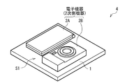
- FIG. 1 illustrates an external configuration example of the power feeding system (power feeding system 4) according to the first embodiment of the present disclosure
- FIG. 2 illustrates a block configuration example of the power feeding system 4. is there.
- the power feeding system 4 is a system (non-contact type power feeding system) that performs non-contact power transmission (power supply, power feeding) using a magnetic field (using magnetic resonance or the like; the same applies hereinafter).
- the power supply system 4 includes a power supply device 1 (primary device) and one or a plurality of electronic devices (here, two electronic devices 2A and 2B; secondary devices).
- the electronic devices 2A and 2B are placed (or close to) on the power supply surface (power transmission surface) S1 of the power supply device 1, so that the electronic device is changed from the power supply device 1 to the electronic device.
- Power transmission is performed for 2A and 2B.
- the power supply device 1 has an area of the power supply surface S1 that is the power supply target electronic device 2A,
- the mat shape (tray shape) is larger than 2B.
- the power feeding device 1 is a device (charge tray) that transmits electric power to the electronic devices 2A and 2B using a magnetic field.
- the power supply device 1 includes a power transmission device 11 including a power transmission unit 110, a high frequency power generation circuit 111, an impedance matching circuit 112, and a resonance capacitor C ⁇ b> 1 (capacitance element).
- the power transmission unit 110 includes a power transmission coil (primary coil) L1 and the like which will be described later.
- the power transmission unit 110 uses the power transmission coil L1 and the resonance capacitor C1 to perform power transmission using a magnetic field to the electronic devices 2A and 2B (specifically, the power reception unit 210 described later).
- the power transmission unit 110 has a function of radiating a magnetic field (magnetic flux) from the power feeding surface S1 toward the electronic devices 2A and 2B.
- the detailed configuration of the power transmission unit 110 will be described later (FIGS. 3 to 6).
- the high-frequency power generation circuit 111 is a circuit that generates predetermined high-frequency power (AC signal) for power transmission using, for example, power supplied from the power supply source 9 outside the power supply apparatus 1.
- the impedance matching circuit 112 is a circuit that performs impedance matching when performing power transmission. Thereby, the efficiency (transmission efficiency) in power transmission is improved.
- the impedance matching circuit 112 may not be provided depending on the configuration of the power transmission coil L1, the power receiving coil L2, which will be described later, the resonance capacitors C1 and C2, and the like.
- the resonance capacitor C1 is a capacitive element for configuring an LC resonator (main resonator, main resonance circuit) together with the power transmission coil L1, and is electrically directly or in parallel with the power transmission coil L1 or in parallel with the series. Are arranged so as to be a combination of the two.
- the resonance operation (main resonance frequency) f1 having a resonance frequency (main resonance frequency) f1 that is substantially the same as or close to the high-frequency power generated in the high-frequency power generation circuit 111. Resonance operation).
- the capacitance value of the resonance capacitor C1 is set so that the resonance frequency f1 is obtained.
- the above resonance is caused by a main resonance operation using a parasitic capacitance component (floating capacitance component) composed of a line capacitance in the power transmission coil L1 and a capacitance between the power transmission coil L1 and a power receiving coil L2 described later. If the frequency f1 is realized, the resonance capacitor C1 may not be provided.
- a parasitic capacitance component floating capacitance component
- the electronic devices 2A and 2B are, for example, a stationary electronic device represented by a television receiver, a portable electronic device including a rechargeable battery (battery) represented by a mobile phone or a digital camera, and the like.
- the electronic device includes a power receiving device 21, and a load 22 that performs a predetermined operation (an operation that exhibits a function as an electronic device) based on the power supplied from the power receiving device 21. It has.
- the power receiving device 21 includes a power receiving unit 210, an impedance matching circuit 212, a rectifying circuit 213, a voltage stabilizing circuit 214, a battery 215, and a resonance capacitor (capacitance element) C2.
- the power receiving unit 210 includes a power receiving coil (secondary coil) L2 described later.
- the power reception unit 210 has a function of receiving power transmitted from the power transmission unit 110 in the power feeding apparatus 1 using the power reception coil L2 and the resonance capacitor C2.
- the detailed configuration of the power receiving unit 210 will be described later (FIG. 3).
- the impedance matching circuit 212 is a circuit that performs impedance matching when performing power transmission.
- the impedance matching circuit 212 may not be provided depending on the configuration of the power transmission coil L1, the power receiving coil L2, which will be described later, the resonance capacitors C1 and C2, and the like.
- the rectifier circuit 213 is a circuit that rectifies the power (AC power) supplied from the power receiving unit 210 and generates DC power.
- the voltage stabilization circuit 214 performs a predetermined voltage stabilization operation based on the DC power supplied from the rectifier circuit 213 and charges the battery 215 and a battery (not shown) in the load 22. It is.
- the battery 215 stores electric power according to charging by the voltage stabilization circuit 214, and is configured using a rechargeable battery (secondary battery) such as a lithium ion battery, for example. Note that the battery 215 is not necessarily provided when only the battery in the load 22 is used.
- the resonance capacitor C2 is a capacitive element for forming an LC resonator (main resonator, main resonance circuit) together with the power receiving coil L2, and is electrically directly or in parallel with the power receiving coil L2 or in parallel in series. Are arranged so as to be a combination of the two.
- the LC resonator including the power receiving coil L2 and the resonance capacitor C2 performs a resonance operation at a resonance frequency f2 having a frequency that is substantially the same as or close to the high frequency power generated in the high frequency power generation circuit 111. Yes.
- the LC resonator in the power transmission device 11 including the power transmission coil L1 and the resonance capacitor C1 and the LC resonator in the power reception device 21 including the power reception coil L2 and the resonance capacitor C2 have substantially the same resonance.
- the main resonance operation is performed at a frequency (f1 ⁇ f2).
- the capacitance value of the resonance capacitor C2 is set so as to have such a resonance frequency f2.
- the resonance frequency f2 is realized by the main resonance operation using the parasitic capacitance component composed of the line capacitance in the power receiving coil L2, the capacity between the power transmitting coil L1 and the power receiving coil L2, and the like. If present, this resonance capacitor C2 may also be omitted.
- FIG. 3 schematically shows a schematic configuration of the power transmission unit 110 and the power reception unit 210.
- the power transmission unit 110 includes a power transmission coil L1 and the auxiliary resonance unit 3, and the power reception unit 210 includes a power reception coil L2.
- the power transmission coil L1 is a coil for performing power transmission (generating magnetic flux) using a magnetic field.
- the power receiving coil L2 is a coil for receiving power (from magnetic flux) transmitted from the power transmission unit 110.
- the auxiliary resonance unit 3 performs a predetermined resonance operation (auxiliary resonance operation).
- auxiliary resonance operation a predetermined resonance operation
- one LC resonator (auxiliary element) composed of one auxiliary coil L3 and one resonance capacitor C3 (capacitance element).
- Resonator, auxiliary resonance circuit the resonance frequency (auxiliary resonance frequency) at the time of the auxiliary resonance operation in the LC resonator in the auxiliary resonance unit 3 is assumed to be f3.
- the resonance capacitor C3 in the auxiliary resonance unit 3 may not be provided when a predetermined parasitic capacitance component is used instead.
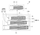
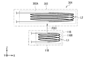
- FIG. 4 illustrates a detailed configuration example of the power transmission unit 110.
- FIG. 4A illustrates a perspective configuration example
- FIG. 4B illustrates a planar configuration example (XY planar configuration example).
- the power transmission coil L1 and the auxiliary coil L3 described above are disposed on the flat shield plate 110S so as to be insulated (physically and electrically insulated) from each other.
- the shield plate 110S is for preventing unnecessary magnetic flux leakage to a region (here, the lower side) where the power receiving coil L2 is not coupled (magnetically coupled), and is made of a magnetic material or a conductive material. However, in some cases, such a shield plate 110S may not be provided.
- the power transmission coil L1 and the auxiliary coil L3 are disposed in substantially the same plane (here, the surface (the same plane) of the shield plate 110S).
- the arrangement is not limited to this, and for example, the auxiliary coil L3 may be arranged on a plane shifted from the coil surface of the power transmission coil L1 along the vertical direction (Z-axis direction). That is, the power transmission coil L1 and the auxiliary coil L3 may be arranged in different planes.
- the degree of freedom in design (arrangement) of the auxiliary resonance unit 3 is improved.
- FIG. 4 when the power transmission coil L1 and the auxiliary coil L3 are arranged in substantially the same plane, the power transmission unit 110 can be thinned. Below, it demonstrates using the example by which these coils are arrange
- the center point CP1 of the power transmission coil L1 and the center point CP3 of the auxiliary coil L3 are located substantially on the same axis (Z axis) (here, substantially the same point).
- the structure of the power transmission unit 110 including the power transmission coil L1 and the auxiliary coil L3 is substantially symmetric in the X-axis direction and the Y-axis direction. It is possible to facilitate the flattening (uniformization) of the transmission efficiency distribution according to the electronic devices 2A and 2B).
- the inner diameter ⁇ 3 of the auxiliary coil L3 is smaller than the inner diameter ⁇ 1 of the power transmission coil L1 ( ⁇ 3 ⁇ 1).
- the power transmission coil L1 and the auxiliary coil L3 are formed to be concentric with different inner diameters.
- the structure of the power transmission coil L1 and the auxiliary coil L3 in the power transmission part 110 is not restricted to what was shown to FIG. 4 (A) and (B).
- the windings in the power transmission coil L1 and the auxiliary coil L3 are not tightly wound, but as shown in FIG. 5, for example, These windings may be sparsely wound (a predetermined gap is provided between the wires).
- each of the power transmission coil L1 and the auxiliary coil L3 may be, for example, a coil wound clockwise or a coil wound counterclockwise, and it is necessary to unify the winding direction. Absent.
- the center point CP1 of the power transmission coil L1 and the center point CP3 of the auxiliary coil L3 may be arranged so as not to be positioned on the same axis. In that case, it is possible to intentionally increase and decrease the transmission efficiency distribution according to the relative position described later (here, the arrangement positions of the electronic devices 2A and 2B with respect to the power supply device 1).
- the inner diameter ⁇ 3 of the auxiliary coil L3 may be equal to or greater than the inner diameter ⁇ 1 of the power transmission coil L1 ( ⁇ 3 ⁇ ⁇ 1). In this case, although the maximum value of the transmission efficiency itself is lowered, it is possible to expand the area where contactless power feeding is possible with a relatively high transmission efficiency.
- the resonance frequency f3 is higher than the resonance frequency f1 ( ⁇ f2) (f3> f1).
- the resonance frequency f3 is lower than the resonance frequency f1 ( ⁇ f2) (f3 ⁇ f1).
- the resonance frequency f3 is, for example, 1.1 times or more and 5.0 times or less (1.1 ⁇ (f3 / f1) ⁇ 5.0) of the resonance frequency f1 ( ⁇ f2). It is desirable that the ratio is 1.25 times or more and 3.00 times or less (1.25 ⁇ (f3 / f1) ⁇ 3.00). This is because it is easy to flatten (uniformize) the transmission efficiency distribution according to the relative position described later (here, the arrangement positions of the electronic devices 2A and 2B with respect to the power supply device 1).
- the high frequency power generation circuit 111 performs predetermined high frequency power (for transmitting power to the power transmission coil L ⁇ b> 1 and the resonance capacitor C ⁇ b> 1 (LC resonator)) in the power transmission unit 110. AC signal). Thereby, a magnetic field (magnetic flux) is generated in the power transmission coil L ⁇ b> 1 in the power transmission unit 110.
- the electronic devices 2A and 2B as power supply targets (charge targets) are placed (or close to) on the upper surface (power supply surface S1) of the power supply device 1, the power transmission coil L1 and the electronic device 2A in the power supply device 1 are placed. , 2B are close to each other in the vicinity of the power feeding surface S1.
- the electromotive force is induced in the power receiving coil L2 by being induced by the magnetic flux generated from the power transmission coil L1.
- a magnetic field is generated by interlinking with each of the power transmission coil L1 and the power reception coil L2 by electromagnetic induction or magnetic resonance.
- power is transmitted from the power transmission coil L1 side (primary side, power feeding device 1 side, power transmission unit 110 side) to the power reception coil L2 side (secondary side, electronic equipment 2A, 2B side, power reception unit 210 side). (See the power P1 shown in FIG. 2).
- the main resonance operation (resonance frequency f1) using the power transmission coil L1 and the resonance capacitor C1 is performed on the power supply device 1 side, and the power reception coil L2 and the resonance capacitor C2 are on the electronic devices 2A and 2B side. Is performed (resonance frequency f2 ⁇ f1).
- the AC power received by the power receiving coil L2 is supplied to the rectifying circuit 213 and the voltage stabilizing circuit 214, and the following charging operation is performed. That is, after this AC power is converted into predetermined DC power by the rectifier circuit 213, a voltage stabilization operation based on this DC power is performed by the voltage stabilization circuit 214, and the battery 215 or a battery in the load 22 (not shown). ) Is charged. In this way, in the electronic devices 2A and 2B, the charging operation based on the power received by the power receiving unit 210 is performed.
- FIG. 7 illustrates a schematic configuration (FIG. 7A) and power transmission characteristics (FIG. 7B) of the power supply system (power supply system 104) according to Comparative Example 1.
- the power supply system 104 of the comparative example 1 is a system that performs power transmission in a non-contact manner using a magnetic field in the same manner as the power supply system 4 (see power P101 in FIG. 7A).
- the power feeding system 104 includes a power feeding device (not shown) having the power transmission device 101 and an electronic device (not shown) having the power receiving device 21.
- the power transmission apparatus 101 has the power transmission coil L1 as shown in FIG. 7A, unlike the power transmission apparatus 11, the power transmission apparatus 101 does not have the auxiliary resonance unit 3. For this reason, the following problem occurs in Comparative Example 1. That is, for example, as shown in FIG. 7B, the magnetic field line distribution (magnetic flux density distribution) in the inner region of the power transmission coil L1 becomes non-uniform, and the power supply efficiency (transmission efficiency) at the time of power transmission (non-contact power supply) is increased. It becomes non-uniform depending on the relative position between the primary device and the secondary device (here, the position of the secondary device). This is due to the following reason.
- the power transmission unit 201A includes a power transmission coil L201 including two coils (divided coils), that is, an outer peripheral coil L201A and an inner peripheral coil L201B. That is, in the power transmission coil L201, the outer peripheral coil L201A and the inner peripheral coil L201B are arranged with a predetermined distance (inner diameter difference) therebetween.
- the outer coil L201A and the inner coil L201B are physically different from the power transmission coil L1 and the auxiliary coil L3 (physically and electrically insulated) of the present embodiment described above. Connected electrically and electrically (not insulated).
- the power transmission unit 201A does not use a split coil (for example, the inner peripheral coil L201B has an inner coil L201B, for example, as shown in the magnetic flux density distribution in FIG. 8B).
- the magnetic flux density distribution is made uniform to some extent as compared to the case where there is no (see the double line arrows in the figure). This is generated by the direction of the magnetic flux generated by the outer peripheral coil L201A and the inner peripheral coil L201B in the inner region of the inner peripheral coil L201B, as indicated by the solid and broken arrows in FIG. 8B. This is because the direction of the magnetic flux is set to be the same (here, the positive direction on the Z axis).
- the transmission efficiency depends on the relative position (here, the position of the secondary device (power receiving coil)) during power transmission.
- the relative position here, the position of the secondary device (power receiving coil)
- the direction of the magnetic flux by the outer peripheral coil L201A is not the same as the direction of the magnetic flux by the inner peripheral coil L201B.
- the part is reversed.
- the direction of the magnetic flux by the outer peripheral coil L201A and the direction of the magnetic flux by the inner peripheral coil L201B are all reversed. End up.
- part of the magnetic flux lines of magnetic force
- an increase in the magnetic flux density is suppressed to some extent near the inner end of the outer peripheral coil L201A.
- the direction of the magnetic flux equivalently passing through the power receiving coil is determined by the balance between the magnetic flux density of the magnetic field lines generated from the outer coil L201A and the magnetic flux density of the magnetic field lines generated from the inner coil L201B in the vicinity of the power receiving coil.
- the power receiving coil is arranged at a position where the directions (magnetic flux densities) of these magnetic fluxes are completely equal, the magnetic flux is equivalently canceled and does not pass through the power receiving coil. It will be extremely low and non-contact power supply will be almost impossible.
- auxiliary resonance unit 3 including the auxiliary coil L3 (physically and electrically insulated from the power transmission coil L1) configured as shown in FIGS. 3 to 5, for example.
- the resonance frequency f1 ( ⁇ f2) in the main resonance operation during power transmission using a magnetic field, and the auxiliary resonance unit 3 are different from each other (f1 ⁇ f3). Therefore, by adjusting the difference between the resonance frequencies f1 and f3, the relative position between the power supply device 1 and the electronic devices 2A and 2B (here, the positions of the electronic devices 2A and 2B) and the transmission efficiency during power transmission (Positional characteristics) change. That is, the main resonance operation (position distribution of transmission efficiency) during power transmission is controlled using the auxiliary resonance operation in the auxiliary resonance unit 3.
- the transmission efficiency with respect to the change in the relative position when the resonance frequency f3 is set to be higher than the resonance frequency f1 (f3> f1), the transmission efficiency with respect to the change in the relative position. Fluctuations (transmission efficiency non-uniformity depending on the relative position) are reduced. That is, compared with the case where the resonance frequencies f1 and f3 are equal to each other (corresponding to the case of the comparative example 2), the transmission efficiency distribution is flattened (uniformized) according to the relative position. Specifically, the coupling coefficient (magnetic coupling coefficient), which is one of the main parameters that determine transmission efficiency, is less likely to fluctuate even if the relative position changes (the coupling coefficient is almost dependent on the relative position).
- the resonance frequency f3 when the resonance frequency f3 is set to be lower than the resonance frequency f1 (f3 ⁇ f1), the transmission efficiency with respect to the change in the relative position. Can be arbitrarily controlled. Specifically, for example, it is possible to selectively provide a region having a relatively high transmission efficiency and a region having a relatively low transmission efficiency (power transmission is performed in a selective region on the power feeding surface S1).
- FIG. 9 to FIG. 11 show various data according to examples of the present embodiment.
- the power transmission unit 110 having the configuration shown in FIGS. 4A and 4B is used.
- the inner diameter ⁇ 1 120 mm of the power transmission coil L1
- the power receiving coil L2 having an outer diameter ⁇ 10 mm was disposed about 6 mm away from the upper surface of the power transmitting coil L1 in the vertical direction (Z-axis direction).
- the resonance frequency f2 ⁇ f1 was set on the electronic devices 2A and 2B side.
- FIG. 9A shows an example of a change in transmission characteristics due to the arrangement of the power receiving coil L2.
- the transmission characteristics when the power receiving coil L2 is moved in the horizontal direction (in the XY plane) with reference to the position described above (movement length d) are measured.
- S 21 (S parameter) on the vertical axis is a parameter related to power supply efficiency (transmission efficiency).
- FIG. 9B shows an example of a phase characteristic change due to the arrangement of the power receiving coil L2.
- FIG. 9B there is almost no phase change at the frequency (1 ⁇ f1) in the vicinity of the resonance frequency f1 at the time of power transmission (see reference numeral G21 in the figure), whereas the resonance frequency in the auxiliary resonance unit 3 It can be seen that at the frequency near f2 (2 ⁇ f1), the phase is greatly changed (the phase is reversed) (see symbol G22 in the figure).
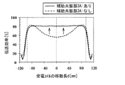
- FIG. 10A shows an example of a change in the position characteristic (here, the characteristic indicating the relationship between the movement length d of the power receiving coil L2 and the transmission efficiency) depending on the presence or absence of the auxiliary resonance unit 3.
- the auxiliary resonance unit 3 by providing the auxiliary resonance unit 3, the transmission efficiency in the gap region between the power transmission coil L1 and the auxiliary coil L3 is improved (see the arrow in the figure), and the transmission efficiency distribution is almost uniform. It can be seen that
- the vibration frequency f3 is conversely lower than the resonance frequency f1 (f3 ⁇ f1), for example, as shown by the dashed arrow in FIG.
- the degree of change in the position characteristics when the resonance frequency f3 is changed depends on the configuration and arrangement of the power transmission coil L1 and the auxiliary coil L3, the influence of the surrounding metal and the surrounding magnetic material inside the housing of the power feeding device 1, It depends on the influence received from the metal or magnetic material used in the housing of the electronic devices 2A and 2B. Therefore, the optimum value of the resonance frequency f3 may be set in consideration of these effects. That is, the resonance frequency f3 is set to such a frequency that the phase inversion and the extreme decrease in transmission efficiency as described in FIGS. 9A and 9B do not occur near the resonance frequency f1 during power transmission. You can say that.
- FIG. 11A shows an example of a change in position characteristics when the inner diameter ⁇ 3 of the auxiliary coil L3 is changed
- FIG. 11B shows a position when the number of turns n3 in the auxiliary coil L3 is changed.
- Each example represents a characteristic change.
- 11A and 11B it can be seen that the position characteristics can be slightly changed by changing the inner diameter ⁇ 3, the number of turns n3, etc. of the auxiliary coil L3.
- FIG. 11A shows that the transmission efficiency is slightly improved as the inner diameter ⁇ 3 of the auxiliary coil L3 increases.
- FIG. 11B shows that the transmission efficiency is slightly improved as the number of turns n3 in the auxiliary coil L3 increases.
- the shape and arrangement of the auxiliary coil L3, the resonance frequency f3, and the like are parameters when changing the position characteristics (uniformizing the transmission efficiency distribution), and the resonance frequency f3 is particularly important. You know that is a parameter.
- the resonance frequency f1 in the main resonance operation during power transmission using a magnetic field and the resonance frequency f3 in the LC resonator in the auxiliary resonance unit 3 are different from each other. Therefore, by adjusting the difference between the resonance frequencies f1 and f3, the relationship between the relative position of the power transmission side (power feeding device 1) and the power receiving side (electronic devices 2A and 2B) and the transmission efficiency during power transmission ( Position characteristics) can be changed. Therefore, when power transmission (non-contact power feeding) is performed between devices using a magnetic field, transmission efficiency control corresponding to the position of the device can be performed.
- the transmission efficiency fluctuates with respect to the change in the relative position (the transmission efficiency depends on the relative position). (Uniformity) can be reduced. That is, compared with the case where the resonance frequencies f1 and f3 are equal to each other (corresponding to the case of the comparative example 2), the transmission efficiency distribution according to the relative position can be flattened (uniformized). Therefore, it is possible to construct a non-contact power feeding system that has no dead zone in a wide area on the power feeding surface S1 and that can obtain substantially uniform transmission efficiency. In addition, it is also possible to obtain effects such as improvement in power supply stability during non-contact power supply, improvement in the degree of freedom in arrangement of secondary side devices (electronic devices 2A and 2B), and improvement in detection capability of dissimilar metals. It becomes.
- the inner diameter ⁇ 3 of the auxiliary coil L3 is made smaller than the inner diameter ⁇ 1 of the power transmission coil L1 ( ⁇ 3 ⁇ 1), the following effects are obtained. That is, in the absence of the auxiliary coil L3, the magnetic field near the center of the power transmission coil L1 that was relatively weak can be reinforced, and the transmission efficiency distribution according to the relative position can be further uniformized. .
- FIG. 12 illustrates a schematic configuration example of a power supply system (power supply system 4A) according to the second embodiment.
- the power feeding system 4A of the present embodiment is a system that performs power transmission in a non-contact manner using a magnetic field, similarly to the power feeding system 4, and includes a power feeding device (not shown) having a power transmission device 11A and a power receiving device 21. 1 or a plurality of electronic devices (not shown). That is, the power supply system 4A includes a power transmission device 11A instead of the power transmission device 11 in the power supply system 4, and the other configurations are the same.
- the power transmission device 11A includes a power transmission unit 110A having a power transmission coil L1 and an auxiliary resonance unit 3A.
- the auxiliary resonance unit 3A includes a plurality (here, two) of auxiliary coils L31 and L32 and a plurality (here, two) of resonance capacitors C31 and C32 (capacitance elements).
- a plurality (two in this case) of LC resonators are provided.
- the auxiliary coil L31 and the resonance capacitor C31 constitute one LC resonator
- the auxiliary coil L32 and the resonance capacitor C32 constitute one LC resonator.
- the resonance frequency (auxiliary resonance frequency) at the time of the auxiliary resonance operation in the LC resonator including the auxiliary coil L31 and the resonance capacitor C31 is assumed to be f31.
- a resonance frequency (auxiliary resonance frequency) at the time of an auxiliary resonance operation in the LC resonator including the auxiliary coil L32 and the resonance capacitor C32 is defined as f32.
- the resonance capacitors C31 and C32 in the auxiliary resonance unit 3A may not be provided when a predetermined parasitic capacitance component is used instead.
- FIG. 13 illustrates a detailed configuration example (XY plane configuration example) of the power transmission unit 110A.
- the power transmission coil L1 and the two auxiliary coils L31 and L32 are arranged on the shield plate 110S so as to be insulated (physically and electrically insulated) from each other.
- the two auxiliary coils L31 and L32 may not be insulated in some cases (may be physically and electrically connected).
- the power transmission coil L1 and the auxiliary coils L31 and L32 are disposed in substantially the same plane (here, the surface (the same plane) of the shield plate 110S).
- the arrangement is not limited to such an arrangement.
- the auxiliary coils L31 and L32 may be arranged on a plane shifted from the coil surface of the power transmission coil L1 along the vertical direction (Z-axis direction). Good. That is, the power transmission coil L1 and the auxiliary coils L31 and L32 may be arranged in different planes. When arranged in this way, the degree of freedom in design (arrangement) of the auxiliary resonance unit 3A is improved.
- the power transmission unit 110A when the power transmission coil L1 and the auxiliary coils L31 and L32 are arranged in substantially the same plane, the power transmission unit 110A can be thinned. Below, it demonstrates using the example by which these coils are arrange
- the center point CP1 of the power transmission coil L1, the center point CP31 of the auxiliary coil L31, and the center point CP32 of the auxiliary coil L32 are substantially coaxial (Z-axis) (here, (Same point). Accordingly, the structure of the power transmission unit 110A configured to include the power transmission coil L1 and the auxiliary coils L31 and L32 is substantially symmetric in the X-axis direction and the Y-axis direction. It is possible to facilitate the uniformization of the efficiency distribution.
- the inner diameters ⁇ 31 ( ⁇ 31x, ⁇ 31y) and ⁇ 32 ( ⁇ 32x, ⁇ 32y) of the auxiliary coils L31, L32 are smaller than the inner diameter ⁇ 1 ( ⁇ 1x, ⁇ 1y) of the power transmission coil L1, respectively (( ⁇ 31x, ⁇ 32x) ⁇ 1x , ( ⁇ 31y, ⁇ 32y) ⁇ 1y).
- the inner diameters ⁇ 31 ( ⁇ 31x, ⁇ 31y) and ⁇ 32 ( ⁇ 32x, ⁇ 32y) of the auxiliary coils L31, L32 are different from each other ( ⁇ 31x ⁇ ⁇ 32x, ⁇ 31y ⁇ ⁇ 32y).
- the power transmission coil L1, the auxiliary coil L31, and the auxiliary coil L32 are formed to be concentric circles having different inner diameters.
- the power transmission coil L1 and the auxiliary coils L31 and L32 each have an inner surface shape that exhibits anisotropy (for example, an ellipse shape, a rectangular shape, an oval shape, or the like). Therefore, it is desirable to satisfy the following conditions for each inner diameter difference. Specifically, the difference between the inner diameters of the power transmission coil L1 and the outermost auxiliary coil L31 and the difference between the inner diameters of the adjacent auxiliary coils L31 and L32 are short in the inner shape showing the anisotropy. It is desirable that it is larger in the longitudinal direction (here, the Y-axis direction) than in the hand direction (here, the X-axis direction). That is, it is desirable that g1y> g1x and g2y> g2x are satisfied. This is because the transmission efficiency distribution according to the relative position described above can be made even more effective.
- anisotropy for example, an ellipse shape, a rectangular shape, an oval shape, or the like. Therefore
- the configurations of the power transmission coil L1 and the auxiliary coils L31 and L32 in the power transmission unit 110A are not limited to those illustrated in FIG. 13 as in the case of the power transmission unit 110 described in the first embodiment. It is good also as a structure of. That is, for example, the power transmission coil L1 and the auxiliary coils L31 and L32 may each have an inner surface shape (circular shape or the like) showing isotropic properties. Further, for each inner diameter difference, at least a part of the above relationship may not be established.
- the resonance frequency f1 ( ⁇ f2) in the main resonance operation during power transmission using a magnetic field and the LC resonator in the auxiliary resonance unit 3A. Is different from each other (f1 ⁇ (f31, f32)).
- the resonance frequencies f31 and f32 are higher than the resonance frequency f1 ( ⁇ f2) ((f31, f32)> f1).
- the resonance frequencies f31 and f32 are lower than the resonance frequency f1 ( ⁇ f2) ((f31, f32) ⁇ f1).
- the resonance frequency f1 in the main resonance operation during power transmission using a magnetic field is different from the resonance frequencies f31 and f32 in the LC resonator in the auxiliary resonance unit 3A. Therefore, the same effect can be obtained by the same operation as that of the first embodiment. That is, when power transmission (non-contact power feeding) is performed between devices using a magnetic field, transmission efficiency control corresponding to the position of the device can be performed. Further, when the resonance frequencies f31 and f32 are set to be higher than the resonance frequency f1 ((f31, f32)> f1), the transmission efficiency fluctuates with respect to the relative position change (depending on the relative position). Non-uniformity in transmission efficiency) can be reduced.
- the auxiliary resonance unit 3A includes a plurality of LC resonators including a plurality of auxiliary coils L31 and L32 and a plurality of resonance capacitors C31 and C32. It can be said that the advantage of the above effect is great when the region is particularly wide.
- FIG. 15 shows data according to an example of the present embodiment (an example of a change in position characteristics depending on the presence / absence of the auxiliary resonance unit 3A).
- the transmission efficiency in the gap region between the power transmission coil L1 and the auxiliary coils L31 and L32 is improved (see the arrow in the figure), and a substantially uniform transmission efficiency distribution is obtained.
- the inner region of the power transmission coil L1 is wider (inner diameter is larger) than the example of the first embodiment, compared with the result shown in FIG. It can be seen that the improvement effect is great.
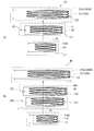
- FIGS. 16A and 16B show a schematic configuration example of a power supply system (power supply systems 4B and 4C) according to the third embodiment.
- Each of the power feeding systems 4B and 4C according to the present embodiment is a system that performs power transmission in a non-contact manner using a magnetic field in the same manner as the power feeding system 4.
- the electronic device (secondary device) that is the power supply target is larger than the power supply device (primary device). .
- this corresponds to a case where the power receiving surface in the electronic device is larger than the power transmitting surface (power feeding surface) in the power supply apparatus.
- a power feeding system 4B shown in FIG. 16A includes a power feeding device (not shown) having a power transmission device 11B and one or a plurality of electronic devices (not shown) having a power receiving device 21B.
- the power transmission device 11B includes a power transmission unit 110B having a power transmission coil L1
- the power reception device 21B includes a power reception unit 210B having a power reception coil L2 and an auxiliary resonance unit 3. That is, the power receiving unit 210B has one LC resonator composed of one auxiliary coil L3 and one resonance capacitor C3.
- the power supply system 4C illustrated in FIG. 16B includes a power supply device (not shown) having the power transmission device 11B and one or more electronic devices (not shown) having the power reception device 21C.
- the power receiving device 21C includes a power receiving unit 210C having a power receiving coil L2 and an auxiliary resonance unit 3A.
- the power receiving unit 210C has two LC resonators including two auxiliary coils L31 and L32 and two resonance capacitors C31 and C32.
- the configuration of the auxiliary resonance units 3 and 3A in the present embodiment is basically the same as that described in the first and second embodiments.
- the resonance frequency f2 ( ⁇ f1) in the main resonance operation in the power receiving devices 21B and 21C and the resonance frequencies f3, f31, and f32 in the LC resonators in the auxiliary resonance units 3 and 3A are different from each other ( f2 ⁇ (ff3, f31, f32)).
- the resonance frequencies f3, f31, and f32 are higher than the resonance frequency f2 ( ⁇ f1) ((f3, f31, f32)> f2).
- the resonance frequencies f3, f31, and f32 are lower than the resonance frequency f2 ( ⁇ f1) ((f3, f31, f32) ⁇ f2).
- the auxiliary resonance portions 3 and 3A are provided on the power receiving devices 21B and 21C (electronic device side), the arrangement position (relative position) of the power feeding device in the power receiving surface of the electronic device. It becomes possible to reduce the nonuniformity of the transmission efficiency depending on the.
- the auxiliary resonance units 3 and 3A are not provided on the power reception device 302 side (electronic device side) including the power reception unit 302A. Compared to the case, it is possible to reduce non-uniformity in transmission efficiency depending on the position of the power feeding device in the power receiving surface of the electronic device.
- a relatively large power transmission surface in both the power supply apparatus (primary device) and the electronic device (secondary device). This corresponds to the case of having a power receiving surface.
- the power feeding system 4D shown in FIG. 18A includes a power feeding device (not shown) having the power transmission device 11 and one or more electronic devices (not shown) having the power receiving device 21B.
- the power transmission device 11 includes a power transmission unit 110 having a power transmission coil L1 and an auxiliary resonance unit 3
- the power reception device 21B includes a power reception unit 210B having a power reception coil L2 and the auxiliary resonance unit 3. That is, both the power transmitting device 11 and the power receiving device 21B include the auxiliary resonance unit 3 having one LC resonator including one auxiliary coil L3 and one resonance capacitor C3.
- the 18B includes a power feeding device (not shown) having a power transmission device 11A and one or a plurality of electronic devices (not shown) having a power receiving device 21C.
- the power transmission device 11A includes a power transmission unit 110A having a power transmission coil L1 and an auxiliary resonance unit 3A
- the power reception device 21C includes a power reception unit 210C having a power reception coil L2 and an auxiliary resonance unit 3A. That is, both of the power transmission device 11A and the power reception device 21C include the auxiliary resonance unit 3A having two LC resonators including two auxiliary coils L31 and L32 and two resonance capacitors C31 and C32.
- the power feeding system 4F shown in FIG. 19A includes a power feeding device (not shown) having a power transmission device 11A and one or a plurality of electronic devices (not shown) having a power receiving device 21B.
- the power transmission device 11A includes a power transmission unit 110A having a power transmission coil L1 and an auxiliary resonance unit 3A
- the power reception device 21B includes a power reception unit 210B having a power reception coil L2 and the auxiliary resonance unit 3.
- the power transmission device 11A includes an auxiliary resonance unit 3A having two LC resonators including two auxiliary coils L31 and L32 and two resonance capacitors C31 and C32, while the power reception device 21B includes one auxiliary coil.
- An auxiliary resonance unit 3 having one LC resonator composed of L3 and one resonance capacitor C3 is provided.
- the power supply system 4G shown in FIG. 19B includes a power supply device (not shown) having the power transmission device 11 and one or more electronic devices (not shown) having the power reception device 21C.
- the power transmission device 11 includes a power transmission unit 110 having a power transmission coil L1 and an auxiliary resonance unit 3
- the power reception device 21C includes a power reception unit 210C having a power reception coil L2 and an auxiliary resonance unit 3A. That is, the power transmission device 11 includes the auxiliary resonance unit 3 having one LC resonator including one auxiliary coil L3 and one resonance capacitor C3, while the power reception device 21C includes two auxiliary coils L31 and L32.
- An auxiliary resonance unit 3A having two LC resonators composed of two resonance capacitors C31 and C32 is provided.
- auxiliary resonance units 3 and 3A in the present embodiment is basically the same as that described in the first to third embodiments.
- the auxiliary resonance units 3 and 3A are provided on both the power transmission device (power supply device) side and the power reception device (electronic device) side, the electrons on the power transmission surface (power supply surface) of the power supply device are provided. It is possible to reduce non-uniformity in transmission efficiency depending on the arrangement position of the device and the arrangement position (relative position) of the power feeding device in the power receiving surface of the electronic device.
- ⁇ Fifth embodiment> [Configuration of Power Supply System 4H, 4I, 4J, 4K] 20A, 20B, 21A, and 21B show schematic configuration examples of the power supply system (power supply systems 4H, 4I, 4J, and 4K) according to the fifth embodiment. It is.
- Each of the power feeding systems 4H, 4I, 4J, and 4K according to the present embodiment is a system that performs non-contact power transmission using a magnetic field in the same manner as the power feeding system 4.
- the power feeding system of the present embodiment includes a power feeding device, one or a plurality of electronic devices, and an auxiliary device having an auxiliary resonance unit.
- a power feeding system 4H illustrated in FIG. 20A includes a power feeding device (not shown) having a power transmission device 11H, one or a plurality of electronic devices (not shown) having a power receiving device 21, and an auxiliary resonance unit 3. And an auxiliary device 41 having the same.
- the power transmission device 11H includes a power transmission unit 110H having a power transmission coil L1
- the power reception device 21 includes a power reception unit 210 having a power reception coil L2. That is, the auxiliary device 41 that is separate from the power supply device (power transmission device 11H) and the electronic device (power reception device 21) has one LC resonator including one auxiliary coil L3 and one resonance capacitor C3.
- An auxiliary resonance unit 3 is provided.
- the power transmission device 11H and the power transmission unit 110H have the same configuration as the power transmission device 101 and the power transmission unit 101A described above, respectively.
- a power feeding system 4I shown in FIG. 20B includes a power feeding device (not shown) having a power transmission device 11H, one or a plurality of electronic devices (not shown) having a power receiving device 21, and an auxiliary resonance unit 3A. And an auxiliary device 41A. That is, the auxiliary device 41A, which is separate from the power feeding device (power transmission device 11H) and the electronic device (power reception device 21), includes two LCs including two auxiliary coils L31 and L32 and two resonance capacitors C31 and C32. An auxiliary resonance unit 3A having a resonator is provided.
- a power feeding system 4J shown in FIG. 21A includes a power feeding device (not shown) having a power transmission device 11B, one or a plurality of electronic devices (not shown) having a power receiving device 21J, and an auxiliary resonance unit 3. And an auxiliary device 41 having the same.
- the power transmission device 11B includes a power transmission unit 110B having a power transmission coil L1
- the power reception device 21J includes a power reception unit 210J having a power reception coil L2. That is, the auxiliary device 41 that is separate from the power supply device (power transmission device 11B) and the electronic device (power reception device 21J) has one LC resonator composed of one auxiliary coil L3 and one resonance capacitor C3.
- An auxiliary resonance unit 3 is provided. Note that the power receiving device 21J and the power receiving unit 210J have the same configuration as the power receiving device 302 and the power receiving unit 302A described above, respectively.
- a power feeding system 4K shown in FIG. 21B includes a power feeding device (not shown) having a power transmission device 11B, one or more electronic devices (not shown) having a power receiving device 21J, and an auxiliary resonance unit 3A. And an auxiliary device 41A. That is, the auxiliary device 41A, which is separate from the power supply device (power transmission device 11B) and the electronic device (power reception device 21J), includes two LCs including two auxiliary coils L31 and L32 and two resonance capacitors C31 and C32. An auxiliary resonance unit 3A having a resonator is provided.
- the auxiliary resonance unit 3 or the auxiliary resonance unit 3A is provided in another device (auxiliary devices 41 and 41A) that is separate from the power feeding device and the electronic device.
- auxiliary devices 41 and 41A In the existing non-contact power feeding system, it is possible to obtain the above-described effects only by adding the auxiliary devices 41 and 41A.
- each coil (power transmission coil, power reception coil, auxiliary coil) has a spiral shape (planar shape).
- a spiral shape plane shape
- Each coil may be formed by a multilayer spiral shape or a helical shape in which a winding is wound in the thickness direction.
- each coil is not only a wound coil composed of a conductive wire, but also a conductive pattern coil composed of a printed circuit board, a flexible printed circuit board, or the like. It may be.
- the LC resonator may be configured using a loop-shaped conductive loop instead of the coil-shaped auxiliary coil.
- each resonance capacitor (particularly, the resonance capacitor in the auxiliary resonance unit) is not limited to the case where a fixed capacitance value is used, and a configuration in which the capacitance value can be made variable (for example, a switch or the like). For example, a configuration in which connection paths of a plurality of capacitor elements are switched). In such a configuration, the resonance frequency can be controlled (optimized) by adjusting the capacitance value.
- auxiliary resonance unit described in the above embodiments and the like is provided in at least one of the power feeding device, the electronic device, and another device that is separate from the power feeding device and the electronic device. Just do it.
- the respective components such as the power feeding device and the electronic device have been specifically described. However, it is not necessary to include all the components, and further include other components. Also good.
- a communication function for example, in a power feeding device (power transmission device) or an electronic device (power receiving device), a communication function, some control function, a display function, a function for authenticating a secondary device, and a secondary device are on the primary device. A function for discriminating this, a function for detecting mixing of different metals, and the like may be installed.
- the present invention is not limited to this case, and one electronic device is provided in the power feeding system. May be provided.
- a charging tray for a small electronic device such as a mobile phone
- CE device small electronic device
- a power feeding device such as a household charging tray is used. Is not limited, and can be applied as a charger for various electronic devices. Further, it is not necessarily a tray, and may be a stand for an electronic device such as a so-called cradle.
- this technique can also take the following structures.
- the power feeding device according to (1), wherein the auxiliary resonance frequency is lower than the main resonance frequency.
- Each of the power transmission coil and each auxiliary coil has an inner shape showing anisotropy, The difference value between the inner diameters of the power transmission coil and the outermost auxiliary coil and the difference value between the inner diameters of adjacent auxiliary coils are larger in the longitudinal direction than in the short direction in the inner surface shape. ) Or (11). (13) The power feeding device according to any one of (8) to (12), wherein the power transmission coil and each auxiliary coil in the plurality of resonators are disposed in substantially the same plane. (14) Each of the auxiliary resonance frequencies in the plurality of resonators is different from each other. The power feeding device according to any one of (8) to (13).
- the power supply apparatus includes a power transmission unit including a power transmission coil for performing the power transmission using a magnetic field,
- the electronic device has a power reception unit including a power reception coil for receiving power transmitted from the power transmission unit,
- An auxiliary resonance unit including one or a plurality of resonators is provided that indicates an auxiliary resonance frequency that is different from the main resonance frequency in the main resonance operation using the power transmission coil or the power reception coil during the power transmission.
- Power supply system (18) The power feeding system according to (17), wherein the auxiliary resonance unit is provided in an auxiliary device as the other device.
- a power reception unit having a power reception coil for receiving power transmitted using a magnetic field and an auxiliary resonance unit including one or more resonators; An electronic apparatus in which a main resonance frequency in a main resonance operation using the power receiving coil during power transmission and an auxiliary resonance frequency in the resonator are different from each other. (20) The electronic apparatus according to (19), wherein the main resonance operation is performed using the power receiving coil and a predetermined capacitive element or parasitic capacitance component.
Landscapes
- Engineering & Computer Science (AREA)
- Power Engineering (AREA)
- Computer Networks & Wireless Communication (AREA)
- Physics & Mathematics (AREA)
- Electromagnetism (AREA)
- Charge And Discharge Circuits For Batteries Or The Like (AREA)
Abstract
Description
1.第1の実施の形態(1次側機器内に、1つの共振器を有する補助共振部を設けた例)
2.第2の実施の形態(1次側機器内に、複数の共振器を有する補助共振部を設けた例)
3.第3の実施の形態(2次側機器内に補助共振部を設けた例)
4.第4の実施の形態(1次側機器内および2次側機器内に補助共振部を設けた例)
5.第5の実施の形態(補助共振部を1次側機器・2次側機器とは別体として設けた例)
6.変形例
Hereinafter, embodiments of the present disclosure will be described in detail with reference to the drawings. The description will be given in the following order.
1. 1st Embodiment (example which provided the auxiliary | assistant resonance part which has one resonator in the primary side apparatus)
2. Second Embodiment (Example in which an auxiliary resonance unit having a plurality of resonators is provided in the primary device)
3. Third embodiment (example in which an auxiliary resonance unit is provided in the secondary device)
4). Fourth embodiment (example in which an auxiliary resonance unit is provided in the primary device and the secondary device)
5. Fifth embodiment (example in which the auxiliary resonance unit is provided separately from the primary side device and the secondary side device)
6). Modified example
[給電システム4の全体構成]
図1は、本開示の第1の実施の形態に係る給電システム(給電システム4)の外観構成例を表したものであり、図2は、この給電システム4のブロック構成例を表したものである。給電システム4は、磁界を用いて(磁気共鳴等を利用して;以下同様)、非接触に電力伝送(電力供給,給電)を行うシステム(非接触型の給電システム)である。この給電システム4は、給電装置1(1次側機器)と、1または複数の電子機器(ここでは2つの電子機器2A,2B;2次側機器)とを備えている。 <First Embodiment>
[Overall configuration of power supply system 4]
FIG. 1 illustrates an external configuration example of the power feeding system (power feeding system 4) according to the first embodiment of the present disclosure, and FIG. 2 illustrates a block configuration example of the
給電装置1は、上記したように、磁界を用いて電子機器2A,2Bに対して電力伝送を行うもの(充電トレー)である。この給電装置1は、例えば図2に示したように、送電部110、高周波電力発生回路111、インピーダンス整合回路112および共振用キャパシタC1(容量素子)を有する送電装置11を備えている。 (Power supply device 1)
As described above, the
電子機器2A,2Bは、例えば、テレビ受像機に代表される据え置き型電子機器や、携帯電話やデジタルカメラに代表される、充電池(バッテリー)を含む携帯型の電子機器等からなる。この電子機器は、例えば図2に示したように、受電装置21と、この受電装置21から供給される電力に基づいて所定の動作(電子機器としての機能を発揮させる動作)を行う負荷22とを備えている。また、受電装置21は、受電部210、インピーダンス整合回路212、整流回路213、電圧安定化回路214、バッテリー215および共振用キャパシタ(容量素子)C2を有している。 (
The
図3は、送電部110および受電部210の概略構成を模式的に表したものである。送電部110は、送電コイルL1および補助共振部3を有し、受電部210は、受電コイルL2を有している。 [Detailed configuration of
FIG. 3 schematically shows a schematic configuration of the
図4は、送電部110の詳細構成例を表したものであり、図4(A)は斜視構成例を、図4(B)は平面構成例(X-Y平面構成例)をそれぞれ示す。送電部110では、平板状のシールド板110S上に、上記した送電コイルL1および補助コイルL3が、互いに絶縁(物理的および電気的に絶縁)されるように配設されている。 (Detailed configuration of power transmission unit 110)
4 illustrates a detailed configuration example of the
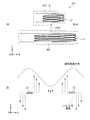
ここで本実施の形態では、図6(A),(B)に示したように、電力伝送の際の送電コイルL1を用いた主共振動作における共振周波数f1(≒f2)と、補助共振部3内のLC共振器における共振周波数f3とが、互いに異なっている(f1≠f3)。 (Relationship between resonance frequencies f1 and f3)
Here, in the present embodiment, as shown in FIGS. 6A and 6B, the resonance frequency f1 (≈f2) in the main resonance operation using the power transmission coil L1 during power transmission, and the
(1.全体動作の概要)
この給電システム4では、給電装置1において、高周波電力発生回路111が送電部110内の送電コイルL1および共振用キャパシタC1(LC共振器)に対して、電力伝送を行うための所定の高周波電力(交流信号)を供給する。これにより、送電部110内の送電コイルL1において磁界(磁束)が発生する。このとき、給電装置1の上面(給電面S1)に、給電対象(充電対象)としての電子機器2A,2Bが置かれる(または近接する)と、給電装置1内の送電コイルL1と電子機器2A,2B内の受電コイルL2とが、給電面S1付近にて近接する。 [Operation and effect of power feeding system 4]
(1. Overview of overall operation)
In the
次に、本実施の形態における特徴的部分の1つである補助共振部3の作用について、比較例(比較例1,2)と比較しつつ詳細に説明する。 (2. Action of auxiliary resonance unit 3)
Next, the operation of the
図7は、比較例1に係る給電システム(給電システム104)の概略構成(図7(A))および電力伝送特性(図7(B))を表したものである。この比較例1の給電システム104は、給電システム4と同様に磁界を用いて非接触に電力伝送を行うシステムである(図7(A)中の電力P101参照)。給電システム104は、送電装置101を有する給電装置(図示せず)と、受電装置21を有する電子機器(図示せず)とを備えている。 (Comparative Example 1)
FIG. 7 illustrates a schematic configuration (FIG. 7A) and power transmission characteristics (FIG. 7B) of the power supply system (power supply system 104) according to Comparative Example 1. The
一方、比較例2に係る給電システムでは、例えば図8(A)に示した平面構成(X-Y平面構成)からなる送電部201Aを用いて、電力伝送(非接触給電)を行っている。この送電部201Aは、外周コイルL201Aおよび内周コイルL201Bの2つのコイル(分割コイル)からなる送電コイルL201を有している。すなわち、この送電コイルL201では、外周コイルL201Aおよび内周コイルL201Bが、互いに所定の距離(内径差)を隔てて配置されている。ただし、この送電コイルL201では、前述した本実施の形態の送電コイルL1および補助コイルL3(物理的および電気的に絶縁されている)とは異なり、外周コイルL201Aと内周コイルL201Bとが、物理的および電気的に接続されている(絶縁されていない)。 (Comparative Example 2)
On the other hand, in the power feeding system according to Comparative Example 2, power transmission (non-contact power feeding) is performed using the power transmission unit 201A having a planar configuration (XY planar configuration) illustrated in FIG. 8A, for example. The power transmission unit 201A includes a power transmission coil L201 including two coils (divided coils), that is, an outer peripheral coil L201A and an inner peripheral coil L201B. That is, in the power transmission coil L201, the outer peripheral coil L201A and the inner peripheral coil L201B are arranged with a predetermined distance (inner diameter difference) therebetween. However, in the power transmission coil L201, the outer coil L201A and the inner coil L201B are physically different from the power transmission coil L1 and the auxiliary coil L3 (physically and electrically insulated) of the present embodiment described above. Connected electrically and electrically (not insulated).
これに対して本実施の形態では、例えば図3~図5に示したよう構成の補助コイルL3(送電コイルL1とは物理的および電気的に絶縁されている)を含む補助共振部3を送電部110内に設けることにより、例えば上記比較例2における問題を解消している。 (This embodiment)
On the other hand, in the present embodiment, power is transmitted through the
ここで、図9~図11は、本実施の形態の実施例に係る各種データを示したものである。この実施例では、図4(A),(B)に示した構成の送電部110を用いた。具体的には、送電コイルL1の内径φ1=120mm、補助コイルL3の内径φ3=60mm、補助コイルL3における巻き数n3=5、共振周波数f3=2×f1とした。そして、外径φ=10mmの受電コイルL2を、送電コイルL1の上面から垂直方向(Z軸方向)へ6mmほど離して配置した。なお、電子機器2A,2B側では、共振周波数f2≒f1となるように設定した。 (Example of the first embodiment)
Here, FIG. 9 to FIG. 11 show various data according to examples of the present embodiment. In this embodiment, the
[給電システム4Aの構成]
図12は、第2の実施の形態に係る給電システム(給電システム4A)の概略構成例を表したものである。本実施の形態の給電システム4Aは、給電システム4と同様に磁界を用いて非接触に電力伝送を行うシステムであり、送電装置11Aを有する給電装置(図示せず)と、受電装置21を有する1または複数の電子機器(図示せず)とを備えている。すなわち、この給電システム4Aは、給電システム4において、送電装置11の代わりに送電装置11Aを備えたものであり、他の構成は同様となっている。 <Second Embodiment>
[Configuration of
FIG. 12 illustrates a schematic configuration example of a power supply system (
図13は、送電部110Aの詳細構成例(X-Y平面構成例)を表したものである。送電部110Aでは、シールド板110S上に、上記した送電コイルL1および2つの補助コイルL31,L32が、互いに絶縁(物理的および電気的に絶縁)されるように配設されている。ただし、2つの補助コイルL31,L32同士は、場合によっては絶縁されてなくてもよい(物理的および電気的に繋がっていてもよい)。 (Detailed configuration of
FIG. 13 illustrates a detailed configuration example (XY plane configuration example) of the
ここで、本実施の形態においても第1の実施の形態と同様に、磁界を用いた電力伝送の際の主共振動作における共振周波数f1(≒f2)と、補助共振部3A内のLC共振器における共振周波数f31,f32とが、互いに異なっている(f1≠(f31,f32))。具体的には、例えば図14(A)に示したように、共振周波数f31,f32がそれぞれ、共振周波数f1(≒f2)よりも高い周波数となっている((f31,f32)>f1)。あるいは、例えば図14(B)に示したように、共振周波数f31,f32がそれぞれ、共振周波数f1(≒f2)よりも低い周波数となっている((f31,f32)<f1)。 (Relationship between resonance frequencies f1, f31, and f32)
Here, also in the present embodiment, as in the first embodiment, the resonance frequency f1 (≈f2) in the main resonance operation during power transmission using a magnetic field and the LC resonator in the
本実施の形態の給電システム4Aでは、磁界を用いた電力伝送の際の主共振動作における共振周波数f1と、補助共振部3A内のLC共振器における共振周波数f31,f32とが互いに異なっているようにしたので、第1の実施の形態と同様の作用により同様の効果を得ることが可能である。すなわち、磁界を用いて機器間で電力伝送(非接触給電)を行う際に、機器の位置に対応した伝送効率制御を行うことが可能となる。また、共振周波数f31,f32が共振周波数f1よりも高い周波数となるように設定した場合((f31,f32)>f1)には、相対的位置の変化に対する伝送効率の変動(相対的位置に依存した伝送効率の不均一性)を低減することが可能となる。 [Operation / Effect of
In the
ここで、図15は、本実施の形態の実施例に係るデータを示したもの(補助共振部3Aの有無による位置特性変化の一例)である。この実施例では、図13に示した構成の送電部110Aを用い、送電コイルL1における長手方向の内径φ1y=188mm、短手方向の内径φ1x=119mmとした。また、補助コイルL31では、長手方向の内径φ31y=141mm、短手方向の内径φ31x=92mmとし、補助コイルL32では、長手方向の内径φ32y=75mm、短手方向の内径φ32x=46mmとした。 (Example of the second embodiment)
Here, FIG. 15 shows data according to an example of the present embodiment (an example of a change in position characteristics depending on the presence / absence of the
[給電システム4B,4Cの構成]
図16(A),(B)は、第3の実施の形態に係る給電システム(給電システム4B,4C)の概略構成例を表したものである。本実施の形態の給電システム4B,4Cはそれぞれ、給電システム4と同様に磁界を用いて非接触に電力伝送を行うシステムである。 <Third Embodiment>
[Configuration of
FIGS. 16A and 16B show a schematic configuration example of a power supply system (
本実施の形態の給電システム4B,4Cでは、補助共振部3,3Aを設けるようにしたので、第1,第2の実施の形態と同様の作用により同様の効果を得ることが可能である。すなわち、磁界を用いて機器間で電力伝送(非接触給電)を行う際に、機器の位置に対応した伝送効率制御を行うことが可能となる。また、共振周波数f3,f31,f32が共振周波数f2(≒f1)よりも高い周波数となるように設定した場合((f3,f31,f32)>f1)には、相対的位置の変化に対する伝送効率の変動(相対的位置に依存した伝送効率の不均一性)を低減することが可能となる。 [Operations and effects of
In the
[給電システム4D,4E,4F,4Gの構成]
図18(A),(B)および図19(A),(B)は、第4の実施の形態に係る給電システム(給電システム4D,4E,4F,4G)の概略構成例を表したものである。本実施の形態の給電システム4D,4E,4F,4Gはそれぞれ、給電システム4と同様に磁界を用いて非接触に電力伝送を行うシステムである。 <Fourth embodiment>
[Configuration of
18A, 18B, 19A, and 19B show schematic configuration examples of the power supply system (
本実施の形態の給電システム4D,4E,4F,4Gでは、補助共振部3,3Aを設けるようにしたので、第1~第3の実施の形態と同様の作用により同様の効果を得ることが可能である。すなわち、磁界を用いて機器間で電力伝送(非接触給電)を行う際に、機器の位置に対応した伝送効率制御を行うことが可能となる。また、共振周波数f3,f31,f32が共振周波数f1,f2よりも高い周波数となるように設定した場合((f3,f31,f32)>(f1,f2))には、相対的位置の変化に対する伝送効率の変動(相対的位置に依存した伝送効率の不均一性)を低減することが可能となる。 [Operations and effects of
In the
[給電システム4H,4I,4J,4Kの構成]
図20(A),(B)および図21(A),(B)は、第5の実施の形態に係る給電システム(給電システム4H,4I,4J,4K)の概略構成例を表したものである。本実施の形態の給電システム4H,4I,4J,4Kはそれぞれ、給電システム4と同様に磁界を用いて非接触に電力伝送を行うシステムである。 <Fifth embodiment>
[Configuration of
20A, 20B, 21A, and 21B show schematic configuration examples of the power supply system (
本実施の形態の給電システム4H,4I,4J,4Kでは、補助共振部3,3Aを設けるようにしたので、第1~第4の実施の形態と同様の作用により同様の効果を得ることが可能である。すなわち、磁界を用いて機器間で電力伝送(非接触給電)を行う際に、機器の位置に対応した伝送効率制御を行うことが可能となる。また、共振周波数f3,f31,f32が共振周波数f1,f2よりも高い周波数となるように設定した場合((f3,f31,f32)>(f1,f2))には、相対的位置の変化に対する伝送効率の変動(相対的位置に依存した伝送効率の不均一性)を低減することが可能となる。 [Operations and effects of
In the
以上、いくつかの実施の形態を挙げて本技術を説明したが、本技術はこれらの実施の形態に限定されず、種々の変形が可能である。 <Modification>
Although the present technology has been described with reference to some embodiments, the present technology is not limited to these embodiments, and various modifications can be made.
(1)
磁界を用いて電力伝送を行うための送電コイルと、1または複数の共振器を含む補助共振部とを有する送電部を備え、
前記電力伝送の際の前記送電コイルを用いた主共振動作における主共振周波数と、前記共振器における補助共振周波数とが、互いに異なっている
給電装置。
(2)
前記補助共振周波数が、前記主共振周波数よりも高い周波数である
前記(1)に記載の給電装置。
(3)
前記補助共振周波数が、前記主共振周波数よりも低い周波数である
前記(1)に記載の給電装置。
(4)
前記補助共振部は、補助コイルを含む1つの共振器を有する
前記(1)ないし(3)のいずれかに記載の給電装置。
(5)
前記補助コイルの内径が、前記送電コイルの内径よりも小さい
前記(4)に記載の給電装置。
(6)
前記送電コイルの中心点と前記補助コイルの中心点とが、互いに略同軸上に位置する
前記(4)または(5)に記載の給電装置。
(7)
前記送電コイルと前記補助コイルとが、略同一面内に配設されている
前記(4)ないし(6)のいずれかに記載の給電装置。
(8)
前記補助共振部は、各々が補助コイルを含む複数の共振器を有する
前記(1)ないし(3)のいずれかに記載の給電装置。
(9)
前記複数の共振器における各補助コイルの内径が、前記送電コイルの内径よりも小さくなっていると共に、各補助コイルの内径が互いに異なっている
前記(8)に記載の給電装置。
(10)
前記送電コイルの中心点と各補助コイルの中心点とが、互いに略同軸上に位置する
前記(9)に記載の給電装置。
(11)
前記送電コイルと最外側の補助コイルとの内径の差分値と、隣接する補助コイル同士の内径の差分値とが、前記送電コイル側から前記中心点へ向かうに従って、徐々に大きくなっている
前記(10)に記載の給電装置。
(12)
前記送電コイルおよび各補助コイルがそれぞれ、異方性を示す内面形状を有し、
前記送電コイルと最外側の補助コイルとの内径の差分値と、隣接する補助コイル同士の内径の差分値とがそれぞれ、前記内面形状における短手方向よりも長手方向において大きくなっている
前記(10)または(11)に記載の給電装置。
(13)
前記送電コイルと、前記複数の共振器における各補助コイルとが、略同一面内に配設されている
前記(8)ないし(12)のいずれかに記載の給電装置。
(14)
前記複数の共振器における各補助共振周波数が、互いに異なっている
前記(8)ないし(13)のいずれかに記載の給電装置。
(15)
前記送電コイルと前記補助コイルとが、電気的に絶縁されている
前記(4)ないし(14)のいずれかに記載の給電装置。
(16)
前記送電コイルと、所定の容量素子または寄生容量成分とを用いて、前記主共振動作が行われる
前記(1)ないし(15)のいずれかに記載の給電装置。
(17)
1または複数の電子機器と、
前記電子機器に対して電力伝送を行う給電装置と
を備え、
前記給電装置は、磁界を用いて前記電力伝送を行うための送電コイルを含む送電部を有し、
前記電子機器は、前記送電部から伝送された電力を受け取るための受電コイルを含む受電部を有し、
前記給電装置内、前記電子機器内、ならびに、前記給電装置および前記電子機器とは別体である他の装置内のうちの少なくとも1つに、
前記電力伝送の際の前記送電コイルまたは前記受電コイルを用いた主共振動作における主共振周波数とは周波数の異なる補助共振周波数を示す、1または複数の共振器を含む補助共振部が設けられている
給電システム。
(18)
前記補助共振部が、前記他の装置としての補助装置内に設けられている
前記(17)に記載の給電システム。
(19)
磁界を用いて伝送された電力を受け取るための受電コイルと、1または複数の共振器を含む補助共振部とを有する受電部を備え、
前記電力伝送の際の前記受電コイルを用いた主共振動作における主共振周波数と、前記共振器における補助共振周波数とが、互いに異なっている
電子機器。
(20)
前記受電コイルと、所定の容量素子または寄生容量成分とを用いて、前記主共振動作が行われる
前記(19)に記載の電子機器。 In addition, this technique can also take the following structures.
(1)
A power transmission unit having a power transmission coil for performing power transmission using a magnetic field and an auxiliary resonance unit including one or more resonators;
A main resonance frequency in a main resonance operation using the power transmission coil during the power transmission and an auxiliary resonance frequency in the resonator are different from each other.
(2)
The power feeding device according to (1), wherein the auxiliary resonance frequency is higher than the main resonance frequency.
(3)
The power feeding device according to (1), wherein the auxiliary resonance frequency is lower than the main resonance frequency.
(4)
The power feeding device according to any one of (1) to (3), wherein the auxiliary resonance unit includes one resonator including an auxiliary coil.
(5)
The power feeding device according to (4), wherein an inner diameter of the auxiliary coil is smaller than an inner diameter of the power transmission coil.
(6)
The power feeding device according to (4) or (5), wherein a center point of the power transmission coil and a center point of the auxiliary coil are positioned substantially coaxially with each other.
(7)
The power feeding device according to any one of (4) to (6), wherein the power transmission coil and the auxiliary coil are disposed in substantially the same plane.
(8)
The power feeding device according to any one of (1) to (3), wherein the auxiliary resonance unit includes a plurality of resonators each including an auxiliary coil.
(9)
The power feeding device according to (8), wherein an inner diameter of each auxiliary coil in the plurality of resonators is smaller than an inner diameter of the power transmission coil, and an inner diameter of each auxiliary coil is different from each other.
(10)
The power feeding device according to (9), wherein a center point of the power transmission coil and a center point of each auxiliary coil are positioned substantially coaxially with each other.
(11)
The difference value between the inner diameters of the power transmission coil and the outermost auxiliary coil and the difference value between the inner diameters of adjacent auxiliary coils gradually increase from the power transmission coil side toward the center point. 10).
(12)
Each of the power transmission coil and each auxiliary coil has an inner shape showing anisotropy,
The difference value between the inner diameters of the power transmission coil and the outermost auxiliary coil and the difference value between the inner diameters of adjacent auxiliary coils are larger in the longitudinal direction than in the short direction in the inner surface shape. ) Or (11).
(13)
The power feeding device according to any one of (8) to (12), wherein the power transmission coil and each auxiliary coil in the plurality of resonators are disposed in substantially the same plane.
(14)
Each of the auxiliary resonance frequencies in the plurality of resonators is different from each other. The power feeding device according to any one of (8) to (13).
(15)
The power feeding device according to any one of (4) to (14), wherein the power transmission coil and the auxiliary coil are electrically insulated.
(16)
The power feeding device according to any one of (1) to (15), wherein the main resonance operation is performed using the power transmission coil and a predetermined capacitive element or parasitic capacitance component.
(17)
One or more electronic devices;
A power supply device for transmitting power to the electronic device,
The power supply apparatus includes a power transmission unit including a power transmission coil for performing the power transmission using a magnetic field,
The electronic device has a power reception unit including a power reception coil for receiving power transmitted from the power transmission unit,
In at least one of the power feeding device, the electronic device, and another device that is separate from the power feeding device and the electronic device,
An auxiliary resonance unit including one or a plurality of resonators is provided that indicates an auxiliary resonance frequency that is different from the main resonance frequency in the main resonance operation using the power transmission coil or the power reception coil during the power transmission. Power supply system.
(18)
The power feeding system according to (17), wherein the auxiliary resonance unit is provided in an auxiliary device as the other device.
(19)
A power reception unit having a power reception coil for receiving power transmitted using a magnetic field and an auxiliary resonance unit including one or more resonators;
An electronic apparatus in which a main resonance frequency in a main resonance operation using the power receiving coil during power transmission and an auxiliary resonance frequency in the resonator are different from each other.
(20)
The electronic apparatus according to (19), wherein the main resonance operation is performed using the power receiving coil and a predetermined capacitive element or parasitic capacitance component.
This application claims priority on the basis of Japanese Patent Application No. 2011-073074 filed on March 29, 2011 at the Japan Patent Office. The entire contents of this application are hereby incorporated by reference. Incorporated into.
Claims (20)
- 磁界を用いて電力伝送を行うための送電コイルと、1または複数の共振器を含む補助共振部とを有する送電部を備え、
前記電力伝送の際の前記送電コイルを用いた主共振動作における主共振周波数と、前記共振器における補助共振周波数とが、互いに異なっている
給電装置。 A power transmission unit having a power transmission coil for performing power transmission using a magnetic field and an auxiliary resonance unit including one or more resonators;
A main resonance frequency in a main resonance operation using the power transmission coil during the power transmission and an auxiliary resonance frequency in the resonator are different from each other. - 前記補助共振周波数が、前記主共振周波数よりも高い周波数である
請求項1に記載の給電装置。 The power feeding device according to claim 1, wherein the auxiliary resonance frequency is higher than the main resonance frequency. - 前記補助共振周波数が、前記主共振周波数よりも低い周波数である
請求項1に記載の給電装置。 The power feeding device according to claim 1, wherein the auxiliary resonance frequency is lower than the main resonance frequency. - 前記補助共振部は、補助コイルを含む1つの共振器を有する
請求項1に記載の給電装置。 The power feeding device according to claim 1, wherein the auxiliary resonance unit includes one resonator including an auxiliary coil. - 前記補助コイルの内径が、前記送電コイルの内径よりも小さい
請求項4に記載の給電装置。 The power feeding device according to claim 4, wherein an inner diameter of the auxiliary coil is smaller than an inner diameter of the power transmission coil. - 前記送電コイルの中心点と前記補助コイルの中心点とが、互いに略同軸上に位置する
請求項4に記載の給電装置。 The power feeding device according to claim 4, wherein a center point of the power transmission coil and a center point of the auxiliary coil are located substantially coaxially with each other. - 前記送電コイルと前記補助コイルとが、略同一面内に配設されている
請求項4に記載の給電装置。 The power feeding device according to claim 4, wherein the power transmission coil and the auxiliary coil are disposed in substantially the same plane. - 前記補助共振部は、各々が補助コイルを含む複数の共振器を有する
請求項1に記載の給電装置。 The power feeding device according to claim 1, wherein the auxiliary resonance unit includes a plurality of resonators each including an auxiliary coil. - 前記複数の共振器における各補助コイルの内径が、前記送電コイルの内径よりも小さくなっていると共に、各補助コイルの内径が互いに異なっている
請求項8に記載の給電装置。 The power feeding device according to claim 8, wherein an inner diameter of each auxiliary coil in the plurality of resonators is smaller than an inner diameter of the power transmission coil, and the inner diameters of the auxiliary coils are different from each other. - 前記送電コイルの中心点と各補助コイルの中心点とが、互いに略同軸上に位置する
請求項9に記載の給電装置。 The power feeding device according to claim 9, wherein a center point of the power transmission coil and a center point of each auxiliary coil are positioned substantially coaxially with each other. - 前記送電コイルと最外側の補助コイルとの内径の差分値と、隣接する補助コイル同士の内径の差分値とが、前記送電コイル側から前記中心点へ向かうに従って、徐々に大きくなっている
請求項10に記載の給電装置。 The difference value between the inner diameters of the power transmission coil and the outermost auxiliary coil and the difference value between the inner diameters of adjacent auxiliary coils gradually increase from the power transmission coil side toward the center point. The power feeding device according to 10. - 前記送電コイルおよび各補助コイルがそれぞれ、異方性を示す内面形状を有し、
前記送電コイルと最外側の補助コイルとの内径の差分値と、隣接する補助コイル同士の内径の差分値とがそれぞれ、前記内面形状における短手方向よりも長手方向において大きくなっている
請求項10に記載の給電装置。 Each of the power transmission coil and each auxiliary coil has an inner shape showing anisotropy,
The difference value between the inner diameters of the power transmission coil and the outermost auxiliary coil and the difference value between the inner diameters of adjacent auxiliary coils are larger in the longitudinal direction than in the short direction in the inner surface shape. The electric power feeder as described in. - 前記送電コイルと、前記複数の共振器における各補助コイルとが、略同一面内に配設されている
請求項8に記載の給電装置。 The power feeding device according to claim 8, wherein the power transmission coil and each auxiliary coil in the plurality of resonators are disposed in substantially the same plane. - 前記複数の共振器における各補助共振周波数が、互いに異なっている
請求項8に記載の給電装置。 The power feeding device according to claim 8, wherein the auxiliary resonance frequencies in the plurality of resonators are different from each other. - 前記送電コイルと前記補助コイルとが、電気的に絶縁されている
請求項4に記載の給電装置。 The power feeding device according to claim 4, wherein the power transmission coil and the auxiliary coil are electrically insulated. - 前記送電コイルと、所定の容量素子または寄生容量成分とを用いて、前記主共振動作が行われる
請求項1に記載の給電装置。 The power feeding device according to claim 1, wherein the main resonance operation is performed using the power transmission coil and a predetermined capacitive element or parasitic capacitance component. - 1または複数の電子機器と、
前記電子機器に対して電力伝送を行う給電装置と
を備え、
前記給電装置は、磁界を用いて前記電力伝送を行うための送電コイルを含む送電部を有し、
前記電子機器は、前記送電部から伝送された電力を受け取るための受電コイルを含む受電部を有し、
前記給電装置内、前記電子機器内、ならびに、前記給電装置および前記電子機器とは別体である他の装置内のうちの少なくとも1つに、
前記電力伝送の際の前記送電コイルまたは前記受電コイルを用いた主共振動作における主共振周波数とは周波数の異なる補助共振周波数を示す、1または複数の共振器を含む補助共振部が設けられている
給電システム。 One or more electronic devices;
A power supply device for transmitting power to the electronic device,
The power supply apparatus includes a power transmission unit including a power transmission coil for performing the power transmission using a magnetic field,
The electronic device has a power reception unit including a power reception coil for receiving power transmitted from the power transmission unit,
In at least one of the power feeding device, the electronic device, and another device that is separate from the power feeding device and the electronic device,
An auxiliary resonance unit including one or a plurality of resonators is provided that indicates an auxiliary resonance frequency that is different from the main resonance frequency in the main resonance operation using the power transmission coil or the power reception coil during the power transmission. Power supply system. - 前記補助共振部が、前記他の装置としての補助装置内に設けられている
請求項17に記載の給電システム。 The power feeding system according to claim 17, wherein the auxiliary resonance unit is provided in an auxiliary device as the other device. - 磁界を用いて伝送された電力を受け取るための受電コイルと、1または複数の共振器を含む補助共振部とを有する受電部を備え、
前記電力伝送の際の前記受電コイルを用いた主共振動作における主共振周波数と、前記共振器における補助共振周波数とが、互いに異なっている
電子機器。 A power reception unit having a power reception coil for receiving power transmitted using a magnetic field and an auxiliary resonance unit including one or more resonators;
An electronic apparatus in which a main resonance frequency in a main resonance operation using the power receiving coil during power transmission and an auxiliary resonance frequency in the resonator are different from each other. - 前記受電コイルと、所定の容量素子または寄生容量成分とを用いて、前記主共振動作が行われる
請求項19に記載の電子機器。 The electronic device according to claim 19, wherein the main resonance operation is performed using the power receiving coil and a predetermined capacitive element or parasitic capacitance component.
Priority Applications (3)
| Application Number | Priority Date | Filing Date | Title |
|---|---|---|---|
| JP2013507341A JPWO2012132841A1 (en) | 2011-03-29 | 2012-03-09 | Power supply device, power supply system, and electronic device |
| US14/005,776 US10685780B2 (en) | 2011-03-29 | 2012-03-09 | Electric power feed apparatus, electric power feed system, and electronic apparatus |
| EP12765766.6A EP2693601B1 (en) | 2011-03-29 | 2012-03-09 | Power supply device, power supply system, and electronic device |
Applications Claiming Priority (2)
| Application Number | Priority Date | Filing Date | Title |
|---|---|---|---|
| JP2011073074 | 2011-03-29 | ||
| JP2011-073074 | 2011-03-29 |
Publications (1)
| Publication Number | Publication Date |
|---|---|
| WO2012132841A1 true WO2012132841A1 (en) | 2012-10-04 |
Family
ID=46930580
Family Applications (1)
| Application Number | Title | Priority Date | Filing Date |
|---|---|---|---|
| PCT/JP2012/056138 WO2012132841A1 (en) | 2011-03-29 | 2012-03-09 | Power supply device, power supply system, and electronic device |
Country Status (6)
| Country | Link |
|---|---|
| US (1) | US10685780B2 (en) |
| EP (1) | EP2693601B1 (en) |
| JP (2) | JPWO2012132841A1 (en) |
| CN (2) | CN102738908B (en) |
| TW (1) | TW201251258A (en) |
| WO (1) | WO2012132841A1 (en) |
Cited By (12)
| Publication number | Priority date | Publication date | Assignee | Title |
|---|---|---|---|---|
| CN103138346A (en) * | 2013-02-22 | 2013-06-05 | 惠州硕贝德无线科技股份有限公司 | Portable power source based on near field magnetic resonance wireless charging and method thereof |
| JP2014057434A (en) * | 2012-09-12 | 2014-03-27 | Semiconductor Energy Lab Co Ltd | Power transmission device, power supply system, and power supply method |
| WO2014199827A1 (en) * | 2013-06-11 | 2014-12-18 | 日東電工株式会社 | Electricity supply module using wireless power transmission and power supply method of electricity supply module |
| WO2014199830A1 (en) * | 2013-06-11 | 2014-12-18 | 日東電工株式会社 | Wireless power transmission device and power supply method of wireless power transmission device |
| EP3065261A4 (en) * | 2013-10-15 | 2017-08-09 | Nitto Denko Corporation | Wireless power transmission device capable of forming magnetic field space, and magnetic field space formation method |
| JP2017530562A (en) * | 2014-09-11 | 2017-10-12 | オークランド ユニサービシズ リミテッドAuckland Uniservices Limited | Magnetic flux coupling structure with controlled magnetic flux cancellation |
| JP2017195707A (en) * | 2016-04-20 | 2017-10-26 | 株式会社リューテック | Wireless power supply device |
| US9892847B2 (en) | 2012-04-17 | 2018-02-13 | Nitto Denko Corporation | Method for forming magnetic field space |
| JP2019198181A (en) * | 2018-05-10 | 2019-11-14 | Nittoku株式会社 | Rotary table type manufacturing apparatus |
| JP2020047896A (en) * | 2018-09-21 | 2020-03-26 | 大日本印刷株式会社 | Coil pair, power transmission device, power reception device and power transmission system |
| WO2020174702A1 (en) * | 2019-02-28 | 2020-09-03 | Nittoku株式会社 | Non-contact power supply system |
| JPWO2020045661A1 (en) * | 2018-08-30 | 2021-08-26 | 大日本印刷株式会社 | Power transmission equipment, transmission equipment and power receiving equipment, and power transmission system |
Families Citing this family (57)
| Publication number | Priority date | Publication date | Assignee | Title |
|---|---|---|---|---|
| US11476566B2 (en) | 2009-03-09 | 2022-10-18 | Nucurrent, Inc. | Multi-layer-multi-turn structure for high efficiency wireless communication |
| WO2012132841A1 (en) * | 2011-03-29 | 2012-10-04 | ソニー株式会社 | Power supply device, power supply system, and electronic device |
| WO2012172813A1 (en) * | 2011-06-14 | 2012-12-20 | パナソニック株式会社 | Communication device |
| JP6089330B2 (en) * | 2012-08-10 | 2017-03-08 | パナソニックIpマネジメント株式会社 | Small electric device and non-contact power transmission device having the same |
| US9178361B2 (en) | 2012-09-27 | 2015-11-03 | ConvenientPower, Ltd. | Methods and systems for detecting foreign objects in a wireless charging system |
| JP5924496B2 (en) | 2012-10-31 | 2016-05-25 | 株式会社エクォス・リサーチ | Power transmission system |
| US10840005B2 (en) * | 2013-01-25 | 2020-11-17 | Vishay Dale Electronics, Llc | Low profile high current composite transformer |
| TWI475779B (en) * | 2013-01-28 | 2015-03-01 | Acer Inc | Method and system for wireless charging |
| US9640318B2 (en) | 2013-12-07 | 2017-05-02 | Intel Corporation | Non-uniform spacing in wireless resonator coil |
| CN104701995B (en) * | 2013-12-07 | 2019-03-29 | 英特尔公司 | Non-homogeneous spacing in wireless resonant device coil |
| JP6493224B2 (en) * | 2014-01-30 | 2019-04-03 | ソニー株式会社 | Power receiving device, power receiving control method, non-contact power feeding system, and electronic device |
| DE102014002876A1 (en) * | 2014-03-05 | 2015-09-10 | Supa Wireless Gmbh | Arrangement for an inductive energy transfer |
| US9837830B2 (en) * | 2014-04-25 | 2017-12-05 | Electronics And Telecommunications Research Institute | Wireless power transmitting method and apparatus using dual-loop in-phase feeding |
| JP6302549B2 (en) * | 2014-06-13 | 2018-03-28 | 株式会社東芝 | Inductor unit, wireless power transmission device, and electric vehicle |
| WO2015199151A1 (en) * | 2014-06-25 | 2015-12-30 | 株式会社Ihi | Coil device and inductance-changing mechanism |
| US20160064137A1 (en) | 2014-09-02 | 2016-03-03 | Apple Inc. | Capacitively balanced inductive charging coil |
| US10128663B2 (en) | 2014-10-30 | 2018-11-13 | Qualcomm Incorporated | Wireless power transfer using stacked resonators |
| CN104682525A (en) * | 2015-01-31 | 2015-06-03 | 深圳市泰金田科技有限公司 | Emitting disc for wireless charging of electric automobile |
| CN107660283B (en) * | 2015-04-03 | 2021-12-28 | 甲骨文国际公司 | Method and system for implementing a log parser in a log analysis system |
| GB2533833B (en) * | 2015-06-22 | 2016-12-14 | Univ Bristol | Wireless ultrasound sensor with two induction coils |
| US10658847B2 (en) | 2015-08-07 | 2020-05-19 | Nucurrent, Inc. | Method of providing a single structure multi mode antenna for wireless power transmission using magnetic field coupling |
| US10636563B2 (en) | 2015-08-07 | 2020-04-28 | Nucurrent, Inc. | Method of fabricating a single structure multi mode antenna for wireless power transmission using magnetic field coupling |
| US11205848B2 (en) | 2015-08-07 | 2021-12-21 | Nucurrent, Inc. | Method of providing a single structure multi mode antenna having a unitary body construction for wireless power transmission using magnetic field coupling |
| US10063100B2 (en) | 2015-08-07 | 2018-08-28 | Nucurrent, Inc. | Electrical system incorporating a single structure multimode antenna for wireless power transmission using magnetic field coupling |
| US10985465B2 (en) | 2015-08-19 | 2021-04-20 | Nucurrent, Inc. | Multi-mode wireless antenna configurations |
| KR20170109299A (en) * | 2016-03-21 | 2017-09-29 | 삼성전기주식회사 | Resonance apparatus and apparatus for transmitting power wirelessly using the same |
| US10998124B2 (en) | 2016-05-06 | 2021-05-04 | Vishay Dale Electronics, Llc | Nested flat wound coils forming windings for transformers and inductors |
| JP6522546B2 (en) * | 2016-05-12 | 2019-05-29 | マクセル株式会社 | Power coil |
| JPWO2017199869A1 (en) * | 2016-05-19 | 2018-12-20 | シャープ株式会社 | Power supply device |
| CN109804516B (en) | 2016-08-26 | 2021-11-02 | 纽卡润特有限公司 | Wireless connector system |
| JP7160438B2 (en) | 2016-08-31 | 2022-10-25 | ヴィシェイ デール エレクトロニクス エルエルシー | Inductor with high current coil with low DC resistance |
| JP6895725B2 (en) * | 2016-09-13 | 2021-06-30 | マクセル株式会社 | Power transmission device |
| US10892646B2 (en) | 2016-12-09 | 2021-01-12 | Nucurrent, Inc. | Method of fabricating an antenna having a substrate configured to facilitate through-metal energy transfer via near field magnetic coupling |
| US11264837B2 (en) | 2017-02-13 | 2022-03-01 | Nucurrent, Inc. | Transmitting base with antenna having magnetic shielding panes |
| CN106877527A (en) * | 2017-03-13 | 2017-06-20 | 南京师范大学 | Wireless energy transfer method based on different resonant frequency ancillary coils |
| US11277029B2 (en) | 2017-05-26 | 2022-03-15 | Nucurrent, Inc. | Multi coil array for wireless energy transfer with flexible device orientation |
| CN110832738B (en) * | 2017-09-12 | 2023-08-22 | 株式会社村田制作所 | Power transmitting device and power receiving device |
| CN111447993A (en) | 2017-11-16 | 2020-07-24 | 3M创新有限公司 | Polymer matrix composites comprising functionalized particles and methods of making the same |
| US10913834B2 (en) | 2017-11-16 | 2021-02-09 | 3M Innovative Properties Company | Polymer matrix composites comprising indicator particles and methods of making the same |
| CN111491991A (en) | 2017-11-16 | 2020-08-04 | 3M创新有限公司 | Method for preparing polymer matrix composites |
| US10836873B2 (en) | 2017-11-16 | 2020-11-17 | 3M Innovative Properties Company | Polymer matrix composites comprising thermally insulating particles and methods of making the same |
| US10927228B2 (en) | 2017-11-16 | 2021-02-23 | 3M Innovative Properties Company | Polymer matrix composites comprising intumescent particles and methods of making the same |
| US11732104B2 (en) | 2017-11-16 | 2023-08-22 | 3M Innovative Properties Company | Polymer matrix composites comprising dielectric particles and methods of making the same |
| US11482883B2 (en) | 2018-04-20 | 2022-10-25 | Etherdyne Technologies, Inc. | Tiles having built-in wireless power transfer transmitter and receiver devices |
| WO2020145400A1 (en) * | 2019-01-11 | 2020-07-16 | 大日本印刷株式会社 | Coil, power-sending device, power-receiving device, and power transmission system |
| US11227712B2 (en) | 2019-07-19 | 2022-01-18 | Nucurrent, Inc. | Preemptive thermal mitigation for wireless power systems |
| US11271430B2 (en) | 2019-07-19 | 2022-03-08 | Nucurrent, Inc. | Wireless power transfer system with extended wireless charging range |
| JP7395879B2 (en) * | 2019-08-28 | 2023-12-12 | オムロン株式会社 | Contactless power supply device and power transmission device |
| US11056922B1 (en) | 2020-01-03 | 2021-07-06 | Nucurrent, Inc. | Wireless power transfer system for simultaneous transfer to multiple devices |
| US11283303B2 (en) | 2020-07-24 | 2022-03-22 | Nucurrent, Inc. | Area-apportioned wireless power antenna for maximized charging volume |
| CN112564301A (en) * | 2020-12-09 | 2021-03-26 | 国网江苏省电力有限公司 | Cross coupling suppression structure and method in guide rail type wireless power transmission system |
| US11876386B2 (en) | 2020-12-22 | 2024-01-16 | Nucurrent, Inc. | Detection of foreign objects in large charging volume applications |
| US11881716B2 (en) | 2020-12-22 | 2024-01-23 | Nucurrent, Inc. | Ruggedized communication for wireless power systems in multi-device environments |
| US11695302B2 (en) | 2021-02-01 | 2023-07-04 | Nucurrent, Inc. | Segmented shielding for wide area wireless power transmitter |
| CN113300487A (en) * | 2021-05-28 | 2021-08-24 | 伏达半导体(合肥)有限公司 | Foreign matter detection device and method for wireless power transmission system |
| US11948724B2 (en) | 2021-06-18 | 2024-04-02 | Vishay Dale Electronics, Llc | Method for making a multi-thickness electro-magnetic device |
| US11831174B2 (en) | 2022-03-01 | 2023-11-28 | Nucurrent, Inc. | Cross talk and interference mitigation in dual wireless power transmitter |
Citations (4)
| Publication number | Priority date | Publication date | Assignee | Title |
|---|---|---|---|---|
| JP2005006440A (en) * | 2003-06-12 | 2005-01-06 | Seiko Epson Corp | Noncontact charging system and noncontact charger |
| JP2008136311A (en) | 2006-11-29 | 2008-06-12 | Asuka Electron Kk | Composite planar coil |
| JP2009504115A (en) | 2005-07-27 | 2009-01-29 | エルエス ケーブル リミテッド | Wireless charger with improved charging efficiency variation |
| JP2010239777A (en) * | 2009-03-31 | 2010-10-21 | Fujitsu Ltd | Wireless power apparatus and wireless power-receiving method |
Family Cites Families (21)
| Publication number | Priority date | Publication date | Assignee | Title |
|---|---|---|---|---|
| JP4029365B2 (en) * | 1996-11-29 | 2008-01-09 | 吉川アールエフシステム株式会社 | Data carrier system |
| JP4205823B2 (en) * | 1999-10-04 | 2009-01-07 | 大日本印刷株式会社 | IC card |
| JP2005056202A (en) * | 2003-08-05 | 2005-03-03 | Fuji Electric Holdings Co Ltd | Information processor, and antenna unit |
| KR20040072581A (en) * | 2004-07-29 | 2004-08-18 | (주)제이씨 프로텍 | An amplification relay device of electromagnetic wave and a radio electric power conversion apparatus using the above device |
| JP5073365B2 (en) * | 2007-05-29 | 2012-11-14 | ソニーモバイルコミュニケーションズ株式会社 | Non-contact charger |
| JP2008301241A (en) * | 2007-05-31 | 2008-12-11 | Toshiba Corp | Loop antenna and radio transmitter/receiver with loop antenna |
| DE102007060811A1 (en) * | 2007-09-01 | 2009-03-05 | Maquet Gmbh & Co. Kg | Device and method for wireless energy and / or data transmission between a source device and at least one target device |
| US7999414B2 (en) * | 2007-09-01 | 2011-08-16 | Maquet Gmbh & Co. Kg | Apparatus and method for wireless energy and/or data transmission between a source device and at least one target device |
| JP4885092B2 (en) * | 2007-09-06 | 2012-02-29 | 株式会社タムラ製作所 | Booster antenna coil |
| WO2009114671A1 (en) * | 2008-03-13 | 2009-09-17 | Access Business Group International Llc | Inductive power supply system with multiple coil primary |
| KR101248453B1 (en) * | 2008-12-09 | 2013-04-01 | 도요타지도샤가부시키가이샤 | Non-contact power transmission apparatus and power transmission method using a non-contact power transmission apparatus |
| JP5262785B2 (en) * | 2009-02-09 | 2013-08-14 | 株式会社豊田自動織機 | Non-contact power transmission device |
| JP5481091B2 (en) | 2009-04-14 | 2014-04-23 | 富士通テン株式会社 | Wireless power transmission apparatus and wireless power transmission method |
| JP4915438B2 (en) * | 2009-07-24 | 2012-04-11 | Tdk株式会社 | Wireless power supply apparatus and wireless power transmission system |
| KR101136532B1 (en) * | 2009-09-15 | 2012-04-17 | 주식회사 삼보컴퓨터 | Contactless charging apparatus, contactless charging battery apparatus and contactless charging system having the same |
| KR101659080B1 (en) * | 2009-11-13 | 2016-09-23 | 삼성전자주식회사 | Wireless charging device and method for controlling charging |
| WO2011064879A1 (en) * | 2009-11-27 | 2011-06-03 | 富士通株式会社 | Electrical power transmission device |
| US8729735B2 (en) * | 2009-11-30 | 2014-05-20 | Tdk Corporation | Wireless power feeder, wireless power receiver, and wireless power transmission system |
| KR20110062841A (en) * | 2009-12-04 | 2011-06-10 | 한국전자통신연구원 | Wireless energy transfer device |
| US8686685B2 (en) * | 2009-12-25 | 2014-04-01 | Golba, Llc | Secure apparatus for wirelessly transferring power and communicating with one or more slave devices |
| WO2012132841A1 (en) * | 2011-03-29 | 2012-10-04 | ソニー株式会社 | Power supply device, power supply system, and electronic device |
-
2012
- 2012-03-09 WO PCT/JP2012/056138 patent/WO2012132841A1/en active Application Filing
- 2012-03-09 EP EP12765766.6A patent/EP2693601B1/en active Active
- 2012-03-09 US US14/005,776 patent/US10685780B2/en active Active
- 2012-03-09 JP JP2013507341A patent/JPWO2012132841A1/en active Pending
- 2012-03-22 TW TW101109960A patent/TW201251258A/en unknown
- 2012-03-22 CN CN201210078593.4A patent/CN102738908B/en active Active
- 2012-03-22 CN CN2012201118295U patent/CN202602379U/en not_active Expired - Lifetime
-
2016
- 2016-12-01 JP JP2016233889A patent/JP6264437B2/en active Active
Patent Citations (4)
| Publication number | Priority date | Publication date | Assignee | Title |
|---|---|---|---|---|
| JP2005006440A (en) * | 2003-06-12 | 2005-01-06 | Seiko Epson Corp | Noncontact charging system and noncontact charger |
| JP2009504115A (en) | 2005-07-27 | 2009-01-29 | エルエス ケーブル リミテッド | Wireless charger with improved charging efficiency variation |
| JP2008136311A (en) | 2006-11-29 | 2008-06-12 | Asuka Electron Kk | Composite planar coil |
| JP2010239777A (en) * | 2009-03-31 | 2010-10-21 | Fujitsu Ltd | Wireless power apparatus and wireless power-receiving method |
Non-Patent Citations (1)
| Title |
|---|
| See also references of EP2693601A4 |
Cited By (20)
| Publication number | Priority date | Publication date | Assignee | Title |
|---|---|---|---|---|
| US9892847B2 (en) | 2012-04-17 | 2018-02-13 | Nitto Denko Corporation | Method for forming magnetic field space |
| JP2014057434A (en) * | 2012-09-12 | 2014-03-27 | Semiconductor Energy Lab Co Ltd | Power transmission device, power supply system, and power supply method |
| CN103138346A (en) * | 2013-02-22 | 2013-06-05 | 惠州硕贝德无线科技股份有限公司 | Portable power source based on near field magnetic resonance wireless charging and method thereof |
| WO2014199827A1 (en) * | 2013-06-11 | 2014-12-18 | 日東電工株式会社 | Electricity supply module using wireless power transmission and power supply method of electricity supply module |
| WO2014199830A1 (en) * | 2013-06-11 | 2014-12-18 | 日東電工株式会社 | Wireless power transmission device and power supply method of wireless power transmission device |
| JP2014241668A (en) * | 2013-06-11 | 2014-12-25 | 日東電工株式会社 | Wireless power transmission device and power supply method for wireless power transmission device |
| JP2014241667A (en) * | 2013-06-11 | 2014-12-25 | 日東電工株式会社 | Power supply module used for wireless power transmission, and power supply method for power supply module |
| CN105284031A (en) * | 2013-06-11 | 2016-01-27 | 日东电工株式会社 | Electricity supply module using wireless power transmission and power supply method of electricity supply module |
| EP3010116A4 (en) * | 2013-06-11 | 2017-03-22 | Nitto Denko Corporation | Electricity supply module using wireless power transmission and power supply method of electricity supply module |
| US10305328B2 (en) | 2013-10-15 | 2019-05-28 | Nitto Denko Corporation | Wireless power transmission device capable of forming magnetic field space, and magnetic field space formation method |
| EP3065261A4 (en) * | 2013-10-15 | 2017-08-09 | Nitto Denko Corporation | Wireless power transmission device capable of forming magnetic field space, and magnetic field space formation method |
| JP2017530562A (en) * | 2014-09-11 | 2017-10-12 | オークランド ユニサービシズ リミテッドAuckland Uniservices Limited | Magnetic flux coupling structure with controlled magnetic flux cancellation |
| JP2017195707A (en) * | 2016-04-20 | 2017-10-26 | 株式会社リューテック | Wireless power supply device |
| JP2019198181A (en) * | 2018-05-10 | 2019-11-14 | Nittoku株式会社 | Rotary table type manufacturing apparatus |
| JPWO2020045661A1 (en) * | 2018-08-30 | 2021-08-26 | 大日本印刷株式会社 | Power transmission equipment, transmission equipment and power receiving equipment, and power transmission system |
| US20220418150A1 (en) * | 2018-08-30 | 2022-12-29 | Dai Nippon Printing Co., Ltd. | Power transfer apparatus, power transmission apparatus, power reception apparatus, and power transfer system |
| JP2020047896A (en) * | 2018-09-21 | 2020-03-26 | 大日本印刷株式会社 | Coil pair, power transmission device, power reception device and power transmission system |
| WO2020059857A1 (en) * | 2018-09-21 | 2020-03-26 | 大日本印刷株式会社 | Coil pair, power-sending device, power-receiving device, and power transmission system |
| JP7148842B2 (en) | 2018-09-21 | 2022-10-06 | 大日本印刷株式会社 | Coil pair, power transmitting device, power receiving device, and power transmission system |
| WO2020174702A1 (en) * | 2019-02-28 | 2020-09-03 | Nittoku株式会社 | Non-contact power supply system |
Also Published As
| Publication number | Publication date |
|---|---|
| CN102738908A (en) | 2012-10-17 |
| US10685780B2 (en) | 2020-06-16 |
| JP6264437B2 (en) | 2018-01-24 |
| JP2017051096A (en) | 2017-03-09 |
| US20140008974A1 (en) | 2014-01-09 |
| CN102738908B (en) | 2016-06-29 |
| TW201251258A (en) | 2012-12-16 |
| CN202602379U (en) | 2012-12-12 |
| EP2693601A1 (en) | 2014-02-05 |
| JPWO2012132841A1 (en) | 2014-07-28 |
| EP2693601A4 (en) | 2014-10-08 |
| EP2693601B1 (en) | 2020-12-23 |
Similar Documents
| Publication | Publication Date | Title |
|---|---|---|
| JP6264437B2 (en) | Power supply device, power supply system, and electronic device | |
| WO2012157454A1 (en) | Power supply device, power supply system, and electronic device | |
| JP5942084B2 (en) | Non-contact charging module, non-contact charging device and portable device using the same | |
| US20160013661A1 (en) | Resonators for wireless power transfer systems | |
| JP5405694B1 (en) | Power transmission device, electronic device and wireless power transmission system | |
| US9570935B2 (en) | Magnetic coupling unit and magnetic coupling system | |
| JP2013055835A (en) | Power feed unit, electronic appliance, and power feed system | |
| WO2013150785A1 (en) | Coil unit, and power transmission device equipped with coil unit | |
| WO2014199830A1 (en) | Wireless power transmission device and power supply method of wireless power transmission device | |
| JP2013214613A (en) | Coil unit and power transmission device having coil unit | |
| US10879736B2 (en) | Wireless power transfer systems and methods using non-resonant power receiver | |
| JP2016004990A (en) | Resonator | |
| CN110571032B (en) | Coil for wireless power transmission or reception | |
| JP2013093989A (en) | Non-contact charging module, non-contact charger using the same and portable terminal | |
| JP6968391B1 (en) | Contactless power supply coil unit and contactless power supply system | |
| JP2017195707A (en) | Wireless power supply device | |
| JP2015077041A (en) | Power transmission unit, coil unit and power transmission system |
Legal Events
| Date | Code | Title | Description |
|---|---|---|---|
| 121 | Ep: the epo has been informed by wipo that ep was designated in this application |
Ref document number: 12765766 Country of ref document: EP Kind code of ref document: A1 |
|
| ENP | Entry into the national phase |
Ref document number: 2013507341 Country of ref document: JP Kind code of ref document: A |
|
| WWE | Wipo information: entry into national phase |
Ref document number: 2012765766 Country of ref document: EP |
|
| WWE | Wipo information: entry into national phase |
Ref document number: 14005776 Country of ref document: US |
|
| NENP | Non-entry into the national phase |
Ref country code: DE |