WO2013179725A1 - Dispositif d'imagerie, dispositif de traitement d'image, support d'enregistrement enregistrant des fichiers d'image, procédé d'enregistrement, procédé de reproduction d'image et programme - Google Patents
Dispositif d'imagerie, dispositif de traitement d'image, support d'enregistrement enregistrant des fichiers d'image, procédé d'enregistrement, procédé de reproduction d'image et programme Download PDFInfo
- Publication number
- WO2013179725A1 WO2013179725A1 PCT/JP2013/057072 JP2013057072W WO2013179725A1 WO 2013179725 A1 WO2013179725 A1 WO 2013179725A1 JP 2013057072 W JP2013057072 W JP 2013057072W WO 2013179725 A1 WO2013179725 A1 WO 2013179725A1
- Authority
- WO
- WIPO (PCT)
- Prior art keywords
- image
- pixel
- imaging
- unit
- pixels
- Prior art date
Links
Images


Classifications
-
- H—ELECTRICITY
- H04—ELECTRIC COMMUNICATION TECHNIQUE
- H04N—PICTORIAL COMMUNICATION, e.g. TELEVISION
- H04N5/00—Details of television systems
- H04N5/76—Television signal recording
- H04N5/765—Interface circuits between an apparatus for recording and another apparatus
- H04N5/77—Interface circuits between an apparatus for recording and another apparatus between a recording apparatus and a television camera
-
- H—ELECTRICITY
- H04—ELECTRIC COMMUNICATION TECHNIQUE
- H04N—PICTORIAL COMMUNICATION, e.g. TELEVISION
- H04N25/00—Circuitry of solid-state image sensors [SSIS]; Control thereof
- H04N25/50—Control of the SSIS exposure
- H04N25/57—Control of the dynamic range
- H04N25/58—Control of the dynamic range involving two or more exposures
- H04N25/587—Control of the dynamic range involving two or more exposures acquired sequentially, e.g. using the combination of odd and even image fields
-
- H—ELECTRICITY
- H04—ELECTRIC COMMUNICATION TECHNIQUE
- H04N—PICTORIAL COMMUNICATION, e.g. TELEVISION
- H04N23/00—Cameras or camera modules comprising electronic image sensors; Control thereof
- H04N23/60—Control of cameras or camera modules
- H04N23/62—Control of parameters via user interfaces
-
- H—ELECTRICITY
- H04—ELECTRIC COMMUNICATION TECHNIQUE
- H04N—PICTORIAL COMMUNICATION, e.g. TELEVISION
- H04N23/00—Cameras or camera modules comprising electronic image sensors; Control thereof
- H04N23/60—Control of cameras or camera modules
- H04N23/63—Control of cameras or camera modules by using electronic viewfinders
- H04N23/631—Graphical user interfaces [GUI] specially adapted for controlling image capture or setting capture parameters
- H04N23/632—Graphical user interfaces [GUI] specially adapted for controlling image capture or setting capture parameters for displaying or modifying preview images prior to image capturing, e.g. variety of image resolutions or capturing parameters
-
- H—ELECTRICITY
- H04—ELECTRIC COMMUNICATION TECHNIQUE
- H04N—PICTORIAL COMMUNICATION, e.g. TELEVISION
- H04N23/00—Cameras or camera modules comprising electronic image sensors; Control thereof
- H04N23/60—Control of cameras or camera modules
- H04N23/66—Remote control of cameras or camera parts, e.g. by remote control devices
- H04N23/663—Remote control of cameras or camera parts, e.g. by remote control devices for controlling interchangeable camera parts based on electronic image sensor signals
-
- H—ELECTRICITY
- H04—ELECTRIC COMMUNICATION TECHNIQUE
- H04N—PICTORIAL COMMUNICATION, e.g. TELEVISION
- H04N23/00—Cameras or camera modules comprising electronic image sensors; Control thereof
- H04N23/60—Control of cameras or camera modules
- H04N23/67—Focus control based on electronic image sensor signals
- H04N23/672—Focus control based on electronic image sensor signals based on the phase difference signals
-
- H—ELECTRICITY
- H04—ELECTRIC COMMUNICATION TECHNIQUE
- H04N—PICTORIAL COMMUNICATION, e.g. TELEVISION
- H04N23/00—Cameras or camera modules comprising electronic image sensors; Control thereof
- H04N23/70—Circuitry for compensating brightness variation in the scene
- H04N23/71—Circuitry for evaluating the brightness variation
-
- H—ELECTRICITY
- H04—ELECTRIC COMMUNICATION TECHNIQUE
- H04N—PICTORIAL COMMUNICATION, e.g. TELEVISION
- H04N23/00—Cameras or camera modules comprising electronic image sensors; Control thereof
- H04N23/70—Circuitry for compensating brightness variation in the scene
- H04N23/741—Circuitry for compensating brightness variation in the scene by increasing the dynamic range of the image compared to the dynamic range of the electronic image sensors
-
- H—ELECTRICITY
- H04—ELECTRIC COMMUNICATION TECHNIQUE
- H04N—PICTORIAL COMMUNICATION, e.g. TELEVISION
- H04N23/00—Cameras or camera modules comprising electronic image sensors; Control thereof
- H04N23/80—Camera processing pipelines; Components thereof
- H04N23/84—Camera processing pipelines; Components thereof for processing colour signals
- H04N23/843—Demosaicing, e.g. interpolating colour pixel values
-
- H—ELECTRICITY
- H04—ELECTRIC COMMUNICATION TECHNIQUE
- H04N—PICTORIAL COMMUNICATION, e.g. TELEVISION
- H04N25/00—Circuitry of solid-state image sensors [SSIS]; Control thereof
- H04N25/10—Circuitry of solid-state image sensors [SSIS]; Control thereof for transforming different wavelengths into image signals
- H04N25/11—Arrangement of colour filter arrays [CFA]; Filter mosaics
- H04N25/13—Arrangement of colour filter arrays [CFA]; Filter mosaics characterised by the spectral characteristics of the filter elements
- H04N25/134—Arrangement of colour filter arrays [CFA]; Filter mosaics characterised by the spectral characteristics of the filter elements based on three different wavelength filter elements
-
- H—ELECTRICITY
- H04—ELECTRIC COMMUNICATION TECHNIQUE
- H04N—PICTORIAL COMMUNICATION, e.g. TELEVISION
- H04N25/00—Circuitry of solid-state image sensors [SSIS]; Control thereof
- H04N25/60—Noise processing, e.g. detecting, correcting, reducing or removing noise
- H04N25/68—Noise processing, e.g. detecting, correcting, reducing or removing noise applied to defects
-
- H—ELECTRICITY
- H04—ELECTRIC COMMUNICATION TECHNIQUE
- H04N—PICTORIAL COMMUNICATION, e.g. TELEVISION
- H04N25/00—Circuitry of solid-state image sensors [SSIS]; Control thereof
- H04N25/70—SSIS architectures; Circuits associated therewith
- H04N25/703—SSIS architectures incorporating pixels for producing signals other than image signals
- H04N25/704—Pixels specially adapted for focusing, e.g. phase difference pixel sets
-
- G—PHYSICS
- G06—COMPUTING; CALCULATING OR COUNTING
- G06T—IMAGE DATA PROCESSING OR GENERATION, IN GENERAL
- G06T1/00—General purpose image data processing
Definitions
- the present invention relates to an imaging device for generating electronic image data by imaging a subject and performing photoelectric conversion, an image processing device for performing image processing on image data, a recording medium recording an image file, and a recording method for image data
- the present invention relates to an image reproduction method and program of an image file for recording image data.
- RAW data is image data of an imaging result obtained from an imaging element, and is a series of image quality correction processing for displaying an imaging result such as ⁇ correction processing, white balance adjustment processing, and correction processing of frequency characteristics.
- Image data before image quality correction As an imaging apparatus for recording such RAW data, one is known that records RAW data before image quality correction in association with image quality specifying information for specifying image quality correction processing at the time of shooting (see Patent Document 1). ).
- the RAW data to be recorded in Patent Document 1 described above is, for example, data obtained by interpolating a pixel defect of the imaging device with image data of another pixel in the vicinity. For this reason, when image quality correction processing for display is performed on the RAW data recorded on the recording medium by another image processing apparatus such as a personal computer and developed, the restriction affects the image quality.
- the present invention has been made in view of the above, and it is an object of the present invention to provide an imaging device, an image processing device, an image file, a recording method, and a program capable of developing RAW data with higher image quality. Do.
- an imaging device comprises an electrical signal output from a replacement pixel to be replaced among a plurality of electrical signals respectively output from a plurality of pixels
- An imaging unit that generates image data replaced with electric signals of different imaging pixels obtained at the same time or different timing, the image data generated by the imaging unit, and the position of the replacement pixel in the imaging unit
- an image file generation unit configured to generate an image file to be recorded in association with position information.
- the replacement pixel is a defective pixel in which the pixel is defective, a detection pixel when detecting the focus of the imaging device, and a color filter different from pixels constituting an image.
- Any of pixels having a BPF (Band Pass Filter) for detecting a specific wavelength, an extraction pixel extracted in edge extraction, and a correction pixel to be corrected for correcting a pixel signal by using other image data It is characterized by one or more.
- some imaging devices have various functions, and not all pixels can be used for imaging, so pixel data not used for image formation, pixel data unsuitable for use, and pixel data other than for images Needs to be grasped at the time of imaging. Once this is known, a good image can be reproduced by correcting, substituting, or replacing.
- the imaging device is a dedicated function pixel for adjusting a shooting parameter, or a pixel corresponding to an image area determined by a shooting condition.
- An image processing apparatus is an image processing apparatus for performing image processing on an image file generated by an imaging apparatus including an imaging unit having a plurality of pixels, wherein the image data is generated by the imaging unit.
- Image data in which electrical signals output from replacement pixels to be replaced are replaced with electrical signals of different imaging pixels obtained at the same time or different timing, and the position of the replacement pixels in the imaging unit
- An image processing unit that acquires an image file recorded in association with positional information, and performs image quality correction processing on the image data based on the positional information recorded by the acquired image file to generate processed image data And.
- the image processing apparatus is characterized in that, in the above-mentioned invention, a display section for reproducing and displaying a processed image corresponding to the processed image data.
- a recording medium is a recording medium recording an image file generated by an imaging device including an imaging unit having a plurality of pixels, wherein the image file is image data generated by the imaging unit.
- Image data in which electrical signals output from replacement pixels to be replaced are replaced with electrical signals of different imaging pixels obtained at the same time or at different timings, and positions of the replacement pixels in the imaging unit And position information on the
- a recording method is a recording method performed by an imaging apparatus including an imaging unit having a plurality of pixels, which is to be replaced among a plurality of electric signals output from the plurality of pixels.
- an image reproducing method is an image reproducing method executed by an image reproducing apparatus for reproducing an image of an image file for recording image data, which is a pixel constituting an image corresponding to the image data.
- a plurality of images forming an image corresponding to the image data based on an acquisition step of acquiring replacement target pixel information regarding a position of a replacement pixel replaced by another pixel, and the replacement target pixel information acquired in the acquisition step
- a program according to the present invention is an electric signal output from a replacement pixel to be replaced among a plurality of electric signals output from a plurality of pixels to an imaging device including an imaging unit having a plurality of pixels.
- an image file generating step of generating an image file in which the position information related to the position information is associated and recorded.
- the image file generation unit since the image file generation unit generates the image file in which the RWA data and the positional information on the positions of the interpolation pixel and the replacement pixel are associated with each other, the image quality correction process for displaying the RAW data is performed. When being performed, it is possible to increase the degree of freedom during reproduction and to develop with high image quality.
- FIG. 1 is a block diagram showing a functional configuration of the imaging device according to the first embodiment of the present invention.
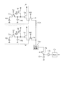
- FIG. 2 is a circuit diagram showing an example of the configuration of the light receiving unit and the vertical analog addition circuit in the imaging unit of the imaging apparatus according to the first embodiment of the present invention.
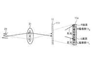
- FIG. 3 is a schematic view illustrating an outline of the pupil division phase difference method performed by the AF signal calculation unit of the imaging apparatus according to the first embodiment of the present invention.
- FIG. 4 is a diagram showing an image signal obtained by the imaging unit in the pupil division phase difference method performed by the AF signal calculation unit of the imaging apparatus according to the first embodiment of the present invention.
- FIG. 1 is a block diagram showing a functional configuration of the imaging device according to the first embodiment of the present invention.
- FIG. 2 is a circuit diagram showing an example of the configuration of the light receiving unit and the vertical analog addition circuit in the imaging unit of the imaging apparatus according to the first embodiment of the present invention.
- FIG. 3 is a schematic view illustrating an outline of the pupil division
- FIG. 5 is a schematic view illustrating an outline of another pupil division phase difference method performed by the AF signal calculation unit of the imaging device according to the first embodiment of the present invention.
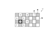
- FIG. 6 is a diagram for explaining a pixel array of the imaging unit of the imaging device according to the first embodiment of the present invention.
- FIG. 7 is a diagram for explaining a pixel interpolation method performed by the imaging unit of the imaging apparatus according to the first embodiment of the present invention.
- FIG. 8 is a diagram showing an example of the configuration of an image file generated by the image file generation unit of the imaging device according to the first embodiment of the present invention.
- FIG. 9 is a flowchart showing an outline of processing performed by the imaging device according to the first embodiment of the present invention.
- FIG. 10 is a flowchart showing an outline of the moving picture pixel readout process of FIG.
- FIG. 11 is a view schematically showing image data of pixels when RAW data imaged by the imaging device according to the first embodiment of the present invention is developed by another image processing device.
- FIG. 12 is a block diagram showing a functional configuration of the imaging device according to the second embodiment of the present invention.
- FIG. 13 is a flowchart showing an outline of processing performed by the imaging device according to the second embodiment of the present invention.
- FIG. 14 is a view showing an example of an image displayed by the display unit of the imaging device according to the second embodiment of the present invention.
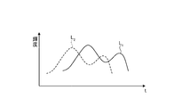
- FIG. 15 is a diagram showing an example of an image captured by HDR according to the second embodiment of the present invention.
- FIG. 16 is a diagram illustrating another example of an image captured by HDR according to the second embodiment of the present invention.
- FIG. 17 is a view showing an example of an image file generated by an image file generation unit of the imaging device according to the second embodiment of the present invention.
- FIG. 18 is a diagram schematically showing image data of pixels when RAW data imaged by the imaging device according to the second embodiment of the present invention is developed by another image processing device.
- FIG. 19 is a diagram showing an example of an image file generated by the image file generation unit of the imaging device according to the modification of the second embodiment of the present invention.
- FIG. 1 is a block diagram showing a functional configuration of the imaging device according to the first embodiment of the present invention.
- the imaging device 1 illustrated in FIG. 1 includes a main body unit 10, and an interchangeable lens unit 20 that is detachable from the main body unit 10 and that condenses light from a predetermined visual field area.
- the main body unit 10 includes an imaging unit 11, a main body communication unit 12, a clock unit 13, an operation input unit 14, a recording unit 15, a recording medium 16, a display unit 17, a touch panel 18, and a control unit 19. And.
- the imaging unit 11 is configured by an imaging element such as a CCD or a CMOS sensor.
- the imaging unit 11 is an imaging device that outputs one data from one pixel, such as an imaging device having a Bayer array, an imaging device that has a stacked light receiving unit and outputs multiple data such as RGB from one pixel It may be an element.
- the imaging unit 11 is driven under the control of the control unit 19.
- the imaging unit 11 receives the light of the subject from the interchangeable lens unit 20 via the shutter (not shown) by the light receiving surfaces of the plurality of pixels, and the electrical signal after photoelectric conversion is image data before image quality correction (RAW data Generate as).
- the imaging unit 11 performs different imaging obtained simultaneously or at different timings with the electrical signals output from the replacement pixel to be replaced.
- the image data replaced by the electric signal of the pixel is generated, and the image data is output to the control unit 19.
- the imaging unit 11 outputs, to the control unit 19, positional information (address information) regarding the positions of the replacement pixel and the imaging pixels obtained by interpolating the replacement pixel.
- the replacement pixel is a defective pixel having a defective pixel, a detection pixel when detecting the focus of the imaging device 1 (hereinafter referred to as “AF pixel”), characteristics of a light source, characteristics of a subject color, etc.
- the correction pixel is a dedicated function pixel for adjusting a shooting parameter, or a pixel corresponding to an image area determined by a shooting condition.
- the shooting parameters are exposure value, shutter speed, ISO sensitivity and white balance.
- the shooting conditions are subject depth information, subject brightness information, and subject color information.
- imaging devices have various functions, and not all pixels can be used for imaging, so pixel data not used for image formation, pixel data unsuitable for use, and pixel data other than for images Needs to be grasped at the time of imaging. Once this is known, a good image can be reproduced by correcting, substituting, or replacing. In addition, since there may be pixels which should not be used due to the problem of the photographing optical system, it is preferable to correct or substitute such pixels without using the signal as it is during reproduction.
- the imaging unit 11 includes a light receiving unit 111, a vertical analog addition circuit 112, a horizontal digital addition circuit 113, and an AF memory 114.
- the light receiving unit 111 has a plurality of pixels arranged in a matrix, receives light of an object from the interchangeable lens unit 20, performs photoelectric conversion, and outputs an electric signal.
- the vertical analog addition circuit 112 adds and reads the values of the pixels of the two rows from the light receiving unit 111, and outputs the addition pixel values of the two rows to the horizontal digital addition circuit 113.
- the horizontal digital addition circuit 113 adds the addition pixel values of two rows inputted from the vertical analog addition circuit 112 over two columns and controls the addition pixel value of four pixels as the addition pixel value at the time of moving image capturing
- the data is output to the unit 19 and is also output to the AF memory 114 and recorded as the pixel value of the AF pixel.
- FIG. 2 is a circuit diagram showing an example of the configuration of the light receiving unit 111 and the vertical analog addition circuit 112. As shown in FIG.
- the light receiving unit 111 is configured of a plurality of pixels arranged in a matrix, and FIG. 2 shows only the configuration of two pixels P (broken lines) of two rows of the same color in the light receiving unit 111.
- each pixel P is configured of a photodiode PD, a transfer transistor T1, a floating diffusion FD, a reset transistor T2, and an amplification transistor T3.
- the photodiode PD generates an electric charge in response to the received light.
- the charge generated in the photodiode PD is transferred to the floating diffusion FD by the transfer transistor T1 and accumulated.
- the reset and accumulation periods of the floating diffusion FD are set by the reset transistor T2, and a voltage based on the signal charge of the floating diffusion FD is amplified by the amplification transistor T3.
- the row selection switch T4 is turned on and off by a row selection signal, and outputs the signal current from the amplification transistor T3 to the CDS circuit 11a via the column line CA. All the row selection switches T4 in one column are connected to the common column line CA, and all the row selection switches T4 in the same row are simultaneously turned on to connect each column line CA from all the pixels P in the same row. A signal is supplied to each CDS circuit 11a via
- the row selection switch T4 is selectively turned on line by line by the vertical scanning circuit (not shown) when taking a still image.
- the row selection switch T4 of two rows of the same color for each line is turned on by the vertical scanning circuit when capturing a moving image.
- the pixel values of the pixels P of two rows of the same color are output via the column line CA at the time of moving image shooting.
- the CDS circuit 11a removes and outputs reset noise of pixel values of two rows of the same color.
- the output of the CDS circuit 11a is stored in the capacitor C1 via the transistor T5.
- a charge of the sum of pixel values of two pixels is accumulated in the capacitor C1.
- the accumulated charge of the capacitor C 1 is supplied to an analog-to-digital converter (ADC) 11 c via an amplifier 11 b to be converted into a digital signal and output to the controller 19.
- ADC analog-to-digital converter
- the addition pixel values of the pixels P of two rows of the same color are output from the ADC 11 c provided on each column line CA.
- the output of each ADC 11 c is sequentially output by a horizontal scanning circuit (not shown).
- the imaging unit 11 outputs only the added pixel value of the pixels P of the two rows of the same color at the time of moving image shooting, and can not output the pixel value of the single pixel P.
- the imaging unit 11 when the reading of the pixels P in two rows is completed by the horizontal scanning circuit at the time of moving image shooting, the pixels P in the next two rows are read. Note that each time the readout of the pixels P in two rows is completed, the pixels P in these rows are reset.
- the main body communication unit 12 is a communication interface for communicating with the interchangeable lens unit 20 mounted on the main body unit 10.
- the main body communication unit 12 also includes an electrical contact with the interchangeable lens unit 20.
- the clock unit 13 has a clocking function and a determination function of shooting date and time.
- the clock unit 13 outputs date / time data to the control unit 19 in order to add date / time data to the image data captured by the imaging unit 11.
- the operation input unit 14 has a power switch for switching the power state of the imaging apparatus 1 to the on state or the off state as a user interface for operation input, and a release switch for receiving an input of a still image release signal for giving a still image shooting instruction.
- a mode dial switch for switching various shooting modes set in the imaging device 1 an operation switch for switching various settings of the imaging device 1, a menu switch for causing the display unit 17 to display various settings of the imaging device 1, a recording medium 16
- a moving image switch for receiving an input of a moving image release signal for giving an instruction for moving image shooting.
- the release switch can be advanced and retracted by external pressure. When the release switch is pressed halfway, a 1st release signal for instructing a shooting preparation operation is input. On the other hand, when the release switch is full-pressed, a second release signal instructing still image shooting is input.
- the recording unit 15 is configured using a volatile memory and a non-volatile memory.
- the recording unit 15 temporarily records image data input from the imaging unit 11 via the control unit 19 and information being processed by the imaging device 1. Further, the recording unit 15 records various programs for operating the imaging device 1, an imaging program, various data used during execution of the program, and various parameters. Further, the recording unit 15 records a serial number for identifying the imaging device 1.
- the recording medium 16 is configured using a memory card or the like mounted from the outside of the imaging device 1.
- the recording medium 16 is detachably attached to the imaging device 1 via a memory I / F (not shown).
- a memory I / F (not shown).
- an image file for recording image data is written to the recording medium 16, or image file image data recorded on the recording medium 16 is read out.
- the image file is the image data generated by the imaging unit 11, and the electrical signals output from the replacement pixel to be replaced are different at the same time or different timings.
- the image data replaced by the electric signal of the imaging pixel and the position information on the position of the replaced pixel in the imaging unit 11 are recorded.
- the display unit 17 is configured using a display panel made of liquid crystal, organic EL (Electro Luminescence), or the like.
- the display unit 17 displays an image corresponding to the image data.
- a recview display in which the image data immediately after shooting is displayed for a predetermined time (for example, 3 seconds)
- a reproduction display in which the image data recorded in the recording medium 16 is reproduced
- the imaging unit 11 are continuous.
- a live view display that sequentially displays live view images corresponding to the image data to be generated in chronological order.
- the display unit 17 appropriately displays operation information of the imaging device 1 and information regarding imaging.
- the touch panel 18 is provided on the display screen of the display unit 17.
- the touch panel 18 detects a touch of an object from the outside, and outputs a position signal according to the detected touch position. Further, the touch panel 18 detects a position touched by the user based on the information displayed on the display unit 17, and accepts an input of an instruction signal instructing an operation to be performed by the imaging device 1 according to the detected contact position. It is also good.
- the touch panel 18 there are a resistive film method, a capacitance method, an optical method, and the like. In the first embodiment, any type of touch panel is applicable.
- the control unit 19 is configured using a CPU (Central Processing Unit) or the like.
- the control unit 19 transmits the control signal and various data to each unit constituting the imaging device 1 in accordance with an instruction signal input from the operation input unit 14 or the touch panel 18 to operate the imaging device 1. Control overall.
- the control unit 19 includes an AF signal calculation unit 191, an image processing unit 192, an image compression / decompression unit 193, an image file generation unit 194, and a recording control unit 195.
- the AF signal calculation unit 191 acquires an image signal of a pixel in a predetermined area from the image data input from the imaging unit 11, and generates an AF signal by the pupil division phase difference method based on the phase difference of the acquired image signal. Do.
- the AF signal calculation unit 191 outputs an AF signal to the interchangeable lens unit 20 via the main body communication unit 12. The details of the pupil division phase difference method by the AF signal calculation unit 191 will be described later.
- the image processing unit 192 generates processed image data obtained by performing various types of image processing including image quality correction processing on image data (RAW data) input from the imaging unit 11. Specifically, the image processing unit 192 performs at least gain processing for adjusting the brightness of the image, tone correction processing for correcting the tone, edge processing, smoothing processing, white balance processing, and color on the image data. Image processing including correction processing, noise reduction processing, ⁇ correction processing, and hue correction processing according to the shooting mode is performed to generate processed image data for display or recording.
- the image mode is a mode in which the image quality of an image to be developed is corrected according to a scene such as portrait shooting, landscape shooting, and night scene shooting.
- the image processing unit 192 functions as an image processing apparatus.
- the image compression / decompression unit 193 compresses the processed image data subjected to image processing by the image processing unit 192 according to a predetermined format, and outputs the compressed image data thus compressed to the recording medium 16.
- a predetermined format there are a JPEG (Joint Photographic Experts Group) system, a Motion JPEG system, an MP4 (H.264) system, and the like.
- the image compression / decompression unit 193 acquires image data (compressed image data) recorded in the recording medium 16, and decompresses (decompresses) the acquired image data and outputs the image data to the image file generation unit 194 or the recording unit 15. .
- the image file generation unit 194 receives positional information (addresses related to positions of image data before image quality correction (RAW data), processed image data and compressed image data, and replacement pixels in the imaging unit 11 and imaging pixels obtained by interpolating replacement pixels).
- An image file is generated in which information is recorded in association with range information indicating a range including each position, a shooting mode including the imaging device 1 and a shooting mode including the image processing parameter of the image processing unit 192.
- range information indicating a range including each position
- a shooting mode including the imaging device 1 and a shooting mode including the image processing parameter of the image processing unit 192.
- the recording control unit 195 causes the recording medium 16 to record the image file generated by the image file generation unit 194.
- the recording control unit 195 causes the image file generation unit 194 to generate an image file having contents according to an instruction signal input from the operation input unit 14 or the touch panel 18.
- the recording control unit 195 causes the image file generation unit 194 to generate an image file in which the RAW data and the photographing information are associated and recorded, and causes the recording medium 16 to record the image file.
- a communication unit or the like having a function may be further provided.
- the interchangeable lens unit 20 includes an optical system 21, a drive unit 22, a lens communication unit 23, an operation unit 24, a lens recording unit 25, and a lens control unit 26.
- the optical system 21 is configured using one or more lenses and a stop.
- the optical system 21 condenses light from a predetermined visual field area.
- the optical system 21 has an optical zoom function to change the angle of view and a focus function to change the focus.
- the drive unit 22 is configured using a DC motor or a stepping motor, and changes the focus position, the angle of view, and the like of the optical system 21 by moving the lens of the optical system 21 on the optical axis O1.
- the drive unit 22 also drives the stop of the optical system 21.
- the lens communication unit 23 is a communication interface for communicating with the main body communication unit 12 of the main body unit 10 when the interchangeable lens unit 20 is connected to the main body unit 10.
- the operation unit 24 is a ring provided around the lens barrel of the interchangeable lens unit 20, and instructs the input of an operation signal for starting the operation of the optical zoom in the optical system 21 or the adjustment of the focus position of the optical system 21. Accept an input of an instruction signal.
- the operation unit 24 may be a push switch or the like.
- the lens recording unit 25 is configured using a flash memory, and records a control program for determining the position and movement of the optical system 21, lens characteristics of the optical system 21, focal length, brightness number, and various parameters. .
- the lens control unit 26 is configured using a CPU or the like.
- the lens control unit 26 controls the operation of the interchangeable lens unit 20 according to an operation signal of the operation unit 24 or an instruction signal from the main unit 10. Specifically, the lens control unit 26 drives the drive unit 22 according to the operation signal of the operation unit 24 to focus the optical system 21, change the zoom, or change the aperture value.
- the lens control unit 26 transmits to the main body unit 10 focus position information of the interchangeable lens unit 20, focal length, and unique information for identifying the interchangeable lens unit 20. Send.
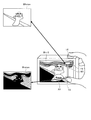
- FIG. 3 is a schematic view illustrating an outline of the pupil division phase difference method performed by the AF signal calculation unit 191. As shown in FIG. 3
- an optical image incident on the imaging device 1 from the subject Z1 via each optical path is imaged on the incident surface of the imaging element of the imaging unit 11 by the optical system 21.
- Two imaging units (for example, R imaging unit and L imaging unit) are configured as pixels for AF detection (hereinafter, referred to as AF pixels), and each light path is divided, for example, in the right direction and left direction in the exit pupil, and light from the left light (right light) from the right direction (left light) incident respectively to the R imaging unit 11 R and the L imaging unit 11 L.
- a part of the imaging unit 11 is enlarged and the R imaging unit 11 R and the L imaging unit 11 L are decentered with respect to the optical axis of the optical system 21 to make the right
- the light and the left light can be respectively incident on the R imaging unit 11 R and the L imaging unit 11 L.
- AF signal calculating unit 19 based on the phase difference between the R imaging unit 11 R, the image signal obtained by the L imaging unit 11 L L 1 and the image signals L 2, drive to drive the lens for focus adjustment
- AF signal calculating unit 191 based on the phase difference between the R imaging unit 11 R, the image signal obtained by the L imaging unit 11 L L 1 and the image signals L 2, drive to drive the lens for focus adjustment
- AF signal calculating unit 191 based on the phase difference between the R imaging unit 11 R, the image signal obtained by the L imaging unit 11 L L 1 and the image signals L 2
- the AF signal calculation unit 191 omits L pixels and uses only R pixels as AF pixels, and image signals obtained by a plurality of imaging pixels (hereinafter also referred to as N pixels) of by comparing the phase and the image signal obtained by the R imaging unit 11 R phase, it may generate a drive signal for focus adjustment.
- FIG. 6 is a diagram for explaining a pixel array of the imaging unit 11.
- the dense hatching indicates a blue pixel on which the blue filter is disposed
- the rough hatching indicates a red pixel on which the red filter is disposed
- the solid pixel is a green pixel on which the green filter is disposed.
- a frame with a border indicates an AF pixel.
- Bayer arrangement is demonstrated to an example as a pixel arrangement, even if it is honeycomb arrangement, for example, it is applicable.
- the same arrangement is repeated in units of horizontal and vertical 2 ⁇ 2 pixels. That is, blue and red pixels are disposed diagonally in the 2 ⁇ 2 pixels, and green pixels are disposed in the remaining two diagonal pixels.
- the signs A to G are for specifying a pixel
- the pixel R is an R pixel for AF detection.
- a green filter for obtaining a green pixel is disposed.
- the imaging unit 11 uses the signal read from each pixel at the time of still image shooting as it is as each pixel value of the captured image and performs pixel interpolation after imaging.
- the imaging unit 11 adds one pixel value of four pixels of the same color to generate one pixel of the color. For example, the imaging unit 11 adds green pixels D to G to generate one green pixel, and adds pixels A, B, R, and C as pixels next to the generated pixels to generate the green pixel. The same is true for other colors.
- the pixel R is not an N pixel, image quality degradation occurs if one pixel is configured using the pixels A, B, R, and C as they are. Therefore, in the first embodiment, the imaging unit 11 generates image data (RAW data) by interpolating an AF pixel with another pixel.
- FIG. 7 is a diagram for explaining a pixel interpolation method performed by the imaging unit 11.
- FIG. 7 an example in which only an R pixel is used as an AF pixel will be described.
- the imaging unit 11 when performing imaging of a moving image, the imaging unit 11 generates an image signal from the light receiving unit 111 in order to quickly perform processing of generating one pixel by pixels of two columns of two rows of the same color. Is read out by adding two rows of pixels of the same color.
- the pixel values of the pixels A to G and R are represented by A to G and R, as shown in FIGS. 7A and 7B, the addition pixel values (D + F) and (E + G) are obtained for green pixels. ,..., (A + R), (B + C),.
- addition pixel values (D + E + F + G) are obtained by performing pixel addition of two columns of the same color on the addition pixel values read from the imaging unit 11. .., (A + B + R + C),.
- the pixel R is an R pixel that outputs a pixel value based on only light incident from the right direction of the exit pupil.
- one pixel is constituted by R imaging unit 11 R and the L imaging unit 11 L, if adding the pixel value of the pixel values of the R imaging unit 11 R and the L imaging unit 11 L, Also from such AF pixels, pixel values equivalent to N pixels can be obtained. That is, assuming that not only the R imaging unit 11 R but also the L imaging unit 11 L is provided at the position of the pixel R, the pixel value of the L imaging unit 11 L is estimated, and the pixel value of the pixel R is estimated. By adding the pixel values of the L imaging unit 11 L , it is possible to obtain a pixel value when N pixels are formed at the position of the pixel R.
- the imaging unit 11 performs the above-described addition readout for high-speed processing when capturing a moving image, and reads out pixel values of a single pixel from the light receiving unit 111 when capturing a moving image. Can not. Therefore, the imaging unit 11 can not directly read the pixel value of the pixel R, and can not directly obtain a pixel value twice as large as the pixel R as the value of N pixels at the position of the pixel R. For this reason, the position of the pixel R (see FIG. 6) is the central position surrounded by the pixels D to G, and the pixel value when N pixels are formed at this position is the added pixel value (D + E + F + G Estimated to be) / 4.
- the addition pixel value (D + E + F + G) / 8 is The pixel value of the L imaging unit 11 L at the position of the pixel R is set (FIG. 7C).
- the imaging unit 11 adds the pixel values (A + B + R + C ) in addition pixel value is a pixel value of the L image pickup unit 11 L (D + E + F + G) / 8 the value obtained by adding, pixel A, B, R, all C It is set as an addition pixel value at the time of comprising N pixels (Drawing 7 (d)).
- the imaging unit 11 needs to obtain a pixel value (pixel value of the R imaging unit) in the pixel R for AF processing at the time of moving image imaging.
- the image processing unit 192 outputs the added pixel value (A + R) from the imaging unit 11.
- the pixel value of the pixel R is estimated by subtracting the pixel value of the pixel A from the added pixel value (A + R).
- the pixel value of the pixel A is estimated to be the added pixel value (D + E + F + G) / 4.
- the imaging unit 11 obtains the pixel value of the pixel R by the addition pixel value (A + R) ⁇ the addition pixel value (D + E + F + G) / 4 (FIG. 7 (e)).
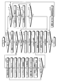
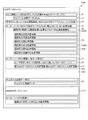
- FIG. 8 is a diagram showing an example of the configuration of an image file generated by the image file generation unit 194. As shown in FIG. 8
- An image file F100 shown in FIG. 8 is a file for recording RAW data in a format compliant with EXIF, and a header is provided similarly to EXIF, and various types of data are allocated by IFD (Image File Directory).
- the image file F100 information necessary for reproducing the main image data (main image data IFD0) and information at the time of shooting of the main image data (shooting information IFD1) are recorded in the field F1 at the beginning of the file.
- the RAW data DR is assigned to the main image data
- information at the time of shooting of the main image data is assigned information for specifying the imaging device 1 used at the time of shooting of RAW data, and information for shooting conditions.
- information corresponding to EXIF is assigned, and information such as aperture, focus distance, shutter speed, information such as image quality correction mode in image processing unit 192, image processing parameters, file name, user name, etc.
- Information defined in EXIF is assigned.
- thumbnail image data compressed by JPEG generated by the image compression / decompression unit 193 is allocated to the field F2, and information uniquely defined by the maker of the imaging device 1 (field) is allocated to the field F3.
- the Education and Manufacturing Note (IFD) is recorded. Since the first three fields F1 to F3 are created in the EXIF format, the image file F100 is formed so that the RAW data allocated to the main image data can be reproduced by various applications capable of processing the EXIF file. Ru.
- the image file F100 is assigned image processing information DS0A at the time of shooting of the main image data.
- the setting of the aperture of the imaging device 1 at the time of shooting of the RAW data DR for example, the setting of 0 EV, -1 EV, etc.
- the shutter speed, the shooting mode and the like are recorded.
- specific parameters obtained at the time of shooting are sequentially recorded.
- parameters necessary for image processing for reproducing the time of shooting are recorded as parameters, and then a reference parameter used when partially cutting out the RAW data DR (hereinafter, “cutout Various reference information is recorded.
- the aperture is recorded, for example, as 0 EV in the field F4 on the leading side, and a specific aperture value 5.6 or the like is recorded in the image processing information DS0A of the field F5 that follows.
- the image quality correction mode the auto white balance adjustment mode, the shooting mode for person shooting, etc. are recorded in the field F4 on the top side, and each color signal in this auto white balance adjustment mode is recorded in the image processing information DS0A of the field F5. And the parameters of color correction according to the shooting mode.
- various cutout reference information DS0B is set in the field F6.
- in-focus position information at the time of shooting detected from focus adjustment is recorded in the field F6.
- the in-focus position information at the time of shooting is position information of an area in focus in the image of the RAW data DR.
- the in-focus position information of the background detected in the focus search process at the time of shooting is recorded.
- Position information of the face detected at the time of shooting is recorded in the field F6.
- the control unit 19 detects an area where a face is photographed using a face template, and sets the area where the face is detected as the information of the face position.
- the imaging device 1 When the user has selected a shooting mode for shooting a person, the imaging device 1 performs focus adjustment to acquire the RAW data DR so that the area where the face is detected is in focus. In addition, when a face is not detected, that is recorded on the positional information on a face.
- the information on the backlight position is position information indicating a back light part in the imaging result, and the in-focus position in each part of the imaging result is detected at the time of the focus search.
- An area where it is determined that one object has been photographed, and an area where the in-focus position is closer to the front side and the luminance level is lower is detected, and position information of the detected area is set as information of the back light position.
- information on the saturation position is further recorded.
- the information on the saturation position is the position of the region where the luminance level is saturated by the dynamic range of the imaging device 1.
- the imaging device 1 changes the diaphragm at the time of photographing, determines the change in the luminance level of each part with respect to the change of the diaphragm, and detects a saturated region. Further, position information of the detected area is set as information of the saturation position. Further, in the image file F100, position information of the center of the optical axis at the time of shooting is recorded. Here, the position information at the center of the optical axis is set based on the information specifying the model of the lens provided in the lens. Note that, even if the backlight position information, the saturation position information, and the optical axis center position information can not detect the corresponding position information, the effect is recorded. Subsequently, various other parameters are sequentially assigned to the image file F100 to form shooting information DS0 at the time of shooting of the main image data.
- the shooting information DS1, DS2, ... of the editing process is the shooting information set in the editing process, corresponding to the image processing information DS0A for reproducing the shooting time assigned to the shooting information DS0 at the time of shooting It is set.
- history information is added to the shooting information such as the setting of the aperture, shutter speed, shooting mode, etc. assigned to the field F4 of the shooting information DS0 at the time of shooting, F7 is formed.
- the history information is information on the date and time when each piece of shooting information DS1, DS2,... Is set in the image file F100.
- specific image processing information corresponding to the imaging information assigned to the immediately preceding field F7 is recorded in the field F8.
- position information of AF pixels relating to the position of AF pixels in the light receiving unit 111 of the image pickup unit 11 and position information regarding image pickup pixels obtained by interpolating the AF pixels are recorded in the field F9.
- the image file F100 information necessary for reproducing the thumbnail image data DT is assigned following the area of the shooting information DS1, DS2,... Of this editing process, and the thumbnail image data DT is assigned to the subsequent field.
- RAW data DR which is main image data is allocated.
- the image file F100 is information corresponding to the cutout reference information (field F6) DS0B allocated to the photographing information DS0 at the time of photographing following the main image data, and the cutout reference information set at the time of the editing process is added It is made possible.
- the information to be added has the same field structure as the shooting information DS0 at the time of shooting, and history information is set in the same manner as the shooting information DS1 at the time of editing processing.
- the amount of data of the RAW data DR occupies about 95% of the total amount of data, but since this RAW data DR is allocated to the end of the file, the file head
- the thumbnail image data DT, the photographing information DS0, and the photographing information DS1 to DS2 of the editing process can be acquired by reproducing only about 5%.
- the image file generation unit 194 records the imaging result with the image file F100 according to the format illustrated in FIG. 8, RAW data DR output from the imaging unit 11 under the instruction of the recording control unit 195;
- the data of the image file F100 is generated by the photographing information DS and the thumbnail image data DT output from the recording control unit 195, the thumbnail image data DT by JPEG generated by the image compression / decompression unit 193, etc. and output to the recording medium 16 Do.
- FIG. 9 is a flowchart showing an outline of processing performed by the imaging device 1.
- the control unit 19 determines whether the imaging apparatus 1 is set to the imaging mode (step S101). When the control unit 19 determines that the imaging device 1 is set to the imaging mode (step S101: Yes), the imaging device 1 proceeds to step S102 described later. On the other hand, when the control unit 19 determines that the imaging device 1 is not set to the imaging mode (step S101: No), the imaging device 1 proceeds to step S122 described later.
- step S102 the control unit 19 causes the imaging unit 11 to perform imaging and causes the display unit 17 to display a live view image corresponding to the image data input from the imaging unit 11.
- the image processing unit 192 applies thinning processing to the image data from the imaging unit 11 according to the number of display pixels of the display unit 17, and then outputs the image data to the display unit 17.
- step S103 when an instruction signal instructing moving image shooting is input from the operation input unit 14 (step S103: Yes), the imaging device 1 reads out moving image pixel readout simultaneously read every two lines from the imaging unit 11 at the time of moving image shooting. A process is performed (step S104).
- FIG. 10 is a flowchart showing an outline of the moving image pixel readout process.
- the imaging unit 11 initializes variables L, M, and N for performing the calculation shown in FIG. 7 described above to 0 (step S201).
- the imaging unit 11 causes the vertical analog addition circuit 112 to add two pixels in two rows skipped in one row (step S202).
- the addition pixel values (D + F) of the green pixels D and F in FIG. 6 and the addition pixel values (E + G) of the pixels E and G are obtained.
- step S203 When two pixels in two rows are not two pixels including AF pixels (step S203: No), when the processing of all the columns of the light receiving unit 111 is not completed (step S206: No), the imaging unit 11 receives light The row of the unit 111 is changed (step S207), and the process returns to step S202. On the other hand, when the processing of all the lines of the light receiving unit 111 is completed (step S206: Yes), the imaging unit 11 proceeds to step S208.
- the imaging unit 11 adds four pixels skipped in one column by the horizontal digital addition circuit 113 (step S208). Thereby, for example, the addition pixel value (D + F) and the addition pixel value (E + G) are added.
- step S209 Yes
- the imaging unit 11 increments the variable M (step S210)
- the added pixel value S2 (M) (D + E + F + G) is stored in the AF memory 114.
- Temporary recording step S211.
- the addition pixel values of all four pixels surrounding the AF pixel are stored in the AF memory 114.
- step S209 If the four pixels added do not surround the AF pixel (step S209: No), the imaging unit 11 proceeds to step S212.
- step S212 when the added four pixels include an AF pixel (step S212: Yes), the imaging unit 11 increments the variable N (step S213), and the addition result (A + B + R + C) of four pixels is added to the added pixel value S3 (N ) (Step S214).
- the imaging unit 11 adds S2 (M) / 8 to S3 (N) (for example, obtains an added pixel value on the right side of FIG. 7 (see d (step S215).) After step S215, the imaging unit 11 proceeds to step S216.
- step S212 when the added four pixels do not include AF pixels (step S212: No), the imaging unit 11 proceeds to step S216.
- step S216: Yes when all the lines of the light receiving unit 111 are finished (step S216: Yes), the imaging device 1 returns to the main routine of FIG. On the other hand, when all the lines of the light receiving unit 111 are not finished (step S216: No), the imaging unit 11 changes the line of the light receiving unit 111 (step S217), and returns to step S202.
- step S105 the control unit 19 sets the addition pixel value S2 (J) of 4 pixels to 1 ⁇ 4 when the pixel surrounded by 4 pixels of the same color is an AF pixel, thereby setting the AF pixel to N pixels.
- the pixel value N (J) in the configured case is estimated.
- the AF signal calculation unit 191 subtracts the pixel value N (J) when the R pixel is formed of N pixels from the addition value S1 (J of two pixels including the R pixel (see FIG. e) Refer to step S106) and estimate the pixel value R (J) of the R pixel.
- the AF signal calculation unit 191 subtracts the pixel value R (J) when the AF pixel is configured by the R pixel from the pixel value N (J) when the AF pixel is configured by the N pixel, A pixel value L (J) is estimated when the AF pixel is formed of L pixels (step S107).
- the AF signal calculation unit 191 detects the correlation between the image signal obtained by the plurality of pixel values R (J) estimated and the image signal obtained by the plurality of pixel values L (J) estimated (step S108).
- the correlation between the image signal obtained by the plurality of estimated pixel values R (J) and the image signal obtained by the plurality of estimated pixel values N (J) is detected (step S109).
- the lens control unit 26 drives the drive unit 22 based on the AF signal input from the AF signal calculation unit 191 to perform focusing of the optical system 21 on the side of higher correlation (step S110).
- the AF signal calculation unit 191 adopts a combination that can obtain high correlation for phase difference detection for focusing. For example, when the correlation between the image signal obtained by the pixel value R (J) and the image signal obtained by the plurality of pixel values L (J) is higher, the AF signal calculation unit 191 sets the pixel value R (J Detects the phase difference between the image signal obtained by (a) and the image signal obtained by the plurality of pixel values L (J), and generates an AF signal for driving and controlling the interchangeable lens unit 20 based on the detected phase difference. Then, the data is output to the lens control unit 26. The AF signal is output to the lens control unit 26, and the lens control unit 26 drives the drive unit 22 to focus the optical system 21.
- the image processing unit 192 generates an image at the time of capturing a moving image by using the acquired 4-addition pixel value after focusing which is color data information for each acquired coordinate, performs predetermined image processing, and then performs processing.
- An image corresponding to the image data is displayed on the display unit 17 (step S111).
- the image compression / decompression unit 193 performs encoding processing on the processed image data generated by the image processing unit 192, and then causes the recording unit 15 to record the processed image data (step S111).
- step S112: Yes the imaging device 1 proceeds to step S117 described later.
- step S112: No the imaging device 1 returns to step S105 and continues moving image shooting.
- step S103 when there is no instruction signal instructing moving image shooting from operation input unit 14 (step S103: No), when an instruction signal instructing still image shooting is input (step S113: Yes), imaging device 1 Executes AF processing for automatically adjusting the focus (step S114), and executes still image shooting (step S115).
- the control unit 19 records the image data (RAW data DR) input from the imaging unit 11 in the recording unit 15.
- the image processing unit 192 acquires image data from the recording unit 15, and performs image processing including interpolation of AF pixels on the acquired image data to generate processed image data (step S116).
- the image file generation unit 194 performs position information of AF pixels regarding the position of AF pixels in the imaging unit 11 in which the image processing unit 192 performs interpolation processing on the RAW data DR and the processed image data recorded in the recording unit 15; And an image file in which positional information of replacement pixels relating to the position of the imaging pixel for interpolating the AF pixel is associated and generated (step S117), and the generated image file is recorded on the recording medium 16 (step S118) .
- the imaging device 1 generates high-speed image data in order to correspond to the live view image, but by recording as RAW data DR, another image processing device, for example, When developing the RAW data DR by the computer, using the position information of the AF pixel and the position information of the image pickup pixel substituted for the AF pixel, a more natural and accurate interpolation or replacement or composition image is generated be able to.
- the image file generation unit 194 generates an image file by associating the moving image data recorded in the recording unit 15 with the positional information on AF pixels and the information on interpolation pixels, as in the case of still image shooting.
- control unit 19 causes the display unit 17 to display an image corresponding to the recorded processed image data on the recording unit 17 (step S119).
- step S120: Yes the imaging apparatus 1 ends the present process.
- step S120: No the imaging device 1 proceeds to step S121.
- control unit 19 receives an operation to change the mode of the imaging device 1 to the imaging mode or the reproduction mode (step S121). After step S121, the imaging device 1 returns to step S101.
- step S113 when the instruction signal for instructing still image shooting is not input via the operation input unit 14 (step S113: No), the imaging device 1 proceeds to step S120.
- step S101: No the case where the imaging apparatus 1 is not set to the imaging mode (step S101: No) will be described.
- the control unit 19 causes the display unit 17 to display a list of image files recorded in the recording medium 16 (step S123). .
- the control unit 19 causes the display unit 17 to display a list of thumbnail images corresponding to the image data included in the image file.
- step S124 When an image file is selected (step S124: Yes), the control unit 19 causes the display unit 17 to reproduce an image corresponding to the image data of the selected image file (step S125). At this time, the image processing unit 192 develops the image data by performing image processing using the RAW data DR recorded in the image file and the position information of the interpolation pixel. Thus, in the first embodiment, the image processing unit 192 functions as an image processing apparatus. Thereafter, the imaging device 1 returns to step S122.
- step S124 when the image file is not selected within a predetermined time (for example, 3 seconds) (step S124: No), the imaging device 1 proceeds to step S126.
- a predetermined time for example, 3 seconds
- step S126: Yes when an instruction signal for ending the reproduction mode is input from the operation input unit 14 (step S126: Yes), the imaging device 1 proceeds to step S120. On the other hand, when the instruction signal for ending the reproduction mode is not input through the operation input unit 14 (step S126: No), the imaging device 1 returns to step S123.
- step S122 when the imaging device 1 is not set to the reproduction mode (step S122: No), the imaging device 1 returns to step S101.
- the image file before the image quality correction generated by the image pickup unit 11 by the image file generation unit 194 and the image pickup pixels obtained by interpolating the AF pixels and the interpolation pixels in the image pickup unit 11 (N Since the image file F100 is generated in which the positional information on each position is associated with each other and recorded, the image can be developed with high image quality in the post-processing for performing the image quality correction processing for display on the RAW data DR. .
- the first embodiment even if pixel values of a plurality of pixels are added after being output from the imaging unit 11 having AF pixels for high-speed processing at the time of moving images, simple arithmetic processing Thus, it is possible to estimate the addition pixel value when the AF pixel is a normal pixel, and to obtain a high quality moving image. Also in this case, the pixel value of the AF pixel can be acquired by a simple calculation process, and focusing can be performed with high accuracy.
- simple arithmetic processing is simple arithmetic operation on the stored addition result, each storing the addition result depending on whether the plurality of pixels to be added are pixels including AF pixels or pixels surrounding AF pixels. To perform high-speed processing.
- the image processing unit 192 performs image quality correction processing of the RAW data DR based on the position information of the AF pixel and the position information of the imaging pixel obtained by interpolating the AF pixel. Although it has been generated, for example, even an extracted pixel extracted in edge extraction can be applied. In this case, the image processing unit 192 can develop an image with higher image quality by reducing the weight of the interpolation pixel based on the position information of the extraction pixel and gazing at the pixels around it. Furthermore, in the general noise reduction processing, the flat portion and the edge portion are determined, but the determination standard at that time can also be changed according to the position information of the extracted pixel. As a result, unnecessary image quality deterioration due to noise reduction processing by the image processing unit 192 can be prevented.
- pixels having L imaging units 11 L and R imaging units 11 R that receive light from horizontal and horizontal directions are used as AF pixels. It is apparent that the same can be applied to an example using a pixel having two imaging units that receive light of.
- image data before image quality correction is recorded as RAW data
- image data obtained by interpolating replacement pixels may be recorded as RAW data, or may be recorded before image quality correction (before image quality correction).
- the data of replacement pixels may be separately recorded in an image file.
- any one can be selected whether or not the image quality correction process for display is performed on the RAW data DR. If image quality equivalent to that of an imaging device can be realized by performing correction, substitution, or replacement by various methods, and if there is a post-processing that separately performs image quality correction processing for display, higher quality can be obtained by using these information. It can be developed with image quality.
- only the pixel data has been described for replacement, but it is possible not only to replace with other pixels, but also to correct by analogy from the pattern of the image. ing.
- the focus pixel (AF pixel) is corrected, an example of embedding the exposure adjustment pixel in the image pickup device, a pixel for controlling the light amount of a strobe, and a pixel for correcting the exposure as described later
- the pixel is embedded in the same way as the present embodiment, and the pixel is not the pixel or the pixel data for the image for photographing or reproduction display, and this is not used as it is. It becomes. Therefore, it is important to provide the file with information indicating the location of the pixel in the later steps when handling this. Not only that, but information on what kind of replacement and correction should be made may be included in the file. For example, replacement rules as shown in FIG.
- the imaging apparatus according to the second embodiment is different in configuration from the imaging apparatus according to the above-described first embodiment. Therefore, in the second embodiment, after the configuration of the imaging apparatus is described, processing performed by the imaging apparatus according to the second embodiment will be described. In the following, the same components as those of the first embodiment described above will be described with the same reference numerals.
- FIG. 12 is a block diagram showing a functional configuration of the imaging device according to the second embodiment of the present invention.
- An imaging device 200 illustrated in FIG. 12 includes a main body unit 210 and an interchangeable lens unit 20.
- the main body unit 210 includes an imaging unit 11, a main body communication unit 12, a clock unit 13, an operation input unit 14, a recording unit 15, a recording medium 16, a display unit 17, a touch panel 18, and a subject analysis unit 211. , And a control unit 212.
- the subject analysis unit 211 analyzes the pixel area of the imaging unit 11 to be interpolated based on the image data generated by the imaging unit 11 via the control unit 212. Specifically, the subject analysis unit 211 determines the brightness and the exposure state of the subject based on the luminance information included in the image data, for example, the exposure value limit state (overexposure), the underexposure state (underexposure) or the appropriate exposure state Are analyzed, and the analysis result is output to the control unit 212.
- the control unit 212 is configured using a CPU or the like.
- the control unit 212 transfers the control signal and various data to each unit constituting the imaging device 200 in accordance with an instruction signal input from the operation input unit 14 or the touch panel 18 to operate the imaging device 200. Control overall.
- the control unit 212 includes an AF signal calculation unit 191, an image processing unit 192, an image compression / decompression unit 193, an image file generation unit 194, a recording control unit 195, and an image combining unit 213.
- the image combining unit 213 expands the dynamic range based on the analysis result of the subject analysis unit 211 and the image data input from the imaging unit 11 when the imaging device 200 performs imaging in the HDR (High Dynamic Range) imaging mode.
- image data Specifically, in the image combining unit 213, two image data input from the imaging unit 11, for example, image data in which the dynamic lens is saturated in some pixels (exposure over image) and noise in some pixels Image data adjusted with a dynamic lens is generated by replacing a pixel in which noise is occurring or a saturated pixel with another pixel using the generated image data (under-exposure image).
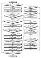
- FIG. 13 is a flowchart showing an outline of processing performed by the imaging device 200.
- step S301 when the imaging device 200 is set to the imaging mode (step S301: Yes), the control unit 212 communicates with the interchangeable lens unit 20 via the main unit communication unit 12 and the lens communication unit 23. (Step S302).
- control unit 212 causes the imaging unit 11 to perform imaging and causes the display unit 17 to display a live view image corresponding to the image data input from the imaging unit 11 (step S303).
- image processing unit 192 applies thinning processing to the image data from the imaging unit 11 according to the number of display pixels of the display unit 17, and then outputs the image data to the display unit 17.
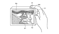
- the control unit 212 determines whether the slide touch or the release switch of the operation input unit 14 has been half-pressed from the outside of the screen of the display unit 17 (step S304). Specifically, the control unit 212 detects a touch position from the outside of the screen of the display unit 17 from the touch panel 18, and determines whether the touch position changes with time, thereby performing slide touch. Decide whether or not.
- the imaging device 200 proceeds to step S305 described later.
- step S304 determines that the slide touch or the release switch of the operation input unit 14 is not half-pressed from the outside of the screen of the display unit 17 (step S304: No).
- the imaging device 200 will be described later. It transfers to step S312.
- the HDR bar M1 displays, for example, a bar position upper end icon Y1 for receiving an input of an instruction signal for instructing image data on the overexposure side, and a bar position lower end icon Y2 for receiving input of an instruction signal for instructing image data on the underexposure side. Be done.
- Step S306 when the bar position upper end icon Y1 is slide-operated via the touch panel 18 (step S306: Yes), the image data on the + side is used as a reference of the composite image, and the exposure amount is increased or decreased according to the slide movement distance.
- Step S307 The composite image of HDR is displayed on the display unit 17 (step S308).
- the image combining unit 213 sets the exposure amount of the image W h1 and the image W u1 to be combined with each other according to the movement distance of the slide, using the image W h1 on the + side as the reference of the combined image.
- the composite image W n + 1 is generated by increasing or decreasing as appropriate.
- the imaging device 200 proceeds to step S312 described later.
- step S306 When the bar position upper end icon Y1 is not slide operated through the touch panel 18 (step S306: No), when the bar position lower end icon Y2 is slide operated through the touch panel 18 (step S309: Yes), the-side The exposure amount is increased or decreased according to the movement distance of the slide by using the image data of B as the reference of the combined image (step S310), and the combined image of HDR is displayed on the display unit 17 (step S311).
- the image combining unit 213 sets the exposure amounts of the image W hmax and the image W umax to be combined with each other according to the movement distance of the slide, using the image W umax on the ⁇ side as the reference of the combined image.
- the composite image W n + 2 is generated by increasing or decreasing the ratio as appropriate.
- step S311 the imaging device 200 proceeds to step S312 described later.
- step S309 when the bar position lower end icon Y2 is not slide-operated via the touch panel 18 (step S309: No), the imaging device 200 proceeds to step S312.
- step S312 determines whether there is no touch operation.
- step S312 determines whether there is no touch operation after the display unit 17 displays the live view image.
- step S312 determines that there is no touch operation after the display unit 17 displays the live view image.
- step S313 the image combining unit 213 combines two pieces of image data adjusted in ⁇ 2 steps from the image data of the proper exposure to generate a combined image.
- the image combining unit 213 may combine three pieces of the image data of the proper exposure, the image data of the -2 step exposure, and the image data of the +2 step exposure to generate a combined image.
- step S314: Yes The unit 212 deletes the HDR bar M1 from the live view image of the display unit 17 (step S315). After step S315, the imaging device 200 proceeds to step S316.
- the imaging apparatus 200 executes AE ⁇ AF processing (step S316).
- step S317 Yes
- the imaging device 200 executes still image shooting (step S318).
- the control unit 212 records the two image data (RAW data DR) input from the imaging unit 11 in the recording unit 15.
- the image file generation unit 194 generates HDR image RAW data of the two pre-correction image data (RAW data DR) recorded in the recording unit 15 and the HDR image generated by the image synthesis unit 213 as the RAW data DR.
- RAW data pixels are added to each other to generate an image file in which position information of interpolated pixels is associated and recorded (step S319).
- the image file generation unit 194 generates an image file.
- the image file F200 two RAW data (first RAW data, second RAW data) before correction and HDR image data are stored in the field F9. Further, in the field F9, position information regarding the position of a pixel obtained by adding and replacing pixels in the HDR image RAW data is recorded.
- the image file generation unit 194 records the generated image file on the recording medium 16 (step S320).
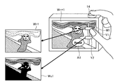
- the imaging device 200 generates high-speed image data in order to correspond to the live view image, but by recording as RAW data DR, another image processing device, for example,
- RAW data DR another image processing device
- more natural and accurate replacement, composition, and correction can be performed by using the position information of replacement pixels ((FIG. 18A to FIG. 18C)) And so on to generate an HDR image (Fig. 18 (d)).
- step S321: Yes the imaging device 200 ends the present process.
- step S321: No the imaging device 1 returns to step S301.
- step S301 when the imaging device 200 is not set to the photographing mode (step S301: No), when the imaging device 200 is set to the reproduction mode (step S322: Yes), the control unit 212 records the recording medium
- the display unit 17 reproduces the image data of the image file recorded in 16 (step S323).
- the image processing unit 192 may generate an HDR image based on the two RAW data stored in the image file and the position information of the replacement pixel.
- the HDR image taken can be generated (see, for example, FIG. 18).
- step S324: Yes when the image is changed via the operation input unit 14 (step S324: Yes), the control unit 212 changes the image file to the next image file to be recorded by the recording medium 16 (step S325). , And move on to step S321.
- step S324: No when the image is not changed via the operation input unit 14 (step S324: No), the imaging device 1 proceeds to step S321.
- step S322 when the imaging device 200 is not set to the reproduction mode (step S322: No), the imaging device 200 proceeds to step S321.
- the image file before the image quality correction generated by the image pickup unit 11 by the image file generation unit 194 and the other pixels in which the correction pixel and the correction pixel by image processing in the image pickup unit 11 are replaced Since the image file F 200 is generated in which positional information on the positions of the imaging pixels is associated with each other, development can be performed with high image quality when image quality correction processing for display is performed on the RAW data DR.
- the first RAW data and the second RAW data are recorded in one image file, but as shown in FIG. 19, for example, the images of the first RAW data and the second RAW data in the recording medium 16
- the specification information of the file may be recorded in association with the image file F 300 in which the RAW data DR of HDR is recorded. Thereby, the capacity of one image file can be reduced.
- the image file F200 is generated in which the correction pixel by the image processing in the image pickup unit 11 is associated with the position information related to the position of each of the other imaging pixels replacing the correction pixel.
- Data indicating the previous necessary image portion may be recorded as RAW data, or data indicating an image portion corrected after image quality correction (data representing a pixel) may be recorded as RAW data .
- data indicating an area may be separately recorded in an image file. In this way, if only the corrected part and the part requiring correction are recorded, correction of the image quality of that part, substitution of the image, and data replacement can be performed by various methods, and image quality different from that of the imaging device can be realized. Become.
- the second embodiment has been described by replacing pixel data, it is possible not only to replace by other pixels, but also to correct by analogy from the pattern of the image, and to include such cases as well.
- the image portion for HDR is corrected here, other image portions that need to be replaced may be recorded so as to be correctable.
- the pixel is not pixel data that can be used as it is for photographing and reproduction images, and the above-described correction, substitution, and replacement processing are required. Therefore, it is important to provide the file with information indicating the location of the pixel in the later steps when handling this. Not only that, but information on what kind of replacement and correction should be made may be included in the file. Information on replacement rules or replacement pixels may be provided.
- the present invention can be carried out even with an image reproduction device that performs image reproduction of an image file for recording image data.
- the image generation device is an acquisition step of acquiring replacement target pixel information regarding a position of a replacement pixel which is a pixel constituting an image corresponding to image data and has been replaced by another pixel;
- the identification step of identifying a replacement pixel from a plurality of electrical signals respectively output from a plurality of pixels constituting an image corresponding to the image data based on the acquired replacement target pixel information, and the replacement pixel identified in the identification step
- a generation step of generating interpolation image data by interpolating with a plurality of electric signals respectively output from a plurality of images, and a reproduction step of reproducing the interpolation image data generated in the generation step are executed.
- the image generation device is an information processing device including an imaging device, a portable device including a smartphone, an electronic device such as a tablet type portable device, a head mounted display, and a display monitor such as a PC.
- the image processing unit is incorporated in the control unit, but an image processing unit may be separately provided, for example. Furthermore, a plurality of image processing units (image engines) may be provided.
- the image processing unit is incorporated in the imaging device as an image processing apparatus, but an image processing unit may be separately provided.
- the image file is recorded in the recording medium, but it may be output to another image processing apparatus, for example, an electronic apparatus such as a mobile phone or an image processing apparatus equipped with an image processing unit via the Internet. You may
- the image pickup apparatus is also applicable to electronic devices such as a digital video camera to which an accessory etc. can be attached and a portable telephone or tablet type portable device having a photographing function. It can apply.
- the program to be executed by the imaging device and the image processing device according to the present invention is file data of an installable format or an executable format, and is a CD-ROM, a flexible disk (FD), a CD-R, a DVD (Digital Versatile Disk). ), A USB medium, a flash memory, etc., and provided by being recorded on a computer readable recording medium.
- the program to be executed by the imaging device and the image processing device according to the present invention may be stored on a computer connected to a network such as the Internet and provided by being downloaded via the network. Furthermore, the program to be executed by the imaging device and the image processing device according to the present invention may be provided or distributed via a network such as the Internet.
- Imaging apparatus 10 210 main body 11 imaging section 12 main body communication section 13 clock section 14 operation input section 15 recording section 16 recording medium 17 display section 18 touch panel 19, 212 control section 20 interchangeable lens section 21 optical system 22 drive section Reference Signs List 23 lens communication unit 24 operation unit 25 lens recording unit 26 lens control unit 111 light receiving unit 112 vertical analog addition circuit 113 horizontal digital addition circuit 114 memory for AF 191 AF signal calculation unit 192 image processing unit 193 image compression / decompression unit 194 image file generation Part 195 Recording control part 211 Subject analysis part 213 Image composition part
Landscapes
- Engineering & Computer Science (AREA)
- Multimedia (AREA)
- Signal Processing (AREA)
- Human Computer Interaction (AREA)
- Physics & Mathematics (AREA)
- Spectroscopy & Molecular Physics (AREA)
- Studio Devices (AREA)
- Television Signal Processing For Recording (AREA)
- Editing Of Facsimile Originals (AREA)
- Image Processing (AREA)
Abstract
L'invention porte sur un dispositif d'imagerie permettant de développer des données brutes à une plus haute qualité d'image, un dispositif de traitement d'image, un support d'enregistrement qui enregistre des fichiers d'image, un procédé d'enregistrement, un procédé de reproduction d'image et un programme. Le dispositif d'imagerie comprend : une unité d'imagerie (11) qui génère des données d'image ayant des signaux électriques, qui sont délivrés par des pixels de remplacement qui doivent être remplacés et font partie d'une pluralité de signaux électriques délivrés par chaque pixel d'une pluralité de pixels, remplacés par des signaux électriques pour différents pixels d'imagerie obtenus au même moment ou à un moment différent ; et une unité de génération de fichier d'image (194) qui génère des fichiers d'image qui associent et enregistrent des données d'image générées par l'unité d'imagerie (1) et des informations de position concernant la position des pixels de remplacement dans l'unité d'imagerie (11).
Priority Applications (4)
| Application Number | Priority Date | Filing Date | Title |
|---|---|---|---|
| JP2013544923A JP6184869B2 (ja) | 2012-05-31 | 2013-03-13 | 撮像装置、画像処理装置、画像ファイルを記録した記録媒体、記録方法、画像再生方法およびプログラム |
| CN201380027680.XA CN104365082B (zh) | 2012-05-31 | 2013-03-13 | 摄像装置、图像处理装置、以及记录方法 |
| EP13797232.9A EP2860958B1 (fr) | 2012-05-31 | 2013-03-13 | Dispositif d'imagerie, support d'enregistrement enregistrant des fichiers d'image, procédé d'enregistrement et programme |
| US14/551,391 US9426392B2 (en) | 2012-05-31 | 2014-11-24 | Imaging device, image processing device, recording medium in which image file is recorded, recording method, image playback method, and computer-readable recording medium |
Applications Claiming Priority (2)
| Application Number | Priority Date | Filing Date | Title |
|---|---|---|---|
| JP2012-125410 | 2012-05-31 | ||
| JP2012125410 | 2012-05-31 |
Related Child Applications (1)
| Application Number | Title | Priority Date | Filing Date |
|---|---|---|---|
| US14/551,391 Continuation US9426392B2 (en) | 2012-05-31 | 2014-11-24 | Imaging device, image processing device, recording medium in which image file is recorded, recording method, image playback method, and computer-readable recording medium |
Publications (1)
| Publication Number | Publication Date |
|---|---|
| WO2013179725A1 true WO2013179725A1 (fr) | 2013-12-05 |
Family
ID=49672933
Family Applications (1)
| Application Number | Title | Priority Date | Filing Date |
|---|---|---|---|
| PCT/JP2013/057072 WO2013179725A1 (fr) | 2012-05-31 | 2013-03-13 | Dispositif d'imagerie, dispositif de traitement d'image, support d'enregistrement enregistrant des fichiers d'image, procédé d'enregistrement, procédé de reproduction d'image et programme |
Country Status (5)
| Country | Link |
|---|---|
| US (1) | US9426392B2 (fr) |
| EP (1) | EP2860958B1 (fr) |
| JP (2) | JP6184869B2 (fr) |
| CN (2) | CN108259757A (fr) |
| WO (1) | WO2013179725A1 (fr) |
Families Citing this family (18)
| Publication number | Priority date | Publication date | Assignee | Title |
|---|---|---|---|---|
| JP5967991B2 (ja) * | 2012-03-16 | 2016-08-10 | キヤノン株式会社 | 撮像装置及びその制御方法、並びにプログラム |
| US9509919B2 (en) * | 2014-11-17 | 2016-11-29 | Duelight Llc | System and method for generating a digital image |
| JP2015169722A (ja) * | 2014-03-05 | 2015-09-28 | ソニー株式会社 | 撮像装置 |
| JP6444073B2 (ja) * | 2014-06-25 | 2018-12-26 | キヤノン株式会社 | 画像処理装置 |
| KR20160071203A (ko) * | 2014-12-11 | 2016-06-21 | 삼성전자주식회사 | 이미지 신호 프로세서, 이의 작동 방법, 및 이를 포함하는 모바일 컴퓨팅 장치 |
| US10003814B2 (en) * | 2015-05-06 | 2018-06-19 | Mediatek Inc. | Image processor, display image processing method and associated electronic device |
| JP6738251B2 (ja) * | 2016-09-09 | 2020-08-12 | キヤノン株式会社 | 撮像装置及びその制御方法、プログラム、記憶媒体 |
| JP2018107664A (ja) * | 2016-12-27 | 2018-07-05 | キヤノン株式会社 | 画像処理装置および画像処理方法、撮像装置、プログラム |
| US10158797B2 (en) * | 2017-03-31 | 2018-12-18 | Motorola Mobility Llc | Combining images when a face is present |
| KR102434417B1 (ko) * | 2017-07-20 | 2022-08-22 | 삼성전자주식회사 | 이미지 데이터 및 이미지 촬영의 제어와 관련된 데이터의 크기에 기반하여, 이미지 데이터 및 이미지 촬영의 제어와 관련된 데이터를 전송하는 방법 및 이를 지원하는 전자 장치 |
| CN107835362B (zh) * | 2017-10-30 | 2019-12-31 | Oppo广东移动通信有限公司 | 图像存储方法、图像显示方法及电子设备 |
| CN111147739A (zh) * | 2018-03-27 | 2020-05-12 | 华为技术有限公司 | 拍照方法、拍照装置和移动终端 |
| WO2019194307A1 (fr) * | 2018-04-06 | 2019-10-10 | 株式会社ニコン | Dispositif d'imagerie et système de transmission/enregistrement d'image |
| US11133339B2 (en) * | 2018-04-16 | 2021-09-28 | Canon Kabushiki Kaisha | Image sensor, image capturing apparatus and image processing apparatus |
| JP7187190B2 (ja) * | 2018-06-29 | 2022-12-12 | キヤノン株式会社 | 電子機器、および電子機器の制御方法、プログラム、記憶媒体 |
| JP7263053B2 (ja) | 2019-02-28 | 2023-04-24 | キヤノン株式会社 | 撮像装置、画像処理装置、それらの制御方法、プログラム |
| US11533439B2 (en) * | 2020-05-29 | 2022-12-20 | Sanjeev Kumar Singh | Multi capture settings of multi light parameters for automatically capturing multiple exposures in digital camera and method |
| CN114143515A (zh) * | 2021-11-30 | 2022-03-04 | 维沃移动通信有限公司 | 图像传感器、摄像模组和电子设备 |
Citations (3)
| Publication number | Priority date | Publication date | Assignee | Title |
|---|---|---|---|---|
| JPH10285541A (ja) * | 1997-04-09 | 1998-10-23 | Asahi Optical Co Ltd | 電子スチルカメラの画像補正情報記録装置および画像復元処理装置 |
| JP2007334708A (ja) | 2006-06-16 | 2007-12-27 | Sony Corp | 画像処理装置、画像処理方法、画像処理方法のプログラム、画像処理方法のプログラムを記録した記録媒体 |
| JP2009105681A (ja) * | 2007-10-23 | 2009-05-14 | Canon Inc | 画像処理装置及び画像処理プログラム |
Family Cites Families (15)
| Publication number | Priority date | Publication date | Assignee | Title |
|---|---|---|---|---|
| JPS5810032A (ja) * | 1981-07-09 | 1983-01-20 | オリンパス光学工業株式会社 | 内視鏡 |
| JP2749849B2 (ja) * | 1988-12-27 | 1998-05-13 | キヤノン株式会社 | 撮像装置 |
| US5309243A (en) * | 1992-06-10 | 1994-05-03 | Eastman Kodak Company | Method and apparatus for extending the dynamic range of an electronic imaging system |
| JP4511066B2 (ja) * | 2001-03-12 | 2010-07-28 | オリンパス株式会社 | 撮像装置 |
| US7738533B2 (en) * | 2002-01-07 | 2010-06-15 | Qualcomm Incorporated | Multiplexed CDMA and GPS searching |
| JP4027253B2 (ja) * | 2003-03-27 | 2007-12-26 | 富士フイルム株式会社 | 撮像装置 |
| EP3310037A1 (fr) * | 2004-10-26 | 2018-04-18 | Nikon Corporation | Camera numerique et dispositif de combinaison d' images |
| JP4389766B2 (ja) * | 2004-11-22 | 2009-12-24 | セイコーエプソン株式会社 | 撮像装置 |
| JP2008205530A (ja) * | 2007-02-16 | 2008-09-04 | Seiko Epson Corp | 撮像装置、撮像システム及び撮像方法 |
| JP4940086B2 (ja) * | 2007-10-03 | 2012-05-30 | キヤノン株式会社 | 色処理装置およびその方法 |
| JP5462560B2 (ja) * | 2009-09-08 | 2014-04-02 | キヤノン株式会社 | 画像処理装置 |
| WO2011122914A2 (fr) * | 2010-04-02 | 2011-10-06 | 삼성전자 주식회사 | Procédé et appareil d'envoi de contenu de radiodiffusion numérique pour fournir du contenu bidimensionnel et tridimensionnel, et procédé et appareil de réception de contenu de radiodiffusion numérique |
| JP2012050073A (ja) * | 2010-07-30 | 2012-03-08 | Nikon Corp | 撮像装置及び画像合成プログラム |
| CN103119948A (zh) * | 2010-09-19 | 2013-05-22 | Lg电子株式会社 | 用于处理针对3d(三维)广播业务的广播信号的方法和装置 |
| JP5656561B2 (ja) * | 2010-10-28 | 2015-01-21 | キヤノン株式会社 | 画像処理装置、その制御方法、および制御プログラム |
-
2013
- 2013-03-13 CN CN201810212426.1A patent/CN108259757A/zh active Pending
- 2013-03-13 JP JP2013544923A patent/JP6184869B2/ja active Active
- 2013-03-13 WO PCT/JP2013/057072 patent/WO2013179725A1/fr active Application Filing
- 2013-03-13 EP EP13797232.9A patent/EP2860958B1/fr active Active
- 2013-03-13 CN CN201380027680.XA patent/CN104365082B/zh active Active
-
2014
- 2014-11-24 US US14/551,391 patent/US9426392B2/en active Active
-
2017
- 2017-07-24 JP JP2017143046A patent/JP2017195003A/ja active Pending
Patent Citations (3)
| Publication number | Priority date | Publication date | Assignee | Title |
|---|---|---|---|---|
| JPH10285541A (ja) * | 1997-04-09 | 1998-10-23 | Asahi Optical Co Ltd | 電子スチルカメラの画像補正情報記録装置および画像復元処理装置 |
| JP2007334708A (ja) | 2006-06-16 | 2007-12-27 | Sony Corp | 画像処理装置、画像処理方法、画像処理方法のプログラム、画像処理方法のプログラムを記録した記録媒体 |
| JP2009105681A (ja) * | 2007-10-23 | 2009-05-14 | Canon Inc | 画像処理装置及び画像処理プログラム |
Non-Patent Citations (1)
| Title |
|---|
| See also references of EP2860958A4 |
Also Published As
| Publication number | Publication date |
|---|---|
| CN104365082A (zh) | 2015-02-18 |
| JP2017195003A (ja) | 2017-10-26 |
| CN108259757A (zh) | 2018-07-06 |
| US20150077603A1 (en) | 2015-03-19 |
| EP2860958A4 (fr) | 2016-04-13 |
| EP2860958A1 (fr) | 2015-04-15 |
| CN104365082B (zh) | 2018-04-10 |
| EP2860958B1 (fr) | 2019-08-07 |
| US9426392B2 (en) | 2016-08-23 |
| JP6184869B2 (ja) | 2017-08-23 |
| JPWO2013179725A1 (ja) | 2016-01-18 |
Similar Documents
| Publication | Publication Date | Title |
|---|---|---|
| WO2013179725A1 (fr) | Dispositif d'imagerie, dispositif de traitement d'image, support d'enregistrement enregistrant des fichiers d'image, procédé d'enregistrement, procédé de reproduction d'image et programme | |
| JP4904108B2 (ja) | 撮影装置及び画像表示制御方法 | |
| JP4791331B2 (ja) | 撮像装置及び露出制御方法 | |
| JP4697606B2 (ja) | 撮影装置及び合焦制御方法 | |
| JP4730553B2 (ja) | 撮影装置及び露出制御方法 | |
| JP2008182485A (ja) | 撮影装置及び撮影方法 | |
| US11290648B2 (en) | Image capture apparatus and control method thereof | |
| JP2009048136A (ja) | 焦点調節装置及び焦点調節方法 | |
| JP5620196B2 (ja) | 撮像装置 | |
| JP2008109485A (ja) | 撮像装置及び撮像制御方法 | |
| JP6706167B2 (ja) | 撮像装置、画像合成方法、およびプログラム | |
| JP2011130031A (ja) | 撮像装置及びその制御方法 | |
| JP2006166252A (ja) | 撮像装置 | |
| JP2008283477A (ja) | 画像処理装置及び画像処理方法 | |
| JP2015139018A (ja) | 電子機器及び制御プログラム | |
| JP5054209B2 (ja) | 撮影装置及び合焦制御方法 | |
| JP6547742B2 (ja) | 撮像制御装置、撮像装置および撮像制御方法 | |
| JP2014053777A (ja) | 撮像装置 | |
| JP2014192536A (ja) | 撮像装置およびその制御方法、撮像システム、プログラム、記憶媒体 | |
| JP2010239267A (ja) | 撮像装置、周辺減光補正制御方法およびプログラム | |
| JP2007180599A (ja) | 撮像装置、撮像装置制御方法及び撮像装置制御プログラム | |
| JP2017034344A (ja) | 撮像装置及びその制御方法 | |
| JP5945389B2 (ja) | 撮影装置、撮影方法、およびプログラム | |
| JP2013186274A (ja) | 撮像装置 | |
| JP2019047380A (ja) | 画像処理装置、撮像装置および制御方法 |
Legal Events
| Date | Code | Title | Description |
|---|---|---|---|
| ENP | Entry into the national phase |
Ref document number: 2013544923 Country of ref document: JP Kind code of ref document: A |
|
| 121 | Ep: the epo has been informed by wipo that ep was designated in this application |
Ref document number: 13797232 Country of ref document: EP Kind code of ref document: A1 |
|
| NENP | Non-entry into the national phase |
Ref country code: DE |
|
| WWE | Wipo information: entry into national phase |
Ref document number: 2013797232 Country of ref document: EP |