WO2013179725A1 - Imaging device, image processing device, recording medium recording image files, recording method, image playback method, and program - Google Patents
Imaging device, image processing device, recording medium recording image files, recording method, image playback method, and program Download PDFInfo
- Publication number
- WO2013179725A1 WO2013179725A1 PCT/JP2013/057072 JP2013057072W WO2013179725A1 WO 2013179725 A1 WO2013179725 A1 WO 2013179725A1 JP 2013057072 W JP2013057072 W JP 2013057072W WO 2013179725 A1 WO2013179725 A1 WO 2013179725A1
- Authority
- WO
- WIPO (PCT)
- Prior art keywords
- image
- pixel
- imaging
- unit
- pixels
- Prior art date
Links
Images


Classifications
-
- H—ELECTRICITY
- H04—ELECTRIC COMMUNICATION TECHNIQUE
- H04N—PICTORIAL COMMUNICATION, e.g. TELEVISION
- H04N5/00—Details of television systems
- H04N5/76—Television signal recording
- H04N5/765—Interface circuits between an apparatus for recording and another apparatus
- H04N5/77—Interface circuits between an apparatus for recording and another apparatus between a recording apparatus and a television camera
-
- H—ELECTRICITY
- H04—ELECTRIC COMMUNICATION TECHNIQUE
- H04N—PICTORIAL COMMUNICATION, e.g. TELEVISION
- H04N25/00—Circuitry of solid-state image sensors [SSIS]; Control thereof
- H04N25/50—Control of the SSIS exposure
- H04N25/57—Control of the dynamic range
- H04N25/58—Control of the dynamic range involving two or more exposures
- H04N25/587—Control of the dynamic range involving two or more exposures acquired sequentially, e.g. using the combination of odd and even image fields
-
- H—ELECTRICITY
- H04—ELECTRIC COMMUNICATION TECHNIQUE
- H04N—PICTORIAL COMMUNICATION, e.g. TELEVISION
- H04N23/00—Cameras or camera modules comprising electronic image sensors; Control thereof
- H04N23/60—Control of cameras or camera modules
- H04N23/62—Control of parameters via user interfaces
-
- H—ELECTRICITY
- H04—ELECTRIC COMMUNICATION TECHNIQUE
- H04N—PICTORIAL COMMUNICATION, e.g. TELEVISION
- H04N23/00—Cameras or camera modules comprising electronic image sensors; Control thereof
- H04N23/60—Control of cameras or camera modules
- H04N23/63—Control of cameras or camera modules by using electronic viewfinders
- H04N23/631—Graphical user interfaces [GUI] specially adapted for controlling image capture or setting capture parameters
- H04N23/632—Graphical user interfaces [GUI] specially adapted for controlling image capture or setting capture parameters for displaying or modifying preview images prior to image capturing, e.g. variety of image resolutions or capturing parameters
-
- H—ELECTRICITY
- H04—ELECTRIC COMMUNICATION TECHNIQUE
- H04N—PICTORIAL COMMUNICATION, e.g. TELEVISION
- H04N23/00—Cameras or camera modules comprising electronic image sensors; Control thereof
- H04N23/60—Control of cameras or camera modules
- H04N23/66—Remote control of cameras or camera parts, e.g. by remote control devices
- H04N23/663—Remote control of cameras or camera parts, e.g. by remote control devices for controlling interchangeable camera parts based on electronic image sensor signals
-
- H—ELECTRICITY
- H04—ELECTRIC COMMUNICATION TECHNIQUE
- H04N—PICTORIAL COMMUNICATION, e.g. TELEVISION
- H04N23/00—Cameras or camera modules comprising electronic image sensors; Control thereof
- H04N23/60—Control of cameras or camera modules
- H04N23/67—Focus control based on electronic image sensor signals
- H04N23/672—Focus control based on electronic image sensor signals based on the phase difference signals
-
- H—ELECTRICITY
- H04—ELECTRIC COMMUNICATION TECHNIQUE
- H04N—PICTORIAL COMMUNICATION, e.g. TELEVISION
- H04N23/00—Cameras or camera modules comprising electronic image sensors; Control thereof
- H04N23/70—Circuitry for compensating brightness variation in the scene
- H04N23/71—Circuitry for evaluating the brightness variation
-
- H—ELECTRICITY
- H04—ELECTRIC COMMUNICATION TECHNIQUE
- H04N—PICTORIAL COMMUNICATION, e.g. TELEVISION
- H04N23/00—Cameras or camera modules comprising electronic image sensors; Control thereof
- H04N23/70—Circuitry for compensating brightness variation in the scene
- H04N23/741—Circuitry for compensating brightness variation in the scene by increasing the dynamic range of the image compared to the dynamic range of the electronic image sensors
-
- H—ELECTRICITY
- H04—ELECTRIC COMMUNICATION TECHNIQUE
- H04N—PICTORIAL COMMUNICATION, e.g. TELEVISION
- H04N23/00—Cameras or camera modules comprising electronic image sensors; Control thereof
- H04N23/80—Camera processing pipelines; Components thereof
- H04N23/84—Camera processing pipelines; Components thereof for processing colour signals
- H04N23/843—Demosaicing, e.g. interpolating colour pixel values
-
- H—ELECTRICITY
- H04—ELECTRIC COMMUNICATION TECHNIQUE
- H04N—PICTORIAL COMMUNICATION, e.g. TELEVISION
- H04N25/00—Circuitry of solid-state image sensors [SSIS]; Control thereof
- H04N25/10—Circuitry of solid-state image sensors [SSIS]; Control thereof for transforming different wavelengths into image signals
- H04N25/11—Arrangement of colour filter arrays [CFA]; Filter mosaics
- H04N25/13—Arrangement of colour filter arrays [CFA]; Filter mosaics characterised by the spectral characteristics of the filter elements
- H04N25/134—Arrangement of colour filter arrays [CFA]; Filter mosaics characterised by the spectral characteristics of the filter elements based on three different wavelength filter elements
-
- H—ELECTRICITY
- H04—ELECTRIC COMMUNICATION TECHNIQUE
- H04N—PICTORIAL COMMUNICATION, e.g. TELEVISION
- H04N25/00—Circuitry of solid-state image sensors [SSIS]; Control thereof
- H04N25/60—Noise processing, e.g. detecting, correcting, reducing or removing noise
- H04N25/68—Noise processing, e.g. detecting, correcting, reducing or removing noise applied to defects
-
- H—ELECTRICITY
- H04—ELECTRIC COMMUNICATION TECHNIQUE
- H04N—PICTORIAL COMMUNICATION, e.g. TELEVISION
- H04N25/00—Circuitry of solid-state image sensors [SSIS]; Control thereof
- H04N25/70—SSIS architectures; Circuits associated therewith
- H04N25/703—SSIS architectures incorporating pixels for producing signals other than image signals
- H04N25/704—Pixels specially adapted for focusing, e.g. phase difference pixel sets
-
- G—PHYSICS
- G06—COMPUTING; CALCULATING OR COUNTING
- G06T—IMAGE DATA PROCESSING OR GENERATION, IN GENERAL
- G06T1/00—General purpose image data processing
Definitions
- the present invention relates to an imaging device for generating electronic image data by imaging a subject and performing photoelectric conversion, an image processing device for performing image processing on image data, a recording medium recording an image file, and a recording method for image data
- the present invention relates to an image reproduction method and program of an image file for recording image data.
- RAW data is image data of an imaging result obtained from an imaging element, and is a series of image quality correction processing for displaying an imaging result such as ⁇ correction processing, white balance adjustment processing, and correction processing of frequency characteristics.
- Image data before image quality correction As an imaging apparatus for recording such RAW data, one is known that records RAW data before image quality correction in association with image quality specifying information for specifying image quality correction processing at the time of shooting (see Patent Document 1). ).
- the RAW data to be recorded in Patent Document 1 described above is, for example, data obtained by interpolating a pixel defect of the imaging device with image data of another pixel in the vicinity. For this reason, when image quality correction processing for display is performed on the RAW data recorded on the recording medium by another image processing apparatus such as a personal computer and developed, the restriction affects the image quality.
- the present invention has been made in view of the above, and it is an object of the present invention to provide an imaging device, an image processing device, an image file, a recording method, and a program capable of developing RAW data with higher image quality. Do.
- an imaging device comprises an electrical signal output from a replacement pixel to be replaced among a plurality of electrical signals respectively output from a plurality of pixels
- An imaging unit that generates image data replaced with electric signals of different imaging pixels obtained at the same time or different timing, the image data generated by the imaging unit, and the position of the replacement pixel in the imaging unit
- an image file generation unit configured to generate an image file to be recorded in association with position information.
- the replacement pixel is a defective pixel in which the pixel is defective, a detection pixel when detecting the focus of the imaging device, and a color filter different from pixels constituting an image.
- Any of pixels having a BPF (Band Pass Filter) for detecting a specific wavelength, an extraction pixel extracted in edge extraction, and a correction pixel to be corrected for correcting a pixel signal by using other image data It is characterized by one or more.
- some imaging devices have various functions, and not all pixels can be used for imaging, so pixel data not used for image formation, pixel data unsuitable for use, and pixel data other than for images Needs to be grasped at the time of imaging. Once this is known, a good image can be reproduced by correcting, substituting, or replacing.
- the imaging device is a dedicated function pixel for adjusting a shooting parameter, or a pixel corresponding to an image area determined by a shooting condition.
- An image processing apparatus is an image processing apparatus for performing image processing on an image file generated by an imaging apparatus including an imaging unit having a plurality of pixels, wherein the image data is generated by the imaging unit.
- Image data in which electrical signals output from replacement pixels to be replaced are replaced with electrical signals of different imaging pixels obtained at the same time or different timing, and the position of the replacement pixels in the imaging unit
- An image processing unit that acquires an image file recorded in association with positional information, and performs image quality correction processing on the image data based on the positional information recorded by the acquired image file to generate processed image data And.
- the image processing apparatus is characterized in that, in the above-mentioned invention, a display section for reproducing and displaying a processed image corresponding to the processed image data.
- a recording medium is a recording medium recording an image file generated by an imaging device including an imaging unit having a plurality of pixels, wherein the image file is image data generated by the imaging unit.
- Image data in which electrical signals output from replacement pixels to be replaced are replaced with electrical signals of different imaging pixels obtained at the same time or at different timings, and positions of the replacement pixels in the imaging unit And position information on the
- a recording method is a recording method performed by an imaging apparatus including an imaging unit having a plurality of pixels, which is to be replaced among a plurality of electric signals output from the plurality of pixels.
- an image reproducing method is an image reproducing method executed by an image reproducing apparatus for reproducing an image of an image file for recording image data, which is a pixel constituting an image corresponding to the image data.
- a plurality of images forming an image corresponding to the image data based on an acquisition step of acquiring replacement target pixel information regarding a position of a replacement pixel replaced by another pixel, and the replacement target pixel information acquired in the acquisition step
- a program according to the present invention is an electric signal output from a replacement pixel to be replaced among a plurality of electric signals output from a plurality of pixels to an imaging device including an imaging unit having a plurality of pixels.
- an image file generating step of generating an image file in which the position information related to the position information is associated and recorded.
- the image file generation unit since the image file generation unit generates the image file in which the RWA data and the positional information on the positions of the interpolation pixel and the replacement pixel are associated with each other, the image quality correction process for displaying the RAW data is performed. When being performed, it is possible to increase the degree of freedom during reproduction and to develop with high image quality.
- FIG. 1 is a block diagram showing a functional configuration of the imaging device according to the first embodiment of the present invention.
- FIG. 2 is a circuit diagram showing an example of the configuration of the light receiving unit and the vertical analog addition circuit in the imaging unit of the imaging apparatus according to the first embodiment of the present invention.
- FIG. 3 is a schematic view illustrating an outline of the pupil division phase difference method performed by the AF signal calculation unit of the imaging apparatus according to the first embodiment of the present invention.
- FIG. 4 is a diagram showing an image signal obtained by the imaging unit in the pupil division phase difference method performed by the AF signal calculation unit of the imaging apparatus according to the first embodiment of the present invention.
- FIG. 1 is a block diagram showing a functional configuration of the imaging device according to the first embodiment of the present invention.
- FIG. 2 is a circuit diagram showing an example of the configuration of the light receiving unit and the vertical analog addition circuit in the imaging unit of the imaging apparatus according to the first embodiment of the present invention.
- FIG. 3 is a schematic view illustrating an outline of the pupil division
- FIG. 5 is a schematic view illustrating an outline of another pupil division phase difference method performed by the AF signal calculation unit of the imaging device according to the first embodiment of the present invention.
- FIG. 6 is a diagram for explaining a pixel array of the imaging unit of the imaging device according to the first embodiment of the present invention.
- FIG. 7 is a diagram for explaining a pixel interpolation method performed by the imaging unit of the imaging apparatus according to the first embodiment of the present invention.
- FIG. 8 is a diagram showing an example of the configuration of an image file generated by the image file generation unit of the imaging device according to the first embodiment of the present invention.
- FIG. 9 is a flowchart showing an outline of processing performed by the imaging device according to the first embodiment of the present invention.
- FIG. 10 is a flowchart showing an outline of the moving picture pixel readout process of FIG.
- FIG. 11 is a view schematically showing image data of pixels when RAW data imaged by the imaging device according to the first embodiment of the present invention is developed by another image processing device.
- FIG. 12 is a block diagram showing a functional configuration of the imaging device according to the second embodiment of the present invention.
- FIG. 13 is a flowchart showing an outline of processing performed by the imaging device according to the second embodiment of the present invention.
- FIG. 14 is a view showing an example of an image displayed by the display unit of the imaging device according to the second embodiment of the present invention.
- FIG. 15 is a diagram showing an example of an image captured by HDR according to the second embodiment of the present invention.
- FIG. 16 is a diagram illustrating another example of an image captured by HDR according to the second embodiment of the present invention.
- FIG. 17 is a view showing an example of an image file generated by an image file generation unit of the imaging device according to the second embodiment of the present invention.
- FIG. 18 is a diagram schematically showing image data of pixels when RAW data imaged by the imaging device according to the second embodiment of the present invention is developed by another image processing device.
- FIG. 19 is a diagram showing an example of an image file generated by the image file generation unit of the imaging device according to the modification of the second embodiment of the present invention.
- FIG. 1 is a block diagram showing a functional configuration of the imaging device according to the first embodiment of the present invention.
- the imaging device 1 illustrated in FIG. 1 includes a main body unit 10, and an interchangeable lens unit 20 that is detachable from the main body unit 10 and that condenses light from a predetermined visual field area.
- the main body unit 10 includes an imaging unit 11, a main body communication unit 12, a clock unit 13, an operation input unit 14, a recording unit 15, a recording medium 16, a display unit 17, a touch panel 18, and a control unit 19. And.
- the imaging unit 11 is configured by an imaging element such as a CCD or a CMOS sensor.
- the imaging unit 11 is an imaging device that outputs one data from one pixel, such as an imaging device having a Bayer array, an imaging device that has a stacked light receiving unit and outputs multiple data such as RGB from one pixel It may be an element.
- the imaging unit 11 is driven under the control of the control unit 19.
- the imaging unit 11 receives the light of the subject from the interchangeable lens unit 20 via the shutter (not shown) by the light receiving surfaces of the plurality of pixels, and the electrical signal after photoelectric conversion is image data before image quality correction (RAW data Generate as).
- the imaging unit 11 performs different imaging obtained simultaneously or at different timings with the electrical signals output from the replacement pixel to be replaced.
- the image data replaced by the electric signal of the pixel is generated, and the image data is output to the control unit 19.
- the imaging unit 11 outputs, to the control unit 19, positional information (address information) regarding the positions of the replacement pixel and the imaging pixels obtained by interpolating the replacement pixel.
- the replacement pixel is a defective pixel having a defective pixel, a detection pixel when detecting the focus of the imaging device 1 (hereinafter referred to as “AF pixel”), characteristics of a light source, characteristics of a subject color, etc.
- the correction pixel is a dedicated function pixel for adjusting a shooting parameter, or a pixel corresponding to an image area determined by a shooting condition.
- the shooting parameters are exposure value, shutter speed, ISO sensitivity and white balance.
- the shooting conditions are subject depth information, subject brightness information, and subject color information.
- imaging devices have various functions, and not all pixels can be used for imaging, so pixel data not used for image formation, pixel data unsuitable for use, and pixel data other than for images Needs to be grasped at the time of imaging. Once this is known, a good image can be reproduced by correcting, substituting, or replacing. In addition, since there may be pixels which should not be used due to the problem of the photographing optical system, it is preferable to correct or substitute such pixels without using the signal as it is during reproduction.
- the imaging unit 11 includes a light receiving unit 111, a vertical analog addition circuit 112, a horizontal digital addition circuit 113, and an AF memory 114.
- the light receiving unit 111 has a plurality of pixels arranged in a matrix, receives light of an object from the interchangeable lens unit 20, performs photoelectric conversion, and outputs an electric signal.
- the vertical analog addition circuit 112 adds and reads the values of the pixels of the two rows from the light receiving unit 111, and outputs the addition pixel values of the two rows to the horizontal digital addition circuit 113.
- the horizontal digital addition circuit 113 adds the addition pixel values of two rows inputted from the vertical analog addition circuit 112 over two columns and controls the addition pixel value of four pixels as the addition pixel value at the time of moving image capturing
- the data is output to the unit 19 and is also output to the AF memory 114 and recorded as the pixel value of the AF pixel.
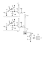
- FIG. 2 is a circuit diagram showing an example of the configuration of the light receiving unit 111 and the vertical analog addition circuit 112. As shown in FIG.
- the light receiving unit 111 is configured of a plurality of pixels arranged in a matrix, and FIG. 2 shows only the configuration of two pixels P (broken lines) of two rows of the same color in the light receiving unit 111.
- each pixel P is configured of a photodiode PD, a transfer transistor T1, a floating diffusion FD, a reset transistor T2, and an amplification transistor T3.
- the photodiode PD generates an electric charge in response to the received light.
- the charge generated in the photodiode PD is transferred to the floating diffusion FD by the transfer transistor T1 and accumulated.
- the reset and accumulation periods of the floating diffusion FD are set by the reset transistor T2, and a voltage based on the signal charge of the floating diffusion FD is amplified by the amplification transistor T3.
- the row selection switch T4 is turned on and off by a row selection signal, and outputs the signal current from the amplification transistor T3 to the CDS circuit 11a via the column line CA. All the row selection switches T4 in one column are connected to the common column line CA, and all the row selection switches T4 in the same row are simultaneously turned on to connect each column line CA from all the pixels P in the same row. A signal is supplied to each CDS circuit 11a via
- the row selection switch T4 is selectively turned on line by line by the vertical scanning circuit (not shown) when taking a still image.
- the row selection switch T4 of two rows of the same color for each line is turned on by the vertical scanning circuit when capturing a moving image.
- the pixel values of the pixels P of two rows of the same color are output via the column line CA at the time of moving image shooting.
- the CDS circuit 11a removes and outputs reset noise of pixel values of two rows of the same color.
- the output of the CDS circuit 11a is stored in the capacitor C1 via the transistor T5.
- a charge of the sum of pixel values of two pixels is accumulated in the capacitor C1.
- the accumulated charge of the capacitor C 1 is supplied to an analog-to-digital converter (ADC) 11 c via an amplifier 11 b to be converted into a digital signal and output to the controller 19.
- ADC analog-to-digital converter
- the addition pixel values of the pixels P of two rows of the same color are output from the ADC 11 c provided on each column line CA.
- the output of each ADC 11 c is sequentially output by a horizontal scanning circuit (not shown).
- the imaging unit 11 outputs only the added pixel value of the pixels P of the two rows of the same color at the time of moving image shooting, and can not output the pixel value of the single pixel P.
- the imaging unit 11 when the reading of the pixels P in two rows is completed by the horizontal scanning circuit at the time of moving image shooting, the pixels P in the next two rows are read. Note that each time the readout of the pixels P in two rows is completed, the pixels P in these rows are reset.
- the main body communication unit 12 is a communication interface for communicating with the interchangeable lens unit 20 mounted on the main body unit 10.
- the main body communication unit 12 also includes an electrical contact with the interchangeable lens unit 20.
- the clock unit 13 has a clocking function and a determination function of shooting date and time.
- the clock unit 13 outputs date / time data to the control unit 19 in order to add date / time data to the image data captured by the imaging unit 11.
- the operation input unit 14 has a power switch for switching the power state of the imaging apparatus 1 to the on state or the off state as a user interface for operation input, and a release switch for receiving an input of a still image release signal for giving a still image shooting instruction.
- a mode dial switch for switching various shooting modes set in the imaging device 1 an operation switch for switching various settings of the imaging device 1, a menu switch for causing the display unit 17 to display various settings of the imaging device 1, a recording medium 16
- a moving image switch for receiving an input of a moving image release signal for giving an instruction for moving image shooting.
- the release switch can be advanced and retracted by external pressure. When the release switch is pressed halfway, a 1st release signal for instructing a shooting preparation operation is input. On the other hand, when the release switch is full-pressed, a second release signal instructing still image shooting is input.
- the recording unit 15 is configured using a volatile memory and a non-volatile memory.
- the recording unit 15 temporarily records image data input from the imaging unit 11 via the control unit 19 and information being processed by the imaging device 1. Further, the recording unit 15 records various programs for operating the imaging device 1, an imaging program, various data used during execution of the program, and various parameters. Further, the recording unit 15 records a serial number for identifying the imaging device 1.
- the recording medium 16 is configured using a memory card or the like mounted from the outside of the imaging device 1.
- the recording medium 16 is detachably attached to the imaging device 1 via a memory I / F (not shown).
- a memory I / F (not shown).
- an image file for recording image data is written to the recording medium 16, or image file image data recorded on the recording medium 16 is read out.
- the image file is the image data generated by the imaging unit 11, and the electrical signals output from the replacement pixel to be replaced are different at the same time or different timings.
- the image data replaced by the electric signal of the imaging pixel and the position information on the position of the replaced pixel in the imaging unit 11 are recorded.
- the display unit 17 is configured using a display panel made of liquid crystal, organic EL (Electro Luminescence), or the like.
- the display unit 17 displays an image corresponding to the image data.
- a recview display in which the image data immediately after shooting is displayed for a predetermined time (for example, 3 seconds)
- a reproduction display in which the image data recorded in the recording medium 16 is reproduced
- the imaging unit 11 are continuous.
- a live view display that sequentially displays live view images corresponding to the image data to be generated in chronological order.
- the display unit 17 appropriately displays operation information of the imaging device 1 and information regarding imaging.
- the touch panel 18 is provided on the display screen of the display unit 17.
- the touch panel 18 detects a touch of an object from the outside, and outputs a position signal according to the detected touch position. Further, the touch panel 18 detects a position touched by the user based on the information displayed on the display unit 17, and accepts an input of an instruction signal instructing an operation to be performed by the imaging device 1 according to the detected contact position. It is also good.
- the touch panel 18 there are a resistive film method, a capacitance method, an optical method, and the like. In the first embodiment, any type of touch panel is applicable.
- the control unit 19 is configured using a CPU (Central Processing Unit) or the like.
- the control unit 19 transmits the control signal and various data to each unit constituting the imaging device 1 in accordance with an instruction signal input from the operation input unit 14 or the touch panel 18 to operate the imaging device 1. Control overall.
- the control unit 19 includes an AF signal calculation unit 191, an image processing unit 192, an image compression / decompression unit 193, an image file generation unit 194, and a recording control unit 195.
- the AF signal calculation unit 191 acquires an image signal of a pixel in a predetermined area from the image data input from the imaging unit 11, and generates an AF signal by the pupil division phase difference method based on the phase difference of the acquired image signal. Do.
- the AF signal calculation unit 191 outputs an AF signal to the interchangeable lens unit 20 via the main body communication unit 12. The details of the pupil division phase difference method by the AF signal calculation unit 191 will be described later.
- the image processing unit 192 generates processed image data obtained by performing various types of image processing including image quality correction processing on image data (RAW data) input from the imaging unit 11. Specifically, the image processing unit 192 performs at least gain processing for adjusting the brightness of the image, tone correction processing for correcting the tone, edge processing, smoothing processing, white balance processing, and color on the image data. Image processing including correction processing, noise reduction processing, ⁇ correction processing, and hue correction processing according to the shooting mode is performed to generate processed image data for display or recording.
- the image mode is a mode in which the image quality of an image to be developed is corrected according to a scene such as portrait shooting, landscape shooting, and night scene shooting.
- the image processing unit 192 functions as an image processing apparatus.
- the image compression / decompression unit 193 compresses the processed image data subjected to image processing by the image processing unit 192 according to a predetermined format, and outputs the compressed image data thus compressed to the recording medium 16.
- a predetermined format there are a JPEG (Joint Photographic Experts Group) system, a Motion JPEG system, an MP4 (H.264) system, and the like.
- the image compression / decompression unit 193 acquires image data (compressed image data) recorded in the recording medium 16, and decompresses (decompresses) the acquired image data and outputs the image data to the image file generation unit 194 or the recording unit 15. .
- the image file generation unit 194 receives positional information (addresses related to positions of image data before image quality correction (RAW data), processed image data and compressed image data, and replacement pixels in the imaging unit 11 and imaging pixels obtained by interpolating replacement pixels).
- An image file is generated in which information is recorded in association with range information indicating a range including each position, a shooting mode including the imaging device 1 and a shooting mode including the image processing parameter of the image processing unit 192.
- range information indicating a range including each position
- a shooting mode including the imaging device 1 and a shooting mode including the image processing parameter of the image processing unit 192.
- the recording control unit 195 causes the recording medium 16 to record the image file generated by the image file generation unit 194.
- the recording control unit 195 causes the image file generation unit 194 to generate an image file having contents according to an instruction signal input from the operation input unit 14 or the touch panel 18.
- the recording control unit 195 causes the image file generation unit 194 to generate an image file in which the RAW data and the photographing information are associated and recorded, and causes the recording medium 16 to record the image file.
- a communication unit or the like having a function may be further provided.
- the interchangeable lens unit 20 includes an optical system 21, a drive unit 22, a lens communication unit 23, an operation unit 24, a lens recording unit 25, and a lens control unit 26.
- the optical system 21 is configured using one or more lenses and a stop.
- the optical system 21 condenses light from a predetermined visual field area.
- the optical system 21 has an optical zoom function to change the angle of view and a focus function to change the focus.
- the drive unit 22 is configured using a DC motor or a stepping motor, and changes the focus position, the angle of view, and the like of the optical system 21 by moving the lens of the optical system 21 on the optical axis O1.
- the drive unit 22 also drives the stop of the optical system 21.
- the lens communication unit 23 is a communication interface for communicating with the main body communication unit 12 of the main body unit 10 when the interchangeable lens unit 20 is connected to the main body unit 10.
- the operation unit 24 is a ring provided around the lens barrel of the interchangeable lens unit 20, and instructs the input of an operation signal for starting the operation of the optical zoom in the optical system 21 or the adjustment of the focus position of the optical system 21. Accept an input of an instruction signal.
- the operation unit 24 may be a push switch or the like.
- the lens recording unit 25 is configured using a flash memory, and records a control program for determining the position and movement of the optical system 21, lens characteristics of the optical system 21, focal length, brightness number, and various parameters. .
- the lens control unit 26 is configured using a CPU or the like.
- the lens control unit 26 controls the operation of the interchangeable lens unit 20 according to an operation signal of the operation unit 24 or an instruction signal from the main unit 10. Specifically, the lens control unit 26 drives the drive unit 22 according to the operation signal of the operation unit 24 to focus the optical system 21, change the zoom, or change the aperture value.
- the lens control unit 26 transmits to the main body unit 10 focus position information of the interchangeable lens unit 20, focal length, and unique information for identifying the interchangeable lens unit 20. Send.
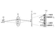
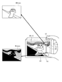
- FIG. 3 is a schematic view illustrating an outline of the pupil division phase difference method performed by the AF signal calculation unit 191. As shown in FIG. 3
- an optical image incident on the imaging device 1 from the subject Z1 via each optical path is imaged on the incident surface of the imaging element of the imaging unit 11 by the optical system 21.
- Two imaging units (for example, R imaging unit and L imaging unit) are configured as pixels for AF detection (hereinafter, referred to as AF pixels), and each light path is divided, for example, in the right direction and left direction in the exit pupil, and light from the left light (right light) from the right direction (left light) incident respectively to the R imaging unit 11 R and the L imaging unit 11 L.
- a part of the imaging unit 11 is enlarged and the R imaging unit 11 R and the L imaging unit 11 L are decentered with respect to the optical axis of the optical system 21 to make the right
- the light and the left light can be respectively incident on the R imaging unit 11 R and the L imaging unit 11 L.
- AF signal calculating unit 19 based on the phase difference between the R imaging unit 11 R, the image signal obtained by the L imaging unit 11 L L 1 and the image signals L 2, drive to drive the lens for focus adjustment
- AF signal calculating unit 191 based on the phase difference between the R imaging unit 11 R, the image signal obtained by the L imaging unit 11 L L 1 and the image signals L 2, drive to drive the lens for focus adjustment
- AF signal calculating unit 191 based on the phase difference between the R imaging unit 11 R, the image signal obtained by the L imaging unit 11 L L 1 and the image signals L 2
- the AF signal calculation unit 191 omits L pixels and uses only R pixels as AF pixels, and image signals obtained by a plurality of imaging pixels (hereinafter also referred to as N pixels) of by comparing the phase and the image signal obtained by the R imaging unit 11 R phase, it may generate a drive signal for focus adjustment.
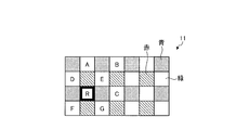
- FIG. 6 is a diagram for explaining a pixel array of the imaging unit 11.
- the dense hatching indicates a blue pixel on which the blue filter is disposed
- the rough hatching indicates a red pixel on which the red filter is disposed
- the solid pixel is a green pixel on which the green filter is disposed.
- a frame with a border indicates an AF pixel.
- Bayer arrangement is demonstrated to an example as a pixel arrangement, even if it is honeycomb arrangement, for example, it is applicable.
- the same arrangement is repeated in units of horizontal and vertical 2 ⁇ 2 pixels. That is, blue and red pixels are disposed diagonally in the 2 ⁇ 2 pixels, and green pixels are disposed in the remaining two diagonal pixels.
- the signs A to G are for specifying a pixel
- the pixel R is an R pixel for AF detection.
- a green filter for obtaining a green pixel is disposed.
- the imaging unit 11 uses the signal read from each pixel at the time of still image shooting as it is as each pixel value of the captured image and performs pixel interpolation after imaging.
- the imaging unit 11 adds one pixel value of four pixels of the same color to generate one pixel of the color. For example, the imaging unit 11 adds green pixels D to G to generate one green pixel, and adds pixels A, B, R, and C as pixels next to the generated pixels to generate the green pixel. The same is true for other colors.
- the pixel R is not an N pixel, image quality degradation occurs if one pixel is configured using the pixels A, B, R, and C as they are. Therefore, in the first embodiment, the imaging unit 11 generates image data (RAW data) by interpolating an AF pixel with another pixel.
- FIG. 7 is a diagram for explaining a pixel interpolation method performed by the imaging unit 11.
- FIG. 7 an example in which only an R pixel is used as an AF pixel will be described.
- the imaging unit 11 when performing imaging of a moving image, the imaging unit 11 generates an image signal from the light receiving unit 111 in order to quickly perform processing of generating one pixel by pixels of two columns of two rows of the same color. Is read out by adding two rows of pixels of the same color.
- the pixel values of the pixels A to G and R are represented by A to G and R, as shown in FIGS. 7A and 7B, the addition pixel values (D + F) and (E + G) are obtained for green pixels. ,..., (A + R), (B + C),.
- addition pixel values (D + E + F + G) are obtained by performing pixel addition of two columns of the same color on the addition pixel values read from the imaging unit 11. .., (A + B + R + C),.
- the pixel R is an R pixel that outputs a pixel value based on only light incident from the right direction of the exit pupil.
- one pixel is constituted by R imaging unit 11 R and the L imaging unit 11 L, if adding the pixel value of the pixel values of the R imaging unit 11 R and the L imaging unit 11 L, Also from such AF pixels, pixel values equivalent to N pixels can be obtained. That is, assuming that not only the R imaging unit 11 R but also the L imaging unit 11 L is provided at the position of the pixel R, the pixel value of the L imaging unit 11 L is estimated, and the pixel value of the pixel R is estimated. By adding the pixel values of the L imaging unit 11 L , it is possible to obtain a pixel value when N pixels are formed at the position of the pixel R.
- the imaging unit 11 performs the above-described addition readout for high-speed processing when capturing a moving image, and reads out pixel values of a single pixel from the light receiving unit 111 when capturing a moving image. Can not. Therefore, the imaging unit 11 can not directly read the pixel value of the pixel R, and can not directly obtain a pixel value twice as large as the pixel R as the value of N pixels at the position of the pixel R. For this reason, the position of the pixel R (see FIG. 6) is the central position surrounded by the pixels D to G, and the pixel value when N pixels are formed at this position is the added pixel value (D + E + F + G Estimated to be) / 4.
- the addition pixel value (D + E + F + G) / 8 is The pixel value of the L imaging unit 11 L at the position of the pixel R is set (FIG. 7C).
- the imaging unit 11 adds the pixel values (A + B + R + C ) in addition pixel value is a pixel value of the L image pickup unit 11 L (D + E + F + G) / 8 the value obtained by adding, pixel A, B, R, all C It is set as an addition pixel value at the time of comprising N pixels (Drawing 7 (d)).
- the imaging unit 11 needs to obtain a pixel value (pixel value of the R imaging unit) in the pixel R for AF processing at the time of moving image imaging.
- the image processing unit 192 outputs the added pixel value (A + R) from the imaging unit 11.
- the pixel value of the pixel R is estimated by subtracting the pixel value of the pixel A from the added pixel value (A + R).
- the pixel value of the pixel A is estimated to be the added pixel value (D + E + F + G) / 4.
- the imaging unit 11 obtains the pixel value of the pixel R by the addition pixel value (A + R) ⁇ the addition pixel value (D + E + F + G) / 4 (FIG. 7 (e)).
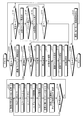
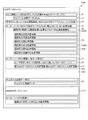
- FIG. 8 is a diagram showing an example of the configuration of an image file generated by the image file generation unit 194. As shown in FIG. 8
- An image file F100 shown in FIG. 8 is a file for recording RAW data in a format compliant with EXIF, and a header is provided similarly to EXIF, and various types of data are allocated by IFD (Image File Directory).
- the image file F100 information necessary for reproducing the main image data (main image data IFD0) and information at the time of shooting of the main image data (shooting information IFD1) are recorded in the field F1 at the beginning of the file.
- the RAW data DR is assigned to the main image data
- information at the time of shooting of the main image data is assigned information for specifying the imaging device 1 used at the time of shooting of RAW data, and information for shooting conditions.
- information corresponding to EXIF is assigned, and information such as aperture, focus distance, shutter speed, information such as image quality correction mode in image processing unit 192, image processing parameters, file name, user name, etc.
- Information defined in EXIF is assigned.
- thumbnail image data compressed by JPEG generated by the image compression / decompression unit 193 is allocated to the field F2, and information uniquely defined by the maker of the imaging device 1 (field) is allocated to the field F3.
- the Education and Manufacturing Note (IFD) is recorded. Since the first three fields F1 to F3 are created in the EXIF format, the image file F100 is formed so that the RAW data allocated to the main image data can be reproduced by various applications capable of processing the EXIF file. Ru.
- the image file F100 is assigned image processing information DS0A at the time of shooting of the main image data.
- the setting of the aperture of the imaging device 1 at the time of shooting of the RAW data DR for example, the setting of 0 EV, -1 EV, etc.
- the shutter speed, the shooting mode and the like are recorded.
- specific parameters obtained at the time of shooting are sequentially recorded.
- parameters necessary for image processing for reproducing the time of shooting are recorded as parameters, and then a reference parameter used when partially cutting out the RAW data DR (hereinafter, “cutout Various reference information is recorded.
- the aperture is recorded, for example, as 0 EV in the field F4 on the leading side, and a specific aperture value 5.6 or the like is recorded in the image processing information DS0A of the field F5 that follows.
- the image quality correction mode the auto white balance adjustment mode, the shooting mode for person shooting, etc. are recorded in the field F4 on the top side, and each color signal in this auto white balance adjustment mode is recorded in the image processing information DS0A of the field F5. And the parameters of color correction according to the shooting mode.
- various cutout reference information DS0B is set in the field F6.
- in-focus position information at the time of shooting detected from focus adjustment is recorded in the field F6.
- the in-focus position information at the time of shooting is position information of an area in focus in the image of the RAW data DR.
- the in-focus position information of the background detected in the focus search process at the time of shooting is recorded.
- Position information of the face detected at the time of shooting is recorded in the field F6.
- the control unit 19 detects an area where a face is photographed using a face template, and sets the area where the face is detected as the information of the face position.
- the imaging device 1 When the user has selected a shooting mode for shooting a person, the imaging device 1 performs focus adjustment to acquire the RAW data DR so that the area where the face is detected is in focus. In addition, when a face is not detected, that is recorded on the positional information on a face.
- the information on the backlight position is position information indicating a back light part in the imaging result, and the in-focus position in each part of the imaging result is detected at the time of the focus search.
- An area where it is determined that one object has been photographed, and an area where the in-focus position is closer to the front side and the luminance level is lower is detected, and position information of the detected area is set as information of the back light position.
- information on the saturation position is further recorded.
- the information on the saturation position is the position of the region where the luminance level is saturated by the dynamic range of the imaging device 1.
- the imaging device 1 changes the diaphragm at the time of photographing, determines the change in the luminance level of each part with respect to the change of the diaphragm, and detects a saturated region. Further, position information of the detected area is set as information of the saturation position. Further, in the image file F100, position information of the center of the optical axis at the time of shooting is recorded. Here, the position information at the center of the optical axis is set based on the information specifying the model of the lens provided in the lens. Note that, even if the backlight position information, the saturation position information, and the optical axis center position information can not detect the corresponding position information, the effect is recorded. Subsequently, various other parameters are sequentially assigned to the image file F100 to form shooting information DS0 at the time of shooting of the main image data.
- the shooting information DS1, DS2, ... of the editing process is the shooting information set in the editing process, corresponding to the image processing information DS0A for reproducing the shooting time assigned to the shooting information DS0 at the time of shooting It is set.
- history information is added to the shooting information such as the setting of the aperture, shutter speed, shooting mode, etc. assigned to the field F4 of the shooting information DS0 at the time of shooting, F7 is formed.
- the history information is information on the date and time when each piece of shooting information DS1, DS2,... Is set in the image file F100.
- specific image processing information corresponding to the imaging information assigned to the immediately preceding field F7 is recorded in the field F8.
- position information of AF pixels relating to the position of AF pixels in the light receiving unit 111 of the image pickup unit 11 and position information regarding image pickup pixels obtained by interpolating the AF pixels are recorded in the field F9.
- the image file F100 information necessary for reproducing the thumbnail image data DT is assigned following the area of the shooting information DS1, DS2,... Of this editing process, and the thumbnail image data DT is assigned to the subsequent field.
- RAW data DR which is main image data is allocated.
- the image file F100 is information corresponding to the cutout reference information (field F6) DS0B allocated to the photographing information DS0 at the time of photographing following the main image data, and the cutout reference information set at the time of the editing process is added It is made possible.
- the information to be added has the same field structure as the shooting information DS0 at the time of shooting, and history information is set in the same manner as the shooting information DS1 at the time of editing processing.
- the amount of data of the RAW data DR occupies about 95% of the total amount of data, but since this RAW data DR is allocated to the end of the file, the file head
- the thumbnail image data DT, the photographing information DS0, and the photographing information DS1 to DS2 of the editing process can be acquired by reproducing only about 5%.
- the image file generation unit 194 records the imaging result with the image file F100 according to the format illustrated in FIG. 8, RAW data DR output from the imaging unit 11 under the instruction of the recording control unit 195;
- the data of the image file F100 is generated by the photographing information DS and the thumbnail image data DT output from the recording control unit 195, the thumbnail image data DT by JPEG generated by the image compression / decompression unit 193, etc. and output to the recording medium 16 Do.
- FIG. 9 is a flowchart showing an outline of processing performed by the imaging device 1.
- the control unit 19 determines whether the imaging apparatus 1 is set to the imaging mode (step S101). When the control unit 19 determines that the imaging device 1 is set to the imaging mode (step S101: Yes), the imaging device 1 proceeds to step S102 described later. On the other hand, when the control unit 19 determines that the imaging device 1 is not set to the imaging mode (step S101: No), the imaging device 1 proceeds to step S122 described later.
- step S102 the control unit 19 causes the imaging unit 11 to perform imaging and causes the display unit 17 to display a live view image corresponding to the image data input from the imaging unit 11.
- the image processing unit 192 applies thinning processing to the image data from the imaging unit 11 according to the number of display pixels of the display unit 17, and then outputs the image data to the display unit 17.
- step S103 when an instruction signal instructing moving image shooting is input from the operation input unit 14 (step S103: Yes), the imaging device 1 reads out moving image pixel readout simultaneously read every two lines from the imaging unit 11 at the time of moving image shooting. A process is performed (step S104).
- FIG. 10 is a flowchart showing an outline of the moving image pixel readout process.
- the imaging unit 11 initializes variables L, M, and N for performing the calculation shown in FIG. 7 described above to 0 (step S201).
- the imaging unit 11 causes the vertical analog addition circuit 112 to add two pixels in two rows skipped in one row (step S202).
- the addition pixel values (D + F) of the green pixels D and F in FIG. 6 and the addition pixel values (E + G) of the pixels E and G are obtained.
- step S203 When two pixels in two rows are not two pixels including AF pixels (step S203: No), when the processing of all the columns of the light receiving unit 111 is not completed (step S206: No), the imaging unit 11 receives light The row of the unit 111 is changed (step S207), and the process returns to step S202. On the other hand, when the processing of all the lines of the light receiving unit 111 is completed (step S206: Yes), the imaging unit 11 proceeds to step S208.
- the imaging unit 11 adds four pixels skipped in one column by the horizontal digital addition circuit 113 (step S208). Thereby, for example, the addition pixel value (D + F) and the addition pixel value (E + G) are added.
- step S209 Yes
- the imaging unit 11 increments the variable M (step S210)
- the added pixel value S2 (M) (D + E + F + G) is stored in the AF memory 114.
- Temporary recording step S211.
- the addition pixel values of all four pixels surrounding the AF pixel are stored in the AF memory 114.
- step S209 If the four pixels added do not surround the AF pixel (step S209: No), the imaging unit 11 proceeds to step S212.
- step S212 when the added four pixels include an AF pixel (step S212: Yes), the imaging unit 11 increments the variable N (step S213), and the addition result (A + B + R + C) of four pixels is added to the added pixel value S3 (N ) (Step S214).
- the imaging unit 11 adds S2 (M) / 8 to S3 (N) (for example, obtains an added pixel value on the right side of FIG. 7 (see d (step S215).) After step S215, the imaging unit 11 proceeds to step S216.
- step S212 when the added four pixels do not include AF pixels (step S212: No), the imaging unit 11 proceeds to step S216.
- step S216: Yes when all the lines of the light receiving unit 111 are finished (step S216: Yes), the imaging device 1 returns to the main routine of FIG. On the other hand, when all the lines of the light receiving unit 111 are not finished (step S216: No), the imaging unit 11 changes the line of the light receiving unit 111 (step S217), and returns to step S202.
- step S105 the control unit 19 sets the addition pixel value S2 (J) of 4 pixels to 1 ⁇ 4 when the pixel surrounded by 4 pixels of the same color is an AF pixel, thereby setting the AF pixel to N pixels.
- the pixel value N (J) in the configured case is estimated.
- the AF signal calculation unit 191 subtracts the pixel value N (J) when the R pixel is formed of N pixels from the addition value S1 (J of two pixels including the R pixel (see FIG. e) Refer to step S106) and estimate the pixel value R (J) of the R pixel.
- the AF signal calculation unit 191 subtracts the pixel value R (J) when the AF pixel is configured by the R pixel from the pixel value N (J) when the AF pixel is configured by the N pixel, A pixel value L (J) is estimated when the AF pixel is formed of L pixels (step S107).
- the AF signal calculation unit 191 detects the correlation between the image signal obtained by the plurality of pixel values R (J) estimated and the image signal obtained by the plurality of pixel values L (J) estimated (step S108).
- the correlation between the image signal obtained by the plurality of estimated pixel values R (J) and the image signal obtained by the plurality of estimated pixel values N (J) is detected (step S109).
- the lens control unit 26 drives the drive unit 22 based on the AF signal input from the AF signal calculation unit 191 to perform focusing of the optical system 21 on the side of higher correlation (step S110).
- the AF signal calculation unit 191 adopts a combination that can obtain high correlation for phase difference detection for focusing. For example, when the correlation between the image signal obtained by the pixel value R (J) and the image signal obtained by the plurality of pixel values L (J) is higher, the AF signal calculation unit 191 sets the pixel value R (J Detects the phase difference between the image signal obtained by (a) and the image signal obtained by the plurality of pixel values L (J), and generates an AF signal for driving and controlling the interchangeable lens unit 20 based on the detected phase difference. Then, the data is output to the lens control unit 26. The AF signal is output to the lens control unit 26, and the lens control unit 26 drives the drive unit 22 to focus the optical system 21.
- the image processing unit 192 generates an image at the time of capturing a moving image by using the acquired 4-addition pixel value after focusing which is color data information for each acquired coordinate, performs predetermined image processing, and then performs processing.
- An image corresponding to the image data is displayed on the display unit 17 (step S111).
- the image compression / decompression unit 193 performs encoding processing on the processed image data generated by the image processing unit 192, and then causes the recording unit 15 to record the processed image data (step S111).
- step S112: Yes the imaging device 1 proceeds to step S117 described later.
- step S112: No the imaging device 1 returns to step S105 and continues moving image shooting.
- step S103 when there is no instruction signal instructing moving image shooting from operation input unit 14 (step S103: No), when an instruction signal instructing still image shooting is input (step S113: Yes), imaging device 1 Executes AF processing for automatically adjusting the focus (step S114), and executes still image shooting (step S115).
- the control unit 19 records the image data (RAW data DR) input from the imaging unit 11 in the recording unit 15.
- the image processing unit 192 acquires image data from the recording unit 15, and performs image processing including interpolation of AF pixels on the acquired image data to generate processed image data (step S116).
- the image file generation unit 194 performs position information of AF pixels regarding the position of AF pixels in the imaging unit 11 in which the image processing unit 192 performs interpolation processing on the RAW data DR and the processed image data recorded in the recording unit 15; And an image file in which positional information of replacement pixels relating to the position of the imaging pixel for interpolating the AF pixel is associated and generated (step S117), and the generated image file is recorded on the recording medium 16 (step S118) .
- the imaging device 1 generates high-speed image data in order to correspond to the live view image, but by recording as RAW data DR, another image processing device, for example, When developing the RAW data DR by the computer, using the position information of the AF pixel and the position information of the image pickup pixel substituted for the AF pixel, a more natural and accurate interpolation or replacement or composition image is generated be able to.
- the image file generation unit 194 generates an image file by associating the moving image data recorded in the recording unit 15 with the positional information on AF pixels and the information on interpolation pixels, as in the case of still image shooting.
- control unit 19 causes the display unit 17 to display an image corresponding to the recorded processed image data on the recording unit 17 (step S119).
- step S120: Yes the imaging apparatus 1 ends the present process.
- step S120: No the imaging device 1 proceeds to step S121.
- control unit 19 receives an operation to change the mode of the imaging device 1 to the imaging mode or the reproduction mode (step S121). After step S121, the imaging device 1 returns to step S101.
- step S113 when the instruction signal for instructing still image shooting is not input via the operation input unit 14 (step S113: No), the imaging device 1 proceeds to step S120.
- step S101: No the case where the imaging apparatus 1 is not set to the imaging mode (step S101: No) will be described.
- the control unit 19 causes the display unit 17 to display a list of image files recorded in the recording medium 16 (step S123). .
- the control unit 19 causes the display unit 17 to display a list of thumbnail images corresponding to the image data included in the image file.
- step S124 When an image file is selected (step S124: Yes), the control unit 19 causes the display unit 17 to reproduce an image corresponding to the image data of the selected image file (step S125). At this time, the image processing unit 192 develops the image data by performing image processing using the RAW data DR recorded in the image file and the position information of the interpolation pixel. Thus, in the first embodiment, the image processing unit 192 functions as an image processing apparatus. Thereafter, the imaging device 1 returns to step S122.
- step S124 when the image file is not selected within a predetermined time (for example, 3 seconds) (step S124: No), the imaging device 1 proceeds to step S126.
- a predetermined time for example, 3 seconds
- step S126: Yes when an instruction signal for ending the reproduction mode is input from the operation input unit 14 (step S126: Yes), the imaging device 1 proceeds to step S120. On the other hand, when the instruction signal for ending the reproduction mode is not input through the operation input unit 14 (step S126: No), the imaging device 1 returns to step S123.
- step S122 when the imaging device 1 is not set to the reproduction mode (step S122: No), the imaging device 1 returns to step S101.
- the image file before the image quality correction generated by the image pickup unit 11 by the image file generation unit 194 and the image pickup pixels obtained by interpolating the AF pixels and the interpolation pixels in the image pickup unit 11 (N Since the image file F100 is generated in which the positional information on each position is associated with each other and recorded, the image can be developed with high image quality in the post-processing for performing the image quality correction processing for display on the RAW data DR. .
- the first embodiment even if pixel values of a plurality of pixels are added after being output from the imaging unit 11 having AF pixels for high-speed processing at the time of moving images, simple arithmetic processing Thus, it is possible to estimate the addition pixel value when the AF pixel is a normal pixel, and to obtain a high quality moving image. Also in this case, the pixel value of the AF pixel can be acquired by a simple calculation process, and focusing can be performed with high accuracy.
- simple arithmetic processing is simple arithmetic operation on the stored addition result, each storing the addition result depending on whether the plurality of pixels to be added are pixels including AF pixels or pixels surrounding AF pixels. To perform high-speed processing.
- the image processing unit 192 performs image quality correction processing of the RAW data DR based on the position information of the AF pixel and the position information of the imaging pixel obtained by interpolating the AF pixel. Although it has been generated, for example, even an extracted pixel extracted in edge extraction can be applied. In this case, the image processing unit 192 can develop an image with higher image quality by reducing the weight of the interpolation pixel based on the position information of the extraction pixel and gazing at the pixels around it. Furthermore, in the general noise reduction processing, the flat portion and the edge portion are determined, but the determination standard at that time can also be changed according to the position information of the extracted pixel. As a result, unnecessary image quality deterioration due to noise reduction processing by the image processing unit 192 can be prevented.
- pixels having L imaging units 11 L and R imaging units 11 R that receive light from horizontal and horizontal directions are used as AF pixels. It is apparent that the same can be applied to an example using a pixel having two imaging units that receive light of.
- image data before image quality correction is recorded as RAW data
- image data obtained by interpolating replacement pixels may be recorded as RAW data, or may be recorded before image quality correction (before image quality correction).
- the data of replacement pixels may be separately recorded in an image file.
- any one can be selected whether or not the image quality correction process for display is performed on the RAW data DR. If image quality equivalent to that of an imaging device can be realized by performing correction, substitution, or replacement by various methods, and if there is a post-processing that separately performs image quality correction processing for display, higher quality can be obtained by using these information. It can be developed with image quality.
- only the pixel data has been described for replacement, but it is possible not only to replace with other pixels, but also to correct by analogy from the pattern of the image. ing.
- the focus pixel (AF pixel) is corrected, an example of embedding the exposure adjustment pixel in the image pickup device, a pixel for controlling the light amount of a strobe, and a pixel for correcting the exposure as described later
- the pixel is embedded in the same way as the present embodiment, and the pixel is not the pixel or the pixel data for the image for photographing or reproduction display, and this is not used as it is. It becomes. Therefore, it is important to provide the file with information indicating the location of the pixel in the later steps when handling this. Not only that, but information on what kind of replacement and correction should be made may be included in the file. For example, replacement rules as shown in FIG.
- the imaging apparatus according to the second embodiment is different in configuration from the imaging apparatus according to the above-described first embodiment. Therefore, in the second embodiment, after the configuration of the imaging apparatus is described, processing performed by the imaging apparatus according to the second embodiment will be described. In the following, the same components as those of the first embodiment described above will be described with the same reference numerals.
- FIG. 12 is a block diagram showing a functional configuration of the imaging device according to the second embodiment of the present invention.
- An imaging device 200 illustrated in FIG. 12 includes a main body unit 210 and an interchangeable lens unit 20.
- the main body unit 210 includes an imaging unit 11, a main body communication unit 12, a clock unit 13, an operation input unit 14, a recording unit 15, a recording medium 16, a display unit 17, a touch panel 18, and a subject analysis unit 211. , And a control unit 212.
- the subject analysis unit 211 analyzes the pixel area of the imaging unit 11 to be interpolated based on the image data generated by the imaging unit 11 via the control unit 212. Specifically, the subject analysis unit 211 determines the brightness and the exposure state of the subject based on the luminance information included in the image data, for example, the exposure value limit state (overexposure), the underexposure state (underexposure) or the appropriate exposure state Are analyzed, and the analysis result is output to the control unit 212.
- the control unit 212 is configured using a CPU or the like.
- the control unit 212 transfers the control signal and various data to each unit constituting the imaging device 200 in accordance with an instruction signal input from the operation input unit 14 or the touch panel 18 to operate the imaging device 200. Control overall.
- the control unit 212 includes an AF signal calculation unit 191, an image processing unit 192, an image compression / decompression unit 193, an image file generation unit 194, a recording control unit 195, and an image combining unit 213.
- the image combining unit 213 expands the dynamic range based on the analysis result of the subject analysis unit 211 and the image data input from the imaging unit 11 when the imaging device 200 performs imaging in the HDR (High Dynamic Range) imaging mode.
- image data Specifically, in the image combining unit 213, two image data input from the imaging unit 11, for example, image data in which the dynamic lens is saturated in some pixels (exposure over image) and noise in some pixels Image data adjusted with a dynamic lens is generated by replacing a pixel in which noise is occurring or a saturated pixel with another pixel using the generated image data (under-exposure image).
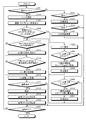
- FIG. 13 is a flowchart showing an outline of processing performed by the imaging device 200.
- step S301 when the imaging device 200 is set to the imaging mode (step S301: Yes), the control unit 212 communicates with the interchangeable lens unit 20 via the main unit communication unit 12 and the lens communication unit 23. (Step S302).
- control unit 212 causes the imaging unit 11 to perform imaging and causes the display unit 17 to display a live view image corresponding to the image data input from the imaging unit 11 (step S303).
- image processing unit 192 applies thinning processing to the image data from the imaging unit 11 according to the number of display pixels of the display unit 17, and then outputs the image data to the display unit 17.
- the control unit 212 determines whether the slide touch or the release switch of the operation input unit 14 has been half-pressed from the outside of the screen of the display unit 17 (step S304). Specifically, the control unit 212 detects a touch position from the outside of the screen of the display unit 17 from the touch panel 18, and determines whether the touch position changes with time, thereby performing slide touch. Decide whether or not.
- the imaging device 200 proceeds to step S305 described later.
- step S304 determines that the slide touch or the release switch of the operation input unit 14 is not half-pressed from the outside of the screen of the display unit 17 (step S304: No).
- the imaging device 200 will be described later. It transfers to step S312.
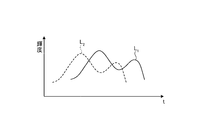
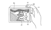
- the HDR bar M1 displays, for example, a bar position upper end icon Y1 for receiving an input of an instruction signal for instructing image data on the overexposure side, and a bar position lower end icon Y2 for receiving input of an instruction signal for instructing image data on the underexposure side. Be done.
- Step S306 when the bar position upper end icon Y1 is slide-operated via the touch panel 18 (step S306: Yes), the image data on the + side is used as a reference of the composite image, and the exposure amount is increased or decreased according to the slide movement distance.
- Step S307 The composite image of HDR is displayed on the display unit 17 (step S308).
- the image combining unit 213 sets the exposure amount of the image W h1 and the image W u1 to be combined with each other according to the movement distance of the slide, using the image W h1 on the + side as the reference of the combined image.
- the composite image W n + 1 is generated by increasing or decreasing as appropriate.
- the imaging device 200 proceeds to step S312 described later.
- step S306 When the bar position upper end icon Y1 is not slide operated through the touch panel 18 (step S306: No), when the bar position lower end icon Y2 is slide operated through the touch panel 18 (step S309: Yes), the-side The exposure amount is increased or decreased according to the movement distance of the slide by using the image data of B as the reference of the combined image (step S310), and the combined image of HDR is displayed on the display unit 17 (step S311).
- the image combining unit 213 sets the exposure amounts of the image W hmax and the image W umax to be combined with each other according to the movement distance of the slide, using the image W umax on the ⁇ side as the reference of the combined image.
- the composite image W n + 2 is generated by increasing or decreasing the ratio as appropriate.
- step S311 the imaging device 200 proceeds to step S312 described later.
- step S309 when the bar position lower end icon Y2 is not slide-operated via the touch panel 18 (step S309: No), the imaging device 200 proceeds to step S312.
- step S312 determines whether there is no touch operation.
- step S312 determines whether there is no touch operation after the display unit 17 displays the live view image.
- step S312 determines that there is no touch operation after the display unit 17 displays the live view image.
- step S313 the image combining unit 213 combines two pieces of image data adjusted in ⁇ 2 steps from the image data of the proper exposure to generate a combined image.
- the image combining unit 213 may combine three pieces of the image data of the proper exposure, the image data of the -2 step exposure, and the image data of the +2 step exposure to generate a combined image.
- step S314: Yes The unit 212 deletes the HDR bar M1 from the live view image of the display unit 17 (step S315). After step S315, the imaging device 200 proceeds to step S316.
- the imaging apparatus 200 executes AE ⁇ AF processing (step S316).
- step S317 Yes
- the imaging device 200 executes still image shooting (step S318).
- the control unit 212 records the two image data (RAW data DR) input from the imaging unit 11 in the recording unit 15.
- the image file generation unit 194 generates HDR image RAW data of the two pre-correction image data (RAW data DR) recorded in the recording unit 15 and the HDR image generated by the image synthesis unit 213 as the RAW data DR.
- RAW data pixels are added to each other to generate an image file in which position information of interpolated pixels is associated and recorded (step S319).
- the image file generation unit 194 generates an image file.
- the image file F200 two RAW data (first RAW data, second RAW data) before correction and HDR image data are stored in the field F9. Further, in the field F9, position information regarding the position of a pixel obtained by adding and replacing pixels in the HDR image RAW data is recorded.
- the image file generation unit 194 records the generated image file on the recording medium 16 (step S320).
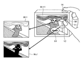
- the imaging device 200 generates high-speed image data in order to correspond to the live view image, but by recording as RAW data DR, another image processing device, for example,
- RAW data DR another image processing device
- more natural and accurate replacement, composition, and correction can be performed by using the position information of replacement pixels ((FIG. 18A to FIG. 18C)) And so on to generate an HDR image (Fig. 18 (d)).
- step S321: Yes the imaging device 200 ends the present process.
- step S321: No the imaging device 1 returns to step S301.
- step S301 when the imaging device 200 is not set to the photographing mode (step S301: No), when the imaging device 200 is set to the reproduction mode (step S322: Yes), the control unit 212 records the recording medium
- the display unit 17 reproduces the image data of the image file recorded in 16 (step S323).
- the image processing unit 192 may generate an HDR image based on the two RAW data stored in the image file and the position information of the replacement pixel.
- the HDR image taken can be generated (see, for example, FIG. 18).
- step S324: Yes when the image is changed via the operation input unit 14 (step S324: Yes), the control unit 212 changes the image file to the next image file to be recorded by the recording medium 16 (step S325). , And move on to step S321.
- step S324: No when the image is not changed via the operation input unit 14 (step S324: No), the imaging device 1 proceeds to step S321.
- step S322 when the imaging device 200 is not set to the reproduction mode (step S322: No), the imaging device 200 proceeds to step S321.
- the image file before the image quality correction generated by the image pickup unit 11 by the image file generation unit 194 and the other pixels in which the correction pixel and the correction pixel by image processing in the image pickup unit 11 are replaced Since the image file F 200 is generated in which positional information on the positions of the imaging pixels is associated with each other, development can be performed with high image quality when image quality correction processing for display is performed on the RAW data DR.
- the first RAW data and the second RAW data are recorded in one image file, but as shown in FIG. 19, for example, the images of the first RAW data and the second RAW data in the recording medium 16
- the specification information of the file may be recorded in association with the image file F 300 in which the RAW data DR of HDR is recorded. Thereby, the capacity of one image file can be reduced.
- the image file F200 is generated in which the correction pixel by the image processing in the image pickup unit 11 is associated with the position information related to the position of each of the other imaging pixels replacing the correction pixel.
- Data indicating the previous necessary image portion may be recorded as RAW data, or data indicating an image portion corrected after image quality correction (data representing a pixel) may be recorded as RAW data .
- data indicating an area may be separately recorded in an image file. In this way, if only the corrected part and the part requiring correction are recorded, correction of the image quality of that part, substitution of the image, and data replacement can be performed by various methods, and image quality different from that of the imaging device can be realized. Become.
- the second embodiment has been described by replacing pixel data, it is possible not only to replace by other pixels, but also to correct by analogy from the pattern of the image, and to include such cases as well.
- the image portion for HDR is corrected here, other image portions that need to be replaced may be recorded so as to be correctable.
- the pixel is not pixel data that can be used as it is for photographing and reproduction images, and the above-described correction, substitution, and replacement processing are required. Therefore, it is important to provide the file with information indicating the location of the pixel in the later steps when handling this. Not only that, but information on what kind of replacement and correction should be made may be included in the file. Information on replacement rules or replacement pixels may be provided.
- the present invention can be carried out even with an image reproduction device that performs image reproduction of an image file for recording image data.
- the image generation device is an acquisition step of acquiring replacement target pixel information regarding a position of a replacement pixel which is a pixel constituting an image corresponding to image data and has been replaced by another pixel;
- the identification step of identifying a replacement pixel from a plurality of electrical signals respectively output from a plurality of pixels constituting an image corresponding to the image data based on the acquired replacement target pixel information, and the replacement pixel identified in the identification step
- a generation step of generating interpolation image data by interpolating with a plurality of electric signals respectively output from a plurality of images, and a reproduction step of reproducing the interpolation image data generated in the generation step are executed.
- the image generation device is an information processing device including an imaging device, a portable device including a smartphone, an electronic device such as a tablet type portable device, a head mounted display, and a display monitor such as a PC.
- the image processing unit is incorporated in the control unit, but an image processing unit may be separately provided, for example. Furthermore, a plurality of image processing units (image engines) may be provided.
- the image processing unit is incorporated in the imaging device as an image processing apparatus, but an image processing unit may be separately provided.
- the image file is recorded in the recording medium, but it may be output to another image processing apparatus, for example, an electronic apparatus such as a mobile phone or an image processing apparatus equipped with an image processing unit via the Internet. You may
- the image pickup apparatus is also applicable to electronic devices such as a digital video camera to which an accessory etc. can be attached and a portable telephone or tablet type portable device having a photographing function. It can apply.
- the program to be executed by the imaging device and the image processing device according to the present invention is file data of an installable format or an executable format, and is a CD-ROM, a flexible disk (FD), a CD-R, a DVD (Digital Versatile Disk). ), A USB medium, a flash memory, etc., and provided by being recorded on a computer readable recording medium.
- the program to be executed by the imaging device and the image processing device according to the present invention may be stored on a computer connected to a network such as the Internet and provided by being downloaded via the network. Furthermore, the program to be executed by the imaging device and the image processing device according to the present invention may be provided or distributed via a network such as the Internet.
- Imaging apparatus 10 210 main body 11 imaging section 12 main body communication section 13 clock section 14 operation input section 15 recording section 16 recording medium 17 display section 18 touch panel 19, 212 control section 20 interchangeable lens section 21 optical system 22 drive section Reference Signs List 23 lens communication unit 24 operation unit 25 lens recording unit 26 lens control unit 111 light receiving unit 112 vertical analog addition circuit 113 horizontal digital addition circuit 114 memory for AF 191 AF signal calculation unit 192 image processing unit 193 image compression / decompression unit 194 image file generation Part 195 Recording control part 211 Subject analysis part 213 Image composition part
Abstract
Provided are an imaging device capable of developing RAW data at a higher image quality, an image processing device, a recording medium that records image files, a recording method, an image playback method, and a program. The imaging device comprises: an imaging unit (11) that generates image data having electric signals, that are output from replacement pixels which are to be replaced and are among a plurality of electric signals output from each of a plurality of pixels, replaced by electric signals for different imaging pixels obtained at the same or a different timing; and an image file generation unit (194) that generates image files that associate and record image data generated by the imaging unit (11) and position information relating to the position of the replacement pixels in the imaging unit (11).
Description
本発明は、被写体を撮像して光電変換を行うことによって電子的な画像データを生成する撮像装置、画像データに画像処理を施す画像処理装置、画像ファイルを記録した記録媒体、画像データの記録方法、画像データを記録する画像ファイルの画像再生方法およびプログラムに関する。
The present invention relates to an imaging device for generating electronic image data by imaging a subject and performing photoelectric conversion, an image processing device for performing image processing on image data, a recording medium recording an image file, and a recording method for image data The present invention relates to an image reproduction method and program of an image file for recording image data.
近年、デジタルカメラやデジタルビデオカメラ等の撮像装置では、RAWデータの形式で撮像結果をメモリカード等の記録媒体に記録するものが知られている。ここで、RAWデータとは、撮像素子から得られる撮像結果の画像データであって、γ補正処理、ホワイトバランス調整処理および周波数特性の補正処理等の撮像結果を表示するための一連の画質補正処理を実行していない画質補正前の画像データである。このようなRAWデータを記録する撮像装置として、画質補正前のRAWデータと、撮影時の画質補正処理を特定する画質特定情報とを対応付けて記録するものが知られている(特許文献1参照)。
BACKGROUND In recent years, in imaging devices such as digital cameras and digital video cameras, those that record imaging results in a recording medium such as a memory card in the form of RAW data are known. Here, RAW data is image data of an imaging result obtained from an imaging element, and is a series of image quality correction processing for displaying an imaging result such as γ correction processing, white balance adjustment processing, and correction processing of frequency characteristics. Image data before image quality correction. As an imaging apparatus for recording such RAW data, one is known that records RAW data before image quality correction in association with image quality specifying information for specifying image quality correction processing at the time of shooting (see Patent Document 1). ).
しかしながら、上述した特許文献1で記録するRAWデータは、たとえば撮像素子の画素欠陥を周辺の他の画素の画像データで補間した後のデータである。このため、パーソナルコンピュータ等の他の画像処理装置で記録媒体に記録されたRAWデータに対して表示用の画質補正処理を行って現像すると、その制約が画質に影響した。
However, the RAW data to be recorded in Patent Document 1 described above is, for example, data obtained by interpolating a pixel defect of the imaging device with image data of another pixel in the vicinity. For this reason, when image quality correction processing for display is performed on the RAW data recorded on the recording medium by another image processing apparatus such as a personal computer and developed, the restriction affects the image quality.
本発明は、上記に鑑みてなされたものであって、RAWデータに対してさらに高画質で現像することができる撮像装置、画像処理装置、画像ファイル、記録方法およびプログラムを提供することを目的とする。
The present invention has been made in view of the above, and it is an object of the present invention to provide an imaging device, an image processing device, an image file, a recording method, and a program capable of developing RAW data with higher image quality. Do.
上述した課題を解決し、目的を達成するために、本発明にかかる撮像装置は、複数の画素からそれぞれ出力される複数の電気信号のうち、置き換え対象となる置き換え画素から出力される電気信号を、同時、または異なるタイミングで得られた異なる撮像用画素の電気信号によって置き換えた画像データを生成する撮像部と、前記撮像部が生成した前記画像データと、前記撮像部における前記置き換え画素の位置に関する位置情報とを対応付けて記録する画像ファイルを生成する画像ファイル生成部と、を備えたことを特徴とする。
In order to solve the problems described above and to achieve the object, an imaging device according to the present invention comprises an electrical signal output from a replacement pixel to be replaced among a plurality of electrical signals respectively output from a plurality of pixels An imaging unit that generates image data replaced with electric signals of different imaging pixels obtained at the same time or different timing, the image data generated by the imaging unit, and the position of the replacement pixel in the imaging unit And an image file generation unit configured to generate an image file to be recorded in association with position information.
また、本発明にかかる撮像装置は、上記発明において、前記置き換え画素は、画素が欠陥した欠陥画素、当該撮像装置のピントを検出する際の検出用画素、画像を構成する画素とは異なるカラーフィルター(特定の波長を検出するためのBPF(Band Pass Filter)など)を有する画素、エッジ抽出において抽出した抽出画素および他の画像データを用いて画素信号を補って補正する補正対象の補正画素のいずれか一つ以上であることを特徴とする。近年、撮像素子には、様々な機能を有するものがあり、画素の全てが撮像用に使えるわけではないので、画像形成に使用しない画素データ、使用に不向きな画素データ、画像用以外の画素データは、画像化時に把握しておく必要がある。これが分かると、補正したり代用したり、置き換えたりして良好な画像が再生できる。
Further, in the imaging device according to the present invention, in the above-mentioned invention, the replacement pixel is a defective pixel in which the pixel is defective, a detection pixel when detecting the focus of the imaging device, and a color filter different from pixels constituting an image. Any of pixels having a BPF (Band Pass Filter) for detecting a specific wavelength, an extraction pixel extracted in edge extraction, and a correction pixel to be corrected for correcting a pixel signal by using other image data It is characterized by one or more. In recent years, some imaging devices have various functions, and not all pixels can be used for imaging, so pixel data not used for image formation, pixel data unsuitable for use, and pixel data other than for images Needs to be grasped at the time of imaging. Once this is known, a good image can be reproduced by correcting, substituting, or replacing.
また、本発明にかかる撮像装置は、上記発明において、撮影パラメータを調整するための専用機能画素、または撮影条件で決まる画像領域に相当する画素であることを特徴とする。
In the imaging device according to the present invention, in the above-described invention, the imaging device is a dedicated function pixel for adjusting a shooting parameter, or a pixel corresponding to an image area determined by a shooting condition.
また、本発明にかかる画像処理装置は、複数の画素を有する撮像部を備えた撮像装置が生成した画像ファイルに対して画像処理を施す画像処理装置において、前記撮像部によって生成された画像データであって、置き換え対象となる置き換え画素から出力される電気信号を、同時、または異なるタイミングで得られた異なる撮像用画素の電気信号によって置き換えた画像データと、前記撮像部における前記置き換え画素の位置に関する位置情報とを対応付けて記録した画像ファイルを取得して、取得した前記画像ファイルが記録する前記位置情報に基づいて、前記画像データに画質補正処理を行って処理画像データを生成する画像処理部と、を備えたことを特徴とする。
An image processing apparatus according to the present invention is an image processing apparatus for performing image processing on an image file generated by an imaging apparatus including an imaging unit having a plurality of pixels, wherein the image data is generated by the imaging unit. Image data in which electrical signals output from replacement pixels to be replaced are replaced with electrical signals of different imaging pixels obtained at the same time or different timing, and the position of the replacement pixels in the imaging unit An image processing unit that acquires an image file recorded in association with positional information, and performs image quality correction processing on the image data based on the positional information recorded by the acquired image file to generate processed image data And.
また、本発明にかかる画像処理装置は、上記発明において、前記処理画像データに対応する処理画像を再生表示する表示部と、をさらに備えたことを特徴とする。
Further, the image processing apparatus according to the present invention is characterized in that, in the above-mentioned invention, a display section for reproducing and displaying a processed image corresponding to the processed image data.
また、本発明にかかる記録媒体は、複数の画素を有する撮像部を備えた撮像装置が生成する画像ファイルを記録した記録媒体であって、前記画像ファイルは、前記撮像部によって生成された画像データであって、置き換え対象となる置き換え画素から出力される電気信号を、同時、または異なるタイミングで得られた異なる撮像用画素の電気信号によって置き換えた画像データと、前記撮像部における前記置き換え画素の位置に関する位置情報と、を記録することを特徴とする。
A recording medium according to the present invention is a recording medium recording an image file generated by an imaging device including an imaging unit having a plurality of pixels, wherein the image file is image data generated by the imaging unit. Image data in which electrical signals output from replacement pixels to be replaced are replaced with electrical signals of different imaging pixels obtained at the same time or at different timings, and positions of the replacement pixels in the imaging unit And position information on the
また、本発明にかかる記録方法は、複数の画素を有する撮像部を備えた撮像装置が実行する記録方法であって、複数の画素からそれぞれ出力される複数の電気信号のうち、置き換え対象となる置き換え画素から出力される電気信号を、同時、または異なるタイミングで得られた異なる撮像用画素の電気信号によって置き換えた画像データを生成する撮像ステップと、前記撮像ステップで生成した前記画像データと、前記撮像ステップにおける前記置き換え画素の位置に関する位置情報とを対応付けて記録する画像ファイルを生成する画像ファイル生成ステップと、を実行することを特徴とする。
Further, a recording method according to the present invention is a recording method performed by an imaging apparatus including an imaging unit having a plurality of pixels, which is to be replaced among a plurality of electric signals output from the plurality of pixels. An imaging step of generating image data in which electrical signals output from the replacement pixels are replaced by electrical signals of different imaging pixels obtained at the same time or different timings; the image data generated in the imaging step; An image file generation step of generating an image file in which the position information related to the position of the replacement pixel in the imaging step is associated and recorded.
また、本発明にかかる画像再生方法は、画像データを記録する画像ファイルの画像再生を行う画像再生機器が実行する画像再生方法であって、前記画像データに対応する画像を構成する画素であって、他の画素に置き換えられた置き換え画素の位置に関する置き換え対象画素情報を取得する取得ステップと、前記取得ステップで取得した前記置き換え対象画素情報に基づいて、前記画像データに対応する画像を構成する複数の画素からそれぞれ出力される複数の電気信号から前記置き換え画素を特定する特定ステップと、前記特定ステップで特定した前記置き換え画素を、前記複数の画像からそれぞれ出力される複数の電気信号で補間して補間画像データを生成する生成ステップと、前記生成ステップで生成した前記補間画像データを再生する再生ステップと、を実行することを特徴とする。
Further, an image reproducing method according to the present invention is an image reproducing method executed by an image reproducing apparatus for reproducing an image of an image file for recording image data, which is a pixel constituting an image corresponding to the image data. A plurality of images forming an image corresponding to the image data based on an acquisition step of acquiring replacement target pixel information regarding a position of a replacement pixel replaced by another pixel, and the replacement target pixel information acquired in the acquisition step Specific step of specifying the replacement pixel from a plurality of electric signals output from each of the pixels and interpolation of the replacement pixel specified in the specifying step with a plurality of electric signals respectively output from the plurality of images Generating the interpolated image data; and reproducing the interpolated image data generated in the generating step And executes the regeneration step that, a.
また、本発明にかかるプログラムは、複数の画素を有する撮像部を備えた撮像装置に、複数の画素からそれぞれ出力される複数の電気信号のうち、置き換え対象となる置き換え画素から出力される電気信号を、同時、または異なるタイミングで得られた異なる撮像用画素の電気信号によって置き換えた画像データを生成する撮像ステップと、前記撮像ステップで生成した前記画像データと、前記撮像ステップにおける前記置き換え画素の位置に関する位置情報とを対応付けて記録する画像ファイルを生成する画像ファイル生成ステップと、を実行させることを特徴とする。
Further, a program according to the present invention is an electric signal output from a replacement pixel to be replaced among a plurality of electric signals output from a plurality of pixels to an imaging device including an imaging unit having a plurality of pixels. An imaging step of generating image data in which electric signals of different imaging pixels obtained at the same time or different timings are generated, the image data generated in the imaging step, and a position of the replacement pixel in the imaging step And an image file generating step of generating an image file in which the position information related to the position information is associated and recorded.
本発明によれば、画像ファイル生成部がRWAデータと補間画素や置き換え画素の位置に関する位置情報とを対応付けて記録した画像ファイルを生成するので、RAWデータに対して表示用の画質補正処理を行う際に、再生時の自由度を増して高画質で現像することができるという効果を奏する。
According to the present invention, since the image file generation unit generates the image file in which the RWA data and the positional information on the positions of the interpolation pixel and the replacement pixel are associated with each other, the image quality correction process for displaying the RAW data is performed. When being performed, it is possible to increase the degree of freedom during reproduction and to develop with high image quality.
以下に、図面を参照して、本発明を実施するための形態(以下、「実施の形態」という)について説明する。また、この実施の形態により、この発明が限定されるものではない。さらに、図面の記載において、同一の部分には同一の符号を付している。
Hereinafter, modes for carrying out the present invention (hereinafter referred to as “embodiments”) will be described with reference to the drawings. Further, the present invention is not limited by the embodiment. Furthermore, in the description of the drawings, the same parts are given the same reference numerals.
(実施の形態1)
図1は、本発明の実施の形態1にかかる撮像装置の機能構成を示すブロック図である。図1に示す撮像装置1は、本体部10と、本体部10に着脱自在であり、所定の視野領域から光を集光する交換レンズ部20と、を備える。Embodiment 1
FIG. 1 is a block diagram showing a functional configuration of the imaging device according to the first embodiment of the present invention. Theimaging device 1 illustrated in FIG. 1 includes a main body unit 10, and an interchangeable lens unit 20 that is detachable from the main body unit 10 and that condenses light from a predetermined visual field area.
図1は、本発明の実施の形態1にかかる撮像装置の機能構成を示すブロック図である。図1に示す撮像装置1は、本体部10と、本体部10に着脱自在であり、所定の視野領域から光を集光する交換レンズ部20と、を備える。
FIG. 1 is a block diagram showing a functional configuration of the imaging device according to the first embodiment of the present invention. The
本体部10は、撮像部11と、本体通信部12と、時計部13と、操作入力部14と、記録部15と、記録媒体16と、表示部17と、タッチパネル18と、制御部19と、を備える。
The main body unit 10 includes an imaging unit 11, a main body communication unit 12, a clock unit 13, an operation input unit 14, a recording unit 15, a recording medium 16, a display unit 17, a touch panel 18, and a control unit 19. And.
撮像部11は、CCDまたはCMOSセンサ等の撮像素子によって構成される。撮像部11は、ベイヤー配列を有する撮像素子のように1つの画素から1つのデータを出力する撮像素子でも、積層型の受光部を持ち1つの画素からRGBのような複数のデータを出力する撮像素子でもよい。撮像部11は、制御部19の制御のもと、駆動する。撮像部11は、シャッタ(図示せず)を介して交換レンズ部20からの被写体の光を複数の画素の受光面で受光して光電変換後の電気信号を画質補正前の画像データ(RAWデータ)として生成する。具体的には、撮像部11は、複数の画素からそれぞれ出力される複数の電気信号のうち、置き換え対象となる置き換え画素から出力される電気信号を、同時、または異なるタイミングで得られた異なる撮像用画素の電気信号によって置き換えた画像データを生成し、この画像データを制御部19へ出力する。この際、撮像部11は、置き換え画素および置き換え画素を補間した撮像用画素それぞれの位置に関する位置情報(アドレス情報)を制御部19へ出力する。ここで、置き換え画素とは、画素が欠陥した欠陥画素、撮像装置1のピントを検出する際の検出用画素(以下、「AF画素」という)、光源の特性や被写体の色の特性等を得るために画像を構成する画素とは異なるカラーフィルター(特定の波長を検出するためのBPFなど)を有する画素、オプティカルブラック抽出において抽出したOB画像、エッジ抽出において抽出した抽出画素および他の画像データを用いて画素信号を補って補正する補正対象の補正画素のいずれかである。ここで、補正画素とは、撮影パラメータを調整するための専用機能画素、または撮影条件で決まる画像領域に相当する画素である。また、撮影パラメータとは、露出値、シャッタスピード、ISO感度およびホワイトバランスである。また、撮影条件とは、被写体深度情報、被写体の明るさ情報および被写体の色情報である。近年、撮像素子には、様々な機能を有するものがあり、画素の全てが撮像用に使えるわけではないので、画像形成に使用しない画素データ、使用に不向きな画素データ、画像用以外の画素データは、画像化時に把握しておく必要がある。これが分かると、補正したり代用したり、置き換えたりして良好な画像が再生できる。また、撮影光学系の問題によっても利用しない方が良い画素がありうるので、こうした画素は再生時にそのままその信号を使用せず、補正したり代用したり置き換えたりする事が好ましい。
The imaging unit 11 is configured by an imaging element such as a CCD or a CMOS sensor. The imaging unit 11 is an imaging device that outputs one data from one pixel, such as an imaging device having a Bayer array, an imaging device that has a stacked light receiving unit and outputs multiple data such as RGB from one pixel It may be an element. The imaging unit 11 is driven under the control of the control unit 19. The imaging unit 11 receives the light of the subject from the interchangeable lens unit 20 via the shutter (not shown) by the light receiving surfaces of the plurality of pixels, and the electrical signal after photoelectric conversion is image data before image quality correction (RAW data Generate as). Specifically, among the plurality of electrical signals respectively output from the plurality of pixels, the imaging unit 11 performs different imaging obtained simultaneously or at different timings with the electrical signals output from the replacement pixel to be replaced. The image data replaced by the electric signal of the pixel is generated, and the image data is output to the control unit 19. At this time, the imaging unit 11 outputs, to the control unit 19, positional information (address information) regarding the positions of the replacement pixel and the imaging pixels obtained by interpolating the replacement pixel. Here, the replacement pixel is a defective pixel having a defective pixel, a detection pixel when detecting the focus of the imaging device 1 (hereinafter referred to as “AF pixel”), characteristics of a light source, characteristics of a subject color, etc. Pixels having a color filter (such as BPF for detecting a specific wavelength) different from the pixels constituting the image, the OB image extracted in the optical black extraction, the extracted pixels extracted in the edge extraction, and other image data It is one of correction pixels to be corrected that is used to compensate for the pixel signal. Here, the correction pixel is a dedicated function pixel for adjusting a shooting parameter, or a pixel corresponding to an image area determined by a shooting condition. The shooting parameters are exposure value, shutter speed, ISO sensitivity and white balance. The shooting conditions are subject depth information, subject brightness information, and subject color information. In recent years, some imaging devices have various functions, and not all pixels can be used for imaging, so pixel data not used for image formation, pixel data unsuitable for use, and pixel data other than for images Needs to be grasped at the time of imaging. Once this is known, a good image can be reproduced by correcting, substituting, or replacing. In addition, since there may be pixels which should not be used due to the problem of the photographing optical system, it is preferable to correct or substitute such pixels without using the signal as it is during reproduction.
撮像部11の詳細な構成について説明する。撮像部11は、受光部111と、垂直アナログ加算回路112と、水平デジタル加算回路113と、AF用メモリ114と、を有する。
The detailed configuration of the imaging unit 11 will be described. The imaging unit 11 includes a light receiving unit 111, a vertical analog addition circuit 112, a horizontal digital addition circuit 113, and an AF memory 114.
受光部111は、複数の画素がマトリクス状に配置され、交換レンズ部20からの被写体の光を受光して光電変換を行って電気信号を出力する。
The light receiving unit 111 has a plurality of pixels arranged in a matrix, receives light of an object from the interchangeable lens unit 20, performs photoelectric conversion, and outputs an electric signal.
垂直アナログ加算回路112は、受光部111から2つの行の画素の値を加算して読み出し、この2つの行の加算画素値を水平デジタル加算回路113へ出力する。
The vertical analog addition circuit 112 adds and reads the values of the pixels of the two rows from the light receiving unit 111, and outputs the addition pixel values of the two rows to the horizontal digital addition circuit 113.
水平デジタル加算回路113は、垂直アナログ加算回路112から入力される2つの行の加算画素値を2つの列に亘って加算して4画素の加算画素値を動画像撮像時における加算画素値として制御部19へ出力するとともに、AF画素の画素値としてAF用メモリ114に出力して記録させる。
The horizontal digital addition circuit 113 adds the addition pixel values of two rows inputted from the vertical analog addition circuit 112 over two columns and controls the addition pixel value of four pixels as the addition pixel value at the time of moving image capturing The data is output to the unit 19 and is also output to the AF memory 114 and recorded as the pixel value of the AF pixel.
図2は、受光部111および垂直アナログ加算回路112の構成の一例を示す回路図である。受光部111は、マトリクス状に配置された複数の画素によって構成されており、図2では、受光部111のうちの同色の2行の2つの画素P(破線)の構成のみを示している。
FIG. 2 is a circuit diagram showing an example of the configuration of the light receiving unit 111 and the vertical analog addition circuit 112. As shown in FIG. The light receiving unit 111 is configured of a plurality of pixels arranged in a matrix, and FIG. 2 shows only the configuration of two pixels P (broken lines) of two rows of the same color in the light receiving unit 111.
図2に示すように、各画素Pは、フォトダイオードPDと、転送トランジスタT1と、フローティングディフュージョンFDと、リセットトランジスタT2と、増幅トランジスタT3とによって構成される。フォトダイオードPDは、受光した光に応じて電荷を発生する。フォトダイオードPDに発生した電荷は、転送トランジスタT1によってフローティングディフュージョンFDに転送されて蓄積される。リセットトランジスタT2によってフローティングディフュージョンFDのリセット及び蓄積期間が設定され、フローティングディフュージョンFDの信号電荷に基づく電圧が増幅トランジスタT3によって増幅される。
As shown in FIG. 2, each pixel P is configured of a photodiode PD, a transfer transistor T1, a floating diffusion FD, a reset transistor T2, and an amplification transistor T3. The photodiode PD generates an electric charge in response to the received light. The charge generated in the photodiode PD is transferred to the floating diffusion FD by the transfer transistor T1 and accumulated. The reset and accumulation periods of the floating diffusion FD are set by the reset transistor T2, and a voltage based on the signal charge of the floating diffusion FD is amplified by the amplification transistor T3.
行選択スイッチT4は、行選択信号によってオン,オフし、カラム線CAを介して増幅トランジスタT3からの信号電流をCDS回路11aに出力する。1列の全ての行選択スイッチT4は、共通のカラム線CAに接続され、同一行の全ての行選択スイッチT4が同時にオンになることで、同一行の全ての画素Pから各カラム線CAを介して信号が各CDS回路11aに供給される。
The row selection switch T4 is turned on and off by a row selection signal, and outputs the signal current from the amplification transistor T3 to the CDS circuit 11a via the column line CA. All the row selection switches T4 in one column are connected to the common column line CA, and all the row selection switches T4 in the same row are simultaneously turned on to connect each column line CA from all the pixels P in the same row. A signal is supplied to each CDS circuit 11a via
このように構成された画素Pは、静止画撮影時に、図示しない垂直走査回路によって行選択スイッチT4がライン毎に選択的にオンとなる。また、画素Pは、動画撮像時に、垂直走査回路によって1ライン毎の同一色の2行の行選択スイッチT4がオンとなる。これにより、画素Pは、動画撮影時に、同一色の2つの行の画素Pの画素値がカラム線CAを介して出力される。
In the pixel P configured in this way, the row selection switch T4 is selectively turned on line by line by the vertical scanning circuit (not shown) when taking a still image. In the pixel P, the row selection switch T4 of two rows of the same color for each line is turned on by the vertical scanning circuit when capturing a moving image. Thereby, in the pixel P, the pixel values of the pixels P of two rows of the same color are output via the column line CA at the time of moving image shooting.
CDS回路11aは、同一色の2つの行の画素値のリセットノイズを除去して出力する。CDS回路11aの出力は、トランジスタT5を介してコンデンサC1に蓄積される。動画撮像時には、コンデンサC1に2画素の画素値の和の電荷が蓄積されることになる。コンデンサC1の蓄積電荷は、アンプ11bを介してアナログデジタル変換部(ADC)11cに供給されてデジタル信号に変換されて制御部19へ出力する。このように、各カラム線CAに設けられたADC11cからは、同色の2つの行の画素Pの加算画素値が出力されることになる。なお、各ADC11cの出力は、図示しない水平走査回路によって順次出力される。
The CDS circuit 11a removes and outputs reset noise of pixel values of two rows of the same color. The output of the CDS circuit 11a is stored in the capacitor C1 via the transistor T5. At the time of moving image imaging, a charge of the sum of pixel values of two pixels is accumulated in the capacitor C1. The accumulated charge of the capacitor C 1 is supplied to an analog-to-digital converter (ADC) 11 c via an amplifier 11 b to be converted into a digital signal and output to the controller 19. As described above, the addition pixel values of the pixels P of two rows of the same color are output from the ADC 11 c provided on each column line CA. The output of each ADC 11 c is sequentially output by a horizontal scanning circuit (not shown).
なお、受光部111の構造を簡単化するとともに、処理を高速化するために、各画素の構造および読み出しの手順等を画素間で共通化する必要がある。このため、撮像部11は、動画撮影時に、同色の2つの行の画素Pの加算画素値のみが出力され、単一の画素Pの画素値を出力することはできない。また、撮像部11は、動画撮影時に、水平走査回路によって2行の画素Pの読み出しが終了すると、次の2行の画素Pの読み出しが行われる。なお、2行の画素Pの読み出しが終了する毎に、これらの行の各画素Pがリセットされる。
Note that in order to simplify the structure of the light receiving unit 111 and to speed up the process, it is necessary to share the structure of each pixel, the reading procedure, and the like among the pixels. For this reason, the imaging unit 11 outputs only the added pixel value of the pixels P of the two rows of the same color at the time of moving image shooting, and can not output the pixel value of the single pixel P. In addition, in the imaging unit 11, when the reading of the pixels P in two rows is completed by the horizontal scanning circuit at the time of moving image shooting, the pixels P in the next two rows are read. Note that each time the readout of the pixels P in two rows is completed, the pixels P in these rows are reset.
図1に戻り、引き続き、撮像装置1の構成を説明する。
本体通信部12は、本体部10に装着された交換レンズ部20との通信を行うための通信インターフェースである。本体通信部12には、交換レンズ部20との電気的な接点も含まれる。 Returning to FIG. 1, the configuration of theimaging device 1 will be described subsequently.
The main body communication unit 12 is a communication interface for communicating with theinterchangeable lens unit 20 mounted on the main body unit 10. The main body communication unit 12 also includes an electrical contact with the interchangeable lens unit 20.
本体通信部12は、本体部10に装着された交換レンズ部20との通信を行うための通信インターフェースである。本体通信部12には、交換レンズ部20との電気的な接点も含まれる。 Returning to FIG. 1, the configuration of the
The main body communication unit 12 is a communication interface for communicating with the
時計部13は、計時機能および撮影日時の判定機能を有する。時計部13は、撮像部11によって撮像された画像データに日時データを付加するため、制御部19に日時データを出力する。
The clock unit 13 has a clocking function and a determination function of shooting date and time. The clock unit 13 outputs date / time data to the control unit 19 in order to add date / time data to the image data captured by the imaging unit 11.
操作入力部14は、操作入力用のユーザインターフェースとして、撮像装置1の電源状態をオン状態またはオフ状態に切替える電源スイッチと、静止画撮影の指示を与える静止画レリーズ信号の入力を受け付けるレリーズスイッチと、撮像装置1に設定された各種撮影モードを切り替えるモードダイヤルスイッチと、撮像装置1の各種設定を切替える操作スイッチと、撮像装置1の各種設定を表示部17に表示させるメニュースイッチと、記録媒体16に記録された画像データに対応する画像を表示部17に表示させる再生スイッチと、動画撮影の指示を与える動画レリーズ信号の入力を受け付ける動画スイッチと、を有する。レリーズスイッチは、外部からの押圧により進退可能である。レリーズスイッチは、半押しされた場合、撮影準備動作を指示する1stレリーズ信号が入力される。これに対し、レリーズスイッチが全押しされた場合、静止画撮影を指示する2ndレリーズ信号が入力される。
The operation input unit 14 has a power switch for switching the power state of the imaging apparatus 1 to the on state or the off state as a user interface for operation input, and a release switch for receiving an input of a still image release signal for giving a still image shooting instruction. A mode dial switch for switching various shooting modes set in the imaging device 1, an operation switch for switching various settings of the imaging device 1, a menu switch for causing the display unit 17 to display various settings of the imaging device 1, a recording medium 16 And a moving image switch for receiving an input of a moving image release signal for giving an instruction for moving image shooting. The release switch can be advanced and retracted by external pressure. When the release switch is pressed halfway, a 1st release signal for instructing a shooting preparation operation is input. On the other hand, when the release switch is full-pressed, a second release signal instructing still image shooting is input.
記録部15は、揮発性メモリおよび不揮発性メモリを用いて構成される。記録部15は、制御部19を介して撮像部11から入力される画像データおよび撮像装置1の処理中の情報を一時的に記録する。また、記録部15は、撮像装置1を動作させるための各種プログラム、撮像プログラムおよびプログラムの実行中に使用される各種データや各種パラメータを記録する。また、記録部15は、撮像装置1を特定するための製造番号を記録する。
The recording unit 15 is configured using a volatile memory and a non-volatile memory. The recording unit 15 temporarily records image data input from the imaging unit 11 via the control unit 19 and information being processed by the imaging device 1. Further, the recording unit 15 records various programs for operating the imaging device 1, an imaging program, various data used during execution of the program, and various parameters. Further, the recording unit 15 records a serial number for identifying the imaging device 1.
記録媒体16は、撮像装置1の外部から装着されるメモリカード等を用いて構成される。記録媒体16は、メモリI/F(図示せず)を介して撮像装置1に着脱自在に装着される。記録媒体16には、制御部19の制御のもと、画像データを記録する画像ファイルが書き込まれ、または記録媒体16に記録された画像ファイル画像データが読み出される。また、本実施の形態1では、画像ファイルは、撮像部11によって生成された画像データであって、置き換え対象となる置き換え画素から出力される電気信号を、同時、または異なるタイミングで得られた異なる撮像用画素の電気信号によって置き換えた画像データと、撮像部11における置き換え画素の位置に関する位置情報とを記録する。
The recording medium 16 is configured using a memory card or the like mounted from the outside of the imaging device 1. The recording medium 16 is detachably attached to the imaging device 1 via a memory I / F (not shown). Under the control of the control unit 19, an image file for recording image data is written to the recording medium 16, or image file image data recorded on the recording medium 16 is read out. Further, in the first embodiment, the image file is the image data generated by the imaging unit 11, and the electrical signals output from the replacement pixel to be replaced are different at the same time or different timings. The image data replaced by the electric signal of the imaging pixel and the position information on the position of the replaced pixel in the imaging unit 11 are recorded.
表示部17は、液晶または有機EL(Electro Luminescence)等からなる表示パネルを用いて構成される。表示部17は、画像データに対応する画像を表示する。ここで、画像の表示には、撮影直後の画像データを所定時間(たとえば3秒)だけ表示するレックビュー表示、記録媒体16に記録された画像データを再生する再生表示、および撮像部11が連続的に生成する画像データに対応するライブビュー画像を時系列に沿って順次表示するライブビュー表示等が含まれる。また、表示部17は、撮像装置1の操作情報および撮影に関する情報を適宜表示する。
The display unit 17 is configured using a display panel made of liquid crystal, organic EL (Electro Luminescence), or the like. The display unit 17 displays an image corresponding to the image data. Here, for the display of the image, a recview display in which the image data immediately after shooting is displayed for a predetermined time (for example, 3 seconds), a reproduction display in which the image data recorded in the recording medium 16 is reproduced, and the imaging unit 11 are continuous. And a live view display that sequentially displays live view images corresponding to the image data to be generated in chronological order. In addition, the display unit 17 appropriately displays operation information of the imaging device 1 and information regarding imaging.
タッチパネル18は、表示部17の表示画面上に設けられる。タッチパネル18は、外部からの物体のタッチを検出し、検出したタッチ位置に応じた位置信号を出力する。また、タッチパネル18は、ユーザが表示部17で表示される情報に基づいて接触した位置を検出し、この検出した接触位置に応じて撮像装置1が行う動作を指示する指示信号の入力を受け付けてもよい。一般に、タッチパネル18としては、抵抗膜方式、静電容量方式、光学方式等がある。本実施の形態1では、いずれの方式のタッチパネルであっても適用可能である。
The touch panel 18 is provided on the display screen of the display unit 17. The touch panel 18 detects a touch of an object from the outside, and outputs a position signal according to the detected touch position. Further, the touch panel 18 detects a position touched by the user based on the information displayed on the display unit 17, and accepts an input of an instruction signal instructing an operation to be performed by the imaging device 1 according to the detected contact position. It is also good. In general, as the touch panel 18, there are a resistive film method, a capacitance method, an optical method, and the like. In the first embodiment, any type of touch panel is applicable.
制御部19は、CPU(Central Processing Unit)等を用いて構成される。制御部19は、操作入力部14またはタッチパネル18から入力される指示信号に応じて、撮像装置1を構成する各部に対して制御信号や各種データの送信を行うことにより、撮像装置1の動作を統括的に制御する。
The control unit 19 is configured using a CPU (Central Processing Unit) or the like. The control unit 19 transmits the control signal and various data to each unit constituting the imaging device 1 in accordance with an instruction signal input from the operation input unit 14 or the touch panel 18 to operate the imaging device 1. Control overall.
制御部19の詳細な構成について説明する。制御部19は、AF信号算出部191と、画像処理部192と、画像圧縮展開部193と、画像ファイル生成部194と、記録制御部195と、を有する。
The detailed configuration of the control unit 19 will be described. The control unit 19 includes an AF signal calculation unit 191, an image processing unit 192, an image compression / decompression unit 193, an image file generation unit 194, and a recording control unit 195.
AF信号算出部191は、撮像部11から入力される画像データから所定の領域の画素の画像信号を取得し、取得した画像信号の位相差に基づいて、瞳分割位相差法によるAF信号を生成する。AF信号算出部191は、本体通信部12を介してAF信号を交換レンズ部20へ出力する。なお、AF信号算出部191による瞳分割位相差法の詳細については後述する。
The AF signal calculation unit 191 acquires an image signal of a pixel in a predetermined area from the image data input from the imaging unit 11, and generates an AF signal by the pupil division phase difference method based on the phase difference of the acquired image signal. Do. The AF signal calculation unit 191 outputs an AF signal to the interchangeable lens unit 20 via the main body communication unit 12. The details of the pupil division phase difference method by the AF signal calculation unit 191 will be described later.
画像処理部192は、撮像部11から入力される画像データ(RAWデータ)に対して、画質補正処理を含む各種の画像処理を行った処理画像データを生成する。具体的には、画像処理部192は、画像データに対して、少なくとも画像の明るさを調整するゲイン処理、階調を補正する階調補正処理、エッジ処理、平滑化処理、ホワイトバランス処理、色補正処理、ノイズリダクション処理、γ補正処理および、撮影モードに応じた色相補正処理を含む画像処理を行って表示用または記録用の処理画像データを生成する。ここで、画像モードとは、人物撮影(ポートレート撮影)、風景撮影、夜景撮影等のシーンによって、現像する画像の画質を補正するモードである。なお、本実施の形態1では、画像処理部192が画像処理装置として機能する。
The image processing unit 192 generates processed image data obtained by performing various types of image processing including image quality correction processing on image data (RAW data) input from the imaging unit 11. Specifically, the image processing unit 192 performs at least gain processing for adjusting the brightness of the image, tone correction processing for correcting the tone, edge processing, smoothing processing, white balance processing, and color on the image data. Image processing including correction processing, noise reduction processing, γ correction processing, and hue correction processing according to the shooting mode is performed to generate processed image data for display or recording. Here, the image mode is a mode in which the image quality of an image to be developed is corrected according to a scene such as portrait shooting, landscape shooting, and night scene shooting. In the first embodiment, the image processing unit 192 functions as an image processing apparatus.
画像圧縮展開部193は、画像処理部192が画像処理を施した処理画像データに対して所定の形式に従って圧縮し、この圧縮した圧縮画像データを記録媒体16へ出力する。ここで、所定の形式としては、JPEG(Joint Photographic Experts Group)方式、MotionJPEG方式およびMP4(H.264)方式等である。また、画像圧縮展開部193は、記録媒体16に記録された画像データ(圧縮画像データ)を取得し、取得した画像データを展開(伸長)して画像ファイル生成部194または記録部15へ出力する。
The image compression / decompression unit 193 compresses the processed image data subjected to image processing by the image processing unit 192 according to a predetermined format, and outputs the compressed image data thus compressed to the recording medium 16. Here, as a predetermined format, there are a JPEG (Joint Photographic Experts Group) system, a Motion JPEG system, an MP4 (H.264) system, and the like. Further, the image compression / decompression unit 193 acquires image data (compressed image data) recorded in the recording medium 16, and decompresses (decompresses) the acquired image data and outputs the image data to the image file generation unit 194 or the recording unit 15. .
画像ファイル生成部194は、画質補正前の画像データ(RAWデータ)、処理画像データおよび圧縮画像データと、撮像部11における置き換え画素および置き換え画素を補間した撮像用画素それぞれの位置に関する位置情報(アドレス情報)またはそれぞれの位置を含む範囲を示す範囲情報、撮像装置1の撮影モード、画像処理部192の画像処理パラメータを含む撮影情報を対応付けて記録した画像ファイルを生成する。なお、画像ファイル生成部194が生成する画像ファイルの詳細については後述する。ここで、不足した画素情報を補うことから、「補間」という言葉を使っているが、行っていることは「置き換え」と言い換えてもよい。
The image file generation unit 194 receives positional information (addresses related to positions of image data before image quality correction (RAW data), processed image data and compressed image data, and replacement pixels in the imaging unit 11 and imaging pixels obtained by interpolating replacement pixels). An image file is generated in which information is recorded in association with range information indicating a range including each position, a shooting mode including the imaging device 1 and a shooting mode including the image processing parameter of the image processing unit 192. The details of the image file generated by the image file generation unit 194 will be described later. Here, although the word "interpolation" is used to compensate for the missing pixel information, what is being done may be rephrased as "replacement".
記録制御部195は、画像ファイル生成部194が生成した画像ファイルを記録媒体16に記録させる。また、記録制御部195は、操作入力部14またはタッチパネル18から入力される指示信号に応じた内容の画像ファイルを画像ファイル生成部194に生成させる。具体的には、記録制御部195は、RAWデータと撮影情報とを対応付けて記録した画像ファイルを画像ファイル生成部194に生成させて記録媒体16に記録させる。
The recording control unit 195 causes the recording medium 16 to record the image file generated by the image file generation unit 194. In addition, the recording control unit 195 causes the image file generation unit 194 to generate an image file having contents according to an instruction signal input from the operation input unit 14 or the touch panel 18. Specifically, the recording control unit 195 causes the image file generation unit 194 to generate an image file in which the RAW data and the photographing information are associated and recorded, and causes the recording medium 16 to record the image file.
以上の構成を有する本体部10に対して、音声入出力部、被写体に対して補助光(フラッシュ)を発光する補助光発光部、インターネットを介して外部の画像処理装置と双方向に通信を行う機能を有する通信部等をさらに設けてもよい。
A voice input / output unit, an auxiliary light emitting unit for emitting auxiliary light (flash) to a subject, and bi-directional communication with an external image processing apparatus via the Internet with respect to the main body unit 10 having the above configuration A communication unit or the like having a function may be further provided.
つぎに、交換レンズ部20について説明する。交換レンズ部20は、光学系21と、駆動部22と、レンズ通信部23と、操作部24と、レンズ記録部25と、レンズ制御部26と、を備える。
Next, the interchangeable lens unit 20 will be described. The interchangeable lens unit 20 includes an optical system 21, a drive unit 22, a lens communication unit 23, an operation unit 24, a lens recording unit 25, and a lens control unit 26.
光学系21は、一または複数のレンズと絞りとを用いて構成される。光学系21は、所定の視野領域から光を集光する。光学系21は、画角を変化させる光学ズーム機能および焦点を変化させるフォーカス機能を有する。
The optical system 21 is configured using one or more lenses and a stop. The optical system 21 condenses light from a predetermined visual field area. The optical system 21 has an optical zoom function to change the angle of view and a focus function to change the focus.
駆動部22は、DCモータまたはステッピングモータ等を用いて構成され、光学系21のレンズを光軸O1上で移動させることにより、光学系21のピント位置や画角等の変更を行う。また、駆動部22は、光学系21の絞りを駆動する。
The drive unit 22 is configured using a DC motor or a stepping motor, and changes the focus position, the angle of view, and the like of the optical system 21 by moving the lens of the optical system 21 on the optical axis O1. The drive unit 22 also drives the stop of the optical system 21.
レンズ通信部23は、交換レンズ部20が本体部10に接続されたときに、本体部10の本体通信部12と通信を行うための通信インターフェースである。
The lens communication unit 23 is a communication interface for communicating with the main body communication unit 12 of the main body unit 10 when the interchangeable lens unit 20 is connected to the main body unit 10.
操作部24は、交換レンズ部20のレンズ鏡筒の周囲に設けられたリングであり、光学系21における光学ズームの操作を開始する操作信号の入力、または光学系21のピント位置の調整を指示する指示信号の入力を受け付ける。なお、操作部24は、プッシュ式のスイッチ等であってもよい。
The operation unit 24 is a ring provided around the lens barrel of the interchangeable lens unit 20, and instructs the input of an operation signal for starting the operation of the optical zoom in the optical system 21 or the adjustment of the focus position of the optical system 21. Accept an input of an instruction signal. The operation unit 24 may be a push switch or the like.
レンズ記録部25は、Flashメモリを用いて構成され、光学系21の位置および動きをそれぞれ決定するための制御用プログラム、光学系21のレンズ特性、焦点距離、明るさナンバーおよび各種パラメータを記録する。
The lens recording unit 25 is configured using a flash memory, and records a control program for determining the position and movement of the optical system 21, lens characteristics of the optical system 21, focal length, brightness number, and various parameters. .
レンズ制御部26は、CPU等を用いて構成される。レンズ制御部26は、操作部24の操作信号または本体部10からの指示信号に応じて交換レンズ部20の動作を制御する。具体的には、レンズ制御部26は、操作部24の操作信号に応じて、駆動部22を駆動させて光学系21のピント合わせ、ズーム変更または絞り値の変更を行う。また、レンズ制御部26は、交換レンズ部20が本体部10に装着された際に、交換レンズ部20のピント位置情報、焦点距離および交換レンズ部20を識別する固有情報等を本体部10に送信する。
The lens control unit 26 is configured using a CPU or the like. The lens control unit 26 controls the operation of the interchangeable lens unit 20 according to an operation signal of the operation unit 24 or an instruction signal from the main unit 10. Specifically, the lens control unit 26 drives the drive unit 22 according to the operation signal of the operation unit 24 to focus the optical system 21, change the zoom, or change the aperture value. In addition, when the interchangeable lens unit 20 is attached to the main body unit 10, the lens control unit 26 transmits to the main body unit 10 focus position information of the interchangeable lens unit 20, focal length, and unique information for identifying the interchangeable lens unit 20. Send.
つぎに、上述したAF信号算出部191が行う瞳分割位相差法について説明する。図3は、AF信号算出部191が行う瞳分割位相差法の概要を説明する模式図である。
Next, the pupil division phase difference method performed by the above-described AF signal calculation unit 191 will be described. FIG. 3 is a schematic view illustrating an outline of the pupil division phase difference method performed by the AF signal calculation unit 191. As shown in FIG.
図3に示すように、被写体Z1から各光路を介して撮像装置1に入射する光学像は、光学系21によって撮像部11の撮像素子の入射面に結像する。AF検出用の画素(以下、AF画素という)として2つの撮像部(例えば、R撮像部とL撮像部)を構成し、各光路を射出瞳において例えば右方向と左方向とに分割して、右方向からの光(右光)と左方向からの光(左光)とを、R撮像部11RとL撮像部11Lとにそれぞれ入射する。具体的には、図3に示す撮像部11の一部を拡大して示すように、光学系21の光軸に対してR撮像部11R,L撮像部11Lを偏心させることで、右光と左光とをR撮像部11R,L撮像部11Lにそれぞれ入射させることができる。
As shown in FIG. 3, an optical image incident on the imaging device 1 from the subject Z1 via each optical path is imaged on the incident surface of the imaging element of the imaging unit 11 by the optical system 21. Two imaging units (for example, R imaging unit and L imaging unit) are configured as pixels for AF detection (hereinafter, referred to as AF pixels), and each light path is divided, for example, in the right direction and left direction in the exit pupil, and light from the left light (right light) from the right direction (left light) incident respectively to the R imaging unit 11 R and the L imaging unit 11 L. Specifically, as shown in FIG. 3, a part of the imaging unit 11 is enlarged and the R imaging unit 11 R and the L imaging unit 11 L are decentered with respect to the optical axis of the optical system 21 to make the right The light and the left light can be respectively incident on the R imaging unit 11 R and the L imaging unit 11 L.
ピントが合っている場合、R撮像部11R,L撮像部11Lには、被写体の同一点からの光が入射する。従って、水平方向に配置したAF検出用の複数のR撮像部11Rによって得られる画像信号と複数のL撮像部11Lによって得られる画像信号とは同一となる。
When the subject is in focus, light from the same point of the subject is incident on the R imaging unit 11 R and L imaging unit 11 L. Therefore, the same image signal obtained by the image signals and a plurality of L imaging unit 11 L obtained by a plurality of R imaging unit 11 R for AF detection arranged in the horizontal direction.
これに対して、ピントがずれる場合、被写体の同一点からの光は、ピントのずれ量に応じてずれた位置のR撮像部11RとL撮像部11Lとに入射する。従って、図4に示すように、水平方向に配置したAF検出用の複数のR撮像部11Rによって得られる画像信号(実線)L1と複数のL撮像部11Lによって得られる画像信号(破線)L2とは位相がずれ、この位相のずれ量がピントのずれ量に対応する。このように、AF信号算出部191は、R撮像部11R,L撮像部11Lによって得られる画像信号L1および画像信号L2の位相差に基づいて、ピント調整用のレンズを駆動する駆動信号を生成し、本体通信部12を介して交換レンズ部20に出力することにより、撮像装置1のオートフォーカスを実現することができる。
In contrast, if the focus is shifted, the light from the same point of the object is incident on the R image pickup unit 11 R and L image pickup unit 11 of the position shifted in accordance with the amount of deviation of focus L. Therefore, as shown in FIG. 4, image signals (solid lines) L 1 obtained by a plurality of R imaging units 11 R for AF detection arranged in the horizontal direction and image signals obtained by a plurality of L imaging units 11 L (broken lines ) out of phase with the L 2, the amount of deviation of the phase corresponds to the amount of deviation of focus. Thus, AF signal calculating unit 191, based on the phase difference between the R imaging unit 11 R, the image signal obtained by the L imaging unit 11 L L 1 and the image signals L 2, drive to drive the lens for focus adjustment By generating a signal and outputting the signal to the interchangeable lens unit 20 via the main body communication unit 12, autofocus of the imaging device 1 can be realized.
なお、図3においては、AF画素と撮像用画素(通常画素)との構造を共通化するために、R撮像部11Rのみを有する画素(以下、R画素という)とL撮像部11Lのみを有する画素(以下、L画素という)とによってAF画素を構成した例を示している。なお、AF信号算出部191は、図5に示すように、L画素を省略し、AF画素としてR画素のみを用いて、複数の撮像用画素(以下、N画素ともいう)によって得られる画像信号の位相とR撮像部11Rによって得られる画像信号の位相とを比較することで、ピント調整用の駆動信号を生成してもよい。
In FIG. 3, in order to share the structure of the AF pixel and the imaging pixel (normal pixel), only the pixel having only the R imaging unit 11 R (hereinafter referred to as R pixel) and the L imaging unit 11 L The example which comprised AF pixel by the pixel (henceforth L pixel) which has these is shown. Note that, as shown in FIG. 5, the AF signal calculation unit 191 omits L pixels and uses only R pixels as AF pixels, and image signals obtained by a plurality of imaging pixels (hereinafter also referred to as N pixels) of by comparing the phase and the image signal obtained by the R imaging unit 11 R phase, it may generate a drive signal for focus adjustment.
つぎに、撮像部11の画素配列について詳細に説明する。図6は、撮像部11の画素配列を説明する図である。図6において、密なハッチングを青色のフィルタが配置された青色の画素を示し、粗なハッチングを赤色のフィルタが配置された赤色の画素を示し、無地を緑色のフィルタが配置された緑色の画素を示し、縁取りのある枠がAF画素を示している。なお、図6においては、画素配列としてベイヤー配列を例に説明するが、たとえばハニカム配列であっても適用することができる。
Below, the pixel array of the imaging part 11 is demonstrated in detail. FIG. 6 is a diagram for explaining a pixel array of the imaging unit 11. In FIG. 6, the dense hatching indicates a blue pixel on which the blue filter is disposed, the rough hatching indicates a red pixel on which the red filter is disposed, and the solid pixel is a green pixel on which the green filter is disposed. And a frame with a border indicates an AF pixel. In addition, in FIG. 6, although Bayer arrangement is demonstrated to an example as a pixel arrangement, even if it is honeycomb arrangement, for example, it is applicable.
図6に示すように、ベイヤー配列では、水平及び垂直2×2画素を単位として同一の配列が繰り返される。即ち、2×2画素のうち斜めに青と赤の画素が配置され、残りの斜めの2画素には緑の画素が配置される。図6においては、A~Gの符号は、画素を特定するためのものであり、画素Rは、AF検出用のR画素である。なお、図3の画素Rの位置には、緑色の画素を得るための緑色のフィルタが配置されている。
As shown in FIG. 6, in the Bayer arrangement, the same arrangement is repeated in units of horizontal and vertical 2 × 2 pixels. That is, blue and red pixels are disposed diagonally in the 2 × 2 pixels, and green pixels are disposed in the remaining two diagonal pixels. In FIG. 6, the signs A to G are for specifying a pixel, and the pixel R is an R pixel for AF detection. At the position of the pixel R in FIG. 3, a green filter for obtaining a green pixel is disposed.
撮像部11は、静止画撮影時に各画素から読み出した信号をそのまま撮像画像の各画素値として用い、撮像後に画素補間を行う。一方、撮像部11は、動画撮像時に、同色の4画素の画素値を加算することでその色の1画素を生成する。たとえば、撮像部11は、緑色の画素D~Gを加算して緑色の1画素を生成し、この生成した画素の隣の画素として画素A,B,R,Cを加算して生成する。他の色についても同様である。しかしながら、画素Rは、N画素ではないので、画素A,B,R,Cをそのまま用いて1画素を構成すると、画質劣化が生じる。そこで、本実施の形態1において、撮像部11は、他の画素によってAF画素を補間することによって画像データ(RAWデータ)を生成する。
The imaging unit 11 uses the signal read from each pixel at the time of still image shooting as it is as each pixel value of the captured image and performs pixel interpolation after imaging. On the other hand, when capturing a moving image, the imaging unit 11 adds one pixel value of four pixels of the same color to generate one pixel of the color. For example, the imaging unit 11 adds green pixels D to G to generate one green pixel, and adds pixels A, B, R, and C as pixels next to the generated pixels to generate the green pixel. The same is true for other colors. However, since the pixel R is not an N pixel, image quality degradation occurs if one pixel is configured using the pixels A, B, R, and C as they are. Therefore, in the first embodiment, the imaging unit 11 generates image data (RAW data) by interpolating an AF pixel with another pixel.
図7は、撮像部11が行う画素の補間方法を説明する図である。なお、図7においては、AF画素としてR画素のみを用いる例について説明するが、AF画素としてL画素のみを用いる場合、AF画素としてR,L画素の両方を用いる場合にも同様に適用可能である。
FIG. 7 is a diagram for explaining a pixel interpolation method performed by the imaging unit 11. In FIG. 7, an example in which only an R pixel is used as an AF pixel will be described. However, in the case where only an L pixel is used as an AF pixel, the same applies to the case where both R and L pixels are used as an AF pixel. is there.
図7に示すように、撮像部11は、動画撮像を行う場合において、同色の2つの行の2つの列の画素によって1画素を生成する処理を高速に行うために、受光部111から画像信号を読み出すとき、同色の2行の画素を加算して読み出す。画素A~G,Rの画素値をA~G,Rで表す場合、図7(a)および図7(b)に示すように、緑色の画素については、加算画素値(D+F),(E+G),…,(A+R),(B+C),…が出力される。さらに、撮像部11から読み出された加算画素値について、同色の2列の画素加算を行うことで、図7(c)および図7(d)に示すように、加算画素値(D+E+F+G),…,(A+B+R+C),・・が得られる。なお、上述したように、画素Rは、射出瞳の右方向から入射した光のみによる画素値を出力するR画素である。
As shown in FIG. 7, when performing imaging of a moving image, the imaging unit 11 generates an image signal from the light receiving unit 111 in order to quickly perform processing of generating one pixel by pixels of two columns of two rows of the same color. Is read out by adding two rows of pixels of the same color. When the pixel values of the pixels A to G and R are represented by A to G and R, as shown in FIGS. 7A and 7B, the addition pixel values (D + F) and (E + G) are obtained for green pixels. ,..., (A + R), (B + C),. Furthermore, as shown in FIG. 7 (c) and FIG. 7 (d), addition pixel values (D + E + F + G) are obtained by performing pixel addition of two columns of the same color on the addition pixel values read from the imaging unit 11. .., (A + B + R + C),. As described above, the pixel R is an R pixel that outputs a pixel value based on only light incident from the right direction of the exit pupil.
本実施の形態1においては、1画素がR撮像部11RとL撮像部11Lによって構成されており、R撮像部11Rの画素値とL撮像部11Lの画素値とを加算できれば、このようなAF画素からもN画素と同等の画素値が得られる。即ち、画素Rの位置において、R撮像部11RだけでなくL撮像部11Lも設けられているとした場合、L撮像部11Lの画素値を推定し、画素Rの画素値に推定したL撮像部11Lの画素値を加算することで、画素Rの位置においてN画素が構成されていた場合の画素値を求めることができる。
In the first embodiment, one pixel is constituted by R imaging unit 11 R and the L imaging unit 11 L, if adding the pixel value of the pixel values of the R imaging unit 11 R and the L imaging unit 11 L, Also from such AF pixels, pixel values equivalent to N pixels can be obtained. That is, assuming that not only the R imaging unit 11 R but also the L imaging unit 11 L is provided at the position of the pixel R, the pixel value of the L imaging unit 11 L is estimated, and the pixel value of the pixel R is estimated. By adding the pixel values of the L imaging unit 11 L , it is possible to obtain a pixel value when N pixels are formed at the position of the pixel R.
なお、撮像部11は、動画撮像時に、高速処理のために、上述した加算読み出しを行っており、動画撮像時に受光部111から単独の画素の画素値を読み出すこと等、加算読み出し以外の読み出しはできない。従って、撮像部11は、画素Rの画素値を直接読み出すこともできず、画素Rの2倍の画素値を画素Rの位置におけるN画素の値として直接求めることもできない。このため、画素Rの位置(図6を参照)は、画素D~Gによって囲まれた中央の位置であり、この位置においてN画素が構成されていた場合の画素値を、加算画素値(D+E+F+G)/4と推定する。さらに、R撮像部11RとL撮像部11Lの画素値が略同一の値であり、これらの画素値の和がN画素の画素値であるものとして、加算画素値(D+E+F+G)/8を画素Rの位置におけるL撮像部11Lの画素値とする(図7(c))。このように、撮像部11は、加算画素値(A+B+R+C)にL撮像部11Lの画素値である加算画素値(D+E+F+G)/8を加えた値を、画素A,B,R,Cを全てN画素で構成した場合の加算画素値とする(図7(d))。
Note that the imaging unit 11 performs the above-described addition readout for high-speed processing when capturing a moving image, and reads out pixel values of a single pixel from the light receiving unit 111 when capturing a moving image. Can not. Therefore, the imaging unit 11 can not directly read the pixel value of the pixel R, and can not directly obtain a pixel value twice as large as the pixel R as the value of N pixels at the position of the pixel R. For this reason, the position of the pixel R (see FIG. 6) is the central position surrounded by the pixels D to G, and the pixel value when N pixels are formed at this position is the added pixel value (D + E + F + G Estimated to be) / 4. Further, assuming that the pixel values of the R imaging unit 11 R and the L imaging unit 11 L are substantially the same, and the sum of these pixel values is the pixel value of N pixels, the addition pixel value (D + E + F + G) / 8 is The pixel value of the L imaging unit 11 L at the position of the pixel R is set (FIG. 7C). Thus, the imaging unit 11, adds the pixel values (A + B + R + C ) in addition pixel value is a pixel value of the L image pickup unit 11 L (D + E + F + G) / 8 the value obtained by adding, pixel A, B, R, all C It is set as an addition pixel value at the time of comprising N pixels (Drawing 7 (d)).
一方、撮像部11は、動画撮像時のAF処理のために、画素Rにおける画素値(R撮像部の画素値)を求める必要がある。画像処理部192は、撮像部11からは加算画素値(A+R)が出力されており、この加算画素値(A+R)から画素Aの画素値を推定して減算することで、画素Rの画素値を得る。画素Aは、画素D~Gによって囲まれた中央の画素に近接した同色画素であるので、画素Aの画素値を加算画素値(D+E+F+G)/4であるものと推定する。こうして、撮像部11は、加算画素値(A+R)-加算画素値(D+E+F+G)/4によって、画素Rの画素値を求める(図7(e))。
On the other hand, the imaging unit 11 needs to obtain a pixel value (pixel value of the R imaging unit) in the pixel R for AF processing at the time of moving image imaging. The image processing unit 192 outputs the added pixel value (A + R) from the imaging unit 11. The pixel value of the pixel R is estimated by subtracting the pixel value of the pixel A from the added pixel value (A + R). Get Since the pixel A is the same color pixel adjacent to the central pixel surrounded by the pixels D to G, the pixel value of the pixel A is estimated to be the added pixel value (D + E + F + G) / 4. Thus, the imaging unit 11 obtains the pixel value of the pixel R by the addition pixel value (A + R) −the addition pixel value (D + E + F + G) / 4 (FIG. 7 (e)).
つぎに、画像ファイル生成部194が生成する画像ファイルについて説明する。図8は、画像ファイル生成部194が生成する画像ファイルの構成の一例を示す図である。
Next, an image file generated by the image file generation unit 194 will be described. FIG. 8 is a diagram showing an example of the configuration of an image file generated by the image file generation unit 194. As shown in FIG.
図8に示す画像ファイルF100は、EXIFに準拠したフォーマットでRAWデータを記録するファイルであり、EXIFと同様にヘッダーが設けられ、IFD(Image File Directory)により各種のデータが割り当てられる。
An image file F100 shown in FIG. 8 is a file for recording RAW data in a format compliant with EXIF, and a header is provided similarly to EXIF, and various types of data are allocated by IFD (Image File Directory).
ここで、画像ファイルF100は、ファイル先頭のフィールドF1に、メイン画像データの再生に必要な情報(メイン画像データIFD0)、このメイン画像データの撮影時の情報(撮影情報IFD1)が記録される。本実施の形態1では、メイン画像データにRAWデータDRが割り当てられ、メイン画像データの撮影時の情報は、RAWデータの撮影時に使用した撮像装置1を特定する情報、撮影条件の情報が割り当てられる。具体的には、EXIFの対応する情報が割り当てられ、絞り、フォーカス距離、シャッター速度等の情報、画像処理部192における画質補正モード等の情報や画像処理のパラメータ、さらにファイル名、ユーザ名等のEXIFに定義された情報が割り当てられる。
Here, in the image file F100, information necessary for reproducing the main image data (main image data IFD0) and information at the time of shooting of the main image data (shooting information IFD1) are recorded in the field F1 at the beginning of the file. In the first embodiment, the RAW data DR is assigned to the main image data, and information at the time of shooting of the main image data is assigned information for specifying the imaging device 1 used at the time of shooting of RAW data, and information for shooting conditions. . Specifically, information corresponding to EXIF is assigned, and information such as aperture, focus distance, shutter speed, information such as image quality correction mode in image processing unit 192, image processing parameters, file name, user name, etc. Information defined in EXIF is assigned.
また、画像ファイルF100は、フィールドF2に、画像圧縮展開部193で生成されるJPEGでデータ圧縮したサムネイル画像データが割り当てられ、フィールドF3に、この撮像装置1のメーカーが独自に定義した情報(平文部メーカーノートIFD)が記録される。画像ファイルF100は、これら先頭3フィールドF1~F3がEXIFのフォーマットで作成されることから、EXIFのファイルを処理可能な各種アプリケーションによっても、メイン画像データに割り当てたRAWデータを再生できるように形成される。
Further, in the image file F100, thumbnail image data compressed by JPEG generated by the image compression / decompression unit 193 is allocated to the field F2, and information uniquely defined by the maker of the imaging device 1 (field) is allocated to the field F3. The Education and Manufacturing Note (IFD) is recorded. Since the first three fields F1 to F3 are created in the EXIF format, the image file F100 is formed so that the RAW data allocated to the main image data can be reproduced by various applications capable of processing the EXIF file. Ru.
続いて、画像ファイルF100は、メイン画像データの撮影時の画像処理情報DS0Aが割り当てられる。具体的には、フィールドF4に、RAWデータDRの撮影時における撮像装置1の絞りの設定(たとえば、0EV、-1EV等の設定)、シャッター速度、撮影モード等が記録される。また、撮影時に得られた具体的なパラメータが順次記録される。本実施の形態1では、パラメータとして、初めに、撮影時を再現する画像処理に必要なパラメータが記録された後、RAWデータDRを部分的に切り出す際に使用する基準のパラメータ(以下、「切り出し用基準情報」という)が各種記録される。
Subsequently, the image file F100 is assigned image processing information DS0A at the time of shooting of the main image data. Specifically, in the field F4, the setting of the aperture of the imaging device 1 at the time of shooting of the RAW data DR (for example, the setting of 0 EV, -1 EV, etc.), the shutter speed, the shooting mode and the like are recorded. In addition, specific parameters obtained at the time of shooting are sequentially recorded. In the first embodiment, first, parameters necessary for image processing for reproducing the time of shooting are recorded as parameters, and then a reference parameter used when partially cutting out the RAW data DR (hereinafter, “cutout Various reference information is recorded.
すなわち、画像ファイルF100は、フィールドF5に、撮影時を再現する画像処理に必要なパラメータ(以下、「画像処理情報」という)が記録される。従って、絞りは、先頭側のフィールドF4に、たとえば0EVと記録され、続くフィールドF5の画像処理情報DS0Aに、具体的な絞り値5.6等が記録される。また、画質補正モードは、先頭側のフィールドF4に、オートホワイトバランス調整モード、人物撮影の撮影モード等が記録され、また、フィールドF5の画像処理情報DS0Aに、このオートホワイトバランス調整モードにおける各色信号の利得、撮影モードに応じた色補正のパラメータ等が記録される。
That is, in the image file F100, parameters (hereinafter referred to as "image processing information") necessary for image processing for reproducing the time of shooting are recorded in the field F5. Therefore, the aperture is recorded, for example, as 0 EV in the field F4 on the leading side, and a specific aperture value 5.6 or the like is recorded in the image processing information DS0A of the field F5 that follows. In the image quality correction mode, the auto white balance adjustment mode, the shooting mode for person shooting, etc. are recorded in the field F4 on the top side, and each color signal in this auto white balance adjustment mode is recorded in the image processing information DS0A of the field F5. And the parameters of color correction according to the shooting mode.
また、画像ファイルF100は、フィールドF6に、各種の切り出し用基準情報DS0Bが設定される。具体的には、フィールドF6に、フォーカス調整から検出される撮影時の合焦位置情報が記録される。ここで、撮影時の合焦位置情報は、RAWデータDRの画像において合焦している領域の位置情報である。また、撮影時のフォーカスサーチ処理で検出された背景の合焦位置情報が記録される。フィールドF6に、撮影時に検出された顔の位置情報が記録される。撮像装置1では、撮影時、顔のテンプレートを用いて制御部19で顔が撮影されている領域を検出し、この顔が検出された領域をこの顔位置の情報に設定する。なお、撮像装置1は、ユーザが人物撮影の撮影モードを選択している場合には、この顔を検出した領域が合焦するようにフォーカス調整してRAWデータDRを取得する。なお、顔が検出されない場合、顔の位置情報にはその旨が記録される。
In the image file F100, various cutout reference information DS0B is set in the field F6. Specifically, in-focus position information at the time of shooting detected from focus adjustment is recorded in the field F6. Here, the in-focus position information at the time of shooting is position information of an area in focus in the image of the RAW data DR. Further, the in-focus position information of the background detected in the focus search process at the time of shooting is recorded. Position information of the face detected at the time of shooting is recorded in the field F6. In the imaging apparatus 1, at the time of photographing, the control unit 19 detects an area where a face is photographed using a face template, and sets the area where the face is detected as the information of the face position. When the user has selected a shooting mode for shooting a person, the imaging device 1 performs focus adjustment to acquire the RAW data DR so that the area where the face is detected is in focus. In addition, when a face is not detected, that is recorded on the positional information on a face.
また、画像ファイルF100は、逆光位置の情報が記録される。ここで、逆光位置の情報は、撮像結果中で逆光の部分を示す位置情報であり、フォーカスサーチの際に撮像結果の各部における合焦位置を検出し、この合焦位置の検出結果から、1つの物体を撮影したと判断される領域であって、合焦位置が手前側程、輝度レベルの低い領域を検出し、この検出した領域の位置情報を逆光位置の情報に設定する。画像ファイルF100は、さらに飽和位置の情報が記録される。ここで、飽和位置の情報は、この撮像装置1のダイナミックレンジによって輝度レベルが飽和している領域の位置である。撮像装置1は、撮影時、絞りを可変し、この絞りの可変に対する各部の輝度レベルの変化を判定して飽和している領域を検出する。またこの検出した領域の位置情報をこの飽和位置の情報に設定する。また、画像ファイルF100は、撮影時における光軸中心の位置情報が記録される。ここで、光軸中心の位置情報は、レンズに設けられたレンズの機種を特定する情報に基づいて設定される。なお、これら逆光位置情報、飽和位置情報、光軸中心位置情報にあっても、対応する位置情報を検出できない場合、それぞれその旨が記録される。画像ファイルF100は、続いて他の各種のパラメータが順次割り当てられてこのメイン画像データの撮影時の撮影情報DS0が形成される。
In addition, in the image file F100, information on the backlight position is recorded. Here, the information on the back light position is position information indicating a back light part in the imaging result, and the in-focus position in each part of the imaging result is detected at the time of the focus search. An area where it is determined that one object has been photographed, and an area where the in-focus position is closer to the front side and the luminance level is lower is detected, and position information of the detected area is set as information of the back light position. In the image file F100, information on the saturation position is further recorded. Here, the information on the saturation position is the position of the region where the luminance level is saturated by the dynamic range of the imaging device 1. The imaging device 1 changes the diaphragm at the time of photographing, determines the change in the luminance level of each part with respect to the change of the diaphragm, and detects a saturated region. Further, position information of the detected area is set as information of the saturation position. Further, in the image file F100, position information of the center of the optical axis at the time of shooting is recorded. Here, the position information at the center of the optical axis is set based on the information specifying the model of the lens provided in the lens. Note that, even if the backlight position information, the saturation position information, and the optical axis center position information can not detect the corresponding position information, the effect is recorded. Subsequently, various other parameters are sequentially assigned to the image file F100 to form shooting information DS0 at the time of shooting of the main image data.
また、画像ファイルF100は、続いて編集処理の撮影情報DS1、DS2、・・・が記録される。ここで、編集処理の撮影情報DS1、DS2、・・・は、編集処理で設定される撮影情報であり、撮影時の撮影情報DS0に割り当てた撮影時を再現する画像処理情報DS0Aに対応して設定される。撮影情報DS1、DS2、・・・は、撮影時の撮影情報DS0のフィールドF4に割り当てた絞りの設定、シャッター速度、撮影モード等の撮影情報に、履歴の情報が追加されて、先頭側のフィールドF7が形成される。なお履歴の情報は、各撮影情報DS1、DS2、・・・を画像ファイルF100に設定した日時の情報である。さらに、画像ファイルF100は、フィールドF8に、直前フィールドF7に割り当てた撮影情報に対応する具体的な画像処理情報が記録される。
Further, in the image file F100, shooting information DS1, DS2,. Here, the shooting information DS1, DS2, ... of the editing process is the shooting information set in the editing process, corresponding to the image processing information DS0A for reproducing the shooting time assigned to the shooting information DS0 at the time of shooting It is set. In the shooting information DS1, DS2, ..., history information is added to the shooting information such as the setting of the aperture, shutter speed, shooting mode, etc. assigned to the field F4 of the shooting information DS0 at the time of shooting, F7 is formed. The history information is information on the date and time when each piece of shooting information DS1, DS2,... Is set in the image file F100. Further, in the image file F100, specific image processing information corresponding to the imaging information assigned to the immediately preceding field F7 is recorded in the field F8.
また、画像ファイルF100は、フィールドF9に、撮像部11の受光部111におけるAF画素の位置に関するAF画素の位置情報およびAF画素を補間した撮像用画素に関する位置情報が記録される。
In the image file F100, position information of AF pixels relating to the position of AF pixels in the light receiving unit 111 of the image pickup unit 11 and position information regarding image pickup pixels obtained by interpolating the AF pixels are recorded in the field F9.
また、画像ファイルF100は、この編集処理の撮影情報DS1、DS2、・・・の領域に続いて、サムネイル画像データDTの再生に必要な情報が割り当てられ、さらに続くフィールドにサムネイル画像データDTが割り当てられる。また、メイン画像データであるRAWデータDRが割り当てられる。画像ファイルF100は、このメイン画像データに続いて、撮影時の撮影情報DS0に割り当てた切り出し用基準情報(フィールドF6)DS0Bに対応する情報であって、編集処理時に設定した切り出し用基準情報を追加可能に形成される。なお、この追加する情報は、撮影時の撮影情報DS0と同様のフィールド構造で、かつ編集処理時における撮影情報DS1、・・・と同様に履歴の情報が設定される。
Further, in the image file F100, information necessary for reproducing the thumbnail image data DT is assigned following the area of the shooting information DS1, DS2,... Of this editing process, and the thumbnail image data DT is assigned to the subsequent field. Be Further, RAW data DR which is main image data is allocated. The image file F100 is information corresponding to the cutout reference information (field F6) DS0B allocated to the photographing information DS0 at the time of photographing following the main image data, and the cutout reference information set at the time of the editing process is added It is made possible. The information to be added has the same field structure as the shooting information DS0 at the time of shooting, and history information is set in the same manner as the shooting information DS1 at the time of editing processing.
ここで、画像ファイルF100は、RAWデータDRのデータ量が全体のデータ量の95〔%〕程度を占めることになるが、このRAWデータDRがファイルの末尾に割り当てられていることから、ファイル先頭から5〔%〕程度を再生するだけで、サムネイル画像データDT、撮影情報DS0、編集処理の撮影情報DS1~DS2等を取得することができる。
Here, in the image file F100, the amount of data of the RAW data DR occupies about 95% of the total amount of data, but since this RAW data DR is allocated to the end of the file, the file head The thumbnail image data DT, the photographing information DS0, and the photographing information DS1 to DS2 of the editing process can be acquired by reproducing only about 5%.
このように、図8に示すフォーマットに従って、画像ファイル生成部194は、画像ファイルF100で撮像結果を記録する場合、記録制御部195の指示のもと、撮像部11から出力されるRAWデータDR、記録制御部195から出力される撮影情報DSおよびサムネイル画像データDT、画像圧縮展開部193で生成されるJPEGによるサムネイル画像データDT等により、この画像ファイルF100のデータを生成して記録媒体16へ出力する。
As described above, when the image file generation unit 194 records the imaging result with the image file F100 according to the format illustrated in FIG. 8, RAW data DR output from the imaging unit 11 under the instruction of the recording control unit 195; The data of the image file F100 is generated by the photographing information DS and the thumbnail image data DT output from the recording control unit 195, the thumbnail image data DT by JPEG generated by the image compression / decompression unit 193, etc. and output to the recording medium 16 Do.
つぎに、撮像装置1が実行する処理について説明する。図9は、撮像装置1が実行する処理の概要を示すフローチャートである。
Below, the process which the imaging device 1 performs is demonstrated. FIG. 9 is a flowchart showing an outline of processing performed by the imaging device 1.
図9に示すように、撮像装置1に電源が投入されると、制御部19は、撮像装置1が撮影モードに設定されているか否かを判断する(ステップS101)。撮像装置1が撮影モードに設定されていると制御部19が判断した場合(ステップS101:Yes)、撮像装置1は、後述するステップS102へ移行する。これに対して、撮像装置1が撮影モードに設定されていないと制御部19が判断した場合(ステップS101:No)、撮像装置1は、後述するステップS122へ移行する。
As shown in FIG. 9, when the imaging apparatus 1 is powered on, the control unit 19 determines whether the imaging apparatus 1 is set to the imaging mode (step S101). When the control unit 19 determines that the imaging device 1 is set to the imaging mode (step S101: Yes), the imaging device 1 proceeds to step S102 described later. On the other hand, when the control unit 19 determines that the imaging device 1 is not set to the imaging mode (step S101: No), the imaging device 1 proceeds to step S122 described later.
ステップS102において、制御部19は、撮像部11に撮像を実行させ、撮像部11から入力される画像データに対応するライブビュー画像を表示部17に表示させる。この際、画像処理部192は、撮像部11からの画像データを、表示部17の表示画素数に応じた間引き処理を施した後、表示部17へ出力する。
In step S102, the control unit 19 causes the imaging unit 11 to perform imaging and causes the display unit 17 to display a live view image corresponding to the image data input from the imaging unit 11. At this time, the image processing unit 192 applies thinning processing to the image data from the imaging unit 11 according to the number of display pixels of the display unit 17, and then outputs the image data to the display unit 17.
続いて、操作入力部14から動画撮影を指示する指示信号が入力された場合(ステップS103:Yes)、撮像装置1は、動画撮影時において撮像部11から2行ごとに同時に読み出す動画時画素読み出し処理を実行する(ステップS104)。
Subsequently, when an instruction signal instructing moving image shooting is input from the operation input unit 14 (step S103: Yes), the imaging device 1 reads out moving image pixel readout simultaneously read every two lines from the imaging unit 11 at the time of moving image shooting. A process is performed (step S104).
図10は、動画時画素読み出し処理の概要を示すフローチャートである。図10に示すように、撮像部11は、上述した図7に示す演算を行うための変数L,M,Nを0に初期化する(ステップS201)。
FIG. 10 is a flowchart showing an outline of the moving image pixel readout process. As shown in FIG. 10, the imaging unit 11 initializes variables L, M, and N for performing the calculation shown in FIG. 7 described above to 0 (step S201).
続いて、撮像部11は、垂直アナログ加算回路112によって、1行飛ばしの2つの行の2画素を加算する(ステップS202)。これにより、たとえば図6の緑色の画素D,Fの加算画素値(D+F)、画素E,Gの加算画素値(E+G),…が得られる。
Subsequently, the imaging unit 11 causes the vertical analog addition circuit 112 to add two pixels in two rows skipped in one row (step S202). Thereby, for example, the addition pixel values (D + F) of the green pixels D and F in FIG. 6 and the addition pixel values (E + G) of the pixels E and G are obtained.
その後、2つの行の2画素がAF画素を含む2画素である場合(ステップS203:Yes)、撮像部11は、変数Lをインクリメント(L=L+1)し(ステップS204)、加算画素値S1(L)=(A+R)をAF用メモリ114に仮記録する(ステップS205)。ステップS205の後、撮像部11は、ステップS206へ移行する。
Thereafter, when two pixels in two rows are two pixels including AF pixels (step S203: Yes), the imaging unit 11 increments the variable L (L = L + 1) (step S204), and the addition pixel value S1 (S1). L) = (A + R) is temporarily recorded on the AF memory 114 (step S205). After step S205, the imaging unit 11 proceeds to step S206.
2つの行の2画素がAF画素を含む2画素でない場合(ステップS203:No)において、受光部111の全列の処理が終了していない場合(ステップS206:No)、撮像部11は、受光部111の列を変更して(ステップS207)、ステップS202へ戻る。これに対して、受光部111の全列の処理が終了している場合(ステップS206:Yes)、撮像部11は、ステップS208へ移行する。
When two pixels in two rows are not two pixels including AF pixels (step S203: No), when the processing of all the columns of the light receiving unit 111 is not completed (step S206: No), the imaging unit 11 receives light The row of the unit 111 is changed (step S207), and the process returns to step S202. On the other hand, when the processing of all the lines of the light receiving unit 111 is completed (step S206: Yes), the imaging unit 11 proceeds to step S208.
続いて、撮像部11は、水平デジタル加算回路113によって、1列飛ばしの4つの画素を加算する(ステップS208)。これにより、たとえば、加算画素値(D+F)と加算画素値(E+G)とが加算される。
Subsequently, the imaging unit 11 adds four pixels skipped in one column by the horizontal digital addition circuit 113 (step S208). Thereby, for example, the addition pixel value (D + F) and the addition pixel value (E + G) are added.
その後、加算した4画素がAF画素を囲む場合(ステップS209:Yes)、撮像部11は、変数Mをインクリメントし(ステップS210)、加算画素値S2(M)=(D+E+F+G)をAF用メモリ114に仮記録する(ステップS211)。これにより、AF画素を囲む全ての4画素の加算画素値がAF用メモリ114に記憶される。ステップS211の後、撮像部11は、ステップS212へ移行する。
Thereafter, when the added four pixels surround the AF pixel (step S209: Yes), the imaging unit 11 increments the variable M (step S210), and the added pixel value S2 (M) = (D + E + F + G) is stored in the AF memory 114. Temporary recording (step S211). Thus, the addition pixel values of all four pixels surrounding the AF pixel are stored in the AF memory 114. After step S211, the imaging unit 11 proceeds to step S212.
加算した4画素がAF画素を囲まない場合(ステップS209:No)、撮像部11は、ステップS212へ移行する。
If the four pixels added do not surround the AF pixel (step S209: No), the imaging unit 11 proceeds to step S212.
続いて、加算した4画素がAF画素を含む場合(ステップS212:Yes)、撮像部11は、変数Nをインクリメントし(ステップS213)、4画素の加算結果(A+B+R+C)を加算画素値S3(N)に代入する(ステップS214)。
Subsequently, when the added four pixels include an AF pixel (step S212: Yes), the imaging unit 11 increments the variable N (step S213), and the addition result (A + B + R + C) of four pixels is added to the added pixel value S3 (N ) (Step S214).
その後、撮像部11は、S3(N)にS2(M)/8を加算して(たとえば、図7(dを参照)の右辺の加算画素値を得る(ステップS215)。ステップS215の後、撮像部11は、ステップS216へ移行する。
Thereafter, the imaging unit 11 adds S2 (M) / 8 to S3 (N) (for example, obtains an added pixel value on the right side of FIG. 7 (see d (step S215).) After step S215, The imaging unit 11 proceeds to step S216.
ステップS212において、加算した4画素がAF画素を含まない場合(ステップS212:No)、撮像部11は、ステップS216へ移行する。
In step S212, when the added four pixels do not include AF pixels (step S212: No), the imaging unit 11 proceeds to step S216.
続いて、受光部111の全行が終了した場合(ステップS216:Yes)、撮像装置1は、図9のメインルーチンへ戻る。これに対して、受光部111の全行が終了していない場合(ステップS216:No)、撮像部11は、受光部111の行を変更し(ステップS217)、ステップS202へ戻る。
Subsequently, when all the lines of the light receiving unit 111 are finished (step S216: Yes), the imaging device 1 returns to the main routine of FIG. On the other hand, when all the lines of the light receiving unit 111 are not finished (step S216: No), the imaging unit 11 changes the line of the light receiving unit 111 (step S217), and returns to step S202.
図9に戻り、ステップS105移行の説明を続ける。ステップS105において、制御部19は、同一色の4画素によって囲まれる画素がAF画素である場合の4画素の加算画素値S2(J)を1/4にすることで、AF画素がN画素で構成された場合の画素値N(J)を推定する。
Returning to FIG. 9, the description of the transition to step S105 is continued. In step S105, the control unit 19 sets the addition pixel value S2 (J) of 4 pixels to 1⁄4 when the pixel surrounded by 4 pixels of the same color is an AF pixel, thereby setting the AF pixel to N pixels. The pixel value N (J) in the configured case is estimated.
続いて、AF信号算出部191は、R画素を含む2画素の加算値S1(J)からR画素がN画素で構成された場合の画素値N(J)を減算することで(図7(e)参照)、R画素の画素値R(J)を推定する(ステップS106)。
Subsequently, the AF signal calculation unit 191 subtracts the pixel value N (J) when the R pixel is formed of N pixels from the addition value S1 (J of two pixels including the R pixel (see FIG. e) Refer to step S106) and estimate the pixel value R (J) of the R pixel.
その後、AF信号算出部191は、AF画素がN画素で構成された場合の画素値N(J)からAF画素がR画素で構成された場合の画素値R(J)を減算することで、AF画素がL画素で構成された場合の画素値L(J)を推定する(ステップS107)。
Thereafter, the AF signal calculation unit 191 subtracts the pixel value R (J) when the AF pixel is configured by the R pixel from the pixel value N (J) when the AF pixel is configured by the N pixel, A pixel value L (J) is estimated when the AF pixel is formed of L pixels (step S107).
続いて、AF信号算出部191は、推定した複数の画素値R(J)によって得られる画像信号と推定した複数の画素値L(J)によって得られる画像信号との相関を検出し(ステップS108)、推定した複数の画素値R(J)によって得られる画像信号と推定した複数の画素値N(J)によって得られる画像信号との相関を検出する(ステップS109)。
Subsequently, the AF signal calculation unit 191 detects the correlation between the image signal obtained by the plurality of pixel values R (J) estimated and the image signal obtained by the plurality of pixel values L (J) estimated (step S108). The correlation between the image signal obtained by the plurality of estimated pixel values R (J) and the image signal obtained by the plurality of estimated pixel values N (J) is detected (step S109).
その後、レンズ制御部26は、AF信号算出部191から入力されるAF信号に基づいて、駆動部22を駆動することにより、相関が高い方で光学系21のピント合わせを行う(ステップS110)。具体的には、AF信号算出部191は、高い相関が得られる組み合わせをピント合わせの位相差検出に採用する。たとえば、AF信号算出部191は、画素値R(J)によって得られる画像信号と複数の画素値L(J)によって得られる画像信号との相関の方が高い場合には、画素値R(J)によって得られる画像信号と複数の画素値L(J)によって得られる画像信号との位相差を検出して、検出した位相差に基づいて交換レンズ部20を駆動制御するためのAF信号を生成してレンズ制御部26に出力する。このAF信号がレンズ制御部26に出力され、レンズ制御部26は、駆動部22を駆動して光学系21のピント合わせを行う。
Thereafter, the lens control unit 26 drives the drive unit 22 based on the AF signal input from the AF signal calculation unit 191 to perform focusing of the optical system 21 on the side of higher correlation (step S110). Specifically, the AF signal calculation unit 191 adopts a combination that can obtain high correlation for phase difference detection for focusing. For example, when the correlation between the image signal obtained by the pixel value R (J) and the image signal obtained by the plurality of pixel values L (J) is higher, the AF signal calculation unit 191 sets the pixel value R (J Detects the phase difference between the image signal obtained by (a) and the image signal obtained by the plurality of pixel values L (J), and generates an AF signal for driving and controlling the interchangeable lens unit 20 based on the detected phase difference. Then, the data is output to the lens control unit 26. The AF signal is output to the lens control unit 26, and the lens control unit 26 drives the drive unit 22 to focus the optical system 21.
続いて、画像処理部192は、取得した座標毎の色データ情報であるピント合わせ後の4加算画素値を用いて、動画撮像時の画像を生成し、所定の画像処理を施した後、処理画像データに対応する画像を表示部17に表示させる(ステップS111)。また、画像圧縮展開部193は、画像処理部192が生成した処理画像データに符号化処理を施した後、記録部15に記録させる(ステップS111)。
Subsequently, the image processing unit 192 generates an image at the time of capturing a moving image by using the acquired 4-addition pixel value after focusing which is color data information for each acquired coordinate, performs predetermined image processing, and then performs processing. An image corresponding to the image data is displayed on the display unit 17 (step S111). Further, the image compression / decompression unit 193 performs encoding processing on the processed image data generated by the image processing unit 192, and then causes the recording unit 15 to record the processed image data (step S111).
その後、操作入力部14を介して動画撮影を終了する指示信号が入力された場合(ステップS112:Yes)、撮像装置1は、後述するステップS117へ移行する。これに対して、操作入力部14を介して動画撮影を終了する指示信号が入力されていない場合(ステップS112:No)、撮像装置1は、ステップS105へ戻り、動画撮影を続ける。
Thereafter, when an instruction signal for ending moving image shooting is input through the operation input unit 14 (step S112: Yes), the imaging device 1 proceeds to step S117 described later. On the other hand, when the instruction signal for ending moving image shooting is not input through the operation input unit 14 (step S112: No), the imaging device 1 returns to step S105 and continues moving image shooting.
ステップS103において、操作入力部14から動画撮影を指示する指示信号がない場合(ステップS103:No)において、静止画撮影を指示する指示信号が入力されたとき(ステップS113:Yes)、撮像装置1は、ピントを自動で調整するAF処理を実行し(ステップS114)、静止画撮影を実行する(ステップS115)。この際、制御部19は、撮像部11から入力される画像データ(RAWデータDR)を記録部15に記録する。
In step S103, when there is no instruction signal instructing moving image shooting from operation input unit 14 (step S103: No), when an instruction signal instructing still image shooting is input (step S113: Yes), imaging device 1 Executes AF processing for automatically adjusting the focus (step S114), and executes still image shooting (step S115). At this time, the control unit 19 records the image data (RAW data DR) input from the imaging unit 11 in the recording unit 15.
続いて、画像処理部192は、記録部15から画像データを取得し、取得した画像データに対して、AF画素の補間を含む画像処理を施して処理画像データを生成する(ステップS116)。
Subsequently, the image processing unit 192 acquires image data from the recording unit 15, and performs image processing including interpolation of AF pixels on the acquired image data to generate processed image data (step S116).
その後、画像ファイル生成部194は、記録部15に記録されたRAWデータDRおよび処理画像データに、画像処理部192が補間処理を施した撮像部11におけるAF画素の位置に関するAF画素の位置情報、およびAF画素を補間するための撮像用画素の位置に関する置き換え画素の位置情報を対応付けて記録した画像ファイルを生成し(ステップS117)、生成した画像ファイルを記録媒体16に記録する(ステップS118)。これにより、図11に示すように、撮像装置1は、ライブビュー画像に対応させるため、高速の画像データを生成しているが、RAWデータDRとして記録することにより、他の画像処理装置、たとえばコンピュータによってRAWデータDRを現像する際に、AF画素の位置情報およびAF画素を置換した撮像用画素の位置情報を用いることにより、より自然で正確な補間または置き換えや合成を行った画像を生成することができる。なお、画像ファイル生成部194は、記録部15に記録された動画データに、静止画撮影と同様に、AF画素の位置情報および補間画素の情報を対応付けて画像ファイルを生成する。
Thereafter, the image file generation unit 194 performs position information of AF pixels regarding the position of AF pixels in the imaging unit 11 in which the image processing unit 192 performs interpolation processing on the RAW data DR and the processed image data recorded in the recording unit 15; And an image file in which positional information of replacement pixels relating to the position of the imaging pixel for interpolating the AF pixel is associated and generated (step S117), and the generated image file is recorded on the recording medium 16 (step S118) . Thereby, as shown in FIG. 11, the imaging device 1 generates high-speed image data in order to correspond to the live view image, but by recording as RAW data DR, another image processing device, for example, When developing the RAW data DR by the computer, using the position information of the AF pixel and the position information of the image pickup pixel substituted for the AF pixel, a more natural and accurate interpolation or replacement or composition image is generated be able to. The image file generation unit 194 generates an image file by associating the moving image data recorded in the recording unit 15 with the positional information on AF pixels and the information on interpolation pixels, as in the case of still image shooting.
続いて、制御部19は、記録した処理画像データに対応する画像を表示部17にレックビュー表示させる(ステップS119)。
Subsequently, the control unit 19 causes the display unit 17 to display an image corresponding to the recorded processed image data on the recording unit 17 (step S119).
その後、撮像装置1の電源がオフになった場合(ステップS120:Yes)、撮像装置1は、本処理を終了する。これに対して、撮像装置1の電源がオフになっていない場合(ステップS120:No)、撮像装置1は、ステップS121へ移行する。
Thereafter, when the power of the imaging apparatus 1 is turned off (step S120: Yes), the imaging apparatus 1 ends the present process. On the other hand, when the power supply of the imaging device 1 is not turned off (step S120: No), the imaging device 1 proceeds to step S121.
続いて、制御部19は、操作入力部14から入力される指示信号に応じて、撮像装置1のモードを撮影モードまたは再生モードに変更する操作を受け付ける(ステップS121)。ステップS121の後、撮像装置1は、ステップS101へ戻る。
Subsequently, in response to the instruction signal input from the operation input unit 14, the control unit 19 receives an operation to change the mode of the imaging device 1 to the imaging mode or the reproduction mode (step S121). After step S121, the imaging device 1 returns to step S101.
ステップS113において、操作入力部14を介して静止画撮影を指示する指示信号が入力されていない場合(ステップS113:No)、撮像装置1は、ステップS120へ移行する。
In step S113, when the instruction signal for instructing still image shooting is not input via the operation input unit 14 (step S113: No), the imaging device 1 proceeds to step S120.
つぎに、撮像装置1が撮影モードに設定されていない場合(ステップS101:No)について説明する。この場合、撮像装置1が再生モードに設定されているとき(ステップS122:Yes)、制御部19は、記録媒体16に記録された画像ファイルの一覧表示を表示部17に表示させる(ステップS123)。具体的には、制御部19は、画像ファイルに含まれる画像データに対応するサムネイル画像の一覧を表示部17に表示させる。
Next, the case where the imaging apparatus 1 is not set to the imaging mode (step S101: No) will be described. In this case, when the imaging device 1 is set to the reproduction mode (step S122: Yes), the control unit 19 causes the display unit 17 to display a list of image files recorded in the recording medium 16 (step S123). . Specifically, the control unit 19 causes the display unit 17 to display a list of thumbnail images corresponding to the image data included in the image file.
画像ファイルが選択された場合(ステップS124:Yes)、制御部19は、選択された画像ファイルの画像データに対応する画像を表示部17に再生させる(ステップS125)。この際、画像処理部192は、画像ファイルに記録されたRAWデータDRと補間画素の位置情報とを用いて画像処理を行うことにより、画像データの現像を行う。これにより、本実施の形態1では、画像処理部192が画像処理装置として機能する。その後、撮像装置1は、ステップS122へ戻る。
When an image file is selected (step S124: Yes), the control unit 19 causes the display unit 17 to reproduce an image corresponding to the image data of the selected image file (step S125). At this time, the image processing unit 192 develops the image data by performing image processing using the RAW data DR recorded in the image file and the position information of the interpolation pixel. Thus, in the first embodiment, the image processing unit 192 functions as an image processing apparatus. Thereafter, the imaging device 1 returns to step S122.
ステップS124において、所定時間(たとえば3秒)内に画像ファイルが選択されない場合(ステップS124:No)、撮像装置1は、ステップS126へ移行する。
In step S124, when the image file is not selected within a predetermined time (for example, 3 seconds) (step S124: No), the imaging device 1 proceeds to step S126.
続いて、操作入力部14から再生モードを終了する指示信号が入力された場合(ステップS126:Yes)、撮像装置1は、ステップS120へ移行する。これに対して、操作入力部14を介して再生モードを終了する指示信号が入力されていない場合(ステップS126:No)、撮像装置1は、ステップS123へ戻る。
Subsequently, when an instruction signal for ending the reproduction mode is input from the operation input unit 14 (step S126: Yes), the imaging device 1 proceeds to step S120. On the other hand, when the instruction signal for ending the reproduction mode is not input through the operation input unit 14 (step S126: No), the imaging device 1 returns to step S123.
ステップS122において、撮像装置1が再生モードに設定されていない場合(ステップS122:No)、撮像装置1は、ステップS101へ戻る。
In step S122, when the imaging device 1 is not set to the reproduction mode (step S122: No), the imaging device 1 returns to step S101.
以上説明した本実施の形態1によれば、画像ファイル生成部194が撮像部11によって生成された画質補正前の画像データと、撮像部11におけるAF画素および補間画素を補間した撮像用画素(N画素)それぞれの位置に関する位置情報とを対応付けて記録した画像ファイルF100を生成するので、RAWデータDRに対して表示用の画質補正処理を行う後処理において画像を高画質で現像することができる。
According to the first embodiment described above, the image file before the image quality correction generated by the image pickup unit 11 by the image file generation unit 194 and the image pickup pixels obtained by interpolating the AF pixels and the interpolation pixels in the image pickup unit 11 (N Since the image file F100 is generated in which the positional information on each position is associated with each other and recorded, the image can be developed with high image quality in the post-processing for performing the image quality correction processing for display on the RAW data DR. .
さらに、本実施の形態1によれば、動画時の高速処理のために、AF画素を有する撮像部11から、複数の画素の画素値が加算された後出力される場合でも、簡単な演算処理によって、AF画素が通常画素である場合の加算画素値を推定することができ、高画質の動画像を得ることができる。また、この場合でも、簡単な演算処理によって、AF画素の画素値を取得することができ、ピント合わせを高精度に行うことができる。なお、簡単な演算処理とは、加算する複数の画素が、AF画素を含む画素であるかAF画素を囲む画素であるかによって、加算結果をそれぞれ記憶し、記憶した加算結果に対する簡単な四則演算を行うことであり、高速処理が可能である。
Furthermore, according to the first embodiment, even if pixel values of a plurality of pixels are added after being output from the imaging unit 11 having AF pixels for high-speed processing at the time of moving images, simple arithmetic processing Thus, it is possible to estimate the addition pixel value when the AF pixel is a normal pixel, and to obtain a high quality moving image. Also in this case, the pixel value of the AF pixel can be acquired by a simple calculation process, and focusing can be performed with high accuracy. In addition, simple arithmetic processing is simple arithmetic operation on the stored addition result, each storing the addition result depending on whether the plurality of pixels to be added are pixels including AF pixels or pixels surrounding AF pixels. To perform high-speed processing.
また、本実施の形態1では、画像処理部192がAF画素の位置情報とAF画素を補間した撮像用画素の位置情報とに基づいて、RAWデータDRの画質補正処理を行って処理画像データを生成していたが、たとえば、エッジ抽出において抽出した抽出画素であっても適用することができる。この場合、画像処理部192は、抽出画素の位置情報に基づいて、補間画素の重みを減らして、その周囲の画素を注視することで、より画像を高画質で現像することができる。さらに、一般的なノイズリダクション処理では、平坦部とエッジ部を判断しているが、その際の判断基準も、抽出画素の位置情報に応じて変更することができる。この結果、画像処理部192によるノイズリダクション処理による不必要な画質劣化を防止することができる。
In the first embodiment, the image processing unit 192 performs image quality correction processing of the RAW data DR based on the position information of the AF pixel and the position information of the imaging pixel obtained by interpolating the AF pixel. Although it has been generated, for example, even an extracted pixel extracted in edge extraction can be applied. In this case, the image processing unit 192 can develop an image with higher image quality by reducing the weight of the interpolation pixel based on the position information of the extraction pixel and gazing at the pixels around it. Furthermore, in the general noise reduction processing, the flat portion and the edge portion are determined, but the determination standard at that time can also be changed according to the position information of the extracted pixel. As a result, unnecessary image quality deterioration due to noise reduction processing by the image processing unit 192 can be prevented.
また、本実施の形態1では、AF画素としてR画素のみを用いる例について説明したが、L画素のみを用いる場合、R,L画素の両方を用いる場合にも同様に適用可能である。
In the first embodiment, an example in which only the R pixel is used as the AF pixel has been described. However, in the case where only the L pixel is used, the present invention can be similarly applied to the case where both R and L pixels are used.
また、本実施の形態1では、AF画素として水平左右方向からの光を受光するL撮像部11L,R撮像部11Rを有する画素を用いる例について説明したが、AF画素として垂直上下方向からの光を受光する2つの撮像部を有する画素を用いる例についても、同様に適用できることは明らかである。
In the first embodiment, an example is described in which pixels having L imaging units 11 L and R imaging units 11 R that receive light from horizontal and horizontal directions are used as AF pixels. It is apparent that the same can be applied to an example using a pixel having two imaging units that receive light of.
また、本実施の形態1では、RAWデータとして画質補正前の画像データを記録していたが、置き換え画素を補間した画像データをRAWデータとして記録してもよく、置き換える前の(画質補正前の)置き換え画素のデータを別途画像ファイルに記録するようにしてもよい。これにより、RAWデータDRに対して表示用の画質補正処理を行なっても、行わなくても、任意の方を選べる。様々な方法で補正や代用、置き換えを行い、撮像装置と同等の画質は実現でき、かつ、表示用の画質補正処理を別途行う後処理を有する場合には、これらの情報を利用してより高画質で現像することができる。ここでは、もっぱら、画素のデータを置き換えることで説明したが、他の画素で置き換えるのみならず、画像のパターンから類推して補正することも可能で、こうしたケースも含めて置き換えという言葉で表現している。
In the first embodiment, image data before image quality correction is recorded as RAW data, but image data obtained by interpolating replacement pixels may be recorded as RAW data, or may be recorded before image quality correction (before image quality correction). The data of replacement pixels may be separately recorded in an image file. As a result, any one can be selected whether or not the image quality correction process for display is performed on the RAW data DR. If image quality equivalent to that of an imaging device can be realized by performing correction, substitution, or replacement by various methods, and if there is a post-processing that separately performs image quality correction processing for display, higher quality can be obtained by using these information. It can be developed with image quality. Here, only the pixel data has been described for replacement, but it is possible not only to replace with other pixels, but also to correct by analogy from the pattern of the image. ing.
また、本実施の形態1では、フォーカス用の画素(AF画素)を補正したが、露出調整用画素を撮像素子に埋め込む例、ストロボの光量制御用の画素、後述のように露出を補正する画素を埋め込む例もあり、いずれも、本実施例と同様、その画素は撮影や再生表示用画像のための画素または画素データではなく、これをこのまま使わず、上述の補正や代用、置き換え処理が必要となる。それゆえに、その画素の場所を示す情報をファイルに持たせることは、後工程で、これを取り扱う時に重要である。それだけでなく、どのような置き換えや補正をするかの情報をファイルに入れ込んでも良い。たとえば図7のような置き換えルールや、置き換え用画素の情報を持たせてもよい。このような、共通ルールを作ることによって、再生装置に最適な画像処理を再生時に施したりすることが可能である。特にファイルの受け渡しや伝送があった場合、異なる機器で再生することになるが、それがPCであったりスマートフォンであったりTVであったりするから、それら再生機器の都合によって、最適な画像調整を行えば良い。
Further, in the first embodiment, although the focus pixel (AF pixel) is corrected, an example of embedding the exposure adjustment pixel in the image pickup device, a pixel for controlling the light amount of a strobe, and a pixel for correcting the exposure as described later There is also an example in which the pixel is embedded in the same way as the present embodiment, and the pixel is not the pixel or the pixel data for the image for photographing or reproduction display, and this is not used as it is. It becomes. Therefore, it is important to provide the file with information indicating the location of the pixel in the later steps when handling this. Not only that, but information on what kind of replacement and correction should be made may be included in the file. For example, replacement rules as shown in FIG. 7 or information on replacement pixels may be provided. By creating such a common rule, it is possible to apply image processing that is optimal for the playback device at the time of playback. In particular, when files are exchanged or transmitted, they will be played back on different devices, but since they are PCs, smartphones, TVs, etc., optimal image adjustment will be performed depending on the convenience of the playback devices. You should do it.
(実施の形態2)
つぎに、本発明の実施の形態2について説明する。本実施の形態2にかかる撮像装置は、上述した実施の形態1にかかる撮像装置と構成が異なる。このため、本実施の形態2では、撮像装置の構成を説明後、本実施の形態2にかかる撮像装置が実行する処理について説明する。なお、以下において、上述した実施の形態1と同一の構成には同一の符号を付して説明する。 Second Embodiment
Next, a second embodiment of the present invention will be described. The imaging apparatus according to the second embodiment is different in configuration from the imaging apparatus according to the above-described first embodiment. Therefore, in the second embodiment, after the configuration of the imaging apparatus is described, processing performed by the imaging apparatus according to the second embodiment will be described. In the following, the same components as those of the first embodiment described above will be described with the same reference numerals.
図12は、本発明の実施の形態2にかかる撮像装置の機能構成を示すブロック図である。図12に示す撮像装置200は、本体部210と、交換レンズ部20と、を備える。
FIG. 12 is a block diagram showing a functional configuration of the imaging device according to the second embodiment of the present invention. An imaging device 200 illustrated in FIG. 12 includes a main body unit 210 and an interchangeable lens unit 20.
本体部210は、撮像部11、本体通信部12と、時計部13と、操作入力部14と、記録部15と、記録媒体16と、表示部17と、タッチパネル18と、被写体分析部211と、制御部212と、を備える。
The main body unit 210 includes an imaging unit 11, a main body communication unit 12, a clock unit 13, an operation input unit 14, a recording unit 15, a recording medium 16, a display unit 17, a touch panel 18, and a subject analysis unit 211. , And a control unit 212.
被写体分析部211は、制御部212を介して撮像部11が生成した画像データに基づいて、補間対象の撮像部11の画素領域を分析する。具体的には、被写体分析部211は、画像データに含まれる輝度情報に基づいて、被写体の明るさや露出状態、たとえば露出値限界状態(露出オーバ)、露出不足状態(露出アンダー)または適切露出状態である画素領域を分析し、この分析結果を制御部212へ出力する。
The subject analysis unit 211 analyzes the pixel area of the imaging unit 11 to be interpolated based on the image data generated by the imaging unit 11 via the control unit 212. Specifically, the subject analysis unit 211 determines the brightness and the exposure state of the subject based on the luminance information included in the image data, for example, the exposure value limit state (overexposure), the underexposure state (underexposure) or the appropriate exposure state Are analyzed, and the analysis result is output to the control unit 212.
制御部212は、CPU等を用いて構成される。制御部212は、操作入力部14またはタッチパネル18から入力される指示信号に応じて、撮像装置200を構成する各部に対して制御信号や各種データの転送を行うことにより、撮像装置200の動作を統括的に制御する。
The control unit 212 is configured using a CPU or the like. The control unit 212 transfers the control signal and various data to each unit constituting the imaging device 200 in accordance with an instruction signal input from the operation input unit 14 or the touch panel 18 to operate the imaging device 200. Control overall.
制御部212の詳細な構成について説明する。制御部212は、AF信号算出部191と、画像処理部192と、画像圧縮展開部193と、画像ファイル生成部194と、記録制御部195と、画像合成部213と、を備える。
The detailed configuration of the control unit 212 will be described. The control unit 212 includes an AF signal calculation unit 191, an image processing unit 192, an image compression / decompression unit 193, an image file generation unit 194, a recording control unit 195, and an image combining unit 213.
画像合成部213は、撮像装置200がHDR(High Dynamic Range)撮影モードで撮影を行う場合、被写体分析部211の分析結果と撮像部11から入力される画像データとに基づいて、ダイナミックレンジを拡大した画像データを生成する。具体的には、画像合成部213は、撮像部11から入力される2つの画像データ、たとえば一部の画素でダイナミックレンズが飽和した画像データ(露出オーバ画像)と、一部の画素でノイズが生じている画像データ(露出アンダー画像)とを用いて、ノイズが生じている画素または飽和した画素を他の画素で置き換えることにより、ダイナミックレンズを調整した画像データを生成する。
The image combining unit 213 expands the dynamic range based on the analysis result of the subject analysis unit 211 and the image data input from the imaging unit 11 when the imaging device 200 performs imaging in the HDR (High Dynamic Range) imaging mode. To generate image data. Specifically, in the image combining unit 213, two image data input from the imaging unit 11, for example, image data in which the dynamic lens is saturated in some pixels (exposure over image) and noise in some pixels Image data adjusted with a dynamic lens is generated by replacing a pixel in which noise is occurring or a saturated pixel with another pixel using the generated image data (under-exposure image).
以上の構成を有する撮像装置200が実行する処理について説明する。図13は、撮像装置200が実行する処理の概要を示すフローチャートである。
A process performed by the imaging device 200 having the above configuration will be described. FIG. 13 is a flowchart showing an outline of processing performed by the imaging device 200.
図13に示すように、撮像装置200が撮像モードに設定されている場合(ステップS301:Yes)、制御部212は、本体通信部12およびレンズ通信部23を介して交換レンズ部20とレンズ通信を行う(ステップS302)。
As illustrated in FIG. 13, when the imaging device 200 is set to the imaging mode (step S301: Yes), the control unit 212 communicates with the interchangeable lens unit 20 via the main unit communication unit 12 and the lens communication unit 23. (Step S302).
続いて、制御部212は、撮像部11に撮像を実行させ、撮像部11から入力される画像データに対応するライブビュー画像を表示部17に表示させる(ステップS303)。この際、画像処理部192は、撮像部11からの画像データを、表示部17の表示画素数に応じた間引き処理を施した後、表示部17へ出力する。
Subsequently, the control unit 212 causes the imaging unit 11 to perform imaging and causes the display unit 17 to display a live view image corresponding to the image data input from the imaging unit 11 (step S303). At this time, the image processing unit 192 applies thinning processing to the image data from the imaging unit 11 according to the number of display pixels of the display unit 17, and then outputs the image data to the display unit 17.
続いて、制御部212は、表示部17の画面外からスライドタッチまたは操作入力部14のレリーズスイッチが半押しされたか否かを判断する(ステップS304)。具体的には、制御部212は、タッチパネル18から表示部17の画面外からタッチ位置を検出し、このタッチ位置が経時的に変化しているか否かを判定することにより、スライドタッチがされたか否かを判断する。表示部17の画面外からスライドタッチまたは操作入力部14のレリーズスイッチが半押しされたと制御部212が判断した場合(ステップS304:Yes)、撮像装置200は、後述するステップS305へ移行する。これに対して、表示部17の画面外からスライドタッチまたは操作入力部14のレリーズスイッチが半押しされていないと制御部212が判断した場合(ステップS304:No)、撮像装置200は、後述するステップS312へ移行する。
Subsequently, the control unit 212 determines whether the slide touch or the release switch of the operation input unit 14 has been half-pressed from the outside of the screen of the display unit 17 (step S304). Specifically, the control unit 212 detects a touch position from the outside of the screen of the display unit 17 from the touch panel 18, and determines whether the touch position changes with time, thereby performing slide touch. Decide whether or not. When the control unit 212 determines that the slide touch or the release switch of the operation input unit 14 is half-pressed from the outside of the screen of the display unit 17 (step S304: Yes), the imaging device 200 proceeds to step S305 described later. On the other hand, when the control unit 212 determines that the slide touch or the release switch of the operation input unit 14 is not half-pressed from the outside of the screen of the display unit 17 (step S304: No), the imaging device 200 will be described later. It transfers to step S312.
ステップS305において、制御部212は、HDR画像を生成する際のダイナミックレンズを調整するHDRバーM1を表示部17に表示させる。具体的には、図14に示すように、制御部212は、表示部17が表示するライブビュー画像Wn(n=自然数)上にHDRバーM1を重畳して表示させる。さらに、制御部212は、HDR画像の生成をリセットするリセットアイコンA1をライブビュー画像Wnに重畳して表示部17に表示させる。HDRバーM1は、たとえば露出オーバ側の画像データを指示する指示信号の入力を受け付けるバー位置上端アイコンY1と、露出アンダー側の画像データを指示する指示信号の入力を受け付けるバー位置下端アイコンY2が表示される。
In step S305, the control unit 212 causes the display unit 17 to display the HDR bar M1 for adjusting the dynamic lens at the time of generating the HDR image. Specifically, as shown in FIG. 14, the control unit 212 superimposes and displays the HDR bar M1 on the live view image W n (n = natural number) displayed by the display unit 17. Further, the control unit 212 causes the display unit 17 superimposes the reset icon A1 to reset the generation of a HDR image in the live view image W n. The HDR bar M1 displays, for example, a bar position upper end icon Y1 for receiving an input of an instruction signal for instructing image data on the overexposure side, and a bar position lower end icon Y2 for receiving input of an instruction signal for instructing image data on the underexposure side. Be done.
続いて、タッチパネル18を介してバー位置上端アイコンY1がスライド操作された場合(ステップS306:Yes)、+側の画像データを合成画像の基準とし、スライドの移動距離に応じて露出量を増減させ(ステップS307)、HDRの合成画像を表示部17に表示させる(ステップS308)。たとえば、図15に示すように、画像合成部213は、+側の画像Wh1を合成画像の基準とし、スライドの移動距離に応じて互いに合成する画像Wh1と画像Wu1との露出量を適切になるように増減して合成画像Wn+1を生成する。ステップS308の後、撮像装置200は、後述するステップS312へ移行する。
Subsequently, when the bar position upper end icon Y1 is slide-operated via the touch panel 18 (step S306: Yes), the image data on the + side is used as a reference of the composite image, and the exposure amount is increased or decreased according to the slide movement distance. (Step S307) The composite image of HDR is displayed on the display unit 17 (step S308). For example, as shown in FIG. 15, the image combining unit 213 sets the exposure amount of the image W h1 and the image W u1 to be combined with each other according to the movement distance of the slide, using the image W h1 on the + side as the reference of the combined image. The composite image W n + 1 is generated by increasing or decreasing as appropriate. After step S308, the imaging device 200 proceeds to step S312 described later.
タッチパネル18を介してバー位置上端アイコンY1がスライド操作されていない場合(ステップS306:No)において、タッチパネル18を介してバー位置下端アイコンY2がスライド操作されたとき(ステップS309:Yes)、-側の画像データを合成画像の基準とし、スライドの移動距離に応じて露出量を増減させ(ステップS310)、HDRの合成画像を表示部17に表示させる(ステップS311)。たとえば、図16に示すように、画像合成部213は、-側の画像Wumaxを合成画像の基準とし、スライドの移動距離に応じて互いに合成する画像Whmaxと画像Wumaxとの露出量を適切になるように増減して合成画像Wn+2を生成する。ステップS311の後、撮像装置200は、後述するステップS312へ移行する。
When the bar position upper end icon Y1 is not slide operated through the touch panel 18 (step S306: No), when the bar position lower end icon Y2 is slide operated through the touch panel 18 (step S309: Yes), the-side The exposure amount is increased or decreased according to the movement distance of the slide by using the image data of B as the reference of the combined image (step S310), and the combined image of HDR is displayed on the display unit 17 (step S311). For example, as shown in FIG. 16, the image combining unit 213 sets the exposure amounts of the image W hmax and the image W umax to be combined with each other according to the movement distance of the slide, using the image W umax on the − side as the reference of the combined image. The composite image W n + 2 is generated by increasing or decreasing the ratio as appropriate. After step S311, the imaging device 200 proceeds to step S312 described later.
ステップS309において、タッチパネル18を介してバー位置下端アイコンY2がスライド操作されていない場合(ステップS309:No)、撮像装置200は、ステップS312へ移行する。
In step S309, when the bar position lower end icon Y2 is not slide-operated via the touch panel 18 (step S309: No), the imaging device 200 proceeds to step S312.
続いて、制御部212は、リセットアイコンA1がタッチされた場合、または表示部17がライブビュー画像の表示を行ってからタッチ操作が無かったか否かを判断する(ステップS312)。リセットアイコンA1がタッチされた場合、または表示部17がライブビュー画像の表示を行ってからタッチ操作が無かったと制御部212が判断した場合(ステップS312:Yes)、撮像装置200は、ステップS313へ移行する。これに対して、リセットアイコンA1がタッチされていない場合、または表示部17がライブビュー画像の表示を行ってからタッチ操作があった場合と制御部212が判断した場合(ステップS312:No)、撮像装置200は、ステップS314へ移行する。
Subsequently, when the reset icon A1 is touched or the display unit 17 displays the live view image, the control unit 212 determines whether there is no touch operation (step S312). When the reset icon A1 is touched, or when the control unit 212 determines that there is no touch operation after the display unit 17 displays the live view image (step S312: Yes), the imaging device 200 proceeds to step S313. Transition. On the other hand, when the reset icon A1 is not touched, or when the control unit 212 determines that there is a touch operation after the display unit 17 displays the live view image (step S312: No). The imaging device 200 proceeds to step S314.
ステップS313において、画像合成部213は、適正露出の画像データから±2段で調整された2枚の画像データを合成して合成画像を生成する。この際、画像合成部213は、適正露出の画像データ、-2段階の露出の画像データおよび+2段階の露出の画像データの3枚を合成して合成画像を生成してもよい。
In step S313, the image combining unit 213 combines two pieces of image data adjusted in ± 2 steps from the image data of the proper exposure to generate a combined image. At this time, the image combining unit 213 may combine three pieces of the image data of the proper exposure, the image data of the -2 step exposure, and the image data of the +2 step exposure to generate a combined image.
続いて、操作入力部14のレリーズスイッチの半押し操作またはタッチがなく、表示部17にHDRバーM1を表示させた後、所定時間(たとえば3秒)経過した場合(ステップS314:Yes)、制御部212は、HDRバーM1を表示部17のライブビュー画像から削除する(ステップS315)。ステップS315の後、撮像装置200は、ステップS316へ移行する。これに対して、操作入力部14のレリーズスイッチの半押し操作またはタッチがなく、表示部17にHDRバーM1を表示させた後、所定時間(たとえば3秒)経過していない場合(ステップS314:No)、撮像装置200は、AE・AF処理を実行する(ステップS316)。
Subsequently, there is no half press operation or touch of the release switch of the operation input unit 14, and after a predetermined time (for example, 3 seconds) elapses after the HDR bar M1 is displayed on the display unit 17 (step S314: Yes) The unit 212 deletes the HDR bar M1 from the live view image of the display unit 17 (step S315). After step S315, the imaging device 200 proceeds to step S316. On the other hand, when there is no half press operation or touch of the release switch of the operation input unit 14 and a predetermined time (for example, 3 seconds) has not passed after the HDR bar M1 is displayed on the display unit 17 (step S314: No), the imaging apparatus 200 executes AE · AF processing (step S316).
続いて、操作入力部14のレリーズスイッチを介して2ndレリーズ信号が入力された場合(ステップS317:Yes)、撮像装置200は、静止画撮影を実行する(ステップS318)。この際、制御部212は、撮像部11から入力される2の画像データ(RAWデータDR)を記録部15に記録する。
Subsequently, when the second release signal is input via the release switch of the operation input unit 14 (step S317: Yes), the imaging device 200 executes still image shooting (step S318). At this time, the control unit 212 records the two image data (RAW data DR) input from the imaging unit 11 in the recording unit 15.
その後、画像ファイル生成部194は、記録部15に記録された補正前の2つの画像データ(RAWデータDR)およびをRAWデータDRとしての画像合成部213が生成したHDR画像RAWデータに、HDR画像RAWデータにおいて互いに画素を加算して補間した画素の位置情報を対応付けて記録した画像ファイルを生成する(ステップS319)。具体的には、図17に示すように、画像ファイル生成部194は、画像ファイルを作成する。この画像ファイルのF200には、フィールドF9に、補正前の2つのRAWデータ(第1RAWデータ,第2RAWデータ)およびHDR画像データが格納される。さらに、フィールドF9には、HDR画像RAWデータにおいて互いに画素を加算して置き換えた画素の位置に関する位置情報が記録される。
After that, the image file generation unit 194 generates HDR image RAW data of the two pre-correction image data (RAW data DR) recorded in the recording unit 15 and the HDR image generated by the image synthesis unit 213 as the RAW data DR. In the RAW data, pixels are added to each other to generate an image file in which position information of interpolated pixels is associated and recorded (step S319). Specifically, as shown in FIG. 17, the image file generation unit 194 generates an image file. In the image file F200, two RAW data (first RAW data, second RAW data) before correction and HDR image data are stored in the field F9. Further, in the field F9, position information regarding the position of a pixel obtained by adding and replacing pixels in the HDR image RAW data is recorded.
続いて、画像ファイル生成部194は、生成した画像ファイルを記録媒体16に記録する(ステップS320)。これにより、図18に示すように、撮像装置200は、ライブビュー画像に対応させるため、高速の画像データを生成しているが、RAWデータDRとして記録することにより、他の画像処理装置、たとえばコンピュータによってRAWデータDRを用いてHDR画像を現像する際に、置き換え画素の位置情報を用いることにより((図18(a)~図18(c))、より自然で正確な置き換えや合成、補正など画像処理を行ったHDR画像を生成することができる(図18(d))。
Subsequently, the image file generation unit 194 records the generated image file on the recording medium 16 (step S320). Thereby, as shown in FIG. 18, the imaging device 200 generates high-speed image data in order to correspond to the live view image, but by recording as RAW data DR, another image processing device, for example, When developing an HDR image using the RAW data DR by a computer, more natural and accurate replacement, composition, and correction can be performed by using the position information of replacement pixels ((FIG. 18A to FIG. 18C)) And so on to generate an HDR image (Fig. 18 (d)).
その後、撮像装置200の電源がオフになった場合(ステップS321:Yes)、撮像装置200は、本処理を終了する。これに対して、撮像装置200の電源がオフになっていない場合(ステップS321:No)、撮像装置1は、ステップS301へ戻る。
Thereafter, when the power of the imaging device 200 is turned off (step S321: Yes), the imaging device 200 ends the present process. On the other hand, when the power supply of the imaging device 200 is not turned off (step S321: No), the imaging device 1 returns to step S301.
ステップS301において、撮像装置200が撮影モードに設定されていない場合(ステップS301:No)において、撮像装置200が再生モードに設定されているとき(ステップS322:Yes)、制御部212は、記録媒体16に記録された画像ファイルの画像データを表示部17に再生させる(ステップS323)。この際、画像処理部192は、画像ファイルに格納された2つのRAWデータと、置き換え画素の位置情報とに基づいて、HDR画像を生成してもよい。これにより、撮影を行うことがないので、画像処理の時間が撮影時に比して長くなったとしても、画像処理の時間を長くすることができ、より自然で正確な置き換えや合成など画像処理を行ったHDR画像を生成することができる(たとえば図18を参照)。
In step S301, when the imaging device 200 is not set to the photographing mode (step S301: No), when the imaging device 200 is set to the reproduction mode (step S322: Yes), the control unit 212 records the recording medium The display unit 17 reproduces the image data of the image file recorded in 16 (step S323). At this time, the image processing unit 192 may generate an HDR image based on the two RAW data stored in the image file and the position information of the replacement pixel. Thus, since imaging is not performed, even if the image processing time is longer than at the time of imaging, the image processing time can be extended, and image processing such as more natural and accurate replacement and composition can be performed. The HDR image taken can be generated (see, for example, FIG. 18).
続いて、操作入力部14を介して画像が変更された場合(ステップS324:Yes)、制御部212は、記録媒体16が記録する次の画像ファイルに変更し(ステップS325)、撮像装置200は、ステップS321へ移行する。これに対して、操作入力部14を介して画像が変更されない場合(ステップS324:No)、撮像装置1は、ステップS321へ移行する。
Subsequently, when the image is changed via the operation input unit 14 (step S324: Yes), the control unit 212 changes the image file to the next image file to be recorded by the recording medium 16 (step S325). , And move on to step S321. On the other hand, when the image is not changed via the operation input unit 14 (step S324: No), the imaging device 1 proceeds to step S321.
ステップS322において、撮像装置200が再生モードに設定されていない場合(ステップS322:No)、撮像装置200は、ステップS321へ移行する。
In step S322, when the imaging device 200 is not set to the reproduction mode (step S322: No), the imaging device 200 proceeds to step S321.
以上説明した本実施の形態2によれば、画像ファイル生成部194が撮像部11によって生成された画質補正前の画像データと、撮像部11における画像処理による補正画素および補正画素を置き換えした他の撮像用画素それぞれの位置に関する位置情報とを対応付けた画像ファイルF200を生成するので、RAWデータDRに対して表示用の画質補正処理を行う際に高画質で現像することができる。
According to the second embodiment described above, the image file before the image quality correction generated by the image pickup unit 11 by the image file generation unit 194 and the other pixels in which the correction pixel and the correction pixel by image processing in the image pickup unit 11 are replaced Since the image file F 200 is generated in which positional information on the positions of the imaging pixels is associated with each other, development can be performed with high image quality when image quality correction processing for display is performed on the RAW data DR.
また、本実施の形態2では、第1RAWデータおよび第2RAWデータを1つの画像ファイルに記録していたが、たとえば、図19に示すように、記録媒体16における第1RAWデータおよび第2RAWデータの画像ファイルの指定情報をHDRのRAWデータDRを記録した画像ファイルF300に対応付けて記録してもよい。これにより、1つの画像ファイルの容量を小さくすることができる。
Furthermore, in the second embodiment, the first RAW data and the second RAW data are recorded in one image file, but as shown in FIG. 19, for example, the images of the first RAW data and the second RAW data in the recording medium 16 The specification information of the file may be recorded in association with the image file F 300 in which the RAW data DR of HDR is recorded. Thereby, the capacity of one image file can be reduced.
また、本実施の形態2では、撮像部11における画像処理による補正画素と補正画素を置き換えした他の撮像用画素それぞれの位置に関する位置情報とを対応付けた画像ファイルF200を生成したが、画質補正前の補正必要画像部を示すデータ(画素を表すデータ)を、RAWデータとして記録しても、画質補正後に補正した画像部を示すデータ(画素を表すデータ)をRAWデータとして記録してもよい。画素ごとではなく、領域を示すデータを別途画像ファイルに記録するようにしてもよい。このように、補正した部分や補正が必要な部分さえ記録しておけば、様々な方法でその部分の画質の補正や画像の代用、データ置き換えを行い、撮像装置とは異なる画質を実現可能になる。
Further, in the second embodiment, the image file F200 is generated in which the correction pixel by the image processing in the image pickup unit 11 is associated with the position information related to the position of each of the other imaging pixels replacing the correction pixel. Data indicating the previous necessary image portion (data representing a pixel) may be recorded as RAW data, or data indicating an image portion corrected after image quality correction (data representing a pixel) may be recorded as RAW data . Instead of each pixel, data indicating an area may be separately recorded in an image file. In this way, if only the corrected part and the part requiring correction are recorded, correction of the image quality of that part, substitution of the image, and data replacement can be performed by various methods, and image quality different from that of the imaging device can be realized. Become.
また、本実施の形態2では、画素のデータを置き換えることで説明したが、他の画素で置き換えるのみならず、画像のパターンから類推して補正することも可能で、こうしたケースも含めて置き換えという言葉で表現している。ここでは、HDR用の画像部分を補正したが、その他、置き換えが必要な画像部分を補正可能なように記録してもよい。いずれも、本実施例と同様、その画素は撮影や再生用画像のためにそのまま使える画素データではなく、上述の補正や代用、置き換え処理が必要となる。それゆえに、その画素の場所を示す情報をファイルに持たせることは、後工程で、これを取り扱う時に重要である。それだけでなく、どのような置き換えや補正をするかの情報をファイルに入れ込んでも良い。置き換えルールや、置き換え用画素の情報を持たせてもよい。このような、共通ルールを作ることによって、再生装置に最適な画像処理を再生時に施したりすることが可能である。特にファイルの受け渡しや伝送があった場合、異なる機器で再生することになるが、それがPCであったりスマートフォンであったりTVであったりするから、それら再生機器の都合によって、最適な画像調整を行えば良い。
Although the second embodiment has been described by replacing pixel data, it is possible not only to replace by other pixels, but also to correct by analogy from the pattern of the image, and to include such cases as well. Expressed in words. Although the image portion for HDR is corrected here, other image portions that need to be replaced may be recorded so as to be correctable. In any case, as in the present embodiment, the pixel is not pixel data that can be used as it is for photographing and reproduction images, and the above-described correction, substitution, and replacement processing are required. Therefore, it is important to provide the file with information indicating the location of the pixel in the later steps when handling this. Not only that, but information on what kind of replacement and correction should be made may be included in the file. Information on replacement rules or replacement pixels may be provided. By creating such a common rule, it is possible to apply image processing that is optimal for the playback device at the time of playback. In particular, when files are exchanged or transmitted, they will be played back on different devices, but since they are PCs, smartphones, TVs, etc., optimal image adjustment will be performed depending on the convenience of the playback devices. You should do it.
また、本発明では、画像データを記録する画像ファイルの画像再生を行う画像再生機器であっても実行することができる。具体的には、画像生成機器は、画像データに対応する画像を構成する画素であって、他の画素に置き換えられた置き換え画素の位置に関する置き換え対象画素情報を取得する取得ステップと、取得ステップで取得した置き換え対象画素情報に基づいて、画像データに対応する画像を構成する複数の画素からそれぞれ出力される複数の電気信号から置き換え画素を特定する特定ステップと、特定ステップで特定した置き換え画素を、複数の画像からそれぞれ出力される複数の電気信号で補間して補間画像データを生成する生成ステップと、生成ステップで生成した補間画像データを再生する再生ステップと、を実行する。これにより、RAWデータに対して表示用の画質補正処理を行う際に、再生時の自由度を増して高画質で画像を再生することができる。さらに、補正した部分や補正が必要な部分を補間することで、様々な方法でその部分の画質の補正や画像の代用、データ置き換えを行い、撮像装置とは異なる画質で再生可能になる。ここで、画像生成機器は、撮像装置、スマートフォンを含む携帯機器、タブレット型携帯機器等の電子機器、ヘッドマウントディスプレイおよびPC等の表示モニタを備える情報処理装置である。
Further, according to the present invention, the present invention can be carried out even with an image reproduction device that performs image reproduction of an image file for recording image data. Specifically, the image generation device is an acquisition step of acquiring replacement target pixel information regarding a position of a replacement pixel which is a pixel constituting an image corresponding to image data and has been replaced by another pixel; The identification step of identifying a replacement pixel from a plurality of electrical signals respectively output from a plurality of pixels constituting an image corresponding to the image data based on the acquired replacement target pixel information, and the replacement pixel identified in the identification step A generation step of generating interpolation image data by interpolating with a plurality of electric signals respectively output from a plurality of images, and a reproduction step of reproducing the interpolation image data generated in the generation step are executed. As a result, when image quality correction processing for display is performed on RAW data, it is possible to reproduce an image with high image quality by increasing the degree of freedom at the time of reproduction. Furthermore, by interpolating the corrected part and the part requiring correction, correction of the image quality of the part, substitution of an image, and data replacement are performed by various methods, and reproduction with an image quality different from that of the imaging device becomes possible. Here, the image generation device is an information processing device including an imaging device, a portable device including a smartphone, an electronic device such as a tablet type portable device, a head mounted display, and a display monitor such as a PC.
また、本発明では、画像処理部が制御部に組み込まれていたが、たとえば画像処理部を別途設けてもよい。さらに、画像処理部(画像エンジン)を複数設けてもよい。
Further, in the present invention, the image processing unit is incorporated in the control unit, but an image processing unit may be separately provided, for example. Furthermore, a plurality of image processing units (image engines) may be provided.
また、本発明では、画像処理部が画像処理装置として撮像装置内に組み込まれていたが、画像処理部を別途設けてもよい。
Further, in the present invention, the image processing unit is incorporated in the imaging device as an image processing apparatus, but an image processing unit may be separately provided.
また、本発明では、画像ファイルを記録媒体に記録していたが、インターネットを介して他の画像処理装置、たとえば画像処理部を備えた携帯電話やタブレット型携帯機器等の電子機器に出力するようにしてもよい。
Further, in the present invention, the image file is recorded in the recording medium, but it may be output to another image processing apparatus, for example, an electronic apparatus such as a mobile phone or an image processing apparatus equipped with an image processing unit via the Internet. You may
また、本発明に係る撮像装置は、コンパクトデジタルカメラ、デジタル一眼レフカメラ以外にも、例えばアクセサリ等を装着可能なデジタルビデオカメラおよび撮影機能を有する携帯電話やタブレット型携帯機器等の電子機器にも適用することができる。
In addition to the compact digital camera and the digital single-lens reflex camera, the image pickup apparatus according to the present invention is also applicable to electronic devices such as a digital video camera to which an accessory etc. can be attached and a portable telephone or tablet type portable device having a photographing function. It can apply.
なお、本明細書におけるフローチャートの説明では、「まず」、「その後」、「続いて」等の表現を用いてステップ間の処理の前後関係を明示していたが、本発明を実施するために必要な処理の順序は、それらの表現によって一意的に定められるわけではない。すなわち、本明細書で記載したフローチャートにおける処理の順序は、矛盾のない範囲で変更することができる。
In the description of the flowchart in the present specification, the context of processing between steps is clearly indicated using expressions such as "first", "after", "following", etc., in order to implement the present invention. The order of processing required is not uniquely determined by their representation. That is, the order of processing in the flowcharts described herein can be changed without contradiction.
また、本発明にかかる撮像装置および画像処理装置に実行させるプログラムは、インストール可能な形式又は実行可能な形式のファイルデータでCD-ROM、フレキシブルディスク(FD)、CD-R、DVD(Digital Versatile Disk)、USB媒体、フラッシュメモリ等のコンピュータで読み取り可能な記録媒体に記録されて提供される。
Further, the program to be executed by the imaging device and the image processing device according to the present invention is file data of an installable format or an executable format, and is a CD-ROM, a flexible disk (FD), a CD-R, a DVD (Digital Versatile Disk). ), A USB medium, a flash memory, etc., and provided by being recorded on a computer readable recording medium.
また、本発明にかかる撮像装置および画像処理装置に実行させるプログラムは、インターネット等のネットワークに接続されたコンピュータ上に格納し、ネットワーク経由でダウンロードさせることにより提供するように構成しても良い。さらに、本発明にかかる撮像装置および画像処理装置に実行させるプログラムをインターネット等のネットワーク経由で提供または配布するように構成しても良い。
Further, the program to be executed by the imaging device and the image processing device according to the present invention may be stored on a computer connected to a network such as the Internet and provided by being downloaded via the network. Furthermore, the program to be executed by the imaging device and the image processing device according to the present invention may be provided or distributed via a network such as the Internet.
このように、本発明は、ここでは記載していない様々な実施の形態を含みうるものであり、特許請求の範囲によって特定される技術的思想の範囲内で種々の設計変更等を行うことが可能である。
Thus, the present invention may include various embodiments not described herein, and various design changes may be made within the scope of the technical idea specified by the claims. It is possible.
1,200 撮像装置
10,210 本体部
11 撮像部
12 本体通信部
13 時計部
14 操作入力部
15 記録部
16 記録媒体
17 表示部
18 タッチパネル
19,212 制御部
20 交換レンズ部
21 光学系
22 駆動部
23 レンズ通信部
24 操作部
25 レンズ記録部
26 レンズ制御部
111 受光部
112 垂直アナログ加算回路
113 水平デジタル加算回路
114 AF用メモリ
191 AF信号算出部
192 画像処理部
193 画像圧縮展開部
194 画像ファイル生成部
195 記録制御部
211 被写体分析部
213 画像合成部 1,200 imaging apparatus 10,210main body 11 imaging section 12 main body communication section 13 clock section 14 operation input section 15 recording section 16 recording medium 17 display section 18 touch panel 19, 212 control section 20 interchangeable lens section 21 optical system 22 drive section Reference Signs List 23 lens communication unit 24 operation unit 25 lens recording unit 26 lens control unit 111 light receiving unit 112 vertical analog addition circuit 113 horizontal digital addition circuit 114 memory for AF 191 AF signal calculation unit 192 image processing unit 193 image compression / decompression unit 194 image file generation Part 195 Recording control part 211 Subject analysis part 213 Image composition part
10,210 本体部
11 撮像部
12 本体通信部
13 時計部
14 操作入力部
15 記録部
16 記録媒体
17 表示部
18 タッチパネル
19,212 制御部
20 交換レンズ部
21 光学系
22 駆動部
23 レンズ通信部
24 操作部
25 レンズ記録部
26 レンズ制御部
111 受光部
112 垂直アナログ加算回路
113 水平デジタル加算回路
114 AF用メモリ
191 AF信号算出部
192 画像処理部
193 画像圧縮展開部
194 画像ファイル生成部
195 記録制御部
211 被写体分析部
213 画像合成部 1,200 imaging apparatus 10,210
Claims (9)
- 複数の画素からそれぞれ出力される複数の電気信号のうち、置き換え対象となる置き換え画素から出力される電気信号を、同時、または異なるタイミングで得られた異なる撮像用画素の電気信号によって置き換えた画像データを生成する撮像部と、
前記撮像部が生成した前記画像データと、前記撮像部における前記置き換え画素の位置に関する位置情報とを対応付けて記録する画像ファイルを生成する画像ファイル生成部と、
を備えたことを特徴とする撮像装置。 Image data in which electrical signals output from replacement pixels to be replaced among multiple electrical signals output from multiple pixels are replaced by electrical signals from different imaging pixels obtained at the same time or different timings An imaging unit that generates
An image file generation unit that generates an image file in which the image data generated by the imaging unit is associated with position information on the position of the replacement pixel in the imaging unit;
An imaging apparatus comprising: - 前記置き換え画素は、画素が欠陥した欠陥画素、当該撮像装置のピントを検出する際の検出用画素、画像を構成する画素とは異なるカラーフィルターを有する画素、エッジ抽出において抽出した抽出画素および他の画像データを用いて画素信号を補って補正する補正対象の補正画素のいずれか一つ以上であることを特徴とする請求項1に記載の撮像装置。 The replacement pixel is a defective pixel in which the pixel is defective, a detection pixel when detecting the focus of the imaging device, a pixel having a color filter different from the pixels constituting the image, an extraction pixel extracted in edge extraction and other 2. The image pickup apparatus according to claim 1, wherein the image pickup device is any one or more of correction target pixels to be corrected which are corrected using image data.
- 前記補正画素は、撮影パラメータを調整するための専用機能画素、または撮影条件で決まる画像領域に相当する画素であることを特徴とする請求項2に記載の撮像装置。 The imaging device according to claim 2, wherein the correction pixel is a dedicated function pixel for adjusting a shooting parameter, or a pixel corresponding to an image area determined by a shooting condition.
- 複数の画素を有する撮像部を備えた撮像装置が生成した画像ファイルに対して画像処理を施す画像処理装置において、
前記撮像部によって生成された画像データであって、置き換え対象となる置き換え画素から出力される電気信号を、同時、または異なるタイミングで得られた異なる撮像用画素の電気信号によって置き換えた画像データと、前記撮像部における前記置き換え画素の位置に関する位置情報とを対応付けて記録した画像ファイルを取得して、取得した前記画像ファイルが記録する前記位置情報に基づいて、前記画像データに画質補正処理を行って処理画像データを生成する画像処理部と、
を備えたことを特徴とする画像処理装置。 In an image processing apparatus for performing image processing on an image file generated by an imaging apparatus including an imaging unit having a plurality of pixels,
Image data generated by the imaging unit, in which electrical signals output from replacement pixels to be replaced are replaced with electrical signals of different imaging pixels obtained simultaneously or at different timings; An image file in which the image file is recorded in association with position information on the position of the replacement pixel in the imaging unit is acquired, and image quality correction processing is performed on the image data based on the position information recorded in the acquired image file. An image processing unit that generates processed image data;
An image processing apparatus comprising: - 前記処理画像データに対応する処理画像を再生表示する表示部と、
をさらに備えたことを特徴とする請求項4に記載の画像処理装置。 A display unit that reproduces and displays a processed image corresponding to the processed image data;
The image processing apparatus according to claim 4, further comprising: - 複数の画素を有する撮像部を備えた撮像装置が生成する画像ファイルを記録した記録媒体であって、
前記画像ファイルは、
前記撮像部によって生成された画像データであって、置き換え対象となる置き換え画素から出力される電気信号を、同時、または異なるタイミングで得られた異なる撮像用画素の電気信号によって置き換えた画像データと、
前記撮像部における前記置き換え画素の位置に関する位置情報と、
を記録することを特徴とする記録媒体。 A recording medium on which an image file generated by an imaging apparatus including an imaging unit having a plurality of pixels is recorded,
The image file is
Image data generated by the imaging unit, in which electrical signals output from replacement pixels to be replaced are replaced with electrical signals of different imaging pixels obtained simultaneously or at different timings;
Position information related to the position of the replacement pixel in the imaging unit;
Recording media characterized by recording. - 複数の画素を有する撮像部を備えた撮像装置が実行する記録方法であって、
複数の画素からそれぞれ出力される複数の電気信号のうち、置き換え対象となる置き換え画素から出力される電気信号を、同時、または異なるタイミングで得られた異なる撮像用画素の電気信号によって置き換えた画像データを生成する撮像ステップと、
前記撮像ステップで生成した前記画像データと、前記撮像ステップにおける前記置き換え画素の位置に関する位置情報とを対応付けて記録する画像ファイルを生成する画像ファイル生成ステップと、
を実行することを特徴とする記録方法。 A recording method performed by an imaging apparatus including an imaging unit having a plurality of pixels,
Image data in which electrical signals output from replacement pixels to be replaced among multiple electrical signals output from multiple pixels are replaced by electrical signals from different imaging pixels obtained at the same time or different timings An imaging step of generating
An image file generating step of generating an image file in which the image data generated in the imaging step and positional information on the position of the replacement pixel in the imaging step are associated with each other;
A recording method characterized by performing. - 画像データを記録する画像ファイルの画像再生を行う画像再生機器が実行する画像再生方法であって、
前記画像データに対応する画像を構成する画素であって、他の画素に置き換えられた置き換え画素の位置に関する置き換え対象画素情報を取得する取得ステップと、
前記取得ステップで取得した前記置き換え対象画素情報に基づいて、前記画像データに対応する画像を構成する複数の画素からそれぞれ出力される複数の電気信号から前記置き換え画素を特定する特定ステップと、
前記特定ステップで特定した前記置き換え画素を、前記複数の画像からそれぞれ出力される複数の電気信号で補間して補間画像データを生成する生成ステップと、
前記生成ステップで生成した前記補間画像データを再生する再生ステップと、
を実行することを特徴とする画像再生方法。 An image reproduction method executed by an image reproduction device that performs image reproduction of an image file for recording image data, the image reproduction method comprising:
An acquisition step of acquiring replacement target pixel information regarding a position of a replacement pixel which is a pixel constituting an image corresponding to the image data and is replaced by another pixel;
A specifying step of specifying the replacement pixel from a plurality of electrical signals respectively output from a plurality of pixels forming an image corresponding to the image data based on the replacement target pixel information obtained in the obtaining step;
Generating the interpolated image data by interpolating the replacement pixels identified in the identifying step with a plurality of electrical signals respectively output from the plurality of images;
A reproduction step of reproducing the interpolated image data generated in the generation step;
An image reproduction method characterized in that: - 複数の画素を有する撮像部を備えた撮像装置に、
複数の画素からそれぞれ出力される複数の電気信号のうち、置き換え対象となる置き換え画素から出力される電気信号を、同時、または異なるタイミングで得られた異なる撮像用画素の電気信号によって置き換えた画像データを生成する撮像ステップと、
前記撮像ステップで生成した前記画像データと、前記撮像ステップにおける前記置き換え画素の位置に関する位置情報とを対応付けて記録する画像ファイルを生成する画像ファイル生成ステップと、
を実行させることを特徴とするプログラム。 An imaging apparatus comprising an imaging unit having a plurality of pixels,
Image data in which electrical signals output from replacement pixels to be replaced among multiple electrical signals output from multiple pixels are replaced by electrical signals from different imaging pixels obtained at the same time or different timings An imaging step of generating
An image file generating step of generating an image file in which the image data generated in the imaging step and positional information on the position of the replacement pixel in the imaging step are associated with each other;
A program characterized by causing
Priority Applications (4)
| Application Number | Priority Date | Filing Date | Title |
|---|---|---|---|
| CN201380027680.XA CN104365082B (en) | 2012-05-31 | 2013-03-13 | Camera device, image processing apparatus and recording method |
| JP2013544923A JP6184869B2 (en) | 2012-05-31 | 2013-03-13 | IMAGING DEVICE, IMAGE PROCESSING DEVICE, RECORDING MEDIUM RECORDING IMAGE FILE, RECORDING METHOD, IMAGE REPRODUCING METHOD, AND PROGRAM |
| EP13797232.9A EP2860958B1 (en) | 2012-05-31 | 2013-03-13 | Imaging device, recording medium recording image files, recording method and program |
| US14/551,391 US9426392B2 (en) | 2012-05-31 | 2014-11-24 | Imaging device, image processing device, recording medium in which image file is recorded, recording method, image playback method, and computer-readable recording medium |
Applications Claiming Priority (2)
| Application Number | Priority Date | Filing Date | Title |
|---|---|---|---|
| JP2012-125410 | 2012-05-31 | ||
| JP2012125410 | 2012-05-31 |
Related Child Applications (1)
| Application Number | Title | Priority Date | Filing Date |
|---|---|---|---|
| US14/551,391 Continuation US9426392B2 (en) | 2012-05-31 | 2014-11-24 | Imaging device, image processing device, recording medium in which image file is recorded, recording method, image playback method, and computer-readable recording medium |
Publications (1)
| Publication Number | Publication Date |
|---|---|
| WO2013179725A1 true WO2013179725A1 (en) | 2013-12-05 |
Family
ID=49672933
Family Applications (1)
| Application Number | Title | Priority Date | Filing Date |
|---|---|---|---|
| PCT/JP2013/057072 WO2013179725A1 (en) | 2012-05-31 | 2013-03-13 | Imaging device, image processing device, recording medium recording image files, recording method, image playback method, and program |
Country Status (5)
| Country | Link |
|---|---|
| US (1) | US9426392B2 (en) |
| EP (1) | EP2860958B1 (en) |
| JP (2) | JP6184869B2 (en) |
| CN (2) | CN104365082B (en) |
| WO (1) | WO2013179725A1 (en) |
Families Citing this family (18)
| Publication number | Priority date | Publication date | Assignee | Title |
|---|---|---|---|---|
| JP5967991B2 (en) * | 2012-03-16 | 2016-08-10 | キヤノン株式会社 | Imaging apparatus, control method therefor, and program |
| US9509919B2 (en) | 2014-11-17 | 2016-11-29 | Duelight Llc | System and method for generating a digital image |
| JP2015169722A (en) * | 2014-03-05 | 2015-09-28 | ソニー株式会社 | Imaging apparatus |
| JP6444073B2 (en) * | 2014-06-25 | 2018-12-26 | キヤノン株式会社 | Image processing device |
| KR20160071203A (en) * | 2014-12-11 | 2016-06-21 | 삼성전자주식회사 | Image signal processor, method for operating thereof, and mobile computing device including same |
| US10003814B2 (en) * | 2015-05-06 | 2018-06-19 | Mediatek Inc. | Image processor, display image processing method and associated electronic device |
| JP6738251B2 (en) * | 2016-09-09 | 2020-08-12 | キヤノン株式会社 | Imaging device, control method thereof, program, and storage medium |
| JP2018107664A (en) * | 2016-12-27 | 2018-07-05 | キヤノン株式会社 | Image processing device, image processing method, imaging apparatus, and program |
| US10158797B2 (en) * | 2017-03-31 | 2018-12-18 | Motorola Mobility Llc | Combining images when a face is present |
| KR102434417B1 (en) * | 2017-07-20 | 2022-08-22 | 삼성전자주식회사 | Method for transmitting image data and data associated with control of image capture based on sizes of image data and data associated with control of image capture and electronic device for supporting the same |
| CN107835362B (en) * | 2017-10-30 | 2019-12-31 | Oppo广东移动通信有限公司 | Image storage method, image display method and electronic equipment |
| US11070743B2 (en) * | 2018-03-27 | 2021-07-20 | Huawei Technologies Co., Ltd. | Photographing using night shot mode processing and user interface |
| JP7310801B2 (en) * | 2018-04-06 | 2023-07-19 | 株式会社ニコン | IMAGING DEVICE, IMAGE TRANSMISSION RECORDING SYSTEM AND PROGRAM |
| US11133339B2 (en) * | 2018-04-16 | 2021-09-28 | Canon Kabushiki Kaisha | Image sensor, image capturing apparatus and image processing apparatus |
| JP7187190B2 (en) * | 2018-06-29 | 2022-12-12 | キヤノン株式会社 | Electronic device, electronic device control method, program, storage medium |
| JP7263053B2 (en) * | 2019-02-28 | 2023-04-24 | キヤノン株式会社 | IMAGING DEVICE, IMAGE PROCESSING DEVICE, CONTROL METHOD THEREOF, AND PROGRAM |
| US11533439B2 (en) * | 2020-05-29 | 2022-12-20 | Sanjeev Kumar Singh | Multi capture settings of multi light parameters for automatically capturing multiple exposures in digital camera and method |
| CN114143515A (en) * | 2021-11-30 | 2022-03-04 | 维沃移动通信有限公司 | Image sensor, camera module and electronic equipment |
Citations (3)
| Publication number | Priority date | Publication date | Assignee | Title |
|---|---|---|---|---|
| JPH10285541A (en) * | 1997-04-09 | 1998-10-23 | Asahi Optical Co Ltd | Image correction information recorder and image restoration processor for electronic still camera |
| JP2007334708A (en) | 2006-06-16 | 2007-12-27 | Sony Corp | Image processor, image processing method, program for the image processing method, and recording medium recording the program |
| JP2009105681A (en) * | 2007-10-23 | 2009-05-14 | Canon Inc | Image processing apparatus and image processing program |
Family Cites Families (15)
| Publication number | Priority date | Publication date | Assignee | Title |
|---|---|---|---|---|
| JPS5810032A (en) * | 1981-07-09 | 1983-01-20 | オリンパス光学工業株式会社 | Endoscope |
| JP2749849B2 (en) * | 1988-12-27 | 1998-05-13 | キヤノン株式会社 | Imaging device |
| US5309243A (en) * | 1992-06-10 | 1994-05-03 | Eastman Kodak Company | Method and apparatus for extending the dynamic range of an electronic imaging system |
| JP4511066B2 (en) * | 2001-03-12 | 2010-07-28 | オリンパス株式会社 | Imaging device |
| US7738533B2 (en) * | 2002-01-07 | 2010-06-15 | Qualcomm Incorporated | Multiplexed CDMA and GPS searching |
| JP4027253B2 (en) * | 2003-03-27 | 2007-12-26 | 富士フイルム株式会社 | Imaging device |
| EP1814315B1 (en) * | 2004-10-26 | 2017-12-20 | Nikon Corporation | Digital camera and image combination device |
| JP4389766B2 (en) * | 2004-11-22 | 2009-12-24 | セイコーエプソン株式会社 | Imaging device |
| JP2008205530A (en) * | 2007-02-16 | 2008-09-04 | Seiko Epson Corp | Imaging apparatus, imaging system and imaging method |
| JP4940086B2 (en) * | 2007-10-03 | 2012-05-30 | キヤノン株式会社 | Color processing apparatus and method |
| JP5462560B2 (en) * | 2009-09-08 | 2014-04-02 | キヤノン株式会社 | Image processing device |
| CN104853176A (en) * | 2010-04-02 | 2015-08-19 | 三星电子株式会社 | Method for transmitting and receiving digital broadcast content for providing three-dimensional broadcast service |
| JP2012050073A (en) * | 2010-07-30 | 2012-03-08 | Nikon Corp | Imaging device and image synthesis program |
| US8896664B2 (en) * | 2010-09-19 | 2014-11-25 | Lg Electronics Inc. | Method and apparatus for processing a broadcast signal for 3D broadcast service |
| JP5656561B2 (en) * | 2010-10-28 | 2015-01-21 | キヤノン株式会社 | Image processing apparatus, control method thereof, and control program |
-
2013
- 2013-03-13 CN CN201380027680.XA patent/CN104365082B/en active Active
- 2013-03-13 JP JP2013544923A patent/JP6184869B2/en active Active
- 2013-03-13 EP EP13797232.9A patent/EP2860958B1/en active Active
- 2013-03-13 CN CN201810212426.1A patent/CN108259757A/en active Pending
- 2013-03-13 WO PCT/JP2013/057072 patent/WO2013179725A1/en active Application Filing
-
2014
- 2014-11-24 US US14/551,391 patent/US9426392B2/en active Active
-
2017
- 2017-07-24 JP JP2017143046A patent/JP2017195003A/en active Pending
Patent Citations (3)
| Publication number | Priority date | Publication date | Assignee | Title |
|---|---|---|---|---|
| JPH10285541A (en) * | 1997-04-09 | 1998-10-23 | Asahi Optical Co Ltd | Image correction information recorder and image restoration processor for electronic still camera |
| JP2007334708A (en) | 2006-06-16 | 2007-12-27 | Sony Corp | Image processor, image processing method, program for the image processing method, and recording medium recording the program |
| JP2009105681A (en) * | 2007-10-23 | 2009-05-14 | Canon Inc | Image processing apparatus and image processing program |
Non-Patent Citations (1)
| Title |
|---|
| See also references of EP2860958A4 |
Also Published As
| Publication number | Publication date |
|---|---|
| JPWO2013179725A1 (en) | 2016-01-18 |
| CN104365082A (en) | 2015-02-18 |
| CN108259757A (en) | 2018-07-06 |
| EP2860958A4 (en) | 2016-04-13 |
| US9426392B2 (en) | 2016-08-23 |
| EP2860958A1 (en) | 2015-04-15 |
| JP2017195003A (en) | 2017-10-26 |
| JP6184869B2 (en) | 2017-08-23 |
| CN104365082B (en) | 2018-04-10 |
| US20150077603A1 (en) | 2015-03-19 |
| EP2860958B1 (en) | 2019-08-07 |
Similar Documents
| Publication | Publication Date | Title |
|---|---|---|
| WO2013179725A1 (en) | Imaging device, image processing device, recording medium recording image files, recording method, image playback method, and program | |
| JP4904108B2 (en) | Imaging apparatus and image display control method | |
| JP4791331B2 (en) | Imaging apparatus and exposure control method | |
| JP4697606B2 (en) | Imaging apparatus and focus control method | |
| JP4730553B2 (en) | Imaging apparatus and exposure control method | |
| JP2008182485A (en) | Photographing device and photographing method | |
| US11290648B2 (en) | Image capture apparatus and control method thereof | |
| JP2009048136A (en) | Focusing device and focusing method | |
| JP5620196B2 (en) | Imaging device | |
| JP2008109485A (en) | Imaging apparatus and imaging control method | |
| JP6706167B2 (en) | Imaging device, image synthesizing method, and program | |
| JP2011130031A (en) | Imaging apparatus, and control method for the same | |
| JP2006166252A (en) | Imaging apparatus | |
| JP2008283477A (en) | Image processor, and image processing method | |
| JP2015139018A (en) | Electronic apparatus and control program | |
| JP5054209B2 (en) | Imaging apparatus and focus control method | |
| JP6547742B2 (en) | Imaging control apparatus, imaging apparatus and imaging control method | |
| JP2014053777A (en) | Imaging apparatus | |
| JP2014192536A (en) | Image capturing device, control method therefor, image capturing system, program, and recording medium | |
| JP2010239267A (en) | Imaging apparatus, method for controlling peripheral darkening correction, and program | |
| JP2007180599A (en) | Imaging apparatus, imaging apparatus control method, and imaging apparatus control program | |
| JP2017034344A (en) | Imaging apparatus and control method therefor | |
| JP5945389B2 (en) | Imaging apparatus, imaging method, and program | |
| JP2013186274A (en) | Imaging device | |
| JP2019047380A (en) | Image processing apparatus and image processing apparatus control method |
Legal Events
| Date | Code | Title | Description |
|---|---|---|---|
| ENP | Entry into the national phase |
Ref document number: 2013544923 Country of ref document: JP Kind code of ref document: A |
|
| 121 | Ep: the epo has been informed by wipo that ep was designated in this application |
Ref document number: 13797232 Country of ref document: EP Kind code of ref document: A1 |
|
| NENP | Non-entry into the national phase |
Ref country code: DE |
|
| WWE | Wipo information: entry into national phase |
Ref document number: 2013797232 Country of ref document: EP |