WO2013114862A1 - Optimum camera setting device and optimum camera setting method - Google Patents
Optimum camera setting device and optimum camera setting method Download PDFInfo
- Publication number
- WO2013114862A1 WO2013114862A1 PCT/JP2013/000468 JP2013000468W WO2013114862A1 WO 2013114862 A1 WO2013114862 A1 WO 2013114862A1 JP 2013000468 W JP2013000468 W JP 2013000468W WO 2013114862 A1 WO2013114862 A1 WO 2013114862A1
- Authority
- WO
- WIPO (PCT)
- Prior art keywords
- camera
- face
- person
- range
- flow line
- Prior art date
Links
Images


Classifications
-
- G—PHYSICS
- G06—COMPUTING; CALCULATING OR COUNTING
- G06V—IMAGE OR VIDEO RECOGNITION OR UNDERSTANDING
- G06V40/00—Recognition of biometric, human-related or animal-related patterns in image or video data
- G06V40/10—Human or animal bodies, e.g. vehicle occupants or pedestrians; Body parts, e.g. hands
- G06V40/16—Human faces, e.g. facial parts, sketches or expressions
-
- G—PHYSICS
- G06—COMPUTING; CALCULATING OR COUNTING
- G06F—ELECTRIC DIGITAL DATA PROCESSING
- G06F18/00—Pattern recognition
- G06F18/40—Software arrangements specially adapted for pattern recognition, e.g. user interfaces or toolboxes therefor
-
- G—PHYSICS
- G06—COMPUTING; CALCULATING OR COUNTING
- G06V—IMAGE OR VIDEO RECOGNITION OR UNDERSTANDING
- G06V10/00—Arrangements for image or video recognition or understanding
- G06V10/94—Hardware or software architectures specially adapted for image or video understanding
- G06V10/945—User interactive design; Environments; Toolboxes
-
- G—PHYSICS
- G06—COMPUTING; CALCULATING OR COUNTING
- G06V—IMAGE OR VIDEO RECOGNITION OR UNDERSTANDING
- G06V20/00—Scenes; Scene-specific elements
- G06V20/50—Context or environment of the image
- G06V20/52—Surveillance or monitoring of activities, e.g. for recognising suspicious objects
-
- H—ELECTRICITY
- H04—ELECTRIC COMMUNICATION TECHNIQUE
- H04N—PICTORIAL COMMUNICATION, e.g. TELEVISION
- H04N23/00—Cameras or camera modules comprising electronic image sensors; Control thereof
- H04N23/60—Control of cameras or camera modules
- H04N23/61—Control of cameras or camera modules based on recognised objects
- H04N23/611—Control of cameras or camera modules based on recognised objects where the recognised objects include parts of the human body
-
- H—ELECTRICITY
- H04—ELECTRIC COMMUNICATION TECHNIQUE
- H04N—PICTORIAL COMMUNICATION, e.g. TELEVISION
- H04N23/00—Cameras or camera modules comprising electronic image sensors; Control thereof
- H04N23/60—Control of cameras or camera modules
- H04N23/63—Control of cameras or camera modules by using electronic viewfinders
- H04N23/631—Graphical user interfaces [GUI] specially adapted for controlling image capture or setting capture parameters
-
- H—ELECTRICITY
- H04—ELECTRIC COMMUNICATION TECHNIQUE
- H04N—PICTORIAL COMMUNICATION, e.g. TELEVISION
- H04N23/00—Cameras or camera modules comprising electronic image sensors; Control thereof
- H04N23/60—Control of cameras or camera modules
- H04N23/63—Control of cameras or camera modules by using electronic viewfinders
- H04N23/633—Control of cameras or camera modules by using electronic viewfinders for displaying additional information relating to control or operation of the camera
- H04N23/635—Region indicators; Field of view indicators
-
- H—ELECTRICITY
- H04—ELECTRIC COMMUNICATION TECHNIQUE
- H04N—PICTORIAL COMMUNICATION, e.g. TELEVISION
- H04N23/00—Cameras or camera modules comprising electronic image sensors; Control thereof
- H04N23/60—Control of cameras or camera modules
- H04N23/69—Control of means for changing angle of the field of view, e.g. optical zoom objectives or electronic zooming
Definitions
- the present invention relates to an optimum camera setting device and an optimum camera setting method suitable for use in a surveillance camera system that monitors a person.
- Patent Document 1 describes an example of automatically adjusting zoom / pan / tilt of a monitoring camera based on a store layout or the like as a method for improving the efficiency of installation of the monitoring camera.
- the conventional technology including the monitoring camera system described in Patent Document 1 described above is a camera installation position, height, angle of view, focus, and the like that are optimal for image recognition processing such as face matching and age gender estimation. Because it does not have the technique to present to the user (mainly the installer who constructs the surveillance camera system), the installer has tried and tried the camera installation position, height, angle of view, focus, etc. While setting. This is a factor in the deterioration of work efficiency.
- the present invention has been made in view of such circumstances, and presents a user with an installation situation including a camera installation position, height, angle of view, and focus optimal for image recognition processing such as face matching and age-gender estimation. It is an object to provide an optimum camera setting device and an optimum camera setting method.
- An optimum camera setting device includes a person tracking unit that detects and tracks a person from a captured image captured by a camera that captures a subject, and at least the number of face detections for the person tracked by the person tracking unit.
- the person analysis means for extracting one of the face orientation and the angle of view as the visitor information, and the visitor information extracted by the person analysis means, the camera installation status is estimated.
- a camera installation state estimating means for estimating the camera installation state of the person from a captured image captured by a camera that captures a subject.
- the camera installation position, height, angle of view, and installation status including the focus are presented to the user, which is optimal for image recognition processing such as face matching and age gender estimation. It is possible to easily set the angle of view, focus, etc., and work efficiency can be improved.
- the camera installation state estimation means presents an instruction to urge the camera to move directly in front of the movement direction of the person when the pass rate in the movement direction of the person is low.
- the acceptance rate can be increased simply by moving the camera according to the presentation, and work efficiency can be improved.
- the person analysis means divides the captured image into small areas in addition to the visitor information for each tracked person, and generates visitor information for each small area.
- the acceptance rate of the angle of view can be increased and work efficiency can be improved.
- the camera installation state estimating means subdivides the store visitor information for each small area into an upper half and a lower half of the photographed image, and calculates a pass rate with a frequency of the upper half and the lower half.
- the face of the visitor can be reliably obtained, the acceptance rate of the angle of view can be increased, and the work efficiency can be improved.
- the camera installation state estimation means presents that the camera is urged to have a wide angle when the number of face detections is larger than the lower half of the captured image.
- the acceptance rate of the angle of view can be increased and the work efficiency can be improved.
- the camera installation state estimation means presents a notice to urge the camera to zoom when the number of face detections is greater in the lower half than the upper half of the captured image.
- the camera's face when the face is more visible in the lower half of the captured image, the camera's face can be reliably obtained by zooming the camera, so the acceptance rate of the angle of view can be increased, Efficiency can be improved.
- the camera installation state estimating means sets a pass criterion for the visitor information for each tracked person, and outputs the ratio of the number of persons exceeding the pass criterion as a pass rate.
- a pass criterion is set for the visitor information for each tracked person, and the ratio of the number of persons exceeding the pass criterion is presented as a pass rate, so the camera installation position, height, angle of view, focus, etc. Setting can be performed easily and work efficiency can be improved.
- the camera installation state estimation means determines and outputs which of the installation states including the installation position, height, angle of view, and focus of the camera should be corrected using the acceptance rate.
- the camera installation state estimation means presents a message that prompts a change in the resolution and frame rate of the camera.
- the resolution and frame rate of the camera can be easily changed.
- the optimal camera setting method of the present invention includes a person tracking step for detecting and tracking a person from a captured image captured by a camera that captures a subject, and the number of face detections for the person tracked in the person tracking step, A person analysis step for extracting the face orientation and the angle of view as store visitor information, and a camera installation state estimation step for estimating whether the camera installation state is suitable using the store visitor information extracted in the person analysis step; , Provided.
- the camera installation position, height, angle of view, and installation status including the focus are presented to the user, which is optimal for image recognition processing such as face matching and age and gender estimation. It is possible to easily set the angle of view, focus, etc., and work efficiency can be improved.
- the optimum camera setting device includes a flow line extraction means for tracking a person from an image of a person photographed by a camera for photographing a photographing range to obtain a flow line of the person, and for the person moving the flow line.
- a face direction detecting means for detecting a face direction; and the face direction of the person detected by the face direction detecting means is one section of the flow line of the front face, and the number of the front faces in the section is predetermined.
- the camera is determined to change the shooting range of the camera to be the section in which the front face is detected.
- An imaging range determining unit that determines to change the lower side of the imaging range to be below the range of the section in which the front face is detected, and the imaging range determined by the imaging range determining unit are presented. And presenting means It is characterized in.
- the shooting range of the camera is the section.
- the number of front faces in the section is less than the predetermined number, the lower face of the camera shooting range is presented below the section range. Can be taken. Thereby, the performance can be improved when used as a surveillance camera.
- the shooting range determination unit changes the shooting range.
- the change of the shooting range is presented only when necessary, so that more front faces can be taken with certainty.
- the face direction of the person detected by the face direction detecting means is two or more sections of the flow line of the front face, and the person's face is detected in any one of the two or more sections.
- the shooting range determining means changes the shooting range of the camera to be one of the two or more sections. It is characterized by determining.
- the number of front faces in any one of the two or more sections is a predetermined number or more.
- the face direction of the person detected by the face direction detecting means is two or more sections of the flow line of the front face, and the front of the person in any of the two or more sections.
- the shooting range determining means sets the shooting range to the lowest from the uppermost section of the shooting range in the two or more sections.
- the shooting range is set up to a section.
- the number of images in which a person's front face is detected in any two of the two or more sections where the face direction of the person is the front face is two or more.
- the shooting range of the camera is presented so as to be from the uppermost section to the lowermost section in the two or more of the sections. A front face can be taken.
- the flow direction dividing unit that divides the flow line according to the degree of the face direction of the person detected by the face direction detecting unit is provided, and the photographing range determining unit has the degree of the face direction in front.
- the camera is adjusted so that a section close to the face is in focus.
- the photographing range determining means adjusts the camera so that the camera is focused on a section where the face direction is close to the front face and the number of front faces is large.
- the number of images in which the front face of the person is detected is an average of the number of images in which the front face of the person moved along the flow line detected by the face direction detection unit is detected.
- the number of face images in which the face of a person moving along the flow line is detected is an average of the number of faces of the person moved along the flow line detected by the face direction detecting means. It is characterized by.
- the optimal camera setting method of the present invention is a camera setting method for displaying camera settings using a computer, and tracking a person from a shooting step of shooting a shooting range and a human image shot in the shooting step.
- a flow line extraction step for obtaining a flow line of the person, a face direction detection step for detecting a face direction of the person moving along the flow line, and a face direction of the person detected in the face direction detection step is a front face.
- the photographing range of the photographing step is changed to be a section in which the front face is detected.
- the lower side of the shooting range in the shooting step is changed to be lower than the range of the section in which the front face is detected.
- the shooting range of the camera is the section.
- the number of front faces in the section is less than the predetermined number, the lower face of the camera shooting range is presented below the section range. Can be taken.
- the present invention it is possible to easily set the camera installation position, height, angle of view, focus, and the like, and work efficiency can be improved.
- FIG. 1 is a block diagram showing a schematic configuration of an optimum camera setting device according to Embodiment 1 of the present invention.
- the figure which shows the setting and definition of the pass rate in the camera installation pass rate calculation part of the optimal camera setting apparatus of FIG. The figure which shows an example of the camera installation screen displayed on the user presentation part of the optimal camera setting apparatus of FIG. (A)-(c)
- FIG. 10 is a diagram for explaining the operation of the optimum camera setting device in FIG. 9 when the ratio of the front face is 80% or less and the range including the front face is one and the face frame number Nf is equal to or greater than the threshold value Nt.
- Diagram schematically showing the operation of FIG. 10 is a diagram for explaining the operation of the optimum camera setting device in FIG. 9 when the ratio of the front face is 80% or less and the range including the front face is one, and the number of face frames Nf is less than the threshold value Nt.
- Diagram schematically showing the operation of FIG. 10 is a diagram for explaining the operation of the optimum camera setting device in FIG. 9 when the ratio of the front face is 80% or less and there are a plurality of ranges including the front face, and the number of face frames Nf is equal to or greater than the threshold value Nt.
- Diagram schematically showing the operation of FIG. 10 is a diagram for explaining the operation of the optimum camera setting device in FIG.
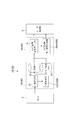
- FIG. 1 is a block diagram showing a schematic configuration of an optimum camera setting apparatus according to Embodiment 1 of the present invention.
- an optimum camera setting device 1 includes a camera 2 for photographing a subject, a store visitor tendency analyzing unit 3, a camera installation state estimating unit 4, and a user presenting unit 5.
- the camera 2 has an image sensor such as a charge coupled device (CCD) or a complementary metal oxide semiconductor (CMOS), and outputs an image captured by the image sensor.
- CCD charge coupled device
- CMOS complementary metal oxide semiconductor
- the store visitor tendency analysis unit 3 includes a person tracking unit 31, a person analysis unit 32, a person unit store visitor information storage unit 33, and a sub area unit store visitor information storage unit 34.
- the person tracking unit 31 detects and tracks a person from the captured image captured by the camera 2.
- the person analysis unit 32 extracts items including face detection count, moving direction, face orientation, focus, dynamic range, and angle of view as store visitor information for the person tracked by the person tracking unit 31.
- the person analysis unit 32 divides the captured image into small areas and generates visitor information for each small area (hereinafter referred to as “sub-area”).
- the visitor information in units of sub areas is information related to the angle of view.
- the person-by-person store visitor information is information related to setting items other than the angle of view (this setting item will be described below).
- the person unit store visitor information storage unit 33 stores store visitor information generated in units of persons.
- the sub area unit store visitor information storage unit 34 stores store visitor information generated in units of sub areas.
- the person unit store visitor information storage unit 33 and the sub area unit store visitor information storage unit 34 are configured by a storage device such as a hard disk or a flash memory.
- a storage device such as a hard disk or a flash memory.
- one storage device constitutes the person unit store visitor information storage unit 33 and the sub area unit store visitor information storage unit 34, but each storage unit 33, 34 may be configured by a dedicated storage device.
- the camera installation state estimation unit 4 uses the visitor information in person units or sub-region units extracted by the person analysis unit 32 of the visitor tendency analysis unit 3 to set the installation position, height, angle of view, and focus of the camera 2.
- the camera installation pass rate calculation unit 41 and the camera installation correction necessity determination unit 42 are included.
- the camera installation pass rate calculation unit 41 sets a pass criterion for the visitor information for each tracking person (that is, in units of persons), and outputs the pass rate as the pass rate.
- the camera installation pass rate calculation unit 41 subdivides the store visitor information for each sub-region (ie, sub-region unit) into the upper half and the lower half of the captured image, and calculates the pass rate with the frequency of the upper half and the lower half. To do.
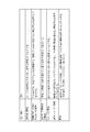
- FIG. 2 is a diagram showing setting and definition of a pass rate in the camera installation pass rate calculating unit 41.
- the pass rate setting items include “number of face frames: threshold”, “movement direction: selection of direction to pass”, “face orientation: threshold of number of front faces”, “focus: OK threshold”,
- the threshold set by “the number of face frames” is, for example, “10”.
- the ratio of the number of persons exceeding the set threshold is output as a pass rate.
- the threshold is “10”
- the ratio of the number of persons exceeding “10” out of 89 persons is output as the pass rate.
- “Moving direction” specifies, for example, a passing direction among eight directions at 180 degrees, and outputs the ratio of the number of persons moving in the specified direction as a passing rate.
- “Face orientation” outputs the ratio of the number of people exceeding the set threshold (number of sheets) as a pass rate.
- the threshold value set for “face orientation” is, for example, “3-5 sheets”.
- “Focus” outputs the ratio of the number of persons exceeding the set threshold (number) as a pass rate.
- the threshold set by “focus” is, for example, “3-5 sheets”.
- the “face D range” determines whether the brightness value range of the face area is OK, and outputs the ratio of the number of people whose OK number exceeds the threshold as a pass rate.
- the threshold value set in the “face D range” is, for example, “3-5 sheets”.
- “View angle” divides an image into two parts, and counts the upper face detection number (Tn) and the lower face detection number (Bn). The pass rate is output as Tn / Bn (1 or more is 1).
- the camera installation correction necessity determination unit 42 uses the acceptance rate calculated by the camera installation acceptance rate calculation unit 41 to determine the installation status including the installation position, height, angle of view, and focus of the camera 2. Which one should be corrected is determined and output to the user presentation unit 5.
- the user presentation unit 5 is output to urge the user to move the camera 2 directly in front of the direction of movement of the person.
- the user presentation unit 5 is prompted to urge the camera 2 to have a wide angle.
- the user presentation unit 5 is prompted to urge the camera 2 to zoom.
- the user presentation unit 5 has a display such as a liquid crystal display, and presents (ie, “displays”) the results and instructions estimated by the camera installation state estimation unit 4.
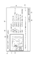
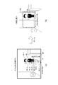
- FIG. 3 is a diagram illustrating an example of a camera installation screen displayed on the user presentation unit 5.
- the camera installation screen 60 includes a live image (real-time image captured by the camera 2) 61, an analysis result 62, a correction plan 63, and a START button for starting a face recognition camera installation test. 64, a STOP button 65 for completing the face recognition camera installation test, a pass rate setting button 66 for setting a pass rate, and an analysis result detail button 67 for displaying details of the analysis result. Is done.
- a face frame 70 and a flow line 71 are superimposed on the live video 61.
- the START button 64 By pressing the START button 64, for example, photographing is performed for 10 minutes. After shooting for 10 minutes, the analysis results of the number of people who visited the store for 10 minutes (for example, the 89 people mentioned above) are displayed with a pass rate. In addition, about the passed item, the numerical value of a pass rate is displayed by the character (for example, red) of a specific color. In the example of FIG. 3, the three items “number of face frames”, “focus”, and “face D range” pass (that is, the installation by the installer is good). If the analysis is performed and there is an unacceptable item, an advice for passing is displayed as a correction plan 63. In the example of FIG. 3, “movement direction”, “face orientation”, and “view angle” are rejected. However, if “face orientation” and “view angle” are zoomed, the acceptance rate is improved. The advice is displayed as a revision proposal 63. Note that the STOP button 65 is pressed to stop shooting halfway.
- FIGS. 4A to 4C are schematic diagrams showing a pass rate calculation procedure in the camera installation pass rate calculating unit 41.
- FIG. 4A first, as shown in FIG. 4A, the flow line 71 is extracted using the face frame 70 set for the store visitor 80 (step 1).
- FIG. 4A shows a case in which a total of seven face frames 70 can be acquired, and a flow line 71 is obtained by linking them.
- the face orientation, focus (focus), and face D range are calculated for each face frame 70 (step 2).
- face orientation information such as left, right, front, etc. is acquired using face orientation estimation, which is an existing technology.
- the focus value for the face area is calculated using an algorithm used in ABF (Auto Back Focus) or the like. Numerical values “100” and “50” shown in the figure are focus values, and the higher the numerical value, the more the focus is achieved.
- the brightness value range is calculated for a region slightly inside the face frame.
- step 4 the pass rate of each item is calculated (step 4).
- the corresponding region is determined based on the center of gravity of the face frame.
- the pass rate is calculated as the cumulative value of all face frames.
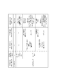
- FIG. 5 is a diagram illustrating an example of camera installation correction necessity determination in the camera installation correction necessity determination unit 42.
- the ratio of the number of face frames exceeding the threshold corresponds to the number of face frames.
- the “number of persons by direction (including direction)” corresponds to the moving direction and direction.
- the “face detection frequency map for each sub region” and “the average face detection size for each sub region” correspond to the angle of view.
- ratio M% in the figure corresponds to the pass rate. The ratio M% is 80%, for example.
- “Period ratio exceeding number of face frames threshold” is less than M%, and “Percentage of persons by direction” is “Up ⁇ Down: Many” (that is, the visitor moves from the upper half to the lower half of the captured image) If the frequency of the upper half area of the captured image is high (approx. Face can be taken only at the entrance), or if the face detection size of the upper half area of the captured image is other than large, the camera installation will be corrected. It is instructed to change the position of the camera 2 as necessary. In this case, since the depression angle (face orientation) of the camera 2 is large, for example, an instruction is given to reduce the height of the camera 2 and increase the distance between the camera and the entrance.
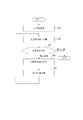
- FIG. 6 is a flowchart showing the installation procedure of the camera 2.
- the camera 2 is temporarily installed (step S1).
- the operation of the optimum camera setting device 1 is started.
- the store visitor tendency analysis unit 3 collects store visitor tendencies (step S2). That is, the person tracking unit 31 detects and tracks a person from the captured image captured by the camera 2, and the person analysis unit 32 detects the number of face detections and the moving direction for the person tracked by the person tracking unit 31. Items including face orientation, focus, dynamic range, and angle of view are extracted as store visitor information.
- the person analysis unit 32 divides the captured image into small areas to generate visitor information for each sub-area, and the generated visitor information for each person
- the store visitor information storage unit 33 stores the store visitor information generated in units of sub-areas in the sub-area unit store visitor information storage unit 34.
- the camera installation state estimation unit 4 uses the visitor information in units of persons or sub areas extracted by the visitor tendency analysis unit 3 to It is estimated whether the installation situation including the installation position, height, angle of view, and focus is suitable, and it is determined whether there is an item that needs correction from the estimation result (step S3). In this determination, if there is no item that requires correction (that is, if correction is not necessary), the present processing is finished. If there is an item that requires correction (that is, if correction is required), the user presenting unit 5 installs the camera 2. A correction proposal is presented (step S4).
- the user presentation unit 5 presents the installation correction proposal for the camera 2
- the user that is, the “constructor”
- the store visitor tendency analysis unit 3 collects store visitor trends again.
- the user performs readjustment of the camera 2 according to the installation correction plan instructed each time until the pass rate can be achieved for all items.
- the camera 2 can be easily set to the optimum position compared to the conventional technology that has been adjusted through trial and error. The work efficiency can be improved.
- the camera 2 that captures the subject
- the person tracking unit 31 that detects and tracks the person from the captured image captured by the camera 2
- the person tracking unit A person analysis unit 32 that extracts items including face detection count, moving direction, face orientation, focus, dynamic range, and angle of view as visitor information for the person tracked in 31, and the person analysis unit 32
- the camera installation status estimation unit 4 that estimates whether the installation status including the installation position, height, angle of view, and focus of the camera 2 is appropriate, and the camera installation status estimation unit 4
- a user presentation unit 5 for presenting the result of the measurement, so that the installation status including the installation position, height, angle of view, and focus of the camera 2 that is most suitable for image recognition processing such as face matching and age gender estimation can be shown to the user.
- Present Bets can be a user, the installation position of the camera 2, the height, angle, it is possible to easily configure focus etc., thereby improving the working efficiency.
- the camera installation / correction necessity determination unit 42 may output to the user presentation unit 5 a message prompting the user to change the resolution and frame rate of the camera 2. .
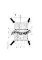
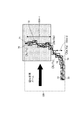
- FIG. 7 (a) and 7 (b) are diagrams showing an example in which the resolution / frame rate is presented as a correction proposal.
- (A) of the figure is an image of the vicinity including the entrance of the store, the resolution is 4VGA (1280 ⁇ 960 pixels), and the frame rate is 5 fps.
- the face frame of the visitor 80 is the front face, four face frames (70-1 to 70-4), one side face (70-5), and two downward faces ( 70-6, 70-7) When obtained, as a tendency of this store, it is difficult to take a front face in the section indicated by the arrow 90.
- an area where the face of the visitor 80 is in front is calculated, and the position, resolution, and frame rate for photographing the area are determined.
- the frame rate is 20 fps when VGA (640 ⁇ 480 pixels) is used.
- the area is long (that is, when the area is large), 4 VGA and frame rate is 5 fps (as it is).
- a view angle image to be changed is presented.
- FIG. 7B shows an image of the angle of view.
- a square denoted by reference numeral 100 is a new angle of view (a zoomed-in angle of view). Under the new angle of view 100, the characters “VGA, 20 fps” are displayed. The user can make settings so that the front face of the visitor 80 can be obtained with certainty by adjusting according to this instruction.
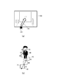
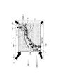
- FIGS. 8A and 8B are diagrams illustrating an example in which a correction proposal is presented using an image.
- the zoom magnification is clearly shown using an image. This corresponds to indicating the frame of the new angle of view 100 shown in FIG.
- an arrow 110 and a star 111 opposite to the main movement direction of the store visitor are superimposed and displayed on the photographed image.
- the star 111 indicates the position of the camera 2, and the front face of the visitor can be easily taken by turning the camera 2 upward.
- the magnification for wide angle is determined based on the number of pixels to be displayed closest to the face frame 70 (the number of pixels in the face frame 70 is 30, 32, 36,). For example, when the minimum size of face recognition (minimum value for face recognition) is “20”, the wide angle is set to 1.5 times.
- the remaining number of corrections may be presented. For example, if it is determined that the movement direction is oblique, the remaining number of corrections is set to three. In this case, the first time corrects the camera position, the second time corrects the angle of view (tilt), and the third time corrects the angle of view (zoom).
- the hardware configuration of the store visitor tendency analysis unit 3 and the camera installation state estimation unit 4 includes a CPU (central processing unit), a volatile memory such as a RAM, a ROM, and the like.
- a computer having a non-volatile memory and an interface can be used.
- a program describing the functions of the optimum camera setting device 1 according to the present embodiment can be stored and distributed in a storage medium such as a magnetic disk, a hard disk, an optical disk, a magneto-optical disk, or a semiconductor memory.
- FIG. 9 is a block diagram showing a schematic configuration of the optimum camera setting apparatus according to Embodiment 2 of the present invention.
- the optimal camera setting device 1A includes a camera 2 that captures a shooting range, a store visitor tendency analysis unit 3A, a shooting range determination unit (shooting range determination means) 4A, and a user presentation unit. 5.
- the camera 2 has an image sensor such as a CCD or CMOS, and outputs an image captured by the image sensor.
- the store visitor tendency analysis unit 3A includes a person tracking unit 31, a person analysis unit 32A, a person unit store visitor information storage unit 33, and a sub area unit store visitor information storage unit 34.
- the person tracking unit 31 detects and tracks a person from the captured image captured by the camera 2.
- the person analysis unit (flow line extraction unit, face direction detection unit) 32A obtains the flow line of the person for the person tracked by the person tracking unit 31. Also, the person analysis unit 32A extracts items including face detection count, movement direction, face orientation, focus, dynamic range, and angle of view as store visitor information for a person who moves along the flow line.
- the person analysis unit 32A divides the captured image into small areas and generates visitor information for each small area (hereinafter referred to as “sub-area”).
- the visitor information in units of sub areas is information related to the angle of view.
- the person-by-person store visitor information is information related to setting items other than the angle of view (this setting item will be described below).
- the person unit store visitor information storage unit 33 stores store visitor information generated in units of persons.
- the sub area unit store visitor information storage unit 34 stores store visitor information generated in units of sub areas.
- the person unit store visitor information storage unit 33 and the sub area unit store visitor information storage unit 34 are configured by a storage device such as a hard disk or a flash memory.
- a storage device such as a hard disk or a flash memory.
- one storage device constitutes the person unit store visitor information storage unit 33 and the sub area unit store visitor information storage unit 34, but each storage unit 33, 34 may be configured by a dedicated storage device.
- the shooting range determination unit 4A includes a camera installation pass rate calculation unit 41 and a camera installation correction necessity determination unit 42A, and is a person unit or sub-region unit extracted by the person analysis unit 32A of the store visitor tendency analysis unit 3A. Is used to estimate whether the installation position including the installation position, height, angle of view, and focus of the camera 2 is suitable, and from the front face ratio and the front face position in the flow line 2 is determined.
- the camera installation pass rate calculation unit 41 sets a pass criterion for the visitor information for each tracking person (that is, in units of persons), and outputs the pass rate as the pass rate.
- the camera installation pass rate calculation unit 41 subdivides the store visitor information for each sub-region (ie, sub-region unit) into the upper half and the lower half of the captured image, and calculates the pass rate with the frequency of the upper half and the lower half. To do.
- the camera installation correction necessity determination unit 42A performs the same operation as the camera installation correction necessity determination unit 42 of the optimum camera setting device 1 according to Embodiment 1 described above, and the front face ratio and the front in the flow line.
- the shooting range of the camera 2 is determined from the position of the face.
- the user presenting unit (presenting means) 5 has a display such as a liquid crystal display, and presents (that is, “displays”) the photographing range determined by the photographing range determining unit 4A.
- the front face is defined as shown in FIG. That is, the range is 30 degrees from the center of the face, and if the face is reflected within this range, the front face is determined.
- the flow line 71 is obtained by averaging the flow lines 71-1, 71-2,..., 71-100 of a plurality of persons (about 100 persons).
- the number of face images in which the face of a person moving along the flow line 71 (including the front face) is detected is an average of the number of faces of the person moved along the flow line 71 detected by the person analysis unit 32A.
- “ ⁇ ” indicates the face frame 70.
- the ratio of the front face in the flow line 71 and the range 100A including the front face are calculated, and the start point (Xs, Ys) and end point (Xe, Ye) of the front face are calculated.
- the ratio of the front face in the flow line 71 is the ratio of the front face to all the face frames 70.
- FIG. 12 shows the case where the ratio of the front face is 80% or less and there is one range 100A including the front face. It is the figure which showed typically operation
- the arrow 72 shown in the drawing indicates the face direction.
- the shooting range of the camera 2 is set to the range 100A.
- the shooting range of the camera 2 is set to the range 100A.
- FIG. 13 is a diagram schematically showing an operation when the face frame number Nf is less than the threshold value Nt.
- the number of face frames Nf is the threshold value Nt (“5”). ).
- an upward arrow 130 is shown so that the camera 2 faces upward, and an adbus “turn the camera upward” is performed below the arrow 130.
- an adbus “turn the camera upward” is performed below the arrow 130.
- the lower side of the shooting range of the camera 2 is the range 100A.
- FIG. 14 shows the number of face frames when the ratio of the front face is 80% or less and there are a plurality of ranges including the front face. It is the figure which showed typically the operation
- An arrow 72 shown in the figure indicates the direction of the face. In each of the two front face ranges 100A-1 and 100A-2, the face frame number Nf of the front face is calculated.
- the threshold value Nt is “5”
- the range where the face frame number Nf is equal to or greater than the threshold value Nt is only the range 100A-1.
- advice is given to zoom up from the front face start point (Xs, Ys) to the end point (Xe, Ye) in the front face range 100A-1. That is, the original angle of view 120 is narrowed so that the five front faces from the start point (Xs, Ys) to the end point (Xe, Ye) can be taken large. In this case, zooming is performed while shifting the original angle of view 120 to the right.
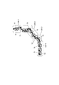
- 15 is a diagram schematically showing an operation in the case where the ratio of the front face is 80% or less and there are a plurality of ranges including the front face, and the number Nf of the face frames of all the front faces is less than the threshold value Nt. is there.
- An arrow 72 shown in the figure indicates the direction of the face.
- the total number of face frames in the flow line 71 is “10”
- the number Nf of front face frames in the front face range 100A-1 is “2”
- the front face range 100A-2 Since the number Nf of the face frame of the front face is “2”, the ratio of the front face is 20% in both the front face ranges 100A-1 and 100A-2, and both satisfy the condition of 80% or less. Since the threshold value Nt is “5”, the face frame number Nf is less than the threshold value Nt in both the front face ranges 100A-1 and 100A-2.
- zooming is performed so that the range from (Xs, Ys) closest to the start point 71a of the flow line 71 to (Xe, Ye) closest to the end point 71b of the flow line 71 is in the range 100-5.
- the original angle of view 120 so that ten front faces from (Xs, Ys) closest to the start point 71a of the flow line 71 to (Xe, Ye) closest to the end point 71b of the flow line 71 can be taken. To narrow.
- the camera The advice is given so that the two shooting ranges are from the uppermost section to the lowermost section of the two or more ranges.
- the optimal camera setting device 1A there is one range 100A in which the face direction of a person is a front face, and the number of front face frames Nf in the range 100A is equal to or greater than the threshold value Nt.
- advice is given so that the shooting range of the camera 2 is set to the range 100A.
- the number Nf of front face frames in the range 100A is less than the threshold value Nt, the lower side of the shooting range of the camera 2 is set to the lower side of the range 100A.
- the face direction of the person is the front face
- the front face in any one of the two or more ranges 100A-1 and 100A-2
- the number of face frames Nf is equal to or greater than the threshold value Nt
- advice is given so that the range is the shooting range of the camera 2, and the person is in any of the two or more ranges 100A-1 and 100A-2.
- the shooting range of the camera 2 is the lowest zone from the highest zone of the shooting range in the two or more ranges 100A-1 and 100A-2. Since the advice is given so that it can be taken, more front faces can be taken. When used as a surveillance camera, performance can be improved.
- the CPU central processing unit
- a volatile memory such as a RAM
- a nonvolatile memory such as a ROM
- a computer equipped with a memory and an interface can be used.
- a program describing the functions of the optimum camera setting device 1A according to the present embodiment can be stored and distributed in a storage medium such as a magnetic disk, a hard disk, an optical disk, a magneto-optical disk, or a semiconductor memory.
- the camera adjustment advice is given based on the ratio of the front face and the position of the front face in the flow line 71.
- the optimum camera setting according to the present embodiment is described.
- the device advises the position to focus on from the focus and face orientation. Since the configuration of the optimal camera setting device according to the present embodiment is the same as that of the optimal camera setting device 1A according to the second embodiment, FIG.
- reference numeral 1B is assigned to the optimum camera setting device according to the present embodiment.
- reference numeral 4B is assigned to the shooting range determination unit of the optimum camera setting device according to the present embodiment.
- reference numeral 42B is assigned to the camera installation correction necessity determination unit of the photographing range determination unit 4B. Further, 3B is assigned to the visitor tendency analysis unit, and 32B is assigned to the person analysis unit (flow line dividing means) of the visitor tendency analysis unit 3B.
- the focus value and the face orientation of all the face frames are calculated, and a position to focus on an area having a good face orientation (that is, a range having a high face orientation pass rate) is advised.
- the focus value indicates the degree of blurring of the image, and is represented by a value of “0 to 255”.
- the value of “0 to 255” increases as the focus is improved. That is, “0” is the lowest and “255” is the highest.
- FIG. 16 is a diagram schematically showing the operation of the optimum camera setting device 1B according to the present embodiment.
- the flow line 71 is first divided into ranges for each degree of face orientation.
- the range analysis of the flow line 71 is performed by the person analysis unit 32B.
- the range is divided into [Range 1] 130-1 to [Range 4] 130-4.
- the face orientation pass rate is “80%”, the average focus value is “85”, the number of face frames is “5”, and in [Range 2] 130-2, the face orientation pass rate is In “60%”, the focus average value is “90”, the number of face frames is “2”, and [Range 3] 130-3, the face orientation pass rate is “95%”, the focus average value is “100”, and the face
- the face orientation pass rate is “50%”, the focus average value is “120”, and the number of face frames is “4”.
- [Range 1] 130-1 to [Range 4] 130-4 [Range 3] 130-3 has the highest face orientation pass rate, followed by [Range 1] 130-1. However, since the number of face frames in [Range 3] 130-3 is as small as “2”, [Range 1] 130-1 with the number of face frames “5” is used. Give advice to focus.
- the flow line 71 is divided according to the degree of the face of the person so that the section in which the degree of the face is close to the front face is in focus. Since the camera 2 is adjusted, more front faces can be taken well.
- the CPU central processing unit
- a volatile memory such as a RAM
- a nonvolatile memory such as a ROM
- a computer equipped with a memory and an interface can be used.
- a program describing the functions of the optimum camera setting device 1B according to the present embodiment can be stored and distributed in a storage medium such as a magnetic disk, a hard disk, an optical disk, a magneto-optical disk, or a semiconductor memory.
- the present invention has the effect of being able to present to the user the installation status including the camera installation position, height, angle of view, and focus optimal for image recognition processing such as face matching and age and gender estimation. It can be applied to surveillance camera systems that are permanently installed in buildings such as stores, banks, and public facilities.
Landscapes
- Engineering & Computer Science (AREA)
- Multimedia (AREA)
- Signal Processing (AREA)
- Theoretical Computer Science (AREA)
- Physics & Mathematics (AREA)
- General Physics & Mathematics (AREA)
- Human Computer Interaction (AREA)
- Health & Medical Sciences (AREA)
- General Health & Medical Sciences (AREA)
- Oral & Maxillofacial Surgery (AREA)
- Software Systems (AREA)
- Computer Vision & Pattern Recognition (AREA)
- Bioinformatics & Computational Biology (AREA)
- Artificial Intelligence (AREA)
- Bioinformatics & Cheminformatics (AREA)
- Life Sciences & Earth Sciences (AREA)
- Data Mining & Analysis (AREA)
- Evolutionary Biology (AREA)
- Evolutionary Computation (AREA)
- General Engineering & Computer Science (AREA)
- Studio Devices (AREA)
- Image Analysis (AREA)
- Closed-Circuit Television Systems (AREA)
Abstract
Description
図1は、本発明の実施の形態1に係る最適カメラ設定装置の概略構成を示すブロック図である。同図において、本実施の形態に係る最適カメラ設定装置1は、被写体を撮影するカメラ2と、来店者傾向分析部3と、カメラ設置状況推定部4と、ユーザ提示部5とを備える。カメラ2は、CCD(Charge Coupled Device)やCMOS(Complementary Metal Oxide Semiconductor)等の撮像素子を有し、該撮像素子で撮像した画像を出力する。 (Embodiment 1)
FIG. 1 is a block diagram showing a schematic configuration of an optimum camera setting apparatus according to
図9は、本発明の実施の形態2に係る最適カメラ設定装置の概略構成を示すブロック図である。なお、同図において前述した図1と共通する部分には同一の符号を付けている。同図に示す本実施の形態に係る最適カメラ設定装置1Aは、撮影範囲を撮影するカメラ2と、来店者傾向分析部3Aと、撮影範囲決定部(撮影範囲決定手段)4Aと、ユーザ提示部5とを備える。カメラ2は、CCDやCMOS等の撮像素子を有し、該撮像素子で撮像した画像を出力する。 (Embodiment 2)
FIG. 9 is a block diagram showing a schematic configuration of the optimum camera setting apparatus according to
動作説明に際し、正面顔を図10に示すように定義する。即ち、顔の中心から左右30度の範囲とし、この範囲内で顔が映っていれば正面顔とする。また、動線71は、図11に示すように、複数人(100人程度)の動線71-1,71-2,…,71-100を平均化したものとする。動線71に沿って移動する人物の顔(正面顔を含む)を検出した顔画像の数は、人物解析部32Aが検出した動線71に沿って移動した人物の顔の枚数の平均である。なお、図11において、“□”は顔枠70を示す。 Next, the operation of the optimum
In describing the operation, the front face is defined as shown in FIG. That is, the range is 30 degrees from the center of the face, and if the face is reflected within this range, the front face is determined. Further, as shown in FIG. 11, the
図12は、正面顔の割合が80%以下、かつ正面顔を含む範囲100Aが1つの場合で、顔枠の数である顔枠数Nfが閾値Nt以上の場合の動作を模式的に示した図である。なお、図中に示す矢印72は顔向きを示している。正面顔の割合が80%以下で、正面顔を含む範囲100Aが1つの場合において、動線71における正面顔の顔枠数Nfを算出する。 [A] When the ratio of the front face is 80% or less and there is one
正面顔の範囲100Aにおける正面顔の始点(Xs,Ys)から終点(Xe,Ye)の領域にズームアップするようにアドバイスを行う。図12に示す場合においては、動線71における全顔枠数が「10個」、正面顔の顔枠数Nfが「7個」となるので、正面顔の割合は70%となり、80%以下の条件を満たす。ここで閾値Ntを「5」とした場合、顔枠数Nfが閾値Nt以上となるので、正面顔の始点(Xs,Ys)から終点(Xe,Ye)の領域にズームアップするようにアドバイスを行う。即ち、始点(Xs,Ys)から終点(Xe,Ye)までの7つの正面顔を大きく撮れるように、元々の画角120を狭める。 (A) When the calculated face frame number Nf is equal to or greater than the threshold value Nt Advice is given to zoom up from the front face start point (Xs, Ys) to the end point (Xe, Ye) in the
上記(a)は、顔枠数Nfが閾値Nt以上の場合であったが、顔枠数Nfが閾値Nt未満の場合、正面顔の終点(Xe,Ye)が画面下側に来るようにカメラ2を上に向けるようにアドバイスを行う。図13は、顔枠数Nfが閾値Nt未満の場合の動作を模式的に示した図である。同図において、動線71における全顔枠数が「10個」で、正面顔の範囲100Aでの顔枠数Nfが「3個」であるので、顔枠数Nfは閾値Nt(「5」)未満である。このような場合、カメラ2を上に向けるように、上向きの矢印130を示すとともに、その下側に「カメラを上向きにする」というアドバスを行う。例えば、店舗に設置した監視カメラにおいて、画角120の上側が入口になる場合、入口の方が正面顔を多く撮れる確率が高いので、カメラ2を上向きにするようにアドバイスを行うことで、正面顔を多く撮ることができるようになる。 (B) When the calculated face frame number Nf is less than the threshold value Nt The above (a) is a case where the face frame number Nf is greater than or equal to the threshold value Nt, but when the face frame number Nf is less than the threshold value Nt, Advice is given to point the
図14は、正面顔の割合が80%以下、かつ正面顔を含む範囲が複数ある場合で、顔枠数Nfが閾値Nt以上の場合の動作を模式的に示した図である。なお、図中に示す矢印72は顔の向きを示している。2つの正面顔の範囲100A-1,100A-2それぞれにおいて正面顔の顔枠数Nfを算出する。 [B] When the ratio of the front face is 80% or less and there are a plurality of ranges including the front face FIG. 14 shows the number of face frames when the ratio of the front face is 80% or less and there are a plurality of ranges including the front face. It is the figure which showed typically the operation | movement in case Nf is more than the threshold value Nt. An
2つの正面顔の範囲100A-1,100A-2それぞれにおける顔枠数Nfの算出後、閾値Nt以上の範囲がある場合、当該範囲の領域にズームアップするようにアドバイスを行う。図14に示す場合においては、動線71における全顔枠数が「13個」、正面顔の範囲100A-1における正面顔の顔枠数Nfが「5個」、正面顔の範囲100A-2における正面顔の顔枠数Nfが「2個」となるので、正面顔の範囲100A-1における正面顔の割合は約38.5%、正面顔の範囲100A-2における正面顔の割合は約15.4%となり、いずれも80%以下の条件を満たす。しかし、閾値Ntは「5」であるので、顔枠数Nfが閾値Nt以上の範囲は範囲100A-1のみとなる。このような場合、正面顔の範囲100A-1における正面顔の始点(Xs,Ys)から終点(Xe,Ye)の領域にズームアップするようにアドバイスを行う。即ち、始点(Xs,Ys)から終点(Xe,Ye)までの5つの正面顔を大きく撮れるように、元々の画角120を狭める。この場合、元々の画角120を右にずらしながらズームする。 (C) When the calculated face frame number Nf is in a range greater than or equal to the threshold value Nt After calculating the face frame number Nf in each of the two front face ranges 100A-1 and 100A-2, Advise to zoom up to the area of the range. In the case shown in FIG. 14, the total number of face frames in the
動線71の始点71aに一番近い(Xs,Ys)から、動線71の終点71bに一番近い(Xe,Ye)までを範囲とするようにズームアップするアドバイスを行う。即ち、元々の画角120に対する正面顔の割合を増やすためのアドバイスを行う。なお、言うまでもないが、正面顔の割合を増やすためのアドバイスは、上述した(a)~(c)においても同様である。図15は、正面顔の割合が80%以下、かつ正面顔を含む範囲が複数ある場合で、全ての正面顔の顔枠数Nfが閾値Nt未満の場合の動作を模式的に示した図である。なお、図中に示す矢印72は顔の向きを示している。 (D) When the number Nf of face frames of all front faces is less than the threshold Nt From (Xs, Ys) closest to the
前述した実施の形態2に係る最適カメラ設定装置1Aでは、動線71における正面顔の割合と正面顔の位置からカメラ調整のアドバイスを行うものであったが、本実施の形態に係る最適カメラ設定装置では、ピントと顔向きからピントを合わせる位置をアドバイスするものである。本実施の形態に係る最適カメラ設定装置の構成は、実施の形態2に係る最適カメラ設定装置1Aと同様であるので、図9を援用する。また、本実施の形態に係る最適カメラ設定装置には符号1Bを付与する。また、本実施の形態に係る最適カメラ設定装置の撮影範囲決定部には符号4Bを付与する。また、撮影範囲決定部4Bのカメラ設置修正要否判定部には符号42Bを付与する。また、来店者傾向分析部には3Bを付与し、来店者傾向分析部3Bの人物解析部(動線分割手段)には符号32Bを付与する。 (Embodiment 3)
In the optimal
2 カメラ
3、3A,3B 来店者傾向分析部
4 カメラ設置状況推定部
4A,4B 撮影範囲決定部
5 ユーザ提示部
31 人物追跡部
32,32A,32B 人物解析部
33 人物単位来店者情報記憶部
34 サブ領域単位来店者情報記憶部
41 カメラ設置合格率算出部
42,42A,42B カメラ設置修正要否判定部
60 カメラ設置画面
70 顔枠
71 動線
72 顔向き
80 来店者
100A,100A-1,100A-2 正面顔の範囲
130-1~130-4 範囲 1, 1A, 1B Optimal
Claims (19)
- 被写体を撮影するカメラで撮影された撮影画像から人物を検出し追跡する人物追跡手段と、
前記人物追跡手段で追跡された人物に対して、少なくとも顔の検出回数、顔向き、画角のいずれか一つを来店者情報として抽出する人物解析手段と、
前記人物解析手段で抽出された来店者情報を用いて、前記カメラの設置状況が適しているかを推定するカメラ設置状況推定手段と、
を備えたことを特徴とする最適カメラ設定装置。 A person tracking means for detecting and tracking a person from a photographed image taken by a camera for photographing a subject;
A person analyzing means for extracting at least one of the number of times of face detection, the face orientation, and the angle of view as store visitor information for the person tracked by the person tracking means;
Using the store visitor information extracted by the person analysis means, camera installation status estimation means for estimating whether the camera installation status is suitable;
An optimal camera setting device characterized by comprising: - 前記カメラ設置状況推定手段は、人物の移動方向の合格率が低い場合、該人物の移動方向の真正面に前記カメラを移動するように促す旨を提示することを特徴とする請求項1記載の最適カメラ設定装置。 2. The optimum according to claim 1, wherein the camera installation state estimation means presents an instruction to move the camera directly in front of the movement direction of the person when the pass rate in the movement direction of the person is low. Camera setting device.
- 前記人物解析手段は、追跡人物毎の来店者情報に加えて、撮像画像を小領域に分割して小領域毎に来店者情報を生成することを特徴とする請求項1記載の最適カメラ設定装置。 2. The optimum camera setting device according to claim 1, wherein the person analysis means divides the captured image into small areas in addition to the store visitor information for each tracked person and generates store visitor information for each small area. .
- 前記カメラ設置状況推定手段は、前記小領域毎の来店者情報を撮影画像の上半分と下半分に再分割し、上半分と下半分の頻度で合格率を算出することを特徴とする請求項3記載の最適カメラ設定装置。 The camera installation state estimating means subdivides the visitor information for each small area into an upper half and a lower half of the captured image, and calculates a pass rate with a frequency of the upper half and the lower half. 3. The optimum camera setting device according to 3.
- 前記カメラ設置状況推定手段は、顔の検出回数が前記撮影画像の下半分より上半分に多くあるとき、前記カメラを広角にするように促す旨を提示することを特徴とする請求項4記載の最適カメラ設定装置。 The said camera installation condition estimation means presents the fact that the camera is urged to have a wide angle when the number of face detections is larger than the lower half of the captured image. Optimal camera setting device.
- 前記カメラ設置状況推定手段は、顔の検出回数が前記撮影画像の上半分より下半分に多くあるとき、前記カメラをズームするように促す旨を提示することを特徴とする請求項4記載の最適カメラ設定装置。 5. The optimal setting according to claim 4, wherein the camera installation state estimation means presents an instruction to zoom the camera when the number of face detections is larger in the lower half than the upper half of the captured image. Camera setting device.
- 前記カメラ設置状況推定手段は、追跡人物毎の来店者情報に合格基準を設け、前記合格基準を超えた人数比率を合格率として出力することを特徴とする請求項1記載の最適カメラ設定装置。 The optimal camera setting device according to claim 1, wherein the camera installation state estimating means sets a pass criterion for visitor information for each tracking person, and outputs a ratio of the number of persons exceeding the pass criterion as a pass rate.
- 前記カメラ設置状況推定手段は、前記合格率を用いて、前記カメラの設置位置、高さ、画角、フォーカスを含む設置状況のいずれを修正すべきかを判定して出力することを特徴とする請求項4記載の最適カメラ設定装置。 The camera installation status estimation means determines and outputs which of the installation status including the installation position, height, angle of view, and focus of the camera should be corrected using the acceptance rate. Item 5. The optimum camera setting device according to Item 4.
- 前記カメラ設置状況推定手段は、前記カメラの解像度、フレームレートの変更を促す旨を提示することを特徴とする請求項5記載の最適カメラ設定装置。 6. The optimum camera setting device according to claim 5, wherein the camera installation state estimation means presents an instruction to change the resolution and frame rate of the camera.
- 被写体を撮影するカメラで撮影された撮影画像から人物を検出し追跡する人物追跡ステップと、
前記人物追跡ステップで追跡された人物に対して、顔の検出回数、顔向き、画角を来店者情報として抽出する人物解析ステップと、
前記人物解析ステップで抽出された来店者情報を用いて、前記カメラの設置状況が適しているかを推定するカメラ設置状況推定ステップと、
を備えたことを特徴とする最適カメラ設定方法。 A person tracking step for detecting and tracking a person from a photographed image taken by a camera for photographing a subject;
A person analysis step for extracting the number of face detections, face orientation, and angle of view as visitor information for the person tracked in the person tracking step;
Using the store visitor information extracted in the person analysis step, a camera installation state estimation step for estimating whether the camera installation state is suitable;
An optimal camera setting method characterized by comprising: - 撮影範囲を撮影するカメラで撮影した人物の画像から前記人物を追跡して前記人物の動線を求める動線抽出手段と、
前記動線を移動する前記人物の顔向きを検出する顔向き検出手段と、
前記顔向き検出手段が検出した前記人物の顔向きが正面顔の前記動線の区間が一つであって、
前記区間の前記正面顔の枚数が所定の枚数以上のとき、前記カメラの撮影範囲を前記正面顔が検出された区間になるように変更することを決定し、
前記区間の前記正面顔の枚数が所定の枚数より少ないとき、前記カメラの前記撮影範囲の下側を前記正面顔が検出された区間の範囲の下側になるように変更することを決定する撮影範囲決定手段と、
前記撮影範囲決定手段によって決定された撮影範囲を提示する提示手段と、を有することを特徴とする最適カメラ設定装置。 A flow line extraction means for tracking the person from the image of the person photographed by the camera for photographing the photographing range and obtaining the flow line of the person;
Face orientation detection means for detecting the face orientation of the person moving along the flow line;
The face direction of the person detected by the face direction detecting means is one section of the flow line of the front face,
When the number of front faces in the section is equal to or greater than a predetermined number, it is determined that the shooting range of the camera is changed to be a section in which the front face is detected;
When the number of front faces in the section is less than a predetermined number, shooting that determines to change the lower side of the shooting range of the camera to be lower than the range of the section in which the front face is detected A range determination means;
An optimum camera setting device comprising: presenting means for presenting a photographing range determined by the photographing range determining means. - 前記顔向き検出手段が検出した前記動線に沿って移動する人物の正面顔の割合が所定の割合以下のとき、前記撮影範囲決定手段が前記撮影範囲の変更を行うことを特徴とする請求項11に記載の最適カメラ設定装置。 The imaging range determination unit changes the imaging range when a ratio of a front face of a person moving along the flow line detected by the face direction detection unit is equal to or less than a predetermined rate. The optimum camera setting device according to 11.
- 前記顔向き検出手段が検出した前記人物の顔向きが正面顔の前記動線の区間が二つ以上であって、
前記二つ以上の区間のいずれか一つの区間について前記人物の正面顔が検出された画像の枚数が所定の枚数以上のとき、
前記撮影範囲決定手段は、前記カメラの撮影範囲を前記二つ以上の区間のいずれか一つの区間になるように変更することを決定することを特徴とする請求項11または請求項12に記載の最適カメラ設定装置。 The face direction of the person detected by the face direction detection means is two or more sections of the flow line of the front face,
When the number of images in which the front face of the person is detected in any one of the two or more sections is a predetermined number or more,
The said imaging | photography range determination means determines changing the imaging | photography range of the said camera so that it may become any one of the said 2 or more area, The Claim 11 or Claim 12 characterized by the above-mentioned. Optimal camera setting device. - 前記顔向き検出手段が検出した前記人物の顔向きが正面顔の前記動線の区間が二つ以上であって、
前記二つ以上の区間のいずれの区間についても前記人物の正面顔が検出された画像の枚数が所定の枚数より少ないとき、
前記撮影範囲決定手段は、前記撮影範囲を前記二つ以上の区間の中で前記撮影範囲の最も上にある区間から最も下にある区間までに前記撮影範囲を設定することを特徴とする請求項11または請求項12に記載の最適カメラ設定装置。 The face direction of the person detected by the face direction detection means is two or more sections of the flow line of the front face,
When the number of images in which the front face of the person is detected in any of the two or more sections is less than a predetermined number,
The imaging range determining means sets the imaging range from the uppermost section to the lowermost section of the imaging range in the two or more sections. The optimal camera setting apparatus of Claim 11 or Claim 12. - 前記顔向き検出手段が検出した前記人物の顔向きの程度に合わせて前記動線を分割する動線分割手段を有し、
前記撮影範囲決定手段は、前記顔向きの程度が正面顔に近い区間が合焦するように前記カメラを調整することを特徴とする請求項11に記載の最適カメラ設定装置。 Flow line dividing means for dividing the flow line in accordance with the degree of face orientation of the person detected by the face direction detecting means;
The optimal camera setting device according to claim 11, wherein the photographing range determination unit adjusts the camera so that a section in which the degree of face orientation is close to a front face is in focus. - 前記撮影範囲決定手段は、前記顔向きが正面顔に近い区間であって正面顔の枚数が多い区間に合焦するように前記カメラを調整することを特徴とする請求項15に記載の最適カメラ設定装置。 16. The optimum camera according to claim 15, wherein the photographing range determining means adjusts the camera so that the camera is focused on a section in which the face direction is close to the front face and the number of front faces is large. Setting device.
- 前記人物の正面顔が検出された画像の枚数は、前記顔向き検出手段が検出した前記動線に沿って移動した人物の正面顔が検出された枚数の平均であることを特徴とする請求項11乃至請求項16のいずれか一項に記載の最適カメラ設定装置。 The number of images in which the front face of the person is detected is an average of the number of images in which the front face of the person moved along the flow line detected by the face direction detecting means is detected. The optimal camera setting device according to any one of claims 11 to 16.
- 前記動線に沿って移動する人物の顔を検出した顔画像の数は、前記顔向き検出手段が検出した前記動線に沿って移動した人物の顔の枚数の平均であることを特徴とする請求項11乃至請求項16のいずれか一項に記載の最適カメラ設定装置。 The number of face images in which the face of a person moving along the flow line is detected is an average of the number of faces of the person moved along the flow line detected by the face direction detecting means. The optimum camera setting device according to any one of claims 11 to 16.
- 計算機を用いてカメラの設定を表示する最適カメラ設定方法であって、
撮影範囲を撮影する撮影ステップと、
前記撮影ステップで撮影した人物の画像から前記人物を追跡して前記人物の動線を求める動線抽出ステップと、
前記動線を移動する前記人物の顔向きを検出する顔向き検出ステップと、
前記顔向き検出ステップで検出した前記人物の顔向きが正面顔の前記動線の区間が一つであって、
前記区間の前記正面顔の枚数が所定の枚数以上のとき、前記撮影ステップの撮影範囲を前記正面顔が検出された区間になるように変更することを決定し、
前記区間の前記正面顔の枚数が所定の枚数より少ないとき、前記撮影ステップの前記撮影範囲の下側を前記正面顔が検出された区間の範囲の下側になるように変更することを決定する撮影範囲決定ステップと、
前記撮影範囲決定ステップによって決定された撮影範囲を提示する提示ステップと、を有することを特徴とする最適カメラ設定方法。 An optimal camera setting method for displaying camera settings using a computer,
A shooting step for shooting the shooting range;
A flow line extraction step of tracking the person from the image of the person photographed in the photographing step to obtain a flow line of the person;
A face direction detecting step for detecting a face direction of the person moving along the flow line;
The face direction of the person detected in the face direction detection step is one section of the flow line of the front face,
When the number of front faces in the section is a predetermined number or more, it is determined to change the shooting range of the shooting step to be a section in which the front face is detected,
When the number of front faces in the section is less than a predetermined number, it is determined to change the lower side of the shooting range in the shooting step to be lower than the range of the section in which the front face is detected. A shooting range determination step;
And a presentation step for presenting the photographing range determined by the photographing range determination step.
Priority Applications (3)
| Application Number | Priority Date | Filing Date | Title |
|---|---|---|---|
| JP2013556261A JP5958716B2 (en) | 2012-01-30 | 2013-01-29 | Optimal camera setting device and optimal camera setting method |
| US14/374,544 US9781336B2 (en) | 2012-01-30 | 2013-01-29 | Optimum camera setting device and optimum camera setting method |
| EP20130744190 EP2811736A4 (en) | 2012-01-30 | 2013-01-29 | Optimum camera setting device and optimum camera setting method |
Applications Claiming Priority (2)
| Application Number | Priority Date | Filing Date | Title |
|---|---|---|---|
| JP2012-016700 | 2012-01-30 | ||
| JP2012016700 | 2012-01-30 |
Publications (1)
| Publication Number | Publication Date |
|---|---|
| WO2013114862A1 true WO2013114862A1 (en) | 2013-08-08 |
Family
ID=48904909
Family Applications (1)
| Application Number | Title | Priority Date | Filing Date |
|---|---|---|---|
| PCT/JP2013/000468 WO2013114862A1 (en) | 2012-01-30 | 2013-01-29 | Optimum camera setting device and optimum camera setting method |
Country Status (4)
| Country | Link |
|---|---|
| US (1) | US9781336B2 (en) |
| EP (1) | EP2811736A4 (en) |
| JP (1) | JP5958716B2 (en) |
| WO (1) | WO2013114862A1 (en) |
Cited By (5)
| Publication number | Priority date | Publication date | Assignee | Title |
|---|---|---|---|---|
| JP2015195459A (en) * | 2014-03-31 | 2015-11-05 | オムロン株式会社 | Setting abnormality determination device and program |
| JP2016143157A (en) * | 2015-01-30 | 2016-08-08 | キヤノン株式会社 | Image processing device, image processing method and image processing system |
| US10063967B2 (en) | 2016-03-22 | 2018-08-28 | Panasonic Intellectual Property Management Co., Ltd. | Sound collecting device and sound collecting method |
| US10771716B2 (en) | 2018-03-29 | 2020-09-08 | Kyocera Document Solutions Inc. | Control device, monitoring system, and monitoring camera control method |
| JPWO2019239744A1 (en) * | 2018-06-11 | 2021-08-26 | パナソニックIpマネジメント株式会社 | Imaging control device, imaging control method, and program |
Families Citing this family (8)
| Publication number | Priority date | Publication date | Assignee | Title |
|---|---|---|---|---|
| JP6273685B2 (en) | 2013-03-27 | 2018-02-07 | パナソニックIpマネジメント株式会社 | Tracking processing apparatus, tracking processing system including the tracking processing apparatus, and tracking processing method |
| JP6206804B2 (en) | 2013-09-27 | 2017-10-04 | パナソニックIpマネジメント株式会社 | Mobile object tracking device, mobile object tracking system, and mobile object tracking method |
| JP6128468B2 (en) * | 2015-01-08 | 2017-05-17 | パナソニックIpマネジメント株式会社 | Person tracking system and person tracking method |
| US9165461B1 (en) * | 2015-05-06 | 2015-10-20 | Intellectual Fortress, LLC | Image processing based traffic flow control system and method |
| JP6865351B2 (en) * | 2015-07-27 | 2021-04-28 | パナソニックIpマネジメント株式会社 | Face matching device and face matching system equipped with this and face matching method |
| CN109697622A (en) * | 2017-10-23 | 2019-04-30 | 北京京东尚科信息技术有限公司 | Information generating method and device based on intelligent shop |
| EP4020981A1 (en) | 2020-12-22 | 2022-06-29 | Axis AB | A camera and a method therein for facilitating installation of the camera |
| CN114245022B (en) * | 2022-02-23 | 2022-07-12 | 浙江宇视系统技术有限公司 | Scene self-adaptive shooting method, electronic equipment and storage medium |
Citations (4)
| Publication number | Priority date | Publication date | Assignee | Title |
|---|---|---|---|---|
| JP2002027435A (en) * | 2000-07-10 | 2002-01-25 | Takeya Co Ltd | Monitoring system |
| JP2008172425A (en) | 2007-01-10 | 2008-07-24 | Fujinon Corp | Surveillance camera system and adjustment method of surveillance camera |
| JP2010161718A (en) * | 2009-01-09 | 2010-07-22 | Canon Inc | Image processing apparatus and image processing method |
| JP2012213124A (en) * | 2011-03-31 | 2012-11-01 | Secom Co Ltd | Monitoring device and program |
Family Cites Families (18)
| Publication number | Priority date | Publication date | Assignee | Title |
|---|---|---|---|---|
| JP2000138856A (en) * | 1998-10-29 | 2000-05-16 | Seiko Epson Corp | Image input device, presentation system and information storage medium |
| US8520068B2 (en) * | 1999-07-20 | 2013-08-27 | Comcast Cable Communications, Llc | Video security system |
| WO2005020152A1 (en) * | 2003-08-21 | 2005-03-03 | Matsushita Electric Industrial Co., Ltd. | Human detection device and human detection method |
| JP4339762B2 (en) * | 2003-09-02 | 2009-10-07 | 富士フイルム株式会社 | Authentication system and program |
| JP4572815B2 (en) | 2005-11-18 | 2010-11-04 | 富士フイルム株式会社 | Imaging apparatus and imaging method |
| US8599267B2 (en) * | 2006-03-15 | 2013-12-03 | Omron Corporation | Tracking device, tracking method, tracking device control program, and computer-readable recording medium |
| JP5047007B2 (en) * | 2008-03-03 | 2012-10-10 | 三洋電機株式会社 | Imaging device |
| JP4964807B2 (en) | 2008-03-07 | 2012-07-04 | パナソニック株式会社 | Imaging apparatus and imaging method |
| JP2010011441A (en) * | 2008-05-26 | 2010-01-14 | Sanyo Electric Co Ltd | Imaging apparatus and image playback device |
| US8237771B2 (en) * | 2009-03-26 | 2012-08-07 | Eastman Kodak Company | Automated videography based communications |
| US8564667B2 (en) * | 2009-08-21 | 2013-10-22 | Empire Technology Development Llc | Surveillance system |
| JP5642410B2 (en) | 2010-03-30 | 2014-12-17 | パナソニック株式会社 | Face recognition device and face recognition method |
| JP5567899B2 (en) | 2010-05-21 | 2014-08-06 | パナソニック株式会社 | Flow line creating apparatus and flow line creating method |
| JP5753966B2 (en) | 2010-08-05 | 2015-07-22 | パナソニックIpマネジメント株式会社 | Face image registration apparatus and method |
| CN103329518B (en) | 2011-01-11 | 2016-08-17 | 松下电器产业株式会社 | Camera system and the camera control unit of use, image pickup method and video camera control method |
| US20130027561A1 (en) | 2011-07-29 | 2013-01-31 | Panasonic Corporation | System and method for improving site operations by detecting abnormalities |
| US20130030875A1 (en) | 2011-07-29 | 2013-01-31 | Panasonic Corporation | System and method for site abnormality recording and notification |
| JP5356615B1 (en) | 2013-02-01 | 2013-12-04 | パナソニック株式会社 | Customer behavior analysis device, customer behavior analysis system, and customer behavior analysis method |
-
2013
- 2013-01-29 EP EP20130744190 patent/EP2811736A4/en not_active Withdrawn
- 2013-01-29 WO PCT/JP2013/000468 patent/WO2013114862A1/en active Application Filing
- 2013-01-29 US US14/374,544 patent/US9781336B2/en active Active
- 2013-01-29 JP JP2013556261A patent/JP5958716B2/en active Active
Patent Citations (4)
| Publication number | Priority date | Publication date | Assignee | Title |
|---|---|---|---|---|
| JP2002027435A (en) * | 2000-07-10 | 2002-01-25 | Takeya Co Ltd | Monitoring system |
| JP2008172425A (en) | 2007-01-10 | 2008-07-24 | Fujinon Corp | Surveillance camera system and adjustment method of surveillance camera |
| JP2010161718A (en) * | 2009-01-09 | 2010-07-22 | Canon Inc | Image processing apparatus and image processing method |
| JP2012213124A (en) * | 2011-03-31 | 2012-11-01 | Secom Co Ltd | Monitoring device and program |
Non-Patent Citations (1)
| Title |
|---|
| See also references of EP2811736A4 |
Cited By (6)
| Publication number | Priority date | Publication date | Assignee | Title |
|---|---|---|---|---|
| JP2015195459A (en) * | 2014-03-31 | 2015-11-05 | オムロン株式会社 | Setting abnormality determination device and program |
| JP2016143157A (en) * | 2015-01-30 | 2016-08-08 | キヤノン株式会社 | Image processing device, image processing method and image processing system |
| US10063967B2 (en) | 2016-03-22 | 2018-08-28 | Panasonic Intellectual Property Management Co., Ltd. | Sound collecting device and sound collecting method |
| US10771716B2 (en) | 2018-03-29 | 2020-09-08 | Kyocera Document Solutions Inc. | Control device, monitoring system, and monitoring camera control method |
| JPWO2019239744A1 (en) * | 2018-06-11 | 2021-08-26 | パナソニックIpマネジメント株式会社 | Imaging control device, imaging control method, and program |
| JP7246029B2 (en) | 2018-06-11 | 2023-03-27 | パナソニックIpマネジメント株式会社 | Imaging control device, imaging control method, and program |
Also Published As
| Publication number | Publication date |
|---|---|
| EP2811736A1 (en) | 2014-12-10 |
| JPWO2013114862A1 (en) | 2015-05-11 |
| US9781336B2 (en) | 2017-10-03 |
| US20140362215A1 (en) | 2014-12-11 |
| EP2811736A4 (en) | 2014-12-10 |
| JP5958716B2 (en) | 2016-08-02 |
Similar Documents
| Publication | Publication Date | Title |
|---|---|---|
| JP5958716B2 (en) | Optimal camera setting device and optimal camera setting method | |
| US10810438B2 (en) | Setting apparatus, output method, and non-transitory computer-readable storage medium | |
| JP4912117B2 (en) | Imaging device with tracking function | |
| US9361680B2 (en) | Image processing apparatus, image processing method, and imaging apparatus | |
| JP6532217B2 (en) | IMAGE PROCESSING APPARATUS, IMAGE PROCESSING METHOD, AND IMAGE PROCESSING SYSTEM | |
| TWI425826B (en) | Image selection device and method for selecting image | |
| US9247133B2 (en) | Image registration using sliding registration windows | |
| JP6593629B2 (en) | Image processing apparatus, solid-state imaging device, and electronic device | |
| CN112217998B (en) | Imaging device, information processing device, control method thereof, and storage medium | |
| JPWO2005107240A1 (en) | Automatic photographing method and apparatus | |
| US11089228B2 (en) | Information processing apparatus, control method of information processing apparatus, storage medium, and imaging system | |
| US20120133754A1 (en) | Gaze tracking system and method for controlling internet protocol tv at a distance | |
| JP2006211139A (en) | Imaging apparatus | |
| JP2010226558A (en) | Apparatus, method, and program for processing image | |
| JP5105972B2 (en) | Coordinate conversion method, parameter adjustment method, and monitoring system | |
| KR20170041636A (en) | Display control apparatus, display control method, and program | |
| JP6218089B2 (en) | Imaging position determination device and imaging position determination method | |
| EP2309454A2 (en) | Apparatus and method for detecting motion | |
| JP3603715B2 (en) | Distance measuring device and camera equipped with the distance measuring device | |
| KR20200064908A (en) | Control apparatus, imaging apparatus, and storage medium | |
| JP2002342762A (en) | Object tracing method | |
| US10805609B2 (en) | Image processing apparatus to generate panoramic image, image pickup apparatus to generate panoramic image, control method of image processing apparatus to generate panoramic image, and non-transitory computer readable storage medium to generate panoramic image | |
| JP6592881B2 (en) | Surface detection method, surface detection device, and imaging device | |
| JP7458769B2 (en) | Image processing device, imaging device, image processing method, program and recording medium | |
| JP2024521292A (en) | Video Conferencing Endpoints |
Legal Events
| Date | Code | Title | Description |
|---|---|---|---|
| 121 | Ep: the epo has been informed by wipo that ep was designated in this application |
Ref document number: 13744190 Country of ref document: EP Kind code of ref document: A1 |
|
| ENP | Entry into the national phase |
Ref document number: 2013556261 Country of ref document: JP Kind code of ref document: A |
|
| WWE | Wipo information: entry into national phase |
Ref document number: 2013744190 Country of ref document: EP |
|
| WWE | Wipo information: entry into national phase |
Ref document number: 14374544 Country of ref document: US |
|
| NENP | Non-entry into the national phase |
Ref country code: DE |