JP2008172425A - Surveillance camera system and adjustment method of surveillance camera - Google Patents
Surveillance camera system and adjustment method of surveillance camera Download PDFInfo
- Publication number
- JP2008172425A JP2008172425A JP2007002611A JP2007002611A JP2008172425A JP 2008172425 A JP2008172425 A JP 2008172425A JP 2007002611 A JP2007002611 A JP 2007002611A JP 2007002611 A JP2007002611 A JP 2007002611A JP 2008172425 A JP2008172425 A JP 2008172425A
- Authority
- JP
- Japan
- Prior art keywords
- monitoring camera
- adjustment value
- server
- surveillance camera
- adjustment
- Prior art date
- Legal status (The legal status is an assumption and is not a legal conclusion. Google has not performed a legal analysis and makes no representation as to the accuracy of the status listed.)
- Withdrawn
Links
Images


Landscapes
- Studio Devices (AREA)
- Closed-Circuit Television Systems (AREA)
Abstract
Description
本発明は、監視カメラシステム及び監視カメラの調整方法に関する。 The present invention relates to a surveillance camera system and a surveillance camera adjustment method.
近時においては、例えば金融機関、商品を販売する店舗、公共施設等において、監視カメラ(監視用CCTVカメラ)が広く用いられている。特に近年では、ドーム型の小型の監視カメラの需要が高くなっている。 Recently, surveillance cameras (surveillance CCTV cameras) are widely used, for example, in financial institutions, stores that sell products, public facilities, and the like. In particular, in recent years, the demand for small dome-shaped surveillance cameras has increased.
監視カメラを店舗などに設置する際は、所定の位置に設置した後、所望の画像を得るためにフォーカス位置、ズーム位置を調整する必要がある。また、所望の領域を撮像するため、パン調整、チルト調整を行う必要がある。 When the surveillance camera is installed in a store or the like, it is necessary to adjust the focus position and the zoom position in order to obtain a desired image after being installed at a predetermined position. In addition, it is necessary to perform pan adjustment and tilt adjustment in order to image a desired region.
光学機器のプログラム書き換えに関して、特開2000−50142号公報には、外部からの信号によりプログラムを書き換える技術が記載されている。 Regarding the rewriting of a program for an optical device, Japanese Patent Application Laid-Open No. 2000-50142 describes a technique for rewriting a program by an external signal.
しかしながら、店舗や公共施設に監視カメラシステムを導入する際、または既に導入された監視カメラの動作パターンを改変する際には、複数の監視カメラのそれぞれについて、上述したフォーカス位置、ズーム位置、パン位置、チルト位置のそれぞれを調整する必要が生じる。この際、実際にカメラを動かして撮影領域を調整する場合もあり、監視カメラの調整に非常に煩雑な作業が必要となっていた。 However, when introducing a surveillance camera system in a store or public facility, or when modifying an operation pattern of a surveillance camera that has already been introduced, for each of the surveillance cameras, the focus position, zoom position, pan position described above Therefore, it is necessary to adjust each of the tilt positions. At this time, there is a case where the camera is actually moved to adjust the shooting area, and thus, the adjustment of the monitoring camera requires very complicated work.
そこで、本発明は、上記問題に鑑みてなされたものであり、本発明の目的とするところは、煩雑な作業を行うことなく、監視カメラの調整を行うことが可能な、新規かつ改良された監視カメラシステム、監視カメラの調整方法を提供することにある。 Therefore, the present invention has been made in view of the above problems, and an object of the present invention is a new and improved technique capable of adjusting a surveillance camera without performing complicated work. A surveillance camera system and a surveillance camera adjustment method are provided.
上記課題を解決するために、本発明のある観点によれば、通信回線網を介して監視カメラとサーバとが接続された監視カメラシステムであって、前記監視カメラは、所定の機能を動作させる駆動部と、前記駆動部を動作させるための調整値の要求を、前記監視カメラが設置される場所の形態パターン又は前記監視カメラの動作パターンに応じて前記サーバへ送信する送信部と、前記サーバから前記調整値を受信する受信部と、受信した前記調整値に基づいて前記駆動部を制御する駆動制御部と、を備え、前記サーバは、前記形態パターン又は前記動作パターンと対応付けて前記調整値を記憶したデータベースと、前記監視カメラからの要求に応じて、特定の前記形態パターン又は特定の前記動作パターンにおける前記調整値を前記データベースから抽出する抽出部と、抽出した前記調整値を前記監視カメラへ送信する送信部と、を備える監視カメラシステムが提供される。 In order to solve the above-described problems, according to an aspect of the present invention, there is provided a surveillance camera system in which a surveillance camera and a server are connected via a communication network, and the surveillance camera operates a predetermined function. A drive unit; a transmission unit that transmits a request for an adjustment value for operating the drive unit to the server according to a form pattern of a place where the monitoring camera is installed or an operation pattern of the monitoring camera; and the server And a drive control unit that controls the drive unit based on the received adjustment value, and the server associates the adjustment pattern with the form pattern or the operation pattern. In response to a request from the monitoring camera and a database storing values, the adjustment value in the specific form pattern or the specific operation pattern is stored in the database. An extraction unit that extracts from a surveillance camera system comprising a transmitter, a for transmitting extracted the adjustment value to the monitoring camera is provided.
上記構成によれば、監視カメラの駆動部を動作させるための調整値の要求が、監視カメラが設置される場所の形態パターン又は監視カメラの動作パターンに応じてサーバへ送信される。サーバでは、形態パターン又は動作パターンと対応付けて調整値を記憶したデータベースから、監視カメラからの要求に応じて、特定の形態パターン又は特定の動作パターンにおける調整値が抽出され、監視カメラへ送信される。そして、監視カメラでは、受信した調整値に基づいて駆動部が制御される。従って、監視カメラが設置される場所の形態パターン又は監視カメラの動作パターンに応じて取得された調整値に基づいて駆動部を制御することが可能となり、監視カメラの調整の作業効率を大幅に向上することができる。 According to the above configuration, a request for an adjustment value for operating the drive unit of the monitoring camera is transmitted to the server according to the form pattern of the place where the monitoring camera is installed or the operation pattern of the monitoring camera. In the server, the adjustment value in the specific form pattern or the specific operation pattern is extracted from the database storing the adjustment value in association with the form pattern or the operation pattern in response to a request from the monitoring camera, and transmitted to the monitoring camera. The And in a surveillance camera, a drive part is controlled based on the received adjustment value. Therefore, it becomes possible to control the drive unit based on the adjustment value acquired according to the form pattern of the place where the surveillance camera is installed or the operation pattern of the surveillance camera, and the work efficiency of the surveillance camera adjustment is greatly improved. can do.
また、前記所定の機能は、前記監視カメラのフォーカス位置調整機能、ズーム位置調整機能、パン位置調整機能、及びチルト位置調整機能の少なくとも1つであっても良い。かかる構成によれば、監視カメラが設置される場所の形態パターン又は監視カメラの動作パターンに応じてサーバから送られた調整値に基づいて、フォーカス位置調整機能、ズーム位置調整機能、パン位置調整機能、及びチルト位置調整機能のいずれかを行うことが可能となる。 The predetermined function may be at least one of a focus position adjustment function, a zoom position adjustment function, a pan position adjustment function, and a tilt position adjustment function of the monitoring camera. According to this configuration, the focus position adjustment function, the zoom position adjustment function, and the pan position adjustment function based on the adjustment value sent from the server according to the form pattern of the place where the monitoring camera is installed or the operation pattern of the monitoring camera , And a tilt position adjustment function can be performed.
また、前記サーバの前記データベースは、前記形態パターンにおける前記監視カメラの位置情報と前記調整値とを対応付けて記憶し、前記サーバの前記送信部は、前記データベースから抽出した前記調整値と当該調整値に対応する前記位置情報とを前記監視カメラに送信し、前記監視カメラは、設置位置を表す位置情報を記憶する記憶部と、前記サーバから受信した位置情報と、前記記憶部に記憶された位置情報との認証を行う認証部と、を備え、前記駆動制御部は、前記認証部における認証が成立した場合に、前記調整値に基づいて前記駆動部を制御するものであっても良い。かかる構成によれば、調整値に対応付けられた位置情報と、監視カメラの設置位置を表す位置情報との認証が成立した場合に、調整値に基づいて監視カメラの駆動部が制御されるため、監視カメラの位置情報に応じて駆動部を最適に制御することが可能となる。 Further, the database of the server stores the position information of the monitoring camera in the form pattern and the adjustment value in association with each other, and the transmission unit of the server stores the adjustment value extracted from the database and the adjustment value. The position information corresponding to the value is transmitted to the monitoring camera, and the monitoring camera stores the position information indicating the installation position, the position information received from the server, and stored in the storage section. An authentication unit that performs authentication with position information, and the drive control unit may control the drive unit based on the adjustment value when authentication in the authentication unit is established. According to such a configuration, when the position information associated with the adjustment value and the position information indicating the installation position of the monitoring camera are authenticated, the monitoring camera drive unit is controlled based on the adjustment value. The drive unit can be optimally controlled according to the position information of the monitoring camera.
また、上記課題を解決するために、本発明の別の観点によれば、通信回線網を介して監視カメラとサーバとが接続された監視カメラシステムで用いられる監視カメラの調整方法であって、前記監視カメラの駆動部を動作させるための調整値を、前記監視カメラが設置される場所の形態パターン又は前記監視カメラの動作パターンに応じて、前記サーバへ要求するステップと、前記調整値の要求を受信した前記サーバが、前記監視カメラからの要求に応じて、特定の前記形態パターン又は特定の前記動作パターンにおける前記調整値をデータベースから抽出するステップと、抽出した前記調整値を前記監視カメラへ送信するステップと、前記監視カメラが受信した前記調整値に基づいて前記駆動部を制御するステップと、を備える監視カメラの調整方法が提供される。 In order to solve the above problem, according to another aspect of the present invention, there is provided a surveillance camera adjustment method used in a surveillance camera system in which a surveillance camera and a server are connected via a communication network. A step of requesting an adjustment value for operating the drive unit of the monitoring camera to the server according to a form pattern of a place where the monitoring camera is installed or an operation pattern of the monitoring camera; and requesting the adjustment value In response to a request from the monitoring camera, the server extracts the adjustment value in the specific form pattern or the specific operation pattern from the database, and the extracted adjustment value is sent to the monitoring camera. And a step of controlling the drive unit based on the adjustment value received by the monitoring camera. Integer method is provided.
上記構成によれば、監視カメラの駆動部を動作させるための調整値が、監視カメラが設置される場所の形態パターン又は監視カメラの動作パターンに応じてサーバに要求される。サーバでは、監視カメラからの要求に応じて、特定の形態パターン又は特定の動作パターンにおける調整値がデータベースから抽出され、監視カメラへ送信される。そして、監視カメラでは、受信した調整値に基づいて駆動部が制御される。従って、監視カメラが設置される場所の形態パターン又は監視カメラの動作パターンに応じて取得された調整値に基づいて駆動部を制御することが可能となり、監視カメラの調整の作業効率を大幅に向上することができる。 According to the above configuration, an adjustment value for operating the drive unit of the monitoring camera is requested from the server according to the form pattern of the place where the monitoring camera is installed or the operation pattern of the monitoring camera. In the server, in response to a request from the monitoring camera, an adjustment value in a specific form pattern or a specific operation pattern is extracted from the database and transmitted to the monitoring camera. And in a surveillance camera, a drive part is controlled based on the received adjustment value. Therefore, it becomes possible to control the drive unit based on the adjustment value acquired according to the form pattern of the place where the surveillance camera is installed or the operation pattern of the surveillance camera, and the work efficiency of the surveillance camera adjustment is greatly improved. can do.
また、前記駆動部は、前記監視カメラのフォーカス位置調整、ズーム位置調整、パン位置調整、及びチルト位置調整の少なくとも1つを行うものであっても良い。かかる構成によれば、監視カメラが設置される場所の形態パターン又は監視カメラの動作パターンに応じてサーバから送られた調整値に基づいて、フォーカス位置調整機能、ズーム位置調整機能、パン位置調整機能、及びチルト位置調整機能のいずれかを行うことが可能となる。 The drive unit may perform at least one of focus position adjustment, zoom position adjustment, pan position adjustment, and tilt position adjustment of the monitoring camera. According to this configuration, the focus position adjustment function, the zoom position adjustment function, and the pan position adjustment function based on the adjustment value sent from the server according to the form pattern of the place where the monitoring camera is installed or the operation pattern of the monitoring camera , And a tilt position adjustment function can be performed.
本発明によれば、煩雑な作業を行うことなく、監視カメラの調整を行うことが可能な、新規かつ改良された監視カメラシステム、監視カメラの調整方法を提供することが可能となる。 According to the present invention, it is possible to provide a new and improved surveillance camera system and surveillance camera adjustment method capable of adjusting a surveillance camera without performing complicated work.
以下に添付図面を参照しながら、本発明の好適な実施の形態について詳細に説明する。なお、本明細書及び図面において、実質的に同一の機能構成を有する構成要素については、同一の符号を付することにより重複説明を省略する。 Exemplary embodiments of the present invention will be described below in detail with reference to the accompanying drawings. In addition, in this specification and drawing, about the component which has the substantially same function structure, duplication description is abbreviate | omitted by attaching | subjecting the same code | symbol.
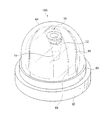
図1は、本発明の一実施形態にかかる監視カメラ100を示す模式図である。図1に示す監視カメラ100は、内部にレンズ装置10を備えた小型の監視カメラであり、ブロードバンド等を用いてインターネット回線に接続可能なIPカメラである。監視カメラ100は、ドーム状の外観を有しており、基台62、透明のケース部材64、およびケース部材64の内部に設けられ、レンズ装置10を覆うカバー部材66を備えている。
FIG. 1 is a schematic diagram showing a
レンズ装置10は、フォーカスリング12、ズームリング14を備えている。フォーカスリング12を回動操作すると、レンズ装置10が備えるフォーカスレンズ(群)16が駆動される。また、ズームリング14を回動操作すると、レンズ装置10が備えるズームレンズ(群)18が駆動される。
The
図2は、レンズ装置10の構成を示す図であって、光軸Pに沿った断面を示している。図1に示すように、レンズ装置10は固定筒20を備えている。固定筒20の内部には、前側(被写体側)にレンズ枠22が配置されており、後側にレンズ枠24が配置されている。また、固定筒20の外側には、フォーカスリング12、ズームリング14が配置されている。
FIG. 2 is a diagram illustrating a configuration of the
レンズ枠22は、フォーカスレンズ(群)16を保持する枠である。レンズ枠22には、その周面よりも突出する係合ピン28が装着されている。一方、固定筒20には、光軸方向に直進溝30が形成されており、係合ピン28が直進溝30に係合することによって、レンズ枠22およびフォーカスレンズ16が、直進溝30にガイドされて光軸方向に直進移動するように構成されている。
The
レンズ枠24は、ズームレンズ(群)18を保持する枠である。レンズ枠24には、その周面よりも突出する係合ピン34が装着されている。一方、固定筒20には、光軸方向に直進溝36が形成されており、係合ピン34が直進溝36に係合することによって、レンズ枠24およびズームレンズ18が、直進溝36にガイドされて光軸方向に直進移動するように構成されている。
The
フォーカスリング12は、レンズ枠22が配置される部位において、固定筒20の外周面に回動可能に配置されている。フォーカスリング12の内周面には、光軸に対して螺旋状にカム溝38が形成されている。レンズ枠22に装着された係合ピン28は、フォーカスリング12のカム溝38に係合する。従って、フォーカスリング12を回動操作すると、フォーカスリング12のカム溝38と固定筒20の直進溝30との交差位置が光軸方向に変位するとともに、その交差位置に従って係合ピン28、レンズ枠22、およびフォーカスレンズ16が光軸方向に変位する。このように、フォーカスリング12を回動操作することによって、フォーカスレンズ16の設定位置を調整してピント調整を行うことができる。
The
ズームリング14は、レンズ枠24が配置される部位において、固定筒20の外周面に回動可能に配置されている。ズームリング14の内周面には、光軸に対して螺旋状にカム溝40が形成されている。レンズ枠24に装着された係合ピン34は、ズームリング14のカム溝40に係合する。従って、ズームリング14を回動操作すると、ズームリング14のカム溝40と固定筒20の直進溝36との交差位置が光軸方向に変位するとともに、その交差位置に従って係合ピン34、レンズ枠24、およびズームレンズ18が光軸方向に変位する。このように、ズームリング14を回動操作することによって、ズームレンズ18の設定位置を調整して焦点距離(ズーム画角)を調整することができる。
The
フォーカスリング12の外周には、ギヤ12aが設けられている。フォーカスリング12のギヤ12aには、後述するフォーカス駆動用のモータ110から駆動力が伝達される。また、ズームリング14の外周には、ギヤ14aが設けられている。ズームリング14のギヤ14aには、ズーム駆動用のモータ112から駆動力が伝達される。
A
固定筒20の後端部には、撮像素子ホルダ44が装着されている。撮像素子ホルダ44には、基板46が装着されている。基板46にはCCD(撮像素子)48が実装されている。CCD48の前側にはシールゴム49が設けられており、シールゴム49の更に前側にはローパスフィルタ(OLPF)50が配置されている。ローパスフィルタ50の前部は、撮像素子ホルダ44の保持部52に当接している。また、ローパスフィルタ50の更に前側には、IRカットフィルタ54が配置されている。IRカットフィルタ54は、赤外線をカットするフィルタと赤外線を透過するフィルタの2つを備えている。IRカットフィルタ54が備える2つのフィルタの切り換えは、モータ(不図示)の駆動によって行われる。
An
本実施形態において、レンズ装置10の撮像光学系は、フォーカスレンズ(群)16及びズームレンズ(群)18によって構成され、被写体から入射した光束は、フォーカスレンズ(群)16及びズームレンズ(群)18によって、CCD48上に結像される。なお、本実施形態では前群レンズにフォーカス機能、後群レンズにズーム機能を持たせたが、前群レンズにズーム機能、後群レンズにフォーカス機能を持たせても良い。
In the present embodiment, the imaging optical system of the
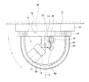
図3は、監視カメラ100が天井に取り付けられた状態を示す断面図である。レンズ装置10は、基台62に対して回動可能に設けられた回転台63に設置されている。基台62には、モータ68が内蔵されており、モータ68の回転軸に装着されたギヤ70と、回転台63の内側に形成されたギヤ72とが係合している。従って、モータ68を駆動すると、モータ68の駆動力がギヤ70、及びギヤ72を介して回転台63に伝達され、回転台63が中心線Cを回転軸として回動する。これにより、レンズ装置10が回動し、レンズ装置10のパンの位置を調整することができる。
FIG. 3 is a cross-sectional view showing a state where the
回転台63には、支持部74が設けられている。支持部74には、回転軸76が挿入されている。そして、レンズ装置10は、支持部74に対して回転軸76を中心として回動可能に支持されている。支持部74の近傍には、モータ78が設置されている。また、レンズ装置10には、回転軸76を中心とする円弧状のギヤ80が固定されている。そして、モータ78の回転軸に装着されたギヤ82と、レンズ装置10のギヤ80とが係合している。従って、モータ78を駆動すると、モータ78の駆動力がギヤ80、及びギヤ82を介してレンズ装置10に伝達され、レンズ装置10が回転軸76を中心として回動する。これにより、図3に示すθが変動し、レンズ装置10のチルト位置を調整することができる。
A
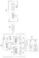
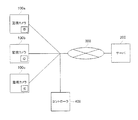
図4は、本実施形態に係る監視カメラシステムを示す模式図である。図4に示すように、本実施形態のシステムは、上述した監視カメラ100と、サーバ200とを備えており、監視カメラ100とサーバ200はインターネットなどの通信回線網300によって接続されている。また、監視カメラ100の機能を制御するため、監視カメラ100にはコントローラ400が接続される。
FIG. 4 is a schematic diagram illustrating the surveillance camera system according to the present embodiment. As shown in FIG. 4, the system of the present embodiment includes the
また、図4は、監視カメラ100、サーバ200、及びコントローラ400の機能構成ブロックを示している。図4に示すように、監視カメラ100は、通信制御部102、ズーム・フォーカス駆動制御部104、パン・チルト駆動制御部106、記憶部108を備えている。通信制御部102、ズーム・フォーカス駆動制御部104、パン・チルト駆動制御部106などの各機能ブロックは、ハードウェアとしての演算処理部(CPUなど)と、演算処理部の内部又は外部のメモリに格納されたコンピュータプログラム(ソフトウェア)とを含むシステムによって構成することができる。また、監視カメラ100で行われる処理をCPUに実行させるプログラムは、磁気ディスクなどの記録媒体に格納されることができる。
4 shows functional configuration blocks of the
通信制御部102は、サーバ200へ情報を送信する送信部、サーバ200から情報を受信する受信部を含み、送信部、受信部の機能を制御する。ズーム・フォーカス駆動制御部104は、フォーカスリング12を駆動するモータ110と、ズームリング14を駆動するモータ112に接続されている。モータ110の回転軸には、フォーカスリング12のギヤ12aと係合するギヤが装着されている。また、モータ112の回転軸には、ズームリング14のギヤ14aと係合するギヤが装着されている。また、パン・チルト駆動制御部106は、パン駆動用のモータ68と、チルト駆動用のモータ78に接続されている。
The
サーバ200は、演算処理部202と、データを格納するデータベース204を有している。サーバ200は、監視カメラ100へ情報を送信する送信部、監視カメラ100から情報を受信する受信部、データベース204から情報を抽出する抽出部等の機能ブロックを含み、これらの機能ブロックは、ハードウェアとしての演算処理部(CPUなど)202と、演算処理部の内部又は外部のメモリに格納されたコンピュータプログラム(ソフトウェア)とを含むシステムによって構成することができる。
The
監視カメラ100が店舗等の天井、壁面等に設置されると、ケース部材64を取り外した状態で、フォーカス、ズーム、パン、チルトの調整が行われる。調整を行う際には、監視カメラ100がコントローラ400に接続される。コントローラ400は、表示部402、操作入力部404を備えている。コントローラ400としては、例えばノート型のパーソナルコンピュータを用いることができるが、これに限られず、調整のための信号を監視カメラ100に送信できるものであれば良い。
When the
本実施形態のシステムでは、監視カメラ100のフォーカス、ズーム、パン・チルトに関する情報が通信回線網300を介してサーバ200から送信され、監視カメラ100の動作が制御される。以下、コンビニエンスストアなどの店舗に監視カメラ100を設置する場合について説明する。店舗に監視カメラ100を設置する場合、店舗内を領域毎に監視するため、複数の監視カメラ100が設置される。
In the system according to the present embodiment, information related to the focus, zoom, pan / tilt of the
店舗内で各監視カメラ100が監視する領域に合わせて、各監視カメラ100のフォーカス、ズーム、パン・チルトの位置が調整される。この際、1台の監視カメラ100でフォーカス、ズーム、パン・チルトの4種類の位置調整が必要となるため、各監視カメラ毎にこれらの調整を行うこととすると、煩雑な作業が必要となる。
The focus, zoom, pan / tilt positions of each
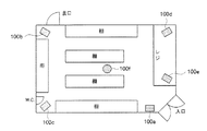
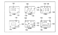
図5は、コンビニエンスストア内の監視カメラ100の配置を示している。図5の例では、6個の監視カメラ100a〜100fが設置されている。このうち、監視カメラ100aは、入口の近傍に配置されている。また、監視カメラ100b,100c,100dは、店内の隅に配置されている。また、監視カメラ100eは、レジの近傍に配置され、監視カメラ100fは店内のほぼ中心部に配置されている。
FIG. 5 shows an arrangement of the
ここで、店舗の規模が同程度であり、陳列棚の配置が同様のコンビニエンスストアの場合、店舗内における各監視カメラ100の配置は、ほぼ同じとすることができる。例えば、同一のフランチャイズチェーンのコンビニエンスストアでは、陳列棚の配置、レジの配置が、複数の予め定められたパターンに従って行われる場合がある。このような場合、各パターンの配置毎に、監視カメラ100の位置、および各監視カメラ100が撮影する領域は、ほぼ同一となる。従って、規模が同程度であり、店内の配置が相互に類似している店舗では、監視カメラ100の設置場所、および各監視カメラ100のフォーカス、ズーム、パン、チルトの調整値を同一に設定することができる。
Here, in the case of a convenience store having the same scale of stores and the same arrangement of display shelves, the arrangement of the
このため、本実施形態では、通信回線網300を介して、店舗の規模、店舗内の陳列棚の配置、及び店舗内の監視カメラ100の配置が類似している店舗を検索し、検索した店舗内の形態パターンに応じて、各監視カメラ100のフォーカス、ズーム、パン・チルトの調整値を取得する。そして、店舗内に新たに設置した監視カメラ100の調整を自動的に行うようにしている。これにより、監視カメラ100の設置の際に、調整のための作業を最小限に抑えることが可能となる。
For this reason, in this embodiment, the store which searched the store where the scale of the store, the arrangement of the display shelf in the store, and the arrangement of the
図6は、検索の結果、サーバ200から送られた店舗の情報をコントローラ400の表示部402に表示した状態を示している。ここでは、店舗の規模、陳列棚の配置等が異なる6つの店舗A〜Fが表示されている。また、各店舗A〜Fに対応して、監視カメラ100の配置位置が表示されている。
FIG. 6 shows a state in which the store information sent from the
店舗に設置した監視カメラ100を調整する場合、コントローラ400の表示部402に表示された各店舗A〜Fの中から、店舗の規模、陳列棚の配置、及び監視カメラ100の設置位置が類似する店舗を選択する。店舗が選択されると、店舗に配置されている各監視カメラ100の調整値(フォーカス、ズーム、パン・チルト)が、通信回線網300を介して監視カメラ100へダウンロードされる。ダウンロードした情報は、監視カメラ100の記憶部108に記憶される。
When adjusting the
そして、調整値に基づいて、フォーカス・ズーム駆動制御部104により、モータ110,112が駆動される。また、調整値に基づいて、パン・チルト駆動制御部106により、モータ68,78が駆動される。これにより、フォーカス、ズーム、パン・チルトの位置が、データベース204に登録された最適な位置に調整される。従って、各監視カメラ100を個別に調整することなく、サーバ200に登録された類似の形態の店舗の調整値を用いて、各監視カメラ100のフォーカス、ズーム、パン・チルトの位置を最適な位置に調整することができる。
The
図7は、店舗内に設置した3つの監視カメラ100a,100b,100cと、サーバ200とが接続された様子を示している。図7に示すように、3つの監視カメラ100a,100b,100cには、店舗内における配置位置を示すIDが付されている。IDは、各監視カメラ100の記憶部108に記憶されている。
FIG. 7 shows a state in which three
サーバ200のデータベース204には、店舗内における監視カメラ100の位置を示すIDと、その監視カメラ100の調整値とが対応付けられて記憶されている。表示部402に表示された各店舗A〜Fの中から特定の店舗を選択すると、サーバ200からは、各監視カメラ100の調整値と、監視カメラ100の店舗内の位置を示すIDとが対応付けられた状態で送信される。監視カメラ100の通信制御部102では、サーバ200から送信された各調整値に付されたIDと、記憶部108に記憶されているIDとの間で認証が行われる。そして、認証が成立した場合は、調整値が監視カメラ100にダウンロードされる。従って、監視カメラ100は、店舗内の位置に応じた調整値を取得することができる。各監視カメラ100は、通信制御部102によってサーバ200から送られた調整値を受信し、記憶部108にダウンロードする。フォーカス・ズーム駆動制御部104、およびパン・チルト駆動制御部106は、調整値に基づいて、モータ68,78,110,112を制御する。
In the
従って、類似した形態の店舗の情報をサーバ200からダウンロードすることで、各監視カメラ100毎にフォーカス、ズーム、パン・チルトを調整する必要がなくなり、煩雑な作業が不要となる。従って、作業効率が向上し、調整を短時間で完了させるとともに、調整のためのコストを最小限に抑えることが可能となる。
Accordingly, downloading store information in a similar form from the
なお、上述した手法により、複数の監視カメラ100を調整した後、さらに各監視カメラ100毎にフォーカス、ズーム、パン・チルトを微調整しても良い。
In addition, after adjusting the plurality of
また上述の説明ではコンビニエンスストアの店舗を例に挙げたが、大型量販店、デパートなどへ監視カメラシステムを導入する場合も同様の手法で行うことができる。この場合、監視カメラシステムが大規模になり、監視カメラ100の台数も多くなるため、本実施形態の手法を適用することでシステム構築にかかる作業効率、コストを大幅に削減することが可能となる。
In the above description, a convenience store is taken as an example, but the same method can be used when a surveillance camera system is introduced to a large mass retailer, a department store, or the like. In this case, since the surveillance camera system becomes large-scale and the number of
また、サーバ100からは、上述した調整値以外にも、監視カメラ100の設定に関する他の情報を受信することが可能である。図8は、サーバ200のデータベース204に格納された、監視カメラ100の動作パターンに関する情報を示している。この動作パターンは、時系列に監視カメラ100に所定の動作をさせる場合に適用されるものである。
In addition to the adjustment values described above, other information related to the settings of the
図8の動作パターンAでは、先ず最初の1分間に、ズームが広角に設定され、パンが0°、チルトがθ=90°に設定される(ステップ1)。ここで、パンの角度は所定の基準方向に対する角度である。また、チルトの角度θは、図3に示すように、水平方向に対する角度である。 In the operation pattern A in FIG. 8, first, zoom is set to a wide angle, pan is set to 0 °, and tilt is set to θ = 90 ° in the first minute (step 1). Here, the pan angle is an angle with respect to a predetermined reference direction. Further, the tilt angle θ is an angle with respect to the horizontal direction as shown in FIG.
次の2分間では、ズームが標準の位置に駆動され、パンが0°から360°へ変化し、回転台が1回転する。また、チルトはθ=45°に設定される(ステップ2)。次の1分間では、ズームが望遠に設定され、パンが0°から45°へ変化し、チルトが70°に設定される(ステップ3)。以降、ステップ1〜ステップ3の動作が繰り返される。
In the next 2 minutes, the zoom is driven to the standard position, the pan changes from 0 ° to 360 °, and the turntable rotates once. The tilt is set to θ = 45 ° (step 2). In the next minute, zoom is set to telephoto, pan changes from 0 ° to 45 °, and tilt is set to 70 ° (step 3). Thereafter, the operations of
また、動作パターンBでは、先ず最初の2分間に、ズームが標準に設定され、パンが0°と180°の間で変化し、チルトがθ=45°に設定される(ステップ1)。次の2分間では、ズームが望遠の位置に駆動され、パンが0°に設定され、チルトがθ=65°に設定される(ステップ2)。次の1分間では、ズームが望遠に設定され、パンが0°から180°の間で変化し、チルトが70°に設定される(ステップ3)。次の2分間では、ズームが広角に設定され、パンが0°に設定され、チルトが90°に設定される(ステップ4)。 In the operation pattern B, first, zoom is set to the standard for the first two minutes, the pan changes between 0 ° and 180 °, and the tilt is set to θ = 45 ° (step 1). In the next two minutes, the zoom is driven to the telephoto position, pan is set to 0 °, and tilt is set to θ = 65 ° (step 2). In the next 1 minute, zoom is set to telephoto, pan changes between 0 ° and 180 °, and tilt is set to 70 ° (step 3). In the next 2 minutes, zoom is set to wide angle, pan is set to 0 °, and tilt is set to 90 ° (step 4).
そして、図6の場合と同様に、図8に示す複数のパターンがコントローラ400の表示部402に表示される。そして、1つの動作パターンを選択すると、選択された動作パターンのデータが監視カメラ100にダウンロードされる。
As in the case of FIG. 6, a plurality of patterns shown in FIG. 8 are displayed on the
ダウンロードされた情報は、監視カメラ100の記憶部108に格納される。ズーム・フォーカス駆動制御部104、パン・チルト駆動制御部106は、記憶部108に格納されたデータに基づいて、各モータ110,112,68,78の駆動を制御する。従って、各監視カメラ100に動作パターンを記憶させるための煩雑な作業が不要となり、作業効率を大幅に向上することが可能となる。
The downloaded information is stored in the
以上説明したように本実施形態によれば、サーバ200から送られた情報に基づいて監視カメラ100を調整することが可能となる。従って、店舗内に複数の監視カメラ100を設置する場合などにおいて、複数の監視カメラ100のそれぞれを調整する必要がなくなり、作業効率を大幅に向上することが可能となる。
As described above, according to the present embodiment, the
以上、添付図面を参照しながら本発明の好適な実施形態について説明したが、本発明は係る例に限定されないことは言うまでもない。当業者であれば、特許請求の範囲に記載された範疇内において、各種の変更例または修正例に想到し得ることは明らかであり、それらについても当然に本発明の技術的範囲に属するものと了解される。 As mentioned above, although preferred embodiment of this invention was described referring an accompanying drawing, it cannot be overemphasized that this invention is not limited to the example which concerns. It will be apparent to those skilled in the art that various changes and modifications can be made within the scope of the claims, and these are naturally within the technical scope of the present invention. Understood.
68,78,110,112 モータ
100 監視カメラ
102 通信制御部
104 ズーム・フォーカス駆動制御部
106 パン・チルト駆動制御部
200 サーバ
204 データベース
300 通信回線網
68, 78, 110, 112
Claims (5)
前記監視カメラは、
所定の機能を動作させる駆動部と、
前記駆動部を動作させるための調整値の要求を、前記監視カメラが設置される場所の形態パターン又は前記監視カメラの動作パターンに応じて前記サーバへ送信する送信部と、
前記サーバから前記調整値を受信する受信部と、
受信した前記調整値に基づいて前記駆動部を制御する駆動制御部と、を備え、
前記サーバは、
前記形態パターン又は前記動作パターンと対応付けて前記調整値を記憶したデータベースと、
前記監視カメラからの要求に応じて、特定の前記形態パターン又は特定の前記動作パターンにおける前記調整値を前記データベースから抽出する抽出部と、
抽出した前記調整値を前記監視カメラへ送信する送信部と、
を備えることを特徴とする、監視カメラシステム。 A surveillance camera system in which a surveillance camera and a server are connected via a communication network,
The surveillance camera is
A drive unit for operating a predetermined function;
A transmission unit that transmits a request for an adjustment value for operating the drive unit to the server according to a form pattern of a place where the monitoring camera is installed or an operation pattern of the monitoring camera;
A receiving unit for receiving the adjustment value from the server;
A drive control unit that controls the drive unit based on the received adjustment value,
The server
A database storing the adjustment value in association with the form pattern or the operation pattern;
In response to a request from the monitoring camera, an extraction unit that extracts the adjustment value in the specific form pattern or the specific operation pattern from the database;
A transmission unit for transmitting the extracted adjustment value to the monitoring camera;
A surveillance camera system comprising:
前記サーバの前記送信部は、前記データベースから抽出した前記調整値と当該調整値に対応する前記位置情報とを前記監視カメラに送信し、
前記監視カメラは、
設置位置を表す位置情報を記憶する記憶部と、
前記サーバから受信した位置情報と、前記記憶部に記憶された位置情報との認証を行う認証部と、を備え、
前記駆動制御部は、前記認証部における認証が成立した場合に、前記調整値に基づいて前記駆動部を制御することを特徴とする、請求項1又は2に記載の監視カメラシステム。 The database of the server stores the position information of the monitoring camera in the form pattern and the adjustment value in association with each other,
The transmission unit of the server transmits the adjustment value extracted from the database and the position information corresponding to the adjustment value to the monitoring camera,
The surveillance camera is
A storage unit for storing position information indicating an installation position;
An authentication unit that authenticates the positional information received from the server and the positional information stored in the storage unit;
The monitoring camera system according to claim 1, wherein the drive control unit controls the drive unit based on the adjustment value when authentication in the authentication unit is established.
前記監視カメラの駆動部を動作させるための調整値を、前記監視カメラが設置される場所の形態パターン又は前記監視カメラの動作パターンに応じて、前記サーバへ要求するステップと、
前記調整値の要求を受信した前記サーバが、前記監視カメラからの要求に応じて、特定の前記形態パターン又は特定の前記動作パターンにおける前記調整値をデータベースから抽出するステップと、
抽出した前記調整値を前記監視カメラへ送信するステップと、
前記監視カメラが受信した前記調整値に基づいて前記駆動部を制御するステップと、
を備えることを特徴とする、監視カメラの調整方法。 A surveillance camera adjustment method used in a surveillance camera system in which a surveillance camera and a server are connected via a communication network,
Requesting the server for an adjustment value for operating the drive unit of the monitoring camera according to a form pattern of a place where the monitoring camera is installed or an operation pattern of the monitoring camera;
The server that has received the request for the adjustment value extracts the adjustment value in the specific form pattern or the specific operation pattern from the database in response to the request from the monitoring camera;
Transmitting the extracted adjustment value to the monitoring camera;
Controlling the drive unit based on the adjustment value received by the monitoring camera;
A method for adjusting a surveillance camera, comprising:
Priority Applications (1)
| Application Number | Priority Date | Filing Date | Title |
|---|---|---|---|
| JP2007002611A JP2008172425A (en) | 2007-01-10 | 2007-01-10 | Surveillance camera system and adjustment method of surveillance camera |
Applications Claiming Priority (1)
| Application Number | Priority Date | Filing Date | Title |
|---|---|---|---|
| JP2007002611A JP2008172425A (en) | 2007-01-10 | 2007-01-10 | Surveillance camera system and adjustment method of surveillance camera |
Publications (1)
| Publication Number | Publication Date |
|---|---|
| JP2008172425A true JP2008172425A (en) | 2008-07-24 |
Family
ID=39700115
Family Applications (1)
| Application Number | Title | Priority Date | Filing Date |
|---|---|---|---|
| JP2007002611A Withdrawn JP2008172425A (en) | 2007-01-10 | 2007-01-10 | Surveillance camera system and adjustment method of surveillance camera |
Country Status (1)
| Country | Link |
|---|---|
| JP (1) | JP2008172425A (en) |
Cited By (4)
| Publication number | Priority date | Publication date | Assignee | Title |
|---|---|---|---|---|
| WO2013114862A1 (en) | 2012-01-30 | 2013-08-08 | パナソニック株式会社 | Optimum camera setting device and optimum camera setting method |
| JP2014507827A (en) * | 2010-12-23 | 2014-03-27 | アルカテル−ルーセント | An integrated method for camera planning and positioning |
| JP2019015653A (en) * | 2017-07-10 | 2019-01-31 | 株式会社日立エルジーデータストレージ | Distance measuring device and method for adjusting angle thereof |
| JP7066492B2 (en) | 2018-04-11 | 2022-05-13 | キヤノン株式会社 | Imaging device |
-
2007
- 2007-01-10 JP JP2007002611A patent/JP2008172425A/en not_active Withdrawn
Cited By (6)
| Publication number | Priority date | Publication date | Assignee | Title |
|---|---|---|---|---|
| JP2014507827A (en) * | 2010-12-23 | 2014-03-27 | アルカテル−ルーセント | An integrated method for camera planning and positioning |
| JP2015181290A (en) * | 2010-12-23 | 2015-10-15 | アルカテル−ルーセント | Integrated method for camera planning and positioning |
| WO2013114862A1 (en) | 2012-01-30 | 2013-08-08 | パナソニック株式会社 | Optimum camera setting device and optimum camera setting method |
| US9781336B2 (en) | 2012-01-30 | 2017-10-03 | Panasonic Intellectual Property Management Co., Ltd. | Optimum camera setting device and optimum camera setting method |
| JP2019015653A (en) * | 2017-07-10 | 2019-01-31 | 株式会社日立エルジーデータストレージ | Distance measuring device and method for adjusting angle thereof |
| JP7066492B2 (en) | 2018-04-11 | 2022-05-13 | キヤノン株式会社 | Imaging device |
Similar Documents
| Publication | Publication Date | Title |
|---|---|---|
| US7956891B2 (en) | Camera control apparatus and method, and camera control system | |
| KR20160144414A (en) | Mount that facilitates positioning and orienting a mobile computing device | |
| CN104410797A (en) | Device and method for celestial body time-lapse photography | |
| JP2001069496A (en) | Supervisory camera apparatus and control method for supervisory camera | |
| WO2009082543A1 (en) | Methods and apparatus for operating a video camera assembly | |
| JP2008172423A (en) | Surveillance camera system, and surveillance camera and control method thereof | |
| JP2008172425A (en) | Surveillance camera system and adjustment method of surveillance camera | |
| JP2001133854A (en) | Camera system and display device | |
| JP5471224B2 (en) | Imaging system, imaging apparatus, information processing apparatus, and imaging method | |
| JP6676347B2 (en) | Control device, control method, and program | |
| CN103167234B (en) | The method for installing CCTV camera | |
| KR20180041866A (en) | Camera linked with POS apparatus and surveillance method using the same | |
| EP3367353B1 (en) | Control method of a ptz camera, associated computer program product and control device | |
| JP2005148265A (en) | Camera apparatus | |
| KR20140116744A (en) | Security camera assembly | |
| US20040201713A1 (en) | Remote control camera system and image transmission method | |
| JP2015012550A (en) | Imaging apparatus and imaging system | |
| JP2002344774A (en) | Imaging unit | |
| JP2004364030A (en) | Monitoring system | |
| KR100452092B1 (en) | Unidentified People Tracking Device Using Dual Cameras And Method Thereof | |
| KR101158819B1 (en) | Method for controlling privacy mask display of monitoring camera | |
| JP2020092308A (en) | Imaging apparatus, control method, and program | |
| JP2013012848A (en) | Camera device and control method therefor | |
| KR101000393B1 (en) | Cctv system and control program therefor | |
| KR101044601B1 (en) | Apparatus and method for setting control information of monitoring camera |
Legal Events
| Date | Code | Title | Description |
|---|---|---|---|
| A300 | Application deemed to be withdrawn because no request for examination was validly filed |
Free format text: JAPANESE INTERMEDIATE CODE: A300 Effective date: 20100406 |